

Page 1

NuWIN-RMv1.0b052
User’s Manual
USM Ver 1.4
Page 2

2
E-mail: sales@xtramus.com
Foreword
Copyright
Copyright © 2015 Xtramus, all rights reserved. The information contained in this document is the property of Xtramus. No part of
this publication shall be reproduced, stored in a retrieval system, or transmitted, in any form or by any means, without the prior
written permission of Xtramus.
Disclaimer
The information contained in this document is subject to change without notice and does not represent a commitment on the part of
Xtramus. The information in this document is believed to be accurate and reliable. However, Xtramus assumes no responsibility or
liability for any errors or inaccuracies that may appear in the document.
Trademarks
NuWIN-RM is a trademark or registered trademark of Xtramus. All other trademarks and registered trademarks are the property of
their respective owners.
Warranty
Xtramus warrants for the hardware provided along with this document under proper usage and conditions in normal environment;
any improper operation or in irregular environment may possibly cause this product NOT function well. For detailed terms, please
contact your local dealer.
Contact Information
E-mail: sales@xtramus.com
Website: www.xtramus.com
Tel: +886-2-8227-6611
Fax: +886-2-8227-6622
XTRAMUS®
Website: www.Xtramus.com
Page 3

3
E-mail: sales@xtramus.com
Date
Version
Software Ver.
History
2011/07/06
1.0
First draft version
2011/08/31
1.1
0.9b038
1. Changing Revision History format: adding
Software Ver.
2. Updating system requirements.
3. Change all pictures and descriptions
accordingly.
4. Adding media type setting sections for all
supporting module cards.
2011/10/05
1.2
v0.9b041
1. Page 6, change FPGA/Firmware version.
2. Change pictures according to the latest
NuWIN-RM.
3. Page 21, change Quick Launch Buttons
descriptions.
4. Page 22, adding Ping Function descriptions.
5. Add 4.7. Layer 3 Reply Setup.
6. Add 4.10. Layer 3 Ping.
7. Delete 4.6.3. Browse Setup – ARP Reply.
8. Delete 4.6.4. Browse Setup – Ping
9. Page 26~37, change table format.
2011/11/18
1.3
v1.0b007
1. Page 6, change supporting module cards’
FPGA/firmware version.
2015/01/13
1.4
v1.0b052
1. Update the descriptions to
NuWIN-RMv1.0b052.
2. Optimize the outlines of the manual.
Revision History
XTRAMUS®
Website: www.Xtramus.com
Page 4

4
E-mail: sales@xtramus.com
Table of Contents
Foreword ........................................................................................................................................ 2
Revision History ............................................................................................................................ 3
1. NuWIN-RM Overview ................................................................................................................. 6
2. Installing/Uninstalling NuWIN-RM ............................................................................................ 7
3. NuWIN-RM Function Overview ............................................................................................... 12
3.1. Starting NuWIN-RM ......................................................................................................... 12
3.2. NuWIN-RM/NuServer Overview ...................................................................................... 16
4. Menu Bar .................................................................................................................................. 18
4.1. File ................................................................................................................................... 18
4.2. View ................................................................................................................................. 20
4.3. Control ............................................................................................................................. 22
4.4. Statistics ......................................................................................................................... 23
4.5.Tool ................................................................................................................................ ... 25
4.6. Language ........................................................................................................................ 26
4.7. Help ................................................................................................................................. 27
5. Quick Launch Buttons ............................................................................................................ 28
6. Module Info/Configuration List ............................................................................................... 31
6.1. Module Information ...................................................................................................... 33
6.2. Reserved Ports ............................................................................................................. 34
6.2.1 Reserved Ports ......................................................................................................... 34
6.2.2 (X, Y, Z):XM-RMxxx ................................................................................................... 36
6.2.2.1 Media Type ...........................................................................................................37
6.2.2.2 Capture Criteria ....................................................................................................38
6.2.2.3 Port Configuration ...............................................................................................40
6.2.2.4 ARP&NDP Configuration .....................................................................................43
6.3. Main Counter ................................................................................................................. 45
6.3.1. Control Buttons ......................................................................................................... 46
6.3.2. Main Display Screen .................................................................................................. 48
6.3.3. Group Control Buttons .............................................................................................. 49
6.4. Browse Setup ................................................................................................................ 50
6.4.1. Overview .................................................................................................................... 51
6.4.2. Traffic Flow ................................................................................................................. 52
6.4.3. Media Type ................................................................................................................. 65
6.4.4. Port Property .............................................................................................................. 67
6.5. Stream Counter ............................................................................................................. 69
6.5.1. SC Summary .............................................................................................................. 70
6.5.2. Tx SC/Tx Stream Counter .......................................................................................... 71
6.5.3. Rx SC/Rx Stream Counter ......................................................................................... 72
6.6. Capture Buffer ................................................................................................................ 73
6.6.1. Control Panel ............................................................................................................. 74
6.6.2. Port ID Tab .................................................................................................................. 75
6.7. Group Setup .................................................................................................................... 77
6.8. Ping Function .................................................................................................................. 78
6.8.1. ARP&NDP Configuration ........................................................................................... 79
6.8.2. Ping Function ............................................................................................................. 80
6.9. DUT Clock Measurement ................................................................................................ 82
6.9.1 Report .......................................................................................................................... 83
6.9.2 (X, Y, Z) ........................................................................................................................ 84
6.10. Pre-configuration .......................................................................................................... 86
6.10.1. Get DUT MAC ........................................................................................................... 87
6.10.2. Router NAT ............................................................................................................... 88
7. Reserve/Release Module ................................................................................................... 90
8. Stream Generation ............................................................................................................ 91
8.9.1. Control Buttons ......................................................................................................... 92
XTRAMUS®
Website: www.Xtramus.com
Page 5

5
E-mail: sales@xtramus.com
8.9.2. Tx Rate Control ................................ ................................................................ .......... 93
8.9.3. Stream Transmit Mode .............................................................................................. 94
8.9.4. Main Display ............................................................................................................... 95
8.9.4.1. Adding New Streams ..........................................................................................95
8.9.4.2. Stream Settings ...................................................................................................97
9. Editing Protocol with Frame Data Edit Window ................................................................ .... 99
9.1. Link Layer Type ............................................................................................................ 100
9.1.1. Ethernet II ................................................................................................................. 100
9.1.2. IPX ............................................................................................................................ 100
9.1.3. User Defined ............................................................................................................ 101
9.2. Tags ............................................................................................................................... 102
9.2.1. VLAN ......................................................................................................................... 102
9.2.2. Q-in-Q ....................................................................................................................... 102
9.2.3 MPLS ......................................................................................................................... 103
9.3. Layer 3 Header .............................................................................................................. 104
9.3.1. IPv4 ........................................................................................................................... 104
9.3.3. ARP ........................................................................................................................... 106
9.3.4. Pause ........................................................................................................................ 106
9.4. Layer 4 Header .............................................................................................................. 107
9.4.1. TCP/IP ....................................................................................................................... 107
9.4.2. UDP/IP ...................................................................................................................... 107
9.4.3. ICMP/IP ..................................................................................................................... 108
9.4.4. IGMP/IP ..................................................................................................................... 108
9.5. Frame View .................................................................................................................... 110
XTRAMUS®
Website: www.Xtramus.com
Page 6
6
E-mail: sales@xtramus.com
Module Cards Support NuWIN-RM
Module Card
FPGA Version
Firmware Version
XM-RM661/671/681
V3.0b016
v1.5b059
XM-RM751/761/781
V3.0b016
v1.5b059
XM-RM731
v2.0b004
v1.4b062
XM-RM881
v1.3b005
v0.1b106
XM-RM891
v1.3b003
v1.4b011
*Note: NuStreams-2000i and NuStreams-600i are required as well.
OS
Windows 2000/Windows XP
Windows Vista/Windows 7
RAM
512MB RAM
1GB RAM
CPU
Pentium 1.3GHz or Higher
HDD
10 GB Available Space
*Note: Large amount of data will be generated while running NuWIN-RM. It is
recommended to preserve enough available Hard-Disk space to store these data.
1. NuWIN-RM Overview
NuWIN-RM provides a powerful and sophisticated virtual front panel to manage the
NuStreams-2000i and NuStreams-600i chassis. Each test port can be independently
configured with parameters to define streams, filters, and capture capabilities. Traffic for
various network protocols can be customized, transmitted, and received on each port.
Comprehensive statistics provide users an in-depth analysis of the performance of the DUT (Device under
Test).
NuWIN-RM has a flexible and intuitive interface to control test modules in a single or multiple chassis
through a click of the mouse. Any combination of test modules can be inserted into NuStreams chassis and
be instantly identified.
Each port can be configured to analyze and count packets to match user-defined criteria, such as source
and destination MAC addresses, custom patterns, errors, and frame size ranges. Each port is equipped
with capture memory, which can store packets in real time. A comprehensive set of user-defined triggers
and filters are available based on source and/or destination MAC and/or IP addresses, data patterns, and
error conditions.
NuWIN-RM is designed to allow multiple users to access individual ports of every test module installed.
This feature enables users to execute their own tests on the ports assigned to them without disrupting
other users on the system.
NuWIN-RM is designed for Xtramus XM-RM series module cards. The table down below contains the
XM-RM module cards, FPGA/Firmware/PROM versions that are supported by NuWIN-RM.
Also, please make sure that your PC meets the requirements listed in the table down below before
installing NuWIN-RM.
XTRAMUS®
Website: www.Xtramus.com
Page 7
7
E-mail: sales@xtramus.com
Installing NuWIN-RM
1. Double-click NuWIN-RM installation program
and start the installation process.
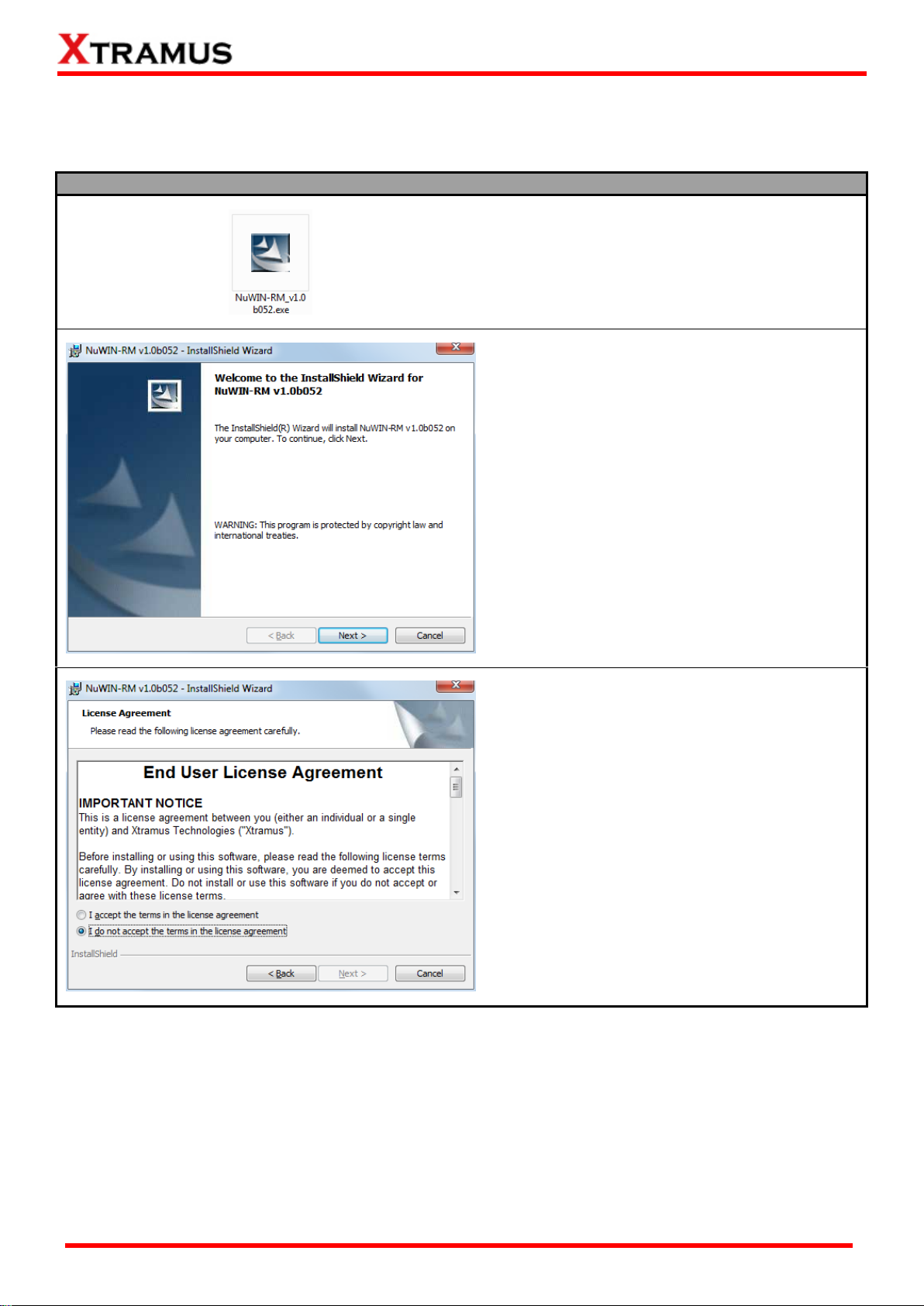
2. InstallShield Wizard is starting to install
NuWIN-RM. If you would like to cancel
installation, click “Cancel”, or Click “Next” to
continue installation.
3. Choose “I accept the terms in the license
agreement” and click Next to continue the
installation. Click Back to return to the
previous step. Or if you do not agree with the
end user license agreement, please click
“Cancel” to exit the InstallShield Wizard.
2. Installing/Uninstalling NuWIN-RM
Please follow the steps down below to install NuWIN-RM.
XTRAMUS®
Website: www.Xtramus.com
Page 8
8
E-mail: sales@xtramus.com
Installing NuWIN-RM
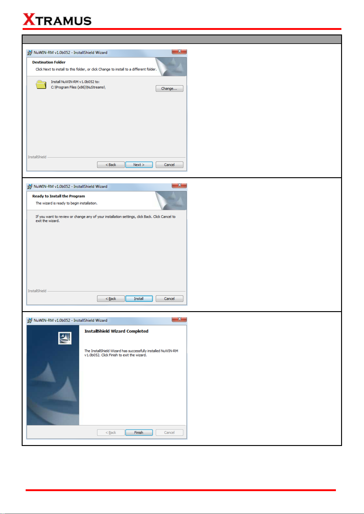
4. Set the file path where you want to install
NuWIN-RM.
5. Click Install to continue the installation. If
you want to review or change any of your
installations settings, click Back. Or Click
Cancel to exit the wizard.
6. Click Finish, then the installation of NuWIN is
completed.
*Note: Due to different Operating Systems or system settings, warning messages might pop up when
installing NuWIN-RM. When this occurs, please choose the options on these pop-up warning messages
that allow you to continue installing NuWIN-RM.
XTRAMUS®
Website: www.Xtramus.com
Page 9
9
E-mail: sales@xtramus.com
Installing NuWIN-RM
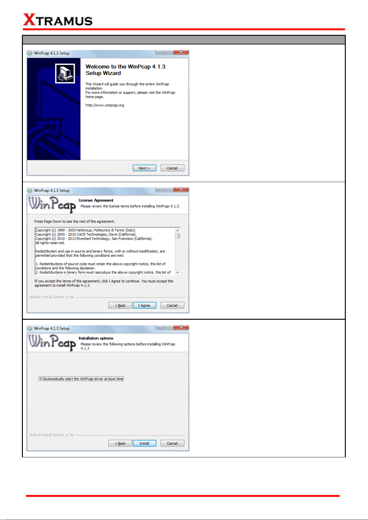
7. If your PC does not have WinPcap installed,
a WinPcap Installer window will pop up.
Click Next button to get ready to install, or
click Cancel button to stop. For more detail
information regarding to WinPcap, please
visit their webpage at: www.winpcap.org.
8. Review the license agreement before
installing. Click I Agree button to continue. It
is necessary to accept the agreement to
install WinPcap.
9. You can set if you would like to start WinPcap
driver when booting PC by clicking the
check-box. Click “Install” to continue.
XTRAMUS®
Website: www.Xtramus.com
Page 10
10
E-mail: sales@xtramus.com
Installing NuWIN-RM
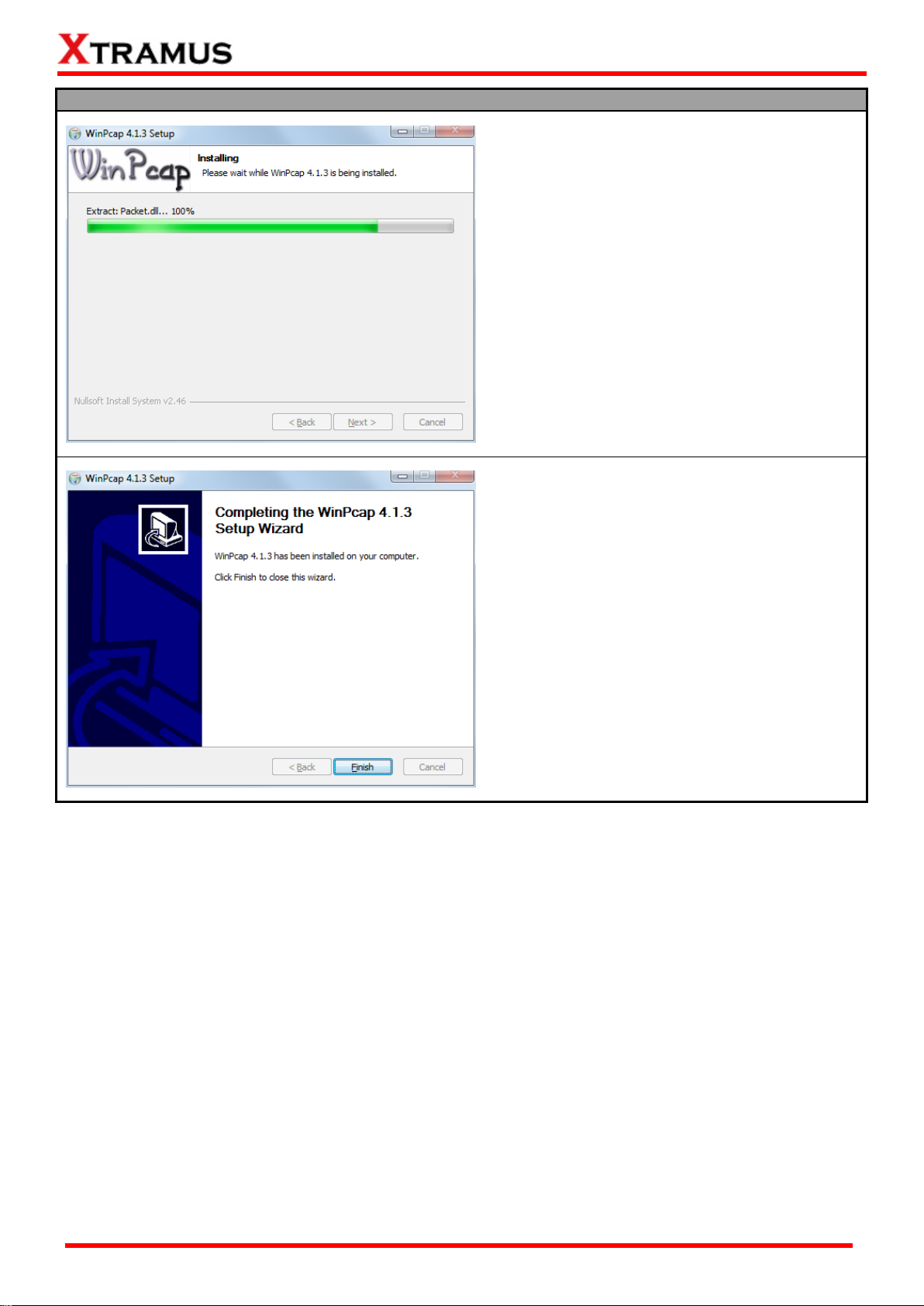
10. WinPcap is installing.
11. WinPcap installation completes. Click Finish
button to close the wizard.
XTRAMUS®
Website: www.Xtramus.com
Page 11
11
E-mail: sales@xtramus.com
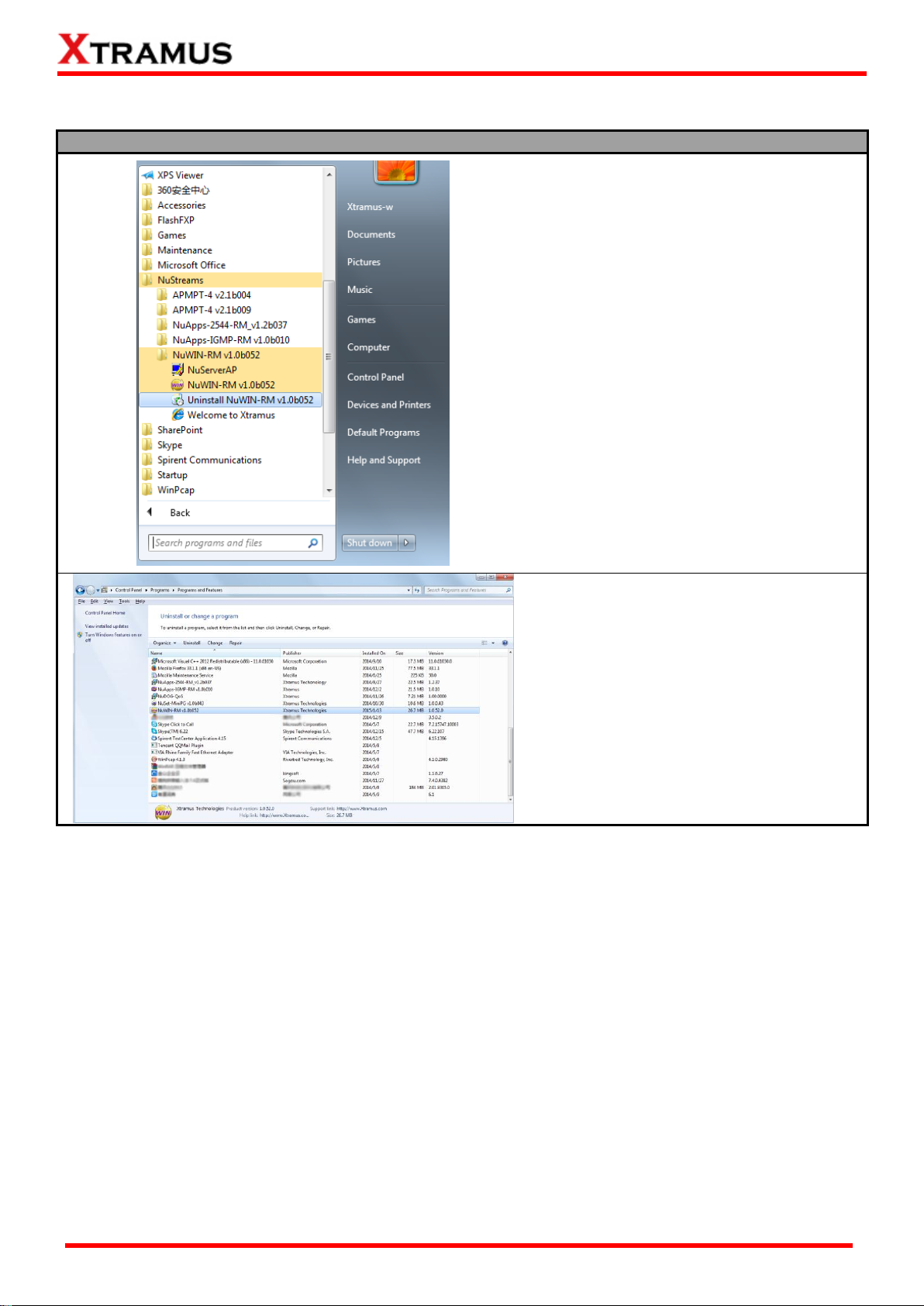
Uninstalling NuWIN-RM
Click Start All Programs
NuStreams NuWIN-RM v1.0b052
Uninstall NuWIN-RM v1.0b052.
Go to the Control Panel and uninstall the
program.
You can uninstall NuWIN-RM by:
XTRAMUS®
Website: www.Xtramus.com
Page 12
12
E-mail: sales@xtramus.com
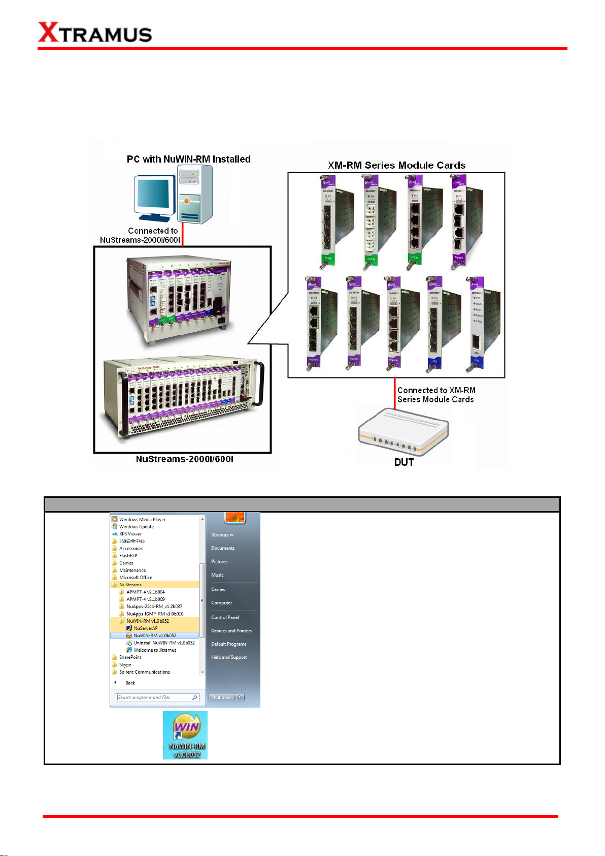
Starting NuWIN-RM
Click Start All Programs NuStreams
NuWIN-RM v1.0b052 NuWIN-RM
v1.0b052.
Double-click NuWIN-RM icon located on
your PC’s desktop.
3. NuWIN-RM Function Overview
3.1. Starting NuWIN-RM
Before starting NuWIN-RM, the DUT, your PC, and NuStreams-2000i/600i shall be connected properly as
shown in the picture down below:
There are two ways to start NuWIN-RM:
XTRAMUS®
Website: www.Xtramus.com
Page 13
13
E-mail: sales@xtramus.com
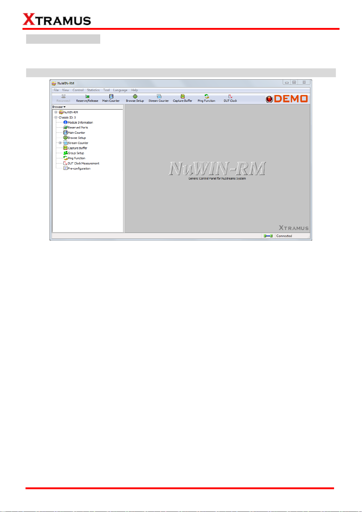
NuWIN-RM Demo Mode
If your PC is not connected with NuStreams-2000i/600i, you can still run NuWIN-RM under Demo Mode.
Almost all NuWIN-RM’s functions are available under Demo Mode.
Note:Demo Mode is for system demo purposes only, and does not serve any testing purposes at all.
XTRAMUS®
Website: www.Xtramus.com
Page 14
14
E-mail: sales@xtramus.com
Starting NuServer
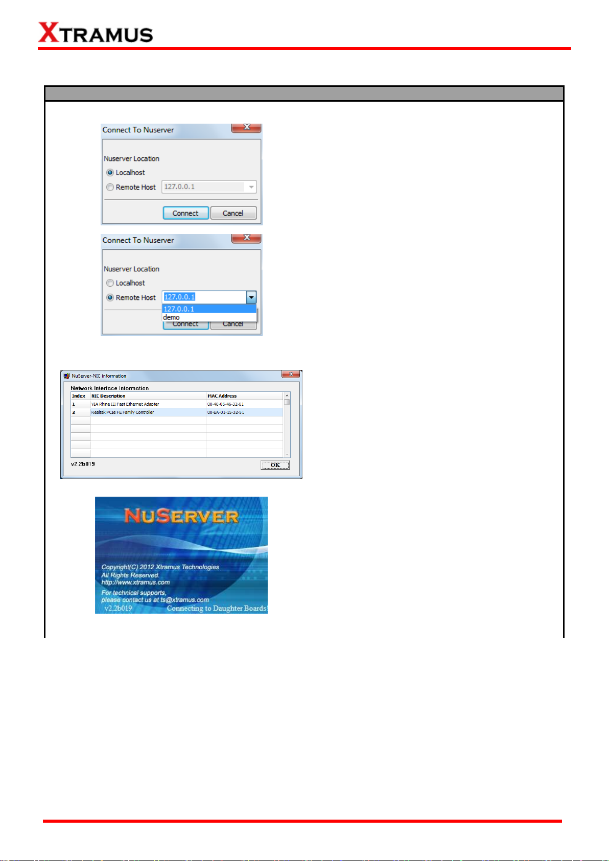
When starting NuWIN-RM, a “Connect To
NuServer” window will pop up and ask how you
are going to connect to NuServer.
Local Host: Choose this option when you’re
running NuWIN-RM from NuStreams-2000i
IPC module or a PC that’s connected to
NuStreams-2000i/600i via an RJ45 cable.
Remote Host: Choose this option when
you’re running NuWIN-RM from other PC
located on the network. Choose the IP
address which is assigned from
NuStreams-2000i/600i from the scroll-down
menu, or choose demo to enter NuWIN-RM’s
Demo Mode.
Connect/Cancel: Click the Connect/Cancel
button to connect to NuStreams-2000i/600i or
cancel starting NuWIN-RM.
A “NuServer-NIC Information” window will pop
up. Please select the NIC (Network Interface
Card) which is connected to NuStreams -2000i/
600i’s from the Network Interface Information
table, and click OK. If you’re using
NuStreams-2000i’s IPC module, please choose
“Realtek RTL8139 Family Fast Ethernet”.
NuServer will connect to the daughter boards,
and NuWIN-RM will start as well.
Please follow the steps down below to start NuWIN-RM and NuServer properly.
XTRAMUS®
Website: www.Xtramus.com
Page 15
15
E-mail: sales@xtramus.com
Starting NuServer
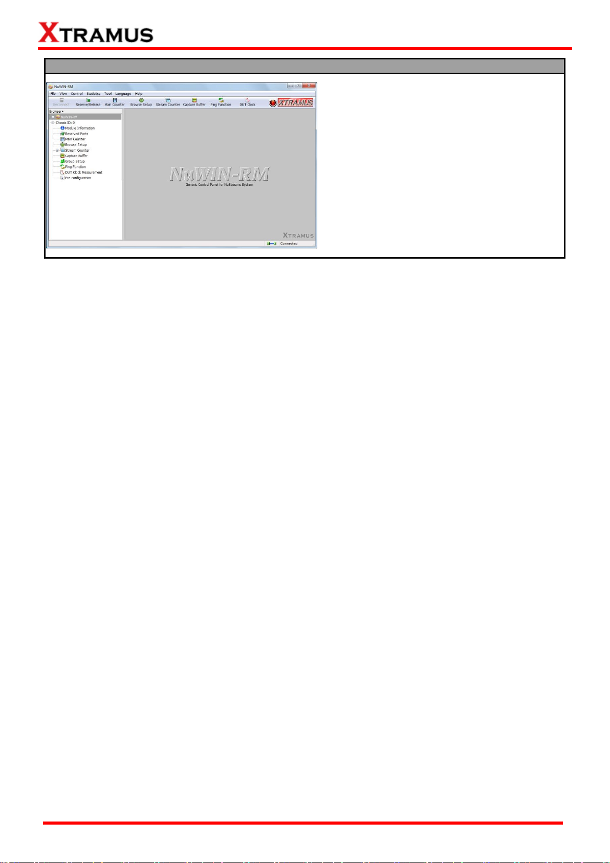
You now have accessed to NuWIN-RM’s main
display window.
XTRAMUS®
Website: www.Xtramus.com
Page 16
16
E-mail: sales@xtramus.com
NuWIN-RM Functions Overview
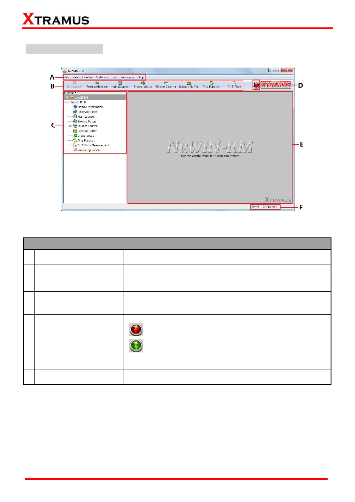
A
Menu Bar
The Menu Bar allows you to make settings about test criteria,
load/save settings you’ve made, and change language displayed.
B
Quick Launch Buttons
The Quick Launch Buttons allow you to reconnect your PC to
NuStream-2000i/600i, open/save test settings, make test
configurations, and view test reports.
C
Module Info/Configuration
List
By clicking the Module Info/Configuration List, you can view system
information, making test configurations, or view test reports on the
Main Display Screen.
D
Status Icon
The Status Icon shows the running status of NuWIN-RM.
No test is underway.
Test is running.
E
Main Display Screen
You can make detail configurations and view real-time testing diagrams
on the Main Display Screen.
F
System Connection Status
This icon shows the connection status between your PC and
NuStreams-2000i/600i.
3.2. NuWIN-RM/NuServer Overview
NuWIN-RM Main Window
XTRAMUS®
Website: www.Xtramus.com
Page 17
17
E-mail: sales@xtramus.com
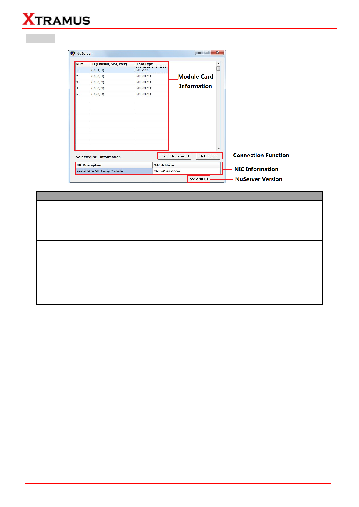
Description
Module Card
Information
This section displays the information regarding to the module cards that are
installed on NuStreams-2000i/600i. Module Card IDs are showed as the
format of (X, Y, Z) while X is the chassis ID (which is displayed on
NuStreams-2000i/600i), Y is the slot number where this module card is
installed, and Z is the available port number located on the module card.
Connection
Function
You can reconnect a link down status or force to disconnect your
NuStreams-600i/2000i to your PC.
NIC Information
This section displays the detail information (including NIC Model name,
NIC’s MAC address) regarding to the selected NIC.
NuServer Version
This section displays the version of your NuServer.
NuServer
XTRAMUS®
Website: www.Xtramus.com
Page 18
18
E-mail: sales@xtramus.com
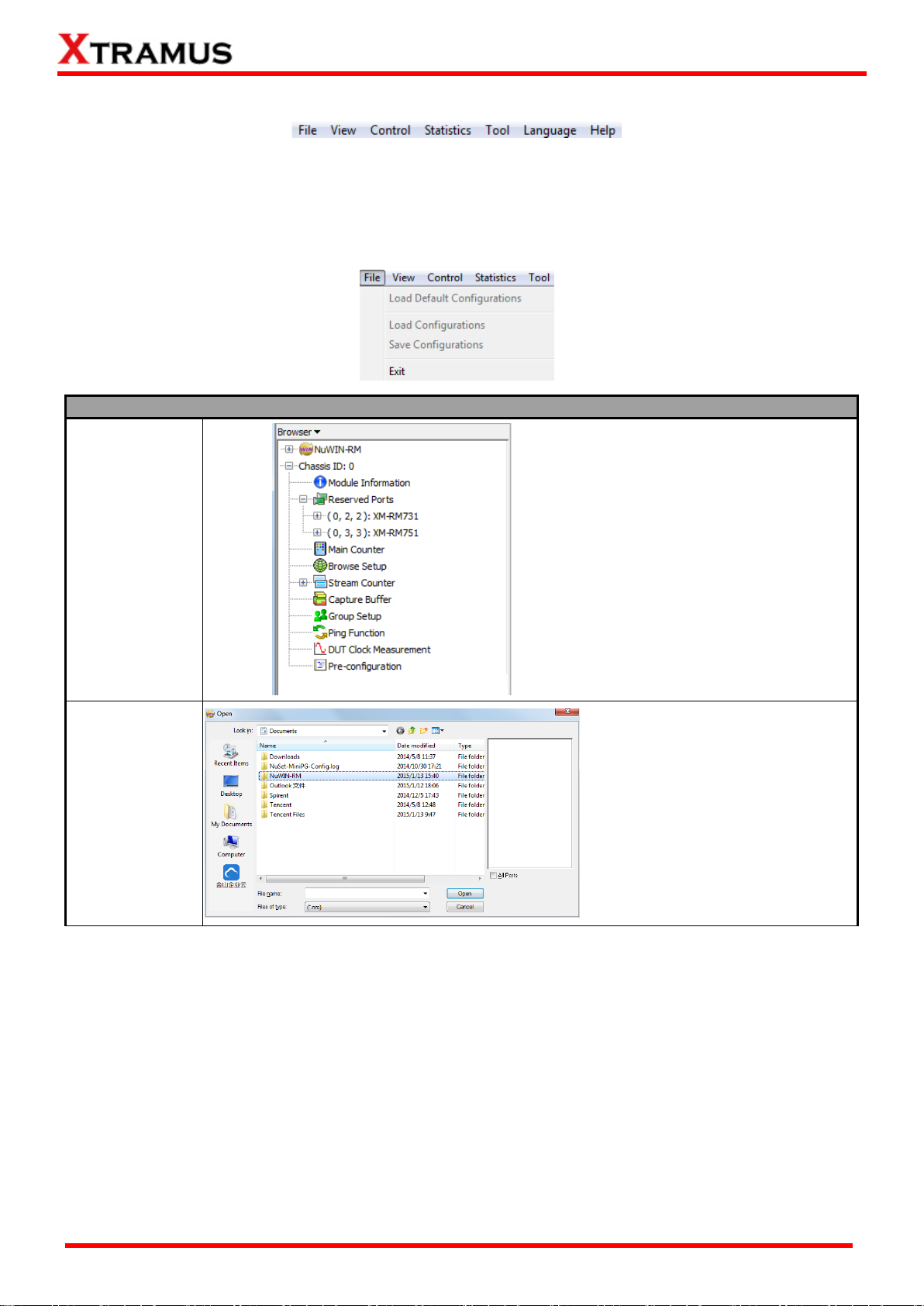
File
Load Default
Configurations
Reset all the settings to default,
including settings in the Module
Info/Configuration List, as shown
in the picture on the left.
Load
Configurations
If you have a previously saved
configuration setting file in your PC,
you can load it and apply all the
setting you’ve made by choosing
“Load Configurations” from the
Menu Bar.
All configuration files are saved in
the format of “*.cfg”.
4. Menu Bar
NuWIN-RM’s Menu Bar includes configuration options such as File, View, Control, Statistics,
Language, and Help. Please refer to the sections down below for detail information regarding to each
configuration option.
4.1. File
XTRAMUS®
Website: www.Xtramus.com
Page 19
19
E-mail: sales@xtramus.com
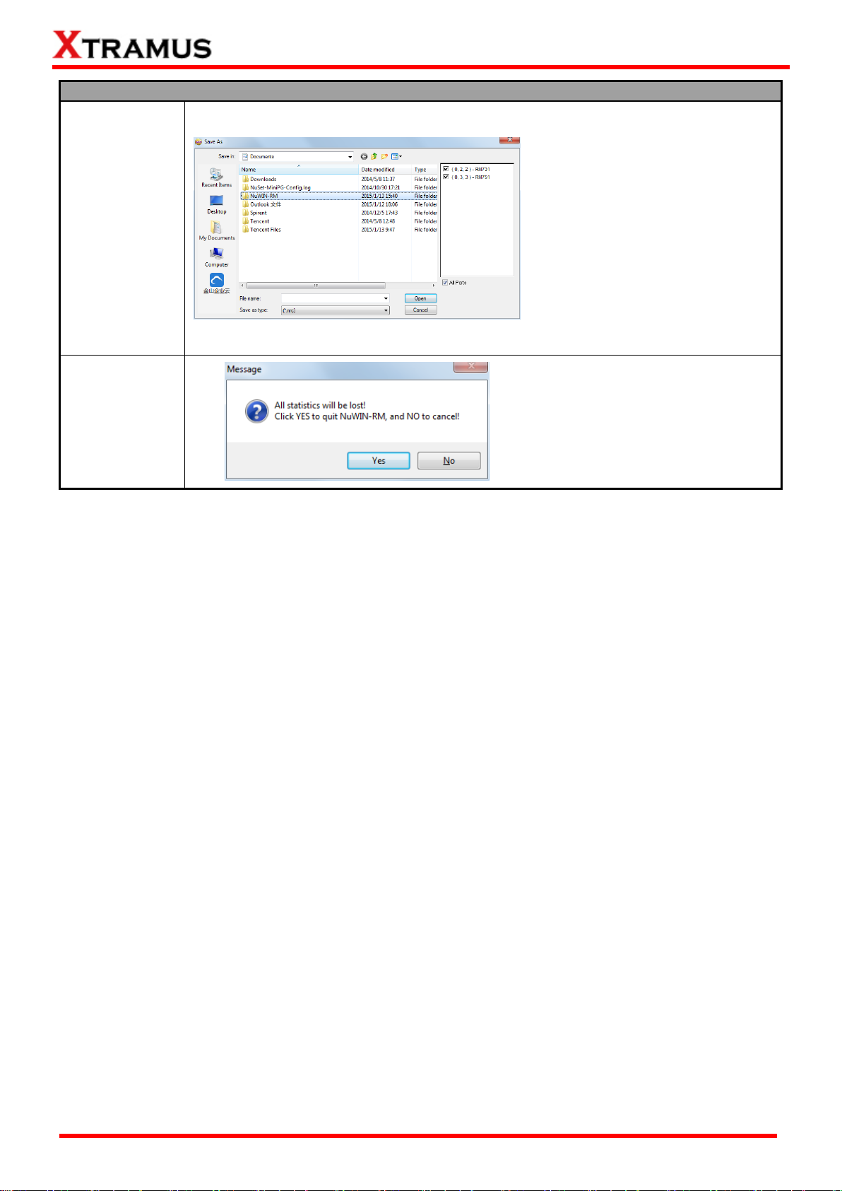
File
Save
Configurations
You can save the current
configuration settings to your PC by
choosing “Save Configurations”
from the Menu Bar.
All configuration files are saved in
the format of “*.cfg”.
Exit
A prompt pop-up window will ask if
you would like to close NuServer as
well. Click Yes to exit NuWIN-RM,
or click No to cancel.
XTRAMUS®
Website: www.Xtramus.com
Page 20
20
E-mail: sales@xtramus.com
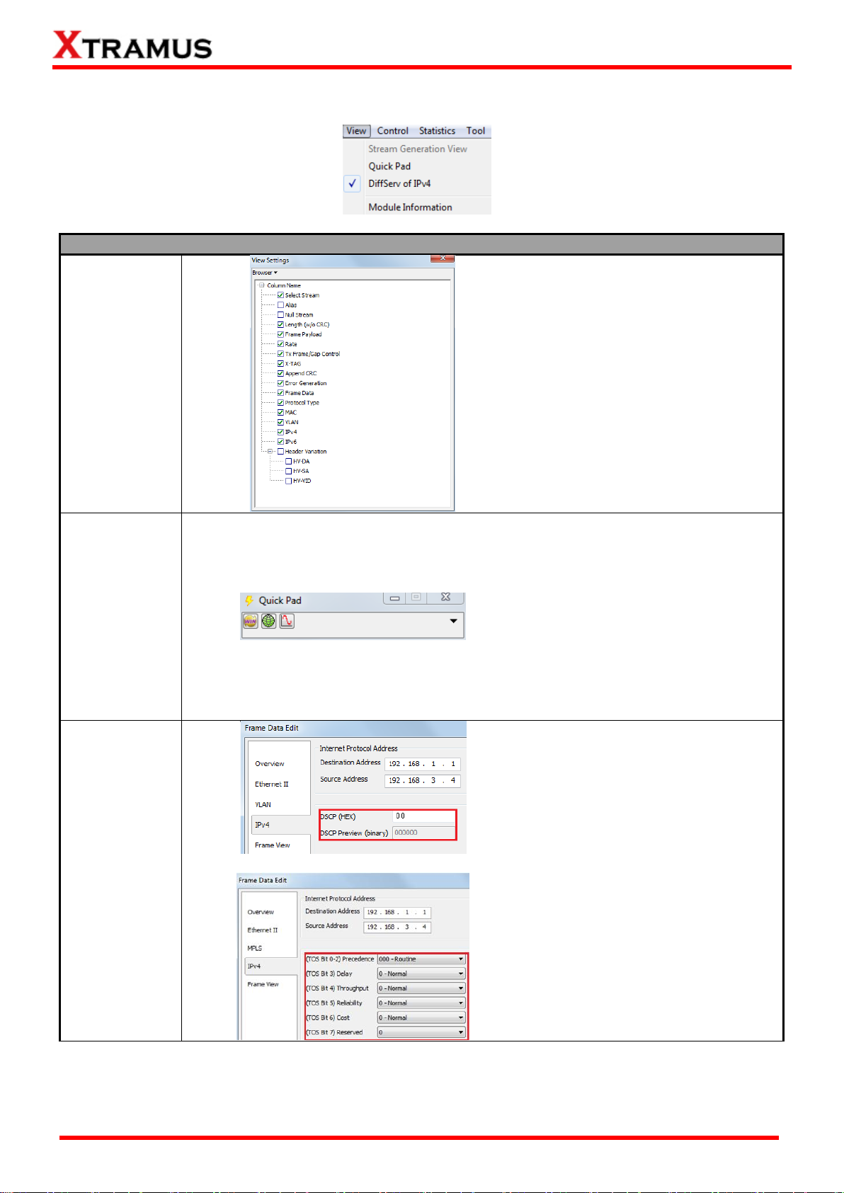
View
Stream
Generation
View
Click Stream Generation View, then
the View Settings window will pop
up. The settings you make here will
be applied to all the reserved ports.
Group Setup
Click Quick Pad, then the small
Quick Pad window will pop up. The
icons of the currently opened or
minimized configuration window will
be displayed here to facilitate the use
of next time.
DiffServ of IPv4
Check Diffserv of IPv4 here, the
QoS priority settings will be DSCP,
shown as the upper picture on the
left.
Uncheck Diffserv of IPv4 here, the
QoS priority settings will be ToS,
shown as the lower picture on the
left.
4.2. View
XTRAMUS®
Website: www.Xtramus.com
Page 21
21
E-mail: sales@xtramus.com
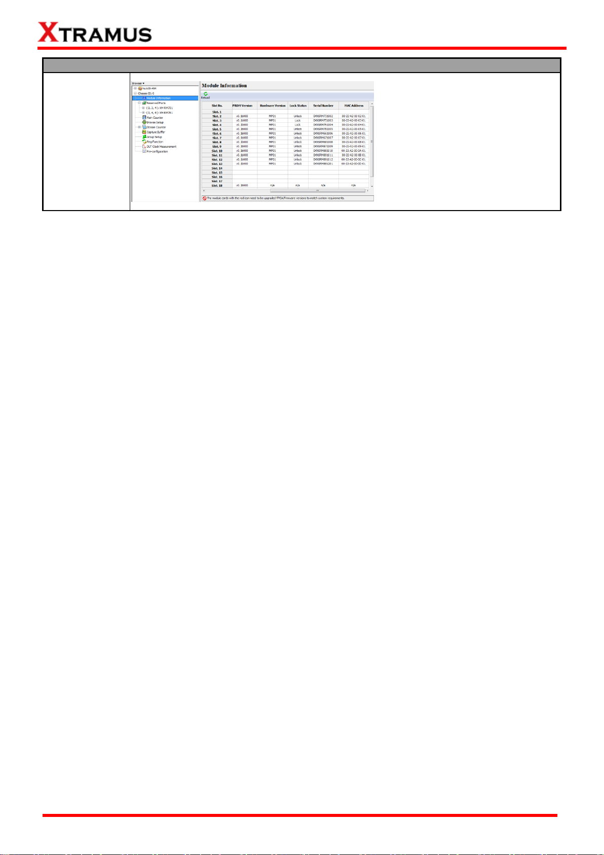
View
Module
Information
Check Module Information here,
the detailed module information will
be displayed in the main display
screen.
XTRAMUS®
Website: www.Xtramus.com
Page 22
22
E-mail: sales@xtramus.com
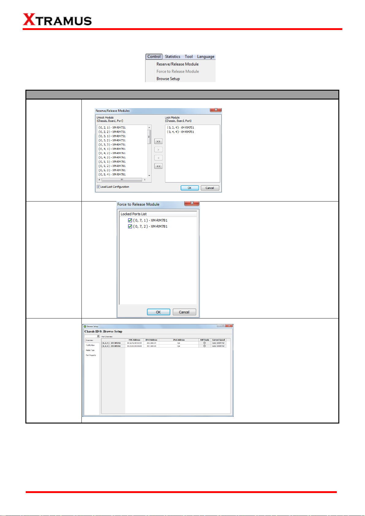
Control
Reserve/Release
Module
A Reserve/Release Modules
window will pop up if you choose
Reserve /Release Module from
the Menu Bar.
You can choose the module cards
you would like to reserve or
release on the Reserve/Release
Modules window.
For detailed information, please
refer to 7. Reserve/Release
Module.
Force to Release
Module
Generally, the Force to Release
Module function is gray. But if the
function turns black, it means
some active ports are locked so
as to not available to use. In this
case, please click this function to
pop up the window on the left to
force release the locked ports.
Browse Setup
A Browse Setup Window will pop
up if you choose Browse Setup
from the Menu Bar.
You can view or change test
settings on the Browse Setup
window.
For detailed information, please
refer to 6.4. Browse Setup.
4.3. Control
XTRAMUS®
Website: www.Xtramus.com
Page 23
23
E-mail: sales@xtramus.com
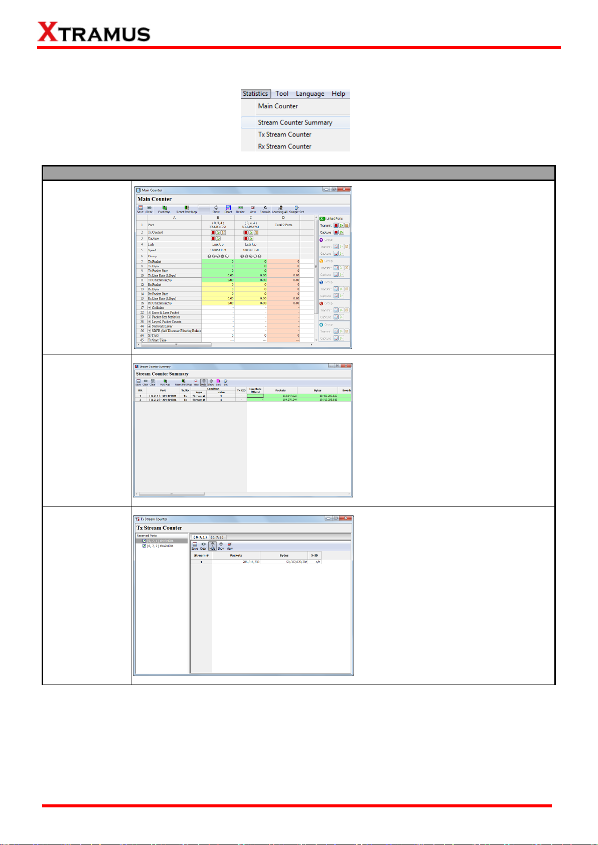
Statistics
Main Counter
Window
A Main Counter window will pop up if
you choose Main Counter from the
Menu Bar.
You can view counter reports, start/stop
packet counts on the Main Counter
window.
For detailed information, please refer to
6.3. Main Counter.
Stream Counter
Summary
Stream Counter Summary allows the
user to view the test data of his interest.
For detailed information, please refer to
6.5.1 SC Summary.
Tx Stream
Counter
Tx Stream Counter allows the user to
view the Tx test data of his interest.
For detailed information, please refer to
6.5.2 Tx SC/ Tx Stream Counter.
4.4. Statistics
XTRAMUS®
Website: www.Xtramus.com
Page 24
24
E-mail: sales@xtramus.com
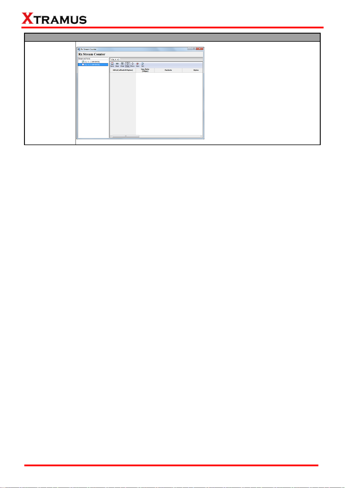
Statistics
Rx Stream
Counter
Rx Stream Counter allows the user to
view the Rx test data of his interest.
For detailed information, please refer to
6.5.3 Rx SC/ Rx Stream Counter.
XTRAMUS®
Website: www.Xtramus.com
Page 25
25
E-mail: sales@xtramus.com
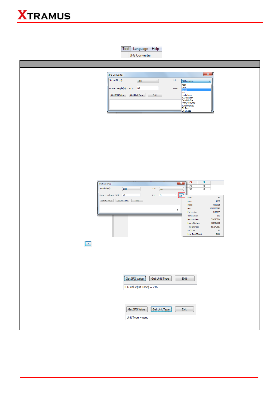
Tool
IFG Converter
IFG Converter allows the user to converter the frame gap among different units.
Speed: set the network speed from the scroll down menu.
Frame Length (w/o CRC): Set the length of the packet by inputting the desired
value.
Unit: Select a unit of frame gap from the scroll down menu.
Rate: Select a value for the Unit. For example, if you select nsec for Unit and 96
for rate, it means 96 nsec.
Click the button on the right, you can view the frame gap in other units
automatically converted by this tool and displayed in the pop-up window.
Get IFG value: Click this button, the frame gap in unit of Bit Time will be displayed
in the down area.
Get Unit Type: Click this button, the unit type will be displayed in the down area.
Exit: Exit this function and close IFG Converter window.
4.5.Tool
XTRAMUS®
Website: www.Xtramus.com
Page 26

26
E-mail: sales@xtramus.com
Language
English
NuWIN-RM supports 4 different languages for its UI.
4.6. Language
Note: As to the current version of NuWIN-RM, only English UI is supported.
XTRAMUS®
Website: www.Xtramus.com
Page 27
27
E-mail: sales@xtramus.com
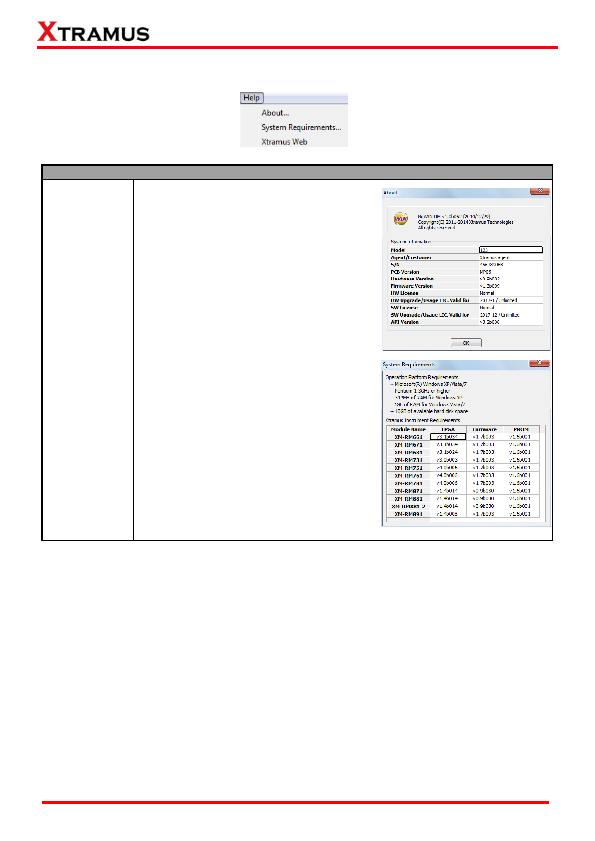
Help
About
An “About” window will pop up and show detailed
system information.
System
Requirements
A “System Requirements” window will pop up
and show the requirements for your PC and the
FPGA/Firmware/PROM of the module cards.
OK: Click this button to exit the “System
Requirements” pop-up window.
Xtramus Web
Access Xtramus Website (www.xtramus.com).
4.7. Help
XTRAMUS®
Website: www.Xtramus.com
Page 28
28
E-mail: sales@xtramus.com
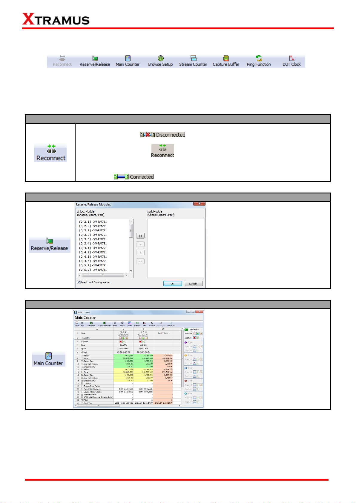
Reconnect
If the connection between your PC and NuStreams-2000i/600i is down, a
“Disconnected” icon will be shown in “System Connection Status”.
Press Reconnect button to re-establish the connection between your PC and
NuStreams-2000i/600i. If the connection has been established successfully, a message
window will pop up, and the “System Connection Status” will be shown as
“Connected” .
Reserve/Release
A Reserve/Release Modules window will
pop up if you choose Reserve /Release
Module from the Menu Bar.
You can choose the module cards you
would like to reserve or release on the
Reserve/Release Modules window.
For detailed information, please refer to 7.
Reserve/Release Module.
Main Counter
A Main Counter window will pop up if you
press the Main Counter button on the
Quick Launch Buttons.
You can view counter reports, start/stop
packet counts on the Main Counter
window.
For detailed information, please refer to
6.3. Main Counter Window.
5. Quick Launch Buttons
These Quick Launch Buttons allow you to reconnect NuStreams-2000i/600i, reserve/release module
cards, view counter statistics, browse/configure system settings, and perform Ping commands. Please
refer to the section down below for more detail descriptions regarding to Quick Launch Buttons.
XTRAMUS®
Website: www.Xtramus.com
Page 29
29
E-mail: sales@xtramus.com
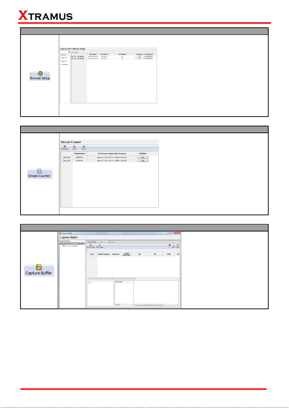
Browse Setup Window
A Browse Setup window will pop up if you
press the Browse Setup button on the Quick
Launch Buttons.
You can view or change test settings on the
Browse Setup window.
For detailed information, please refer to 6.4.
Browse Setup Window.
Stream Counter
A Stream Counter window will pop up if you
press the Ping Function on the Quick
Launch Buttons.
You can view the packet transmission and
receiving statistics and edit the packet
receiving rules here.
For detailed information, please refer to 6.5.
Stream Counter.
Capture Buffer
A Capture Buffer window will pop
up if you press the Capture Buffer
on the Quick Launch Buttons.
You can set capture buffer criteria or
start/stop capturing packets here.
For detailed information, please
refer to 6.6. Capture Buffer.
XTRAMUS®
Website: www.Xtramus.com
Page 30
30
E-mail: sales@xtramus.com
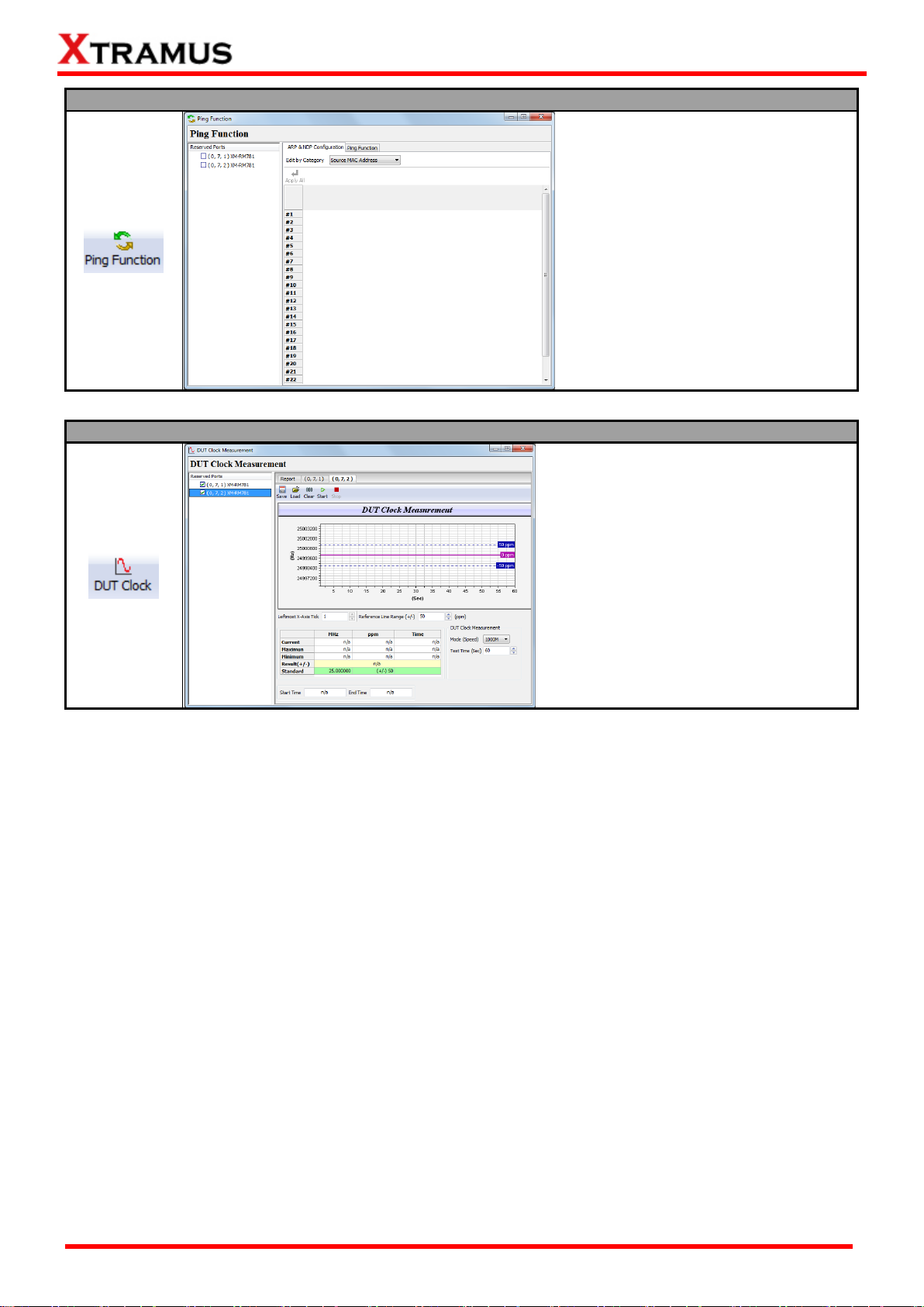
Ping Function Window
A Ping Function window will pop up if
you press the Ping Function on the
Quick Launch Buttons.
You can perform layer 3 Ping on the
Ping Function window.
For detailed information, please refer to
6.8. Ping Function.
DUT Clock Measurement Window
A DUT Clock Measurement window will
pop up if you press the DUT Clock on the
Quick Launch Buttons.
You can test the Crystal Oscillator’s
frequency of the DUT and see if it’s either
faster or slower than standard speed in
ppm scale.
For detailed information, please refer to
6.9. DUT Clock.
XTRAMUS®
Website: www.Xtramus.com
Page 31

31
E-mail: sales@xtramus.com
About
An “About” window will pop up and show detailed system
information.
Please note that to view system information on the About
pop-up window, you have to reserve module cards installed in
your NuStreams-2000i/600i chassis first.
For detailed information regarding to how to reserve module
cards, please refer to 7. Reserve/Release Module.
Connect to NuServer
If the connection between your PC and NuServer is down, a “Disconnected” icon will
be shown in “System Connection Status”.
Press Connect to NuServer to re-establish the connection between your PC and NuServer. If the
connection has been established successfully, a message window will pop up, and the “System
Connection Status” will be shown as “Connected” .
6. Module Info/Configuration List
The Module Info/Configuration List allows you to view system information, making configurations, and
check test reports. You can fold/unfold the tree style tab by clicking / icons on the System Info
/Configuration List.
As shown in the picture above, Module Info/Configuration’s tree style tab menu are divided into two
categories: NuWIN-RM and Chassis ID.
NuWIN-RM
Unfold NuWIN-RM , You can see the figure down below.
XTRAMUS®
Website: www.Xtramus.com
Page 32

32
E-mail: sales@xtramus.com
Chassis ID
Chassis ID means the ID number of the chassis, which will exactly be displayed behind the colon.
The Chassis ID list contains the main functions of NuWIN-RM, including Module Information,
Reserved Ports, Main Counter, Browse Setup, Stream Counter, Capture Buffer, Group
Setup, Ping Function, DUT Clock Measurement and Pre-configuration. For detailed
information about these functions, please see the sections down below.
XTRAMUS®
Website: www.Xtramus.com
Page 33

33
E-mail: sales@xtramus.com
Module Information
If you click Module Information from the Module Info/Configuration List, the Main Display Screen will
display Module Information as shown in the picture above.
The following information can be viewed on Module Information:
Slot No.: This field displays the slot number of the module card.
Module Name: This field displays the module name of the module card.
Firmware Version: This field displays module card’s firmware version.
FPGA Version: This field displays module card’s FPGA version.
PROM Version: This field displays module card’s PROM version
Hardware Version: This field displays module card’s hardware version.
Lock Status: This field display module card’s current status. If a port has been reserved for tests,
the Lock Status field will show Lock. If a port is not selected and reserved for tests, the Lock
Status field will show Unlock.
Serial Number: This field displays the serial number of the device.
MAC Address: This field displays the serial number of the module card.
6.1. Module Information
XTRAMUS®
Website: www.Xtramus.com
Page 34

34
E-mail: sales@xtramus.com
A. Control Buttons
Save: This button allows you to save the current module settings.
Load: This button allows you to load previously saved module settings.
Learning All: Learning packets will be transmitted from all ports and keep a table contains
Source MAC Address of each received packets.
Learning Marked: Learning packets will be transmitted from marked ports and keep a table
contains Source MAC Address of each received packets.
Apply All: Apply changes you’ve made to all ports.
Apply Marked: Apply changes you’ve made to marked ports.
B. Port Info & Operation
6.2. Reserved Ports
All reserved ports that you’ve reserved for tests will be listed here as shown in the picture right.
For detailed information about how to reserve/release ports, please refer to 7. Reserve/Release Module.
6.2.1 Reserved Ports
Click Reserved Ports on the Module Info/Configuration List, the following interface will be displayed on
the Main Display Screen, shown as the picture down below. The interface can be divided into two parts: A.
Control Buttons and B. Port Info & Operation.
XTRAMUS®
Website: www.Xtramus.com
Page 35

35
E-mail: sales@xtramus.com
Mark: You can mark the specific port by clicking the Mark icon.
Module Name: This field displays the module name of the module card.
Link Status: This field displays the link status of the module card.
Tx Control: You can start/stop transmitting test packets through the designated port by the
control buttons in this field.
Stop: To stop transmitting test packets, press button. If the designated port is not
transmitting packets, the button will be instead.
Start: To start transmitting test packets, press button. If the designated port is
transmitting packets, the button will be instead.
Pause: To pause, press button. If the designated port is pausing, the button will be
instead.
Capture: You can start/stop capturing packets that meets the filtering settings by the control
buttons in this field.
Stop: To stop capturing test packets, press button. If the designated port is not capturing
packets, the button will be instead.
Start: To start capturing test packets, press button. If the designated port is capturing
packets, the button will be instead.
Streams: This field displays the number of data stream contained in the port.
Current Speed: This field displays the speed of the designated port.
Apply: Click this button to apply all the settings you’ve made for the port.
XTRAMUS®
Website: www.Xtramus.com
Page 36

36
E-mail: sales@xtramus.com
6.2.2 (X, Y, Z):XM-RMxxx
When clicking (X, Y, Z):XM-RMxxx, the Stream Generation page of the port will be displayed on the Main
Display Screen, as shown in the picture above.
For detailed information about configuring the data stream, please refer to 8.Stream Generation.
Under each port, there are four sub-functions to configure the port, namely Media Type, Capture Criteria,
Port Configuration and ARP&NDP Configuration. Please see the section down below for details.
XTRAMUS®
Website: www.Xtramus.com
Page 37

37
E-mail: sales@xtramus.com
6.2.2.1 Media Type
When clicking Media Type, a (X, Y, Z): Media Configuration window will pop up, where (X, Y, Z) is
module card’s port ID. You can make media settings for the designated port here on pop-up Media Type
Setup window.
The Media Type Setup window varies from different module cards you’ve reserved for the tests. Please
refer to the sections down below for media type settings.
The functions and operations on the Media Configuration window are concluded as follows:
Manual Speed Mode: This function allows you to manually set the transmitting rate. Force here
means the transmitting rate of the port will switched to the selected mode even if the connection fails.
Auto Negotiation Mode: This function allows automatically negotiate the transmitting rate between
the two communication ports. You can select the transmitting rate in the Auto Negotiation Mode
area.
Auto-MDIX: MDIX is a technology that automatically detects the required cable connection type
(straight-through or crossover) and configures the connection appropriately. Click the Auto-MDIX
scroll-down menu to enable or disable this function.
Force MDI-II: force the port to be Force MDI-II type.
Force MDI-X: force the port to be Force MDI-X type.
Copper/Fiber Mode: Only when the Manual Speed Mode is set to be Manual Speed Mode, this
function is available. Please set the media type according to the practical type of the port. If the port is
electrical, please select Copper Mode, and if the port is optical, please select Fiber Mode.
Master/Slave Mode: Only when the Manual Speed Mode is set to be Manual Speed Mode, this
function is available. The two ends of the connection will be set as Master or Slave. If both ends of
the connection are set to the same, the link of that connection will be down. Please set the module
card’s port accordingly here, or choose Auto Detect so NuWIN-RM will detect and set the
transmitting mode automatically.
Link Down: If this function is selected, this port will be closed and unable to use. All connections to
this port will be cut off.
Link Up: Select this function to enable this port. The connections to this port are available to be
established.
OK: Press this button to apply all the changes you’ve made and exit.
Cancel: Press this button to cancel all the changes you’ve made and exit.
XTRAMUS®
Website: www.Xtramus.com
Page 38

38
E-mail: sales@xtramus.com
A. Protocol
Protocol allows you to set the criteria for packet capturing.
Capture All Packets: Click this check box to capture all packets.
Criteria: The capture criteria supported here includes Pause Packet, ARP, ICMP, CRC Error,
IPv4 Checksum Error, Oversize, and Under 64 Bytes.
6.2.2.2 Capture Criteria
When clicking Capture Criteria, a Port (X, Y, Z): Capture Criteria window will pop up, where (X, Y, Z) is
the module card’s port ID. You can set packet capturing criteria for the designated port here on the pop-up
Capture Criteria window.
The Capture Criteria contains 3 menu tabs: A. Protocol, B. SDFR, and C. Result. Please see the
sections down below for details.
XTRAMUS®
Website: www.Xtramus.com
Page 39

39
E-mail: sales@xtramus.com
B. SDFR
SDFR (Self-Discover Filtering Rules) is a technology that makes packet capturing/filtering over
Ethernet easy and convenient. SDFR parameters include filter of Layer 3 Destination IP Address (DIP)
and Source IP Address (SIP)
Each filter is independent and can be activated in any combinations. You can choose the criteria by
clicking the check boxes.
You can set and input the value of DIP and SIP on the upper-right part of the SDFR Menu. The value of
SDFR parameters can be set as Single, Pair, and Range. The following descriptions will use DA as
example.
Single: A single value will be used as SDFR parameter.
Pair: Two values will be used as SDFR parameters.
Range: Values within the range of the two values set here will be used as SDFR parameters.
C. Result
The Result page will display the settings you’ve made in Protocol and SDFR pages.
XTRAMUS®
Website: www.Xtramus.com
Page 40

40
E-mail: sales@xtramus.com
A. Flow Control
Flow Control:This function is used to release the network congestion situations. Including Tx Flow
Control and Rx Flow Control.
Rx Rate Control: Enable this function to control the rate of receiving data. You can input the
maximum receiving speed of the port in Rate Limited.
B. Random Packet Length
Force All Streams to Random Length: when this function is enabled, all streams of the port will be
in a random length between the Minimum value and the Maximum value set in Random Packet
Length (w/o CRC).
Dynamic Random Seed: Enable this function, then the random packet of different streams will be
different, or packet lengths of all streams may be the same.
Random Packet Length (w/o CRC): Set the range of the random packet length.
6.2.2.3 Port Configuration
When clicking Port Configuration, a Port (X, Y, Z): Port Configuration window will pop up, where (X, Y,
Z) is module card’s port ID. You can make port configurations for the designated port here on the Port
Configuration pop-up window.
The Port Configuration window contains 6 menu tabs: A. Flow Control, B. Random Packet Length, C.
X-TAG Offset, D. BERT, E. Data Integrity (DI), and F. Elongated Frame Gap. Please see the sections
down below for more detailed descriptions.
XTRAMUS®
Website: www.Xtramus.com
Page 41

41
E-mail: sales@xtramus.com
C. X-TAG Offset
X-TAG is a 12-byte tag developed by Xtramus, embedded in the transmitted packets, which is an
enhance measure to check the validation of data transmission on the network. When the starting position
of the X-TAG in the received packet by the other port of the two communication ends coincides with the
Byte set in Check Offset, then the data transmission between the two communication ends is supposed
to be validate. The Byte in Check Offset should be set based on the Byte in Tx Offset.
Tx Offset: Set the starting position of the X-TAG in the transmitted packet from the scroll down
menu.
Check Offset: Set the starting position of the X-TAG in the received packet from the scroll down
menu. Auto Check means the system will automatically select the right Byte for this function.
D. BERT
BERT stands for Bit Error Rate Test.
Transmit BERT: Adding BERT patterns to transmitted packets if this is enabled.
Check BERT: NuWIN-RM will check if BERT patterns are in received packets.
XTRAMUS®
Website: www.Xtramus.com
Page 42

42
E-mail: sales@xtramus.com
E. Data Integrity (DI)
Transmit DI: When enabled, NuWIN-RM will check data integrity of transmitted packets.
Check Received DI: When enabled, NuWIN-RM will check data integrity of received packets.
F. Elongated Frame Gap
When this function is enabled and the transmitting packet flow reaches wirespeed, a 1 byte-time of frame
gap will be inserted after a certain amount of packets are transmitted. This can reduce packet loss
caused by crystal frequency differentials between DUT and test instrument. Enabling Elongated Frame
Gap can compensate crystal frequency differentials by around 30 ppm as simulation.
XTRAMUS®
Website: www.Xtramus.com
Page 43

43
E-mail: sales@xtramus.com
ARP&NDP
Configuration
ARP&NDP Configuration – Assign MAC address and IP address pairs to one port
ARP, namely address resolution protocol, is a TCP/IP protocol to obtain the MAC
address based on the IP address. NDP, namely neighbor discovery protocol, is a
replacement of ARP in IPv6.
You can assign multiple MAC address and IP address pairs to one port. As long as the
IP address in the ARP request fits one of the assigned pairs, the port will response the
ARP request.
To assign a specific MAC address and IP address pair to the port, check the
corresponding line in the most left Enable column. For example, in the picture down
below, the MAC address and IP address pairs from line 4 to line 8 are selected.
Meanwhile, you must enable the ARP or NDP according the type of the IP address
(IPv4 or IPv6) by check the corresponding line in the ARP or NDP Enable column.
Note: please check the ARP Enable column for IPv4 and check the NDP Enable
column for IPv6. Or, the MAC address and IP address pair is not successfully assigned
to the port.
ARP&NDP Configuration – Buttons
Enable: right-click the Enable area shown in the above left picture, a menu will
pop up to facilitate the enabling operations, shown as the above right picture.
Enable: check all the lines of the column.
Disable: uncheck all the lines of the column.
6.2.2.4 ARP&NDP Configuration
XTRAMUS®
Website: www.Xtramus.com
Page 44

44
E-mail: sales@xtramus.com
Invert: If the line is checked, then uncheck it or reverse.
OK: Press this button to apply all the changes you’ve made and exit.
Cancel: Press this button to cancel all the changes you’ve made and exit.
XTRAMUS®
Website: www.Xtramus.com
Page 45

45
E-mail: sales@xtramus.com
Accessing Main Counter Window
Choose Main Counter from the Menu Bar
Press the Main Counter button on the Quick Launch Buttons
Click Main Counter Window on the Module Info/Configuration
List
Main Counter Window Descriptions
A
Control Buttons
These buttons allow you to save the counter report, clear all
statistics, hide/show counter information, resize the Main
Counter Window, and export the current counter to
Microsoft Excel.
B
Main Display Screen
You can view counter statistics or start/stop transmitting
/capturing packets here in this section.
C
Group Control Buttons
These buttons allow you to start/stop transmitting/capturing
packets in groups.
6.3. Main Counter
The Main Counter window allows you to start/stop transmitting/capturing packets. You can access the
Main Counter window by:
A Main Counter window will pop up as shown in the picture below.
Please see the following sections for detail descriptions.
XTRAMUS®
Website: www.Xtramus.com
Page 46

46
E-mail: sales@xtramus.com
Control Buttons Descriptions
The Save button allows you to save the current counter reports to Microsoft Excel® format
files.
The Clear button allows you to clear all statistics displayed on the Main Display Screen.
The Port Map button allows you set the ports the statistics of which you want to view. Only
the statistics of the selected ports will be displayed in the Main Display Screen.
The Reset Port Map button allows you to clear all the ports you selected in the Port Map.
The Hide button allows you to hide some of the TX/Rx statistics, as well as fold all tree style
tab statistics on the Main Display Screen.
The Show button allows you to show all TX/Rx statistics, as well as unfold all tree style tab
statistics on the Main Display Screen.
The Chart button allows you to intuitively view the general trend of the TX/Rx line rate of the
reserved port, shown as the picture down below.
You can select the ports in C and choose the rate type in D. The rate type including Tx Line
Rate and Rx Line Rate. And the colors of the corresponding rate are shown in D. Then
click the Start button in A to plot the chart.
Taking the above figure for an example, the Elapsed time-Rate chart of port (0, 7, 1)
XM-RM781 will be plotted in B after click the Start button and in the chart, there will be one
green line and a blue line, respectively representing the Tx Line Rate and Rx Line Rate.
And you can operate the chart through the operation buttons in A. For more information,
see Operation buttons.
Operation buttons
Save the current chart in “.bmp” format.
Start to plot the chart.
Stop to plot the chart.
6.3.1. Control Buttons
Please refer to the section down below for more detail descriptions regarding to the following contents.
XTRAMUS®
Website: www.Xtramus.com
Page 47

47
E-mail: sales@xtramus.com
Control Buttons Descriptions
Clear the chart.
Set x-axis scale and y-axis scale of the chart.
The Resize button allows you to set the width of Main Counter window. The maximum/
minimum value for the Main Counter window width is from 80 to 300.
The View button allows you to set the detailed terms that will be displayed on the Main
Display Screen. Click the View button and then a three style list will pop up. You can select
the terms you want to display from the list.
The Formula function provides some formulas to allow you to do the corresponding
operations on the Main Display Screen. This is a tool for the user to judge the performance
of the DUT. Double Click the write blank cell, and then enter your formula, eg. SUM (A1,
A2). Or right-click the write blank cell, then choose Insert Formula. See the picture down
below for more information.
Click the Formula button, the Formula Help window will pop up. You can refer the function
lists on the left for details.
Learning packets will transmit to all the ports.
The Sample Set function allows you to set data updating interval
of the main counters. Click the Sample Set button, the following
window will pop up.
Auto: the data updating interval will be default value.
Manual: you can set the data updating interval in the
Interval (seconds) textbox.
XTRAMUS®
Website: www.Xtramus.com
Page 48

48
E-mail: sales@xtramus.com
Main Display Screen Descriptions
The Main Display Screen displays counter report statistics of all ports you’ve selected for test. Also,
you can start/stop capturing packets or start/stop transmitting packets by the control buttons in this
field.
Stop: To stop capturing test packets or transmitting packets, press button. If the
designated port is not capturing packets or transmitting packets, the button will be instead.
Start: To start capturing test packets or transmitting packets, press button. If the
designated port is capturing packets or transmitting packets, the button will be instead.
6.3.2. Main Display Screen
XTRAMUS®
Website: www.Xtramus.com
Page 49

49
E-mail: sales@xtramus.com
Group Control Buttons Descriptions
The Group Control Buttons allow you to start/stop capturing packets or start/stop transmitting
packets in groups. You can assign a group ID number to reserved ports for test managements.
Stop: To stop capturing test packets or transmitting packets, press button. If the
designated group is not capturing packets or transmitting packets, the button will be
instead.
Start: To start capturing test packets or transmitting packets, press button. If the
designated group is capturing packets or transmitting packets, the button will be instead.
6.3.3. Group Control Buttons
XTRAMUS®
Website: www.Xtramus.com
Page 50

50
E-mail: sales@xtramus.com
Accessing Browse Setup Window
Choose Browse Setup from the Menu Bar
Press the Browse Setup button on the Quick Launch
Buttons
Click Browser Setup on the Module Info/Configuration List
Browse Setup Window Overview
This icon allows you to hide Browse Setup window menu list on the left side.
Overview
You can view/configure MAC Address and IP Address here. Also, you can view each
port’s ARP Reply status and Current Speed here as well.
Traffic Flow
You can set the network type here. NuWIN-RM supports One to Multi, Pair, Rotate, and
Mesh. Also, you can edit frame here as well.
Media Type
You can set reserved ports’ media type here.
Port Property
The Port Property allows you to access settings that are available in Port Configuration
of Module Info/Configuration List.
6.4. Browse Setup
The Browse Setup window allows you to view/configure test settings. You can access the Browse Setup
window by:
Please note that you have to reserve ports for test (which is mentioned in 7. Reserve/Release Module)
before accessing the Browse Setup window.
Please see the sections down below for more detailed information about Browse Setup window.
Note: When you press the Apply button and apply all settings you’ve made, NuWIN-RM will save all the
current settings and apply these settings when you run NuWIN-RM next time.
XTRAMUS®
Website: www.Xtramus.com
Page 51

51
E-mail: sales@xtramus.com
Browse Setup – Overview
(X, Y, Z) – Module Name
All available ports will be displayed here in the format of (X, Y, Z) – Module
Name, where (X, Y, Z) is module card’s port ID.
MAC Address
This field displays the MAC addresses of the preserved ports. Also, you can
click the MAC address field of a specific port to change its MAC address.
IP Address
This field displays the IP addresses of the preserved ports. Also, you can click
the IP address field of a specific port to change its IP address.
ARP Reply
This field shows if the ARP Reply is enabled or not. If enabled, the icon will turn
green ; if not, the icon will turn gray .
Current Speed
This field displays the preserved ports’ current transmitting speed.
6.4.1. Overview
You can view/configure MAC Address and IP Address here. Also, you can view each port’s ARP Reply
status and Current Speed here as well.
XTRAMUS®
Website: www.Xtramus.com
Page 52

52
E-mail: sales@xtramus.com
6.4.2. Traffic Flow
You can set the network type here. NuWIN-RM supports One to Multi, Pair, Rotate, and Mesh. Also,
you can edit frame here as well.
You can set NuWIN-RM’s network mode by clicking the scroll-down menu located on the upper-left part
of the Browse Setup window, as shown in the picture on the right.
Settings available here will change according to the network type you’ve selected here. Please see the
sections down below for detailed descriptions.
XTRAMUS®
Website: www.Xtramus.com
Page 53

53
E-mail: sales@xtramus.com
A. One to Multi Network
In One to Multi network mode, packets will be sent from one Root Port to multiple Member Ports as
shown in the picture above. Also, these Member Ports can send packets to the source Root Port as
well.
There are two menu tabs available here: Ports Arrangement and Streams Setting:
Ports Arrangement: this tab allows you to assign Root Port and Member Ports. To know more
about assigning Root Port and Member Ports, please see the “One to Multi –Ports
Arrangement” section.
Stream Setting: this tab allows you to edit packet frames. To know more about edit packet
frames, please refer to E. Editing Frame.
XTRAMUS®
Website: www.Xtramus.com
Page 54

54
E-mail: sales@xtramus.com
One to Multi –Ports Arrangement
1. You can configure the streams
transmitted from the Member
Ports to the Root Port in the
Up Stream area.
2. The port you’ve assigned will
be displayed on the Root Port
field. If you would like to
remove that port as root port,
click the < button.
3. To assign an available port as
the Member Port, click the port
and press the > button as
shown in the picture on the left.
If you would like to assign all
available ports as the Member
Port, press the >> button.
4. The port you’ve assigned will
be displayed on the Member
Port field. If you would like to
remove a port from the
Member Port field, click the
port you would like to remove,
and press the < button. If you
would like to remove all ports
from the Member Port field,
press the << button.
5. You can view the MAC Address
and IPv4 Address of Root Port
and Member Ports. You can
manually input the IPv6
Address by double click the
IPv6 Address column.
6. Press the Apply button to apply
all the settings you’ve made.
XTRAMUS®
Website: www.Xtramus.com
Page 55

55
E-mail: sales@xtramus.com
One to Multi –Stream Setting
You can configure the streams
transmitted from the Member
Port to the Root Port in the
Up Stream area.
You can configure the streams
transmitted from the Root Port
to the Member Port in the Up
Stream area.
Press the Apply button to apply
all the settings you’ve made.
XTRAMUS®
Website: www.Xtramus.com
Page 56

56
E-mail: sales@xtramus.com
B. Pair Network
In Pair network mode, two reserved ports will work as a pair, transmitting/receiving packets to/from each
other as shown in the picture above.
There are two menu tabs available here: Port Arrangement and Stream Setting:
Ports Arrangement: this tab allows you to assign ports. To know more about assigning ports,
please see the “Pair –Ports Arrangement” section.
Stream Setting: this tab allows you to edit packet frames. To know more about edit packet
frames, please refer to E. Editing Frame section.
XTRAMUS®
Website: www.Xtramus.com
Page 57

57
E-mail: sales@xtramus.com
Pair – Assigning Ports
1. To add an available port for Pair
Network Mode, click the port and
press the > button as shown in the
picture on the left. If you would like to
add all ports, please press the >>
button.
2. The port you’ve assigned will be
displayed on the Ports field. If you
would like to remove that port, click
the < button. If you would like to
remove all ports, click the << button.
3. You can view the MAC Address and
IPv4 Address of the assigned ports.
You can manually input the IPv6
Address by double click the IPv6
Address column.
4. Press the Apply button to apply all the
settings you’ve made.
Pair –Stream Setting
You can configure the streams of
the assigned ports here.
Press the Apply button to apply all
the settings you’ve made.
XTRAMUS®
Website: www.Xtramus.com
Page 58

58
E-mail: sales@xtramus.com
C. Rotate Network
In Rotate network mode, packets will be sent from port to port in a loop while the last port will be
connected to the first port, as shown in the picture above.
There are two menu tabs available here: Ports Arrangement and Stream Setting:
Ports Arrangement: This tab allows you to assign ports. To know more about assigning ports,
please see the “Rotate –Ports Arrangement” section.
Stream Setting: This tab allows you to edit packet frames. To know more about edit packet
frames, please refer to E. Editing Frame.
XTRAMUS®
Website: www.Xtramus.com
Page 59

59
E-mail: sales@xtramus.com
Rotate – Assigning Ports
1. To add an available port for Rotate
Network Mode, click the port and
press the > button as shown in the
picture on the left. If you would like to
add all ports, please press the >>
button.
2. The port you’ve assigned will be
displayed on the Ports field. If you
would like to remove that port, click
the < button. If you would like to
remove all ports, click the << button.
3. You can view the MAC Address and
IPv4 Address of the assigned ports.
You can manually input the IPv6
Address by double click the IPv6
Address column.
4. Press the Apply button to apply all the
settings you’ve made.
Rotate –Stream Setting
You can configure the streams of
the assigned ports here.
Press the Apply button to apply all
the settings you’ve made.
XTRAMUS®
Website: www.Xtramus.com
Page 60

60
E-mail: sales@xtramus.com
D. Mesh Network
In Mesh network mode, packets will be sent from port to port in a loop while the last port will be
connected to the first port, as shown in the picture above.
There are two menu tabs available here: Ports Arrangement and Stream Setting:
Ports Arrangement: This tab allows you to assign ports. To know more about assigning ports,
please see the “Mesh –Ports Arrangement” section.
Stream Setting: This tab allows you to edit packet frames. To know more about edit packet
frames, please refer to E. Editing Frame.
XTRAMUS®
Website: www.Xtramus.com
Page 61

61
E-mail: sales@xtramus.com
Mesh –Ports Arrangement
1. To add an available port for Mesh
Network Mode, click the port and
press the > button as shown in the
picture on the left. If you would like to
add all ports, please press the >>
button.
2. The port you’ve assigned will be
displayed on the Ports field. If you
would like to remove that port, click
the < button. If you would like to
remove all ports, click the << button.
3. You can view the MAC Address and
IPv4 Address of the assigned ports.
You can manually input the IPv6
Address by double click the IPv6
Address column.
4. Press the Apply button to apply all the
settings you’ve made.
Mesh –Stream Setting
You can configure the streams of
the assigned ports here.
Press the Apply button to apply all
the settings you’ve made.
XTRAMUS®
Website: www.Xtramus.com
Page 62

62
E-mail: sales@xtramus.com
Editing Frames
Click the Sel. check box of each port to select and enable that port. If
the Sel. check box is un-checked, the specific port won’t send any
streams during the test.
The Line Rate (Mbps) fields allow you to set the transmitting rate for the
specific port. To set the transmitting rate, please double-click the Line
Rate (Mbps) field of the specific port, and input the transmitting rate
manually.
The Length (w/o CRC) fields allow you to set the frame length of the
packets transmitted via the specific port. Double-click the Control
column, and then you can set the frame length from the scroll-down
menu or input the frame length manually, shown as the down-left
picture.
60: set a fixed frame length of 60, or
you can manually input a value in the
above box. The range of the frame
length is from 48 to 16300.
Random: set the frame length to be
random.
Increase: the frame length will be in an
increased mode.
Decrease: the frame length will be in a
decreased mode.
Step: the frame length will be in a step
mode. And you can select the step
E. Editing Frame
To access the Editing Frame function, please click Traffic Flow >Streams Setting. For different
network modes, the Streams Setting pages might be different.
Reserved ports are showed as the format of (X, Y, Z), while X is the number of the chassis (which is
displayed on NuStreams-2000i/600i), Y is the slot number where this module card is installed, and Z is
the available port number located on the module card.
Please see the sections down below for detail descriptions about setting frames for the specific port.
XTRAMUS®
Website: www.Xtramus.com
Page 63

63
E-mail: sales@xtramus.com
value from the scroll down menu by
double clicking the step column.
IMIX: a specific frame length mode,
which is “7*64+4*570+1518 bytes”. The
packets will be transmitted by this mode
cyclically.
Set the payload of the frame.
The X-TAG field allows you to enable/disable the X-TAG that will be
added into the frames. Click and check the “Enable” check box to
enable the X-TAG function, or uncheck the “Enable” check box to
disable this function. Also, to set the XID (X-TAG ID), please check the
“Enable” check box, and input the XID manually in the XID field. The
range of the XID is from 0 to 511.
The Frame Data Edit field allows you to set the frame protocol or view
the contents of the frames. To set the frame protocol or view the
contents of the frames, please click the “Edit” button of the specific port.
A “Frame Data Edit” window will pop up as shown in the picture above.
For more detailed descriptions about editing protocols of reserved ports,
please refer to 9. Editing Protocol with Frame Data Edit Window.
XTRAMUS®
Website: www.Xtramus.com
Page 64

64
E-mail: sales@xtramus.com
Editing Frames
Display the protocol type of the network.
The MAC field displays the DA (Destination MAC
Address) and SA (Source MAC Address) of the
reserved ports.
The VLAN field allows you to enable/disable the VLAN
that will be added into the frames. Click and check the
“Enable” check box to enable the VLAN function, or
uncheck the “Enable” check box to disable this function.
Also, to set the VID (VLAN ID), please check the “Enable”
check box, and input the VID manually in the VID field.
The range of the XID is from 0 to 511.
The IP field displays the DIP (Destination IP Address)
and SIP (Source IP Address) of the reserved ports. Also,
to add DIP and SIP to the frames, click and check the
“Enable” check box.
Press the Apply button to apply all the changes you’ve
made here.
XTRAMUS®
Website: www.Xtramus.com
Page 65

65
E-mail: sales@xtramus.com
Browse Setup – Media Type
Double-click this column, and then you can set the speed mode of the port in the
scroll-down menu. There are two speed modes, Auto Negotiation Mode and
Manual Speed Mode.
Auto Negotiation Mode: In this mode, the two communication ports will
automatically negotiate a transmitting rate that they both support.
Manual Speed Mode: In this mode, you need to manually input a required
transmitting rate in the Manual Speed column.
This field displays the transmitting rates supported by the port in Auto
Negotiation Mode.
Double click this column, and you can set the transmitting rate
from the scroll-down menu, show as the right picture. Force here
means the transmitting rate is forced to be the set value no matter
whether the communication is successful.
Link Up/Down corresponding means enable/disable this port.
Double click this column and then you can set the
required cable connection type from the scroll
down menu.
Auto-MDIX: a technology that automatically
detects the required cable connection type
(straight-through or crossover) and configures
the connection appropriately.
Force MDI-II: straight-through connection.
Force MDI-X: crossover connection.
Select the transmitting media. This function is specially designed for XM-RM731
modules and only when the transmitting rate is manually set to be Force 1000M
Full, this function is available.
This function is specially designed for 1000M electrical ports, which ensures the
successful connection of the two communication ports at this speed. For now we
have XM-RM731 modules and XM-RM781 modules to support this function.
6.4.3. Media Type
You can set/view the media types for all reserved ports here.
XTRAMUS®
Website: www.Xtramus.com
Page 66

66
E-mail: sales@xtramus.com
If you set one communication to Master/Slave, then the other communication
must be set to Slave/Master. Only in this way, the two communication ports can
be successfully connected.
This field displays the transmitting speed of the reserved port.
To apply all the changes you’ve made here, please press the Apply button.
XTRAMUS®
Website: www.Xtramus.com
Page 67

67
E-mail: sales@xtramus.com
Browse Setup – Media Type
Enable/disable the Tx Flow Control of this port.
Enable/disable the Rx Flow Control of this port.
The Rx Rate Control allows you to set the limit of receiving rate for the specific
port. To enable this function, click the check box on the “Enable” field, and input
the limit rate (Mbps) manually.
You can set length for packets (without CRC) generated randomly by
NuWIN-RM.
Force All Streams to Random Length: Check this function, then the
packet lengths of all streams of this port will be random.
Minimum: set the minimum packet length of the random packet length.
Maximum: set the maximum packet length of the random packet length.
Soft Random Length: this function is only available for the XM-RM 8xx
series modules. If you enable this function, the random packet length will
fluctuate in a small range, to avoid big vibrations in packet length.
Dynamic Random Seed: If you enable this function, the packet lengths of
all streams will be different, or it could be the same.
X-TAG is a 12-byte tag developed by Xtramus, embedded in the transmitted
packets, which is an enhance measure to check the validation of data
transmission on the network. When the starting position of the X-TAG in the
received packet by the other port of the two communication ends coincides with
the Byte set in Check Offset, then the data transmission between the two
communication ends is supposed to be validate. The Byte in Check Offset
should be set based on the Byte in Tx Offset.
BERT stands for Bit Error Rate Test. You can perform BERT for
transmitted/received packets. To enable BERT for transmitted packets, check
the check box in the Transmit field. To enable BERT for received packets, check
the check box in the Receive field.
6.4.4. Port Property
You can set/view the media types for all reserved ports here.
XTRAMUS®
Website: www.Xtramus.com
Page 68

68
E-mail: sales@xtramus.com
The Data Integrity (DI) allows you to check data integrity of
transmitted/received packets. To enable the data integrity check of transmitted
packets, check the check box in the Transmit field. To enable the data integrity
check of received packets, check the check box in the Receive field.
When this function is enabled and the transmitting packet flow reaches
wirespeed, a 1 byte-time of frame gap will be inserted after a certain amount of
packets are transmitted. This can reduce packet loss caused by crystal
frequency differentials between DUT and test instrument. Enabling Elongated
Frame Gap can compensate crystal frequency differentials by around 30 ppm as
simulation.
This function is specially designed for XM-RM881. Enable this function to
ensure the packets not of an integer multiple of 4 bytes to approximate the wire
speed. Or these packets may fail to reach the wire speed.
To apply all the changes you’ve made here, please press the Apply button.
XTRAMUS®
Website: www.Xtramus.com
Page 69

69
E-mail: sales@xtramus.com
Accessing Layer 3 Auto Reply Configuration
Click Stream Counter on the Module Info/Configuration List
Press Stream Counter on the Quick Launch Buttons.
6.5. Stream Counter
You can view the packet transmission and receiving statistics and edit the packet receiving rules here.
You can access the Stream Counter by:
As it can be seen from the above picture, there are three sub-functions for Stream Counter, which are
respectively SC Summary, Tx SC, Rx SC.
XTRAMUS®
Website: www.Xtramus.com
Page 70

70
E-mail: sales@xtramus.com
SC Summary
Module Name
The model of the reserved port.
Rx Stream Counter Rule
Summary
The rules to receive packet for the port.
Edit Rule
Click the Edit button, then the window on the left will
pop up, allowing you to set the rules to receive packet
for the port.
Rule: to set the rule from the scroll down menu.
Block Size: to set the range based on the rule.
Begin Stream Address: to set the beginning
address based on the rule.
OK: click this button to apply your settings.
Cancel: click this button to give up your settings.
For further illustrating the above functions, take the following instance for an
example.
Select the Rule as Base on DA, the Block Size as 5, the Begin Stream
Address as XX-XX-00-00-00-00, then the packets satisfying to be received by
the port will the packets with DA from XX-XX-00-00-00-00 to
XX-XX-00-00-00-04.
6.5.1. SC Summary
You can make stream counter settings here. Module card IDs are listed on the left part of the SC Summary
tab page and are showed as the format of (X, Y, Z), while X is the number of the chassis (which is
displayed on NuStreams-2000i/600i), Y is the slot number where this module card is installed, and Z is the
available port number located on the module card.
XTRAMUS®
Website: www.Xtramus.com
Page 71

71
E-mail: sales@xtramus.com
Tx SC/Tx Stream Counter
A
A list of the reserved ports. The checked ports here will be listed in B as an
independent tab and only the transmission data information of the checked can
be displayed.
B
The tabs of every checked port in A. Click each tab, then the corresponding
transmission data of the port will be displayed.
C
The Save button allows you to save the current module information.
The Clear button allows you to clear the current transmission
information.
The Hide button allows you to hide the lines with values of all zeros.
The Show button allows you to show the lines with values of all zeros.
A View Setting window will pop up if you press this
button. Check the items you want to view here, then
the data information of the item will be displayed in D.
D
The transmission data information list of the items checked in the View
Settings window will be displayed here.
6.5.2. Tx SC/Tx Stream Counter
Click Tx SC on the Stream Counter or Tx Stream Counter on the Module Info/Configuration List, the
Tx Stream Counter will pop up to allow you to view the data transmission items of your interest.
XTRAMUS®
Website: www.Xtramus.com
Page 72

72
E-mail: sales@xtramus.com
Tx SC/Tx Stream Counter
A
A list of the reserved ports. The checked ports here will be listed in B as an
independent tab and only the receiving data information of the checked ports
can be displayed.
B
The tabs of every checked port in A. Click each tab, then the corresponding
transmission data of the port will be displayed.
C
The Save button allows you to save the current module information.
The Clear button allows you to clear the current data receiving
information.
The Hide button allows you to hide the lines with values of all zeros.
The Show button allows you to show the lines with values of all zeros.
A View Setting window will pop up if you press
this button. Check the items you want to view
here, then the data information of the item will be
displayed in D.
Please refer to Edit Rule in 6.5.1 SC Summary for detailed
information.
D
The receiving data information list of the items checked in the View Settings
window will be displayed here.
6.5.3. Rx SC/Rx Stream Counter
Click Rx SC on the Stream Counter or Rx Stream Counter on the Module Info/Configuration List, the
Rx Stream Counter will pop up to allow you to view the data receiving items of your interest.
XTRAMUS®
Website: www.Xtramus.com
Page 73

73
E-mail: sales@xtramus.com
Accessing Capture Buffer
Click Capture Buffer on the Module Info/Configuration List
Press Capture Buffer on the menu bar.
6.6. Capture Buffer
You can access the Capture Buffer by:
All available ports will be displayed on the Reserved Ports list in the format of (X, Y, Z), where (X, Y, Z) is
module card’s port ID. The Capture Buffer window mainly contains two kinds of tab menus, which are
Control Panel and Port ID Tab (named by the port ID). For detailed description of the two tab menus,
please refer to the section down below.
XTRAMUS®
Website: www.Xtramus.com
Page 74

74
E-mail: sales@xtramus.com
Capture Buffer –Control Panel
Status: This field displays the capture buffer status.
Capture Control: You can start/stop capturing packets that meets the filtering settings by the
control buttons in this field.
Stop: To stop capturing test packets, press button. If the designated port is not capturing
packets, the button will be instead.
Start: To start capturing test packets, press button. If the designated port is capturing
packets, the button will be instead.
Edit Criteria: When the Edit button is clicked, a Port (X, Y, Z): Capture Criteria window will pop up,
where (X, Y, Z) is module card’s port ID. You can set packet capturing criteria for the designated
port here on the Capture Criteria pop-up window. For more information, please refer to Capture
Criteria on page 34.
Criteria Summary: This field will display the capture criteria.
6.6.1. Control Panel
XTRAMUS®
Website: www.Xtramus.com
Page 75

75
E-mail: sales@xtramus.com
6.6.2. Port ID Tab
As it shown in the picture above, the ports checked in the Reserved Ports list will generate an
independent Port ID Tab,which allows you to see the detailed information of the captured packet.
XTRAMUS®
Website: www.Xtramus.com
Page 76

76
E-mail: sales@xtramus.com
Capture Buffer –Port ID TAB
You can view detail information about all packets captured. Also, the control buttons allows you to
perform various tasks:
Control
Buttons
Save all captured
packets as Pcap file.
Edit the packet capture
criteria.
Stop capturing packets.
Start capturing packets.
Clear all captured packets stored in the capture buffer.
XTRAMUS®
Website: www.Xtramus.com
Page 77

77
E-mail: sales@xtramus.com
Accessing Group Setup
Click Group Setup on the Module Info/Configuration List
Group Setup
If you click Group Setup from the Module Info/Configuration List, the Main Display Screen will
display Group ID Setup as shown in the picture above.
You can assign a group ID number to reserved ports for test managements here. To assign an ID to the
designated port, please click the number you would like to assign.
For example, to assign port (0, 2, 1) to group 1, please click the group number .
6.7. Group Setup
You can access the Group Setup by:
XTRAMUS®
Website: www.Xtramus.com
Page 78

78
E-mail: sales@xtramus.com
Accessing Ping Function
Click Ping Function on the Module Info/Configuration List
Press Ping Function button on the Quick Launch Buttons.
6.8. Ping Function
As a network utility, Ping is widely used for testing if one specific host is reachable through its IP address.
Also, Ping can be used to measure the time it takes to transmit packets from a local host to the
designated computer located on a network and back.
A Ping Function window will pop up, as shown in the picture down below.
To perform the ping command via specific
port, please check the check-boxes on the
Reserved Ports list. The port you’ve selected
will be displayed on the main display screen
located on the right side of the Ping Function
window, as shown in the picture on the right
side.
Each port you’ve chosen contains 24 sets of
different MAC Addresses, IPv4 addresses,
IPv6 addresses, and VLAN IDs.
There are two tab-menus available for you to
make layer 3 testing configurations, including
ARP&NDP Configuration, and Ping Function. Please see the sections down below for more details.
XTRAMUS®
Website: www.Xtramus.com
Page 79

79
E-mail: sales@xtramus.com
Auto Reply Setup
Edit by Category
Select the items from the Edit by Category scroll-down menu, and you can
edit and modify the corresponding item.
Select the Enable (Disable) ARP/NDP from the scroll down menu, and you
can enable/disable the ARP/NDP reply for corresponding address set.
Click the ARP/NDP button for each address set, and
then you can enable/disable the ARP/NDP reply.
When the ARP reply is enabled, the button color will
be yellow while then NDP reply is enabled, the button
color will be blue. When ARP/NDP button present
gray, it means the function is disabled.
, ,
Apply All/Edit/Apply
Buttons
Apply All: the location of the Apply All button is shown as the picture
below. Click this button to apply the changes for all ports.
Edit: If you press this button, a Port(X, Y, Z): ARP&NDP Configuration
window will pop up. You can make the ARP&NDP configuration here.
For more details, please refer to 6.2.2.4 ARP&NDP Configuration.
Apply: Press this button apply the changed for a specific port which the
button lies in.
6.8.1. ARP&NDP Configuration
You can view/set MAC Addresses, IPv4 addresses, IPv6 addresses, and VLAN IDs for NuWIN-RM’s
auto reply function or enable or disable the ARP or NDP function here.
XTRAMUS®
Website: www.Xtramus.com
Page 80

80
E-mail: sales@xtramus.com
Ping Function
Control Buttons for All Ports
Press the Clear button to set all counters to zero.
Press the Apply All button to apply all setting
you’ve made for all ports.
Press the Execute Ping button to make all ports
starting pinging.
Control Buttons for Specific Port
These two buttons allow you to apply all the settings to a specific
port, or to execute ping command on a specific port.
Press this button to apply all the settings you’ve made for
that specific port.
Press this button to execute ping command for that
specific port.
Ping Settings/Report
You can change variables or view detailed information here. If you
would like to change the value displayed here, please do so by
double-click the column you would like to modify, and input the value
manually.
Ping Count: The number of times to ping.
Ping Timeout: Ping timeout setup.
Ping Interval (ms): The time between each ping.
Source MAC Source: The source MAC address.
Destination IP Address: The destination IP address.
Source IP Source: The source IP address.
Gateway: The IP address for the network gateway.
Netmask: The IP address for net mask.
Progress State: After pressing the Ping button, the icon here
will be changing accordingly.
NuWIN-RM is idle
system is perform ping command
System got reply from destination IP
Destination IP is not replying
ICMP Reply: Number of ICMP (Internet Control Message
Protocol) reply that occurs.
6.8.2. Ping Function
You can perform Ping here, or view detailed information here.
XTRAMUS®
Website: www.Xtramus.com
Page 81

81
E-mail: sales@xtramus.com
Ping Function
ICMP Timeout: Number of ICMP (Internet Control Message
Protocol) timeout that occurs.
ARP Reply: Number of ARP (Address Resolution Protocol)
reply that occurs.
ARP Timeout: Number of ARP (Address Resolution Protocol)
timeout that occurs.
DUT MAC:MAC address of DUT.
XTRAMUS®
Website: www.Xtramus.com
Page 82

82
E-mail: sales@xtramus.com
Accessing DUT Clock Measurement
Click DUT Clock Measurement on the Module
Info/Configuration List
Press DUT Clock Measurement on the Quick Launch Buttons.
6.9. DUT Clock Measurement
The DUT Clock Measurement function tests the crystal oscillator’s frequency of the DUT and checks if
it’s either faster or slower than standard speed in ppm scale.
A DUT Clock Measurement window will pop up, as shown in the picture down below.
The port you’ve selected will be displayed on the main display screen located on the right side of the DUT
Clock Measurement window, as shown in the picture down below.
There are two tab-menus available for you on the DUT Clock Measurement window, including Report,
and (X, Y, Z). Please see the sections down below for more details.
XTRAMUS®
Website: www.Xtramus.com
Page 83

83
E-mail: sales@xtramus.com
Report
This tab page displays the test result of clock statistics.
Current Value: the current clock information. The MHz, ppm and Time here respectively mean the
current oscillating frequency, current oscillating frequency deviation and the current time.
Maximum Value: the maximum clock information. The MHz, ppm and Time here respectively mean
the maximum oscillating frequency, maximum oscillating frequency deviation and the maximum time.
Minimum Value: the minimum clock information. The MHz, ppm and Time here respectively mean
the minimum oscillating frequency, minimum oscillating frequency deviation and the minimum time.
6.9.1 Report
XTRAMUS®
Website: www.Xtramus.com
Page 84

84
E-mail: sales@xtramus.com
(X, Y, Z)
Control Buttons
Press the Save button to save the test result in
“.csv” file.
Press the Load button to load in the saved “.csv”
file.
Press the Clear button to clear the test result.
Press the Start button to start the clock test.
Press the Stop button to start the clock test.
Coordination Chart Display
This area intuitively displays the clock test result in a coordination
chart. The x-axis represents the elapsed time and y-axis represents
the oscillating frequency. There are two reference lines in the chart,
which can be configure in Reference Line Range (+/-).
Test Result statistics
This table is the statistics of the clock test. For detailed information,
please refer to 6.8.1 Report.
6.9.2 (X, Y, Z)
(X, Y, Z) stands for the chassis ID, slot number and port ID, respectively.
XTRAMUS®
Website: www.Xtramus.com
Page 85

85
E-mail: sales@xtramus.com
(X, Y, Z)
Configuration/Function
Leftmost X-Axis Tick:In this filed you can set the starting time
of the chart described above.
Reference Line Range (+/-): In this filed, you can set the two
reference lines of the chart described above.
Mode (Speed): Set the transmitting speed here.
Test Time (Sec): Set the total testing time. The settings here
will be reflected in the chart described above.
Start Time: This area will display the test start time after the
test is finished.
End Time: This area will display the test end time after the test
is finished.
XTRAMUS®
Website: www.Xtramus.com
Page 86

86
E-mail: sales@xtramus.com
6.10. Pre-configuration
This is a function provided to facilitate the users to conduct the network address configuration. There are
two sub-functions, Get DUT MAC and Router NAT.
XTRAMUS®
Website: www.Xtramus.com
Page 87

87
E-mail: sales@xtramus.com
Get DUT MAC
Clear the content in the DUT MAC
column.
The MAC address of the DUT will be
displayed in the DUT MAC column by
clicking this button.
The settings of the DUT will be applied to
the packet settings of the stream by
clicking this button. You can check the
result by view Stream Generation. For
detailed information of Stream
Generation, please refer to 8. Stream
Generation.
The most left column shows the port ID in a format of
(X, Y, Z), respectively stands for the chassis ID, slot
number and port ID.
Sel.: only the ports check here can be further
conducted functions as Get DUT MAC and Set to
Stream.
DUT IP: double-click the cell in this column, and
then you can manually set the IP address of the
DUT.
DUT MAC: This column will display the MAC
addresses obtained by the Get DUT MAC function.
6.10.1. Get DUT MAC
Get DUT MAC allows the user to automatically get the DUT MAC of the port and apply it to the packet
settings of the stream.
Note:This function is available only when the DUT has an ARP reply function.
XTRAMUS®
Website: www.Xtramus.com
Page 88

88
E-mail: sales@xtramus.com
6.10.2. Router NAT
Router NAT is specially used when the DUT is a router. This function provides complete configuration
information for testing the routers, which greatly facilitate the configuration work. The settings areas are
divided into two types, the white areas and the gray areas. The content in the white area can be
configured as the user’s expectations while the content of the gray area is automatically obtained after
running this function.
XTRAMUS®
Website: www.Xtramus.com
Page 89

89
E-mail: sales@xtramus.com
Router NAT
Clear the settings in the gray cells.
Start running this function.
Stop running this function.
The settings here will be applied to the
packet settings of the stream by clicking
this button. You can check the result by
view Stream Generation. For detailed
information of Stream Generation,
please refer to 8. Stream Generation.
With Keep Active button activated, the
system will transmit low flow data by
correct configuration to ensure the
smoothness of the link. If the correct
configuration is not yet obtained, no
actions should be taken.
The upper Router table shows the configurations of the
router.
The lower NuStreams Port table shows the
configurations of the testing ports.
XTRAMUS®
Website: www.Xtramus.com
Page 90

90
E-mail: sales@xtramus.com
Accessing Reserve/Release Module Pop-up Window
Choose Reserve/Release Module from the
Menu Bar
Press the Reserve/Release button on the
Quick Launch Buttons
7. Reserve/Release Module
As mentioned previously, before making any test configurations, you have to reserve the ports. You can
reserve/release the ports by:
All available ports will be displayed in the Unlock Module field in the format of (X, Y, Z) – Module Name,
where (X, Y, Z) is module card’s port ID.
To reserve a port for tests, please click a port listed in the Unlock Module field, and click the > button.
The port you’ve selected will be added to the Lock Module field. If you would like to reserve all ports
available, click the >> button instead.
To release a port, please click a port listed in the Lock Module field, and click the < button. The port
you’ve selected will be removed from the Lock Module field. If you would like to release you selected,
click the << button instead.
Please press OK to apply all the settings you’ve made, or press Cancel to
cancel all the setting you’ve made.
A Processing… window will pop up, displaying the port reserving/releasing
process. All ports you’ve reserved will be displayed on Module Info/Configuration List as shown left.
XTRAMUS®
Website: www.Xtramus.com
Page 91

91
E-mail: sales@xtramus.com
Accessing Multi Stream Generation
Click the specific reserved port you would like to configure in the
Module Info/Configuration List as shown in the picture on the left.
Stream Generation Descriptions
A
Port Number
This field displays the ID of the reserved port you’re setting.
B
Control Buttons
These buttons allow you to save the current settings, load
previously saved settings, apply the default settings and set
frame length steps.
C
Tx Rate Control
This scroll-down menu allows you to set the stream
transmitting rate.
D
Stream Transmit
Mode
You can set the stream transmitting mode here.
E
Main Display
The Main Display displays the settings of each stream. Also,
you can add more streams and editing their contents here as
well. F Packet Content
This field displays the contents of the stream you’ve selected.
G
Apply
Apply and save all the changes you’ve made here.
8. Stream Generation
The Stream Generation allows you to add multiple streams for the specific reserved port and editing
contents of these streams. You can access the Stream Generation by:
The Stream Generation will be displayed in the Main Display Screen as shown in the picture down
below.
Please see the sections down below for detail information regarding to Stream Generation.
XTRAMUS®
Website: www.Xtramus.com
Page 92

92
E-mail: sales@xtramus.com
Control Buttons Descriptions
The Save button allows you to save the current settings to “*.nrx” format files.
The Load button allows you to load previously saved settings. Please note that the settings
you load should be in “*.nrx” format.
The Default button allows you to load the default stream generation settings.
After pressing the View button, a View Settings window
will pop up, showing the stream options. You can
hide/show these options by check/uncheck the check
boxes of these options. The checked items will be
displayed in the Main Display area.
After pressing the Length Step button, a
Length Step Setting window will pop up,
showing the frame lengths of different steps.
You can set the frame length for each step
here.
Press OK to save all the changes you’ve
made and exit or press Cancel to directly
exit.
For detailed information about Get DUT MAC, please refer to 6.10.1. Get DUT MAC.
8.9.1. Control Buttons
These buttons allow you to save the current settings, load previously saved settings, apply the default
settings, set frame length steps and get DUT MAC address. Please refer to the section down below for
more detail descriptions regarding to Control Buttons.
XTRAMUS®
Website: www.Xtramus.com
Page 93

93
E-mail: sales@xtramus.com
Tx Rate Control
Auto Generated Tx Rate
When the Tx Rate Control is set to Auto Generated Tx
Rate, you will have to input the Line Rate on the Main
Display of every stream manually.
Manual Input Rate
When the Tx Rate Control is set to Manual Input Rate, you
will have to input the Tx Frame/Gap Control on the Main
Display manually.
Capped Balance Tx Rate
When the Tx Rate Control is set to Capped Balance Tx
Rate. You only need to set the Total Line Rate (Mbps) of all
streams, and then the system will automatically assign the
line rate for each port.
8.9.2. Tx Rate Control
You can set the transmitting rate control mode with the Tx Rate Control scroll-down menu.
XTRAMUS®
Website: www.Xtramus.com
Page 94

94
E-mail: sales@xtramus.com
Stream Transmit Mode
Continuous
NuWIN-RM will transmit streams continuously.
Packets Limit
When the Stream Transmit Mode is set to
Packet Limit, a Packets field will be
displayed right next to the Stream Transmit Mode scroll-down menu.
NuWIN-RM will stop transmitting packets when the set amounts of
packets are transmitted.
Time Mode
When the Stream Transmit Mode is set to
Time Mode, a Second field will be displayed
right next to the Stream Transmit Mode
scroll-down menu. NuWIN-RM will stop transmitting packets when the
set amount of time is passed.
8.9.3. Stream Transmit Mode
You can set the stream transmitting mode with the Stream Transmit Mode scroll-down menu.
XTRAMUS®
Website: www.Xtramus.com
Page 95

95
E-mail: sales@xtramus.com
Adding Streams
1. Right-click on the far left side of the Main
Display, a menu will pop up. Please
choose New to add new streams. Also,
you can import previously saved stream
files (in “*.nrl” file format) as well.
2. A New window will pop up, allowing you
to add new streams.
3. Please set the number of streams you
would like add. You can add 61 more
ports here.
8.9.4. Main Display
The Main Display displays the settings of each stream. Also, you can add more streams and editing
their contents here as well.
The default setting contains only one stream. However, you can add more streams here. Please see the
sections down below to see how to add new streams on Main Display.
8.9.4.1. Adding New Streams
XTRAMUS®
Website: www.Xtramus.com
Page 96

96
E-mail: sales@xtramus.com
Adding Streams
4. You can input the DA (Destination MAC
Address) and SA (Source MAC Address)
here in the MAC field.
5. If you need your new streams have the
same MAC address, please choose
Fixed as shown in the picture on the left.
6. NuWIN-RM allows you to set new
streams’ MAC addresses in an increasing
or decreasing manner.
+: Set the MAC address values in an
increasing manner.
-: Set the MAC address values in a
decreasing manner.
Please set the value of the steps in the
field on the right hand.
7. Also, you can set which section you
would like to change with the Select
Exchange Byte scroll-down menu.
8. If you would like to set the IPv4
addresses for your streams, please
check the IPv4 check box.
Setting DIP (Destination IP Address) and
SIP (Source IP Address) for new streams
are quite like setting MAC address and
can be related. Please refer to step 4~7.
9. Click OK to save all the settings you’ve
made and exit, or Cancel to exit without
saving.
10. The newly added streams will be
displayed on the Main Display.
11. To Export, Copy, Paste, Insert, Delete,
or Move the specific streams, right-click
on the stream you would like to edit, and
choose the operation you would like to
perform from the pop-up menu.
XTRAMUS®
Website: www.Xtramus.com
Page 97

97
E-mail: sales@xtramus.com
Stream Settings
Select Stream
Click the check box here to select the stream.
Length
(w/o CRC)
You can set how the values of packet lengths (without CRC) are changing here in this
field. To set the changing mode of packet length, please double click on the column to
access the scroll-down menu.
The scroll-down menu contains the following modes:
60: set a fixed frame length of 60, or you can manually input a value in the
above box. The range of the frame length is from 48 to 16300.
Random: set the frame length to be random.
Increase: the frame length will be in an increased mode.
Decrease: the frame length will be in a decreased mode.
Step: the frame length will be in a step mode. And you can select the step value
from the scroll down menu by double clicking the step column.
IMIX: a specific frame length mode, which is “7*64+4*570+1518 bytes”. The
packets will be transmitted by this mode cyclically.
Frame Payload
Click the Frame Payload scroll-down menu to set packet contents as All 0, Increase,
Random, Decrease, Word Increase, Word Decrease, 55AA, 5555AAAA, 8’0 8’1, 16’0
16’1, 32’0 32’1, 64’0 64’1, Random, and All 1.
Rate
You can set the transmitting rate here in this field. There are three
different modes available for setting transmitting rate:
Packet Rate: This option will set the rate as PPS, amount
of packets sent per second.
Line Rate: This option will set the rate as the line rate (in
Mbps).
Utilization: This option will set the rate as utilization percentage (%).
To access the transmitting rate setting mode menu, please click the ▼ icon as shown in
the picture above. Also, please note that if you would like to set transmitting rate here
manually, you have to set Tx Rate Control to Auto Generated Tx Rate.
Tx Frame/Gap
Control
The Tx Frame/Gap Control allows you to set the IFG (bit time), IBG (bit time), and
Frames. Please note that if you would like to set Tx Frame/Gap Control here manually,
you have to set Tx Rate Control to Manual Input Rate.
X-TAG
The X-TAG field allows you to enable/disable the X-TAG that will be added into the
frames. Click and check the “Add” check box to enable the X-TAG function, or uncheck
the “Add” check box to disable this function. Also, to set the X-ID (X-TAG ID), please
check the “Add” check box, and input the XID manually in the X-ID field. The range of the
XID is from 0 to 511.
Append CRC
You can set if you would like to add CRC headers in your stream by check the check box.
Error
Generation
The Error Generation allows you to insert frame errors to the stream.
No Error: No error frames will be generated.
CRC Error: Streams with CRC Error will be generated.
IPCS Error: Streams with IPCS Error will be generated.
To access the scroll-down menu, please click the Error Generation field.
Frame Data
If you press the Frame Edit button, a Frame Data Edit window will pop up, allowing you
to edit frames. For more detailed information, please refer to 9. Editing Protocol with
Frame Data Edit window.
Protocol Type
This field displays the protocol you’ve set with Frame Data Edit window.
MAC
The MAC field displays the DA (Destination MAC Address) and SA (Source MAC
Address) of the reserved ports. If you would like to edit the destination/source MAC
addresses listed here, please double-click the DA and SA (Source MAC Address) of
8.9.4.2. Stream Settings
Please see the section down below for detail descriptions regarding to options available for setting
streams.
XTRAMUS®
Website: www.Xtramus.com
Page 98

98
E-mail: sales@xtramus.com
Stream Settings
each stream.
VLAN
The VLAN field allows you to enable/disable the VLAN that will be added into the frames.
Click and check the “Enable” check box to enable the VLAN function, or uncheck the
“Enable” check box to disable this function. Also, to set the VID (VLAN ID), please input
the VID manually in the VID field.
IPv4/IPv6
The IP field displays the DIP (Destination IP Address) and SIP (Source IP Address) of
the reserved ports. If you would like to add DIP and SIP to the frames, click and check the
“Enable” check box. Please note IPv6 is available for part of the XM-RM modules, not all
of them.
XTRAMUS®
Website: www.Xtramus.com
Page 99

99
E-mail: sales@xtramus.com
Descriptions
A
The tab menu allows you to access to various setting pages for editing frames.
Also, please note that the tab menu changes according to the settings you
made.
B
This field allows you to set Link Layer type and add tags, Layer 3/4 headers for
transmitting packets. Also, you can change all protocols you’ve set here to
UDF (User Defined Function) by pressing the Transfer Protocol to User
Defined button.
C
The button allows you to save the protocol settings you made as
WinPcap files.
D
The Protocol Illustration displays an illustration of the frame. Please note that
the Protocol Illustration changes dynamically and new menu tabs will be added
here if your make any changes on B.
E
Click the OK button to apply all the settings or Cancel to cancel and exit.
9. Editing Protocol with Frame Data Edit Window
You can set the frame protocol or view the contents of the frames with the Frame Date Edit window.
A Frame Data Edit window will pop up as shown in the picture down below:
The following sections will be focusing on settings available for various protocols.
XTRAMUS®
Website: www.Xtramus.com
Page 100

100
E-mail: sales@xtramus.com
MAC Address
Destination
Address
You can set the Destination MAC Address here in this field.
Source
Address
You can set the Source MAC Address here in this field.
Broadcast
Press the Broadcast button to set the Destination MAC Address to broadcast MAC
Address (FF-FF-FF-FF-FF-FF).
MAC Address
Destination
Address
You can set the Destination MAC Address here in this field.
Source
Address
You can set the Source MAC Address here in this field.
LLC Parameters
Length
The length of LLC headers.
Control Field
The Control Field allows you to input codes that represent command, response, and
sequence number information.
DSAP
DSAP stands for Destination Service Access Point. Service Access Point (SAP) is
an identifying label for network endpoints.
SSAP
SSAP stands for Source Service Access Point. Service Access Point (SAP) is an
identifying label for network endpoints
9.1. Link Layer Type
9.1.1. Ethernet II
The Ethernet II setting page allows you to set MAC Addresses.
9.1.2. IPX
IPX stands for Internetwork Packet Exchange, an OSI-model Network layer protocol in the IPX/SPX
protocol stack. Also, you can set LLC (Logical Link Control) headers on packets here as well.
XTRAMUS®
Website: www.Xtramus.com
 Loading...