

Page 1

NuWIN
User Manual
Page 2

Xtramus Technologies
E-mail: sales@xtramus.com
Website: www.xtramus.com
Tel: +886-2-8227-6611
Fax: +886-2-8227-6622
Copyright
Copyright © 2009 Xtramus Technologies. All Rights Reserved. The information contained in this document is the
property of Xtramus Technologies. No part of this publication may be reproduced, stored in a retrieval system, or
transmitted, in any form or by any means, without the prior written permission of Xtramus Technologies.
Disclaimer
The information contained in this document is subject to change without notice and does not represent a
commitment on the part of Xtramus Technologies. The information in this document is believed to be accurate
and reliable; however, Xtramus Technologies assumes no responsibility or liability for any errors or inaccuracies
that may appear in the document.
Trademarks
NuWIN is the trademark or registered trademark of Xtramus Technologies. All other trademarks and registered
trademarks are the property of their respective owners.
Warranty
Xtramus Technologies warrants to recipient that hardware/software it supplies with this document will be free
from significant defects in materials and workmanship for a period of twelve (12) months from the date of delivery,
under normal use and conditions. Defective Product under warranty shall be, at Xtramus Technologies’
discretion, repaired or replaced. To the extent permitted by applicable law, all implied warranties, including but
not limited to implied warranties of merchantability, non-infringement and fitness for a particular purpose, are
hereby excluded, and the liability to Xtramus Technologies, if any, for damages relating to any allegedly defective
product shall be limited to the actual price paid by the purchaser for such product. In no event will Xtramus
Technologies be liable for costs of procurement of substitute products or services, lost profits, or any special,
direct, indirect, consequential, or incidental damages, however caused and on any theory of liability, arising in
any way out of the sale and/or license of products or services to recipient even if advised of the possibility of
such damages and notwithstanding any failure of essential purpose of any limited remedy.
XTRAMUS TECHNOLOGIES
®
E-mail: sales@xtramus.com
Websi t e: www.Xt ram u s.c om
Page 3

Date SW
Version
Oct.
03,
2008
Feb
24,
2009
Dec
07,
2009
v2.1b4 1.0 1. NS-2000i chassis
v2.1b4 1. Modify Multiple user
v2.1b4 1. Remove “Jitter” and all related pics.
FPGA
Version
REVISION HISTORY
FW
Version
USM
Version
History
2. Update module card specifications
3. New module cards
4. Comparison table for module cards
5. Update illustrations and diagrams
XTRAMUS TECHNOLOGIES
®
E-mail: sales@xtramus.com
Websi t e: www.Xt ram u s.c om
Page 4

TABLE OF CONTENTS
1. INTRODUCTION ........................................................................................................................................... 1
1.1
NUWIN ................................................................................................................................................ 1
1.2 NUS
1.3 S
1.4 NUS
2. FUNCTION DESCRIPTION ......................................................................................................................... 7
2.1 NUS
2.2 NUS
TREAMS CHASSIS
PECIFICATION
TREAMS PACKAGE
TREAMS HARDWARE
2.1.1 Chassis ......................................................................................................7
2.1.2 Module Card ..............................................................................................8
2.1.3 Changing Filters.......................................................................................25
2.1.3.1 NuStreams-2000i.......................................................................................................................................... 25
2.1.3.2 NuStreams-600............................................................................................................................................. 26
2.1.4 Port Hardware..........................................................................................27
2.1.4.1 Matrix........................................................................................................................................................... 27
2.1.4.2 Packets.......................................................................................................................................................... 27
2.1.4.3 Frame Data ................................................................................................................................................... 27
TREAMS SOFTWARE
2.2.1 NuWIN (NuStreams Window)...................................................................29
2.2.1.1 Chassis Chain ............................................................................................................................................... 29
2.2.1.2 Chassis.......................................................................................................................................................... 29
2.2.1.3 Card.............................................................................................................................................................. 29
2.2.1.4 Port ............................................................................................................................................................... 29
2.2.1.5 Port Properties .............................................................................................................................................. 30
2.2.1.6 Counter Window .......................................................................................................................................... 30
2.2.2 NuApps-2889...........................................................................................31
2.2.3 NuAPI ......................................................................................................31
2.2.4 NuApps-2544...........................................................................................31
2.2.5 NuApps-ACPower....................................................................................31
2.2.6 Multiple Users ..........................................................................................32
.................................................................................................................................. 2
............................................................................................................................................. 5
................................................................................................................................ 5
............................................................................................................................. 7
............................................................................................................................ 29
3. INSTALLATION........................................................................................................................................... 33
3.1 S
TARTING NU
4. OPERATING PROCEDURE ....................................................................................................................... 34
4.1 S
TARTING NU
4.1.1 Main Window ...........................................................................................37
4.2 C
HASSIS PANEL
4.3 P
OPUP MENU
4.4 R
ESERVE AND RELEASE
4.5 L
EARNING
4.6 C
OPY PORT DATA
4.7 P
ASTE PORT DATA
4.8 M
ULTIPLE SELECTION
4.9 S
ET UP TRANSMIT PACKET
4.9.1 Frame Data Setup....................................................................................56
4.9.1.1 Mask............................................................................................................................................................. 56
4.9.1.2 Mode ............................................................................................................................................................ 58
4.9.1.3 Loop ............................................................................................................................................................. 58
4.9.1.4 Padding and Pattern...................................................................................................................................... 60
4.9.1.5 Pattern Edit................................................................................................................................................... 61
4.9.1.6 Capture and View Packet ............................................................................................................................. 64
4.9.1.7 TxUDF ......................................................................................................................................................... 68
4.9.1.8 Collision ....................................................................................................................................................... 71
4.9.1.9. BERT........................................................................................................................................................... 72
4.9.1.10 Loopback.................................................................................................................................................... 73
4.9.2 Stream Control Setup...............................................................................75
WIN..................................................................................................................................... 33
WIN..................................................................................................................................... 34
.......................................................................................................................................... 42
.............................................................................................................................................. 45
............................................................................................................................. 48
.................................................................................................................................................. 49
...................................................................................................................................... 52
..................................................................................................................................... 53
................................................................................................................................ 53
......................................................................................................................... 55
XTRAMUS TECHNOLOGIES
®
E-mail: sales@xtramus.com
Websi t e: www.Xt ram u s.c om
Page 5

4.9.2.2 Streams Control Mode.................................................................................................................................. 76
4.9.3 Protocol Setup .........................................................................................78
4.9.4 Transmit Header Operation......................................................................79
4.9.4.1 How to Set up Transmit Header Operation................................................................................................... 79
4.9.4.2 Set up and Operate in Smart Matrix ............................................................................................................. 84
4.9.5 Packet View Setup...................................................................................90
4.10 S
ET UP MATRIX
........................................................................................................................................ 91
4.10.1 Frame Data Setup vs. Matrix Setup......................................................100
4.10.2 Multi-Stream.........................................................................................102
4.11 S
ET UP CAPTURE PACKET FORMAT
4.12 S
ET UP RECEIVE PACKET
4.13 S
ET UP MEDIA TYPE
4.13 S
ET UP
MII S
TATE
.................................................................................................................................. 115
4.14 A
UTO
-MDIX.......................................................................................................................................... 116
4.15 S
TART TRANSMISSION
4.16 S
TOP TRANSMISSION
4.17 S
TART CAPTURE MODE
4.18 V
IEW AND CLEAR COUNTER
4.19 S
TREAM COUNTER
4.20 C
ONTROL
............................................................................................................................................... 132
................................................................................................................................. 128
........................................................................................................................ 112
............................................................................................................................... 113
............................................................................................................................ 117
.............................................................................................................................. 119
.......................................................................................................................... 120
........................................................................................................ 110
.................................................................................................................. 126
4.20.1 Group Control Window.........................................................................132
4.20.2 Browse Setup Window .........................................................................139
4.20.2.1 Basic......................................................................................................................................................... 140
4.20.2.2 Ping .......................................................................................................................................................... 142
4.20.2.3 Control...................................................................................................................................................... 143
4.20.3 Configuration Setup .............................................................................144
4.21 R
EPORT
.................................................................................................................................................. 147
4.21.1 Counter Window...................................................................................147
4.21.1.1 Counter Chart ........................................................................................................................................... 151
4.21.2 Counter Group Window........................................................................156
4.21.2.1 Definition ................................................................................................................................................. 156
4.21.2.2 Create /Close Counter Window Group..................................................................................................... 156
4.21.3 Group Window .....................................................................................158
4.21.4 Log Window .........................................................................................158
4.21.5 Port Lock Status Window .....................................................................159
4.21.6 Card Version Information .....................................................................159
4.21.6.1 Card Version (Current Port) ..................................................................................................................... 159
4.21.6.2 Card Version (Chassis)............................................................................................................................. 160
4.21.6.3 Update Firmware...................................................................................................................................... 160
4.21.6.4 Global Flag............................................................................................................................................... 162
4.21.6.5 System Flag .............................................................................................................................................. 162
4.22 X-T
4.23 U
4.24 P
4.25 R
4.26 R
RAILER
............................................................................................................................................. 163
SER DEFINED COUNTER STATISTICS
ORT PROPERTY
ESET FACTORY DEFAULT VALUE
ESET
MII (
..................................................................................................................................... 165
......................................................................................................... 166
EXCEPT
FPGA
AND
PHY) ................................................................................................... 166
.................................................................................................... 165
XTRAMUS TECHNOLOGIES
®
E-mail: sales@xtramus.com
Websi t e: www.Xt ram u s.c om
Page 6

1. Introduction
1.1 NuWIN
NuWIN provides a powerful and sophisticated virtual front panel to manage the
NuStreams-2000i and NuStreams-600 chassis. Each test port can be independently
configured with parameters to define streams, filters, and capture capabilities. Traffic
for various network protocols can be customized, transmitted, and received on each
port. Comprehensive statistics provide users an in-depth analysis of the performance of
the DUT (Device Under Test).
NuWIN has a flexible and intuitive interface to control test modules in a single or
multiple chassis through a click of the mouse. Any combination of test modules can be
inserted into NuStreams chassis and be instantly identified.
Each port can be configured to analyze and count packets to match user-defined
criteria, such as source and destination MAC addresses, custom patterns, errors, and
frame size ranges. Each port is equipped with capture memory, which can store
packets in real time. A comprehensive set of user-defined triggers and filters is
available based on source and/or destination MAC and/or IP addresses, data patterns,
and error conditions.
NuWIN is designed to allow multiple users to access individual ports of every test
module installed. This feature enables users to execute their own tests on the ports
assigned to them without disrupting other users on the system.
XTRAMUS TECHNOLOGIES
®
1
E-mail: sales@xtramus.com
Websi t e: www.Xt ram u s.c om
Page 7
1.2 NuStreams Chassis
NuStreams-2000i is an advanced built-in Ethernet testing system. NuStreams-600 is a
compact, portable, and desktop Ethernet testing system. Both support layer 2~7 and
wire-speed layer 2/3 packet generation/receipt for multiple DUT (Device Under Test).
NuStreams-2000i comprises XM-2113C (built-in IPC) and various module cards as
below:
XM-2S8G (internal switch module),
XM-2S19 (Module card element collection module),
XM-2301 (one RJ-45 port 10/100/1000 Mbps),
XM-2301G (one Mini-GBIC port 1000 Mbps),
XM-23L4 (four RJ-45 port 10/100/1000 Mbps),
XM-23L4G (four Mini-GBIC port 1000 Mbps),
XM-28L1(one XFT port 10Gbps),
XM-28L1CX4 (one CX4 port 10 Gbps),
XM-22R4 (four RJ-45 port 10/100 Mbps),
XM-22R4F (four Mini-GBIC port 100 Mbps),
XM-23R2 (two RJ-45 port 10/100/1000 Mbps),
XM-23R2G (two Mini-GBIC port 1000 Mbps),
XM-2WL1 (AC power monitor /control module),
Up to 16 module cards and 2 switch cards of various media types and speeds may be
included in a single chassis.
XTRAMUS TECHNOLOGIES
®
2
E-mail: sales@xtramus.com
Websi t e: www.Xt ram u s.c om
Page 8

NuStreams-600 also comprises various module cards, including:
XM-2S23 (internal switch module),
XM-2301 (one RJ-45 port 10/100/1000 Mbps),
XM-2301G (one Mini-GBIC port 1000 Mbps),
XM-23L4 (four RJ-45 port 10/100/1000 Mbps),
XM-23L4G (four Mini-GBIC port 1000 Mbps),
XM-28L1(one XFT port 10Gbps),
XM-28L1CX4 (one CX4 port 10Gbps),
XM-22R4 (four RJ-45 port 10/100 Mbps),
XM-22R4F (four Mini-GBIC port 100 Mbps),
XM-23R2 (two RJ-45 port 10/100/1000 Mbps),
XM-23R2G (two Mini-GBIC port 1000 Mbps),
XM-2WL1 (AC power monitor /control module),
Up to 7 module cards and 1 switch card may be included in a single chassis.
XTRAMUS TECHNOLOGIES
®
3
E-mail: sales@xtramus.com
Websi t e: www.Xt ram u s.c om
Page 9

All chassis help administrators utilize full range of features available in each module
card and configure frame content. NuStreams-2000i can be structured as a chain of
chassis via the front-panel connections of XM-2S19 (10/100 Mbps) or XM-2S8G
(1Gbps)—up to 256 of them. Daisy-chaining of 8 NuStreams-2000i has been
successfully tested.
Designed for laboratorial and manufacturing testing, administrators can remotely
monitor and control it with Client-Server architecture in host application using NuWIN,
which offers complete configuration, control, and monitoring of all DUT.
NuWIN provides Group Panel for simultaneously configuring/controlling packets
through selected ports, and its X-Trailer appendage function serves as verification of
the forwarding packets. The front panel display of NuStreams-2000i/600 gives
immediate indication of link status, transmission or reception of packets, and error
conditions.
The receive-counters reveal detailed testing information, and Windows-based platform
offers user-friendly UI. Administrators can configure and control the unit directly by
sending commands via the front-panel connections of XM-2S8G (NuStreams-2000i)
and XM-2S23 (NuStreams-600) to the rest of the module cards. NuStreams-2000i is
driven by an Intel Pentium based IPC running Windows XP and NuStreams supplied
software, and each chassis may be directly connected to a monitor, keyboard and
mouse. NuStreams-2000i/600 is typical to connect all chassis via an Ethernet network
and run the NuWIN or C++ API based software on one or more external workstation.
NuStreams software runs on any Windows XP Professional/Advanced Server based
system.
XTRAMUS TECHNOLOGIES
®
4
E-mail: sales@xtramus.com
Websi t e: www.Xt ram u s.c om
Page 10

1.3 Specification
NuStreams-2000i NuStreams-600
Product Function
Module Capability Up to 16 Up to 7
Dimensions 295 mm X 485 mm X 196 mm 237 mm X 220 mm X 192 mm
Weight (including
11 kg 3.2 kg
switch module,
backplane, and IPC)
Chassis Size 4U 4U
Power Supply 400 Watt 250 Watt
AC Current Maximum 7 AMP Maximum 2.8 AMP
AC Voltage 90 to 240 VAC
AC Frequency 50 to 60 Hz
IPC XM-2113C N/A
Multiple User 4 4
Switch Module XM-2S8G XM-2S23
Connector Power: Male IEC 320 receptacle
Keyboard/ Mouse: PS/2 combo
Power: Male IEC 320 receptacle
Ethernet: RJ-45 10/100 Mbps
port
Monitor: HD DB15 VGA port
Ethernet: RJ-45 Gigabit port X 2
Serial: RS-232 port x 2
USB 2.0 x 2
Temperature
Operating: 0°C to 40°C (32℉ to 104℉);
Storage: 0°C to 50°C (32℉ to 122℉)
Humidity Operating: 0% to 85% RH, non-condensing;
Storage: 0% to 85% RH, non-condensing
1.4 NuStreams Package
Check the package to insure the following items are shipped with NuStreams Testing
Systems.
XTRAMUS TECHNOLOGIES
®
5
E-mail: sales@xtramus.com
Websi t e: www.Xt ram u s.c om
Page 11

One SJT Power Cord (XT03012103)
One Cable Assembly (DB-9P (M)+(F) XT03012102)
Plug Assembly (CAT5 8P8C PLUG Ass'y XT03012101-70)
NuWIN CD
NuWIN for NuStreams-2000i/600 User Manual (this document).
XTRAMUS TECHNOLOGIES
®
6
E-mail: sales@xtramus.com
Websi t e: www.Xt ram u s.c om
Page 12

2. Function Description
2.1 NuStreams Hardware
2.1.1 Chassis
Each chassis can operate as a complete stand-alone system when connected to a
local monitor, keyboard and mouse. The PC embedded in the system (NuStreams-
2000i) is an Intel compatible computer system that includes:
A Pentium processor
Main memory
Keyboard interface
Mouse interface
Internal connection to the NuStreams Backplane
Video interface capable of 1024 x 768 resolution
Gigabit Ethernet network interface card
The NuStreams backplane is connected to the PC MB through a NuStreams custom
PCI interface card and to the card slots into which the NuStreams port modules plug in.
XTRAMUS TECHNOLOGIES
®
7
E-mail: sales@xtramus.com
Websi t e: www.Xt ram u s.c om
Page 13

2.1.2 Module Card
Model XM-2301 XM-2301G
Photo
Test Port 1 1
Interface RJ-45 Mini-GBIC
CPU 32 bits communication processor
10/100 Mbps: Half/ Full
Speed and Mode
Duplex; 1000 Mbps: Full
1000 Mbps: Full Duplex
Duplex
Auto MDI /MDIX Yes N/A
NWay Enable /Disable
Preamble 4 ~ 16 Bytes
Frame Length
(w/o VLAN Tag)
Data Field
48 ~ 2,036 Bytes, Fixed
/Increase /Random /Loop
Fixed /increase /decrease /random in byte or in word; User
defined; Pre-defined patterns
48 ~ 16,379 Bytes, Fixed
/Increase /Decrease /Random
/Loop
Fixed /Random (10 Mbps:
Inter-frame Gap
400 ns ~ 13.42 sec; 100
Mbps: 40 ns ~ 1.342 sec;
1000 Mbps: 8 ns ~ 0.1342
Fixed /Random (1000 Mbps: 8
ns ~ 0.1342 sec)
sec)
XTRAMUS TECHNOLOGIES
®
8
E-mail: sales@xtramus.com
Websi t e: www.Xt ram u s.c om
Page 14

10/100 Mbps: No CRC, CRC
Error, Alignment Error,
Collision, IP Checksum
Error Generation
Error, Dribble Error;
1000 Mbps: No CRC, CRC
Error, IP Check Sum Error
Collision Single /Multi /Excess
1000 Mbps: No CRC, CRC
Error, IP Checksum Error
Data Integrity
/Sequence Checking
Source /Destination
MAC Address
Source /Destination
IP Address
Yes
48 bits, Fixed /Increase /Decrease /Random
Fixed /Increase /Random
IP Generation Hardware
VLAN (VLAN ID
/COS Field)
MPLS (Label /COS
/TTL Field)
Flow Control
Fixed /Increase /Decrease /Random
Fixed /Increase /Decrease /Random (Up to 2 stack labels)
Asymmetric; Response to 802.3x Flow Control Frames
(default as reception)
Capture Buffer Size 512 packets (2K bytes /packet)
Capture Mode After /Before /Event /8 Packets after Event
All Condition, CRC Error, DI Error, Serial No. Error, Alignment
Capture Event
Error, IP Checksum Error, Trigger 1 ~ 4,
Any Defined Packet Size
QoS Testing Up to 4 Priority Queues
Line Performance Wire Speed
Please note that the module card can be removed with that slot being powered off in
NuStreams-2000i. Or shut down the chassis before plugging/unplugging any module
cards.
XTRAMUS TECHNOLOGIES
®
9
E-mail: sales@xtramus.com
Websi t e: www.Xt ram u s.c om
Page 15
Model XM-23L4 XM-23L4G
Photo
Test Port 4 4
Interface RJ-45 Mini-GBIC
CPU 32 bits communication processor
Speed and Mode
10/100 Mbps: Half /Full Duplex;
1000 Mbps: Full Duplex
1000Mbps: Full Duplex
Auto MDI / MDIX Yes NA
NWay Enable/ Disable
Preamble 6 ~ 15 Bytes
Frame Length
Inter-frame Gap
48 ~ 16,379 Bytes (without CRC): Fixed /Increase /Decrease
/Random
Fixed /Random
(10 Mbps: 4800 ns ~ 13.42 sec;
100 Mbps: 480 ns ~ 1.342 sec;
1000 Mbps: 88 ns ~ 0.1342 sec)
Fixed /Random
(1000 Mbps: 88 ns ~ 0.1342
sec)
Data Field
Error Generation
XTRAMUS TECHNOLOGIES
All zeros, All ones, 55, AA, 55AA, 5A5A, 00FF, 0000FFFF, 8-0’s 8F’s, Fixed /Increase /Decrease /Random in byte or in word; User
defined;
10/100 Mbps: No CRC, CRC
Error, Alignment Error, IP
Checksum Error, Dribble Error;
No CRC, CRC Error, IP
Checksum Error
1000 Mbps: No CRC, CRC
Error, IP Checksum Error
®
10
E-mail: sales@xtramus.com
Websi t e: www.Xt ram u s.c om
Page 16

Data Integrity /
Sequence
Checking
Source /
Destination
MAC Address
Source /
Destination
IP Address
Yes
32 bits variation: Fixed /Increase /Decrease/Random
16 bits variation: Fixed /Increase /Decrease/Random
IPv4 checksum
Generation
Hardware
TX Packet/Bytes, RX Packet/Byte, Unicast, Multicast, Broadcast,
VLAN Packet, Pause Packet, CRC Error, DI Checksum Error, Serial
Hardware
counters
Number Error, Alignment Error, Oversize Packet, Undersize Packet,
Dribble Bit, IP Checksum Error, Trigger 1 ~ Trigger 8, Collision
TxArpReq, TxArpReply, RxArpReq, RxArpReply, TxICMPReq,
TxICMPReply, RxICMPReq, RxICMPReply
VLAN (VLAN ID /
COS Field)
Flow Control
Fixed /Increase /Decrease /Random
Asymmetric; Response to 802.3x Flow Control Frames (default as
reception)
QoS test Up to 8 Priority Queues
Line
Performance
Wire Speed
Please note that the module card can be removed with that slot being powered off in
NuStreams-2000i. Or shut down the chassis before plugging/unplugging any module
cards.
XTRAMUS TECHNOLOGIES
®
11
E-mail: sales@xtramus.com
Websi t e: www.Xt ram u s.c om
Page 17

Model XM-28L1
Photo
Standard IEEE 802.3ae-compliant 10GBASE-R (LAN)
Interface Pluggable XFP (ordered separately)
Speed and Duplex
Mode
10Gbps Full Duplex Only
CPU 32 bits communication processor
Preamble 8 Bytes (Fixed)
Frame Length
48 ~ 16,384 Bytes (without CRC): Fixed /Increase /Decrease
/Random /Loop
Transmit Mode Single /Burst /Multi Burst /Continuous
8.8 nSec. ~ 0.013422 Sec.
Inter-frame Gap
Unit: Packets/Sec, %Utilization, Random, Databits/Sec,
Frame bits/Sec, Total bits/Sec, nSec, uSec, mSec, Sec
0055, AA, 55 AA, 5A 5A, FF FF, 8-0’s 8-F’s, 16-0’s 16-F’s,
Data Pattern
32-0’s 32-F’s, 64-0’s 64-F’s, Random, Incrementing byte,
Incrementing word, Decrementing byte, Decrementing word;
Custom
Error Generation CRC Error, IP Checksum Error, Undersize, Oversize
Data Integrity
Verification /Sequence
Yes
Checking
Source / Destination
MAC Address
XTRAMUS TECHNOLOGIES
Fixed /Increase /Decrease /Random
®
12
E-mail: sales@xtramus.com
Websi t e: www.Xt ram u s.c om
Page 18

Source /Destination
IP Address
IPv4 checksum
generation
Fixed /Increment /Decrement /Random
Hardware
TX Packet/Bytes, RX Packet/Byte, Unicast, Multicast,
Broadcast, VLAN Packet, Pause Packet, CRC Error, DI
Checksum Error, Serial Number Error, Oversize Packet,
Hardware Counters
Undersize Packet, IP Checksum Error, Unframed BERT,
Trigger 1 ~ 8, TxArpReq, TxArpReply, RxArpReq,
RxArpReply, TxICMPReq, TxICMPReply, RxICMPReq,
RxICMPReply
VLAN (VLAN ID /COS
Field)
Fixed /Increase /Decrease /Random
QoS Testing Up to 8 Priority Queues
Line Performance 10.3125 Gbps
Please note that the module card can be removed with that slot being powered off in
NuStreams-2000i. Or shut down the chassis before plugging/ unplugging any module
cards.
XTRAMUS TECHNOLOGIES
®
13
E-mail: sales@xtramus.com
Websi t e: www.Xt ram u s.c om
Page 19

Model XM-28L1CX4
Photo
Standard IEEE 802.3ak-compliant 10GBASE-CX4
Interface CX4
Speed and Duplex
Mode
10Gbps Full Duplex Only
CPU 32 bits communication processor
Preamble 8 Bytes (Fixed)
Frame Length
48 ~ 16,384 Bytes (without CRC): Fixed /Increase/Decrease
/Random /Loop
Transmit Mode Single /Burst /Multi Burst /Continuous
8.8 nSec. ~ 0.013422 Sec.
Inter-frame Gap
Unit: Packets/Sec, %Utilization, Random, Databits/Sec,
Frame bits/Sec, Total bits/Sec, nSec, uSec, mSec, Sec
0055, AA, 55 AA, 5A 5A, FF FF, 8-0’s 8-F’s, 16-0’s 16-F’s,
Data Pattern
32-0’s 32-F’s, 64-0’s 64-F’s, Random, Incrementing byte,
Incrementing word, Decrementing byte, Decrementing word;
Custom
Error Generation CRC Error, IP Checksum Error, Undersize, Oversize
Data Integrity
Verification /Sequence
Yes
Checking
Source /Destination
MAC Address
Source /Destination
XTRAMUS TECHNOLOGIES
Fixed /Increase /Decrease /Random
Fixed /Increase /Decrease /Random
®
14
E-mail: sales@xtramus.com
Websi t e: www.Xt ram u s.c om
Page 20

IP Address
IPv4 checksum
generation
Hardware
TX Packet/Bytes, RX Packet/Byte, Unicast, Multicast,
Broadcast, VLAN Packet, Pause Packet, CRC Error, DI
Checksum Error, Serial Number Error, Oversize Packet,
Hardware Counters
Undersize Packet, IP Checksum Error, Unframed BERT,
Trigger 1 ~ 8, TxArpReq, TxArpReply, RxArpReq,
RxArpReply, TxICMPReq, TxICMPReply, RxICMPReq,
RxICMPReply
VLAN (VLAN ID /COS
Field)
Fixed /Increase /Decrease /Random
QoS Testing Up to 8 Priority Queues
Line Performance 10.3125 Gbps
Please note that the module card can be removed with that slot being powered off in
NuStreams-2000i. Or shut down the chassis before plugging/unplugging any module
cards.
XTRAMUS TECHNOLOGIES
®
15
E-mail: sales@xtramus.com
Websi t e: www.Xt ram u s.c om
Page 21
Model XM-22R4
Photo
Interface RJ-45
Speed and Duplex
Mode
10/100Mbps Half/Full Duplex Mode
CPU MPC852T
Preamble 8 Bytes (Fixed)
Frame Length
48 ~ 2,036 Bytes (without CRC): Fixed /Increment
/Decrement /Random /Loop
Transmit Mode Single /Burst /Multi Burst /Continuous
8.8 nSec. ~ 0.013422 Sec.
Control: fixed/ random
Inter-frame Gap
Unit: Packets/Sec, %Utilization, Bit Time, Line Rate,
Databits/Sec, Frame bits/Sec, Total bits/Sec, nSec, uSec,
mSec, Sec
0055, AA, 55 AA, 5A 5A, FF FF, 8-0’s 8-F’s, 16-0’s 16-F’s,
Data Pattern
32-0’s 32-F’s, 64-0’s 64-F’s, Random, Incrementing byte,
Incrementing word, Decrementing byte, Decrementing word;
Custom
Error Generation
Data Integrity
Verification /Sequence
Checking
Source /Destination
MAC Address
XTRAMUS TECHNOLOGIES
CRC Error, Alignment Error, Dribble Error, IP Checksum
Error, Undersize, Oversize
Yes
Fixed /Increase /Decrease /Random
®
16
E-mail: sales@xtramus.com
Websi t e: www.Xt ram u s.c om
Page 22

Variable fields can be set depends on UI, max length of each
field is 32-bit
Source /Destination
IP Address
IPv4 checksum
generation
Hardware Counters
VLAN (VLAN ID / COS
Field)
Fixed /Increase /Decrease /Random
Hardware
TX Packet/Bytes, RX Packet/Byte, Unicast, Multicast,
Broadcast,UDF Logic ,VLAN Packet ,MPLS Packet ,Pause
Packet ,IPv4 Packet ,IPv6 Packet ,TCP Packet ,CRC Error ,
DI Checksum Error, Serial Number Error ,Oversize Packet ,
Undersize Packet ,Fragment Packet ,Jabber Packet ,CAE
Packet ,IP Checksum Error ,TCP Checksum Error ,UDP
Checksum Error ,BERT Error ,64 Bytes ,64-127 Bytes ,128255 Bytes ,256-511 Bytes ,512-1023 Bytes, 1024-1518 Bytes
Trigger 1 ~ 8 ,Total Collision ,Single Collision ,Multi
Collision ,Excess Collision ,Late
Collision ,TxArpReq ,TxArpReply ,RxArpReq ,
RxArpReply ,TxICMPReq ,TxICMPReply ,RxICMPReq ,
RxICMPReply
Fixed /Increase /Decrease /Random
QoS Testing Up to 8 Priority Queues
Line Performance Wire Speed
Please note that the module card can be removed with that slot being powered off in
NuStreams-2000i. Or shut down the chassis before plugging/unplugging any module
cards.
XTRAMUS TECHNOLOGIES
®
17
E-mail: sales@xtramus.com
Websi t e: www.Xt ram u s.c om
Page 23
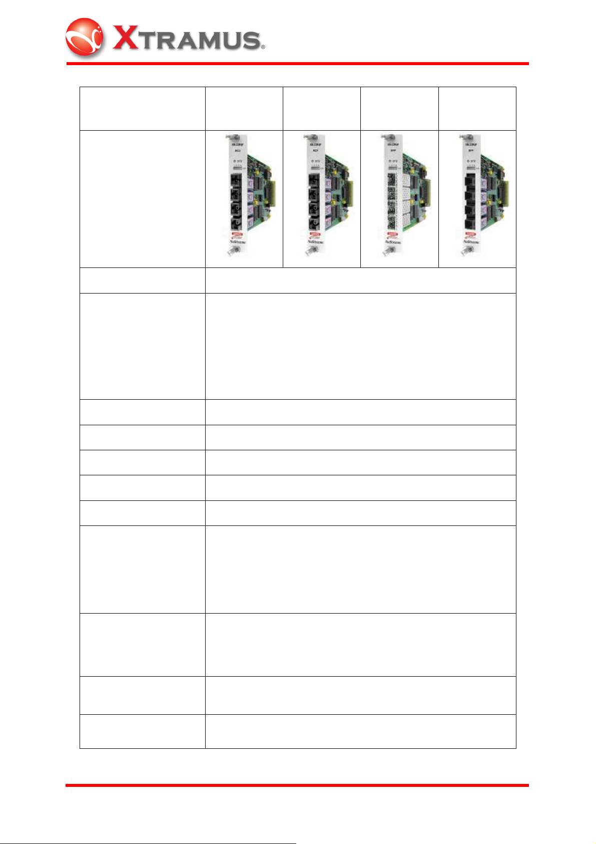
Model XM-22R4F
WCO
Photo
Test Port 4
WCO: 155Mbps Bi-direction SC receptacle single fiber
transceiver, Tx1550, Rx1310
WCP: 155Mbps Bi-direction SC receptacle single fiber
Interface
transceiver, Tx1310, Rx1550
SFP: User-selectable 100 Base-X SFP transceiver
SFF: 100Base-X Fiber transceiver in 2x5 package style
XM-22R4F
WCP
XM-22R4F
SFP
XM-22R4F
SFF
Speed 100 Mbps Fiber
CPU MPC852T
Preamble 4 ~ 16 Bytes
Frame Length 48 ~ 2,036 Bytes: Fixed /Increase /Decrease /Random /Loop
Transmit Mode Single /Burst /Multi Burst /Continuous
100 Mbps: 480 ns ~ 2 sec
Control: fixed/ random
Inter-frame Gap
Unit: Packets/Sec, %Utilization, Bit Time, Line Rate,
Databits/Sec, Frame bits/Sec, Total bits/Sec, nSec, uSec,
mSec, Sec
0055, AA, 55 AA, 5A 5A, FF FF, 8-0’s 8-F’s, 16-0’s 16-F’s,
Data Pattern
32-0’s 32-F’s, 64-0’s 64-F’s, Random, Incrementing byte,
Incrementing word, Decrementing byte, Decrementing word;
Custom
Error Generation
CRC Error, Alignment Error, Dribble Error, IP Checksum
Error
Data Integrity
Yes
Verification /Sequence
XTRAMUS TECHNOLOGIES
®
18
E-mail: sales@xtramus.com
Websi t e: www.Xt ram u s.c om
Page 24

Checking
Source /Destination
MAC Address
Source /Destination
IP Address
IPv4 checksum
generation
Hardware Counters
Fixed /Increment /Decrement /Random
Variable fields can be set depending on UI, max length of
each field is 32-bit
Fixed /Increase /Decrease/Random
Hardware
TX Packet/Byte, RX Packet/Byte, Unicast, Multicast,
Broadcast,UDF Logic ,VLAN Packet ,MPLS Packet ,Pause
Packet ,IPv4 Packet ,IPv6 Packet ,TCP Packet ,CRC Error ,
DI Checksum Error, Serial Number Error ,Oversize Packet ,
Undersize Packet ,Fragment Packet ,Jabber Packet ,CAE
Packet ,IP Checksum Error ,TCP Checksum Error ,UDP
Checksum Error ,BERT Error ,64 Bytes ,64-127 Bytes ,128255 Bytes ,256-511 Bytes ,512-1023 Bytes, 1024-1518 Bytes
Trigger 1 ~ 8 ,Total Collision ,Single Collision ,Multi
Collision ,Excess Collision ,Late
Collision ,TxArpReq ,TxArpReply ,RxArpReq ,
RxArpReply ,TxICMPReq ,TxICMPReply ,RxICMPReq ,
RxICMPReply
VLAN (VLAN ID / COS
Field)
MPLS (Label/COS/
TTL Field)
Fixed /Increase /Decrease /Random
Fixed/ Increase/ Decrease/ Ramdom (No. of labels not
limited)
Flow Control Yes
Capture Buffer Size 8 MB per port (up to 104 k frames)
Capture Mode Event
All condition, CRC Erroe, DI Error, Serial No. Error,
Capture Event
Alignment Error, IP Checksum Error, Trigger 1~8, Trigger
Logic, Any Defined Packet Size
QoS Testing Up to 8 Priority Queues
Line Performance Wire Speed
Please note that the module card can be removed with that slot being powered off in
NuStreams-2000i. Or shut down the chassis before plugging/unplugging any module
cards.
XTRAMUS TECHNOLOGIES
®
19
E-mail: sales@xtramus.com
Websi t e: www.Xt ram u s.c om
Page 25
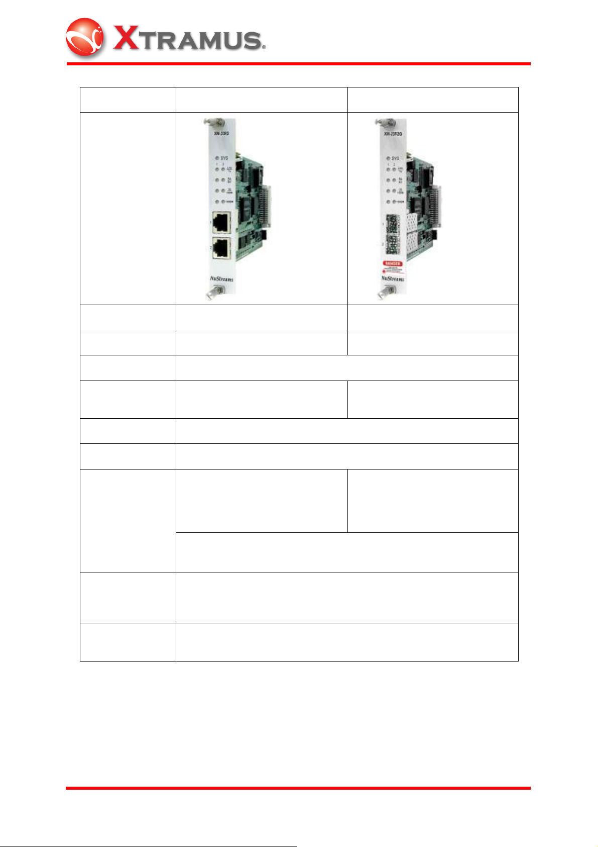
Model XM-23R2 XM-23R2G
Photo
Test Port 2 2
Interface RJ-45 Mini-GBIC
CPU MPC352T
Speed and Mode
10/100 Mbps: Half /Full Duplex;
1000 Mbps: Full Duplex
1000Mbps: Full Duplex
Preamble 4 ~ 16 Bytes
Frame Length 48 ~ 8,192 Bytes: Fixed /Increase /Decrease /Random
Control: Fixed /Random
(10 Mbps: 4800 ns ~ 13.42 sec;
Control:Fixed/Random
(1000 Mbps: 48 ns ~ 0.2 sec)
100 Mbps: 480 ns ~ 1.342 sec;
Inter-frame Gap
1000 Mbps: 48 ns ~ 0.2 sec)
Unit: Packets/Sec, %Utilization, Bit Time, Line Rate, Databits/Sec,
Frame bits/Sec, Total bits/Sec, nSec, uSec, mSec, Sec
All zeros, All ones, 55, AA, 55AA, 5A5A, 00FF, 0000FFFF, 8-0’s 8-
Data Field
F’s, Fixed /Increase /Decrease /Random in byte or in word; User
defined;
Error Generation
XTRAMUS TECHNOLOGIES
No CRC, CRC Error, Alignment Error, Dribble Error, IP Checksum
Error
®
20
E-mail: sales@xtramus.com
Websi t e: www.Xt ram u s.c om
Page 26

Data Integrity /
Sequence
Checking
Yes
Source /
Destination
MAC Address
Source /
Destination
IP Address
IP/TCP
Generation/
Analysis
Hardware
counters
VLAN (VLAN ID /
COS Field)
MPLS(Label,
COS, TTL Field)
Fixed /Increase /Decrease/Random
Variable fields can be set depending on UI, max length of each field
of 48-bit
Fixed /Increase /Decrease/Random
Hardware
TX Packet/Byte, RX Packet/Byte, Unicast, Multicast, Broadcast,
VLAN Packet, Pause Packet, CRC Error, DI Checksum Error, Serial
Number Error, Alignment Error, Oversize Packet, Undersize Packet,
Dribble Bit, IP Checksum Error, Trigger 1 ~ Trigger 8, Collision
TxArpReq, TxArpReply, RxArpReq, RxArpReply, TxICMPReq,
TxICMPReply, RxICMPReq, RxICMPReply
Fixed/ Increase/ Decrease/ Random
Fixed/ Increase/ Decrease/ Random (No. of labels no limited)
Flow Control Yes
Capture Buffer
Size
63 MB per port (up to 825k frames)
Capture Mode Event
Capture Event
DI Error, Serial No. Error, Alightmnet Error, IP Checksum Error,
Trigger 1~8, Trigger Logic, Any Defined Packet Size
QoS Testing Up to 8 Priority Queues
Line
Performance
Wire Speed
Please note that the module card can be removed with that slot being powered off in
NuStreams-2000i. Or shut down the chassis before plugging/unplugging any module
cards.
XTRAMUS TECHNOLOGIES
®
21
E-mail: sales@xtramus.com
Websi t e: www.Xt ram u s.c om
Page 27

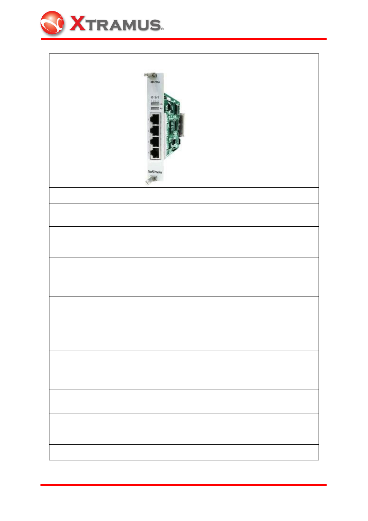
Model XM-2WL1
Photo
Interface
Power Source
Outlet Power Supply
Rating
1 IEC-320 C13 Inlet
Outlet: Universal adaptor
90 ~250 V AC, 30 ~ 80 Hz (±0.1%)
850 W
Power Consumption 110V: 4 Watt; 220V: 6 Watt
Internal breaker
Overload Protection
Software: Alarm Threshold Setting
RMS Voltage, RMS Current, Active Power, Apparent Power,
Dection Measure
Power Factor, AC Frequency, Temperature, Peak Voltage,
Peak Current
Device Control Power off/ Power on/ Cycle Reboot
Cycle Reboot Config. Burst/ Continue/ Multi-Burst
Crossing Mode 0 Degree/ 90 Degree/ 180 Degree/ 270 Degree/ Free Run
Report Format History log/ Instant display
Operating Temperature
0 ℃~ 45 ℃(32℉ ~ 113℉)
Humidity 10 %~90 % RH (Non-condensing)
XTRAMUS TECHNOLOGIES
®
22
E-mail: sales@xtramus.com
Websi t e: www.Xt ram u s.c om
Page 28

Please note that the module card can be removed with that slot being powered off in
NuStreams-2000i. Or shut down the chassis before plugging/unplugging any module
cards.
XTRAMUS TECHNOLOGIES
®
23
E-mail: sales@xtramus.com
Websi t e: www.Xt ram u s.c om
Page 29
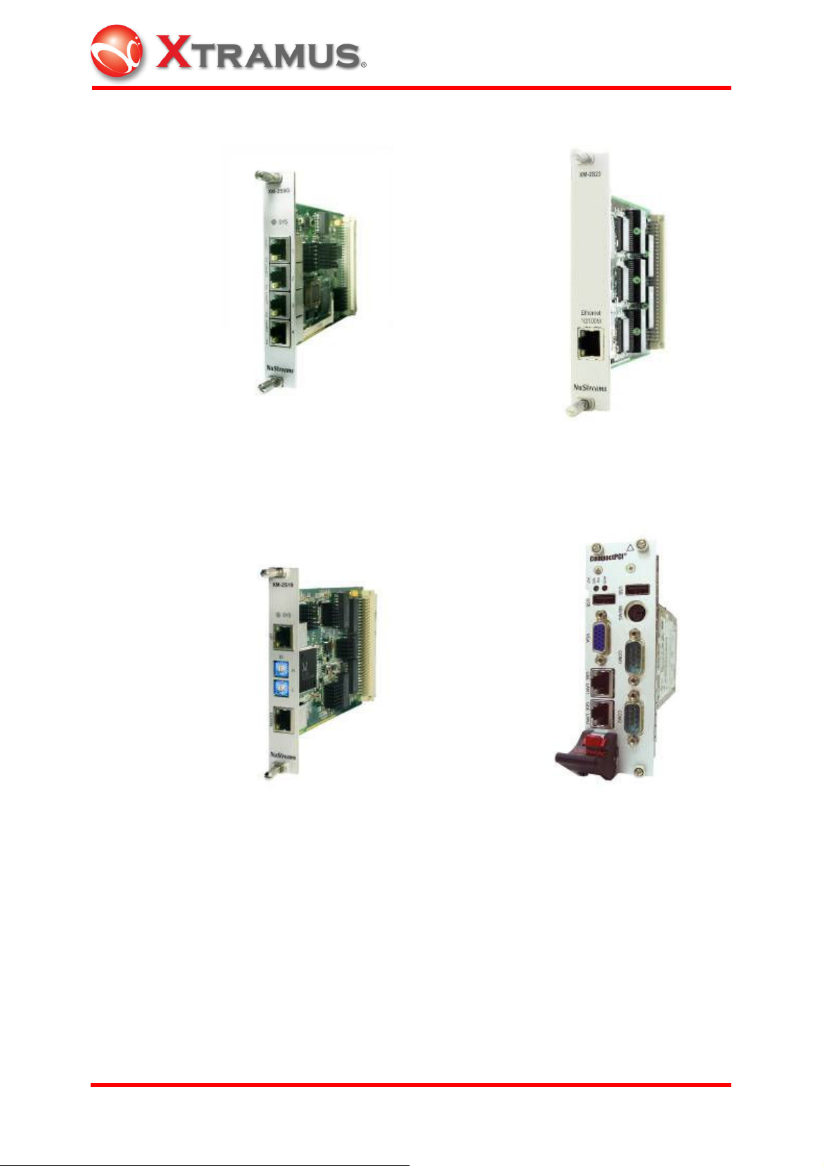
XM-2S8G
(NuStreams-2000i Internal Switch Module)
XM-2S23
(NuStreams-600 Internal Switch Module)
XM-2S19
(Module card element collection module)
XM-2113C
(NuStreams-2000i Built-in IPC)
THE IPC RISKS EXPLOSION IF
BATTERY IS REPLACED BY AN
INCORRECT TYPE. FOLLOW
INSTRUCTIONS TO DISPOSE OF USED
BATTERIES.
XTRAMUS TECHNOLOGIES
®
24
E-mail: sales@xtramus.com
Websi t e: www.Xt ram u s.c om
Page 30

XM-2000i
(NuStreams-2000i Backplane)
XM-600
(NuStreams-600 Backplane)
2.1.3 Changing Filters
2.1.3.1 NuStreams-2000i
Remove the front bracket.
XTRAMUS TECHNOLOGIES
®
25
E-mail: sales@xtramus.com
Websi t e: www.Xt ram u s.c om
Page 31

Change the black filter every year.
2.1.3.2 NuStreams-600
Remove the bottom bracket and open it. Change the black filter every year. Change
filters more frequently if working environment is unclean.
XTRAMUS TECHNOLOGIES
®
26
E-mail: sales@xtramus.com
Websi t e: www.Xt ram u s.c om
Page 32

2.1.4 Port Hardware
The ports on the NuStreams card modules which plug into the NuStreams Chassis
provide high-speed sophisticated transmit, capture and statistics operations.
2.1.4.1 Matrix
1 to 1024 packets can be sent as a batch repeatedly with Ethernet packet, CRC Bit,
CRC Error, Alignment Error, Packet Length and Preamble Length configuration.
2.1.4.2 Packets
Packets may contain a counted number of frames or a continuous set of frames when
Continuous mode is used. Frames are separated by programmable Inter-Packet Gaps
(IPG). The size of the Inter-Packet Gaps depends on the particular NuStreams module
in use. The placement of Inter-Packet Gaps is shown below:
Counted of Infinite (for Continuous packets)
2.1.4.3 Frame Data
The contents of every packet are programmable in terms of structure and data content.
The programmable fields are:
Preamble size—depends on the particular NuStreams card module used.
Frame size—depends on the particular NuStreams card module used.
Destination and Source MAC Addresses—allows the MAC addresses to be set to
a constant or vary randomly or increment/decrement under a mask.
Data generators—five different data generators are available. The generators are
listed below; the values from later generators overwrite data from earlier ones.
• Protocol related data—formatted to correspond to particular data link, transport
and protocol conventions. Data link layer controls allow for Ethernet II and
802.3 SNAP formatting, with support for VLANs. Protocol specific data for
XTRAMUS TECHNOLOGIES
®
27
E-mail: sales@xtramus.com
Websi t e: www.Xt ram u s.c om
Page 33

formatting ARP, IP and IPX packets (such as source and destination IP address)
is also supported.
• Data patterns—either pre-defined patterns up to 2k bytes in length, randomly
generated data or algorithmically generated data.
• DA/SA and DIP/SIP configuration is provided. By choosing between VLAN Tag,
MPLS Tag, MPLS Tunnel Tag, offset can be set through the window TxUDF. Or,
if the user defined is chosen, offset value can be configured. Various items can
be chosen individually or simultaneously through the window of MPLS or VLAN
Setup.
• Frame Identity Record (FIR)—an identity record stored at the end of the packet.
The information is very useful for determining the source of transmitted data
found in capture buffers.
• Frame Check Sequence (FCS)—the checksum for packets may be omitted,
formatted correctly or inserted with deliberate errors. Deliberate errors include
incorrect checksum, dribble errors, and alignment errors.
XTRAMUS TECHNOLOGIES
®
28
E-mail: sales@xtramus.com
Websi t e: www.Xt ram u s.c om
Page 34

2.2 NuStreams Software
2.2.1 NuWIN (NuStreams Window)
NuWIN is an interactive GUI-based software interface, which allows all features of the
NuStreams hardware to be programmed and operated. The programming paradigm
calls for each port to be individually set up, and included facilities for copying port
configuration from one port to others. A number of displays are available for viewing
captured packets, statistics and port latency.
2.2.1.1 Chassis Chain
Chassis Chain is a set of NuStreams chassis. The NuStreams chassis chain
corresponds to the hardware chain.
2.2.1.2 Chassis
Chassis is a single NuStreams chassis capable of holding different NuStreams module
cards. The ID of each chassis must be set (XM-2S19); the type of the chassis is
automatically discovered by the software (NuStreams-2000i). A chassis may hold any
mix of module cards.
2.2.1.3 Card
The types of cards loaded in a chassis and the appropriate number of ports are
automatically detected. Each port on a card has the same capabilities.
2.2.1.4 Port
The NuStreams port corresponds to an individual port on a NuStreams module card.
Each port is independently programmed in terms of its transmit, capture and statistics
capabilities. The NuStreams software shows four separate views for programming and
viewing operations:
Address Tables—sets up a range of MAC addresses for which the port will
respond to ARP requests and PING requests.
Packet Generator
XTRAMUS TECHNOLOGIES
®
29
E-mail: sales@xtramus.com
Websi t e: www.Xt ram u s.c om
Page 35

Packet Flows—defines the streams within stream regions and the contents of
packets.
Capture View—shows the data gathered during capture operations. Data is
displayed in raw form and interpreted for the corresponding protocols.
Counter Window—shows the real time statistics gathered during transmit and
receive operation.
2.2.1.5 Port Properties
A Port Properties dialog allows other port related properties to be programmed:
MII controls—low-level physical controls, such as 10 Mbps vs. 100 Mbps
operation and full duplex vs. half duplex.
Advanced MII controls—additional low level MII register controls.
Flow control—related to pause control operation.
Collision Backoff Algorithm—handling of collision situations.
Transmit mode—the choice of streams or flows for the port.
Forced Collisions—the generation of collision packets on receive ports.
2.2.1.6 Counter Window
Counter windows let users consider a set of ports at once. Select ports through the port
mapping function to view the counter windows for the assigned ports simultaneously.
In addition to NuWIN, individual manual for C++, an API, which allows programmers
conversant with the C++ programming language to control all applications of
NuStreams hardware operation, or other applications are also available.
XTRAMUS TECHNOLOGIES
®
30
E-mail: sales@xtramus.com
Websi t e: www.Xt ram u s.c om
Page 36

2.2.2 NuApps-2889
NuApps-2889 is a user-friendly Windows-based application software program
containing an enhanced GUI with real-time graphing. NuApps-2889 meets the testing
requirements in RFC-2285 and RFC-2889, including Forwarding Rate, Congestion
Control, Address Learning Rate, Address Caching Capacity, Errored Frame Filtering,
Broadcast Forwarding Rate, Broadcast Latency, and Forward Pressure. It generates
heavy bursts of multidirectional traffic with various protocols to test 10/100/100 Mbps
Ethernet networks.
2.2.3 NuAPI
NuAPI is an application programming interface provided for the development of
programs for MPT (Mass Production Testing) operations, which enhances efficiency
when running multiple tests on DUT. NuAPI includes Microsoft Visual C++ Library and
Borland C++ Builder Library. Xtramus provides the services of developing MPT
programs for the clients.
2.2.4 NuApps-2544
NuApps-2544 is a user-friendly and automated test suite based on industry-standard
RFC-1242 and RFC-2544 to analyze the performance of Ethernet switches, bridges,
and routers using NuStreams chassis. The multiple topologies supported by NuApps-
2544 and the load generation capabilities and the measurement accuracy of
NuStreams chassis provide users an effective way to accurately evaluate the
Throughput, Latency, Packet Loss, and Back-to-Back of a DUT or SUT in One-to-One,
One-to-Many, and Many-to-One configurations.
2.2.5 NuApps-ACPower
NuApps-ACPower is a practical and effective virtual panel to operate AC power monitor
and control module card XM-2WL1 in NuStreams chassis. The flexible interface helps
XM-2WL1 to collect long term power measurement information from the DUT in order
to be reviewed and alalyzed directly from an outlet power or remotely across a network
using NuStreams chassis.
XTRAMUS TECHNOLOGIES
®
31
E-mail: sales@xtramus.com
Websi t e: www.Xt ram u s.c om
Page 37

2.2.6 Multiple Users
1. Find a PC with 2 Network Interface Cards (NICs). The PC should be running
Windows- XP OS. This PC will be acting as the Server PC for NuServer (NuStreams
Server) later;
2. Connect one of the NIC (NIC-1) of the above PC to any one of the two ports on the
XM-2S19 module of the NuStreams-2000i chassis;
3. Connect the other NIC (NIC-2) of the above PC to an Ethernet Switch;
4. Open the "Network & Dial-Up Connection" under "Control Panel" of the Windows-
XP and find the connection icon corresponding to the NIC (NIC-1) attached to XM-
2S19. Select the "Property" of "Internet Protocol (TCP/IP)" and select "Auto Get IP" and
"Auto Get DNS". Once it's done, click on "O.K." and leave the setting window for NIC-1;
5. Find the connection icon corresponding to the NIC (NIC-2) attached to the Ethernet
Switch. Select the "Property" of "Internet Protocol (TCP/IP)" and set the IP, Subnet
Mask, and Gateway of NIC-2 in a way so that it's possible for it to communication with
other PCs connected to the same Ethernet Switch. After it's done, click on "O.K." and
leave the setting window for NIC-2;
6. Run NuWIN (i.e. NuStreams Window) program on the PC with 2 NICs;
7. Run NuWIN program on the remote PC (please note that the remote PC must be
runing Windows- XP OS).
XTRAMUS TECHNOLOGIES
®
32
E-mail: sales@xtramus.com
Websi t e: www.Xt ram u s.c om
Page 38

3. Installation
Unlike NuStreams-2000i, NuStreams-600 does not include PC. Before installing
NuWIN to the PC controlling NuStreams-600, connect the XM-2S23 Internal Switch
Module of the NuStreams-600 to the LAN port of the PC which users will be working on
through a UTP cable.
3.1 Starting NuWIN
1. Insert the CD-ROM containing NuWIN driver into the PC’s CD-ROM drive (If
AutoPlay is envoked, the installation starts automatically and skip step 2.)
2. Choose Start/Run and click Browse button, then the Browse window appears. In
the Browse window, select CD-ROM drive and autorun.exe file, then click Open.
3. Follow the on-screen prompts to complete the installation from top to bottom. The
files are copied to the directory specified by users (default C:\program
files\NuStreams\NuWIN)
3.1 Please note that in order to update NuWIN, the older version should be
uninstalled first beofre installing the newer one, otherwise NuWIN could not be
installed properly. Reboot the system after installing the new NuWIN.
3.2 At the start of NuWIN, if “cannot find the module” message appears, there must
be an old version of library not completely removed. Manually delete
C:\WINNT\System32\dclus*.bpl and reinstall the new version of NuWIN.
4. To update Firmware online, please go to Report/Card Version/Updates Firmware
through the popup menu of Chassis window or Tools/Option of the Main Menu Bar.
5. Check the Log Wndow to see if all the cards respond with an ACK signal in about
six minutes. If any of the cards fail to do so, check if its SYS LED indicator on the
front panel on the chassis is on.
6. Go to Report/Card Version of popup menu of Chassis window to verify the current
edition of Firmware/FPGA.
XTRAMUS TECHNOLOGIES
®
33
E-mail: sales@xtramus.com
Websi t e: www.Xt ram u s.c om
Page 39

4. Operating Procedure
4.1 Starting NuWIN
NuStreams chassis includes NuStreams-2000i and NuStreams-600. NuStreams-2000i
can function with or without an IPC.
Double-click on the NuWIN icon from desktop.
If the NuStreams-2000i is connected to a local server, click on the Yes button in the
Mode window, then the Network Interface Information window will appear. If the
NuStreams chassis is connected to a remote server, click on the No button, then the
Connect window will appear.
Choose the NIC to which users would like the NuStreams chassis to connect. Click OK
to activate NuServer.
XTRAMUS TECHNOLOGIES
®
34
E-mail: sales@xtramus.com
Websi t e: www.Xt ram u s.c om
Page 40

NuServer has been activated.
If the NuServer has already been activated, double-click on the NuWIN icon to
start operation.
The buttons in the Main window tool bar are described in the table below:
Figure Usage
Arranges all windows in cascade.
Arranges all windows vertically.
Arranges all windows horizontally.
Opens Counter window.
Opens Counter window to see selected ports.
Opens Counter Window Group to see grouped ports.
Opens Group window.
Opens Log window.
Releases unknown deadlock and opens system log on “.\\Log\\debug.log.”
XTRAMUS TECHNOLOGIES
®
35
E-mail: sales@xtramus.com
Websi t e: www.Xt ram u s.c om
Page 41

The Chassis Topology window will automatically appear when NuWIN is started. The
Chassis Icon stands for identity of the NuStreams chassis in use. Click on the desired
Chassis Icon for testing configuration. Right mouse click on the chassis icon to bring
out a popup menu.
Choose Invoke Chassis Virtual Panel to bring out the Chassis Panel. Most of the
testing configuration is conducted through the Chassis Panel.
The Chassis Panel represents a graphical image of the current NuStreams chassis
with all its installed cards.
XTRAMUS TECHNOLOGIES
®
36
E-mail: sales@xtramus.com
Websi t e: www.Xt ram u s.c om
Page 42

4.1.1 Main Window
The top level menus of NuWIN includes: File Menu, View Menu, Multiuser Menu,
Tools Menu, Window Menu, and Help Menu.
The choices for the File Menu are described in the table below:
Menu Choice Shortcut Usage
Load Ctrl+L Presents a dialogue for users to load workspace
from the disk.
Save Saves the current information to the current
workspace in use.
Save As Ctrl+A Presents a dialogue for users to save the current
workspace to the disk.
Exit Ctrl+E Exits NuWIN.
View Menu is divided into Control Menu and Report Menu. The choices for the Control
Menu are described in the table below:
Menu Choice Shortcut Usage
Debug Panel Ctrl+D Invokes Debug panel.
Debug panel is for debugging purpose of NuWIN.
Only authorized technicians from Xtramus have
access to this function.
Group Control
Widow
Chassis Topology
Window
Ctrl+G Invokes Group Control window (please see 4.20.1
for more information).
Ctrl+T Invokes Chassis Topology window (please see
4.20.2 for more information).
All Chassis Panel Ctrl+Alt+V Invokes all chassis panel.
Show NuServer Invokes NuServer when it is visible at the task
manage but invisible at the taskbar.
XTRAMUS TECHNOLOGIES
®
37
E-mail: sales@xtramus.com
Websi t e: www.Xt ram u s.c om
Page 43

The choices for the Report Menu are described in the table below:
Menu Choice Shortcut Usage
Counter Window Ctrl+W Invokes Counter window (please see 4.21.1 for more
information).
Group Counter
Window
Invokes Group Counter window (please see 4.21.2
for more information).
Group Window Ctrl+U Invokes Group window (please see 4.21.3 for more
information).
Log Window Ctrl+O Invokes Log window (please see 4.21.4 for more
information).
The choices for the Multi User Menu are described in the table below:
Menu Choice Shortcut Usage
Color Table
Invokes Color table for color information.
Port Status Invokes Port Status window (please see 4.21.5 for
more information).
Release My
Ownership
Release Partial
Releases current chassis (please see 4.2 for more
information).
Releases multiple module cards.
Slot(s)
Release All
Ownership
Reserve All
Chassis
Releases all chassis (please see 4.4 for more
information).
Reserves all chassis (please see 4.4 for more
information).
The choices for the Tools Menu are described in the table below:
Menu Choice Shortcut Usage
Option Ctrl+P Invokes Preference window (please see 4.21.6.3 for
more information).
XTRAMUS TECHNOLOGIES
®
38
E-mail: sales@xtramus.com
Websi t e: www.Xt ram u s.c om
Page 44

IFG Converter
Shortcut Config
Invokes IFG Converter for measurement conversion
of packet transmission.
Query Memory
Resource
Query Work Space
Resolution
Invokes Shortcut Configuration dialogue. In this case
the hotkey for the Reserve function of Chassis Panel
is set as “F7.”
Ctrl+M
Provides information regarding Memory Status.
Ctrl+R
Provides information regarding Resolution.
XTRAMUS TECHNOLOGIES
®
39
E-mail: sales@xtramus.com
Websi t e: www.Xt ram u s.c om
Page 45

Query Program
Running Duration
Provides information regarding duration from start.
Last Modification
Ctrl+Alt+L
Port
Provides information regarding the last modified port.
The choices for the Window Menu are described in the table below:
Menu Choice Shortcut Usage
Cascade Ctrl+S Arranges all windows in cascade.
Tile Horizontally Ctrl+H Arranges all windows horizontally.
Tile Vertically Ctrl+Y Arranges all windows vertically.
Minimize All Ctrl+I Minimizes All windows.
The choices for the Help Menu are described in the table below:
Menu Choice Shortcut Usage
Help F1 Invokes Help function.
Xtramus Web F3 Links to the official website of Xtramus
Technologies.
Packet View
Combination
F4
Shows all protocol combination.
XTRAMUS TECHNOLOGIES
®
40
E-mail: sales@xtramus.com
Websi t e: www.Xt ram u s.c om
Page 46

Shortcut List
About… Ctrl+B
Provides information regarding the Shortcut List.
Provides information regarding the current version of
NuWIN.
XTRAMUS TECHNOLOGIES
®
41
E-mail: sales@xtramus.com
Websi t e: www.Xt ram u s.c om
Page 47

4.2 Chassis Panel
The buttons in the Chassis panel tool bar are described in the table below:
Figure Usage
Reserves all ports for local users.
Releases all ports for local users.
Starts packets transmission through all ports.
Stops packets transmission through all ports.
Start the selected ports.
Stop the selected ports.
Sends Learning Packets.
Enables browse setup.
Enables multiple selection toggles.
Enables X-Trailer padding.
Disables X-Trailer padding.
Enables X-Trailer verification.
Disables X-Trailer verification.
XTRAMUS TECHNOLOGIES
®
42
E-mail: sales@xtramus.com
Websi t e: www.Xt ram u s.c om
Page 48

The LED indications in the Chassis panel are described in the table below:
Item Symbol/Color Description
N/A Card Type/ Card Number
N/A Slot Number
Orange/Green/Yellow/Blue 10M/100M/1G/10G
Green The port is linked.
Orange Half Duplex Mode
Green Full Duplex Mode
Flashing Green Frame transmission
Flashing Green Frame reception
Flashing Red Packet collision
Flashing Red Receiving packets with CRC
Checksum Error
Flashing Red Receiving Packet IP Checksum Error
Green Port selected
Gray Port unselected
Green with captured mode Under captured mode(selected)
Gray with captured mode Under captured mode(unselected)
Red Stop transmitting packets
Green Start transmitting packets
C Continuous packet transmission
S Single packet transmission
B Burst transmission
M Multiple-burst transmission
F Fixed packet length
I Increase packet length
D Decrease packet length
R Random packet length
XTRAMUS TECHNOLOGIES
®
43
E-mail: sales@xtramus.com
Websi t e: www.Xt ram u s.c om
Page 49

Before making testing configurations, click on the Reserve All button to reserve
entire chassis of individual cards.
The Message Box indicates the processing status of reserving all module cards.
If the chassis is shared by multiple users (up to 4 users can use one NuStreams
chassis at the same time), bring out the popup menu, choose Reserve/Reserve
Current Board or Reserve/Reserve(Multi Card) and make selection through the Port
Map to reserve the cards for one’s own use (please see 4.4 for more information).
To disable the reserve function, click on the Release All button . And the reserved
ports will all be released.
XTRAMUS TECHNOLOGIES
®
44
E-mail: sales@xtramus.com
Websi t e: www.Xt ram u s.c om
Page 50

4.3 Popup Menu
Move the cursor to any of the module cards on the Chassis panel and right mouse click
to bring out the Popup menu of the current port. In this case, the caption indicates the
menu describes the status of chassis 0, card 4, and port 2 of the chassis.
NuStreams chassis supports multiple module cards. Specific functions of the cards will
also be mentioned.
XTRAMUS TECHNOLOGIES
®
45
E-mail: sales@xtramus.com
Websi t e: www.Xt ram u s.c om
Page 51

XM-2301 XM-2301G XM-23L4 XM-23L4G
XM-28L1 XM-28L1CX4 XM-22R4 XM-22R4F
XTRAMUS TECHNOLOGIES
®
46
E-mail: sales@xtramus.com
Websi t e: www.Xt ram u s.c om
Page 52

XM-23R2 XM-23R2G XM-2WL1
XTRAMUS TECHNOLOGIES
®
47
E-mail: sales@xtramus.com
Websi t e: www.Xt ram u s.c om
Page 53

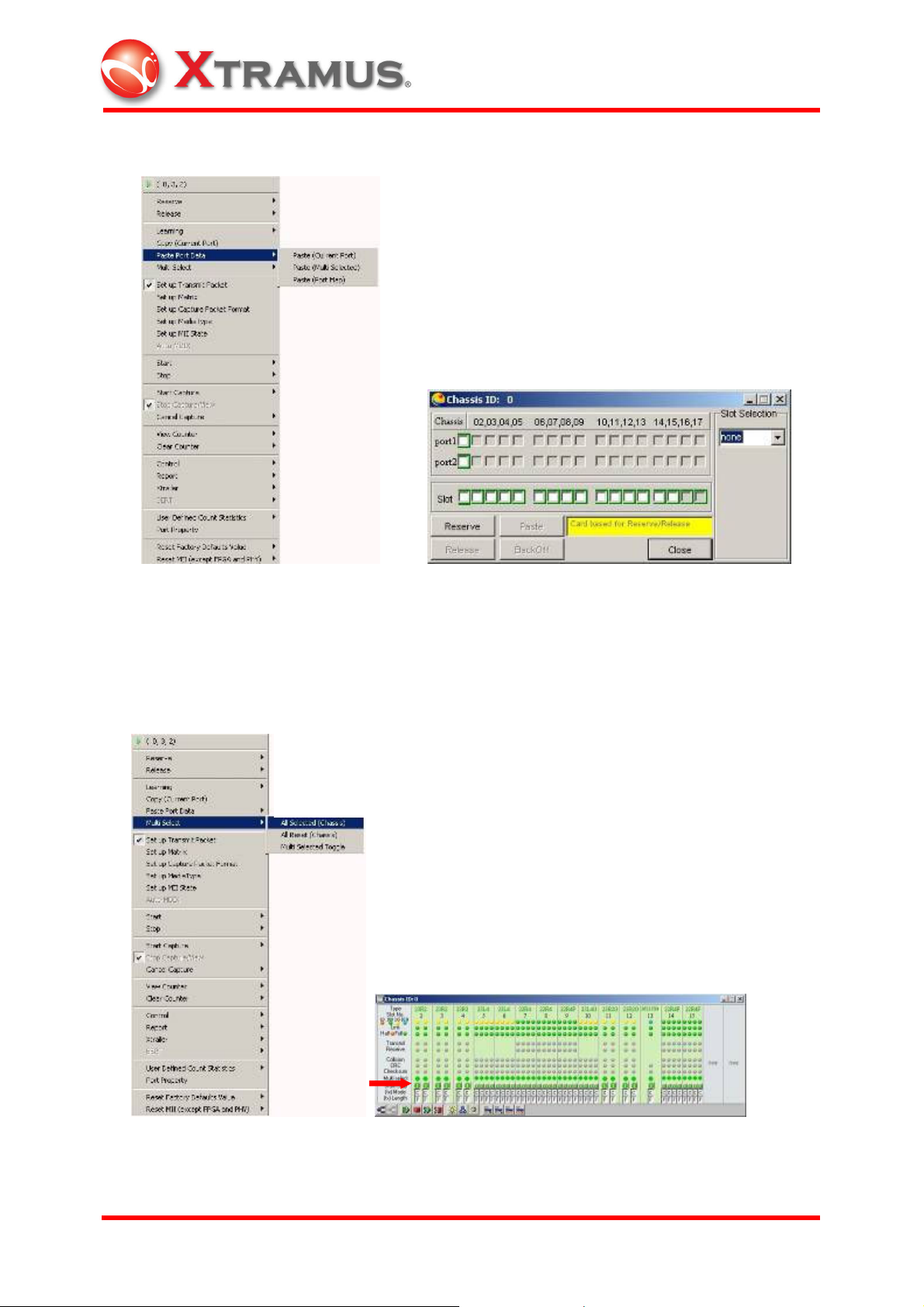
4.4 Reserve and Release
NuStreams chassis supports multiple users operation. Up to 4 users can share one
NuStreams chassis at the same time. Reserve the current card, multiple cards, or all
the cards in the chassis about to operate (left). Release the reservation of current card,
multiple cards, or all the cards in the chassis (right).
Choose Reserve (Multi Card) to bring out the Port Map (left). If users do not follow the
instruction to reserve all the ports/cards, the Reserve (Current Board) option will be
able to be chosen (right).
Reserve ports, cards, or type of cards with the Port Map.
XTRAMUS TECHNOLOGIES
®
48
E-mail: sales@xtramus.com
Websi t e: www.Xt ram u s.c om
Page 54

4.5 Learning
Choose Learning and its mode to enable the device under test (DUT) to create an
address table according to the source address in the received frame. If Current Port is
chosen, the address of current port will be built into the table. If Multi Selected is
chosen, the SAs of the selected ports will be built into the table. If Chassis is chosen,
the SAs of all the ports of the chassis will be built into the table.
Here is demonstration of this feature through port (0,4,2). Choose Modify Learning
Setup to bring out the Preference window.
XTRAMUS TECHNOLOGIES
®
49
E-mail: sales@xtramus.com
Websi t e: www.Xt ram u s.c om
Page 55

Choose Event Logging tab. Fill in the number of packets to be sent through the ports
chosen to be learned for building address table. In this demonstration, the number for
learning packet to be sent is 4.
Click on Learning (Current Port) to send Learning Packets through the current port.
The red light ball indicates the port is transmitting packets will show in a flash.
Choose port (0,4,1) and (0,4,2) to be viewed through the Counter window (click to
show the green balls).
XTRAMUS TECHNOLOGIES
®
50
E-mail: sales@xtramus.com
Websi t e: www.Xt ram u s.c om
Page 56

Choose Report/Counter Window (please see section 4.19 for more information) to
see the status of port (0,4,1) and (0,4,2). Port (0,4,2) has transmitted the 4 learning
packets and port (0,4,1) has received them.
XTRAMUS TECHNOLOGIES
®
51
E-mail: sales@xtramus.com
Websi t e: www.Xt ram u s.c om
Page 57

4.6 Copy Port Data
Copy the testing setup of the current card. Make further configurations by copying the
setting of frame length, inter-packet gap, inter-burst gap, stream control, padding,
transmission, media type, DA/SA, DIP/SIP, or all of the above of the current card.
XTRAMUS TECHNOLOGIES
®
52
E-mail: sales@xtramus.com
Websi t e: www.Xt ram u s.c om
Page 58
4.7 Paste Port Data
Paste the copied port data to the current port or to multiple ports through the Chassis
Window or the Port Map. Bring out the Port Map to paste the copied port data to the
designated ports, cards/slots or type of cards (slot selection).
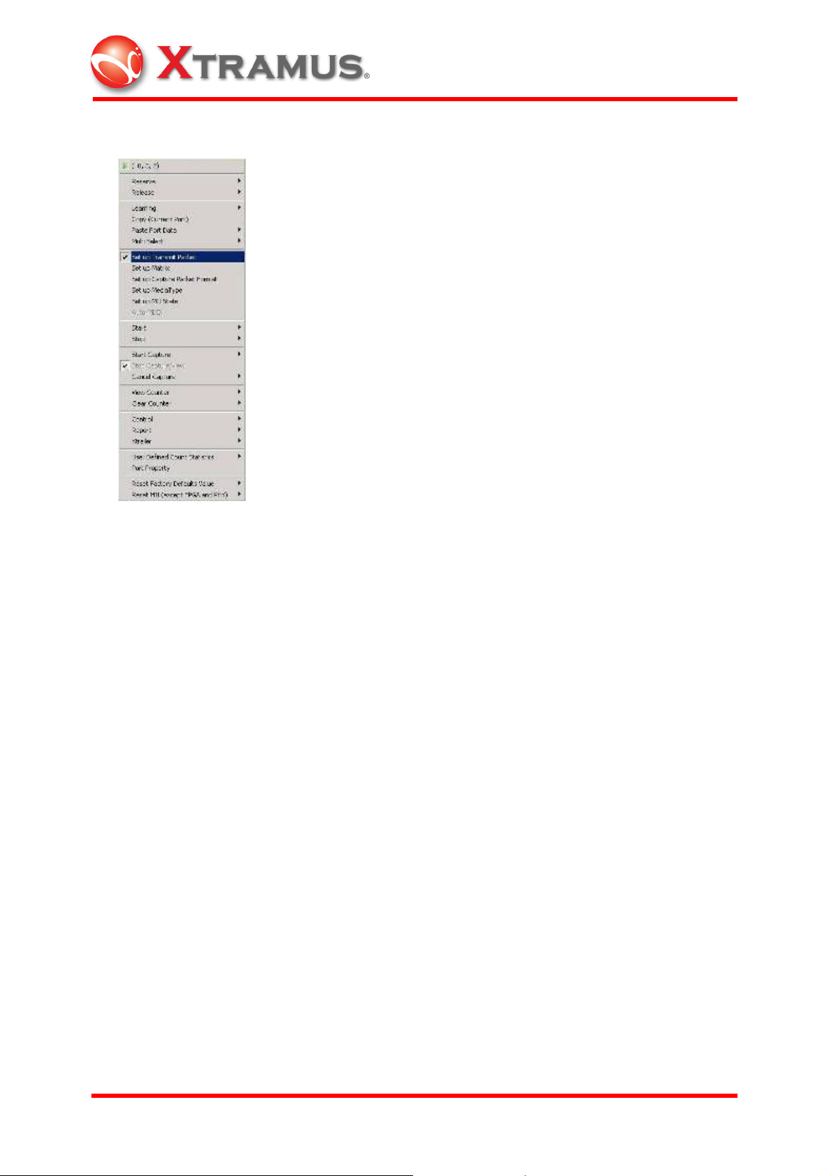
4.8 Multiple Selection
Choose All Selected (Chassis) to select all the ports in the chassis for testing
configuration.
XTRAMUS TECHNOLOGIES
®
53
E-mail: sales@xtramus.com
Websi t e: www.Xt ram u s.c om
Page 59

Choose All Reset (Current Chassis) to reset all the ports in the chassis.
Set some of the cards by clicking the LED indicators in the Chassis window.
Choose Multi Selected Toggle to toggle between the set ports and reset ones.
XTRAMUS TECHNOLOGIES
®
54
E-mail: sales@xtramus.com
Websi t e: www.Xt ram u s.c om
Page 60
4.9 Set up Transmit Packet
Choose Set up Transmit Packet to bring out the Transmit Setup window.
The Frame Data Setup provides the ability to control all aspects of packets transmitted
by the NuStreams Testing Systems. These frames are also referred as packets in
some contexts. Many frames may be generated in the processing of a stream; many of
the controls available allow the specification of a series of values applied to subsequent
frames.
XTRAMUS TECHNOLOGIES
®
55
E-mail: sales@xtramus.com
Websi t e: www.Xt ram u s.c om
Page 61

4.9.1 Frame Data Setup
The Frame Data is programmed by the following three types of data generators. They
are DA/SA, DIP/SIP, and Collision. The data created by each generator will overwrite
data created by earlier generators.
Select DA/SA, DIP/SIP, and Collision tab of the Frame Data dialogue to view their
individual property sheet.
4.9.1.1 Mask
Mask is a 6-byte (48-bit) value (in hexadecimal), which can be set to bind the range of
setting based on bit. The first two bytes are set to be fixed; the last four bytes can be set
as Mask value. The following table illustrates an example of XM-23L4 Mask fields
setting.
(Module Card: XM-23L4, DA: “0080 C8000501”, Mask: “XXXX XXXXXXXX”, Mode:
“Increase”, Loop count: ”10”, Loop step: “1”.)
XTRAMUS TECHNOLOGIES
®
56
E-mail: sales@xtramus.com
Websi t e: www.Xt ram u s.c om
Page 62

Bit Mask Editor Result
DA Mask (in 6 bytes) Masked DA Value
0080 C800 0501 (1)
XXXX XXXX XXXX (2) 0080 C800 0501 (3)
0080 C800 0502
0080 C800 0503
0080 C800 0504
0080 C800 0505
0080 C800 0506
0080 C800 0507
0080 C800 0508
0080 C800 0509
0080 C800 050A
0080 C800 0501
…
If DA mode is set as “Increase,” the following DA of user-defined packets would be
“0080 C800 0502,” “0080 C800 0503,” “0080 C800 0504,” etc., and bound by the Mask
field, the actual DA of user-defined packets would be “0080 C800 0502”, “0080 C800
0503”, “0080 C800 0504”, etc.
XTRAMUS TECHNOLOGIES
®
57
E-mail: sales@xtramus.com
Websi t e: www.Xt ram u s.c om
Page 63

4.9.1.2 Mode
Choose DA/SA/DIP/SIP mode setting for user-defined packets through Mode selection
of each dialogue.
1. Fixed stands for fixed (constant) pattern of all transmitted packets.
(000000000001, 000000000001, 000000000001…)
2. Increase stands for packets transmitted with incrementally increased value.
(000000000001, 000000000002, 000000000003…)
3. Decrease stands for packets transmitted with decrementally decreased value.
(000000000003, 000000000002, 000000000001…)
4. Random stands for packets transmitted with random value.
(000000000001, 000000000003, 000000000002…)
4.9.1.3 Loop
Loop Count indicates the number of transmitted packets in a loop, and Loop Step
indicates the difference between every transmitted packet in the loop. Loop Count and
Loop Step can be enabled for Increase and Decrease mode of DA/SA value setting.
Please note that for the Increase and Decrease mode of DIP/SIP setting, Loop Step
setting is not enabled.
XTRAMUS TECHNOLOGIES
®
58
E-mail: sales@xtramus.com
Websi t e: www.Xt ram u s.c om
Page 64

If the DA value is set as “00000000001(expressed in hexadecimal format),” the
transmission mode is set as “Increase,” the Loop Count value is set as “5,” and Loop
Step value is set as “1,” the transmitted packets under this configuration shown in the
Capture window will be like the following example:
00000000001
00000000002
00000000003
00000000004
00000000005
00000000001
.
.
.
If the mask value of this configuration is set as “XXXX 00000001(expressed in
hexadecimal format),” the actual reading on the Capture window will be:
00000000001
00000000000
00000000001
00000000000
00000000001
00000000000
.
.
.
XTRAMUS TECHNOLOGIES
®
59
E-mail: sales@xtramus.com
Websi t e: www.Xt ram u s.c om
Page 65

4.9.1.4 Padding and Pattern
Padding makes a complement for the user-defined packet with insufficient length.
When the actual transmitted packet length is less than the set value (please see
4.9.2.1 for Frame Length setting), the padding function will be enabled. The result of
packets with padding can be seen on the Capture window.
The factory default setting for padding is 00 (byte).
1. User defined frame: Inserted user defined frame.
2. Random: Inserted padding with random pattern
3. Increase in byte: Inserted byte with incremental increase (AA, AB, AC…)
4. Increase in word: Inserted word with incremental increase (AAAA, AAAB, AAAC…)
5. Decrease in byte: Inserted byte with decremental decrease (AC, AB, AA…)
6. Decrease in word: Inserted word with decremental decrease (AAAC, AAAB, AAAA…)
XTRAMUS TECHNOLOGIES
®
60
E-mail: sales@xtramus.com
Websi t e: www.Xt ram u s.c om
Page 66
4.9.1.5 Pattern Edit
In Transmit Setup window, choose user defined frame as the padding selection, click
Edit button to bring out the Bit Mask Editor for advanced editing of padding content or
a new packet. Key in the word or byte value. Choose Substitute the Entire UDF to
replace the entire original user defined packet with the padding setting or any new
packets.
XTRAMUS TECHNOLOGIES
®
61
E-mail: sales@xtramus.com
Websi t e: www.Xt ram u s.c om
Page 67

This is the Bit Mask Editor Window. Edit the padding content or the new packet and
click the OK button to apply the editing result.
The editing value can be loaded from files or network or saved as new files by clicking
on the Load From File or Save To File button.
XTRAMUS TECHNOLOGIES
®
62
E-mail: sales@xtramus.com
Websi t e: www.Xt ram u s.c om
Page 68

Click Set Data Length button on the Bit Mask Editor to set up the length of the
padding content or new packet to replace original ones.
XTRAMUS TECHNOLOGIES
®
63
E-mail: sales@xtramus.com
Websi t e: www.Xt ram u s.c om
Page 69
4.9.1.6 Capture and View Packet
Select and send packet through (0,4,1).
Choose Start Capture Mode to capture the packet received by (0,4,2). From the
Chassis panel, there is a small blue arrow shown on the slot four of the module card.
XTRAMUS TECHNOLOGIES
®
64
E-mail: sales@xtramus.com
Websi t e: www.Xt ram u s.c om
Page 70

Choose Start Capture/View to bring out the Capture window.
Choose the packet to be saved. It’s packet No.1 in this case. Click on the Export to
Raw Data button to save the binary data of the chosen packet as a default file with
extension “nhe.”
XTRAMUS TECHNOLOGIES
®
65
E-mail: sales@xtramus.com
Websi t e: www.Xt ram u s.c om
Page 71

The Save Data window will automatically appear when Export to Raw Data button is
clicked. Save the Raw Data file to any position preferred.
Go to Bit Mask Editor and click Load From File…
… to open nhe file previously saved.
XTRAMUS TECHNOLOGIES
®
66
E-mail: sales@xtramus.com
Websi t e: www.Xt ram u s.c om
Page 72

The binary data of the chosen packet are shown in the Bit Mask Editor.
Now the binary data of the chosen packet is shown on the pattern dialogue, which will
serve as a new packet to replace the original padding content. Make sure to select
User Defined Frame as the padding mode and Substitute the Entire UDF.
XTRAMUS TECHNOLOGIES
®
67
E-mail: sales@xtramus.com
Websi t e: www.Xt ram u s.c om
Page 73

4.9.1.7 TxUDF
Select TxUDF tab of the Frame Data dialogue to start customizing packet.
For example, to make packets with VLAN tag configuration in the UDF, choose Tag A
(VLAN) in the Protocol dialogue.
XTRAMUS TECHNOLOGIES
®
68
E-mail: sales@xtramus.com
Websi t e: www.Xt ram u s.c om
Page 74

Choose VLANTag in the Selection dialogue. Please note that the Offset value will
automatically change to 12 if VLANTag is chosen. Users may choose the desired
Mode and Loop count for the configured packet.
After setting, send the defined packet through the chosen port. In this case, it’s (0,4,1).
Move the cursor to port (0,4,2) on the chassis panel.
Choose Start Capture Mode and Stop Capture/View to view the packets received
through port (0,4,2).
Now the contents of the defined packets show with all the customized features
captured through port (0,4,2).
XTRAMUS TECHNOLOGIES
®
69
E-mail: sales@xtramus.com
Websi t e: www.Xt ram u s.c om
Page 75

To further configure user-defined packet with VLAN tag, go to the Protocol dialogue
and click on the Edit button to bring out (0,4,1) XM-2202 VLAN Setup window.
For other protocol variation supported by UDF function, choose the desired selection in
the Protocol dialogue. It’s MPLS in this case.
XTRAMUS TECHNOLOGIES
®
70
E-mail: sales@xtramus.com
Websi t e: www.Xt ram u s.c om
Page 76

Follow the previous procedure to set up MPLS configuration. Go to the Protocol
dialogue and click on the Edit button to bring out MPLS Setup window to further
configure user-defined packet with MPLS tag.
4.9.1.8 Collision
The Collision tab controls the setting of collision.
Backoff Count stands for the number of retry when collision occurs. 16 is the default
value for Backoff Count.
XTRAMUS TECHNOLOGIES
®
71
E-mail: sales@xtramus.com
Websi t e: www.Xt ram u s.c om
Page 77

Continuous stands for continuous retransmission. The back off random mask (random
amount of time waiting for retransmission) can be configured between 21 x 51.2 (slot
time) to 210 x 51.2 (slot time) ms.
Force collision can be activated when receiving packets. In addition to normal capture
operation, forced collisions can be generated at the receive end of 10/100 module ports,
but only when the port is in half duplex mode. The collision takes the form of a number
of nibbles generated at a specific offset within a packet. A number of consecutive
collisions are generated, followed by a non-colliding period. Please not that module
card XM-22R4 does not support force collision/late collision yet.
4.9.1.9. BERT
Please note that module card XM-28L1 only supports BERT on layer 1 and module
card XM-22R4 and XM-23R2 support BERT on layer 2. Choose the appropriate type by
clicking the radio button and input an offset value for test. The offset value should be
always at least 14 or larger. The settings of BERT in Set up Transmit Packet must be
exactly the same with the settings of BERT in Set up Receive Packet. If the settings
do not match, BERT error would occur.
XTRAMUS TECHNOLOGIES
®
72
E-mail: sales@xtramus.com
Websi t e: www.Xt ram u s.c om
Page 78
4.9.1.10 Loopback
Please note that only module card XM-22R4 supports this function. Choose either in
Layer-2 loop mode or in Layer-3 loop mode and then click OK button at the lower
part of the Transmit Setup window to complete setup.
The window would appear as the following once the loop mode is chosen.
Layer 2 refers to DA and SA settings while Layer 3 refers to IP settings. Global
Random Seed is a default value generated by hardware from ID of its corresponding
chassis, slot and port such as module card XM-22R4 at (0,10,1) with global random
seed of 5535.
XTRAMUS TECHNOLOGIES
®
73
E-mail: sales@xtramus.com
Websi t e: www.Xt ram u s.c om
Page 79

Layer 2:
Click Set up Transmit Packet> Frame Data> DA/SA- Layer2 loop mode at the
buttom.
Layer 3:
Click Set up Transmit Packet> Protocols> Ethernet II- IPv4- Layer3 loop mode
Once the setup is complete, the port can only be used as the receive port and can no
longer be the transmit port.
XTRAMUS TECHNOLOGIES
®
74
E-mail: sales@xtramus.com
Websi t e: www.Xt ram u s.c om
Page 80

4.9.2 Stream Control Setup
This section details the setting of Stream Control setup.
4.9.2.1 Frame Length (Without CRC)
The range for Preamble setting is from 4 to 16 bytes. For Length Control setting,
fixed, increase, random, and loop modes are provided. Each mode provides a range
(48 to 2036 bytes) to be set with.
For loop mode, another dialogue will appear for further setup. Up to 4 types of length
can be chosen for the setting.
XTRAMUS TECHNOLOGIES
®
75
E-mail: sales@xtramus.com
Websi t e: www.Xt ram u s.c om
Page 81

4.9.2.2 Streams Control Mode
For Stream control, packets are sent continuously (with gaps) in the continuous
mode. In the single mode, only one packet is sent. In the burst mode, a number of
packets are sent at once, and their number can be adjusted. In the Multi-burst mode,
multiple batches of packets will be sent, and the dialogue will stretch for further setup.
Up to 2
32
– 1 packets can be set for Packets per Burst, and up to 16,777,215 bursts
can be set for Bursts per Stream.
4.9.2.3 Transmit Control
X-Trailer appendage is not supported in default setting. Choose to enable it. CRC
Checksum can be chosen to remove its appendage. For error configuration, choose
desired errors in the Error Generation dialogue.
4.9.2.4 Inter-Frame Gap
XTRAMUS TECHNOLOGIES
®
76
E-mail: sales@xtramus.com
Websi t e: www.Xt ram u s.c om
Page 82

Multiple Units can be chosen for Inter-frame gap configuration. Different Rate will
show for different unit of the same value.
Click on button to see the Conversion table for all units.
Gap Control supports fixed and random mode. For random mode, the dialogue will
stretch for further setup.
XTRAMUS TECHNOLOGIES
®
77
E-mail: sales@xtramus.com
Websi t e: www.Xt ram u s.c om
Page 83
4.9.3 Protocol Setup
The Protocol tab controls the selection of protocols. NuWIN allows the initial bytes of
the packet contents to be formatted according to different conventions and protocols.
Please not that module card XM-22R4 or XM-23R2 only supports five types in
Ethernet Type of IPv4 Protocols as shown in the following picture.
XTRAMUS TECHNOLOGIES
®
78
E-mail: sales@xtramus.com
Websi t e: www.Xt ram u s.c om
Page 84

4.9.4 Transmit Header Operation
Transmit Header Operation is a powerful function to provide detailed variations
among DA, SA and TxUDF1~4 protocol parameters. Users could change TxUDF1~
TxUDF4 columns in Fixed, Increase, Decrease or Random mode by bytes. Only
module card XM-22R4 supports Transmit Header Operation, which could be
operatable through Set up Transmit Packet and Smart Matrix.
4.9.4.1 How to Set up Transmit Header Operation
6 parameters are divided into 2 groups to demonstrate DA /SA (Control Mode, Count
and/ or Step) and TxUDF1~4 Settings.
Part 1. Simple DA and SA settings:
Step 1. Click the desired port and click right mouse on Set up Transmit Packet.
Choose Protocols tab and select None in Data Link Layer dialogue.
Step 2. Click Transmit Header Operation button in the lower right corner to bring out
checked DA and SA as defaults in Fixed (F) mode.
XTRAMUS TECHNOLOGIES
®
79
E-mail: sales@xtramus.com
Websi t e: www.Xt ram u s.c om
Page 85

Step 3. Set up DA: Mode =I (Increase), Count =10, Step =2,
SA: Mode =D (Decrease), Count =15, Step =3
Step 4. Capture to compare packet data to determine whether expectations/ results are
being met /same.
XTRAMUS TECHNOLOGIES
®
80
E-mail: sales@xtramus.com
Websi t e: www.Xt ram u s.c om
Page 86
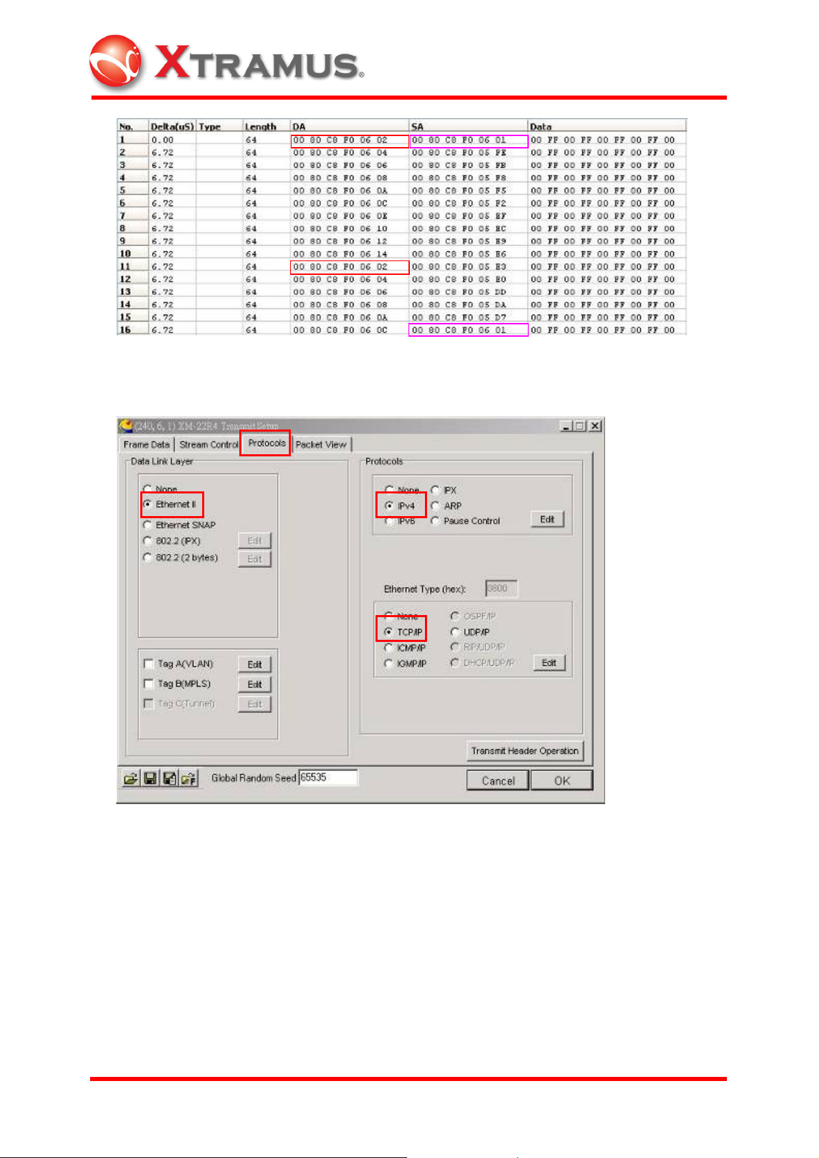
Part 2.Define TxUDF 1 ~ TxUDF 4
Step1. Select Protocols tab, and select Ethernet II – IPv4 – TCP/IP.
Step 2. Set up IP and TCP.
XTRAMUS TECHNOLOGIES
®
81
E-mail: sales@xtramus.com
Websi t e: www.Xt ram u s.c om
Page 87

Step 3. Click Transmit Header Operation to display tree diagram. Click right mouse
on the desired column to define TxUDF 1 ~ TxUDF 4 as SIP, DIP, Source Port and
Destination Port.
XTRAMUS TECHNOLOGIES
®
82
E-mail: sales@xtramus.com
Websi t e: www.Xt ram u s.c om
Page 88

Step 4. Set up TxUDF 1 and TxUDF 2: Mode =I (Increase), Count =10, Step =1,
TxUDF 3 and TxUDF 4: Mode =D (Decrease), Count =10, Step =1.
Step 5. Capture to compare packet data to determine whether results are the same.
XTRAMUS TECHNOLOGIES
®
83
E-mail: sales@xtramus.com
Websi t e: www.Xt ram u s.c om
Page 89

4.9.4.2 Set up and Operate in Smart Matrix
Trasmit Header Operation in Smart Matrix is similar to the operation in Transmit Setup.
Only the setting steps between these two are slightly different. The protocol parameters
are divided into 2 groups: DA/ SA and TxUDF 1~TxUDF 4.
Part 1. Simple DA and SA settings
Step 1. Click right mouse on desired port to select Set up Smart Matrix to bring out the
window. Choose the desired packet to check DA and SA in TxUDF to activate.
Check the box(es) to enable all TxUDF parmeters at once.
XTRAMUS TECHNOLOGIES
®
84
E-mail: sales@xtramus.com
Websi t e: www.Xt ram u s.c om
Page 90

Step 2. Click left mouse on No. column to turn blue in order to set up.
Step 3. Click right mouse on No. column to bring out menu to choose Setup TxUDF.
XTRAMUS TECHNOLOGIES
®
85
E-mail: sales@xtramus.com
Websi t e: www.Xt ram u s.c om
Page 91

Step 4. Open up tree diagram to click Destination to turn blue and click right mouse on
DA. Click Source to turn blue and click right mouse on SA to complete settings.
Step 5. Repeat Step 3 and 4 for DA and SA settings in Transmit Setup to complete the
whole configuration.
Part 2. Change TxUDF 1 ~ TxUDF 4 settings
Step 1. Click right mouse on desired port to select Set up Smart Matrix to bring out
menu. Choose desired packet to check TxUDF 1 ~ TxUDF 4 to activate.
XTRAMUS TECHNOLOGIES
®
86
E-mail: sales@xtramus.com
Websi t e: www.Xt ram u s.c om
Page 92

Step 2. Click Pattern to appear an extra button .
Step 3. Click Button to open protocol setup window.
XTRAMUS TECHNOLOGIES
®
87
E-mail: sales@xtramus.com
Websi t e: www.Xt ram u s.c om
Page 93

Step 4. Choose Frame Type and click TCP Protocol.
Step 5. Click left mouse on No. column to enable setup.
XTRAMUS TECHNOLOGIES
®
88
E-mail: sales@xtramus.com
Websi t e: www.Xt ram u s.c om
Page 94

Step 6. Click right mouse on No. column to bring out menu and choose Setup TxUDF.
Step 7. Open up tree diagram to select the desired column to turn blue. Click right
mouse on designated items to check TxUDF 1 ~ TxUDF 4 to complete settings.
XTRAMUS TECHNOLOGIES
®
89
E-mail: sales@xtramus.com
Websi t e: www.Xt ram u s.c om
Page 95

Step 8. Repeat Step 4 and 5 to set up DA and SA in Transmit Setup to complete.
4.9.5 Packet View Setup
Packet View tab controls the view of packets configured. The complete Ethernet
packet for the protocol configuration will be demonstrated in the Capture View window.
Packets are captured by the module cards for in-depth analysis. Specifications of
various protocols as well as packets contents are clearly displayed in hexadecimal and
ASCII format.
XTRAMUS TECHNOLOGIES
®
90
E-mail: sales@xtramus.com
Websi t e: www.Xt ram u s.c om
Page 96

4.10 Set up Matrix
Please note that only XM-2301(G) support this function.
Choose Set up Matrix to bring out the Matrix Setup window. Except from making user
defined packets through the Transmit Setup window (section 4.9), please use Matrix to
edit a series of packets with various combinations to be simultaneously transmitted.
The buttons in the Matrix Setup window toolbar are described in the table below:
Figure Usage
Loads default setting.
Loads from file.
Exports to Excel format.
Exports to Pattern Generation format.
Clears all setting.
Adds new frames.
Sets column width.
Loads from Sniffer .enc file
XTRAMUS TECHNOLOGIES
®
91
E-mail: sales@xtramus.com
Websi t e: www.Xt ram u s.c om
Page 97

Multi-Stream tool
Sets up TxUDF
Clears TxUDF.
Click on the button to invoke the factory default for Matrix setting. There are 10
packets designed in the Matrix default setting. Select packets for further configurations.
Or click on the button to load user-defined packet.
XTRAMUS TECHNOLOGIES
®
92
E-mail: sales@xtramus.com
Websi t e: www.Xt ram u s.c om
Page 98
If there is no user-defined packet, please capture packets through the capture window.
Click on the button to save the captured file as the Matrix file.
After clicking on the button, a message widow will appear for CRC padding
removal selection and the Export to Matrix Mode will show. Fill in the number of
customized packets desired.
Save the captured file as a Matrix file (with extension “mtx”).
Go back to the Matrix Setup window and click on the button.
XTRAMUS TECHNOLOGIES
®
93
E-mail: sales@xtramus.com
Websi t e: www.Xt ram u s.c om
Page 99

When Open window appears, open the saved Matrix file to load packets.
These captured nine packets in the saved Matrix file will show on the Matrix Setup
window. Choose packets through the Selected column for further configuration (CRC
Bit, CRC Error, Alignment Error, etc.)
XTRAMUS TECHNOLOGIES
®
94
E-mail: sales@xtramus.com
Websi t e: www.Xt ram u s.c om
Page 100

To edit packet pattern, click on the pattern of the exact packet and the button will
show. Click on the button to see the complete packet pattern.
This Frame Edit window for the chosen packet will appear for more configurations.
XTRAMUS TECHNOLOGIES
®
95
E-mail: sales@xtramus.com
Websi t e: www.Xt ram u s.c om
 Loading...