

Page 1

NuOutlet-LN
User’s Manual
USM Ver 1.1
Page 2

Foreword
Copyright
Copyright © 2010 Xtramus T e chnologies, all rights reserved. The information contained in this document is the property of Xtramus
Technologies. No part of this publication shall be reproduced, stored in a retrieval system, or transmitted, in any form or by any
means, without the prior written permission of Xtramus Technologies.
Disclaimer
The information contained in this document is subject to change without notice and does not represent a commitment on the part of
Xtramus Technologies. The information in this document is believed to be accurate and reliable. However, Xtramus Technologies
assumes no responsibility or liability for any errors or inaccuracies that may appear in the docume nt.
Trademarks
NuOutlet-LN, NuOutlet-WIN, NuDiscover are trademarks or registered trademarks of Xtramus Technologies. All other
trademarks and registered trademarks are the property of their respective owners.
Warranty
Xtramus Technologies warrants for the hardware provided along with this document under proper usage and conditions in normal
environment; any improper operation or in irregular environment may possibly cause this product NOT function well. For detailed
terms, please contact your local dealer.
Contact Information
Xtramus Technologies
E-mail: sales@xtramus.com
Website: www.xtramus.com
Tel: +886-2-8227-6611
Fax: +886-2-8227-6622
XTRAMUS TECHNOLOGIES®
2
E-mail: sales@xtramus.com
Website: www.Xtramus.com
Page 3

Revision History
Date Version History
2007/12/25 1.0 First version
1. Change manual format accordingly.
2010/12/17 1.1
2. Change NuOutlet-Win installation figures on page
14~15.
3. Change Device Control figure on page 32.
XTRAMUS TECHNOLOGIES®
3
E-mail: sales@xtramus.com
Website: www.Xtramus.com
Page 4

Table of Contents
Foreword..........................................................................................................................................2
Revision History..............................................................................................................................3
1. NuOutlet-LN Packet Accessories...........................................................................................5
2. Safety Instructions ..................................................................................................................6
2.1 Overload Protection..........................................................................................................6
2.1.1 Software........................................................................................................................6
2.1.2 Internal Breaker ...........................................................................................................7
2.1.3 Power Fuse...................................................................................................................7
2.2 Booting/Startup Time........................................................................................................7
3. Product.....................................................................................................................................8
3.1 Description.........................................................................................................................8
3.2 Upgrading Firmware........................................................................................................12
4. Software..................................................................................................................................13
4.1 Installation........................................................................................................................13
4.2 Uninstalling......................................................................................................................16
4.3 Updating Software...........................................................................................................18
5. Basic Usage ...........................................................................................................................19
5.1 NuDiscover.......................................................................................................................19
5.2 NuOutlet-LN Window.......................................................................................................20
5.3 NuOutlet-LN Information.................................................................................................21
5.4 Username and Password................................................................................................22
6. Connecting the Device..........................................................................................................23
6.1 Cable Connection............................................................................................................ 23
6.2 Discovering Devices .......................................................................................................24
7. Functions ...............................................................................................................................25
7.1 Setting IP address...........................................................................................................25
7.2 Reporting..........................................................................................................................27
7.2.1 Interval Setting...........................................................................................................27
7.2.2 Show Statistics ..........................................................................................................28
7.2.3 Alarms.........................................................................................................................30
Alarm Setting..........................................................................................................30
Alarm Report..........................................................................................................31
7.3 Chart Color Setting..........................................................................................................32
7.3.1 Power Measurement..................................................................................................32
7.3.2 Device Control ...........................................................................................................34
7.3.3 Colors .........................................................................................................................36
7.3.4 Vertical and Horizontal Axes.....................................................................................37
Vertical Axis............................................................................................................37
Horizontal Axis.......................................................................................................37
7.4 Saving and Loading Log Files........................................................................................38
7.4.1 Auto Save ...................................................................................................................38
7.4.2 Manual Save...............................................................................................................38
7.4.3 Loading Log Files......................................................................................................39
7.5 Saving and Loading Configuration Files.......................................................................41
7.5.1 Save ............................................................................................................................41
7.5.2 Load ............................................................................................................................41
8. Default Settings .....................................................................................................................42
9. NuOutlet-LN Specifications..................................................................................................43
XTRAMUS TECHNOLOGIES®
4
E-mail: sales@xtramus.com
Website: www.Xtramus.com
Page 5
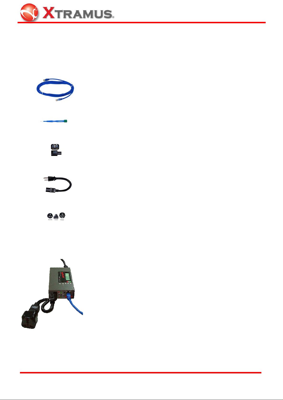
1. NuOutlet-LN Packet Accessories
NuOutlet-LN comes with the following items to connect it to a DUT (Device under Test).
Accessory Image Accessory Name Description
Cat. 5 cable
Connect this between the NuOutlet-LN and
a RJ45 socket.
The screwdriver is supplied to help with
Screwdriver
turning the Chassis ID and Slot ID dials.
Use the socket adaptor to change the
female end of the short cable into an
Socket adaptor
international socket. This is used to change
the DUTs power connector.
The short power cable is attached to the
Short Power cable
outlet power socket of the NuOutlet-LN to
attach the socket adaptor in to.
Plug into the inlet power of the socket of the
Power cables
NuOutlet-LN for use in corresponding
countries.
Note: Socket adaptor and Short Power cable are not necessary and therefore not available in
Taiwan, United States or Japan.
Here is an illustration of how a NuOutlet-LN is connected to the
DUT.
XTRAMUS TECHNOLOGIES®
5
E-mail: sales@xtramus.com
Website: www.Xtramus.com
Page 6
2. Safety Instructions
2.1 Overload Protection
The NuOutlet-LN is fitted with 3 levels of protection to prevent the device being damaged in the
event of voltage changes.
1. Software
2. Internal breaker
3. Power Fuse
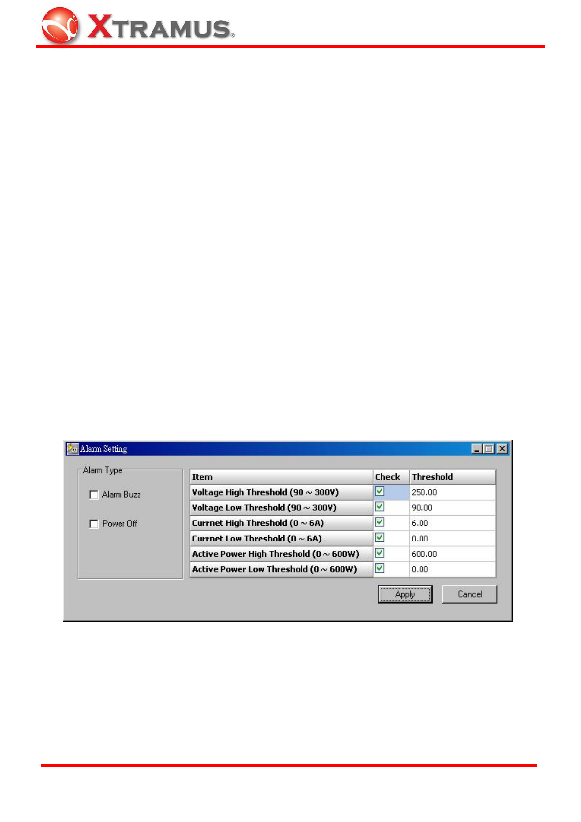
2.1.1 Software
The NuOutlet-LN Software allows the NuOutlet-LN to switch off if it exceeds the set thresholds.
To set the alarm threshold:
1. Open NuDiscover > Discover > Configure.
2. NuOutlet-LN Window > Report > Alarm Setting.
Click on the check boxes to include the alarm.
Manually enter the threshold value. The maximum and minimum threshold values are next to the
item names.
The alarm can either be audible or can switch off the device. Check Alarm Buzz for an audible
alarm or check Power Off to switch off the device.
XTRAMUS TECHNOLOGIES®
6
E-mail: sales@xtramus.com
Website: www.Xtramus.com
Page 7

2.1.2 Internal Breaker
The NuOutlet-LN is fitted with a breaker switch that will be activated when outlet power shortage
occurs.
2.1.3 Power Fuse
On the left of the device is a power socket, this socket contains a fuse. Use a flat head screw
driver to leave the fuse holder out and replace with a 250V/25Amp fuse.
2.2 Booting/Startup Time
Please run tests only after starting up NuOutlet-LN for at least 30 minutes for its best accuracy.
And also keep the environment in constant temperature during tests.
XTRAMUS TECHNOLOGIES®
7
E-mail: sales@xtramus.com
Website: www.Xtramus.com
Page 8
3. Product
3.1 Description
The NuOutlet-LN is designed for the collection of power parameters such as Vrms, Irms, active
power, power factor, peak voltage and peak current. These parameters can be checked and
analyzed directly from the outlet power of NuOutlet-LN or remotely across a network. The Outlet
Power function can be controlled directly or remotely across a network.
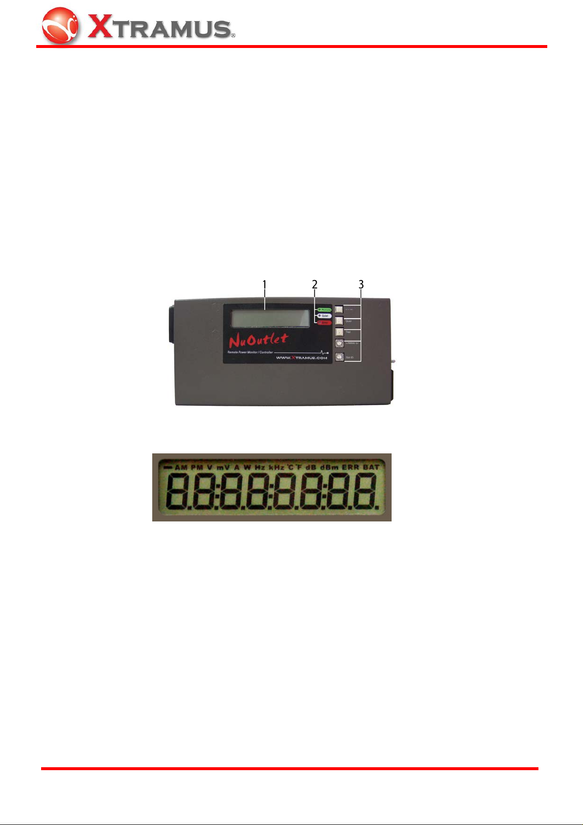
Below is a description of the functionality:
Front
1. LCD Display
The LCD display displays the status of the NuOutlet-LN, the following information can be
displayed: Power (Watts), Current (Amps), Voltage, Temperature (oC), Power Factor and
AC Frequency (Hz). IP address and Error codes are also displayed during performance
tests.
2. LED Lights
a) Remote – Turns bright green when remote login is successful. Flashes green when
Flash Device is pressed on the NuDiscover application.
b) Quiet – Turns bright green when pressing the quiet button; this silences the audible
alarm.
c) Error – Yellow when an error occurs.
XTRAMUS TECHNOLOGIES®
8
E-mail: sales@xtramus.com
Website: www.Xtramus.com
Page 9
3. Configuration Buttons
a) V.A.W. – Press this button to switch the display between Volts, Amps and Watts
and current operating temperature.
b) Quiet – (i) Silences the audible alarm.
(ii) Restores the default factory settings to DHCP IP mode. Press Quiet to
set DHCP mode and restore factory settings when Chassis ID and Slot ID
are both turned to F.
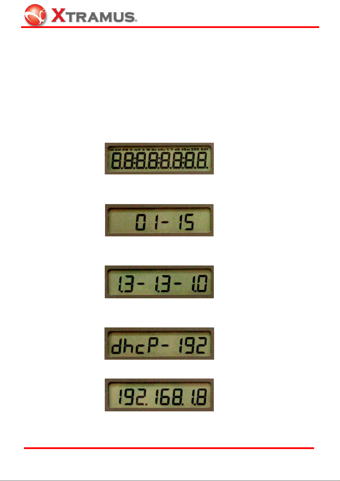
c) Test – (i) Tests the alarm and LCD display. (Auto test: shows chassis ID/ slot ID, all
version numbers and current IP address)
Auto test starts and LCD flashes,
first, chassis ID and slot ID display,
then all version numbers display,
and complete current DHCP IP address displays at last.
(ii) Restore default factory settings to Static IP mode. Press Test to view the
XTRAMUS TECHNOLOGIES®
DHCP displays,
9
E-mail: sales@xtramus.com
Website: www.Xtramus.com
Page 10
static IP "192.168.1.8" on the LCD and restores factory settings when
Chassis ID and Slot ID are both turned to F.
d) Chassis ID – Identify the device belonging to a specified NuStreams series on the
network, the range is #0~#E.
e) Slot ID – Identify which slot the specified NuStreams series device is in; the range is
#0~#E.
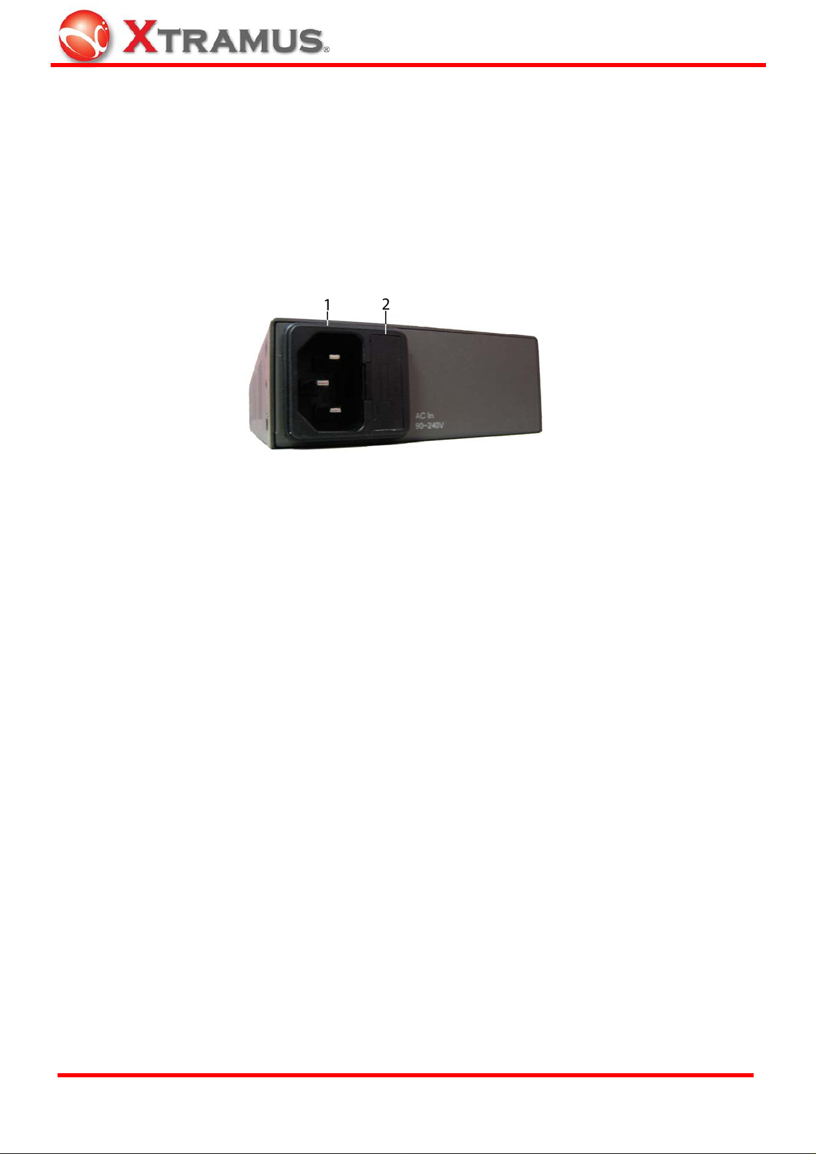
Left
1. Power Inlet – Plug the supplied power cable into this socket.
2. Fuse Holder – Holds a 250V/25Amp fuse which will blow if the current is exceeded.
XTRAMUS TECHNOLOGIES®
10
E-mail: sales@xtramus.com
Website: www.Xtramus.com
Page 11

Right
1. Outlet Power Supply – Plug in the power supply of the Device Under Test (DUT). The
power supply can be switched on and off either through switch or remotely across the
network.
2. Outlet Switch – Switches the outlet power on/off.
3. LED Lights
a) PWR – Green when the NuOutlet-LN has power.
b) SYS – Flashes green when the system is enabled.
Dark or Bright green means the system is abnormal.
c) Loading – Flashes green when a load is in the Outlet socket.
The higher the load, the faster the flashing.
d) Error –Bright yellow when there is a short circuit or an error occurs.
e) Outlet PWR –Bright green when the Outlet Power is on.
4. Reset button – Use a pointed object to reset the NuOutlet-LN to reboot the system with
the last saved configuration.
5. RJ45 10/100 Mb connector – Insert a category 5 cable into this socket.
a) Full – Bright orange when fully duplex.
b) Link/Act – Bright green when linked. Flashes green when transmitting and receiving
data.
XTRAMUS TECHNOLOGIES®
11
E-mail: sales@xtramus.com
Website: www.Xtramus.com
Page 12
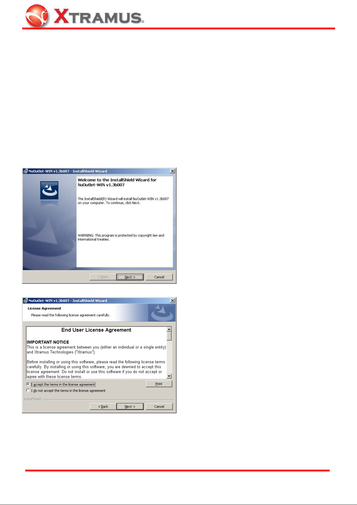
3.2 Upgrading Firmware
The firmware of the NuOutlet-LN can be updated by following the instructions below:
1. Check the hardware version Help > About > Hardware Version.
2. Check http://www.xtramus.com to see if updates are available.
3. Click on the File name to download and save it to the required directory.
4. Go to NuOutlet-LN Window > TFTP > Download Firmware.
5. Click on Browse to locate the downloaded file and click Download to install the firmware.
XTRAMUS TECHNOLOGIES®
12
E-mail: sales@xtramus.com
Website: www.Xtramus.com
Page 13
4. Software
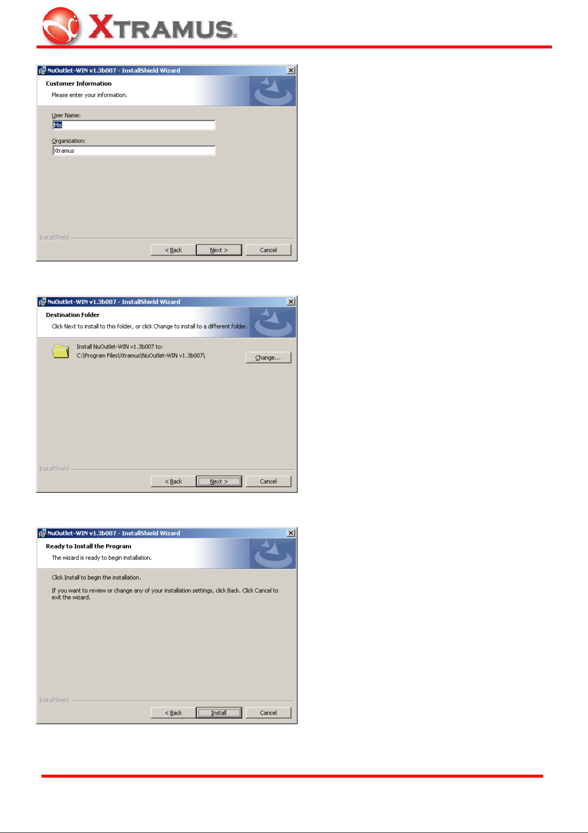
4.1 Installation
To configure the NuOutlet-LN, it is best to install the configuration software. Follow the instructions
below:
1. Insert the installation CD into the CD-ROM drive of the computer.
2. Follow the on-screen instructions and the images below.
Click Next to start installation.
1. Click the radio button to accept the
license agreement.
2. Click Next to insert the Customer
Information.
XTRAMUS TECHNOLOGIES®
13
E-mail: sales@xtramus.com
Website: www.Xtramus.com
Page 14
1. Enter the User Name and
Organization.
2. Click the radio button to select
current user or all users.
3. Click Next to continue.
Click Change if you would like to
change NuOutlet-WIN’s installation
path, or click Next to continue.
XTRAMUS TECHNOLOGIES®
Click Install to continue the
installation.
14
E-mail: sales@xtramus.com
Website: www.Xtramus.com
Page 15

The installation screen is displayed.
Once installation is finished, the
following screen is displayed. Click
Finish to close the window.
Two applications are installed, NuDiscover and NuOutlet-LN Window. NuDiscover is used to
recognize connected devices and NuOutlet-LN is used to configure the devices. The icons for
these devices are installed on the Windows desktop and in Programs > Xtramus > NuDiscover.
XTRAMUS TECHNOLOGIES®
15
E-mail: sales@xtramus.com
Website: www.Xtramus.com
Page 16

4.2 Uninstalling
If applications do not work correctly, it may be necessary to uninstall them.
1. Insert the installation CD into the CD-ROM drive of the computer.
2. Follow the on-screen instructions and the images below.
Click Next to start installation.
Modify – There are no modifications to
be made with the installation. If press
Next by mistake, press Back to return
to this screen.
Remove – Click this radio button and
then press Next to go to the next
screen.
XTRAMUS TECHNOLOGIES®
16
E-mail: sales@xtramus.com
Website: www.Xtramus.com
Page 17

Press Remove to uninstall the
applications.
The uninstallation is in progress.
Once uninstallation is finished the
following screen is displayed. Press
Finish to close the window.
XTRAMUS TECHNOLOGIES®
17
E-mail: sales@xtramus.com
Website: www.Xtramus.com
Page 18

4.3 Updating Software
Periodically Xtramus may update the NuDiscover and NuOutlet-LN Window software.
1. Before installing a new version of the software, the previous version must be uninstalled. Go to
Start > Programs > Xtramus > NuDiscover > Uninstall.
2. Download the software from http://www.xtramus.com.
From the directory the software has been saved to, click NuDiscover Setup and follow the
instructions above.
XTRAMUS TECHNOLOGIES®
18
E-mail: sales@xtramus.com
Website: www.Xtramus.com
Page 19

5. Basic Usage
5.1 NuDiscover
There are two ways to connect to the NuOutlet-LN:
1 – Directly through the NuOutlet-LN window if the IP address of the NuOutlet-LN is known.
2 – Through the NuDiscover application to find all NuOutlet-LN’s connected to the network.
When using the NuOutlet-LN, the first application to use is NuDiscover. This is used to find
devices and connect to them.
1
Discover – Look for devices.
2
Configure – Click to configure the
selected device.
3
Type – The type of device connected.
4
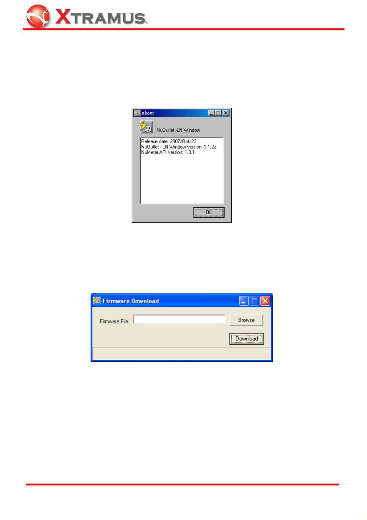
About – Display details of the
NuDiscover Window V ersion, Release
Date and NuDiscover API version.
5
Exit – Quit NuDiscover.
6
Name – Name of the connected
device.
7
IP Address – The IP address of the
connected device.
8
MAC Address – Display the MAC
address of the connected device.
9
Code Type – Display the firmware
type of the device
10
S/N – Display the serial number of the
connected device.
11
Flash Device – Click to flash the
selected device, the “Remote” LED
will flash. This is particularly useful
when more than one device is being
used.
12
Language – Options of language
interface.
XTRAMUS TECHNOLOGIES®
19
E-mail: sales@xtramus.com
Website: www.Xtramus.com
Page 20

5.2 NuOutlet-LN Window
The NuOutlet-LN Window is used to configure all NuOutlet-LN devices
1
Open – Open saved configuration
(.cfg) files.
2
File – Load and Save Configuration
files, load log file and exit the program
3
Save – Save configuration (.cfg) files.
4
System – Set device name, Set IP
configuration, Set user name and
password and reset to factory default.
5
Open Log Files – Open log (.csv)
files.
6
Control – Device control and Chart
color setting.
XTRAMUS TECHNOLOGIES®
7
Counter Chart – Display the counter
chart.
8
Report – Interval setting, Show
statistics, Alarm setting and Alarm
report.
9
TFTP – Download Firmware.
10
Help – Help and about.
11
NuOutlet-LN Information – Display
information on the connected device.
20
E-mail: sales@xtramus.com
Website: www.Xtramus.com
Page 21

5.3 NuOutlet-LN Information
1
Type – The type of device connected.
2
Name – Name of the connected device
3
IP Address – The IP address of the
connected device.
4
MAC Address – Display the MAC
address of the connected device.
5
Relay Count – Display the number of
times the outlet power being turned on
7
User Priority – Display who is logged
in Administrator or Guest.
8
Power Status – Turn green when the
on/off switch is switched on. Yellow
when cycle reboot. Grey when
switched off.
9
Outlet Power Status – When the
on/off switch is switched on this image
moves to ON and green, when the
switch is turned off this image moves
to OFF and red.
10
Connect Status – Turn green when
the device is connected, grey when
disconnected.
11
Language - Options of language
interface.
and off automatically or manually.
6
Code T ype – Display the firmware type
of the device.
XTRAMUS TECHNOLOGIES®
21
E-mail: sales@xtramus.com
Website: www.Xtramus.com
Page 22

5.4 Username and Password
The NuOutlet-LN comes with 2 available user settings:
1. Administrator – Gives full read and write access to the NuOutlet-LN. Default username = admin,
default password = admin (all lower case).
2. Guest – Gives read only access to the NuOutlet-LN. Default username = guest, default
password = guest (all lower case).
To change the password, follow the instructions below:
1. Press System > Set User Name and Password > Admin / Guest to see the following window.
2. Enter the Old password.
3. Enter the New password.
4. Press Apply.
Repeat the above instructions for changing the guest password.
XTRAMUS TECHNOLOGIES®
22
E-mail: sales@xtramus.com
Website: www.Xtramus.com
Page 23

6. Connecting the Device
6.1 Cable Connection
The NuOutlet-LN connects directly to the DUT. Follow the instructions below to ensure correct
connection.
1. Connect the NuOutlet-LN to the main power supply using the cable provided.
2. Connect a Cat. 5 cable and optional power cable from the NuOutlet-LN to the DUT.
3. Ensure that a computer is connected to the NuOutlet-LN and the NuOutlet-LN software is installed.
XTRAMUS TECHNOLOGIES®
23
E-mail: sales@xtramus.com
Website: www.Xtramus.com
Page 24

6.2 Discovering Devices
To start configuring devices, they must first be discovered; to do this, follow the instructions below:
1. Start the NuDiscover application from either the desktop icon or from Start > Programs
> Xtramus > NuDiscover > NuDiscover.
2. Press the Discover button. The NuOutlet-LN will search for available devices. If no available
devices are found, the following message will be displayed.
3. Click Yes to list a simulated version of a DUT or press No to close the message window and try
again.
4. If a device is listed, press Configure to open the NuOutlet-LN Window application.
XTRAMUS TECHNOLOGIES®
24
E-mail: sales@xtramus.com
Website: www.Xtramus.com
Page 25

7. Functions
7.1 Setting IP address
Each NuOutlet-LN is pre-configured with the following IP address [192.168.1.8]. To change this
address, follow the instructions below:
1. Load the NuOutlet-LN Window application from either the desktop icon or Start >
Programs > Xtramus > NuDiscover > NuOutlet-LN.
-
2. Enter the Administrator User Name (default is admin) and Password (default is admin) and press
Apply.
XTRAMUS TECHNOLOGIES®
25
E-mail: sales@xtramus.com
Website: www.Xtramus.com
Page 26

3. Once logged in, the following screen will be displayed.
4. Press System > Set IP Configuration and the following window is displayed.
Choose between Static and DHCP. If choosing Static, enter the new IP address in the IP
address section. Ask the network administrator for further details on configuring the
Subnet Mask and Gateway IP Address.
5. Press Apply to confirm the new details.
XTRAMUS TECHNOLOGIES®
26
E-mail: sales@xtramus.com
Website: www.Xtramus.com
Page 27

7.2 Reporting
7.2.1 Interval Setting
Intervals are the times between the points where data is gathered from the DUT. To access the
Interval Setting window, follow the instructions below.
1. Press Report > Interval Setting:
2. Enter the time (in seconds) between samples and press Apply.
The interval is displayed on the Statistics screen.
XTRAMUS TECHNOLOGIES®
27
E-mail: sales@xtramus.com
Website: www.Xtramus.com
Page 28

7.2.2 Show Statistics
The statistics screen is the most important screen in the NuOutlet-LN application. It displays all
information gathered from the DUT.
The following screen is shown by either:
1. Press Report > Show Statistics.
2. Press Show Statistics icon
.
XTRAMUS TECHNOLOGIES®
28
E-mail: sales@xtramus.com
Website: www.Xtramus.com
Page 29

1
Open – Open previously saved log
files in chart format
2
Save – Save files in .csv format to be
opened in either NuOutlet-LN or a
spreadsheet application
3
Load Scale File– Load previously
saved scale files in .scl format
4
Save Scale File– Save scale files
in .scl format
5
Play – Start data reception from the
NuOutlet-LN
6
Stop – Stop data reception from the
NuOutlet-LN
7
Clear Data Log – Clear all information
12
Exit – Quit the counter chart
13
V ertical Axis Scale – options of Nob
to turn manually or user- defined scale
with extended dialogue to define.
14
Nob – Zoom in and out of the chart
(Default 1V)
15
Horizontal Axis Scale – Zoom in/out
of the horizontal axis. (Default 1)
16
Move Selected Curve – Select a
power measurement (see below) and
chooses to move it up or down
17
Horizontal Axis Unit – Choose
whether to use Real Time or Elapsed
Time
18
Start Data Log Time – Display the
from the chart
8
Reset Chart – Reset chart information
to default settings
current date and time
19
Power Measurements – Choose
power parameters displayed on the
screen.
9
Refresh Alarm – Turn the alarm off
20
Graph – Display the captured
information
10
Alarm Light – Turn red when the
alarm has been activated
21
Cursor 1– A cursor used as an
indicator to help users gather the
related power parameters they are
interested in
11
Set Save Interval – Automatically
save current data at specified intervals
22
Cursor 2– Another cursor also used
as an indicator to help gather extra set
of power parameters.
A more detailed explanation of the above information is given below.
XTRAMUS TECHNOLOGIES®
29
E-mail: sales@xtramus.com
Website: www.Xtramus.com
Page 30

7.2.3 Alarms
Alarm Setting
When the alarm is activated, it can either emit a sound or, if the device is powered by the
NuOutlet-LN, switch the device off. Follow the instructions below to decide which to use:
1. Press Report > Alarm Setting.
2. Click in either Alarm Buzz for an audible alert or Power Off to switch off the device.
3. To silence the alarm, press the Quiet button on the NuOutlet-LN.
Note: Power Off is only functional if the device is powered by the NuOutlet-LN.
For any measured event, an alarm can be set. To change the alarm threshold values, follow the
instructions below:
1. Press Report > Alarm Setting.
2. To ensure that an event is being monitored, press the Check box.
3. To set a value that triggers the alarm, type that value into the Threshold field. The minimum and
maximum values are given next to the item name.
4. Press the Apply button to activate.
XTRAMUS TECHNOLOGIES®
30
E-mail: sales@xtramus.com
Website: www.Xtramus.com
Page 31

Alarm Report
When the alarm is detected, a report is generated; an example is shown below.
Alarm setting could be carried out by pressing Setting button, then Save Alarm Setting window
will popup as shown below.
The auto save function needs to be enabled before it comes into operation; to do this follow the
instructions below:
1. Check the Enable box.
2. Enter the save frequency in the interval field (default: 1800 seconds).
3. Press the Apply button.
XTRAMUS TECHNOLOGIES®
31
E-mail: sales@xtramus.com
Website: www.Xtramus.com
Page 32

7.3 Chart Color Setting
The counter chart is configurable so that its appearance and functionality can be altered for
individual preferences.
7.3.1 Power Measurement
By checking the Visible box next to the measurement description, the information shown in the
chart can be decided.
The chart above is divided into 8 fields (Instant, Cursor 1, Cursor 2, Delta, Average, S. Deviation,
Maximum and Minimum). These fields provide information on the values of the measurement:
Instant – The value at the last time point measured.
XTRAMUS TECHNOLOGIES®
32
E-mail: sales@xtramus.com
Website: www.Xtramus.com
Page 33

Cursor 1 – The value at the cursor 1 position. Click on any point in chart to change this value.
Cursor 2 – The value at the cursor 2 position. Press Shift button and click on any point in chart to
change this value.
Delta – The difference of the values between Cursor 1 and Cursor 2.
Average – The average of the values from the start to the current time.
S. Deviation – The standard deviation value measures how spread out the data is.
Maximum and Minimum – Maximum and minimum values from the start to the current time.
XTRAMUS TECHNOLOGIES®
33
E-mail: sales@xtramus.com
Website: www.Xtramus.com
Page 34

7.3.2 Device Control
NuOutlet-LN is capable of remotely controlling the power status and cycle reboot modes of the
DUT device.
1. Press Control > Device Control and the window is displayed.
2. Click the radio button to select the appropriate power status of the DUT.
a) Power Off – To set the DUT in power off status.
b) Power On – To set the DUT in power on status.
c) Cycle Reboot – To set the DUT in cycle reboot mode.
XTRAMUS TECHNOLOGIES®
34
E-mail: sales@xtramus.com
Website: www.Xtramus.com
Page 35

(i) Select Crossing Mode in different degrees or free run (any point) only in power on or off
status.
(ii) Click on Apply button to activate the crossing mode.
(iii) Click the radio button to select Cycle Reboot mode.
(iv) Set Cycle Reboot Configuration in Burst, Continue or Multi-Burst mode.
(v) Then enter power reboot interval (in seconds) and count values (in times) in the fields.
3. Press OK to apply all the changes you’ve made and exit Device Control window, press Cancel to
cancel all the changes you’ve made and exit, or press Apply to apply all the changes you’ve made
without closing the Device Control window.
Note: Power cycle reboot (relay count) can reach up to 100 times per second.
XTRAMUS TECHNOLOGIES®
35
E-mail: sales@xtramus.com
Website: www.Xtramus.com
Page 36

7.3.3 Colors
In the chart below, each measurement is represented by a different color for clarity.
The following selected and unselected curves can be different colors: Voltage, Current, Active
Power, Temperature, AC Frequency and Power Factor. The Chart Panel (Background), Axis, Grid
and 2 Cursors colors can also be changed. The selected and unselected curve widths can also be
chosen from the drop down lists.
1. Press Control > Chart Color Setting to see the window below.
2. Click the radio button to select the appropriate measurement line.
3. Press the Edit Color button to open the color palette.
4. Press Apply to change the chart color or press Default to return to pre-set colors. Press Cancel to
discard changes.
XTRAMUS TECHNOLOGIES®
36
E-mail: sales@xtramus.com
Website: www.Xtramus.com
Page 37

7.3.4 Vertical and Horizontal Axes
Vertical Axis
The vertical axis dial behaves like a zoom function, left click the mouse button to the desired scale
or hold down the left mouse button to turn the dial clockwise or counter-clockwise and see the
changes in real time. For example, see the differences in the images below.
1V (default) 10mV
As can be seen, the distance between voltages has increased to the 10mV image.
Horizontal Axis
The horizontal axis also provides a zoom function, giving greater detail for a specific point in time.
Either left click the mouse button to the desired scale or hold down the left mouse button to turn
the dial clockwise or counter-clockwise and see the changes in real time.
Scale 1 (default) Scale 10
As can be seen, the distance in time has been increased in the Scale 10 image.
XTRAMUS TECHNOLOGIES®
37
E-mail: sales@xtramus.com
Website: www.Xtramus.com
Page 38

7.4 Saving and Loading Log Files
7.4.1 Auto Save
The auto save function needs to be enabled before it comes into operation; to do this follow the
instructions below:
1. Press the Set Save Interval icon to see the window below.
2. Check the Enable box.
3. Enter the save frequency in the interval field (default value: 1800).
4. Press the Apply button.
7.4.2 Manual Save
Under the Counter Chart window, press the Save icon to save the current chart.
XTRAMUS TECHNOLOGIES®
38
E-mail: sales@xtramus.com
Website: www.Xtramus.com
Page 39

7.4.3 Loading Log Files
To load a previously saved chart, follow the instructions below.
1. Either a) Press File > Load Log File, b) Press the Open .csv file icon from the counter chart
window or c) Press the Load Log icon
2. Select the required file and press Open.
.
3. The window is displayed as figure in the next page.
XTRAMUS TECHNOLOGIES®
39
E-mail: sales@xtramus.com
Website: www.Xtramus.com
Page 40

4. 8 additional fields are displayed to load log files for more details.
1
Set Chart Title – Name a title for this
chart and also show in the chart.
2
Start Time – The start time of this log
file.
5
Save Scale – Save scale files in .scl
format.
6
Save Chart –Save files in .csv format
to be opened in either NuOutlet-LN or
a spreadsheet application.
3
End Time – The end time of this log
file.
4
Load Scale – Load previously saved
7
Reset Chart – Reset chart information
to default settings.
8
Exit – Quit this log file and exit.
scale files in .scl format.
XTRAMUS TECHNOLOGIES®
40
E-mail: sales@xtramus.com
Website: www.Xtramus.com
Page 41

7.5 Saving and Loading Configuration Files
The configuration of the current file can be saved and loaded. The configuration file contains the
following information:
a) Device Name
b) IP Addresses in Hex
c) Alarm control
d) Power controls
e) Voltage thresholds
f) Current thresholds
g) Actual power thresholds
h) Saving logs and intervals
i) Switch status
7.5.1 Save
To save the current configuration, press the icon or File → Save Configuration File.
7.5.2 Load
To load a previous configuration, press the icon or File → Load Configuration File.
XTRAMUS TECHNOLOGIES®
41
E-mail: sales@xtramus.com
Website: www.Xtramus.com
Page 42

8. Default Settings
The NuOutlet-LN can be reset to its default settings using the NuOutlet-LN Window:
Press System > Reset to factory default > DHCP Client mode or Static IP mode.
DHCP Client mode
Static IP mode
Or
Use a paperclip or pen to press the Reset button on the right side of the NuOutlet-LN. This resets
the device to the current settings.
XTRAMUS TECHNOLOGIES®
42
E-mail: sales@xtramus.com
Website: www.Xtramus.com
Page 43

9. NuOutlet-LN Specifications
NuOutlet-LN : AC Power Monitor and Controller
Model No. NuOutlet-LN
Connector 1 RJ45 Ethernet phone jack and 1 IEC-320 C13
INLET, 1 IEC-320 C20 OUTLET
Communication Ethernet
Network I/F 10/100Base-T with Full/Half duplex mode
Measure Detection Vrms AC, Irms AC, active power, power factor,
Vpeak AC and Ipeak AC
Security Username and Password with encryption
Security Level Dual Level, “Guest ” with switch on/off function,
“Admin” with all configuration parameters &
functions
Operation Mode Remote and Local with automatic configuration
Report Format History log or Instant display
Warning Information Auto reply packet for internet related connection,
Buzz
Switch Mode ON/OFF, Cycle Reboot
Switch Parameters Conditions of single or multiple events like
threshold, schedule, key word or sequential events
combination.
Display Segment characters with unit prompt abbreviation
LEDs
Expansion Cascaded through Ethernet port without amount
limitation
Protection Software, Fuse, Internal Breaker
Power Source 90~250V AC, 50~60 Hz
Power Consumption 5 W (110V/220V)
Outlet Power Supply
Rating
Case Dimensions 188.5 mm (L) x 86.8 mm (W) x 34.2 mm (H)
XTRAMUS TECHNOLOGIES®
600 W
43
E-mail: sales@xtramus.com
Website: www.Xtramus.com
Page 44

Weight Net Weight: 640g, Shipping Weight: 1450g
Operating Temperature 32oF to 113oF (0oC to 45oC)
Storage Temperature -40oF to 185oF (-40oC to 85oC)
Humidity 10%~90% RH
XTRAMUS TECHNOLOGIES®
44
E-mail: sales@xtramus.com
Website: www.Xtramus.com
Page 45

XTRAMUS TECHNOLOGIES®
45
E-mail: sales@xtramus.com
Website: www.Xtramus.com
Page 46

Note: Information and specifications contained in this document are subject to change without notice.
XTRAMUS TECHNOLOGIES®
All products and company names are trademarks of their respective corporations.
Copyright © 2010 Xtramus Technologies, all rights reserved.
Do not reproduce, redistribute or repost without written permission from Xtramus.
Doc # USM_NuOutlet-LN_V1.1_ENG_20101217
46
E-mail: sales@xtramus.com
Website: www.Xtramus.com
 Loading...