

Page 1

MCS-2160
Media Converter
User’s Manual
USM Ver 1.9.2
Page 2

Foreword
Copyright
Copyright © 2013 Xtramus Technologies, all rights reserved. The information contained in this document is the property of Xtramus
Technologies. No part of this publication shall be reproduced, stored in a retrieval system, or transmitted, in any form or by any
means, without the prior written permission of Xtramus Technologies.
Disclaimer
The information contained in this document is subject to change without notice and does not represent a commitment on the part of
Xtramus Technologies. The information in this document is believed to be accurate and reliable. However, Xtramus Technologies
assumes no responsibility or liability for any errors or inaccuracies that may appear in the document.
Trademarks
MCS-2160 is a trademark or registered trademark of Xtramus Technologies. All other trademarks and registered trademarks are
the property of their respective owners.
Warranty
Xtramus Technologies warrants for the hardware provided along with this document under proper usage and conditions in normal
environment; any improper operation or in irregular environment may possibly cause this product NOT function well. For detailed
terms, please contact your local dealer.
Contact Information
Xtramus Technologies
E-mail:
Website: www.xtramus.com
Tel: +886-2-8227-6611
Fax: +886-2-8227-6622
sales@xtramus.com
XTRAMUS TECHNOLOGIES®
2
E-mail: sales@xtramus.com
Website: www.Xtramus.com
Page 3
Revision History
Date Version History
2011/10/11 1.0 First draft version
1. Modifying XC-M667 figure. (Page 12)
2. Added new figure for MCS-FANT-05. (Page 24)
2011/11/04 1.1
2011/12/02 1.2
2012/01/10 1.3
2012/03/28 1.4
2012/04/23 1.5
3. Modifying new figure for Management interface. (Page
41-43)
4. Added new subject: “Port A/B SDFR Setting” and “Port
A/B Capture View”. (Page 49 and 50)
1. Updating MCS-2160 interface figure. (Page 36)
2. Updating System Information interface’s figure by adding
Syslog Info. (Page 37)
3. Updating System Information interface’s figure by adding
Syslog Info and descriptions. (Page 38)
4. Added Syslog Settings function and 3CDaemon
software’s functions descriptions. (Page 40~42)
5. Updating the Chassis Management interface and
descriptions. (Page 44)
6. Modifying the figure of Chassis Management. (Page 46
and 47)
7. Added Fan Tray interface (M) figure and description.
Added note for auto-refresh of Fan Tray Temperature.
(Page 45)
8. Updating Card Information interface figure, description
and note of auto-refresh for Temperature, Port
Wavelength and Factory. (Page 48)
9. Added Port A/B DDMI figure and descriptions. (Page 49)
10. Added note for auto-refresh of USC counter of the web
interface. (page 53)
1. Updating the System information interface by adding the
Fan Tray Information. (Page 39 )
2. Updating the Chassis Management interface. (Page 45-
47)
3. Updating Port A/B DDMI figure and description by
changing the unit mW to dBm. (Page 49)
4. Added Console function. (Page 56-60)
5. Added Telnet access function. (Page 60-62)
6. Page 7, updating Main Applications
1. Updating System information interface for License
Information field. (Page 35-37)
2. Adding status capture for 3Cdaemon. (Page 40)
3. Renewing the description of Management functions and
interfaces by adding SNMP v1/2/3, Time, Date, Alarm
mail and cascade display. (Page 39-48, 50)
4. Adding SNMP v1/2/3, Time, Date, Alarm mail command
to Hyper Terminal. (Page 62)
5. Adding cascade screenshot and description on hyper
terminal. (Page 63)
6. Adding SNMP v1/2/3, Time, Date, Alarm mail command
to Hyper Terminal. (Page 67)
7. Adding cascade screenshot and description on telnet.
(Page 68)
1. Adding figures and description for FPGA/Firmware
updating progress bar. (Page 56)
XTRAMUS TECHNOLOGIES®
3
E-mail: sales@xtramus.com
Website: www.Xtramus.com
Page 4
Date Version History
2. Adding figures and description for MCM-W series
Management’s Counter. (Page 49)
2012/04/23 1.5
3. Adding description about Mail Content on hyper terminal.
(Page 64)
4. Adding description about Mail Content on Telnet. (Page
69)
1. Updating new figure and description for Language option.
(Page 37)
2. Updating new figure and description for License
information. (Page 38)
3. Adding new function (safety and configuration settings)
description for Management. (Page 40)
4. Adding Download MIB File function for SNMP settings.
(Page 45)
5. Adding Safety and Configuration settings description and
figures. (Page 48)
2012/05/10 1.6
6. Updating Media Converter Management function
description and figures. (Page 49-50)
7. Updating Chassis Management interface figure. (Page
51)
8. Updating Counter’ chassis id and slot id description and
figure. (Page 56)
9. Adding Language option’s figure and description. (Page
61)
10. Updating MCS-2160 system update description for Hyper
Terminal and Telnet. (Page 64 and 69)
11. Updating XC module cards update description for Hyper
Terminal and Telnet. (Page 66 and 71)
1. Adding description of Chinese Traditional option on the
Language function. (Page 37)
2. Adding description and figure of Chinese Traditional
option on the Language function. (Page 61)
3. Updating new figure of USC Counter for displaying the
module card model. (Page 56)
4. Updating the description and figure of Mail Configuration
for Switch ON/OFF Æ Enable. (Page 47)
2012/05/28 1.7
5. Updating the description and figure of Safety
Configuration for Switch ON/OFF Æ Enable. (Page 48)
6. Adding description about Web Management will auto log
out when accessing MCS-2160 via Telnet. (Page 69)
7. Adding description about Web Management or Telnet will
auto log out when accessing MCS-2160 via Hyper
Terminal. (Page 62)
8. Adding description and figure showing the progress bar
during the upgrading of MCS-2160 or XC module via
console and Tftpd32 software. (Page 67)
XTRAMUS TECHNOLOGIES®
4
E-mail: sales@xtramus.com
Website: www.Xtramus.com
Page 5
Date Version History
1. Adding Link Loss Forwarding (LLF) function. (Page 9)
2. Adding Japanese and Korean Language description.
(Page 38)
3. Adding note describing XC-8SXX module cards don’t
2012/06/05 1.8
support Port Configuration function. (Page 54)
4. Adding description and figure about the XC-7S81 module
card supporting Port Configuration function. (Page 61-62)
5. Adding description and figure for Japanese and Korean
language. (Page 64)
1. Add information about auto detecting a new user (MCM)
of the same Network Segment. (Page 50)
2012/07/19 1.9
2. Updating new figure for Chassis Management. (Page 52)
3. Adding description for Chassis Overview. (Page 63)
4. Adding description about Syslog (Logip) and Safety
functions for hyper terminal and telnet. (Page 68 and 74)
1. Upgrading system firmware MGM_RTC_v1.1b003
description note in Web user interface, Hyper Terminal
and Telnet. (Page 64, 68, 74)
2012/09/24 1.9.1
2. Updating Media Converter Management figure and
description.(Page 50-51)
3. Adding description about showing detail information of
MCS-FANT on Hyper Terminal and Telnet. (Page 68, 74)
2013/07/14 1.9.2 1. Remove descriptions regarding to 100W power module.
XTRAMUS TECHNOLOGIES®
5
E-mail: sales@xtramus.com
Website: www.Xtramus.com
Page 6

Table of Contents
Foreword ..........................................................................................................................................2
Revision History ..............................................................................................................................3
1. MCS-2160 Overview ....................................................................................................................8
1.1. General Descriptions of MCS-2160................................................................................... 8
1.2. Features, Key Advantages, and Main Applications of MCS-2160 .................................. 9
1.3. MCS-2160 Functions Overview ....................................................................................... 10
1.3.1. MCS-2160 Outer Case ................................................................................................. 10
1.3.2. MCS-2160 Front Part ................................................................................................... 11
1.3.3. Module Cards............................................................................................................... 12
1.3.3.1. System Module Cards ..........................................................................................13
A. System Module Card – XC-SFAN.................................................................................13
B. System Module Card – XM-M667 .................................................................................14
C. System Module Card – XC-CASC ................................................................................15
1.3.3.2. Media Converter Module Cards...........................................................................16
A. Media Converter Module Card – XC-7S81...................................................................16
B. Media Converter Module Card – XC-8S22...................................................................17
C. Media Converter Module Card – XC-8S23...................................................................18
D. Media Converter Module Card – XC-8S33...................................................................19
E. Media Converter Module Card – XC-8S82...................................................................20
F. Media Converter Module Card – XC-8S83 ...................................................................21
1.3.4. MCS-2160 Rear End..................................................................................................... 22
A. XC-RFAN Fan Module ...................................................................................................23
B. XCP-DC-300 ...................................................................................................................23
C. XCP-AC-300 ...................................................................................................................24
1.3.5. Optional Fan Tray – MCS-FANT-05.............................................................................25
2. MCS-2160 Installation ...............................................................................................................27
2.1. Choices of UTP Cable and Optical fiber......................................................................... 27
2.1.1. 10GBASE-T (Copper Wire).......................................................................................... 27
2.1.2. 10GBASE-R (Optical Fiber)......................................................................................... 28
2.2. Hardware Installation ....................................................................................................... 30
2.2.1. Bracket installation......................................................................................................30
2.2.2. Module Cards Installation........................................................................................... 32
2.2.3. Power Module .............................................................................................................. 33
2.2.3.1. XCP-DC-300...........................................................................................................33
2.2.3.2. XCP-AC-300...........................................................................................................34
2.2.4. Fan Module................................................................................................................... 34
2.2.4.1. XC-SFAN................................................................................................................34
2.2.4.2. XC-RFAN................................................................................................................35
2.2.4.3. MCS-FANT-05 ........................................................................................................35
3. MCS-2160 Management ............................................................................................................36
3.1. Managing MCS-2160 with Management Webpage.........................................................36
3.1.1. Accessing MCS-2160 Management Webpage........................................................... 37
3.1.2. MCS-2160 Management Webpage – Overview..........................................................38
3.1.3. MCS-2160 Management Webpage – System............................................................. 39
3.1.3.1. System Information ..............................................................................................39
3.1.3.2. Fan Tray Information ............................................................................................40
3.1.4. MCS-2160 Management Webpage – Management....................................................41
A. IP Configuration ............................................................................................................41
B. Syslog Settings .............................................................................................................42
C. User Settings .................................................................................................................45
D. SNMP Settings...............................................................................................................46
E. Time Settings.................................................................................................................47
F. Mail Settings ...................................................................................................................48
G. Safety Settings ..............................................................................................................49
XTRAMUS TECHNOLOGIES®
6
E-mail: sales@xtramus.com
Website: www.Xtramus.com
Page 7

H. Configuration Settings .................................................................................................49
I. Media Converter Management.......................................................................................50
J. Chassis Management ....................................................................................................52
a. Information ................................................................................................................ 55
b. Port A/B DDMI ........................................................................................................... 56
c. Counter ...................................................................................................................... 57
d. Upgrade ..................................................................................................................... 58
e. Power Control ........................................................................................................... 59
f. Port A/B USC Setting................................................................................................. 59
g. Port A/B Universal Stream Counter ........................................................................ 60
h. Link Loss Forwarding (LLF) .................................................................................... 60
i. Module Card Options_XC-7S81................................................................................ 61
K. Chassis Overview .........................................................................................................63
3.1.5. MCS-2160 Management Webpage – Maintenance.................................................... 64
A. Save Changes................................................................................................................64
B. Update F/W (Firmware) .................................................................................................64
C. System Reboot..............................................................................................................65
D. Factory Defaults ............................................................................................................65
3.1.6. MCS-2160 Management Webpage – Language...........................................................65
3.2.1. HyperTerminal Settings for MCS-2160.......................................................................67
3.2.2. MCS-2160 HyperTerminal Commands....................................................................... 67
A. MCS-2160 HyperTerminal Command – system ..........................................................68
B. MCS-2160 HyperTerminal Command – ip ...................................................................72
C. MCS-2160 HyperTerminal Command – cls .................................................................72
D. MCS-2160 HyperTerminal Command – logout ...........................................................72
3.3 Managing MCS-2160 with Telnet ......................................................................................73
3.3.1. Telnet Settings for MCS-2160 .....................................................................................73
3.2.2. MCS-2160 Telnet Commands......................................................................................73
A. MCS-2160 Telnet Command – system.........................................................................74
B. MCS-2160 Telnet Command – ip..................................................................................77
C. MCS-2160 Telnet Command – cls ................................................................................77
D. MCS-2160 Telnet Command – logout ..........................................................................77
4. MCS-2160 General Specifications............................................................................................78
XTRAMUS TECHNOLOGIES®
7
E-mail: sales@xtramus.com
Website: www.Xtramus.com
Page 8
1. MCS-2160 Overview
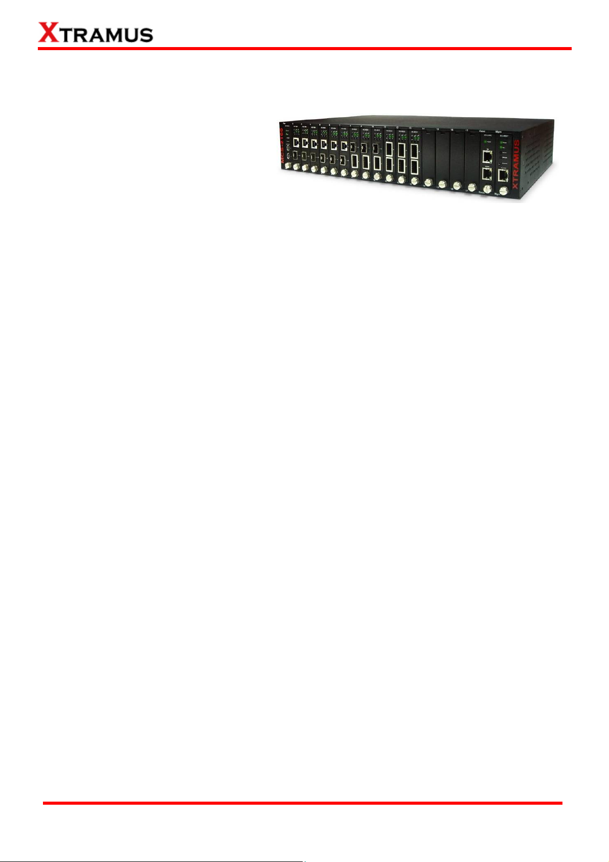
1.1. General Descriptions of MCS-2160
MCS-2160 media converter chassis is a
complete and versatile solution for the
applications such as FTTx, CWDM, and
carrier Ethernet. By the diversified speeds
of 1,000Mbps and 10G, Xtramus provides
different XC series module cards for
different applications and can be applied according to your ideal network topology.
Combined with XC series module cards, MCS-2160 media converter chassis provide various interfaces
such as UTP, SFP, SFP+ and XFP. All these interfaces are developed to support the protocols such as
100Base-Tx, 100Base-Fx, 1000Base-T, 1000Base-X, 10GBase-T, 10GBase-LR and 10GBase-SR, thus
making your network more complete and solid.
Also, XC series module cards support MIB Counter Report including counters such as Packet, Byte,
Broadcast packet, Pause Frame, Length: 64 Bytes, Length: 65~127 Bytes, Length: 128~255 Bytes,
Length: 256~511 Bytes, Length: 512~1023 Bytes, Length: 1024~1518 Bytes, Unicast packet, Multicast
packet, CRC Error, IP Checksum Error, Under size packet, and Over size packet.
All XC series module cards are equipped with real-time LEDs which display the status of each port, thus
allowing users to view network status easily.
MCS-2160 media converter chassis provides an easy-to-access Management Webpage, allowing users
to view system status, counters, upgrading firmware/FPGA and network statistics. Moreover, XC-CASC
module card allows you to cascade multiple MCS-2160 chassis for managing these chassis at the same
time.
With various interfaces, MCS-2160 provides different conversions between fibers and copper wires in
10G Ethernet.
XTRAMUS TECHNOLOGIES®
8
E-mail: sales@xtramus.com
Website: www.Xtramus.com
Page 9

1.2. Features, Key Advantages, and Main Applications of MCS-2160
Features
¾ Diversified interfaces including SFP, SFP+, UTP and XFP
¾ Supports 3R (Re-generation, Re-timing, Re-shaping) Performance
¾ Supports Jumbo Frame
¾ Supports D/D (Digital Detection) functioned optical transceivers and overload protection
¾ Supports easy-to-use Management Webpage that allows users to view system status, counters,
upgrading firmware/FPGA and network statistics
¾ Multiple MCS-2160 chassis can be cascaded for system management
¾ Replaceable power modules for AC & DC power
¾ Supports Link Loss Forwarding
¾ Optional Fan Tray (MCS-FANT-05) which can be placed under MCS-2160 chassis for ventilation
Key Advantages
¾ Fast connection with multi-function
¾ Provide reliable long-distance connection
¾ Port supported: SFP, SFP+, UTP and XFP
Main Applications
¾ Media converter for network backbone
¾ Connection between fiber to copper or fiber to fiber 10G Ethernet equipment
¾ Can be applied in Telecommunication room, R&D laboratory, Data center, and etc
¾ Providing additional network management options
¾ Can be applied in Telecommunication room, R&D laboratory, Data center, etc
XTRAMUS TECHNOLOGIES®
9
E-mail: sales@xtramus.com
Website: www.Xtramus.com
Page 10
1.3. MCS-2160 Functions Overview
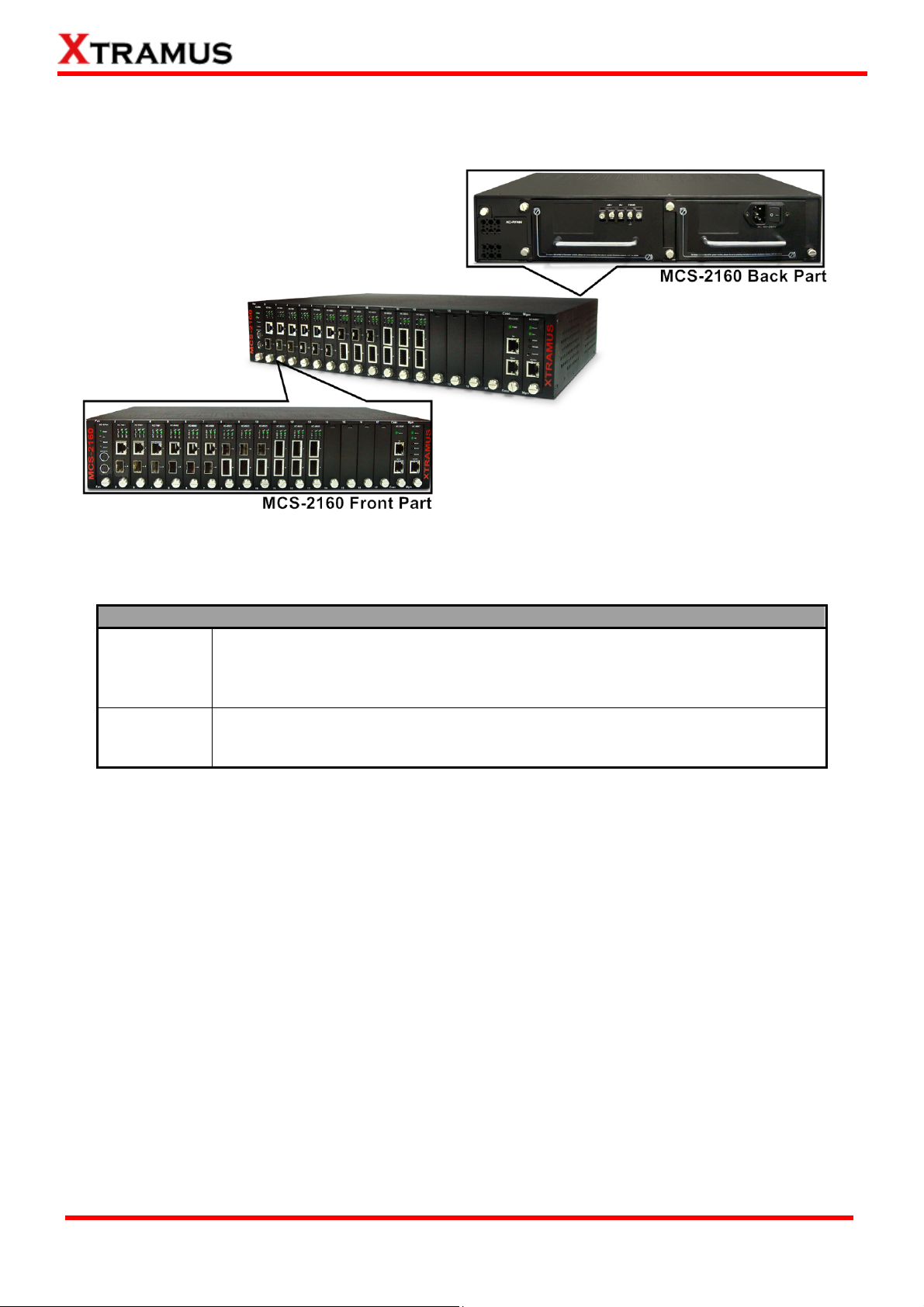
1.3.1. MCS-2160 Outer Case
MCS-2160’s outer case consists two parts: Front Part and Back Part. The figure above shows the outer
case of MCS-2160. Outer cases of other MCS-2160 are quite the same and can be related.
MCS-2160 Outer Case Overview
MCS-2160 has 16 slots for installation of module cards, where each module card
Front Part
provides media converting platforms for different types of media. Besides, the
Front Part includes 3 slots with Fan, CASC and Management module card
installed. Please see “1.3.2. MCS-2160 Front Part” for more detailed information.
MCS-2160’s back part includes 3 different slots for installation of a DC module,
Back Part
AC module and a Fan module. Please see “1.3.3. MCS-2160 Back Part” for
more detailed information.
.
XTRAMUS TECHNOLOGIES®
10
E-mail: sales@xtramus.com
Website: www.Xtramus.com
Page 11
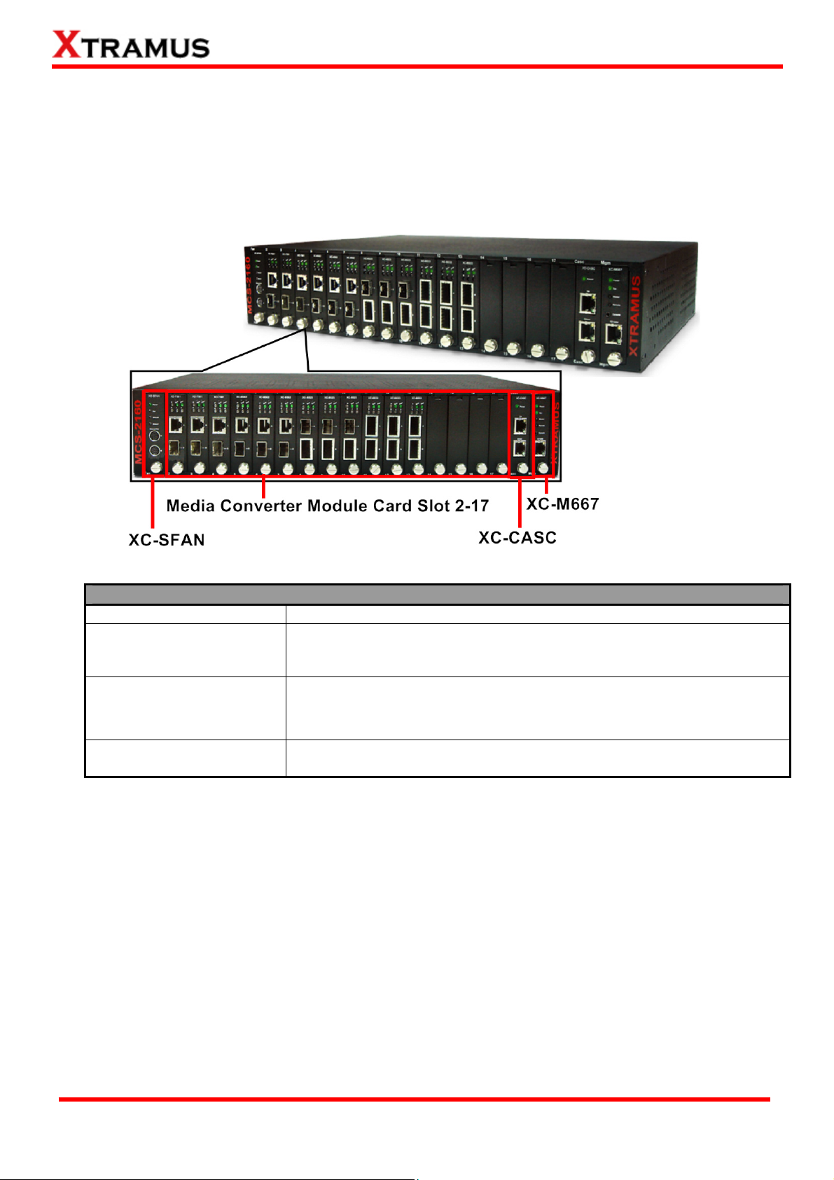
1.3.2. MCS-2160 Front Part
As mentioned in “1.3.1. MCS-2160 Outer Case”, MCS-2160 has 16 slots for installation of media
converter module cards and 3 slots comprising a Fan, CASC and Management module card installed.
Please see the sections down below for more detailed information/specification for MCS-2160 and the
module cards.
MCS-2160 Front Part
XC-SFAN
It is a fan module card pre-installed in front part of MCS-2160 chassis.
It is a module card pre-installed in MCS-2160 chassis with 1
XC-M667
Management port for accessing the Management Webpage and 1
Console port for accessing the HyperTerminal settings.
It is a module card pre-installed in MCS-2160 with 2 ports where each
XC-CASC
port can connect another MCS-2160 providing simultaneous access to
the Management Webpage.
Media Converter Module
Card Slots 2-17
*Note: XC-SFAN, XC-M667 and XC-CASC do not support hot swap, please, do not withdraw the XC-SFAN, XC-M667
and XC-CASC module card when the system is power on.
*Note2: Do not change XC-M667, XC-CASC and XC-SFAN inserting slot.
Media converter module cards can be inserted in each of slot 2-17.
XTRAMUS TECHNOLOGIES®
11
E-mail: sales@xtramus.com
Website: www.Xtramus.com
Page 12
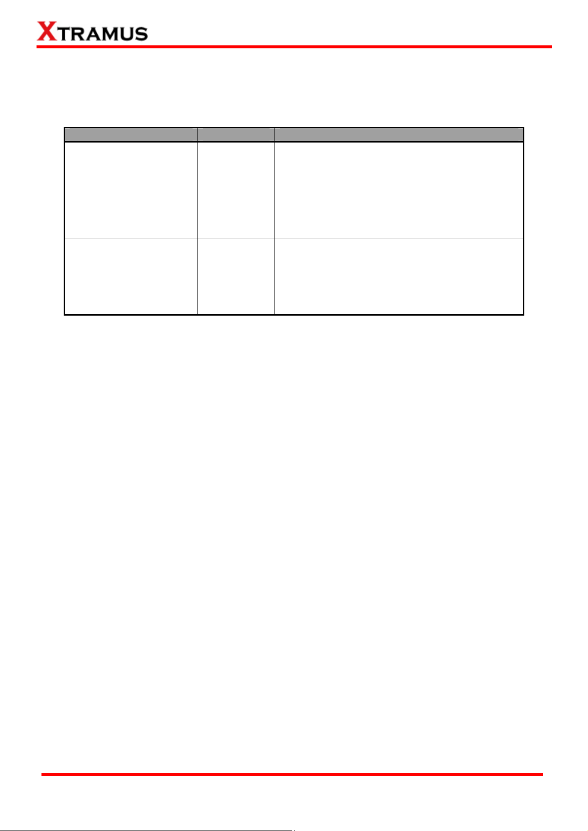
1.3.3. Module Cards
MCS-2160’s module cards can be divided into two categories: System Module Cards and Media
Converter Module Cards.
Module Card Type Module Card Description
These module cards can provide ventilation for
the MCS-2160 chassis, allowing users to view
counters/perform system maintenance, or
cascade multiple MCS-2160 chassis.
Please note that System Module Cards do not
System Module Cards
y XC-SFAN
y XC-M667
y XC-CASC
support hot-swap, and must be installed to their
designated slots on MCS-2160 chassis.
y XC-7S81
Media Converter
Module Cards
y XC-8S22
y XC-8S23
y XC-8S82
y XC-8S33
Module cards for media converting. These Media
Converter Cards can be installed in MCS-2160
Slot 2~17 and support hot-swap.
y XC-8S83
Please see the sections down below for more detail information regarding to MCS-2160 Module Cards.
XTRAMUS TECHNOLOGIES®
12
E-mail: sales@xtramus.com
Website: www.Xtramus.com
Page 13
1.3.3.1. System Module Cards
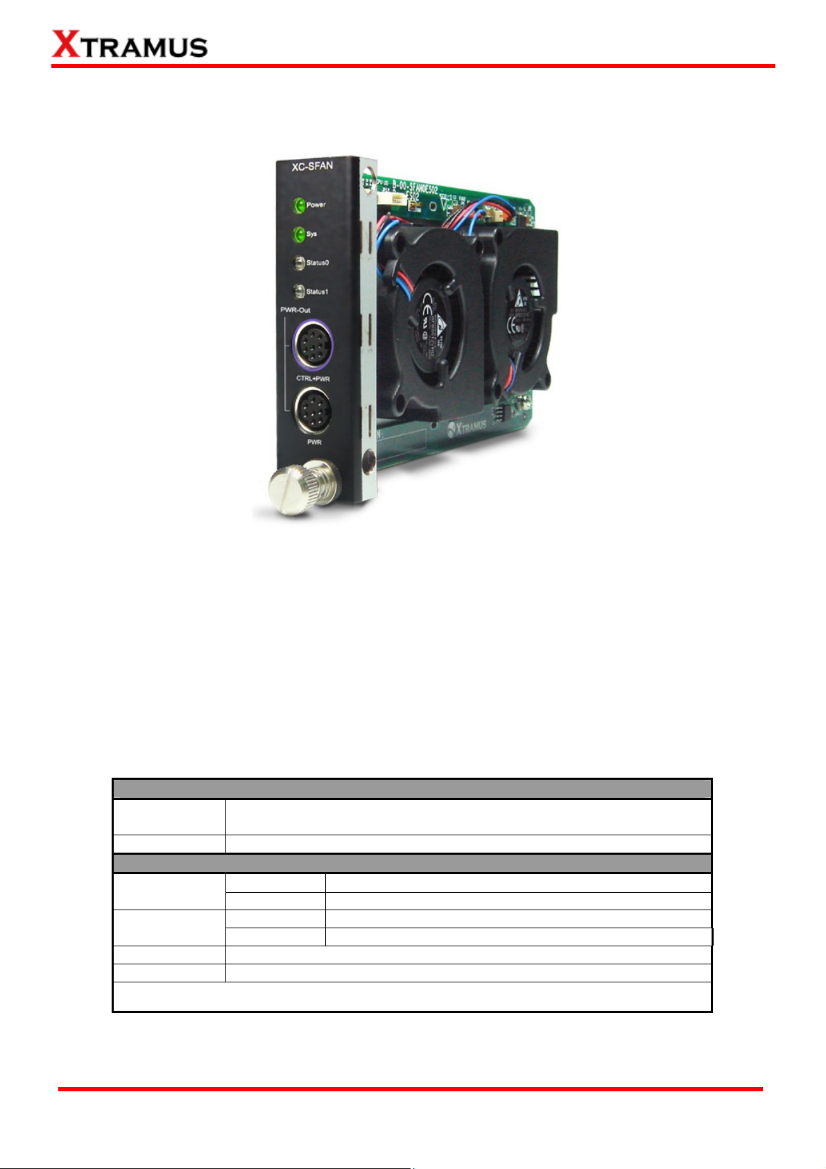
A. System Module Card – XC-SFAN
The XC-SFAN comes with your MCS-2160 chassis, and shall be installed on the Fan slot located on the
far left side of MCS-2160 chassis. This module card provides ventilation for the MCS-2160 chassis.
Also, XC-SFAN’s CTRL + PWR and PWR ports are designed to provide power source and gather
information for MCS-FANT fan tray. When connecting XC-SFAN to MCS-FANT fan tray, please do so by
connect to MCS-SFAN’s CTRL + PWR port to MCS-FANT’s CTRL + PWR port, and XC-SFAN’s PWR
port to MCS-FANT’s PWR port.
If you cross connect between CTRL + PWR port and PWR port of XC-SFAN and MCS-FANT, MCS-2160
will be seriously damaged.
Interface Ports
CTRL + PWR
PWR
LED
Power
Sys
Status 0
Status 1
*Note: XC-SFAN does not support hot-swap. Please do not draw the XC-SFAN module card from
MCS-2160 chassis when the system is power on.
8-Pin Mini-Din Port which can provide power for MCS-FANT and
system information regarding to MCS-FANT
8-Pin Mini-Din Port which can provide power for MCS-FANT
Green ON
Green OFF
Green ON
Green OFF
XC-SFAN is power on
XC-SFAN is power off
XC-SFAN is powering up properly
XC-SFAN is power off
User-defined LED
User-defined LED
XTRAMUS TECHNOLOGIES®
13
E-mail: sales@xtramus.com
Website: www.Xtramus.com
Page 14
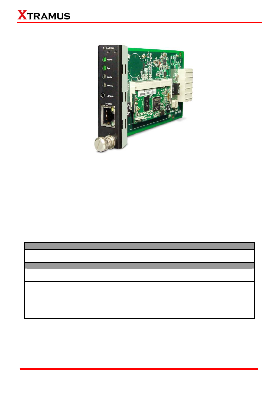
B. System Module Card – XM-M667
The XC-M667 comes with your MCS-2160 chassis, and shall be installed on the Mgm slot located on
the far right side of MCS-2160 chassis. This module card allows you to manage MCS-2160 chassis
via management webpage.
To access the Management Web Page of MCS-2160 for configuration on your browser, please
connect a RJ45 cable between the Management port of MCS-2160 and your PC.
To configure MCS-2160 on your PC (Telnet or Hyper Terminal), please connect a 2.5mm Phone Jack
to RS232 between your PC and Console Port of MCS-2160, where the 2.5mm Phone Jack end must
be plug in the Console Port of MCS-2160 and the RS232 end must be connect to your PC.
Interface Ports
Console Port
Management Port
One 2.5mm Phone Jack Port for managing MCS-2160 via HyperTerminal
One 10/100M RJ45 Port for managing MCS-2160 via management webpage
LED
Power
Green ON
Green OFF
Yellow ON
Sys
Green ON
(Blinking)
Green OFF
Master
Remote
*Note: XC-M667 does not support hot-swap. Please do not draw the XC-M667 module card from MCS-2160
chassis when the system is power on.
User defined LED
User defined LED
XC-M667 is power on
XC-M667is power off
XC-M667 is booting and preparing for test
XC-M667 is booting properly and is ready for test
XC-M667 is power off
XTRAMUS TECHNOLOGIES®
14
E-mail: sales@xtramus.com
Website: www.Xtramus.com
Page 15
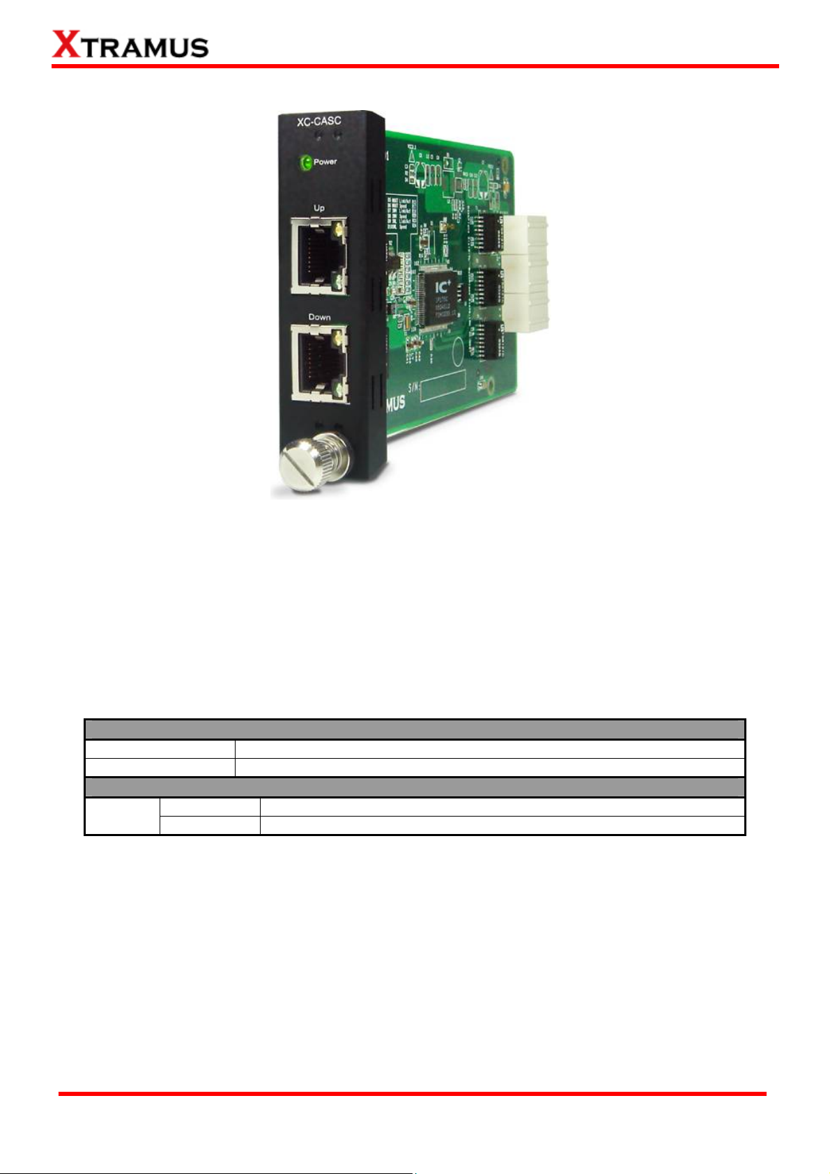
C. System Module Card – XC-CASC
The XC-CASC comes with your MCS-2160 chassis, and shall be installed on the Casc slot located on
the right side of MCS-2160 chassis (next to XC-M667 module card). This module card allows you to
cascade multiple MCS-2160 chassis.
On a rack mount structure with numerous MCS-2160 installed, you can inter-connect a MCS-2160
with another MCS-2160 situated above or below by using a RJ45 cable connecting theirs Port (Up) or
Port (Down). By doing the inter-connection, you can access the Management Web Page for all the
inter-connected MCS-2160 by only linking one of theirs XC-M667 Management Port on your PC.
Interface Ports
Port (Up)
Port (Down)
One 10/100M RJ45 Port for cascading another MCS-2160 chassis
One 10/100M RJ45 Port for cascading another MCS-2160 chassis
LED
Power
*Note: XC-CASC does not support hot-swap. Please do not draw the XC-CASC module card from MCS-2160
chassis when the system is power on.
Green ON
Green OFF
MCS-2160 is power on
MCS-2160 is power off
XTRAMUS TECHNOLOGIES®
15
E-mail: sales@xtramus.com
Website: www.Xtramus.com
Page 16
1.3.3.2. Media Converter Module Cards
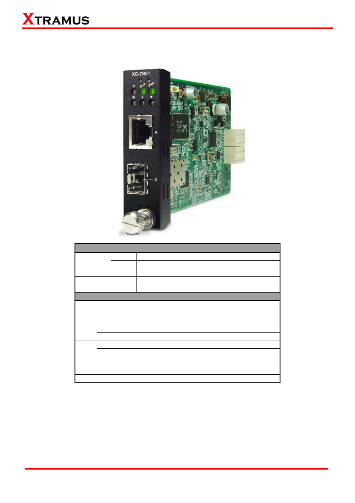
A. Media Converter Module Card – XC-7S81
XC-7S81 Front Panel Specification
Interface
Port A
Port B
Data Transfer Rate
Ethernet Mode
LED Status
Power
SYS
A/B
▇
▲
Green ON
Green OFF
Green ON
Yellow ON
Green ON
Green Blinking
Note: All LEDS will be off when upgrading FPGA/Firmware
XC-7S81 is power on.
XC-7S81 is power off.
XC-7S81 is booting properly and is ready for
tests.
Error occurred when booting XC-7S81.
Port A/B is connected.
Port A/B is transmitting/receiving data.
User-defined LED
User-defined LED
RJ45
SFP
1000 Mbps
1000Base-T
1000Base-X
XTRAMUS TECHNOLOGIES®
16
E-mail: sales@xtramus.com
Website: www.Xtramus.com
Page 17
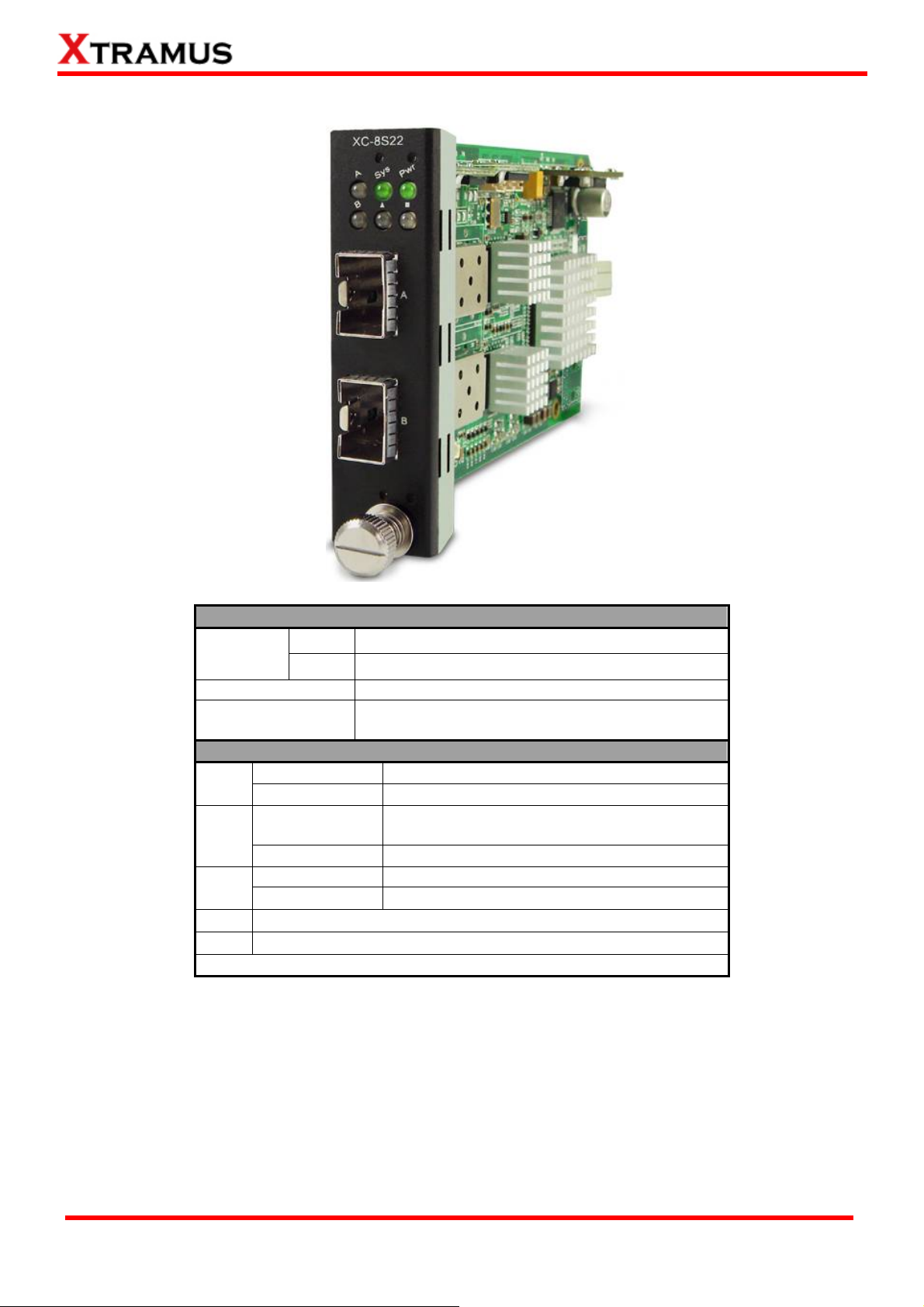
B. Media Converter Module Card – XC-8S22
XC-8S22 Front Panel Specification
Interface
Port A
Port B
Data Transfer Rate
Ethernet Mode
LED Status
Power
SYS
A/B
▇
▲
Green ON
Green OFF
Green ON
Yellow ON
Green ON
Green Blinking
Note: All LEDS will be off when upgrading FPGA/Firmware
XC-8S22 is power on.
XC-8S22 is power off.
XC-8S22 is booting properly and is ready for
tests.
Error occurred when booting XC-8S22.
Port A/B is connected.
Port A/B is transmitting/receiving data.
User-defined LED
User-defined LED
SFP+
SFP+
10Gbps
10GBase-LR
10GBase-SR
XTRAMUS TECHNOLOGIES®
17
E-mail: sales@xtramus.com
Website: www.Xtramus.com
Page 18
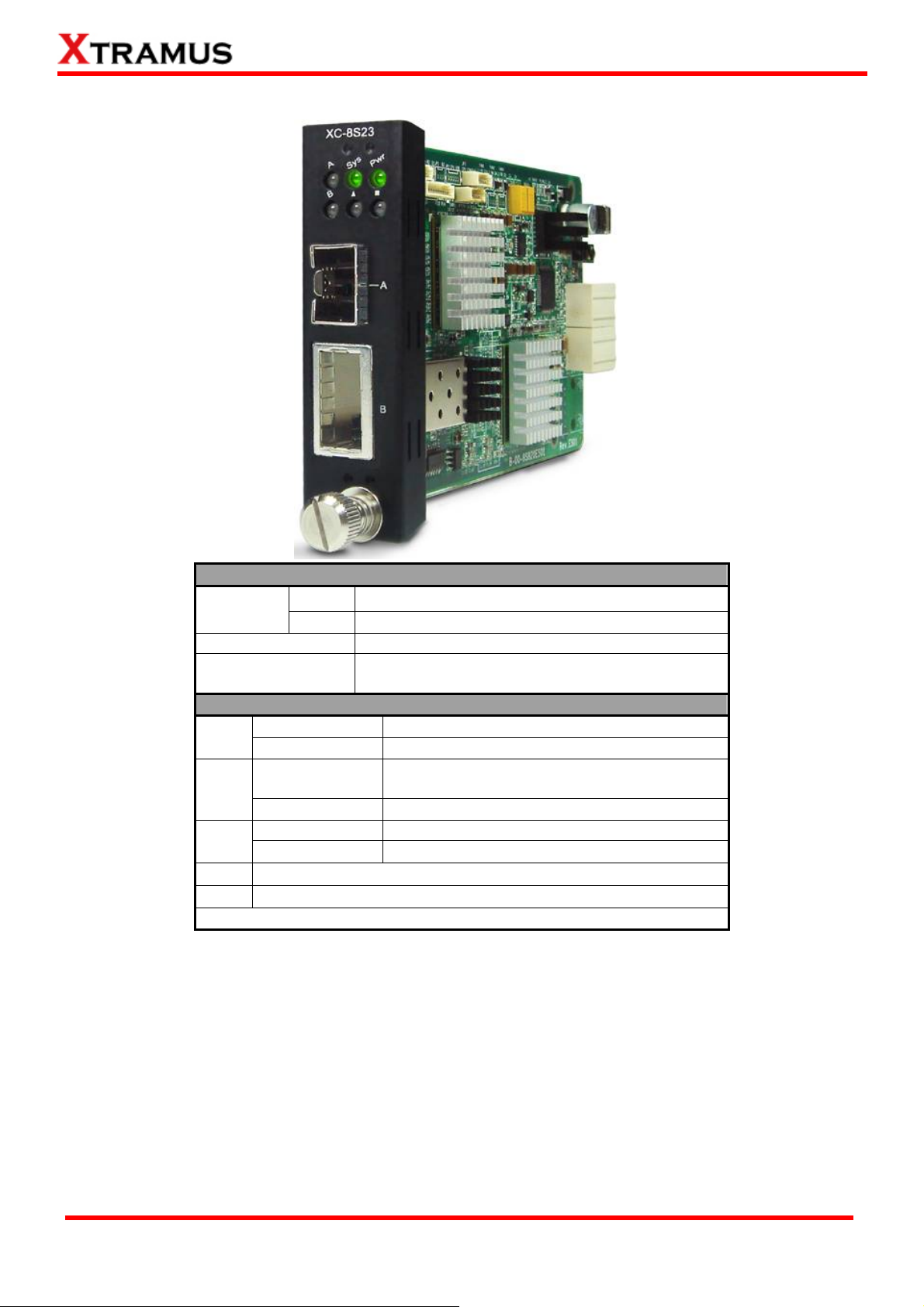
C. Media Converter Module Card – XC-8S23
XC-8S23 Front Panel Specification
Interface
Port A
Port B
Data Transfer Rate
Ethernet Mode
LED Status
Power
SYS
A/B
▇
▲
Green ON
Green OFF
Green ON
Yellow ON
Green ON
Green Blinking
Note: All LEDS will be off when upgrading FPGA/Firmware
XC-8S23 is power on.
XC-8S23 is power off.
XC-8S23 is booting properly and is ready for
tests.
Error occurred when booting XC-8S23.
Port A/B is connected.
Port A/B is transmitting/receiving data.
User-defined LED
User-defined LED
SFP+
XFP
10Gbps
10GBase-LR
10GBase-SR
XTRAMUS TECHNOLOGIES®
18
E-mail: sales@xtramus.com
Website: www.Xtramus.com
Page 19
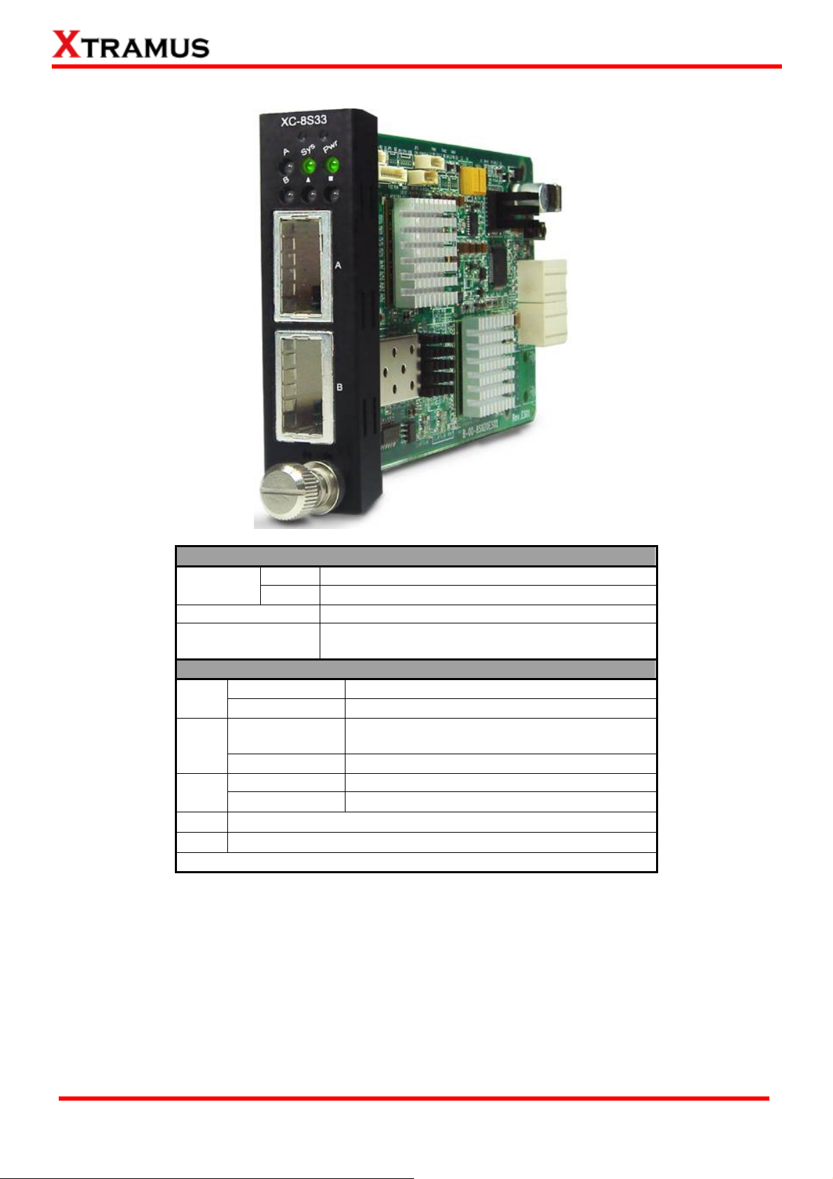
D. Media Converter Module Card – XC-8S33
XC-8S33 Front Panel Specification
Interface
Port A
Port B
Data Transfer Rate
Ethernet Mode
LED Status
Power
SYS
A/B
▇
▲
Green ON
Green OFF
Green ON
Yellow ON
Green ON
Green Blinking
Note: All LEDS will be off when upgrading FPGA/Firmware
XC-8S33 is power on.
XC-8S33 is power off.
XC-8S33 is booting properly and is ready for
tests.
Error occurred when booting XC-8S33.
Port A/B is connected.
Port A/B is transmitting/receiving data.
User-defined LED
User-defined LED
XFP
XFP
10Gbps
10GBase-LR
10GBase-SR
XTRAMUS TECHNOLOGIES®
19
E-mail: sales@xtramus.com
Website: www.Xtramus.com
Page 20
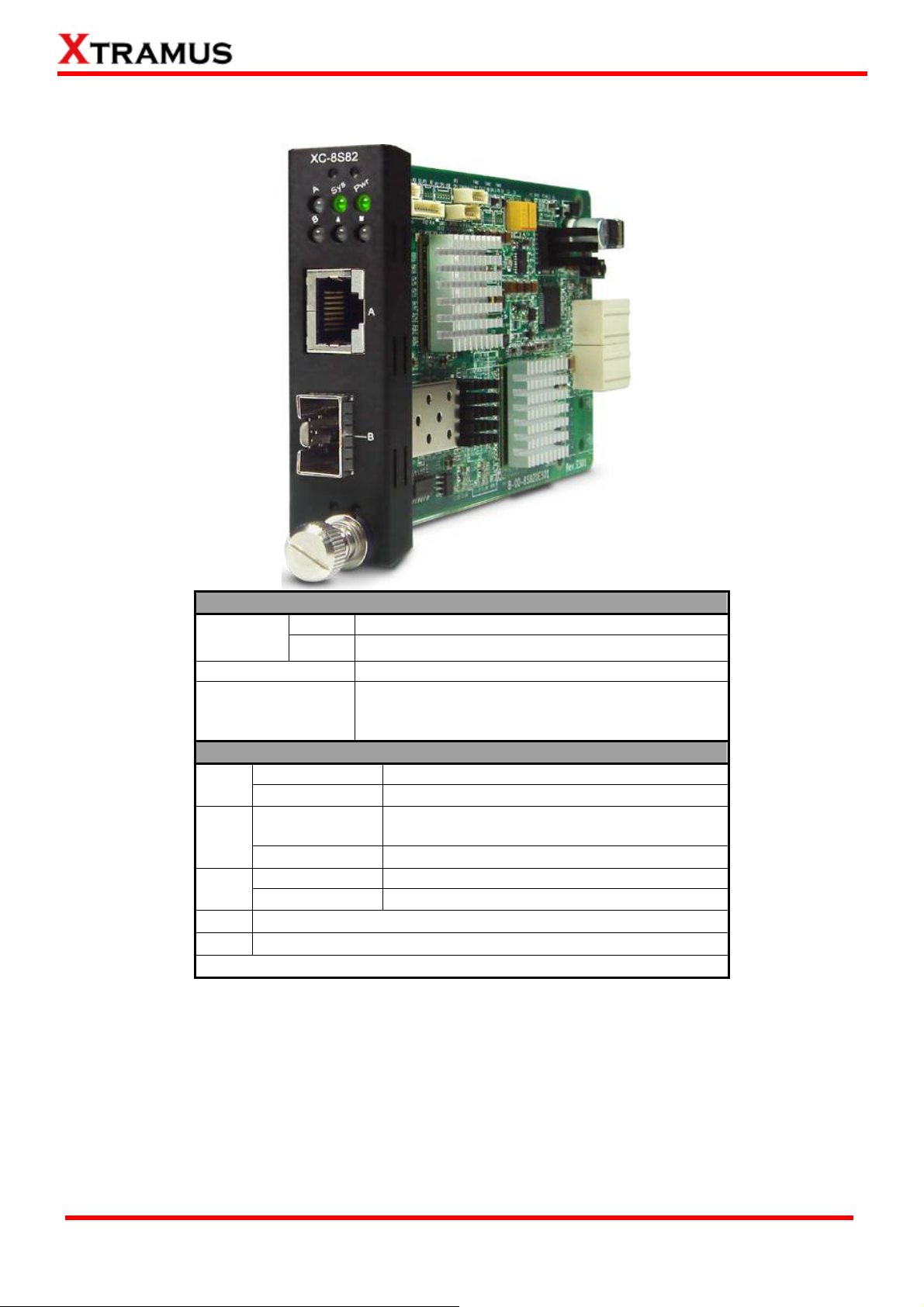
E. Media Converter Module Card – XC-8S82
XC-8S82 Front Panel Specification
Interface
Port A
Port B
Data Transfer Rate
Ethernet Mode
LED Status
Power
SYS
A/B
▇
▲
Green ON
Green OFF
Green ON
Yellow ON
Green ON
Green Blinking
Note: All LEDS will be off when upgrading FPGA/Firmware
XC-8S82 is power on.
XC-8S82 is power off.
XC-8S82 is booting properly and is ready for
tests.
Error occurred when booting XC-8S82.
Port A/B is connected.
Port A/B is transmitting/receiving data.
User-defined LED
User-defined LED
RJ45
SFP+
10Gbps
10GBase-LR
10GBase-SR
10GBase-T
XTRAMUS TECHNOLOGIES®
20
E-mail: sales@xtramus.com
Website: www.Xtramus.com
Page 21
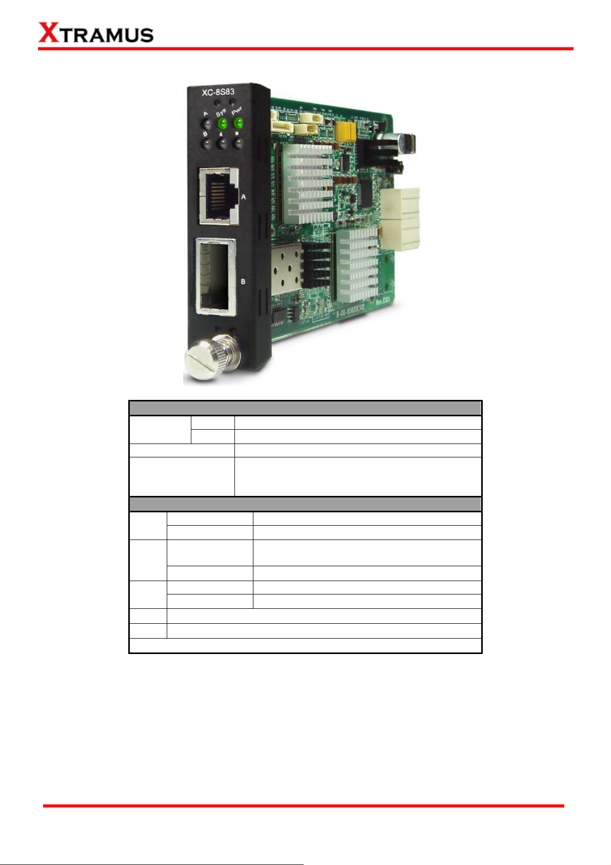
F. Media Converter Module Card – XC-8S83
XC-8S83 Front Panel Specification
Interface
Port A
Port B
Data Transfer Rate
Ethernet Mode
LED Status
Power
SYS
A/B
▇
▲
Green ON
Green OFF
Green ON
Yellow ON
Green ON
Green Blinking
Note: All LEDS will be off when upgrading FPGA/Firmware
XC-8S33 is power on.
XC-8S33 is power off.
XC-8S33 is booting properly and is ready for
tests.
Error occurred when booting XC-8S33.
Port A/B is connected.
Port A/B is transmitting/receiving data.
User-defined LED
User-defined LED
XFP
XFP
10Gbps
10GBase-LR
10GBase-SR
10G-Base-T
XTRAMUS TECHNOLOGIES®
21
E-mail: sales@xtramus.com
Website: www.Xtramus.com
Page 22
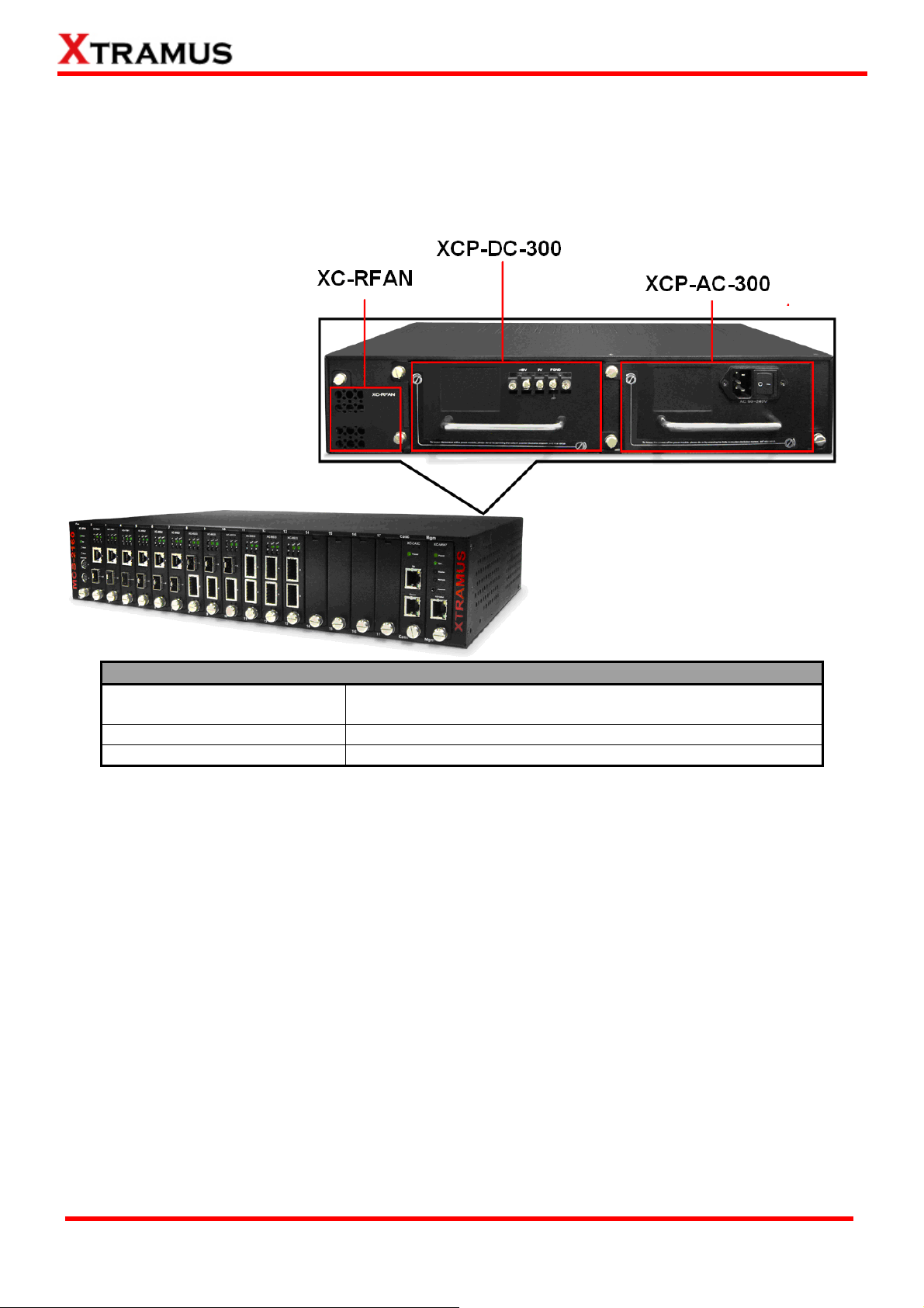
1.3.4. MCS-2160 Rear End
As mentioned in “1.3.1. MCS-2160 Outer Case”, MCS-2160’s rear end includes 3 different slots for
installation of a DC module, AC module and a Fan module. Please see the sections down below for
more detailed information/specification for MCS-2160 and modules.
MCS-2160 Back Part Description
XC-RFAN
XCP-DC-300
XCP-AC-300
It is a fan module card pre-installed in back part of MCS-2160
chassis.
It is a power module card based on DC power source.
It is a power module card based on AC power source.
XTRAMUS TECHNOLOGIES®
22
E-mail: sales@xtramus.com
Website: www.Xtramus.com
Page 23
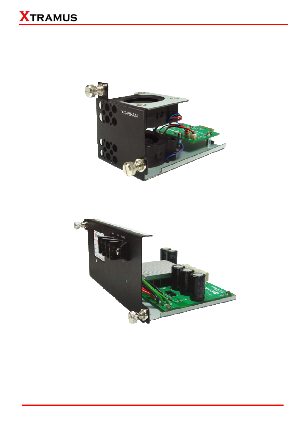
A. XC-RFAN Fan Module
The XC-RFAN consists of two fans as shown in the figure below. After installing XC-RFAN, the
Management Web Page will show the operation of XC-RFAN, please see the 3.1.4. MCS-2160
Management Webpage – Management for more information about showing the operation of
XC-RFAN.
B. XCP-DC-300
XCP-DC-300 is a power module providing power source of 300W DC Redundant SPS (Vin
36~72VDC).
The Power Jack of XCP-DC-300 is 3 Terminal Connectors: -48V, OV, FGND. The Terminal Connector
-48V and OV have a screw to fix an external power source cable. The FGND also has a screw, but
this screw should be fixed with an external cable connected to the ground.
XTRAMUS TECHNOLOGIES®
23
E-mail: sales@xtramus.com
Website: www.Xtramus.com
Page 24
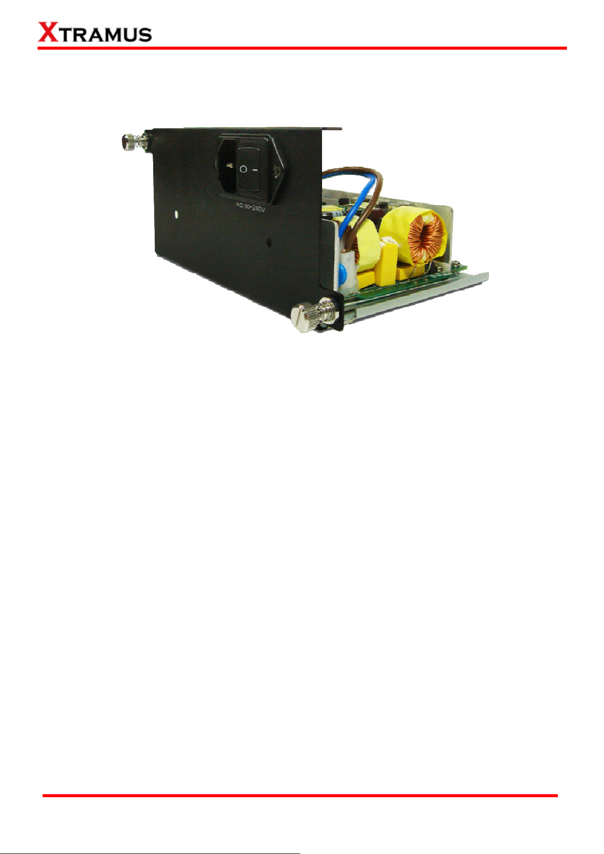
C. XCP-AC-300
XCP-AC-300 is a power module providing power source of 300W AC Redundant SPS (Vin
90~240VAC).
The Power Jack of XCP-AC-300 is Male IEC 320 Receptable. To activate XCP-AC-300 &
XCP-AC-100, just turn on/off the O/I button after connecting a power source cable in Male IEC 320
Receptable.
XTRAMUS TECHNOLOGIES®
24
E-mail: sales@xtramus.com
Website: www.Xtramus.com
Page 25
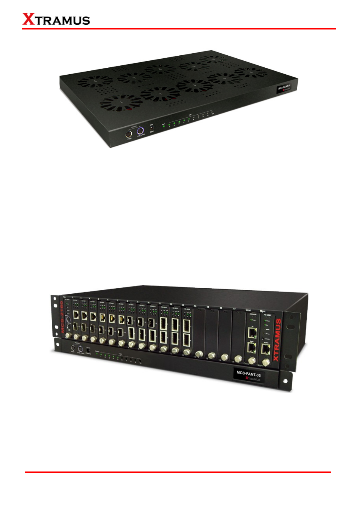
1.3.5. Optional Fan Tray – MCS-FANT-05
Set MCS-FANT-05 on the base of MCS-2160, with dimension of 441 mm x 310 mm x 29 mm.
XC-SFAN’s Port A and Port B are designed to provide power source and gather information for
MCS-FANT fan tray. When connecting XC-SFAN to MCS-FANT fan tray, please do so by connect to
MCS-SFAN’s CTRL + PWR port to MCS-FANT’s CTRL + PWR port, and XC-SFAN’s PWR port to
MCS-FANT’s PWR port.
If you cross connect between CTRL + PWR port and PWR port of XC-SFAN and MCS-FANT, MCS-2160
will be seriously damaged.
Also, please note that when placing MCS-2160 on top of MCS-FANT, MCS-2160’s four rubber feet must
be placed properly on the MCS-FANT’s four grooves, as shown in the figure down below:
To insure that MCS-FANT and MCS-2160’s ventilation fans can work properly, please leave adequate
space (10 cm at least) between the left/right sides and the buttom of MCS-FANT.
XTRAMUS TECHNOLOGIES®
25
E-mail: sales@xtramus.com
Website: www.Xtramus.com
Page 26

MCS-FANT contains LEDs that represent its ten fans. The figure down below shows how these fans are
numbered.
XTRAMUS TECHNOLOGIES®
26
E-mail: sales@xtramus.com
Website: www.Xtramus.com
Page 27

2. MCS-2160 Installation
MCS-2160 is a chassis with 16 slots for installation of media converter modules. Installing MCS-2160 is
very easy and simple: all you have to do is to plug the proper fiber/UTP cables into MCS-2160 ports like a
general Ethernet switch without any extra configurations. However, selecting the proper physical media
and applications in your network environment is crucial when installing MCS-2160. Besides, using the
proper method for installing media converter modules into MCS-2160’ slots is also crucial for the proper
functionality of MCS-2160. Please see the sections down below for detailed information regarding to
physical media types, MCS-2160 application and the proper method for installing a media converter
module.
2.1. Choices of UTP Cable and Optical fiber
2.1.1. 10GBASE-T (Copper Wire)
10GBASE-T, or IEEE 802.3an-2006, is a standard released in 2006 to provide 10 gigabit/second
connections over unshielded or shielded twisted pair cables and over distances up to 100 meters (330 ft).
10GBASE-T cable infrastructure can also be used for 1000BASE-T, allowing a gradual upgrade from
1000BASE-T, and auto-negotiation to select which speed to use.
10GBASE-T Connectors
10GBASE-T uses 650 MHz versions of the venerable IEC 60603-7 8P8C (RJ-45) connectors, which is
already widely used in Ethernet.
10GBASE-T Cables
10GBASE-T works up to 55 m (180 ft) with existing Category 6 cabling. In order to allow deployment at
the usual 100 m (330 ft), the standard uses a new partitioned Category 6a cable specification, designed
to reduce crosstalk between UTP cables.
The table down below is a reference regarding to UTP cable categories.
UTP Cable Categories References
Cat 5
Cat 5e
Cat 6
Provides performance of up to 100 MHz, and was frequently used on 100 Mbps Ethernet
networks. Cat 5 may not be suitable for 1000BASE-T gigabit Ethernet.
Provides performance of up to 100 MHz, and is frequently used for both 100 Mbps and
Gigabit Ethernet networks.
Provides performance of up to 250 MHz, more than double of category 5 and 5e. It works up
to 55 m (180 ft) for 10Gbps Ethernet.
Provides performance of up to 500 MHz. It is suitable for
10GBASE-T and works up to 100 m (330 ft) for 10Gbps
Cat 6a
Ethernet. All the cables mentioned above do not have
individually- shielded pairs as the picture here, including
Cat 6a.
This standard specifies four individually-shielded pairs (STP) inside an overall shield.
Cat 7
Designed for transmission at frequencies up to 600 MHz. It has better performance than Cat
6a.
XTRAMUS TECHNOLOGIES®
27
E-mail: sales@xtramus.com
Website: www.Xtramus.com
Page 28

2.1.2. 10GBASE-R (Optical Fiber)
10GBASE-R is 10Gbps Ethernet connection that based on IEEE802.3ae. It uses fiber as transmission
media with different specification of fiber, connector and transceiver. MCS-2160 uses two standards,
10GBASE-LR and 10GBASE-SR.
10GBASE-SR
10GBASE-SR ("Short Range") uses 64B/66B encoding and 850 nm wavelength lasers. It is designed to
support short distances over deployed multi-mode fiber cabling, it has a range of between 26 meters (85
ft) and 82 meters (270 ft) depending on cable type. It also supports 300 meters (980 ft) operation over
new, 50 µm 2000 MHz⋅km OM3 multi-mode fiber (MMF).
The transmitter can be implemented with a VCSEL (Vertical Cavity Surface Emitting Laser) which is low
cost and low power. MMF has the advantage of having lower cost connectors than SMF (single-mode
fiber) due to its wider core.
10GBASE-SR delivers the lowest cost, lowest power and smallest form factor optical modules.
10GBASE-LR
10GBASE-LR ("Long Range") is a Long Range Optical technology delivering serialized 10 gigabit
Ethernet over a laser with 1310 nm wavelength connection on single-mode fiber via IEEE 802.3 Clause
49 64B-66B Physical Coding Sub layer (PCS) using a line rate of 10.3125.
Single-mode optical cabling is used to interconnect transceivers at a distance spaced at 10 kilometers
(6.2 mi), but it can often reach distances of up to 25 kilometers (16 mi) with no data loss.
Fabry–Pérot lasers are commonly used in 10GBASE-LR optical modules. Fabry–Pérot lasers are more
expensive than VCSELs (mentioned above) but their high power and focused beam allow efficient
coupling into the small core of single mode fiber.
Fiber Specification
Fibers which support many propagation paths or transverse modes are called multi-mode fibers (MMF).
Fibers which can only support a single mode are called single-mode fibers (SMF). Multi-mode fibers
generally have a larger core diameter, and are used for short-distance communication links and for
applications where high power must be transmitted. Single-mode fibers are used for most
communication links longer than 200 meters.
Fiber Buffer/Jacket Color Meaning
Yellow Single-mode optical fiber, long distance connection
XTRAMUS TECHNOLOGIES®
Orange Multi-mode optical fiber, short distance connection
28
E-mail: sales@xtramus.com
Website: www.Xtramus.com
Page 29

Optical Fiber
As mentioned above, there are Single-mode and Multi-mode optical fiber. Both of them can be used for
XC media converter module series.
Fiber Connector
Optical fiber connector contains two ends of fibers and can attach
to SFP+ transceivers. There are two ports for one SFP+
transceiver: one fiber is for receiving and one fiber is for
transmitting. The picture here is called LC connector that can
attach to SFP+ transceiver.
Transceiver (Connector)
SFP+/XFP Transceivers can be plugged into XC media converter module’s
SFP+/XFP Ports. SFP+/XFP Transceivers are active components that
consume power from XC media converter module and are capable of
converting signals between optical data flow and electronic data flow.
For different transmission purpose, the component inside SFP+ form factor can
be 10BASE-LR or 10BAST-SR mode.
XTRAMUS TECHNOLOGIES®
29
E-mail: sales@xtramus.com
Website: www.Xtramus.com
Page 30

2.2. Hardware Installation
Please follow the steps shown below for a better understanding on how to install hardware in MCS-2160.
2.2.1. Bracket installation
Steps for installing a Bracket in MCS-2160
First of all, you must have an Empty
Slot for the Installation of a Bracket.
Attach the Bracket’s Latch on the
internal face of Chassis’ Latch.
XTRAMUS TECHNOLOGIES®
30
E-mail: sales@xtramus.com
Website: www.Xtramus.com
Page 31

Steps for installing a Bracket in MCS-2160
After attaching the Bracket’s Latch on
the internal face of Chassis’ Latch, let
this point be a fix central rotation point
and push the bottom part of Bracket
into MCS-2160.
Lock the Captive Screw into the
MCS-2160 to fix the Bracket into
MCS-2160.
XTRAMUS TECHNOLOGIES®
31
E-mail: sales@xtramus.com
Website: www.Xtramus.com
Page 32

2.2.2. Module Cards Installation
Steps for installing a Media Converter Module Card in MCS-2160
Aim the border side of a Media
converter Module Card with the
MCS-2160 internal slide road, and push
this Module Card into MCS-2160.
Please, make sure if the Media
Converter Module Card is well fixed into
MCS-2160 by pushing the bracket of
the Module Card into MCS-2160.
XTRAMUS TECHNOLOGIES®
32
E-mail: sales@xtramus.com
Website: www.Xtramus.com
Page 33

Steps for installing a Media Converter Module Card in MCS-2160
Lock the Captive Screw into the
MCS-2160 to fix the Module Card into
MCS-2160.
2.2.3. Power Module
2.2.3.1. XCP-DC-300
Steps for installing a XCP-DC-300
Installing a XCP-DC-300 into
MCS-2160 is quite simple. First of all,
attach the Power Module into the
respective slot of MCS-2160 and
push the handle of the Power Module
into the slot. After the Bracket of the
Power Module reaches the
MCS-2160, lock the captive screw
into MCS-2160 as shown by arrows 4
and 5.
Note: The XCP-DC-300 doesn’t
support hot swap. Please don’t
remove Power Module during
System operation.
XTRAMUS TECHNOLOGIES®
33
E-mail: sales@xtramus.com
Website: www.Xtramus.com
Page 34

2.2.3.2. XCP-AC-300
Steps for installing a XCP-AC-300
Installing a XCP-AC-300 into
MCS-2160 is quite simple. First of all,
attach the Power Module into the
respective slot of MCS-2160 and
push the handle of the Power Module
into the slot. After the Bracket of the
Power Module reaches the
MCS-2160, lock the captive screw
into MCS-2160 as shown by arrows 4
and 5.
Note: The XCP-AC-300 doesn’t
support hot swap. Please don’t
remove Power Module during
System operation.
2.2.4. Fan Module
2.2.4.1. XC-SFAN
Steps for installing the XC-SFAN
The XC-SFAN comes with your
MCS-2160 chassis, and shall be
installed on the Fan slot located on
the far left side of MCS-2160 chassis.
This module card provides ventilation
for the MCS-2160 chassis.
Also, XC-SFAN’s CTRL + PWR and
PWR ports are designed to provide
power source and gather information
for MCS-FANT fan tray. When
connecting XC-SFAN to MCS-FANT
fan tray, please do so by connect to
MCS-SFAN’s CTRL + PWR port to
MCS-FANT’s CTRL + PWR port, and
XC-SFAN’s PWR port to MCS-FANT’s
PWR port.
XTRAMUS TECHNOLOGIES®
34
If you cross connect between CTRL +
PWR port and PWR port of XC-SFAN
and MCS-FANT, MCS-2160 will be
seriously damaged.
E-mail: sales@xtramus.com
Website: www.Xtramus.com
Page 35

2.2.4.2. XC-RFAN
Steps for installing the XC-RFAN
Installing the XC-RFAN is quite simple,
just attach the XC-RFAN into the
respective slot of MCS-2160, and push
it into the slot. After the Bracket of the
XC-RFAN reaches the MCS-2160, lock
the captive screw into MCS-2160.
Note: The XC-RFAN doesn’t support
hot swap. Please don’t remove
Power Module during System
operation.
2.2.4.3. MCS-FANT-05
Steps for installing the MCS-FANT-05
Just set the
MCS-FANT-05 on the
base face of the
MCS-2160, and connect
the CTRL + PWR port and
PWR port of XC-SFAN
with the CTRL + PWR
port and PWR port of
XC-RFAN for power
supply.
Note: Cross-connection
between CTRL + PWR
and PWR ports will
seriously damage the
MCS-2160.
*Note: In a rack mount installation of MCS-2160, the distance between two MCS-2160 must unless be 2U (9 cm) for a better
efficiency of the MCS-FANT-05.
XTRAMUS TECHNOLOGIES®
35
E-mail: sales@xtramus.com
Website: www.Xtramus.com
Page 36

3. MCS-2160 Management
You can configure MCS-2160’s settings and view statistics generated while performing media converting
with MCS-2160 by connecting MCS-2160 and PC to the same network via an RJ45 cable, and accessing
MCS-2160’s settings/statistics with PC’s web browser.
Please see the sections down below for more information regarding to MCS-2160 management.
3.1. Managing MCS-2160 with Management Webpage
MCS-2160 is embedded with a management webpage, and can be accessed by connecting MCS-2160’s
Management Port to the network which your PC is connected to via an RJ45 cable.
Before accessing to MCS-2160’s configuration webpage with your PC’s web browser, please set the
network according MCS-2160’s default IP Address (192.168.1.8). The figure down below is an example of
network/PC settings for accessing MCS-2160 management webpage.
XTRAMUS TECHNOLOGIES®
36
E-mail: sales@xtramus.com
Website: www.Xtramus.com
Page 37

3.1.1. Accessing MCS-2160 Management Webpage
To access MCS-2160’s management webpage, please open your web browser, and
type in MCS-2160’s default IP address (192.168.1.8) in web browser’s URL field as
shown in the figure on the right side. If you’ve changed MCS-2160’s IP address, please input the IP
address you’ve changed to instead.
MCS-2160’ management webpage supports web browsers such as
Microsoft Internet Explorer
® (IE7 or above) and Firefox.
MCS-2160’s management webpage might not display correctly if you’re
using other web browser.
A window will pop up after you entering MCS-2160’s IP address. Please
enter the User Name and Password for MCS-2160’s configuration
webpage.
• Default User Name: admin
• Default Password: admin*
*Please note that the User Name and Password are case-sensitive.
For safety issues, it is highly recommended that you should change the User name and Password when
logging to MCS-2160’s management webpage for the first time.
After inputting MCS-2160 management webpage’s User Name and Password, you should be able to
see MCS-2160’s management webpage displayed on your web browser as shown in the figure down
below.
XTRAMUS TECHNOLOGIES®
37
E-mail: sales@xtramus.com
Website: www.Xtramus.com
Page 38

3.1.2. MCS-2160 Management Webpage – Overview
MCS-2160 Management Webpage Overview
The Setting Options contains options for MCS-2160 settings,
information, and statistics, which can be divided into:
• System: You can view system information here in this field.
• Management: This option allows you to make settings such as
MCS-2160’s IP address, SNMP, or user accounts.
A Setting Options
• Maintenance: This option allows you to save system settings,
reboot MCS-2160, and reset all MCS-2160’ settings to default
value.
• Language: You can set the Management Webpage language as
English, Chinese Simplified, Chinese Traditional, Japanese or
Korean.
B Model Name
C Main Display Screen
This field displays the model name of your MCS-2160.
The Main Display Screen displays the system information, network
tapping statistics, License Information, and Fans information.
XTRAMUS TECHNOLOGIES®
38
E-mail: sales@xtramus.com
Website: www.Xtramus.com
Page 39

3.1.3. MCS-2160 Management Webpage – System
3.1.3.1. System Information
System Information displays MCS-2160’ system information including:
System Information
S/N
MAC
Hardware version
Firmware Version
MCS-2160’ serial number.
MCS-2160’s MAC address.
Version of XC-M667’s PCB.
MCS-2160’s current firmware version.
IP Status
This field displays how MCS-2160 acquires its IP address.
• Static: MCS-2160’s IP, subnet mask, and gateway addresses are
IP Mode
assigned manually.
• DHCP: MCS-2160’s IP, subnet mask, and gateway addresses are
assigned automatically by a DHCP server.
IP Address
Subnet Mask
Gateway IP
MCS-2160’s IP address.
MCS-2160’s subnet mask.
MCS-2160’s gateway address.
License Information
This field displays the device type of your MCS-2160:
Hardware Type
Update Valid Date
• Normal: for users that purchased the License of MCS-2160.
• Evaluation: for users that are only testing the MCS-2160.
The time limit for using the MCS-2160.
Syslog Information
Syslog Server IP
This field displays the IP address for connection with 3CDaemon.
Fan Speed
Side Fan
Rear Fan
Shows the speed of Side Fan’s Fan1 and Fan2 in Rotation Per Minute (RPM).
Shows the speed of Rear Fan’s Fan1 and Fan2 in Rotation Per Minute (RPM).
XTRAMUS TECHNOLOGIES®
39
E-mail: sales@xtramus.com
Website: www.Xtramus.com
Page 40

3.1.3.2. Fan Tray Information
Fan Tray Information includes:
Fan Tray Information
Hardware Version
Firmware Version
Shows the Hardware version of your Fan Tray.
Shows the Firmware version of your Fan Tray.
Fan Speed
Fan1/Fan2/Fan3/Fan4/Fan5
The current speed of each Fan.
Update Fan Tray Firmware
Click the Browse… button to choose the Firmware update files, and click the Send button to start
updating your Fan Tray firmware.
*Note: The Fan Speed will auto-refresh during the operation of the MCS-2160.
XTRAMUS TECHNOLOGIES®
40
E-mail: sales@xtramus.com
Website: www.Xtramus.com
Page 41

3.1.4. MCS-2160 Management Webpage – Management
There are 11 options available for Management, which includes:
• IP Settings: Allows you to set how MCS-2160 will acquire its IP, subnet mask, and gateway
addresses. Also, you could input these addresses manually here.
• Syslog Settings: Shows the link status of each module on 3CDaemon.
• User Settings: Allows you to change MCS-2160’s configuration webpage Password.
• SNMP Settings: Sets the restriction for accessing the SNMP.
• Time Settings: Sets the date and time display of your MCS-2160.
• Mail Settings: Sets the basic info for sending warning e-mail to designated mail box.
• Safety Settings: Sets the temperature in degree centigrade for shutdown your MCS-2160.
• Configuration Settings: You can save and load your MCS-2160 configuration here.
• Media Converter Management: Sets the MCM-W series counter of same LAN to be displayed.
• Chassis Management: Displays the status of MCS-2160 and modules cards, also it allows you to
see the counter, to do the FPGA / Firmware upgrading, to power on/off module card and access
module card’s port settings.
• Chassis Overview: Displays the parameters of each slot of MCS-2160.
A. IP Configuration
IP Configuration
You can choose how MCS-2160 acquires its IP, subnet mask, and
gateway addresses. There are two modes available:
IP Mode
• Static: You have to input MCS-2160’s IP, subnet mask, and
gateway addresses manually in the fields down below.
• DHCP: MCS-2160 acquires its IP, subnet mask, and gateway
addresses automatically from network’s DHCP server.
IP Address
Subnet Mask
Gateway
Apply
*Note1: The default IP address for MCS-2160 is 192.168.1.8.
You can input MCS-2160’s IP address here in this field.
You can input MCS-2160’s subnet mask here in this field.
You can input MCS-2160’s gateway address here in this field.
Apply the changes you’ve made here.
XTRAMUS TECHNOLOGIES®
41
E-mail: sales@xtramus.com
Website: www.Xtramus.com
Page 42

B. Syslog Settings
Syslog Configuration
Syslog Receiver IP
Apply
You may set your Syslog Receiver IP in this field. The default
Syslog Receiver IP is 192.168.1.17 .
Apply the changes you’ve made here.
Before accessing Syslog Configuration for MCS-2160, please download and install the 3CDaemon
software. Please refer to the interface of 3CDaemon shown below:
3CDaemon
A
B
Please choose the Syslog Server option from the left side option of the
3CDaemon interface.
IP Address
This field shows the currently status of each module based on Time, IP
Address, Msg Type and Message. The status to be shown includes: system
C
turn on/off, hot swap, updating F/W, module link status, IP setting, syslog
setting, user setting, save changes, system reboot, update fan tray, usc
setting, clear counter.
XTRAMUS TECHNOLOGIES®
Time
Msg Type
Message
Shows the time record of each event.
The IP address of the source.
The type of information currently displayed.
The currently status of the connected module.
42
E-mail: sales@xtramus.com
Website: www.Xtramus.com
Page 43

On the Syslog Server option, choose the Configure Syslog Server to pop up 3CDaemon
Configuration window. In this 3CDaemon Configuration window, you may modify settings of:
Directory for syslog, Who can log to this and Log messages to.
Click the button of Stop/Start to enable or unable 3CDaemon to receive signals from your MCS-2160.
XTRAMUS TECHNOLOGIES®
43
E-mail: sales@xtramus.com
Website: www.Xtramus.com
Page 44

Click the Clear list option to delete all the records of Time/IP Address/Msg Type/Message of each
module shown in the right field.
Choose the View Log files to open the saved log file from your PC.
XTRAMUS TECHNOLOGIES®
44
E-mail: sales@xtramus.com
Website: www.Xtramus.com
Page 45

C. User Settings
For issues regarding to system security, MCS-2160 has 2 different user security levels, which are:
• Administrator: User with Administrator privilege can change MCS-2160 system settings and
view system information/statistics.
• Guest: User with Guest privilege can only view system information/statistics.
User Settings for Administrator/Guest
Input the password here in this field. Please note that the
New Password
password must contain at least 5 alphanumeric characters
and is case sensitive.
Confirm New Password
Apply
Please input the password here again for confirmation.
Apply the changes you’ve made here.
XTRAMUS TECHNOLOGIES®
45
E-mail: sales@xtramus.com
Website: www.Xtramus.com
Page 46

D. SNMP Settings
SNMP v1, v2 & v3 Settings
SNMP v1&v2
SNMP v3
Apply
Download MIB File
Enable
Read Community
Write Community
Enable
Security Name
Auth Password
Priv Password
Enable or disable SNMP v1&v2’s
function.
Set read for public or private use.
Set write for public or private use.
Enable or disable SNMP v3.
Set SNMP v3 username.
Set authorization password for accessing
SNMP v3.
Set private password for accessing
SNMP v3.
Apply the changes you’ve made here.
By clicking the Download button, you can save your SNMP
Settings on your PC or search on Internet for a program to run
the SNMP Settings.
XTRAMUS TECHNOLOGIES®
46
E-mail: sales@xtramus.com
Website: www.Xtramus.com
Page 47

E. Time Settings
System Time Setting
Get Computer Time
*Note: for Time and Date settings please install battery on your XC-M667 module card.
Get Device Time
Set Device Time
Save the settings made from Set Device Time.
Set your MCS-2160 date and time manually.
Set your MCS-2160 date and time as your current connected
computer time.
XTRAMUS TECHNOLOGIES®
47
E-mail: sales@xtramus.com
Website: www.Xtramus.com
Page 48

F. Mail Settings
Mail Configuration
Enable
POP3 Server Address
E-mail Box Account
E-mail Box Password
Sender’s E-mail
Address
Destination E-mail
Address
E-mail Sending
Interval(minute)
You can able or disable your MCS-2160 mail warning function.
Sets your POP3 server address.
Sets the e-mail account for your MCS-2160.
Sets the e-mail password for your MCS-2160.
Sets the e-mail address of the Sender of warning e-mail.
Sets the e-mail address of the Receiver of warning e-mail.
Sets the time interval for sending the e-mail.
Selects the content to be included on your warning e-mail. There
E-mail Sending Content
includes Port link state change warning, DDMI warning, Card
state change warning, Power supply change warning,
Temperature warning and Fan tray warning.
Apply
*Note: XC-7S81 module card doesn’t support the function “Temperature warning”.
Apply the changes you’ve made here.
XTRAMUS TECHNOLOGIES®
48
E-mail: sales@xtramus.com
Website: www.Xtramus.com
Page 49

G. Safety Settings
Safety Settings
Enable
Temperature
threshold
Apply
*Note: XC-7S81 module card doesn’t support the “Safety Configuration” function.
H. Configuration Settings
You can able or disable the Safety Configuration function.
Your MCS-2160 will shutdown when it reach the temperature (60, 65,
70, 75, 80) that you set here to avoid any damage to your MCS-2160
system.
Apply the changes you’ve made here.
Upload or Download Configuration
Upload Configuration
File
Download
Configuration File
You can choose the file to be uploaded by clicking the
Browse… button and than click the Upload button to process
the uploading.
You can save as your MCS-2160’s setting by clicking the
Download button.
XTRAMUS TECHNOLOGIES®
49
E-mail: sales@xtramus.com
Website: www.Xtramus.com
Page 50

I. Media Converter Management
Above shows the Media Converter Management option interface. You can set the Media Converter of
the same LAN of your MCS-2160 to be displayed by choosing Create new user button, and than
choose the Go button to apply your settings. For more details, please see the table below:
Media Converter Management Settings
Index
Status
Type
IP
SNMP Private/Public
Note
Create
Edit
Delete
Go
Counter
The order number of the selected Media Converter.
Shows the status of selected Media Converter.
Display the Media Converter type.
The IP address of the selected Media Converter.
The privacy status of SNMP of the selected Media Converter.
You may type notes on this field during Create new user.
Choosing this option allows you to create a new account of
Media Converter.
Choosing this option allows you to modify the settings of the
selected Media Converter made on Create option.
Choosing this option allows you to delete selected Media
Converter.
Apply the changes you’ve made here.
Show the Counter table of the selected Media Converter.
For the Media Converter of the same Network Segment as MCS-2160, the Media Converter will be
auto-detected and auto-created as a new user on the list of Media Converter Management.
XTRAMUS TECHNOLOGIES®
50
E-mail: sales@xtramus.com
Website: www.Xtramus.com
Page 51

If you click the Counter button as shown below, you will open the Counter screen of the Media
Converter showing the Network Port Statistics:
Please refer to the figure down below for the Counter screen of Media Converter:
Media Converter Counter
Scroll down this field to select others Media Converter that is connected to the same
A
LAN as your MCS-2160 to show theirs respective Counter.
Click the Clear button to clean the Network Port Statistics of the Media Converter’s
B
Counter.
XTRAMUS TECHNOLOGIES®
51
E-mail: sales@xtramus.com
Website: www.Xtramus.com
Page 52

J. Chassis Management
Choosing the Chassis Management option will pop up the Port State Overview screen as shown
above. In here, you will find the status of slot 2~17, XC-SFAN, XC-RFAN, Fan Tray, XCP-DC-300 &
XCP-DC-100 and XCP-AC-300 & XCP-AC-100. This interface will also display all the cascaded
MCS-2160 ID by order of Chassis 0, Chassis1, Chassis2 up to Chassis9.
Port State Overview
Display the Chassis ID.
A
Shows the status of each slot 2~17, from the top left to the top right is slot 2~9, and
B
from the bottom left to the bottom right is slot 10-17.
Shows the status of XCP-DC-300 & XCP-DC-100 and XCP-AC-300 & XCP-AC-100, if
the left one turns green, than indicates that the MCS-2160 is power on by
C
XCP-AC-300 or XCP-AC-100; if the right one turns green, than indicates that the
MCS-2160 is power on by XCP-DC-300 or XCP-DC-100.
Shows the status of XC-SFAN (Side FAN), XC-RFAN (Rear FAN) and MCS-FANT,
D
where FAN1, FAN2…FAN5 refers to the number marked on the physical MCS-FANT.
*Note : The system is able to cascade up to 10 MCS-2160.
XTRAMUS TECHNOLOGIES®
52
E-mail: sales@xtramus.com
Website: www.Xtramus.com
Page 53
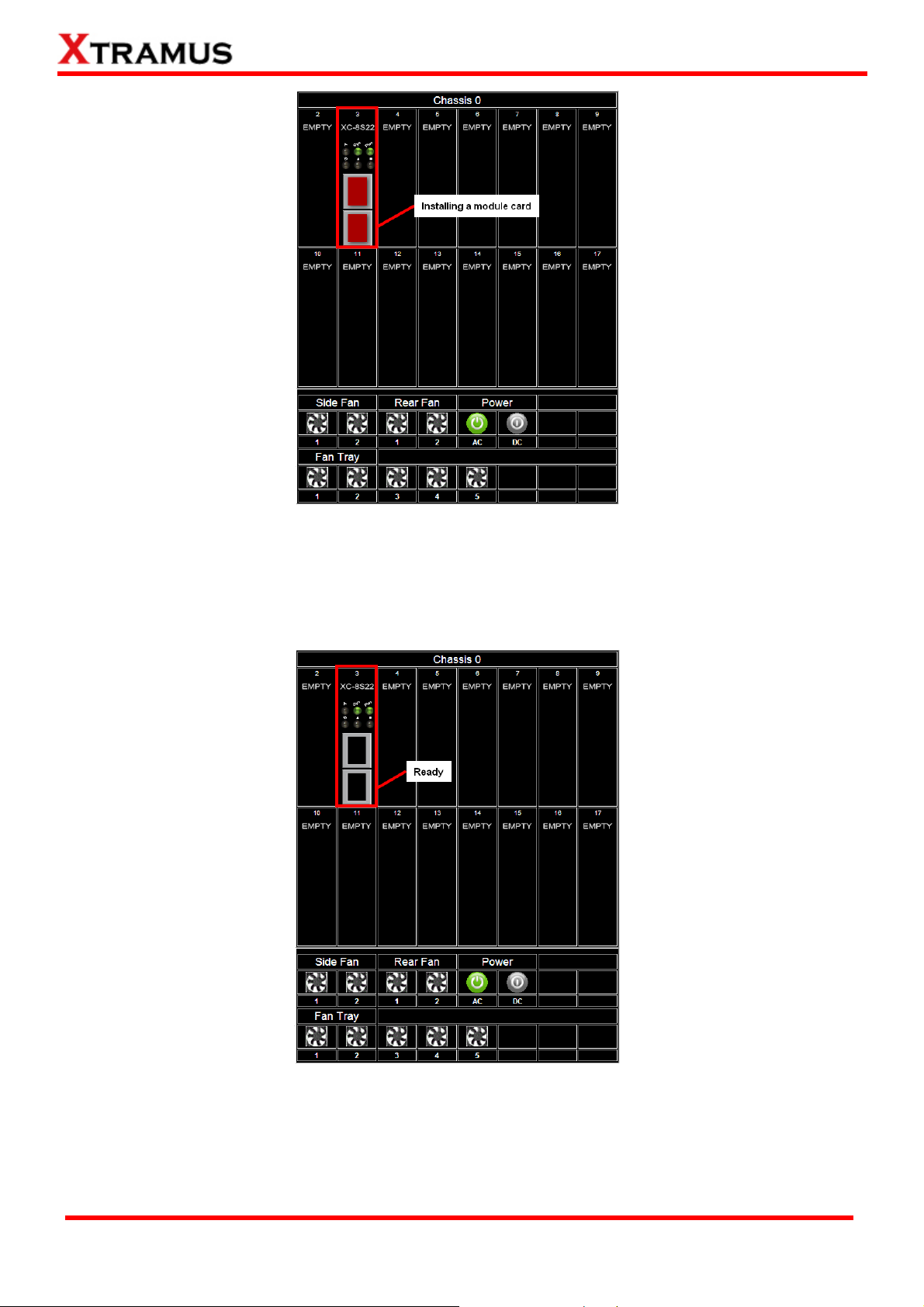
After installing a module card in one of the slot 2-17, it will modify the inserted slot as shown above.
Initially, the port of the slot will show in red color which indicates that the module card is initiating the
connection with chassis. The slot will turn black when the module card completes the connection with
chassis.
After few seconds of the installation of the module card, the Sys / Pwr LED will turn green, and the
port of the module card will turn in black, this indicates respectively that the module card is ready for
use and the port is available for connecting a cable.
XTRAMUS TECHNOLOGIES®
53
E-mail: sales@xtramus.com
Website: www.Xtramus.com
Page 54

Click the slot with the module card installed to show a table of options as shown above.
Module Card Options
Information
Port A/B DDMI
Counter
Upgrade
Power Control
Port A/B USC Setting
Port A/B USC
Note: The XC-8SXX series don’t support Port Configuration function.
XTRAMUS TECHNOLOGIES®
Shows the Module Card information
Shows the DDMI’s parameters of PortA/B
Shows the Port Counter Statics
Allows you to update the Firmware and FPGA
Allows you to turn on / off the Module Card
Allows you to turn on / off and setting the Port A/B USC
Allows you to see/ refresh/ clean the Port A/B USC table
54
E-mail: sales@xtramus.com
Website: www.Xtramus.com
Page 55

a. Information
Click the Information option to pop up the Card Information / License Information window as
shown above.
Card Information
S/N
MAC Address
H/W Version
FPGA Version
Firmware Version
Temperature
Port A/B Factory
Port A/B Wavelength
*Note: The Temperature may auto-refresh during the operation of the MCS-2160. The Port A/B Factory
and Wavelength will auto-refresh if you change the optical transceiver of your Port A/B.
Serial Number of Module Card
MAC Address of Module Card
Version of Module Card’s PCB
Version of FPGA
Version Firmware
The current Module Card’s temperature
You can view the manufacturer of your transceiver inserted in the
media converter module cards.
You can view the wave length of your transceiver inserted in the
media converter module cards.
License Information
This field displays the device type of your MCS-2160:
Hardware Type
Demo Time Left
• Normal: for users that purchased the License of
MCS-2160.
• Evaluation: for users that are only testing the MCS-2160.
The time limit for using the MCS-2160.
XTRAMUS TECHNOLOGIES®
55
E-mail: sales@xtramus.com
Website: www.Xtramus.com
Page 56

b. Port A/B DDMI
Click the Port A/B DDMI option to access the interface showing the parameters of DDMI for Port
A/B.
Port A/B Digital Diagnostics Monitoring Interface
Temperature (oC)
Supply Voltage (mV)
Tx Bias Current (mA)
Tx Power (dBm)
Rx Power (dBm)
*Note: The DDMI’s parameter will auto-refresh during the operation of MCS-2160.
Shows the Current temperature of the module card, and the
Maximum, Minimum and Warning Maximum temperature
supported.
Shows the Current voltage supplied in mV, and the Maximum,
Minimum and Warning Maximum acceptable voltage.
Shows the current Tx Bias Current in mA.
Shows the Current Tx Power in mW, and the Maximum, Minimum
and Warning Maximum Tx Power supported.
Shows the Current Rx Power in mW, and the Maximum, Minimum
and Warning Maximum Rx Power supported.
XTRAMUS TECHNOLOGIES®
56
E-mail: sales@xtramus.com
Website: www.Xtramus.com
Page 57
c. Counter
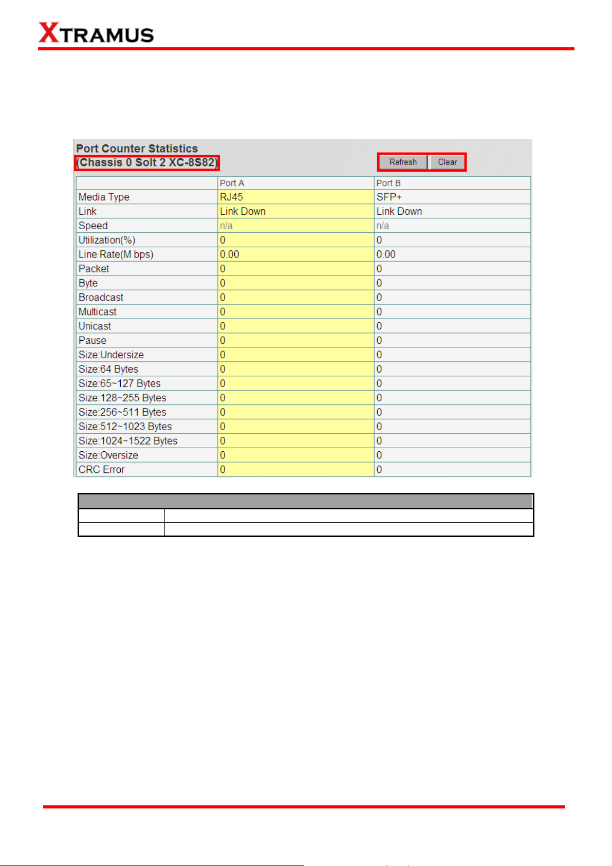
Click the Counter to pop up the Port Counter Statistics window as shown above. The Port
Counter Statistics can display statistics reports of MCS-2160’s Port A/B.
Port Counter Statistics
Refresh
Clear
Note: The Counter will also show the Chassis order and the order of the slot with the current module
card. For instance, the figure above shows Chassis 0 Card 3.
Refresh the configuration webpage and update the latest statistics.
Clear all statistics displayed in the table.
XTRAMUS TECHNOLOGIES®
57
E-mail: sales@xtramus.com
Website: www.Xtramus.com
Page 58

d. Upgrade
Click the Upgrade option to pop up the window for Update Firmware and Update FPGA as
shown above.
Update F/W (Firmware)
Browse…
Send
Click the Browse… button to choose the firmware file you would like to
upgrade. MCS-2160’s firmware files are in the format of “*.bin”.
Click this button to start upgrading MCS-2160’s firmware.
Update FPGA
Browse…
Send
Click the Browse… button to choose the FPGA file you would like to
upgrade. MCS-2160’s FPGA files are in the format of “*.bin”.
Click this button to start upgrading MCS-2160’s FPGA.
When updating the Firmware or FPGA, a progress bar will be displayed as shown below:
When finished updating the Firmware or FPGA, a warning window will pop up as shown below:
XTRAMUS TECHNOLOGIES®
58
E-mail: sales@xtramus.com
Website: www.Xtramus.com
Page 59

e. Power Control
Click the Power Control option to pop up the Power Control window as shown below.
Power Control
Power Off
Power On
Turns off the Module Card
Turns on the Module Card
f. Port A/B USC Setting
Click the Port A/B USC Setting option to pop up the Port A/B USC Setting window as shown
above.
Port A/B USC Setting
USC ON/OFF
USC Type
USC Value
Apply
Turns on/off the USC function.
The types of USC includes: DA, SA, VID, MPLS, DIP, SIP, DPort, Sport.
Allows you to input USC number.
Apply the changes you’ve made here.
XTRAMUS TECHNOLOGIES®
59
E-mail: sales@xtramus.com
Website: www.Xtramus.com
Page 60

g. Port A/B Universal Stream Counter
Click the Port A/B USC option to pop up Port A/B Universal Stream Counter window as shown
below.
Port A/B Universal Stream Counter
Refresh
Clear
*Note: The results of each parameters will auto-refresh during the operation of MCS-2160.
Refresh the Counter and update the latest statistics.
Clear all statistics displayed in the table.
h. Link Loss Forwarding (LLF)
Clicking the Link Loss Forwarding option will pop up the interface shown below, if you select Enable,
you will enable the Link Loss Forwarding function of your MCS-2160.
XTRAMUS TECHNOLOGIES®
60
E-mail: sales@xtramus.com
Website: www.Xtramus.com
Page 61

i. Module Card Options_XC-7S81
For XC-7S81 module card management function, it includes Port Configuration function.
The XC-7S81 module card management doesn’t include the Port A /B USC Setting and Port A/B
USC function.
XTRAMUS TECHNOLOGIES®
61
E-mail: sales@xtramus.com
Website: www.Xtramus.com
Page 62

Clicking the Port Configuration button will pop up the interface shown below:
Port Configuration_XC-7S81
Auto
Negotiation
Media
Type
Setting
Force
10/100/1000M,
10G
Off
Flow
On
Control
Setting
Apply
Off
Clicking on Apply of Media Type Setting and Flow Control Setting to respectively
save each configuration.
Select this option to let the system to decide the Media Type.
The availability of the media speed will depend on the capacity
of each module card. Selecting this option, will force the system
to run under the indicated velocity.
This option will lead the module card connection to link down
status.
Turn On the Flow Control function.
Turn Off the Flow Control function.
XTRAMUS TECHNOLOGIES®
62
E-mail: sales@xtramus.com
Website: www.Xtramus.com
Page 63

K. Chassis Overview
The Chassis Overview will display the parameters of all the MCS-2160’ slots, please refer to the figure
above. If you click the refresh button, you can refresh all the parameters.
All the cascaded MCS-2160’ slots will be displayed on the same interface, in which each MCS-2160
will be named in order of Chassis 0, Chassis 1, …, Chassis 9.
XTRAMUS TECHNOLOGIES®
63
E-mail: sales@xtramus.com
Website: www.Xtramus.com
Page 64

3.1.5. MCS-2160 Management Webpage – Maintenance
Four options are available in the Maintenance configuration webpage: Save Changes, Update F/W,
System Reboot, and Factory Defaults.
A. Save Changes
Save Changes
If you don’t save the setting you’ve made via MCS-2160’s configuration
Save
webpage, all settings will be erased after rebooting MCS-2160. Please click the
“Save” button to save the settings to MCS-2160’s NV-RAM.
B. Update F/W (Firmware)
Update F/W (Firmware)
Browse…
Send
*Note: For updating your MCS-2160, please update first all the MGM_RTC_v1.1b002 version, and than update to the
MGM_RTC_v1.1b003 or newest.
Click the Browse… button to choose the firmware file you would like to
upgrade. MCS-2160’s firmware files are in the format of “*.bin”.
Click this button to start upgrading MCS-2160’s firmware.
XTRAMUS TECHNOLOGIES®
64
E-mail: sales@xtramus.com
Website: www.Xtramus.com
Page 65
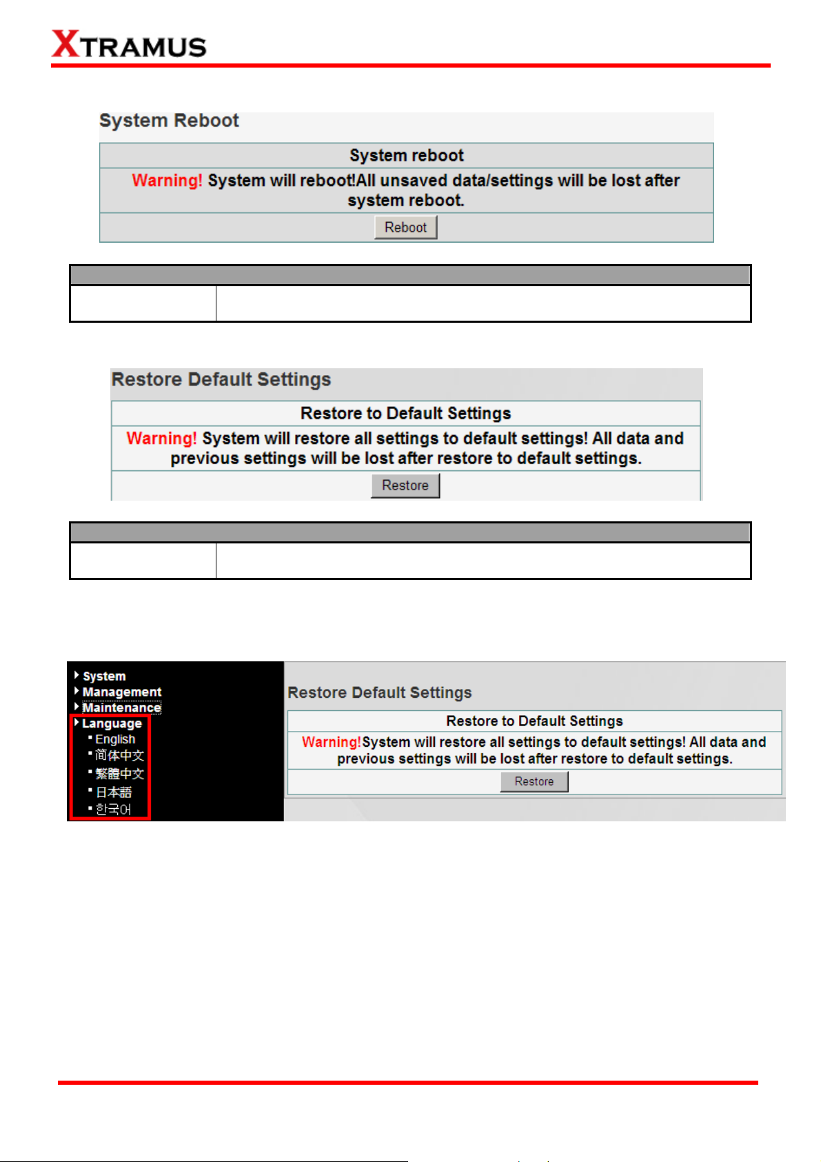
C. System Reboot
System Reboot
Reboot
D. Factory Defaults
You can reboot MCS-2160 by clicking the “Reboot” button. Please note that all
unsaved settings will be lost after system reboot.
Factory Defaults
Restore
You can set all MCS-2160’s settings to the default value by clicking the
“Restore” button.
3.1.6. MCS-2160 Management Webpage – Language
Three languages version are available for you to choose: English, Simplified Chinese, Traditional
Chinese, Japanese and Korean.
XTRAMUS TECHNOLOGIES®
65
E-mail: sales@xtramus.com
Website: www.Xtramus.com
Page 66

3.2. Managing MCS-2160 with HyperTerminal
MCS-2160 allows users to make system configurations and view test statistics/system information with
HyperTerminal. To access MCS-2160 via HyperTerminal, you have to connect XC-M667’s Console
Port with PC’s RS-232 Port via a 2.5mm Phone Jack to RS-232 cable as shown in the figure above.
Please Note: If you log in the Hyper Terminal to access the MCS-2160 system, the previous accessed
Web Management or Telnet will automatically log out from the MCS-2160 system.
XTRAMUS TECHNOLOGIES®
66
E-mail: sales@xtramus.com
Website: www.Xtramus.com
Page 67

3.2.1. HyperTerminal Settings for MCS-2160
After connecting the PC’s serial port to XC-M667’s Console Port via a 2.5mm Phone Jack to RS-232
cable, please start the HyperTerminal software installed on your PC and establish connection
according to the steps listed down below.
Establishing Connection with MCS-2160
1. Input a name for this connection, such as MCS-2160, and also select an icon for this connection.
Click “OK” to continue.
2. Select the COM port of PC for this connection. Click “OK” to continue.
3. Set the COM port parameters according to the settings listed
down below:
• Bits per second: 38400
• Data bits: 8
• Parity: None
• Stop bits: 1
• Flow control: None
Click “OK” to continue.
Click the “Enter” key on your keyboard to start setting MCS-2160 via HyperTerminal. To log in, please
type MCS-2160’s user name and password:
• Default User Name: admin
• Default Password: admin (Both the User Name and Password are case-sensitive.)
If you change MCS-2160’s user name and password with MCS-2160’s configuration webpage, please
log in with the new user name and password here.
3.2.2. MCS-2160 HyperTerminal Commands
After logging in MCS-2160 via HyperTerminal, a MCS-2160 Command Menu will be displayed, showing
MCS-2160’s HyperTerminal commands. Please see the table down below for brief descriptions of
MCS-2160 commands:
Command Alias Command Description
system sys
Ip ip
Cls cls
The system command allows you to view MCS-2160’s system information, make
system configurations, and upgrade MCS-2160’s firmware/FPGA.
The ip command allows you to view MCS-2160’s current IP settings or configure
these settings.
The cls command allows you to clear HyperTerminal screen.
The logout command allows you to log out. For security issues, it is
Logout logout
recommended that you should log out if you’re not using the HyperTerminal
anymore.
Please see sections down below for more detailed information regarding to MCS-2160’s command.
XTRAMUS TECHNOLOGIES®
67
E-mail: sales@xtramus.com
Website: www.Xtramus.com
Page 68

A. MCS-2160 HyperTerminal Command – system
Command Descriptions – system
The system show chassis command allows you to view
chassis
show
information
fant
show
MCS-2160’s Fan Tray status, PCB/firmware/FPGA versions, as well
as hardware temperature and Counter of each module card.
The system show information command display the S/N, MAC, PCB
version and Firmware version of your MCS-2160.
Shows the detail information of your connected MCS-FANT.
The system user show command allows you to view the current
users and their passwords.
The system user admin [name | password] <name | password>
command allows you to change the user name and its password of
Admin
User
the user with administrator privilege. For example, if you type in
system user admin name test123 and press enter, a user named
test123 with administrator privilege will be created.
The system user guest [name | password] <name | password>
command allows you to change the user name and its password of
Guest
the user with guest privilege. For example, if you type in system user
guest name test123 and press enter, a user named test123 with
guest privilege will be created.
Save
Logip
system
safety
The system save command allows you to save the current settings to MCS-2160’s
NV-RAM. Please note that all unsaved settings will be lost after system reboot.
Show
Set
show
enable
disable
value
This command will show your current Syslog Receiver IP.
You can set your Syslog Receiver IP by typing command: sys logip
set xxx.xxx.xxx.xxx .
This command will show you the status of this function and the set
temperature threshold.
This command will enable the safety function.
This command will disable the safety function.
This command allows you to set the temperature threshold. You can
set as 60, 65, 70, 75 and 80 degrees centigrades.
The system update [firmware/fant] [remote file] [host ip]
commands allow you to upgrade MCS-2160’s firmware/fant. The
following descriptions are for upgrading MCS-2160’s firmware.
However, procedures for upgrading MCS-2160’s fant are quite the
same and can be related.
1. Please download and install first the Tftpd32 software from
Update firmware/fant
internet.
2. Let the BIN file (firmware update file) inside a folder of your PC,
and open this file by open the folder with Tftpd32.
3. Set the Server Interface of Tftpd32 as 192.168.1.17.
4. On the Hyper Terminal screen, type in “sys update
[firmware/fant] [remote file] [host ip]” and click enter. Press Y
to proceed and start upgrading firmware, or press N to cancel.
5. MCS-2160 will reboot when finishing upgrading the firmware.
Reset
Reboot
*Note1: Please access the “Counter” by entering “sys show chassis”. Entering “0” to access the MCS-2160, than enter the
number of the slot of the module card that you want to analysis, and please confirm the commands for specific analysis.
*Note2: For updating your MCS-2160, please update first all the MGM_RTC_v1.1b002 version, and than update to the
MGM_RTC_v1.1b003 or newest.
The system reset command allows you to reset all MCS-2160’s settings back to the
default values.
The system reboot command allows you to reboot MCS-2160. Please note that all
unsaved settings will be lost after rebooting.
XTRAMUS TECHNOLOGIES®
68
E-mail: sales@xtramus.com
Website: www.Xtramus.com
Page 69

A. MCS-2160 HyperTerminal Command – system (Continue)
Command Descriptions – system
Shows the status of snmp v1/v2/v3.
Type command sys snmp readcommunity private or public to
set this option as private or public.
Type command sys snmp writecommunity private or public to
set this option as private or public.
Type command sys snmp securityname XXX to set the
username as XXX for snmp v3.
Type command sys authpassword XXX to set the authpassword
as XXX for snmp v3.
Type command sys authpassword XXX to set the privpassword
as XXX for snmp v3.
Type command sys snmp v2 enable or disable to enable or
disable the snmp v2 function.
Type command sys snmp v3 enable or disable to enable or
disable the snmp v3 function.
Type command sys time show to display the current time.
Type command sys time set xx : yy : zz to set your time as hour :
min : sec.
Type command sys date show to display the current date.
Type command sys date set xxxx : yy : zz to set your date as
year : month : day.
Type command sys mail show to display your alarm mail settings.
Type command sys mail enable to enable this function.
Type command sys mail disable to disable this function.
Type command sys mail server XXX to set your pop3 server
address as XXX.
Type command sys mail account XXX to set your e-mail box
account as XXX.
Type command sys mail password XXX to set your e-mail box
password as XXX.
Type command sys mail sma XXX to set your sender’s e-mail
address as XXX.
Type command sys mail dma XXX to set your destination e-mail
address as XXX.
Type command sys mail interval XX to set your e-mail sending
interval as XX, with setting range 1-65535 minutes.
system
show
readcommunity
writecommunity
snmp
securityname
authpassword
privpassword
snmp v2 enable/disable
snmp v3 enable/disable
show
time
set
show
date
set
show
enable
disable
server
account
password
mail
sma
dma
interval
Type command sys mail content XX to set your e-mail sending
content
interval as XX, in which the XX includes Port link state change,
DDMI, Card state change, Power supply change, temperature and
Fan tray warning.
*Note1: the authpassword, privpassword and mail password are case-sensitive.
*Note2: the authpassword, privpassword and mail password must be the same as your webpage settings.
*Note3: for Time and Date seetings please install battery on your XC-M667 module card.
XTRAMUS TECHNOLOGIES®
69
E-mail: sales@xtramus.com
Website: www.Xtramus.com
Page 70

A1. MCS-2160 HyperTerminal Command – system chassis
Please type sys show chassis command to display the status of your MCS-2160 and XC module cards,
when you cascade numerous MCS-2160, the number of total chassis cascaded will be shown as the
figure above on Total chassis number. In this example of the figure above, we cascaded 2 MCS-2160
together which is Chassis ID 00 and 01, the number than is shown as Total chassis number 02.
Note: The system is able to cascade up to 10 MCS-2160.
For upgrading your XC module cards’ firmware, please follow the steps below:
1. Type sys show chassis command, select the correct Chassis ID number and number order of the XC
module cards.
2. Download and install the Tftpd32 software from internet.
3. Let the BIN file (firmware update file) inside a folder of your PC, and open this file by open the folder
with Tftpd32.
4. Set the Server Interface of Tftpd32 as 192.168.1.17.
5. On the Hyper Terminal screen, type in “sys update [firmware/fant] [remote file] [host ip]” and click
enter. Press Y to proceed and start upgrading firmware, or press N to cancel.
6. MCS-2160 will reboot when finishing upgrading the firmware.
XTRAMUS TECHNOLOGIES®
70
E-mail: sales@xtramus.com
Website: www.Xtramus.com
Page 71

While the system is updating your MCS-2160 or XC module cards’ firmware, the Tftpd32 software will pop
up a progress bar as shown below:
When the Tftpd32’s progress bar is finished, the Hyper Terminal window will start to upgrade your
MSC-2160 or XC module cards system, and meanwhile, it will show the progress of the upgrading as
shown below:
XTRAMUS TECHNOLOGIES®
71
E-mail: sales@xtramus.com
Website: www.Xtramus.com
Page 72

B. MCS-2160 HyperTerminal Command – ip
Command Descriptions – ip
show
status
mode
The ip show command allows you to view information of MCS-2160’s IP configuration.
The ip status command allows you to view information of MCS-2160’s IP status.
dhcp
static
The ip mode dhcp command allows you to set MCS-2160’s IP acquiring mode
to DHCP, allowing MCS-2160 to acquire IP automatically from DHCP server.
The ip mode static command allows you to set MCS-2160’s IP acquiring mode
to Static, allowing you to set IP/Subnet Mask/Gateway IP manually.
The ip address <IP Address> command allows you to set MCS-2160’s IP address. For
Ip
address*
example, to set MCS-2160’s IP address to 192.168.1.20, please input the command “ip
address 192.168.1.20”.
The ip mask <Subnet Mask Address> command allows you to set MCS-2160’s subnet
mask*
mask address. For example, to set MCS-2160’s subnet mask address to 255.255.255.0,
please input the command “ip mask 255.255.255.0”.
The ip gateway <Gateway Address> command allows you to set MCS-2160’s gateway
gateway*
address. For example, to set MCS-2160’s subnet gateway address to 192.168.1.254,
please input the command “ip gateway 192.168.1.254”.
*MCS-2160’s default IP address/subnet mask/default gateway are 192.168.1.8/255.255.255.0/192.168.1.1
C. MCS-2160 HyperTerminal Command – cls
Command Descriptions – cls
cls
The cls command allows you to clear HyperTerminal screen.
D. MCS-2160 HyperTerminal Command – logout
Command Descriptions – logout
logout
The logout command allows you to log out of MCS-2160’s HyperTerminal configuration session.
XTRAMUS TECHNOLOGIES®
72
E-mail: sales@xtramus.com
Website: www.Xtramus.com
Page 73
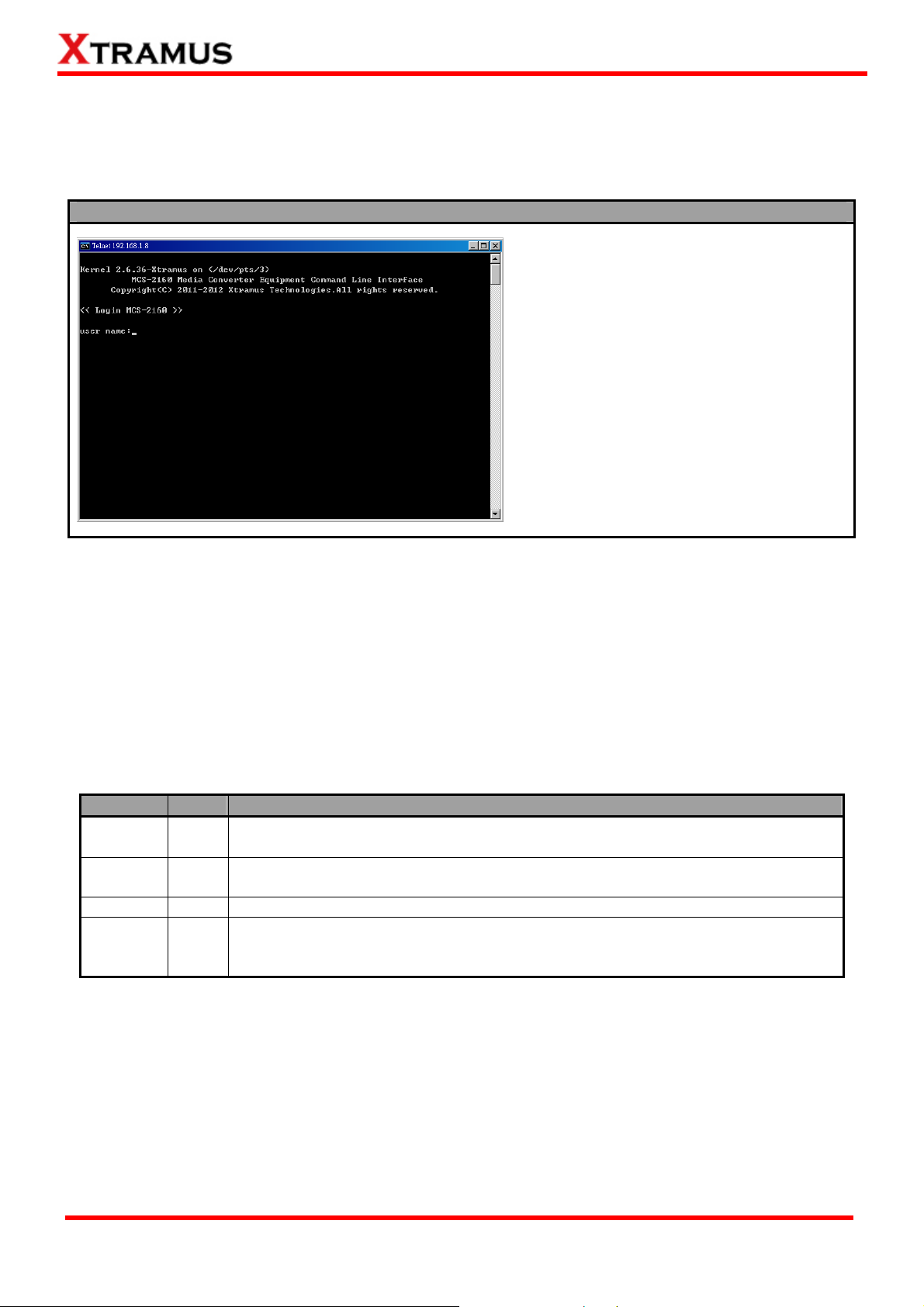
3.3 Managing MCS-2160 with Telnet
3.3.1. Telnet Settings for MCS-2160
Before setting Telnet for MCS-2160, please activate this service on your PC.
Establishing Connection with MCS-2160
1. Please click Start button on your
desktop, than choose: Run…Ætype
CMDÆclick OKÆtype telnet
192.168.1.8Æclick Enter, and you will
see the window on the left.
2. Type “admin” on the user name and
user password field to access the
MCS-2160 system.
*Note: If you change MCS-2160’s user name and password with MCS-2160’s configuration webpage, please log in
with the new user name and password here.
Please Note: If you log in the Telnet to access the MCS-2160 system, the previous accessed Web
Management will automatically log out from the MCS-2160 system.
3.2.2. MCS-2160 Telnet Commands
After logging in MCS-2160 via Telnet, a MCS-2160 Command Menu will be displayed, showing
MCS-2160’s Telnet commands. Please see the table down below for brief descriptions of MCS-2160
commands:
Command Alias Command Description
system sys
ip ip
cls cls
The system command allows you to view MCS-2160’s system information, make
system configurations, and upgrade MCS-2160’s firmware/FPGA.
The ip command allows you to view MCS-2160’s current IP settings or configure
these settings.
The cls command allows you to clear HyperTerminal screen.
The logout command allows you to log out. For security issues, it is
logout logout
recommended that you should log out if you’re not using the HyperTerminal
anymore.
Please see sections down below for more detailed information regarding to MCS-2160’s command.
XTRAMUS TECHNOLOGIES®
73
E-mail: sales@xtramus.com
Website: www.Xtramus.com
Page 74

A. MCS-2160 Telnet Command – system
Command Descriptions – system
chassis
show
information
fant
show
admin
user
guest
save
The system save command allows you to save the current settings to MCS-2160’s
NV-RAM. Please note that all unsaved settings will be lost after system reboot.
Show
Logip
system
safety
Set
show
enable
disable
value
The system show allows you to view MCS-2160’s Fan Tray status,
PCB/firmware/FPGA versions, as well as hardware temperature and
Counter of each module card.
The system show information command display the S/N, MAC, PCB
version and Firmware version of your MCS-2160.
Shows the detail information of your connected MCS-FANT.
The system user show command allows you to view the current
users and their passwords.
The system user admin [name | password] <name | password>
command allows you to change the user name and its password of
the user with administrator privilege. For example, if you type in
system user admin name test123 and press enter, a user named
test123 with administrator privilege will be created.
The system user guest [name | password] <name | password>
command allows you to change the user name and its password of
the user with guest privilege. For example, if you type in system user
guest name test123 and press enter, a user named test123 with
guest privilege will be created.
This command will show your current Syslog Receiver IP.
You can set your Syslog Receiver IP by typing command: sys logip
set xxx.xxx.xxx.xxx .
This command will show you the status of this function and the set
temperature threshold.
This command will enable the safety function.
This command will disable the safety function.
This command allows you to set the temperature threshold. You can
set as 60, 65, 70, 75 and 80 degrees centigrades.
The system update [firmware/fant] [remote file] [host ip]
commands allow you to upgrade MCS-2160’s firmware/fant. The
following descriptions are for upgrading MCS-2160’s firmware.
However, procedures for upgrading MCS-2160’s fant are quite the
same and can be related.
1. Please download and install first the Tftpd32 software from
update firmware/fant
internet.
2. Let the BIN file (firmware update file) inside a folder of your PC,
and open this file by open the folder with Tftpd32.
3. Set the Server Interface of Tftpd32 as 192.168.1.17.
4. On the Hyper Terminal screen, type in “sys update
[firmware/fant] [remote file] [host ip]” and click enter. Press Y
to proceed and start upgrading firmware, or press N to cancel.
5. MCS-2160 will reboot when finishing upgrading the firmware.
reset
reboot
*Note1: Please access the “Counter” by entering “sys show chassis”. Entering “0” to access the MCS-2160, than enter the
number of the slot of the module card that you want to analysis, and please confirm the commands for specific analysis.
*Note2: For updating your MCS-2160, please update first all the MGM_RTC_v1.1b002 version, and than update to the
MGM_RTC_v1.1b003 or newest.
The system reset command allows you to reset all MCS-2160’s settings back to the
default values.
The system reboot command allows you to reboot MCS-2160. Please note that all
unsaved settings will be lost after rebooting.
XTRAMUS TECHNOLOGIES®
74
E-mail: sales@xtramus.com
Website: www.Xtramus.com
Page 75

A. MCS-2160 HyperTerminal Command – system (Continue)
Command Descriptions – system
Shows the status of snmp v1/v2/v3.
Type command sys snmp readcommunity private or public to
set this option as private or public.
Type command sys snmp writecommunity private or public to
set this option as private or public.
Type command sys snmp securityname XXX to set the
username as XXX for snmp v3.
Type command sys authpassword XXX to set the authpassword
as XXX for snmp v3.
Type command sys authpassword XXX to set the privpassword
as XXX for snmp v3.
Type command sys snmp v2 enable or disable to enable or
disable the snmp v2 function.
Type command sys snmp v3 enable or disable to enable or
disable the snmp v3 function.
Type command sys time show to display the current time.
Type command sys time set xx : yy : zz to set your time as hour :
min : sec.
Type command sys date show to display the current date.
Type command sys date set xxxx : yy : zz to set your date as
year : month : day.
Type command sys mail show to display your alarm mail settings.
Type command sys mail enable to enable this function.
Type command sys mail disable to disable this function.
Type command sys mail server XXX to set your pop3 server
address as XXX.
Type command sys mail account XXX to set your e-mail box
account as XXX.
Type command sys mail password XXX to set your e-mail box
password as XXX.
Type command sys mail sma XXX to set your sender’s e-mail
address as XXX.
Type command sys mail dma XXX to set your destination e-mail
address as XXX.
Type command sys mail interval XX to set your e-mail sending
interval as XX, with setting range 1-65535 minutes.
system
show
readcommunity
writecommunity
snmp
securityname
authpassword
privpassword
snmp v2 enable/disable
snmp v3 enable/disable
show
time
set
show
date
set
show
enable
disable
server
account
password
mail
sma
dma
interval
Type command sys mail content XX to set your e-mail sending
content
interval as XX, in which the XX includes Port link state change,
DDMI, Card state change, Power supply change, temperature and
Fan tray warning.
*Note1: the authpassword, privpassword and mail password are case-sensitive.
*Note2: the authpassword, privpassword and mail password must be the same as your webpage settings.
*Note3: for Time and Date seetings please install battery on your XC-M667 module card.
XTRAMUS TECHNOLOGIES®
75
E-mail: sales@xtramus.com
Website: www.Xtramus.com
Page 76

A1. MCS-2160 HyperTerminal Command – system chassis
When you cascade numerous MCS-2160, the number of total chassis cascaded will be shown as the
figure above on Total chassis number. In this example of the figure above, we cascaded 2 MCS-2160
together which is Chassis ID 00 and 01, the number than is shown as Total chassis number 02.
Note: The system is able to cascade up to 10 MCS-2160.
For upgrading your XC module cards’ firmware, please follow the steps below:
1. Type sys show chassis command, select the correct Chassis ID number and number order of the
XC module cards.
2. Download and install the Tftpd32 software from internet.
3. Let the BIN file (firmware update file) inside a folder of your PC, and open this file by open the folder
with Tftpd32.
4. Set the Server Interface of Tftpd32 as 192.168.1.17.
5. On the Hyper Terminal screen, type in “sys update [firmware/fant] [remote file] [host ip]” and click
enter. Press Y to proceed and start upgrading firmware, or press N to cancel.
6. MCS-2160 will reboot when finishing upgrading the firmware.
XTRAMUS TECHNOLOGIES®
76
E-mail: sales@xtramus.com
Website: www.Xtramus.com
Page 77

B. MCS-2160 Telnet Command – ip
Command Descriptions – ip
show
status
mode
The ip show command allows you to view information of MCS-2160’s IP configuration.
The ip status command allows you to view information of MCS-2160’s IP status.
dhcp
static
The ip mode dhcp command allows you to set MCS-2160’s IP acquiring mode
to DHCP, allowing MCS-2160 to acquire IP automatically from DHCP server.
The ip mode static command allows you to set MCS-2160’s IP acquiring mode
to Static, allowing you to set IP/Subnet Mask/Gateway IP manually.
The ip address <IP Address> command allows you to set MCS-2160’s IP address. For
ip
address*
example, to set MCS-2160’s IP address to 192.168.1.20, please input the command “ip
address 192.168.1.20”.
The ip mask <Subnet Mask Address> command allows you to set MCS-2160’s subnet
mask*
mask address. For example, to set MCS-2160’s subnet mask address to 255.255.255.0,
please input the command “ip mask 255.255.255.0”.
The ip gateway <Gateway Address> command allows you to set MCS-2160’s gateway
gateway*
address. For example, to set MCS-2160’s subnet gateway address to 192.168.1.254,
please input the command “ip gateway 192.168.1.254”.
*MCS-2160’s default IP address/subnet mask/default gateway are 192.168.1.8/255.255.255.0/192.168.1.1
C. MCS-2160 Telnet Command – cls
Command Descriptions – cls
cls
The cls command allows you to clear Telnet screen.
D. MCS-2160 Telnet Command – logout
Command Descriptions – logout
logout
The logout command allows you to log out of MCS-2160’s Telnet configuration session.
XTRAMUS TECHNOLOGIES®
77
E-mail: sales@xtramus.com
Website: www.Xtramus.com
Page 78

4. MCS-2160 General Specifications
Model MCS-2160
Slot
Dimension
Temperature
Humidity
(non-condensing)
Built-in Sensors
¾ Operating: 0
¾ Operating: 0% ~ 85% RH ¾ Storage: 0% ~ 85% RH
Detecting system temperatures, rotation speed of fans, and system voltage
16 Slots for Installing XC Series Module Cards
o
C ~ 40oC (32oF ~ 104oF) ¾ Storage: 0oC ~ 50oC (32oF ~ 122oF)
441 mm x 310 mm x 88 mm
XTRAMUS TECHNOLOGIES®
78
E-mail: sales@xtramus.com
Website: www.Xtramus.com
Page 79

Note: Information and specifications contained in this document are subject to change without notice.
All products and company names are trademarks of their respective corporations.
Do not reproduce, redistribute or repost without written permission from Xtramus.
XTRAMUS TECHNOLOGIES®
Copyright © 2013 Xtramus Technologies, all rights reserved.
Doc # USM_MCS-2160 _V1.9.2_ENG_20131014.doc
79
E-mail: sales@xtramus.com
Website: www.Xtramus.com
 Loading...