

Page 1

LES-5160
Cat-5e simulator
USM Ver 1.1
Page 2

2
E-mail: sales@xtramus.com
Foreword
Copyright
Copyright © 2014 Xtramus Technologies, all rights reserved. The information contained in this document is the property of Xtramus
Technologies. No part of this publication shall be reproduced, stored in a retrieval system, or transmitted, in any form or by any
means, without the prior written permission of Xtramus Technologies.
Disclaimer
The information contained in this document is subject to change without notice and does not represent a commitment on the part of
Xtramus Technologies. The information in this document is believed to be accurate and reliable. However, Xtramus Technologies
assumes no responsibility or liability for any errors or inaccuracies that may appear in the document.
Trademarks
LES-5160 is a trademark or registered trademark of Xtramus Technologies. All other trademarks and registered trademarks are
the property of their respective owners.
Warranty
Xtramus Technologies warrants for the hardware provided along with this document under proper usage and conditions in normal
environment; any improper operation or in irregular environment may possibly cause this product NOT function well. For detailed
terms, please contact your local dealer.
Contact Information
Xtramus Technologies
E-mail: sales@xtramus.com
Website: www.xtramus.com
Tel: +886-2-8227-6611
Fax: +886-2-8227-6622
XTRAMUS TECHNOLOGIES®
Website: www.Xtramus.com
Page 3
3
E-mail: sales@xtramus.com
Date
Version
History
2014/07/23
1.0
First version
2014/12/03
1.1
Add the description of the three length simulation modes
Revision History
XTRAMUS TECHNOLOGIES®
Website: www.Xtramus.com
Page 4

4
E-mail: sales@xtramus.com
Table of Contents
Foreword ........................................................................................................................................ 2
Revision History ............................................................................................................................ 3
1. LES-5160 Overview ................................................................................................................... 5
1.1. General Descriptions of LES-5160 .................................................................................. 5
1.2. Features, Key Advantages, and Main Applications of LES-5160 ................................... 6
1.3. LES-5160 Functions Overview ......................................................................................... 7
1.3.1. LES-5160 Chassis ........................................................................................................ 7
1.3.2. LES-5160 Front Part .................................................................................................... 8
1.3.3. Modules ................................................................ ........................................................ 9
A. System Module– XLE-SFAN .......................................................................................10
B. System Module– XLE-M667 ........................................................................................ 11
C. System Module Card – XLE-CASC .............................................................................12
D. Cat-5e Simulation Module – XLE-C5E ........................................................................13
1.3.4. LES-5160 Back Part ................................................................................................... 14
A. XLE-RFAN ....................................................................................................................15
2. LES-5160 Installation ................................ .............................................................................. 16
2.1. Choices of UTP Cable..................................................................................................... 16
2.2. Hardware Installation ..................................................................................................... 17
2.2.1. Bracket installation .................................................................................................... 17
2.2.2. Modules Installation .................................................................................................. 19
2.2.3. Power Module ............................................................................................................ 21
2.2.4. Fan Module ................................................................................................................. 22
3. LES-5160 Management ........................................................................................................... 23
3.1. Managing LES-5160 with Management Webpage ......................................................... 23
3.1.1. Accessing LES-5160 Management Webpage ........................................................... 24
3.1.1.1. Access with IP address ......................................................................................24
3.1.1.2. Access with UPnP service ..................................................................................24
3.1.3. LES-5160 Management Webpage – System ............................................................. 27
3.1.3.1. System Information.............................................................................................27
3.1.3.2. Module Information .............................................................................................28
3.1.3.3. IP settings ............................................................................................................28
3.1.4. LES-5160 Management Webpage – Management .................................................... 30
A. Chassis Overview .......................................................................................................30
B. Cable Length Settings ................................................................................................31
C. Characteristic Chart ................................................................ ....................................31
3.1.5. LES-5160 Management Webpage – Maintenance .................................................... 32
A. Update Firmware .........................................................................................................32
a. Management Card ..........................................................................................32
b. Single Subcard ...............................................................................................32
c. Multi Subcard .................................................................................................32
B. Save Changes ..............................................................................................................33
C. Factory Defaults ..........................................................................................................34
D. System Reboot ............................................................................................................34
4. LES-5160 General Specifications ........................................................................................... 35
XTRAMUS TECHNOLOGIES®
Website: www.Xtramus.com
Page 5
5
E-mail: sales@xtramus.com
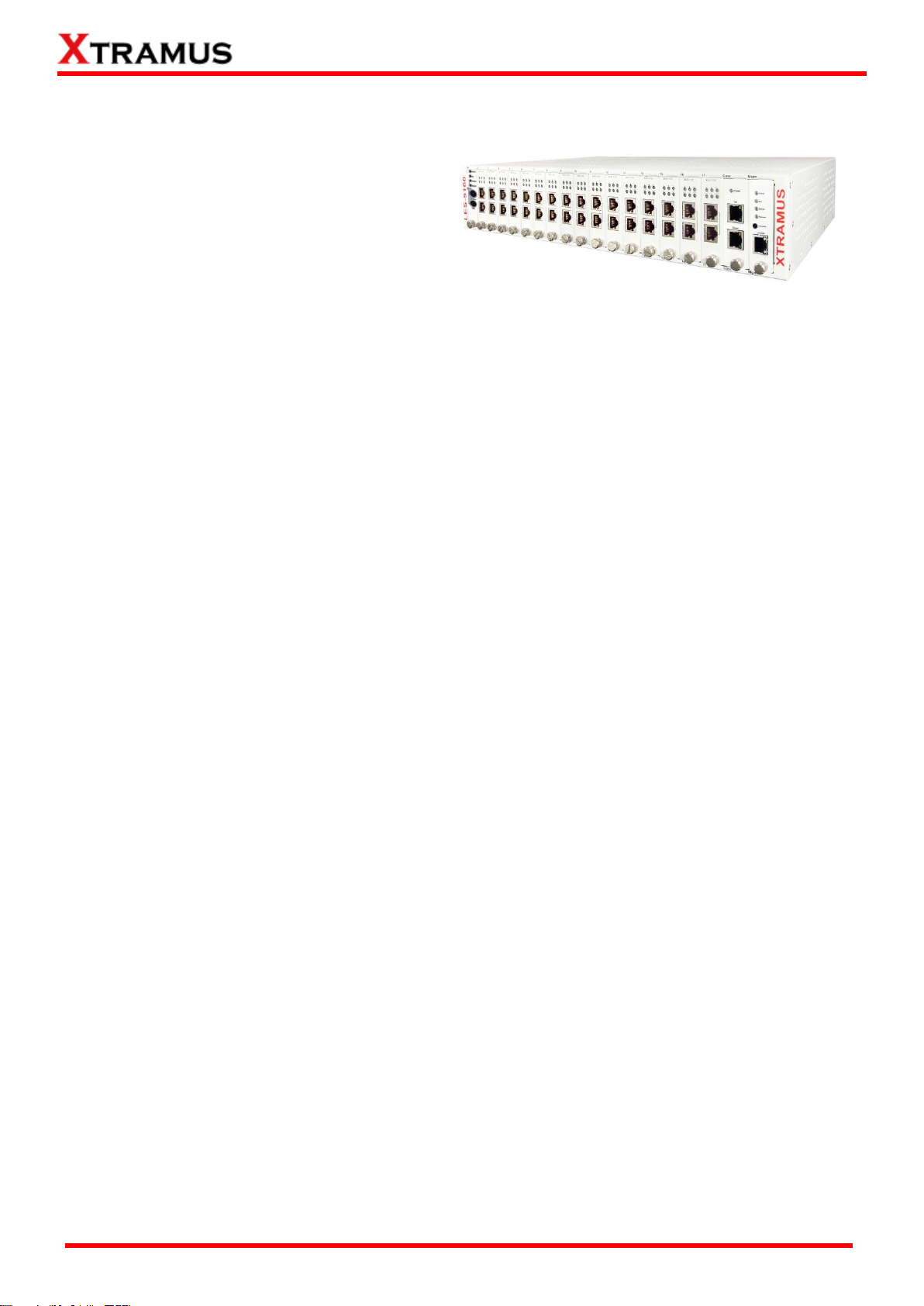
1. LES-5160 Overview
1.1. General Descriptions of LES-5160
LES-5160 is a 16-slot Ethernet cable Cat-5e
simulator. Upon different commands, it can
simulate different network cable lengths,
including 3 Modes: Bypass, Short, 100m. It can
be used independently or jointly with other
devices.
Combined with XLE series modules, LES-5160 cable length simulator provides RJ45 interface, which can
support the protocols such as 10Base-T, 100BASE-TX, and 1000BASE-T, thus making your network
verification system more complete.
All XLE series modules are equipped with real-time LEDs which display the status of the system and the
simulating cable length, thus allowing users to view network status easily.
LES-5160 cable length simulator provides an easy-to-access Management Webpage, allowing users to
view system status, set the simulating length for the XLE series modules and upgrade firmware.
Moreover, XLE-CASC modules allow you to cascade multiple LES-5160 chassis for managing these
chassis simultaneously.
XTRAMUS TECHNOLOGIES®
Website: www.Xtramus.com
Page 6
6
E-mail: sales@xtramus.com
1.2. Features, Key Advantages, and Main Applications of LES-5160
Features
Simulates Ethernet cable Cat-5e in different lengths
Supports easy-to-access Management Webpage, allowing users to view system status, set the
simulating length for the XLE series modules and upgrade firmware/FPGA
Multiple LES-5160 chassis can be cascaded for system management
Replaceable redundancy power modules for AC & DC power
Key Advantages
Provide the network environments under various cable lengths, saving the cable deploying work
in practical
Provide reliable long-distance connection
Provide cable simulation function of a very long distance, saving plenty of space for placing the
real cables
Web management
Main Applications
Test for different cable length simulations in laboratories
Test for multiple DUTs with long cables simultaneously in production
Provide simple and convenient mass production software by Xtramus technologies.
Provide the API & Library files for development of other applications.
XTRAMUS TECHNOLOGIES®
Website: www.Xtramus.com
Page 7
7
E-mail: sales@xtramus.com
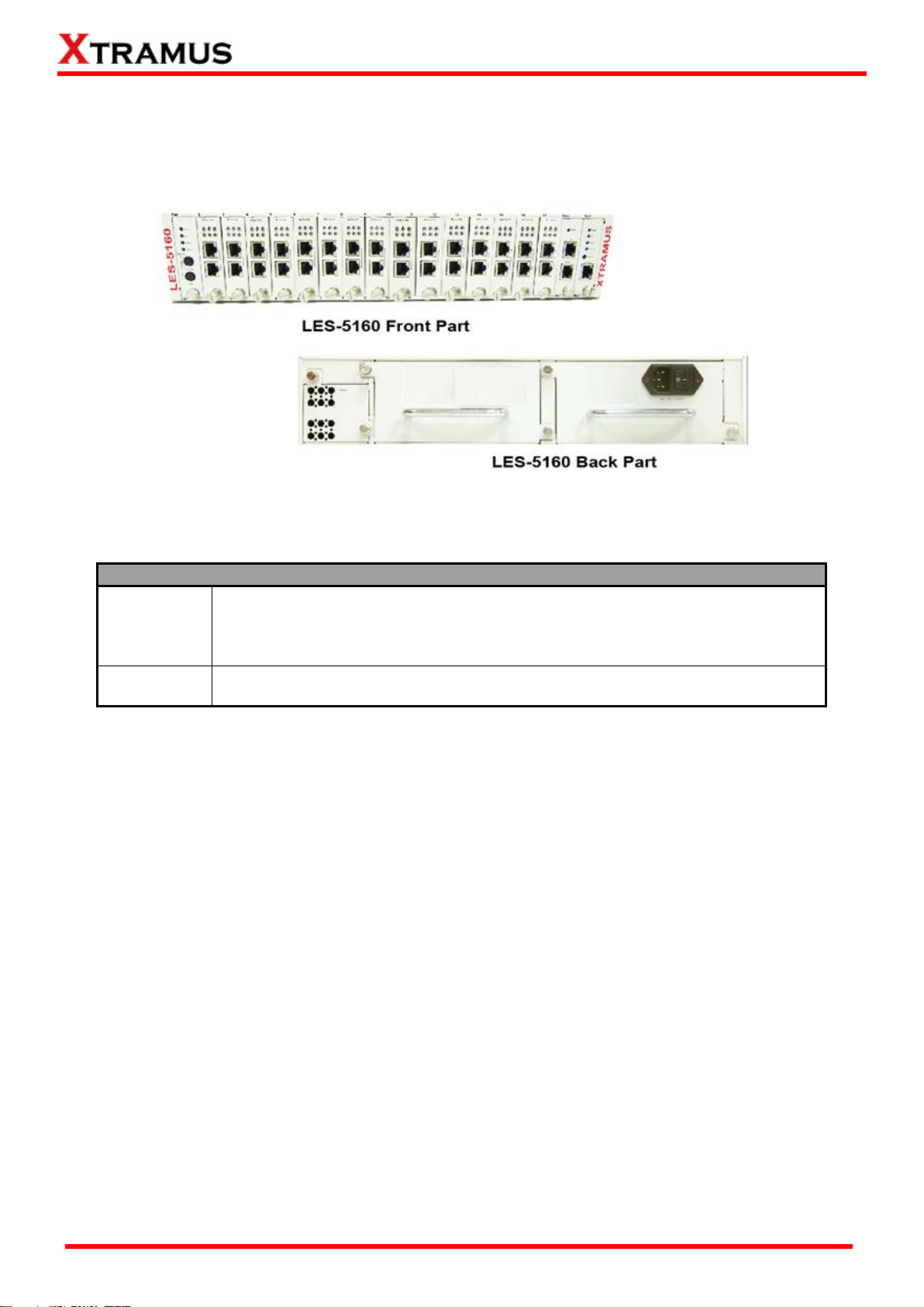
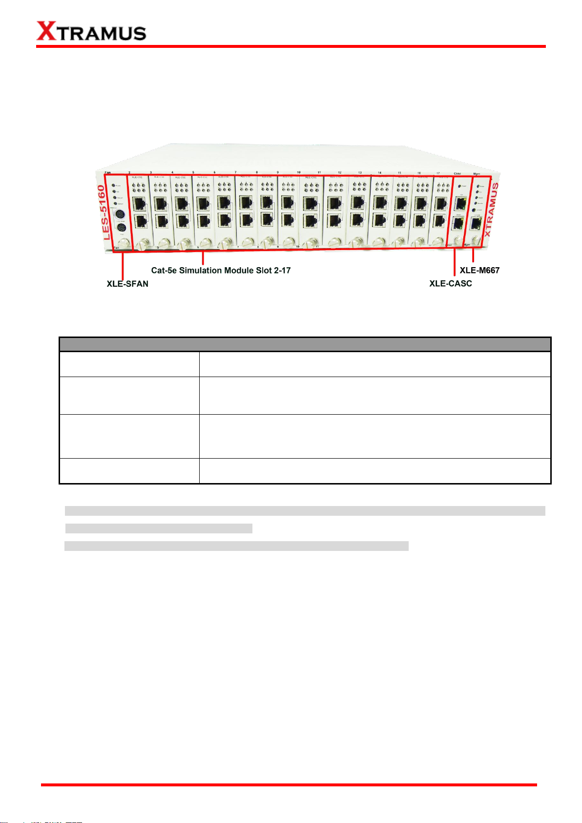
LES-5160 Chassis Overview
Front Part
LES-5160 has 16 slots for installation of modules, where each module card
provides cable Cat-5e simulation functions. Besides, the Front Part provides 3
slots for installing the Fan module, CASC module and management module.
Please see “1.3.2. LES-5160 Front Part” for more information.
Back Part
LES-5160’s back part includes 3 different slots. Please see “1.3.4. LES-5160
Back Part” for more detailed information.
1.3. LES-5160 Functions Overview
1.3.1. LES-5160 Chassis
LES-5160’s chassis consists two parts: Front Part and Back Part. The figure above shows the chassis
of LES-5160.
XTRAMUS TECHNOLOGIES®
Website: www.Xtramus.com
Page 8
8
E-mail: sales@xtramus.com
LES-5160 Front Part
XLE-SFAN
It is a fan module card pre-installed in the front part of LES-5160
chassis.
XLE-M667
It is a module card pre-installed in LES-5160 chassis with 1
Management port for accessing the Management Webpage and 1
Console port for accessing the terminal settings.
XLE-CASC
It is a module card pre-installed in LES-5160 with 2 ports where each
port can connect another LES-5160 providing simultaneous access to
the Management Webpage.
Cable Cat-5e simulation
module Slots 2-17
Cable Cat-5e simulation modules can be inserted in each of slot 2-17.
WARNING1: XLE-SFAN, XLE-M667 and XLE-CASC do not support hot swap, please, do not pull out the XLE-SFAN, XLE-M667 and
XLE-CASC modules when the system is power on.
*WARNING2: Do not insert the XLE-M667, XLE-CASC or XLE-SFAN module to the wrong slot.
1.3.2. LES-5160 Front Part
As mentioned in “1.3.1. LES-5160 Chassis”, LES-5160 has 16 slots for installation of cable Cat-5e
simulation modules and 3 slots for installing the Fan, CASC and Management module. Please see the
sections down below for more detailed information/specification for LES-5160 and the modules.
XTRAMUS TECHNOLOGIES®
Website: www.Xtramus.com
Page 9
9
E-mail: sales@xtramus.com
Module Card Type
Module Card
Description
System Modules
XLE-SFAN
Provide ventilation for the LES-5160
chassis
XLE-M667
Allow users to view counters/perform
system maintenance
XLE-CASC
Cascade multiple LES-5160 chassis
Cat-5e Simulation
Modules
XLE-C5E
Modules for Cat-5e simulation. These
Cat-5e simulation modules can be installed
in slot 2~17 and support hot-swap.
1.3.3. Modules LES-5160’s modules can be divided into two categories: System Modules and Cat-5e Simulation
Modules.
Please see the sections down below for more detailed information regarding to LES-5160 modules.
XTRAMUS TECHNOLOGIES®
Website: www.Xtramus.com
Page 10
10
E-mail: sales@xtramus.com
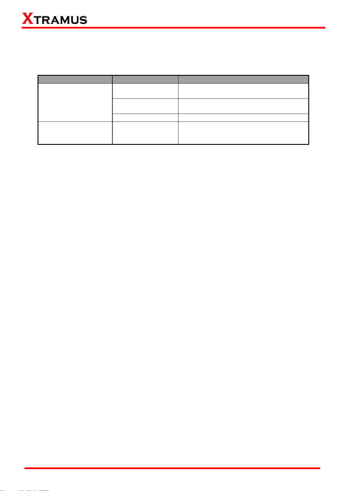
Interface Ports
CTRL + PWR
Preserved for future use
PWR
Preserved for future use
LED
Power
Green ON
XLE-SFAN is power on.
Green OFF
XLE-SFAN is power off.
Sys
Green ON
XLE-SFAN is powering up properly.
Green OFF
XLE-SFAN is power off.
Status 0
Preserved for future use
Status 1
Preserved for future use
A. System Module– XLE-SFAN
The XLE-SFAN is delivered with your LES-5160 chassis, and shall be installed on the Fan slot located
on the far left side of LES-5160 chassis. This module provides ventilation for the LES-5160 chassis.
*Note: XLE-SFAN does not support hot-swap. Please do not draw the XLE-SFAN module from LES-5160 chassis when
the system is power on.
XTRAMUS TECHNOLOGIES®
Website: www.Xtramus.com
Page 11
11
E-mail: sales@xtramus.com
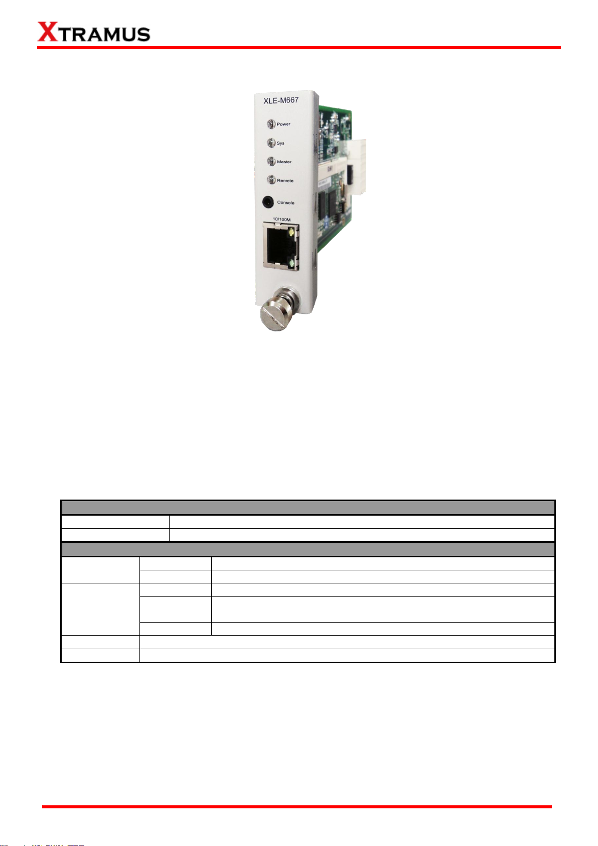
Interface Ports
Console Port
One 2.5mm Phone Jack Port for managing LES-5160 via serial port
Management Port
One 10/100M RJ45 Port for managing LES-5160 via management webpage
LED
Power
Green ON
XLE-M667 is power on.
Green OFF
XLE-M667 is power off.
Sys
Yellow ON
XLE-M667 is booting and preparing for test.
Green ON
(Blinking)
XLE-M667 is booting properly and is ready for test.
Green OFF
XLE-M667 is power off.
Master
Preserved for future use.
Remote
Preserved for future use.
*Note: XLE-M667 does not support hot-swap. Please do not pull out the XLE-M667 module card from LES-5160
chassis when the system is power on.
B. System Module– XLE-M667
The XLE-M667 is delivered with your LES-5160 chassis, and shall be installed on the Mgm slot
located on the far right side of LES-5160 chassis. This module allows you to manage LES-5160
chassis via the management webpage.
To access the Management Web Page of LES-5160, please connect a RJ45 cable between the
Management port of LES-5160 and your PC.
To configure LES-5160 on your PC through serial port, please connect a 2.5mm Phone Jack to
RS232 cable between your PC and the Console Port of LES-5160.
XTRAMUS TECHNOLOGIES®
Website: www.Xtramus.com
Page 12

12
E-mail: sales@xtramus.com
Interface Ports
Port (Up)
One 10/100M RJ45 Port for cascading another LES-5160 chassis
Port (Down)
One 10/100M RJ45 Port for cascading another LES-5160 chassis
LED
Power
Green ON
LES-5160 is powered on
Green OFF
LES-5160 is powered off
*Note: XLE-CASC does not support hot-swap. Please do not draw the XLE-CASC module card from LES-5160
chassis when the system is power on.
C. System Module Card – XLE-CASC
The XLE-CASC is delivered with your LES-5160 chassis, and shall be installed on the CASC slot
located on the right side of LES-5160 chassis (next to XLE-M667 module card). This module allows
you to cascade multiple LES-5160 chassis.
To cascade the LES-5160, please inter-connect the Up port or Down port of the chassis with the RJ45
cables. For the cascaded chassis, you can manage all the chassis through one integrated web page.
XTRAMUS TECHNOLOGIES®
Website: www.Xtramus.com
Page 13

13
E-mail: sales@xtramus.com
XLE-C5E Front Panel Specification
Interface
Port A
RJ45
Port B
RJ45
Data Transfer Rate
1000 Mbps
Ethernet Mode
10Base-T, 100BASE-TX, and 1000BASE-T
LED Status
Pwr
Green ON
XLE-C5E is powered on.
Green OFF
XLE-C5E is powered off.
1m
Green ON
XLE-C5E is booting properly and is ready for
tests.
Yellow ON
Error occurred when booting XLE-7S81.
100m
Green ON
Port A/B is connected.
Green Blinking
Port A/B is transmitting/receiving data.
▇
Preserved for future use.
▲
Preserved for future use.
Note: All LEDS will be off when upgrading FPGA/Firmware
D. Cat-5e Simulation Module – XLE-C5E
XTRAMUS TECHNOLOGIES®
Website: www.Xtramus.com
Page 14

14
E-mail: sales@xtramus.com
LES-5160 Back Part Description
XLE-RFAN
It is a fan module card pre-installed in back part of LES-5160
chassis.
XCP-A1W-300
It is a power module based on AC power source.
1.3.4. LES-5160 Back Part
As mentioned in “1.3.1. LES-5160 Chassis”, LES-5160’s back part includes 3 different slots for installing
the DC module, AC module and Fan module.
XTRAMUS TECHNOLOGIES®
Website: www.Xtramus.com
Page 15

15
E-mail: sales@xtramus.com
A. XLE-RFAN
The XLE-RFAN consists of two fans as shown in the picture below. After installing XLE-RFAN, the
Management Web Page will show the operation of XLE-RFAN, please see the 3.1.4. LES-5160
Management Webpage – Management for more information.
B. XCP-A1W-300
XCP-A1W-300 is a power module providing power source of 300W AC Redundant SPS (Vin
90~240VAC).
The Power Jack of XCP-A1W-300 is Male IEC 320 Receptable. To activate XCP-A1W-300 &
XLEP-AC-100, just turn on/off the O/I button after connecting a power source cable in Male IEC 320
Receptable.
XTRAMUS TECHNOLOGIES®
Website: www.Xtramus.com
Page 16

16
E-mail: sales@xtramus.com
2. LES-5160 Installation
LES-5160 is a chassis with 16 slots for installation of Cat-5e simulation modules. Installing LES-5160 is
very easy and simple: all you have to do is to plug the proper UTP cables into LES-5160 ports like a
general Ethernet switch without any extra configurations. However, selecting the proper physical media
and applications in your network environment is crucial when installing LES-5160. Besides, using the
proper method for installing Cat-5e simulation modules into LES-5160’ slots is also crucial. Please see the
sections down below for detailed information regarding to physical media types, LES-5160 application and
the proper method for installing a Cat-5e simulation module.
2.1. Choices of UTP Cable
For better performances of LES-5160, please try to use the Cat 5e cable when connecting it to
the DUT.
XTRAMUS TECHNOLOGIES®
Website: www.Xtramus.com
Page 17

17
E-mail: sales@xtramus.com
Steps for installing a Bracket in LES-5160
First of all, you must have an Empty Slot for the
Installation of a Bracket.
Attach the Bracket’s Latch on the internal face of
Chassis’ Latch.
2.2. Hardware Installation
Please follow the steps shown below for a better understanding on how to install the hardware of
LES-5160.
2.2.1. Bracket installation
XTRAMUS TECHNOLOGIES®
Website: www.Xtramus.com
Page 18

18
E-mail: sales@xtramus.com
Steps for installing a Bracket in LES-5160
After attaching the Bracket’s Latch on the internal
face of Chassis’ Latch, let this point be a fix central
rotation point and push the bottom part of Bracket
into LES-5160.
Lock the Captive Screw into the LES-5160 to fix
the Bracket into LES-5160.
XTRAMUS TECHNOLOGIES®
Website: www.Xtramus.com
Page 19

19
E-mail: sales@xtramus.com
Steps for installing a XLE-C5E module in LES-5160
Aim the border side of a Cat-5e simulation
module with the LES-5160 internal slide road,
and push this module into LES-5160.
Please, make sure if the XLE-C5E module is
well fixed into LES-5160 by pushing the bracket
of the module into LES-5160.
2.2.2. Modules Installation
XTRAMUS TECHNOLOGIES®
Website: www.Xtramus.com
Page 20

20
E-mail: sales@xtramus.com
Steps for installing a XLE-C5E module in LES-5160
Lock the Captive Screw into the LES-5160 to fix
the module into LES-5160.
XTRAMUS TECHNOLOGIES®
Website: www.Xtramus.com
Page 21

21
E-mail: sales@xtramus.com
Steps for installing a XCP-A1W-300
Installing a XCP-A1W-300 into LES-5160 is
quite simple. First of all, attach the Power
Module into the respective slot of LES-5160
and push the handle of the Power Module into
the slot. After the Bracket of the Power Module
reaches the LES-5160, lock the captive screw
into LES-5160 as shown by arrows 4 and 5.
Note: The XCP-A1W-300 doesn’t support
hot swap. Please don’t remove Power
Module during System operation.
2.2.3. Power Module
XTRAMUS TECHNOLOGIES®
Website: www.Xtramus.com
Page 22

22
E-mail: sales@xtramus.com
Steps for installing the XLE-SFAN
The XLE-SFAN comes with your LES-5160
chassis, and shall be installed on the Fan slot
located on the far left side of LES-5160
chassis. This module card provides
ventilation for the LES-5160 chassis.
be seriously damaged.
2.2.4. Fan Module
Warning: The CTRL + PWR port and PWR port are preserved for future use. Please do not conduct any cable connections, or LES-5160 may
XTRAMUS TECHNOLOGIES®
Website: www.Xtramus.com
Page 23

23
E-mail: sales@xtramus.com
3. LES-5160 Management
You can configure the settings and check the running status of LES-5160 on the web browser.
3.1. Managing LES-5160 with Management Webpage
Before accessing to LES-5160’s management webpage, please connect the network interfaces between
the PC and the manage card “XLE-M667” and configure the IP address for LES-5160. Please refer to the
picture down below to configure the IP address. The default IP address is 192.168.1.8.
XTRAMUS TECHNOLOGIES®
Website: www.Xtramus.com
Page 24

24
E-mail: sales@xtramus.com
Access the LES-5160’s management webpage through the UPnP service
Click Computer→manage to enter the
Computer Management interface.
Click Services and Applications→Services,
then the available services will be listed in the
middle pane. Ensure that the “SSDP Discovery”
and “UPnP device Host” are started.
If the service is not started, double click it and a
window will pop up. Then click start to activate
the service. The picture just takes the SSDP
Discovery Properties window for an example.
3.1.1. Accessing LES-5160 Management Webpage
3.1.1.1. Access with IP address
To access LES-5160’s management webpage, please open your web browser, and type in LES-5160’s
default IP address (192.168.1.8) in the web browser’s URL field. If you’ve changed LES-5160’s IP
address, please input the IP address you’ve changed to.
3.1.1.2. Access with UPnP service
You can access the LES-5160’s management webpage through the UPnP service provided by windows
(windows XP, windows7 or versions above). It is very convenient if you forget the IP address you’ve set
or under the condition of not connecting to the console.
XTRAMUS TECHNOLOGIES®
Website: www.Xtramus.com
Page 25

25
E-mail: sales@xtramus.com
Go to Network. You can see the “LES-5160”
device is listed.
If you cannot see the “LES-5160”, please turn off
your firewall and then try again.
Double click the icon of “LES-5160” to enter the
management webpage.
XTRAMUS TECHNOLOGIES®
Website: www.Xtramus.com
Page 26

26
E-mail: sales@xtramus.com
LES-5160 Management Webpage Overview
A
Menu Bar
Home: Link to the home page.
About: Brief introduction of LES-5160.
Contact: Contact information of Xtramus Co.Ltd.
B
Model Name
This field displays the model name “LES-5160”.
C
Setting Options
The Setting Options contains options for LES-5160 settings,
information, and statistics, which can be divided into:
System: You can view system information here in this field.
Management: This option allows you to view the chassis status,
characteristic curves and set the cable length.
Maintenance: This option allows you to upgrade the firmware,
save the settings and reset to factory defaults.
D
Main Display Screen
The Main Display Screen displays the detailed information of the above
setting options.
3.1.2. LES-5160 Management Webpage – Overview
XTRAMUS TECHNOLOGIES®
Website: www.Xtramus.com
Page 27

27
E-mail: sales@xtramus.com
System Information
Model Name
The model of the device “LES-5160”
Serial Number
LES-5160’s serial number.
MAC Address
LES-5160’s MAC address.
Hardware version
PCB Version of XLE-M667.
Firmware Version
LES-5160’s current firmware version.
IP Status
3.1.3. LES-5160 Management Webpage – System
The management page provides two information interfaces: System Information and Module
Information. You can access to the two interfaces by click the links at the upper left corner.
3.1.3.1. System Information
System Information displays LES-5160’ system information including:
XTRAMUS TECHNOLOGIES®
Website: www.Xtramus.com
Page 28

28
E-mail: sales@xtramus.com
System Information
IP Mode
This field displays how LES-5160 acquires its IP address.
Static: LES-5160’s IP, subnet mask, and gateway addresses are
assigned manually.
DHCP: LES-5160’s IP, subnet mask, and gateway addresses are
assigned automatically by a DHCP server.
IP Address
LES-5160’s IP address.
Subnet Mask
LES-5160’s subnet mask.
Gateway IP
LES-5160’s gateway address.
3.1.3.2. Module Information
This screen displays the detailed information of the module, including the slot number, module name,
firmware version, firmware date, serial number and MAC address.
3.1.3.3. IP settings
IP Settings: Allows you to set how LES-5160 will acquire its IP, subnet mask, and gateway addresses.
Also, you could input these addresses manually here.
Click IP Settings, the following screen appears.
XTRAMUS TECHNOLOGIES®
Website: www.Xtramus.com
Page 29

29
E-mail: sales@xtramus.com
IP Settings
Mode
You can choose how LES-5160 acquires its IP, subnet mask, and
gateway addresses. There are two modes available:
Static: You have to input LES-5160’s IP, subnet mask, and
gateway addresses manually in the fields down below.
DHCP: LES-5160 acquires its IP, subnet mask, and gateway
addresses automatically from network’s DHCP server.
Address
You can input LES-5160’s IP address here in this field.
Subnet Mask
You can input LES-5160’s subnet mask here in this field.
Gateway
You can input LES-5160’s gateway address here in this field.
Apply
Apply the changes you’ve made here.
*Note1: The default IP address for LES-5160 is 192.168.1.8.
XTRAMUS TECHNOLOGIES®
Website: www.Xtramus.com
Page 30

30
E-mail: sales@xtramus.com
Chassis Overview
A
Name of the module
B
Display the operation status of each module and cable length
settings
C
Display the communication status of the modules: when the
module is initiating, the RJ45 ports are brown , indicating the
module is establishing communication with the management card
and after that the RJ45 ports will be green . Now the module is
ready.
*Note: if the module cannot be started normally, the RJ45 ports will not
turn to green.
3.1.4. LES-5160 Management Webpage – Management There are 3 options available for Management, including Chassis Overview, Cable Length Settings, and Characteristic Chart.
A. Chassis Overview
This page can display the status of the modules installed in the LES-5160 chassis and the cable
length settings. The page is shown as follows.
XTRAMUS TECHNOLOGIES®
Website: www.Xtramus.com
Page 31

31
E-mail: sales@xtramus.com
B. Cable Length Settings
This page is used to individually set the simulation cable length for each module. There are three
modes to choose, which are Bypass, Short and 100m, respectively regarding to 1m, 10m and 100m.
The page is shown as follows.
Click Apply to make your settings here effective.
C. Characteristic Chart
This page is used to view the characteristic chart of a certain module. The page is shown as follows.
Slot ID: select the slot ID of the module to see its characteristic chart.
Line: select the wire pairs. There are four pairs (Pair-12, Pair-36, Pair-45, and Pair-78) and you can also
choose to display all the four pairs (All-Pair).
In the chart, the x-axis denotes frequencies (64 points in total but 32 points for IE8) while the Y-axis
denotes the decibel values.
XTRAMUS TECHNOLOGIES®
Website: www.Xtramus.com
Page 32

32
E-mail: sales@xtramus.com
Management Card
Browse…
Click the Browse… button to choose the firmware file you would like to
upgrade. LES-5160’s firmware files are in the format of “*.bin”.
Apply
Click this button to start upgrading LES-5160’s firmware.
Single Subcard
Slot ID
Click the scroll down menu to select the module you want to upgrade firmware
on.
Browse…
Click the Browse… button to choose the firmware file you would like to
upgrade. LES-5160’s firmware files are in the format of “*.bin”.
Apply
Click this button to start upgrading LES-5160’s firmware.
3.1.5. LES-5160 Management Webpage – Maintenance Four options are available in the Maintenance configuration webpage: Upgrade Firmware, Save
Changes, Set Factory Defaults and System Reboot.
A. Update Firmware
This function is used to upgrade the firmware of the management card and the Cat-5e cable
simulation modules. There are three modes for this function, including Management Card, Single
Subcard, and Multi Subcards.
a. Management Card
This mode is to upgrade the firmware of management card.
b. Single Subcard
This mode is to upgrade the firmware of a single XLE-C5E module.
c. Multi Subcard
This mode is to upgrade multiple XLE-C5E modules at the same time. The system will upgrade
the firmware of the selected modules in sequence.
XTRAMUS TECHNOLOGIES®
Website: www.Xtramus.com
Page 33

33
E-mail: sales@xtramus.com
Multi Subcard
Module list
Select the available modules according to their slot IDs, as shown in the picture
down below.
Browse…
Click the Browse… button to choose the firmware file you would like to
upgrade. LES-5160’s firmware files are in the format of “*.bin”.
Apply
Click this button to start upgrading LES-5160’s firmware. And then the firmware
of the selected modules will be upgraded in sequence.
Save Changes
Save
If you don’t save the settings you’ve made via LES-5160’s management
webpage, all settings will be erased after rebooting LES-5160. Click the “Save”
button to save the settings to LES-5160.
B. Save Changes
XTRAMUS TECHNOLOGIES®
Website: www.Xtramus.com
Page 34

34
E-mail: sales@xtramus.com
Factory Defaults
Restore
You can set all LES-5160’s settings to default by clicking the “Restore” button.
System Reboot
Reboot
You can reboot LES-5160 by clicking the “Reboot” button. Please note that all
unsaved settings will be lost after system reboot.
C. Factory Defaults
D. System Reboot
XTRAMUS TECHNOLOGIES®
Website: www.Xtramus.com
Page 35

35
E-mail: sales@xtramus.com
Note: Information and specifications contained in this document are subject to change without notice.
Doc # USM_LES-5160 _V1.0_ENG_20141203.doc
Model
LES-5160
Slot
16 Slots for Installing XLE Series Modules
Dimension
441 mm x 310 mm x 88 mm
Temperature
Operating: 0
o
C ~ 40oC (32oF ~ 104oF)
Storage: 0
o
C ~ 50oC (32oF ~ 122oF)
Humidity
(non-condensing)
Operating: 0% ~ 85% RH
Storage: 0% ~ 85% RH
Built-in Sensors
Detecting system temperatures, rotation speed of fans, and system voltage
4. LES-5160 General Specifications
All products and company names are trademarks of their respective corporations.
Copyright © 2014 Xtramus Technologies, all rights reserved.
Do not reproduce, redistribute or repost without written permission from Xtramus.
XTRAMUS TECHNOLOGIES®
Website: www.Xtramus.com
 Loading...