

Page 1

APMPT-4 V2.1b004
User’s Manual
USM Ver 2.4
Page 2

2
E-mail: sales@xtramus.com
Website: www.Xtramus.com
XTRAMUS TECHNOLOGIES®
Foreword
Copyright
Copyright © 2014 Xtramus Technologies, all rights reserved. The information contained in this document is the property of Xtramus
Technologies. No part of this publication shall be reproduced, stored in a retrieval system, or transmitted, in any form or by any
means, without the prior written permission of Xtramus Technologies.
Disclaimer
The information contained in this document is subject to change without notice and does not represent a commitment on the part of
Xtramus Technologies. The information in this document is believed to be accurate and reliable. However, Xtramus Technologies
assumes no responsibility or liability for any errors or inaccuracies that may appear in the document.
Trademarks
APMPT-4 is a trademark or registered trademark of Xtramus Technologies. All other trademarks and registered trademarks are the
property of their respective owners.
Warranty
Xtramus Technologies warrants for the hardware provided along with this document under proper usage and conditions in normal
environment; any improper operation or in irregular environment may possibly cause this product NOT function well. For detailed
terms, please contact your local dealer.
Contact Information
Xtramus Technologies
E-mail: sales@xtramus.com
Website: www.xtramus.com
Tel: +886-2-8227-6611
Fax: +886-2-8227-6622
Page 3

3
E-mail: sales@xtramus.com
Website: www.Xtramus.com
XTRAMUS TECHNOLOGIES®
Date
USM Version
Revision contents
2014/08/22
2.4
1. Delete Serial Port test task and its task descriptions.
2. Delete Telnet test task.
3. Add Terminal test task which combine console and
telnet.
4. Add Line Emulate test task.
Revision
Page 4

4
E-mail: sales@xtramus.com
Website: www.Xtramus.com
XTRAMUS TECHNOLOGIES®
Table of Contents
Foreword ........................................................................................................................................ 2
Revision ......................................................................................................................................... 3
1. APMPT-4 Overview .................................................................................................................... 6
1.2. Specifications & System Requirements .......................................................................... 6
1.3. Function Description ........................................................................................................ 7
1.3.1. Performance Task in Layer 1 (PT1) ............................................................................. 7
1.3.2. Performance Task in Layer 2 (PT2) ............................................................................. 7
1.3.3. Performance Tasks in Layer 3 (PT3) ......................................................................... 10
1.3.4. PoE (Power over Ethernet) Test ................................................................................ 11
1.3.5. AC Test ....................................................................................................................... 12
1.3.6. Terminal Test .............................................................................................................. 12
1.3.7. General Test ............................................................................................................... 12
1.3.8. Customization Test .................................................................................................... 13
2. Software/Hardware Installation for APMPT-4 ......................................................................... 14
2.1. Install/Uninstall APMPT-4 on PC .................................................................................... 14
2.2. Hardware Installation...................................................................................................... 18
3. APMPT-4 Overview .................................................................................................................. 19
3.1. Starting APMPT-4 ............................................................................................................ 19
3.2. APMPT-4/NuServer Main Window Overview ................................................................. 24
3.3. Menu Bar ......................................................................................................................... 26
3.3.1. File .............................................................................................................................. 26
3.3.2. View ............................................................................................................................ 27
3.3.3. Tools ........................................................................................................................... 28
3.3.4. Security ...................................................................................................................... 29
3.3.5. Language.................................................................................................................... 30
3.3.6. Help ............................................................................................................................. 30
3.4. Quick Launch Buttons ................................................................................................... 31
3.5. DUT Information ............................................................................................................. 32
3.6. Task Running Status ...................................................................................................... 33
3.7. Status Bar ........................................................................................................................ 33
3.8. System Status ................................................................................................................. 33
3.9. Test Control & Status ..................................................................................................... 33
4. Creating Task via New Model Wizard ..................................................................................... 35
4.1. Selecting Active Ports from Installed Module Cards .................................................... 36
4.2. Making Settings on Option – New Model Window ........................................................ 39
4.2.1. Configuring Environment Setting ............................................................................. 40
4.2.2. Adding/Removing Tasks via Task List Setting ......................................................... 45
4.2.3. Configuring Tasks Listed on List of Selected Tasks ............................................... 49
5. APMPT-4 Detail Task Setting .................................................................................................. 51
5.1. Test Tasks - Layer 1: DUT-OSC ...................................................................................... 52
5.1.1. Setup .......................................................................................................................... 52
5.1.2. Criteria ........................................................................................................................ 52
5.1.3. Misc ............................................................................................................................ 52
5.1.4. Help ............................................................................................................................. 53
5.2. Test Tasks – Layer 2 ....................................................................................................... 54
5.2.1. Port Map ..................................................................................................................... 54
5.2.2. Media Type ................................................................................................................. 55
5.2.3. Packet ......................................................................................................................... 58
5.2.4. Learning ..................................................................................................................... 63
5.2.5. Criteria ........................................................................................................................ 64
5.2.6. Misc ............................................................................................................................ 66
5.2.7. Help ............................................................................................................................. 67
5.3. Test Tasks – Layer 3 ....................................................................................................... 68
5.3.1. Port Map IP Setting ............................................................................................... 68
Page 5

5
E-mail: sales@xtramus.com
Website: www.Xtramus.com
XTRAMUS TECHNOLOGIES®
5.3.2. Performance Task Layer 3 – PT3-Ping ................................ ..................................... 69
5.4. Test Task – PoE ............................................................................................................... 72
5.4.1. POE Connect .............................................................................................................. 73
5.4.2. POE Disconnect ......................................................................................................... 76
5.4.3. POE Overload ............................................................................................................ 79
5.4.4. POE ShortCuicuit task’s Setup/Criteria/Help Tab Menu .......................................... 82
5.4.5. POE Loading .............................................................................................................. 84
5.4.6. POE Loading-GROUPS .............................................................................................. 92
5.4.7. POE Dynamic ............................................................................................................. 99
5.5. Test Task – AC .............................................................................................................. 101
5.5.1. PWR-Setup (Power Setup Test) .............................................................................. 101
5.5.2. PWR – Check (Power Check Test) .......................................................................... 103
5.6. Test Task – Terminal ..................................................................................................... 105
5.6.1. Console .................................................................................................................... 105
5.6.2. Telnet ........................................................................................................................ 106
5.7. Test Tasks – General .................................................................................................... 109
5.7.1. Toggle MDI-II/X ......................................................................................................... 109
5.7.2. Media Pre-Setting ................................................................ .................................... 111
5.7.3. 1 to Many-UC ............................................................................................................ 113
5.7.4. Inserting Waiting Time ................................................................ ............................. 120
5.7.5. 1 to Many-MCV ......................................................................................................... 121
5.7.6. CALL-EXT ................................................................................................................. 128
5.7.7. LineEmulate ............................................................................................................. 129
5.8. Test Tasks – Customization ......................................................................................... 131
6. Test Result & Report ............................................................................................................. 135
6.1. Task Running Status .................................................................................................... 136
6.2. Test Result/Report ........................................................................................................ 137
6.2.1. Task List ................................................................................................................... 137
6.2.2. Counter Window ...................................................................................................... 138
6.2.3. Result ....................................................................................................................... 142
6.2.4. Capture Report......................................................................................................... 143
6.2.5. Display Setting ......................................................................................................... 143
6.2.6. Stream Counter Root 1/2 ......................................................................................... 144
6.3. Test Report .................................................................................................................... 145
Page 6
6
E-mail: sales@xtramus.com
Website: www.Xtramus.com
XTRAMUS TECHNOLOGIES®
Item
Description
Platform
NuStreams-2000(i), NuStreams-600(i) chassis
Operating System
Microsoft Windows Vista /7/8, Microsoft Windows XP
Supported Modules
Xtramus XM-RM series Rapid-Matrix modules
Built-in Tasks
Performance Task in Layer 1 (Layer1)
Performance Task in Layer 2 (Layer 2)
Performance Task in Layer 3 (Layer 3)
PoE (Power over Ethernet) Tasks
AC Tasks
Terminal Tasks
General Tasks
Customization Tasks
Multi-User
Support Client-Server architecture for different users
Report
Test report in text format or real-time display
Configuration
Graphic User Interface (GUI) windows
OS
Windows XP
Windows Vista /7/8
CPU
Pentium 1.3 GHz or higher
RAM
512MB RAM
1GB RAM
HDD
10GB available space
1. APMPT-4 Overview
1.1. General Description of APMPT-4
APMPT-4 is a utility-software for Microsoft Windows operating system. Specifically designed
for Xtramus NuStreams chassis, APMPT-4 can perform tests in mass-production scale with
pre-defined variable, and provide accurate, real-time DUT (Device under Test) status test
reports.
1.2. Specifications & System Requirements
Specifications
System Requirements
Page 7
7
E-mail: sales@xtramus.com
Website: www.Xtramus.com
XTRAMUS TECHNOLOGIES®
1.3. Function Description
Built-in tasks in APMPT-4 include Unicast, Flow Control, Broadcast, Filter, CRC Error, Ping, PoE, Power,
Console port tasks and other tasks.
1.3.1. Performance Task in Layer 1 (PT1)
DUT OSC Test
Test the speed rate of the DUT
By using this utility, operator is able to measure oscillator's speed of DUT that is either faster or slower
than standard speed in ppm scale, or use it as criteria to judge the result of test.
1.3.2. Performance Task in Layer 2 (PT2)
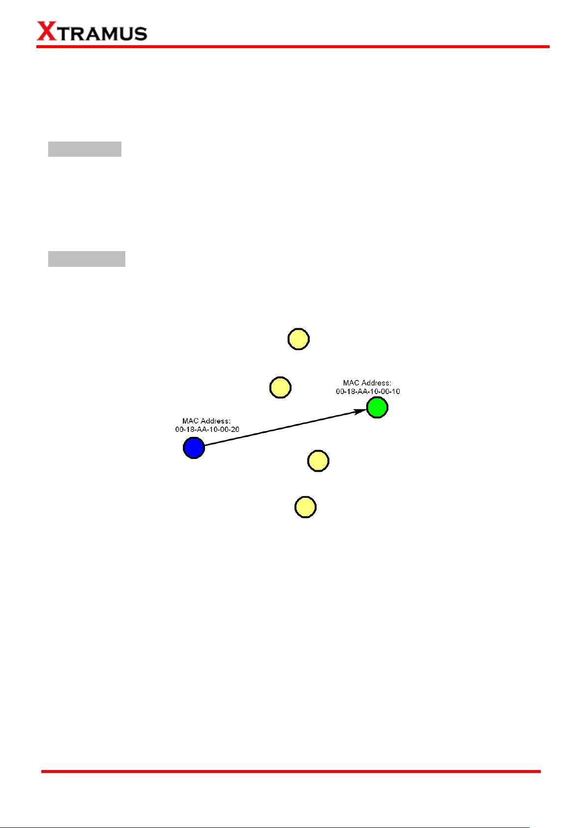
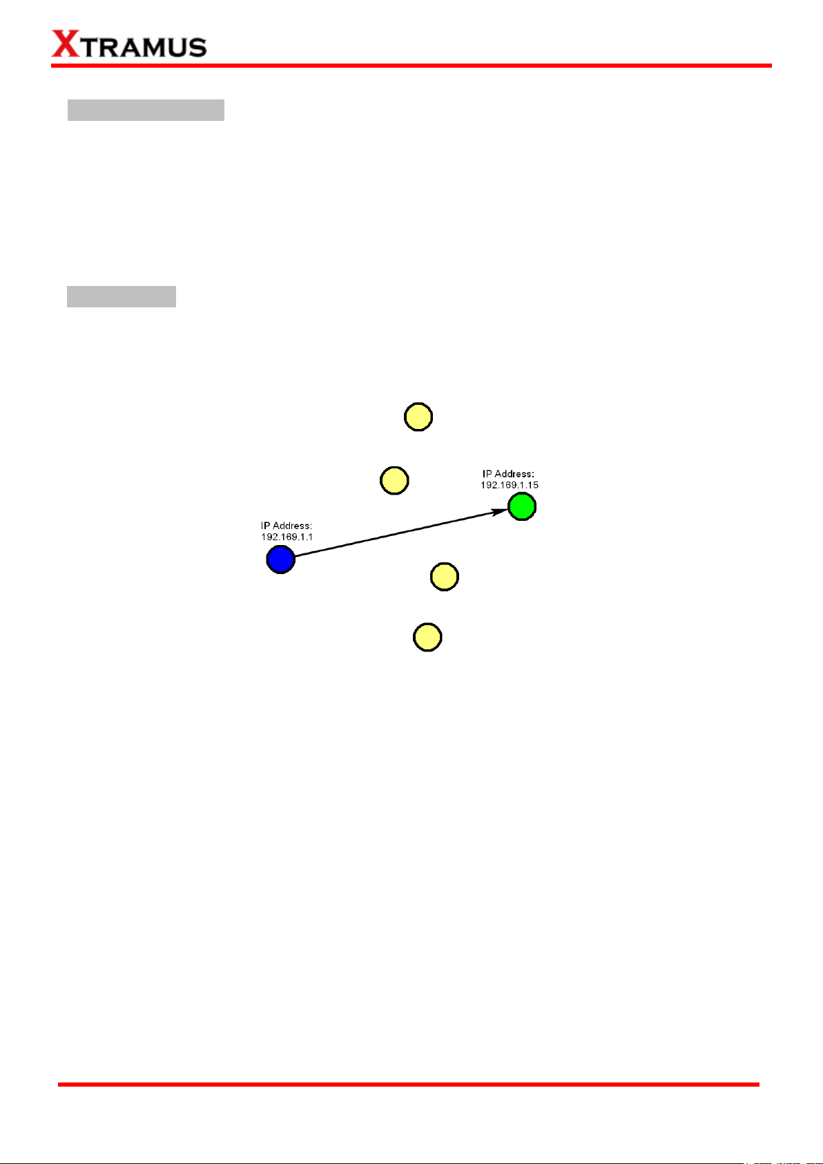
A. Unicast Test
Unicast transmission is to send information packets to a single destination. In layer 2 test, unique MAC
address is the key of single destination as illustration below.
Perform unicast test on DUT in layer2 with different speeds, modes and various configurations.
PT2-UC-10H (10Mbps Half Duplex),
PT2-UC-10F (10Mbps Full Duplex),
PT2-UC-100H (100Mbps Half Duplex),
PT2-UC-100F (10Mbps Full Duplex),
PT2-UC-1G (1Gbps Full Duplex),
PT2-UC-10G (10G Full Duplex),
PT2-UC-GROUPS (Perform Layer 2 MAC address Unicast performance test by two groups
settings with different media types such as 100Mbps and 1Gbps for DUT ports with different
maximum speeds)
Page 8
8
E-mail: sales@xtramus.com
Website: www.Xtramus.com
XTRAMUS TECHNOLOGIES®
B. Flow Control Test
Perform flow control test on DUT in layer 2 with different speeds, modes and various configurations. It
tests the performance when the DUT is connected to the media type with varied kinds of speeds and
directions.
PT2-FC-10H-100H (10Mbps Half ↔ 100Mbps Half),
PT2-FC-100H-10H (100Mbps Half ↔10Mbps Half),
PT2-FC-10F-100F (10Mbps Full ↔ 100Mbps Full),
PT2-FC-100F-10F (100Mbps Full ↔ 10Mbps Full),
PT2-FC-100F-1G (100Mbps Full ↔ 1Gbps Full),
PT2-FC-1G-100F (1Gbps Full ↔ 100Mbps Full),
PT2-FC-1G-10G (1Gbps Full ↔ 10G Full),
PT2-FC-10G-1G (10G Full ↔ 1Gbps Full),
PT2-FC-GROUPS (Perform Layer 2 Flow Control tests by two groups with different media types
such as 100Mbps and 1Gbps for DUT ports with different maximum speeds.)
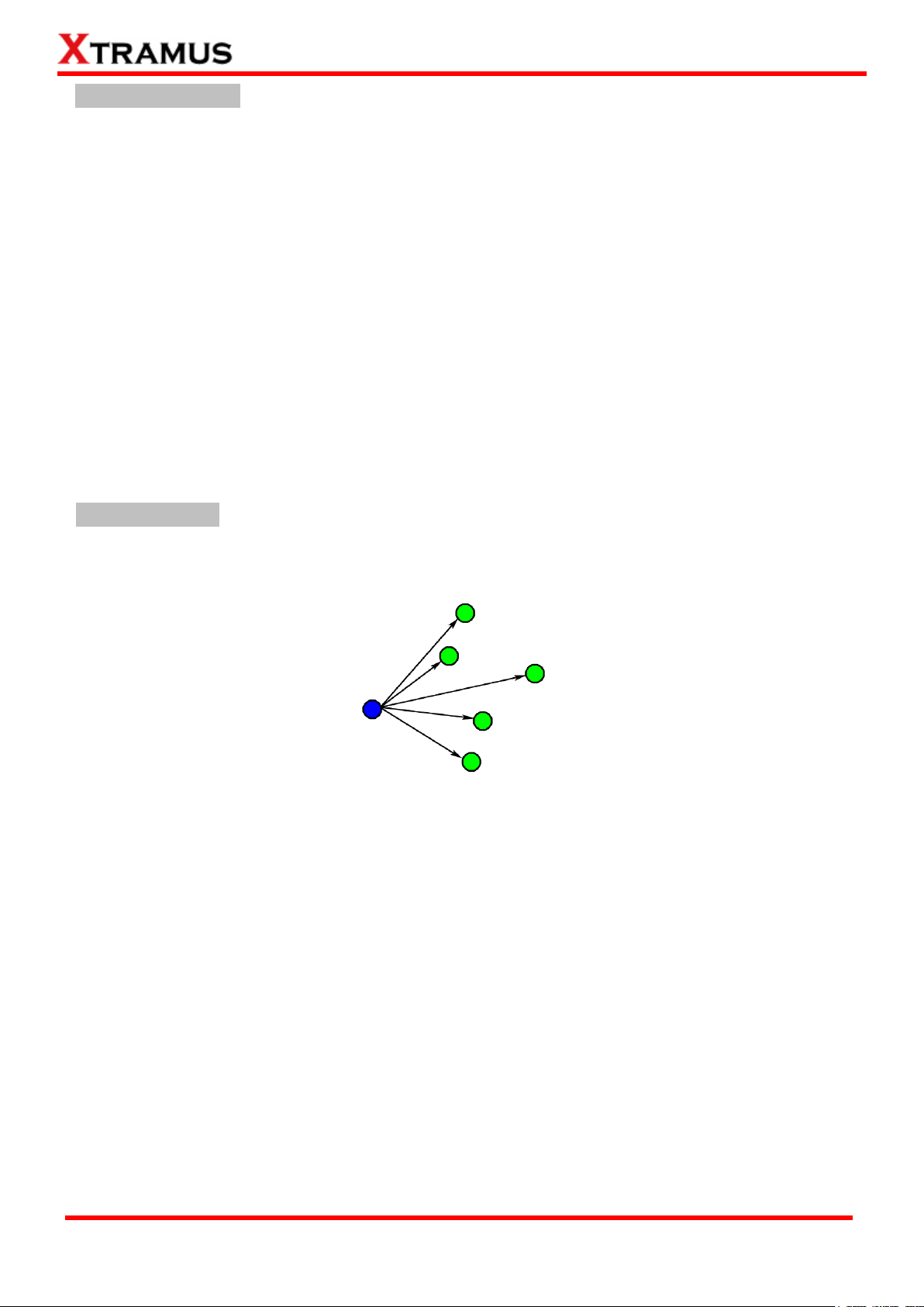
C. Broadcast Test
Broadcasting refers to transmitting packets that will be received (conceptually) by every device on the
network.
Perform broadcast test on DUT in layer2 with different speeds, modes and various configurations.
These following tasks transmit broadcast frames (Destination Address: FF:FF:FF:FF:FF:FF).
PT2-BC-10H, (10Mbps, Half Duplex)
PT2-BC-10F, (10Mbps, Full Duplex)
PT2-BC-100H, (100Mbps, Half Duplex)
PT2-BC-100F, (100Mbps, Full Duplex)
PT2-BC-1G, (1Gbps, Full Duplex)
PT2-BC-10G, (10Gbps, Full Duplex)
PT2-BC-GROUPS (Perform Layer 2 Broadcast test by two groups with different media types such
as 100Mbps and 1Gbps for DUT ports with different maximum speeds.)
Page 9
9
E-mail: sales@xtramus.com
Website: www.Xtramus.com
XTRAMUS TECHNOLOGIES®
D. Filter Test
This filter test should filter all packets with the same source MAC address and destination MAC Address.
For the test packets transmitted are all with the same source MAC address and destination MAC
address and the DUT should filter this kind of packet.
Perform filter test on DUT in layer2 with different speeds, modes and various configurations. The
following tasks transmit frames with same DA (destination address) and SA (source address).
PT2-FT-10H, (10Mbps, Half Duplex)
PT2-FT-10F, (10Mbps, Full Duplex)
PT2-FT-100H, (100Mbps, Half Duplex)
PT2-FT-100F, (100Mbps, Full Duplex)
PT2-FT-1G, (1Gbps, Full Duplex)
PT2-FT-10G, (10Gbps, Full Duplex)
PT2-FT_GROUPS (Perform Layer 2 Filter Test by two groups with different media types such as
100Mbps and 1Gbps for DUT ports with different maximum speeds.)
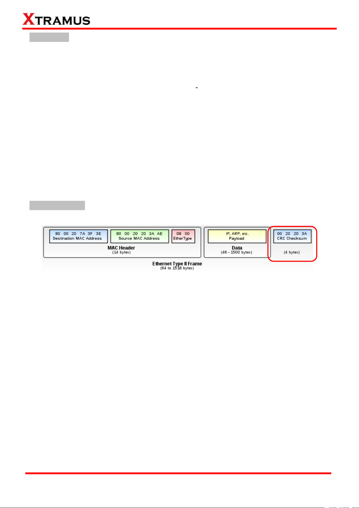
E. CRC Error Test
CRC Checksum is registered at the end of Ethernet frame.
Perform CRC (Cyclic Redundancy Check) error test on DUT in layer2 with different speeds, modes and
various configurations for the last 4 bytes of CRC to be filtered. For normal DUT, frame with error CRC
should be filtered. The following tasks transmit frames with CRC errors.
PT2-CRC-10H, (10Mbps, Half Duplex)
PT2-CRC-10F, (10Mbps, Full Duplex)
PT2-CRC-100H, (100Mbps, Half Duplex)
PT2-CRC-100F, (100Mbps, Full Duplex)
PT2-CRC-1G, (1Gbps, Full Duplex)
PT2-CRC-10G, (10Gbps, Full Duplex)
PT2-CRC-GROUPS (Perform Layer 2 CRC check test by two groups with different media types
such as 100Mbps and 1Gbps for DUT ports with different maximum speeds.)
Page 10
10
E-mail: sales@xtramus.com
Website: www.Xtramus.com
XTRAMUS TECHNOLOGIES®
1.3.3. Performance Tasks in Layer 3 (PT3) A. Network Tool: Ping
Ping is a network tool used to test whether a particular host is reachable across an IP network. It is also
used to self-test the network interface card of the computer, or as a speed test.
Perform Ping test on DUT in layer3 that is based on different IP addresses, subnet mask, ping IP address
and gateway.
PT3-Ping
B. Unicast Test
Unicast transmission is to send information packets to a single destination. In layer 3 test, unique IP
address is the key of single destination as illustration below.
Perform unicast test on DUT in layer 3 with different speeds, mode and various configurations.
PT3-UC-10H, (10Mbps, Half Duplex)
PT3-UC-10F, (10Mbps, Full Duplex)
PT3-UC-100H, (100Mbps, Half Duplex)
PT3-UC-100F, (100Mbps, Full Duplex)
PT3-UC-1G, (1Gbps, Full Duplex)
PT3-UC-10G, (10Gbps, Full Duplex)
PT3-UC-GROUPS (Layer 3 Unicast Full Performance Test. Perform Layer 3 IP Address Unicast
test by two groups with different media types such as 100Mbps and 1Gbps for DUT ports with
different maximum speeds.)
Page 11

11
E-mail: sales@xtramus.com
Website: www.Xtramus.com
XTRAMUS TECHNOLOGIES®
1.3.4. PoE (Power over Ethernet) Test
Overview of PoE
PoE: Power Over Ethernet
Based on IEEE 802.3af and ongoing 802.3at
Protocol for DTE power via copper-based media
DTE (Data Terminal Equipment)
PSE: Power Sourcing Equipment
Equipment provides the power to PD by network cable.
PD: Powered Device
Device consumes the power from PSE by network cable. NuStream-2000i, 600i with PoE module
acts as PD for the test.
A. PoE-Connect
Perform connect test on DUT (i.e. PSE) based on different configurations.
B. PoE-Disconnect
Perform disconnect test on DUT (i.e. PSE) based on different configurations.
C. PoE-Overload
Perform overload test on DUT (i.e. PSE) based on different configurations.
D. PoE-ShortCircuit
Perform short circuit test on DUT (i.e. PSE) based on different configurations.
E. PoE-Loading
Perform loading and transmitting packets test on DUT (i.e. PSE) based on different configurations.
F. PoE-Loading-GROUPS
Perform loading and transmitting packets test on DUT (i.e. PSE) based on different configurations and
criteria for two groups with different media types such as 100Mbps and 1Gbps
G. POE-Dynamic Loading
Perform multiple loading and transmitting packets test on DUT (i.e. PSE) in different configurations at the
same time.
Page 12

12
E-mail: sales@xtramus.com
Website: www.Xtramus.com
XTRAMUS TECHNOLOGIES®
1.3.5. AC Test
A. PWR-Setup
Perform power control on DUT such as power ON control and cycle reboot through test module XM-2WL1.
Under the control of XM-2WL1 module on chassis, the DUT that use the power from XM-2WL1 can have
ON / OFF and reboot control.
B. PWR-Check
Perform power monitor and statistics measurement from power plug into test module XM-2WL1. The outlet
of XM-2WL1 also supply power to DUT, thus operator gets the power statistics measurement to DUT.
1.3.6. Terminal Test
This test includes two parts: Console and Telnet test. Perform test by executing commands by manual
script or script file to RS232 interface or Telnet Server of DUT.
A. Console
Console refers to the console port, COM port or RS232 interface. This test will perform a series of standard
terminal command to check the response of COM port.
B. Telnet
Perform test by executing commands by manual script file to Telnet Server of DUT.
1.3.7. General Test Tests listed in this category include: 1 to Many-UC, 1 to Many-MCV,CALL-EXT, Inserting Waiting Time,
Media Pre-setting ,Toggle MDI-II/X and Line Emulate .
A. 1 to Many-UC
1 to Many-UC is a Unicast Full Performance Test. Performing Layer 2 MAC address Unicast performance
tests from one source to multiple ports with different media types (such as 100Mbps and 1Gbps Full).
Page 13

13
E-mail: sales@xtramus.com
Website: www.Xtramus.com
XTRAMUS TECHNOLOGIES®
B. 1 to Many-MCV
Performing Layer 2 VLAN address multicast performance tests from one source port to multiple
destination ports with different media types (such as 100Mbps and 1Gbps Full).
C. CALL-EXT
This function allows you to execute your own programs/files as APMPT-4 Tasks.
D. Inserting Waiting Time
This function allows users to insert waiting time in-between tasks or to pause the whole testing process
after completing a task.
E. Media Pre-Setting
Test MDIX by Media Pre-setting mode or force MDI (straight-through connection) or MDIX (crossover
connection) mode of DUT.
F.Toggle MDI-II/X
Test the Auto MDIX function of different speeds/link modes of the DUT. Toggle MDI-II/X is a technology
that automatically detects the required cable connection type (straight-through or crossover) and
configures the connection appropriately.
G. Line Emulate
This function allows you to set the device 5160 or other line simulators connecting to the DUT port. Line
Emulate task must be performed ahead of the task which needs it.
1.3.8. Customization Test
A. CTM-BSTAR-001
This function allows two ports to co-transmit packets in which both side can have different Tx
parameters.
Page 14
14
E-mail: sales@xtramus.com
Website: www.Xtramus.com
XTRAMUS TECHNOLOGIES®
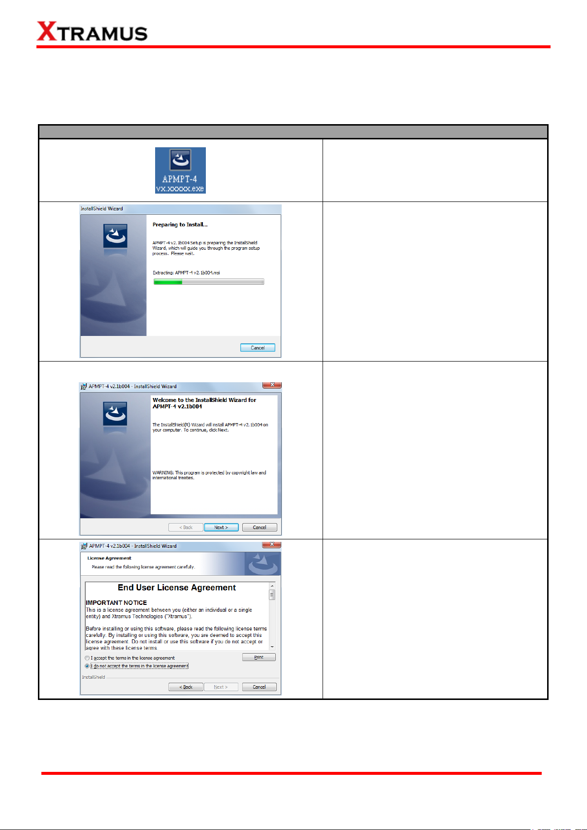
1. Double-click APMPT-4 installation program
and start the installation process.
2. InstallShield Wizard is starting to install
APMPT-4. If you would like to cancel
installation, click Cancel.
3. Click Next to continue installation.
4. Click I accept the terms in the license
agreement, and click Next to continue.
2. Software/Hardware Installation for APMPT-4
2.1. Install/Uninstall APMPT-4 on PC
Please follow the steps down below to install APMPT-4:
Page 15
15
E-mail: sales@xtramus.com
Website: www.Xtramus.com
XTRAMUS TECHNOLOGIES®
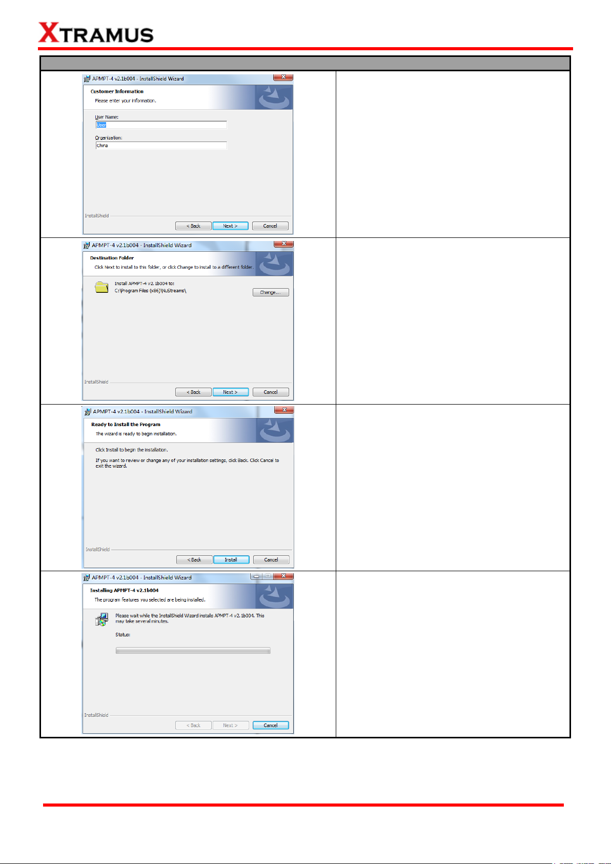
5. Input the User Name and Organization and
click Next to continue.
6. Click the Change… button to install the
program to another folder, or click Next button
to install the program into the default
destination folder, and then continue next step.
Click Back button to go back to the previous
step to modify.
7. Click Install to begin the installation.
8. InstallShield Wizard is installing APMPT-4.
Page 16
16
E-mail: sales@xtramus.com
Website: www.Xtramus.com
XTRAMUS TECHNOLOGIES®
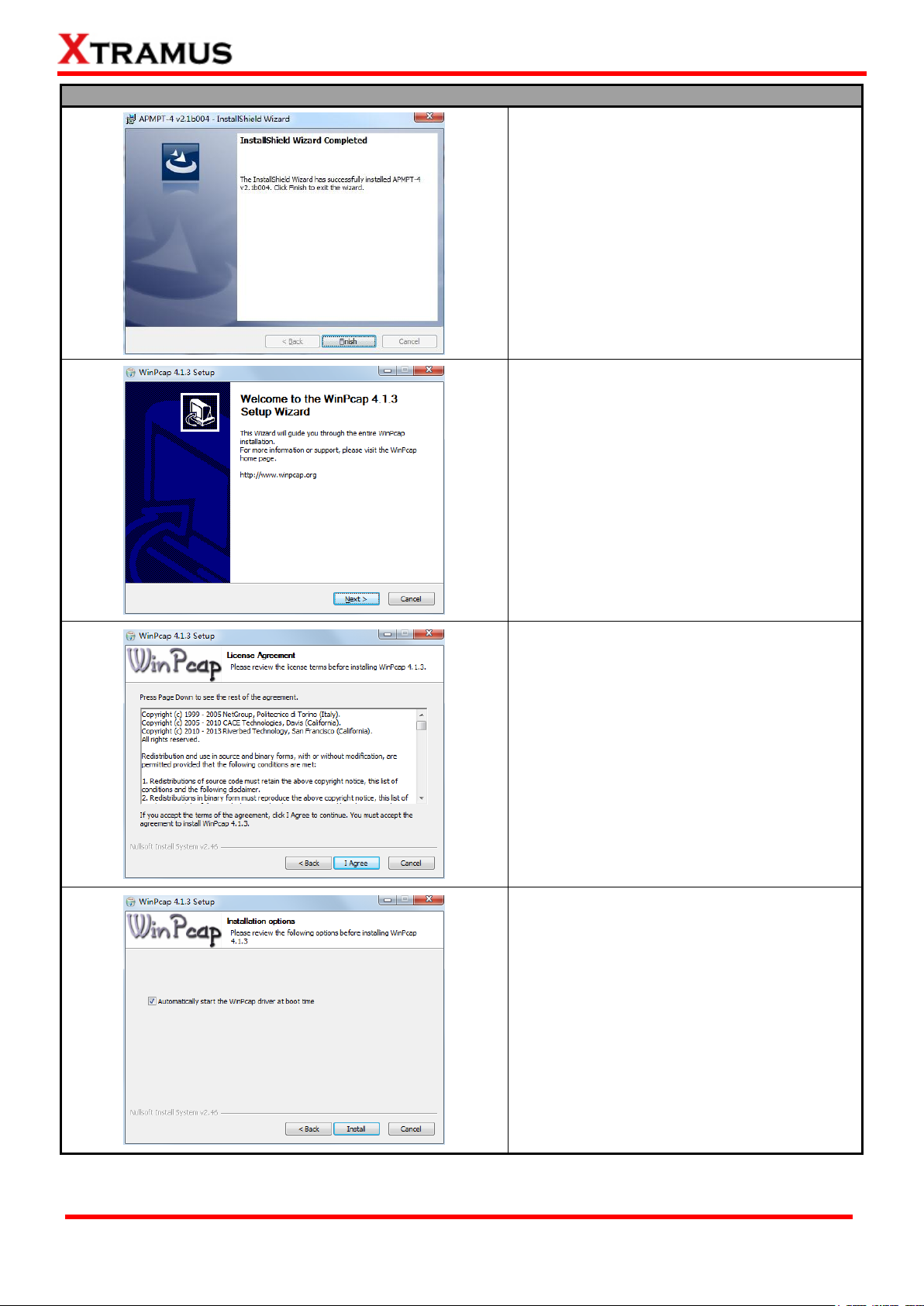
9. Click Finish to exit the wizard.
10. WinPcap Installer appears. Click Next
button to get ready to install, or click Cancel
button to stop.
11. Review the license agreement before
installing. Click I Agree button to continue. It is
necessary to accept the agreement to install
WinPcap.
12. It is high recommended to check the
“Automatically start the Wincap driver at boot
time” as default. Then click Install.
Page 17
17
E-mail: sales@xtramus.com
Website: www.Xtramus.com
XTRAMUS TECHNOLOGIES®
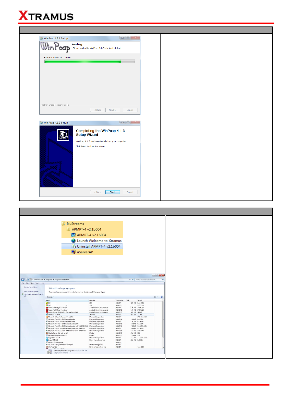
13. WinPcap is installing.
14. WinPcap installation completes. Click
Finish button to close the wizard.
You can uninstall APMPT-4 by:
Click Start → Programs → NuStreams →
APMPT-4→ Uninstall APMPT-4
Go to the Control Panel, choose
APMPT-4 from installed program list, and
click “Uninstall”.
Page 18
18
E-mail: sales@xtramus.com
Website: www.Xtramus.com
XTRAMUS TECHNOLOGIES®
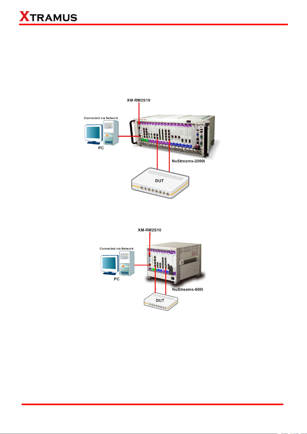
2.2. Hardware Installation
Before running APMPT-4 after installation, please be sure that you‟ve installed both the DUT and your PC
with Nustreams-2000i/600i properly as shown in the illustrations down below.
For operating APMPT-4 on NuStreams-2000i and NuStreams-600i Chassis, an external PC is required.
For NuStreams-2000i, connect network port of PC LAN card to DOWN (or UP) port of XM-2S19 with
network cable.
For NuStreams-600i, connect network port of PC LAN card to DOWN (or UP) port of XM-2S10 with
network cable.
Please note that the PC‟s TCP/IP setting should be configured so that the PC‟s NIC will obtain an IP
address from NuStreams-2000i/600i automatically.
Page 19
19
E-mail: sales@xtramus.com
Website: www.Xtramus.com
XTRAMUS TECHNOLOGIES®
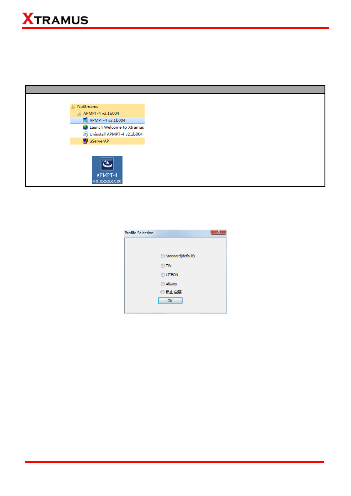
You can start running APMPT-4 by:
Click Start Programs NuStreams
APMPT-4.
Double-click APMPT-4 icon located on your
PC‟s desktop.
3. APMPT-4 Overview
3.1. Starting APMPT-4
Before starting APMPT-4, the DUT, your PC, and NuStreams-2000i/600i shall be connected as shown in
“2.2. Hardware Installation”.
When you first start the APMPT-4, a Profile Section window as below will pop up. Select standard
(default) option in general case. If you are a user of a certain customized company, select the
corresponding option.
If your PC is not connected with NuStreams-2000i/600i, you can still run APMPT-4 under Demo Mode.
Almost all APMPT-4‟s functions are available under Demo Mode. However, please note that Demo Mode
is for system demo purposes only, and does not serve any test purpose at all.
Page 20
20
E-mail: sales@xtramus.com
Website: www.Xtramus.com
XTRAMUS TECHNOLOGIES®
Page 21
21
E-mail: sales@xtramus.com
Website: www.Xtramus.com
XTRAMUS TECHNOLOGIES®
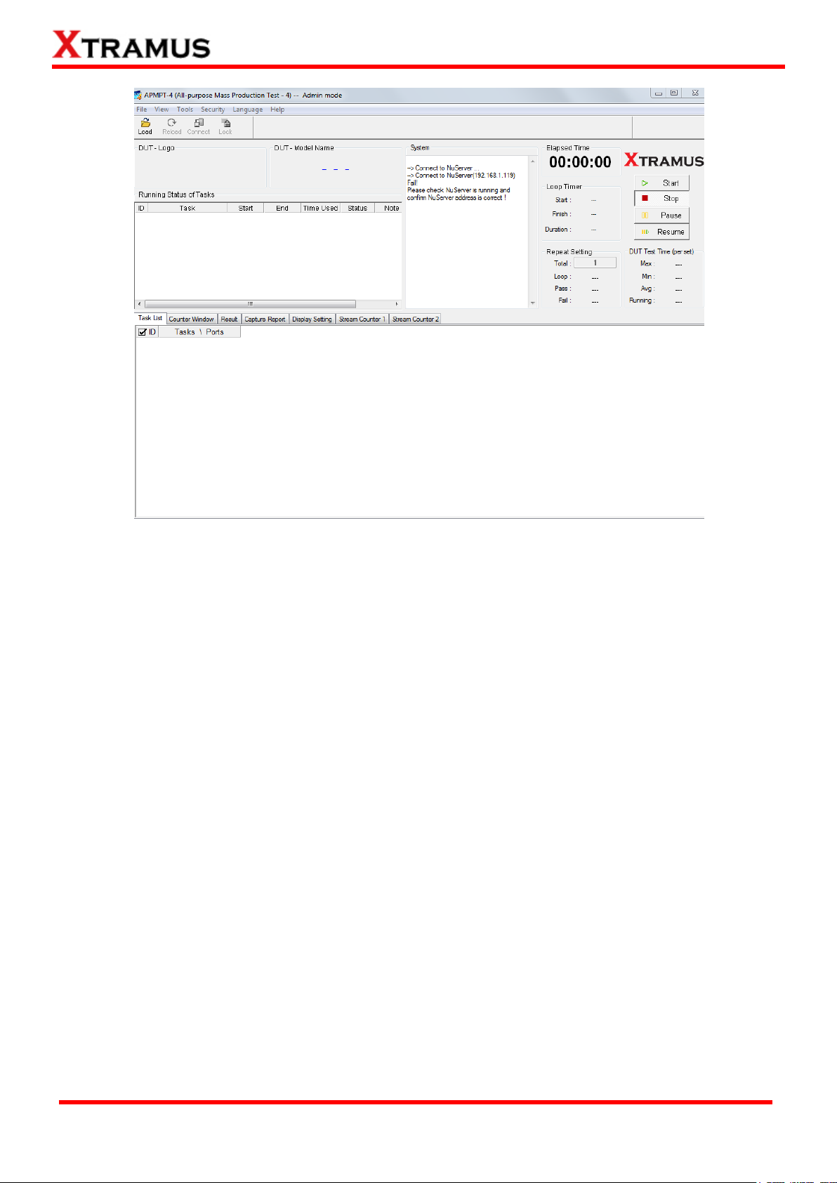
Please follow the steps down below to start APMPT-4:
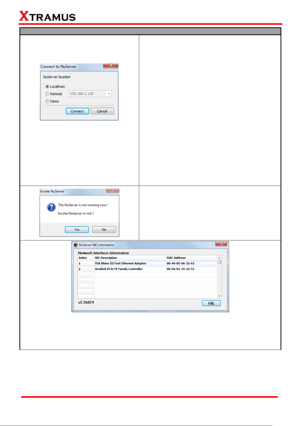
When starting APMPT-4, a “Connect to NuServer”
window will pop up and asked how you are going to
connect to NuServer.
Local Host: Choose this option when you‟re
running APMPT-4 from NuStreams-2000i IPC
module or a PC that‟s connected to
NuStreams-2000i/600i via an RJ45 cable.
Remote: Choose this option when you‟re running
APMPT-4 from other PC located on the network.
Choose the IP address which is assigned from
NuStreams-2000i/600i from the scroll-down menu。
Demo: Choose demo to enter APMPT-4‟s Demo
Mode.
Connect/Cancel: Click the Connect button to
connect to NuStreams-2000i/600i or click the
Cancel button to quit.
If NuServer is not running while starting APMPT-4, a
window will pop up and ask if you would like to run
NuServer. Please click Yes to continue or No to cancel.
A “NuServer-NIC Information” window will pop up. Please select the NIC (Network Interface Card) which is
connected to NuStreams -2000i/ 600i from the Network Interface Information table, and click OK. If you‟re
using NuStreams-2000i‟s IPC module, please choose “Realtek RTL8139 Family Fast Ethernet”. NuServer
will connect to the daughter boards, and APMPT-4 will start as well.
Page 22
22
E-mail: sales@xtramus.com
Website: www.Xtramus.com
XTRAMUS TECHNOLOGIES®
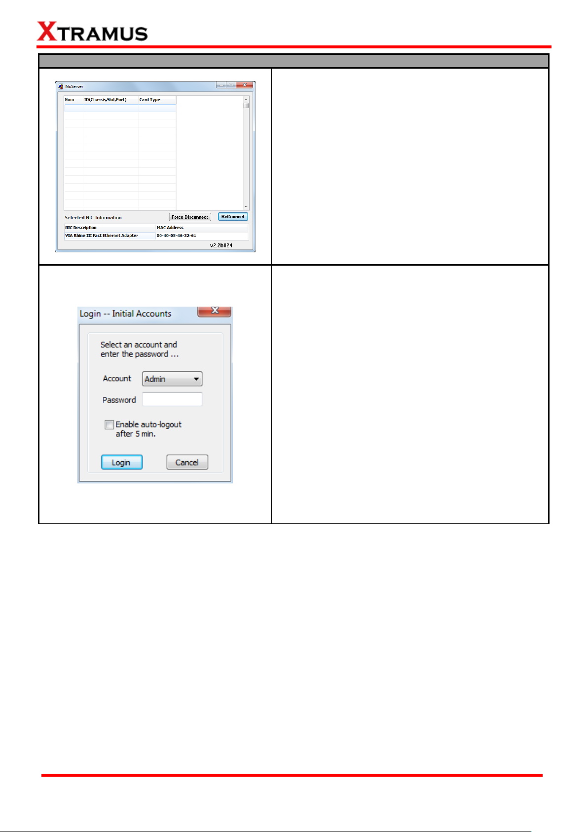
Please follow the steps down below to start APMPT-4:
When the information listed in the Nuserver window is
abnormal, click Force Disconnect, and then click
ReConnect.
Force Disconnect: Disconnect with NuStreams -2000i/
600i forcefully.
ReConnect: Reconect with NuStreams -2000i/ 600i.
For security reasons, APMPT-4 requires
Account/Password to login. The default
Account/Password is:
Account: Admin
Password: xtramustech
Please note that the password is case-sensitive, and
shall be changed as soon as you login for the first time.
Please refer to “3.3.4. Security” for more information
about how to change APMPT-4‟s password.
Enable auto-logout after 5 min: Enable this
function so APMPT-4 shall automatically logout
after 5 minutes.
Login/Cancel: Click Login/Cancel button to login
or cancel.
Page 23
23
E-mail: sales@xtramus.com
Website: www.Xtramus.com
XTRAMUS TECHNOLOGIES®
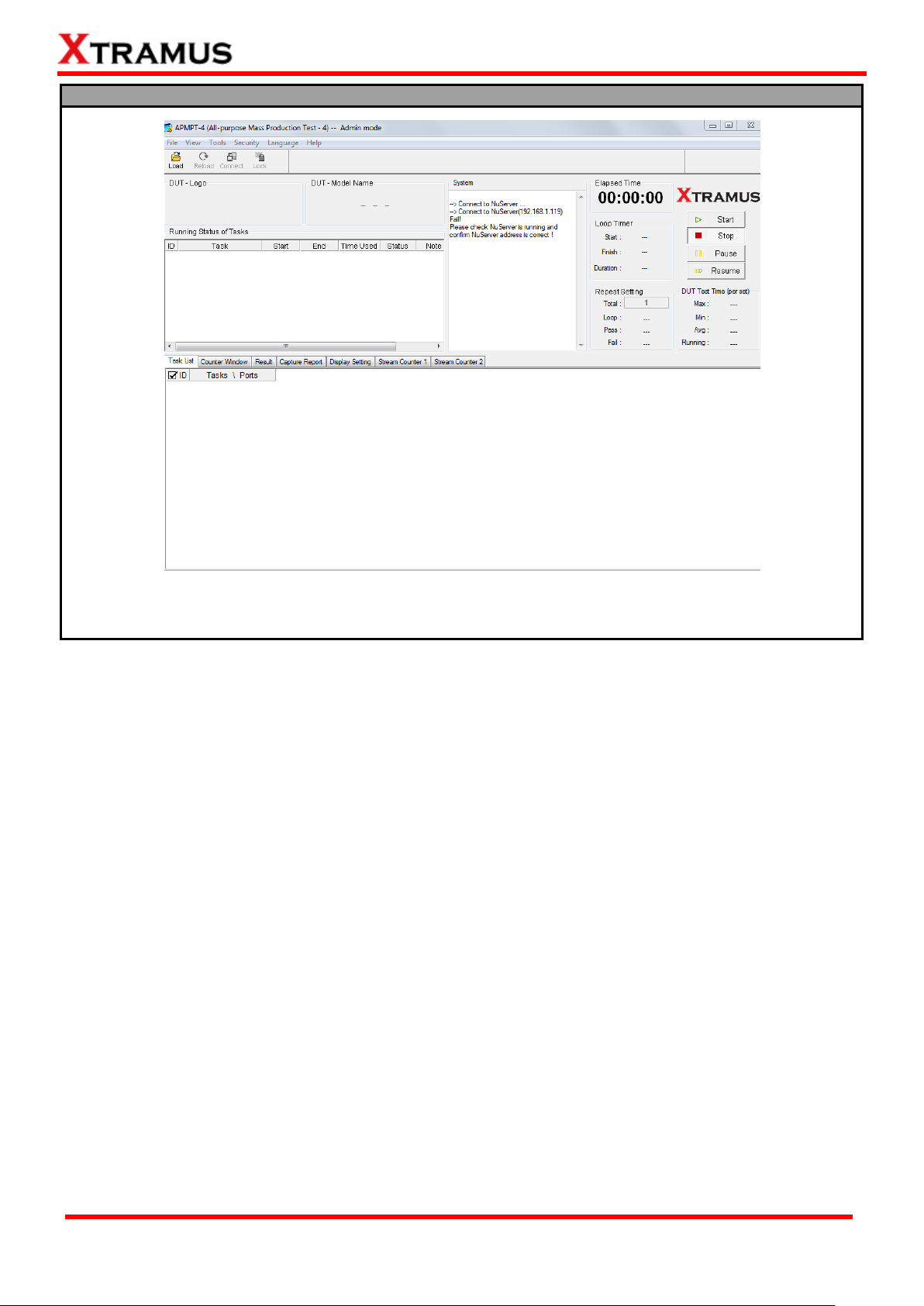
Please follow the steps down below to start APMPT-4:
You now have access to APMPT-4‟s main display window.
Page 24
24
E-mail: sales@xtramus.com
Website: www.Xtramus.com
XTRAMUS TECHNOLOGIES®
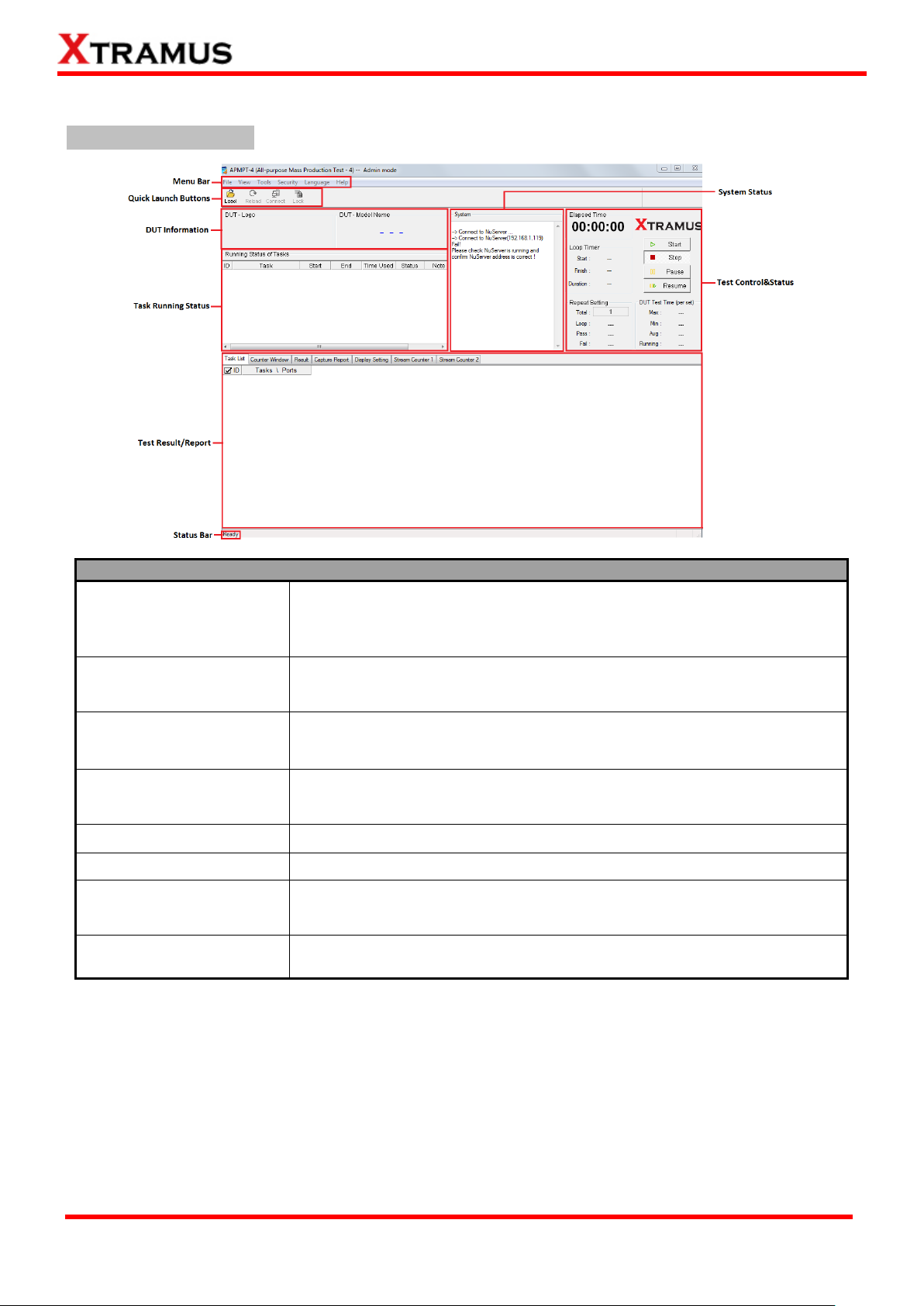
Function Descriptions
Menu Bar
The Menu Bar allows you to manage test model settings, view test log/
model information, set/reset APMPT-4 password, and change language
displayed.
Quick Launch Buttons
The Quick Launch Buttons allow you to load/reload test model settings,
connect to the NuServer, and lock test model.
DUT Information
This section of the main window contains the DUT„s logo and model
name.
Task Running Status
This section of the main window contains general information/status of the
tasks that are currently running.
Status Bar
The Status Bar shows the APMPT-4‟s running status.
System Status
The System Status displays running processes of APMPT-4 system.
Test Control & Status
The Test Control & Status section contains test control buttons (which
allow you to Start/Stop/Pause/Resume tests) and general test information.
Test Result/Report
This section allows you to view the test results.
3.2. APMPT-4/NuServer Main Window Overview
APMPT-4 Main Window
Page 25
25
E-mail: sales@xtramus.com
Website: www.Xtramus.com
XTRAMUS TECHNOLOGIES®
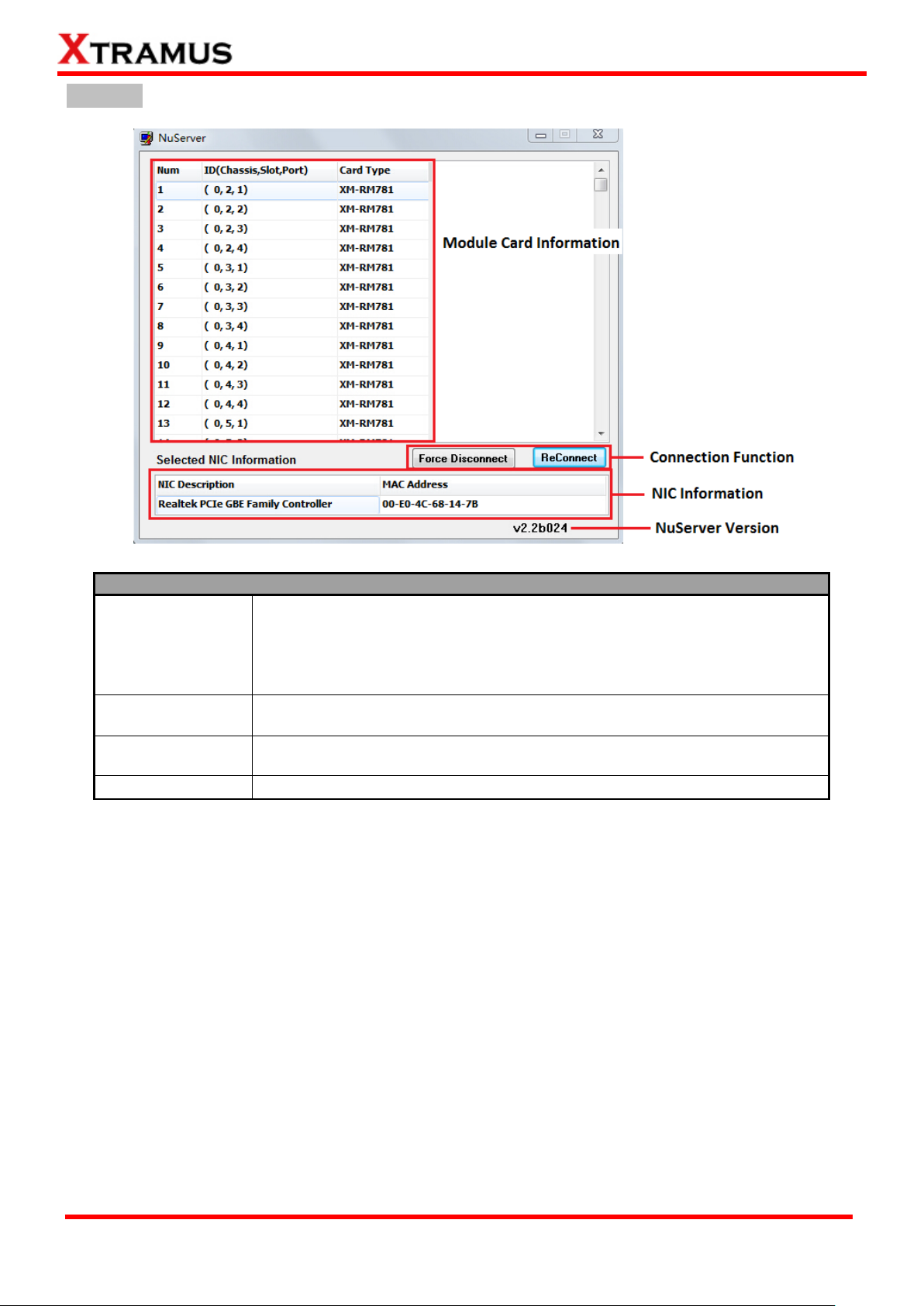
Description
Module Card
Information
This section displays the information regarding to the model cards that are
installed on NuStreams-2000i/600i. Model Card IDs are showed as the
format of (X, Y, Z) while X is the number of the chassis (which is displayed
on NuStreams-2000i/600i), Y is the slot number where this model card is
installed, and Z is the available port number located on the model card.
Connection
Function
You can reconnect a link down status or force to disconnect your
NuStreams-600i/2000i to your PC.
NIC Information
This section displays the detail information (including NIC Model name,
NIC‟s MAC address) regarding to the selected NIC.
NuServer Version
This section displays the version of your NuServer.
NuServer
Page 26
26
E-mail: sales@xtramus.com
Website: www.Xtramus.com
XTRAMUS TECHNOLOGIES®
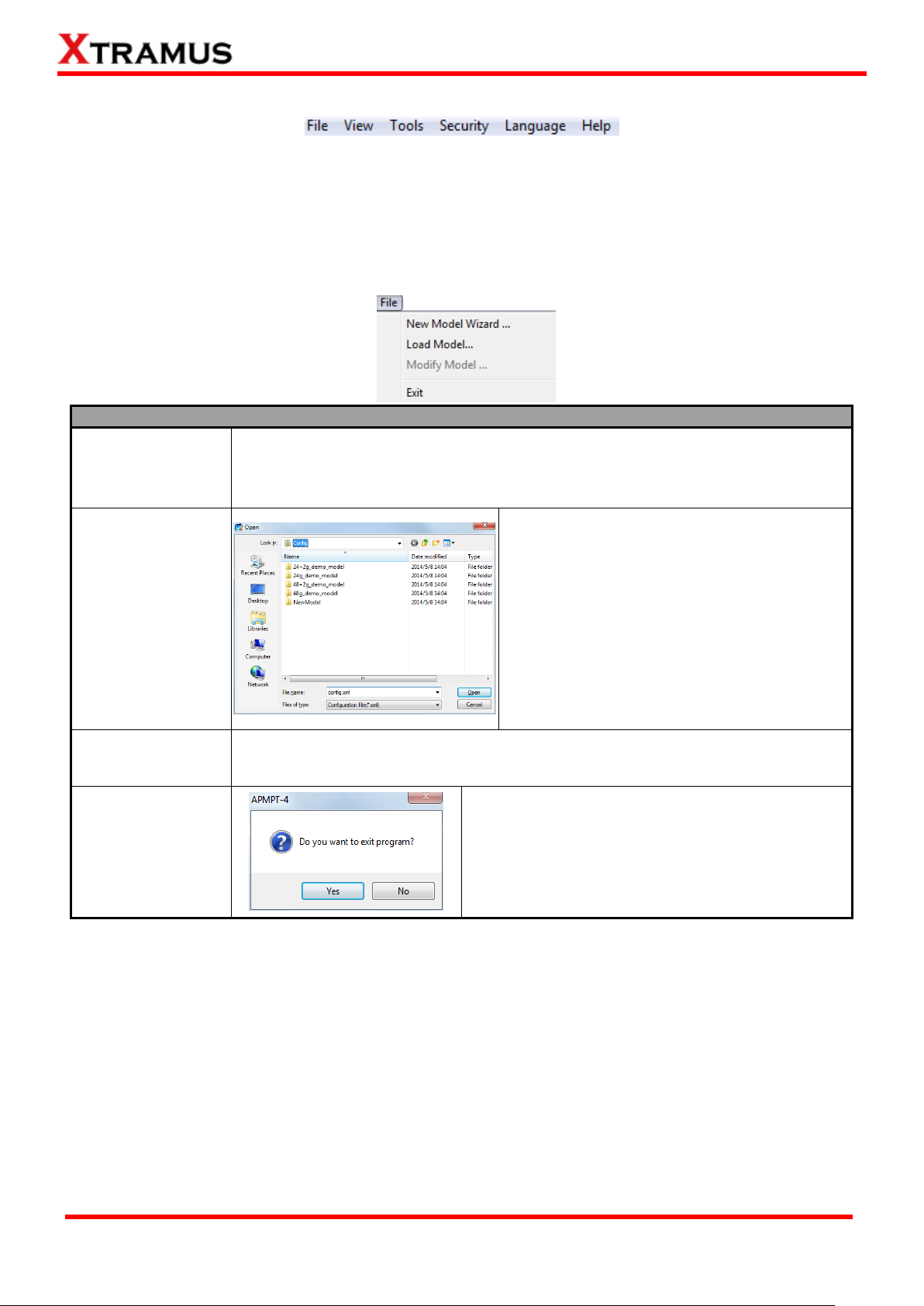
File Menu Bar Overview
New Model Wizard
Choose this option to start the New Model Wizard. The New Model Wizard allows
the users to set testing options for DUT. For detail descriptions regarding to the
New Model Wizard and its settings, please refer to”4. Creating Task via New
Model Wizard”.
Load Model
Load a previously-saved configuration file and
apply these settings to APMPT-4.
All the configurations you‟ve made via New
Model Wizard will be saved as a “*.xml” file,
along with several “*.cfg” files.
Please note that these “*.cfg” files contain test
settings as well. Deleting them will cause your
“*.xml” file unable to load properly.
Modify Model
Choose this option to make changes to the current test settings for DUT. For detail
descriptions regarding to these settings, please refer to the section down below.
Exit
A prompt pop-up window will ask if you are sure to
exit APMPT-4. Click Yes to exit APMPT-4, or click
No to cancel.
3.3. Menu Bar
APMPT-4 Menu Bar includes configuration options such as File, View, Tools, Security, Language, and
Help. Please refer to the sections down below for detail information regarding to each configuration
option.
3.3.1. File
Page 27

27
E-mail: sales@xtramus.com
Website: www.Xtramus.com
XTRAMUS TECHNOLOGIES®
View
Latest Log
Choose Latest Log allows you to view the latest test log file (in “*.txt” format).
Log Folder
Choose Log Folder, and then the folder where all the saved test logs of the current test
model will be opened.
Model Folder
Choose Model Folder, and then the folder where all the DUT model configuration files are
saved will be opened. The default Log folder file path is under “C:\Program
Files\NuStreams\APMPT-4 v2.1b004\config”.
Module
Information
The Module Information window displays all the module cards that are installed on
NuStreams-2000i/600i and their detail information. To close the Module Information
window, click OK button.
NuServer
Display the NuServer window. For more information regarding to NuServer window,
please refer to “3.2. APMPT-4/NuServer Main Window Overview”.
Simple Style
Choose Simple Style will make you run the tests under a simple mode.
3.3.2. View
Page 28
28
E-mail: sales@xtramus.com
Website: www.Xtramus.com
XTRAMUS TECHNOLOGIES®
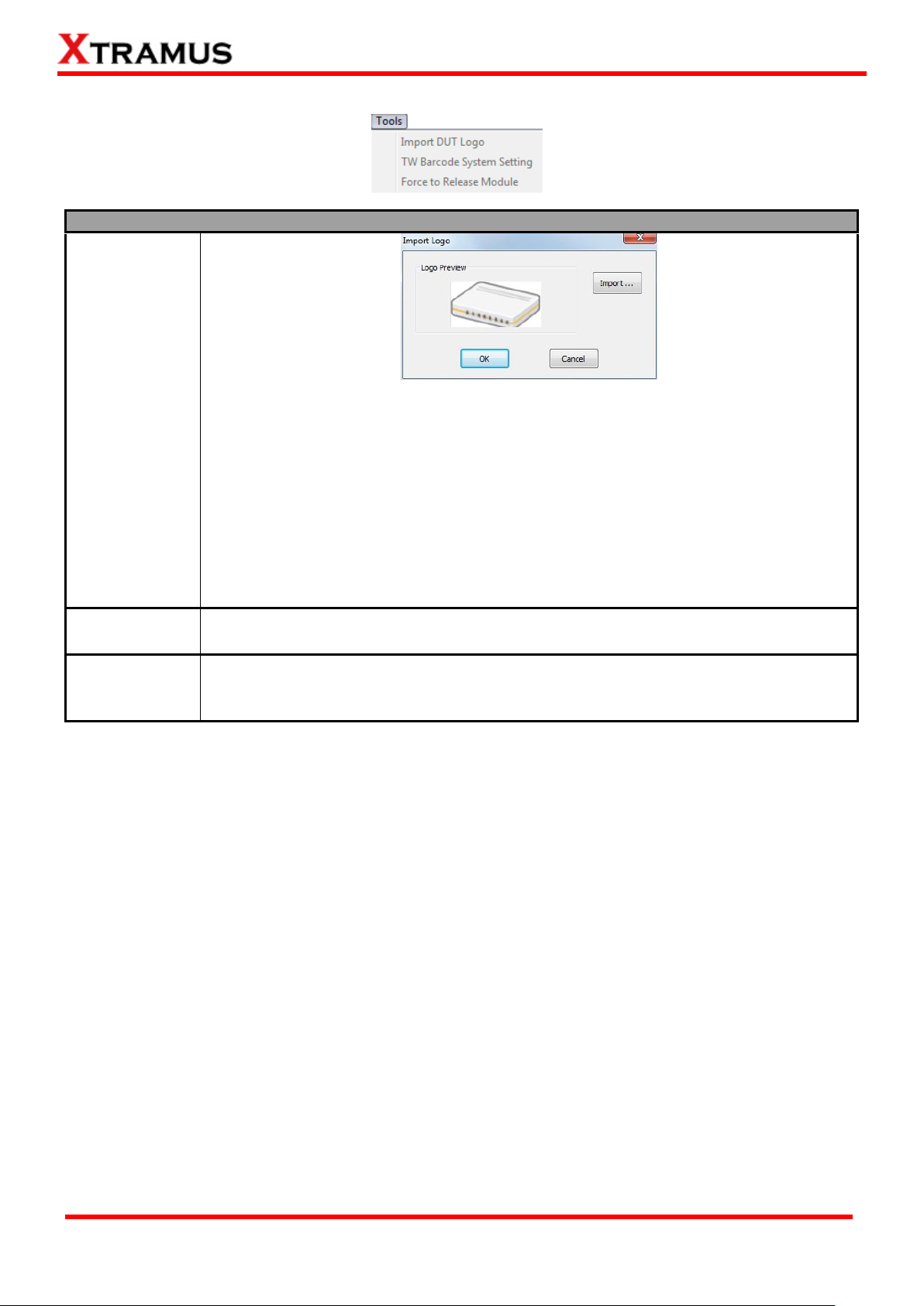
Tools
Import DUT
Logo
You can load an image file that represents the DUT for testing via Import DUT Logo
function. The image file you chose will be shown on DUT Logo field of the Main
Window.
Logo Preview: The image you‟ve chosen will be displayed in this field for
preview.
Import: Click this button to choose the image file that will be displayed.
OK: Click this button to apply the changes you‟ve made.
Cancel: Click this button to abandon all the changes you‟ve made and exit
Import Logo Window.
TW Barcode
System Setting
The Setting is for TW Barcode System
Force to
Release Module
When the test encounters some unexpected problems which lead the board dead, or
other tests need to lock the current board, you can choose Force to Release Module
to obtain the board again.
3.3.3. Tools
Page 29
29
E-mail: sales@xtramus.com
Website: www.Xtramus.com
XTRAMUS TECHNOLOGIES®
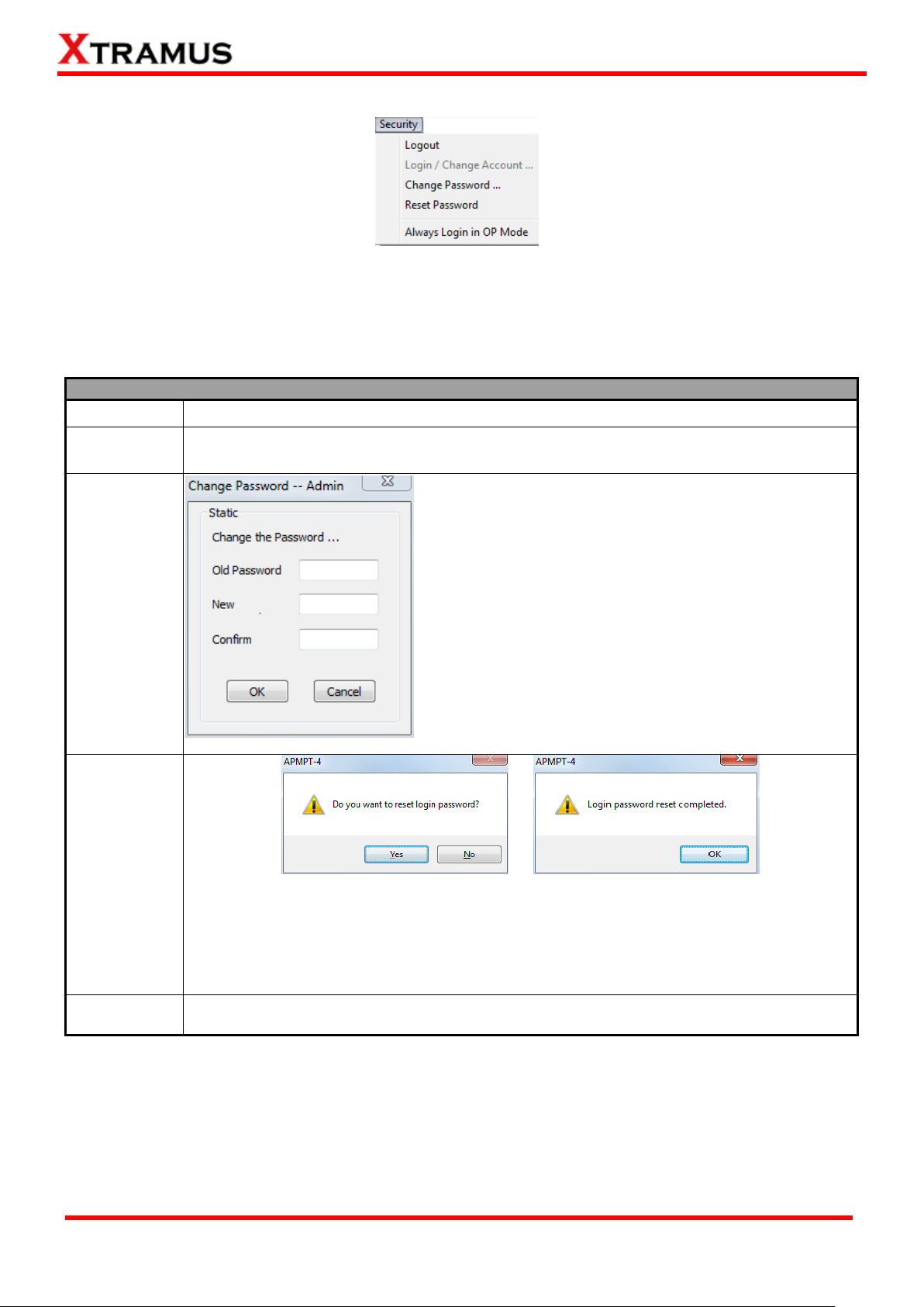
Security
Logout
Logout from Admin Mode and switch APMPT-4 to Operator Mode.
Login/Change
Account
Login to the Admin Mode.
Change
Password
You can change the password for Admin Mode here.
For security reasons, it is recommended to change
APMPT-4‟s password after you first login.
Old Password: Enter the old password here.
New: Enter the new password here. The new
password should be 6~12 characters and
mustn‟t contain special symbols.
Confirm: Please type your new password again
for confirming.
OK: Apply all the changes you‟ve made and
apply.
Cancel: Cancel and abandon all the changes
you‟ve made.
Reset
Password
If you forget APMPT-4‟s Admin Mode password, you can reset the password to the
default password “xtramustech”.
Click Yes to start resetting the login password (or No to cancel), and click OK to
complete.
Always login
in OP Mode
Every time when APMPT-4 starts running, it will run under Operator Mode.
3.3.4. Security
APMPT-4 can run under Admin Mode and Operator Mode:
Admin Mode: Users have the maximum authorization and can access all APMPT-4‟s functions.
Operator Mode: Users are only allowed to access APMPT-4‟s basic functions such as loading
saved DUT model test settings and view latest test log/module card information/NuServer
Page 30
30
E-mail: sales@xtramus.com
Website: www.Xtramus.com
XTRAMUS TECHNOLOGIES®
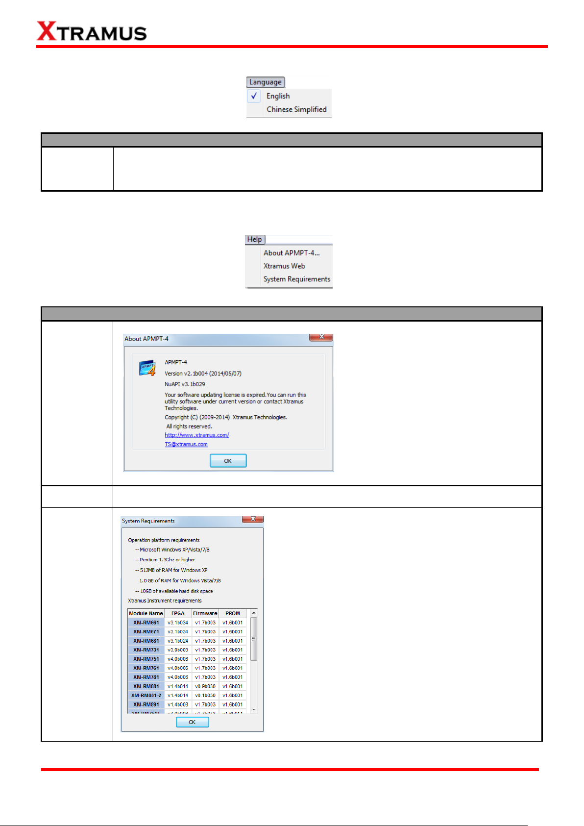
Language
English/
Chinese
Simplified
APMPT-4 has 2 different languages for its UI available. You can set the language of UI to
either English or Simplified Chinese.
Help
About
APMPT-4
The About APMPT-4 window will pop up
and show detailed system information.
Xtramus Web
Click this option to access to Xtramus official website.
System
Requirement
The “System Requirements” window will pop up and
show the requirements for your PC and the
FPGA/Firmware/PROM version limit of the module
cards. Click the Ok button to exit the “System
Requirements” pop up window.
3.3.5. Language
3.3.6. Help
Page 31

31
E-mail: sales@xtramus.com
Website: www.Xtramus.com
XTRAMUS TECHNOLOGIES®
Quick Launch Buttons
The Load Quick Launch Button
serves the same function as Load
Model on the Menu Bar.
Clicking this button allows loading a
previously-saved configuration file and
applies these settings to APMPT-4.
All the configurations you‟ve made via
New Model Wizard will be saved as a
“*.xml” file, along with several “*.cfg”
files.
Please note that these “*.cfg” files
contain test settings as well. Deleting
them will cause your “*.xml” file unable to load properly.
APMPT-4 will reload the current opened DUT model setting and apply all these settings.
The Connect button allows you to re-connect to the NuServer if it is not connected while
initializing APMPT-4.
Clicking the Lock button allows the user to lock a specific module card installed on a
NuStreams-600i/2000i chassis.
3.4. Quick Launch Buttons
The Quick Launch Buttons allow you to Load/Reload DUT Model Settings, Connect to NuServer, or Lock
a Module Card on the Chassis.
Page 32

32
E-mail: sales@xtramus.com
Website: www.Xtramus.com
XTRAMUS TECHNOLOGIES®
DUT Information
DUT – Logo
You can load an image file that represents the DUT from your PC, and apply it as DUT Logo for reference via Import DUT Logo function located on the Menu Bar. The image
file you chose will be shown here.
DUT –
Model Name
When making configurations in New Model Wizard, you can input a model name under
Model Name field. For detailed information, please refer to “4.1. Selecting Active Ports
from Installed Module Cards”. The model name you input will be shown here.
3.5. DUT Information
The DUT Information on APMPT-4 Main Window displays the DUT‟s Logo and Model Name.
Page 33

33
E-mail: sales@xtramus.com
Website: www.Xtramus.com
XTRAMUS TECHNOLOGIES®
Description
ID
Task ID. Tests will be performed
Task
Name of the Task.
Start
The start time of the task.
End
The end time of the task.
Time Used
Display time used with the task.
Status
Task Pass/Fail/Done.
Note
Notes regarding to the task.
3.6. Task Running Status
The Task Running Status displays general information/status of the tasks that are currently running. The
Task Running Status is blank if no DUT Model Setting is loaded to APMPT-4.
3.7. Status Bar
The Status Bar located on the bottom-left of APMPT-4 Main Window shows the task APMPT-4 is
currently running and its progress.
3.8. System Status
The System Status shows detailed information of APMPT-4‟s system status and what APMPT-4 is
currently processing.
3.9. Test Control & Status
Page 34

34
E-mail: sales@xtramus.com
Website: www.Xtramus.com
XTRAMUS TECHNOLOGIES®
Loop Timer
Start/Finish
This section displays the starting/finishing time (including date) of the test.
Duration
This section displays the maximum duration of time spent on one single loop.
Repeat Setting
Total
You can set the how many times you would like to repeat all the tests here in this field.
Loop
This section displays the current number of test loop.
Pass/Fail
This section displays how many times the tests have been passed/failed.
Elapsed Time
Elapsed Time
This section displays duration of time spent on the whole testing process.
Task Control Buttons
The Task Control Buttons allow you to control the testing process.
Start: Click this button to start DUT test.
Stop: Click this button to stop DUT test. If you click Start button again afterwards,
DUT test will start from the beginning.
Pause: Click this button to pause DUT test. This DUT test can be resumed later on.
Resume: Click this button to resume a previously paused DUT test.
DUT Test Time (per set)
Max/Min
Maximum/Minimum period of time used when performing one set of tasks.
Avg
The average period of time used when performing one set of tasks.
Running
The total time used to perform the tasks.
The Test Control & Status allows user to control testing process via control buttons and view general
information regarding to test time.
Page 35

35
E-mail: sales@xtramus.com
Website: www.Xtramus.com
XTRAMUS TECHNOLOGIES®
4. Creating Task via New Model Wizard
When performing tests on your DUT with APMPT-4 for the first time, you have to create a new set of test
settings for the DUT.
Before starting to create a new task via New Model Wizard, please be sure that:
All module cards (such as XM-RM751, XM-RM761, or XM-RM781) are installed on chassis (such as
NuStreams-2000i/600i) properly.
The chassis (such as NuStreams-2000i/600i) is powered-on and is connected to a PC according to “2.2.
Hardware Installation”.
To start using New Model Wizard, please click File on the Menu Bar, and choose New Model Wizard as
shown in the figure down below.
A “New Model Wizard – Active Ports for Selection!” window will pop up. All module cards that are
installed on the chassis will be displayed here.
Please refer to the sections down below and start creating test tasks for your DUT.
Page 36

36
E-mail: sales@xtramus.com
Website: www.Xtramus.com
XTRAMUS TECHNOLOGIES®
A. Tree Style Tab Buttons
These two buttons allow you to unfold/fold all the Active Port tree style tab displayed in B.
These two buttons allow you to check/uncheck all the Active Port displayed in B.
4.1. Selecting Active Ports from Installed Module Cards
Page 37

37
E-mail: sales@xtramus.com
Website: www.Xtramus.com
XTRAMUS TECHNOLOGIES®
B. Active Port Tree Style Tab & E. Module Card List
All the module cards, along with their Active Ports are listed here in this field.
You can fold/unfold the tree style tab by clicking / icons. Also, you can
check/uncheck the port by clicking icon.
Also, you can check which module card and its Active Ports are activated for
tests in E. Module Card List as well. Click the check box in front the module
card you would like to activate/deactivate.
C. DUT Model Name & Active Port Count
You can input DUT‟s model name here in this field.
Please note that a folder named after the model name you input here will
be created under “config” folder inside APMPT-4‟s folder (Default path:
C:\Program Files\NuStreams\APMPT-4 v0.9b060\config), and all the
configuration files and test logs will be saved to that folder.
This field display how many ports you‟ve been activated for now.
D. Auto Start
If you would like APMPT-4 to start the test automatically (with delay in a
few seconds) without having to press the Start button located on the Main
Window, check the check-box here and input the delay time in the field
down below.
F. Next>/Cancel
Click this button to apply all the changes you‟ve made and move on to the New Model
Wizard - The Ports of New Model -- Preview and Confirm! window.
Click this button to abandon all the changes you‟ve made and go back to the Main
Window.
Page 38

38
E-mail: sales@xtramus.com
Website: www.Xtramus.com
XTRAMUS TECHNOLOGIES®
After finishing the module cards/Active Ports for the
tests, you can review all the ports, module cards,
and model name on New Model Wizard - The
Ports of New Model -- Preview and Confirm!
window.
Click Next > to start making detail task settings or
click < Back to go back to Select Active Ports
window.
Also, you can click Cancel to abandon all the
changes you‟ve made and go back to the Main
Window.
Page 39

39
E-mail: sales@xtramus.com
Website: www.Xtramus.com
XTRAMUS TECHNOLOGIES®
4.2. Making Settings on Option – New Model Window
An Option – New Model window will show up after you‟ve selected module cards and Active Ports. The
Option – New Model window allows you to make detail test configurations.
APMPT-4 has two different kinds of configurations: Environment Setting and Task List Setting.
Environment Setting: Configure global settings of the test environment for all tasks.
Task List Setting: All test tasks are listed and categorized by groups. All tasks added to the Selected
Tasks field will be listed under this category and can be configured in detail.
For more detail information and descriptions regarding to these settings, please refer to the sections
down below.
Page 40

40
E-mail: sales@xtramus.com
Website: www.Xtramus.com
XTRAMUS TECHNOLOGIES®
4.2.1. Configuring Environment Setting
To access Environment Setting and start configuring global settings of the test environment for all
tasks, please click Environment from the Configuration Tree Style Tab located on the left side of
Option – New Model window as shown in the figure above.
Please note that all changes you‟ve made here will be kept temporally and won‟t be lost if you switch to
Task List Setting. However, you must click Save or Save as (located on the bottom-right part of the
Option – New Model window to apply all the changes you‟ve made.
Page 41

41
E-mail: sales@xtramus.com
Website: www.Xtramus.com
XTRAMUS TECHNOLOGIES®
A. DUT – Port Number
You can view the number of active ports in this field.
B. DUT – Logo Setup
You can load an image file that represents the DUT from your PC, and apply it
as DUT - Logo for reference by clicking the Import button. The image file you
chose will be shown on the DUT – Logo field located on Main Window.
C. Model Name
You can input or change DUT‟s model name here in this field.
Please note that a folder named after the model name you input here will be
created under “config” folder inside APMPT-4‟s folder (Default path:
C:\Program Files\NuStreams\APMPT-4 v2.1boo4\config), and all the
configuration files and test logs will be saved to that folder.
Page 42
42
E-mail: sales@xtramus.com
Website: www.Xtramus.com
XTRAMUS TECHNOLOGIES®
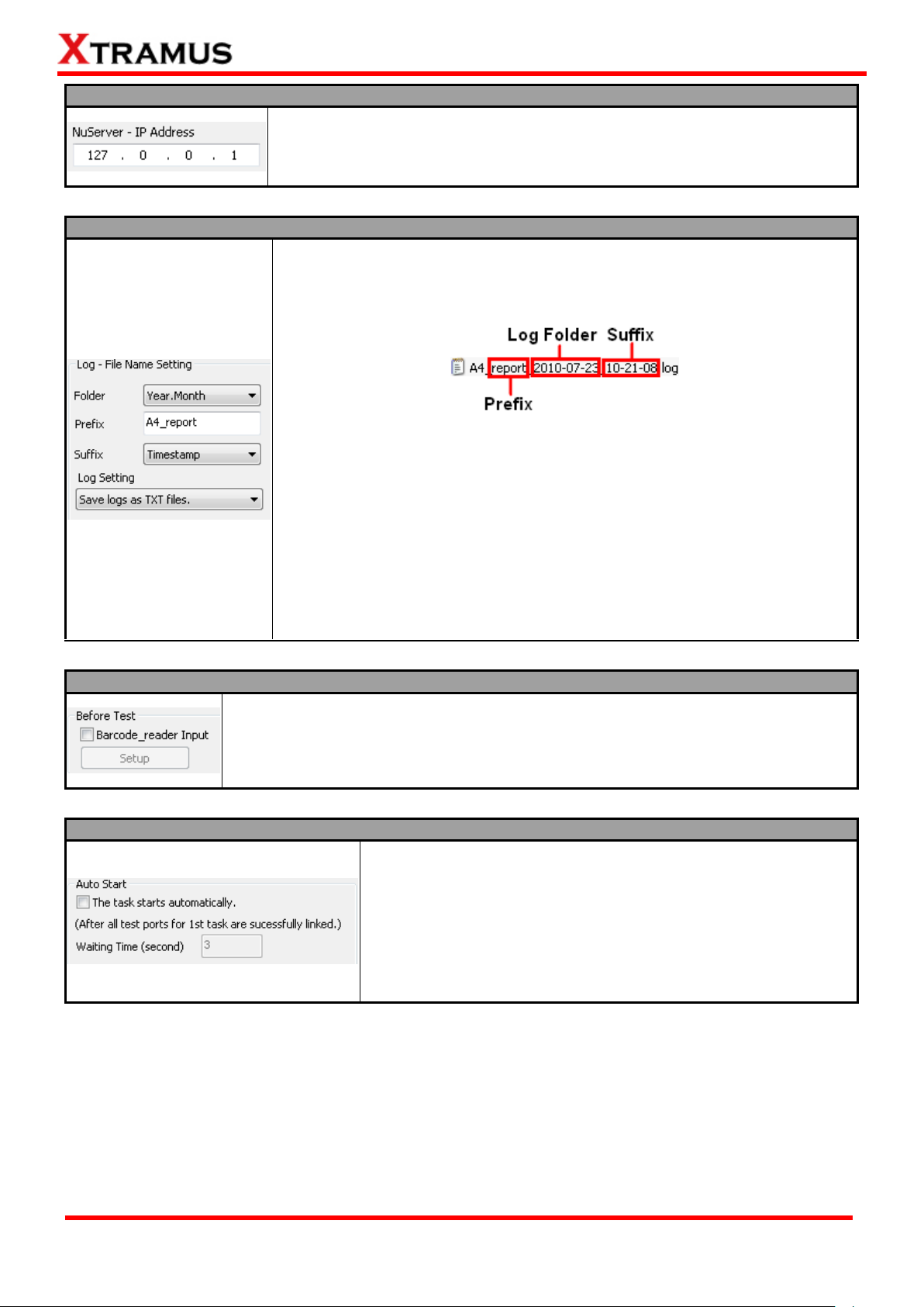
D. NuServer – IP Address
If you‟re running APMPT-4 from other PC located on the network, you can set
the IP address which is assigned from NuStreams-2000i/600i from the
scroll-down menu or input the IP address manually.
E. Log – File Name Setting
Test results will be saved as log files and named automatically after tests are
completed. All log files‟ names are consisted in the format as shown in the
figure down below:
APMPT-4 creates test result logs and stores these logs automatically to
folders named after the testing date. You can set the names that will be
applied to these folders and test result logs here in Log – File Name Setting.
Folder: You can set the name of the log folders as “Year, Month”, or
“Year, Month, Day”.
Prefix: You can input the prefix word for test result log names here.
Suffix: You can set the suffix as Timestamp (the log file creating time),
Serial Number, and Bar Code (barcode).
Log Setting: In this field, you can choose the format of your test result
report. The report format can be TXT, XML or both TXT and XML .
F. Barcode Reader
By connecting a barcode reader to your PC, you can scan pre-defined barcodes
with the barcode reader. Information such as DUT Task Settings, Operator ID and
DUT MAC Address can be read by barcode reader and input into APMPT-4.
G. Auto Start
APMPT-4 will halt and wait for further instructions after the current
running task is completed. You can click the check- box in this
section so that APMPT-4 will start the next task automatically.
Also, you can set how many seconds shall APMPT-4 be waiting
before starting the next task in the field down below (Waiting
Time).
Page 43

43
E-mail: sales@xtramus.com
Website: www.Xtramus.com
XTRAMUS TECHNOLOGIES®
H. Port Alias Setup
You can set alias for all Activated Ports here in Port Alias Setup window. Alias you
input here will be shown in the Main Window.
Page 44

44
E-mail: sales@xtramus.com
Website: www.Xtramus.com
XTRAMUS TECHNOLOGIES®
I. Log Folder Path
As mentioned in “E. Log – File Name Setting”, APMPT-4
creates test result logs and stores these logs automatically to
designated folders.
You can set where you want to save the test logs by the
scroll-down menu.
Default Log Folder: Test logs will be saved to the default
log folder, which is: C:\APMPT-4.log\APMPT-4
v2.1b004\Model Name\log.
DUT’s Model Folder: Test logs will be saved to where DUT
test settings are saved.
User Defined Folder: Test logs will be saved to the
designated file path you input in the Path field down below.
Export to PDF report: Selecting this option will allow you to
export the log in PDF format.
J. PPS Rate Factor
Set the rate factor of packet per seconds.
K. The MAX number of reset
Set the max number of times to repeat the test.
L. Others
Final Report Window: It includes Default, Pass
only and Fail only options, in which Default will show
all the test result, Pass only will only show the passed
test and Fail only will only show the failed test.
Upload Data to MES: If you enable the Upload Data
to MES function, the Database Setup button will be
available. Clicking the Database Setup button will
pop up a Database Setup window for settings.
The Database Setup window allows you to set your
Driver Type and allows you to define your User ID,
Password, Server Name, Database Name and
Table Name.
Besides, you can also Set Number of Item (up to 20
items) to be displayed and click Apply button to
confirm. You can scroll down each Source Data‟s field
to indicate it as Work Area, SN1, OP_ID,
Time_Start, Time_End, Time_Used, Model_Name,
DUT_MAC or Final_Result.
Page 45

45
E-mail: sales@xtramus.com
Website: www.Xtramus.com
XTRAMUS TECHNOLOGIES®
4.2.2. Adding/Removing Tasks via Task List Setting
Under Task List Setting, you can:
View all APMPT-4‟s available tasks according to their groups.
Add/Delete task that you would like to perform.
Arrange order of the tasks.
To start managing tasks for your DUT, please click List of Selected Tasks on the left side of the
Option – New Model.
Page 46

46
E-mail: sales@xtramus.com
Website: www.Xtramus.com
XTRAMUS TECHNOLOGIES®
A. Task Add/Remove Buttons
The Task Add/Remove Buttons allow you to add or remove tasks to/from Selected
Tasks.
By clicking button, you can add the task you‟ve selected from Built-in Tasks field
in the left-side to the Selected Tasks in the right-side.
By clicking button, you can remove the task you‟ve selected from the Selected
Tasks in the right-side.
Page 47

47
E-mail: sales@xtramus.com
Website: www.Xtramus.com
XTRAMUS TECHNOLOGIES®
B. Built-in Tasks & C. Task Group Selection
The Built-in Tasks display tasks available in APMPT-4. You can choose
which tasks you would like the system to display on Built-in Tasks field with
the Task Group Selection scroll-down menu.
All: Display all tasks available.
Test Tasks – Layer 1: Display all available Layer 1 tasks.
Test Tasks – Layer 2: Display all available Layer 2 tasks.
Test Tasks – Layer 3: Display all available Layer 3 tasks.
Test Tasks – PoE: Display all available PoE (Power over Ethernet) tasks.
Test Tasks – AC: Display all available AC (Power) tasks.
Test Tasks – Terminal: Display all available Terminal tasks.
Test Tasks – General: Display all available general tasks.
Test Tasks – Customization: Display all available Customization tasks.
To add a task to Selected Tasks, please click the task you would like add in
Built-in Tasks, and click button.
Page 48

48
E-mail: sales@xtramus.com
Website: www.Xtramus.com
XTRAMUS TECHNOLOGIES®
D & F. Selected Tasks
All tasks you‟ve selected from Built-in Tasks field will be listed in the Select
Tasks. The number of the tasks you chose will be shown here as well.
To remove a task from Selected Tasks, please click the task you would like to
remove here, and click button.
E. Selected Tasks Managing Buttons
You can manage the testing order of tasks listed in the Selected Tasks.
To move the priority of a task listed in Selected Tasks up, click on that task, and click
button; to move the priority of a task listed in Selected Tasks down, click on that task, and
click button.
If you would like to remove all the tasks listed in Selected Tasks, click button.
Page 49

49
E-mail: sales@xtramus.com
Website: www.Xtramus.com
XTRAMUS TECHNOLOGIES®
4.2.3. Configuring Tasks Listed on List of Selected Tasks After choosing the tasks you would like to perform from Built-in Tasks as mentioned in “4.2.2. Task List Setting”, you can start making detail settings with individual tasks by clicking the task you would like to
configure from List of Selected Tasks. All the configurations for this task will be listed in the right-side
section as shown in the figure down below.
Please note that the maximum number of tasks that can be selected into the List of Selected Tasks is
32.
As mentioned in “4.2.2. Task List Setting, B. Built-in Tasks & C. Task Group Selection”, all tasks
available for APMPT-4 can be divided into different groups Layer 1, Layer 2, Layer 3, PoE (Power over
Ethernet), AC (DUT Power Test), Terminal, General and Customization.
For more detailed information regarding to task settings in APMPT-4‟s task groups, please refer to “5.
APMPT-4 Detail Task Setting.”
You can use the three buttons to save the settings.
Save: Click this button, a “Save As” window as below will pop up and prompt you to save all the
configurations you made.‟
Page 50

50
E-mail: sales@xtramus.com
Website: www.Xtramus.com
XTRAMUS TECHNOLOGIES®
Save As: Click this button, a “Save As” window will pop up and you can save your configurations into
another file.
Cancel: Click this button, a reminder window as below will pop up. Click OK to exit the Option – New
Model window. Or click Cancel to return to the Option – New Model window.
The default name for the configuration setting is “config” and will be saved in a folder named after the
DUT‟s Model Name. All configuration setting files are saved as XML format, and changing configuration
setting‟s file type may cause APMPT-4 unable to load your previous saved setting file. APMPT-4 will
apply all the settings you‟ve made after saving.
Page 51

51
E-mail: sales@xtramus.com
Website: www.Xtramus.com
XTRAMUS TECHNOLOGIES®
5. APMPT-4 Detail Task Setting
As mentioned in “4.2.3. Configuring Tasks Listed on List of Selected Tasks”, you can make detail
settings with individual tasks by clicking the task you would like to configure from List of Selected Tasks.
All the configurations for this task will be listed in the right-side section as shown in the figure down below.
All tasks available for APMPT-4 can be divided into different groups Layer 1, Layer 2, Layer 3, PoE
(Power over Ethernet), AC (DUT Power Test), Terminal, General and Customization. Please refer to
“1.3. Function Description” for detail descriptions. Also, descriptions for each task can be viewed on
APMPT-4 as well.
Page 52

52
E-mail: sales@xtramus.com
Website: www.Xtramus.com
XTRAMUS TECHNOLOGIES®
5.1. Test Tasks - Layer 1: DUT-OSC
APMPT-4 will start examining Crystal Oscillator‟s frequency of the DUT and see if it‟s either faster or
slower than standard speed in ppm scale.
5.1.1. Setup
Test Port: Select the module card and the port that will be used for DUT-OSC test. The Test Port
available are showed as IDs in the format of (X, Y, Z) while X is the number of the chassis (which is
displayed on NuStreams-2000i/600i), Y is the slot number where this model card is installed, and Z is
the available port number located on the model card.
Media Type: Click the Media Type scroll-down menu to choose DUT‟s link speed.
Test Time: You can set the testing time for the Layer 1 DUT-OSC task.
5.1.2. Criteria
OSC PPM Min/Max: Please input the minimum/maximum frequencies (ppm) which will serve as
DUT-OSC Task‟s testing criteria.
5.1.3. Misc
Title of task name: You can assign a name to this task for identification.
Apply: Apply the changes you made.
Page 53

53
E-mail: sales@xtramus.com
Website: www.Xtramus.com
XTRAMUS TECHNOLOGIES®
5.1.4. Help
All test variables used for this task and their definitions will be listed here for reference.
Page 54

54
E-mail: sales@xtramus.com
Website: www.Xtramus.com
XTRAMUS TECHNOLOGIES®
5.2. Test Tasks – Layer 2
All settings regarding to Layer 2 tasks can be set here. For available Layer 2 tasks and their descriptions,
please refer to “1.3.2. Performance Task in Layer 2 (PT2).”
5.2.1. Port Map
Port Select …: By clicking this button, a Select Ports for Testing window will pop up, allowing you
to select the module cards and the ports you would like to use for the task.
IP Setup …: For layer2 tasks, the IP Setup button presents gray, which serves no function under
here.
Source/Destination Port: These two fields display the source/ destination port for the task. Ports
are displayed in IDs in the format of (X, Y, Z) while X is the number of the chassis (which is displayed
on NuStreams-2000i/600i), Y is the slot number where this model card is installed, and Z is the
available port number located on the model card.
Port Map: This field shows how test streams will be transmitted from port to port.
: To assign how test streams flow from source port to the destination port, click a port from Source
Port, click a port from Destination Port, and then click button to add them to the Port Map.
: To remove a port map setting from Port Map, click the setting you would like to remove, and then
click button to remove it from Port Map.
Pair >: APMPT-4 will match ports located on the same module card in a back-and-forth manner, and
add them to the Port Map.
Rotate >: APMPT-4 will match ports so the last port will connect to the first port, thus forming a loop.
If you have the same amount of ports on your chassis and DUT, Rotate allows you to test all DUT‟s
ports simultaneously.
Reset <: Reset all port map settings in the Port Map.
Page 55

55
E-mail: sales@xtramus.com
Website: www.Xtramus.com
XTRAMUS TECHNOLOGIES®
A. MediaType Group Setup
You can set the MediaType by group in this section.
Number of Group: You can choose the number of the group form the scroll
down menu, and then you can set the media type of the group in the area down
below. The number of the group is form 1 to 4.
Group ID: This field lists the ID numbers of the groups which are available for
media type settings.
MediaType: You can choose the media type for a group from the scroll down
menu.
B. Port List by Single Group(View)
5.2.2. Media Type
Media Type: By clicking the scroll-down menu, you can set the transmitting mode to Auto (with
auto-negotiation), Force (without auto-negotiation), or Off (all the ports in this task are link-down).
If you are setting PT2 tasks such as PT2-UC-GROUPS, PT2-FC-GROUPS, PT2-BC-GROUPS,
PT2-FT-GROUPS, and PT2-CRC-GROUPS, the Media
Type will be replaced by a Custom button. As shown in the
figure down below, a Media Type Group Setup window as
below will pop up.
Page 56

56
E-mail: sales@xtramus.com
Website: www.Xtramus.com
XTRAMUS TECHNOLOGIES®
You can view all the ports of a single group in this section.
Group ID: Choose the number of a group, and then you can see the ports
information of this group listed in the area down below.
Ports list: the position information of the port.
Group ID: the number of the group.
C. Quick Setting Port Group
You can set the consecutive ports into a same group in this section.
Port Form: Input the ports you want to group.
Group: Select the group from the scroll down menu.
Apply: Click this button to make your settings effective.
D. Port Group Setup
All the Active Ports available for the task will be listed in this section. You
can set the group of the port individually here.
No.: the number of the port.
Ports list: the position information of the port.
Group ID: the number of the group. You can set the group ID for each
port individually from the scroll down menu.
E. Operation buttons
Reset All to Default: click this button to reset all the settings in the
MediaType Group Setup window to default.
OK: click this button to apply all the settings you made in the MediaType
Group Setup window.
Cancel: click this button to abandon all the settings you made in the
MediaType Group Setup window.
Page 57

57
E-mail: sales@xtramus.com
Website: www.Xtramus.com
XTRAMUS TECHNOLOGIES®
Media Select: Click the scroll-down menu to choose if all the connecting cables are Copper or
Fiber.
Minimum Waiting Time: APMPT-4 will halt at least for the Minimum Waiting Time you input here
during auto-negotiation process.
Media Type Waiting Timeout: If the time spent for auto-negotiation exceeds the Media Type
Waiting Timeout you set here, the test will stop and the test result will be fail.
Link up sequentially: APMPT-4 makes connections to ports sequentially (one-by-one). Therefore,
DUT‟s Link LEDs will be ON in a one-by-one manner as well. If any problems happen during the test,
it will be suspended immediately. Users can identify which port is causing the problem by checking
DUT‟s port LEDs.
Link Status Check: APMPT-4 will check all ports in this task are connected properly before test.
Reset SFP Module (Fiber Only): Selecting this function will allow system to turn Off SFP port and
then turn On the SFP port.
LED Check Setting: This window can remind the
user how DUT LEDs‟ display should be during the
task. The information you set here will be displayed
in the Checking LED Display window which pops up
right after you click the Start button on the main
window, shown as the picture down below. You can
also specify the standing time of the Checking LED
Display window by checking Enable waiting time and inputting its value. During the standing time
of Checking LED Display window, you can decide and manually operate whether the LED Check
test is “Pass” or “Fail” by correspondingly clicking the buttons. If you don‟t check the Enable waiting
time, the Checking LED Display window will stand permanently until you manually make an
operation.
Page 58

58
E-mail: sales@xtramus.com
Website: www.Xtramus.com
XTRAMUS TECHNOLOGIES®
5.2.3. Packet
Frame Length Setting: As shown in the figure down below, in a standard Ethernet II frame, the
Frame Length can be from 64~1518 bytes.
Clicking the Frame Length scroll-down menu, you can see four options: random, fixed, IMIX,
Step- Mode.
Random: the frame length will be randomly assigned from 64 bytes to 1518bytes.
Fixed: the frame length is fixed. The specific value can be set in the field down below.
IMIX: a specific frame length mode, which is “7*64+4*570+1518 bytes”. The packets will be
transmitted by this mode cyclically.
Step-Mode: After choose this mode, please click setup. The “Step Packet Length Settings”
widow will pop up. You can set at most 8 frame lengths, as shown in the picture down below. The
Num filed is to be input the number of the frame length. The exact frame length is respectively set
from #1Packet Length to #8Packet Length. The packets will be transmitted by the set frame
lengths cyclically.
Page 59

59
E-mail: sales@xtramus.com
Website: www.Xtramus.com
XTRAMUS TECHNOLOGIES®
Packet Setting: You can set how packets will be transmitted in this field.
Transmit by time: The system will transmit packet during the set amount of time.
Transmit by packet: The system will transmit the set number of packets. If the system fails to
send the test packet within the time you set in TxPKT Timeout field, the packet will be drop. Also,
you can set the content of the transmitting packets with the Tx Payload scroll-down menu.
T/L (0X): You can set the T/L (0X) after MAC address in this field.
Packet Gap Setting: You can set the gaps between packets in this field.
Frame Gap
Frame Gap:duration time between frames. Increasing Frame Gap reduces the fail rate,
while 96 bit-time is wirespeed.
Utilization: Click the scroll down menu and select Utilization. Then you can set the value of
utilization. The Frame Gap and the utilization are tightly related. So once you set one of them,
the other is settled as well.
Collision Release Gap: this function is only available in half duplexing mode. It is used for
releasing the collision between the two ends of the communication. You must check the box
before the Enable smart Burst Gap to make this function effective.
Page 60

60
E-mail: sales@xtramus.com
Website: www.Xtramus.com
XTRAMUS TECHNOLOGIES®
VLAN Setting: Add VLAN tag for test. VLAN (Virtual LAN) is
a group of hosts with common requirements that
communicate within the same Broadcast domain regardless
of the physical location. By clicking the Setup button, you
can configure CoS (class of service) and VID (VLAN ID) on
the pop-up VLAN Setup window. Click Apply and apply all
the changes you‟ve made here.
MAC Address Setting: Selecting this funtion will allow
you to access the Setup option. Clicking the Setup
option will pop up a window to modify each module
card‟s port MAC Address.
Enable Smart Burst Gap: The Smart Burst Gap function is
for half-duplex mode only. Enabling this function will increase
test performance and decrease test fail rate.
Enable Backoff limit-4: The Backoff limit-4 function is for half-duplex mode only, and its purpose is
for collision control. Enabling this function will increase test performance and decrease test fail rate.
Enable X-TAG and Check: X-TAG is a 12-byte tag which is developed by Xtramus and embedded
at 45th~56th bytes of each testing frames generated by Rapid-Matrix for multi-stream tests. X-TAG
will be added to all the testing frames generated by APMPT-4.
Insert Elongated Frame Gap: When enabling this function, 1 bit-time of frame gap will be inserted
after a certain amount of packets are transmitted, and therefore, decrease packet loss.
For XM-RM-8XX modules, you can set the value of the Insert Elongated Frame Gap from the scroll
down menu.
Weak Back-off Mechanism: When packet collision occurs, the system will wait for at least 1
slot-time before starting to transmit packets again if this function is enabled.
Enable S/N Error Check: APMPT-4 will check DUT‟s serial number during test if this function is
enabled.
Enable Flow Control: When enabling this function, the transmitting rate will drop if traffic overflow
occurs. This function must be enabled under full-duplex.
Enable DI Checksum: This function is used to track the integrity of a frame. After enable this
function, you can choose whether to enable With X-TAG and Auto Check X-TAG offset.
With X-TAG: Enable this sub-function only to check the frames with X-TAG.
Page 61

61
E-mail: sales@xtramus.com
Website: www.Xtramus.com
XTRAMUS TECHNOLOGIES®
Auto Check X-TAG offset: Enable this sub-function to automatically check the offset of the
X-TAG.
Disable Check Result: When this mode is enabled, all test procedures will be carried out no matter
the result is Pass or Fail. This mode can only be access if you choose Transmit by time in the
Packet Setting field.
Halt on if Fail: When this function is enabled, the test process will halt if Fail occurs.
Enable Capture: System will capture all the packets that meet the criteria (All, Error, CRC Error,
Undersize or Oversize) you set on the scroll-down menu on the right side.
Enable X-TAG Offset: If this function is enabled, the position of the X-TAG in the packet will be
shifted according to your settings. You can click the setup button to pop up the window on the right
and you can set the offset of every available port respectively.
Tx Mode: You can change how packet streams will be transmitted. By clicking the Tx scroll-down
menu, you can choose Sync Mode, Group Mode (transmitting gap can be set in the Gap field
located in the right side), and Sequence Mode.
Wait for check result: The system will halt for the time you set here before checking test result.
Wait for read counter: The system will halt for the set microseconds before read the counters. This
function is useful for counters since they are stored in memory buffer and the final counter value
might take some time to read.
Test Mode: The Test Mode setting is for half-duplex only. You can set the test mode to Bi-direction
Simultaneity or Bi-direction Sequentially.
Estimation of Test: System will calculate the amount of packets and the time it will take to transmit
these packets, and display these statistics in Estimated Transmission Packets (Per Port) and
Estimated Packets Transmission Time.
Estimation of Test: Set the Estimated Transmission Packets (Per Port) to evaluate with test
result, you can also set the Estimated Packet Transmission Time to evaluate with the test result.
Page 62

62
E-mail: sales@xtramus.com
Website: www.Xtramus.com
XTRAMUS TECHNOLOGIES®
On UDP: This function is only available for layer 3 performance task. And before enable this function,
you must assign IP addresses to the ports. This function is used to activate the UDP mode in layer 3.
Dynamic Random Seed: If this function is enabled, the first packet transmitted by every port will be
random, different from each other. Otherwise, the first packet transmitted by every port will be the
same. And this function is only available when the Frame Length is set to random.
Soft Random Length: This function is only available for XM-RM-881 or XM-RM-891 modules and
only can be performed on 10G layer 2 tasks, like PT2-UC-10G. By activating this function, the packet
length is limited to fluctuate in a small range when it is set to random mode.
Page 63

63
E-mail: sales@xtramus.com
Website: www.Xtramus.com
XTRAMUS TECHNOLOGIES®
5.2.4. Learning
Enable Learning: As shown in the figures down below, enabling this function allows learning
packets transmitted to the DUT before test packets are transmitted. If you disable this function, no
learning packets will be transmitted.
Broadcast: Select the learning packet mode for Broadcast.
Unicast: Select the learning packet mode for Unicast.
The Same with Testing Packets: the learning packet mode is the same with that of the Testing
Packets.
Frame Count: Repeat frame count per learning packets burst.
Frame Gap: Duration time between learning frames.
Tx Pkt Timeout: If the system fails to send the learning packet within the time you set in TxPKT
Timeout field, the packet will be drop.
Tx Mode: You can change how learning packet will be transmitted. By clicking the Tx scroll-down
menu, you can choose Sync Mode, Group Mode (transmitting gap can be set in the Gap field
located down below), and Sequence Mode.
Delay Time After Learning: The time gap between after learning and the next process.
Page 64

64
E-mail: sales@xtramus.com
Website: www.Xtramus.com
XTRAMUS TECHNOLOGIES®
5.2.5. Criteria
Allowable Tolerance: You can set the allowable amount packet loss/excess here.
Total Packet Loss: If packet loss (including error packets) is higher then the value you set here,
the test result of the DUT will be fail.
Total Packet Excess: If packets excess (including error packets) is higher then the value you set
here, the test result of the DUT will be fail. Packet excess happens when packet transmission is
bad and packets are resend multiple times, causing the amount of received packets is more than
sent packets.
Allowable Lead-in Packet Loss Tolerance: When enabling this function, APMPT-4 will check the
first set amount of transmitted packets (lead-in packets) with the criteria down below. If you enable
this function, the Allowable Tolerance field will turn gray and unable to access.
Lead-in Packets Number: Set the amount of lead-in packets.
Lead-in Packet Loss: Set the allowable amount of lead-in packet loss.
Packet Loss: Allowable packet loss for the packets sent after lead-in packets.
Packet Excess: Allowable packet excess for the packets sent after lead-in packets.
Collision Event Allowance: You can set the allowable amount of collisions here.
Power Setting: This function allows you to check DUT‟s power status
during the test. Please note that if there is no power testing module
card installed on the chassis, the Power Setting section will be gray
and thus unable to access.
Enable Power Monitor & Check: Click this check-box to enable Power Setting function. You
can set which port on the power testing module card to use by clicking the scroll-down menu.
RMS Voltage/Current, Peak Voltage/Current, and Active Power: You can set the criteria for
power testing in these fields.
CRC Tolerance: the allowable amount of packets with CRC error. If the amount of the received
Page 65

65
E-mail: sales@xtramus.com
Website: www.Xtramus.com
XTRAMUS TECHNOLOGIES®
packets with CRC error is higher than the amount you set here, the test fails. You can set the amount
by two ways: By Quantity and By Percentage .
Enable Latency Check: enable the latency check function. There are two optional latency
calculation modes, namely Cut-Thought and Store-and-Forward. You can set the acceptable
latency in the red rectangle field, shown as the picture down below. If the latency exceeds the value
you set here, the test will fail. And this function is unavailable when the Frame Length is set to be
random.
Enable line Rate Check: enable the line rate check function. You can set the lowest line rate in the
red rectangle field, shown as the picture down below. If the line rate is lower than the value you set
here, the test will fail.
Page 66

66
E-mail: sales@xtramus.com
Website: www.Xtramus.com
XTRAMUS TECHNOLOGIES®
5.2.6. Misc
Title of Task Name: You can assign a name to this task for identification.
Apply: Apply the changes you made.
Reduce Tx Power on 10M Mode: This option only appears if the transmitting speed of the task is
10M. If this function is enabled, the transmitting speed will be set on 10M. Please note that
XM-RM6XX series module cards do not support this function.
Pop-up message window before performing next task: If you enable this function, a message
window will pop up after this task is completed. Test will halt until you press the OK button on the
pop-up window. You can edit the text displayed window to display in the field down below.
Error Packet: This function can only be accessed under APMPT-4‟s Demo Mode and is for demo
purposes only. APMPT-4 will generate error packets if this function is enabled.
Page 67

67
E-mail: sales@xtramus.com
Website: www.Xtramus.com
XTRAMUS TECHNOLOGIES®
5.2.7. Help
All test variables used for this task and their definitions will be listed here for reference.
Page 68

68
E-mail: sales@xtramus.com
Website: www.Xtramus.com
XTRAMUS TECHNOLOGIES®
5.3. Test Tasks – Layer 3
For available Layer 3 tasks and their descriptions, please refer to “1.3.3. Performance Task in Layer 3
(PT3).”
The general task setting options available for Layer 3 Performance Task are almost identical to those
available for Layer 2 Performance Task and can be related. However, some features and settings in Layer
2 Performance Task are different from those in Layer 3 Performance Task, which will be listed and
explained in the following chapters.
5.3.1. Port Map IP Setting
As mentioned in “5.3.1. Port Map”, the IP Setup… button and its function cannot be accessed under Layer
2 Performance Task settings. However, as shown in the figure down below, the IP Setup button will be
available.
For configure IP addresses under Layer 3 tasks, please click the IP Setup button located on Port Map. An
IP Setup window will pop up.
To configure the Source IP, Subnet Mask, and Gateway for each Active Port by double clicking the
corresponding column, and input the IP addresses manually.
You can click Apply to confirm all the changes you‟ve made and close IP Setup window, or click Cancel to
abandon all the changes you‟ve made.
Page 69

69
E-mail: sales@xtramus.com
Website: www.Xtramus.com
XTRAMUS TECHNOLOGIES®
5.3.2. Performance Task Layer 3 – PT3-Ping
To access this function, click List of Selected Tasks→Test Tasks-layer3→PT3-ping.
As a network utility, Ping is widely used for testing if one specific host is reachable through its IP address.
Also, Ping can be used to measure the time it takes to transmit packets from a local host to the designated
computer located on a network and back.
Setup
IP Address Table: Since Ping is a network utility based on TCP/IP protocol, you must assign IP
addresses to all the Active Ports first on the IP Address Table.
Take the figure above as an example: the Active Port (0, 2, 1) will be assigned an IP Address
(192.168.10.1), a Subnet Mask (255.255.255.0), and a Gateway (192.168.1.254). This Active Port
will ping the IP address of 192.168.10.2 during the test. All the IP addresses, Subnet Mask, Gateway,
Page 70

70
E-mail: sales@xtramus.com
Website: www.Xtramus.com
XTRAMUS TECHNOLOGIES®
and Ping IP can be set by double clicking on the column and input manually.
Port Select: By clicking this button, a Select Ports for Testing window will pop up, allowing you to
select the module cards and the ports you would like to use for the task.
Auto DIP (Destination IP) Setup: You can select whether to import Pair Port IP or Rotate Port IP
and apply it for Ping test.
Pair Port IP Ping IP: Ports located on the same module card are paired together.
Rotate Port IP Ping IP: All ports located on different module cards are paired in a loop
manner.
Reset Default: Set the current setting to Pair Port IP Ping IP or Rotate Port IP Ping IP with
default setting values.
Ping Count: You can set how many times the Ping will be run in this field.
Ping Interval: You can set the interval between each Ping in this field.
Wait for Check Result: The system will halt for the set amount of time before checking the result.
Media Type: Click this scroll-down menu to select the media type for
Ping test. If you do not want to make any changes, please select OFF.
Waiting Time: You can set the amount of waiting time after the media type is
changed in this field. This function will turn gray and can‟t be accessed if you select
OFF under Media Type.
Link Status Check: Check link status before test. If you select ON&Alarm, an alarm window will
pop-up if link fails. And if the Media Type is set to be OFF, this function is unable to use.
Criteria
Allowable Tolerance: You can set the allowable amount packet loss/excess here.
Total Packet Loss: If packet loss (including error packets) is higher then the value you set here,
the test result of the DUT will be fail.
Power Setting: This function allows you to check DUT‟s power status during the test. Please note
that if there is no power testing module card installed on the chassis, the Power Setting section will
Page 71

71
E-mail: sales@xtramus.com
Website: www.Xtramus.com
XTRAMUS TECHNOLOGIES®
be gray and thus unable to access.
Enable Power Monitor & Check: Click this check-box to enable Power Setting function. You
can set which port on the power testing module card to use by clicking the scroll-down menu.
RMS Voltage/Current, Peak Voltage/Current, and Active Power: You can set the criteria for
power testing in these fields.
Help
All test variables used for this task and their definitions will be listed here for reference.
Page 72

72
E-mail: sales@xtramus.com
Website: www.Xtramus.com
XTRAMUS TECHNOLOGIES®
Types of PoE’s Task
PoE-Connect
Perform connect test on DUT (i.e. PSE) based on different configurations.
PoE-Disconnect
Perform disconnect test on DUT (i.e. PSE) based on different configurations.
PoE-Overload
Perform overload test on DUT (i.e. PSE) based on different configurations.
PoE-ShortCircuit
Perform short circuit test on DUT (i.e. PSE) based on different configurations.
PoE-Loading
Perform loading and transmitting packets test on DUT (i.e. PSE) based on different
configurations.
PoE-Loading-Groups
Perform loading and transmitting packets test on DUT (i.e. PSE) based on different
configurations and criteria for two groups with different media types such as
100Mbps and 1Gbps
POE-Dynamic
Loading
Perform POE Dynamic loading test to DUT (i.e. PSE Ethernet switch) based on
real data transmission by different configurations and warning criteria.
5.4. Test Task – PoE
PoE refers to Power over Ethernet. APMPT-4 allows you to perform PoE tests such as:
You can use NuPOE-32EL to perform APMPT-4‟s PoE test, as well. However, before using NuPOE-32EL
and APMPT-4 for PoE tests, you have to install the PD simulation modules in your NuPOE-32EL chassis.
Xtramus Technologies provides two kinds of PD simulation modules to the customers, namely XM-2LE2A
and XM-2LE2T series modules, supporting a maximum power consumption of 45W. Where, XM-2LE2A
only supports 802.3af and XM-2LE2T supports 802.3af and 802.3at.
Page 73

73
E-mail: sales@xtramus.com
Website: www.Xtramus.com
XTRAMUS TECHNOLOGIES®
XM-2LE2A series and models
Maximum power input (Watt)
mode
XM-2LE2A20
20
802.3af
XM-2LE2A35
35
802.3af
XM-2LE2A45
45
802.3af
Class
Power range (Watt)
0
0.44 to 12.95
1
0.44 to 3.84
2
3.84 to 6.49
3
6.49 to 12.95
4
802.3af: Reserved
802.3at:≥12.95
5.4.1. POE Connect
A. Setup
Class: You can select the power class for the DUT here. The power class available for APMPT-4 is
listed in the table down below.
The above power class definitions in the table are given by the 802.3af and 802.3at standards.
Xtramus Technologies provides two kinds of PD simulation modules to the customers, namely
XM-2LE2A and XM-2LE2T series modules, supporting a maximum power consumption of 45W. For
class 0-3, the maximum power consumption is up to 18W.For class 4, the maximum power
consumption is depending on the model of the XM-2LE2T modules, which is the maximum power
input of the corresponding module. The model of the PD simulation module and its maximum power
input are given as follows:
Page 74

74
E-mail: sales@xtramus.com
Website: www.Xtramus.com
XTRAMUS TECHNOLOGIES®
XM-2LE2T series and models
Maximum power input (Watt)
mode
XM-2LE2T20
20
802.3af/802.3at
XM-2LE2T35
35
802.3af/802.3at
XM-2LE2T45
45
802.3af/802.3at
Alternative: A network cable contains 4 twisted pair (8 totally) copper wire. The Alternative function
can lead input power from DUT to different pairs for the requirement of test allows you to choose
which pins provide the power. You can choose Mode A (Powered via Pin 1, 2, 3, and 6), or Mode B
(Powered via Pin 4, 5, 7, and 8). Please refer to the figures down below for more information
regarding to network cable lines and how they are related to RJ-45 jack.
Operating Mode: You can scroll down this field to choose the Synchronous, Sequence and
Time-Delay mode for this testing task.
Sequence Delay Time: This option will be only available when you select the Time Delay mode
from the Operating Mode field.
Test Period: You can set the amount of time for testing here.
Wait for Check Result: System will wait for the set amount of time before checking the test result.
Halt on if Fail: The test will halt if the test fails.
Discharge before connect test: Select this function to perform short cut discharge before running
the test.
Port Select: By clicking this button, a Select Ports for Testing window will pop up, allowing you to
select the module cards and the ports you would like to use for the task.
Page 75

75
E-mail: sales@xtramus.com
Website: www.Xtramus.com
XTRAMUS TECHNOLOGIES®
Task
Description
PoE-Connect
I Class: Configure minimum and maximum mA
current of the configured class that is described at
previous tab
Tpdc: Configure the minimum and maximum
values in milliseconds to classify the PD (Powered
Device)
B. Criteria
Power meter Setting: this function is available only when XM-2WL1 modules are installed. The
function is to test the electric parameters of DUT. Please select the XM-2WL1 module from the
scroll-down menu.
Power Setting: This function allows you to check DUT‟s power status during the test. Please note
that if there is no power testing module card installed on the chassis, the Power Setting section will
be gray and thus unable to access.
Enable Power Monitor & Check: Click this check-box to enable Power Setting function. You
can set which port on the power testing module card to use by clicking the scroll-down menu.
RMS Voltage/Current, Peak Voltage/Current, and Active Power: You can set the criteria for
power testing in these fields.
C. Help
You can see the system status of your
task on this field.
Page 76

76
E-mail: sales@xtramus.com
Website: www.Xtramus.com
XTRAMUS TECHNOLOGIES®
5.4.2. POE Disconnect
A. Setup
Alternative: A network cable contains 4 twisted pair (8 totally) copper wire. The Alternative function
can lead input power from DUT to different pairs for the requirement of test allows you to choose
which pins provide the power. You can choose Mode A (Powered via Pin 1, 2, 3, and 6), or Mode B
(Powered via Pin 4, 5, 7, and 8). For more information regarding to network cable lines and how
they are related to RJ-45 jack, please refer to the Alternative explanation in 5.4.1 POE Connect.
Operating Mode: You can scroll down this field to choose the Synchronous, Sequence and
Time-Delay mode for this testing task.
Type: You can scroll down this field and select AC or DC mode test.
Sequence Delay Time: This option will be only available when you select the Time Delay mode
from the Operating Mode field.
Test Period: You can set the amount of time for testing here.
Wait for Check Result: System will wait for the set amount of time before checking the test result.
Halt on if Fail: The test will halt if the test fails.
Page 77

77
E-mail: sales@xtramus.com
Website: www.Xtramus.com
XTRAMUS TECHNOLOGIES®
Port Select: By clicking this button, a Select Ports for Testing window will pop up, allowing you to
select the module cards and the ports you would like to use for the task.
Page 78

78
E-mail: sales@xtramus.com
Website: www.Xtramus.com
XTRAMUS TECHNOLOGIES®
Task
Description
PoE-Disconnect
Tmpdo: When the Powered Device(PD) decrease
to 5mA to 10mA, and the Tmpdo exceed the set
value, than your PSE should shut down.
B. Criteria
Power meter Setting: this function is available only when XM-2WL1 modules are installed. The
function is to test the electric parameters of DUT. Please select the XM-2WL1 module from the
scroll-down menu.
Power Setting: This function allows you to check DUT‟s power status during the test. Please note
that if there is no power testing module card installed on the chassis, the Power Setting section will
be gray and thus unable to access.
Enable Power Monitor & Check: Click this check-box to enable Power Setting function. You
can set which port on the power testing module card to use by clicking the scroll-down menu.
RMS Voltage/Current, Peak Voltage/Current, and Active Power: You can set the criteria for
power testing in these fields.
C. Help
You can see the system status of your task
on this field
Page 79

79
E-mail: sales@xtramus.com
Website: www.Xtramus.com
XTRAMUS TECHNOLOGIES®
5.4.3. POE Overload
A. Setup
No.: Shows the number order of your port.
Port: Shows the currently active port of your NuPOE-32EL /NuPOE-32EL.
Module: The currently active module card.
Class: Scrolling down this field to choose the class of your test task in watts range.
Alter. : A network cable contains 4 twisted pair (8 totally) copper wire. The Alternative function can
lead input power from DUT to different pairs for the requirement of test allows you to choose which
pins provide the power. You can choose Mode A (Powered via Pin 1, 2, 3, and 6), or Mode B
(Powered via Pin 4, 5, 7, and 8). For more information regarding to network cable lines and how
they are related to RJ-45 jack, please refer to the Alternative explanation in 5.4.1 POE Connect.
Overload (Watt): User can define the power limit for overload. When your setting here is out of the
range set in Class field, a window will pop up for warning. If your setting is out of your module cards
limit loading, than the setting will be denied.
Prepare Load (Watt): Set the power for starting a test.
Prepare Load Time (ms): Set the time for starting a test.
Line Emulation (M): You can simulate the result of a test based on the length of a connection cable.
Cable Select(ohm/m): Select the type of cable.
Load Time Setting:
Time to Start: The period of time for starting the test.
Time to Stop: The period of time for stopping the test.
Test Period: You can set the amount of time for testing here.
Operating Mode: You can scroll down this field to choose the Synchronous, Sequence and
Page 80

80
E-mail: sales@xtramus.com
Website: www.Xtramus.com
XTRAMUS TECHNOLOGIES®
Time-Delay mode for this testing task.
Sequence Delay Time: This option will be only available when you select the Time Delay mode
from the Operating Mode field.
Wait for Check Result: System will wait for the set amount of time before checking the test result.
Halt on if Fail: The test will halt if the test fails.
Port Select: By clicking this button, a Select Ports for Testing window will pop up, allowing you to
select the module cards and the ports you would like to use for the task.
Quick Setup: Selecting this option will pop up a window in which is contains the simplified version of
this Setup functions.
Page 81

81
E-mail: sales@xtramus.com
Website: www.Xtramus.com
XTRAMUS TECHNOLOGIES®
Task
Description
PoE-Overload
Icut: Configure the overload current detection
range.
Tovld: Configure the overload time limit in
milliseconds.
Power Cut Time: The time range to cut the power.
B. Criteria
Power meter Setting: this function is available only when XM-2WL1 modules are installed. The
function is to test the electric parameters of DUT. Please select the XM-2WL1 module from the
scroll-down menu.
Power Setting: This function allows you to check DUT‟s power status during the test. Please note
that if there is no power testing module card installed on the chassis, the Power Setting section will
be gray and thus unable to access.
Enable Power Monitor & Check: Click this check-box to enable Power Setting function. You
can set which port on the power testing module card to use by clicking the scroll-down menu.
RMS Voltage/Current, Peak Voltage/Current, and Active Power: You can set the criteria for
power testing in these fields.
C. Help
You can see the system status of your task on
this field.
Page 82

82
E-mail: sales@xtramus.com
Website: www.Xtramus.com
XTRAMUS TECHNOLOGIES®
5.4.4. POE ShortCuicuit task’s Setup/Criteria/Help Tab Menu
A. Setup
Alternative: A network cable contains 4 twisted pair (8 totally) copper wire. The Alternative function
can lead input power from DUT to different pairs for the requirement of test allows you to choose
which pins provide the power. You can choose Mode A (Powered via Pin 1, 2, 3, and 6), or Mode B
(Powered via Pin 4, 5, 7, and 8). For more information regarding to network cable lines and how
they are related to RJ-45 jack, please refer to the Alternative explanation in 5.4.1 POE Connect.
Operating Mode: You can scroll down this field to choose the Synchronous, Sequence and
Time-Delay mode for this testing task.
Sequence Delay Time: This option will be only available when you select the Time Delay mode
from the Operating Mode field.
Load level: Set the standard power load level.
Test Period: You can set the amount of time for testing here.
Wait for Check Result: System will wait for the set amount of time before checking the test result.
Halt on if Fail: The test will halt if the test fails.
Port Select: By clicking this button, a Select Ports for Testing window will pop up, allowing you to
select the module cards and the ports you would like to use for the task.
Page 83

83
E-mail: sales@xtramus.com
Website: www.Xtramus.com
XTRAMUS TECHNOLOGIES®
Task
Description
PoE-ShortCircuit
Ilim: set the output current criteria of the
ShortCircuit test.
Tlim: set the time criteria of the ShortCircuit test.
B. Criteria
Power meter Setting: this function is available only when XM-2WL1 modules are installed. The
function is to test the electric parameters of DUT. Please select the XM-2WL1 module from the
scroll-down menu.
Power Setting: This function allows you to check DUT‟s power status during the test. Please note
that if there is no power testing module card installed on the chassis, the Power Setting section will
be gray and thus unable to access.
Enable Power Monitor & Check: Click this check-box to enable Power Setting function. You
can set which port on the power testing module card to use by clicking the scroll-down menu.
RMS Voltage/Current, Peak Voltage/Current, and Active Power: You can set the criteria for
power testing in these fields.
C. Help
You can see the system status of your task on this field.
Page 84

84
E-mail: sales@xtramus.com
Website: www.Xtramus.com
XTRAMUS TECHNOLOGIES®
Class
Power range (Watt)
0
0.44 to 12.95
1
0.44 to 3.84
2
3.84 to 6.49
3
6.49 to 12.95
4
802.3af: Reserved
802.3at:≥12.95
5.4.5. POE Loading
A. Setup
The table showed in the Setup tab menu contains:
Port: The Active Port that is used for the PoE test.
Module: The module card that is used for the PoE test.
Class: You can select the power class for the DUT here. The power class available for APMPT-4 is
listed in the table down below.
Load (Watt): Set the loading power. When your setting here is out of the range set in Class field, the
set value will turn red as a warning, as shown in the picture down below. If your setting is out of your
module cards limit loading, then the setting will be denied.
Prepare Load (Watt): Set the power for starting a test.
Prepare Load Time (ms): Set the time for starting a test.
Alter. : A network cable contains 4 twisted pair (8 totally) copper wire. The Alternative function can
Page 85

85
E-mail: sales@xtramus.com
Website: www.Xtramus.com
XTRAMUS TECHNOLOGIES®
lead input power from DUT to different pairs for the requirement of test allows you to choose which
pins provide the power. You can choose Mode A (Powered via Pin 1, 2, 3, and 6), or Mode B
(Powered via Pin 4, 5, 7, and 8). For more information regarding to network cable lines and how
they are related to RJ-45 jack, please refer to the Alternative explanation in 5.4.1 POE Connect.
Line Emulation(M): You can simulate the result of a test based on the length of a connection cable.
Cable Select(ohm/m): Select the type of cable.
Operating Mode: You can scroll down this field to choose the Synchronous and Time-Delay mode
for this testing task. Sequence Delay Time: This option will be only available when you select the
Time Delay mode from the Operating Mode field.
Wait for Check Result: System will wait for the set amount of time before checking the test result.
Test Period: You can set the amount of time for testing here.
Halt on if Fail: The test will halt if the test fails.
Delay counter Report: delay the data report of the counters.
Port Select: By clicking this button, a Select Ports for Testing window will pop up, allowing you to
select the module cards and the ports you would like to use for the task.
Quick Setup: Selecting this option will pop up a window in which is contains the simplified version of
this Setup functions.
Page 86

86
E-mail: sales@xtramus.com
Website: www.Xtramus.com
XTRAMUS TECHNOLOGIES®
B. Transmit
Frame Length Setting: As shown in the figure down below, in a standard Ethernet II frame, the
Frame Length can be from 64~1518 bytes.
By clicking the Frame Length scroll-down menu, you can set the frame length to random (frame
length will be randomly assigned from 64~1518 bytes) or fixed (frame length will be a fixed
number). If you choose fixed as your Frame Length, you can set the frame length in the field
down below.
Packet Setting: You can set how packets will be transmitted in this field.
Total Packet Count: The total amount of packets that will be transmitted for this test.
TxPkt Timeout: If the system fails to send the test packet within the time you set here, the
packet will be drop.
Tx Payload: You can set the content of the transmitting packets with the Payload scroll-down
menu.
T/L(0X):
Packet Gap Setting: You can set the gaps between packets in this field.
Frame Gap: Duration time between frames. Increasing Frame Gap reduces the fail rate, while
96 bit-time is wirespeed.
Collision release gap: Time slot of conflict avoidance under half-duplex mode.
VLAN Setting: Add VLAN tag for test. VLAN (Virtual LAN) is a group of hosts with common
requirements that communicate within the same Broadcast domain regardless of the physical
location. By clicking the Setup button, you can configure CoS (class of service) and VID (VLAN ID)
Page 87

87
E-mail: sales@xtramus.com
Website: www.Xtramus.com
XTRAMUS TECHNOLOGIES®
on the pop-up VLAN Setup window. Click Apply and apply all the changes you‟ve made here.
Learning Setting: Enabling this function allows learning packets transmitted to the DUT before
test packets are transmitted. If you disable this function, no learning packets will be transmitted.
Enabled Learning: Enable system to perform learning.
Broadcast: Select the learning packet mode for Broadcast.
Unicast: Select the Learning packet mode for Unicast.
Frame Count: Repeat frame count per learning packets burst.
Frame Gap: Duration time between learning frames.
Delay Time after Learning: The time gap between after learning and the next process.
Media Setting:
Media Type: You can set the media type for packet transmission or turn OFF.
Waiting Time: You can set the amount of waiting time after the media type is changed in this
field. This function will turn gray and can‟t be accessed if you select OFF under Media Type.
Link Status Check: Check the link status of your system, you can select the ON&Alarm
mode for snooze and pop up window.
Insert Elongated Frame Gap: This function is only for XM-RM -8XX modules. When enabling this
function, 1 bit-time of frame gap will be inserted after a certain amount of packets are transmitted,
and therefore, decrease packet loss.
Weak Back-off Mechanism: When packet collision occurs, the system will wait for at least 1
slot-time before starting to transmit packets again if this function is enabled.
Enable X-TAG and Check: X-TAG is a 12-byte tag which is developed by Xtramus and
embedded at 45th~56th bytes of each testing frames generated by Rapid-Matrix for multi-stream
tests. X-TAG will be added to all the testing frames generated by APMPT-4.
Wait for Read Counter: The system will halt for the set microseconds before read the counters.
This function is useful for counters since they are stored in memory buffer and the final counter
value might take some time to read.
Enable Flow Control: When enabling this function, the transmitting rate will drop if traffic overflow
Page 88

88
E-mail: sales@xtramus.com
Website: www.Xtramus.com
XTRAMUS TECHNOLOGIES®
occurs. This function must be enabled under full-duplex.
Enable DI Checksum: Enable this function to add a tag to the frame for tracking frame integrity.
Enable Capture: System will capture packets from the port you chose if this function is enabled.
Dynamic Random Seed: Selecting this function will allow generation of different length of
packets from each port.
Port Select: By clicking this button, a Select Ports for Testing window will pop up, allowing you
to select the module cards and the ports you would like to use for the task.
Page 89

89
E-mail: sales@xtramus.com
Website: www.Xtramus.com
XTRAMUS TECHNOLOGIES®
C. Pre-Check
Disable Pre-Check: Click the check-box to disable the Pre-Check function. If the Pre-Check
function is disabled, no pre-test checks will be performed.
PoE Power Pre-Check Duration: The amount of time that will be used for Pre-Check test.
Wait Before Check: The amount of time that the system will wait before Pre-Check test.
Quick Setup: By clicking the Quick Setup button, a Quick Setup window will pop-up, allowing
you to set all the Active Ports at the same time.
Page 90

90
E-mail: sales@xtramus.com
Website: www.Xtramus.com
XTRAMUS TECHNOLOGIES®
D. Criteria
You can set criteria for tests by clicking on the variables, or you can click the Quick Setup button to set
multiple Active Ports at the same time.
Quick Setup: By clicking the Quick Setup button, a Quick Setup window will pop-up, allowing you
to set all the Active Ports at the same time.
Power Setting: This function allows you to check DUT‟s power status during the test. Please note
that if there is no power testing module card installed on the chassis, the Power Setting section will
be gray and thus unable to access.
Enable Power Monitor & Check: Click this check-box to enable Power Setting function. You
can set which port on the power testing module card to use by clicking the scroll-down menu.
RMS Voltage/Current, Peak Voltage/Current, and Active Power: You can set the criteria for
power testing in these fields.
Power Meter Setting: this function is available only when XM-2WL1 modules are installed. The
function is to test the electric parameters of DUT. Please select the XM-2WL1 module from the
scroll-down menu.
Enable Check Transmission: Enable this function and APMPT-4 will check transmitting packets.
Allowable Tolerance: You can set the allowable Packet Loss or Packet Excess here in these
fields.
Page 91

91
E-mail: sales@xtramus.com
Website: www.Xtramus.com
XTRAMUS TECHNOLOGIES®
E. LLDP
Enable LLDP: Selecting this function will unlock the section settings.
Port Mapping: list of port pair to be set in PG and PoE list. PG field is the packet generation port,
and PoE field is the power over Ethernet test port.
Quick Mapping: The window for the quick set of Port Mapping.
Reset: Reset all your Port Mapping settings.
Option:
Message Tx Interval: The time gap before packet generation.
Enable 802.3 Power via MDI: Select this function will enable the 802.3 power from MDI.
Enable Extended Power via MDI: Select this function will enable the extended power from
MDI.
F. Help
You can see the system status of your task on this field
Page 92

92
E-mail: sales@xtramus.com
Website: www.Xtramus.com
XTRAMUS TECHNOLOGIES®
Class
Power range (Watt)
0
0.44 to 12.95
1
0.44 to 3.84
2
3.84 to 6.49
3
6.49 to 12.95
4
802.3af: Reserved
802.3at:≥12.95
5.4.6. POE Loading-GROUPS
A. Setup
The table showed in the Setup tab menu contains:
Port: The Active Port that is used for the PoE test.
Module: The module card that is used for the PoE test.
Class: You can select the power class for the DUT here. The power class available for APMPT-4 is
listed in the table down below.
Page 93

93
E-mail: sales@xtramus.com
Website: www.Xtramus.com
XTRAMUS TECHNOLOGIES®
Alter. : A network cable contains 4 twisted pair (8 totally) copper wire. The Alternative function can
lead input power from DUT to different pairs for the requirement of test allows you to choose which
pins provide the power. You can choose Mode A (Powered via Pin 1, 2, 3, and 6), or Mode B
(Powered via Pin 4, 5, 7, and 8). For more information regarding to network cable lines and how
they are related to RJ-45 jack, please refer to the Alternative explanation in 5.4.1 POE Connect.
Load (Watt):set the power(watt) that will be loaded.
Prepare Load (Watt): Set the power for starting a test.
Prepare Load Time (ms): Set the time for starting a test.
Line Emulation(M): You can simulate the result of a test based on the length of a connection
cable.
Cable Select(ohm/m): Select the type of cable.
Other options on this Setup tab menu include:
Cable Select(ohm/m): Select the type of cable.
Operating Mode: You can scroll down this field to choose the Synchronous and Time-Delay mode
for this testing task. Sequence Delay Time: This option will be only available when you select the
Time Delay mode from the Operating Mode field.
Wait for Check Result: System will wait for the set amount of time before checking the test result.
Test Period: You can set the amount of time for testing here.
Halt on if Fail: The test will halt if the test fails.
Delay counter Report: delay the data report of the counters.
Port Select: By clicking this button, a Select Ports for Testing window will pop up, allowing you to
select the module cards and the ports you would like to use for the task.
Quick Setup: Selecting this option will pop up a window in which is contains the simplified version of
this Setup functions.
Page 94

94
E-mail: sales@xtramus.com
Website: www.Xtramus.com
XTRAMUS TECHNOLOGIES®
B. Transmit
Frame Length Setting: As shown in the figure down below, in a standard Ethernet II frame, the
Frame Length can be from 64~1518 bytes.
By clicking the Frame Length scroll-down menu, you can set the frame length to random (frame
length will be randomly assigned from 64~1518 bytes) or fixed (frame length will be a fixed
number). If you choose fixed as your Frame Length, you can set the frame length in the field
down below.
Packet Setting: You can set how packets will be transmitted in this field.
Total Packet Count: The total amount of packets that will be transmitted for this test.
TxPkt Timeout: If the system fails to send the test packet within the time you set here, the
packet will be drop.
Tx Payload: You can set the content of the transmitting packets with the Payload
scroll-down menu.
T/L(0X): You can set the T/L (0X) after MAC address in this field.
Packet Gap Setting: You can set the gaps between packets in this field.
Frame Gap: Duration time between frames. Increasing Frame Gap reduces the fail rate, while
96 bit-time is wirespeed.
Page 95

95
E-mail: sales@xtramus.com
Website: www.Xtramus.com
XTRAMUS TECHNOLOGIES®
VLAN Setting: Add VLAN tag for test. VLAN (Virtual LAN) is a group of hosts with common
requirements that communicate within the same Broadcast domain regardless of the physical
location. By clicking the Setup button, you can configure CoS (class of service) and VID (VLAN ID)
on the pop-up VLAN Setup window. Click Apply and apply all the
changes you‟ve made here.
Learning Setting: Enabling this function allows learning packets
transmitted to the DUT before test packets are transmitted. If you
disable this function, no learning packets will be transmitted.
Enabled Learning: Enable system to perform learning.
Broadcast: Select the learning packet mode for Broadcast.
Unicast: Select the learning packet mode for Unicast.
Frame Count: Repeat frame count per learning packets burst.
Frame Gap: Duration time between learning frames.
Delay Time after Learning: The time gap between after learning and the next process.
Media Setting:
Media Type: You can set the media type for packet transmission or turn OFF.
Waiting Time: You can set the amount of waiting time after the media type is changed in this
field. This function will turn gray and can‟t be accessed if you select OFF under Media Type.
Link Status Check: Check the link status of your system, you can select the ON&Alarm
mode for snooze and pop up window.
Insert Elongated Frame Gap: When enabling this function, 1 bit-time of frame gap will be
inserted after a certain amount of packets are transmitted, and therefore, decrease packet loss
Weak Back-off Mechanism: When packet collision occurs, the system will wait for at least 1
slot-time before starting to transmit packets again if this function is enabled.
Enable X-TAG and Check: X-TAG is a 12-byte tag which is developed by Xtramus and
embedded at 45th~56th bytes of each testing frames generated by Rapid-Matrix for multi-stream
tests. X-TAG will be added to all the testing frames generated by APMPT-4.
Wait for Read Counter: The system will halt for the set microseconds before read the counters.
This function is useful for counters since they are stored in memory buffer and the final counter
value might take some time to read.
Enable Flow Control: When enabling this function, the transmitting rate will drop if traffic overflow
occurs. This function must be enabled under full-duplex.
Enable DI Checksum: Enable this function to add a tag to the frame for tracking frame integrity.
Enable Capture: System will capture packets from the port you chose if this function is enabled.
Dynamic Random Seed: Selecting this function will allow generation of different length of
packets from each port.
Port Select: By clicking this button, a Select Ports for Testing window will pop up, allowing you
to select the module cards and the ports you would like to use for the task.
Page 96
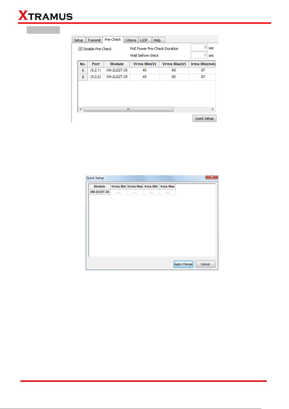
96
E-mail: sales@xtramus.com
Website: www.Xtramus.com
XTRAMUS TECHNOLOGIES®
C. Pre-Check
Disable Pre-Check: Click the check-box to disable the Pre-Check function. If the Pre-Check
function is disabled, no pre-test checks will be performed.
PoE Power Pre-Check Duration: The amount of time that will be used for Pre-Check test.
Wait Before Check: The amount of time that the system will wait before Pre-Check test.
Quick Setup: By clicking the Quick Setup button, a Quick Setup window will pop-up, allowing
you to set all the Active Ports at the same time.
Page 97
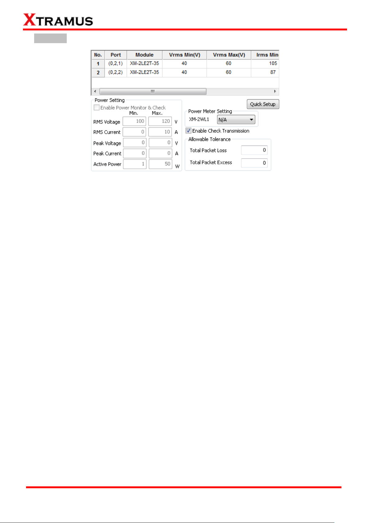
97
E-mail: sales@xtramus.com
Website: www.Xtramus.com
XTRAMUS TECHNOLOGIES®
D. Criteria
You can set criteria for tests by clicking on the variables, or you can click the Quick Setup button to set
multiple Active Ports at the same time.
Quick Setup: By clicking the Quick Setup button, a Quick Setup window will pop-up, allowing you
to set all the Active Ports at the same time.
Power Setting: This function allows you to check DUT‟s power status during the test. Please note
that if there is no power testing module card installed on the chassis, the Power Setting section will
be gray and thus unable to access.
Enable Power Monitor & Check: Click this check-box to enable Power Setting function. You
can set which port on the power testing module card to use by clicking the scroll-down menu.
RMS Voltage/Current, Peak Voltage/Current, and Active Power: You can set the criteria for
power testing in these fields.
Power Meter Setting: this function is available only when XM-2WL1 modules are installed. The
function is to test the electric parameters of DUT. Please select the XM-2WL1 module from the
scroll-down menu.
Enable Check Transmission: Enable this function and APMPT-4 will check transmitting packets.
Allowable Tolerance: You can set the allowable Packet Loss or Packet Excess here in these
fields.
Page 98

98
E-mail: sales@xtramus.com
Website: www.Xtramus.com
XTRAMUS TECHNOLOGIES®
E. LLDP
Enable LLDP: Selecting this function will unlock the section settings.
Port Mapping: list of port pair to be set in PG and PoE list. PG field is the packet generation port,
and PoE field is the power over Ethernet test port.
Quick Mapping: The window for the quick set of Port Mapping.
Reset: Reset all your Port Mapping settings.
Option:
Message Tx Interval: The time gap before packet generation.
Enable 802.3 Power via MDI: Select this function will enable the 802.3 power from MDI.
Enable Extended Power via MDI: Select this function will enable the extended power from
MDI.
F. Help
You can see the system status of your task on this field.
Page 99

99
E-mail: sales@xtramus.com
Website: www.Xtramus.com
XTRAMUS TECHNOLOGIES®
5.4.7. POE Dynamic A. Setup
Port: Select the port to perform dynamic loading function.
Loading No.: The order of loading.
Enable: Enable the loading to perform its function.
Load (Watt): The loading power in watts.
Time (sec): The time duration for loading.
Prepare Load (Watt): The initial loading power before the test.
Prepare Load Time (ms): The initial loading time before the test.
Class: The loading range in watts where Class 0 is 0.44 to 12.95, Class 1 is 0.44 to 3.84, Class 2
is 3.84 to 6.49, Class 3 is 6.49 to 12.95 and Class 4 reserved for PSE.
Delay time: The time delay between two Loading.
Total Loading Time: The total time for running all Loading.
Enable Line Emulation/Emulation Length (M): Emulate the test on the set cable length in meter.
Cable Select: Select the type of cable of the test.
Page 100

100
E-mail: sales@xtramus.com
Website: www.Xtramus.com
XTRAMUS TECHNOLOGIES®
Alternative: A network cable contains 4 twisted pair (8 totally) copper wire. The Alternative
function can lead input power from DUT to different pairs for the requirement of test allows you to
choose which pins provide the power. You can choose Mode A (Powered via Pin 1, 2, 3, and 6), or
Mode B (Powered via Pin 4, 5, 7, and 8). For more information regarding to network cable lines and
how they are related to RJ-45 jack, please refer to the Alternative explanation in 5.4.1 POE
Connect.
Halt on if Fail: The test will halt if the test fails.
Wait for Check Result: System will wait for the set amount of time before checking the test result.
Port Select: By clicking this button, a Select Ports for Testing window will pop up, allowing you to
select the module cards and the ports you would like to use for the task.
B. Help
You can see the system status of your task on this field.
 Loading...