

Page 1

NuDC-4U
User Manual
USM Ver 2.1
Page 2

Foreword
Copyright
Copyright © 2010 Xtramus Technologies, all rights reserved. The information contained in this document is the property of Xtramus
Technologies. No part of this publication shall be reproduced, stored in a retrieval system, or transmitted, in any form or by any
means, without the prior written permission of Xtramus Technologies.
Disclaimer
The information contained in this document is subject to change without notice and does not represent a commitment on the part of
Xtramus Technologies. The information in this document is believed to be accurate and reliable. However, Xtramus Technologies
assumes no responsibility or liability for any errors or inaccuracies that may appear in the document.
Trademarks
NuDC-4U is a trademark or registered trademark of Xtramus Technologies. All other trademarks and registered trademarks are the
property of their respective owners.
Warranty
Xtramus Technologies warrants for the hardware provided along with this document under proper usage and conditions in normal
environment; any improper operation or in irregular environment may possibly cause this product NOT function well. For detailed
terms, please contact your local dealer.
Contact Information
Xtramus Technologies
E-mail: sales@xtramus.com
Website: www.xtramus.com
Tel: +886-2-8227-6611
Fax: +886-2-8227-6622
XTRAMUS TECHNOLOGIES®
2
E-mail: sales@xtram u s .com
Website: www.Xtramus.com
Page 3

Revision History
Date USM Version History
August, 2009 1.0 First draft version
August, 2010 2.0
August, 2010 2.1
Changing manual format, adding new features, and
revising all previous manual.
Applying new warranty in Foreword section.
Adding notifications regarding about NuDC-4U’s
Parallel Connection Mode.
XTRAMUS TECHNOLOGIES®
3
E-mail: sales@xtram u s .com
Website: www.Xtramus.com
Page 4

Table of Contents
Foreword..........................................................................................................................................2
Revision History..............................................................................................................................3
1. NuDC-4U Overview......................................................................................................................5
1.1. General Description of NuDC-4U ......................................................................................5
1.2. Key Features & Main Applications of NuDC-4U...............................................................6
1.3. NuDC-4U Panel Functions Overview................................................................................7
2. DUT Power Status Measurement...............................................................................................9
2.1. Connecting NuDC-4U with PC...........................................................................................9
2.2. Connecting NuDC-4U with PCB ........................................................................................9
2.3. Connecting NuDC-4U with USB Device..........................................................................10
2.4. Connecting NuDC-4U with PoE (Power over Ethernet) Device....................................11
2.5. Connecting NuDC-4U with DC Plug Socket Device.......................................................12
2.6. Connecting NuDC-4U with Other DC Powered Device..................................................13
2.7. Other Testing Gadgets.....................................................................................................14
3. Install/Uninstall NuDC-4U.........................................................................................................15
4. NuDC-4U Utility Overview.........................................................................................................19
4.1. Starting NuDC-4U Utility ..................................................................................................19
4.2. NuDC-4U Main Window Overview...................................................................................20
5. NuDC-4U Utility Functions........................................................................................................21
5.1. Menu Bar...........................................................................................................................21
5.1.1. File ................................................................................................................................21
5.1.2. Setting ..........................................................................................................................22
5.1.3. Service..........................................................................................................................25
5.1.4. Languages....................................................................................................................25
5.1.5. Help...............................................................................................................................25
5.2. Quick Launch Buttons .....................................................................................................26
5.2.1. Reconnect....................................................................................................................26
5.2.2. Open .............................................................................................................................26
5.2.3. Save..............................................................................................................................26
5.2.4. Default ..........................................................................................................................27
5.2.5. Window A/B/C/D...........................................................................................................27
5.3. Power Measuring Scale ...................................................................................................28
5.4. Real-Time Statistic Table..................................................................................................30
5.5. Main Display Screen.........................................................................................................31
5.6. Power Test Status.............................................................................................................31
5.7. Test Control Buttons........................................................................................................32
5.8. Curve Moving Buttons .....................................................................................................32
5.10. Cursor Time ....................................................................................................................33
6. NuDC-4U Accessories/Maintenance........................................................................................34
6.1. NuDC-4U Accessories......................................................................................................34
6.2. Upgrading NuDC-4U’s Firmware/FPGA..........................................................................36
XTRAMUS TECHNOLOGIES®
4
E-mail: sales@xtram u s .com
Website: www.Xtramus.com
Page 5
1. NuDC-4U Overview
1.1. General Description of NuDC-4U
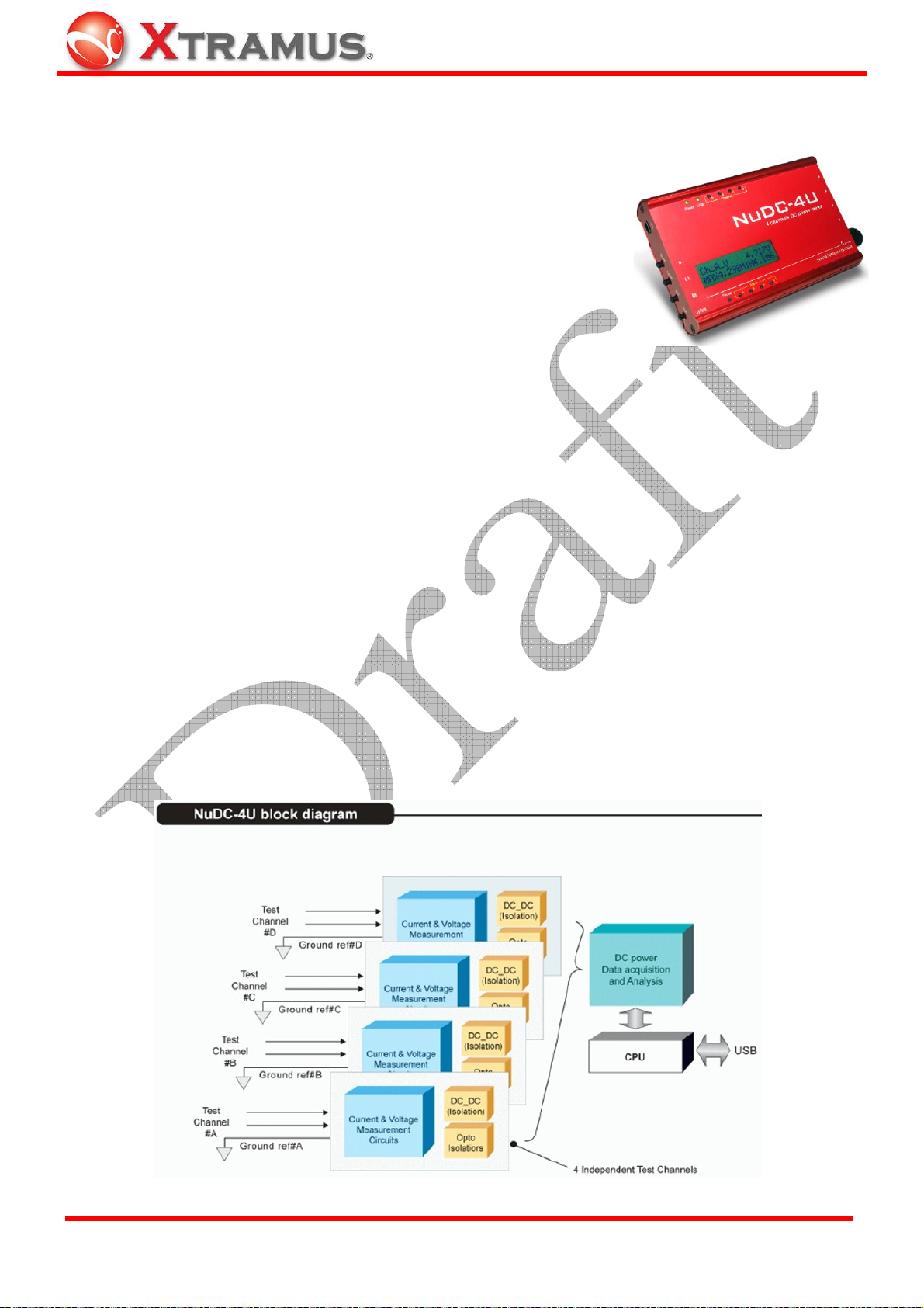
NuDC-4U is an innovative product that provides better solution for power
probing. Common DC power statistics including voltage, ampere and
even the watt can be read instantly via NuDC-4U. Moreover, up to 4 sets
of individual powers can be monitored simultaneously and the LCD
screen can also display the maximum and minimum value of the current
power during the test.
Besides displaying real-time power status, NuDC-4U can also record all variation of power status and
export it to PC via mini-USB port. When conducting long-time tests, NuDC-4U can automatically and
periodically save test logs to the folder in PC that users defined previously. Therefore, no testing data will
be lost during long testing periods. If the hardware fails, problems can be tracked down and analyzed
easily. Also, NuDC-4U can send e-mails to the user-defined e-mail address whenever an error occurs,
making it less likely for engineers to miss any crucial test results in a long testing time.
NuDC-4U has the ability to record 4,000 sample data within a second. However, in order to prevent PC
crash or lad caused by the enormous data flow, users can define the Display Rate with the utility software.
By defining Display Rate, users can set how many data should be sampled within 4,000 sample data
generated per second. Not only preventing PCs from crashing or lagging, but this feature also provides
more accurate maximum, minimum, and average values of the test.
For different testing requirements, NuDC-4U also has various optional accessories available. These
optional accessories include: USB interface for testing USB device power status, DC jack interface for
various sizes of the DC jack connectors, PoE interface for devices support Power over Ethernet, bare
wire connections for devices with no DC o4connectors, and mini daughter boards for PCB and SMD.
XTRAMUS TECHNOLOGIES®
5
E-mail: sales@xtram u s .com
Website: www.Xtramus.com
Page 6

1.2. Key Features & Main Applications of NuDC-4U
Key Features of NuDC-4U:
¾ Monitor 4 DC power sources channels simultaneously
¾ Voltage and current in each channel can be monitored at the same time
¾ Using mini-USB port as power source, as well as interface for accessing logs and utilities on PCs
¾ Utility softwares with oscilloscope-like user-interface with advanced functions such as split-screen,
curve select switch, resizing and overlapping
¾ When connecting to PC via mini-USB port, GUI utility softwares can provide long-time statistics in
diagrams
¾ LCD screen embedded on NuDC-4U with real-time statistic displaying function
¾ Various instant-readiness optional accessories
¾ E-mail notification by pre-defined alarm criteria from users
¾ High speed and accurate measurement of voltage, current and watt
¾ High speed and precise digitizing capture of power status
¾ Detection range from ±0.1V to ±70V, 10mA to 8A and 0.001W to 560W
¾ Detection current is up to 16A if circuits are connected in parallel by ASSY-DC SC4S accessory
board
Main Applications of NuDC-4U:
¾ Debug DC power problem of circuit board
¾ Long term monitoring of DC power supply
¾ Warning of unstable DC power supply
¾ Trace specified power status events
¾ Compare variation of the same test circuit design on different DUT.
¾ Detect degradation of electronic component.
XTRAMUS TECHNOLOGIES®
6
E-mail: sales@xtram u s .com
Website: www.Xtramus.com
Page 7
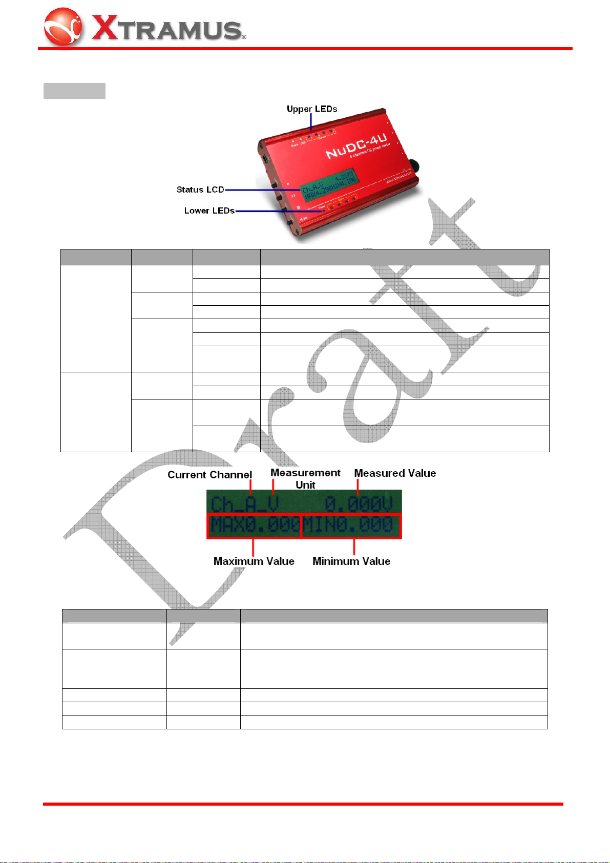
1.3. NuDC-4U Panel Functions Overview
Front Panel
LEDs Label Status Description
ON NuDC-4U is power on and ready for tests
OFF NuDC-4U is power off
ON NuDC-4U is connected to PC via USB cable
OFF NuDC-4U is NOT connected to PC via USB cable
Yellow Channel A/B/C/D is connected to a power-on DUT
Green Channel A/B/C/D is connected to a power-off DUT
Blinking
Green
ON Pausing current Power Status readings displayed on LCD
OFF Power Status readings is displaying on LCD in real-time
ON
OFF
Upper LEDs
Lower LEDs
Power
USB
Channel
A ~ D
Pause
Alarm
A ~ D
Channel A/B/C/D is connected to a power-off DUT, and
Power Status of channel A/B/C/D are displayed on LCD
Current power status of channel A/B/C/D exceeds pre-set
alarm criteria
Current power status of channel A/B/C/D is under pre-set
alarm criteria, or no alarm criteria is not configured
NuDC-4U is embedded with a 2x16 characters LCD for displaying NuDC-4U system and power status.
Item Mark Description
Current Channel Ch_X
Measurement Unit
-V / -I / -W
Show power status of current channel. "X" represents the 4
channels of NuDC-4U: A, B, C, and D
¾ V: Voltage
Unit of power status:
¾ I: Ampere
¾ W: Watt
Measured Value Current value in Volt, Ampere or Watt
Maximum Value
Minimum Value
XTRAMUS TECHNOLOGIES®
MAX Maximum value during the test period
MIN Minimum value during the test period
7
E-mail: sales@xtram u s .com
Website: www.Xtramus.com
Page 8
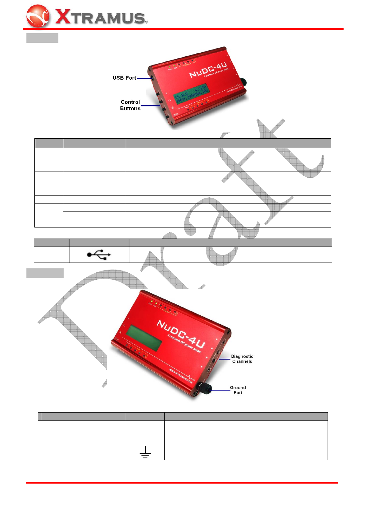
Left Panel
Button Action Description
Channel selection button: Select the channel (A/B/C/D) status that
will be shown on LCD. To switch channel A/B/C/D, pressing this
button multiple times until your choice is displayed on LCD.
Function selection button: Switch value between voltage, ampere or
watt on LCD. To switch voltage/ampere/watt, pressing this button
multiple times until your choice is displayed on LCD.
n
( )
r
Press
(Once or more)
Press
(Once or more)
Press Once Save maximum and minimum power status of all 4 channels
Press Once Pause/Clear button: Pause reading on LCD of all channels
l l /000
Hold 2 Seconds
Pause/Clear button: Clear maximum and minimum value of selected
channel
Port Label Description
Mini-USB
Serve as NuDC-4U’s power source and data
transmitting/receiving port.
Right Panel
Diagnostic Channel
Port Label Description
Channel A/B/C/D diagnostic port. There are two
A ~ D
Ground port
A/B/C/D
cords inside each diagnostic channel and works with
ground port (mentioned below) as a pair.
Ground port to DUT that work with diagnostic port as
a pair.
XTRAMUS TECHNOLOGIES®
8
E-mail: sales@xtram u s .com
Website: www.Xtramus.com
Page 9
2. DUT Power Status Measurement
The following chapter will guide you with wiring/connecting your DUT with NuDC-4U and performing DUT
power status measurement.
Hardware Installation
There are several accessories provided for the connection to most of DC powered device. Please read
the instruction below.
2.1. Connecting NuDC-4U with PC
Connect USB port of NuDC-4U to PC or external power adaptor. If it is connected to PC, PC can control
and also provides power to the NuDC-4U.
2.2. Connecting NuDC-4U with PCB
Connect USB port of NuDC-4U to PC or external power adaptor. If it is connected to PC, PC can control
and also provides power to the NuDC-4U.
¾ Connection of ground pole
In the design of PCB, it should has ground PIN for the test purpose. All components use the same ground
(negative pole) and all ground conductors are linked together electronically. Connect the ground (negative
pole) to the ground connector of NuDC-4U. Several accessory daughter boards can be soldered on the
same PCB and use the same ground PIN.
¾ Connection of diagnostic channel
There are two conductors inside a channel port. Solder the two conductors (C&B) to the both side (Y&Z)
of the component under test by optional accessories. There is no difference if user swaps the sequence of
wire. For example, solder wire C to Y location and solder wire B to Z location.
ASSY-DC L0805, L1206, and L0603 are mini daughter boards with two soldering conductors for soldering
on PCB (printed circuit board). Two conductors of the accessory can be soldered on the surface of PCB.
The three accessories have different conductor width for testing on PCB with different width of soldering
points.
XTRAMUS TECHNOLOGIES®
9
E-mail: sales@xtram u s .com
Website: www.Xtramus.com
Page 10
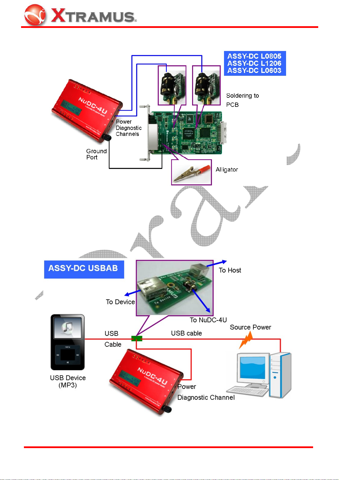
Up to 4 channel of measurement points can be measured simultaneously.
2.3. Connecting NuDC-4U with USB Device
For USB device, Xtramus provides optional accessory ASSY-DC USBAB for the test. It is a connection
board for monitoring the power status of USB device. Ports of ASSY-DC USBAB are all female ports.
Connecting ASSY-DC USBAB between the PC (or a USB power adaptor) and the USB device. After that,
connect NuDC-4U in order to monitor the power status.
XTRAMUS TECHNOLOGIES®
10
E-mail: sales@xtram u s .com
Website: www.Xtramus.com
Page 11
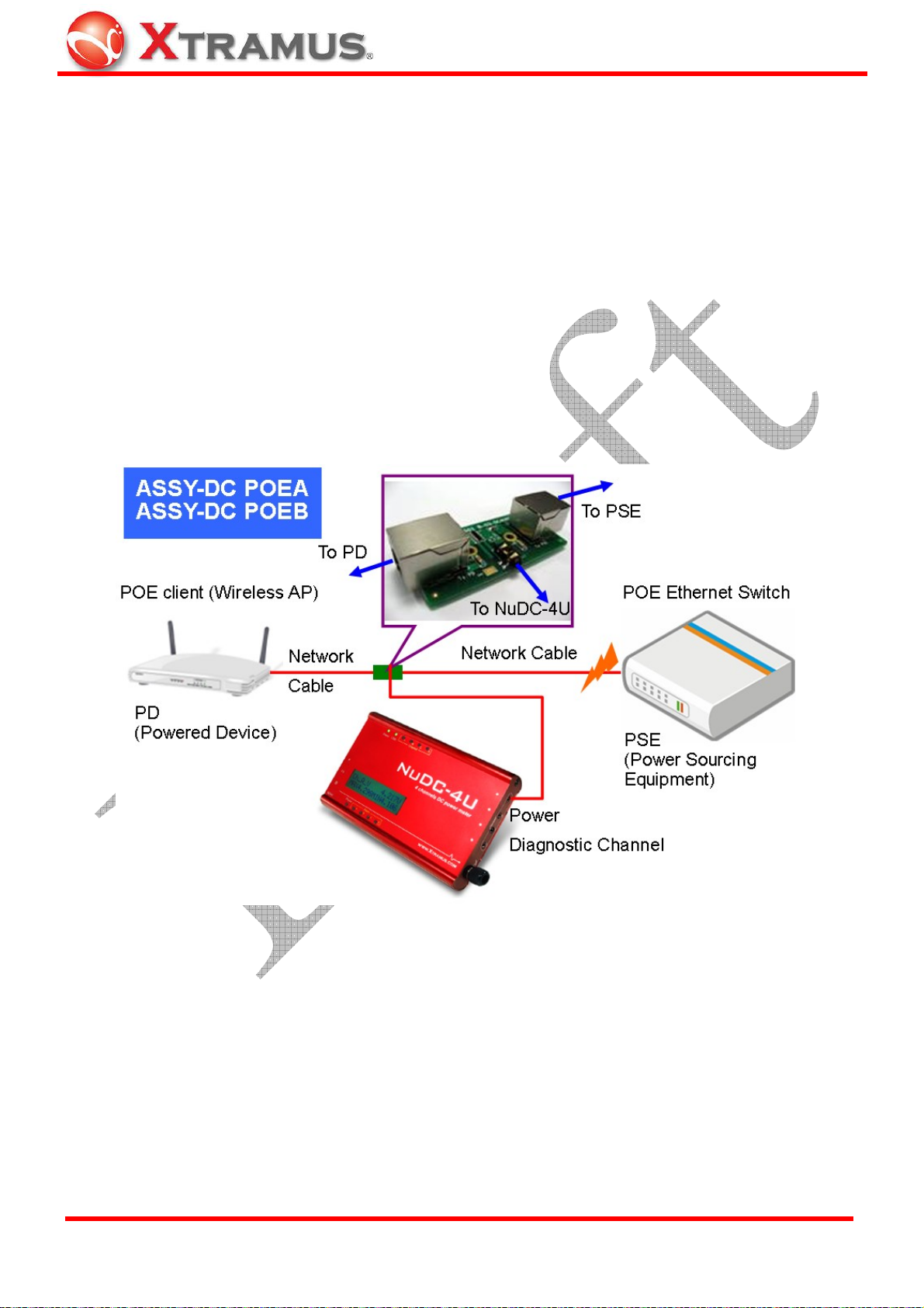
2.4. Connecting NuDC-4U with PoE (Power over Ethernet) Device
For PD device of PoE, Xtramus provides optional accessories ASSY-DC POEA, ASSY-DC POEB for the
test. It is a connection board for monitoring the power status of PSE device.
¾ PoE (Power over Ethernet): Power over Ethernet or PoE technology (commonly referred as IEEE
802.3af) describes a system able to transfer electrical power, along with data, to remote devices over
standard twisted-pair cable in an Ethernet network.
¾ PSE (Power Sourcing Equipment): Power Sourcing Equipment is a device (Ethernet Switch for
instance) that will be the power source in a PoE structure.
¾ PD (Powered Device): A powered device is a device powered by a PSE.
Connect this board between PoE switch and the PD device. After that, connect NuDC-4U in order to
monitor the power status.
XTRAMUS TECHNOLOGIES®
11
E-mail: sales@xtram u s .com
Website: www.Xtramus.com
Page 12
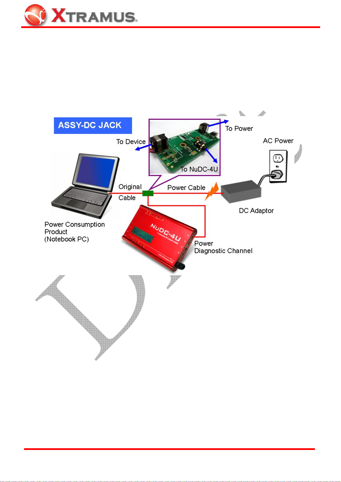
2.5. Connecting NuDC-4U with DC Plug Socket Device
For DC powered device that has DC plug socket, Xtramus provides optional accessories ASSY-DC JACK
for the test.
ASSY-DC JACK is a connection board for monitoring the power status of devices with DC
jacks. The specifications of DC jacks may be different in core diameters. Before connecting ASSY-DC
JACK to the testing device, please be sure that the size of the DC jacks are matched.
Connect this board between power adaptor and the device that consume DC power. After that, connect
NuDC-4U in order to monitor the power status.
XTRAMUS TECHNOLOGIES®
12
E-mail: sales@xtram u s .com
Website: www.Xtramus.com
Page 13

2.6. Connecting NuDC-4U with Other DC Powered Device
For other devices powered by DC, their connectors may be varied. It is difficult to have power analysis
equipment that has all connectors for all DUT. To solve the problem, fasten up the wire to the extension
board ASSY-DC SC4S directly is the simple way.
ASSY-DC SC4S is a connection board for monitoring the power status of DC powered device. Connect
this extension board between the DC power source and the power consumption device. After that,
connect NuDC-4U for monitoring the power status.
The simplest way is to fasten up the wire to the extension board directly. Also, clamping the Y-shape
terminal and then fasten it up to the extension board can fasten the wire tighter and more stable.
Binding of Y Terminal
XTRAMUS TECHNOLOGIES®
13
E-mail: sales@xtram u s .com
Website: www.Xtramus.com
Page 14

2.7. Other Testing Gadgets
Users can make their own power testing tools with most common gadgets listed below:
¾ Alligator Clip
With its spring-loaded jaws, an alligator clip can grip DUT’s
conductor firmly. However, please be sure that both of the
alligator clip’s jaws are gripping DUT’s conductors properly before
performing power tests. If the alligator clip’s jaws are not gripping
DUT’s conductors properly, short circuit might occur.
¾ Detection Probe
Commonly used for DVM, detection proves can also be used on
NuDC-4U. You can hold the detection probes and probe DUT’s
conductors when performing power tests. However, please make
sure that do not cross the metal part of two detection probes during
DUT power test. Doing so might cause short circuit, and should be
avoided.
XTRAMUS TECHNOLOGIES®
14
E-mail: sales@xtram u s .com
Website: www.Xtramus.com
Page 15

3. Install/Uninstall NuDC-4U
NuDC-4U comes with GUI (graphic user interface) utility software for setting test criteria and system
management. When NuDC-4U is connected with PC via a USB cable, you can set test criteria, save/view
testing logs, and upgrade NuDC-4U’s firmware/FPGA with NuDC-4U’s utility software.
However, before using NuDC-4U utility’s features and functions, you have to install it on your PC first.
Please see the table down below for PC’s system requirement for NuDC-4U Utility:
System Requirement for NuDC-4U Utility Software
OS
Windows XP Windows Vista
CPU 800MHz CPU 1.6 GHz, 32 bits (x86) CPU
RAM 256MB RAM 1GB RAM
HDD 20MB available space 20MB available space
NuDC-4U’s driver is contained in NuDC-4U’s utility software. Both NuDC-4U’s driver and utility software
will be installed at the same time. Please note that DO NOT connect your NuDC-4U to the PC via USB
cable before the installation.
Please follow the steps down below to install both NuDC-4U’s driver and utility software.
NuDC-4U Utility Software Installation
1. Double-click NuDC-4U installation program and
start the installation process.
XTRAMUS TECHNOLOGIES®
2. InstallShield Wizard is starting to install
NuDC-4U. If you would like to cancel installation,
click “Cancel”.
15
E-mail: sales@xtram u s .com
Website: www.Xtramus.com
Page 16

NuDC-4U Utility Software Installation
3. Click “Next” to continue installation.
4. Click “I accept the terms in the license
agreement”, and click “Next” to continue.
5. Input customer information (user name and name
of organization) and click
Next for next step.
XTRAMUS TECHNOLOGIES®
16
E-mail: sales@xtram u s .com
Website: www.Xtramus.com
Page 17

NuDC-4U Utility Software Installation
6. Click the Change… button to install the program
to another folder, or click
Next button to install the
program into the default destination folder, and then
continue next step. Click
Back button to go back to
the previous step to modify.
7. NUDC-4U InstallShield Wizard will start installing
momentarily. Click
Install button if the information is
correct.
XTRAMUS TECHNOLOGIES®
8. InstallShield Wizard is installing NUDC-4U.
17
E-mail: sales@xtram u s .com
Website: www.Xtramus.com
Page 18

NuDC-4U Utility Software Installation
9. NUDC-4U installation completes. Click Finish
button to exit.
There are two ways to uninstall NuDC-4U utility software:
NuDC-4U Utility Software Un-installation
• Click Start Æ Programs Æ Xtramus Æ
NUDC-4U Utility Æ Uninstall NUDC-4U
Utility.
• Go to the Control Panel, choose
NUDC-4U Utility from installed program
list, and click “Remove” to uninstall.
XTRAMUS TECHNOLOGIES®
18
E-mail: sales@xtram u s .com
Website: www.Xtramus.com
Page 19

4. NuDC-4U Utility Overview
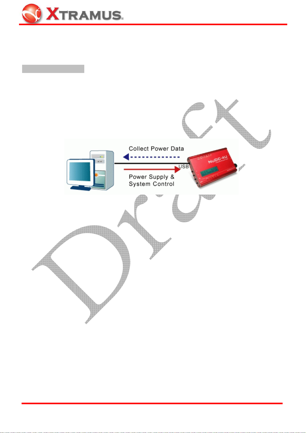
4.1. Starting NuDC-4U Utility
Before starting NuDC-4U utility, please be sure that NuDC-4U is connected to your PC via a USB cable
as shown in the figure down below:
To start NuDC-4U utility, you can:
Starting NuDC-4U
• Double-click NuDC-4U Utility icon located
on your PC’s desktop
• Click Start Æ Programs Æ Xtramus Æ
NUDC-4U Utility
Æ NUDC-4U Utility.
If your PC is not connected with NuDC-4U, you can still run NuDC-4U utility under Demo Mode. Almost all
NuDC-4U’s functions are available under Demo Mode. However, please note that Demo Mode is for
system demo purposes only, and does not serve any testing purposes at all.
XTRAMUS TECHNOLOGIES®
19
E-mail: sales@xtram u s .com
Website: www.Xtramus.com
Page 20

4.2. NuDC-4U Main Window Overview
NuDC-4U Main Window
NuDC-4U Utility Functions Overview
The Menu Bar allows you to make settings about test criteria,
A Menu Bar
view/save test log, change language displayed, and update NuDC-4U’s
firmware/FPGA.
The Quick Launch Buttons allow you to reconnect your PC to
B Quick Launch Buttons
NuDC-4U, open/save test logs, and switching Main Display Screen
display mode.
C Power Measuring Scale
D Real-time Statistic Table
E Main Display Screen
F Power Test Status
G Test Control Buttons
H Curve Moving Buttons
I Horizontal Scale Adjust
J Cursor Time
K USB Connection Status
You can set the display scale (Voltage, Ampere, and Watt) for Channel
A/B/C/D.
Statistics regarding to the power test will be displayed here in this table.
Power test status will be displayed here in this chart.
This icon will indicate if alarm happens during the test.
The Test Control Buttons allow you to control the process of tests.
You can move selected curve line displayed in Main Display Screen
up/down/right/left.
You can set the scale for the X-Axis of the Main Display Screen.
This section shows the Cursor Time of C1/C2, and the time duration
in-between C1 and C2.
This icon shows the connection status between your PC and NuDC-4U.
XTRAMUS TECHNOLOGIES®
20
E-mail: sales@xtram u s .com
Website: www.Xtramus.com
Page 21

5. NuDC-4U Utility Functions
5.1. Menu Bar
NuDC-4U utility software’s Menu Bar contains configuration options such as File, Setting, Service,
Language, and Help. Please refer to the sections down below for detail information regarding to each
configuration option.
5.1.1. File
Function Descriptions – File
You can open previously saved log
files with the Open Log function. All
statistics regarding to the test log
you chose will be displayed on D.
Real-time Statistic Table and E.
Main Display Screen.
Open Log
The default file path where all the
test logs are saved is: “C:\NuDC-4U
Utility.log”.
Save Log
Load Default Config
Exit
XTRAMUS TECHNOLOGIES®
You can save the current test result
on your PC. All test logs are saved
in the format of “*.csv”.
The default file path where all the
test logs are saved is: “C:\NuDC-4U
Utility.log”.
The Load Default Config function
allows you to set all NuDC-4U’s settings
to default value. Click YES to load
NuDC-4U’s default value, or click NO to
cancel.
A prompt pop-up window will ask if you are sure to exit APMPT-4. Click YES to exit
NuDC-4U utility software, or click NO to cancel.
21
E-mail: sales@xtram u s .com
Website: www.Xtramus.com
Page 22

5.1.2. Setting
Function Descriptions – Setting
Alarm
When clicking Alarm on the Menu Bar, an Alarm Setting window will pop up,
allowing you to make test alarm configurations.
• Ch_A/B/C/D: Clicking the Ch_A/B/C/D menu tabs allows you to switch alarm
setting pages of Channel A/B/C/D.
• Voltage/Current: These two fields allow you to set alarm criteria for DUT’s
voltage (Volt) and current (Ampere). Click Enable check- box to start
configuring alarm criteria. Click the scroll-down menu to set the condition for
the voltage/current threshold value you input:
¾ >=: If DUT’s voltage/current value is greater or equal to the value you set
here, system will issue an alarm.
¾ <=: If DUT’s voltage/current value is lesser or equal to the value you set
here, system will issue an alarm.
XTRAMUS TECHNOLOGIES®
22
E-mail: sales@xtram u s .com
Website: www.Xtramus.com
Page 23

Function Descriptions – Setting
• Connection Mode: NuDC-4U utility soft ware can send you e-mails if you
enable “Send E-mail alarms to an E-mail box” function. If you click the
Alarm
(Continued)
“E-mail Box Settings” button after enabling this function, an E-mail Setting
window will pop up. Please note that your PC must have Internet access to
send alarm e-mails.
¾ POP3 Server Address: Please input the POP3 server address of your
¾ E-mail Box Account/Password: Please input your e-mail’s account
¾ Sender’s E-mail Address: Please input your e-mail address here.
¾ Destination E-mail Address: Please input the e-mail address that you
¾ E-mail Sending Interval (min): You can set the time interval between
• Buzzer Setting: Click the Buzzer On check-box, NuDC-4U will buzz
whenever the DUT’s voltage/current meets the alarm criteria you set.
e-mail here in this field.
/password here in these fields.
would like to send the alarm e-mails to.
alarm e-mails here.
Trigger
*Please note that when switching NuDC-4U's connection mode under Parallel
Connection Mode, all Alarm settings will be DISABLED.
You can configure several sets of
trigger condition with NuDC-4U utility
for tracing certain cases or errors.
Either Voltage, Current (ampere) or
Power (watt) can be configured as a
trigger condition. When the device
under test meets these conditions (or in
others words, equal to the value
configured in the trigger condition), the
trigger condition occurrence time will be
recorded in the log.
• A: Click the scroll-down menu to
choose Channel A/B/C/D.
• B: Click the scroll-down menu to
choose Voltage, Current, or Power.
• C: Click the scroll-down menu to set the condition (>= or <=) for the criteria
value you set in D.
• D: You can set the criteria value here.
• E: Click Add to add the setting you’ve set to the T rigger Table F down below;
or choose a trigger listed in Trigger Table F, and click Delete to delete it.
• F: The Trigger Table. All the criteria you’ve set will be displayed here.
XTRAMUS TECHNOLOGIES®
Click OK to apply all the changes you’ve made, or click Cancel to exit.
23
E-mail: sales@xtram u s .com
Website: www.Xtramus.com
Page 24
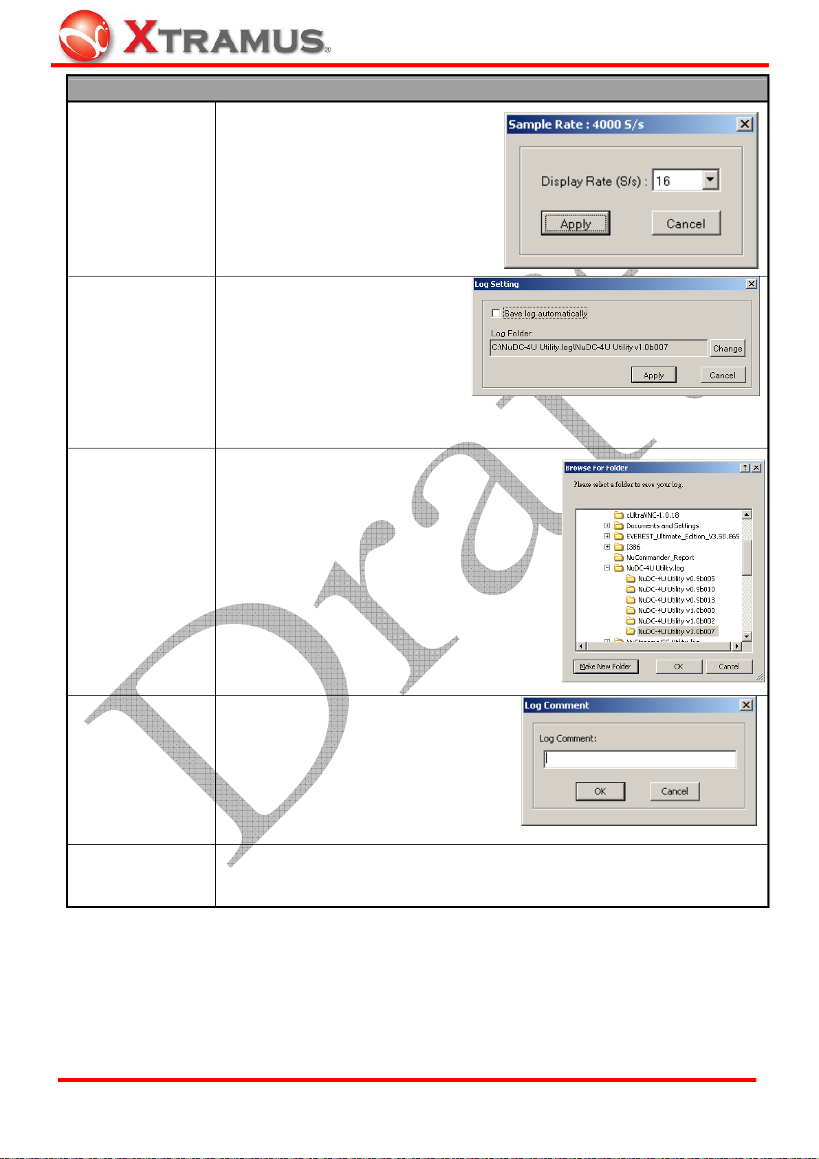
Function Descriptions – Setting
When clicking Display Rate on the
Menu Bar, a Sample Rate window will
pop up, allowing you to set the display
rate of the real-time chart on Main
Display Rate
Display Screen.
When clicking Log Saving on the
Menu Bar, a Log Setting window
will pop up. You can set if you would
like to Save log automatically by
Log Saving
clicking the check box, or change
the file folder for saving test logs by
clicking the Change button.
For more information regarding to changing log folder, please refer to Log Folder
section listed down below.
When clicking Log Folder on the Menu Bar, a
Browse for Folder window will pop up. You can
set the folder for saving test logs here in this
window.
Log Folder
Log Comment
Enable Ch_A/B/C/D
• Make New Folder: Click this button to create
a new folder in the current file path.
• OK/Cancel: Click OK to apply all the
changes you’ve made, or click Cancel to exit
this window without changing anything.
You can enter comments for the current
test in the pop-up Log Comment window.
You can set to enable/disable Channel A/B/C/D by clicking Enable CH_A/B/C/D.
Channels that are enabled have a check mark “
✔” before it.
XTRAMUS TECHNOLOGIES®
24
E-mail: sales@xtram u s .com
Website: www.Xtramus.com
Page 25

5.1.3. Service
Function Descriptions – Service
You can upgrade NuDC-4U’s firmware or FPGA (Field Programmable Gate Array)
with System Upgrade function.
System Upgrade
For detail information regarding to updating NuDC-4U’s firmware or FPGA, please
refer to 6.2. Upgrading NuDC-4U’s Firmware/FPGA.
Show Log
All test statistics will be displayed in the pop-up Device Log window. You can click
the Normal Mode Record or Parallel Connection Mode Record menu tabs to
view test logs.
Clear Log
Open Log Folder
Clear all the statistics listed in Device Log.
Open the folder where all test logs are saved.
5.1.4. Languages
Function Descriptions – Languages
English
Simplified Chinese
Switch NuDC-4U utility software’s language display to English.
Switch NuDC-4U utility software’s language display to Simplified Chinese.
5.1.5. Help
Function Descriptions – Help
About
Xtramus Web
XTRAMUS TECHNOLOGIES®
An “About” window will pop up and show detailed system information.
Access Xtramus Website (www.xtramus.com).
25
E-mail: sales@xtram u s .com
Website: www.Xtramus.com
Page 26

5.2. Quick Launch Buttons
5.2.1. Reconnect
Function Descriptions – Reconnect
If the USB connection between your PC and NuDC-4U is down, a “Disconnected” icon
will be shown in “USB Connection Status”.
Press Reconnect button
the connection has been established successfully, the “USB Connection Status” will be shown as
“Connected”
5.2.2. Open
Function Descriptions – Open
The Open button serves the same functions
as Open Log function on the Menu Bar.
You can open previously saved log files with
the Open Log function. All statistics
regarding to the test log you chose will be
displayed on D. Real-time Statistic Table
and E. Main Display Screen.
The default file path where all the test logs
are saved is: “C:\NuDC-4U Utility.log”.
5.2.3. Save
to re-establish the connection between your PC and NuDC-4U. If
.
Function Descriptions – Save
The Save button serves the same functions
as Save Log function on the Menu Bar.
You can save the current test result on your
PC. All test logs are saved in the format of
“*.csv”.
The default file path where all the test logs
are saved is: “C:\NuDC-4U Utility.log”.
XTRAMUS TECHNOLOGIES®
26
E-mail: sales@xtram u s .com
Website: www.Xtramus.com
Page 27

5.2.4. Default
Function Descriptions – Default
Click this button to set all criteria you set to the default
value. A message window will pop up. Click YES to set
all criteria to the default value, or click NO to cancel.
5.2.5. Window A/B/C/D
Function Description – Window A/B/C/D
By clicking these four buttons (Window A/B/C/D), you can set different display mode for
the Main Display Screen.
One Chart Mode: Display statistics of
Channel A/B/C/D in the same chart.
Two Charts Mode: Display statistics of
Channel A/C and B/C in two different charts.
Four Charts Mode: Display statistics of
Channel A/B/C/D in 4 different charts.
Parallel Connection Mode: Display two pair
of connections in the same chart.*
* Please note that due to NuDC-4U's hardware limitations, NuDC-4U’s Alarm LEDs and LCD will only display Ch_A
status under Parallel Connection Mode.
XTRAMUS TECHNOLOGIES®
27
E-mail: sales@xtram u s .com
Website: www.Xtramus.com
Page 28

5.3. Power Measuring Scale
NuDC-4U has 4 ports that serve as Diagnostic Channels A/B/C/D. In corresponding to these Diagnostic
Channels, NuDC-4U utility software’s Power Measuring Scale contains separate sections for changing
Channel A/B/C/D displaying scale as shown in the figures down below:
You can set the display scale of DUT’s Voltage (V), Ampere (A), and Watt (W) with the scroll-down menu
here in these fields. Each Channel’s Voltage (V), Ampere (A), and (Watt) curves displayed on the Main
Display Screen are represented with different colors as shown in the table down below:
Channel A (Ch_A) Channel C (Ch_C)
XTRAMUS TECHNOLOGIES®
Channel A, Voltage Channel C, Voltage
Channel A, Ampere Channel C, Ampere
Channel A, Watt Channel C, Watt
Channel B (Ch_B) Channel D (Ch_D)
Channel B, Voltage Channel D, Voltage
Channel B, Ampere Channel D, Ampere
Channel B, Watt Channel D, Watt
28
E-mail: sales@xtram u s .com
Website: www.Xtramus.com
Page 29

The display scales for Voltage (V), Ampere (A), and (Watt) can be set with the scroll-down menu in these
fields. Display scales available for Voltage (V), Ampere (A), and (Watt) are shown in the table down
below:
Voltage (V)
Ampere (A)
Watt (W)
100mV, 200mV, 500mV, 1V, 2V, 5V, 10V, 20V
100mA, 200mA, 500mA, 1A, 2A, 5A
100mW, 200mW, 500mW, 1W, 2W, 5W, 10W, 20W, 50W, 70W, 90W
If you set the display scale of Voltage (V), Ampere (A), or (Watt) to a larger scale, the corresponding curve
displayed on the Main Display Screen will be smoother than the curves with smaller scale, as shown in
the figures down below:
Ch_A_V Curve: Set as 1V
Ch_A_V Curve: Set as 5V
You can choose specific curve displayed on the Main Display Screen. The curve you chose will be
thicker and highlighted in white as shown in the figures down below:
Ch_A_V Curve: Not chosen
Ch_A_V Curve: Chosen and Highlighted
To select a curve, please click the empty space in front of the curve you
would like to choose. An arrow icon
will appear when a curve is chosen.
You can move the curve you’ve chosen with Curve Moving Buttons as
well.
Also, you can choose which curve shall be displayed on the Main Display
Screen by clicking the colored square in front of it, as shown in the figure at
right. The curve you’ve chosen this way will only be hidden. Tests regarding
to that curve will still be running. The colored square that represents the
curve will be replaced by a grave square icon
if it is hidden.
XTRAMUS TECHNOLOGIES®
29
E-mail: sales@xtram u s .com
Website: www.Xtramus.com
Page 30

If you set the Main Display Screen’s display mode to Parallel Connection
Mode by clicking the Window D button on the Quick Launch Buttons, the
Power Measuring Scale will be as shown in the figure at right.
Under Parallel Connection Mode, NuDC-4U’s Channels are paired and will
be displayed in the same chart. Click the Connection Mode scroll-down
menu to choose how you would like to pair these 4 channels.
• Ch_AB and Ch_CD: Channel A and Channel B will be paired, while
Channel C and Channel D will be paired.
• Ch_AC and Ch_BD: Channel A and Channel C will be paired, while
Channel B and Channel D will be paired.
• Ch_AD and Ch_BC: Channel A and Channel D will be paired, while
Channel B and Channel C will be paired.
• Apply: Click this button to apply the changes you’ve made.
5.4. Real-Time Statistic Table
All test statistics will be shown here in real-time. Statistics listed here in the Real-Time Statistic Table
include:
Statistics Description
Instant
Cursor 1/2
Average
Max
Min
Trigger
Current power status.
Power status value at Cursor 1/2 vertical line. You can change the position of
Cursor 1/2 on the Main Display Screen.
The average power status value of the channel.
The maximum power status value of the channel.
The minimum power status value of that channel.
The power status value when the power status value you’ve set is triggered during
the test.
XTRAMUS TECHNOLOGIES®
30
E-mail: sales@xtram u s .com
Website: www.Xtramus.com
Page 31

5.5. Main Display Screen
The Main Display Screen displays real-time power status in curves, while Voltage/Ampere/Watt serves
as each curve’s Y-Axis, and time as its X-Axis. There are four different modes for the Main Display
Screen, which are: One Chart Mode, Four Charts Mode, Two Charts Mode, and Parallel Connection
Mode. For more information, please refer to “5.2.5. Window A/B/C/D”.
You can change the location of Cursor 1 and Cursor 2 on the Main Display Screen. Move the
mouse on the cursor you would like to move. Your mouse will change to “ÅÆ” icon as shown in
the figure at right. Left-click and hold your mouse so you can move Cursor 1 or Cursor 2 to the
location you wants.
5.6. Power Test Status
The Power Test Status icon located on the upper-right part of NuDC-4U utility software changes
whenever alarm has occurred during power test as shown in the table down below:
No alarm has occurred.
An alarm has occurred.
XTRAMUS TECHNOLOGIES®
31
E-mail: sales@xtram u s .com
Website: www.Xtramus.com
Page 32

5.7. Test Control Buttons
Button Description
Click the Run button to start the test. Statistics of the power test will be shown on the
Real-Time Status Table and curves will start be generated on the Main Display
Screen.
Click the Stop button to stop the test. Statistics of the power shown on the Real-Time
Status Table and curves generated on the Main Display Screen will stop as well.
Click the Clear button to clear all the statistics of the power shown on the Real-Time
Status Table and curves generated on the Main Display Screen.
Click the Trigger button BEFORE the test, a purple trigger line will appear
on the Main Display Screen when the values set as trigger are met during
test.
Click the Freeze Chart check box and the curves generated on the Main Display
Screen will freeze while the power test is still running.
5.8. Curve Moving Buttons
Button Description
Move the selected cursor on the Main Display Screen up/down. To select a cursor,
please refer to “5.3. Power Measuring Scale”.
Move all the cursors on the Main Display Screen left/right. To move all the cursors to
the far left/right, click
XTRAMUS TECHNOLOGIES®
or buttons.
32
E-mail: sales@xtram u s .com
Website: www.Xtramus.com
Page 33

5.9. Horizontal Scale Adjust
The Horizontal Scale menu bar allows you to adjust the X-Axis of the chart displayed on the Main
Display Screen. You can set the X-Axis of the chart from 100ms to 1 hour.
5.10. Cursor Time
As shown in the figure down below, Cursor 1 and Cursor 2 are two vertical lines that located on the Main
Display Screen. The Curse Time table shows the time of Cursor 1 and Cursor 2.
The Delta Time on the Cursor Time is the time duration in-between the time of Cursor 1 and Cursor 2.
You can change the time of Cursor 1 and Cursor 2. For more information regarding to change the time of
Cursor 1 and Cursor 2, please refer to “5.5. Main Display Screen.”
XTRAMUS TECHNOLOGIES®
33
E-mail: sales@xtram u s .com
Website: www.Xtramus.com
Page 34

6. NuDC-4U Accessories/Maintenance
6.1. NuDC-4U Accessories
NuDC-4U has many different accessories available for different testing tasks. These accessories include:
NuDC-4U Accessories
ASSY-DC SC4S: Extension board for connecting DC devices with no connector.
The detection range of the current can be doubled if wires are fastened in parallel.
Bare Wire Connection
PoE Device
ASSY-DC POEA: Connection board for monitoring the power status of PD
(Powered Device) of PoE. (Power via Pin 1, 2, 3, 6) - Mode A
ASSY-DC POEB: Connection board for monitoring the power status of PD
(Powered Device) of PoE. (Power via Pin 4, 5, 7, 8) - Mode B
USB Device
DC Jack Device
PCB and SMD
ASSY-DC USBAB: Connection boards for monitoring USB devices’ power status
ASSY-DC JACK: Connection boards for monitoring power status of devices with
different kinds of DC Jacks. Models for different sizes of DC Jack are shown below:
¾ ASSY-DC JACK065: ψ0.65mm
¾ ASSY-DC JACK165: ψ1.65mm
¾ ASSY-DC JACK235: ψ2.35mm
¾ ASSY-DC JACK13: ψ1.3mm
¾ ASSY-DC JACK20: ψ2.0mm
¾ ASSY-DC JACK25: ψ2.5mm
ASSY-DC: Mini daughter board with two soldering conductors for soldering on PCB.
Models with different widths of conductors are shown below:
¾ ASSY-DC L1206
¾ ASSY-DC L0805
¾ ASSY-DC L0603
XTRAMUS TECHNOLOGIES®
34
E-mail: sales@xtram u s .com
Website: www.Xtramus.com
Page 35

Please note that, for the convenience of performing power tests, the accessory boards mentioned above
are not covered with outer cases. Due to this reason, it is important to handle NuDC-4U’s accessory
boards with care when performing power tests. Also, please
• Static electricity might cause damages to NuDC-4U’s accessory boards, and should be avoided.
• When plugging cable connectors into sockets, please do so in a vertical angle to prevent damaging
the core and pins inside the socket.
• Please hold the connector when removing cable. Removing the cable by pulling it out from its
socket might cause damages.
• When holding NuDC-4U’s accessory boards, please hold the edge of the accessory boards without
touching any components on the accessory boards.
• DC jacks soldered on PCB are disposable when damaged. Please contact your distributor for
purchasing new DC jacks if you would like to replace your damaged DC jacks.
• When using probes or alligator clips, please be aware of short circuit.
• Before connecting NuDC-4U and its accessory boards, please make sure that all the
wiring/connection is correct.
• NuDC-4U’s detection ranges for voltage/ampere/watt are 0.1V to 55V DC, 10mA to 8A and
0.001W to 440W. Performing tests on DUT that’s beyond NuDC-4U’s voltage/ampere/watt
detection ranges will damage your NuDC-4U, and should be avoided.
XTRAMUS TECHNOLOGIES®
35
E-mail: sales@xtram u s .com
Website: www.Xtramus.com
Page 36

6.2. Upgrading NuDC-4U’s Firmware/FPGA
Before upgrading NuDC-4U’s firmware/FPGA, please be sure that your NuDC-4U is connected to PC via
a USB cable as shown in the figure down below:
The following instructions are for upgrading NuDC-4U’s firmware. The process for upgrading NuDC-4U’s
FPGA is identical to upgrading NuDC-4U’s firmware, and can be related.
Upgrading NuDC-4U’s Firmware/FPGA
Click Service on the Menu Bar, and then choose
System Upgrade Æ Firmware Upgrade/FPGA
Upgrade.
A Load File window will pop up. Choose the
firmware/FPGA file you would like to upgrade, and
click Open.
Please note that both NuDC-4U’s firmware and FPGA
are in “*.bin” format.
Click YES to continue, or click NO to cancel
firmware/FPGA upgrading process.
XTRAMUS TECHNOLOGIES®
NuDC-4U utility software will start uploading the
firmware/FPGA you chose to NuDC-4U.
Please note that NuDC-4U’s power must be
ALWAYS ON during this process.
36
E-mail: sales@xtram u s .com
Website: www.Xtramus.com
Page 37

Upgrading NuDC-4U’s Firmware/FPGA
Firmware/FPGA upgrade complete! Click OK to finish
the upgrading process.
XTRAMUS TECHNOLOGIES®
37
E-mail: sales@xtram u s .com
Website: www.Xtramus.com
 Loading...