

Page 1

NuBAR-1000
User Manual
USM V1.3
Page 2

E-mail: sales@xtramus.com
Website: www.Xtramus.com
XTRAMUS TECHNOLOGIES®
Foreword
Copyright
Copyright © 2010 Xtramus Technologies, all rights reserved. The information contained in this document is the
property of Xtramus Technologies. No part of this publication shall be reproduced, stored in a retrieval system, or
transmitted, in any form or by any means, without the prior written permission of Xtramus Technologies.
Disclaimer
The information contained in this document is subject to change without notice and does not represent a commitment
on the part of Xtramus Technologies. The information in this document is believed to be accurate and reliable.
However, Xtramus Technologies assumes no responsibility or liability for any errors or inaccuracies that may appear in
the document.
Trademarks
NuBAR-1000 is a trademark or registered trademark of Xtramus Technologies. All other trademarks and registered
trademarks are the property of their respective owners.
Warranty
Xtramus Technologies warrants to recipient that hardware supplied with this document will be free from significant
defects for a period of three (3) months from the date of delivery, under normal use and conditions. Defective Product
under warranty shall be, at Xtramus Technologies’ discretion, repaired or replaced. To the extent permitted by
applicable law, all implied warranties, including but not limited to imply warranties of merchantability, non-infringement
and fitness for a particular purpose, are hereby excluded, and the liability to Xtramus Technologies, if any, for damages
relating to any allegedly defective product shall be limited to the actual price paid by the purchaser for such product. In
no event will Xtramus Technologies be liable for costs of procurement of substitute products or services, lost profits, or
any special, direct, indirect, consequential, or incidental damages, however caused and on any theory of liability,
arising in any way out of the sale and/or license of products or services to recipient even if advised of the possibility of
such damages and notwithstanding any failure of essential purpose of any limited remedy.
Contact Information
Xtramus Technologies
E-mail: sales@xtramus.com
Website: www.xtramus.com
Tel: +886-2-8227-6611
Fax: +886-2-8227-6622
1
Page 3
E-mail: sales@xtramus.com
Website: www.Xtramus.com
XTRAMUS TECHNOLOGIES®
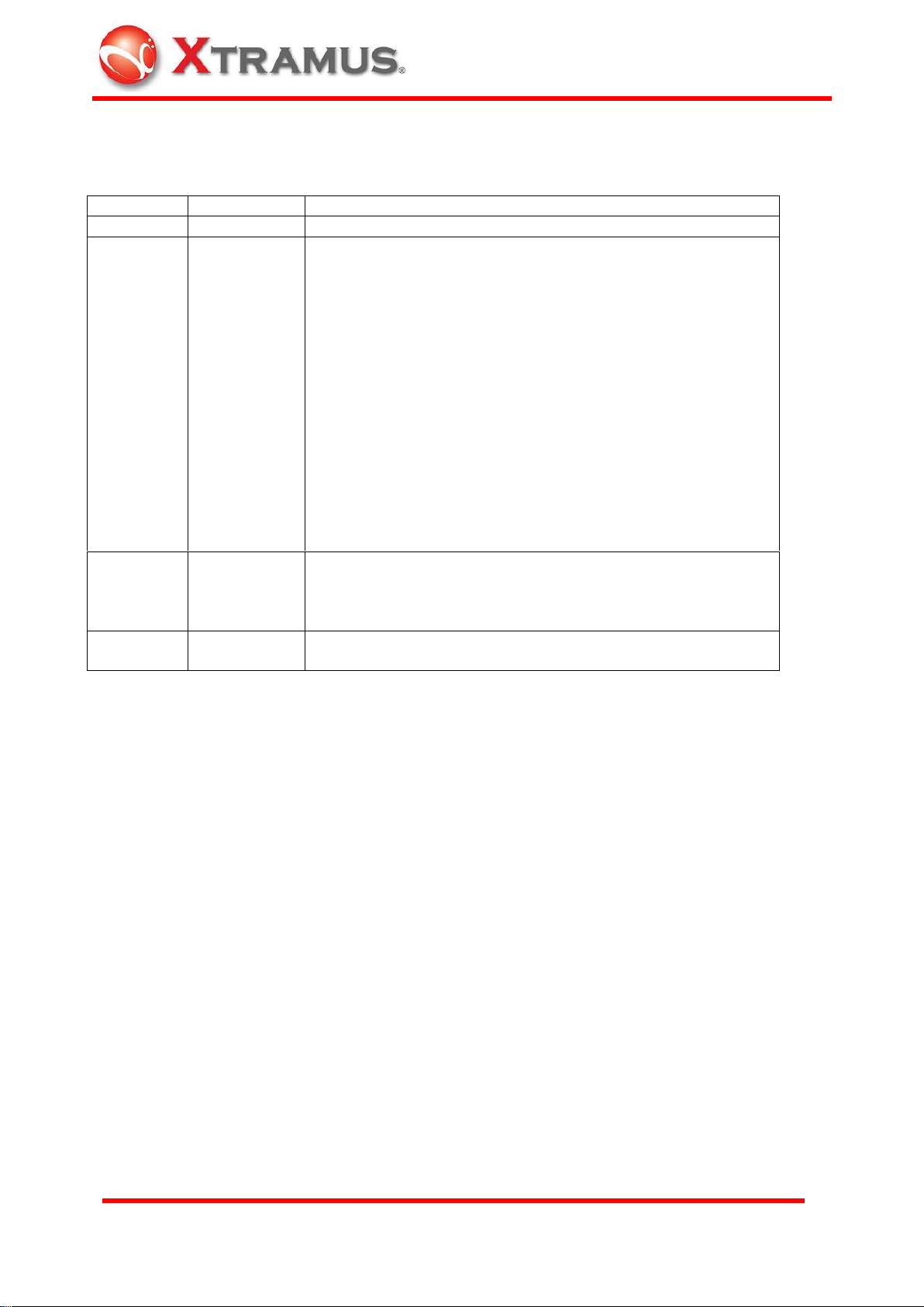
Date
USM Version
History
June, 2009
1.0
First release version
July, 2009
1.1
Icons of toolbar hotkeys are updated. Please refer to 5.3.2
Toolbar
For Packet Generation Test, the duration configured at
software is canceled. Only Time rotary switch on the body
of NuBAR-1000 can configure the duration. Please refe to
5.4.1.2 Default User Defined Function B: Packet
Generation Test
For user defined Loopback Test, the duration is configured
by rotary switch on the body of NuBAR-1000 only. Please
refer to 5.4.1.4 Default User Defined Function D: Loopback
Test
Auto or Force 10M Full duplex mode for all network
connection
Add caution to user that enough battery power is required
for large file download of Web Access test. Please refer to
5.4.1.3 Default User Defined Function C: Web Access
Sep. 2009
1.2
Add Open Log and Clear Log function in main menu.
Please refer to 5.3.1 Operation Menu
Add charge and operation time of battery. Please refer to
6.2.2 Charge and Operation Time of Battery
Aug. 2010
1.3
Changing format
Revise 6.3. Restriction of Operation
REVISION HISTORY
2
Page 4

E-mail: sales@xtramus.com
Website: www.Xtramus.com
XTRAMUS TECHNOLOGIES®
Table of Contents
Foreword ........................................................................................................................................ 1
REVISION HISTORY ...................................................................................................................... 2
Table of Contents .......................................................................................................................... 3
1. General Description of NuBAR-1000 .................................................................................... 4
2. Appearance ............................................................................................................................ 6
2.1 Front Side ...................................................................................................................... 6
2.2 Rear Side ....................................................................................................................... 6
2.3 Top Side and Bottom Side ............................................................................................ 9
2.4 Left side ....................................................................................................................... 10
2.5 Right Side .................................................................................................................... 11
3. Function of Rotary Switch and Buttons ............................................................................. 12
3.1 Rotary Switches for Configuration ............................................................................ 12
3.1.1 Rotary Function Switch .......................................................................................... 12
3.1.2 ID Rotary Switch ..................................................................................................... 17
3.1.3 Test Time Rotary Switch ........................................................................................ 18
3.2 Button for Operation ................................................................................................... 19
3.2.1 Run / Stop button ................................................................ ................................... 19
3.2.2 Clear Key ................................................................................................................. 20
3.2.3 Tx Test Key ............................................................................................................. 20
4. Procedure of Operation ....................................................................................................... 21
4.1 Hardware Connection ................................................................ ................................. 21
4.1.1 For Self-Test ............................................................................................................ 21
4.1.2 For Single DUT ....................................................................................................... 21
4.1.3 For Cable Wiring ..................................................................................................... 21
4.1.4 For Network Infrastructure .................................................................................... 22
4.1.5 For Mesh Network .................................................................................................. 22
4.1.6 For Loopback Test .................................................................................................. 23
4.1.7 For Broadcast Test ................................................................................................. 23
4.2 Test Procedure ............................................................................................................ 23
4.2.1 Configure the Function Mode ................................................................................ 23
4.2.2 Start the Test Procedure ........................................................................................ 24
4.3 Test Result ................................................................................................................... 25
5. Remote Control from USB Port .......................................................................................... 27
5.1 Installation of Driver ................................................................................................... 27
5.2 Installation of Software Utility .................................................................................... 28
5.3 Operation of Main Window ......................................................................................... 30
5.3.1 Operation Menu ...................................................................................................... 30
5.3.2 Toolbar .................................................................................................................... 34
5.4 Windows of Toolbar .................................................................................................... 35
5.4.1 Configuration .......................................................................................................... 35
5.4.2 Packet Generation .................................................................................................. 44
5.4.3 Symmetric Loop Test ............................................................................................. 47
5.4.4 Asymmetric Loop Test ........................................................................................... 50
6. Maintenance ......................................................................................................................... 52
6.1 Upgrade Firmware and FPGA .................................................................................... 52
6.2 Built-in Battery ............................................................................................................ 53
6.2.1 Replacement of Battery.......................................................................................... 53
6.2.2 Charge and Operation Time of Battery ................................................................. 53
6.3 Restriction of Operation ............................................................................................. 54
3
Page 5

E-mail: sales@xtramus.com
Website: www.Xtramus.com
XTRAMUS TECHNOLOGIES®
1. General Description of NuBAR-1000
NuBAR-1000 is an innovative compact network test
equipment in the market that constructs several
pioneering features that make on-site cabling and analysis
for network construction easy and efficient.
Network cabling for a new building or office is often done
by third party contractors. The technical personnel may
not care about the real throughput and most of contractor
only do the simple test by network cable tester to make
sure that cable are well arranged and connected. However, problems always happen when the
MIS start to deploy the network equipment inside the office. They may find that the cables are
either unable to reach the Wirespeed transmission or lots of error packets are received during
data transmission.
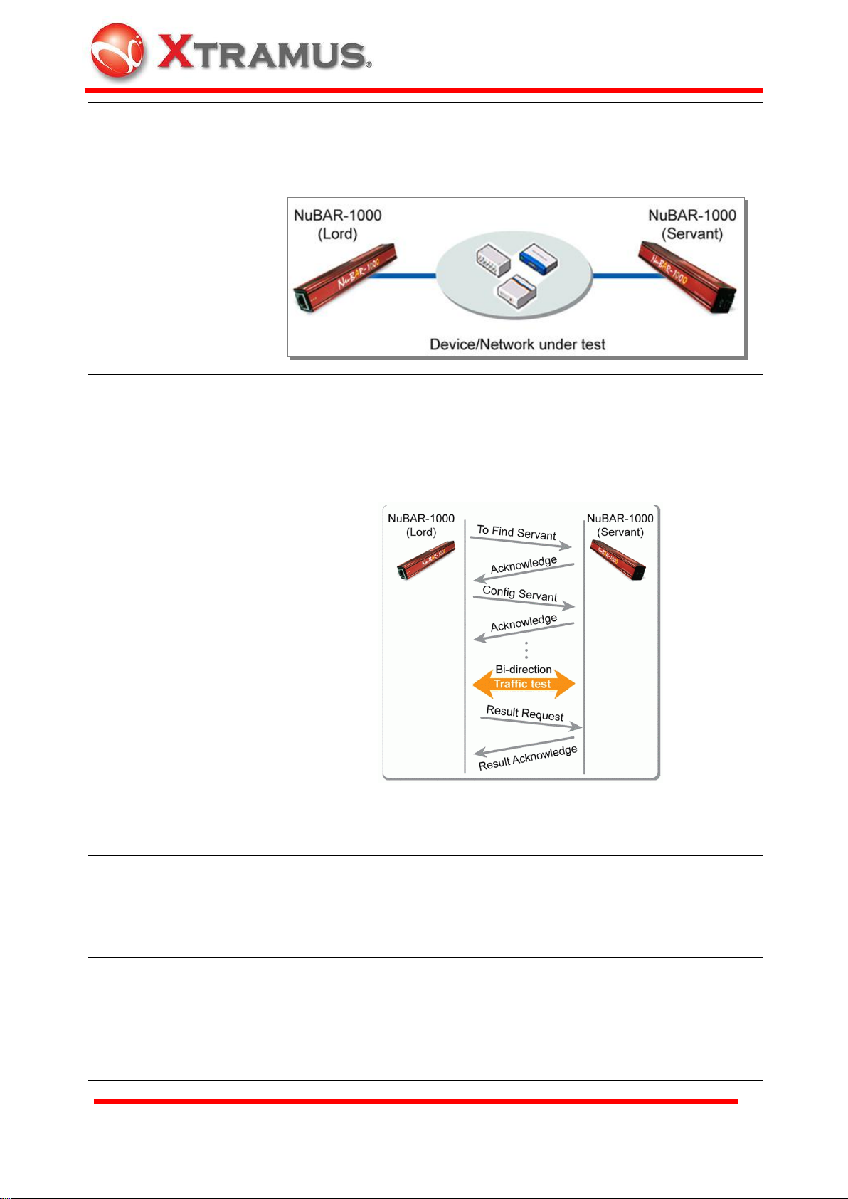
NuBAR-1000 is an ideal Ethernet tester for testing and troubleshooting potential problems of
data transmission and bandwidth in the field. NuBAR-1000 works by pair with roles of Lord and
Servant. Without extra standby personnel at the other test site, two NuBAR-1000 negotiate with
each other automatically, start bi-directional symmetric / asymmetric Wirespeed transmission,
synchronize the test result and store result at Lord NuBAR-1000.
For installation of asymmetric transmission network such as ADSL that downstream speed is
much faster than upstream speed, it is difficult to test the network by general loopback method
that data transmission speeds between two sides must be the same. Unique Asymmetric Loop
Test of NuBAR-1000 is able to do customized speeds asymmetric transmission test that can
verify the transmission quality of ADSL for ISP or Telecom Company.
With this affordable price and excellent functions for network probe and test on-site,
NuBAR-1000 is comprehensive solution for data transmission test in cable wiring phase or
troubleshooting phase in the field.
4
Page 6

E-mail: sales@xtramus.com
Website: www.Xtramus.com
XTRAMUS TECHNOLOGIES®
KEY FEATURES
Wirespeed gigabit packet generator and analyzer for bi-directional symmetric and
asymmetric transmission test
Packet generation of short, long and random length packet by on-panel operation
A pair of NuBAR-1000 that serve as Servant and Lord for Bi-directional or Loopback
transmission test.
Mesh Loop function test that forward test streams to up to five NuBAR-1000 in mesh LAN
Internet connectivity test by accessing and down file from internet.
Support Layer 1 and Layer 2 loopback
Five customized test modes on rotary switch that can be configured by PC in advance
and operated by on-panel button at test site
Time based test by rotary time switch or packet counts based test via configuration of
utility software
User-defined packet loss criteria for loopback test to determine Pass/Fail
Asymmetric network Test such as ADSL without complicate settings.
Powerful software application for advanced configuration/operation via USB cable
Built-in rechargeable battery. Conduct tests on-site without extra power source
KEY BENEFITS
Connect PC is not required for operation of test procedure.
Test product or network easily without specific expertise.
Compact and ultra light Gigabit Ethernet test device.
Built-in rechargeable NI-MH battery for testing of Ethernet anywhere.
10 pre-defined test patterns, and 5 user-defined patterns for instant testing or customized
application.
Test Ethernet network by two NuBAR-1000 that is located far away from each other.
Auto-negotiation along with bi-directional Symmetric/Asymmetric Wirespeed test or
loopback test to measure the network.
MAIN APPLICATIONS
Network Detecting in Research and Development
On-site test/repair/ maintenance of network in telecommunication and cable wiring
business
Network wiring task and trouble-shooting in office or building
Asymmetric transmission test such as ADSL
Test connection status of Internet
Solution of Last-mile test between CO (central office) and CPE (customer premises
equipment)
Integrated test solution for customized proposal.
5
Page 7
E-mail: sales@xtramus.com
Website: www.Xtramus.com
XTRAMUS TECHNOLOGIES®
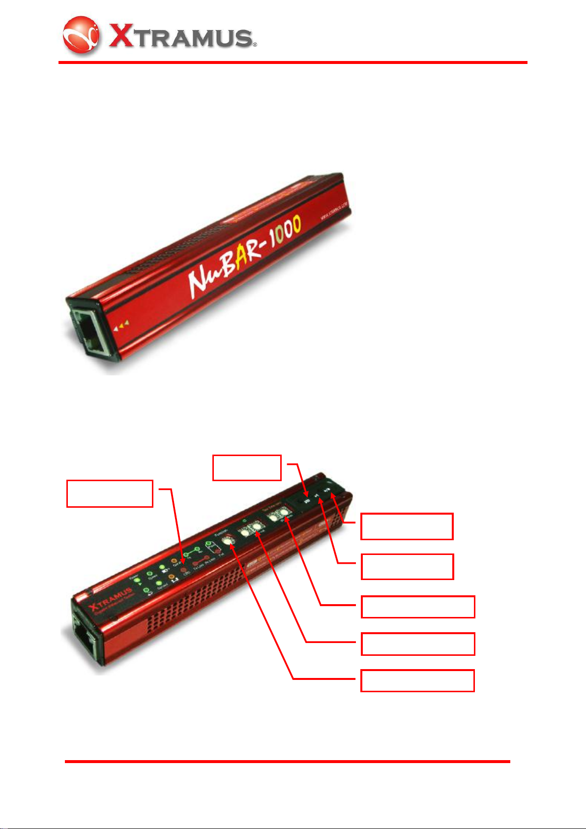
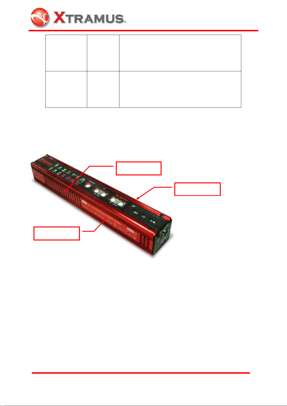
Status LED
Rotary ID Switch
Rotary Function Switch
Clear Key
Run / Stop Key
Tx Test Key
Rotary Test Time Switch
2. Appearance
2.1 Front Side
There is a model name of this device.
2.2 Rear Side
Operation buttons and LED indicators are located here.
6
Page 8
E-mail: sales@xtramus.com
Website: www.Xtramus.com
XTRAMUS TECHNOLOGIES®
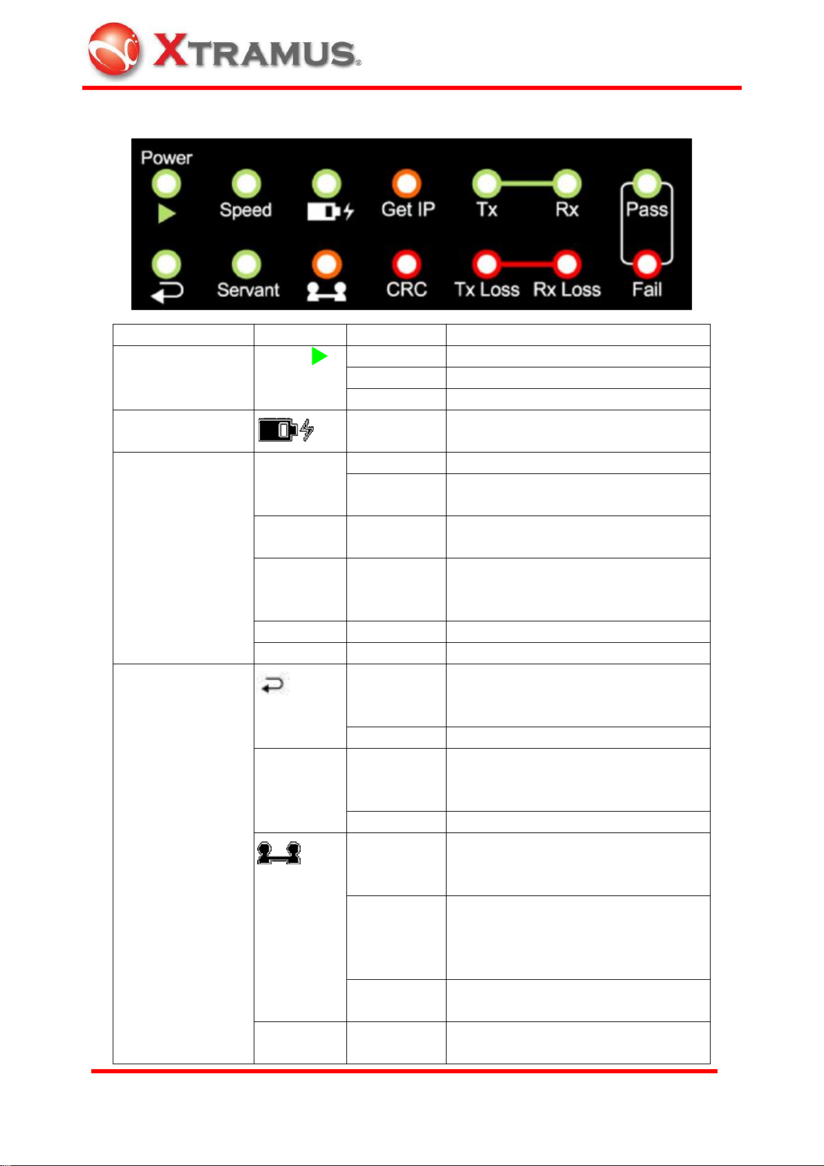
Type
Label
LED
Description
System
Power
(Run)
ON
System is ready
Blinking
System is running the specified task
OFF
Power is off
Battery
ON
Battery is almost exhausted. Please
connect USB cable to charge it.
Test result
CRC
ON
CRC Error is found during the test
Blinking
Keep blinking if CRC error packets are
received continually.
Tx loss
ON
Packet loss is found from local to
remote side during the test.
Rx loss
ON
Packet loss is found at receiving side
from remote to local side during the
test.
Fail
ON
Result of the test is failed.
Pass
ON
Result of the test is passed.
Functional Status
(Loopback)
ON
Loopback status is enabled. Rotate
functional rotary switch to 8 or 9 mode
to enable this status
OFF
Under normal Lord or Servant mode.
Servant
ON
This device is under Servant Mode.
Rotate functional rotary switch to this
mode.
OFF
This device is under Lord Mode.
(Connect)
ON
Negotiation and connection between
Lord unit and Servant unit is
successful.
Slow blinking
(1Hz)
Request connection to Lord unit or
Servant unit. If the unit is under Lord
mode, then it request connection to
Servant, and vice versa.
Fast blinking
(8Hz)
Request connection between Lord unit
and Servant unit is failed.
Get IP
ON
Test the connection to Internet is
successful.
Status LED
7
Page 9
E-mail: sales@xtramus.com
Website: www.Xtramus.com
XTRAMUS TECHNOLOGIES®
Slow blinking
(1Hz)
Try to get an IP address from DHCP
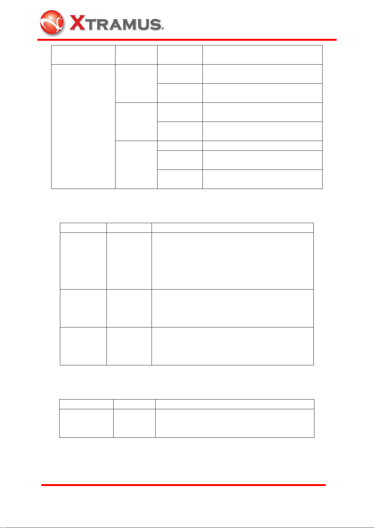
Transmission Status
TX
Slow blinking
(2Hz)
Data is transmitting
Fast blinking
(4Hz)
Transmitting in Wirespeed
RX
Slow blinking
(2Hz)
Data is receiving
Fast blinking
(4Hz)
Receiving in Wirespeed
Speed
ON
1000Mbps connection
Mild blinking
(2Hz)
100Mbps connection
Slow blinking
(1Hz)
10Mbps connection
Label
Scale
Description
Function
1 set
16 scales
0~9, A~F
16 function modes
0~9: Pre-defined function
A~E: Customized settings
F: Control by PC via mini-USB port of NuBAR-1000.
For detail, please refer to 3.1.1 Rotary Function
Switch
ID
2 sets
16 scales
0~9, A~F
Pair mapping control of NuBAR-1000 if there are
more then one pair of NuBAR-1000 connected in
the same network.
For detail, please refer to 3.1.2 ID Rotary Switch
Test Time
(sec)
2 sets
16 scales
0~9, A~F
It is for the configuration of test duration each time.
Duration in seconds is configured in hex mode.
For detail, please refer to 3.1.3 Test Time Rotary
Switch
Label
Action
Description
►/■
Push once
Run / Stop Key
Press it to start or stop the procedure configured in
Rotary Function Switch.
Rotary Switch
Buttons
8
Page 10
E-mail: sales@xtramus.com
Website: www.Xtramus.com
XTRAMUS TECHNOLOGIES®
►t
Push once
Tx Test Key
Transmit 10 broadcast short packet by 2 different
MAC address. One MAC address is for the
transmission of management parameter and the
other is for the test packets.
000
Push once
Clear Key
Clear the test result for next test. When test is
done, all LEDs keep the result of pervious test.
Press this key to clear all test results, then operator
is able to process next test.
Ventilation Hole
Instruction Label
Serial No. Label
2.3 Top Side and Bottom Side
Ventilation hole, instruction label for rotary function key and Serial No. label are located here.
9
Page 11
E-mail: sales@xtramus.com
Website: www.Xtramus.com
XTRAMUS TECHNOLOGIES®
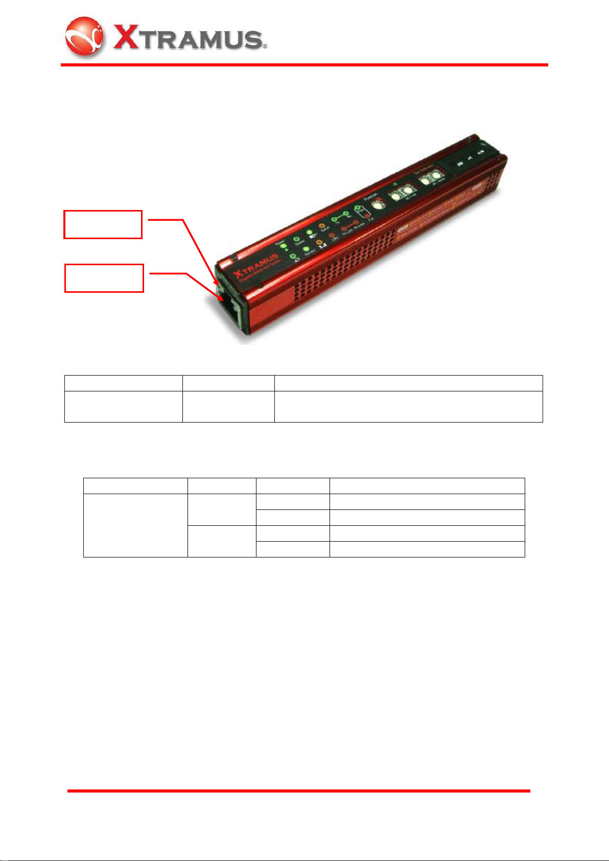
Port Type
Label
Description
UTP Ethernet port for
RJ-45 connector
10 100 1000M
Ethernet port for 10/100/1000M speed connection
of RJ-45 connector
Type
Label
LED
Description
UTP Port status for
RJ-45 connector
Link/ACT
ON
Network is linked up.
Blinking
Data is transmitting or receiving
Full
ON
Full duplex connection
OFF
Half duplex connection
UTP Port
Status LED
2.4 Left side
Left side has UTP ports that connect with physical transmission media.
Connection Ports
Status LED
10
Page 12
E-mail: sales@xtramus.com
Website: www.Xtramus.com
XTRAMUS TECHNOLOGIES®
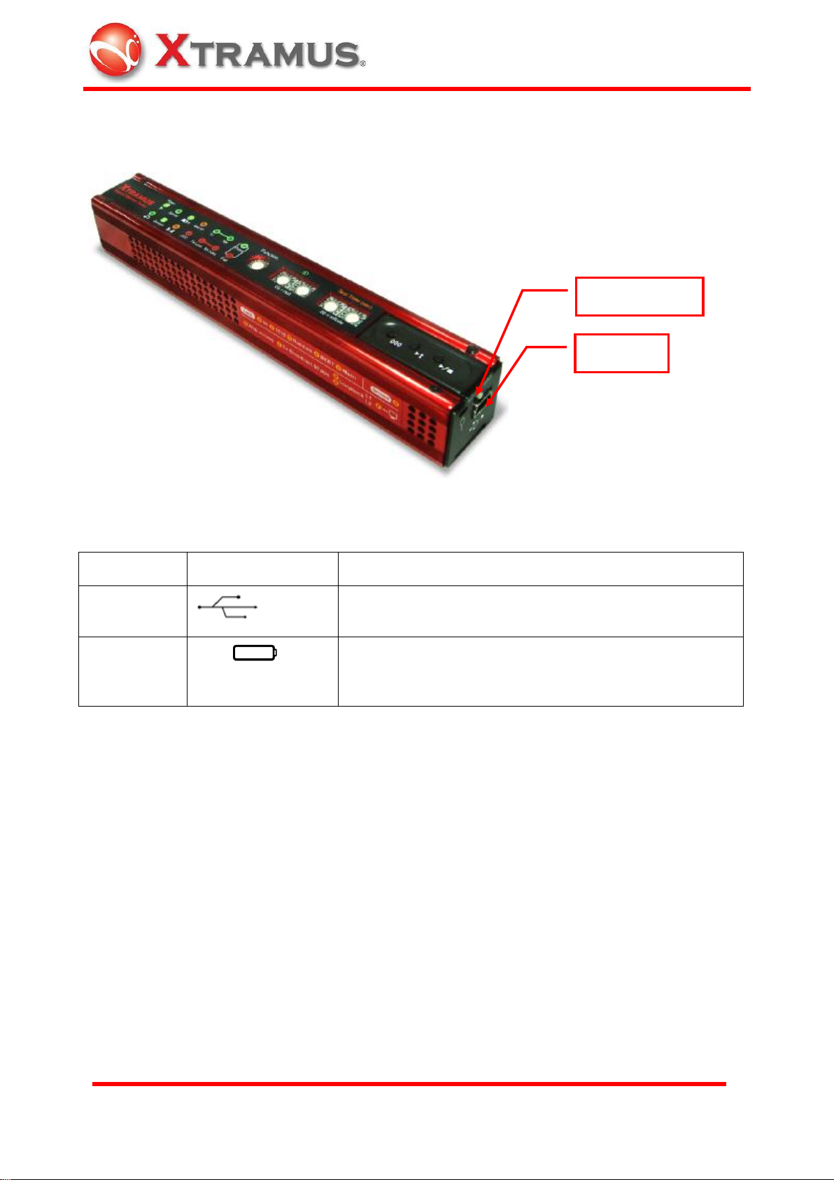
Type
Label
Description
Mini-USB
Power supply, battery charge, remote control and
configuration or Firmware/FPGA upgrade of this machine
Power
Switch
OFF ON
Turn on or turn off the operation of NuBAR-1000.
Powered USB cable keep charging the battery of
NuBAR-1000 even though the power switch is OFF.
Mini-USB
Power Switch
2.5 Right Side
Connection Ports
11
Page 13
E-mail: sales@xtramus.com
Website: www.Xtramus.com
XTRAMUS TECHNOLOGIES®
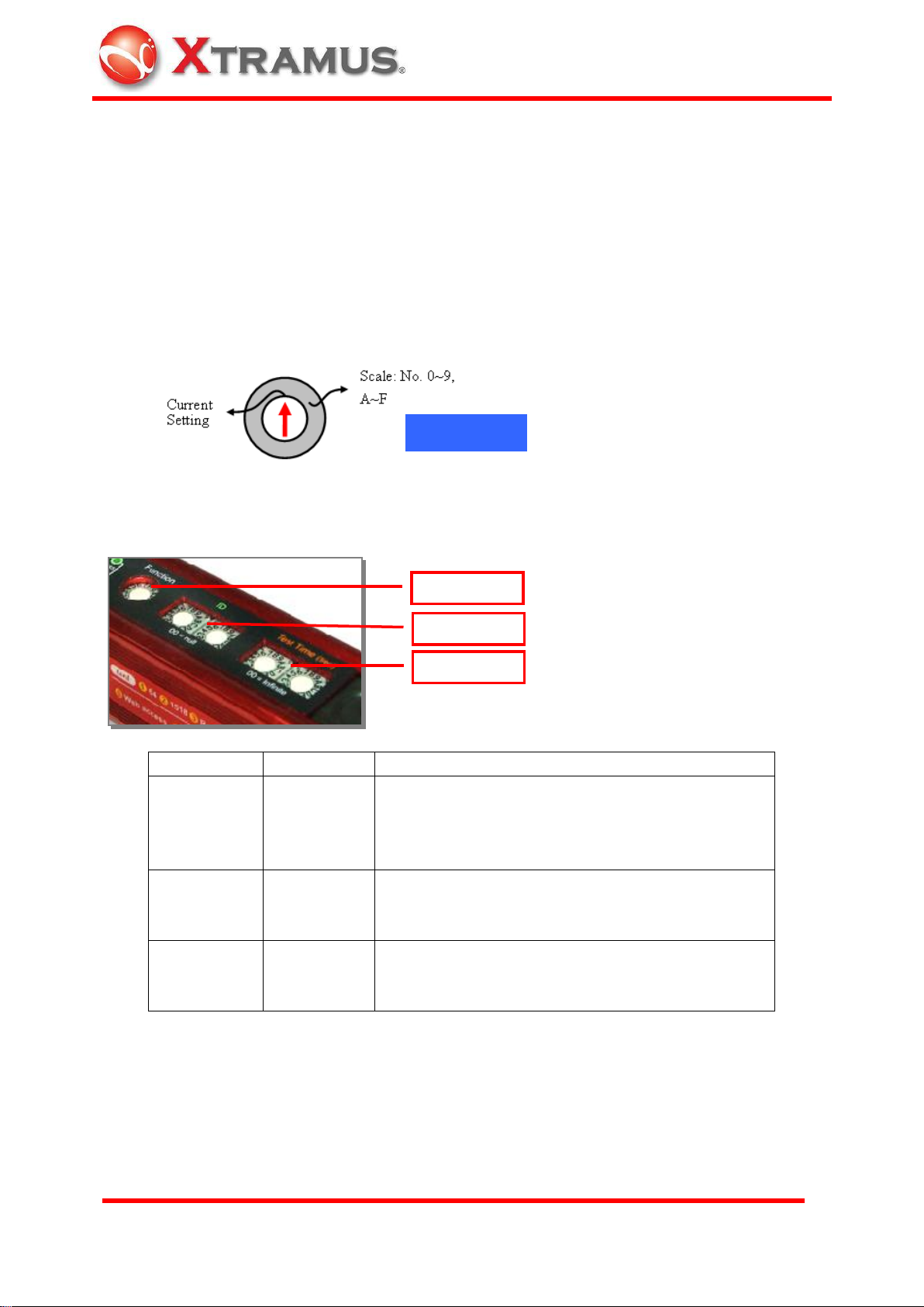
Label
Scale
Description
Function
1 set
16 scales
0~9, A~F
16 function modes
0~9: Pre-defined function
A~E: Customized settings
F: Control by PC via USB port.
ID
2 sets
16 scales
0~9, A~F
Pair mapping control of NuBAR-1000 if there are
more then one pair of NuBAR-1000 connected in
the same network.
Test Time
(sec)
2 sets
16 scales
0~9, A~F
It is for the configuration of test duration each time.
Duration in seconds is configured in hex mode.
Rotary Switch
Function
ID
Test Time
3. Function of Rotary Switch and Buttons
At the bottom of this machine, there are rotary switches and buttons for almost all operation of
this machine. Rotary switches are for the configuration of this machine and buttons are for the
operation of this machine.
3.1 Rotary Switches for Configuration
There are several 16 scales rotary switches, scales from 0 to 9, A to F for 16 functions.
Use ceramics screwdriver that comes with NuBAR-1000 package to rotate this switch for the
function below:
As the description at few sections above, the table is the general description of rotary switch
3.1.1 Rotary Function Switch
There is one 16 scales Functional Rotary Switch for 16 functions
12
Page 14
E-mail: sales@xtramus.com
Website: www.Xtramus.com
XTRAMUS TECHNOLOGIES®
Scale
Function name
Description
0
Servant mode
Switch to Servant mode and accepts control and test from Lord.
LED of Servant is ON when this mode is activated.
1
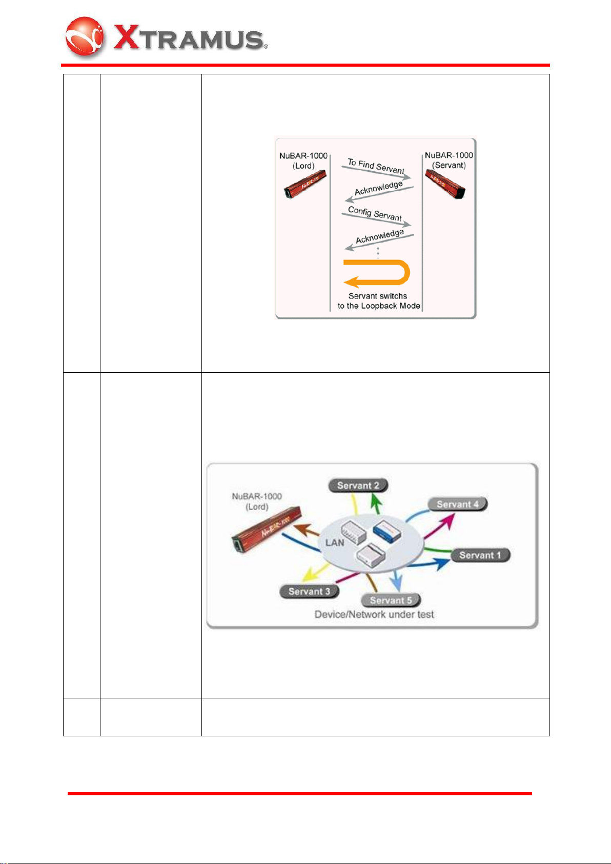
Short Packet Test
Lord requests Servant for symmetrical and bi-directional Wirespeed
short packets (64 bytes) test. Lord and Servant do negotiation first,
start test, synchronize result with each other, and then show test
result when test is done. Pass LED is ON if no CRC errors, packet
loss errors and other errors are found, otherwise, it is failed.
Rotary function switch location
Lord NuBAR-1000: 1
Servant NuBAR-1000: 0
2
Long Packet Test
Same test as function 1 with long packets length (1518 bytes).
Rotary function switch location
Lord NuBAR-1000: 2
Servant NuBAR-1000: 0
3
Random Packet
Test
Same test as function 1 with random length packets (64~1518
bytes).
Rotary function switch location
Lord NuBAR-1000: 3
Servant NuBAR-1000: 0
13
Page 15
E-mail: sales@xtramus.com
Website: www.Xtramus.com
XTRAMUS TECHNOLOGIES®
4
BERT Loopback
Test
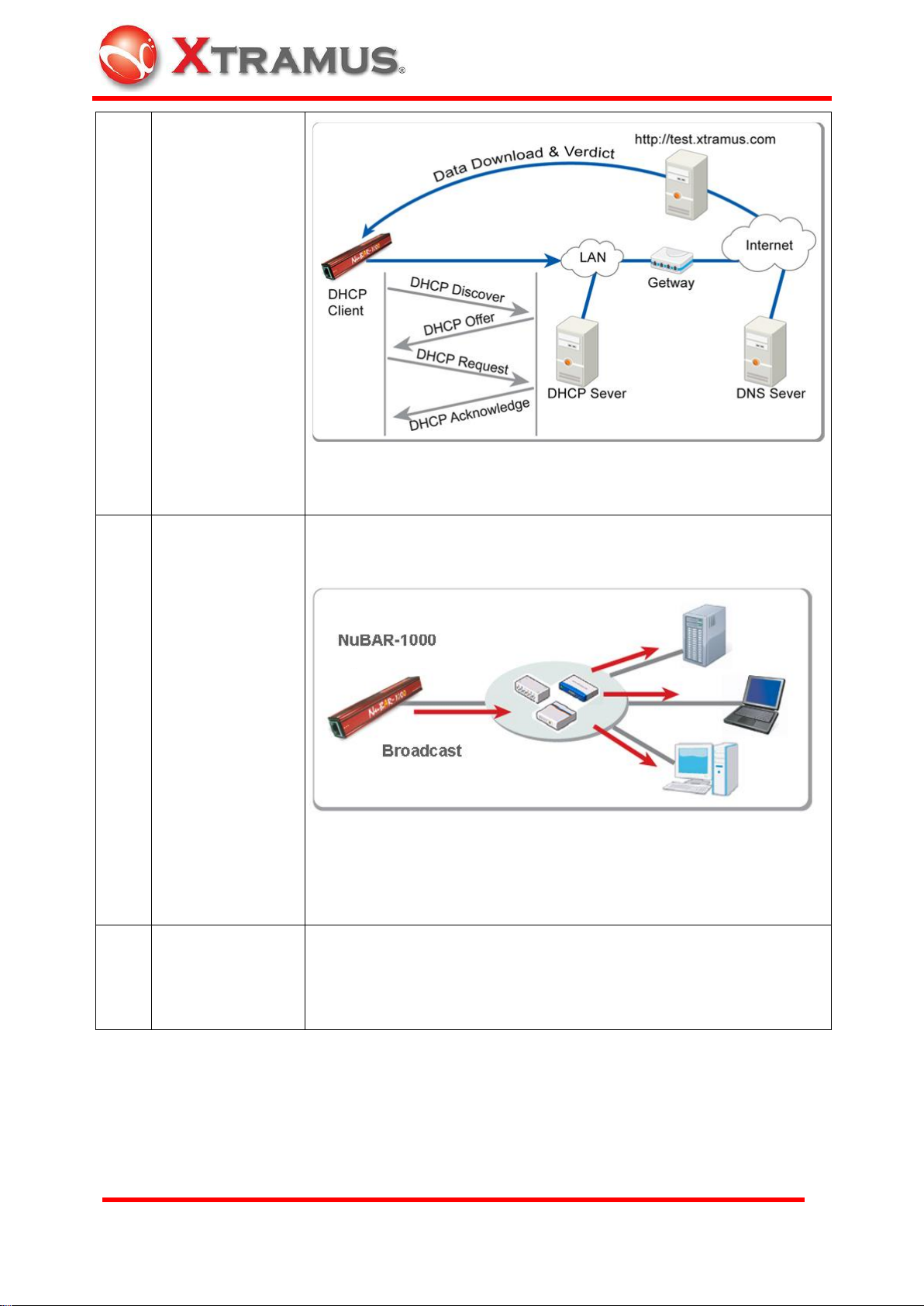
Lord sends BERT (Bit Error Rate Test) pattern (long packets, PRBS
2^31-1) to Servant and returns with switched DA / SA (destination /
source MAC address) and recalculated CRC for Loopback test.
Rotary function switch location
Lord NuBAR-1000: 4
Servant NuBAR-1000: 0
5
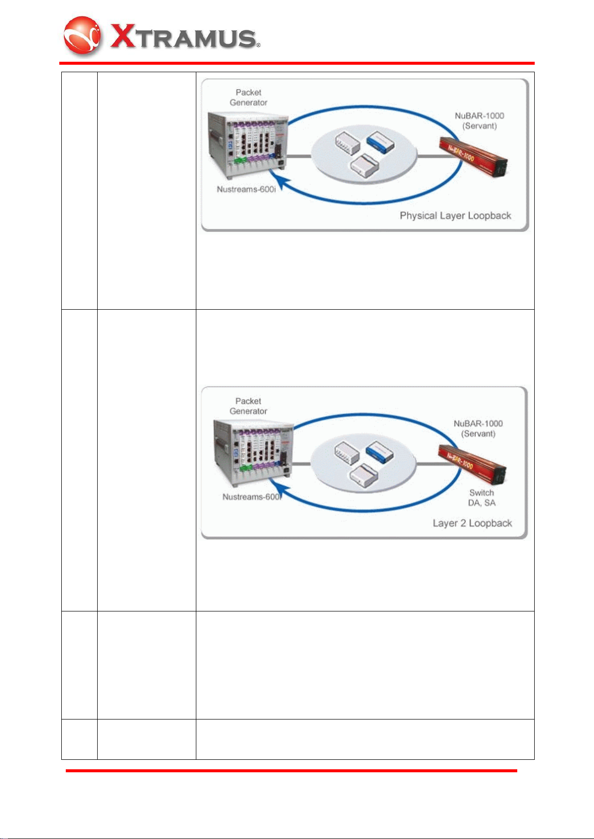
Mesh Loop Test
Lord send mesh connection request to all Servants. There are
maximum 5 Servants for this mesh connection test.
Then Lord sends test packets to the 1st Servant, then the 1st Servant
forward packets to 2nd Servant. Procedure is repeated until the final
Servant returns packets to Lord.
When test is done, all of them synchronize the result.
Rotary function switch location
Lord NuBAR-1000: 5
Servant NuBAR-1000: 0. The sequnece of acknowledge from
servants decides the sequence of servant.
6
Web Access
Get IP from DHCP server in the LAN and then access web server in
Internet to download a specified file from Internet for test purpose.
14
Page 16
E-mail: sales@xtramus.com
Website: www.Xtramus.com
XTRAMUS TECHNOLOGIES®
Rotary function switch location
NuBAR-1000: 6
7
Transmit
Broadcast Packet
60pps
Send broadcast packets 60 times per second with increasing packet
length (64~1518, 64...).
There is no test result and termination for the test.
Rotary function switch location
NuBAR-1000: 7
8
Loopback Slave
(layer1)
This mode is test for other non-NuBAR-1000 device (Packet
Generator). NuBAR-1000 resend incoming test frames from other
non-NuBAR-1000 device to its received port.
15
Page 17
E-mail: sales@xtramus.com
Website: www.Xtramus.com
XTRAMUS TECHNOLOGIES®
There is no test result and termination for the test.
Rotary function switch location
Servant NuBAR-1000: 8
9
Loopback Slave
(layer2)
This mode is test for other non-NuBAR-1000 device (Packet
Generator). NuBAR-1000 resend incoming test frames from other
non-NuBAR-1000 device to its received port with switched DA / SA
(destination / source MAC address) and recalculated CRC.
There is no test result and termination for the test.
Rotary function switch location
Servant NuBAR-1000: 9
A~E
Customized
settings
Customized test settings that can be configured by PC via USB port.
There are pre-configured default settings for other test. Please refer
to
Rotary function switch location
Lord NuBAR-1000: A~E
Servant NuBAR-1000: 0
F
PC control
Remote control, configuration and firmware/FPGA update by
NuBAR-WIN application software via USB port.
16
Page 18

E-mail: sales@xtramus.com
Website: www.Xtramus.com
XTRAMUS TECHNOLOGIES®
Note: NuBAR-1000 can be charged by PC or external power
adaptor in any Function Modes.
Rotary function switch location
Lord NuBAR-1000: F
Servant NuBAR-1000: Accepts control from Lord NuBAR-1000. Set
it to Servant mode and configuration is not required.
Scale: No. 0~9,
A~F
Current
Setting
Scale: No. 0~9,
A~F
16 x 16 = 256
ID number
3.1.2 ID Rotary Switch
There are two 16 scales ID Rotary Switch for mapping of Lord and Servant
NuBAR-1000 with the same ID, which the two ID rotary switches are identical the same,
works as a pair (Lord and Servant)
If the mapping duration exceeds 20 seconds without successful connection, the connection
procedure is suspended.
Set it to "0", means Lord accepts any reply from Servant if NuBAR-1000 is in Lord mode.
Set it to "0", means Servant replies any request from Lord if NuBAR-1000 is in Servant mode.
Unless switching the rotary switch for a pair of NuBAR-1000 to different ID, the pair of
NuBAR-1000 keeps working together even though there is a new added NuBAR-1000 with
the same ID exists in the same network.
Lord and Servant works as pair that is based on MAC address. One NuBAR-1000 uses 2
17
Page 19

E-mail: sales@xtramus.com
Website: www.Xtramus.com
XTRAMUS TECHNOLOGIES®
Scale: No. 0~9,
A~F
Current
Setting
Scale: No. 0~9,
A~F
16 x 16 = 256
Seconds (maximum)
MAC address, one is for transmission of test data and the other is for negotiation and
communication. DUT/NUT has to register totally 4 MAC addresses in its MAC address table
for a pair of NuBAR-1000.
3.1.3 Test Time Rotary Switch
There are two 16 scales Test Time Rotary Switch for configuration of duration for each test.
It is for the configuration of test duration each time. Duration in seconds is configured in 2 hex
mode rotary switches.
16 scales rotary switch: 0~9, A = 10, B = 11. C = 12, D = 13, E=14, F=15
User can calculate the result from Windows calculator (Start Programs Accessories
Calculator). For example, 12 seconds
Input 12 in Decimal mode
Then click Hexadecimal, then the answer is C. Rotate the switch to "0" "C" for duration of 12
seconds
18
Page 20

E-mail: sales@xtramus.com
Website: www.Xtramus.com
XTRAMUS TECHNOLOGIES®
Clear
Tx Test
Run / Stop
When user clicks Start / Run button to start the test, the NuBAR-1000 stops automatically for a
moment later, owing to the test duration configured here. If test duration is configured, wait result
until the test is done. Press Stop button to stop the test immediately will cause a fail test.
If it is configured to "0", the test keeps going continually, unless user press Stop button to stop
the test.
3.2 Button for Operation
There are 3 buttons for the operation of NuBAR-1000. When configuration via rotary switch is
done, press these buttons to operate the function for the test.
3.2.1 Run / Stop button
Press it to start the procedure configured in Rotary Function Switch. The procedure will stop
automatically, owing to the internal settings of the procedure or the duration configured at Rotary
Test Duration Switch.
Force to stop the procedure by pressing it again. For most of test procedures, they will stop
automatically. Force to stop these tests probably cause failed result.
19
Page 21

E-mail: sales@xtramus.com
Website: www.Xtramus.com
XTRAMUS TECHNOLOGIES®
3.2.2 Clear Key
Clear the current test result for next test. When test is done, all LEDs keep the result of pervious
test. Press this key to clear all test results, then operator is able to process next test.
3.2.3 Tx Test Key
Transmit 10 broadcast short packets by 2 different MAC address One MAC address is for the
transmission of management parameter and the other MAC address is for the test packets.
20
Page 22

E-mail: sales@xtramus.com
Website: www.Xtramus.com
XTRAMUS TECHNOLOGIES®
Servant
Lord
Cat. 5e or above
network cable
Lord
Servant
4. Procedure of Operation
This chapter tells user how to use NuBAR-1000 in your test site.
4.1 Hardware Connection
4.1.1 For Self-Test
Before the real test, operator can connect the two devices directly by network cable (Cat. 5e or
above is suggested) for functional check.
4.1.2 For Single DUT
Without high cost desktop test equipment, the compact size NuBAR-1000 is able to do Ethernet
network test easily.
The test streams run through the two ports that join the test. If there are more than two port that
need to join the test simultaneously, other advanced model can fit user's requirement. Please
contact with distributor of Xtramus.
4.1.3 For Cable Wiring
To wiring a network cable in office or building, NuBAR-1000 is convenient for data transmission
test. Do this test to insure the transmission quality for real environment. To test the cable inside
the building, connect two sides of the cable to a pair of NuBAR-1000. If the test is passed, it also
performs well in real condition by real network device.
21
Page 23

E-mail: sales@xtramus.com
Website: www.Xtramus.com
XTRAMUS TECHNOLOGIES®
A
B
4.1.4 For Network Infrastructure
To test the transmission quality between two network locations that is connected by multiple
network equipments such as Ethernet Switches, Network Server, connect two ends of the
network device to a pair of NuBAR-1000. The figure below illustrates the transmission test
between location A and B.
Note: NuBAR-1000 is test equipment of layer 2 packet. Devices that can not forward layer 2
(MAC based) packet are not suitable for the test. Network such as Internet runs layer 3 protocols
is not suitable for the test. It is applicable for ADSL test for cable wiring business. The connection
between CO (central office) and the CPE (ADSL modem) apply layer 2 Ethernet.
4.1.5 For Mesh Network
As the rotary function switch introduced above, NuBAR-1000 is able to do mesh connection test.
Lord sends test packets to the 1st Servant, then the 1st Servant forward packets to 2nd Servant.
Repeat the procedure until the packets returns to Lord finally.
The application below applies to six locations of network infrastructure.
22
Page 24

E-mail: sales@xtramus.com
Website: www.Xtramus.com
XTRAMUS TECHNOLOGIES®
Servant
Lord
Servant
Lord
Analyzer
Packet Generator
1
0
4.1.6 For Loopback Test
The Loopback test for NuBAR-1000 can be divided into 2 kinds. One is the loopback test by a
pair of NuBAR-1000 and the other is loopback test with other network device (packet generator).
By a pair of NuBAR-1000
Work with other network device (packet generator)
4.1.7 For Broadcast Test
There is no test result for broadcast test. Operator can install other network analyzer to monitor
or count the broadcast packets for test purpose.
4.2 Test Procedure
4.2.1 Configure the Function Mode
Select function mode
To use the NuBAR-1000, select the test mode what you need. Please refer to 3.1.1 Rotary
Function Switch
To do the test by pair, the rotary function switch for Lord and Servant is different.
For short packet test
Lord NuBAR-1000 Servant NuBAR-1000
23
Page 25

E-mail: sales@xtramus.com
Website: www.Xtramus.com
XTRAMUS TECHNOLOGIES®
0 1 0
1
3
C
Configuration for
Servant NuBAR-1000
is not required
Turn On
Select the same ID for a pair of NuBAR-1000
For a test that is work by a pair of NuBAR-1000, the ID number of the two NuBAR-1000 has to
be the same. The default ID of NuBAR-1000 is "00". , means Lord accepts any reply from
Servant if NuBAR-1000 is in Lord mode and Servant replies any request from Lord if
NuBAR-1000 is in Servant mode.
Rotate two ID rotary switches to other value, such as "01" for two NuBAR-1000.
Lord NuBAR-1000 Servant NuBAR-1000
Configure the test duration for a single test
Test duration is configured by hexadecimal mode that is described at 3.1.3 Test Time Rotary
Switch
For 1 minutes (60 seconds) test
Lord NuBAR-1000 Servant NuBAR-1000
4.2.2 Start the Test Procedure
Power ON both Lord and Servant NuBAR-1000 from power switch.
Note: To fit the compact size of the NuBAR-1000, the power switch is tiny. To prevent damage of
this switch, please slide the switch carefully or push it via the attached ceramic screwdriver.
24
Page 26

E-mail: sales@xtramus.com
Website: www.Xtramus.com
XTRAMUS TECHNOLOGIES®
Type
Label
LED
Description
Test result
CRC
ON
CRC Error is found during the test
Blinking
Keep blinking if CRC error packets are
received continually.
Tx loss
ON
Packet loss is found when test stream
is transmitted from local side to
remote side during the test
Rx loss
ON
Packet loss is found when test stream
is received from remote side to local
side during the test.
Fail
ON
Result of the test is failed.
Check the system status before starting test.
In normal condition, Power, Servant is ON and Battery is blinking if charging is processing.
Note: To operate different function mode via Functional Rotary Switch, the role of NuBAR-1000
become Lord. Then the Servant LED is OFF and Lord mode is activated.
Connect hardware with network cable
Connect the network cable depending on the different test scenario as described in 4.1
Hardware Connection
Connect a pair of NuBAR-1000
Press the Tx Test button to test the network. Speed is ON (ON: 1000Mbps connection; Mild
blinking (2Hz): 100Mbps connection; Slow blinking (1Hz): 10Mbps connection)
Start Test
Press the Run / Stop button to start the test, (connect) is ON and wait for the stop
automatically.
4.3 Test Result
The result of the test is shown on the LED indicator instantly.
25
Page 27

E-mail: sales@xtramus.com
Website: www.Xtramus.com
XTRAMUS TECHNOLOGIES®
Pass
ON
Result of the test is passed.
Detail result and counter can be knows via the NuBAR-WIN application software. Please refer to
5 Remote Control from USB Port
26
Page 28

E-mail: sales@xtramus.com
Website: www.Xtramus.com
XTRAMUS TECHNOLOGIES®
Basic System Requirement for NuBAR-1000 application software
Windows XP
Windows Vista
CPU
800MHz CPU
1.6 GHz, 32 bits (x86) CPU
RAM
256MB RAM
1GB RAM
HDD
20MB available space
(available space means the space for
installation and operation)
20MB available space
(available space means the space for
installation and operation)
Mini-USB Port
1. Install driver
2. Run Utility software
3. Configuration and control this
device
USB Port of PC
5. Remote Control from USB Port
NuBAR-1000 series come with a Windows GUI (graphic user interface) application software,
NuBAR-WIN that is running at PC for controlling of this machine. Operator can operate this
machine via USB port, collect statistic counter and do system upgrade.
USB cable with mini-USB connector comes with the package of this machine. If operator does
not have this cable, it is possible to purchase it from local electronic store. It is an industrial
standard cable with standard male USB connector and standard male mini-USB connector at
each side.
5.1 Installation of Driver
To active the USB connection, install driver for NuBAR-1000 series is required
The procedure below shows the installation of driver
1. Power On the machine
2. Connect USB cable to both PC and mini-USB port of NuBAR-1000
3. Windows will prompt you that new USB device is found and it needs driver. Manual select the
driver location at the folder ..\NuBAR-1000 driver which operator gets it from Xtramus.
Follow the instruction of Windows to finish the installation.
4. If driver is installed correctly, when you click icon at right-bottom corner of Windows task
27
Page 29

E-mail: sales@xtramus.com
Website: www.Xtramus.com
XTRAMUS TECHNOLOGIES®
Windows UI
Description
Welcome to install NuBAR-1000 Utility.
Please click Next button to continue
License Agreement for End User. Click I
accept the terms in the license
agreement, and then click Next
NuBAR-1000
bar, it shows NuBAR-1000 device
5.2 Installation of Software Utility
Click to run the .EXE utility execution file provided by Xtramus to install the software. System
shows
28
Page 30

E-mail: sales@xtramus.com
Website: www.Xtramus.com
XTRAMUS TECHNOLOGIES®
Input User Name and Organization and
click Anyone who uses this computer
(all users) and Next
Confirm the message for installation.
Click Install to start installation
procedure
Click Finish to close the installation
procedure
When Installation is done, start the program by clicking Start All Programs Xtramus
NuBAR-1000 NuBAR-WIN vx.xxxxx NuBAR-WIN vx.xxxxx (x is version number) or
at desktop, then main windows is shown.
29
Page 31

E-mail: sales@xtramus.com
Website: www.Xtramus.com
XTRAMUS TECHNOLOGIES®
Menu Choice
Usage
Load Default Config
Load default setting and clear all configurations that is done by
users.
Load Config
Select folder, filename and load configuration file that is saved
previously. The configuration is classified as the categories below.
B
C
D
5.3 Operation of Main Window
The block A, B, C, D is used for the successive sections. For the detail of each block, please
read the sections below.
5.3.1 Operation Menu
Block in main window: A
File sub-menu Program Files Xtramus NuBAR-1000\ NuBAR-WIN vx.xxxxx\TestLog
30
Page 32

E-mail: sales@xtramus.com
Website: www.Xtramus.com
XTRAMUS TECHNOLOGIES®
Packet Generation Test
Load configuration file of Packet Generation Test. For Packet
Generation Test, please refer to 5.4.2 Packet Generation
Symmetric Loop Test
Load configuration file of Symmetric Loop Test. For Symmetric
Loop Test, please refer to 5.4.3 Symmetric Loop Test
Asymmetric Loop Test
Load configuration file of Asymmetric Loop Test. For
Asymmetric Loop Test, please refer to 5.4.4 Asymmetric Loop
Test
User Defined Function A
Load configuration file of User Defined Function A. For User
Defined Function A~E, please refer to 5.4.1 Configuration
User Defined Function B~E is same as above
Save Config
Select folder, save configuration filename in specified folder. The
configuration file is classified as the categories below.
Packet Generation Test
Save configuration file of Packet Generation Test. Default
folder is located at
C:\Program Files\Xtramus\NuBAR-1000\NuBAR-WIN
Vx.xx...\Config\PGTest
Symmetric Loop Test
Save configuration file of Symmetric Loop Test. Default folder is
located at
31
Page 33

E-mail: sales@xtramus.com
Website: www.Xtramus.com
XTRAMUS TECHNOLOGIES®
C:\Program Files\Xtramus\NuBAR-1000\NuBAR-WIN
Vx.xx...\Config\SymLoopTest
Asymmetric Loop Test
Save configuration file of Asymmetric Loop Test. Default folder
is located at
C:\Program Files\Xtramus\NuBAR-1000\NuBAR-WIN
Vx.xx...\Config\AsyLoopTest
User Defined Function A
Save configuration file of User Defined Function A. Default
folder is located at
C:\Program Files\Xtramus\NuBAR-1000\NuBAR-WIN
Vx.xx...\Config\UDF_A
User Defined Function B~E is same as above that the folder
name is UDF_B ~ UDF_E
Load Log
Load test logs from built-in memory of NuBAR-1000. These test
logs is saved for test without PC.
Open Log
Open the saved logs that is loaded from NuBAR-1000
Clear Log
Clear the logs in the built-in memory of NuBAR-1000. System will
prompt you before clearing the log.
Exit
Exit and close this utility
Menu Choice
Usage
System Upgrade
Do system upgrade for
Firmware: Firmware in NuBAR-1000 device.
Select file from folder and click download button.
Service sub-menu
32
Page 34

E-mail: sales@xtramus.com
Website: www.Xtramus.com
XTRAMUS TECHNOLOGIES®
FPGA: (Field Programmable Gate Array) chip in NuBAR-1000 device
Select file from folder and click download button.
Menu Choice
Usage
About
System information, such as Utility version and Hardware version of
NuBAR-1000 device
Help sub-menu
33
Page 35

E-mail: sales@xtramus.com
Website: www.Xtramus.com
XTRAMUS TECHNOLOGIES®
Help
Open user manual or other help information.
Keys
Usage
E: Configuration
Click it to Show System information at C block and all
illustration graph or configurable items at D block. Click its sub
tree in C to enter the window of detail configuration.
F: Packet Generation
Configure packet generation parameter. The destination can
be a specified MAC, broadcast or the NuBAR-1000 itself.
G: Symmetric Loop Test
Configure symmetrical and bi-directional loop test. It has to
work by a pair of NuBAR-1000. The test is suitable for LAN
network test.
E F G H
C
D
5.3.2 Toolbar
Block in main window: B
34
Page 36

E-mail: sales@xtramus.com
Website: www.Xtramus.com
XTRAMUS TECHNOLOGIES®
H: Asymmetric Loop Test
Configure asymmetric loop test. It has to work by a pair of
NuBAR-1000. The test is suitable for ADSL network test.
5.4 Windows of Toolbar
5.4.1 Configuration
Click at Shortcut Key bar.
System Information is shown on left windows and user can click them to launch their
configuration window.
35
Page 37

E-mail: sales@xtramus.com
Website: www.Xtramus.com
XTRAMUS TECHNOLOGIES®
E0
E1
E2
E3
E4
E5
E6
E7
E8
E9
E10
E0: Click this button to identify the controlled NuBAR-1000 that the PC connects. Press this
button, all LEDs of controlled NuBAR-1000 is blinking.
E1: System information shows the related information such as Firmware version and Serial
Number of this NuBAR-1000.
E2: Network Media Status shows the link speeds and duplex mode.
E3: System default function
Function 0 to 9 is the same as the Rotary Function Switch on the body of NuBAR-1000, which is
not configurable from PC. However, the illustration graph at right side let user knows how these
functions work. For the detail of these functions, please refer to 3.1.1 Rotary Function Switch
36
Page 38

E-mail: sales@xtramus.com
Website: www.Xtramus.com
XTRAMUS TECHNOLOGIES®
A
B C
D
E
F
G
H
I
E5
User Defined Function
E4: Five pre-defined customized settings that are operated by rotary function switch A~E.
5.4.1.1 Default User Defined Function A: P2P Test.
Position E5: Default User Defined Function A: P2P Test.
A: Title: Pre-defined title name, P2P Test. Users can change it by themselves.
B: Test Type
Customized test items that users can define by themselves. The detail configuration will be
described below
P2P Test: Point to point test by different speed, payload and transmission rate.
Packet Generation Test: Test parameter for packet generation.
Web Access: Get an IP address and download specified file from Internet for test purpose
37
Page 39

E-mail: sales@xtramus.com
Website: www.Xtramus.com
XTRAMUS TECHNOLOGIES®
Loopback Test: Transmit BERT (Bit Error Rate Test) pattern for loopback test.
C: NuBAR ID
A read-only value of Current NuBAR ID, which can be tuned by NuBAR ID rotary switch on the
panel of the device.
D: Local Speed: Auto or force test speed and duplex mode that generates from local side. Force
mode includes 10Mbps full duplex only.
E: Remote Speed: Auto or force test speed and duplex mode that generates from remote side.
Force mode includes 10Mbps full duplex only.
F: Length (bytes): The length of test packet, from 64 bytes to 1518 bytes and random
G: Transfer Rate (Mbps) Local to Remote: The transfer rate in Mbps from local to remote side
H: Transfer Rate (Mbps) Remote to Local: The transfer rate in Mbps from remote to local side.
When this value is applied to Lord NuBAR-1000, the Lord NuBAR-1000 negotiates with the
Servant NuBAR-1000 to transfer the test streams back to Lord NuBAR-1000.
I: Payload: Contents in hexadecimal mode carried in Ethernet frame (packet). Default is Random
payload and other type of payload will created in the future.
Button
J: Load From File: Select a configuration file that is created and saved previously for the test.
K: Save to File: Save current configuration to a file. System shows the directory for user to select
the location to save the file
L: Apply to NuBAR-1000: Apply these configurations to the NuBAR-1000 for offline test. Be sure
that a NuBAR-1000 is connected by USB cable before this operation. Only NuBAR-1000 that
acts as Lord mode is required to do this procedure. NuBAR-1000 in servant mode accepts
control from Lord, so the test configuration will be passed to servant when test starts.
5.4.1.2 Default User Defined Function B: Packet Generation Test
Position E6: Default User Defined Function B: Packet Generation Test
38
Page 40

E-mail: sales@xtramus.com
Website: www.Xtramus.com
XTRAMUS TECHNOLOGIES®
E6
A
B
C
D
E
F
G
H
I
A: Title: Pre-defined title name, Packet Generation Test. Users can change it by themselves.
B: Speed: Auto or force test speed and duplex mode. Force mode includes 10Mbps full duplex
only.
C: DA: Destination MAC address that the test packet will sent to.
D: SA: Source MAC address. Source MAC address of the test packet. Please configure it to the
value of this NuBAR-1000, which can be acquired on System information selection or
00-00-00-00-00-00 as itself
E: Length: The length of test packet, from 64 bytes to 1518 bytes and random
F: Transfer Rate: The transmission throughput in Mbps
G: Payload: Contents in hexadecimal mode carried in Ethernet frame (packet). Default is
Random payload and other type of payload will created in the future
39
Page 41

E-mail: sales@xtramus.com
Website: www.Xtramus.com
XTRAMUS TECHNOLOGIES®
E7
A
B
C
D
E F
G
H
Packet Count / Test Time
Select either one of them to generate test packet.
H: Packet Count: Input a value for the packet generation procedure. When the packets counts
generated reach the configured value here, the generation procedure stops.
I: Test Time: Please configure test duration by the rotary switch on the body of NuBAR-1000
5.4.1.3 Default User Defined Function C: Web Access
Position E7: Default User Defined Function C: Web Access
A: Title: Pre-defined title name, Web Access. Users can change it by themselves.
IP Type: The method to get the IP information
B: DHCP: Get IP information from DHCP server
C: Static IP: Use static IP to access the internet. When this selection is ticked. A form of IP
information is shown at right side. Please input related static IP information
40
Page 42

E-mail: sales@xtramus.com
Website: www.Xtramus.com
XTRAMUS TECHNOLOGIES®
D: PPPoE
PPPoE, Point-to-Point Protocol over Ethernet, is a network protocol for encapsulating
Point-to-Point Protocol (PPP) frames inside Ethernet frames. It is used mainly with ADSL
services where network device of individual users connect to the ADSL transceiver (modem) over
Ethernet in plain Metro Ethernet networks.
NuBAR-1000 tries to connect to DSLAM by PPPoE (Point-to-Point Protocol over Ethernet)
protocol.
User Name and Password is required for authentication. When this selection is checked. A form
of authentication information is shown at right side. Please input User Name and Password of
the ISP (Internet Service Provider) for authentication
Type of Internet Test. Select a test type
E: Ping Test: Ping Test: Ping is a network tool used to test whether a particular host is reachable
across an IP network. It is also used to self-test the network interface card of the computer, or as
a speed test. It works by sending ICMP “echo request” packets to the target host and listening for
ICMP “echo response” replies.
When Ping Test is ticked:
G: Domain Name: Default domain name is test.xtramus.com. User can input their own target
domain for ping test
H: IP Address: Select either one between Domain Name and IP Address for ping test.
41
Page 43

E-mail: sales@xtramus.com
Website: www.Xtramus.com
XTRAMUS TECHNOLOGIES®
E8
A
B
C
D
E
F
G
F: Web Download:
Download specified test file from Xtramus test site in Internet
When Web download is ticked:
Size of test file is selectable.
Note: Please be caution that download large size file take longer operation time. Make sure that
the battery is fully charged or powered by external adapter to avoid download failure.
5.4.1.4 Default User Defined Function D: Loopback Test
Position E8: Default User Defined Function D: Loopback Test
B: Local Speed: Auto or force test speed and duplex mode that generates from local side. Force
mode includes 10Mbps full duplex only.
C: Remote Speed: Auto or force test speed and duplex mode that generates from remote side.
Force mode includes 10Mbps full duplex only.
42
Page 44

E-mail: sales@xtramus.com
Website: www.Xtramus.com
XTRAMUS TECHNOLOGIES®
E9
D: Transfer Rate: The transmission throughput in Mbps
E: Length: The length of test packet, from 64 bytes to 1518 bytes and random
F: Payload: Contents in hexadecimal mode carried in Ethernet frame (packet). Default is
Random payload and other type of payload will created in the future
Criteria
G: Loss Packets packets
If loss packet counts are beyond the criteria configured here, the test is failed.
5.4.1.5 Default User Defined Function E: ADSL 10M/20M
Location E9: Default User Defined Function E: ADSL 10M/20M
This function is the same as E5 P2P test. Tune the Transfer rate between local and remote site,
then operator can has parameter of ADSL that the transfer speed is not symmetric.
Local vs. Remote
The configuration of transmission between Lord and Servant can be different that is quite useful
for test on ADSL transmission. Locate servant NuBAR-1000 at the port of DSLAM in central
office and take the lord NuBAR-1000 to do the on-site test.
43
Page 45

E-mail: sales@xtramus.com
Website: www.Xtramus.com
XTRAMUS TECHNOLOGIES®
Test ADSL by NuBAR-1000
5.4.1.6 PC Operation Mode
Location E10: PC Operation Mode: Function F
Rotate the rotary function switch to function F for connection and configuration from PC. The
graph at right part of the windows is for illustration only.
5.4.2 Packet Generation
Click at Shortcut Key bar.
Configure parameter of Packet Generation Test. To operate this test mode, PC is required to
44
Page 46

E-mail: sales@xtramus.com
Website: www.Xtramus.com
XTRAMUS TECHNOLOGIES®
Item
Indicator
Description
Link
ON
Network is linked up.
OFF
Network is linked down.
10M
ON
Connection in 10Mbps mode
OFF
Non-10Mbps connection mode. Please refer to other indicator
100M
ON
Connection in 100Mbps mode
OFF
Non-100Mbps connection mode. Please refer to other indicator
1000M
ON
Connection in 1000Mbps (1Gbps) mode
OFF
Non-1000Mbps connection mode. Please refer to other indicator
Full
ON
Connection in full duplex mode
OFF
Connection in half duplex mode if Link indicator is ON
A
B C
D
E
F
G
H
I J
K
L
M
N
O
P
R Q
connect the NuBAR-1000 and click the operation buttons on the screen to process the operation.
A: Network Status:
The connection status of this NuBAR-1000
G: Set Speed
Auto or force test speed and duplex mode. Force mode includes 10Mbps full duplex only. Click
Apply to take effect the settings
I: Control button: Control the test procedure
45
Page 47

E-mail: sales@xtramus.com
Website: www.Xtramus.com
XTRAMUS TECHNOLOGIES®
Stop: Stop Packet Generation
Start: Start Packet Generation
Pause: Pause the procedure
Resume: Resume to original procedure
Clear: Clear all counter for next test
P: Time (sec): Duration of ongoing test
B: Packet Length: packet length available for the test, from 64 to 1518 bytes, plus random length
selections
D: Transfer Rate (Mbps): The transmission throughput in Mbps. Please input value that fit the
real network environment; otherwise, packet loss would happen.
E: Payload(0x): Contents in hexadecimal mode carried in Ethernet frame (packet). In the
selections
Fixed value: 0000, FFFF, 5A5A, 55AA, 0F0F, 00FF. These values are repeated continually
until the end of the test
Byte increase: Byte of payload in frame is increasing
Random: The payload contents are generated randomly by the device.
BERT: Bit Error Rate Test is a testing method for digital communication circuits that uses
predetermined stress patterns comprising of a sequence of logical ones and zeros
generated by a pseudorandom binary sequence.
F: Test Time (sec): Test duration of a single test.
H: Destination MAC: Destination MAC address that this NuBAR-1000 will transmit packet for
test.
I: Source MAC: Source MAC address. It should be the MAC address of this NuBAR-1000
K: VLAN: Tick to add VLAN tag in the packet (frame). When this option is selected, specify
L: VID (VLAN ID) for the VLAN tag.
M: IP: IP address in IP header of payload in Ethernet packet (frame)
N: Destination IP: Destination IP address of the packet
O: Source IP: Source IP address of the packet. It should be the IP address of this NuBAR-1000
itself.
46
Page 48

E-mail: sales@xtramus.com
Website: www.Xtramus.com
XTRAMUS TECHNOLOGIES®
Counter Item
Description
Tx Packet
Packets counts sent
Rx Packet
Packets counts received
CRC Error Packet:
Counts of received CRC error packets
Tx Bytes
Total bytes sent.
Rx Bytes
Total bytes received
Tx Rate
Transmission rate in percentage
Rx Rate
Receiving rate in percentage
Rx Broadcast Packet
Counts of received broadcast packets
Rx Multicast Packet
Counts of received multicast packets
Rx Unicast Packet
Counts of received unicast packets
Rx Pause Packet
Counts of received pause packets
Rx VLAN Packet
Counts of received packets with VLAN tag
Rx IPv4 Packet
Counts of received packets with IPv4 header in payload of
frame (packet)
Rx Dribble Packet
Counts of received dribble error packets
Rx Alignment Error Packet
Counts of received alignment error packets
Rx Under Size Packet
Counts of received under size (<64 Kbytes length) packets
Rx Over Size Packet
Counts of received over size (>1518 Kbytes length) packets
Rx 64 Bytes Packet
Counts of received frames that are 64 bytes length
Rx 65 -127 Bytes Packet
Counts of received frames that are between 65 and 127 bytes
length
Rx 128 -255 Bytes Packet
Counts of received frames that are between 128 and 255
bytes length
Rx 256 -511 Bytes Packet
Counts of received frames that are between 256 and 511
bytes length
Rx 512 -1023 Bytes Packet
Counts of received frames that are between 512 and 1023
bytes length
Rx 1024 -1522 Bytes Packet
Counts of received frames that are between 1024 and 1522
bytes length
Q: Apply (button). Click it to take effect all configurations.
R: Close (button). Click it to close this window.
C: Counter:
5.4.3 Symmetric Loop Test
Click at Shortcut Key bar.
Lord NuBAR-1000 negotiates with Servant NuBAR-1000 by the configuration below and do
symmetric loop test.
47
Page 49

E-mail: sales@xtramus.com
Website: www.Xtramus.com
XTRAMUS TECHNOLOGIES®
A A4 I
D
B E J
C
F
G K
H
L R
M S
N T
O U
P V
Q W
Y X
Z
A1
A2
A3
A: Connected: MAC address of current connected servant NuBAR-1000
B: Several buttons for the mapping of remote Servant NuBAR-1000
Search (button): Click this one to search all NuBAR-1000 available in the Ethernet.
NuBAR-1000 that is deployed under layer 2 (MAC address based) Ethernet structure should
be found.
Indicate: Click a NuBAR-1000 listed at left window and this button to identify the controlled
NuBAR-1000. All LEDs of controlled NuBAR-1000 is blinking if this button is pressed.
Connect: Click a NuBAR-1000 listed at left window and this Connect button to link with.
Disconnect: Click a NuBAR-1000 listed at left window and disconnect it. If user disconnect a
NuBAR-1000 that you had not connected. System prompts user an error message.
C: NuBAR-1000 that are found in the network after search by pressing Search button.
A4: Local Speed: Auto or force test speed and duplex mode that generates from local side. Force
mode includes 10Mbps full duplex only.
D: Remote Speed: Auto or force test speed and duplex mode that generates from remote side.
48
Page 50

E-mail: sales@xtramus.com
Website: www.Xtramus.com
XTRAMUS TECHNOLOGIES®
Force mode includes 10Mbps full duplex only.
E: Packet Length: packet length available for the test, from 64 to 1518 bytes
F: Transfer Rate (Mbps): The transmission throughput in Mbps. Please input value that fit the real
network environment; otherwise, packet loss would happen.
G: Test Time (second): Test duration of a single test.
H: Apply: Click to take effect the configuration
Command
I: The default test speed is 1000Mbps Full
J: Test Time (second): The duration in seconds that is going on currently. The parameter of
duration can be configured at the time rotary switch on the panel of NuBAR-1000.
K: Button to control the procedure
Stop (button): Stop the test. If Test Time (second) is configured. Wait the system to stop the
test automatically, otherwise, force to stop the test immediately get the failed test result.
Start (button): Start the test.
L: Transmit Counter from Lord NuBAR-1000 in symmetric loop test.
M: MAC: MAC address of Lord NuBAR-1000
N: Tx Rate: Transfer rate of ongoing test stream.
O: Tx Maximum Rate: Maximum transfer rate of ongoing test stream.
P: Tx Packet: Transmitted packet counts
Q: Tx Byte: Transmitted data bytes.
R: Received Counter at Servant NuBAR-1000 in symmetric loop test.
S: MAC: MAC address of Servant NuBAR-1000
T: Rx Rate: Receive rate from ongoing test stream generated from Lord NuBAR-1000.
U: Rx Packet: Received packet counts
V: Rx Byte: Received data bytes.
W: CRC Error: CRC error packet counts found from received packet
X: Packet Loss: Packet loss counts found in received packets.
A1: Transmit Counter from Servant NuBAR-1000 to Lord NuBAR-1000 in symmetric loop test.
Tx Rate: Transfer rate of ongoing test stream.
Tx Packet: Transmitted packet counts
49
Page 51

E-mail: sales@xtramus.com
Website: www.Xtramus.com
XTRAMUS TECHNOLOGIES®
Tx Byte: Transmitted data bytes.
Y: Received Counter at Lord NuBAR-1000 that is transmitted from Servant NuBAR-1000 in
symmetric loop test.
Rx Rate: Receive rate from ongoing test stream generated from Servant NuBAR-1000.
Z: Rx Maximum Rate: Maximum receive rate from ongoing test stream generated from
Servant NuBAR-1000.
Rx Packet: Received packet counts
Rx Byte: Received data bytes.
CRC Error: CRC error packet counts found from received packet
Packet Loss: Packet loss counts found from Servant to Lord.
A2: Packet Loss (Both): Packet loss counts found from both Lord to Servant and Servant to
Lord.
A3: Close this Window
5.4.4 Asymmetric Loop Test
Click at Shortcut Key bar.
For the symmetrical loop test above, Lord and Servant send symmetrical test stream to each
other for the test. For this asymmetric loop, the test stream and transfer rate between local Lord
NuBAR-1000 and remote Servant NuBAR-1000 is different.
50
Page 52

E-mail: sales@xtramus.com
Website: www.Xtramus.com
XTRAMUS TECHNOLOGIES®
A B
C
D
E
F G
A: Local NuBAR-1000
The setting is the same as Symmetric Loop Test
C: Speed
Auto or force test speed and duplex mode. Force mode includes 10Mbps full duplex only.
D: Packet Length: packet length available for the test, from 64 to 1518 bytes
E: Transfer Rate (Mbps): The transmission throughput in Mbps. Please input value that fit the
real network environment; otherwise, packet loss would happen.
F: Test Time (second): Test duration of a single test.
G: Apply: Click to take effect the configuration
B: Remote NuBAR-1000
It has the same configuration item as Local (Lord) NuBAR-1000, except Test Time. There is no
Test Time for Remote NuBAR-1000. It synchronizes with Local NuBAR-1000.
51
Page 53

E-mail: sales@xtramus.com
Website: www.Xtramus.com
XTRAMUS TECHNOLOGIES®
Mini-USB Port
Run NuBAR-WIN
USB Port of PC
Distributor
Firmware
FPGA
code
6. Maintenance
6.1 Upgrade Firmware and FPGA
For function improvement or solved bug, it may have new version of firmware or FPGA. Operator
can upgrade this machine via mini-USB port. Before firmware/FPGA upgrade, install USB driver
and utility software of NuBAR-1000 is required. Please refer to previous chapter 5 Remote
Control from USB Port
Upgrade procedure
1. Click to start utility and system shows the Windows below
2. Select Service System Upgrade Firmware Upgrade / FPGA Upgrade
3. Select the upgrade file for this machine and then click Open
52
Page 54

E-mail: sales@xtramus.com
Website: www.Xtramus.com
XTRAMUS TECHNOLOGIES®
Charge Device
Charge Time
Attached external
adapter
420 minutes if power is exhausted
4. Follow the instruction to finish the upgrade procedure.
5. Unplug and then plug power jack to restart this machine.
6. Repeat procedure and select FPGA Upgrade to upgrade FPGA
6.2 Built-in Battery
6.2.1 Replacement of Battery
There are two built-in NI-MH batteries for the operation of NuBAR-1000
Please pay attention to the notice below.
They are charged by USB cable via PC or external adapter in the NuBAR-1000 package.
They are advised to be replaced by authorized Xtramus technicians once operation time is
short obviously. Please contact with distributor for the replacement of battery. Remove the
warranty label and replace battery by yourself will lose warranty.
6.2.2 Charge and Operation Time of Battery
Fully charge is required for a chargeable fresh new battery that is pre-installed in the
NuBAR-1000. The charge and operation time is illustrated below
Battery charge time
53
Page 55

E-mail: sales@xtramus.com
Website: www.Xtramus.com
XTRAMUS TECHNOLOGIES®
Utilization
Operation Time of Fresh Battery
100%
100 minutes
10%
110 minutes
Utilization
Operation Time of Fresh Battery
100%
200 minutes
10%
220 minutes
Utilization
Operation Time of Fresh Battery
100%
180 minutes
10%
205 minutes
1000 Mbps Gigabit Ethernet mode
100 Mbps Fast Ethernet mode
10 Mbps Ethernet mode
6.3 Restriction of Operation
NuBAR-1000 is not designed for network products mass production line. It is a network
debugging/troubleshooting device for network wiring or deployment.
Using NuBAR-1000 for a long period of time will cause its aluminum case extremely hot, and
might cause hardware malfunctions and burning sensations for the users.
It is recommaned not to use NuBAR-1000 for more than 4 hours under room temperature,
especially when it is operatinig in Wirespeed transmitting/receiving.
54
 Loading...