

Page 1
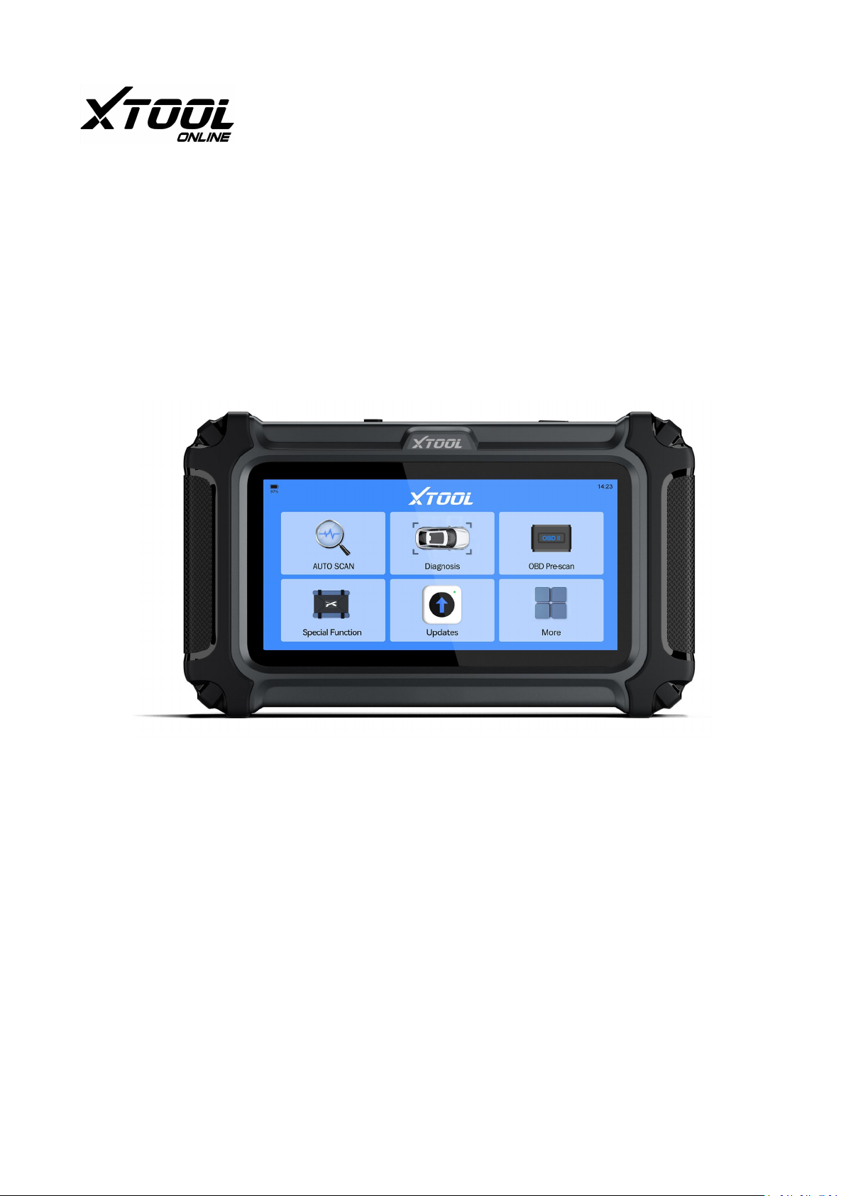
IP500-BMRB(BMW, MINI, Rolls-Royce)
Smart Diagnostic System
USER MANUAL
Xtoolonline
Update: 04/12/2024
Page 2

Legal Information
Trademarks
XTOOL is a registered trademark of Shenzhen XTOOL Technology Co., Ltd., in the
United States and other countries. This publication includes trademarks owned by
Shenzhen XTOOL Technology Co., Ltd., such as XTOOL. Any other trademarks
mentioned are the property of their respective owners.
Copyright Information
No part of this manual may be reproduced, stored in a retrieval system or
transmitted, in any form or by any means, electronic, mechanical, photocopying,
recording, or otherwise without the prior written permission of XTOOL.
© 2017 Shenzhen XTOOL Technology Co., Ltd. All rights reserved.
Disclaimer of Warranties and Limitation of Liabilities
The pictures and illustrations are for reference only. The information, specifications,
and illustrations in this manual were accurate when it was printed and may change
without notice. The authors have taken care in preparing this manual, but it does
not:
● Change the standard terms and conditions of the purchase, lease, or rental agreement through which the equipment covered by this manual was acquired.
● Increase liability to the customer or third parties in any way.
XTOOL will not be responsible for any direct, special, incidental, or indirect damages,
including economic losses such as lost profits.
XTOOL® also reserves the right to make changes at any time without prior notice.
IMPORTANT:
Before you start using or maintaining this unit, make sure to read this manual
thoroughly. Pay close attention to the safety warnings and precautions provided.
Page 3

Product Support Information
Technical Assistance
Website: https://www.xtoolonline.com
Mail: [email protected]
ADD: Room 601, Block A, Zaoan Bussiness Building, Shigu Road, Xili Residential
District, Nanshan District, Shenzhen
Corporate & Business: [email protected], [email protected]
Manuals / Technical Documentation
This manual is periodically revised to ensure the latest information is included.
Product Training Videos
Diagnostic Tool specific training videos are available on our website. Follow along
and learn the basics of Diagnostic Tool operation with our free training videos.
Videos are product specific and are available at: https://www.xtoolonline.com
/support/product-videos Click on the "Support"- "Product Videos"-"Diagnostic Tools"
tab, select the applicable Diagnostic Tool, then select the training video you want to
watch.
Safety Information
For your safety, the safety of others, and to prevent damage to devices and vehicles,
it is crucial to read and understand all safety instructions presented in this manual
before operating or coming into contact with the device.
General Safety Instructions:
● Read and Understand: Ensure that all operators and individuals in the vicinity of
the device have read and understood the safety instructions.
● Proper Use: Only use the device as described in this manual. Always adhere to the
safety messages and test procedures provided by the vehicle or equipment
manufacturer.
Page 4

● Knowledge and Skill: The automotive technician must be knowledgeable about the
system being tested. Familiarize yourself with proper service methods and test
procedures.
● Acceptable Testing Practices: Perform tests in a manner that ensures your safety,
the safety of others, and prevents damage to the device and the vehicle.
Specific Responsibilities:
● Refer to Manufacturer Guidelines: Always consult and follow the safety messages
and applicable test procedures from the vehicle or equipment manufacturer
before using the device.
● Use Appropriate Tools and Techniques: Due to the variety of test applications and
product variations, it's important to use the correct tools and techniques for each
specific task.
● Anticipate Safety Requirements: While this manual provides comprehensive
guidance, it cannot cover every potential situation. Technicians must be prepared
to handle unforeseen circumstances safely.
By adhering to these guidelines and responsibilities, you can ensure a safe and
effective working environment while using the device.
Safety Messages
Safety messages are included to prevent both personal injury and damage to
equipment. Each safety message begins with a signal word that indicates the level of
hazard involved.
Danger
This signal word "indicates an imminently hazardous situation which, if not avoided,
will result in death or serious injury to the operator or to bystanders."
Warning
This signal word "indicates a potentially hazardous situation which, if not avoided,
could result in death or serious injury to the operator or to bystanders."
Page 5

Safety Instructions
The safety messages provided here address situations that XTOOL is aware of. XTOOL
cannot anticipate, evaluate, or provide advice on all potential hazards. You must be
certain that any condition or service procedure encountered does not jeopardize
your personal safety.
Danger
When the engine is running, ensure the service area is well ventilated or connect a
building exhaust removal system to the engine exhaust. Engines emit carbon
monoxide, a colorless and poisonous gas that can impair reaction times and lead to
serious injury or even death.
Safety Warnings
Safe Environment: Always perform automotive testing in a safe environment.
Eye Protection: Wear safety eye protection that meets ANSI standards.
Avoid Hazards: Keep clothing, hair, hands, tools, and test equipment away from all
moving or hot engine parts.
Ventilation: Operate the vehicle in a well-ventilated work area to avoid inhaling
poisonous exhaust gases.
Transmission and Brakes: Put the transmission in PARK (for automatic) or NEUTRAL
(for manual) and ensure the parking brake is engaged.
Wheel Blocks: Place blocks in front of the drive wheels and never leave the vehicle
unattended while testing.
Ignition System Caution: Be extra cautious around the ignition coil, distributor cap,
ignition wires, and spark plugs, as these components generate hazardous voltages
when the engine is running.
Fire Extinguisher: Keep a fire extinguisher suitable for gasoline, chemical, and
electrical fires nearby.
Test Equipment Connections: Do not connect or disconnect any test equipment
while the ignition is on or the engine is running.
Clean Equipment: Keep the test equipment dry, clean, and free from oil, water, or
grease. Use a mild detergent on a clean cloth to clean the outside of the equipment
as necessary.
Page 6

No Driving While Testing: Do not drive the vehicle and operate the test equipment
simultaneously to avoid distractions that may cause an accident.
Service Manual Reference: Refer to the service manual for the vehicle being
serviced and adhere to all diagnostic procedures and precautions. Failure to do so
may result in personal injury or damage to the test equipment.
Battery Check: Ensure the vehicle battery is fully charged and the connection to the
vehicle DLC is clean and secure to avoid damaging the test equipment or generating
false data.
Avoid Electromagnetic Interference: Do not place the test device on the vehicle's
distributor, as strong electromagnetic interference can damage the device.
Page 7

Content
1. Introduction .......................................................................... 1
1.1 Data and Power Connections .........................................................................................................................1
1.2 Batter Pack and Stand.................................................................................................................................... 2
1.3 Main Ports of The Tablet................................................................................................................................ 2
1.4 Power Sources ................................................................................................................................................3
1.5 Internal Battery Pack ......................................................................................................................................3
1.6 AC Power Supply .............................................................................................................................................3
1.7 12-Volt Vehicle Power.................................................................................................................................... 3
1.8 Technical Specifications..................................................................................................................................3
1.9 What's In The Box ...........................................................................................................................................4
2.Getting Stared ........................................................................ 5
2.1 Turning On...................................................................................................................................................... 5
2.2 Turning Off......................................................................................................................................................5
2.3 Emergency Shutdown.....................................................................................................................................6
3.Get to Know the Diagnostic Tool .............................................6
3.1 Screen Layout & Screen Icons ........................................................................................................................ 6
3.2 Screen Layout ................................................................................................................................................. 7
3.3 Screen Icons ....................................................................................................................................................7
3.3.1 Auto Scan .............................................................................................................................................7
3.3.2 Diagnostic ............................................................................................................................................7
3.3.3 OBD-II .................................................................................................................................................. 7
3.3.4 Special Function.................................................................................................................................. 8
3.3.5 Updates ............................................................................................................................................... 8
3.3.6 More ....................................................................................................................................................8
4. How to Diagnose Vehicles ......................................................8
4.1 My Vehicles .....................................................................................................................................................9
4.1.1 Vehicle Coverage List...........................................................................................................................9
4.2 Software Program Version..............................................................................................................................9
4.3 Vehicle Voltage Display.................................................................................................................................10
4.4 Actuation Test...............................................................................................................................................10
4.5 Demo Program ............................................................................................................................................. 10
4.6 Wi-Fi Connection..........................................................................................................................................11
4.7 Product Activation ........................................................................................................................................12
4.7.1 Verification Code ...............................................................................................................................12
4.7.2 Delete Activation Information...........................................................................................................15
4.8 Vehicle Connection .......................................................................................................................................16
4.9 Diagnose Vehicles.........................................................................................................................................17
4.9.1 Auto Scan ...........................................................................................................................................18
4.9.2 Diagnostic ..........................................................................................................................................20
4.10 Diagnostics ..................................................................................................................................................21
Page 8

4.10.1 Read Codes ......................................................................................................................................21
4.10.2 Clear Codes......................................................................................................................................21
4.10.3 DTC Erased While Fault Remains.................................................................................................... 22
4.10.4 DTC Erased and Fault Fixed- History Code ......................................................................................22
4.10.5 DTC Erased and Fault Fixed- History Cleared ..................................................................................22
4.10.6 PID Data...........................................................................................................................................22
4.10.7 Freeze Frame...................................................................................................................................25
4.10.8 To Exit the Diagnostic Program.......................................................................................................26
4.10.9 Exiting Diagnostics ...........................................................................................................................26
4.11 Diagnostic Report.......................................................................................................................................26
4.12 Diagnostic Speed........................................................................................................................................27
4.13 Integrated Module ..................................................................................................................................... 27
5.OBD-II ...................................................................................28
5.1 OBD-II Protocols........................................................................................................................................... 29
5.2 Help ...............................................................................................................................................................29
5.3 10 Modes of OBD-II ......................................................................................................................................30
5.4 Connecting the Main Cable ..........................................................................................................................30
5.5 OBD-II/EOBD Menu......................................................................................................................................30
5.5.3 Clear Trouble Code(Mode $04).........................................................................................................34
5.5.4 Live Data(Mode $01).........................................................................................................................35
5.5.5 Read Freeze Frame(Mode $02).........................................................................................................37
5.5.6 I/M Readiness(Smog Check) ............................................................................................................. 37
5.5.7 O2S Monitoring Test(Mode $05) ...................................................................................................... 38
5.5.8 On-Board Monitor Test (Mode $06) ................................................................................................. 39
5.5.9 Component Test(Mode $08) .............................................................................................................40
5.5.10 Read ECU Information.....................................................................................................................40
6. Special Functions ................................................................. 40
6.1 Maintenance Light Reset..............................................................................................................................41
6.2 EPB ................................................................................................................................................................44
6.3 SAS ................................................................................................................................................................ 46
6.4 BMS Reset .....................................................................................................................................................48
6.5 Injector Coding .............................................................................................................................................50
6.6 DPF/GPF ........................................................................................................................................................52
6.7 Language Change ......................................................................................................................................... 54
6.8 ABS Bleeding.................................................................................................................................................54
6.9 Throttle Matching .........................................................................................................................................55
6.10 A/C Relearn .................................................................................................................................................56
6.11 Gearbox Matching ......................................................................................................................................56
6.12 Clutch Adaption ..........................................................................................................................................56
6.13 A/F Reset.................................................................................................................................................... 56
6.14 NOx Reset ...................................................................................................................................................56
6.15 Headlight Adjustment................................................................................................................................ 57
6.16 Seat Calibration ..........................................................................................................................................57
6.17 Disable Transport Mode .............................................................................................................................57
Page 9

6.18 Stop/Start Reset .........................................................................................................................................57
6.19 Windows Initialization................................................................................................................................57
6.20 Rain/Light Sensor....................................................................................................................................... 58
6.21 EGR Relearn ................................................................................................................................................58
6.22 Suspension System.....................................................................................................................................58
6.23 SRS .............................................................................................................................................................. 58
7. More ................................................................................... 58
7.1 My Account...................................................................................................................................................58
7.2 Diagnostic Report .........................................................................................................................................59
7.3 Settings .........................................................................................................................................................60
7.3.1 Language ........................................................................................................................................... 60
7.3.2 Unit ....................................................................................................................................................61
7.3.3 Wi-Fi Connection ...............................................................................................................................62
7.3.4 Display & Brightness..........................................................................................................................62
7.3.5 Storage ...............................................................................................................................................63
7.3.6 Date & Time.......................................................................................................................................63
7.3.7 About .................................................................................................................................................64
8. Software Updates................................................................ 65
9.Other Functions ....................................................................66
9.1 Print the Report............................................................................................................................................66
9.2 Data Logging .................................................................................................................................................67
9.3 FAQ Database............................................................................................................................................... 67
9.4 Corporate Purchase ......................................................................................................................................67
9.5 Inventors and Testers Program.....................................................................................................................67
10. Compliance Information .................................................... 68
10.1 FCC Compliance / FCC ID: 2AW3IF510.......................................................................................................68
10.2 UKCA...........................................................................................................................................................69
10.3 RF Warning Statement ............................................................................................................................... 69
10.4 ROHS Compliance .......................................................................................................................................69
10.5 CE Compliance ............................................................................................................................................69
10.6 ISED .............................................................................................................................................................70
11.Warranty............................................................................ 70
Limited Two-Year Warranty................................................................................................................................70
12. Appendix ........................................................................... 71
12.1 Navigation Path Quick Check..................................................................................................................... 71
12.2 Terms & Terminology Quick Check.............................................................................................................71
12.3 FAQs............................................................................................................................................................72
13. Contact Us ......................................................................... 75
Warranty & Support ........................................................................................................................................... 75
Page 10

1
1. Introduction
The XTOOL IP500-BMR is a powerful diagnostic tool tailored for BMW, MINI, and
Rolls-Royce vehicles, offering full-system diagnostics for components such as the
engine, transmission, ABS, airbag, and HVAC to facilitate quick issue identification
and resolution. It features 23 diagnostic-specific functions and vehicle-specific
functions under each vehicle's software, and the combination of these two types of
functions ensures greater compatibility with your vehicle.
Featuring a robust 1.2GHz dual-core CPU, 128MB of RAM, and 32GB of expandable
storage on a Linux OS, it has a 5.45-inch display with a 1440x720 resolution for
excellent outdoor visibility and a long-lasting 3150mAh battery.
Its lightweight, compact design and rugged casing ensure portability and reliability,
while over 4,000 active tests enable efficient troubleshooting by commanding
specific vehicle components, including window and fuel pump operations.
The tool also supports advanced ECU coding, allowing customization and
reprogramming of settings for optimized performance. With a full suite of OBD2
diagnostics, it can perform essential tests such as retrieving trouble codes and
monitoring live data, making it suitable for novice engineers, professional mechanics,
and DIY enthusiasts alike.
Additionally, it offers lifetime free upgrades, ensuring continuous access to the latest
features and long-term value.
This chapter introduces the basic features of the Diagnostic Tool, including the
control buttons, data ports, battery pack, and power sources. Technical
Specifications are provided at the end of this chapter.
1.1 Data and Power Connections
Page 11
2
1.2 Batter Pack and Stand
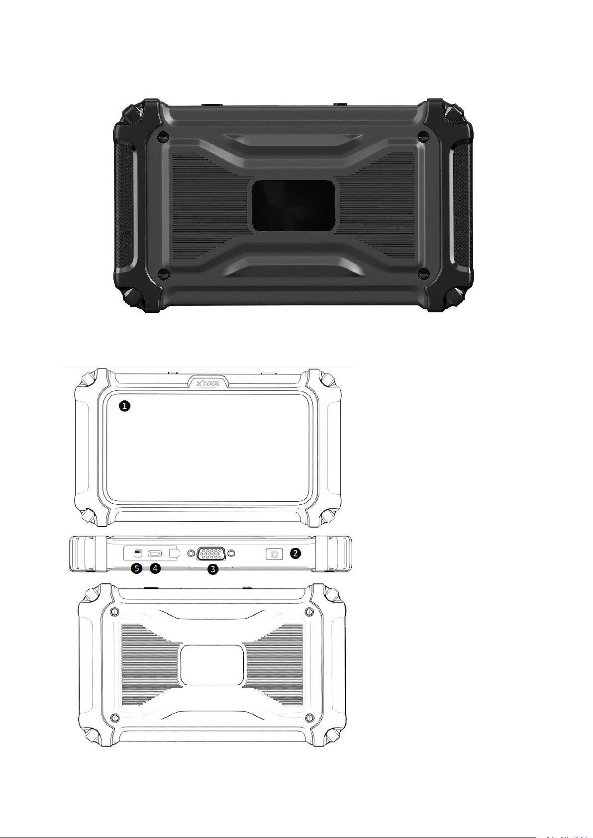
❶ 5-inch Touch Screen
❷ Power Button
❸ VGA15PIN-Port
❹ Type-C Port
❺ Memory card slot
1.3 Main Ports of The Tablet
Page 12

3
1.4 Power Sources
Item
Description/Specification
The XTOOL D5S Diagnostic Tool can receive power from the following three methods:
● Internal Battery Pack
● AC Power Supply
● 12-Volt vehicle power
1.5 Internal Battery Pack
The IP500-BMR Diagnostic Tool can be powered from the internal rechargeable
battery pack. A fully charged battery provides sufficient power for about 3.5 hours of
continuous operation.
Battery charging occurs when the Diagnostic Tool is connected to the AC Power
Supply and to a live AC power source.
1.6 AC Power Supply
You can power the Diagnostic Tool by connecting it to a standard AC outlet using the
AC power supply. The connector at the end of the output cable from the AC power
supply should be plugged into the DC power supply input jack located on the top of
the Diagnostic Tool. It's important to use only the AC power supply that was
provided specifically for this purpose to ensure proper and safe operation of the
tool.
1.7 12-Volt Vehicle Power
Locate the vehicle's OBDII port, which is typically found beneath the driver's seat,
near the steering wheel. Insert the 16-pin connector of the OBDII cable into the
vehicle's OBDII port, and connect the 15-pin end of the OBDII cable to the device,
tightening the nut to ensure a secure connection.
1.8 Technical Specifications
Page 13

4
Display
5.45 Inch(1440*720 Resolution
)
Operating System
Linux
Protocols Supported
CAN FD
Processor
Quad-core 1.2 Hz
Memory
128M+32G (supports memory expansion up to
128G)
Connectivity
Type-C
Operating Method
Flat Panel Touchscreen
Upgrade Method
Device Connects to Wi-Fi for Online Upgrade
Battery
3150mAh 3.6V
Wi-Fi
2.4G/5Ghz
Tested Battery Life
3.5 Hours
Dimensions
19.5*2.8*11.5(CM)
Free Renewal Update
Lifetime
Charging Method
Type-C Charging
Sensor
Gravity/ Light Sensor
Audio
Microphone
Speaker
Built-In Speaker
Weight(Including Battery)
0.4KG
Gross Weight
0.84KG
Operating Temp Range(Ambient)
-4°F ~ 140°F (-20°C ~ 60°C)
Storage Temp(Ambient)
-40~158°F (-40~70°C)
Operating Humidity
<90%
1.9 What's In The Box
Name
QTY
IP500-BMR
1
VAG to OBD-II-16 Main Cable
1
Quick Guide
1
Packing List
1
Carton
1
Type-C Charging Cable
1
Page 14

5
2.Getting Stared
Ensure that the Diagnostic Tool is adequately powered by either checking its battery
status or connecting it to an external power supply (refer to Power Sources on page
2 for details).
NOTE:
The images and illustrations depicted in this manual may differ from the actual ones
due to color discrepancies and image reproduction quality.
Turn on/off or Force Shutdown
The following sections explain how to turn the XTOOL IP500-BMR Diagnostic Tool on
and off, as well as how to perform an emergency shutdown.
2.1 Turning On
To turn on the XTOOL IP500-BMR Diagnostic Tool, press and hold the power button
located on the top right of the device for approximately five seconds. The tool will
automatically power on if the internal battery pack has sufficient charge or if it is
connected to an AC power supply. If the internal battery pack is completely drained,
you need to charge it for more than 6 hours and then turn it on again.
2.2 Turning Off
To turn off the XTOOL IP500-BMR Diagnostic Tool, press and hold the power button
for more than three seconds. The tool will then automatically power off.
IMPORTANT:
Before turning off the XTOOL IP500-BMR Diagnostic Tool, make sure to terminate all
vehicle communications. If you try to power off the tool while it is still
communicating with the vehicle, a warning message will appear. Forcing a shutdown
during communication could potentially cause issues with the ECM (Engine Control
Module) on certain vehicles. It's crucial never to disconnect the DBD-15 main cable
while the Diagnostic Tool is actively communicating with the vehicle ECM.
Page 15

6
2.3 Emergency Shutdown
During normal operation turn the Diagnostic Tool off using the Turning Off procedure
above. The emergency shutdown procedure should only be used if the Diagnostic
Tool does not respond to navigation or control buttons or operates erratically. To
force an emergency shutdown, press and hold the Power button for at least five
seconds.
IMPORTANT:
Using the emergency shutdown procedure while communicating with the vehicle
ECM may cause issues with the ECM on some vehicles.
3.Get to Know the Diagnostic Tool
This chapter details the layout and icons of the diagnostic screen of the tablet used
with the Diagnostic Tool.
3.1 Screen Layout & Screen Icons
When you turn on the Diagnostic Tool, you will see the diagnostic screen appear. The
following section provides details about the layout of the diagnostic screen.
Page 16
7
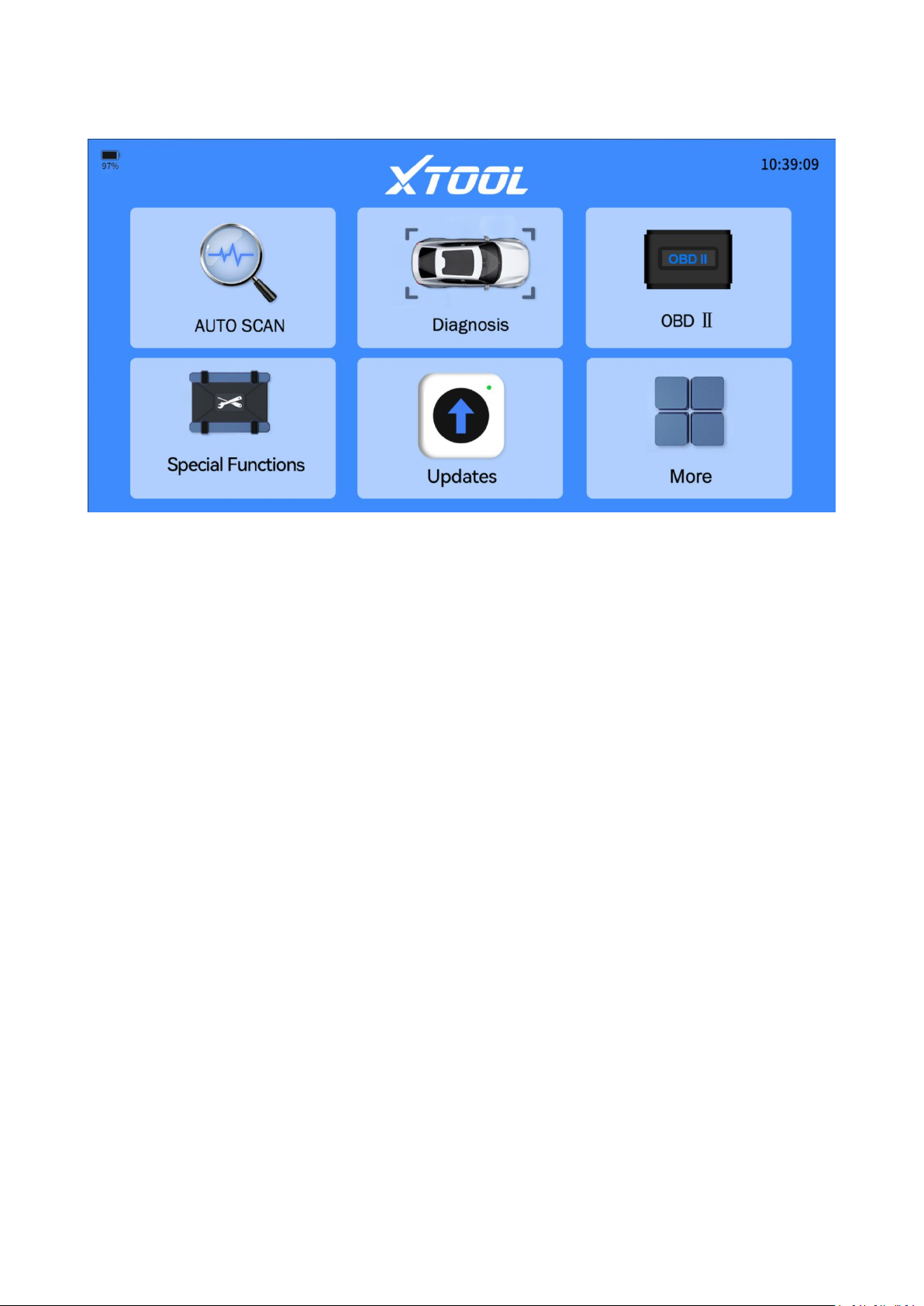
3.2 Screen Layout
3.3 Screen Icons
3.3.1 Auto Scan
The Diagnostic Tool automatically detects and decodes the VIN (Vehicle
Identification Number), then proceeds to scan comprehensively through all available
vehicle electronic control modules for diagnostics. This process ensures thorough
assessment and identification of potential issues across the vehicle's systems.
3.3.2 Diagnostic
Clicking the "Diagnostic" icon will bring up the diagnostic menu. From there, you can
navigate using Auto VIN to automatically detect the vehicle's details or manually
input vehicle information such as make, model, year, and configuration for
diagnostics. You can perform vehicle diagnostics after selecting the correct model.
3.3.3 OBD-II
OBDII (On-Board Diagnostics) functions include reading vehicle fault codes, clearing
codes, monitoring real-time data (such as engine RPM, vehicle speed, etc.), and
Page 17

8
detecting emission system issues. These features help quickly diagnose and maintain
the vehicle's health.
3.3.4 Special Function
This section covers the most commonly performed maintenance services used by
both car repair Do-It-Yourselves and professionals for day-to-day auto maintenance
tasks.
3.3.5 Updates
This section allows you to download diagnostic software programs individually or in
batches.
3.3.6 More
This section allows you to perform several tasks:
Set up the user account and workshop profile, if applicable.
Access firmware information.
You can view the diagnostic report here.
Change the language
Modify the measurement units during the diagnostic process.
Etc...
4. How to Diagnose Vehicles
This chapter covers the fundamental operation of the Diagnostic Tool function.
The Diagnostic Tool function enables communication with a vehicle's electronic
control systems. This capability allows you to retrieve diagnostic trouble codes
(DTCs), view PID data, and perform advanced functions such as resets, relearns,
matchings, adaptations, initializations, and more.
Page 18
9
4.1 My Vehicles
"My vehicles" function allows you to add the diagnostic programs you use often to
save time navigating the vehicles.
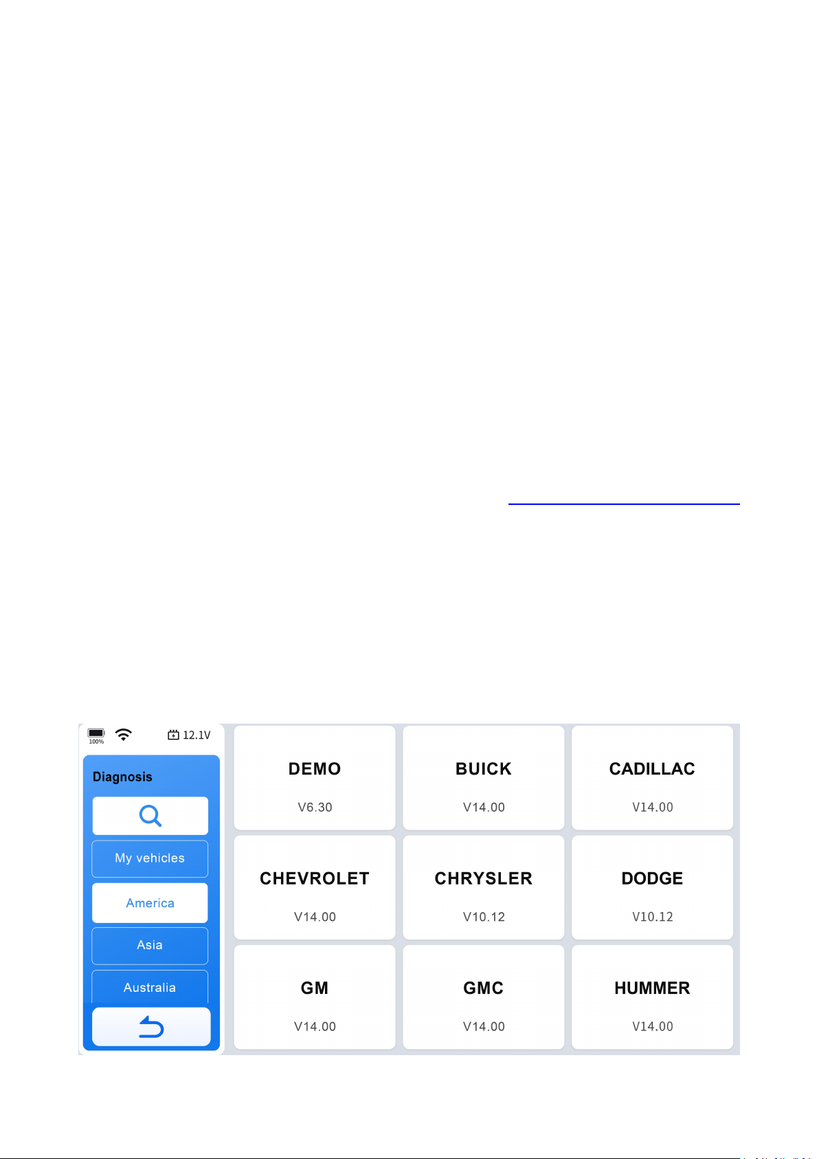
Click "Diagnostic" icon on the diagnostic screen, you will see "My vehicles" listed in
the top left taskbar. To add diagnostic program that you use often into this section,
click the add icon> select the brand of your vehicle > click "completed" to finish
adding brands operations.
To remove a diagnostic program for "My vehicles" list, click the pen icon select the
diagnostic program you want to remove> click "Remove" to finish removing it from
the list.
4.1.1 Vehicle Coverage List
To check compatibility, please consult tech support via [email protected] at
any time or refer to our website: https://www.xtoolonline.com
/support/vehicle-coverage (for reference only, subject to confirmation from tech
support: [email protected]).
4.2 Software Program Version
This Diagnostic Tool displays the current software program version at the bottom of
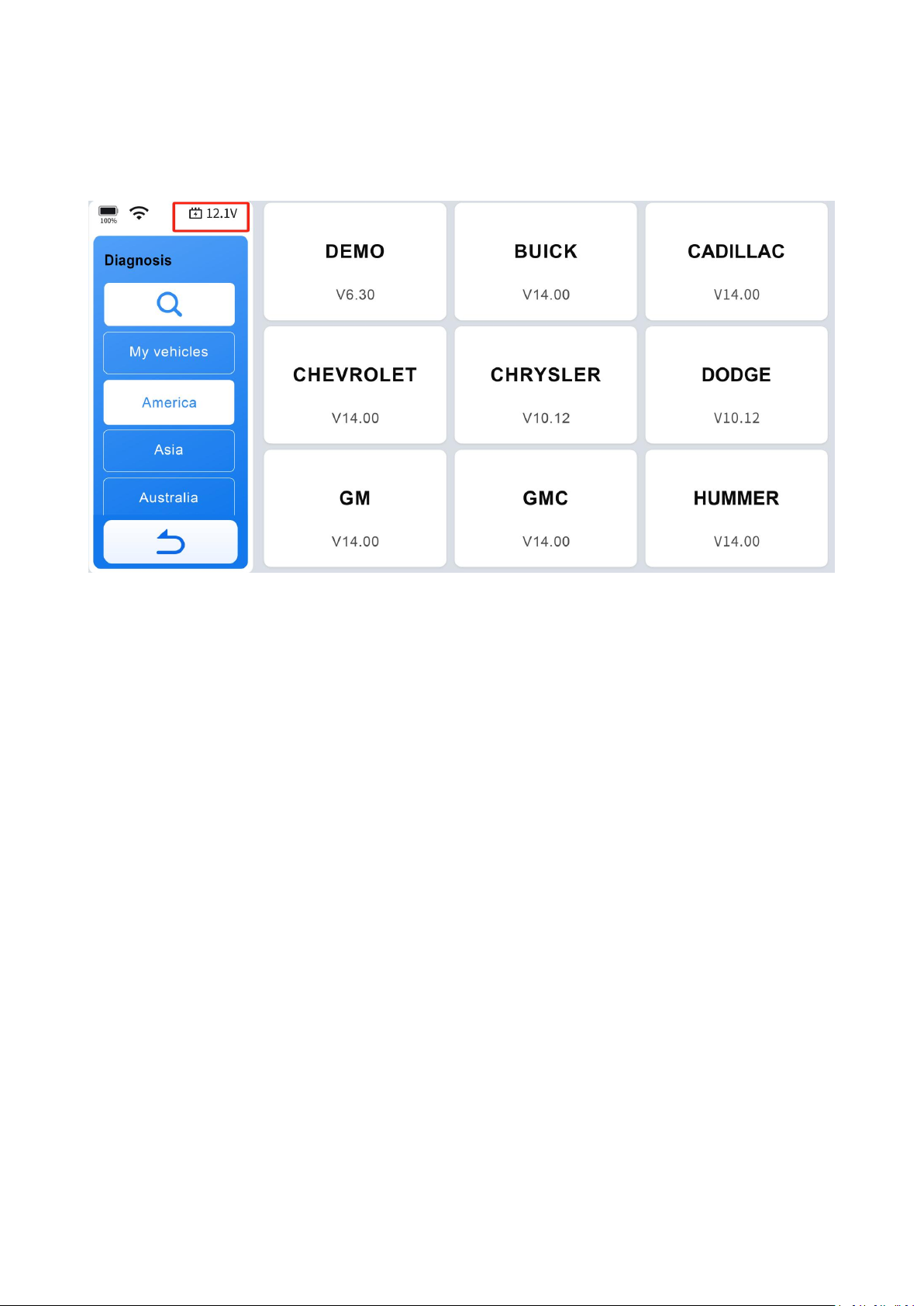
each vehicle manufacturer's screen. For instance, the current installed BUICK
software program is V14.00, as depicted in the picture below:
Page 19
10
4.3 Vehicle Voltage Display
The area circled in red in the image shows the real-time voltage of the vehicle's
battery, allowing you to monitor the battery voltage while using the device.
4.4 Actuation Test
Actuation test, also known as bidirectional control, is a generic term used to describe
sending and receiving information between one device and another. The scan tool
can request information or command a module to perform specific tests or functions.
Some manufacturers refer to the bidirectional controls as function tests, actuation
tests, inspection tests, system tests. Reinitialization and reprogramming would also
be included in the list of bidirectional controls. Most enhanced scan tools also can
actuate relays, injectors, and coils, perform system tests, etc. Users could check the
individual part to see which part is working properly by actuation test.
4.5 Demo Program
The "DEMO" program simulates the vehicle navigation process, displays available
function options, and demonstrates the appearance of the menu. It serves as a
training tool to familiarize yourself with the operations and capabilities of the
Diagnostic Tool.
Page 20

11
IMPORTANT:
The DEMO program may not display the most current vehicle diagnostic procedures
or the actual screen interface. It is not intended for checking vehicle coverage or
compatibility.
4.6 Wi-Fi Connection
This Diagnostic Tool can connect to 2.4 GHz or 5.0 GHz Wi-Fi or hotspot. Click More>
Settings> Wi-Fi connection> Switch on Wi-Fi connection> Select the Wi-Fi you want
to connect and enter the password to connect.
If the Wi-Fi connection is unstable, or if you are in an area without access to home
Wi-Fi, you can connect to your mobile phone hotspot instead.
How to turn on the mobile hotspot:
● For iOS users
Go to Settings> Turn on cellular network> Personal Hotspot> Switch on ''Allow
Others to Join'' and ''Maximize Compatibility'' to set up your phone's hotspot. Then,
connect the Diagnostic Tool to the hotspot by following the steps mentioned earlier.
● For Android users
Go to Settings> Wireless & networks> Tethering & portable hotspot> Portable WLAN
hotspot> Switch on hotspot> Configure WLAN hotspot> Encryption Type> WPA2 PSK.
In ''Show Advanced Options,'' ensure that ''Max connections allowed'' has available
slots for the Diagnostic Tool.
NOTE:
A Wi-Fi connection is not necessary for diagnostics with most vehicle brands.
However, for certain brands, like Peugeot, that require access to an online server for
diagnostics, it is essential to connect to Wi-Fi.
Page 21
12
4.7 Product Activation
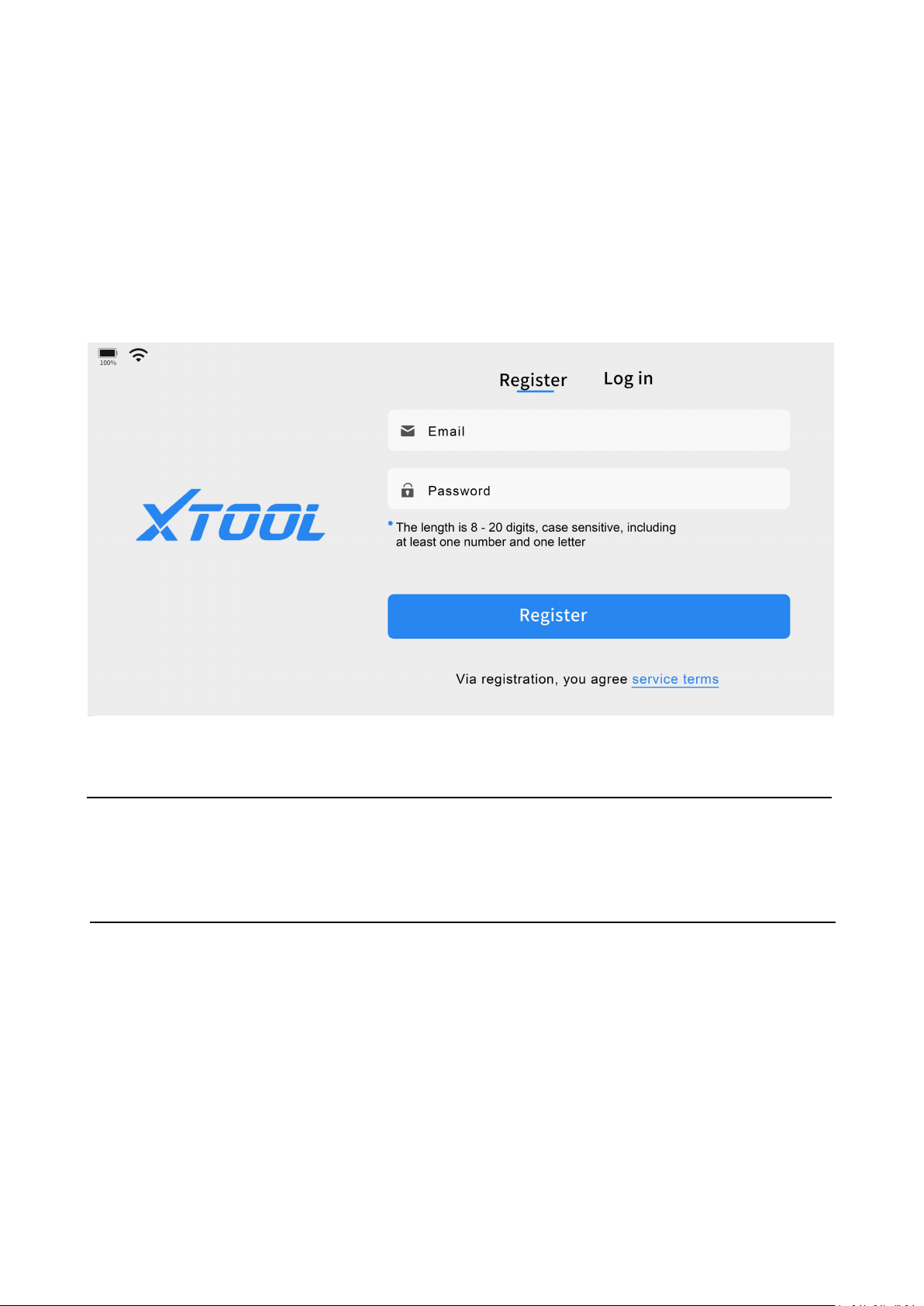
Step 1: Select an available Wi-Fi network.
Step 2: For first-time users, after pressing and holding the power button to turn on
the system, the system will automatically enter a guided process and prompt the
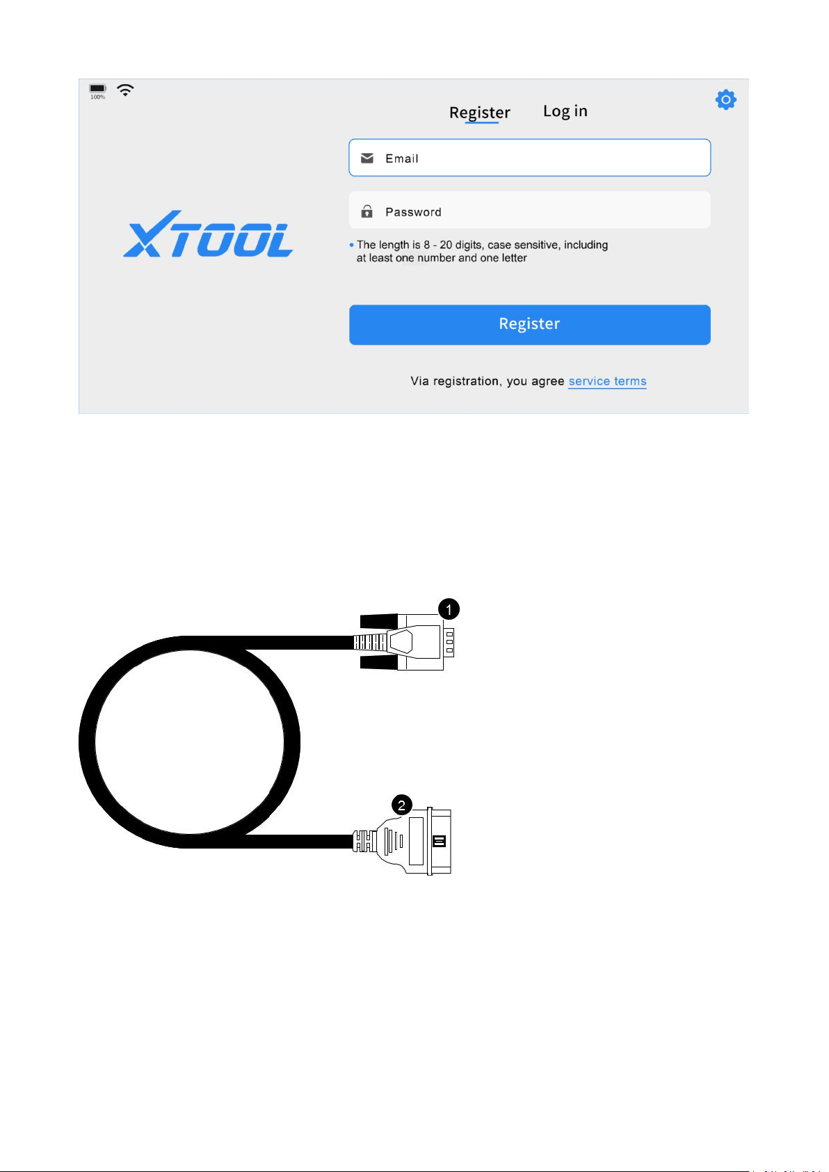
user to enter a valid email address and set a login password. Click "Register" to open
the registration page. If you have already registered, click the login button and enter
your email and password to log in.
Step 3: Click "Start to use" to enter the diagnostic system and begin using the device.
NOTE:
If you are unable to register the Diagnostic Tool or you can't see the activation
screen, contact our support team via [email protected].
4.7.1 Verification Code
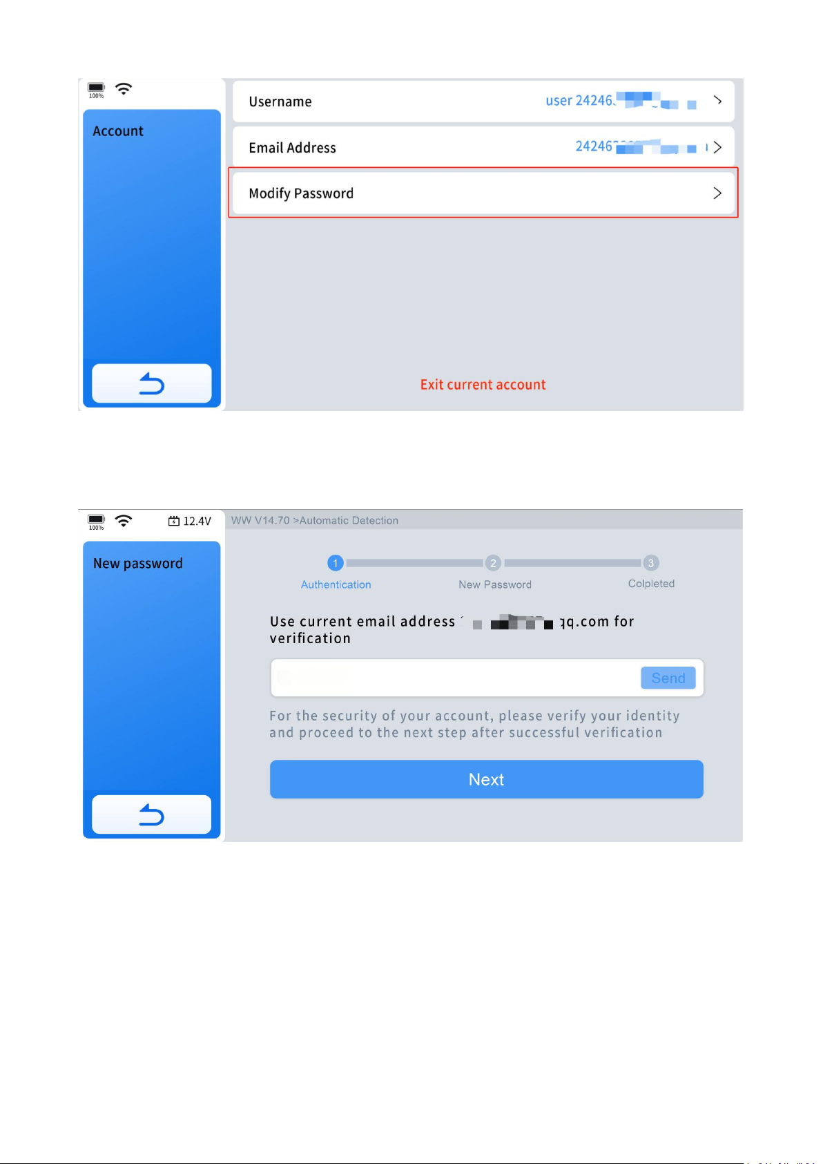
Step 1: If you forget your password, enter More menu, click "Profile-Account-Modify
password".
Page 22
13
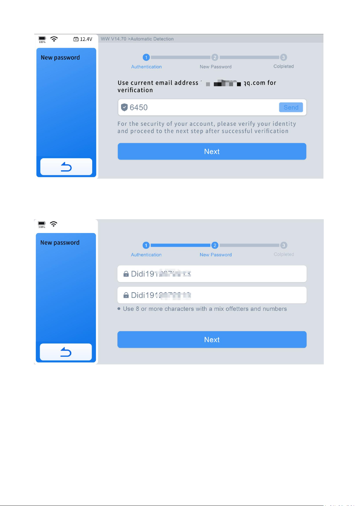
Step 2: Make sure your network is stable. Then click "Send" button, and we will send
a four-digit verification code to your registered email.
Step 3: Enter the four-digit code in the "Verification code" field, and then click
"Next." If you don't see the verification code in your inbox, please check your spam
folder.
Page 23
14
Step 4: Enter the new password you want to set. You need to enter it twice; the
second entry is to confirm that the first entry is correct.
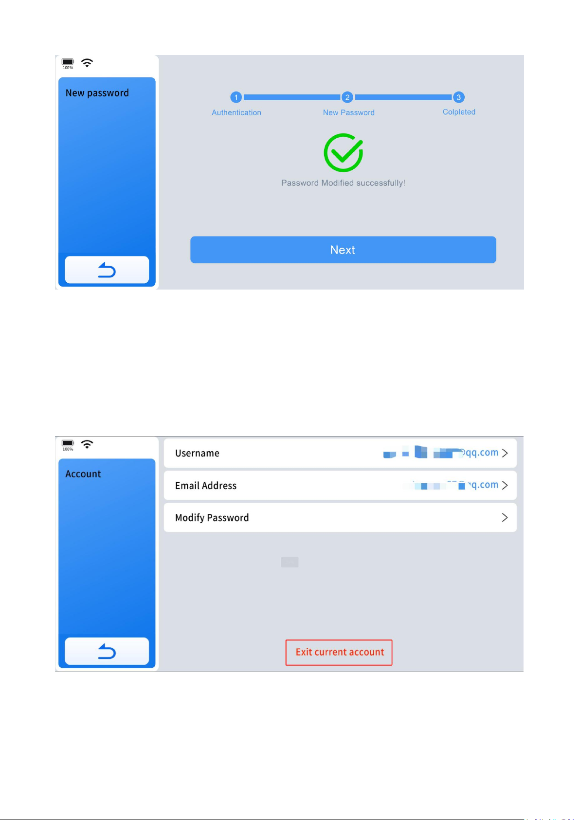
Step 5: After clicking "Next," when the page displays a message "Password Modified
Successfully!", it means the operation was successful.
Page 24
15
If the success message does not appear, please try again in a stable network
environment.
4.7.2 Delete Activation Information
If you want to clear the currently logged-in information, here are the reference steps.
Enter "More" menu, click "Profile-Account-Exit current account", and click OK.
Return to the initial registration page. If you want to create a new account, click
"Create Account." If you want to log in to an existing account, click "Log In."
Page 25
16
4.8 Vehicle Connection
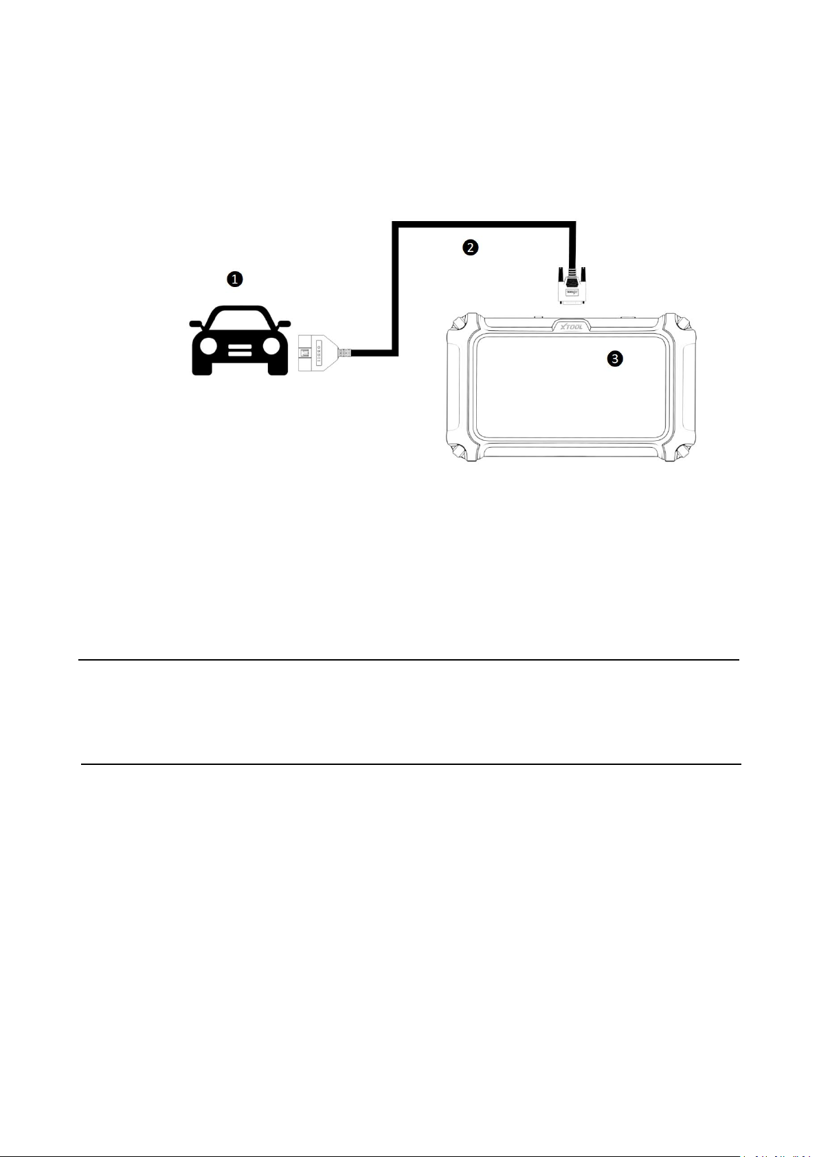
❶ VGA Port-connect to tablet
❷ OBD2-16 Connectorconnect to vehicle’s OBD port
⚫ OB15 to OBD2-16 Main Cable
⚫ Vehicle Connection
The scan tool must be connected to the vehicle's OBD-II port to allow the tablet to
establish communication with the vehicle.
Please perform the following steps:
Step 1: Turn on the tablet.
Page 26
17
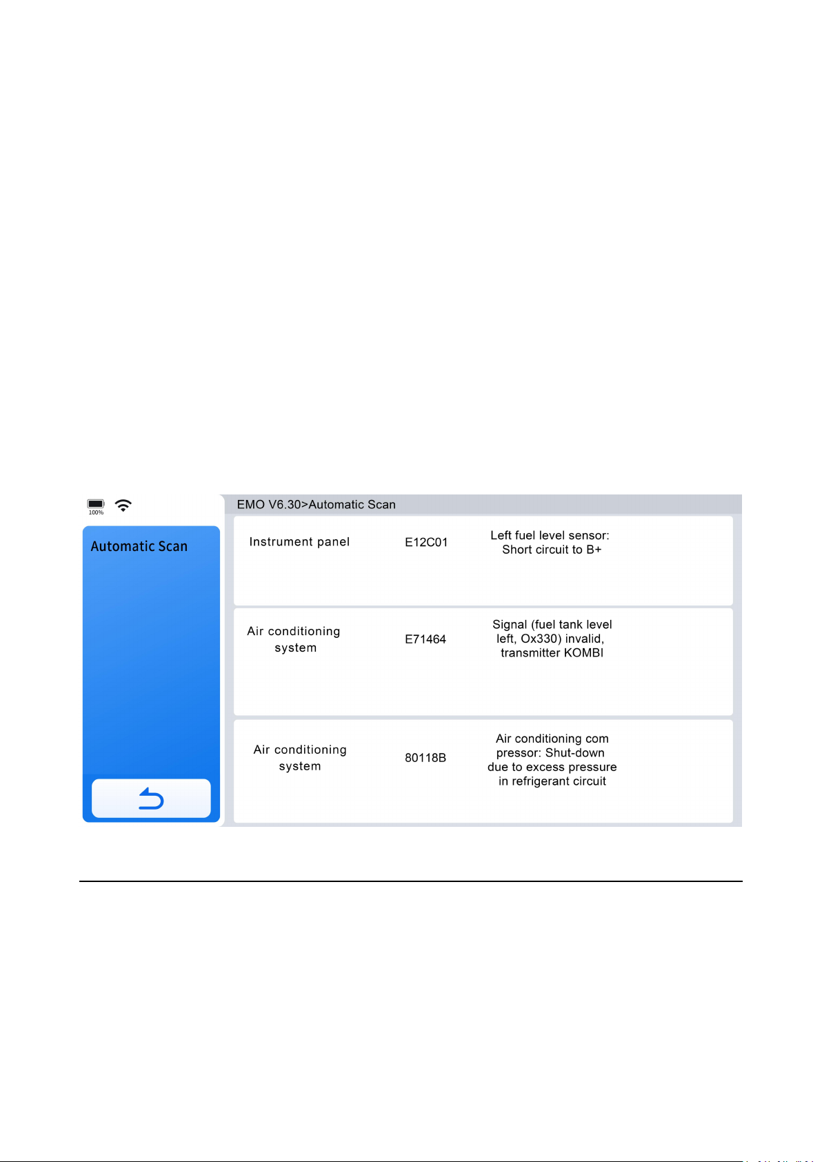
Step 2: Connect the vehicle and tablet using the main test cable.
Step 3: Turn on the vehicle's ignition switch to start the diagnostic process.
The connection method is shown in the figure below:
❶ Vehicle
❷ OB15 to OBD2-16 Main Cable
❸ Tablet
NOTE:
If the OBD port of your vehicle is located on the chassis or in a hard-to-reach area,
you can contact us to purchase an OBD extension cable for easier operation.
4.9 Diagnose Vehicles
To ensure proper communication and diagnostics, the vehicle must be correctly
identified. The vehicle identification process is menu-driven, and you should follow
the screen prompts to enter the required information. Exact procedures may vary
depending on the region and the vehicle manufacturer.
Steps to Identify a Vehicle:
Page 27
18
Step 1: Follow the screen prompts to enter the necessary vehicle information.
Step 2: Options for Vehicle Identification include:
⚫ VIN (Vehicle Identification Number)
⚫ Region
⚫ Manufacturer and Model
⚫ Other specific criteria as required by the Diagnostic Tool
4.9.1 Auto Scan
4.9.1.1 Auto Identification
Click the "Auto Scan"> "Auto Identification" icon on the diagnostic screen, and the
Diagnostic Tool will automatically scan and decode the vehicle's VIN for
identification.
IMPORTANT:
There is a common misconception that the Diagnostic Tool cannot perform
diagnostics if it fails to detect or decode the VIN. If the Auto Scan option fails, it's
recommended to try other vehicle identification methods. Use Manual Selection as
a reliable alternative to manually enter the vehicle's region and manufacturer. This
Page 28
19
ensures you can proceed with diagnostics even if automatic VIN detection is
unsuccessful.
NOTE:
Auto Identification functionality may not be compatible with all vehicles. If Auto
Identification fails, it is advisable to try alternative options.
4.9.1.2 Manual Input
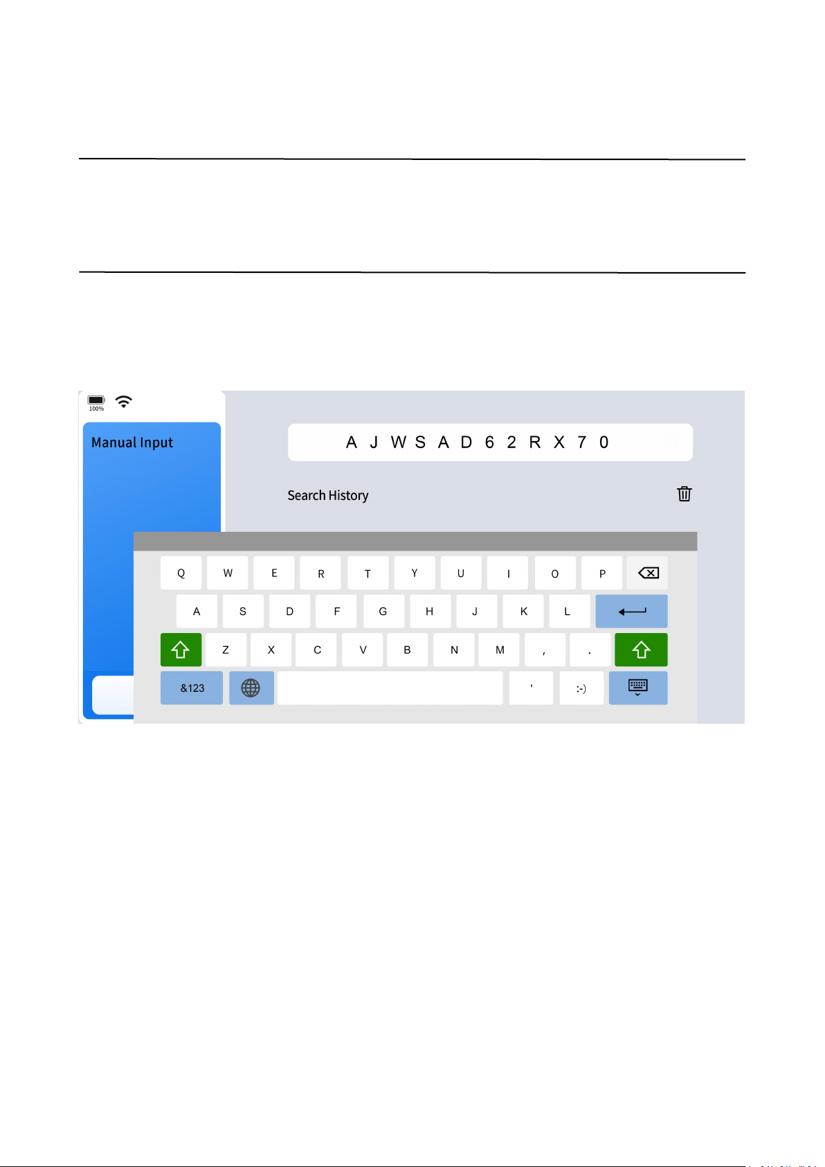
When the automatic scan cannot identify the vehicle, it is recommended to
manually input the VIN to recognize the vehicle.
There are four reasons why it cannot be scanned automatically.
The vehicle is too old to come with AUTO SCAN function on itself.
The VIN is not written in the ECU of the vehicle, you will need to write the VIN in
the ECU first.
The VIN is too rare or too new and it is not recorded in the VIN database.
Vehicle of the same model might have different configurations and the
information provided in VIN is not enough to select the correct vehicle, so you
will need to manually select the configurations.
Page 29

20
4.9.2 Diagnostic
Click "Diagnostic" icon on the screen, the Diagnostic Tool will bring up vehicle
selection menu.
NOTE:
In cases where vehicle VIN numbers cannot be decoded, if both Auto Identification
and Manual Input failed, it is recommended to try using Manual Selection instead.
4.9.2.1 Automatic Detection
Click "Diagnostic"> Select region where the vehicle brand is originated, for example
"Americas"> Select the vehicle brand, for example "CADILLAC"> Select "Automatic
Detection" to automatically detect and identify the vehicle the Diagnostic Tool is
connected to.
4.9.2.2 Manual Selection
When the "Auto Scan" and "Manual Input" fails to identify the vehicle, you can
always select "Manual Selection" to identify the vehicle and proceed to diagnostics.
Manual Selection is the most reliable vehicle identification option.
To identify a vehicle through "Manual Selection", click "Diagnostic"> Select the
vehicle brand, for example "CADILLAC"> Select region where the vehicle brand is
originated, for example "Americas"> Select "Manual Selection"> Select the model
year> Model Name and you may go through a few other selections before you see
"Automatic Scan" and "System Selection" on the screen.
4.9.2.2.1 Automatic Scan
It is to scan available vehicle modules for diagnostics.
4.9.2.2.2 System Selection
Once you have identified the potential issues with the vehicle, you can select an
individual vehicle module for diagnostics. This enables more targeted and efficient
troubleshooting.
Page 30
21
4.10 Diagnostics
Once the vehicle is correctly identified, the Diagnostic Tool will be able to scan and
access the vehicle's electronic control systems to retrieve diagnostic trouble codes
(DTCs), PID data (Parameter IDs), freeze frame data, and ECU information.
4.10.1 Read Codes
When viewing the diagnostic trouble code (DTC) records retrieved from the vehicle's
electronic control module, selecting them may open a sub-menu with viewing
options.
During the diagnosis process, if the Diagnostic Tool displays ''System is OK'' or ''No
Trouble Code,'' it indicates that either there are no related fault codes stored in the
ECU or that faults are not monitored by that specific ECU. Many faults may be
related to mechanical system issues or circuit operation problems. It's also possible
that a sensor signal may be inaccurate but within acceptable limits, which can be
further examined using Live Data (PID).
4.10.2 Clear Codes
This function erases DTC records, including both current and historical data, as well
as other stored information from the vehicle's electronic control module (ECM).
Page 31

22
When the erase command is sent through the diagnostic program, the vehicle's
electronic control module (ECM) will verify whether the issue has been resolved over
multiple drive cycles. Some faults are immediately detected by the ECU when the
ignition key is in the ''run'' position, even without the engine running. However,
other faults may require very specific test conditions to be met, such as engine
coolant temperature within a specific range, vehicle speed maintained for a certain
duration, throttle position within a defined range, etc.
4.10.3 DTC Erased While Fault Remains
If fault codes are erased while the underlying issue remains unresolved, the fault
codes will reappear after a few drive cycles.
4.10.4 DTC Erased and Fault Fixed- History Code
If the fault has been fixed but a trouble code remains stored, the ECU may
sometimes detect the resolution and either clear the fault code or reclassify it as a
historical code.
4.10.5 DTC Erased and Fault Fixed- History Cleared
If the fault has been fixed and you clear the fault codes, the fault history will also be
erased. If another technician is going to investigate the issue, it’s not recommended
to clear the fault codes, as this may erase valuable information that could assist in
diagnosing the problem.
NOTE:
Clearing codes typically erases the freeze frame data associated with those codes.
4.10.6 PID Data
Displays PID data for various sensors from the vehicle electronic control module. This
Diagnostic Tool allows viewing real-time PID data of various sensors in a list, view
Page 32
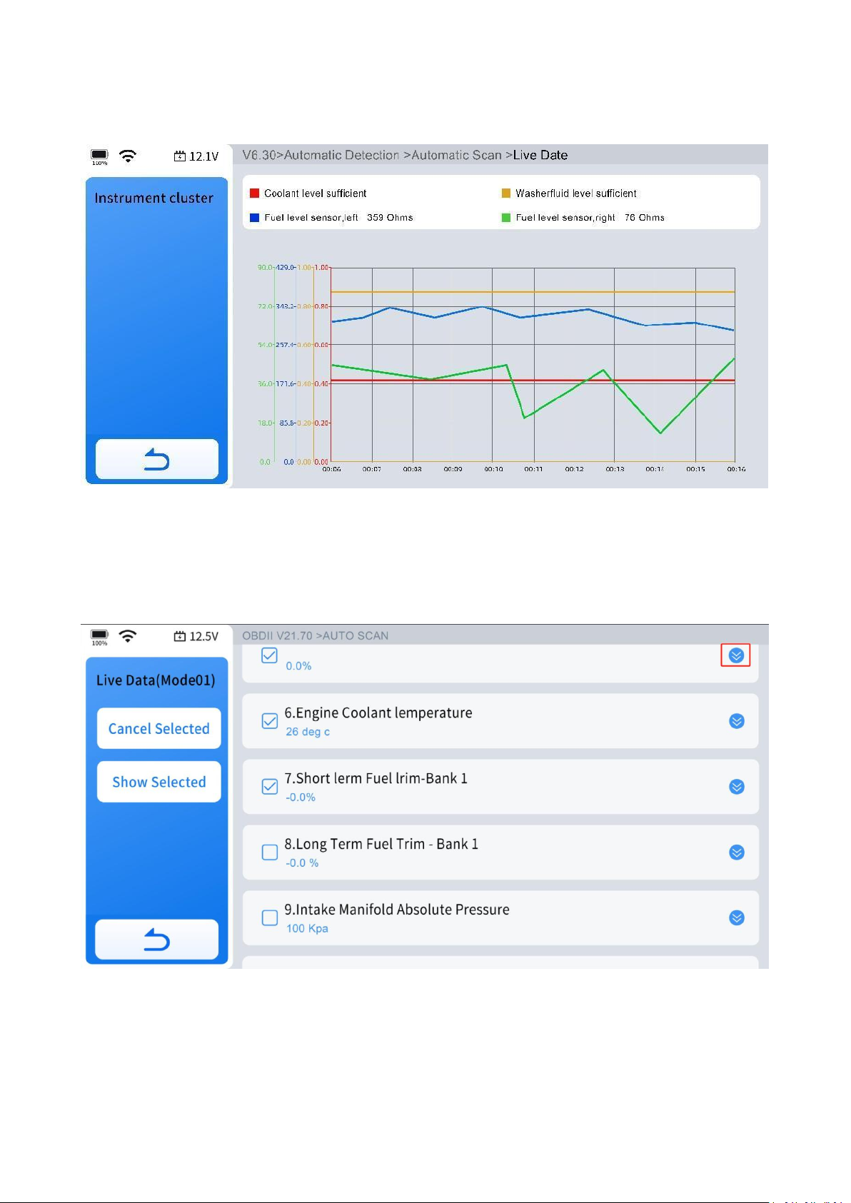
23
individual PID data in graphing, analog dashboard, view custom PID data up to 4
sensors in a list, individual graphing and merged graphing.
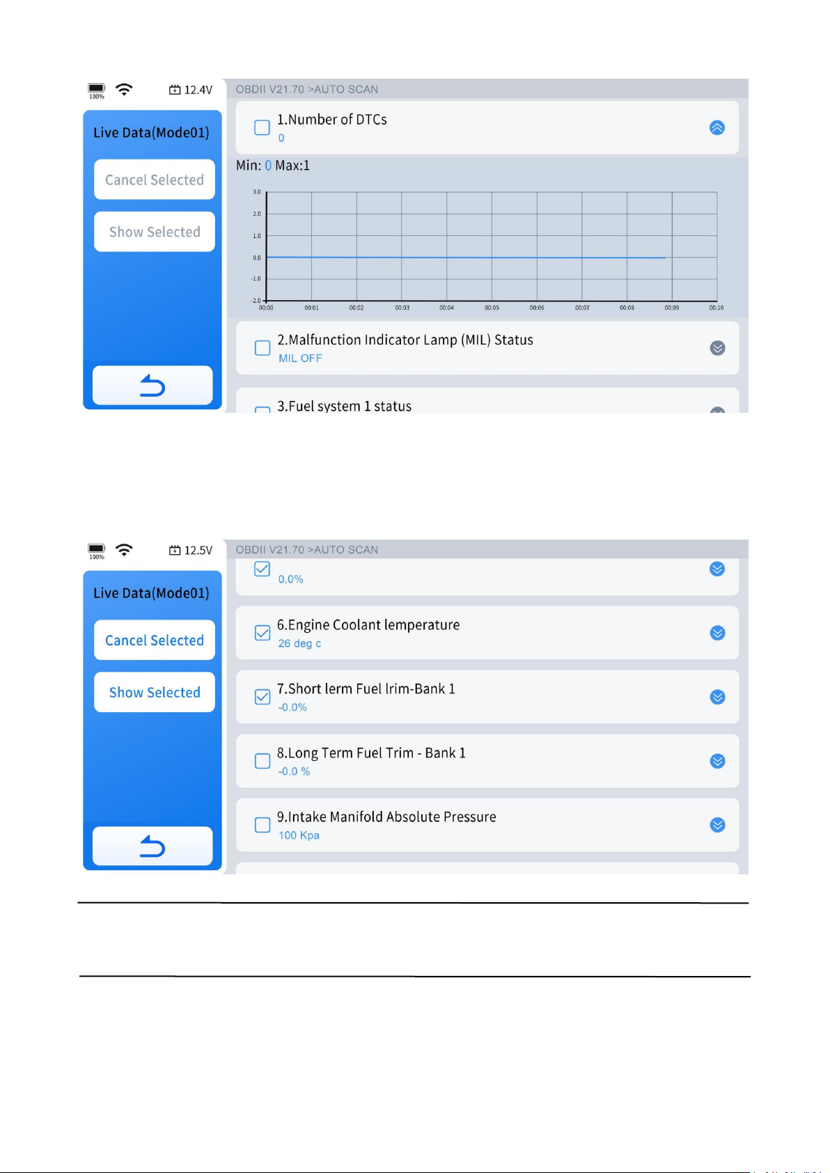
4.10.6.1 View Waveform Chart
Click the circled area in the diagram to view the waveform chart for each data
stream.
Page 33
24
4.10.6.2 Select Live Data
After selecting the data streams you want to view, click "Custom" to display only the
selected data streams, without interference from other data streams.
NOTE:
You can select up to four data streams at a time.
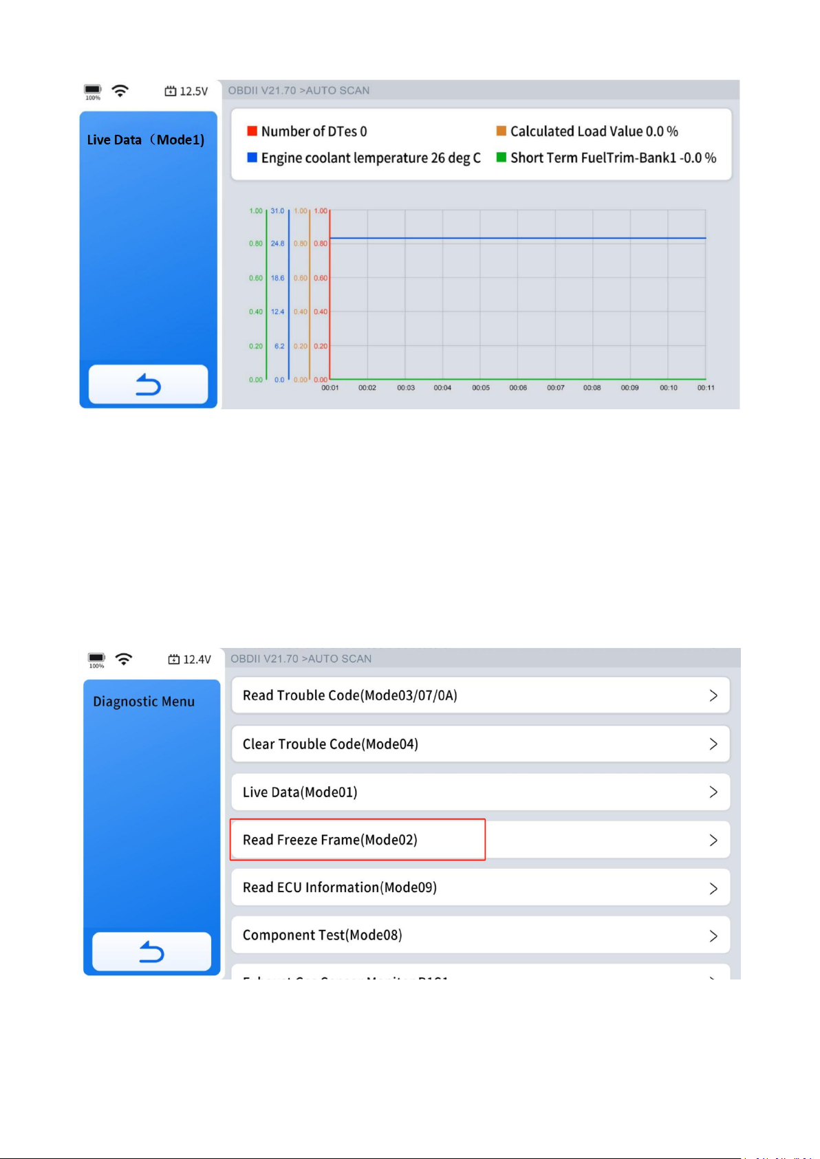
4.10.6.3 4-IN-1 Live Data
Select the data streams you want to view, click "Custom-Combine," and you will get
a combined 4-in-1 graphical data stream.
Page 34
25
4.10.7 Freeze Frame
When a fault code is triggered, the vehicle's ECU saves related data from that
moment to generate a freeze frame. It is typically used to analyze the root cause of
the fault, along with fault codes and PID data. The freeze frame data displayed varies
across vehicles, and some vehicles may not support freeze frame functionality.
Page 35
26
4.10.8 To Exit the Diagnostic Program
Exiting all diagnostic programs and returning to the main diagnostic screen will end
the diagnosis.
4.10.9 Exiting Diagnostics
Diagnostics remain active as long as there is an active communication link with the
vehicle. To exit tests and turn off the Diagnostic Tool, you must first interrupt this
communication link. A warning message will appear if you manage to shut down the
Diagnostic Tool while it is communicating with the vehicle.
NOTE:
Damage to the vehicle's electronic control module (ECU) may occur if
communication is disrupted. Always ensure the main cable is securely connected
during testing. Be sure to exit all tests before disconnecting the main cable or
turning off the Diagnostic Tool.
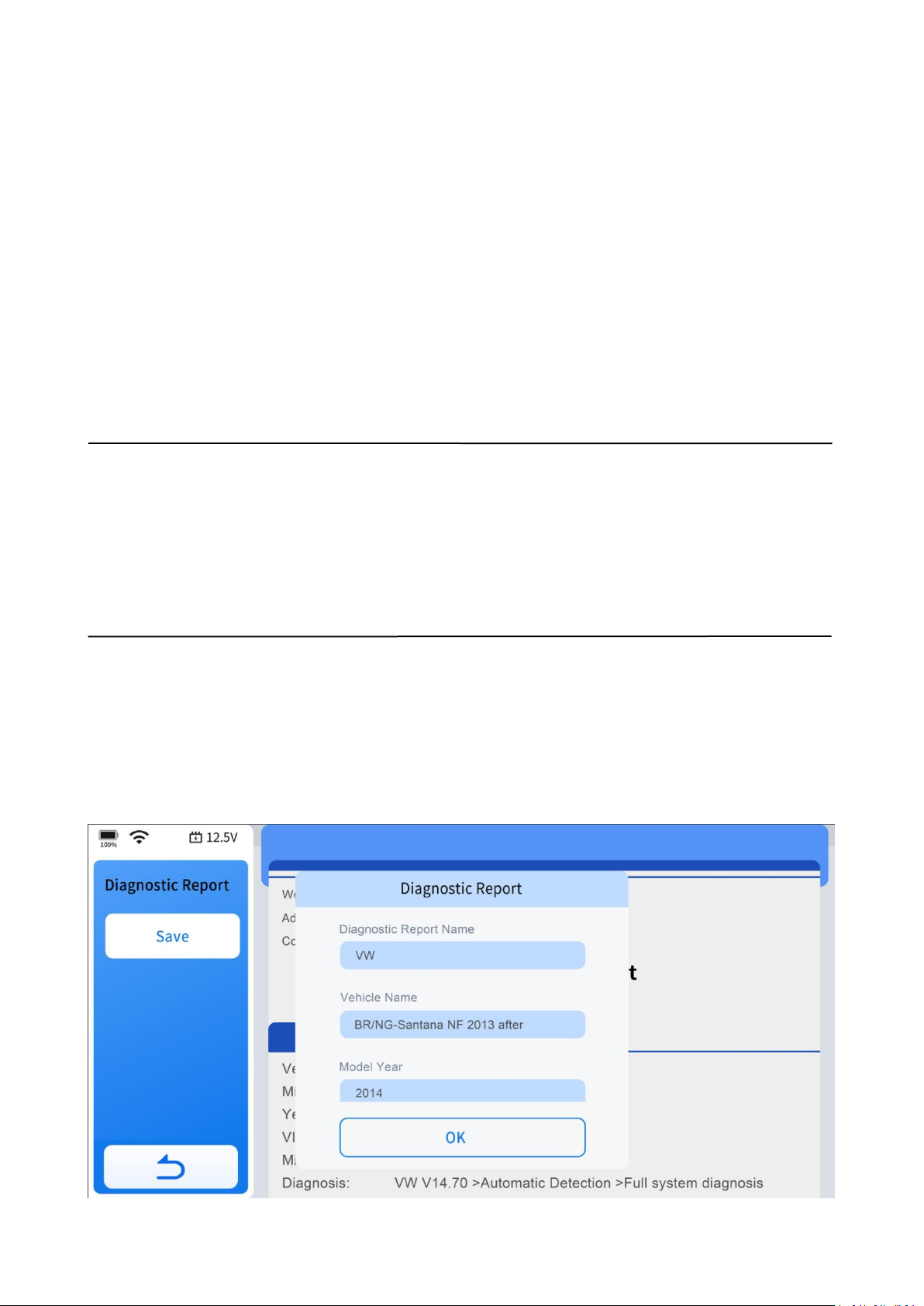
4.11 Diagnostic Report
After completing the diagnostics and returning to the main screen, enter the VIN,
mileage, and model year. Click "OK" on the report generation form to create a
diagnostic report for later review or sharing.
Page 36

27
Go to "Diagnostic Report" in the More menu to view all generated diagnostic reports.
Click on the report you want to review based on its date and time, or share it via
email by clicking "Share by E-mail".
4.12 Diagnostic Speed
The Diagnostic Tool provides fast scanning and diagnostics for all vehicle modules.
However, the time it takes to scan and diagnose all modules varies across vehicles.
Factors that could influence diagnostic speed include the vehicle's communication
protocol and the number of control modules it has.
Generally speaking, the Diagnostic Tool scans all modules faster on vehicles using the
latest communication protocols than on older ones. For example, scanning a vehicle
that uses the CAN protocol takes less time than one using the older ISO9141
protocol. Additionally, it takes longer to scan a modern vehicle with many modules
than a less sophisticated vehicle with only a few modules.
4.13 Integrated Module
In some cases, particularly with older vehicle models, manufacturers may integrate
two or more electronic control systems into a single vehicle module. This integration
can lead to confusion or complexity during the diagnostic and repair process.
Listed below are two most common examples:
Powertrain Control Module(PCM)- Integrates Engine and Transmission systems.
Brake Control Module(BCM)- Integrates ABS and EPB systems.
The information above indicates that if you cannot find "Transmission" or a similar
option in the diagnostic menu, you should look for "Transmission Oil Temperature"
under the PID (live data) menu in the Powertrain Control Module (PCM). Similarly, if
you are searching for the ABS Bleeding feature, go to the Special Function under the
Brake Control Module (BCM). This approach helps you locate specific diagnostic
features within the Diagnostic Tool.
Page 37
28
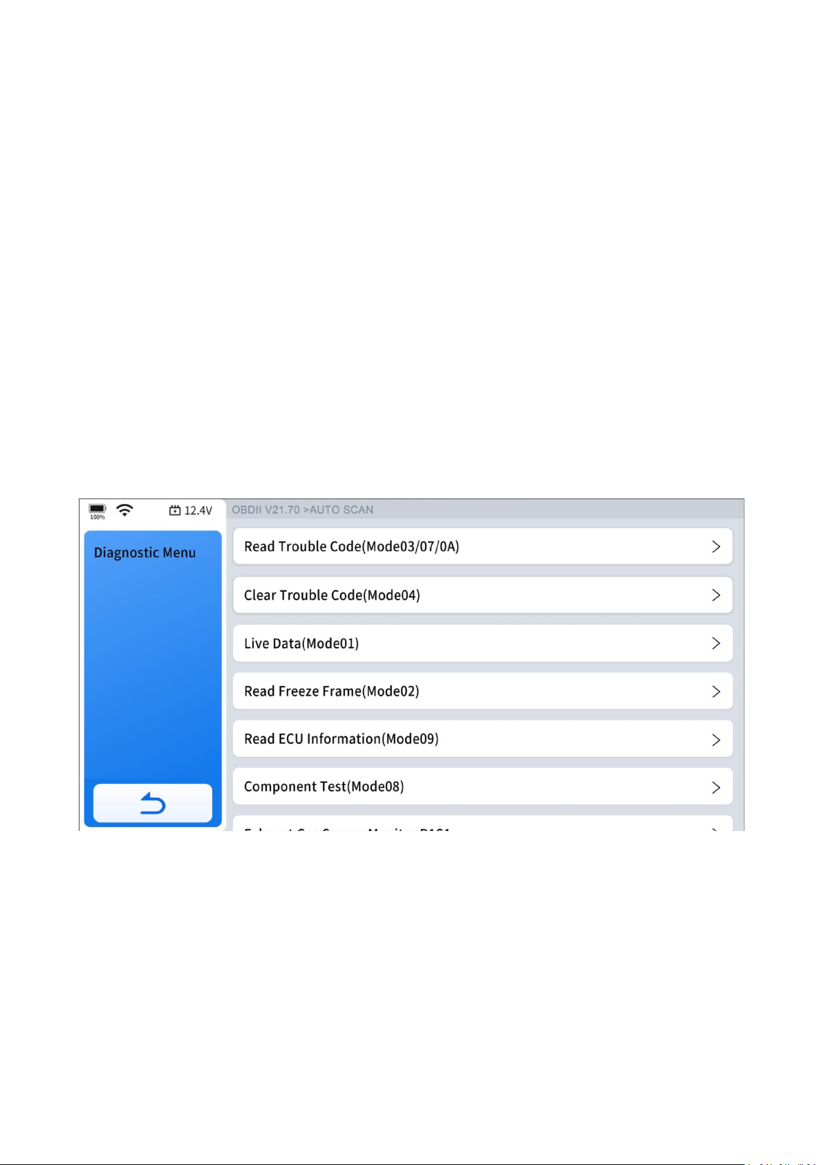
5.OBD-II
This chapter describes the concept, protocols, test functions, and basic operation of
the OBD-II/EOBD function.
This option provides a quick way to check DTCs, identify the cause of an illuminated
malfunction indicator lamp (MIL), check monitor status prior to emissions
certification testing, verify repairs, and perform other emissions-related services.
The OBD-II function allows you to access "generic" OBD-II data.
Generic OBD-II data is data limited to emission related diagnostics such as:
• Checking for emissions-related diagnostic trouble codes (DTCs)
• Checking the cause of an illuminated malfunction indicator lamp (MIL)
• Checking monitor status prior to emissions certification testing
To access other available electronic control module (ECU) data for vehicle-specific
systems, parameters, or enhanced diagnostics, use ''Auto Scan'' or ''Diagnostic'' to
access all systems or individual system diagnostics. The OBD-II function is used to
access ''generic'' OBD-II/EOBD data for OBD-II/EOBD compliant vehicles that are not
included in the all systems or individual systems diagnostics.
Page 38
29
IMPORTANT:
Generic OBD-II data are not included in the engine system diagnostic data.
5.1 OBD-II Protocols
Global OBD uses 5 communication protocols:
• SAE J1850PWM
• SAEJ1850VPW
• ISO 9141-2
• ISO 14230-4
• ISO 15765-4
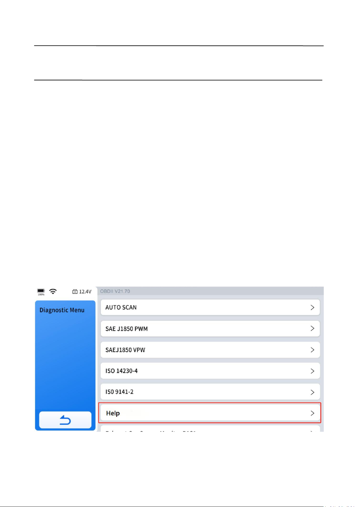
5.2 Help
Describes DLC location position, DTC library, Abbreviations and OBD background
information like OBD-II modes and etc.
Page 39

30
5.3 10 Modes of OBD-II
Mode $01 – Live Data
Mode $02 – Read Freeze Frame
Mode $03 – Read Trouble Code
Mode $04 – Clear Trouble Code
Mode $05 – O2S Monitoring Test
Mode $06 – On-Board Monitor Test
Mode $07 – Read Trouble Code
Mode $08 – Component Test
Mode $09 – Read ECU Information
Mode $0A – Read Trouble Code
5.4 Connecting the Main Cable
The main cable must be connected to both the Diagnostic Tool and the vehicle's
OBD-II port for OBD-II testing. For details, refer to ''Vehicle Connection'' on page 16.
5.5 OBD-II/EOBD Menu
5.5.1 Read Trouble Code
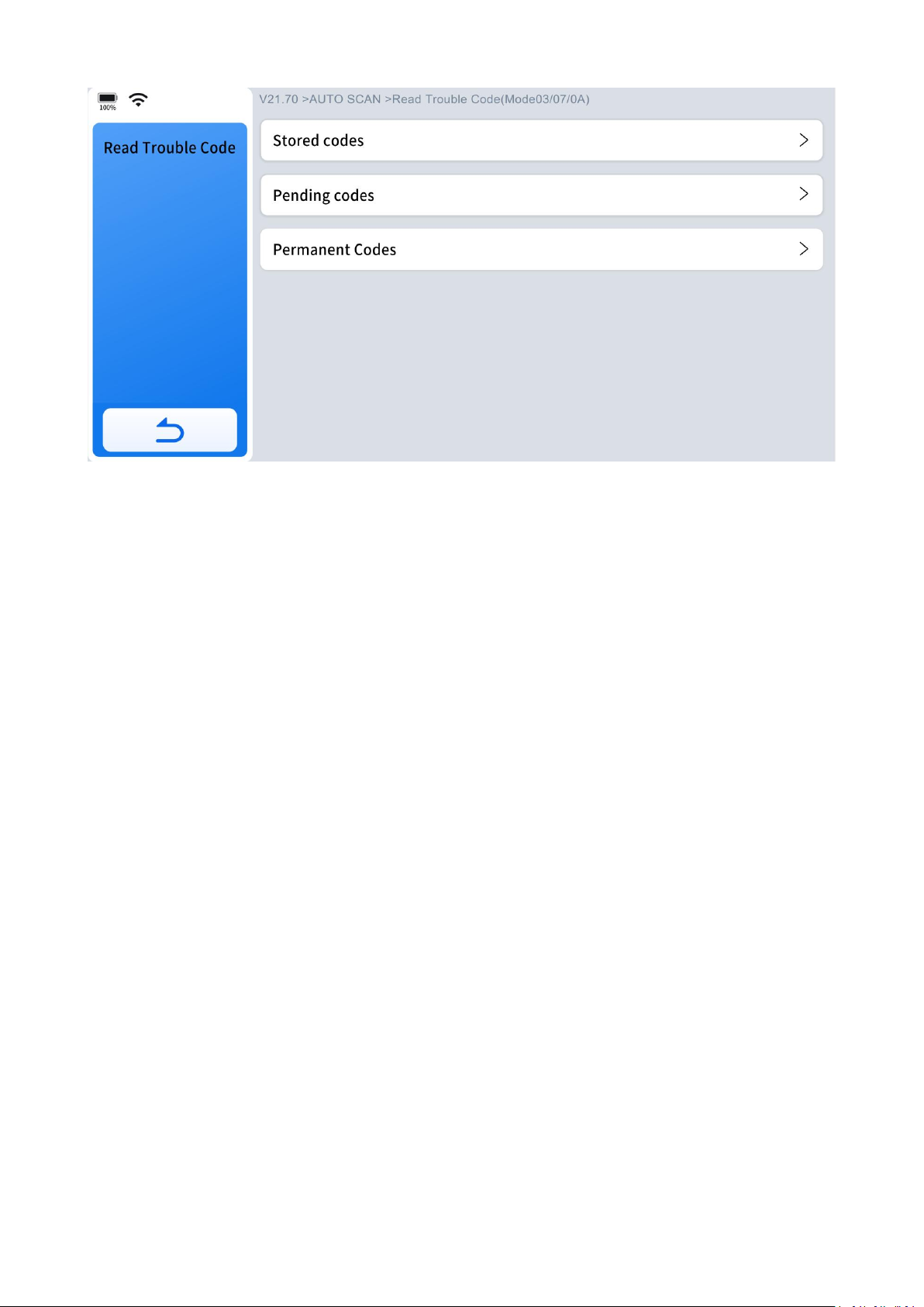
The "Read Trouble Code" option displays a list of current emission-related DTCs,
including Stored Codes (Generic and Manufacturer-Specific Codes), Pending Codes,
and Permanent Codes.
Page 40
31
OBD-II codes are prioritized based on their emission severity, with higher priority
codes taking precedence. This prioritization affects whether the Malfunction
Indicator Lamp (MIL) illuminates and how the code erase procedure is managed.
Different vehicle manufacturers implement these priorities in various ways, leading
to differences in how codes are ranked and addressed across different makes and
models.
5.5.1.1 Stored Codes
Stored codes refer to current emission-related DTCs from the vehicle's ECM. OBD-II
codes are prioritized based on their emission severity, with higher priority codes
overriding lower priority ones. The priority of the code determines whether the MIL
is illuminated and how the code erase procedure is handled. Vehicle manufacturers
implement this ranking differently, leading to variations between makes.
5.5.1.2 Pending Codes
The purpose of this function is to enable the Diagnostic Tool to obtain "pending" or
maturing diagnostic trouble codes. These are codes whose setting conditions were
met during the last drive cycle, but need to be met on two or more consecutive drive
cycles before the DTC actually sets.
Page 41

32
Use this function following a vehicle repair and code clearing procedure to verify test
results after a single drive cycle.
● If a test failed during the drive cycle, the DTC associated with that test is reported.
If the pending fault does not occur again within 40 to 80 warm-up cycles, the fault
is automatically cleared from memory.
● Test results reported by this function do not necessarily indicate a faulty
component or system. If test results indicate another failure after additional
driving, then a DTC is set to indicate a faulty component or system, and the MIL is
illuminated.
5.5.1.3 Permanent Codes
This option displays a record of any "Permanent" codes. A permanent status DTC is
one that was severe enough to illuminate the MIL at some point, but the MIL may
not be on at the present time.
Whether the MIL was switched off by clearing codes or because the setting
conditions did not repeat after a specified number of drive cycles, a record of the
DTC is retained by the ECM. Permanent status codes automatically clear after repairs
have been made and the related system monitor runs successfully.
5.5.1.4 Generic & Manufacturer-Specific Codes
Code Definitions:
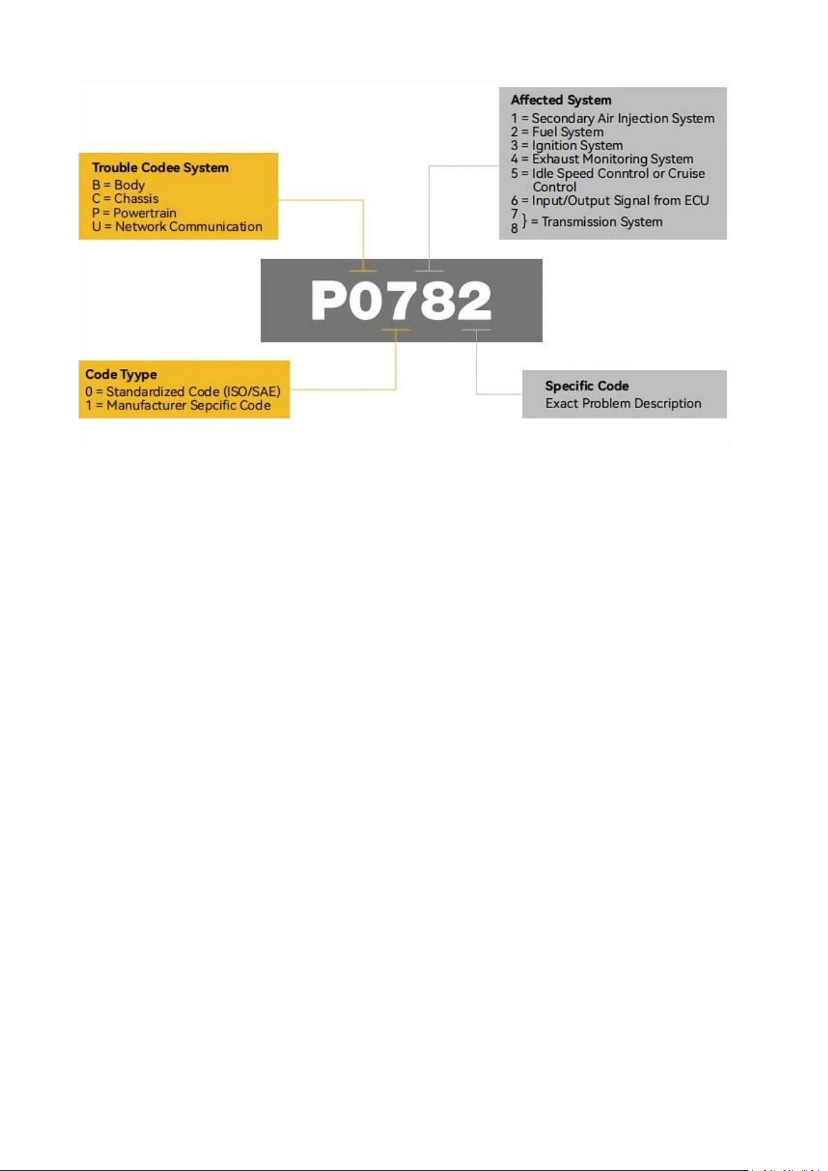
Diagnostic Trouble Code (DTC) -- Trouble codes are how OBD-II identifies and
communicates to technicians where and what on-board problems exist. The first
number in the DTC indicates whether the code is an SAE generic code (applies to all
OBD-II systems) or is specific to the vehicle manufacturer. The remaining three
numbers provide information regarding the specific vehicle system and circuit. An
analysis of a typical OBD-II code is shown below.
Generic Codes -- DTC with the second character as "0" is a Generic Code.
Manufacturer-Specific Code -- DTC with second character as "1" is a
Manufacturer-Specific Code.
Page 42
33
5.5.1.5 Definition of Fault Code
5.5.1.5.1 First DTC Character
The first DTC character is always a letter. There are four types of codes:
● P codes, "P" indicates a problem with the powertrain. It includes the engine,
transmission, drivetrain, and fuel system.
● C codes, "C" indicates a problem with the chassis. It refers to mechanical systems
outside the passenger compartment, such as steering, suspension, and braking.
● B codes, "B" indicates a problem with the body. It covers parts that are found in
the passenger compartment area.
● U codes, "U" indicates a problem with the vehicle's onboard computers and
integration functions that the OBD manages.
5.5.1.5.2 Second DTC Character
The second DTC character is a numeric digit, either a "0" or a "1":
0, A "0" indicates a standard SAE international code. It's also known as a generic
code, meaning that it applies to all vehicles following the OBD-II international
standard.
Page 43

34
1, A "1" represents a code that is specific to the car's make or model. It's known as
an enhanced code, meaning it doesn't fall under an SAE standard. If you see a "1,"
reach out to the vehicle manufacturer directly for more information.
5.5.1.5.3 Third DTC Character
If the second DTC character is a "0," then the third character helps you determine
which subsystems are malfunctioning. There are nine numbers:
0, Fuel and air metering and auxiliary emission controls
1, Fuel and air metering injection system
2, Fuel and air metering (injection system)
3, Ignition systems or misfires
4, Auxiliary emission controls
5, Vehicle speed control, idle control systems, and auxiliary inputs
6, Computer output circuit
7-8, Transmission
5.5.1.5.4 Fourth and Fifth DTC Character
The fourth and fifth DTC codes are two-digit numbers from 0 to 99, known as the
"Specific Fault Index." It identifies the exact malfunction that a vehicle has.
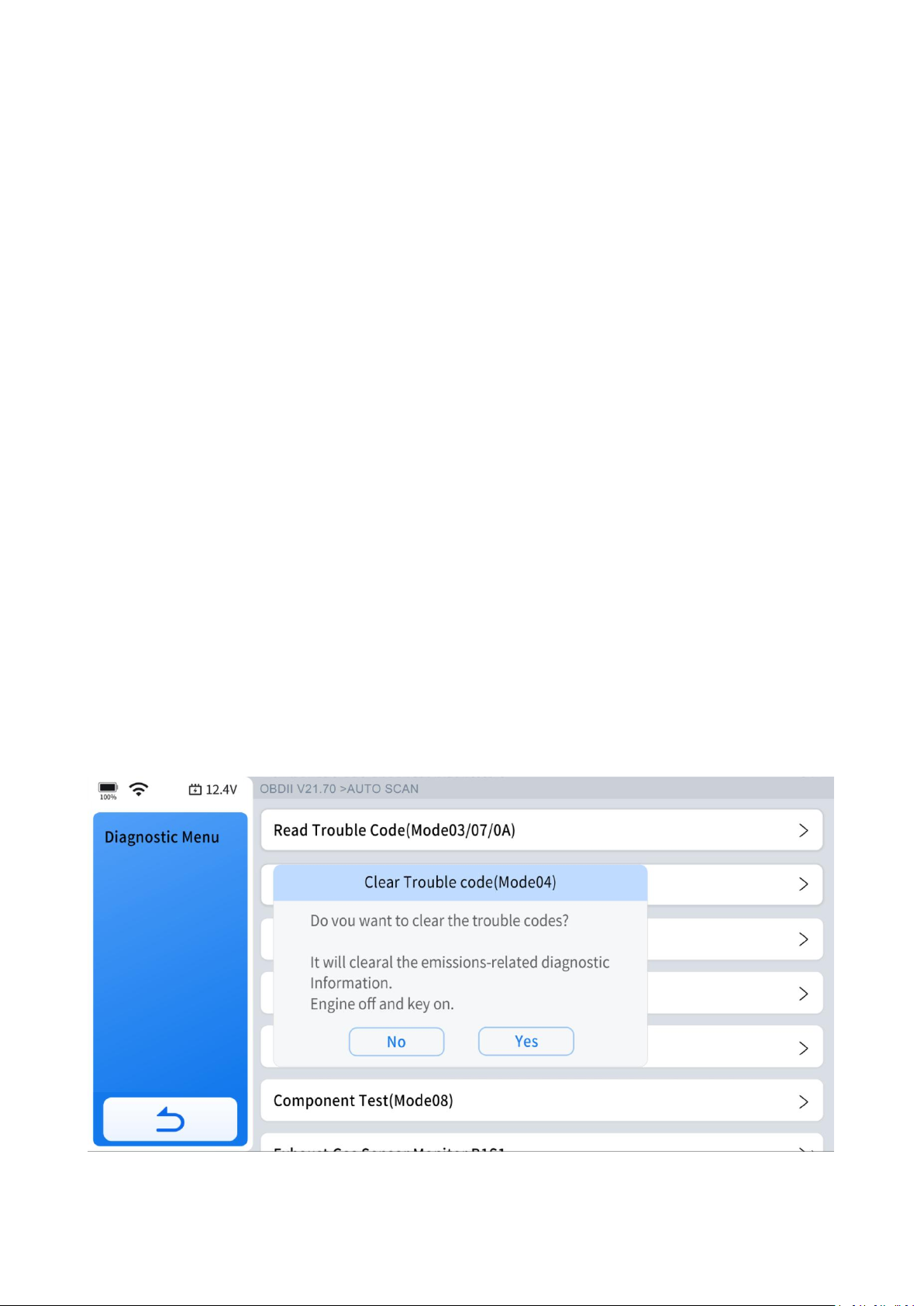
5.5.3 Clear Trouble Code(Mode $04)
This option is designed to erase all emission-related diagnostic data stored in the
memory of the selected ECM. This includes Diagnostic Trouble Codes (DTCs), freeze
frame data, and test results. While OBD-II/EOBD displays generic data only, clearing
codes removes all stored information, including any enhanced codes and freeze
frame details.
When you select the clear codes function, a confirmation screen appears to prevent
accidental data loss. You must choose "Yes" on the confirmation screen to proceed
with the operation.
Page 44
35
5.5.4 Live Data(Mode $01)
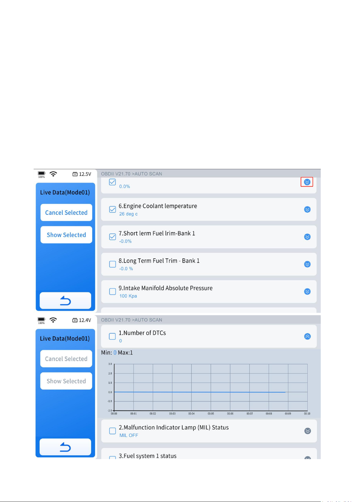
Use this function to view current emission-related data from the selected electronic
control module (ECM) of the vehicle. The main screen layout consists of two primary
columns: the left-hand column provides descriptions of each parameter, while the
right-hand column displays the corresponding parameter values along with their
units or states.
5.5.4.1 View Waveform Chart
Click the circled area in the diagram to view the waveform chart for each data
stream.
Page 45
36
5.5.4.2 Select Live Data
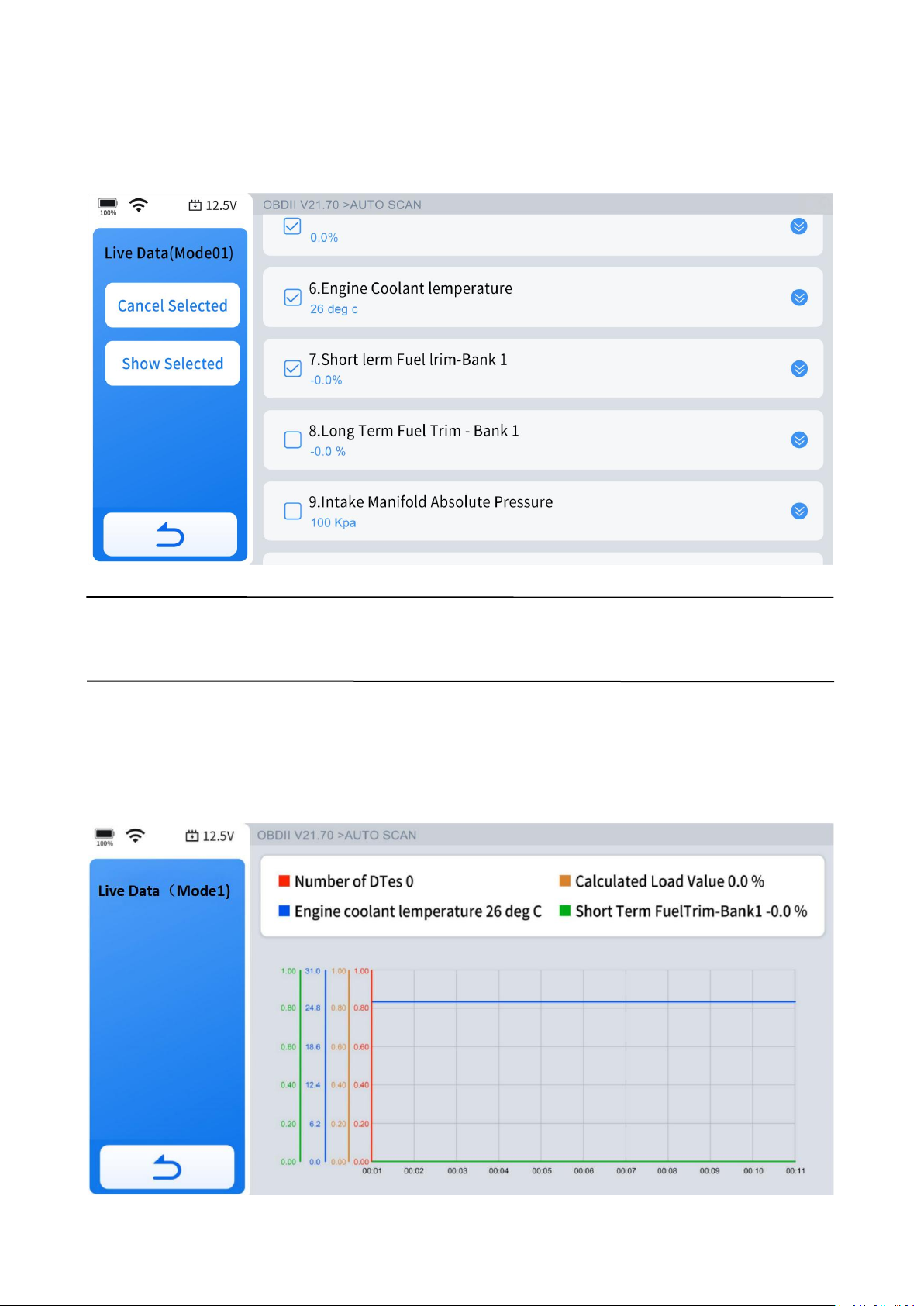
After selecting the data streams you want to view, click "Show Selected" to display
only the selected data streams, without interference from other data streams.
NOTE:
You can select up to four data streams at a time.
5.5.4.3 4-IN-1 Live Data
Select the data streams you want to view, click "Curve Combinatior," and you will get
a combined four-in-one graphical data stream.
Page 46

37
5.5.5 Read Freeze Frame(Mode $02)
Freeze frame data provides a snapshot of critical parameter values at the moment a
diagnostic trouble code (DTC) is set. This function allows you to display freeze frame
data for any stored emission-related DTC. Typically, the stored freeze frame data
corresponds to the last DTC that occurred.
However, for certain DTCs that have a significant impact on vehicle emissions,
priority is given. In these cases, the highest priority DTC is the one for which the
freeze frame records are retained, ensuring critical diagnostic information is
preserved.
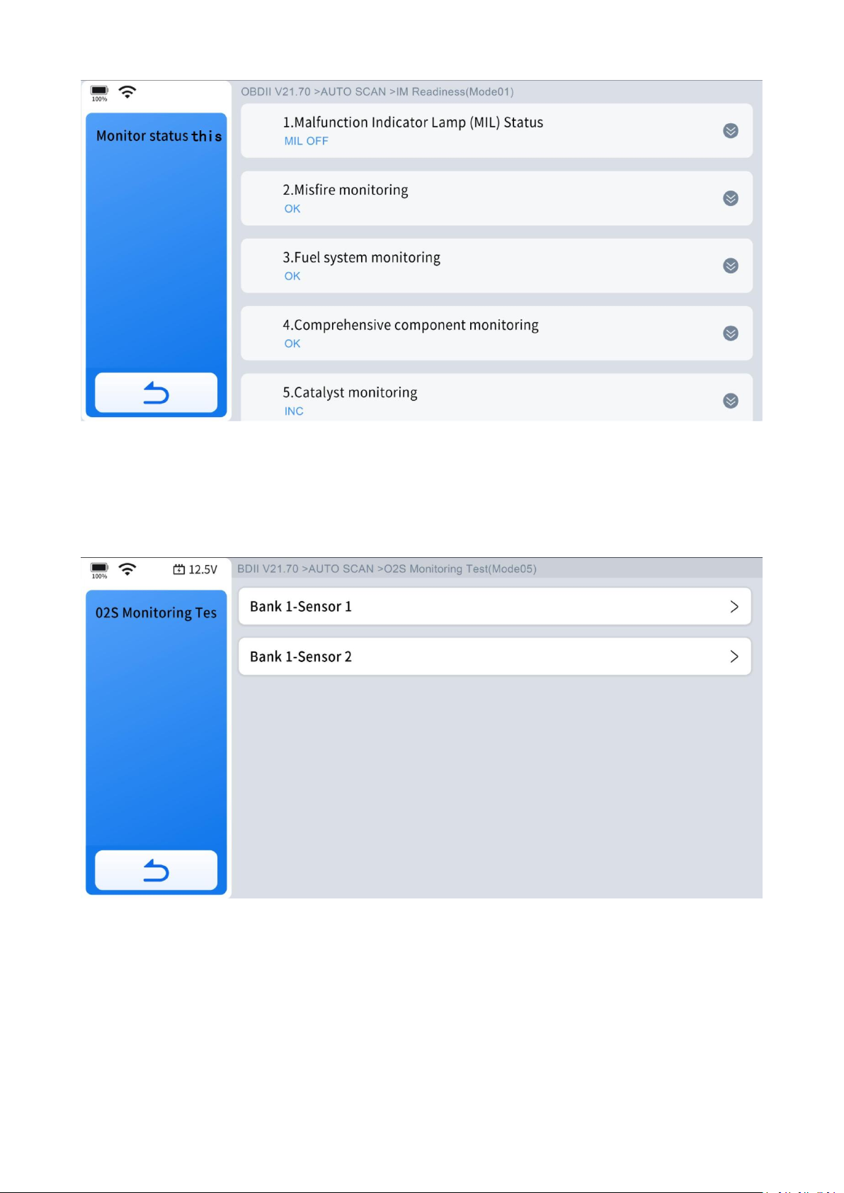
5.5.6 I/M Readiness(Smog Check)
This function is used to check the readiness of the monitoring system. It is an
excellent function to use prior to having a vehicle inspected for compliance to a state
emissions program. Selecting I/M Readiness opens a sub-menu with two choices:
5.5.6.1 Since DTCs Cleared
Displays the status of monitors since the last time the DTCs are cleared.
Page 47
38
5.5.6.2 This Driving Cycle
Displays the status of monitors since the beginning of the current driving cycle.
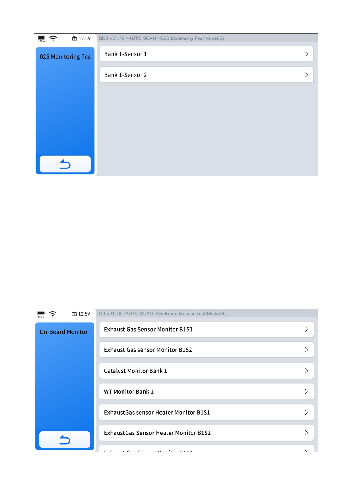
5.5.7 O2S Monitoring Test(Mode $05)
This option opens a menu of tests designed to check the integrity of the oxygen
sensors (O2S). Selecting a test displays all pertinent O2S parameters specific to that
test. The test ID is prominently displayed at the top of the data list.
Page 48
39
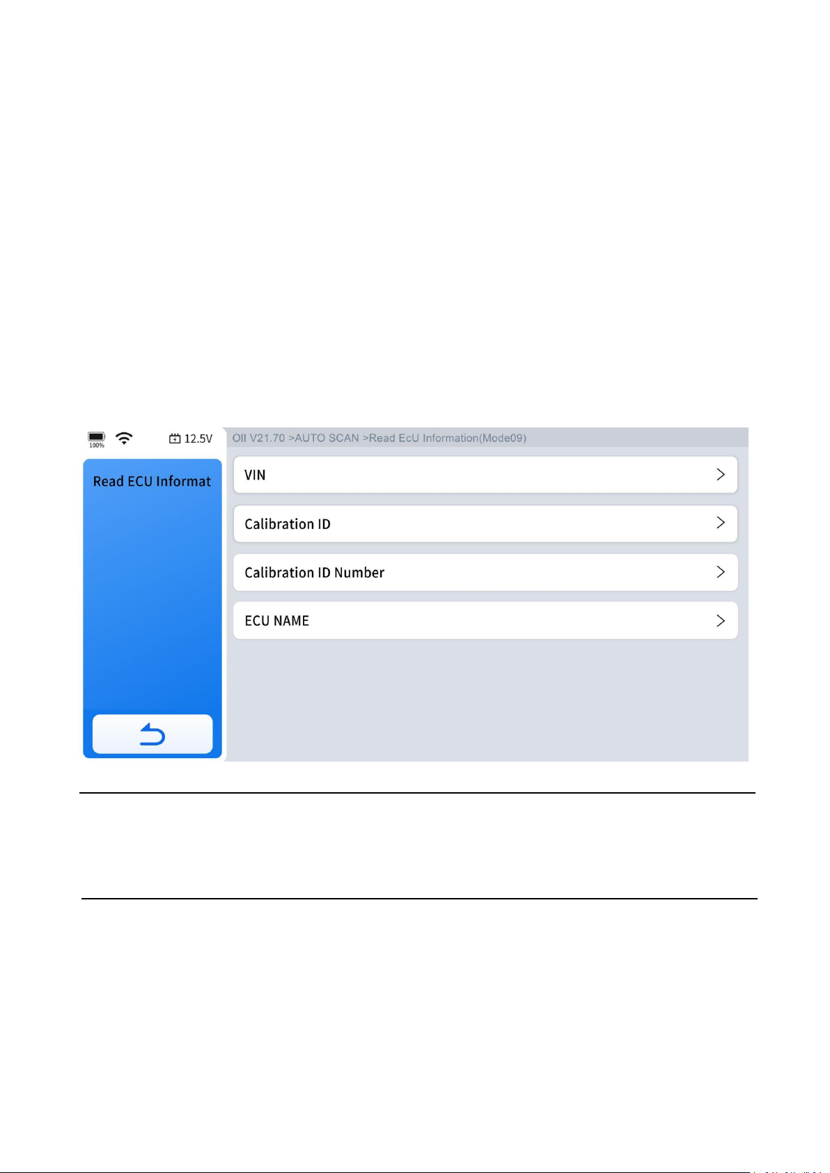
5.5.8 On-Board Monitor Test (Mode $06)
This function allows you to view the results of On-Board Monitor tests. The tests are
useful after servicing or after erasing a vehicle’s control module memory.
The data provided pertains to specific systems and components that the onboard
diagnostic system continuously monitors, such as misfire counters, as well as those it
monitors intermittently. Selecting a specific system or component displays its
corresponding test results.
Page 49
40
5.5.9 Component Test(Mode $08)
This function enables bidirectional control (to limited extend) of the ECM. The
purpose of this function is to allow the Diagnostic Tool to control the operation of an
onboard system, test, or component, such as EVAP leakage test or other test. This
function is useful in determining whether the ECM responds to a command well.
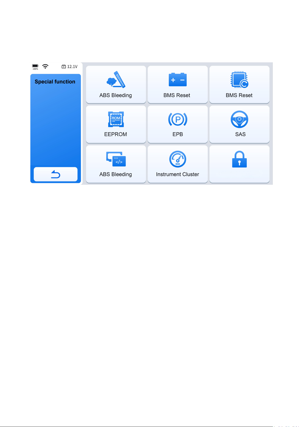
5.5.10 Read ECU Information
This function displays the names of some ECUs (Electronic Control Units) and the
protocols supported by the device. It also provides calibration information for the
device.
IMPORTANT:
Not all vehicles support all service modes, so the available menu selections will vary
accordingly.
6. Special Functions
This chapter details various scheduled service and maintenance functions, also
referred to as "Special Functions." A typical special function screen presents a series
of menu-driven executive commands. By following on-screen instructions to select
Page 50
41
appropriate execution options, enter correct values or data, and perform necessary
actions, the screen prompts will guide you through the complete process for various
special functions.
6.1 Maintenance Light Reset
The Diagnostic Tool can be used to reset the engine oil life system, which calculates
the optimum oil life change interval based on the vehicle's driving conditions and
climate. The oil life reminder must be reset each time the oil is changed so that the
system can calculate when the next oil change is due.
This function can be performed in the following cases:
● If the service lamp is on, you must provide service for the car. After service, you
need to reset the driving mileage or driving time so that the service lamp turns off
and the system enables the new service cycle.
● After changing engine oil or electric appliances that monitor oil life, you need to
reset the service lamp.
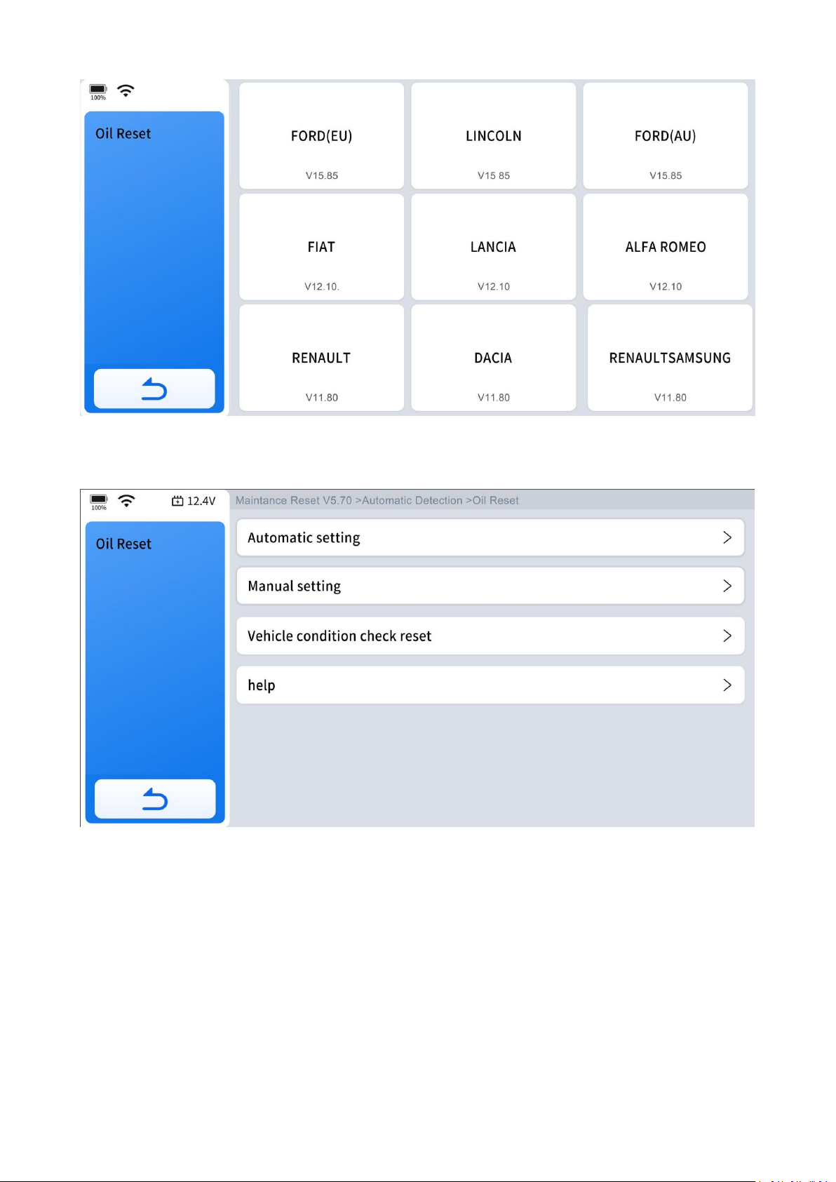
The operation guidelines of the Oil Reset function are shown as below:
Step 1: Enter the Oil Reset menu and select vehicle model according to the vehicle
being tested.
Page 51
42
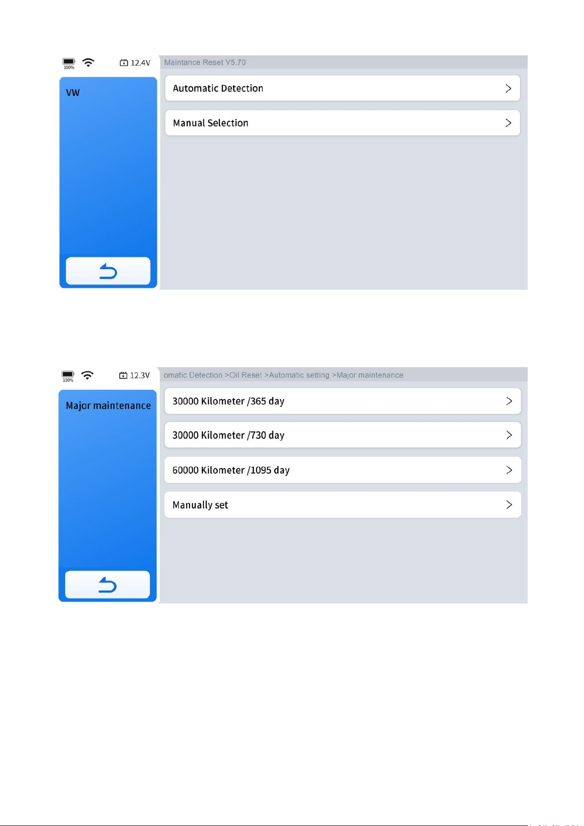
Step 2: Select the appropriate identification method.
Step 3: Enter automatic setting menu.
Page 52
43
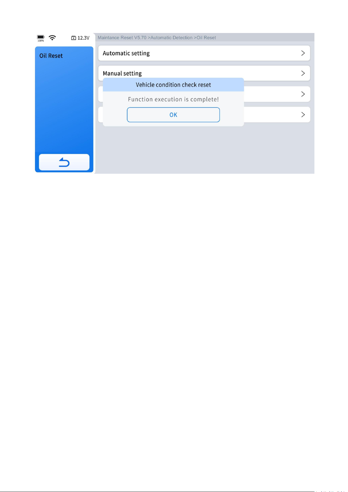
Step 4: Confirm the [New value] you just entered, and then click "OK" at the bottom
right to complete the procedure.
Step 5: Message of "Write successfully" displays when Oil Reset function has been
successfully performed.
Page 53
44
6.2 EPB
1. If the brake pad wears the brake pad sense line, the brake pad sense line will send
a signal to the onboard computer asking for replacing the brake pad. After replacing
the brake pad, you must reset the brake pad to clear the trouble code.
Otherwise, vehicle will continue to falsely notify the driver that the brake pads are in
need of replacement.
2. A reset must be performed in the following cases:
● The brake pad and brake pad wear sensor are replaced.
●
The brake pad indicator lamp is on.
● The brake pad sensor circuit is shorted.
●
The servo motor is replaced.
The operation guidelines of the EPB function are shown as below:
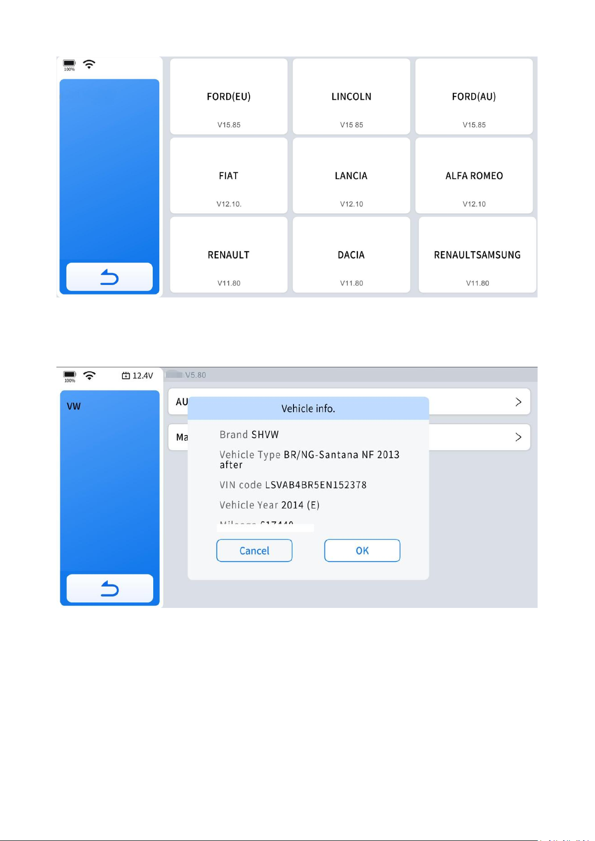
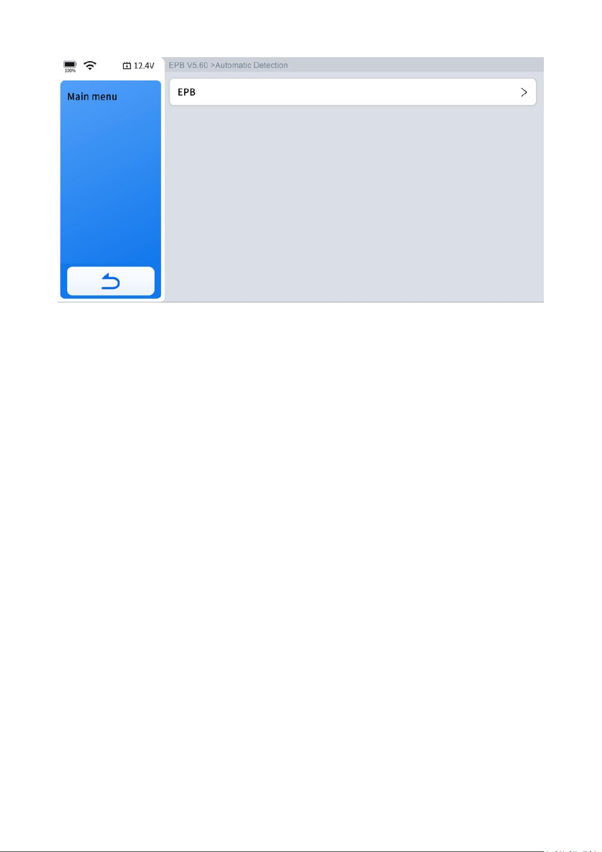
Step 1: Enter the EPB menu and choose relevant models according to the vehicle
being tested.
Page 54
45
Step 2: Ensure your vehicle type.
Step 3: Enter the maintenance mode menu and release the handbrake.
Page 55
46
Step 4: Wait until the message of "Successful operation" pops up. And press "OK" to
exit the menu.
6.3 SAS
Steering Angle Sensors (SAS) System Calibration permanently stores the current
steering wheel position as the straight-ahead position in the SAS EEPROM. Therefore,
the front wheels and the steering wheel must be set exactly to the straight-ahead
position before calibration. In addition, the VIN is also read from the instrument
cluster and stored permanently in the SAS EEPROM. On successful completion of
calibration, the SAS fault codes will be automatically cleared.
To reset the steering angle, you need to first find the relative zero point position for
the vehicle to drive in a straight line. Taking this position as a reference, the ECU can
calculate the accurate angle for left and right steering.
After replacing the steering angle position sensor, replacing steering mechanical
parts (such as steering gearbox, steering column, end tie rod, steering knuckle),
performing four-wheel alignment, or repairing the car body, you must reset the
steering angle.
The operation guidelines of the SAS function are shown as below:
Page 56
47
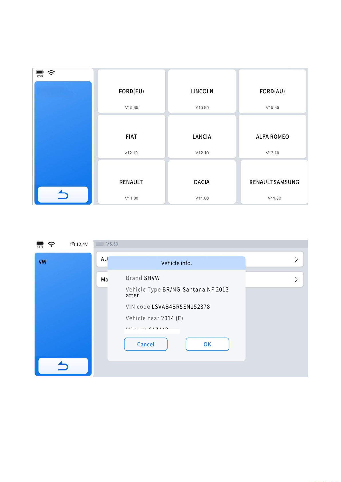
Step 1: Enter the SAS menu and choose the vehicle model according to the vehicle
SAS
being tested.
Step 2: Ensure you vehicle type.
Step 3: Follow the instructions displayed and press "OK" after completing the
instructions shown.
Page 57
48
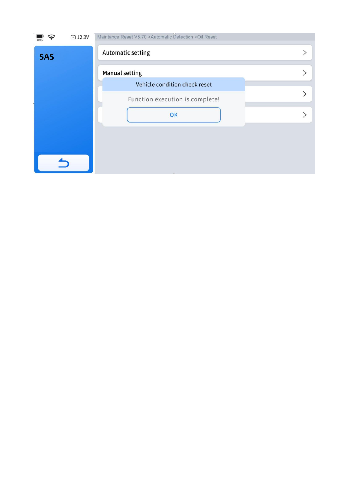
Message of "Function execution is completed" displayed when SAS reset function
has been successfully completed.
6.4 BMS Reset
The Battery Management System (BMS) allows the Diagnostic Tool to evaluate the
battery charge state, monitor the close-circuit current, register the battery
replacement and activate the rest state of the vehicle.
This function enables you to perform a resetting operation on the monitoring unit of
the vehicle battery, in which the original low battery fault information will be cleared
and battery matching will be performed.
Battery matching must be performed in the following cases:
● The main battery is replaced. Battery matching must be performed to clear original
low battery information and prevent the related control module from detecting
false information. If the related control module detects false information, it will
invalidate some electric auxiliary functions, such as automatic start & stop
function, sunroof without one-key trigger function or power window without
automatic function.
Page 58
49
● Battery matching is performed to re-match the control module and motoring
sensor to detect battery power usage more accurately, which can avoid an error
message displayed on the instrument cluster.
The operation guidelines of the BMS Reset function are shown as below:
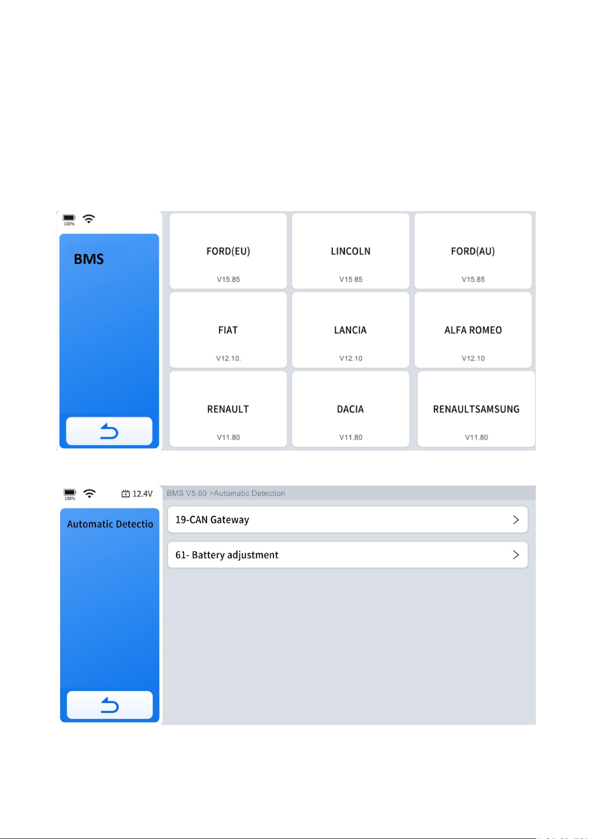
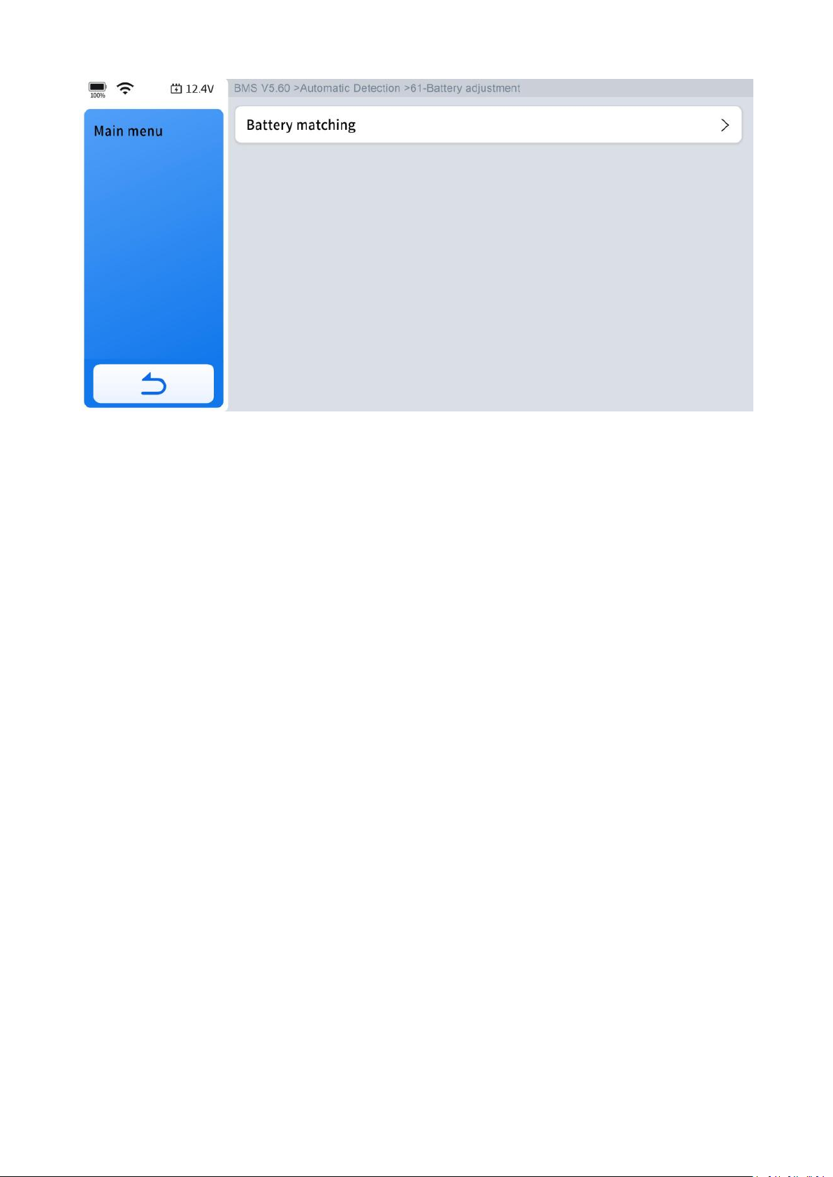
Step 1: Enter the BMS Reset menu and choose relevant models according to the
vehicle being tested.
Step 2: Enter the battery adjustment menu.
Step 3: Click the "Battery Matching" icon.
Page 59
50
6.5 Injector Coding
This function can write the identification code of the fuel injector into the ECU so
that the ECU can recognize the new injector.
After the ECU or injector is replaced, the injector code of each cylinder must be
confirmed or re-coded so that the cylinder can better identify injectors to accurately
control fuel injection.
In general cases, there is no need to perform the coding matching function after
cleaning;
The identification of the fuel injector includes its working accuracy value and type
value. When replacing an injector you need to find the corresponding model for
replacement; At present, mainstream cars support injector coding functions.
The operation guidelines of the Injector Coding function are shown as below:
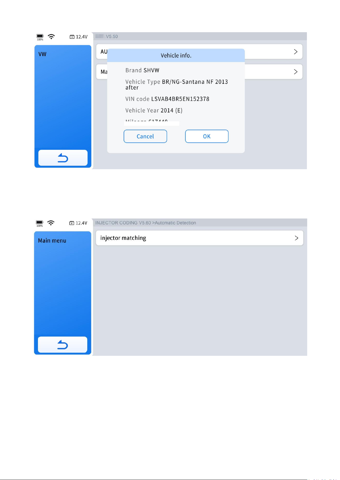
Step 1: Enter the Injector coding menu and choose relevant chassis models
according to the vehicle being tested.
Page 60
51
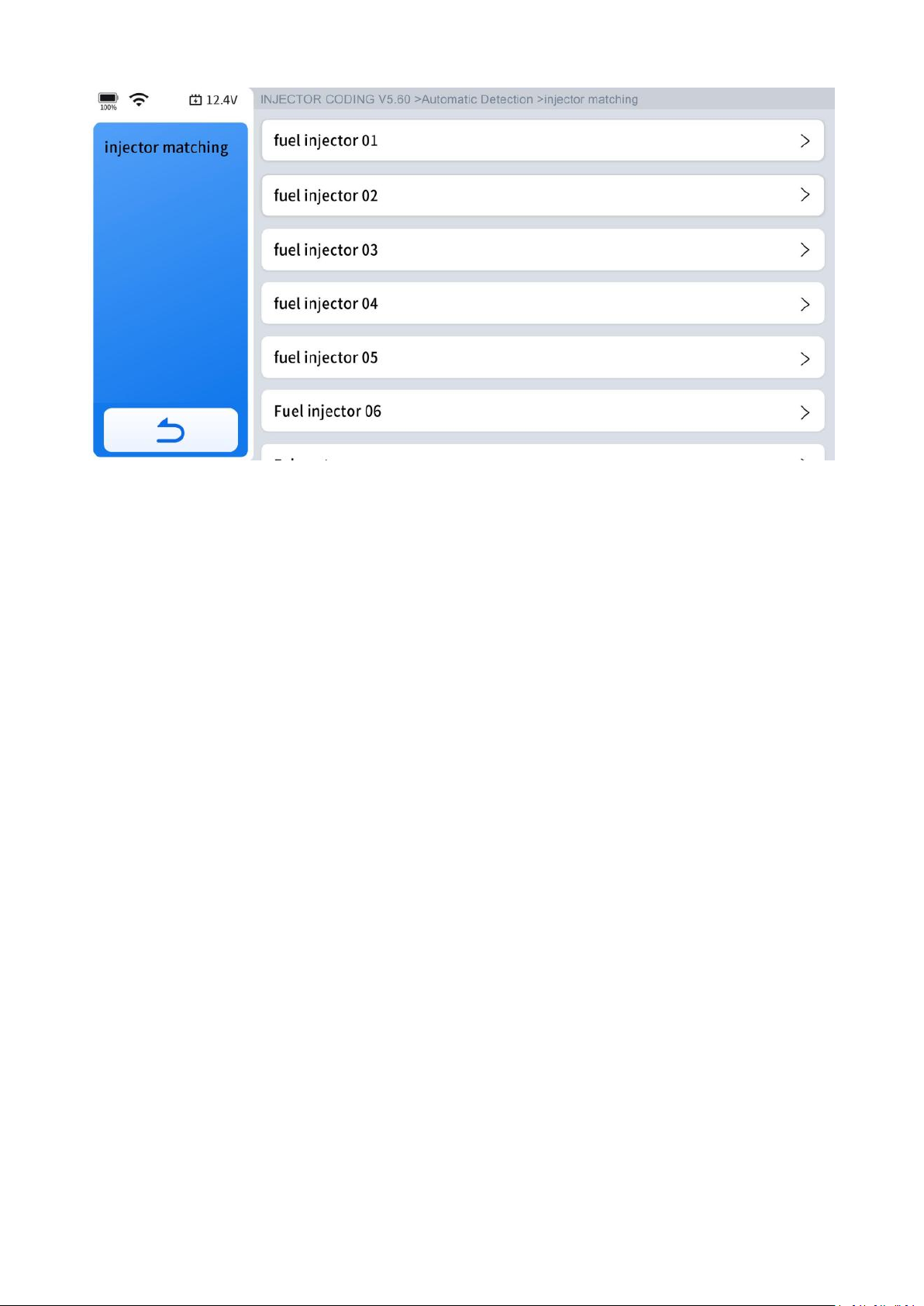
Step 2: Click "injector matching" icon.
Step 3: Select the option that matches your vehicle.
Page 61
52
Wait until the message "Write successfully" pops up means that you have done.
6.6 DPF/GPF
The Diesel Particle Filter (DPF) function manages DPF regeneration, DPF component
replacement teach-in, and DPF teach-in after replacing the ECM.
The ECM monitors driving style and selects a suitable time to employ regeneration.
Vehicles driven a lot at idling speed and low load will attempt to regenerate earlier
than vehicles driven more with higher load and speed. For regeneration to take
place, a prolonged high exhaust temperature must be obtained.
In the event of the car being driven in such ways that regeneration is not possible,
i.e., frequent short journeys, a diagnostic trouble code will eventually be registered
in addition to the DPF light and "Check Engine" indicators displaying. A service
regeneration can be requested in the workshop using the Diagnostic Tool.
DPF regeneration is used to clear PM (Particulate Matter) from the DPF filter through
continuous combustion oxidation mode (such as high-temperature heating
combustion, fuel additive or catalyst reduce PM ignition combustion) to stabilize the
filter performance.
Page 62
53
DPF regeneration may be performed in the following cases:
●
The exhaust back pressure sensor is replaced.
● The PM trap is removed or replaced.
●
The fuel additive nozzle is removed or replaced.
● The catalytic oxidizer is removed or replaced.
● The DPF regeneration MIL is on and maintenance is performed.
●
The DPF regeneration control module is replaced.
The operation guidelines of the DPF function are shown as below:
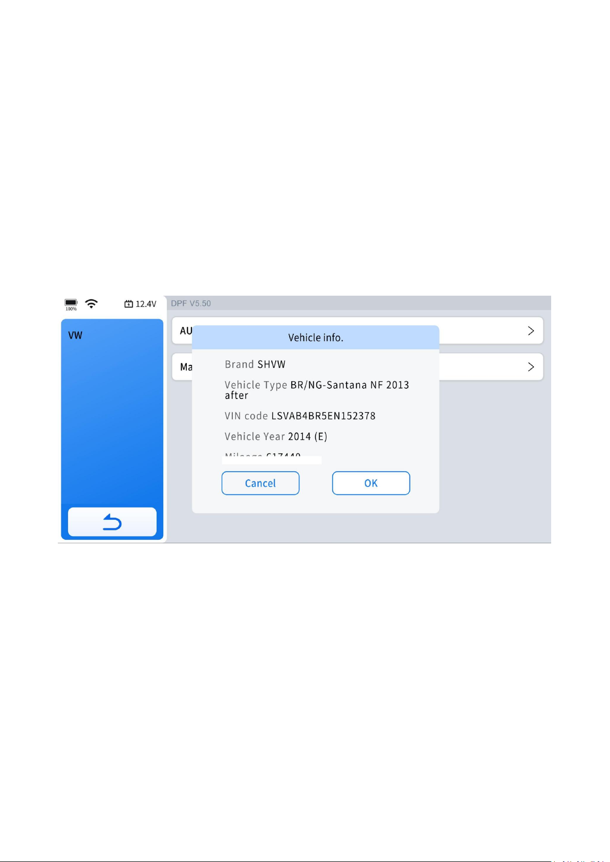
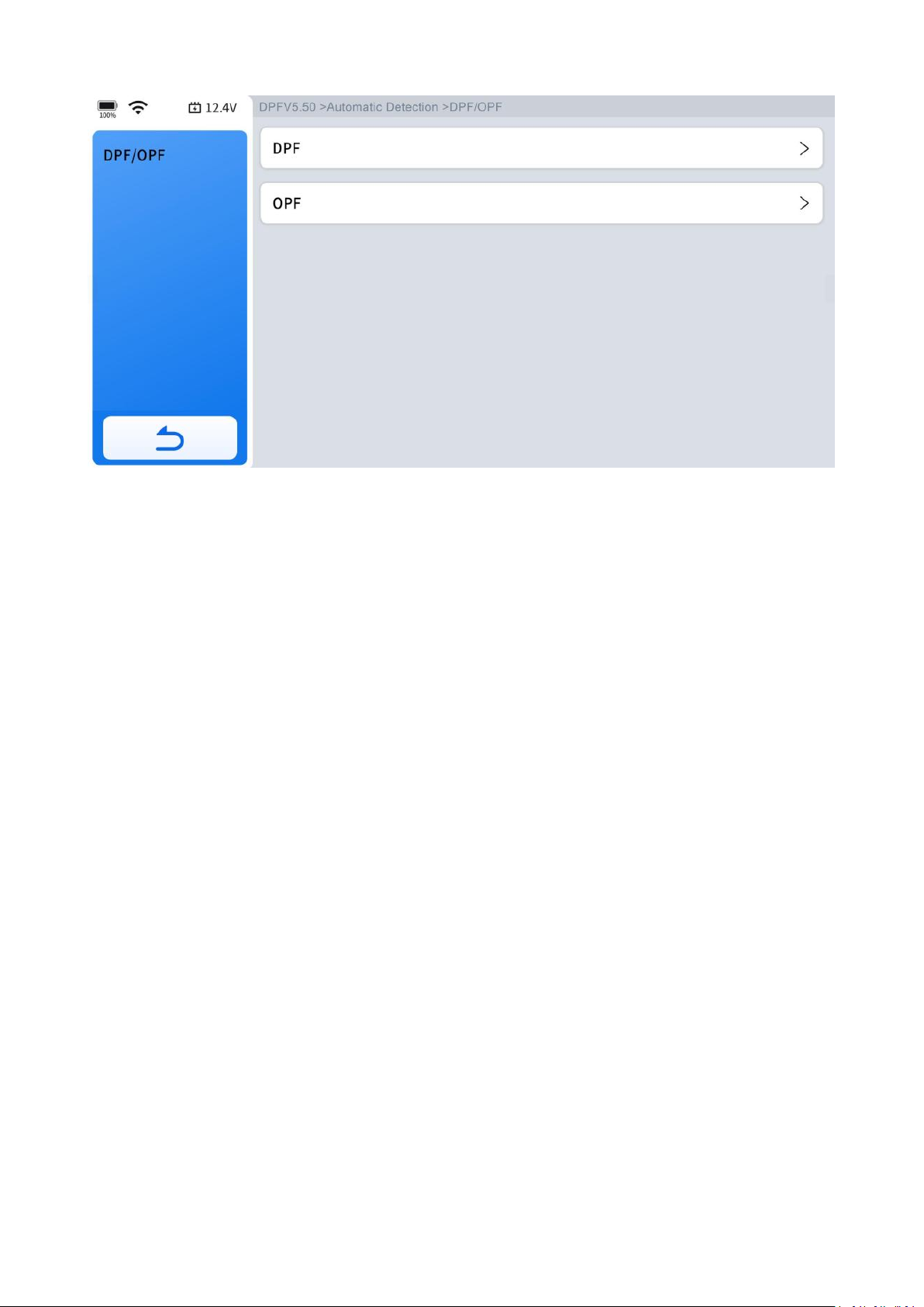
Step 1: Enter the DPF menu and choose relevant models according to the vehicle
being tested.
Step 2: Choose the function you are going to perform.
Page 63
54
Follow the instructions on the device screen until you see a confirmation of
''successful operation.''
6.7 Language Change
This function is to change the system language of the instrument cluster or control
console.
6.8 ABS Bleeding
Anti-Lock Braking System keeps the tires from locking up immediately when there
are brakes. Keeping ABS in good condition can give full play to the effectiveness of
the brakes, shorten the braking time and distance, prevent the vehicle from skidding
and tailing during emergency braking, ensure good driving stability and steering
maneuverability, and avoid violent friction between the tires and the ground to
reduce tire wear. When the ABS contains air, the ABS bleeding function must be
performed to bleed the brake system to restore ABS brake sensitivity. ABS Bleeding
can be performed in the following cases:
● Replace the rear brake distributor pump or the front brake distributor pump
● Severe brake fluid shortage
Page 64
55
● Change the brake fluid
The operation guidelines of the ABS Bleeding function are shown as below:
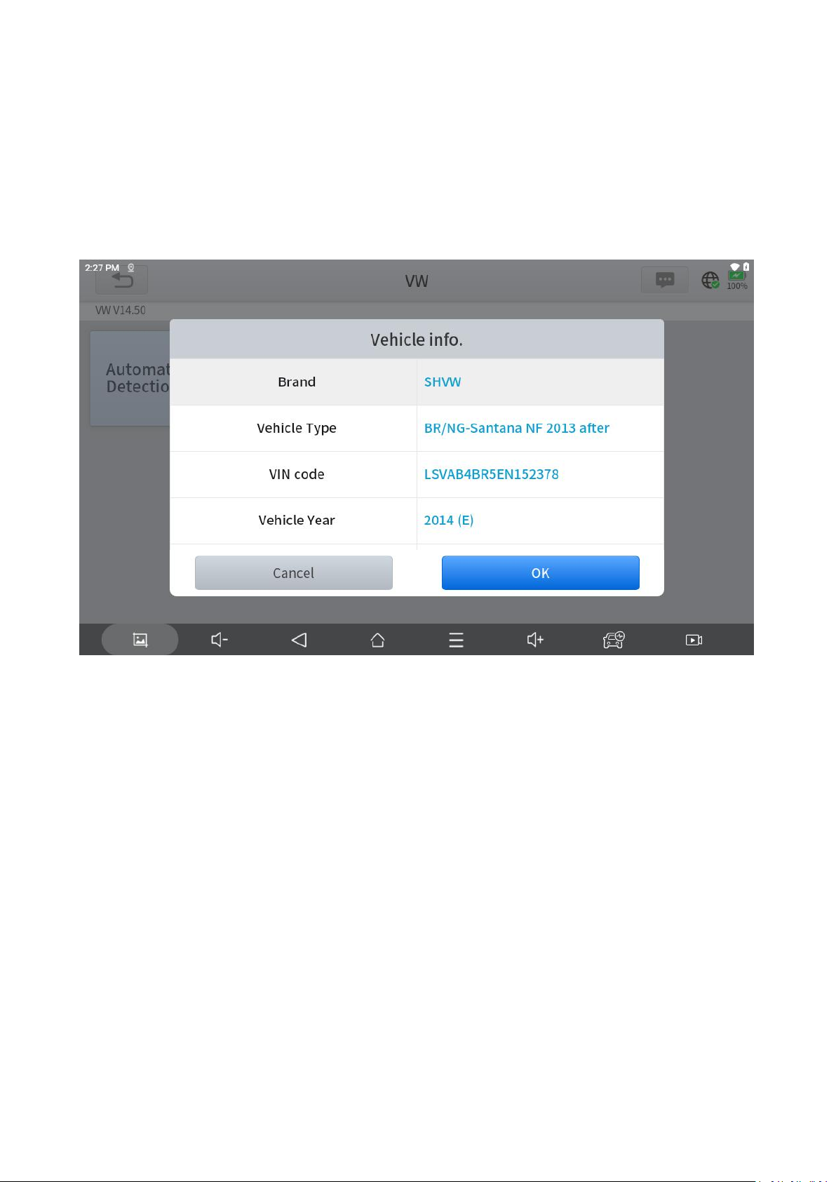
Step 1: Enter the ABS Bleeding menu and choose relevant models according to the
vehicle being tested.
Step 2: Follow the prompt steps and complete the function.
Caution
●
The ABS pump screw needs to be unscrewed.
● Brake fluid will be under pressure during this process. Secure the bleed hose and
open bleeder screws slowly.
● Some vehicles do not support automatic bleeding, but manually bleeding.
6.9 Throttle Matching
Also called Throttle Reset or Throttle Match. This function enables you to reset the
throttle actuators and the learned values stored on ECU to the default state. Doing
Page 65

56
so can accurately control the actions of regulating throttle (or idle engine) to adjust
the amount of air intake.
6.10 A/C Relearn
AC system relearn must be performed when the vehicle AC ECU or actuator is
replaced or the ECU memory is lost.
6.11 Gearbox Matching
This function can complete the self-learning of the gearbox and improve the shift
quality, when the gearbox is disassembled or repaired which may cause shifting
delay or impact.
6.12 Clutch Adaption
This function is to reset the clutch after the replacement of clutch or gear shifting
motor.
6.13 A/F Reset
This function is to reset or relearn the air/fuel ratio parameters.
6.14 NOx Reset
Oxygen sensors and three-way catalysts operate through chemical reactions, and
their performance degrades over time, leading to increased tailpipe emissions.
When these components are replaced, it's crucial to reset the system to ensure they
function properly and maintain emissions within acceptable limits.
Page 66

57
6.15 Headlight Adjustment
Also called Headlight Matching or AFS Reset. This function can initialize the adaptive
headlight system. The headlight system can decide whether to automatically turn on
the headlights based on the ambient light intensity, monitor the vehicle's driving
speed, body posture, etc., and adjust the headlight lighting angle.
6.16 Seat Calibration
Or called Seat Configurations. This function is applied to match or configure the
seats with memory function that are replaced and repaired.
6.17 Disable Transport Mode
During shipment from the factory, a vehicle is put in a partially activate state called
Transport Mode to reduce the drain on the battery. And when it arrives at the
dealership, this function is applied to deactivate or disable the Transport Mode.
6.18 Stop/Start Reset
This function is used to open or close the automatic Start/Stop function via setting
the hidden function in ECU (The precondition is vehicle equipped with hidden
function and hardware is in place).
6.19 Windows Initialization
When the vehicle battery is disconnected, the windows may not work right. This
function is used to perform door window matching to recover the ECU initial
memory, and recover the automatic ascending and descending function of power
window.
Page 67

58
6.20 Rain/Light Sensor
This function is to reset the rain/light sensor after the replacement of the rain/light
sensor or the front windshield.
6.21 EGR Relearn
Also called EGR Adaption. This function is used to learn the EGR (Exhaust Gas
Re-Circulation) valve after it is cleaned or replaced.
6.22 Suspension System
This function can adjust the vehicle body height sensor for level calibration after
replacing the vehicle height sensor or control module in the air suspension system,
or when the vehicle level is not correct.
6.23 SRS
This function is to reset the acceleration sensor when it's replaced or it's providing
wrong data which is used for SRS system, anti-theft system or navigation system.
7. More
This chapter covers the settings for the diagnostic software or tablet, including the
tablet's language, units used in the diagnostic program, USB port mode
configuration, and more.
7.1 My Account
Go to "More"> "Profile"> "Account" to check your email address and change your
password.
Page 68
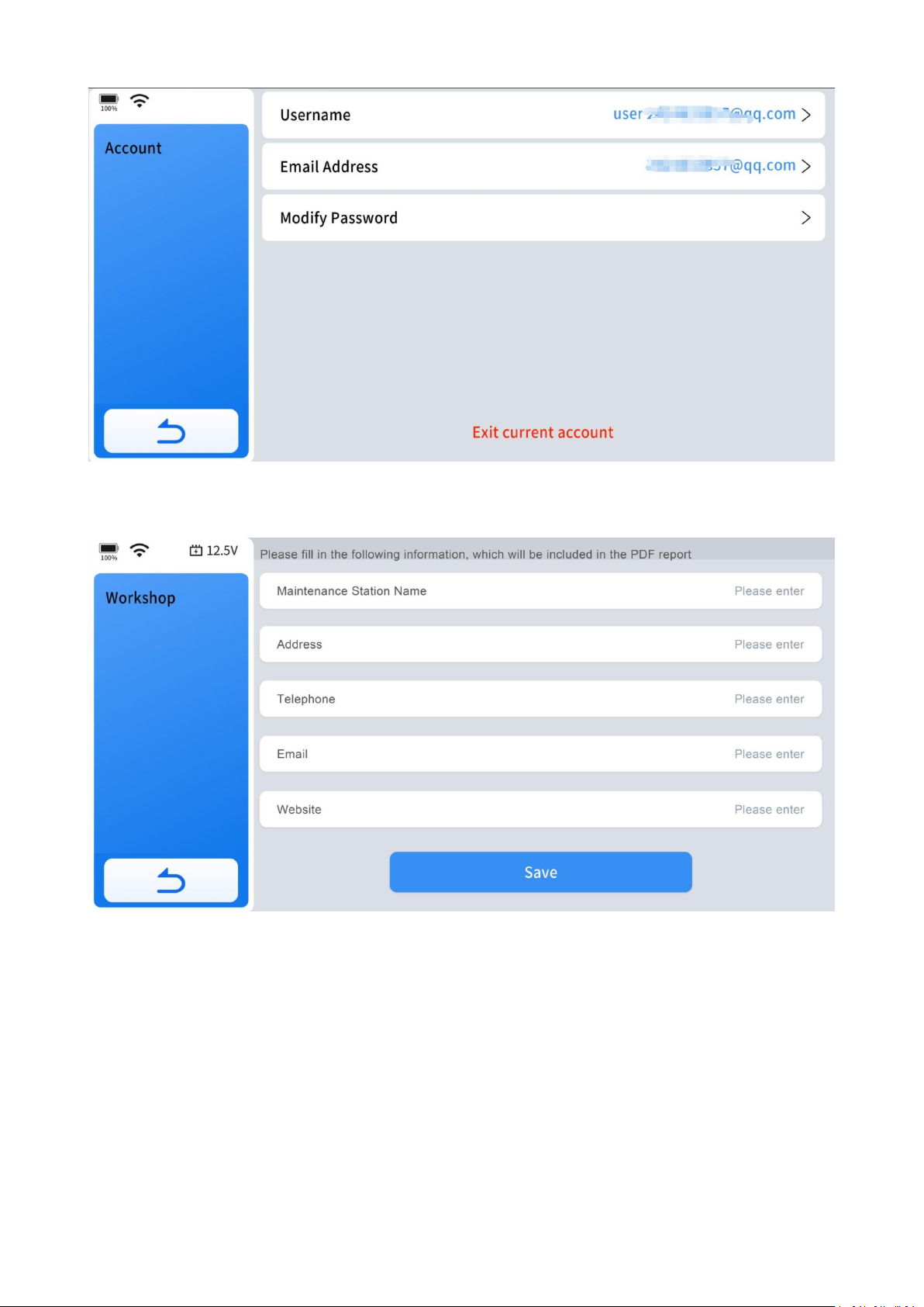
59
Go to "More"> "My Account"> "Workshop" to add your job information if needed.
7.2 Diagnostic Report
Here you can view all historical diagnostic reports, you can select the report you
want to view based on the date of each report.
Page 69
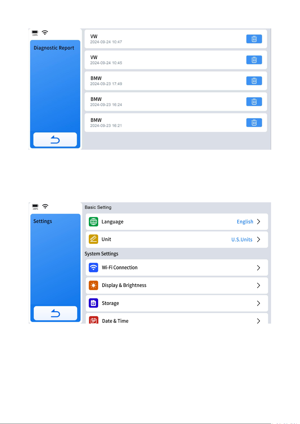
60
7.3 Settings
It covers the settings for the diagnostic software or tablet, including the tablet's
language, units used in the diagnostic program, and more.
7.3.1 Language
This function allows you to modify the language you need, so you won't have any
language problems during use.
Page 70
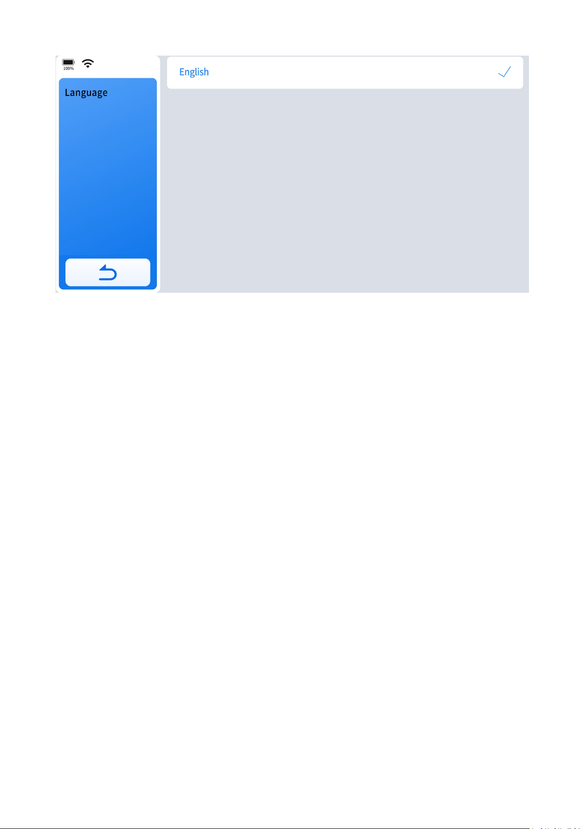
61
Here are the detailed steps:
(1) Contact Your Dealer: Provide your tablet's Serial Number (S/N) to your dealer
and specify the desired language.
(2) Factory Data Reset: More> Settings> About>Factory Data Reset
(3) Log in Again with Your Registered Account.
(4) Remove English Diagnostic Software.
(5) Choose the Language You Preferred: More> Settings> Language> Choose The
Language You Want
(6) Re-download the Software in the Language You Have Chose.
7.3.2 Unit
This setting provides 3(three) sets of units to measure various sensor values.
Page 71
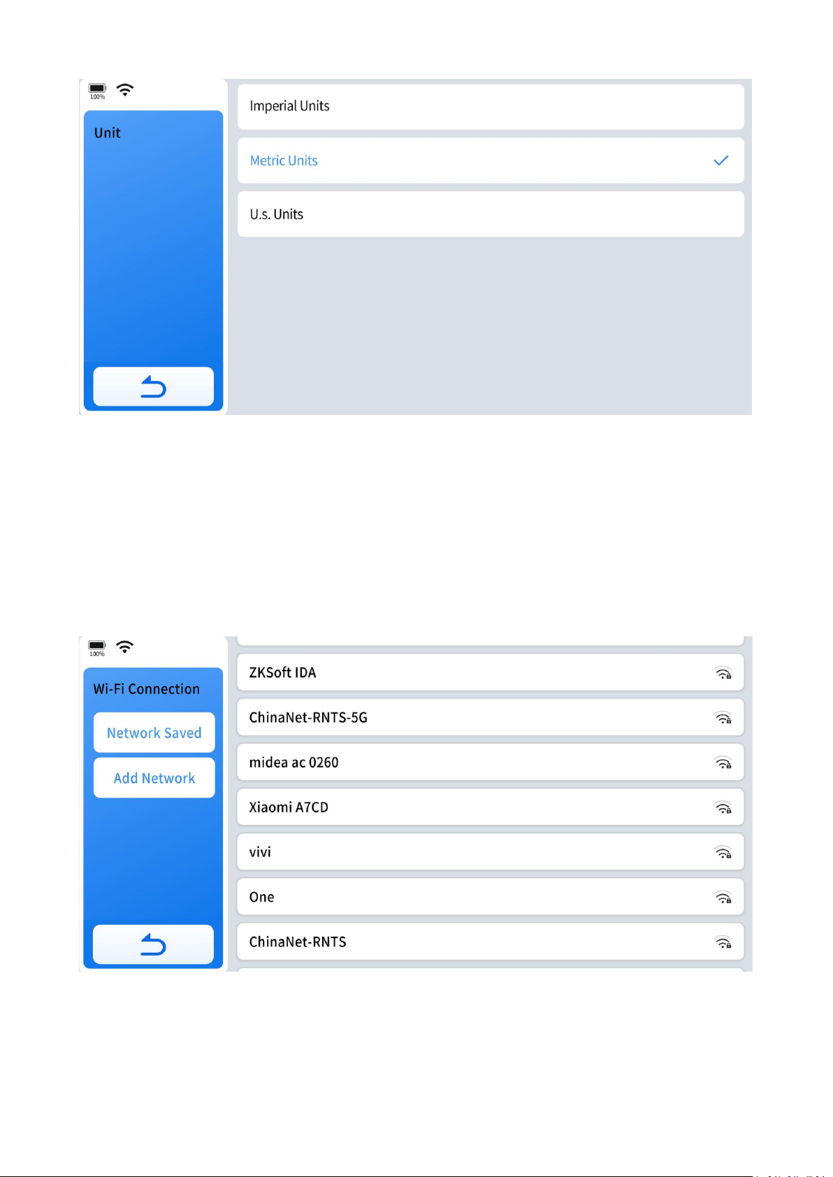
62
Metric Units: Centimeters, kilometers, grams, kilo,℃,litres, pa, kpa
Imperial Units: Inch, foot, yard, oz, lb, ℉,PSI, mile, galon
US Units: Inch, foot, yard, oz, lb, ℉, PSI, mil, mile
7.3.3 Wi-Fi Connection
Here you can change the available Wi-Fi to ensure network speed.
7.3.4 Display & Brightness
Here you can adjust the screen brightness and the sleep time.
Page 72
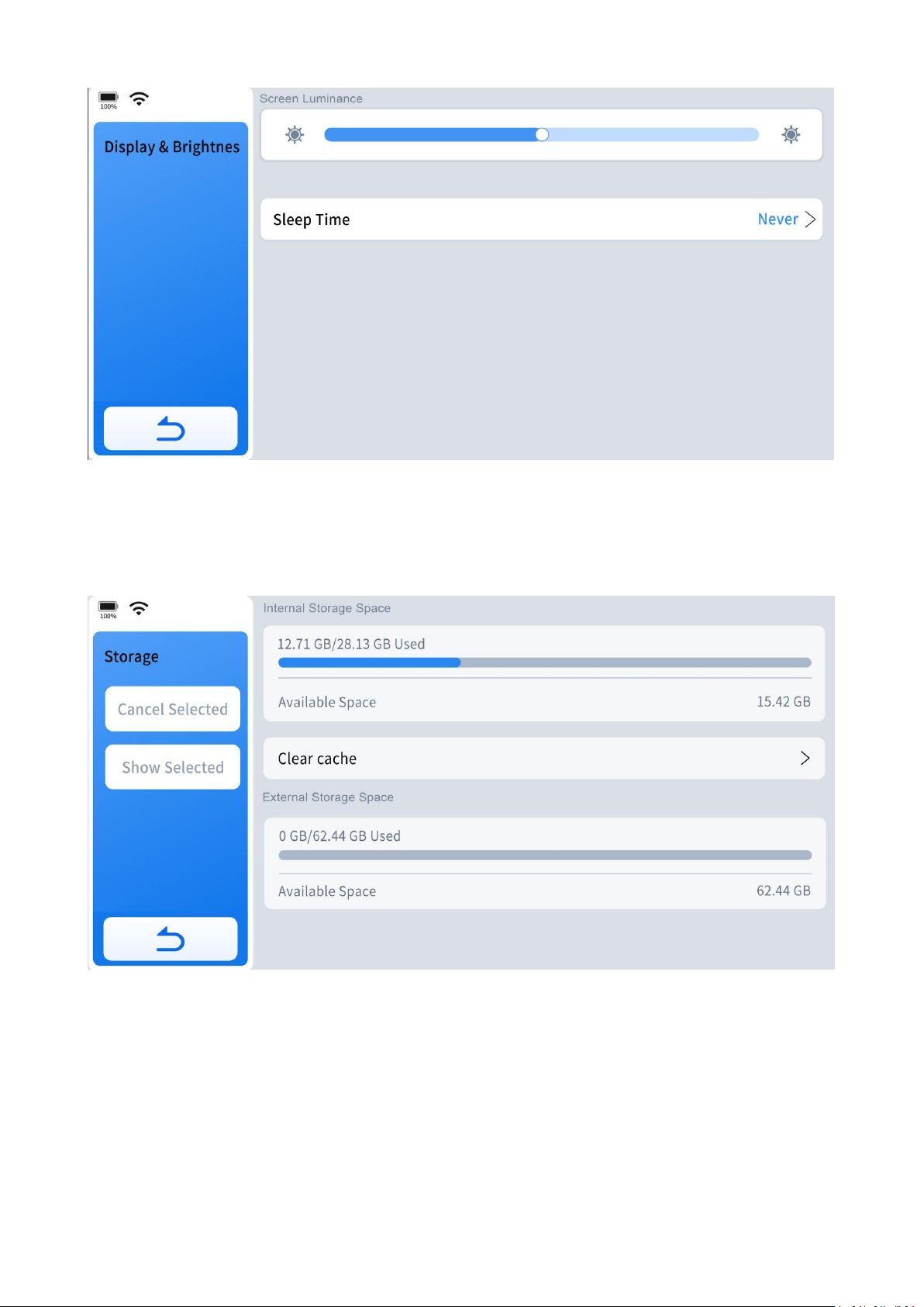
63
7.3.5 Storage
Here you can check the storage space status of your device and clear cache.
7.3.6 Date & Time
Here you can select the time zone and choose 12-hour or 24-hour format.
Page 73
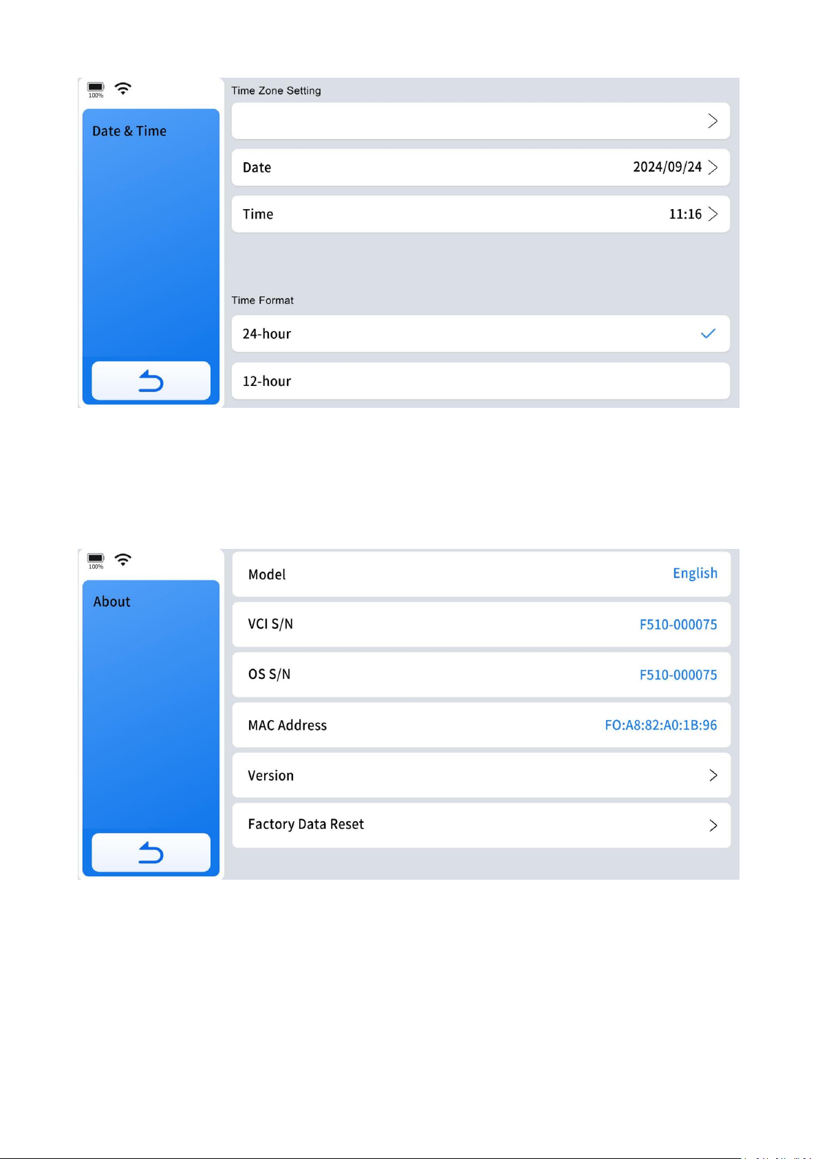
64
7.3.7 About
Here, you can view the device name, serial number, firmware version, device version,
and restore the device to factory settings.
Page 74
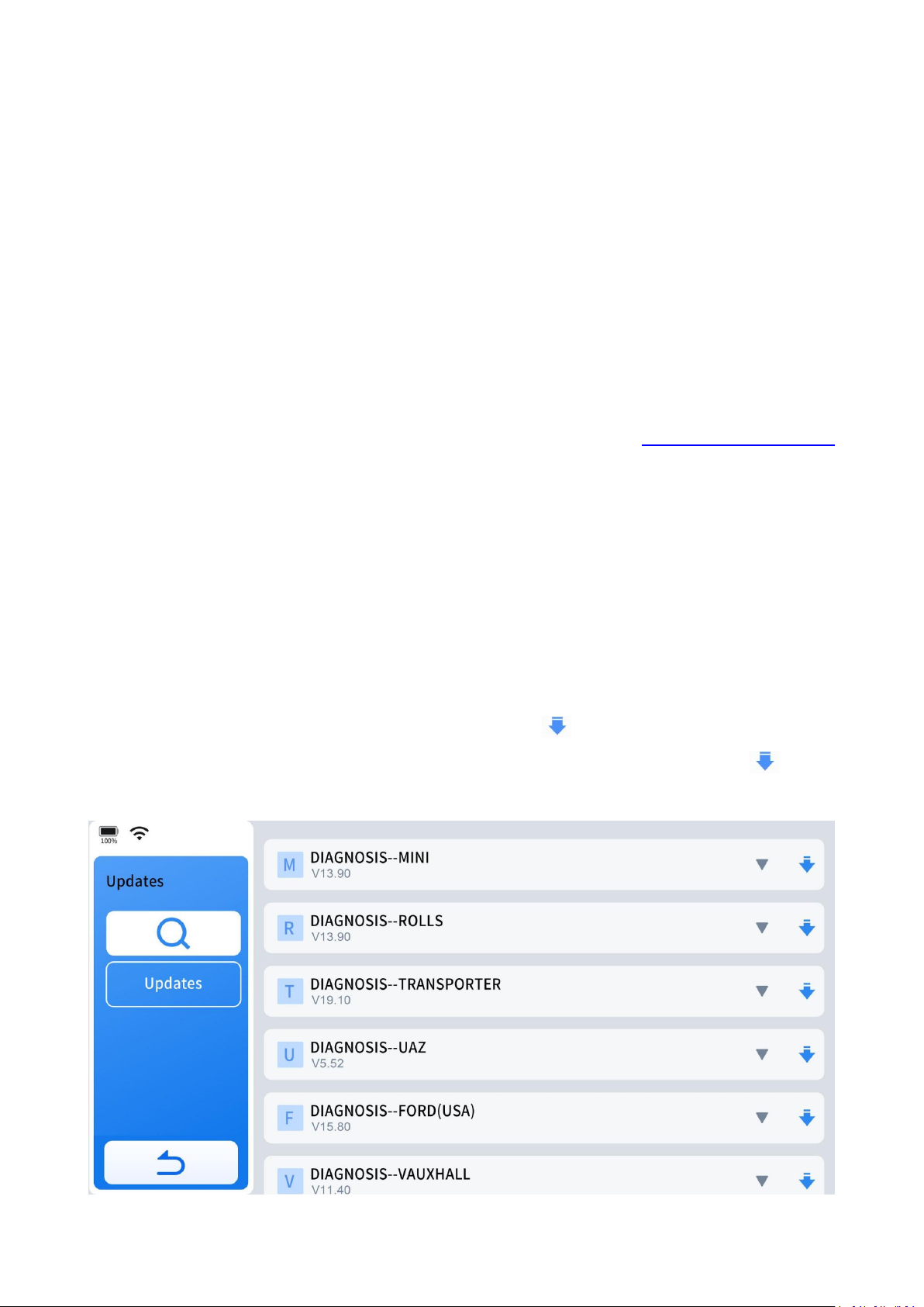
65
8. Software Updates
This chapter details how the software subscription operates and outlines basic
procedures for software updates.
Software updates can be performed while connected to a Wi-Fi network or using a
mobile phone's hotspot. Using a mobile phone's hotspot is recommended in case of
network provider restrictions or when home Wi-Fi is unavailable.
If "Network abnormal" prompt pops up on the screen, try another Wi-Fi or check the
router settings or seek help from our support team via www.xtoolonline.com
/support.
To update the software programs, you have 2 (two) options:
Option 1: Update All Software Programs
Update all by clicking "Update" at the left of the update menu.
Option 2: Update Individual Software Program
Update specific software program by clicking the " " icon at the right side of the
corresponding software program. If the update is interrupted, click the " " icon
again to proceed.
Page 75

66
Delete Software Program:
When the diagnostic tablet has taken up too much memory and become slow, the
solution is to delete the software programs you rarely use to free up some space.
How to delete diagnostic software program:
To delete rarely used diagnostic software program, enter Diagnostic menu and click
on any diagnostic software package for five seconds. When a blank box appears in
the upper left corner of the diagnostic package, check the software package you
want to delete and click "Delete" to remove it.
9.Other Functions
9.1 Print the Report
To view the vehicle diagnostic report anytime, you can send the report to your
phone or computer and print it out.
Here is the step to print the diagnosis report:
Step 1: Send Diagnostic report to your email:More> Diagnostic Report> Choose the
report you want to print> Share by email> Input your email address
Step 2: Receive Diagnostic reports by Email and save them on your phone or your
iPad.
Step 3: Connect your phone or your iPad to the printer and print the Diagnostic
Report.
NOTE:
For the safety of the device's firmware, please avoid connecting it directly to the
printer.
Page 76

67
9.2 Data Logging
For software-related issues such as vehicle communication problems or function
failures, data logging often provides crucial information for successful technical
support sessions.
To ensure we can assist you effectively, please ensure your Diagnostic Tool remains
connected to Wi-Fi for at least 15 minutes. Additionally, provide the Serial Number
(S/N). This allows our technical team to access the data logs from the server and
begin analyzing the issue to find a solution.
9.3 FAQ Database
This section describes how to access our FAQ database on our website. Visit
www.xtoolonline.com and then click "FAQs" or click direct link
https://www.xtoolonline.com /faqs
9.4 Corporate Purchase
Whether you represent a company, school, government agency, or NGOs and you
want to buy in bulk, reach us through email: [email protected] and get a
bulk discount.
9.5 Inventors and Testers Program
That sounds like an exciting opportunity indeed! If you're interested in becoming a
product tester, inventor, or contributing to language improvements in the User
Manual, it's best to reach out to the company directly through their designated
channels. Contacting their support team or customer service would provide you with
more detailed information on how to participate in these specific programs. They
can guide you on the steps to take and any requirements needed to get involved.
Page 77

68
10. Compliance Information
10.1 FCC Compliance / FCC ID: 2AW3IF510
This device complies with Part 15 of the FCC rules and Industry Canada’s
license-exempt RSSs.
Operation is subject to the following two conditions:
1. This device may not cause harmful interference.
2. This device must accept any interference received, including interference that may
cause undesired operation.
Cet appareil est conforme aux CNR exempts de licence d’Industrie Canada.
Son fonctionnement est soumis aux deux conditions suivantes:
1. Ce dispositif ne peut causer des interferences; et
2. Ce dispositif doit accepter toute interférence, y compris les interférences qui
peuvent causer un mauvais fonctionnement de l’appareil.
WARNING:
Making changes or modifications without explicit approval from the responsible
compliance authority may revoke the user's authorization to operate the equipment.
NOTE:
This equipment has undergone testing and meets the requirements for a Class B
digital device, as stipulated by Part 15 of the FCC Rules. These standards are
intended to offer reasonable protection against interference when installed in
residential environments.
This equipment emits radio frequency energy during operation, which can
potentially interfere with radio communications if not installed and used as per the
provided instructions. While efforts are made to minimize interference, there is no
assurance that it will not occur in specific installations. If interference affects radio or
television reception, you can determine if this equipment is the cause by powering it
off and on. To mitigate such interference, consider the following measures:
● Reorient or relocate the receiving antenna.
Page 78

69
● Increase the separation between the equipment and the receiver.
● Connect the equipment to an outlet on a circuit different from that to which the
receiver is connected.
● Consult the dealer or an experienced radio/TV technician for assistance.
10.2 UKCA
(UK Conformity Assessed) is a compliance mark introduced by the UK after Brexit,
intended to replace the previous CE mark. It applies to products sold in the UK
market, ensuring that these products meet the UK’s safety and environmental
standards. This product has been certified with UKCA.
10.3 RF Warning Statement
The device has been evaluated to meet general RF exposure requirement.
The device can be used in portable exposure condition without restriction.
The term “IC” before the radio certification number only signifies that IC technical
specifications were met.
10.4 ROHS Compliance
This device complies with the European RoHS Directive 2011/65/EU, which restricts
the use of certain hazardous substances in electrical and electronic equipment.
10.5 CE Compliance
This product conforms to the essential requirements of the following Directives and
bears the CE mark accordingly:
EMC Directive 2014/30/EU
R&TTE Directive 1999/5/EC
Low Voltage Directive 2014/35/EU
Page 79

70
10.6 ISED
ISED (Innovation, Science and Economic Development Canada) is a Canadian
government department focused on promoting innovation, scientific research, and
economic growth. It develops and implements policies to support businesses,
encourages entrepreneurship, facilitates international trade, and regulates areas
such as telecommunications and consumer protection. ISED aims to enhance
Canada's economic competitiveness and foster a culture of innovation. This product
has been certified by ISED.
11.Warranty
Limited Two-Year Warranty
Shenzhen XTOOL tech Intelligent Co., LTD.(the Company) warrants to the original
retail purchaser of this XTOOL device that should this product or any part thereof
during normal usage and under normal conditions be proven defective in material or
workmanship that results in product failure within two year from the date of
purchase, such defect(s) will be repaired, or replaced (with new or rebuilt parts) with
Proof of Purchase, at the Company’s option, without charge for parts or labor
directly related to the defect(s).
The Company shall not be liable for any incidental or consequential damages arising
from the use, misuse, or mounting of the device.
This warranty does not apply to:
1.Products subjected to abnormal use or conditions, accident, mishandling,neglect,
unauthorized alteration, misuse, improper installation/repair or, improper storage;
2. Products whose mechanical serial number or electronic serial number has been
removed, altered, or defaced;
3. Damage from exposure to excessive temperature or extreme environmental
conditions;
4. Damage resulting from connection to, or use of any accessory or other product
not approved or authorized by the Company;
Page 80

71
5. Defects in appearance, cosmetic, decorative, or structural items such as framing
and non-operating parts;
6. Products damaged from external causes such as fire, dirt, sand, battery leakage,
blown fuse, theft, or improper usage of any electrical source.
12. Appendix
12.1 Navigation Path Quick Check
Misfire Counters: Auto Identification> ISO 15765-4 Module $000007E8> On-Board
Monitor Test> Misfire Cylinder 1 Data> Misfire count for last/current driving cycles
Fuel Loop Status: Go Diagnostic> Region> Make> Model> Year> System Selection>
Full System Diagnosis> Engine Electronics> Live Data> Packet Data flow> Status of Oil
Pressure Switches
Readiness Status(Smog Check): OBD-II> I/M Readiness Status
Transmission Oil Temperature: Go Diagnostic> Region> Make> Model> Year> System
Selection> Full System Diagnosis>Transmission> Live Data> Transmission Fluid
Temperature Filtered
12.2 Terms & Terminology Quick Check
LTFT= Short for Long Term Fuel Trim
STFT= Short for Short Term Fuel Trim
MIS= Short for Misfire
I/M Readiness Status= Technical term for Smog Check
VGT Turbo Actuator Calibration= Turbo Actuator Pre-Align/Self Calibrate
Cam Crank Relearn= Cam Pattern Relearn
Crankshaft Position Variation Learn= Crankshaft Relearn= CASE Learning= Gear
Learning
Actuation Test= Active Test=Component Test= Bi-Directional Control
Page 81

72
12.3 FAQs
Q1: I haven't found I/M readiness in the menu.
A: Click the "OBD-II" icon >Auto Scan/Select OBD-II Protocol>I/M Readiness
Q2: Unable to find live sensor data as the generic OBD2 scanner, like
short-term/long-term fuel trim.
A: Click the "OBD-II" icon >Auto Scan/Select OBD-II Protocol>Live Data>LTFT, STFT or
similar term .
Q3: Unable to find the misfire data for my Ford/Dodge/Chrysler/Jeep cars?
A: OBD-II >Auto Scan or Select OBD-II Protocol for your car>On Board Monitor
Test>Select "Misfire Cylinder Data" or similar term.
Q4: I can not charge the battery now. I plugged in the cord, it's not charging. The
battery is almost dead, only about 10% left.
A: 1. Try to use the original charging cable or OBD test cable to charge the device for
more than six hours. (Using the original charging cable to connect the power supply
with a stable 12V voltage is preferred)
2. Hold down the shutdown button for 15 seconds and observe whether the device
can be turned on normally. (Do not connect the charging cable)
1. Connect the device to the computer through the USB cable to see if the device
can be recognized by the computer.
4. If neither of the above methods successfully charges the device, please contact
our technical support: [email protected] and send a video showing the
charging issue.
Q5: Can scanner tune up car?
A: Sorry, IP500-BMR Diagnostic Tool does not have the capability to tune up car.
Page 82

73
Q6: It was frozen until the battery went flat even I tried the reset button and the
power button.
A: Please make sure you have updated the App to the latest version(To update the
App to the latest, go to More> Setting> About> Version> APP Version to check the
latest App version and update to the latest.). If yes, please reset to factory settings
and check again. If it still does not work, please reach us directly via
[email protected].
Q7: I cannot update, I've tried Wi-Fi and cell phone as hotpot, however, keep
telling me failure connection.
A: This problem could reside with the setting of your router firewall or the network
provider in your region that restricts access to the server, please check if your router
firewall can access the server or not. If the problem still exists, please reach us via
[email protected].
Q8. Why should I connect the scanner to internet once a month?
A: It's a government policy compliant requirement to connect the device to Wi-Fi
once a month to report IP location to prevent the device being used for illegal
activities. If connecting it to Wi-Fi did not solve the issue, please reach us directly via
[email protected] ASAP.
Q9: The auto scan/VIN cannot work on my vehicle.
A: As for auto scan/VIN, it does not cover all vehicles as some vehicles did not store
VIN in the ECU, some VIN is not included in our coverage database, and some
vehicles like Dodge work in "sending command, answering command" mode for
vehicle communication.
You can try below alternative navigation methods:
● Turn on the ignition and not start the engine to try auto scan. For older vehicles,
please turn on the ignition and start the engine and try auto scan.
● Manual input VIN.
● Diagnosis> America/Europe/Asia> Vehicle Selection> Automatic Detection.
Page 83

74
● Diagnosis> America/Europe/Asia> Vehicle Selection> Manually Selection.
Q10: My diagnostic tool cannot connect to Wi-Fi.
A: If it shows "times out", please check your router and make sure that your router
selected WPA2, not WPA3(maximum compatibility), and that it has not blocked the
outgoing network traffic to non-US regions like China. Switching to mobile phone
hotspot will most likely solve the registration issue. You can switch back to home
Wi-Fi for software downloads when activation is done.
The second method is to connect to the Wi-Fi extender. If you have the Wi-Fi main
modem and the extender. You can try to disconnect the diagnostic tool from the
main Wi-Fi and connect it to the internet via the extender.
If it has connected to the internet but shows "connect internet to sync your device",
the problem is that the country and time zone (china time zone) in the Android
system didn't match what the network time zone was (pacific time zone) and is
preventing it from syncing. Please just correct the time zone to pacific time zone by
entering more menu> settings> Date & Time> select time zone.
Q11: When activating the device, shows error message "registration failure" after
entering your email address.
A: Try mobile hotspot (recommended) or a different network to activate.
Q12: Received a used device with a lock screen password, unable to open the
device.
A: Contact our support team with the device's S/N via [email protected] to
resolve the issue.
Q13: Shall I connect my device to the Internet/ Wi-Fi all the time?
A: No it doesn't need an Internet connection all the time. You just need to register it
and download the updates with internet connection. For some special vehicles like
Page 84

75
Peugeot, scan tools need to be connected to the Internet, because it is required by
the manufacturer. It will require internet connection when you are doing some
advanced features like ECU Programming.
Q14: Does your tools can support all the functions on all vehicles?
A: All our tools are comprehensive diagnostic tools that can work on many vehicle
brands, but it cannot do all the functions on all vehicles, just like any other scan tools
in the market, even the factory scanner can only do functions on their own brand.
Because not all vehicles come with the same functions when manufactured and
even the vehicles of the same model might have various configurations.
13. Contact Us
Warranty & Support
E-mail: [email protected]
Website: https://www.xtoolonline.com/
For Wholesale Business or Become our Distributors:
Share us with your friends, join our community to get tutorials, support and more.
Scan QR code below to subscribe to our social media:
TikTok Instagram Facebook
Facebook:
Page 85

76
https://www.facebook.com/XTOOLonline
Instagram:
https://www.instagram.com/xtoolonline/
Tiktok:
https://www.tiktok.com/@xtoolonlineus
YouTube:
https://www.youtube.com/@xtoolonline
Invent with us, test products before they hit market, help us make better products
for everyone:
E-mail: [email protected]
Create social media content, post online and help our community:
E-mail: [email protected]
 Loading...