

XPower 500 Owner's Manual

by
XPower Inverter 500
Owner’s Guide

About Xantrex
Xantrex Technology Inc. is a world-leading supplier of advanced power
electronics and controls with products from 50 watt mobile units to one MW
utility-scale systems for wind, solar, batteries, fuel cells, microturbines, and
backup power applications in both grid-connected and stand-alone systems.
Xantrex products include inverter s, battery chargers, programmable power
supplies, and variable speed drives that convert, supply, control, clean, and
distribute electrical power.
Trademarks
XPower is a trademark of Xantrex International. Xantrex is a registered
trademark of Xantrex International.
Other trademarks, registered trademarks, and product names are the property
of their respective owners and are used herein for identification purpos es
only.
Notice of Copyright
XPower Inverter 500 Owner’ s Guide © February 2006 Xantrex International.
All rights reserved.
Disclaimer
UNLESS SPECIFICALLY AGREED TO IN WRITING, XANTREX TECHNOLOGY
INC. (“XANTREX”)
(a) MAKES NO WARRANTY AS TO THE ACCURACY, SUFFICIENCY OR
SUITABILITY OF ANY TECHNICAL OR OTHER INFORMATION PROVIDED IN
ITS MANUALS OR OTHER DOCUMENTATION.
(b) ASSUMES NO RESPONSIBILITY OR LIABILITY FOR LOSS OR DAMAGE,
WHETHER DIRECT, INDIRECT, CONSEQUENTIAL OR INCIDENTAL, WHICH
MIGHT ARISE OUT OF THE USE OF SUCH INFORMATION. THE USE OF ANY
SUCH INFORMATION WILL BE ENTIRELY AT THE USER’S RISK.
Date and Revision
February 2006 Revision C
Part Number
975-0094-01-01
Contact Information
Telephone: 1 800 670 0707 (toll free North America)
1 360 925 5097 (direct)
Fax: 1 800 994 7828 (toll free North America)
1 360 925 5143 (direct)
Email: customerservice@xantrex.com
Web: www.xantrex.com

Table of Contents
1. Introduction . . . . . . . . . . . . . . . . . . . . . . . . . . . . . . . . . 1
2. Important Safety Information . . . . . . . . . . . . . . . . . . 2
Warnings and Cautions . . . . . . . . . . . . . . . . . . . . . . . . 2
3. XPower 500 Inverter Features . . . . . . . . . . . . . . . . . . 6
AC Outlets . . . . . . . . . . . . . . . . . . . . . . . . . . . . . . . . . 8
4. Connecting the XPower 500 . . . . . . . . . . . . . . . . . . . . 9
Choosing a Location . . . . . . . . . . . . . . . . . . . . . . . . . . 9
Fastening the Inverter to a Mounting Surface . . . . . . . 9
Connecting the XPower 500 to DC Power . . . . . . . . 10
Using the Battery Clip Wire Assembly. . . . . . . . . . 12
Hardwiring the Inverter to the Battery . . . . . . . . . . 14
Disconnecting the Battery . . . . . . . . . . . . . . . . . . . . . 16
Replacing the In-Line Fuse . . . . . . . . . . . . . . . . . . . . 16
5. Operating the XPower 500 . . . . . . . . . . . . . . . . . . . . 17
Operating Statuses. . . . . . . . . . . . . . . . . . . . . . . . . . 17
Interference With Electronic Equipment. . . . . . . . . 19
6. Battery Operating Time . . . . . . . . . . . . . . . . . . . . . . 20
7. Troubleshooting. . . . . . . . . . . . . . . . . . . . . . . . . . . . . 21
8. Specifications . . . . . . . . . . . . . . . . . . . . . . . . . . . . . . . 24
Electrical . . . . . . . . . . . . . . . . . . . . . . . . . . . . . . . . . . 24
Physical . . . . . . . . . . . . . . . . . . . . . . . . . . . . . . . . . . . 25
Regulatory . . . . . . . . . . . . . . . . . . . . . . . . . . . . . . . . . 25
Product Recycling . . . . . . . . . . . . . . . . . . . . . . . . . . . 26
9. Limited Warranty . . . . . . . . . . . . . . . . . . . . . . . . . . . 27
10. Other Xantrex Products . . . . . . . . . . . . . . . . . . . . . 33
iii

iv

1 Introduction
Thank you for purchasing the Xantrex XPower Inverter 500.
The XPower 500 is part of a family of advanced, highperformance power inverters from Xantrex, the leader in the
field of high-frequency inverter design.
Connected directly to a 12 volt battery, the XPower 500
efficiently and reliably powers a wide variety of household
AC products, such as TVs and VCRs, laptop computers,
camcorder and cell phone chargers, compact fluorescent
lights, soldering irons, and small power tools.
The XPower 500 uses reliable solid state power electronics
for years of safe, trouble-free operation and includes
automatic safety monitoring circuitry to protect it from
inadvertent overload conditions.
Read this guide before connecting or using the XPower 500,
and save it for future reference. The main topics in the guide
are:
• Safety information (page 2)
• XPower 500 features (page 6)
• Instructions for connectin g the inverter (page 10)
• Operating guidelines (page 17)
• Troubleshooting information (page 21)
• Specifications (page 24)
• Warranty and service information (page 27)
1
2 Important Safety Information
If the XPower 500 is connected or used incorrectly,
hazardous conditions may be created. Read and save this
safety information, and pay special attention to all Caution
and Warning statements in the guide and on the inverter
itself. Warnings and Cautions are indicated by this symbol:
• Warning statements identify
conditions that could
result in personal injury or loss of life.
• Caution statements identify conditions or practices that
could result in damage to the XPower 500 or other
equipment.
Warnings and Cautions
WARNING: Shock hazard
The XPower 500 generates the same potentially lethal AC
power as a household wall outlet. Do not insert foreign
objects in the inverter’s AC out let or any other openings in
the inverter. Do not open the inverter. Have a qualified
individual complete any service work.
WARNING: Shock hazard
Do not expose the XPower 500 to water, rain, snow, or
spray.
2
WARNING: Risk of fire or explosion
The XPower 500 contains components that tend to produce
arcs or sparks. To prevent fire or explosion, do not install
the inverter in compartments containing batteries or
flammable materials or in lo ca tions that require ignitionprotected equipment.
WARNING: Fire hazard
To reduce the risk of fire, do not cover or obstruct the
ventilation openings. Do not install the XPower 500 in a
zero-clearance compartment. Overhe ating may result.
WARNING: Shock and fire hazard
During installation route all cable/wiring away from sharp
edges and hot surfaces of the engine compartment or
vehicle.
3
CAUTION: Risk of damage to equipment
The XPower 500 is designed to be directly connected to
standard electrical and elect ronic equipm ent in th e manner
described in this guide. Do not connect it to household or
RV AC distribution wiring. Do not connect it to any AC
load circuit in which the neutral conductor is connected to
ground (earth) or to the negative of the DC (battery)
source.
CAUTION: Risk of damage to the XPower
500
Reverse battery polarity (negative connected to positive;
positive connected to negative) will damage the XPower
500, and it will require servicing. Damage caused by
reverse polarity is not covered by your warranty.
4
CAUTION: Risk of damage to rechargeable
appliances.
The output of the XPower 500 is non-sinusoidal. Certain
battery chargers can be damaged if they are connected to
the XPower 500. Two particular types of equipment are
prone to this problem:
• Small battery-operated appliances such as
rechargeable flashlights, shavers, and night lights that
can be plugged directly into an AC receptacle to
recharge.
• Certain battery chargers for battery packs used in hand
power tools. These chargers have a warning label
stating that dangerous voltages are present at the
charger batt ery terminals.
Do not use the XPower 500 with the type of appliances
just described.
CAUTION: Risk of damage due to high
temperatures.
Do not use the XPower 500 in temperatures over 40° C
(105° F). Overheating may result.
5
3 XPower 500 Inverter Features
This section describes the main features of the XPower 500.
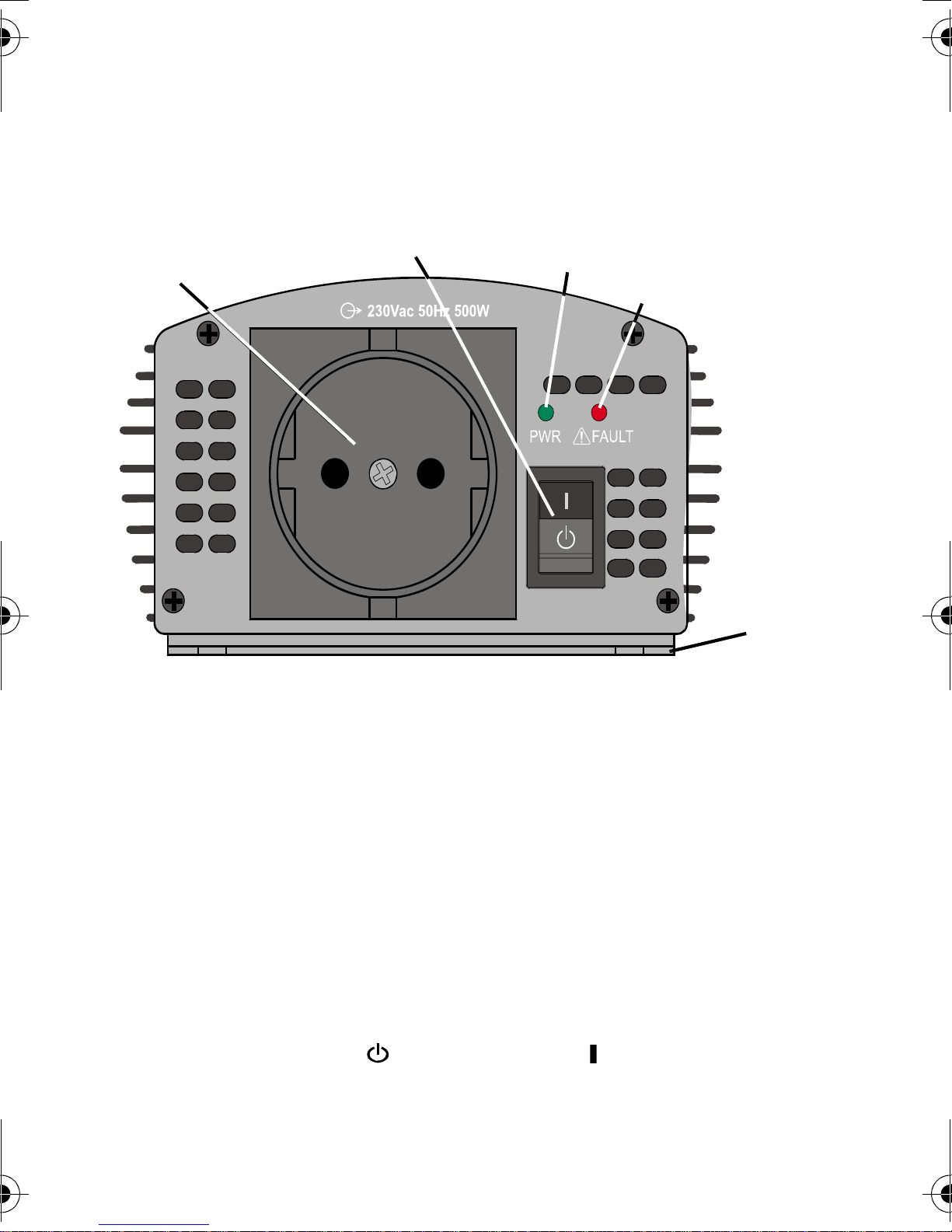
Figure 1 shows the inverter’s AC panel.
2
3
1
4
5
Figure 1 AC Panel on the XPower 500 (European AC Outlet)
1 AC Outlet An AC outlet is located on one end of the
inverter . It allows you to plug in a 230 volt AC product with
a power consumption of 500 watts or less when the inverter
is connected to a 12 volt battery.
The AC outlet on your inverter may be different from the
one shown here. For all available outlets, see Figure 2,
Figure 3, and Figure 4, on page 8.
2 On/Standby Switch The two positions on the On/
Standby switch are: = Standby and = On.
6

When the inverter is connected to a DC power source and
the On/Standby switch is on, AC power is available at the
outlet.
3 Power Light The green PWR light is on all the time
when the On/Standby switch is on.
4 Fault Light The red light indicates that the
inverter has shut down because of low or high battery
voltage, AC overload, or excessively high temperatures.
5 Mounting Flanges Mounting flanges on the AC and
DC ends allow you to mount the inverter permanently. For
additional information, see “Fastening the Inverter to a
Mounting Surface” on page 9.
Audible Alarm An audible alarm warns yo u of a high
temperature shutdown or of an impending low voltage
shutdown.
Fan The fan (see Figure 5) turns on when an AC load of
100 watts or higher is plugged in.
7
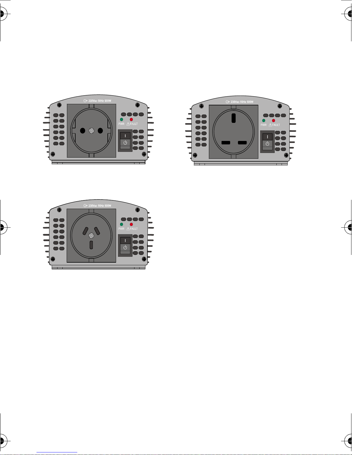
AC Outlets
Depending on your geographic location, your XPower 500
will have one of the following AC outlets.
Figure 2
Figure 4
European AC Outlet
Australian and New Zealand AC Outlet
Figure 3
British AC Outlet
8
 Loading...