

Page 1

PLS600
1. Safety Summary
The following safety precautions apply to both operating and
maintenance personnel and must be observed during all phases
of operation, service, and repair of this instrument. Before
applying power, follow the installation instructions and become
familiar with the operating instructions for this instrument.
Failure to comply with these precautions or with specific
warnings elsewhere in
design, manufacture, and intended use of the instrument.
XP Power assumes no liability for a customer’s failure to comply
with these requirements.
t
his manual violates safety standards of
GROUND THE INSTRUMENT
To minimize shock hazard, the instrument chassis and cabinet must be connected to an electrical ground. This instrument is
grounded through the ground conductor of a three-conductor AC power
approved three-conductor electrical outlet. Do not alter the ground connection. Without the protective ground connection, all
accessible conductive parts (including control controls) can render an electric shock. The power jack and mating plug of the
provided power cable meet IEC safety standards.
DO NOT OPERATE IN AN EXPLOSIVE ATMOSPHERE
Do not operate t
environment constitutes a definite safety hazard.
KEEP AWAY FROM LIVE CIRCUITS
Instrument covers must not be removed by operating personnel. Component replacement must only be made by qualified
maintenance personnel. Removal of the cover will void the warranty. Under certain conditions, even with the power cable
removed, dangerous voltages may exist. To avoid injuries, always disconnect power and discharge circuits before touching
them.
DO NOT SERVICE OR ADJUST ALONE
Do not attempt any internal service. This unit contains no user serviceable components. Removal of the cover will void the
warranty.
he instrument in the presence of flammable gases or fumes. Operation of any electrical instrument in such an
cable. T
he power cable must be plugged into an
DO NOT SUBSTITUTE PARTS OR MODIFY THE INSTRUMENT
Do not install substitute parts o
for service and repair to ensure that safety features are maintained.
r perform any unauthorized modifications to this instrument. Return the instrument to XP Power
Page 2

2. Warnings & Cautions
WARNING and CAUTION statements, such as the following examples, denote a hazard and appear throughout this manual.
Follow all instructions contained in these statements.
A WARNING statement calls attention to an operating procedure, practice, or condition, which, if not followed correctly,
could result in injury or death to personnel.
A CAUTION statement calls attention to an operating procedure, practice, or condition, which, if not followed correctly, could
result in damage to or destruction the product.
WARNING: Do not alter the ground connection. Without the protective ground connection, all accessible conductive parts
(including control controls) can render an electric shock. The power jack and mating plug of the power cable meet IEC safety
standards.
WARNING: Removing t
unless it is done by an authorized service technician.
CAUTION: Before connecting the line cord to the AC mains, check the top cover AC line voltage ratings. Applying a line voltage
other than the indicated voltage can damage the unit. For continued protection, replace fuses only with those of t
voltage and current ratings.
CAUTION: This product uses components which can be damaged by electro-static discharge (ESD). To avoid damage, be sure
to follow proper procedures for handling, storing and transporting parts and subassemblies which contain ESD-sensitive
components.
he instrument cover and/or replacing any internal components will void the warranty of the instrument
he exact same
3. Store/Move/Maintain
Storage
When this power supply is not in use store it in an environment suitable for storage (
Freight
When shipping this power supply, repack it in the original packaging. If the packaging material is lost, use equivalent packing
materials to protect it during shipping.
Maintenance
Please return the power supply to XP Power or an authorized service center for any repair, service, or maintenance.
see specifications page).
Disposal
When the power supply is in an unusable condition and can’t
disposal procedures or local legal procedures. To avoid polluting the environment, please do not discard arbitrarily.
2
be repaired, please discard it according to your company’s
Page 3
Section Content Page No.
1 Safety Summary 1
2 Warnings & Cautions 2
3 Store/Move/Maintain 2
4 Preface 4
4.1 Product Summary 4
4.2 Features 4
4.3 Specification 5
5 Caution Before Using 7
5.1 Check and confirm accessories before using 7
5.2 Operating instructions 7
5.3 Ambient environment 7
5.4 Storage 7
5.5 Power-line voltage 7
5.6 Fuses 7
5.7 Power-off procedure 8
5.8 Low voltage input 8
5.9 Output lead wires and connections 8
6 Front Panel 9
6.1
Front Panel 9
7 Operating Instructions 10
7.1 Normal operation 10
7.1.1 Power on 10
7.1.2 Enabling output 10
7.1.3 Adjusting voltage and current 11
7.1.4 Displaying set points 11
7.1.5 Adjusting over voltage, over current and over power protection 11
7.2 Power Supply Set Up 12
7.2.1 Introduction 12
7.2.2 Mode 14
7.2.3 Auto start setup 16
7.2.4 Remote sense setup 17
7.2.5 Power limit setup 20
7.2.6 Over limits 21
7.2.7 LAN setup 23
7.2.8 Series and parallel operation 24
7.2.9 Calibration 27
Appendix A Analogue control inputs 32
Appendix B USB control input 33
Appendix C Communication over LAN 35
Appendix D Rack mount option 37
Appendix E Error messages 39
Service Information 42
Limited 3 Year Warranty 43
3
Page 4
4. Preface
4.1 Product Summary
The PLS600 is a programmable DC power supply with single output that offers a maximum power output up to 600 watts. With
12-bit D/A & A/D converters embedded, the power supplies come with the capability of reporting voltage and current very
accurately.
The PLS600 series provides convenient digital rotary controls for voltage and current adjustment. The power supplies also c
with rear ports that allow remote control via USB, Ethernet, and analog control inputs. The USB and Ethernet inputs are SCPI
compliant and have LabView drivers available on the National Instruments website. See Appendix A and Appendix B for details.
The PLS600 series is also LXI certified, details for using this interface can be found in the Programming Manual.
The PLS600 series also provide
power supply. The PLS600 will then execute the programs on command. Details can be found in the PLS600 scripting language
manual.
4.2 Features
1. Output Voltage & Current
ophisticated scripting ability that allow the user to write programs and upload them to the
a s
ome
Model Voltage Current Power
PLS6003033 30 33
PLS6005020 50 20
PLS60010010 100 10
PLS6002005 200 5
PLS6004002.5 400 2.5
2. Rotary Controls
600 W
The digital rotary controls allow both fine and rapid adjustment of the output voltage and current. The controls are velocity
sensitive so that a slow turn of the control allows fine adjustment of voltage or current and rapid turning quickly adjusts voltage
or current over a large range.
3. Precise voltage and current measurement
The PLS600 series also offers the capability to measure
expense and space for extra measuring instruments. This capability is available from the display or the readings may be read
into the controlling device.
4. OVP (over voltage protection), OCP (over current protection) and OPP (over power protection) functions
The over voltage protection (OVP), over current protection (OCP) and over power protection (OPP) features limit the maximum
output current and voltage to avoid damage to the unit under test (UUT).
voltage & current accurately (read back), saving users the extra
4
Page 5
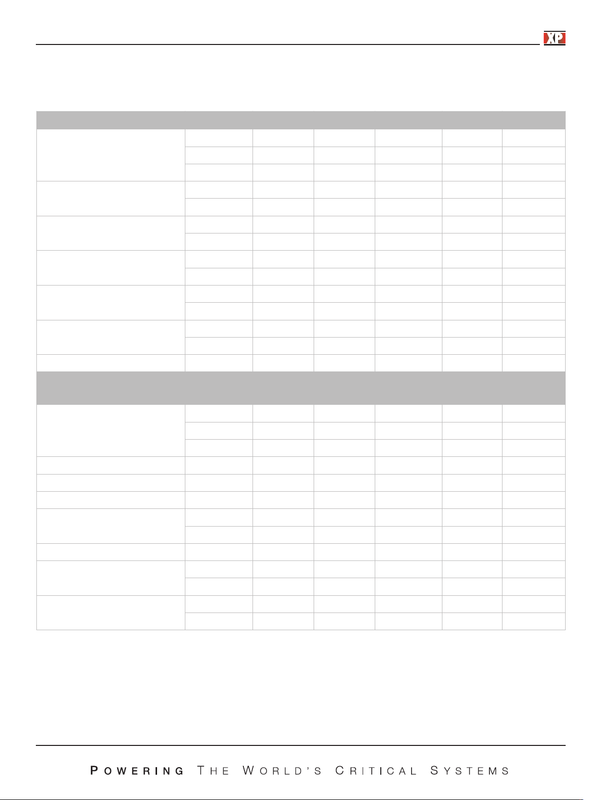
4.3. Specifications
Unless otherwise noted, specifications are warranted over the ambient temperature range of 0 to 40 ºC.
PLS6003033 PLS6005020 PLS60010010 PLS6002005 PLS6004002.5
Voltage 30 V 50 V 100 V 200 V 400 V
DC Output Ratings
(1)
Current 33 A 20 A 10 A 5 A 2.5 A
Power 600 W 600 W 600 W 600 W 600 W
Output Ripple & Noise
CV p-p
CV rms
3
4
60 mV 100 mV 100 mV 100 mV 200 mV
20 mV 100 mV 150 mV 150 mV 50 mV
Load Regulation
(change from 10%-90% load)
Line Regulation
(change from 100-132 VAC input or
180-260 VAC input)
Programming Accurancy
(5)
(1,2)
Voltage 15 mV 25 mV 50 mV 100 mV 200 mV
Current 15 mV 15 mV 15 mA 15 mA 15 mA
Voltage 15 mV 25 mV 50 mV 100 mV 200 mV
Current 15 mV 15 mV 15 mA 15 mA 15 mA
Voltage 0.1%+ 15 mV 25 mV 50 mV 100 mV 200 mV
Current 0.1%+ 66 mA 40 mA 20 mA 10 mA 5 mA
Voltage 0.1%+ 15 mV 25 mV 50 mV 100 mV 200 mV
Measurement Accuracy
Current 0.1%+ 60 mA 40 mA 15 mA 10 mA 5 mA
Transient Recovery Time
(5)
Time ≤1 ms ≤1 ms ≤1 ms ≤1 ms ≤1 ms
Supplemental Characteristics (supplemental characteristics are not warranted but are descriptions of typical performance determind
either by design or type testing)
Output Response Time
(settle to within ±1% of the rated
output, with resistive load)
Command Response Time
Data Readback Transfer Time
Remote Sense Compensation
Over-voltage Protection
Output Ripple & Noise
(3)
Up, Full Load 0.08 s 0.08 s 0.08 s 0.08 s 0.08 s
Down, Full Load 0.08 s 0.08 s 0.08 s 0.08 s 0.08 s
Down, No Load 0.5 s 0.5 s 0.5 s 0.5 s 0.5 s
(7)
(8)
50 ms 50 ms 50 ms 50 ms 50 ms 50 ms
5 ms 5 ms 5 ms 5 ms 5 ms 5 ms
Volts/Load Lead 1 V 1 V 2 V 4 V 4 V
Range 0.5-33 V 0.5-55 V 0.5-110 V 0.5-220 V 0.5-440 V
Accuracy 0.3 V 0.5 V 1 V 2 V 4 V
CC rms 7 mA 5 mA 5 mA 5 mA 10 mA
Programming Resolution
Measurement Resolution
Voltage 0.05%+ 10 mV 25 mV 50 mV 100 mV 200 mV
Current 0.05%+ 20 mA 20 mA 10 mA 5 mA 2.5 mA
Voltage 0.1%+ 10 mV 25 mV 50 mV 100 mV 200 mV
Front Panel Display Accuracy
Current 0.1%+ 33 mA 20 mA 10 mA 5 mA 2.5 mA
Notes:
1. Minimum voltage is guaranteed at greater than 1% of the rated output voltage.
2. Minimum current is guaranteed at greater than 1% of the rated output current.
3. Measured with 20 MHz bandwidth and excluding line frequency ripple (see application note AN024 for measurement details, these measurements taken at full rated
output voltage and full power.
4. Line frequency ripple measured with 20 MHz bandwidth (see application note AN024 for measurement details, these measurements taken at full rated output
voltage and full power.
5. Time for output voltage to recover within 0.5% of its rated output for a load change from 10 to 90% of its rated output current.
6. Voltage set point from 10% to 100% of rated output
7. Add this to the output response time to obtain the total programming time
8. Time to provide data back to the controller using LAN interface (does not include A/D conversion time)
5
Page 6

Supplemental Characteristics For All Model Numbers
Series and parallel capability
Parallel operation
Up to 4 units can be connected in master/slave mode
Series operation
Up to 2 units can be connected in series
Output terminal isolation
No output terminal may be more than 600 VDC from any other
terminal or chassis ground
Analog programming (output voltage and current)
Input signal
Selectable; 0 to 3 V, 0 to 5 V or 0 to 10 V full scale
Input impedance
0 to 10 kΩ f
Interface capabilities
GPIB
SCPI – 1993, IEEE 488.2 compliant interface
USB 2.0
10/100 LAN
Web server
Built-in Web server requires Internet Explorer 5+ or Firefox, or
Chrome
ull scale
Environmental conditions
Environment
Indoor use, installation category II (AC input), pollution
degree 2
Regulatory compliance
EMC
European EMC directive 89/336/EEC for Class A products
This ISM device complies with Canadian ICES-001.
Safety
European Low Voltage Directive IEC 60950
U
S and Canadian safety standards
Any LEDs used in this product are Class 1 as per IEC 825-1
Acoustic noise declaration
Emission directive: Sound pressure Lp <70 dB(A),
At operator position,
*Normal operation,
*According to EN 27779 (Type Test).
AC input
Nominal input
100 – 240 VAC; 50/60 Hz
Input current
7.5 A @ 100 VAC nominal;
4 A @ 200 VAC nominal
Input range
90 – 265 VAC; 47 – 63 Hz.
Power factor
>0.95 a
Efficiency
76% – 85% for 600 W units at full power out
Inrush current
<20 A for 600 W units;
t nominal input and rated output power
Dimensions
Operating temperature
0°C to 40°C @ 100% load
Storage temperature
–20°C to 70°C
Operating humidity
30% to 90% relative humidity (
Storage humidity
10% to 95% relative humidity (no condensation)
Altitude
Up to 3000 meters. Derate the output current by 2%/100 m
above 2000 m.
Altitude
Derate the maximum ambient temperature by 1 °C/100 m
above 2000 m.
6
no condensation)
(excluding connectors, control controls and feet.
Height 44 mm (1.73 in)
Width 224 mm (8.82 in)
Depth 262 mm (10.3in)
Weight
2.7Kg (6.0 lbs.)
Specifications subject to change without notice.
Page 7

5. Caution Before Using
5.1 Check Condition before Using
After receiving this product, please verify that the item received is without scratch or other damage.
5.2 Operating Instructions
In order to avoid damaging the instrument due to improper operation, be sure to read this user manual. To maintain the specified
accuracy, calibration should be performed annually.
5.3 Ambient Environment
1. Do not locate or operate this product in an environment with dust, vibration, or corrosive gas and do not expose this product
directly to the sunlight. Operate it in an environment with temperature 0-40°C and relative humidity 20%-80%. The power
supply will sense an over temperature condition and will shut off output power and display an error message should an over
temperature occur.
2. This product is equipp
rear and side of the chassis. Provide at least 1 inch of open space at the vents with good ventilation. If the units are stacked
do not block the side air intakes. Never block the rear air outlets.
3. The product is designed with a power line filter to minimize noise into the instrument from the AC p
minimize noise output to the line. The power supply is also protected from moderate power transients and ESD on its
terminals. If the power supply will be exposed to large transients, external protection should be provided.
ith one cooling fan with intake vents on the top and sides of the chassis and outlet vents on the
ed w
ower source and to
5.4 Storage
The storage temperature range of this product is within -40ºC to +70ºC and R.H. should be 20% to 80% without moisture
condensing. If not operating t
place without exposure to direct sunlight.
his product for a long time interval, pack it with original packaging or similar one and put it in a dry
5.5 Power-line voltage
Rated AC power source connected to this product is within 90 - 265 VAC 47 - 63 Hz (refer to the Product Specification for
details). Before connecting to external power source, be sure that the power switch is in OFF state and verify t
power cord is firmly attached to the power source and to the instrument.
hat the provided
7
Page 8
5.6 Fuses
This product is a switching mode power supply. The fuse installed is there to protect the power supply in case of excessive input
voltage or internal hardware failure. The fuse should not open during normal operation. In the fuse does open, it indicates a
malfunction. In this case, it is suggested that the product be sent back for service.
WARNING: If the fuses are replaced they must be replaced w
may cause a safety hazard and may invalidate the warranty.
CAUTION: DOUBLE POLE/NEUTRAL FUSING. Disconnect power before servicing.
In order to avoid damaging the instrument due to improper operation, be sure to read this user manual. To maintain the specified
accuracy, calibration should be performed annually.
ith the exact make, model and rating fuse. Failure to do this
5.7 Power-off procedure
When the supply is not in use, be sure to turn the power switch on the panel to the OFF position to turn off the AC power. After
the power switch is turned to the OFF position, the inner fans will still run for up to 15 seconds. Once the discharge process is
complete, the power supply will shut down.
5.8 Low Voltage Input
When the AC input voltage is lower than the minimum rated voltage which is 90 VAC, the supply will deactivate internal circuitry
and will not operate. To ensure proper operation, confirm that the input AC voltage is within the specified range.
5.9 Output Lead Wires and Connections
The PLS600 power supply is capable of supplying very high currents and care should be taken to size the output leads and
connectors appropriately. Refer to the following table for suggested wire sizes:
Maximum Current AWG
33 10
20 14
10 18
5 22
2.5 24
M
ost banana plugs are not rated for more than 15 amps. If you are using in excess of 15 amps please check the rating of the
banana plug you are using. A source of 30 amp banana plugs is at the following URL:
http://www.parts-express.com/parts-express-gold-plated-screw-type-banana-plugs-14-8-awg-16-pcs--091-354
8
Page 9
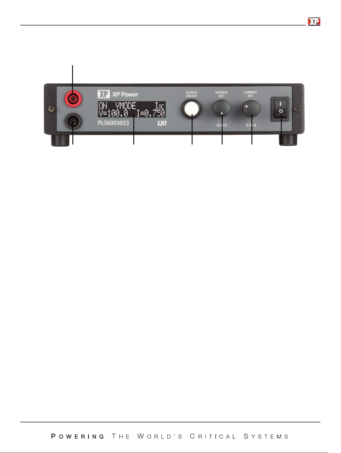
6. Front Panel
7
6
6.1 Front Panel
(1) Power Switch:
Please consult “Cautions Before Using” section before turning on power switch.
(2) Current Rotary Control:
Turn clockwise to increase current limit setting. Turning slowly will increment the least significant digit of the displayed
setting. As the control is turned faster more significant digits will be incremented. When the output is activated pressing
th
ontrol will display Set Current.
is c
5 4 3 2 1
(3) Voltage Rotary Control:
Turn clockwise to increase voltage limit setting. Turning slowly will increment the least significant digit of the displayed
setting. As the control is turned faster more significant digits will be incremented. When the output is activated
pressing this control will display Set Voltage.
(4) Output On/Off Button:
Pushing this button after
holding this button for more than 5 seconds and then releasing will put the power supply into Setup mode. See section
8.2 for setup instructions.
(5) Display:
16 character by 2 line display. This display shows set points, actual operating values, power supply operating status,
error messages, and setup informati
6) Negative Output Terminal
(
Black Standard Safety Banana Jack
(7) Positive Output Terminal
Red Standard Safety Banana Jack
ower to the power supply has been turned on enables the output voltage. Pressing and
the p
on.
9
Page 10
7. Operating Instructions
7.1 Normal Operation
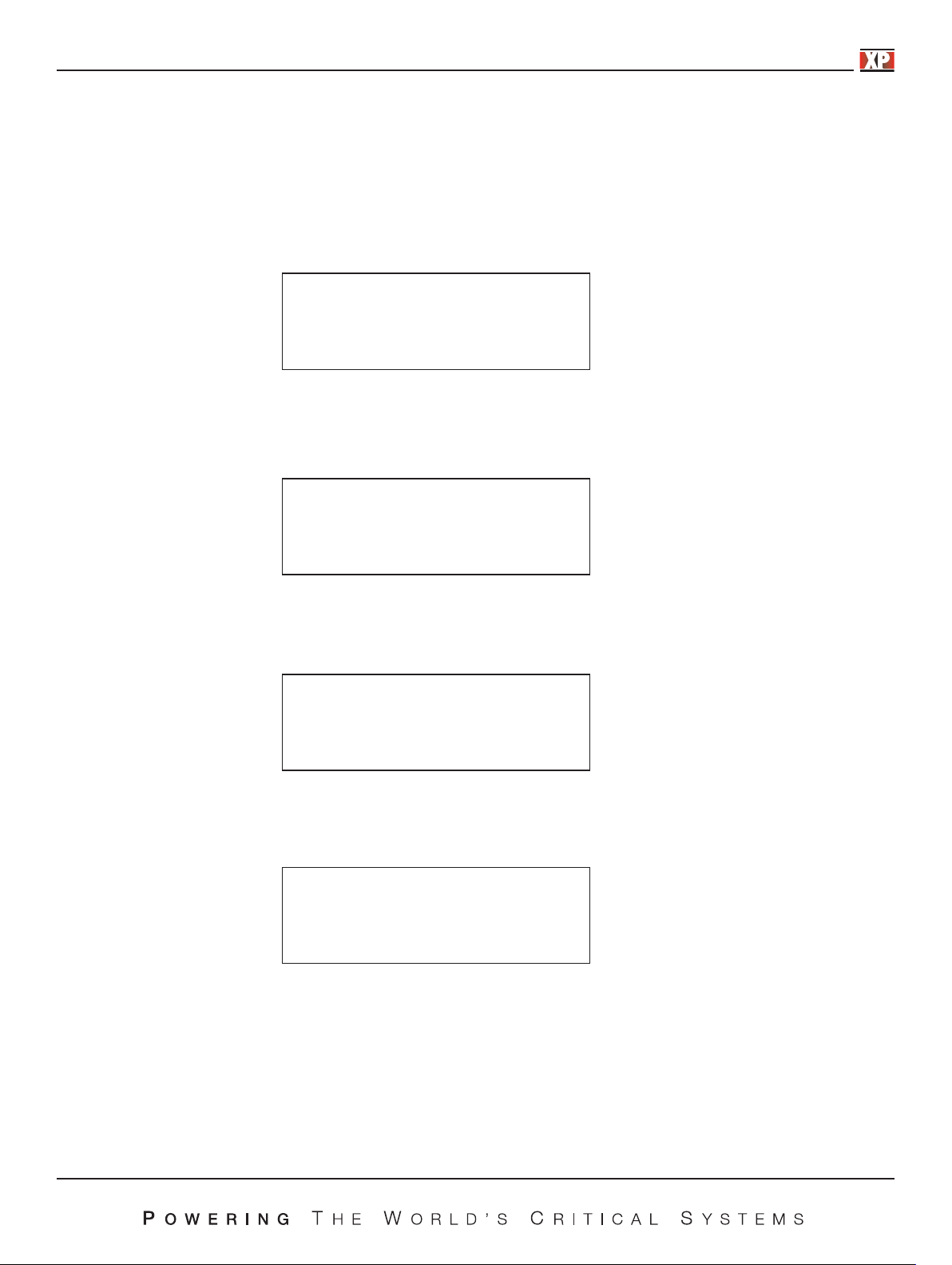
7.1.1 Power On
Connect the power input to the appropriate AC voltage source. Turn the Power Switch to the ON (I) position. On power up the
supply will execute a self-test. During the self-test the display will show the voltage and current capabilities of the supply and
the software revision.
PLS600
100 V 6 A V1.00
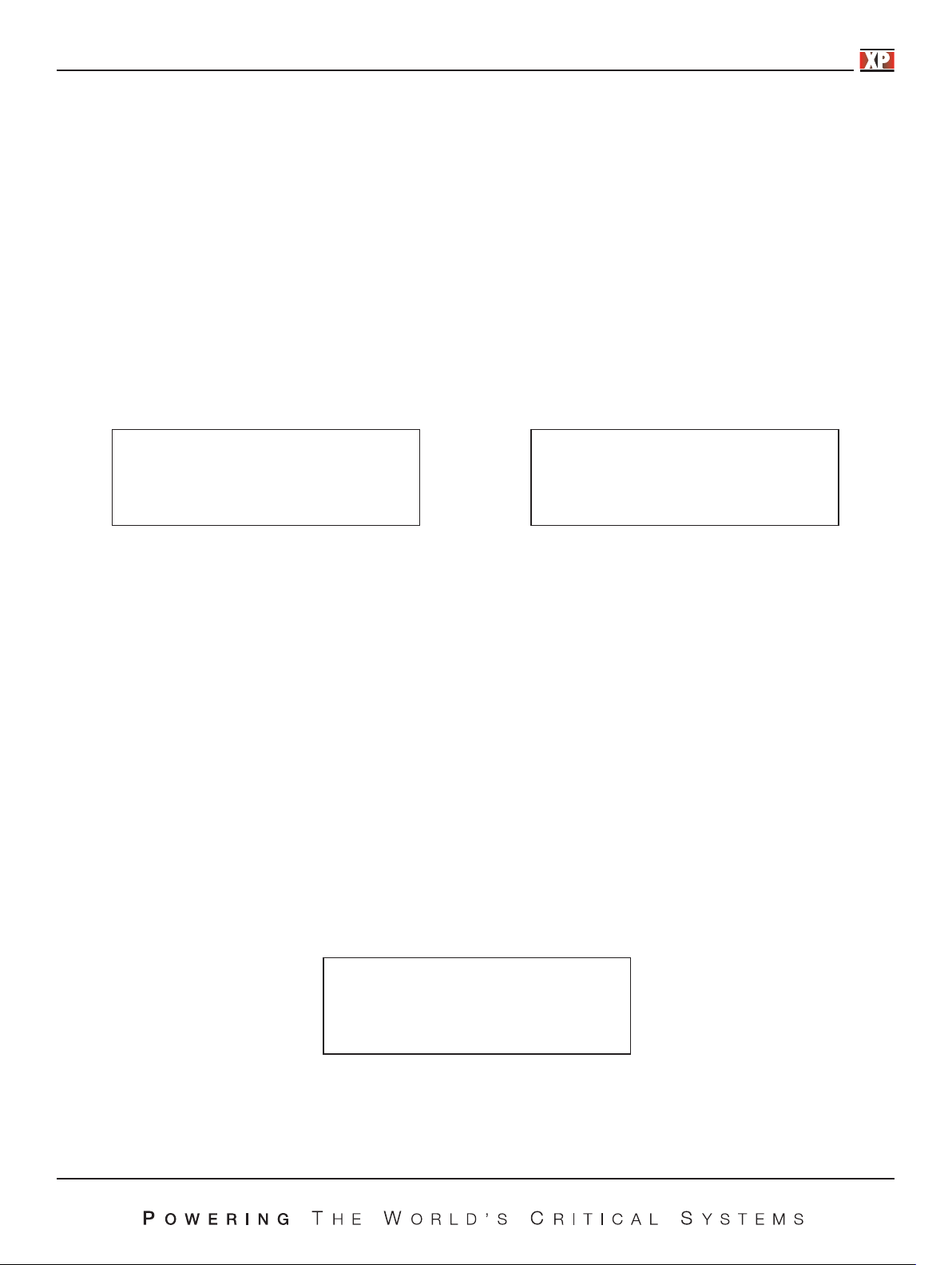
7.1.2 Enabling Output
After Power On the output of the power supply will be disabled until the output on/off button is pushed. The screen will display
the output status, the set points currently in force, and control mode (e.g., Local, Remote).
OFF Ioc
V=100.0 i=3.500
Until the output on/off button is pressed no power will be available on the output. When the output on/off button is pressed the
output will be turned on and the display will show the output status, the operating mode, and the actual output voltage and
current.).
on vmode Ioc
V=100.0 i=1.654
The power supply will always be in either voltage mode (VMODE) or in current mode (IMODE or PMODE). This state is
dependent on the power supply settings and the load. When in current mode the display will be as shown below.
on imode Ioc
V=88.2 i=3.500
To disable the output simply press the output on/off button again – this will remove all voltage from the output.
WARNING: Because the power supply has large output capacitors it can take up to 30 seconds for the internal circuit to fully
discharge the output after the output on/off button has been pressed to disable the output when there is no load.
Hazardous voltages may be present until the output i
s fully discharged.
It is possible to configure the power supply to turn the output on automatically when power is applied. See the Auto Start Setup
section (7.2.3) for further details on this option.
10
Page 11
7.1.3 Adjusting Voltage and Current
The voltage and current are set using the two controls labeled “VOLTAGE” and “CURRENT”. These controls use high quality
digital encoders rather than potentiometers. Turn the controls clockwise to increase a setting or counter clockwise to decrease
a setting. The encoders allow fine or coarse control of the voltage or current setting. The speed at which you turn
will determine the granularity of the setting. Turning at a slow rate will adjust the least significant digit of the parameter being
adjusted. Turning more rapidly allows coarse control to allow rapid changing of voltage or current.
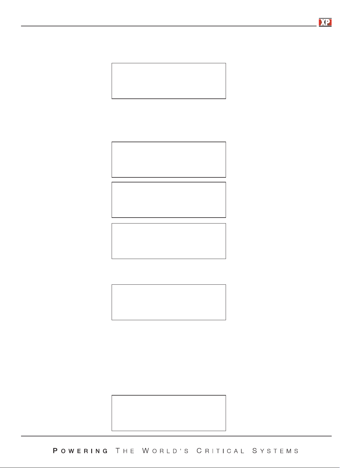
If the output is disabled while an adjustment is being made the voltage and current setting will be shown on the normal output
off display. The new se
If the output is on while an adjustment is being made the voltage or current will change in real time as the control is turned. A
special screen will be displayed during the adjustment as shown below. The screen will revert to the normal operating screen as
soon as the adjustment is complete. In the screens below the actual real-time o
bottom line and the set voltage or current is shown in the top line. In the cases below the power supply is current limiting as the
actual current matches the set current.
ttings w
ill take effect when the output on/off button is pressed.
utput voltage and current is shown on the
the controls
Vset v=100.0
V=88.2 i=3.500
Note that the actual voltage or current is load dependent and, therefore, may not match the displayed set point.
7.1.4 Displaying Set Points
At any time during operation, set points can be recalled by pressing the voltage or current rotary control. This action displays
the set points in the same manner as they would be displayed during a set point adjustment but without actually changing
anything. Pressing the voltage control displays the voltage set point and pressing the current control displays the current set
point.
7.1.5 Adjusting Over Voltage, Over Current and Over Power Protection.
The over voltage protection (OVP), over current protection (OCP) and over power protection (OPP) features limit the maximum
output current and voltage to avoid damages to the unit under test (UUT). OVP and OCP m
changed via the setup menus. OPP may only be changed in the setup menus. Note that Over Voltage and Over Current
protection can also be adjusted in the Setup menu – section 8.2.5.
If OVP, OCP, or OPP is set to maximum that protection will be disabled. Note: OVP, OCP, and OPP cannot be set to more than
10% over the maximum rating of the power supply.
iset i=3.122
V=88.2 i-3.122
ay be set as shown below or may be
To adjust OVP p
ress and release Voltage. The following screen will appear:
OVP set
OVP = 12.00
11
Page 12
Turn the Voltage control to adjust the OVP setting. When the desired setting is displayed press the output on/off button and the
supply will revert to its previous state.
To adjust OCP press and release the Current control. The following screen will appear:
OcP set
OcP = 2.500
Turn the Current control to adjust the OCP setting. When the desired setting is displayed press the output on/off button and the
supply will revert to its previous state.
If, during operation, any of these set points is exceeded the appropriate screen will be displayed as below.
Overvoltage trip
Enable to reset
Overcurrent trip
Enable to reset
Overpower trip
Enable to reset
Pressing Output On/Off when any of the trip screens are displayed will reset the trip and put the power supply back in idle
mode. The following screen will be displayed.
Off Ioc
V=100.0 i=3.500
Pressing Enable at this time will turn on the output.
7.2 Power Supply Setup
7.2.1 Introduction
Setup mode allows configuration of the power supply. Within setup one can adjust the power on state, select I/O options,
enable remote sense, and calibrate the power supply. To enter setup mode press and hold the output on/off button for at least 5
seconds. When enabled the initial setup screen will appear
12
System set up
mode
Page 13
Releasing the output on/off button will allow the user to scroll through the setup options by rotating either control.
System set up mode
System set up
Auto-start
System set up
Remote sense
System set up
POWER SETPOINT
System set up
Over limits set
System set up
LAN CONFIG
System set up
MSTER MODE
System set up
CALIBRATION
System set up
exit
13
Page 14

7.2.2 Mode
See Appendix A for analog control setup, Appendix B for USB control setup, and the PLS600 USB-Analog Programming Manual
for information on serial command syntax and on LXI usage.
7.2.2.1 USB/Analog
The Mode menu allows the user to choose between local control or remote control. If remote control is chosen the user can
further select if the control is to be analog voltage control or USB contro
these choices..
l. The Mode screen shown below is the entry point for
System set up
mode
Rotating either rotary control clockwise will show the following screens:
mode
local
Mode
remote
Mode
Analog voltage
Mode
Analog current
Mode
Analog dual
When the desired mode is displayed press the output on/off button to select it. If LOCAL or REMOTE is selected, no further
setup is required and the display will return to the setup main menu.
If REMOTE is selected the front panel will be locked out and control will be through the Ethernet port, USB port or analog i
exclusively.
14
nputs
Page 15
If ANALOG VOLTAGE is selected, the desired scaling of the analog voltage input must be selected and this screen will appear.
Analog full scale
v=10
Rotating the Voltage control will allow choice of 3V, 5V or 10V scaling. When the desired option is displayed, press the output
on/off button to select it. The display will return to the setup main menu.
Similarly, ANALOG CURRENT is selected, the desired scaling o
appear.
f the analog current input must be selected and this screen will
Analog full scale
I=10
Rotating the Current control will allow choice of 3V, 5V or 10V scaling. When the desired option is displayed, press the output
on/off button to select it. The display will return to the setup main menu.
Similarly, ANALOG DUAL is selected, the desired scaling of the analog voltage and current inputs must be selected and this
screen will appear.
Analog full scale
v=10 I=10
Rotating the Voltage control will allow choice of 3V, 5V or 10V scaling for the analog voltage port and rotating the Current control
will allow choice of 3V, 5V or 10V scaling for the analog current port. When the desired option is displayed, press the output
on/off button to select it. The display will return to the setup main menu.
System set up
mode
To change another setup item at this time you may
control until the following screen is displayed then press the output on/off button.
se either rotary control to select that option. To exit setup, rotate either
u
System set up
exit
15
Page 16

The following screen will be displayed.
Save config?
yes
Rotating either control will alternate between the screen above and the screen below.
Save config?
no
When the desired option is displayed press the output on/off button. Selecting YES will save any Setup changes to non-volatile
memory and they will be retained even when primary power is cycled. Selecting NO will not save Setup changes to n
memory and they will be in effect only until the unit is turned off.
The power supply will return to normal operating mode at this time.
7.2.3 Auto Start Setup
on-volatile
The Auto Start option, when enabled, causes the power supply to immediately provide output power when the power switch is
turned on without pressing the output on/off button. The voltage and current settings will be the same as they were when the
supply was last powered off.
WARNING: In Auto Start mode hazardous voltages may be present on the power supply output immediately after power is
applied.
When in setup mode rotate either rotary control until the AUTO-START screen is displayed then press the output on/off button.
The following screen will be displayed.
Auto-start?
yes
Rotating either control will cycle between the yes and no option.
Auto-start?
no
16
Page 17

When the desired yes or no option is displayed press the output on/off button to select it. After selection the following screen
will be displayed:
System set up
Auto-start
To change another setup item at this time you may use either rotary control to select that option. To exit setup, rotate either
control until the following screen is displayed then press the output on/off button.
System set up
exit
The following screen will be displayed.
Save config?
yes
Rotating either control will alternate between the screen above and the screen below.
Save config?
no
When the desired option is displayed press the output on/off button. Selecting YES will save any Setup changes to non-volatile
memory and they will be retained even when primary power is cycled. Selecting NO will not save Setup changes to non-volatile
memory and they will be in effect only until the unit i
The power supply will return to normal operating mode at this time.
7.2.4 Remote Sense Setup
Most power supplies with remote sense require a second set of wires between the power supply and the load to sense the
voltage at the load. The PLS600 supply uses proprietary technology to digitally compensate for these resistances without the
extra sensing wires. Prior to using the Remote Sense o
how to enable Remote Sense and how to do the calibration required. Once in setup mode rotate either control until the REMOTE
SENSE screen is displayed then press the output on/off button. The following screen will be displayed.
s turned off.
ption a simple load calibration must be performed. This section will detail
Remote Sense
ON
17
Page 18
Rotating either control will alternate between the ON or OFF selection. Press the Output On/Off button when the desired mode
is displayed.
Remote Sense
OFF
If the NO option is selected the system will revert to the Setup main menu. If the YES option is selected the following screen will
be displayed:
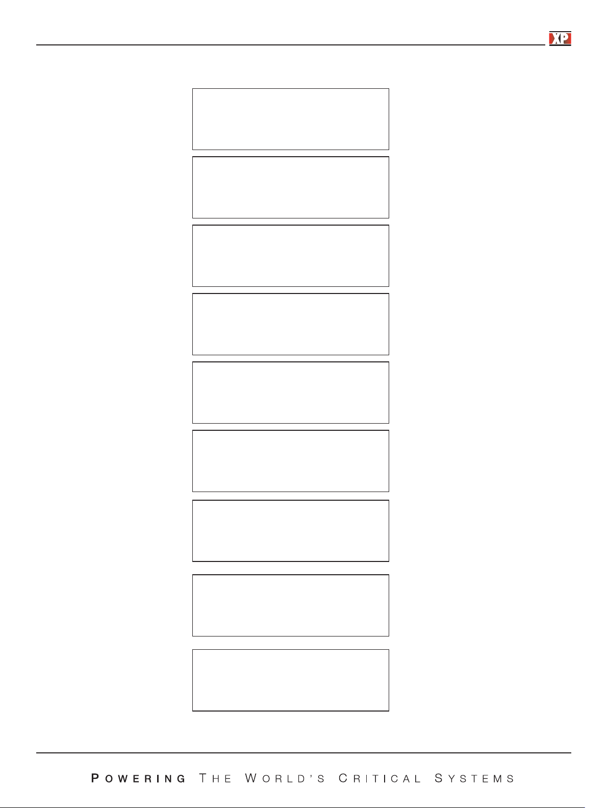
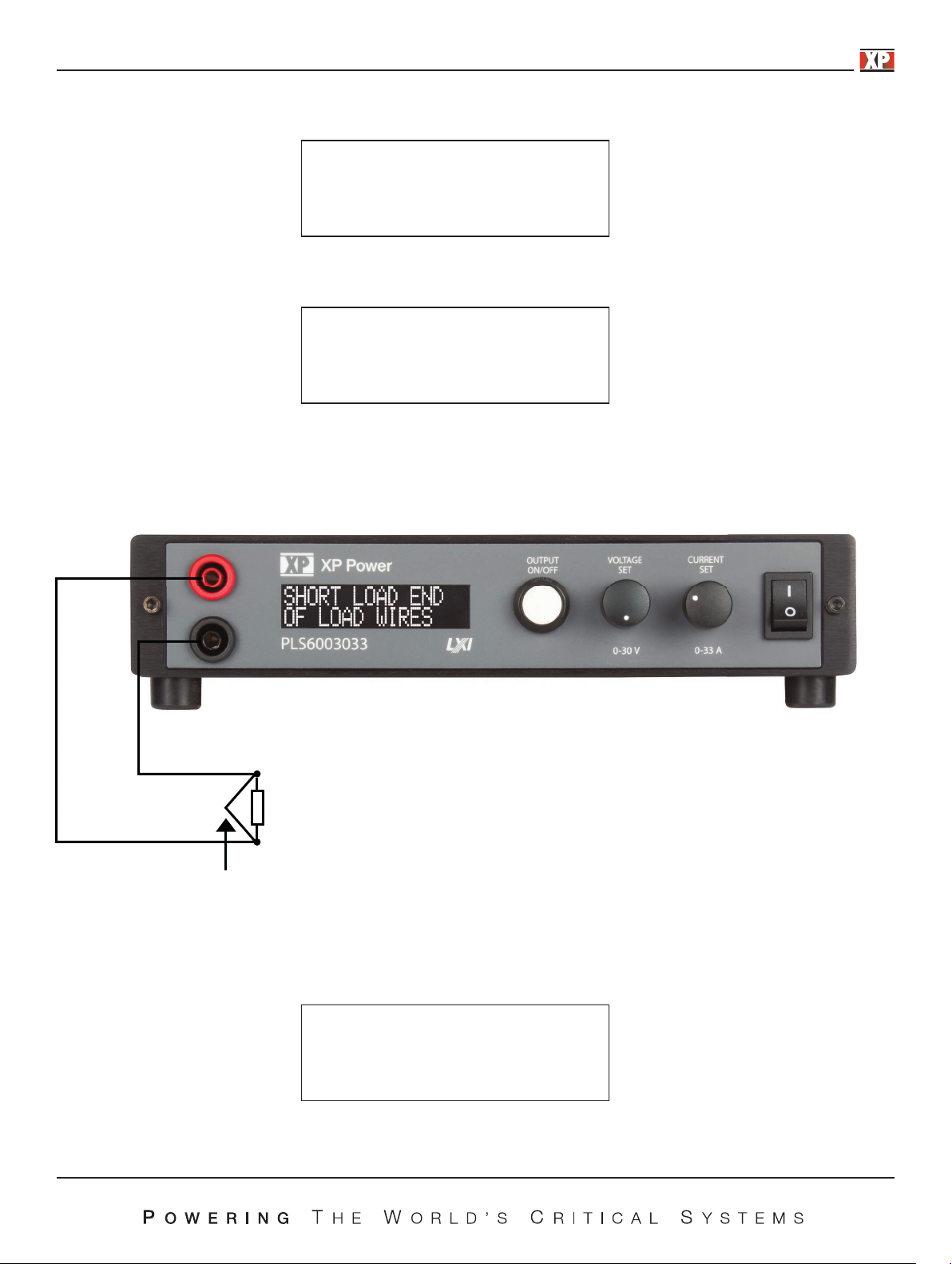
Short load end
of load wires
At this point the load end of the wires must be shorted as shown below:
Load
Short here
It is important that a good short with heavy wire is made as failure to do this will result in a poor remote sense calibration.
Once the short is in place, p
ress the output on/off button. The following screen is an example of what will be displayed.
Adjust to Normal
current I=2.33
18
Page 19

Now set the current to at least as much as you would expect your load to consume. More is better if your load wires are
capable of handling the current. When ready press the out
The power supply will now measure the output current and the total voltage drop in the load wires and use these values to
calculate the resistance of the load wires. As long as Remote Sense remains enabled the power supply will use this resistance
value to calculate output voltage based on output current. It will then adjust the output voltage at the power terminals in real
time
If, during the remote sense setup, the lead resistance is so much that remote sense will not be able to operate reliable the
following error screen will be displayed.
orrect for the drop in the load cables.
to c
put o
n/off button.
Load resistance
too great
The error screen will be followed by:
Remote sense
retry
Pressing the Output On/Off button at this time will bring the user back to the Remote Sense On screen. Remote sense must be
turned off or the load wires must be improved to allow calibration of remote sense.
If the remote sense calibration completed normally the display will return to the REMOTE SENSE COMPLETE screen.
Remote sense
Complete 99MΩ
Pressing Output On/Off button will now return the system to the following screen:
System set up
Remote sense
To change another setup item at this time you may use either control to select that option. To exit setup, rotate either control
until the following screen is displayed then press the output on/off button.
System set up
exit
19
Page 20

The following screen will be displayed.
Save config?
yes
Rotating either control will alternate between the screen above and the screen below.
Save config?
no
When the desired option is displayed press the output on/off button. Selecting YES will save any Setup changes to non-volatile
memory and they will be retained even when primary power is cycled. Selecting NO will not save Setup changes to non-volatile
memory and they will be in effect only until the
The power supply will return to normal operating mode at this time.
7.2.5 Power Limit Setup
nit is turned off.
u
The PLS600 power supply is designed to supply up to 600 watts of output power to a load. In some applications it may be
desirable to limit the maximum power to something lower than the maximum available from the power supply. This section
describes how to set up power limiting.
m
1) Enter setup
2) Rotate the voltage or current control until the following screen appears.
ode
System set up
Power setpoint
3) Push the output on/off button and the following screen will appear.
Power setpoint
P = 606w
4) Rotate the voltage or current control to adjust the maximum power that can be delivered by the supply. This may be in
the range of 1% to 101% of the maximum rating (6 watts to 606 watts for the PLS600).
5) When the power is set to the maximum desired
6) Now rotate either control until the following screen is displayed then press the output on/off button.
s displayed then press the output on/off button.
power i
20
System set up
exit
Page 21

7) The following screen will be displayed.
Save config?
yes
Rotating either control will alternate between the screen above and the screen below.
Save config?
no
When the desired option is displayed press the output on/off button. Selecting YES will save any Setup c
memory and they will be retained even when primary power is cycled. Selecting NO will not save Setup changes to non-volatile
memory and they will be in effect only until the unit is turned off.
The power supply will return to normal operating mode at this time and if you selected Save Config, Yes then the new power
limit will be in effect. To remove the power limit the sa
7.2.6 Over Limits
Over Limits allows the user to set in maximum values for voltage, current, and power that are less than the full power supply
rating in cases where there is a desire to protect the load. Note that Overvoltage and Overcurrent protection can be set from the
front panel as shown in section 8.1.5. To enter Over Limits setup press Enable when the following screen is displayed within the
Setup menu.
rocedure should be used and the power should be set to 606 watts.
me p
hanges to non-volatile
System set up
Over limits set
When Output On/Off button is pressed the following screen will appear.
OVP set
OvP=12.00
This screen allows the adjustment of the Over Voltage trip point. Turn either the voltage or the current control to adjust the
value. Press the output on/off button when the value you wish is displayed. When the output on/off button is pressed the
following screen will be displayed:
OcP set
OcP = 2.500
21
Page 22

This screen allows the adjustment of the Over Current trip point. Turn either the voltage or the current control to adjust the
value. Press the output on/off button when the value you wish is displayed. When the output on/off button is pressed the
following screen will be displayed:
OpP set
OpP = 660
This screen allows the adjustment of the Over Power trip point. Turn either the voltage or the current control to adjust the value.
Press the output on/off button when the value you wish is displayed. When the output on/off button is pressed the following
screen will be displayed:
System set up
Over limits set
To change another setup item at this time you may use either rotary control to select that option. To exit setup, rotate either
control until the following screen is displayed then press the output on/off button.
System set up
exit
The following screen will be displayed.
Save config?
yes
Rotating either control will alternate between the screen above and the screen below.
Save config?
no
When the desired option is displayed press the output on/off button. Selecting YES will save any Setup changes to non-volatile
memory and they will be retained even when primary power is cycled. Selecting NO will not save Setup changes to non-volatile
memory and t
hey w
ill be in effect only until the unit is turned off.
The power supply will return to normal operating mode at this time.
22
Page 23

7.2.7 LAN setup
The PLS600 series of power supplies comes with an Ethernet LAN interface. While in local mode and setup mode the power
supply LAN setup data may be viewed. Normally the power supply mode will be used in DHCP mode and an IP address will be
provided by the router the supply is connected to. To view the current setup do the following.
1) In setup mode turn a control until the following screen appears.
System set up
Lan config
2) Press Output On/Off button and the following screen will be displayed.
Lan settings
connected
The above screen will be displayed if the supply is connected to a LAN if the supply is not connect to a LAN the lower line will
read NOT CONNECTED.
3) Rotate a control one click and the following screen will be displayed. Note that the IP address displayed will be the one
assigned by your router and will not match the address shown below.
Lan ip address:
10.45.45.84
4) Rotating the control another click will display the MAC address for this supply. This address will not match the one in the
example below as every supply has its own unchangeable MAC address.
Lan mac address:
001EC095E517
5) Rotating the control one step further will display the following screen.
Reset lan config
If you wish to reset the LAN settings to the factory default press the output on/off button again. Now rotate either control until
the following screen your selection of Yes or No is displayed. Pressing Output On/Off button once again while Yes is displayed
will reset the power supply LAN settings.
This feature is useful if the IP address has been set to a static address and is no longer able to communicate with the LAN.
For further information on use and control of the power supply with Ethernet LAN see Appendix C.
23
Page 24

7.2.8 Series and parallel operation
The PLS600 series of power supplies may be used in series or parallel combinations.
For both of these modes the power supplies used must be identical models.
No more than two power supplies may be put in series due to voltage isolation and safety considerations.
c
WARNING: Output terminal isolation: No output terminal may be more than 600VDC from other terminal or
For parallel operation up to 4 units may be connected in MASTER/SLAVE mode
In order to parallel or series PLS600 power supplies one power supply must be set up to be the master and the rest of the
power supplies must be set up as slaves. To put a power supply in master mode take the following steps:
1) Enter setup mode.
hassis ground.
SYSTEM SETUP
MODE
2) Rotate the voltage or current control until Master Mode screen appears.
SYSTEM SETUP
MASTER MODE
3) Press the output on/off button then rotate the voltage or current control to select parallel or series master mode. Press the
output on/off button when the mode you wish is displayed.
Master mode
Parallel (i)
Master mode
Series (v)
4) Rotate the voltage or current control until the Exit screen is displayed
System set up
exit
5) Press Output On/Off button and the following screen will be displayed.
Save config?
yes
24
Page 25

6) Press the output on/off button again to save the configuration and leave the power supply in master mode
Next, the other power supplies must be put in slave mode to allow them to follow the output of the master supply.
For parallel supplies take the following steps:
1) On all of the slave supplies set the voltage to the maximum voltage that will be desired in the application. Not
voltage setting on the slaves will not be the actual voltage output. The actual voltage output will be determined by the master.
This setting will only determine the maximum voltage that will be output by the slave when following the master. All slaves
should be set to this same maximum voltage.
2) Put the power supply in analog current control mode by taking the following steps:
a. Put the p
ower supply is setup mode
e that this
System set up
mode
b. When MODE is displayed press the output on/off button then rotate the voltage or current control until the following screen is
displayed.
Mode
Analog current
c. Press the output on/off button
Analog full sclae
1=10
d. Press the output on/off button again to choose full scale as a 10 volt input.
e. Rotate the voltage or current control until the Exit screen is displayed.
System set up
exit
f. Press the output on/off button
Save config?
yes
g. Press Output On/Off button again to save the configuration and leave the power supply in analog control mode.
25
Page 26
3) Connect the power supplies together.
a. On the analog connector in the back of the unit connect all pins 2 together to tie the analog grounds together.
b. Also on the analog connector in the back of the unit connect pin 5 (Sharing Output) of the master supply to pins 3 (Voltage
Control Input) of the slave supply.
c. Now connect the all the positive outputs together and all the negative outputs to
Yo
u have now completed setup for parallel operation of the power supplies. When connected to a load, voltage and current will
be determined by the master supply. Adjusting the voltage on the master will adjust the outputs on all of the supplies. As the
load changes, the current will be shared between all of the supplies. Note that the current setting on the master will reflect the
actual c
For series supplies take the following steps:
1) On the slave supply set the current to the maximum current that will be desired in the application. Note that this voltage
setting on the slave will not be the actual current output. The actual current output will be determined by the master. This
setting will only determine the maximum current that will be output by the slave when following the master.
2) Put the power supply in analog current control mode by doing the following:
a. Put the power supply is setup mode
nt output by the paralleled supplies divided by the number of supplies in parallel.
urre
gether.
System set up
mode
b. When MODE is displayed press the output on/off button then rotate the voltage or current control until the following screen is
displayed.
Mode
Analog voltage
c. Press the output on/off button
Analog full scale
I=10
d. Press the output on/off button again to choose full scale as a 10 volt input.
e. Rotate the voltage or current control until the Exit screen is displayed.
System set up
exit
26
Page 27
f. Press the output on/off button
Save config?
yes
g. Press output on/off button again to save the configuration and leave the power supply in analog control mode.
3) Connect the power supplies together.
a. On the analog connector in the back of the unit connect all pins 2 together to tie the analog grounds together.
b. Also on the analog connector in the back of the unit connect pin 5 (Sharing Output) of the master supply to pins 4 (Curre
Control Input) of the slave supplies.
c. Now connect the all the positive outputs the master to the negative output of the slave. The positive output of the slave and
the negative output of the master should be connected to the load.
You have now completed setup for series operation of the power supplies. When connected to a load, voltage and current will
be determined by the master supply. A
load changes the voltage will be shared between the supplies. Note that the voltage setting on the master will reflect the actual
voltage output by the series supplies divided by two.
7.2.9 Calibration
djusting the voltage on the master will adjust the outputs on the slave supply. As the
nt
Power supply calibration allows qualified personnel to calibrate the output voltage and current and the displayed v
current. The process is very simple but it does require some specialized equipment. The required equipment is a calibrated volt
meter and a calibrated current shunt. The current shunt must be rated for at least the full rated output current of the power
supply but must not be rated at so high a current that a meaningful reading cannot be obtained at the full rated current of the
power
supply.
To
calibrate the power supply use the following procedure:
Enter setup mode. Once in setup mode rotate either rotary control until the CALIBRATE screen is displayed then press the
output on/off button. The following screen will be displayed.
oltage and
Calibrate?
yes
Rotating either control will alternate between the ON or OFF selection. Press the output on/off button when the desired mode is
displayed.
Calibrate?
no
27
Page 28

If the NO option is selected the system will revert to the Setup main menu. If the YES option is selected the following screen will
be displayed:
Output
Open load
At this point only a volt meter should be connected to the output. No load should be connected. See illustration below.
When the volt meter is connected, press the output on/off button. The following screen is an example of what will appear.
Set voltage to
10.0 volts
28
Page 29
Now, using the Voltage control, adjust the output until the external volt meter reads exactly the voltage displayed on the power
supply display. Note that the voltage displayed on the screen will vary depending on the power supply model.
When the two voltages match exactly, press the output on/off button and the following screen will appear:
Set voltage to
100.0 volts
Again, using the Voltage control, adjust the output until the external volt meter reads exactly the voltage displayed on the power
supply display. Note that the voltage displayed on the screen will vary depending on the power supply model.
When the two voltages match exactly, press the output on/off button and the following screen will appear:
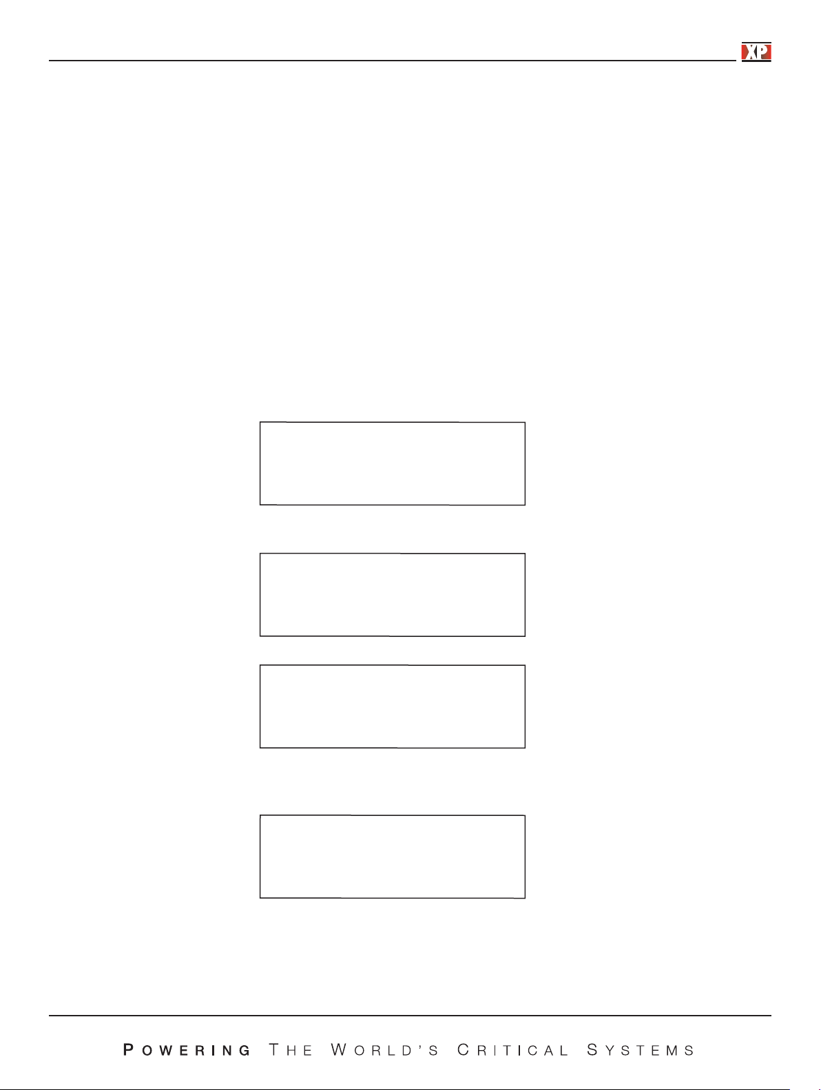
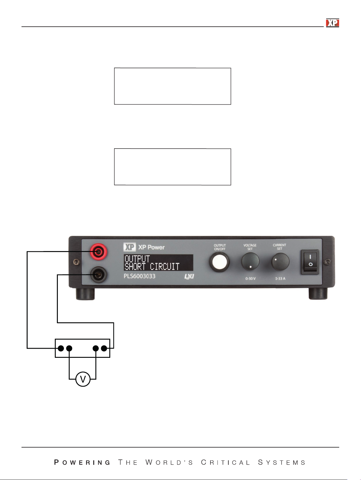
Output
Short circuit
Now a current shunt must be connected a
guidance.
Current Shunt
cross the output and a voltage meter connected to the shunt. Use the figure below for
29
Page 30
When the power supply is configured as in the figure on previous page, press the output on/off button. The following screen will
now appear:
Set current to
0.600 amps
Using the Current control, adjust the output until the external volt meter reads exactly the current displayed on the power supply
display. Note that the voltage displayed on the meter will be dependent on the type of current shunt used. The voltage to be
ad
justed t
current. The resistance is, therefore, R=.050/10=0.005 ohms. So, for the calibration screen shown above the voltage meter
should read V=0.600*0.005=.003 volts.
Note also that the current displayed on the screen will vary depending on the power supply model.
o obtain the correct current must be calculated. For example, a 10 amp, 50mV shunt will drop 50mV with 10 amps of
When the current is exactly c
orrect, press the output on/off button and the following screen will appear:
Set current to
6.00 amps
Using the same formula as above, the voltage reading on the volt meter should be 0.030 volts (for this example) when the supply
is set correctly.
When the current is exactly correct, press the output on/off button and the following screen will appear:
Calibration
complete
Pressing Output On/Off button at this point will return you to the Setup main menu.
System set up
calibrate
To change another setup item at this time you may use either rotary control to select that option. To exit setup, rotate either
control until the following screen is displayed then press the output on/off button.
System set up
exit
30
Page 31
The following screen will be displayed.
Save config?
yes
Rotating either control will alternate between the screen above and the screen below.
Save config?
no
When the desired option is displayed press the output on/off button. Selecting YES will save any Setup changes to non-volatile
memory and they will be retained even when primary power is cycled. Selecting NO will not save Setup changes to non-volatile
memory and they will be in effect only until the u
The power supply will return to normal operating mode at this time.
s turned off.
nit i
31
Page 32

Appendix A - Analog Control Inputs
As a standard feature, PLS600 power supplies have an analog port that allows remote control. The analog control option allows
the use of either 0 - 3 volt inputs, 0 - 5 volt inputs or 0 -10 volt inputs. In addition, there is a 3.0 volt reference source so that
external potentiometers can be used as inputs.
The pinout of the Analog control connector is as follows:
Pin Function
1 3.0 Volt Reference
2 Ground
3 Voltage Control Input
4 Current Control Input
5 Sharing Output
The connector physical pinout is shown below. The correct mating connector is an On Shore Technology Inc. 5 pin connector
such as their part number OSTTJ0531530.
To use a potentiometer as the control source connect one end of the potentiometer to the 3.0 Volt Reference, the other end to
Ground and the wiper to the control Input. The potentiometer should be in the range of 1K to 10K ohms. Set the power supply
to run from a 3 volt analog input on voltage or current or both.
CAUTION: Noise on the inputs can affect the performance of the power supply. For long l
the wires together and consider shielding.
eads the user should tightly twist
32
Page 33

Appendix B - USB Control Input
USB drivers are available on the XP Power website at https://xppower.com
Be sure to download and extract the PLS600 USB driver to your local drive. The extraction location wiill be required in later steps.
The standard USB input is a USB 2.0 full speed compatible USB port.
To install the USB drivers, make sure the unit is powered on the PLS600 unit is connected to the computer’s
Open Device Manager and locate the PLS600 SUPPLY under other devices.
USB port.
Right click on the PLS600 SUPPLY and select properties. On the driver tab, select Update Driver:
33
Page 34

Click Browse to locate where the PLS600 supply USB drive was extracted to and click next.
Once the driver has been successfully installed, windows will verify the installation and the PLS600 Supply can now be accessed
through the USB communication.
34
Page 35

Appendix C - Communication Over Lan
You can communicate with your PLS600 power supply over the LAN connection using a Web server, or using the built in SCPI
command set over UDP/IP. These methods are a convenient way to communicate with the power system without using I/O
libraries or drivers. In all cases, you must first establish a LAN connection from your computer to the power system as in section
0
.
sing the Web Server
U
Your power system has a built-in Web server that lets you control it directly from an internet browser on your computer. With the
Web server, you can access the front panel control functions including the LAN configuration parameters. Up to two
simultaneous connections are allowed. With additional connections, performance will be reduced.
NOTE
The built-in Web server only opera
The Web server is enabled when shipped. To launch the Web server:
1) Open the internet browser on your computer.
2) Obtain the power supplies IP address as described in section 8.2.7. Enter the instrument’s IP address into the browser’s
Address field to launch the Web server.
3) You will be asked for a user name and p
4) The following home page will appear:
ver the LAN interface. It requires Internet Explorer 7+ or Firefox2+, or Chrome.
tes o
assword. The default user name is “admin” and the default password is “password”.
35
Page 36

5) Click on the PLS600 Control button to begin controlling your power supply.
If desired, you can control access to the Web server using password protection. As shipped from the factory, the password is
“password”. To change the password, click on the LAN Settings button.
The power supply is shipped from the factory in DHCP mode so that it will automatically obtain a password from your router.
Should you wish to set a static IP address you may do so from the LAN Settings page.
As shipped from the factory you may monitor your power supply using the LAN interface but not control it. In addition, a user
may also adjust the power supply settings from the front panel. Should the user wish to control the power supply and lock out
the front panel the power supply should be put into remote mode as described b
1) Enter setup mode and the push the output on/off button on the following screen.
elow.
System set up
mode
2) When the following screen is displayed rotate either rotary control to select REMOTE
Mode
Local
Mode
remote
3) When REMOTE is displayed press the output on/off button. Note that when in remote mode all menu selections other than
REMOTE or LOCAL are suppressed.
4) Exit and Save the setting.
Controlling your power supply using TCP/IP or UDP/IP
Your power system has built-in TCP/IP and UDP/IP interfaces that allow you t
SCPI command set.
To use either interface use the IP address as set up in previous chapters of this manual and use port 8003 for TCP and 8005 for
UDP. Follow each SCPI command with a line feed. A complete description of the SCPI command set is in the supplied
Programming Manual.
o control the power supply using the full supported
36
Page 37

Appendix D - Rack Mount Option
Installation of the rack mount kit is a simple procedure but damage to the power supply can occur if it is not done properly.
Please follow the steps carefully.
1) Unplug the power supply.
2) Remove the rubber feet as shown in the figure below.
Retain the feet and screws in case they are needed later.
CAUTION: If the feet are replaced with the incorrect screws damage to the power supply can occur. Be sure to use 6-32
screws with ¼ inch length.
37
Page 38

3) Remove the screws from the front panel as shown in the figure below.
CAUTION: When the screws are removed from the front panel the panel will be loose. Do not let the panel fall away from the
power supply as the interconnect cables may come loose or be damaged. Hold the panel up against the power supply at all
times.
4) Hold the rack mount plate in front of the power
supply front panel and secure with the new screws
provided with the rack mount plate. Do not use
the original screws as they will be too short.
See figure right:
5) If a second power supply is to be mounted on the rack mount kit begin with Step 2 above. If a blank panel is to be mounted
in place of a second power supply use provided panel and screws. See figure below.
38
Page 39

Appendix E - Error Messages
This appendix describes the various error conditions that can occur in the power supply. There are two groups of error
conditions; first, errors that involve exceeding of limits set by the operator or that are hard programmed into the unit, second,
errors involving a failure within the power supply.
The first group of errors – errors caused by limits set by the user or the f
actory are described below:
Overcurrent trip
Enable to reset
The “OVERCURRENT TRIP” error is caused by exceeding the current set by the “OCP SET” command. If the current limit value
is set to below the “OCP SET” value this condition will rarely if ever occur. If the “OCP SET” value is below the current limit
value then this condition will occur whenever the load resistance is low enough to allow the set value to be exceeded without
going into voltage. To re
set the power supply simply press the Output On/Off button.
Overvoltage trip
Enable to reset
The “OVERVOLTAGE TRIP” error is caused by exceeding the voltage set by the “OVP SET” command. If the voltage limit value
is set to below the “OVP SET” value this condition will rarely if ever occur. If the “OVP SET” value is below the voltage limit
value then this condition will occur whenever the load resistance is high enough to allow the set value to be exceeded without
going into current limit.
reset the power supply simply press the Output On/Off button.
To
Overpower trip
Enable to reset
The “OVERPOWER TRIP” error is caused by exceeding the power set by the “OPP SET” command. To reset the power supply
simply press the Output On/Off button.
Temperature err
Enable to reset
The “OVER TEMPERATURE” error is caused by exceeding the maximum operating temperature of the power supply. To reset
the power supply simply press the ENABLE button. If the power supply is within its temperature limits when the Output On/Off
button is pressed the supply will return to normal operation. If the supply is still outside its operating limits the error will persist.
If this error reoccurs
fter a cool down period check to be sure that there is at least one inch of clearance around all the vents.
a
39
Page 40

The second group of errors – errors involving a failure within the power supply are described below:
Output error
Enable to reset
The “PWM ACTIVATE ERR” error is an internal error of the power supply. This is usually caused by a component failure. To
reset the power supply simply press the Output On/Off button. If the error reoccurs the power supply must be repaired by the
factory.
12v bias err
Enable to reset
The “12V BIAS ERR” error is an internal error of the power supply. This is usually caused by a component failure. To reset the
power supply simply press the Output On/Off button. If the error reoccurs the power supply must be repaired by the factory.
3.3v bias err
Enable to reset
The “3.3V BIAS ERR” error is an internal error of the power supply. This is usually caused by a component failure. To reset the
power supply simply press the Output On/Off button. If the error reoccurs the power supply must be repaired by the factory.
Pfc failure
Enable to reset
The “PFC FAILURE” error is an internal error of the power supply. This is usually caused by a component failure. To reset the
power supply simply press the Output On/Off button. If the error reoccurs the power supply must be repaired by the factory.
Hs temp error
Enable to reset
The “HS TEMP ERROR” error indicates an overtemperature of the main heatsink. This is usually caused an ambient temperature
over 40C. To reset the power supply simply press the Output On/Off button. If the error reoccurs and the ambient temperature
is within specifications the power supply must be repaired by the factory.
40
Page 41

Fan stall error
Enable to reset
On power up the power supply runs a check on several internal systems to make sure all is working well prior to power up. The
“SELF-TEST ERROR” error is an internal error of the power supply that can occur during initial power on when the self-test is
performed. The unit must be sent in to the factory for repair.
COMM TIMEOUT
Enable to reset
“COMM TIMOUT” indicates that one of the power supplies communication ports has not responded in a timely manner. To
reset the power supply simply press the Output On/Off button.
41
Page 42

Service Information
A Return Material Authorization (RMA) number must be obtained from XP Power before a power supply may be returned for
repair.
When requesting an RMA please provide the following information:
Model number
Serial number
A description of the problem including the error indication if available
If possible, return the unit in its original packaging. Do not return the power cord or U
with the unit being returned. Units must be well packaged when shipping to XP Power; the repair of any damage incurred during
shipping is not covered by warranty and will be charged to the customer.
Return all units to XP Power using pre-paid shipping.
For warranty repairs, XP Power covers the cost for return shipment to the customers. For out-of-warranty re
XP Power Customer Support.
tick. Please include the RMA number
SB s
pairs please contact
42
Page 43

Limited Three Year Warranty
XP Power warrants to the original purchaser that its products and the component parts will be free from defects in workmanship
and materials for a period of three years from date of purchase. XP Power will, without charge, repair or replace, at its option,
defective product or component parts.
This warranty does not apply in the event that:
• The product is damaged by misuse, a
• The product is opened, modified, disassembled or repaired without consent.
• The serial number is altered, defaced or removed.
• The product is found to have no defects, in which case a re-inspection and handling charge will be applied.
This warranty is in lieu of all other warranties, obligations, and liabilities, either expressed or implied, and are the purchaser
xclusive remedy. XP Power makes no warranty, either expressed or implied, of merchantability, fitness for a particular purpose
e
or otherwise. In no event shall XP Power be liable whether in contract, tort or negligence, for special, indirect, incidental or
consequential damages of any kind, including the loss of business or profits, or any other losses incurred by purchaser or any
third party, th
price.
XP Power reserves the right to make changes or improvements to its products without any obligation to upgrade previously
manufactured products.
e C
ustomer’s remedies being limited, at XP Power’s option, to replacement, repair or credit at the original purchase
ccident, abuse or alterations.
’s
43
 Loading...