


ENGLISH
USER MANUAL
OPTIMA-33 10K / 20K / 30K
3 Phases IN - 3 Phases Out
ONLINE-DOUBLE CONVERSION UPS 400/230V & 208/120V
Technical information on this manual is property of XMART . This manual Information cannot be copied or distributed totally or partially without written approval of XMART.
XMART can introduce modifications in their products or manuals without further notice. .
XMART is not responsible of mistakes or missing information in this manual.
XMART is not responsible for wrong use a third part can do of this information.
Trademarks and logos in this manual are property of their owners.
Xmart Optima-33 10K / 20K

USER MANUAL - OPTIMA-33 10K / 20K / 30K
TABLE OF CONTENTS
1.SAFETY
2.AVAILABLE MODELS
3.- UPS INSTALLATION: SITE PLANING
SITE INSPECTION & INSTALLATION CONDITIONS
TOWER UPS INSTALLATION
EXTERNAL CIRCUIT BREAKERS & WIRING SELECTION
4.- UPS INSTALLATION: SINGLE UPS - TERMINAL BLOCK
UPS AC LINES CONFIGURATION
AC TERMINAL BLOCKS
EXTERNAL BATTERY CONNECTION
5.- UPS INSTALLATION: PARALLEL UPS - TERMINAL BLOCK
GENERAL COMMENTS
UPS AC LINES CONNECTION
PARALLEL CONTROL CABLES CONNECTION
6.- START-UP: SINGLE UPS
INSPECTION BEFORE START-UP
SINGLE UPS - START UP PROCEDURE
7.- START-UP: PARALLEL UPS
REQUIREMENTS FOR PARALLEL UPS SYSTEMS
INSPECTION BEFORE START-UP
PARALLL UPS - START UP PROCEDURE
8.- OPERATION INTERFACE
FRONT PÀNEL: PUSH BUTTONS / LEDS / LCD
9.- OPERATION: SINGLE UPS
10.- OPERATION: PARALLEL UPS
REMOVING UPS FROM PARALLEL SYSTEM
ADDING UPS TO PARALLEL SYSTEM
11.- UPS CONFIGUIRATION
12.- ERROR CODES, ALARMS & TROUBLESHOOTING
13.- TECHNICAL SPECIFICATIONS
14.- LIMITED WARRANTY
www.xmart-ups.com |
130612-OPTIMA-33 10K/20K (ENGLISH) - 0 |
USER MANUAL - OPTIMA-33 10K / 20K / 30K
1. GENERAL SAFETY INSTRUCTIONS
WARNING: It is required to read and understand this manual. Follow all instructions given in this manual for starting up and operating this product. Only qualified technician must start-up, operate and maintain this product. Keep manuals as a guide for future consults.
WARNING: This product operates with dangerous voltages. It must be installed, operated and maintained ONLY by qualified technicians trained for this kind of products. Service personnel MUST know and understand very well all electric risks related to this product. UPS manufacturer or distributor will never be responsible for any accident produced by lack of knowledge or negligent practices at the moment of install, starting up or maintain this product.
UPS manufacturer or distributor is not liable for any damage that might rise from misusing this unit or defective installation. WARNING: If you are not qualified technician do not try to install, operate or repair this product.
WARNING: Do not try to install, operate or repair this product if you are not accompanied by another qualified person able to offer first aid support in case of emergency or accidents.
WARNING: Internal area of this product is locked by screws. Do not try to access inside the UPS unless you are a qualified technician. UPS must be checked, repaired and maintained by qualified personnel only.
CAUTION!!: ELECTRIC SHOCK RISK
CAUTION: There are dangerous voltages in the UPS power outlets although the equipment is not plugged to power line. CAUTION: Inside this equipment, due to internal batteries, there are ALWAYS dangerous voltages, thought the UPS is OFF and unplugged of power line.
CAUTION: There are dangerous voltages in DC (Direct Current) Capacitors. Please Check Capacitor location in Figure 8.4.1. Wait at least 10 minutes after turning off UPS before opening it to access inside.
DANGER: Power off UPS and unplugged it from AC Line before opening it to Access inside this unit.
CAUTION: Before starting the opening procedure, remove all jewelry and metallic objects such as: Rings, Watches, Bracelets, etc., because they could contact conductive parts and components inside the UPS and this might cause discharges and/or short circuits. Make sure using tools properly isolated to avoid electrical risks.
Transportation and Storage: Warnings and Recommendations
WARNING:
WARNING:
WARNING:
WARNING:
This UPS must be transported only in its original package to be properly protected This equipment must be storage in dry and ventilated site, in upright position. Before storage this UPS, batteries must be recharged for 8 to 10 hours
During long term storage UPS must be recharged periodically according to this manual.
www.xmart-ups.com |
130612-OPTIMA-33 10K/20K (ENGLISH) - 1 |
USER MANUAL - OPTIMA-33 10K / 20K / 30K
WARNING: EQUIPMENT DISPOSAL
Out of service units : It is strongly recommended to dispose this piece of equipment according to valid directives in your country. At the moment of disposing all pieces need to be managed appropriately to avoid possible environmental damage or for some materials to be recycled.
Batteries : Do not throw it to fire (risk of explosion). Do not open the batteries, there are dangerous liquids inside
WARNING: BATTERIES MAINTENANCE
•Batteries capacity, in general (of all kinds), decrease with time and use.
•Our products contain high quality batteries only.
•Batteries useful life in our UPS is between 4 and 5 years, considering environment temperature under 25 ºC and optimal operational conditions. This time can be dramatically reduced by high temperature and other adverse operation condition.
•Batteries life expectancy may be also affected by other operation conditions such as electrical service quality as well as number and kind of equipments connected to UPS
•Batteries should be periodically tested to check capacity and assure and appropriate back up.
•To enlarge batteries life expectancy it is recommendable to fully discharge UPS one every 2 to 3 months
•During UPS storage recharge batteries according to the following table:
Storage Temperature |
Recharging Frequency |
Recharging Time |
|
|
|
-25°C a +30°C |
Every 4 months |
During 6 hours |
|
|
|
+30°C a +45°C |
Every 2 months |
During 6 hours |
|
|
|
SAFETY STANDARDS
SAFETY: |
IEC/EN 62040-1 |
|
|
|
|
EMI (Radiated): |
FCC part15, Subpart B (Class A) |
|
|
|
|
EMI (Radiated): |
IEC/EN 62040-2 |
(Cat 3) |
|
|
|
EMI (Conducted): |
IEC/EN 62040-2 |
(Cat 3) |
|
|
|
SURGE IMMUNITY |
IEEE / ANSI C62.41 (Cat A & B) |
|
|
|
|
EMS Power-Frequency Magnetic Field: |
IEC/EN 61000-4-8 (Level 4) |
|
|
|
|
EMS Low Freq. Signals: |
IEC/EN 61000-2-2 |
|
|
|
|
EMS (ESD): |
IEC/EN 61000-4-2 (Level 4) |
|
|
|
|
EMS (RS): |
IEC/EN 61000-4-3 (Level 3) |
|
|
|
|
EMS (EFT): |
IEC/EN 61000-4-4 (Level 4) |
|
|
|
|
EMS (SURGE): |
IEC/EN 61000-4-5 (Level 4) |
|
|
|
|
EMS (CS): |
IEC/EN 61000-4-6 (Level 3) |
|
|
|
|
TRANSPORTATION: |
|
ISTA 1A |
|
|
|
This product has been designed to operate in industrial and commercial applications. If it is used in different application some considerations for avoiding interferences could be necessary.
www.xmart-ups.com |
130612-OPTIMA-33 10K/20K (ENGLISH) - 2 |
USER MANUAL - OPTIMA-33 10K / 20K / 30K
2.- AVAILABLE MODELS
OPTIMA-33 10K / 20K / 30K - 400/230V
UPS 3 phases IN & 3 phases OUT for 400/230V systems. Usually this kind of UPS include electronic and internal batteries in same UPS cabinet.
OPTIMA-33 10K / 20K / 30K - 208/120V
UPS 3 phases IN & 3 phases OUT for 208/120V systems. It is based on 400/230V model but including internal transformers to adjust external voltage values to internal working values.
UPS cabinet includes all electronic and I/O transformers. Batteries are located in dedicated external battery cabinet.
EXBATT BATTERY CABINETS
If external batteries are required for 230/120V models or for extending runtime, EXBATT external batteries can be connected directly to the UPS.
EXBATT-33-T10K:
EXBATT for OPTIMA-33 10K. Includes 20 batteries 12V/9AH with DC breaker 50Amps.
DC voltage: 240Vdc (nominal).
EXBATT-33-T20K:
EXBATT for OPTIMA-33 20K. Includes 40 batteries 12V/9AH with DC breaker 100Amps.
DC voltage: 240Vdc (nominal).
EXBATT-33-T30K:
EXBATT for EPRO-33 30K. Includes 60 batteries 12V/9AH with DC breaker 150Amps.
DC voltage: 240Vdc (nominal).
WARNING
External battery packs for OPTIMA-33 models could be not compatible with some other OPTIMA UPS models.
Make sure you will connect compatible external battery pack to your UPS to avoid permanent damages not covered by warranty.
www.xmart-ups.com |
130612-OPTIMA-33 10K/20K (ENGLISH) - 3 |

USER MANUAL - OPTIMA-33 10K / 20K / 30K
REAR PANEL
1.- RS232 |
7.- FAN for power stage / Ventilación Forzada etapa de potencia |
|
|
2.- USB |
8.- EXBATT connector / Conector Baterías Externas |
|
|
3.- EPO (Emergency Stop / Parada Emergencia) |
9.- AC Input Breaker / Breaker de Entrada AC |
|
|
4.- Share Current (for parallel UPS / para UPS paralelas) |
10.- Terminal block cover / Tapa Regleta Conexiones |
|
|
5.- Parallel Port (for parallel UPS / para UPS paralelas) |
11.- MBS (Bypass Switch / Interruptor Bypass) |
|
|
6.- Smart port / Puerto Inteligente |
12.- FAN for TX (Ventilación del transformador) |
|
|
MODEL: 208 / 120 VAC |
MODEL: 400 / 230 VAC |
www.xmart-ups.com |
130612-OPTIMA-33 10K/20K (ENGLISH) - 4 |
USER MANUAL - OPTIMA-33 10K / 20K / 30K
3.- UPS INSTALLATION: SITE PLANNING
SAFETY INSTRUCTIONS
WARNING: Before revising this section you must read and understand very well section 1 of this manual: “GENERAL SAFETY INSTRUCTIONS”.
WARNINGS, RECOMMENDATIONS AND LIABILITY LIMITATION
REACH AND LIABILITY LIMITATION: The preparation of the site, wiring and all protection devices must be supplied by end user and it will not be responsibility neither the UPS distributor nor the UPS technician in charge of the start-up.
The place will be conditioned be end user or electrical contractor and must fulfill with local normative and directives and UPS technical requirements.
This manual describes minimal conditions and technical requirements with which the site must accomplish.
Directives and requirements described in this manual, do not pretend to substitute in any way local electrical directives or normative.
In some cases, local directives or regulations might be more exigent than UPS technical requirements described by this manual. In that case end user electrical contractor must be sure to comply with all related local electrical regulations and directives.
WARNING: Power lines must be protected by protection devices against over current (breakers) or leak currents with capacity and technology
appropriate to effectively accomplish its function. Moreover, installation grounding must be correct.
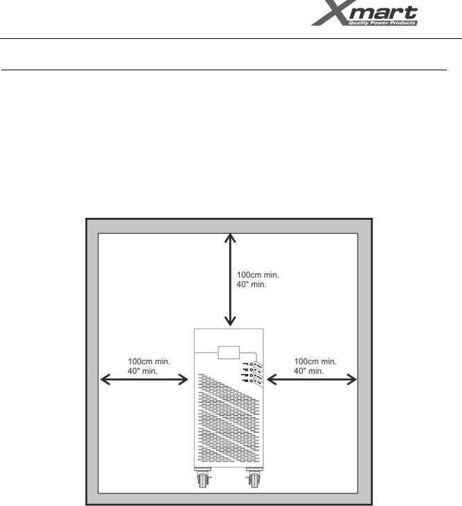
WARNING: Install the UPS in well ventilated locations and leave room enough between UPS and close objects and structures
WARNING: Do not connect to UPS equipments or devices that exceed its capacity, this would overload the UPS.
WARNING: This product has been designed to be used indoors protected from water, direct sun light, dust and extreme temperature.
WARNING: Do not put any object on the UPS; do not apply any force over UPS. Do not cover UPS ventilation.
WARNING: This UPS must be connected to appropriate electrical service according to selected model. Technical specs sticker in the UPS
shows the UPS power ratings. DO NOT connect this UPS to any of its own power outlets, this could damage the unit permanently.
WARNING: Connect only computer related equipments to this UPS. DO NOT connect medical equipments or critical availability equipments to
this UPS. DO NOT connect AC motor based equipments. DO NOT connect home appliances (ovens, vacuum cleaners, refrigerators, etc.) to this
UPS.
www.xmart-ups.com |
130612-OPTIMA-33 10K/20K (ENGLISH) - 5 |

USER MANUAL - OPTIMA-33 10K / 20K / 30K
SITE INSPECTION AND INSTALLATION CONDITIONS
REGULATIONS AND LEGAL DIRECTIVES
It is necessary to check that installation site, wiring and power protection in the installation supplied by end user, fulfill technical parameters required by UPS.
A particular installation might accomplish with UPS requirements but not with local directives and regulations.
The end user and/or electrical contractor will be responsible of watching for complying with electrical regulations and normative during electrical installation managed by end user.
Inspection performed by installation technician is not intended to confirm regulations and directives accomplishing but only with technical needs for optimal UPS operation.
SITE INSPECTION
•During transport of this UPS from a cold place to a warmer and more humid one, some condensation could be generated. Leave the UPS for at least 2 hours to climate to new installation site.
•Do not install the UPS outdoors or near water sources nor in wet environment
•Do not install the UPS in sites exposed to sun light or heat sources. Temperature at operation site should never rise over 35 ºC. Batteries’ life shortens over 25 ºC.
•Installation site must be dry, fresh, free of dust, fibers and any other objects (conductors or not) suspended in the air that could get into the UPS thru the ventilation system (Fan).
•Do not block UPS ventilations
UPS INPUT AND OUTPUT POWER LINES PROTECTION
AC LINES PROTECTIONS DEVICES:
All UPS Inputs and outputs must be protected by circuit breakers and current leak protections. Protection capacity and type must fulfill local regulations as well as directives from this manual. Grounding must be according to local directives as well.
DC PROTECTIONS DEVICES:
For Ex models (with external batteries) there must be also DC Circuit Breakers between UPS and battery bank.
Some Models include a DC breaker on the rear panel for external battery pack protection; otherwise an external DC Circuit breaker must be installed.
MATERIALS AND ELECTRICAL DEVICES
WARNING: Verify that all electrical lines involved in installation are open circuits and free of dangerous voltages before starting inspection tasks. All switches related to these electrical lines must be in “OFF” position before starting UPS installation. After disconnecting power from electrical lines involved in installation, check again with a digital voltmeter that are free of dangerous voltages.
IMPORTANT: Warning label must be placed on primary involved circuit breakers to alert there are maintenance personnel working on these circuits to avoid accidental actuation on involved breakers.
www.xmart-ups.com |
130612-OPTIMA-33 10K/20K (ENGLISH) - 6 |
USER MANUAL - OPTIMA-33 10K / 20K / 30K
TOWER UPS INSTALLATION
SITE CONSIDERATIONS
*This product has been designed to be used indoors, protected from water, direct sun light, dust and extreme temperature.
*Install the UPS in well ventilated location or air conditioned room. Temperature must be always in acceptable range according to technical specifications table of this manual. It is strongly recommendable controlled room temperature between 21ºC to 24ºC for longer battery and UPS life.
*There must be minimum 1 meter free room distance between UPS and any wall or object. It will allow better ventilation and it will allow service UPS when required.
*Do not put any object on the UPS; do not apply any force over UPS. Do not cover UPS ventilation.
ELECTRICAL REQUIREMENTS (MANDATORY)
*All Power lines must be protected by magneto-thermal protection devices against over current (breakers) with capacity and technology appropriate to effectively accomplish its function as indicated in this manual. Moreover, installation grounding must be correct.
*This UPS must be connected to appropriate electrical service according to selected model. Technical specs sticker in the UPS shows the UPS power ratings. DO NOT connect this UPS to any of its own power outlets, this could damage the unit permanently.
*If external battery cabinets are connected to UPS, it is necessary to install one DC breaker between UPS and each external battery cabinet. Original External Battery cabinets normally include its own input breaker.
LEAK CURRENT PROTECTION
In many countries, now a day, it is legally required to install protections against current leakage to protect human beings in cases of leaks o discharges to ground. It is responsibility of the end user and/or electrical contractor selecting and including these protection devices in the electrical circuit of the UPS.
www.xmart-ups.com |
130612-OPTIMA-33 10K/20K (ENGLISH) - 7 |

USER MANUAL - OPTIMA-33 10K / 20K / 30K
CIRCUIT BREAKERS AND WIRING SELECTION
Breakers and Gauge of the wires used in the installation must be rated to drive current values in Amps as indicated in below tables.
NOTE every country has its local electrical requirements and regulations. If local electrical regulations require higher rates than suggested values in this section, please follow local regulations.
400/230VAC |
INPUT |
OUTPUT |
EXT. BATT |
|
MODEL |
BREAKER & WIRING |
BREAKER & WIRING |
BREAKER & WIRING |
|
|
|
|
|
|
|
Breaker: 32A AC (Curve D) |
Breaker: 32A AC (Curve D) |
Breaker: 50Amps DC (Curve C) |
|
|
Max. Nominal Current (Ph-N): |
Max. Nominal Current (Ph-N): |
|
|
10KVA |
- 19A in normal mode (@200V) |
- 15A in normal mode (@220V) |
Wiring (min. recommended size): |
|
Wiring (min. recommended size): |
Wiring (min. recommended size): |
* 8 AWG (10mm2) |
||
(400/230VAC) |
||||
* Phase: 10AWG (6 mm2) |
* Phase: 10AWG (6 mm2) |
|
||
|
|
|||
|
* Neutral: 8AWG (10 mm2) |
* Neutral: 8AWG (10 mm2) |
|
|
|
* Ground: 8AWG (10 mm2) |
* Ground: 8AWG (10 mm2) |
|
|
|
|
|
|
|
|
Breaker: 50 Amps AC (Curve D) |
Breaker: 50 Amps AC (Curve D) Max. |
Breaker: 100Amps DC (Curve C) |
|
|
Max. Nominal Current (Ph-N): |
Nominal Current (Ph-N): |
|
|
20KVA |
- 38A in normal mode (@200V) |
- 30A in normal mode (@220V) |
|
|
Wiring (min. recommended size): |
Wiring (min. recommended size): |
Wiring (min. recommended size): |
||
(400/230VAC) |
||||
* Phase: 8 AWG (10 mm2) |
* Phase: 8 AWG (10 mm2) |
* 6 AWG (16mm2) |
||
|
||||
|
* Neutral: 6 AWG (16 mm2) |
* Neutral: 6 AWG (16 mm2) |
|
|
|
* Ground: 6 AWG (16 mm2) |
* Ground: 6 AWG (16 mm2) |
|
|
|
|
|
|
|
|
Breaker: 63 Amps AC (Curve D) |
Breaker: 63 Amps AC (Curve D) Max. |
Breaker: 150Amps DC (Curve C) |
|
|
Max. Nominal Current (Ph-N): |
Nominal Current (Ph-N): |
|
|
30KVA |
- 56A in normal mode (@200V) |
- 45A in normal mode (@220V) |
|
|
Wiring (min. recommended size): |
Wiring (min. recommended size): |
Wiring (min. recommended size): |
||
(400/230VAC) |
||||
* Phase: 8 AWG (10 mm2) |
* Phase: 8 AWG (10 mm2) |
* 3 AWG (35mm2) |
||
|
||||
|
* Neutral: 6 AWG (16 mm2) |
* Neutral: 6 AWG (16 mm2) |
|
|
|
* Ground: 6 AWG (16 mm2) |
* Ground: 6 AWG (16 mm2) |
|
|
|
|
|
|
Recommended cable size according to 1999 NEC (301-17) based on 30ºC air ambient temperature for single cable.
WARNING:
Above wiring and breakers rates are only a suggestion. The wire size is strongly affected by diverse factors such as: Operation temperature, wire length, type of wire, quantity of conductors and kind of installation. Electrical contractor must assure an appropriate selection for wire and protection devices sizing for complying with local regulations for electrical installations. Wiring colors must be selected according to local directives and regulations
www.xmart-ups.com |
130612-OPTIMA-33 10K/20K (ENGLISH) - 8 |
USER MANUAL - OPTIMA-33 10K / 20K / 30K
208/120VAC |
INPUT |
OUTPUT |
EXT. BATT |
|
|
Breaker: 63 Amps AC (Curve D) |
Breaker: 63 Amps AC (Curve D) |
Breaker: 50 Amps DC (Curve C) |
|
|
Max. Nominal Current (Ph-N): |
Max. Nominal Current (Ph-N): |
|
|
10KVA |
- 38A in normal mode (@100V) |
- 30A in normal mode (@110V) |
|
|
Wiring (min. recommended size): |
Wiring (min. recommended size): |
Wiring (min. recommended size): |
||
(208/120VAC) |
||||
Phase: 8 AWG (10 mm2) |
Phase: 8 AWG (10 mm2) |
8 AWG (10mm2) |
||
|
||||
|
Neutral: 6 AWG (16 mm2) |
Neutral: 6 AWG (16 mm2) |
|
|
|
Ground: 6 AWG (16 mm2) |
Ground: 6 AWG (16 mm2) |
|
|
|
|
|
|
|
|
Breaker: 80 Amps AC (Curve D) |
Breaker: 80 Amps AC (Curve D) |
Breaker: 100Amps DC (Curve C) |
|
|
Max. Nominal Current (Ph-N): |
Max. Nominal Current (Ph-N): |
|
|
20KVA |
- 75A in normal mode (@100V) |
- 60A in normal mode (@110V) |
|
|
Wiring (min. recommended size): |
Wiring (min. recommended size): |
Wiring (min. recommended size): |
||
(208/120VAC) |
||||
Phase: 6 AWG (16 mm2) |
Phase: 6 AWG (16 mm2) |
* 6 AWG (16mm2) |
||
|
||||
|
Neutral: 4 AWG (25 mm2) |
Neutral: 4 AWG (25 mm2) |
|
|
|
Ground: 4 AWG (25 mm2) |
Ground: 4 AWG (25 mm2) |
|
|
|
|
|
|
|
|
Breaker: 125 Amps AC (Curve D) |
Breaker: 125 Amps AC (Curve D) Max. |
Breaker: 150Amps DC (Curve C) |
|
|
Max. Nominal Current (Ph-N): |
Nominal Current (Ph-N): |
|
|
30KVA |
- 111A in normal mode (@100V) |
- 90A in normal mode (@110V) |
|
|
Wiring (min. recommended size): |
Wiring (min. recommended size): |
Wiring (min. recommended size): |
||
(208/120VAC) |
||||
Phase: 3 AWG (35 mm2) |
Phase: 3 AWG (35 mm2) |
* 3 AWG (35mm2) |
||
|
||||
|
Neutral: 2 AWG (35 mm2) |
Neutral: 2 AWG (35 mm2) |
|
|
|
Ground: 2 AWG (35 mm2) |
Ground: 2 AWG (35 mm2) |
|
|
|
|
|
|
Recommended cable size according to 1999 NEC (301-17) based on 30ºC air ambient temperature for single cable.
WARNING:
Above wiring and breakers rates are only a suggestion. The wire size is strongly affected by diverse factors such as: Operation temperature, wire length, type of wire, quantity of conductors and kind of installation. Electrical contractor must assure an appropriate selection for wire and protection devices sizing for complying with local regulations for electrical installations. Wiring colors must be selected according to local directives and regulations
www.xmart-ups.com |
130612-OPTIMA-33 10K/20K (ENGLISH) - 9 |
USER MANUAL - OPTIMA-33 10K / 20K / 30K
4.- UPS INSTALLATION: SINGLE UPS - TERMINAL BLOCK
AC LINES CONNECTION PROCEDURE
•Make sure the UPS is Off before starting the installation.
•Remember to check all wires to be connected are not powered (including external batteries).
UPS terminal block preparation
Remove cover of terminal block at the UPS rear panel, identified as "10" in rear panel section of this manual
UPS Input wires must come from electric panel board and they must be protected by a circuit breaker protection device.
UPS Input and Output Connection
Connect input and output ground wires to proper place on the UPS chassis or terminal block. Ground wires must be FIRST to be connected and LAST to be disconnected.
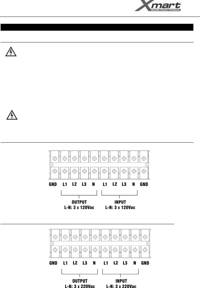
Connect UPS input and output wires according to your UPS model as described in following figures:
IMPORTANT NOTE: If terminal block information printed on rear panel of the UPS is different to information given in this manual, please follow terminal block information printed on UPS.
OPTIMA-33 208/120VAC
OPTIMA-33 400/230VAC
www.xmart-ups.com |
130612-OPTIMA-33 10K/20K (ENGLISH) - 10 |
USER MANUAL - OPTIMA-33 10K / 20K / 30K
EXTERNAL BATTERY CABINETS – CONNECTION PROCEDURE
UPS Tower type
WARNING
Make sure EXBATT model to be connected is compatible with UPS model. For OPTIMA-33 models, battery pack voltage is 240Vdc. Measure and verify DC voltage supplied by battery pack before making connections.
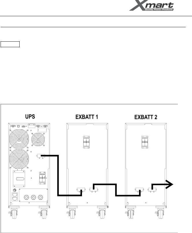
1.- Check all DC breakers are in OFF position
2.- Remove all DC connector covers in UPS and EXBATT cabinets
3.- Using appropriate cable (supplied with the EXBATT) connect UPS with EXBATT 1. In case of more than 1 EXBATT connect EXBATT 1 with EXBATT 2 and so on until last EXBATT.
4.- Activate DC breakers one by one in EXBATT cabinets to connect EXBATT batteries with internal UPS Main batteries.
www.xmart-ups.com |
130612-OPTIMA-33 10K/20K (ENGLISH) - 11 |
 Loading...