


XD 9002D
ADKDSWDHD 06/15/2015
XLT Oven & AVI Hood
Technical/Rough-In Specifications for Gas & Electric Ovens & Hoods
This appliance is for professional use by qualified personnel. This appliance must be installed by qualified persons in accordance with the regulations in force. This appliance must be installed with sufficient ventilation to prevent the occurrence of unacceptable concentrations of substances harmful to health in the room in which it is installed. This appliance needs an unobstructed flow of fresh air for
CAUTION satisfactory combustion & must be installed in a suitably ventilated room in accordance with current regulations. This appliance should be serviced by qualified personnel at least every 12 months or sooner if heavy use is expected.
Electronic copies of the Installation & Operation Manual, Parts & Service Manual, Architectural Drawings, & a list of International Authorized Distributors are available at: www.xltovens.com
For use with the following XLT Gas & Electric Oven Versions: For use with the following AVI Hood Versions:
Australian (AE) |
D |
Standard (S) |
D |
Korea (K) |
D |
World (W) |
D |
Standard (S) |
D |
|
|
World (W) |
D |
|
|
2000887
XLT Ovens
PO Box 9090
Wichita, Kansas 67277
US: 888-443-2751 FAX: 316-943-2769 INTL: 316-943-2751 WEB: www.xltovens.com
|
|
|
|
|
2 |
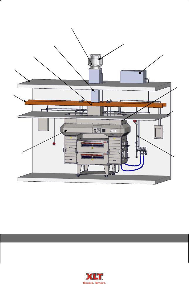
TYPICAL STORE INSTALLATION |
|
|
|
|
|
Roof Curb
Welded Duct |
Exhaust Fan |
|
Duct Wrapper
Roof
Roof Joist
Fire
Suppression 
Box
AVI Hood
XLT Oven 
Roof Top Unit (RTU)
Valance
Ceiling
 Service
Panel
Gas
Service
 Floor
Floor
Typical Store Installation
Revision History Table
Revision |
Comments |
Date |
|
|
|
C |
Revised (KW/HR) Rating |
01/14/2015 |
|
|
|
D |
Removed All 3270 and 3870 Single Burner Information |
06/15/2015 |
|
|
|
Technical Support US: 888-443-2751 |
Technical Support INTL: 316-943-2751 |
TABLE OF CONTENTS |
3 |
Typical Store Installation ............................................................................................................. |
2 |
Warning & Safety Information..................................................................................................... |
4 |
Descriptions.................................................................................................................................. |
5 |
Oven Electrical Requirements...................................................................................................... |
6 |
Hood Electrical Requirements...................................................................................................... |
7 |
Gas Requirements......................................................................................................................... |
8 |
Fire Suppression ......................................................................................................................... |
10 |
Oven Dimensions ....................................................................................................................... |
12 |
Hood Dimensions ....................................................................................................................... |
14 |
Ventilation Requirements........................................................................................................... |
16 |
Pre-Installation Checklist ........................................................................................................... |
17 |
Exhaust Fan Specifications ........................................................................................................ |
18 |
This document is intended for use by general contractors, architects, sub-contractors and store owners to provide information during the planning & pre-installation phases of installing XLT Ovens & AVI Hoods. Please refer to the XLT Installation & Operation Manual for instructions on the assembly and utility hook-up phase of the project.
The process of getting a facility configured to owners’ expectations can be difficult and frustrating, or it can be accomplished smoothly and on time. The information presented here can help move the “D” portion of the image below towards “on time” and “under budget”.
The end goal is to obtain an occupancy permit from the Authority Having Jurisdiction (AHJ). A thorough understanding of the prevailing local codes can expedite this process and prevent unexpected surprises. Proper planning and execution will allow the successful installation of new ovens and hood in an existing store overnight with NO downtime.
The purpose of building codes is to provide minimum standards for the protection of life, limb, property, environment, the safety and welfare of the consumer, general public, and the owners and occupants of structures regulated by codes. Building codes are constantly changing and they can vary by state, county, city , town, and/or borough. While some states like California, Florida, Massachusetts, Michigan, and New York have their own set of building codes, most states have adopted the International Code Council (ICC) series of codes. Always check with your local building code department in order to learn which codes are being used and how they will affect you and your construction project. You may want to start by contacting your local inspection department, office of planning and zoning, and/or department of permits.
The information presented here has been proven to satisfy the latest code requirements.
Technical Support US: 888-443-2751 |
Technical Support INTL: 316-943-2751 |
|
|
|
|
|
4 |
WARNING & SAFETY INFORMATION |
|
The information contained in this manual should be distributed and read by all parties involved in procuring and installing this equipment prior to any work being performed.
To ensure an smooth installation the pre-installation checklist found in the back of this manual must be reviewed before the XLT equipment is scheduled to arrive.
It is also advisable that a schedule be developed by the general contractor to ensure all activities are completed in the proper sequence and performed by the proper personnel.
XLT will assist in the coordination of disseminating information and scheduling the delivery of equipment. Please contact XLT or your distributor for additional assistance.
XLT wants you to be totally satisfied with every aspect of owning & using your oven & hood. Your feedback, both positive & negative, is very important to us as it helps us understand how to improve our products & our company. Our goal is to provide you, our customer, with equipment that we can be proud to build & you can be proud to own.
To receive technical support for the oven or hood you purchased, contact XLT anytime day or night, 365 days per year. Please be prepared to provide the Model & Serial Number.
Installation of all gas appliances & ventilation exhaust hoods should only be performed by a qualified professional who has read & understands these instructions & is familiar with proper safety precautions. Read this manual thoroughly before in-
WARNING stalling or servicing this equipment.
All electrical connections must be made by a qualified electrician in accordance with NEC, OSHA, and all applicable national, state, and local codes.
All plumbing connections must be made by a qualified plumber in accordance with all applicable national, state, and local codes.
All HVAC components must be made by a qualified mechanical contractor in accordance with national, state, and local codes.
All ovens must have their own separate electrical circuit.
All systems in the AVI Hood must have their own separate electrical circuit.
Each XLT Oven must have it’s own gas shut-off valve.
XLT Ovens reserves the right to make changes in design & specifications, and/or make additions to or improvements to its product without imposing any obligations upon itself to install them in products previously manufactured.
Technical Support US: 888-443-2751 |
Technical Support INTL: 316-943-2751 |
|
|
DESCRIPTIONS |
5 |
|
|
This manual covers the following XLT GAS Oven & AVI Hood models:
|
|
|
|
Ovens |
Hoods |
X3D-1832-xxxxx |
H3D-1832-xxxxx |
X3D-2440-xxxxx |
H3D-2440-xxxxx |
X3D-3240-xxxxx |
H3D-3240-xxxxx |
X3D-3255-xxxxx |
H3D-3255-xxxxx |
X3D-3270-xxxxx-2B |
H3D-3270-xxxxx-2B |
X3D-3855-xxxxx |
H3D-3855-xxxxx |
X3D-3870-xxxxx-2B |
H3D-3870-xxxxx-2B |
The first 2 digits of the model number represent the conveyor width & the last two digits indicate the bake chamber length. The ovens may be used as a single, double, or triple oven stack configuration. All ovens are available in (NAT) Natural Gas or (LP) Liquid Petroleum gas. (Electric ovens are also available). The 3270-2B & 3870-2B models have two burners, one on each side, & have two control boxes. All other models have only a single burner with a single control box that can be supplied on either end. All models can be configured for a split belt conveyor.
All installations must conform to local building & mechanical codes.
Utilities must be easily accessible when the ovens are in the installed position. Do not install utilities directly behind the ovens.
In Australia follow AS/NZS 3000 Wiring and AS5601 Gas Installation.
Additional restrictions apply. Please see the XLT Installation & Operation Manual for more details.
CERTIFICATIONS
For a complete list of Certifications, please see the XLT Installation & Operation Manual.
Technical Support US: 888-443-2751 |
Technical Support INTL: 316-943-2751 |
|
|
|
|
|
6 |
OVEN ELECTRICAL REQUIREMENTS |
|
|
|
|
|
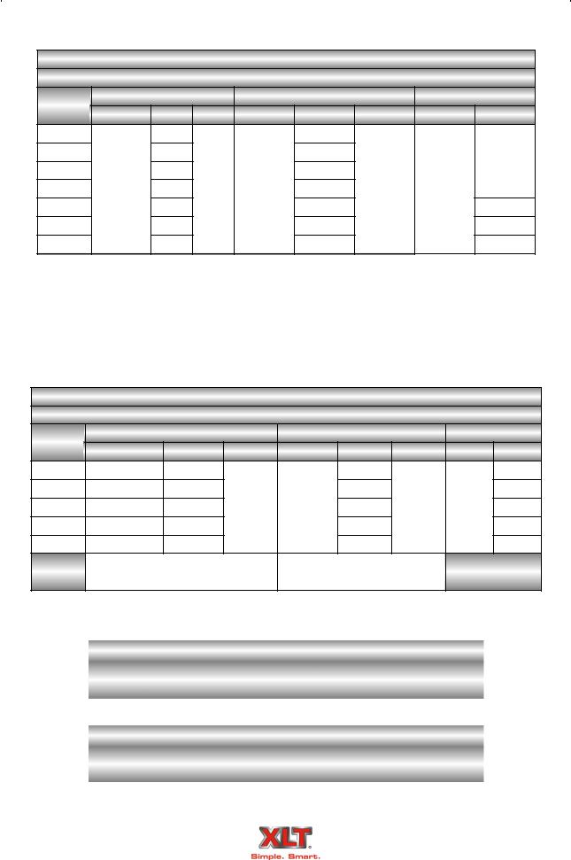
Gas Oven Electrical Requirements
Per EACH Oven
Oven |
|
Standard |
Australia & World |
|
Korea |
||||
Model |
Volts AC Amps |
Hertz Volts AC |
Amps |
Hertz |
Volts AC Watts |
||||
1832 |
|
|
6 |
|
3 |
|
|
|
|
2440 |
|
|
6 |
|
3 |
|
|
660 |
|
3240 |
|
|
6 |
220/230/ |
3 |
|
|
||
120 VAC |
|
220 VAC |
|||||||
3255 |
6 |
50/60 240 VAC |
3 |
50/60 |
|||||
1Φ |
|
1Φ |
|
||||||
3270-2B |
|
12 |
1Φ |
6 |
|
1320 |
|||
|
|
|
|
||||||
3855 |
|
|
6 |
|
3 |
|
|
660 |
|
3870-2B |
|
|
12 |
|
6 |
|
|
1320 |
|
FOR EACH GAS OVEN:
A separate 20 amp circuit breaker must be provided for each oven deck.
Electrical connections must be accessible when the ovens are in the installed position.
Electrical connections must meet all local code requirements.
Electric Oven Electrical Requirements
Per EACH Oven
Oven |
STANDARD |
|
WORLD |
|
ALL |
|||
Model |
Volts AC |
Amps |
Hertz |
Volts AC |
Amps |
Hertz |
Phase |
KW |
1832 |
208/240 |
44/38 |
|
|
24 |
|
|
16 |
2440 |
208/240/480 |
75/65/33 |
|
|
41 |
|
|
27 |
3240 |
208/240/480 |
75/65/33 |
60 |
380 |
41 |
50 |
3 |
27 |
3255 |
208/240/480 |
88/77/38 |
|
|
48 |
|
|
32 |
3855 |
208/240/480 |
88/77/38 |
|
|
48 |
|
|
32 |
|
4 Wire Service - L1, L2, L3 |
5 Wire Service - L1, L2, L3 |
|
|
||||
|
+1 Ground (per oven) |
N +2 Grounds (per oven) |
|
|
||||
A DISCONNECT MUST BE INSTALLED IN ACCORDANCE TO LOCAL BUILDING CODES:
|
Conveyor Belt Times |
||
Oven |
MINIMUM |
MAXIMUM |
|
Models |
|||
|
|
||
All |
1:30 |
17:00 |
|
|
|
Oven Operating Temperature Range |
|
|
|
Oven |
MINIMUM |
MAXIMUM |
|
|
Models |
|
||
|
|
|
|
|
|
All |
400° F |
590° F |
|
|
205° C |
310° C |
|
|
|
|
|
||
Technical Support US: 888-443-2751 |
Technical Support INTL: 316-943-2751 |
|||
|
|
HOOD ELECTRICAL REQUIREMENTS |
7 |
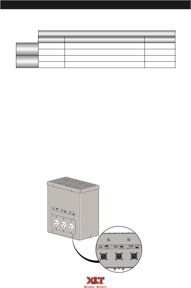
Inputs into VFD Box
|
|
|
AVI Hood Electric Utility Specifications |
|
||||
|
# of Circuits |
|
|
Rating |
Purpose |
|||
Standard |
1 |
|
208/240 VAC, 1 Phase, 60 Hz, 6 Amp |
VFD Controller |
||||
up to 3 |
120 |
VAC, 1 |
Phase, 60 |
Hz, 20 Amp |
Ovens |
|||
|
||||||||
World |
1 |
|
230 |
VAC, 1 |
Phase, 50 |
Hz, 6 Amp |
VFD Controller |
|
up to 3 |
230 |
VAC, 1 |
Phase, 50 |
Hz, 10 Amp |
Ovens |
|||
|
||||||||
Outputs from Junction Box
The AVI Hood system provides:
One (1) switching outputs for HVAC damper and/or dedicated unit. (Optional 2-3 add-on)
One (1) 230 VAC, 10 Amp, variable frequency, three phase power output for the ventilation exhaust fan.
Up to Three (3) receptacles for ovens. (Gas Only)
One (1) 120 VAC fire alarm signal for Standard hoods, or one (1) 24 VAC fire alarm signal for World Hoods
For Oven & Hood installations with the VFD option, all electrical connections are made in the junction box located on the right rear corner of the upper portion of the hood. Power for the exhaust fan is provided from the VFD controller. Optional fire suppression & MUA damper relay connections may also be made in the junction box.
For Oven & Hood installations without the VFD option only the lighting and oven receptacle connections are made in the junction box. Ovens without a AVI hood are plugged into the receptacles on the wall.
Technical Support US: 888-443-2751 |
Technical Support INTL: 316-943-2751 |
 Loading...