


Performance helmets
FOLLOW US
facebook.com/NolanGroup
SICUREZZA E ISTRUZIONI D’USO
SAFETY AND INSTRUCTIONS FOR USE
SICHERHEIT UND GEBRAUCHSANLEITUNG
SÉCURITÉ ET INSTRUCTIONS D’U TILIS ATION
SEGURIDAD E INSTRUCCIONES
SEGURANÇA E INSTRUÇÕES DE USO
VEILIGHEID EN GEBRUIKSA ANWIJZING
SIKKERHED OG AN VENDELSE

2
CONGRATULAZIONI... per l’acquisto del tuo nuovo casco.
Il design, l’ergonomia, il comfort, l’aerodinamicità, i comandi semplici e funzionali; il tutto
è stato progettato e realizzato per ottenere un prodotto moderno e dalle massime prestazioni, in grado di soddisfare le più elevate esigenze in termini di sicurezza e comfort.
SICUREZZA E NORME D’USO
• IMPORTANTE!
- Leggi questo libretto e tutti gli altri documenti inclusi prima di utilizzare il tuo
casco perché contengono importanti informazioni che ti aiuteranno ad utilizzare
al meglio il casco, in tutta sicurezza e semplicità.
- Non attenersi a queste istruzioni potrebbe ridurre la protezione data dal casco e
quindi la tua incolumità.
• UTILIZZO DEL CASCO
- Il casco è progettato in modo specifico per l’uso motociclistico e ciclomotoristico;
perciò non garantisce la medesima protezione per un uso diverso.
- In caso d’incidente, il casco è un elemento di protezione che permette di limitare
lesioni e danni alla testa. Ma nonostante ciò, non è in grado da solo di eliminare i rischi
di ferite gravi e/o mortali, le quali dipendono dalle diverse dinamiche specifiche dell’impatto; quindi guida con prudenza.
- Indossa sempre il tuo casco ben allacciato alla guida di motocicli, in modo da sfruttarne
tutta la protezione disponibile.
- Non indossare mai sciarpe sotto il sistema di allacciatura o copricapo di qualsiasi tipo
sotto il casco.
- Il casco può attutire i rumori del traffico. Comunque, in tutti i casi, assicurati di percepire bene i suoni necessari quali clacson e sirene di emergenza.
- Tienilo sempre lontano da fonti di calore, come ad esempio la marmitta di scarico,
l’alloggiamento del bauletto o in un abitacolo di un mezzo di trasporto.
- Non modificare e/o manomettere il casco (anche solo in parte) per nessun motivo.
Monta solo accessori e/o ricambi originali adatti al tuo specifico modello di casco.
- Danni al casco, che possono essere causati da cadute accidentali, non sempre sono
ben visibili; ogni casco che abbia subito un urto violento deve essere sostituito.
- In caso di dubbi sull’integrità e sicurezza del casco, astieniti dall’utilizzarlo e rivolgiti ad
un rivenditore autorizzato, per farlo ispezionare.
• SCELTA DEL CASCO
Taglia:
- per individuare la taglia corretta, indossa caschi di diverse misure, e scegli quello che
risulta saldamente a posto, ma in tutto comfort.
- un casco troppo grande può scendere sino a coprire gli occhi, oppure ruotare lateralmente
durante la guida.
- tienilo in testa per alcuni minuti e verifica che non ci siano zone di pressione, che alla
lunga possono provocare indolenzimento o mal di testa.
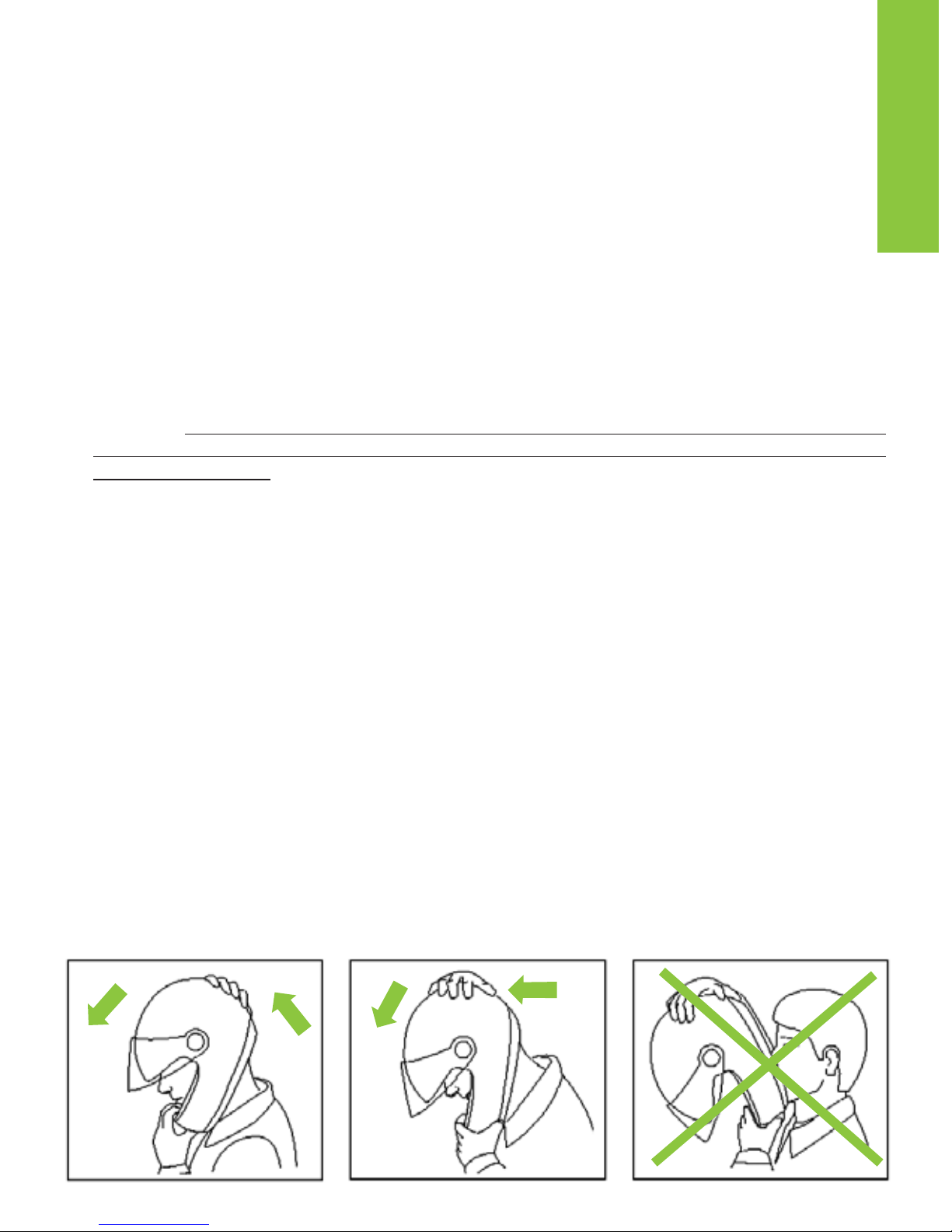
Scalzamento:
- con il casco indossato e il cinturino ben allacciato, prova a sfilarti il casco come indicato in figura (Fig. A). Infatti, in caso di incidente, gli impatti ricevuti da diverse direzioni, tendono a far scalzare il casco dalla testa.

3
ITALIANO
- il casco non deve ruotare, muoversi liberamente sulla testa o sfilarsi. In caso contrario
regola la lunghezza del cinturino o cambia taglia del casco. Ripeti di nuovo il test.
Sistema di ritenzione:
- il sistema di ritenzione (cinturino) è regolato di serie con una lunghezza standard;
prima di utilizzarlo verifica la corretta pre-regolazione.
- assicurati sempre che il cinturino sia bene allacciato e stretto in modo da tenere il
casco fermo sulla testa. In qualsiasi caso, prima di partire, assicurati che il cinturino sia ben stretto sotto il mento, il più indietro possibile verso la gola, ma senza che
sia scomodo.
- la giusta tensione del cinturino ti deve permettere una respirazione e una deglutizione normale, ma senza riuscire a far passare un dito fra cinturino e gola.
- Attenzione: il bottone eventualmente presente sul cinturino ha esclusivamente la
funzione di impedire lo sventolio della parte terminale dello stesso, dopo che si è
provveduto ad allacciarlo correttamente.
• VISIERA
- Se la visiera è danneggiata e presenta graffi marcati che riducono la visibilità, è probabile
che il trattamento protettivo sia stato compromesso, e pertanto la visiera deve essere
sostituita.
- Non applicare adesivi e vernici.
- La visiera è utilizzabile esclusivamente per il modello di casco per cui è stata
progettata.
• MANUTENZIONE E PULIZIA
- Danni al casco, che possono essere causati da cadute accidentali, non sempre sono
ben visibili; ogni casco che abbia subito un urto violento deve essere sostituito.
- Attenzione: il casco e la visiera possono essere seriamente danneggiati da alcune
sostanze comuni senza che il danno sia visibile. Per le operazioni di pulizia del casco
e della visiera, utilizza solo acqua tiepida e sapone neutro; asciuga a temperatura
ambiente, a riparo dal sole e/o da fonti di calore.
- Attenzione: non utilizzare mai benzina, diluente, benzolo, solventi o altre sostanze chimiche perchè possono:
• danneggiare irrimediabilmente il casco;
• modificare le proprietà ottiche, ridurre le proprietà meccaniche ed indebolire il tratta-
mento protettivo della visiera.
Fig. A

ISTRUZIONI D’USO
Il casco X-1003 può essere utilizzato in due configurazioni (mentoniera chiusa - P / mentoniera aperta - J). L utilizzo del casco nella configurazione P, (con mentoniera e visiera chiuse), offre ovviamente il più elevato livello di protezione rispetto alla configurazione J (con
mentoniera e visiera aperte).
• SISTEMA DI APERTURA DELLA MENTONIERA
X-1003 è dotato dell’esclusivo sistema di apertura della mentoniera “Dual Action” che, posizionato al centro della mentoniera, ne consente l’apertura con una sola mano e ne evita
l’apertura involontaria: solo dopo aver azionato la prima leva di sblocco è possibile aprirla
agendo sulla seconda leva.
Nota: la configurazione aperta con mentoniera e VPS alzati è consigliata per una più
agevole calzata del casco.
1 APERTURA
1.1 Spingere verso l’esterno la leva rossa di sblocco facendola ruotare con il pollice (Fig. 1).
1.2 Posizionare l’indice sopra la leva di apertura e spingerla verso il basso, in modo da
sbloccare la mentoniera (Fig. 2).
1.3 Tirare in avanti la mentoniera apribile ed accompagnarla nel suo movimento di rotazio-
ne verso l’alto (Fig. 3).
ATTENZIONE: se il casco viene utilizzato in configurazione J (con mentoniera aperta)
si consiglia di posizionare il cursore laterale sinistro di blocco in posizione “J” (vedi
istruzioni Configurazione P/J - Fig. 5, cursore in alto) per assicurare la mentoniera in
posizione sollevata.
2 CHIUSURA
ATTENZIONE:
Per poter chiudere la mentoniera verificare che il cursore laterale di
blocco si trovi in posizione P come illustrato in fig. 4 (cursore in basso).
2.1 Tirare la mentoniera verso il basso accompagnandola nel suo movimento di rotazione
fino a sentire gli scatti del meccanismo di chiusura.
2.2 Accertarsi che la mentoniera sia correttamente agganciata.
• CONFIGURAZIONE P/J
Fig. 4 (cursore in basso)
Quando il cursore laterale di blocco si trova nella posizione “P” (Fig. 4, cursore in basso) la
mentoniera può essere aperta e/o chiusa.
Fig. 5 (cursore in alto)
Quando il cursore laterale di blocco è nella posizione “J” (Fig. 5, cursore in alto), la mentoniera non può essere chiusa, rimanendo bloccata in posizione aperta.
ATTENZIONE! In questa configurazione la mentoniera non può essere richiusa.
Non forzare la chiusura della stessa perché ciò potrebbe determinare dei danni al meccanismo di chiusura del casco. Per procedere alla chiusura della mentoniera è necessario spostare il cursore di blocco in posizione P (Fig. 4, cursore in basso).
ATTENZIONE!!!
- Il livello di protezione di questo casco durante la guida del veicolo è in funzione della
configurazione adottata dall’utente: protezione completa con mentoniera e visiera chiuse, protezione parziale con mentoniera e/o visiera aperte.
4

5
- Non smontare e/o manomettere le viti di fissaggio della mentoniera alla calotta.
- Non utilizzare il casco privo di mentoniera.
- Non utilizzare il casco in caso di malfunzionamento della mentoniera, rivolgersi imme-
diatamente ad un rivenditore autorizzato X-lite.
• SCRATCH RESISTANT VISOR: VISIERA IN RESISTENTE AL GRAFFIO
1 SMONTAGGIO (Fig. 6)
1.1 Chiudere la mentoniera e aprire completamente la visiera in posizione aperta.
1.2 Tenendo premuto il tasto sblocco visiera (A) far scorrere in avanti la visiera fino allo
scatto.
1.3 Svincolare i ganci visiera (B1 e B2) dalla loro sede.
1.4 Ripetere le precedenti operazioni dall’altro lato del casco.
2 MONTAGGIO (Fig. 7)
2.1 Chiudere la mentoniera e sistemare la visiera in posizione aperta posizionando i ganci
visiera (B1 e B2) in corrispondenza delle apposite sedi ricavate nel meccanismo visiera.
2.2 Inserire il gancio B1 nella apposita sede e premere la visiera contro la calotta in corri-
spondenza del gancio B2, azionando così il tasto sblocco visiera.
2.3 Far scorrere la visiera facendo scattare il sistema di blocco visiera.
2.4 Ripetere le precedenti operazioni dall’altro lato del casco.
ATTENZIONE!!!
- Verificare che il sistema funzioni correttamente. Aprire la visiera; alzando la mentoniera,
la visiera si deve chiudere automaticamente.
- Non utilizzare il casco senza aver montato correttamente la visiera.
- Se i meccanismi d’apertura e chiusura della visiera presentano malfunzionamenti o dan-
neggiamenti, rivolgersi ad un rivenditore autorizzato X-lite.
• DOUBLE ACTION
Il tasto Double Action in posizione neutra (centrale), come illustrato in figura 8, non ha alcuna influenza sul normale funzionamento della visiera in apertura e chiusura. Operando sul
tasto è possibile usufruire delle seguenti funzionalità aggiuntive:
Funzione disappannante
A casco indossato, aprire la visiera sino al primo scatto e premere il tasto Double Action
come indicato in Fig. 9. Infine richiudere la visiera.
In questa posizione, il meccanismo permette di mantenere la visiera in una posizione di minima apertura che migliora l’aerazione e facilita il disappannamento soprattutto a bassa velocità o nelle brevi soste.
Per disattivare il Double Action, premere il tasto come indicato in Fig. 10 riportandola in posizione neutra.
Funzione di blocco visiera
A casco indossato, chiudere la visiera e premere il tasto Double Action come indicato in
Fig. 10.
In questa posizione lo scatto di chiusura della visiera viene rafforzato in modo che, anche ad
alte velocità, aperture accidentali della stessa non si possano verificare.
Per disinserire il fermo visiera, premere il tasto come indicato in Fig. 9 riportandola in posizione neutra.
®

Attenzione! Durante l’utilizzo del casco, si possono presentare imprevisti di varia natura che
richiedono un’immediata apertura della visiera; si consiglia per tanto, di limitare l’uso della
funzione fermo-visiera.
Attenzione! In caso di emergenza si può disattivare il fermo visiera Double Action sollevando la visiera in modo tradizionale ed esercitando sulla linguetta della visiera stessa una forza
lievemente aggiuntiva rispetto a quella normalmente richiesta.
•
(Disponibile come accessorio opzionale)
1 MONTAGGIO VISIERINO INTERNO PINLOCK
®
1.1 Smontare la visiera.
1.2 Assicurarsi che la superficie interna della visiera sia pulita e verificare che le leve ester-
ne di regolazione dei perni siano disposte verso l interno.
1.3 Appoggiare il visierino interno Pinlock
®
alla visiera. ATTENZIONE: il profilo in silicone del
visierino Pinlock
®
deve essere a contatto con la superficie interna della visiera.
1.4 Inserire un lato del visierino interno Pinlock
®
in uno dei due perni della visiera e tenerlo
in posizione (Fig. 11).
1.5 Allargare la visiera e incastrare all altro perno il secondo lato del visierino interno Pinlock
®
(Fig. 12).
1.6 Rilasciare la visiera.
1.7 Rimuovere la pellicola di protezione dal visierino interno Pinlock
®
e controllare che tutto
il profilo in silicone del visierino sia aderente alla visiera.
1.8 Montare la visiera sul casco.
VERIFICA E REGOLAZIONE DEL TIRAGGIO DEL VISIERINO INTERNO
Verificare il corretto montaggio del sistema aprendo e chiudendo la visiera e controllando che
non ci sia movimento relativo tra visierino e visiera.
Qualora il visierino non fosse ben fissato alla visiera agire contemporaneamente su entrambe le leve esterne di regolazione facendole ruotare verso l’alto, in modo graduale e senza
eccedere, per aumentare il tiraggio (Fig. 13). Il massimo tiraggio si ottiene quando le leve
esterne di regolazione dei perni si trovano disposte verso l’esterno.
ATTENZIONE!!!
L’eventuale presenza di polvere tra le due visiere può causare dei graffi su entrambe le
superfici.
Visiere e Visierini Interni danneggiati da graffi possono ridurre la visibilità e devono essere
sostituiti.
Controllare periodicamente il corretto tiraggio del visierino interno per evitare che questo si
muova e possa causare dei graffi su entrambe le superfici.
Qualora durante l’uso si verificassero fenomeni di appannamento della visiera del casco e/o
formazione di condensa in zone comprese tra visiera e visierino, verificare il corretto montaggio e tiraggio del sistema.
Un tiraggio eccessivo e prematuro del visierino può determinare un’eccessiva aderenza di
quest’ultimo contro la superficie della visiera e/o deformazioni permanenti dello stesso con
conseguente impossibilità di eseguire correttamente successive regolazioni.
Utilizzi prolungati in particolari condizioni climatiche possono ridurre l’efficacia del sistema
determinando parziale appannamento o formazione di condensa sul visierino.
In tal caso, per ripristinare l’efficacia del sistema, rimuovere il visierino dalla visiera del casco
e farlo asciugare con aria secca e tiepida.
6

Situazioni di intensa sudorazione / respirazione, utilizzo in particolari condizioni climatiche
(basse temperature e/o umidità elevata e/o sbalzi di temperatura o pioggia copiosa) ed utilizzo intenso e prolungato possono determinare la riduzione dell’efficacia del sistema causando appannamento o formazione di condensa del visierino.
In queste situazioni, dopo l’utilizzo, per ripristinare l’efficacia del sistema, rimuovere il visierino dalla visiera del casco e farlo asciugare con aria secca e tiepida. La stessa prassi deve
essere eseguita per il casco che deve essere lasciato asciugare per eliminare eventuale umidità creatasi all’interno per le situazioni sopra descritte.
2 SMONTAGGIO VISIERINO INTERNO PINLOCK
®
2.1 Smontare la visiera equipaggiata con il visierino interno Pinlock®.
2.2 Allargare la visiera e sganciare il visierino interno Pinlok
®
dai perni (Fig. 12).
2.3 Rilasciare la visiera.
MANUTENZIONE E PULIZIA
Smontare il visierino interno Pinlock®dalla visiera. Usando un panno umido e morbido, pulire delicatamente con sapone neutro liquido. Rimuovere ogni traccia di sapone.
Lasciare asciugare il visierino senza strofinare aiutandosi con aria secca e tiepida.
Per mantenere inalterate nel tempo le caratteristiche del visierino, lasciare asciugare il casco
dopo l’utilizzo in luogo aerato e asciutto con la visiera aperta.
Tenere lontano da fonti di calore e conservare in luogo oscuro.
Non usare solventi o prodotti chimici.
• VISION PROTECTION SYSTEM (VPS)
Il nuovo ed esclusivo Vision Protection System (VPS) interno è uno schermo parasole stampato in e trattato scratch-resistant/fog-resistant, semplice e comodo da utilizzare:
basta abbassarlo per renderlo attivo o sollevarlo per escluderlo dal campo visivo.
È utile in tutte le situazioni, nei lunghi tratti extraurbani o per brevi percorsi cittadini.
L’innovativo sistema di aggancio, inoltre, permette di smontare e montare lo schermo parasole senza l’ausilio di attrezzi per le ordinarie operazioni di manutenzione e pulizia.
FUNZIONAMENTO DEL VPS
Il meccanismo del VPS permette, con un semplice movimento ed in modo indipendente dalla
visiera, di rendere attivo lo schermo parasole abbassandolo sino ad impegnare parzialmente il campo visivo della visiera, determinando la desiderata riduzione della trasmittanza della
luce. In ogni momento, sempre con un semplice movimento ed in modo indipendente dalla
visiera, il VPS può essere poi disattivato ed essere quindi rapidamente risollevato sino a ripristinare le normali condizioni di visibilità e protezione offerte dalla visiera omologata del casco.
Per attivare il VPS spingere il cursore verso l’alto (Fig. 14) fino a sentire lo scatto che conferma il corretto posizionamento del cursore e del VPS.
Per disattivare il VPS spingere il cursore verso il basso (Fig. 15) fino allo sblocco del VPS che
automaticamente torna in posizione di non utilizzo.
PRECAUZIONI D’USO
Gli attuali standard omologativi (ECE22-05) stabiliscono che i livelli minimi di trasmittanza
luminosa delle visiere debbano essere superiori all’80% durante la guida notturna e comunque non inferiori al 50% durante quella diurna. Ciò rende molto frequente, per non dire quasi
obbligatorio, il ricorso all’uso di occhiali da sole - che determinano una trasmittanza risultante molto inferiore al 50% - durante la guida diurna in condizioni meteorologiche e ambientali con luce particolari, per esempio con forte luminosità causata da un’elevata intensità e/o
®
7

incidenza dei raggi solari, allo scopo di ridurre l’affaticamento degli occhi nelle lunghe percorrenze o ridurre il rischio di abbagliamento diretto rispetto all’uso delle sole visiere omologate. Tuttavia l’utilizzo di occhiali da sole rende particolarmente difficoltose le eventuali
manovre di emergenza derivanti dalla necessità di ripristinare rapidamente la massima visibilità offerta dalla visiera del casco, come ad esempio accade quando si entra in un tunnel o,
in generale, si verificano delle repentine variazioni della luminosità ambientale.
Grazie al suo meccanismo di funzionamento, nel caso del VPS, tali manovre risultano invece essere semplificate.
ATTENZIONE
- Il VPS deve essere attivato/disattivato utilizzando esclusivamente l’apposito cursore;
non disattivare il VPS manipolandolo direttamente.
- Il VPS può essere attivato solo di giorno e nelle condizioni ambientali sopra descritte.
- Il VPS DEVE essere disattivato di notte e/o in condizioni di scarsa visibilità.
- Verificare sempre che il posizionamento del VPS sia adeguato alle varie condizioni
meteorologiche - ambientali e/o alle raccomandazioni d’utilizzo sopra esposte.
- Raccomandiamo di utilizzare il VPS solo ed esclusivamente in abbinamento alla visiera
di serie omologata, avente cioè valore di trasmittanza superiore all’80%.
- Il VPS non sostituisce la protezione che offre la visiera pertanto esso deve essere sem-
pre utilizzato solo quando la visiera del casco è abbassata.
- Verificare che il VPS sia pulito e correttamente funzionante in modo che attivando il VPS
non si provochino graffi e/o usure anomale dello stesso.
- Verificare SEMPRE il corretto funzionamento del VPS e in caso di malfunzionamenti non
utilizzare il casco e rivolgersi immediatamente ad un rivenditore autorizzato X-lite.
- Per le operazioni di manutenzione e pulizia del VPS e della visiera vedere l’apposita
sezione del manuale d’uso del casco.
- Il trattamento scratch-resistant/fog-resistant del VPS permette di ridurre notevolmente
il problema dell’appannamento. Il perdurare di condizioni meteorologiche e/o ambientali particolarmente critiche possono tuttavia indurre l’insorgere dell’appannamento e/o
determinare la formazione di condensa sul VPS con conseguente riduzione della visibilità e/o della nitidezza delle immagini: in tal caso il VPS deve essere disattivato.
- In caso di pioggia, il contatto diretto delle gocce d’acqua contro il VPS scratch-resi-
stant/fog-resistant determina una rapida diminuzione della nitidezza delle immagini con
conseguente scarsa visibilità: in tal caso il VPS deve essere disattivato.
- Il particolare trattamento fog-resistant del VPS è in generale sensibile alle condizioni di
temperatura elevata o alle fonti di calore. In questo caso possono verificarsi contaminazioni causate dal contatto con altri materiali, riscontrabili con la formazione di aloni o
macchie. Si raccomanda, in queste situazioni (ad es. nel bauletto in giornate molto
calde), di assicurarsi che la visiera non rimanga a contatto con altri materiali.
1 ISTRUZIONI DI SMONTAGGIO DEL VPS
1.1 Per smontare il sistema VPS aprire la mentoniera del casco e verificare che il cursore
laterale sia posizionato verso l’alto (Fig. 14).
1.2 Afferrare la parte laterale sinistra del VPS, e tirare verso l’esterno fino ad estrarre il suo
dente d’aggancio dal meccanismo del VPS (Fig. 16).
1.3 Ripetere la stessa operazione sul lato destro del VPS e infine estrarlo.
2 ISTRUZIONI DI MONTAGGIO DEL VPS
2.1 Per montare il sistema VPS aprire la mentoniera del casco e verificare che il cursore late-
rale sia posizionato verso l’alto (Fig. 14).
8

2.2 Inserire l’estremità sx del VPS nella guida laterale sx sino all’aggancio del dente nella
sede del meccanismo (Fig. 16).
2.3 Ripetere la stessa operazione sul lato DX.
2.4 Verificare il corretto funzionamento del VPS spostando il cursore laterale SX verso il
basso (Fig. 15) e verso l’alto (Fig. 14) fino a sentire gli scatti di trattenimento delle rispettive posizioni.
Se necessario ripetere le operazioni sopra descritte.
- Se i meccanismi d’apertura e chiusura della visiera e/o del VPS presentano malfunzio-
namenti o danneggiamenti, rivolgersi ad un rivenditore autorizzato X-lite.
- Non utilizzare il casco senza aver montato correttamente il VPS.
ATTENZIONE!!!
Il VPS non sostituisce la protezione che offre la visiera.
• WIND PROTECTOR
Questo accessorio permette di migliorare le prestazioni del casco in particolari condizioni
di utilizzo.
Il paravento (Wind Protector) riduce spiacevoli infiltrazioni d’aria da sotto il mento.
Vedi Fig. 17 per il montaggio e lo smontaggio.
ATTENZIONE!!!
L’accessorio paravento è facilmente amovibile. Il corretto montaggio di questo accessorio è verificabile tirandolo delicatamente, con pollice e indice, verso l’interno del
casco. Se si rimuove ripetere le operazioni di montaggio.
• PARANUCA
1 SMONTAGGIO
1.1 Slacciare il sottogola.
1.2 Sfilare le due estremità del sottogola dai passanti del paranuca (Fig. 18).
1.3 Sganciare il bottone posto sul retro del guanciale SX (Fig. 21) e sganciare l’occhiello di
fissaggio del paranuca (Fig. 19) e riagganciare il guanciale. Ripetere la stessa operazione anche per il guanciale DX.
1.4 Aprire la cerniera e staccare il paranuca (Fig. 20).
1.5 Dopo aver smontato il paranuca, è necessaria una verifica della corretta regolazione del
sottogola (vedi cartellino allegato).
2 MONTAGGIO
2.1 Slacciare il sottogola.
2.2 Posizionare il paranuca, agganciare e chiudere la cerniera.
2.3 Infilare le due estremità del sottogola negli appositi passanti sul paranuca (Fig. 18).
2.4 Sganciare il bottone posto sul retro del guanciale SX (Fig. 21) ed agganciare l’occhiello
di fissaggio del paranuca (Fig. 19) e riagganciare il guanciale. Ripetere la stessa operazione anche per il guanciale DX.
2.5 Assicurarsi, prima di utilizzare il casco, che il cursore della cerniera non sporga dal
casco stesso e sia correttamente ripiegato, alloggiandolo tra il paranuca “Padding” e il
nastro del sottogola.
2.6 Dopo aver montato il paranuca, è necessaria una verifica della corretta regolazione.
• TOURING PERFORMANCE COMFORT - IMBOTTITURA DI CONFORTO INTERNA
Per rimuovere e/o rimontare l’imbottitura interna di conforto aprire la mentoniera del casco e
alzare il VPS (Fig. 15).
9

1 SMONTAGGIO GUANCIALI
1.1 Aprire il sottogola (vedi istruzioni relative), tirare la parte anteriore dell’imbottitura del
guanciale sinistro verso l’interno del casco, quindi sganciare i bottoni di fissaggio posti
sul retro del guanciale stesso (Fig. 21).
1.2 Estrarre l’imbottitura del guanciale sinistro dal casco facendo sfilare la bandella sinistra
del sottogola dall’asola presente nel guanciale.
1.3 Ripetere le stesse operazioni con l’imbottitura del guanciale destro.
2 SMONTAGGIO CUFFIA
2.1 Afferrare la zona centrale della lunetta posteriore e tirare verso l’interno del casco per
sfilare. Sganciare i bottoni dalle rispettive sedi SX e DX dalle sedi di fissaggio (Fig. 22).
2.2 Afferrare la zona centrale della cuffia e tirare verso l’interno del casco per sfilare la lin-
guetta centrale situata tra il polistirolo e la calotta, successivamente sganciare le linguette laterali SX e DX dalle sedi di fissaggio (Fig. 23).
2.3 Togliere completamente la cuffia dal casco.
3 MONTAGGIO CUFFIA
3.1 Inserire nella cavità del casco la cuffia facendola adagiare bene sul fondo in modo sim-
metrico.
3.2 Controllare che la linguetta della zona frontale e quelle di aggancio laterali corrisponda-
no tra loro e, una volta verificato il tutto, agganciare prima le linguette laterali SX e DX
nelle sedi di fissaggio, poi infilare le linguette centrali tra il polistirolo e la calotta (Fig. 23).
3.3 Ripetere la stessa operazione del punto 3.2 per la lunetta posteriore della cuffia (Fig. 22).
3.4 Assestare bene la cuffia e farla aderire bene alla calotta.
N.B. Non rimuovere i guanciali in polistirolo.
N.B. Verificare il corretto montaggio della zona frontale della cuffia alzando ed abbassando il VPS il cui movimento deve risultare libero. In caso contrario ripetere le operazioni 2.2 e 3.2.
4 MONTAGGIO GUANCIALI
4.1 Infilare il nastro e la bandella sinistra del sottogola nell’asola presente nel guanciale
sinistro.
4.2 Premere l’imbottitura del guanciale in corrispondenza dei bottoni di fissaggio posti sul
suo retro per agganciarli alle relative sedi (Fig. 21).
4.3 Ripetere le stesse operazioni con l’imbottitura del guanciale destro.
ATTENZIONE!!!
- Estrarre l’imbottitura solo quando è necessario pulirla o lavarla.
- Non usare mai il casco senza aver rimontato completamente e correttamente la sua
imbottitura interna di conforto ed i suoi guanciali.
- Lavare delicatamente a mano ed utilizzare solo sapone neutro e acqua a 30° C max.
- Risciacquare in acqua fredda ed asciugare a temperatura ambiente al riparo dal sole.
- L’imbottitura di conforto interna non deve mai essere lavata in lavatrice.
- Il polistirolo interno è un materiale facilmente deformabile ed ha lo scopo di assorbire gli
urti mediante alterazione o parziale distruzione.
- Pulire utilizzando esclusivamente un panno umido, quindi lasciare asciugare a tempera-
tura ambiente al riparo dal sole.
- Non modificare o alterare in alcun modo le componenti interne in polistirolo.
- Per eseguire le operazioni sopra esposte non utilizzare mai attrezzi e utensili.
10

• EYEWEAR ADAPTIVE
Il nuovo ed esclusivo Eyewear Adaptive (EA) è pensato per il comfort dei portatori d’occhiale. In modo semplice e veloce, EA consente di ricavare nel guanciale, uno spazio per le astine degli occhiali.
Il sistema è reversibile. È cioè possibile riportare i guanciali nella configurazione iniziale.
Per godere del comfort del casco anche con gli occhiali:
1. Rimuovere i guanciali dal casco (si faccia riferimento al paragrafo “TOURING PERFOR-
MANCE COMFORT - imbottitura di conforto interna”, sezione “smontaggio guanciali”).
2. Aprire il guanciale SX (Fig. 24), estrarre l’imbottitura interna nella parte alta e staccare la
parte fustellata.
N.B.: si consiglia di conservare questa parte di imbottitura rimossa per eventuali reimpieghi successivi.
3. Reinserire correttamente l’imbottitura interna nel guanciale e richiudere lo stesso.
4. Ripetere le operazioni 2 e 3 sul guanciale DX.
5. Rimontare i guanciali sul casco (si faccia riferimento al paragrafo “TOURING PERFOR-
MANCE COMFORT - imbottitura di conforto interna”, sezione “montaggio guanciali”).
Per ripristinare le condizioni iniziali:
1. Rimuovere i guanciali dal casco (si faccia riferimento al paragrafo “TOURING PERFOR-
MANCE COMFORT - imbottitura di conforto interna”, sezione “smontaggio guanciali”).
2. Aprire il guanciale SX (Fig. 25) e inserire l’imbottitura fustellata, precedentemente rimos-
sa, nella parte alta.
3. Reinserire correttamente l’imbottitura interna nel guanciale e richiudere lo stesso.
4. Ripetere le operazioni 2 e 3 sul guanciale DX.
5. Rimontare i guanciali sul casco (si faccia riferimento al paragrafo “TOURING PERFOR-
MANCE COMFORT - imbottitura di conforto interna”, sezione “montaggio guanciali” Fig. 24 e Fig. 25).
• SISTEMA DI VENTILAZIONE
SISTEMA DI VENTILAZIONE FRONTALE e SUPERIORE (Fig. 26 e Fig. 27)
La prese d’aria posizionate nella parte superiore consentono di convogliare l’aria all’interno
della calotta; la loro efficacia è massima con il VPS attivo (abbassato):
A) chiuse
B) aperte
ESTRATTORE POSTERIORE (Fig. 28)
L’estrattore posteriore assicura un’ottimale dissipazione del calore.
SISTEMA DI VENTILAZIONE MUSETTO (Fig. 29)
Il sistema di ventilazione aperto permette di convogliare l’aria direttamente sulla visiera, per
limitarne l’appannamento e la formazione di condensa:
A) chiuso
B) aperto
ESTRATTORI LATERALI SCOCCA (Fig. 30)
Il sistema estrazione laterale facilita la dissipazione dell’aria calda.
11

12
CONGRATULATIONS... for the purchase of your new helmet.
This helmet has been designed and created to be a modern, high performing product,
able to satisfy the most demanding requests as for safety and comfort. This is made possible by the helmet design, its ergonomic, comfort and aerodynamic properties as well as
its practical and easy-to-use controls.
SAFETY AND NORMS OF USE
• IMPORTANT!
- Before using the helmet read this booklet and all enclosed documents carefully,
in that they contain very important indications on how to use the helmet easily
and safely.
- Failure to observe these instructions may reduce the protection provided by the
helmet and consequently your safety.
• USING THE HELMET
- The helmet has been specifically designed for motorcycle and motorbike use
therefore equal protection is not guaranteed for any use different from the intended one.
- In case of accident, the helmet represents a protective element, which reduces injuries
and head damage. This notwithstanding, it cannot alone prevent serious and/or fatal
injuries due to the specific accident dynamics, therefore drive carefully.
- When driving any motorcycle, always wear the helmet properly fastened in order to
fully exploit its protection.
- Never wear scarves under the fastening system nor caps of any sort under the helmet.
- The helmet can muffle traffic noises. However make sure that you can hear essential
sounds such as horns and emergency vehicle sirens.
- Always keep the helmet away from heat sources like the exhaust muffler, the bag seat
or the interior of a vehicle.
- Do not modify nor damage the helmet or part of it for whatsoever reason. Use only
original accessories and/or spare parts suitable for your specific helmet model.
- Damage resulting from accidental fall may not be visible; helmets, which received
violent impacts, are to be replaced.
- In case of doubt about the helmet integrity and safety, avoid using it and contact an
authorized dealer to let it check.
• CHOOSING THE HELMET
Size:
- In order to determine the correct size, try on helmets of various sizes, and then choose
the one, which fits firmly, but being comfortable.
- Should the helmet be too big, it may slide down covering the eyes or turn slowly to the
side while riding.
- Keep it on for a few minutes and make sure there are no points of extreme pressure
that may cause pain or headache.
Taking off the helmet:
- With the helmet on and the strap well fastened, try to take off the helmet as shown in
the figure (Fig. A). Indeed, in case of accident, the impacts tend to slide off the helmet
from the head.
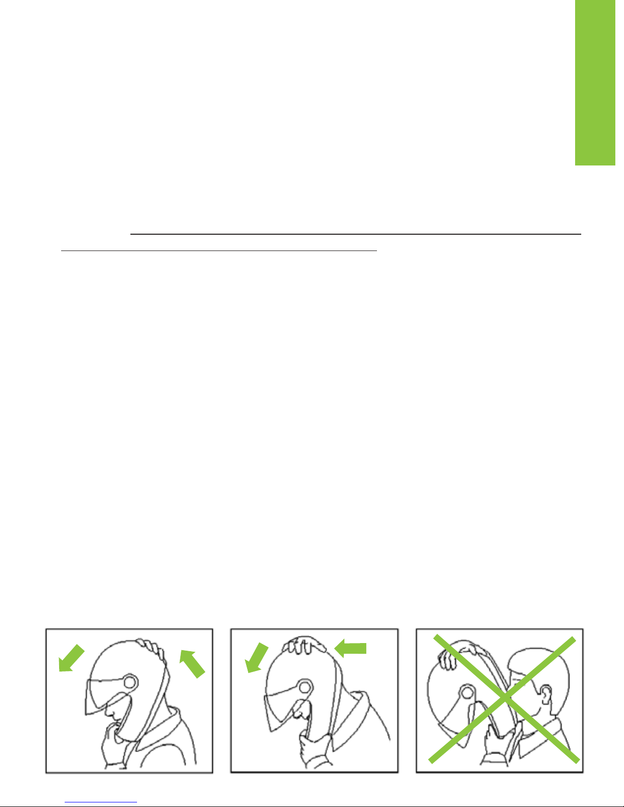
- The helmet should not rotate nor move on the head and should not slide off. Should
the contrary happen, adjust strap length or change helmet size. Repeat test.
Retention System:
- The retention system (strap) is factory-adjusted at a standard length. Before use,
check that it is correctly pre-adjusted.
- Make sure the strap is properly fastened and tightened so as to keep the helmet
firmly in place. Anyway, before riding, make sure that the strap is well fastened
under the chin, as close as possible to the throat, but without being uncomfortable.
- The correct strap tension should allow normal breathing and swallowing, but without
leaving the space of a finger between strap and throat.
- Attention: the button which may be present on the strap only prevents its end from
flapping once the strap has been fastened properly.
• VISOR:
- If the visor is damaged or deeply scratched causing reduced visibility, this means that
the protective treatment is probably damaged so the visor is to be replaced.
- Do not paint nor apply stickers.
- The visor can be used only for the intended helmet model.
• MAINTENANCE AND CLEANING
- Damage resulting from accidental fall may not be visible; helmets, which received
violent impacts, are to be replaced.
- Attention: Helmet and visor may be seriously damaged by some common substances
without the damage being however visible. Use only lukewarm water and mild soap to
clean helmet and visor, and then let them dry at room temperature away from sunrays
and/or heat sources.
- Attention: Never use petrol, thinner, benzene, solvents nor other chemicals which
may:
• Irreparably damage the helmet
• Modify optical properties, reduce mechanical ones and weaken the visor protective
treatment.
Fig. A
13
ENGLISH

INSTRUCTIONS FOR USE
The X-1003 helmet can be used in two configurations (chin guard closed - P / chin guard
open - J). The use of the helmet in configuration P (with chin guard and visor closed) obviously offers the highest degree of protection in comparison to configuration J (with chin guard
and visor open).
• CHIN GUARD OPENING SYSTEM
The X-1003 is equipped with the unique “Dual Action” chin guard opening system.
Positioned in the centre of the chin guard, it allows for easy, one-handed opening and prevents it from accidentally opening because the chin guard can be opened by operating the
second release lever only when the first lever has already been released.
N.B.: For an easier fitment of the helmet we may suggest you to keep the chinguard
opened and the vps in the up position during the operation.
1 OPENING
1.1. Push the red release lever outwards by turning it with your thumb (Fig. 1).
1.2 Place your forefinger on top of the opening lever and push it downwards so as to unlock
the chin guard (Fig. 2).
1.3 Pull the flip-up chin guard forwards, accompanying it as it rotates upwards with an ellip-
tical movement (Fig. 3).
WARNING: If the helmet is used in configuration J (with chin guard open), it is recom-
mended to place the left side locking slider in position “J” (see instructions for P/J configuration - Fig. 5, slider upwards) to secure the chin guard in lifted position.
2 CLOSING
WARNING:
In order to be able to close the chin guard, make sure the side locking sli-
der is in position “P”, as shown in fig. 4 (slider downwards).
2.1 Pull the chin guard downwards, accompanying it as it rotates, until you hear the clicks
of the closing mechanism.
2.2 Make sure that the chin guard is properly fastened.
• P/J CONFIGURATION
Fig. 4 (slider forward)
When the side locking slider is in position “P” (Fig. 4, slider downwards) the chin guard can
be opened and/or closed.
Fig. 5 (slider upwards)
When the side locking slider is in position “J” (Fig. 5, slider upwards), the chin guard cannot
be closed, remaining locked in open position.
WARNING! In this configuration, the chin guard cannot be closed again.
Do not force the closing of the chin guard because it could cause damages in the helmet’s closing mechanism. To close the chin guard, it is necessary to move the locking
slider to position P (Fig. 4, slider downwards).
WARNING!!!
- The protection level of this helmet whilst riding depends upon the configuration adop-
ted by the user: total protection if the chin guard and visor are closed, partial protection
if the chin guard and/or visor are open.
- Do not remove nor tamper with the fixing screws that connect the chin guard to the
shell.
14

15
- Do not use the helmet without the chin guard.
- Do not use the helmet in case of faulty chin guard. Contact immediately a X-LITE autho-
rized dealer.
• SCRATCH RESISTANT VISOR: VISOR WITH SCRATCH RESISTANT
UNIFORM THICKNESS
1 DISASSEMBLY (Fig. 6)
1.1 Close the chin guard and set the visor in open position.
1.2 Press and hold the visor release button (A) down and slide the visor forwards until it
clicks.
1.3 Free the visor fastenings (B1 and B2) from their seats.
1.4 Repeat the same steps on the other side of the helmet.
2 ASSEMBLY (Fig. 7)
2.1 Close the chin guard and set the visor in open position by placing the visor fastenings
(B1 and B2) in line with the housings in the visor mechanism.
2.2 Insert fastening B1 in the provided seat and press the visor against the shell in line with
fastening B2. This will activate the visor release button.
2.3 Slide the visor until it locks into place.
2.4 Repeat the same steps on the other side of the helmet.
WARNING!!!
- Make sure that the system is working properly. Open the visor; while lifting the chin
guard, the visor should automatically close.
- Do not use the helmet if the visor has not been assembled properly.
- If the visor opening/closing mechanisms are not working properly or if such mecha-
nisms get damaged, please contact a X-LITE authorized dealer.
• DOUBLE ACTION
In the neutral (central) position, as illustrated in figure 8, the Double Action button has no
effect on the normal opening and closing functions of the visor. The following additional functions are obtained using the button:
Defogging Function
While wearing the helmet, open the visor onto the first notch and press the Double Action
button as shown in Fig. 9. Now close the visor.
In this position, the mechanism keeps the visor open to a minimum to improve the circulation of air and facilitate defogging, especially at low speeds or during short stops.
To deactivate Double Action, press the button as shown in Fig. 10 to bring it back to the neutral position.
Visor-Lock Function:
While wearing the helmet, close the visor and press the Double Action button as shown in
Fig. 10.
In this position, the closing mechanism on the visor is strengthened so that it will not open
accidentally, even at high speeds.
To deactivate the visor lock, press the button as shown in Fig. 9 to bring it back to the neutral position.
®

Warning! When using the helmet, it is recommended that you limit your use of the visor-lock
function, since unexpected events may require you to open your visor immediately.
Warning! In the event of an emergency, the Double Action visor lock may be disabled by lifting the visor as normal, and pressing slightly harder than usual on the visor flap.
•
(Available as an optional accessory)
1 PINLOCK®INNER VISOR ASSEMBLY
1.1 Remove the visor.
1.2 Make sure that the inner surface of the visor is clean and check that the pin adjustment
external levers are turned inwards.
1.3 Place the Pinlock
®
inner visor on the visor. WARNING: The silicone-sealed profile of the
Pinlock
®
inner visor should be in contact with the inner surface of the visor.
1.4 Fasten one side of the Pinlock
®
inner visor to one of the visor pins and hold it in posi-
tion (Fig. 11).
1.5 Widen the visor and fasten the other side of the Pinlock
®
inner visor to the second pin
(Fig. 12).
1.6 Release the visor.
1.7 Remove the protective film from the Pinlock
®
inner visor and check that the entire silico-
ne-sealed profile of the inner visor adheres to the visor.
1.8 Fit the visor in the helmet.
CHECKING AND ADJUSTING THE INNER VISOR STRETCHING
Check the correct system assembly by opening and closing the visor. Check that both visors
are correctly fastened and do not move.
If the inner visor is not tightly fixed to the visor, move the external adjustment levers simultaneously upwards to increase the stretch (Fig. 13). This operation must be carried out gradually.
The maximum stretch is achieved when the pin adjustment external levers are turned outwards.
WARNING!!!
The presence of dust between the two visors may produce scratches on both surfaces.
Scratched visors and inner visors may cause reduced visibility and must therefore be
replaced.
Regularly check the correct stretching of the inner visor to prevent the same from moving and
scratching both surfaces.
If the helmet visor fogs up and/or condensation forms between the visors, check both for
system correct assembly and stretching.
An excessive and early stretch of the inner visor may result in excessive adherence against
visor surface and/or permanent deformations with subsequent inability to perform following
adjustments correctly.
The extended use under special weather conditions may reduce system performance and
result in partial fogging and problems of condensation on the inner visor. In this case, remove the inner visor from the helmet visor and dry it with dry and lukewarm air to restore system
efficiency.
Intense sweating /breathing, the use under particular weather conditions (low temperatures,
and/or high humidity and/or sudden changes in temperature or heavy rain) and intense and
prolonged use may affect the performance of the system and cause the fogging or formation
of condensation on the inner visor.
16

17
In such cases, after using the helmet and to restore the system efficiency, remove the inner
visor from the helmet visor and let it dry with dry and lukewarm air. The same procedure must
be applied to the helmet, in order to dry out humidity in case it has formed up as a consequence of the conditions described above.
2 PINLOCK®INNER VISOR DISASSEMBLY
2.1 Remove the visor equipped with the Pinlock®inner visor.
2.2 Widen the visor and release the Pinlock
®
inner visor from the pins (Fig. 12).
2.3 Release the visor.
MAINTENANCE AND CLEANING
Remove the Pinlock®inner visor from the visor. Using a damp and soft cloth, gently clean it
with neutral liquid soap. Remove the soap under running water.
Dry the inner visor with dry and lukewarm air without wiping it.
To keep the features of the inner visor in good conditions over time, let the helmet dry in a
ventilated and dry place with the visor open after use.
Keep it away from heat sources and store it in a place away from direct light.
• VISION PROTECTION SYSTEM (VPS)
The new and exclusive inner Vision Protection System (VPS) is a - moulded sun screen with scratch-resistant and fog-resistant treatment.
Using it is very simple and practical: Just lower it to activate it or lift it to remove it from the
field of vision. It is useful in all sorts of situations, both on long journeys out of town and shorter town trips. Moreover, the fastening system allows you to assemble and disassemble the
sun screen without any tools to allow ordinary maintenance and cleaning operations.
VPS OPERATION
The VPS mechanism allows activating the sun screen by simply lowering it until it partially covers the visor field of vision. In this way, the desired light transmittance reduction is
achieved.
At any time, without operating the visor, the VPS can be deactivated with a simple movement
and easily pulled up to restore the normal conditions of visibility and protection guaranteed
by the approved helmet visor. To deactivate the VPS, push the slider downwards (Fig. 14)
until you hear the click which means the slider and VPS are correctly in place. To activate the
VPS, push the slider upwards (Fig. 15). The VPS has been designed to ensure an easy, quick
and tool-free disassembly.
PRECAUTIONS FOR USE
The current approval standards (ECE22-05) state that the visor minimum light transmittance
levels must be greater than 80% when riding at night and not less than 50% when riding
during the day. For this reason, when riding during the day under particularly bright weather
conditions, e.g. very strong sunlight caused by high intensity and/or incidence of the sunbeams, the use of sunglasses - which entail a transmittance much lower than 50% - turns out
to be advisable, if not absolutely necessary, to reduce eye fatigue on long trips. Sunglasses
also reduce the risk of direct dazzling as opposed to the use of mere approved visors.
However, the use of sunglasses makes it difficult to perform emergency manoeuvres when
the maximum visibility range of the visor must be quickly restored. Just think, for example, of
what happens when you enter a tunnel or when unexpected changes in environmental brightness occur.
Thanks to its operating mechanism, the VPS makes these operations much easier.
®

WARNING!!!
- Use the special slider to activate/deactivate the VPS; do not deactivate the VPS by han-
dling it directly.
- The VPS can be activated only during the day and under the environmental conditions
described before.
- At night and/or in poor visibility conditions, the VPS MUST be deactivated.
- Always check that the VPS is properly positioned according to the different
weather/environmental conditions and/or to the above mentioned recommendations for
use.
- We recommend using the VPS only and solely together with the approved standard
visor, which has a transmittance value greater than 80%.
- Since the VPS does not assure you the same protection as the one provided by the
visor, it has to be used only when the helmet visor is pulled down.
- Always make sure that the VPS is clean and that it is operating properly in order to avoid
scratches and/or anomalous wear on it every time it is activated.
- ALWAYS check the correct VPS operation. In case of malfunctioning do not use the hel-
met and contact a X-lite authorized dealer immediately.
- Please refer to the proper section in the helmet user’s manual for the VPS and visor
maintenance and cleaning operations.
- The VPS scratch-resistant and fog-resistant treatment highly reduces fogging.
Protracted periods of adverse weather and/or environmental conditions might cause
fogging and/or formation of condensation on the VPS, which entails a reduction of visibility and/or sharpness of vision: in this case, deactivate the VPS.
- In case of rain, the direct contact of raindrops with the scratch-resistant and fog-resi-
stant treated VPS quickly reduces sharpness of vision, thus causing scarce visibility: in
this case, deactivate the VPS.
- The special VPS fog-resistant treatment is usually sensitive to high temperatures or heat
sources. In this case, contaminations caused by contact with other materials might
occur. These contaminations will cause marks and stains to develop. In these cases
(e.g. when the helmet is kept in the top case on hot days), it is recommended to make
sure the visor is not touching other materials.
1 VPS DISASSEMBLY INSTRUCTIONS
1.1 To disassemble the VPS, open the helmet visor and make sure the side slider is in dow-
nward position (Fig. 14).
1.2 Hold the left part of the VPS and pull it outwards until the grip pawl is removed from the
VPS mechanism (Fig. 16).
1.3 Repeat the same steps on the right side of the VPS and remove it.
2 VPS ASSEMBLY INSTRUCTIONS
2.1 To assemble the VPS, open the helmet visor and make sure the side slider is in upward
position (Fig. 14).
2.2 Insert the left end of the VPS into the left side guide until the grip pawl is hooked in the
mechanism (Fig. 16).
2.3 Repeat the same steps on the right side.
2.4 Check the correct VPS operation by moving the left side slider downwards (Fig. 15) and
upwards (Fig. 14) until you hear the clicks meaning that it is in the relevant positions.
If necessary, repeat the above-mentioned steps.
18

- If the visor and/or VPS opening/closing mechanisms are damaged or malfunctioning,
please contact an X-lite authorized dealer.
- Do not use the helmet if the VPS has not been assembled properly.
WARNING!!!
The VPS does not replace the protection guaranteed by the visor.
• WIND PROTECTOR
This accessory allows improved helmet performance under certain conditions of use.
The Wind Protector reduces unpleasant infiltrations of air under the chin.
See Fig. 17 for the assembly and disassembly.
WARNING!!!
The Wind Protector can be easily removed. You can check the correct assembly of this
accessory by pulling it gently towards the inner part of the helmet with your thumb and
forefinger. If it moves, repeat the assembling operations.
• ROLL NECK
1 DISASSEMBLY
1.1 Undo the chin strap.
1.2 Pull out the chin strap ends from the loops in the roll neck (Fig. 18).
1.3 Release the button on the back of the left cheek pad (Fig.21), release the roll neck eye-
let fastener (Fig. 19) and hook the cheek pad again. Repeat the same operation for the
right cheek pad.
1.4 Open the zip and remove the roll neck (Fig. 20).
1.5 After removing the roll neck, it is necessary to check that the chin strap is adjusted cor-
rectly (see attached label).
2 ASSEMBLY
2.1 Undo the chin strap.
2.2 Insert the roll neck, fasten it and close the zip.
2.3 Insert both ends of the chin strap in the specific loops on the roll neck (Fig. 18).
2.4 Release the button on the back of the left cheek pad (Fig. 21), hook the roll neck eyelet
fastener (Fig. 19) and hook the cheek pad again. Repeat the same operation for the right
cheek pad.
2.5 Before using the helmet, make sure that the sliding clip of the zip does not protrude from
the helmet itself and that it is correctly bent and folded between the roll neck padding
and the chin strap.
2.6 After assembling the roll neck, it is necessary to check that it is adjusted correctly.
• TOURING PERFORMANCE COMFORT - INNER COMFORT PADDING
To remove and/or reassemble the inner comfort padding, open the helmet chin guard and lift
the VPS (Fig. 15).
1 DISASSEMBLY OF THE CHEEK PADS
1.1 Open the chin strap (see specific instructions) and pull the front part of the left cheek
pad towards the inside of the helmet to release the snap fasteners on the rear of the pad
(Fig. 21).
1.2 Remove the padding of the left cheek pad from the helmet by pulling the left chin strap
out of the cheek pad slot.
1.3 Repeat these steps with the padding of the right cheek pad.
19

2 DISASSEMBLY OF THE LINER
2.1 Hold the central part of the back rest and pull it towards the inside of the helmet to
remove it.
Release the buttons from their respective left and right fastening seats (Fig. 22).
2.2 Hold the central area of the liner and pull it towards the inside of the helmet in order to
slide out the central flap located between the polystyrene and the shell, then unhook the
left and right side flaps from their fastening seats. (Fig. 23).
2.3 Completely remove the liner from the helmet.
3 ASSEMBLY OF THE LINER
3.1 Insert the liner into the shell of the helmet and fit it symmetrically well against the base.
3.2 Check that the flap in the front area and the side fastening flaps match up and, once you
have verified the whole assembly, first fasten the left and right side flaps to their fastening seats, then insert the central flaps between the polystyrene and the shell (Fig. 23).
3.3 Repeat the same operation from point 3.2 for the liner’s back rest (Fig. 22).
3.4 Carefully adjust the liner until it adheres well to the shell.
NOTE: Do not remove the polystyrene cheek pads.
NOTE: Check the correct assembly of the liner front area by lifting and lowering the
VPS. These movements should be smooth. If this is not the case, repeat the steps 2.2
and 3.2.
4 ASSEMBLY OF THE CHEEK PADS
4.1 Insert the band and the left chin strap into the slot of the left cheek pad.
4.2 Push the padding of the cheek pad in line with the snap fasteners on its back in order
to fasten them to their seats (Fig. 21).
4.3 Repeat these steps with the padding of the right cheek pad.
WARNING!!!
- Remove the padding only when cleaning or washing is required.
- Never use the helmet if the inner comfort padding and the cheek pads have not been
correctly and completely reassembled.
- Delicately hand-wash in lukewarm water (max. 30°C) and neutral soap.
- Rinse off with cold water and dry at room temperature away from direct sunlight.
- Never machine-wash the inner comfort padding.
- The inner polystyrene is an easily deformable material, in fact it is apt to change or get
partially destroyed to help absorb shocks.
- Use a damp cloth to clean it and let it dry at room temperature away from direct
sunlight.
- Do not modify the helmet’s internal polystyrene components in any way.
- Never use tools or equipment of any sort to carry out the steps described above.
• EYEWEAR ADAPTIVE
The new and exclusive Eyewear Adaptive (EA) is designed for the comfort of eyeglass wearers. In a quick and easy way, EA allows us to obtain a space in the cheek pads for the glasses temples.
The system is reversible, so the cheek pads can be returned to the initial configuration.
To enjoy the comfort of the helmet with glasses:
20

1. Remove the cheek pads from the helmet (please refer to paragraph “removable inner
comfort padding”, section “removal”).
2. Open the LEFT cheek pad (Fig. 24), remove the inner padding at the top and remove
the die cut part.
Note: we advise you to keep this part of the removed padding for any subsequent
reuse.
3. Reinsert the inner padding correctly and close the cheek pad.
4. Repeat steps 2 and 3 on the RIGHT cheek pad.
5. Replace the cheek pads on the helmet (please refer to paragraph “TOURING PERFOR-
MANCE COMFORT”, section “assembly”).
To restore the initial conditions:
1. Remove the cheek pads from the helmet (please refer to paragraph “TOURING PER-
FORMANCE COMFORT”, section “removal”).
2. Open the LEFT cheek pad (Fig. 25), and insert the die cut padding, which had previou-
sly been removed, at the top of it.
3. Reinsert the inner padding correctly and close the cheek pad.
4. Repeat steps 2 and 3 on the RIGHT cheek pad.
5. Replace the cheek pads on the helmet (please refer to paragraph “removable inner
comfort padding”, section “assembly”).
• VENTILATION SYSTEM
FRONT AND TOP VENTILATION SYSTEM (Fig. 26 and Fig. 27)
The front air intakes allow conveying air into the shell. Maximum efficiency is reached when
the VPS is active (lowered):
A) Closed
B) Open
REAR EXTRACTOR (Fig. 28)
The rear extractor ensures optimal heat dissipation.
FRONT PART VENTILATION SYSTEM (Fig. 29)
The open ventilation system allows conveying air directly to the visor, to reduce visor fogging
and formation of condensation:
A) Closed
B) Open
BODY SIDE EXTRACTORS (Fig. 30)
The side air extractor system facilitates the dissipation of hot air.
21

WIR GRATULIEREN... zum Erwerb Ihres neuen Helms.
Das Design, die Ergonomie, der Komfort, die Windschnittigkeit, die einfache und zweckmäßige Bedienung; all dies wurde geplant und realisiert, um ein modernes und extrem leistungsfähiges Produkt zu erhalten, das in der Lage ist, Ihre Sicherheits- und
Komfortbedürfnisse zu erfüllen.
SICHERHEIT UND GEBRAUCHSVORSCHRIFTEN
• WICHTIG!
- Lesen sie dieses Heft und alle anderen beigefügten Unterlagen vor Verwendung
Ihres Helms, da sie wichtige Informationen enthalten, die Ihnen helfen, den Helm
richtig, sicher und einfach zu verwenden.
- Wenn Sie sich nicht an diese Anweisungen halten, könnte der vom Helm gebotene
Schutz sich verringern, und somit Ihre Unversehrtheit nicht mehr gewährleistet sein.
• VERWENDUNG DES HELMS
- Der Helm wurde speziell für die Verwendung beim Lenken von Motorrädern und
Motorfahrrädern entworfen; daher garantiert er nicht denselben Schutz, wenn er
anderweitig eingesetzt wird.
- Im Fall eines Unfalls ist der Helm ein Schutzgerät, das es ermöglicht, Kopfverletzungen
und –schäden zu begrenzen. Trotzdem ist er nicht allein in der Lage, das Risiko schwerer und/oder tödlicher Verletzungen auszuschließen, welche von den unterschiedlichen
spezifischen Verlaufsweisen des Aufpralls abhängen; fahren Sie daher vorsichtig.
- Setzen Sie beim Motorradfahren immer Ihren gut festgezogenen Helm auf, um den
größtmöglichen Schutz zu erhalten.
- Niemals einen Schal unter dem Verschlusssystem und keine Kopfbedeckungen unter
dem Helm tragen.
- Der Helm kann die Verkehrsgeräusche abdämpfen. Versichern Sie sich in jedem Fall,
dass Sie die nötigen Geräusche wie Hupen und Notsirenen gut hören.
- Bewahren Sie den Helm fern von Wärmequellen auf, wie zum Beispiel dem
Auspuffrohr, dem Kofferraum oder dem Innenraum eines Verkehrsmittels.
- Verändern und/oder beschädigen Sie den Helm in keinem Fall (auch nicht teilweise).
Montieren Sie nur Originalersatzteile und/oder –zubehörteile die eigens für Ihr
Helmmodell vorgesehen sind.
- Beschädigungen des Helms, die durch ein versehentliches Fallen verursacht werden
können, sind nicht immer sichtbar; jeder Helm, der einem heftigen Stoß erfahren hat,
muss ersetzt werden.
- Sollten Sie über die Unversehrtheit und Sicherheit Ihres Helms im Zweifel sein, benutzen Sie ihn nicht und wenden Sie sich an einen autorisierten Fachhändler, um ihn
untersuchen zu lassen.
• HELMWAHL
Größe:
- Um die richtige Größe zu ermitteln, setzen Sie Helme unterschiedlicher Ausmaße auf
und wählen Sie den, der fest aber völlig bequem anliegt.
- Ein zu großer Helm kann über die Augen herabsinken oder während der Fahrt seitlich
verrutschen.
- Behalten Sie ihn einige Minuten lang auf, um zu verifizieren, dass keine Druckstellen
bestehen, die auf längere Zeit Gefühllosigkeit oder Kopfschmerzen verursachen können.
22
Abstreifen des Helms:
- Versuchen Sie den aufgesetzten und festgeschnallten Helm wie in der Abbildung
(Abb. A) gezeigt abzustreifen. Bei einem Unfall tendieren die aus unterschiedlichen
Richtungen kommenden Stöße nämlich dazu, den Helm vom Kopf zu streifen.
- Der Helm darf sich weder drehen, noch sich frei um den Kopf herum bewegen oder
abstreifen lassen. In entgegengesetztem Fall regulieren Sie die Kinnriemenlänge
oder wählen Sie eine andere Helmgröße. Wiederholen Sie den Test.
Rückhaltesystem:
- Das Rückhaltesystem (Kinnriemen) ist in Serie auf eine Standardlänge eingestellt;
vor der Verwendung kontrollieren Sie die richtige Vor-Einstellung.
- Versichern Sie sich immer, dass der Kinnriemen gut verschlossen und festgezogen ist,
damit der Helm fest auf dem Kopf sitzt. Versichern Sie sich in jedem Fall vor der
Abfahrt, dass der Kinnriemen unter dem Kinn eng anliegt, so weit wie möglich in
Richtung des Halses, aber ohne unbequem zu sein.
- Die richtige Kinnriemenspannung muss ihnen ein normales Atmen und Schlucken
erlauben, es darf aber nicht möglich sein, einen Finger zwischen Riemen und Hals zu stecken.
- Achtung: der Knopf, welcher sich am Ende des Kinnriemens befindet, hat ausschließlich
die Funktion, das Flattern des Endstücks zu verhindern, nachdem er korrekt festgeschnallt worden ist.
• VISIER
- Ist das Visier beschädigt und weist es deutliche Kratzer auf, welche die Sicht behindern, ist es möglich, dass die Schutzbehandlung lädiert wurde; in diesem Fall muss
das Visier ersetzt werden.
- Bringen Sie keine Aufkleber oder Lackfarben an.
- Das Visier ist ausschließlich für das Helmmodell, für das es entworfen wurde, verwendbar.
• INSTANDHALTUNG UND REINIGUNG
- Beschädigungen des Helms, die durch ein versehentliches Fallen verursacht werden
können, sind nicht immer sichtbar; jeder Helm, der einem heftigen Stoß erfahren hat,
muss ersetzt werden.
- Achtung: Der Helm und das Visier können durch einige übliche chemische Substanzen
ernsthaft beschädigt werden, ohne dass der Schaden sichtbar ist. Für die Reinigung
des Helms und des Visiers nur lauwarmes Wasser und Neutralseife verwenden; bei
Raumtemperatur im Schatten und fern von Wärmequellen trocknen lassen.
- Achtung: Keinesfalls Benzin, Verdünnungsmittel, Benzol, Lösungsmittel oder andere
chemische Substanzen verwenden. Diese können:
• den Helm unwiederbringlich beschädigen;
• die optischen Eigenschaften verändern, die mechanischen Eigenschaften verringern
und die Schutzbehandlung des Visiers schwächen.
Abb. A
23
DEUTSCH

GEBRAUCHSANLEITUNG
Der Helm X-1003 kann in zwei Konfigurationen verwendet werden (mit geschlossenem Kinnteil P / mit offenem Kinnteil - J). Die Verwendung des Helms in der Konfiguration P (mit geschlossenem Kinnteil und Visier) bietet naturlich einen besseren Schutz als die Konfiguration J (mit offenem
Kinnteil und Visier).
• ÖFFNUNGSMECHANISMUS DES KINNTEILS
Der Helm X-1003 ist mit dem exklusiven Öffnungssystem fur das Kinnteil “Dual Action” ausgestat-
tet, das sich in der Mitte des Kinnteils befindet und die Öffnung mit nur einer Hand ermöglicht.
Daruber hinaus kann die versehentliche Öffnung vermieden werden: erst nachdem der erste
Entriegelungshebel betätigt wurde, kann das Kinnteil uber den zweiten Hebel geöffnet werden.
Hinweis: Zum Auf- und Absetzen des Helmes das Kinnteil aufklappen und die
Sonnenblende (VPS) in die obere Position bringen.
1 ÖFFNUNG
1.1 Den roten Entriegelungshebel nach außen drücken, indem er mit dem Daumen gedreht wird
(Abb. 1).
1.2 Den Zeigefinger auf den Öffnungshebel legen und diesen nach unten drücken, um das
Kinnteil zu entriegeln (Abb. 2).
1.3 Das aufklappbare Kinnteil nach vorne ziehen und die Drehbewegung nach oben mit den
Händen führen (Abb. 3).
ACHTUNG: Wenn der Helm in der Konfiguration J (mit offenem Kinnteil) verwendet wird,
wird empfohlen, den seitlichen Sperrschieber links in die Position “J” zu schieben (siehe
Anleitung Konfiguration P/J - Abb. 5, Schieber oben), damit das Kinnteil hochgeklappt
bleibt.
2 SCHLIESSUNG
ACHTUNG:
Für die Schließung des Kinnteils wird überprüft, ob der seitliche Sperrschieber
sich in Position P befindet, wie in Abb. 4 (Schieber unten) gezeigt.
2.1 Das Kinnteil nach unten ziehen und die Drehbewegung dabei begleiten, bis das Einrasten
des Schließmechanismus zu hören ist.
2.2 Sicherstellen, dass das Kinnteil korrekt eingerastet ist.
• KONFIGURATION P/J
Abb. 4 (Schieber vorne)
Wenn sich der seitliche Sperrschieber in der Position “P” (Abb. 4, Schieber unten) befindet, kann
das Kinnteil geöffnet und/oder geschlossen werden.
Abb. 5 (Schieber oben)
Wenn sich der seitliche Sperrschieber in der Position “J” (Abb. 5, Schieber oben) befindet, kann
das Kinnteil nicht geschlossen werden und bleibt in der geöffneten Position gesperrt.
ACHTUNG! In dieser Konfiguration kann das Kinnteil nicht wieder herunter geklappt wer-
den. Es darf nicht gewaltsam geschlossen werden, da dies zu Schäden an der
Schließmechanik des Helms führen könnte. Um das Kinnteil zu schließen, muss der
Sperrschieber in die Position P (Abb. 4, Schieber unten) gebracht werden.
ACHTUNG!!!
- Das Schutzniveau dieses Helms während der Fahrt mit dem Fahrzeug hängt von der vom
Benutzer gewählten Konfiguration ab: kompletter Schutz mit geschlossenem Kinnteil und
Visier, Teilschutz mit offenem Kinnteil und/oder Visier.
- Die Schrauben, mit denen das Kinnteil an der Helmschale befestigt ist, durfen nicht entfernt
und/oder verändert werden.
24

25
- Der Helm darf ohne Kinnteil nicht benutzt werden.
- Im Falle von Defekten des Kinnteils darf der Helm nicht benutzt werden. Wenden Sie sich
unverzuglich an einen X-LITE-Händler.
• SCRATCH RESISTANT VISOR: VISIER MIT KRATZFEST BESCHICHTETEM
1 ABNAHME (Abb. 6)
Das Kinnteil schließen und das Visier vollständig in die Position Offen schieben.
1.2 Die Entriegelungstaste des Visiers (A) gedruckt halten und das Visier bis zum Auslösen nach
vorne schieben.
1.3 Die Visierhaken (B1 und B2) aus ihrer Vertiefung lösen.
1.4 Die beschriebenen Schritte auf der anderen Helmseite wiederholen.
2 MONTAGE (Abb. 7)
2.1 Das Kinnteil schließen, das Visier in geöffneter Stellung halten und die Visierhaken (B1 und
B2) an den in der Visiermechanik vorgesehenen Vertiefungen positionieren.
2.2 Den Haken B1 in die vorgesehene Vertiefung einfuhren und das Visier am Haken B2 gegen
die Schale drucken, um die Entriegelungstaste des Visiers auszulösen.
2.3 Das Visier so weit schieben, bis das Verschlusssystem einrastet.
2.4 Die beschriebenen Schritte auf der anderen Helmseite wiederholen.
ACHTUNG!
- Prüfen, ob das System richtig funktioniert. Das Visier öffnen. Wird das Kinnteil hochgeklappt,
muss sich das Visier automatisch schließen
- Den Helm keinesfalls benutzen, wenn das Visier nicht richtig angebracht ist.
- Sollte die Öffnungs- und Schließmechanik des Visiers Störungen oder Beschädigungen auf-
weisen, wenden Sie sich an einen X-LITE- Vertragshändler.
• DOUBLE ACTION
Befindet sich die Taste Double Action in neutraler Position (mittlere Position), wie in der Abbildung
8 gezeigt, so hat sie keinerlei Auswirkung auf die normalen Funktionen des Visiers in der Öffnung
und der Schließung. Mit dieser Taste können die folgenden Zusatzfunktionen genutzt werden:
Beschlagschutz
Bei aufgesetztem Helm wird das Visier geöffnet, bis ein erstes Einrasten zu hören ist, und die Taste
Double Action gemäß der Angaben in Abb. 9 gedruckt. Dann ist das Visier wieder zu schließen.
In dieser Position kann das Visier durch die Mechanik in einer Position der minimalen Öffnung
gehalten werden, die die Beluftung verbessert und das Beschlagen vor allem bei geringer
Geschwindigkeit oder bei kurzen Pausen verhindert.
Um die Funktion Double Action auszuschalten, wird die Taste gemäß der Angaben in Abb. 10
gedruckt und in die neutrale Position zuruckgefuhrt.
Funktion Visiersperre
Bei aufgesetztem Helm wird das Visier geschlossen und die Taste Double Action gemäß der
Angaben in Abb. 10 gedruckt. In dieser Position wird der Einrastmechanismus des Visiers fur die
Schließung verstärkt, damit auch bei hohen Geschwindigkeiten keine versehentliche Öffnung des
Visiers auftreten kann.
Um die Funktion der Visiersperre auszuschalten, wird die Taste gemäß der Angaben in Abb. 9
gedruckt und in die neutrale Position zuruckgefuhrt.
Achtung! Während der Benutzung des Visiers können unvorhergesehene Situationen eintreten,
die eine unverzugliche Öffnung des Visiers erfordern. Aus diesem Grunde wird empfohlen, die
Funktion der Visiersperre nur begrenzt einzusetzen.
®

Achtung! Im Notfall kann die Visiersperre Double Action ausgeschaltet werden, indem das Visier
auf die herkömmliche Art nach oben geschoben und etwas stärker auf die Lasche gedruckt wird,
als dies normalerweise erforderlich ist.
•
(Erhältlich als optionales Zubehör)
1 ANBRINGEN DES INNENVISIERS PINLOCK
®
1.1 Das Visier abnehmen.
1.2 Sicherstellen, dass die Innenfläche des Visiers sauber ist und dass die äußeren Einstellhebel
der Zapfen nach innen gerichtet sind.
1.3 Das Innenvisier Pinlock
®
auf das Visier auflegen. ACHTUNG: Das Silikonprofil des
Innenvisiers Pinlock
®
muss auf der Innenfläche des Visiers aufliegen.
1.4 Eine Seite des Innenvisiers Pinlock
®
in einen der beiden Zapfen des Visiers einstecken und
in dieser Position halten (Abb. 11).
1.5 Das Visier aufbiegen und die zweite Seite des Innenvisiers Pinlock
®
auf dem anderen Zapfen
aufstecken (Abb. 12).
1.6 Das Visier loslassen.
1.7 Die Schutzfolie vom Innenvisier Pinlock
®
abziehen und uberprufen, ob das gesamte
Silikonprofil des Innenvisiers auf dem Visier anliegt.
1.8 Das Visier auf dem Helm anbringen.
ÜBERPRÜFUNG UND EINSTELLUNG DER HAFTUNG DES INNENVISIERS
Durch Öffnen und Schließen des Visiers prufen, ob das System korrekt montiert wurde. Das Visier
und das Innenvisier durfen nicht gegeneinander verrutschen.
Sollte das Innenvisier nicht fest am Visier anliegen, die beiden äußeren Einstellhebel gleichzeitig
stufenweise und nicht zu stark nach oben drehen, um die Haftung zu verbessern (Abb. 13). Die
maximale Haftung wird erreicht, wenn die äußeren Einstellhebel der Zapfen nach außen gerichtet
sind.
ACHTUNG!!!
Das Vorhandensein von Staub zwischen dem Visier und dem Innenvisier kann Kratzer auf beiden
Oberflächen verursachen.
Durch Kratzer beschädigte Visiere und Innenvisiere können die Sicht beeinträchtigen und mussen
ausgetauscht werden.
Die Haftung des Innenvisiers regelmäßig kontrollieren, um zu vermeiden, dass es verrutscht und
dabei beide Flächen zerkratzt werden.
Sollte sich das Visier bei der Verwendung beschlagen und/oder bildet sich im Bereich zwischen
Visier und Innenvisier Kondenswasser, mussen die Montage und die Haftung des Systems uber-
pruft werden.
Wird das Innenvisier ubermaÅNssig stark und vorzeitig gegen die Visierfläche gedruckt, kann es
zu einer ubermaÅNssigen Haftung des Innenvisiers am Visier und/oder zu bleibenden
Verformungen kommen, und eine nachträgliche korrekte Einstellung ist nicht mehr möglich. Eine
längere Verwendung unter besonderen klimatischen Bedingungen kann die Wirksamkeit des
Systems beeinträchtigen und zu einem teilweisen Beschlagen bzw. zur Bildung von
Kondenswasser auf dem Innenvisier fuhren. Um in einem solchen Fall die Funktionstuchtigkeit des
Systems wiederherzustellen, muss das Innenvisier vom Helmvisier abgenommen und mit trockener, lauwarmer Luft getrocknet werden.
Durch starkes Schwitzen oder Atmen, die Benutzung unter besonderen klimatischen
Bedingungen (niedrige Temperaturen und/oder hohe Luftfeuchtigkeit und/oder plötzliche
Temperaturwechsel oder starker Regen) und die intensive und lange Benutzung kann die Effizienz
des Systems reduziert und ein Beschlagen oder die Bildung von Kondenswasser auf dem
Innenvisier verursacht werden.
26

Um in derartigen Situationen die Funktionstuchtigkeit des Systems nach der Benutzung wieder-
herzustellen, muss das Innenvisier vom Helmvisier abgenommen und mit trockener, lauwarmer
Luft getrocknet werden. In den oben beschriebenen Situationen sollte auch der Helm getrocknet
werden, um die eventuell im Inneren vorhandene Feuchtigkeit zu beseitigen.
2 ABNEHMEN DES INNENVISIERS PINLOCK
®
2.1 Das mit dem Innenvisier Pinlock®ausgestattete Visier abnehmen.
2.2 Das Visier aufbiegen und das Innenvisier Pinlock®von den Zapfen lösen (Abb. 12).
2.3 Das Visier loslassen.
INSTANDHALTUNG UND REINIGUNG
Das Innenvisier Pinlock®vom Visier abnehmen. Das Innenvisier mit einem feuchten weichen Tuch
vorsichtig mit flussiger neutraler Seife reinigen. Alle Seifenreste unter fließendem Wasser
abspulen.
Das Innenvisier mit trockener, lauwarmer Luft trocknen, ohne zu reiben.
Um die Eigenschaften des Innenvisiers langfristig zu erhalten, den Helm nach der Benutzung an
einem luftigen, trockenen Ort mit offenem Visier trocknen lassen.
Nicht in der Nähe von Wärmequellen oder an hellen Orten aufbewahren.
• VISION PROTECTION SYSTEM (VPS)
Das neue und exklusive Vision Protection System (VPS) besteht aus einem Sonnenschutz
aus mit scratchresistant/ fog-resistant, der einfach und bequem zu benutzen ist: Er muss
bei Bedarf nur abgesenkt und anschließend wieder angehoben werden, um aus dem Gesichtsfeld
entfernt zu werden. Nutzlich in allen Fahrsituationen, auf langen außerstädtischen Strecken oder
auf Kurzstrecken in der Stadt.
Das innovative Verschlusssystem ermöglicht daruber hinaus die einfache Anbringung und
Abnahme des Sonnenschutzschildes fur die normalen Vorgänge zur Pflege und Reinigung ohne
Werkzeug.
FUNKTIONSPRINZIP DES VPS
Mit dem VPS-Mechanismus kann der Sonnenschutzschild mit einer einfachen Bewegung aktiviert bzw. nach unten gezogen werden, bis er teilweise das Gesichtsfeld des Visiers bedeckt,
und dann in gewunschter Weise die Lichtdurchlässigkeit reduziert. Das VPS kann jederzeit mit
einer einfachen Handbewegung und unabhängig vom Visier deaktiviert bzw. nach oben
geschoben werden, um die normalen Sichtbedingungen und den Schutz des zugelassenen
Helmvisiers wiederherzustellen. Um das VPS zu deaktivieren, den Schieber nach unten
drucken (Abb. 14), bis ein Einrasten zu hören ist. Der Schieber und das VPS befinden sich nun
in der richtigen Stellung. Um das VPS zu aktivieren, den Schieber nach oben drucken (Abb.
15). Das VPS wurde so entwickelt, dass es einfach und schnell und ohne die Verwendung von
Werkzeug vom Helm abgenommen werden kann.
VORSICHTSMASSNAHMEN BEIM GEBRAUCH
Die aktuellen Zulassungsstandards (ECE22-05) legen fest, dass das Mindestniveau der
Lichtdurchlässigkeit von Visieren bei Fahrten während der Nacht mehr als 80% betragen muss
und bei Fahrten tagsuber nicht weniger als 50% betragen darf. Dadurch mussen häufig oder gar
immer Sonnenbrillen benutzt werden, durch die die Lichtdurchlässigkeit während Fahrten bei
Tageslicht mit Wetter- und Umgebungsbedingungen mit speziellem Licht, beispielsweise bei starker Helligkeit durch eine hohe Intensität und/oder einen ungunstigen Einfallswinkel der
Sonnenstrahlen, auf einen Wert weit unter 50 % reduziert wird, um die Ermudung der Augen bei
langen Strecken oder die Gefahr der direkten Blendung gegenuber dem alleinigen Einsatz der
zugelassenen Visiere zu vermindern. Die Verwendung von Sonnenbrillen kann jedoch zu besonders problematischen Situationen fuhren, wenn die maximale Lichtdurchlässigkeit des Helmvisiers
®
27

schnell wieder hergestellt werden muss, weil man z.B. in einen Tunnel einfährt, oder ganz allgemein, wenn sich die Helligkeit der Umgebung häufig ändert. Durch den Funktionsmechanismus
des VPS sind diese Vorgänge jedoch einfach umzusetzen.
ACHTUNG!!!
- Das VPS darf ausschließlich mit dem entsprechenden Schieber aktiviert oder deaktiviert wer-
den. Das VPS darf nicht durch direktes Anfassen deaktiviert werden.
- Das VPS darf nur bei Tageslicht und nur während der oben erwähnten
Witterungsbedingungen aktiviert werden.
- Das VPS MUSS während der Nacht und/oder bei schlechter Sicht hochgeklappt werden.
- Stets uberprufen, ob die Stellung des VPS den verschiedenen Witterungs-/
Umweltbedingungen und/oder den oben aufgefuhrten Gebrauchsempfehlungen angepasst ist.
- Die Verwendung des VPS wird ausschließlich gemeinsam mit dem zugelassenen serienmä-
ßigen Visier empfohlen, das uber einen Lichtdurchlässigkeitswert von mehr als 80% verfugt.
- Das VPS ersetzt nicht den Schutz, den das Visier bietet. Es darf deshalb nur mit abgesen-
ktem Helmvisier verwendet werden.
- UÅNberprufen, ob das VPS sauber und funktionstuchtig ist, damit bei der Absenkung des
VPS keine Kratzer und/oder ubermaÅNssiger Verschleiß desselben verursacht werden.
- Den korrekten Betrieb des VPS STETS uberprufen und den Helm bei Funktionsstörungen
nicht benutzen. In diesem Falle ist unverzuglich ein X-lite-Vertragshändler aufzusuchen.
- Durch die Behandlung scratch-resistant/fog-resistant des VPS wird die
Beschlagungsneigung beträchtlich reduziert. Liegen jedoch längerfristig schlechte
Wetterbedingungen oder kritische Umgebungsbedingungen vor, kann das VPS dennoch
beschlagen und/oder es bildet sich Kondenswasser, und die Sicht und/oder Sichtschärfe
werden reduziert: In diesem Falle muss das VPS deaktiviert werden.
- Bei Regen fuhrt der direkte Kontakt von Wassertropfen mit dem VPS mit Behandlung
scratch-resistant/fog-resistant zu einer schnellen Reduzierung der Sichtschärfe und damit
zur Beeinträchtigung der Gesamtsichtbedingungen: In diesem Falle muss das VPS deaktiviert werden.
- Die besondere fog-resistant des VPS ist im Allgemeinen empfindlich gegenuber hohen
Temperaturen oder Wärmequellen. In diesem Falle kann es im Kontakt mit anderen
Materialien zu Verunreinigungen, wie Streifen oder Flecken, kommen. Aus diesem Grunde
wird empfohlen, in solchen Situationen (wie bspw. an sehr heißen Tagen im Gepäckkoffer)
darauf zu achten, dass das Visier nicht mit anderen Materialien in Beruhrung kommt.
1 ANLEITUNG FÜR DIE ABNAHME DES VPS
1.1 Um das VPS abzunehmen, das Visier des Helms öffnen und sicherstellen, dass der seitliche
Schieber nach unten geschoben ist (Abb. 14).
1.2 Das VPS an der linken Seite anfassen und nach außen ziehen. Dabei den Befestigungszahn
vom Mechanismus des VPS lösen (Abb. 16).
1.3 Den selben Vorgang auf der rechten Seite des VPS wiederholen und dieses ganz abnehmen.
ANLEITUNG FÜR DIE MONTAGE DES VPS
2.1 Um das VPS zu montieren, das Visier des Helms öffnen und sicherstellen, dass der seitliche
Schieber nach oben geschoben ist (Abb. 14).
2.2 Das linke Ende des VPS in die seitliche linke Fuhrung einschieben, bis der Zahn in der
Vertiefung des Mechanismus einrastet (Abb. 16).
2.3 Den selben Vorgang auf der rechten Seite wiederholen.
2.4 UÅNberprufen, ob das VPS korrekt funktioniert, indem der seitliche linke Schieber nach
unten (Abb. 15) und nach oben (Abb. 14) geschoben wird, bis ein Einrasten in den jeweiligen
Positionen zu hören ist. Gegebenenfalls die oben beschriebenen Schritte wiederholen.
28

- Sollte die Öffnungs- und Schließmechanik des Visiers bzw. des VPS Störungen oder
Beschädigungen aufweisen, wenden Sie sich an einen X-lite-Vertragshändler.
- Den Helm nicht verwenden, wenn das VPS nicht korrekt montiert ist.
ACHTUNG!!!
Das VPS ersetzt nicht den vom Visier gebotenen Schutz.
• WIND PROTECTOR (WINDABWEISER)
Dieses Zubehör verbessert unter bestimmten Bedingungen die Eigenschaften des Helms.
Der Windabweiser (Wind Protector) reduziert ein unangenehmes Eindringen der Luft unter dem
Kinn. Siehe Abb. 17 fur die Anbringung und die Abnahme.
ACHTUNG!!!
Der Windabweiser ist leicht abnehmbar. Der richtige Sitz dieses Zubehörs wird uberpruft,
indem es sanft mit Daumen und Zeigefinger zur Helminnenseite gezogen wird.
Löst er sich dabei ab, muss die Montage wiederholt werden.
• NACKENPOLSTER
1 ABNAHME
1.1 Den Kinnriemen lösen.
1.2 Die beiden Endstücke des Kinnriemens aus den Durchgängen des Nackenpolsters herau-
sziehen (Abb. 18).
1.3 Den Knopf auf der Rückseite der linken Wangenpolsterung (Abb. 21) lösen, die
Befestigungsöse des Nackenpolsters (Abb. 19) lösen und die Wangenpolsterung wieder
anbringen. Den gleichen Vorgang für die rechte Wangenpolsterung wiederholen.
1.4 Den Reißverschluss öffnen und das Nackenpolster herausziehen (Abb. 20).
1.5 Nach der Herausnahme des Nackenpolsters muss die korrekte Einstellung des Kinnriemens
überprüft werden (siehe beigelegtes Infoblatt).
2 MONTAGE
2.1 Den Kinnriemen lösen.
2.2 Das Nackenpolster einlegen, den Reißverschluss einhängen und schließen.
2.3 Die beiden Endstücke des Kinnriemens in die entsprechenden Durchgänge des
Nackenpolsters einstecken (Abb. 18).
2.4 Den Knopf auf der Rückseite der linken Wangenpolsterung (Abb. 21) lösen und die
Befestigungsöse des Nackenpolsters (Abb. 19) anbringen. Danach die Wangenpolsterung
wieder anbringen. Den gleichen Vorgang für die rechte Wangenpolsterung wiederholen.
2.5 Vor der Benutzung des Helms sicherstellen, dass der Schieber des Reißverschlusses nicht
über den Helm übersteht und korrekt umgelegt wurde. Er sollte zwischen dem
Nackenpolster “Padding” und dem Band des Kinnriemens eingesteckt werden.
2.6 Nach dem Anbringen des Nackenpolsters muss die korrekte Einstellung überprüft werden.
• TOURING PERFORMANCE COMFORT - KOMFORTPOLSTERUNG
Zum Herausnehmen und/oder Einsetzen der Komfortpolsterung das Kinnteil des Helms öffnen
und das VPS hochklappen (Abb. 15).
1 HERAUSNEHMEN DER WANGENPOLSTERUNGEN
1.1 Den Kinnriemen öffnen (siehe entsprechende Anleitung), den vorderen Teil der linken
Wangenpolsterung in das Helminnere ziehen, dann die Befestigungsknöpfe auf der
Rückseite der Wangenpolsterung lösen (Abb. 21).
29

1.2 Die linke Wangenpolsterung aus dem Helm herausziehen, indem das linke Band des
Kinnriemens aus der Schlaufe in der Wangenpolsterung gezogen wird.
1.3 Die gleichen Vorgänge bei der rechten Wangenpolsterung wiederholen.
2 HERAUSNEHMEN DER POLSTERUNG
2.1 Das hintere Nackenpolster im mittleren Bereich fassen und ins Helminnere ziehen, bis es sich
löst
Die Knöpfe aus den jeweiligen Befestigungsaufnahmen links und rechts lösen (Abb. 22).
2.2 Die Polsterung im mittleren Bereich fassen und zur Innenseite des Helms ziehen, um die mit-
tlere Lasche, die zwischen dem Styropor und der Schale steckt, herauszuziehen.
Anschließend die rechte und linke Lasche aus den Befestigungsaufnahmen lösen (Abb. 23).
2.3 Die Polsterung vollständig aus dem Helm herausnehmen.
3 EINSETZEN DER POLSTERUNG
3.1 Die Polsterung symmetrisch in den Helm einlegen und richtig positionieren.
3.2 Kontrollieren, ob die Lasche des vorderen Bereichs und die seitlichen
Befestigungsaufnahmen übereinstimmen, und dann zuerst die linke und rechte Lasche in
ihren Aufnahmen befestigen und anschließend die mittleren Laschen zwischen dem Styropor
und der Schale einschieben (Abb. 23).
3.3 Den Schritt 3.2 beim hinteren Nackenpolster der Polsterung wiederholen (Abb. 22).
3.4 Die Polsterung anpassen und darauf achten, dass sie gut an der Innenschale anliegt.
HINWEIS: Die Wangenpolsterungen aus Polystyrol nicht entfernen.
HINWEIS: Die korrekte Montage des Frontbereichs der Polsterung überprüfen, indem das
VPS nach oben geschoben und abgesenkt wird: Diese Bewegung muss ohne Behinderung
möglich sein. Im gegenteiligen Fall sind die Schritte 2.2 und 3.2 zu wiederholen.
4 EINSETZEN DER WANGENPOLSTERUNGEN
4.1 Den Riemen und das linke Band des Kinnriemens durch die Schlaufe in der linken
Wangenpolsterung ziehen.
4.2 Die Wangenpolsterung andrücken, um die Befestigungsknöpfe auf der Rückseite an den vor-
gesehenen Stellen zu schließen (Abb. 21).
4.3 Die gleichen Vorgänge bei der rechten Wangenpolsterung wiederholen.
ACHTUNG!!!
- Die Polsterung sollte lediglich zum Reinigen oder Waschen entfernt werden.
- Den Helm keinesfalls benutzen, wenn die Komfortpolsterung und die Wangenpolsterungen
nicht wieder vollständig. und korrekt eingebaut wurden.
- Vorsichtig mit der Hand waschen, nur neutrale Seife benutzen, Wassertemperatur nicht
höher als 30° C.
- Die Polsterung mit kaltem Wasser spulen und vor Sonne geschutzt bei Zimmertemperatur
trocknen lassen.
- Die Komfortpolsterung keinesfalls in der Waschmaschine waschen.
- Beim fur die Innenteile verwendeten Polystyrol handelt es sich um ein leicht deformierbares
Material, das Stöße uber die Formveränderung oder die teilweise Zerstörung absorbiert.
- Fur die Reinigung ausschließlich ein feuchtes Tuch benutzen, dann bei Raumtemperatur und
vor Sonne geschutzt trocknen lassen.
- Die Innenteile aus Polystyrol nicht verändern oder beschädigen.
- Die oben aufgefuhrten Schritte mussen ohne den Einsatz von Werkzeugen ausgefuhrt
werden.
30

• EYEWEAR ADAPTIVE
Der neue und exklusive Eyewear Adaptive (EA) Helm garantiert jenen Komfort, auf den
Brillenträger immer schon gewartet haben. Auf einfache und schnelle Art und Weise kann in der
Wangenpolsterung der fu r die Brillenbugel notwendige Raum geschaffen werden.
Das System ist reversibel, d.h. die Wangenpolsterungen können wieder in den Ursprungszustand
zuruckgesetzt werden. Damit auch fur Brillenträger der größte Tragekomfort gewährleistet werden
kann, geht man folgendermaßen vor:
1. Die Wangenpolsterungen aus dem Helm herausnehmen (siehe Absatz “TOURING PERFOR-
MANCE COMFORT” Abschnitt “Abnahme”).
2. Linke Wangenpolsterung öffnen (Abb. 24), den im oberen Teil vorhandenen Innenpolster
herausnehmen und das gestanzte Teil entfernen.
Hinweis: Es wird empfohlen, den entfernten Teil der Polsterung fur eventuelle spätere
Wiedereinsätze aufzubewahren.
3. Die Innenpolsterung wieder in die Wangenpolsterung einsetzen und diese schließen.
4. Die Vorgänge von Punkt 2 und 3 auch auf der rechten Wangenpolsterung durchfuhren.
5. Die Wangenpolsterung wieder in den Helm einsetzen (siehe Absatz “TOURING PERFOR-
MANCE COMFORT”, Abschnitt “Montage”).
Um den Ursprungszustand wiederherzustellen, geht man folgendermaßen vor:
1. Die Wangenpolsterungen aus dem Helm herausnehmen (siehe Absatz “Herausnehmbare
innere Komfortpolsterung”, Abschnitt “Abnahme”).
2. Linke Wangenpolsterung öffnen (Abb. 25) und das vorher entfernte, gestanzte Teil wieder im
oberen Helmteil einsetzen.
3. Die Innenpolsterung wieder vorschriftsgemäß in die Wangenpolsterung einsetzen und diese
schließen.
4. Die Vorgänge von Punkt 2 und 3 auch auf der rechten Wangenpolsterung durchfuhren.
5. Die Wangenpolsterung wieder in den Helm einsetzen (siehe Absatz “Herausnehmbare inne-
re Komfortpolsterung”, Abschnitt “Montage”).
• BELÜFTUNGSSYSTEM
VORDERES und OBERES BELÜFTUNGSSYSTEM (Abb. 26 und Abb. 27)
Die Einlassöffnungen, die sich im oberen Bereich befinden, ermöglichen die Einleitung der Luft in
das Innere der Schale; die höchste Wirksamkeit wird bei aktiviertem (abgesenktem) VPS erreicht:
A) geschlossen
B) offen
HINTERER LUFTABSAUGER (Abb. 28)
Der hintere Luftabsauger gewährleistet eine optimale Wärmeableitung.
BELÜFTUNGSSYSTEM VORDERTEIL (Abb. 29)
Das Belüftungssystem ermöglicht die direkte Luftzufuhr zum Visier, um das Beschlagen und die
Bildung von Kondenswasser gering zu halten:
A) geschlossen
B) offen
SEITLICHE LUFTABSAUGER SCHALE (Abb. 30)
Das seitliche Absaugsystem erleichtert den Abzug der warmen Luft.
31

32
FÉLICITATIONS... pour l’achat de votre nouveau casque.
Le design, l’ergonomie, le confort, l’aérodynamisme, les commandes simples et fonctionnelles, tout a été conçu et réalisé pour obtenir un produit moderne avec le maximum de
performances, capable de satisfaire les exigences les plus sévères en ce qui concerne la
sécurité et le confort.
SÉCURITÉ ET INSTRUCTIONS D’UTILISATION
• IMPORTANT !
- Lisez ce manuel et tous les autres documents inclus avant d’employer votre
casque parce qu’ils contiennent des informations importantes qui vous
aideront à employer au mieux le casque, en toute sécurité et simplicité.
- Conformez-vous scrupuleusement aux indications, sous peine de réduire la
protection garantie par le casque et donc votre sécurité.
• EMPLOI DU CASQUE
- Ce casque a été expressément conçu pour l’emploi avec la moto et le cyclomoteur,
pour cette raison il ne garantit pas la même protection pour un emploi différent.
- En cas d’accident, le casque est un élément de protection qui permet de limiter les
lésions et les dommages à la tête. Mais malgré cela, il n’est pas en gré tout seul d’éliminer les risques de blessures graves et/ou mortelles, qui dépendent des dynamiques
différentes spécifiques du choc, pour cette raison conduisez avec prudence.
- Mettez toujours le casque bien fixé pour conduire la moto, pour faire en sorte que sa
protection soit maximale.
- Ne portez jamais d’écharpes sous le système de fixation ni n’importe quel type de
couvre-chef sous le casque.
- Le casque peut assourdir les bruits de la circulation. En tous les cas, veillez toujours à
ce que vous puissiez bien entendre les bruits nécessaires comme les klaxons et les
sirènes d’alerte.
- Gardez toujours le casque loin de sources de chaleur, comme par exemple le pot
d’échappement, le logement du coffret ou l’habitacle d’un moyen de transport.
- Ne modifiez et/ou altérez pas le casque (même si seulement en partie) pour aucune
raison. Ne montez que les accessoires et/ou rechanges originaux pour votre modèle
spécifique de casque.
- Les dommages au casque qui sont causés par des chutes accidentelles ne sont pas
toujours bien visibles, si le casque subit un choc violent il doit être remplacé.
- En cas de doutes sur l’intégrité et sécurité du casque, abstenez-vous de l’utiliser et
adressez-vous à un revendeur agrée pour le faire examiner.
• CHOIX DU CASQUE
Taille :
- pour trouver votre taille correcte essayez toujours plusieurs casques de mesures
différentes et choisissez celui qui vous semble le plus adhérent sans être inconfortable.
- un casque trop grand peut descendre jusqu’à couvrir les yeux, ou il peut tourner
latéralement pendant la conduite.
- gardez-le sur la tête pendant quelques minutes et vérifiez qu’il n’y ait aucune zone de
pression localisée, qui à la longue peut provoquer des douleurs ou des maux de tête.
Enlèvement :
- lorsque le casque est sur votre tête et que le système de fixation est bouclé, essayez

de l’ôter tel que indiqué sur la figure (Fig. A). En effet, en cas d’accident, les chocs
venant de différentes directions risquent d’enlever le casque de la tête.
- le casque ne doit pas tourner, bouger librement sur la tête ou s’enlever. En cas
contraire, réglez la longueur de la jugulaire ou changez la taille du casque. Répétez
à nouveau l’essai.
Système de fixation :
- Le système de fixation (jugulaire) est réglé en série avec une longueur standard;
avant de l’utiliser veillez à ce que le pré-réglage soit correct.
- assurez-vous toujours que la jugulaire soit bien fixée et étroite de façon à tenir le
casque bien immobile sur votre tête. En tout cas, avant de partir, assurez-vous que
la jugulaire soit bien fixée sous le menton, le plus arrière possible vers la gorge, mais
sans être inconfortable.
- la tension correcte de la jugulaire doit vous permettre une respiration et une déglutition normale, mais sans réussir à faire passer un doigt entre la jugulaire et la gorge.
- Attention : le bouton éventuellement présent sur la jugulaire n’a que la fonction
d.empêcher le flottement de la partie terminale de la jugulaire même, après l’avoir fixée
correctement.
• ÉCRAN
- Si l’écran est endommagé et il présente des rayures marquées qui réduisent la visibilité,
il est probable que le traitement de protection soit été compromis, pourtant l’écran doit
être remplacé.
- N’appliquez pas de colles et de vernis.
- L’écran n’est utilisable que pour le modèle de casque pour lequel il à été conçu.
• ENTRETIEN ET NETTOYAGE
- Les dommages au casque qui sont causés par des chutes accidentelles ne sont pas
toujours bien visibles, si le casque subit un choc violent il doit être remplacé.
- Attention : le casque et l’écran peuvent être sérieusement endommagés par quelques
substances communes sans que le dommage soit visible. Pour les opérations de
nettoyage du casque et de l’écran, n’utilisez que de l’eau tiède et du savon neutre ;
sécher à température ambiante, à l’abri du soleil et/ou de sources de chaleur.
- Attention : n’utilisez pas d’essence, de diluant, de benzène, de solvants ou d’autres
substances chimiques parce qu’elles puissent :
• endommager irrémédiablement le casque
• modifier les propriétés optiques, réduire les propriétés mécaniques et affaiblir le
traitement de protection de l’écran.
Fig. A
33
FRANÇAIS

INSTRUCTIONS D’UTILISATION
Le casque X-1003 peut être utilisé dans deux configurations (mentonnière fermée - P / mentonnière ouverte - J). L’emploi du casque dans la configuration P (quand la mentonnière et l’écran
sont fermés) offre le niveau de protection évidemment le plus élevé par rapport à la configuration
J (quand la mentonnière et l’écran sont ouverts).
• SYSTÈME D’OUVERTURE DE LA MENTONNIÈRE
X-1003 est équipé du système exclusif d’ouverture de la mentonnière « Dual Action » qui, placé
au centre de la mentonnière, en permet l’ouverture à l’aide d’une seule main et en empêche l’ouverture involontaire. Seulement après avoir actionné le premier levier de déblocage sera-t-il possible de l’ouvrir en agissant sur le deuxième levier.
Note: La position ouverte du casque (mentonnière et VPS relevé) est recommandée pour
enfiler celui-ci.
1 OUVERTURE
1.1 Pousser le levier rouge de déblocage vers l’extérieur en le faisant tourner avec le
pouce (Fig. 1).
1.2 Placer l’index sur le levier d’ouverture et pousser celui-ci vers le bas, de manière à débloquer
la mentonnière (Fig. 2).
1.3 Tirer vers l’avant la mentonnière ouvrable en l’accompagnant dans son mouvement de rotation vers le haut (Fig. 3).
ATTENTION : si le casque est utilisé en configuration J (avec la mentonnière ouverte), il est
recommandé de placer le curseur latéral gauche de blocage en position "J" (voir les instructions Configuration P/J - Fig. 5, curseur vers le haut) afin de maintenir la mentonnière en
position soulevée.
2 FERMETURE
ATTENTION :
Pour fermer la mentonnière, vérifier que le curseur de blocage latéral se trou-
ve en position P comme indiqué sur la figure 4 (curseur vers le bas).
2.1 Tirer la mentonnière vers le bas en l’accompagnant dans son mouvement de rotation jusqu’à
entendre les déclics du mécanisme de fermeture.
2.2 S’assurer que la mentonnière est bien accrochée.
• CONFIGURATION P/J
Fig. 4 (curseur vers l’avant)
Une fois que le curseur de blocage latéral se trouve dans la position "P" (Fig. 4, curseur vers le
bas) la mentonnière peut être ouverte et/ou fermée.
Fig. 5 (curseur vers le haut)
Quand le curseur de blocage latéral se trouve dans la position "J" (Fig. 5, curseur vers le haut), la
mentonnière ne peut pas être refermée et elle reste bloquée en position ouverte.
ATTENTION ! Dans cette configuration, la mentonnière ne peut pas être refermée.
Ne pas forcer sa fermeture car cela pourrait endommager le mécanisme de fermeture du
casque. Pour procéder à la fermeture de la mentonnière il est nécessaire de déplacer le curseur de blocage en position P (Fig. 4, curseur vers le bas).
ATTENTION !!!
- Le niveau de protection du casque pendant la conduite du véhicule dépend de la configuration adoptée par l’utilisateur : protection complète avec mentonnière et écran fermés, protection partielle avec mentonnière et/ou écran ouverts.
34

35
- Ne pas démonter et/ou toucher aux vis de fixation de la mentonnière à la calotte.
- Ne pas utiliser le casque sans la mentonnière.
- Ne pas utiliser le casque en cas de dysfonctionnement de la mentonnière : s’adresser immédiatement à un revendeur autorisé X-LITE.
• SCRATCH RESISTANT VISOR: ÉCRAN EN ANTI-RAYURES
1. DÉMONTAGE (Fig. 6)
1.1 Refermer la mentonnière et ouvrir complètement l’écran en position ouverte.
1.2 En gardant la touche de déblocage de l’écran (A) enfoncée, faire coulisser l’écran vers l’avant
jusqu’au déclic.
1.3 Dégager les crochets de l’écran (B1 et B2) de leurs logements.
1.4 Répéter les opérations précédentes sur l’autre côté du casque.
2. MONTAGE (Fig. 7)
2.1 Refermer la mentonnière etplacer l’écran en position ouverte en faisant coïncider les crochets de l’écran (B1 et B2) avec les logements prévus sur le mécanisme de l’écran.
2.2 Placer l’écran en position ouverte en faisant coïncider les crochets de l’écran (B1 et B2) avec
les logements prévus sur le mécanisme de l’écran.
2.3 Introduire le crochet B1 dans le logement correspondant et appuyer l’écran contre la calotte au niveau du crochet B2, en actionnant ainsi la touche de déblocage de l’écran.
2.4 Faire coulisser l’écran en déclenchant le système de blocage de l’écran.
2.5 Répéter les opérations précédentes sur l’autre côté du casque.
ATTENTION !
- Vérifier que le système fonctionne correctement. Ouvrir l’écran ; en levant la mentonnière,
l’écran doit se refermer automatiquement.
- Utiliser le casque uniquement si l’écran a été monté correctement.
- Si les mécanismes d’ouverture et de fermeture de l’écran s’avèrent défectueux ou endommagés, s’adresser à un revendeur autorisé X-LITE.
• DOUBLE ACTION
La touche Double Action en position neutre (au centre), comme le montre la Figure 8, ne modifie
aucunement le fonctionnement d’ouverture et de fermeture de l’écran. Il suffit d’appuyer sur la touche pour utiliser les fonctions supplémentaires suivantes:
Fonction désembuage
Après avoir enfilé le casque, ouvrir l’écran jusqu’au premier déclic, appuyer sur la touche Double
Action comme le montre la Fig. 9 et refermer l’écran.
Le mécanisme permet ainsi de maintenir l’écran dans une position d’ouverture minimale qui améliore l’aération et facilite le désembuage, surtout à faible vitesse ou lors d’un bref arrêt.
Pour désactiver le mécanisme Double Action, appuyer sur la touche comme le montre la Fig. 10,
en la remettant au centre.
Fonction de blocage de l’écran
Après avoir enfilé le casque, fermer l’écran et appuyer sur la touche Double Action, comme le
montre la Fig. 10.
Le déclic de fermeture de l’écran est ainsi renforcé et ce dernier ne peut donc pas s’ouvrir accidentellement, même à grande vitesse.
Pour désactiver le blocage de l’écran, appuyer sur la touche comme le montre la Fig. 9, en la
remettant au centre.
®

Attention! Plusieurs types d’imprévus, pour lesquels il est nécessaire d’ouvrir immédiatement
l’écran, peuvent se présenter lorsque l’on utilise le casque. Il est donc conseillé de limiter l’emploi
de la fonction de blocage de l’écran.
Attention! En cas d’urgence, on peut désactiver le mécanisme Double Action en soulevant
normalement l’écran et en appuyant un peu plus que d’habitude sur la languette de l’écran.
•
(Disponible comme accessoire optionnel)
1 MONTAGE DU PETIT ÉCRAN INTERNE PINLOCK
®
1.1 Démonter l’écran.
1.2 S’assurer que la surface intérieure de l’écran est propre et vérifier si les leviers externes de
réglage des goupilles sont placés vers l’intérieur.
1.3 Poser le petit écran interne Pinlock
®
sur l’écran. ATTENTION : le profil en silicone du petit
écran Pinlock
®
doit être au contact de la surface intérieure de l’écran.
1.4 Emboîter un côté du petit écran interne Pinlock
®
dans l’une des deux goupilles de l’écran et
le garder en position (Fig. 11).
1.5 Étendre l’écran et emboîter le deuxième côté du petit écran interne Pinlock
®
dans l’autre gou-
pille (Fig. 12).
1.6 Relâcher l’écran.
1.7 Enlever le film de protection du petit écran interne Pinlock
®
et veiller à ce que tout le profil en
silicone du petit écran soit adhérent à l’écran.
1.8 Monter l’écran sur le casque.
CONTRÔLE ET RÉGLAGE DE L’AJUSTEMENT DU PETIT ÉCRAN INTERNE
Vérifier si le système a été bien monté en ouvrant et en fermant l’écran et contrôler s’il n’y a pas
de mouvements entre le petit écran et l’écran.
Au cas où le petit écran ne serait pas bien fixé à l’écran, agir à la fois sur les deux leviers de réglage externes en les tournant vers le haut, de façon progressive et sans exagérer. Cela permettra
d’augmenter l’ajustement(Fig. 13). L’ajustement maximal est obtenu lorsque les leviers de réglage
externes des goupilles sont tournés vers l’extérieur.
ATTENTION!!!
La présence éventuelle de poussière entre les deux écrans peut entraîner des rayures sur les deux
surfaces. Les écrans et les petits écrans internes endommagés par des rayures peuvent réduire
la visibilité et doivent donc être remplacés.
Surveiller périodiquement l’ajustement du petit écran interne pour éviter qu’il se déplace ou qu’il
provoque des rayures sur les deux surfaces.
Si, pendant l’usage, l’écran du casque s’embue et/ou en cas d’apparition de condensation
dans les zones comprises entre l’écran et le petit écran, vérifier le bon montage et ajustement
du système.
Un ajustement excessif ou limité du petit écran peut engendrer une adhérence excessive de celuici contre la surface de l’écran et/ou des déformations permanentes de l’écran. Cela empêche d’effectuer correctement n’importe quel type de réglage dans l’avenir.
L’emploi prolongé dans des conditions climatiques particulières peut réduire les performances du
système, en provoquant le ternissement partiel ou l’apparition de condensation sur le petit écran.
Dans ce cas-là, pour rétablir l’efficacité du système, enlever le petit écran de l’écran du casque et
le laisser sécher à l’air sec et tiède.
Des conditions de transpiration / respiration intense, l’emploi dans des conditions atmosphériques
particulières (basse température et/ou humidité élevée et/ou écarts de température ou pluie abon-
36

37
dante) ainsi que l’emploi intensif et prolongé peuvent entraîner la réduction de l’efficacité du système, provoquant ainsi l’embuage ou la formation de condensation sur le petit écran.
Dans ces cas-là, après l’utilisation, pour rétablir l’efficacité du système, enlever le petit écran de
l’écran du casque et le laisser sécher à l’air sec et tiède. Le même procédé doit être appliqué au
casque, qui doit être laissé sécher afin d’éliminer l’humidité, au cas où elle se serait formée suite
aux conditions citées ci-dessus.
2 DÉMONTAGE DU PETIT ÉCRAN INTERNE PINLOCK
®
2.1 Démonter l’écran équipé du petit écran interne Pinlock®.
2.2 Étendre l’écran et décrocher le petit écran interne Pinlock
®
des goupilles (Fig. 12).
2.3 Relâcher l’écran.
ENTRETIEN ET NETTOYAGE
Démonter le petit écran interne Pinlock®de l’écran. Nettoyer délicatement avec du savon liquide
neutre, en utilisant un chiffon humide et doux. Enlever toute trace de savon à l’eau courante.
Laisser sécher le petit écran à l’aide d’un jet d’air sec et tiède. Ne pas frotter.
Pour que le petit écran puisse garder ses caractéristiques, laisser sécher le casque après l’emploi
dans un endroit ventilé et sec, l’écran ouvert.
Conserver à l’écart de sources de chaleur et dans un endroit sombre.
• SYSTÈME VISION PROTECTION SYSTEM (VPS)
Le nouveau système exclusif Vision Protection (VPS) interne est une visière pare-soleil
moulée en et traitée résistant aux rayures/résistant a la buée (scratch-resistant/fog-resistant treated), simple et pratique à utiliser: il suffit de la baisser pour la rendre active ou de la relever pour l’exclure du champ visuel. Elle est utile en toute circonstance, pour de longs trajets extraurbains ou pour de brefs parcours citadins.
Le nouveau système d’accrochage permet également de démonter et de monter la visière paresoleil sans utiliser d’outils pour les opérations d’entretien et de nettoyage standards.
FONCTIONNEMENT DU VPS
Le mécanisme du VPS permet, d’un simple mouvement, d’activer la visière pare-soleil en la baissant jusqu’à couvrir partiellement le champ visuel de l’écran, réduisant ainsi la transmittance de la
lumière comme souhaité.
À tout moment, toujours d’un simple mouvement et indépendamment de l’écran, le VPS peut être
désactivé puis à nouveau rapidement soulevé jusqu’à rétablir les conditions normales de visibilité et de protection offertes par l’écran homologué du casque. Pour désactiver le VPS, pousser le
curseur vers le bas (Fig. 14) jusqu’à entendre le déclic qui confirme le bon positionnement du curseur et du VPS. Pour activer le VPS, appuyer le curseur vers le haut (Fig. 15). Le VPS a été conçu
pour être démonté du casque de façon simple, rapide et sans outils.
PRÉCAUTIONS D’EMPLOI
Les standards actuels d’homologation (ECE22-05) prévoient des niveaux minimum de transmittance lumineuse des écrans supérieurs à 80% pendant la conduite de nuit et jamais inférieurs à
50% pendant le jour. Cela rend très fréquent, ou presque indispensable, l’utilisation de lunettes de
soleil - qui déterminent une transmittance résultante largement inférieure à 50% - pendant la conduite de jour dans des conditions météorologiques et environnementales avec une lumière particulière, par exemple avec une forte luminosité causée par l’intensité et/ou l’incidence élevée des
rayons de soleil, dans le but de réduire la fatigue des yeux pendant les longs parcours ou de réduire le risque d’éblouissement direct par rapport au seul emploi des écrans homologués. Toutefois,
l’utilisation de lunettes de soleil rend particulièrement difficiles les éventuelles manoeuvres d’ur-
®

gence qui dérivent de la nécessité de rétablir rapidement la visibilité maximale offerte par l’écran
du casque, comme il arrive par exemple lorsqu’on entre dans un tunnel ou, en général, en cas de
variations soudaines de la luminosité ambiante.
En revanche, avec le VPS, ces manoeuvres sont simplifiées grâce à son mécanisme de fonctionnement.
ATTENTION!!!
- Le VPS doit être activé/désactivé uniquement un moyen du curseur prévu à cet effet. Ne pas
désactiver le VPS manuellement.
- Le VPS ne peut être activé que pendant le jour et dans les conditions environnementales
décrites cidessus.
- Le VPS DOIT être désactivé pendant la nuit et/ou en cas de visibilité réduite.
- Vérifier toujours que le positionnement du VPS est approprié aux conditions météorologiques-ambiantes et/ou aux recommandations d’emploi indiquées ci-dessus.
- Il est recommandé d’utiliser le VPS uniquement avec l’écran de série homologué, c’est-àdire ayant une valeur de transmittance supérieure à 80%.
- Le VPS ne remplace pas la protection offerte par l’écran. Par conséquent, il doit être utilisé
uniquement lorsque l’écran du casque est baissé.
- Vérifier que le VPS est propre et qu’il fonctionne correctement, de sorte que son activation
ne provoque pas de rayures et/ou d’usures anomales de celui-ci.
- Vérifier TOUJOURS le bon fonctionnement du VPS et, en cas de dysfonctionnement, ne pas
utiliser le casque et s’adresser immédiatement à un revendeur autorisé X-lite.
- Pour les opérations d’entretien et de nettoyage du VPS et de l’écran, se référer à la section
correspondante du manuel d’emploi du casque.
- Le traitement résistant aux rayures/résistant a la buée (scratch-resistant/fog-resistant treatment) du VPS permet de réduire considérablement le problème de l’embuage. La persistance de conditions météorologiques et/ou environnementales très critiques peut toutefois
entraîner la formation d’embuage et/ou de condensation sur le VPS. Cela réduit la visibilité
et/ou la netteté des images : dans ce cas il faut désactiver le VPS.
- En cas de pluie, le contact direct des gouttes d’eau sur le VPS avec traitement résistant aux
rayures/résistant a la buée (scratch-resistant/fog-resistant treatment) entraîne une réduction
rapide de la netteté des images en causant donc une visibilité réduite: dans ce cas il faut
désactiver le VPS.
- Le traitement spécial résistant a la buée (fog-resistant treatment) du VPS est généralement
sensible aux conditions de température élevée ou aux sources de chaleur. Dans ce cas il
peut y avoir des contaminations dues au contact avec d’autres matériaux, ce qui peut être
remarqué par la formation d’auréoles ou tâches. Dans de telles situations (par ex. dans le
coffre, dans des journées très chaudes), il est recommandé de vérifier que l’écran n’est pas
en contact avec d’autres matériaux.
INSTRUCTIONS DE DÉMONTAGE DU VPS
1.1 Pour démonter le système VPS, ouvrir l’écran du casque et vérifier que le curseur latéral est
placé vers le bas (Fig. 14).
1.2 Saisir la partie latérale de gauche du VPS et tirer vers l’extérieur pour extraire le cliquet d’arrêt du mécanisme du VPS (Fig. 16).
1.3 Répéter la même opération sur le côté de droite du VPS. Extraire le VPS.
INSTRUCTIONS DE MONTAGE DU VPS
2.1 Pour monter le système VPS, ouvrir l’écran du casque et vérifier que le curseur latéral est
placé vers le haut (Fig. 14).
2.2 Insérer l’extrémité de gauche du VPS dans le guide latéral de gauche jusqu’à l’accrochage
du cliquet dans le logement du mécanisme (Fig. 16).
38

2.3 Répéter la même opération sur le côté droit.
2.4 Vérifier le bon fonctionnement du VPS en déplaçant le curseur latéral de gauche vers le bas
(Fig. 15) et vers le haut (Fig. 14) jusqu’à entendre les déclics de rétention des positions correspondantes. Si nécessaire, répéter les opérations ci-dessus.
- Si les mécanismes d’ouverture et de fermeture de l’écran et/ou du VPS s’avèrent défectueux
ou endommagés, s’adresser à un revendeur autorisé X-lite.
- Utiliser le casque uniquement si le VPS a été monté correctement.
ATTENTION!!!
Le VPS ne remplace pas la protection offerte par l’écran.
• WIND PROTECTOR
Cet accessoire permet d’améliorer les performances du casque dans des conditions d’utilisation
particulières.
La bavette anti-vent (Wind Protector) réduit les infiltrations gênantes d’air par dessous le menton.
Voir la Fig. 17 pour le montage et le démontage.
ATTENTION !!!
La bavette anti-vent est facilement amovible. S’assurer que le montage de cet accessoire a
été effectué correctement en le tirant doucement vers l’intérieur du casque avec le pouce
et l’index. S’il se décroche, répéter les opérations de montage.
• PROTÈGE NUQUE
1 DÉMONTAGE
1.1 Déboucler la jugulaire.
1.2 Ôter les deux extrémités de la jugulaire des passants du protège nuque (Fig. 18).
1.3 Décrocher le bouton placé à l’arrière de la mousse de joue gauche (Fig. 21) et décrocher
l’œillet de fixation du protège nuque (Fig 19) et raccrocher la mousse de joue. Répéter la
même opération pour la mousse de joue droite.
1.4 Ouvrir la fermeture-éclair et décrocher le protège nuque (Fig. 20).
1.5 Après avoir démonté le protège nuque, il faut vérifier que la jugulaire est réglée correctement
(voir la fiche en annexe).
2 MONTAGE
2.1 Déboucler la jugulaire.
2.2 Placer le protège nuque, accrocher et fermer la fermeture-éclair.
2.3 Introduire les deux extrémités de la jugulaire dans les passants prévus à cet effet sur le protège nuque (Fig. 18).
2.4 Décrocher le bouton placé à l’arrière de la mousse de joue gauche (Fig. 21) et accrocher l’œillet de fixation du protège nuque (Fig. 19) et raccrocher la mousse de joue. Répéter la même
opération pour la mousse de joue droite.
2.5 S’assurer, avant toute utilisation du casque, que le curseur de la fermeture-éclair ne dépasse pas du casque lui-même est qu’il est replié correctement, le logeant entre le protège
nuque "Padding" et la sangle de la jugulaire.
2.6 Après avoir monté le protège nuque, il faut vérifier que la jugulaire est réglée correctement.
• TOURING PERFORMANCE COMFORT - MOUSSE INTÉRIEURE DE CONFORT
Pour enlever et/ou remonter la mousse intérieure de confort, ouvrir la mentonnière du casque et
soulever le VPS (Fig. 15).
39

1 DÉMONTAGE DES MOUSSES DE JOUE
1.1 Ouvrir la jugulaire (voir instructions correspondantes), tirer la partie avant du rembourrage de
la mousse de joue gauche vers l’intérieur du casque, puis décrocher les boutons de fixation
se trouvant sur la partie arrière de la mousse de joue (Fig. 21).
1.2 Retirer le rembourrage de la mousse de joue gauche du casque en ôtant la bandelette de
gauche de la jugulaire de la boutonnière se trouvant dans la mousse de joue.
1.3 Répéter les mêmes opérations pour le rembourrage de la mousse de joue droite.
2 DÉMONTAGE DE LA COIFFE
2.1 Saisir la partie centrale de la lunette arrière et tirer vers l’intérieur du casque pour ôter
Décrocher les boutons de leurs logements respectifs de gauche et de droite des logements
de fixation (Fig.22).
2.2 Saisir la partie centrale de la coiffe et tirer vers l’intérieur du casque pour ôter la languette
centrale située entre le polystyrène et la calotte. Ensuite, décrocher les languettes latérales
de gauche et de droite de leurs logements de fixation (Fig. 23).
2.3 Enlever complètement la coiffe du casque.
3 MONTAGE DE LA COIFFE
3.1 Insérer la coiffe dans son logement en l’appuyant de manière symétrique sur le fond.
3.2 Contrôler que la languette de la partie frontale et que celles des mousses de joues latérales
correspondent et, après avoir effectué le contrôle, accrocher d’abord les languettes latérales
de gauche et de droite aux logements de fixation ; ensuite, introduire les languettes centrales entre le polystyrène et la calotte (Fig. 23).
3.3 Répéter l’opération décrite au point 3.2 pour la lunette arrière de la coiffe (Fig. 22).
3.4 Positionner correctement la coiffe en la faisant adhérer à la calotte.
Remarque : ne pas enlever les mousses de joue en polystyrène.
Remarque : vérifier le bon montage de la partie avant de la coiffe en soulevant et en baissant le VPS : sa mobilité ne doit pas être entravée. Dans le cas contraire, répéter les opérations 2.2 et 3.2.
4 MONTAGE DES MOUSSES DE JOUE
4.1 Introduire la sangle et la bandelette de gauche de la jugulaire dans la boutonnière se trouvant dans la mousse de joue de gauche.
4.2 Pousser le rembourrage de la mousse de joue à la hauteur des boutons de fixation se trouvant au dos pour les accrocher aux logements prévus à cet effet (Fig. 21).
4.3 Répéter les mêmes opérations pour le rembourrage de la mousse de joue droite.
ATTENTION !
- Retirer le rembourrage uniquement pour le nettoyer ou le laver.
- Ne jamais utiliser le casque sans avoir remonté complètement et correctement la mousse
intérieure de confort et ses mousses de joue.
- Laver délicatement à la main et utiliser uniquement du savon neutre et de l’eau à 30°C au
maximum.
- Rincer à l’eau froide et sécher à température ambiante à l’abri du soleil.
- Ne jamais laver la mousse intérieure de confort à la machine à laver.
- Le polystyrène intérieur est un matériau susceptible de se déformer ayant le but d’absorber
les chocs par altération ou destruction partielle.
- Nettoyer en utilisant uniquement un chiffon humide et laisser sécher à température ambiante et à l’abri du soleil.
40

- Ne pas modifier ni altérer les composants internes en polystyrène.
- Ne jamais utiliser d’outils pour effectuer les opérations ci-dessus.
• EYEWEAR ADAPTIVE
Le nouveau et exclusif Eyewear Adaptive (EA) est conçu pour le confort des porteurs de lunettes.
De façon simple et rapide, l’EA permet d’obtenir dans la mousse de joue un espace pour les branches des lunettes. Le système est réversible. Il est par conséquent possible de restaurer la configuration initiale des mousses de joue.
Pour bénéficier du confort du casque y compris avec des lunettes :
1. Retirer les mousses de joue du casque (se référer au paragraphe « TOURING PERFORMANCE COMFORT », section « démontage »).
2. Ouvrir la mousse de joue gauche (Fig. 24), extraire la mousse intérieure dans la partie haute
et détacher la partie découpée.
N.B. : il est conseillé de conserver cette partie de rembourrage retirée pour d’éventuelles
réutilisations successives.
3. Réinsérer correctement la mousse intérieure dans la mousse de joue et refermer celle-ci.
4. Répéter les opérations 2 et 3 sur la mousse de joue droite.
5. Remonter les mousses de joue sur le casque (se référer au paragraphe « TOURING PERFORMANCE COMFORT», section « montage »).
Pour restaurer les conditions initiales :
1. Retirer les mousses de joue du casque (se référer au paragraphe « TOURING PERFORMANCE COMFORT », section « démontage »).
2. Ouvrir la mousse de joue gauche (Fig. 25) et insérer la mousse découpée, précédemment
retirée, dans la partie haute.
3. Réinsérer correctement la mousse intérieure dans la mousse de joue et refermer celle-ci.
4. Répéter les opérations 2 et 3 sur la mousse de joue droite.
5. Remonter les mousses de joue sur le casque (se référer au paragraphe « TOURING PERFORMANCE COMFORT», section « montage »).
• SYSTÈME DE VENTILATION
SYSTÈME DE VENTILATION FRONTAL et SUPÉRIEUR (Fig. 26 et Fig. 27)
Les prises d’air situées dans la partie supérieure permettent de canaliser l’air à l’intérieur de la
calotte ; leur efficacité est maximale lorsque le VPS est activé (baissé) :
A) fermées
B) ouvertes
EXTRACTEUR ARRIÈRE (Fig. 28)
L’extracteur arrière garantit une dissipation optimale de la chaleur.
SYSTÈME DE VENTILATION MUSEAU (Fig. 29)
Le système de ventilation ouvert permet de canaliser l’air directement sur l’écran, pour limiter la
buée et la formation de condensation :
A) fermé
B) ouvert
EXTRACTEURS LATÉRAUX COQUE (Fig. 30)
Le système d’extraction latéral facilite la dissipation de l’air chaud.
41

FELICIDADES... por la compra de tu nuevo casco.
Diseño, ergonomía, confort, peso reducido, aerodinamismo, controles sencillos y funcionales, todo ideado y realizado para obtener un producto moderno con un elevado rendimiento, para satisfacer las más altas exigencias en cuanto a seguridad y confort.
SEGURIDAD E INSTRUCCIONES
• IMPORTANTE!
- Antes de utilizar el casco, lee con atención este folleto y todos los documentos
incluidos, porque contienen informaciones importantes que te permitirán utilizar
al máximo tu casco, con la máxima seguridad y sencillez de uso.
- El incumplimiento de estas instrucciones podría reducir la protección del casco
y por consiguiente tu incolumidad.
• USO DEL CASCO
- El casco está diseñado específicamente para conducir motos y ciclomotores, por lo
que la misma protección no puede ser garantizada en caso de usos distintos.
- El casco es un elemento de protección que permite reducir el riesgo de heridas y
lesiones craneales en caso de accidente. No obstante, no puede por sí solo evitar los
riesgos de heridas graves y/o mortales, que dependen de las dinámicas específicas
del impacto. Por eso, guía con prudencia.
- Cuando vas en moto, ponte el casco y abróchalo correctamente, para que te propor-
cione la máxima protección posible.
- Nunca lleve bufandas debajo del sistema de sujeción o gorros de cualquier tipo debajo
del casco.
- El casco puede mitigar el ruido del tráfico. En todo caso, siempre asegúrate de que
puedes oír los sonidos necesarios como el claxon y las sirenas de emergencia.
- Guarda el casco lejos de fuentes de calor, como por ejemplo el silenciador, el aloja-
miento de la maleta o dentro del habitáculo de un medio de transporte.
- El casco (o parte del mismo) no debe ser modificado ni manipulado bajo ningún
concepto. Utiliza exclusivamente accesorios y/o repuestos originales adecuados al
modelo específico de tu casco.
- Los daños causados por una caída accidental del casco pueden no ser visibles; el
casco debe ser sustituido en caso de que haya sufrido un golpe violento.
- Si tienes dudas sobre la integridad y la seguridad del casco, no lo utilice y consulta
con un revendedor autorizado para que lo controle.
• SELECCIÓN DEL CASCO
Talla:
- para determinar la talla correctamente tienes que probarte cascos de varias medidas
y escoger el casco que te queda ceñido, pero sin ser incómodo.
- un casco demasiado grande puede bajar hasta cubrir los ojos, o girar mientras
conduces.
- llévalo durante unos minutos y asegúrate de que no existan puntos de presión que, a
la larga, pueden provocar molestias o dolores de cabeza.
Descalce:
- con el casco puesto y el sistema de cierre enganchado, intenta sacarlo de la cabeza,
como se indica en la figura (Fig A). De hecho, en caso de accidente, los impactos
recibidos desde distintas direcciones, pueden descalzar el casco.
42

43
ESPAÑOL
- el casco no tiene que girar, ni moverse sobre la cabeza o descalzarse. De lo contrario
regula la longitud de la correa o elige un casco de talla diferente. Vuelve a repetir la
prueba.
Sistema de cierre:
- el sistema de cierre (correa) ha sido regulado de serie con una longitud estándar.
Antes de utilizarlo, comprueba que la regulación sea la correcta.
- asegúrate de que la correa siempre sea enganchada y fijada de modo que le casco
se quede ceñido a la cabeza. En todo caso, antes de partir, asegúrate de que la
correa sea enganchada debajo del mentón, lo más atrás posible hacia la garganta,
pero sin llegar a ser incómodo.
- la tensión correcta de la correcta debe permitir la normal respiración y deglución, pero
entre la correa y la garganta no debe pasar un dedo.
- Atención: el botón, del cual la correa puede estar dotada, tiene como única fun
ción la de impedir que la parte terminal de la misma se quede suelta una vez cerrada correctamente.
• PANTALLA
- Si la pantalla está deteriorada o presenta marcas que pueden perjudicar la correcta
visión, es posible que el tratamiento de protección se haya estropeado, por lo que es
necesario sustituir la pantalla.
- No apliques adhesivos y pinturas.
- La pantalla puede ser utilizada sólo con el modelo de casco para lo que ha sido
diseñada.
• MANTENIMIENTO Y LIMPIEZA
- Los daños causados por una caída accidental del casco pueden no ser visibles; el
casco debe ser sustituido en caso de que haya sufrido un golpe violento.
- Atención: algunas sustancias comunes puede ocasionar daños no visibles al casco
y a la pantalla. Para limpiar el casco y la pantalla, sólo utiliza agua templada y jabón
neutro, y déjalo secar a temperatura ambiente, al abrigo de la luz del sol y/o de fuentes
de calor.
- Atención: no utilices nunca combustible, diluyente, benceno, solventes, ni otras
sustancias químicas que puedan:
• dañar irremediablemente el casco;
• modificar las propiedades ópticas, reducir las propiedades mecánicas y comprometer
el tratamiento de protección de la pantalla.
Fig. A

INSTRUCCIONES DE USO
El casco X-1003 puede ser utilizado en dos configuraciones (mentonera cerrada - P / mentonera abierta - J). Obviamente, el uso del casco en la configuración P (con la mentonera y
la pantalla cerradas) garantiza un nivel de protección más alto respecto a la configuración J
(con la mentonera y la pantalla abiertas).
• SISTEMA DE APERTURA DE LA MENTONERA
X-1003 tiene un exclusivo sistema de apertura de la mentonera “Dual Action” que, ubicado
al centro de la mentonera, permite su apertura con una sola mano y evita que se abra involuntariamente: es posible abrirla sólo después de haber accionado la primera palanca de
desbloqueo, accionando la segunda palanca.
Nota: La configuración mentonera abierta y VPS levantado se aconseja para una más
fácil introducción del casco en la cabeza.
1 APERTURA
1.1 Empuje hacia el exterior la palanca roja de desbloqueo haciéndola girar con el pulgar
(Fig. 1).
1.2 Coloque el dedo índice sobre la palanca de apertura y empújela hacia abajo para
desbloquear la mentonera (Fig. 2).
1.3 Tire de la mentonera abatible hacia delante y acompáñela en su movimiento de rota-
ción hacia arriba (Fig. 3).
ATENCIÓN: siempre que el casco se utilice en la configuración J (con la mentonera
abierta), se aconseja poner el cursor lateral izquierdo de bloqueo en la posición “J”
(véanse instrucciones Configuración P/J - Fig. 5, cursor hacia arriba), para garantizar
que la mentonera quede fijada en posición levantada.
2 CIERRE
ATENCIÓN:
para poder cerrar la mentonera, asegúrese de que el cursor lateral de
bloqueo se encuentre en la posición P, tal como se indica en la Fig. 4 (cursor hacia
abajo).
2.1 Tire de la mentonera hacia abajo acompañándola en su movimiento de rotación hasta
oír los clics del mecanismo de cierre.
2.2 Compruebe que la mentonera esté correctamente enganchada.
• CONFIGURACIÓN P/J
Fig. 4 (cursor hacia delante)
Cuando el cursor lateral de bloqueo se encuentra en la posición “P” (Fig. 4, cursor hacia
abajo), la mentonera puede abrirse y/o cerrarse.
Fig. 5 (cursor hacia arriba)
Cuando el cursor lateral de bloqueo se encuentra en la posición “J” (Fig. 5, cursor hacia arriba), la mentonera no puede cerrarse, quedando bloqueada en posición abierta.
¡ATENCIÓN! En esta configuración la mentonera no puede volver a cerrarse.
No fuerce el cierre de la mentonera, ya que ello podría causar daños en el mecanismo
de cierre del casco. Para poder cerrar la mentonera es necesario desplazar el cursor
de bloqueo a la posición P (Fig. 4, cursor hacia abajo).
¡¡¡ATENCIÓN!!!
- El nivel de protección que este casco ofrece durante la conducción del vehículo
depende de la configuración adoptada por el usuario: protección completa con
mentonera y pantalla cerradas, protección parcial con mentonera y pantalla abiertas.
44

45
- No desmonte y/o fuerce los tornillos de fijación de la mentonera a la calota.
- No utilice el casco sin la mentonera.
- No utilice el casco si la mentonera no funciona. Diríjase inmediatamente a un distribui-
dor autorizado X-LITE.
• SCRATCH RESISTANT VISOR: PANTALLA CONSTANTE DE ANTIRAYAS
1 DESMONTAJE (Fig. 6)
Cierre la mentonera y abra completamente la pantalla.
1.2 Mantenga apretado el pulsador de desbloqueo de la pantalla (A) y deslícela hacia delan-
te hasta oír el clic.
1.3 Desprenda los enganches de la pantalla (B1 y B2) de sus alojamientos.
1.4 Repita las operaciones anteriores en el otro lado del casco.
2 MONTAJE (Fig. 7)
2.1 Cierre la mentonera y ponga la pantalla en posición abierta colocando los enganches
de la pantalla (B1 y B2) de forma que coincidan con sus respectivos alojamientos presentes en el mecanismo de la pantalla.
2.2 Ponga la pantalla en posición abierta colocando los enganches de la pantalla (B1 y B2)
de forma que coincidan con sus respectivos alojamientos presentes en el mecanismo
de la pantalla.
2.3 Introduzca el enganche B1 en su alojamiento correspondiente y presione sobre el
enganche B2 de la pantalla contra la calota, accionando el pulsador de desbloqueo de
la pantalla.
2.4 Deslice la pantalla accionando el sistema de bloqueo de la pantalla.
2.5 Repita las operaciones anteriores en el otro lado del casco.
ATTENZIONE!!!
- Compruebe que el sistema funcione correctamente. Abra la pantalla; al levantar la men-
tonera, la pantalla se debe cerrar automáticamente.
- No utilice el casco si la pantalla no está montada correctamente.
- Si los mecanismos de apertura y cierre de la pantalla presentan funcionamientos anó-
malos o daños, diríjase a un distribuidor autorizado Nolan.
• DOUBLE ACTION
El botón Double Action en posición neutral (central), tal como se ve en la figura 8, no afecta
para nada al funcionamiento normal de apertura y cierre de la pantalla. Presionándolo, es
posible acceder a las siguientes funciones:
Función desempañamiento
Con el casco puesto, abra la pantalla hasta llegar al primer bloqueo, presione el botón
Double Action tal y como se indica en la Fig. 9. Luego, cierre de nuevo la pantalla.
En esta posición, el mecanismo permite mantener la pantalla en una posición de apertura
mínima che mejora la ventilación y facilita el desempañamiento, sobretodo cuando se circula a baja velocidad y durante las paradas cortas.
Para desactivar el Double Action, presione el botón tal y como se indica en la Fig. 10, colocándolo de nuevo en posición neutral.
Función de bloqueo de pantalla
Con el casco puesto, cierre la pantalla y presione el botón Double Action tal y como se indica en la Fig. 10.
En esta posición el bloqueo del cierre de la pantalla se refuerza, de forma que, incluso circulando a gran velocidad, la pantalla no se puede abrir accidentalmente.
®

Para desactivar el bloqueo de pantalla, presione el botón tal y como se indica en la Fig. 9,
llevándolo de nuevo a la posición neutral.
¡Atención! Cuando se utiliza el casco, pueden surgir distintos imprevistos que requieren una
apertura inmediata de la pantalla; por lo tanto se aconseja limitar el uso de la función de bloqueo de la pantalla.
¡Atención! En caso de emergencia, se puede desactivar el bloqueo de pantalla Double
Action levantando la pantalla de manera tradicional y ejerciendo sobre la lengueta de la
misma una fuerza ligeramente superior a la que se necesita normalmente.
•
(Disponible como accesorio opcional)
1 MONTAJE DE LA PANTALLITA INTERNA PINLOCK
®
1.1 Desmonte la pantalla.
1.2 Asegúrese de que la superficie interna de la pantalla esté limpia y compruebe que las
palancas externas de regulación de los pivotes estén colocadas hacia el interior.
1.3 Apoye la pantallita interna Pinlock
®
en la pantalla. ATENCIÓN: el perfil siliconado de la
pantallita Pinlock
®
debe estar en contacto con la superficie interna de la pantalla.
1.4 Encaje un lado de la pantallita interna Pinlock
®
en uno de los pivotes de la pantalla y
sosténgalo en esa posición (Fig. 11).
1.5 Extienda la pantalla y encaje en el otro pivote el lado opuesto de la pantallita interna
Pinlock
®
(Fig. 12).
1.6 Suelte la pantalla.
1.7 Retire la película de protección de la pantallita interna Pinlock
®
y compruebe que todo
el perfil siliconado de la pantallita se adhiera a la pantalla.
1.8 Monte la pantalla en el casco.
COMPROBACIÓN Y REGULACIÓN DE LA TENSIÓN DE LA PANTALLITA INTERNA
Asegúrese de que el sistema esté correctamente montado abriendo y cerrando la pantalla y
comprobandoque no se produzca ningún movimiento entre la pantallita y la pantalla.
En caso de que la pantallita no estuviese correctamente fijada a la pantalla, accione simultáneamente las dos palancas externas de regulación haciéndolas girar hacia arriba, de forma
progresiva y sin excederse, para aumentar la tensión (Fig. 13). La tensión máxima se obtiene
cuando las palancas externas de regulación de los pivotes se encuentran hacia el exterior.
¡¡¡ATENCIÓN!!!
La presencia de polvo entre las dos pantallas puede producir rayas en ambas superficies.
Las pantallas y pantallitas internas con rayas pueden reducir la visibilidad y deben ser sustituidas.
Compruebe periódicamente que la tensión de la pantallita interna sea la adecuada para evitar que se mueva y pueda causar rayas en ambas superficies.
Si durante el uso se produjese empañamiento de la pantalla del casco y/o formación de vaho
en zonas comprendidas entre la pantalla y la pantallita, compruebe que el montaje y la tensión del sistema sean correctos.
Una tensión excesiva y prematura de la pantallita puede determinar una adherencia excesiva de esta última a la superficie de la pantalla y/o deformaciones permanentes de la misma
y, en consecuencia, la imposibilidad de efectuar regulaciones sucesivas correctamente.
La utilización prolongada en determinadas condiciones climáticas puede reducir la eficiencia del sistema causando empañamiento parcial o formación de vaho en la pantallita. En ese
caso, para restablecer la eficiencia del sistema, retire la pantallita de la pantalla del casco y
séquela con aire seco y templado.
Las situaciones de sudoración/respiración intensa, la utilización en determinadas condiciones climáticas (bajas temperaturas y/o humedad alta y/u oscilaciones de temperatura o llu-
46

via abundante) y el uso intensivo y prolongado pueden reducir la eficiencia del sistema causando empañamiento o formación de vaho en la pantallita.
En estas situaciones, después del uso, para restablecer la eficiencia del sistema, retire la
pantallita de la pantalla del casco y séquela con aire seco y templado. Realice la misma operación para el casco. Déjelo secar para eliminar la humedad que pueda haberse formado en
su interior debido a las condiciones anteriormente descritas.
2 DESMONTAJE DE LA PANTALLITA INTERNA PINLOCK
®
2.1 Desmonte la pantalla junto con la pantallita interna Pinlock®.
2.2 Extienda la pantalla y desenganche la pantallita interna Pinlock
®
de los pivotes (Fig. 12).
2.3 Suelte la pantalla.
MANTENIMIENTO Y LIMPIEZA
Desmonte la pantallita interna Pinlock®de la pantalla. Con un paño húmedo y suave, límpiela
con cuidado con jabón neutro líquido. Retire todos los restos de jabón con agua corriente.
Deje que la pantallita se seque con aire seco y templado, sin frotar.
Para conservar las características de la pantallita a lo largo del tiempo, deje secar el casco,
después de cada uso, en un lugar ventilado y seco con la pantalla abierta.
Manténgalo alejado de fuentes de calor y consérvelo en un lugar oscuro.
VISION PROTECTION SYSTEM (VPS)
El nuevo y exclusivo Vision Protection System (VPS) interno es una pantalla parasol moldeada de y con tratamiento scratch-resistant/fog-resistant, simple y cómoda de usar:
basta con bajarla para que esté activa o elevarla para quitarla del campo visual. Es útil en
todas las situaciones: en largos tramos extraurbanos o en breves recorridos por la ciudad.
Su innovador sistema de enganche permite, además, desmontar y montar la pantalla parasol sin utilizar herramientas durante las normales operaciones de mantenimiento y limpieza.
FUNCIONAMIENTO DEL VPS
El mecanismo VPS permite activar la pantalla parasol con un simple movimiento, bajándola
hasta ocupar parcialmente el campo visual de la pantalla, determinando la reducción deseada de la transmitancia de la luz.
En cualquier momento, con un simple movimiento y de forma independiente a la pantalla, el
VPS se puede desactivar y volver a levantar rápidamente hasta recuperar las condiciones
normales de visibilidad y protección ofrecidas por la pantalla homologada del casco. Para
desactivar el VPS, desplace el cursor hacia abajo (Fig. 14), hasta oír el clic que confirma la
correcta posición del cursor y del VPS. Para activar el VPS, empuje el cursor hacia arriba (Fig.
15). El VPS ha sido diseñado para ser desmontado del casco de manera simple, rápida y sin
necesidad de usar herramientas.
PRECAUCIONES DE USO
La normativa de homologación actual (CEPE22-05) establece que los niveles mínimos de
transmitancia luminosa de las pantallas deben ser superiores al 80% durante la conducción
nocturna y, en cualquier caso, no inferiores al 50% durante la conducción diurna. Esto hace
que sea muy frecuente, por no decir casi obligatoria, la utilización de gafas de sol (que determinan una transmitancia resultante considerablemente inferior al 50%) durante la conducción diurna en condiciones meteorológicas y ambientales con luz particulares; por ejemplo,
con fuerte luminosidad causada por una elevada intensidad y/o incidencia de los rayos solares. El uso de gafas tiene como objetivo reducir el cansancio ocular en recorridos prolongados o reducir el riesgo de deslumbramiento directo respecto del uso de pantallas homologadas. No obstante, el uso de gafas de sol tiende a dificultar las posibles maniobras de
emergencia como consecuencia de la necesidad de restaurar rápidamente la máxima visibilidad brindada por la pantalla del casco. Esto ocurre, por ejemplo, cuando se entra en un
túnel o, en general, si se producen repentinas variaciones de la luminosidad ambiental.
®
47

Gracias a su mecanismo de funcionamiento, en el caso del VPS, dichas maniobras resultan
mucho más sencillas.
¡¡¡ATENCIÓN!!!
- El VPS debe ser activado/desactivado utilizándose únicamente el cursor correspon-
diente; no desactive el VPS operando directamente sobre él.
- El VPS se puede activar sólo de día y en las condiciones ambientales anteriormente
descritas.
- El VPS se DEBE desactivar de noche y/o en condiciones de escasa visibilidad.
- Compruebe siempre que el posicionamiento del VPS sea el correcto para las distintas
condiciones meteorológico-ambientales y/o según las recomendaciones de uso anteriormente descritas.
- Recomendamos que utilice el VPS única y exclusivamente en combinación con la pan-
talla de serie homologada, ya que ofrece un valor de transmitancia luminosa superior al
80%.
- El VPS no sustituye la protección que ofrece la pantalla y, por lo tanto, se debe utilizar
sólo cuando la pantalla del casco está bajada.
- Compruebe que el VPS esté limpio y funcione correctamente, de modo que mediante
la activación del VPS no se produzcan rayas y/o deterioros anómalos del mismo.
- Compruebe SIEMPRE el correcto funcionamiento del VPS. En caso de detectar anoma-
lías no utilice el casco y diríjase de inmediato a un distribuidor autorizado X-lite.
- Para las operaciones de mantenimiento y limpieza del VPS y de la pantalla, consulte la
sección correspondiente en el manual de uso del casco.
- El tratamiento scratch-resistant/fog-resistant del VPS permite reducir notablemente el
problema del empañamiento. La persistencia de condiciones meteorológicas y/o
ambientales especialmente críticas puede sin embargo causar el empañamiento y/o la
formación de vaho en el VPS con la consecuente reducción de la visibilidad y/o de la
nitidez de las imágenes: en tal caso, el VPS debe ser desactivado.
- Con lluvia, el contacto directo de las gotas de agua con el VPS con tratamiento scratch-
resistant/fogresistant causa una rápida reducción de la nitidez de las imágenes con una
consecuente escasa visibilidad: en tal caso, el VPS debe ser desactivado.
- El especial tratamiento fog-resistant del VPS es, en general, sensible a las condiciones
de temperatura elevada o las fuentes de calor. En ese caso, pueden ocasionarse contaminaciones causadas por el contacto con otros materiales, dando lugar a la formación de halos o manchas. En dichas situaciones (por ejemplo en la maleta de la moto
en días muy calurosos), asegúrese de que la pantalla no entre en contacto con otros
materiales.
INSTRUCCIONES DE DESMONTAJE DEL VPS
1.1 Para desmontar el sistema VPS, abra la pantalla del casco y compruebe que el cursor
lateral esté desplazado hacia abajo (Fig. 14).
1.2 Tome la parte lateral izquierda del VPS y tire hacia el exterior hasta extraer el diente de
enganche del mecanismo del VPS (Fig. 16).
1.3 Repita la misma operación en el lado derecho del VPS y, por último, retírelo.
INSTRUCCIONES DE MONTAJE DEL VPS
2.1 Para montar el sistema VPS, abra la pantalla del casco y compruebe que el cursor late-
ral esté desplazado hacia arriba (Fig. 14).
2.2 Inserte el extremo izquierdo del VPS en la guía lateral izquierda hasta que el diente se
enganche en el alojamiento del mecanismo (Fig. 16).
2.3 Repita la misma operación en el lado derecho.
48

2.4 Compruebe el correcto funcionamiento del VPS desplazando el cursor lateral izquierdo
hacia abajo (Fig. 14) y hacia arriba (Fig. 15), hasta oír los clics de enganche de las posiciones correspondientes. Si fuese necesario, repita las operaciones anteriormente
descritas.
- Si los mecanismos de apertura y cierre de la pantalla y/o del VPS presentan funciona-
mientos anómalos o daños, diríjase a un distribuidor autorizado X-lite.
- No utilice el casco si el VPS no está montado correctamente.
¡¡¡ATENCIÓN!!!
El VPS no sustituye la protección brindada por la pantalla.
• WIND PROTECTOR
Este accesorio permite mejorar las prestaciones del casco en determinadas condiciones de
uso. El deflector de barbilla (Wind Protector) reduce infiltraciones molestas de aire desde la
parte inferior del mentón. Véase la Fig. 17 para el montaje y el desmontaje.
¡¡¡ATENCIÓN!!!
El accesorio deflector de barbilla es fácilmente extraíble. Para comprobar que este
accesorio esté montado de forma correcta, tire de él con cuidado hacia el interior del
casco con el pulgar y el índice. Si se quita, repita las operaciones de montaje.
• PROTECTOR CERVICAL
1 DESMONTAJE
1.1 Desabroche la correa de sujeción.
1.2 Extraiga los dos extremos de la correa de sujeción de los pasadores del protector cer-
vical (Fig. 18).
1.3 Desenganche el botón ubicado en la parte posterior de la almohadilla lateral izquierda
(Fig. 21), desenganche el ojal de fijación del protector cervical (Fig. 19) y vuelva a enganchar la almohadilla lateral. Repita la misma operación en la almohadilla lateral derecha.
1.4 Abra la cremallera y saque el protector cervical (Fig. 20).
1.5 Tras haber desmontado el protector cervical, compruebe que la correa de sujeción esté
ajustada correctamente (véase etiqueta adjunta).
2 MONTAJE
2.1 Desabroche la correa de sujeción.
2.2 Coloque el protector cervical, engánchelo y cierre la cremallera.
2.3 Introduzca los dos extremos de la correa de sujeción en los correspondientes pasado-
res situados en el protector cervical (Fig. 18).
2.4 Desenganche el botón ubicado en la parte posterior de la almohadilla lateral izquierda
(Fig. 21), enganche el ojal de fijación del protector cervical (Fig. 19) y vuelva a enganchar la almohadilla lateral. Repita la misma operación en la almohadilla lateral derecha.
2.5 Antes de utilizar el casco, asegúrese de que el cierre de la cremallera no sobresalga del
casco y esté correctamente replegado, introduciéndolo entre el protector cervical
“Padding” y la correa de sujeción.
2.6 Tras haber montado el protector cervical, compruebe que el ajuste sea correcto.
• TOURING PERFORMANCE COMFORT - ACOLCHADO INTERIOR DE CONFORT
Para quitar y/o volver a montar el acolchado interior de confort, abra la mentonera y
levante el VPS (Fig. 15).
1 DESMONTAJE DE LAS ALMOHADILLAS LATERALES
1.1 Desabroche la correa de sujeción (véanse las instrucciones correspondientes), tire de la
parte delantera del acolchado de la almohadilla lateral izquierda hacia el interior del
49

casco, luego desenganche los botones de fijación situados en la parte posterior de la
almohadilla lateral (Fig. 21).
1.2 Extraiga el acolchado de la almohadilla lateral izquierda del casco sacando la tira
izquierda de la correa de sujeción de la presilla presente en la almohadilla lateral.
1.3 Repita las mismas operaciones con el acolchado de la almohadilla lateral derecha.
2 DESMONTAJE DEL ACOLCHADO INTERIOR
2.1 Agarre la zona central de la luneta posterior y tire de ella hacia el interior del casco para
sacarla.
Desenganche los botones de los respectivos alojamientos de fijación izquierdo y derecho (Fig. 22).
2.2 Agarre la zona central del acolchado interior y tire de ella hacia el interior del casco para
extraer la lengüeta central situada entre el poliestireno y la calota. A continuación,
desenganche las lengüetas laterales izquierda y derecha de los alojamientos de fijación
(Fig. 23).
2.3 Retire completamente el acolchado interior del casco.
3 MONTAJE DEL ACOLCHADO INTERIOR
3.1 Introduzca en el casco el acolchado interior colocándolo bien pegado al fondo de
manera simétrica.
3.2 Compruebe que tanto la lengüeta de la zona frontal como las laterales de fijación coin-
cidan.
Una vez comprobado esto, primero enganche las lengüetas laterales izquierda y derecha en los alojamientos de fijación y luego inserte las lengüetas centrales entre el poliestireno y la calota (Fig. 23).
3.3 Repita la misma operación del punto 3.2 con la luneta posterior del acolchado interior
(Fig. 22).
3.4 Ajuste correctamente el acolchado interior y colóquelo bien pegado a la calota.
NOTA: no quite las almohadillas laterales de poliestireno.
NOTA: compruebe el correcto montaje de la zona frontal del acolchado interior subiendo y bajando el VPS, cuyo movimiento debe resultar libre. En caso contrario, repita las
operaciones 2.2 y 3.2.
4 MONTAJE DE LAS ALMOHADILLAS LATERALES
4.1 Introduzca la correa y la tira izquierda de la correa de sujeción en la presilla presente en
la almohadilla lateral izquierda.
4.2 Empuje el acolchado de la almohadilla lateral contra los botones de fijación situados en
la parte posterior para engancharlos en los relativos alojamientos (Fig. 21).
4.3 Repita las mismas operaciones con el acolchado de la almohadilla lateral derecha.
¡¡¡ATENCIÓN!!!
- Saque el acolchado sólo cuando se necesario limpiarlo o lavarlo.
- No use nunca el casco sin haber vuelto a montar completa y correctamente el acolcha-
do interior de confort y las almohadillas laterales.
- Lave delicadamente a mano utilizando exclusivamente jabón neutro y agua a 30°C
como máximo.
- Enjuague con agua fría y seque a temperatura ambiente evitando el contacto directo
con la luz solar.
- El acolchado interior de confort en ningún caso se debe lavar en la lavadora.
- El poliestireno interno es un material que se deforma con facilidad y cuya función es la
de absorber los golpes mediante su alteración o destrucción parcial.
50

- Limpie utilizando exclusivamente un paño húmedo y deje secar a temperatura ambien-
te evitando elcontacto directo con la luz solar.
- No modifique ni altere de ninguna manera los componentes interiores de poliestireno.
- Para efectuar las operaciones anteriormente descritas nunca use herramientas ni uten-
silios.
• EYEWEAR ADAPTIVE
El nuevo y exclusivo Eyewear Adaptive (EA) está pensado para el confort de los portadores
de gafas. EA permite obtener, de forma sencilla y rápida, un espacio en la almohadilla lateral para las patillas de las gafas.
El sistema es reversible, lo que significa que es posible restablecer la configuración inicial de
las almohadillas laterales.
Para disfrutar del confort del casco usando gafas:
1. Quitar las almohadillas laterales del casco (consultar el apartado “TOURING PERFOR-
MANCE COMFORT”, sección “desmontaje”).
2. Abrir la almohadilla lateral izquierda (Fig. 24), extraer el acolchado interior de la parte
superior y sacarla pieza troquelada.
Nota: se aconseja guardar la parte de acolchado que se ha quitado para usos sucesivos.
3. Volver a introducir correctamente el acolchado interior en la almohadilla lateral y cerrarla.
4. Repetir las operaciones 2 y 3 en la almohadilla lateral derecha.
5. Volver a montar las almohadillas laterales en el casco (consultar el apartado “TOURING
PERFORMANCE COMFORT”, sección “montaje”).
Para restablecer las condiciones iniciales:
1. Quitar las almohadillas laterales del casco (consultar el apartado “TOURING PERFOR-
MANCE COMFORT”, sección “desmontaje”).
2. Abrir la almohadilla lateral izquierda (Fig. 25) e introducir el acolchado troquelado ante-
riormente quitado en la parte superior.
3. Volver a introducir correctamente el acolchado interior en la almohadilla lateral y cerrarla.
4. Repetir las operaciones 2 y 3 en la almohadilla lateral derecha.
5. Volver a montar las almohadillas laterales en el casco (consultar el apartado “TOURING
PERFORMANCE COMFORT”, sección “montaje”).
• SISTEMA DE VENTILACIÓN
SISTEMA DE VENTILACIÓN FRONTAL y SUPERIOR (Fig. 26 y Fig. 27)
Las entradas de aire situadas en la parte superior permiten canalizar el aire hacia el interior
de la calota; su eficacia es superior con el VPS activo (bajado):
A) cerradas
B) abiertas
EXTRACTOR DE AIRE POSTERIOR (Fig. 28)
El extractor de aire posterior garantiza una óptima disipación del calor.
SISTEMA DE VENTILACIÓN DEL FRONTAL (Fig. 29)
El sistema de ventilación abierto permite canalizar el aire directamente sobre la pantalla, limitando su empañamiento y la formación de vaho:
A) cerrado
B) abierto
EXTRACTORES DE AIRE LATERALES DEL BASTIDOR (Fig. 30)
El sistema de extracción de aire lateral facilita la disipación del aire caliente.
51

52
OBRIGADO... pela compra de seu novo capacete.
O design, a ergonomia, o comfort, a aerodinâmica, os comandos simples e funcionais;
tudo foi projectado e realizado para obter um produto moderno e com as máximas
prestações, capaz de satisfazer as exigências mais elevados em termos de segurança e comfort.
SEGURANÇA E NORMAS DE USO
• IMPORTANTE!
- Leia este livro e todos os demais documentos incluídos antes de utilizar seu
capacete pois contêm importantes informações para lhe ajudar a utilizar da
maneira melhor o capacete, em toda segurança e simplicidade.
- Não seguir estas instruções poderia diminuir a protecção oferecida pelo capacete
e portanto a sua incolumidade.
• UTILIZAÇÃO DO CAPACETE
- O capacete foi projectado de modo específico para o uso motociclismo e ciclomotor;
por isso não garante a mesma protecção para um uso diferente.
- Em caso de acidente, o capacete é um elemento de protecção que permite limitar
lesões e danos à cabeça. Mas embora disso, sozinho não consegue eliminar os riscos
de feridas graves e/ou mortais, as quais dependem das diferentes dinâmicas especificas do impacto; portanto dirija com cuidado.
- Aperte sempre bem seu capacete durante a condução de motocicletas, a fim de des-
frutar de toda a sua protecção disponível.
- Nunca ponha cachecóis debaixo do sistema de enlaçamento ou chapéus de qualquer
tipo debaixo do capacete.
- O capacete pode diminuir o ruído do trânsito. De qualquer maneira, em cada situa-
ção, assegure-se de perceber bem os sons necessários como buzinas e sirenes de
emergência.
- Guarde-o sempre longe de fontes de calor, como por exemplo a marmita de descar-
ga, o compartimento do baú ou em um habitáculo de um meio de transporte.
- Não modifique e/ou altere o capacete (mesmo se parcialmente) de alguma maneira.
Monte apenas acessórios e/ou peças sobresselentes originais apropriadas para seu
especifico modelo de capacete.
- Os danos ao capacete, que poderiam ser causados por quedas acidentais, às vezes não
são visíveis; cada capacete que tenha sofrido um choque violento deve ser substituído.
- Em caso de dúvidas sobre a integridade e segurança do capacete, não o utilize e con-
tacte um revendedor autorizado, a fim de inspeccionar o mesmo.
• ESCOLHA DO CAPACETE
Medida:
- para individuar a medida certa, experimente capacetes de medidas diferentes, e escolha
aquele que fica bem firme, mas de uma maneira confortável.
- um capacete grande demais pode descer até cobrir os olhos, ou deslocar-se lateralmente
durante a condução.
- deixe-o na cabeça por alguns minutos e verifique que não hajam zonas de pressão,
que durante o tempo possam provocar entorpecimento ou dor de cabeça.
Descalçamento:
- coloque o capacete e estique bem a correia, tente tirar o capacete como indicado

na figura (Fig A). De facto, em caso de acidente, os choques recebidos de diferentes direcções, tendem a tirar o capacete da cabeça.
- o capacete não deve virar, não deve ficar folgado na cabeça ou sair. Em caso contrário ajuste o comprimento da correia ou mude a medida do capacete. Repita o teste.
Sistema de retenção:
- o sistema de retenção (correia) é regulado de série com um comprimento padrão;
antes de utiliza-lo verifique a correcta pré-regulação.
- assegure-se sempre de que a correia esteja bem esticada e apertada de modo de
manter o capacete firme na cabeça. De qualquer maneira, antes de partir, assegure-se de que a correia esteja bem esticada debaixo do queixo, o mais atrás possível para a garganta, mas sem incomodar.
- a justa tensão do correia deve permitir uma respiração e uma deglutição normal, mas
sem deixar passar um dedo entre o correia e a garganta.
- Atenção: o botão eventualmente presente na correia tem exclusivamentea função
de impedir a abanadela da parte terminal da mesma, depois de tê-la esticado
correctamente.
• VISEIRA
- Se a viseira estiver danificada e apresentar riscos marcados que possam reduzir a
visibilidade, é provável que o tratamento protector tenha sido comprometido, e portanto a viseira devera ser substituída.
- Não aplique adesivos e tintas.
- A viseira pode ser utilizada exclusivamente para o modelo de capacete para que foi
projectada.
• MANUTENÇÃO E LIMPEZA
- Os danos ao capacete, que poderiam ser causados por quedas acidentais, às vezes não
são visíveis; cada capacete que tenha sofrido um choque violento deve ser substituído.
- Atenção: o capacete e a viseira podem ser seriamente danificados por algumas
substâncias comuns sem que o dano seja visível. Para as operações de limpeza do
capacete e da viseira, utilize apenas água morna e sabão neutro; seque à temperatura
ambiente, em lugar abrigado do sol e/ou fontes de calor.
- Atenção: nunca utilize gasolina, diluente, benzol, solventes ou demais substâncias
químicas pois podem:
• danificar irremediavelmente o capacete
• modificar as propriedades ópticas, reduzir as propriedades mecânicas e enfraque-
cer o tratamento protector da viseira.
Fig. A
53
PORTUGUÊS

INSTRUÇÕES DE UTILIZAÇÃO
O capacete X-1003 pode ser utilizado em duas configurações (protector de queixo fechado
- P / protector de queixo aberto - J). A utilização do capacete na configuração P, (com protector de queixo e viseira fechados), oferece obviamente o mais elevado nível de protecção
em relação à configuração J (com protector de queixo e viseira abertos).
• SISTEMA DE ABERTURA DO PROTECTOR DE QUEIXO
O X-1003 está equipado com o sistema de abertura exclusivo do protector de queixo “Dual
Action” que, posicionado no centro do protector de queixo, permite a sua abertura com apenas uma mão e evita a sua abertura involuntária: só depois de accionar a primeira alavanca
de desbloqueio é possível abrir o mesmo, actuando sobre a segunda alavanca.
Nota: Para um ajuste mais fácil do capacete, sugerimos que mantenha a queixeira
aberta e o vps levantado durante a operação.
1 ABERTURA
1.1 Empurre para fora a alavanca vermelha de desbloqueio virando-a com o polegar (Fig. 1).
1.2 Posicione o indicador em cima da alavanca de abertura e empurre-a para baixo, de
maneira a desbloquear o protector de queixo (Fig. 2).
1.3 Puxe para a frente o protector de queixo de abrir e acompanhe-o no seu movimento de
rotação para cima (Fig. 3).
ATENÇÃO: se o capacete é utilizado na configuração J (com protector de queixo aber-
to) aconselha-se posicionar o cursor lateral esquerdo de bloqueio na posição “J” (veja
instruções Configuração P/J – Fig. 5, cursor para cima), para garantir que o protector
de queixo fique em posição elevada.
2 FECHAMENTO
ATENÇÃO:
Para poder fechar o protector de queixo verifique que o cursor lateral de
bloqueio se encontra na posição P como ilustrado na Fig. 4 (cursor para baixo).
2.1 Puxe o protector de queixo para baixo acompanhando-o no seu movimento de rotação
até ouvir os disparos do mecanismo de fechamento.
2.2 Assegure-se que o protector de queixo esteja correctamente engatado.
CONFIGURAÇÃO P/J
Fig. 4 (cursor para a frente)
Quando o cursor lateral de bloqueio se encontra na posição “P” (Fig. 4, cursor para baixo),
o protector de queixo poderá ser aberto e/ou fechado.
Fig. 5 (cursor para cima)
Quando o cursor lateral de bloqueio se encontra na posição “J” (Fig. 5, cursor para cima), o
protector de queixo poderá ser fechado, permanecendo bloqueado na posição aberta.
ATENÇÃO! Nesta configuração o protector de queixo não poderá ser fechado nova-
mente. Não force o fechamento do protector de queixo já que isso poderia causar
danos ao mecanismo de fechamento do capacete. Para realizar o fechamento do protector de queixo é necessário deslocar o cursor de bloqueio para a posição P (Fig. 4,
cursor para baixo).
ATENÇÃO!!!
- O nível de protecção deste capacete durante a condução do veículo é conforme a configuração adoptada pelo utilizador: protecção completa com protector de queixo e
viseira fechados, protecção parcial com protector de queixo e/ou viseira abertos.
54

55
- Não desmonte e/ou altere os parafusos de fixação do protector de queixo na calote.
- Não utilize o capacete sem o protector de queixo.
- Não utilize o capacete em caso de problema de funcionamento do protector de queixo, contacte imediatamente um revendedor autorizado da X-LITE.
• SCATCH RESISTANT VISOR: VISEIRA EM RESISTENTE A RISCOS
1 DESMONTAGEM (Fig. 6)
Feche o protector de queixo e abra completamente a viseira para a posição aberta.
1.2 Mantendo pressionada a tecla de desbloqueio da viseira (A) deslize a viseira para a frente até ouvir um estalido.
1.3 Libere os ganchos da viseira (B1 e B2) da sua sede.
1.4 Repita as operações anteriores do outro lado do capacete.
2 MONTAGEM (Fig. 7)
2.1 Feche o protector de queixo e coloque a viseira em posição aberta posicionando os
ganchos da viseira (B1 e B2) em correspondência às respectivas sedes encontradas no
mecanismo da viseira.
2.2 Introduza o gancho B1 na respectiva sede e pressione a viseira contra a calote em correspondência ao gancho B2, accionando desse modo a tecla de desbloqueio da viseira.
2.3 Faça a viseira deslizar fazendo disparar o seu sistema de bloqueio.
2.4 Repita as operações anteriores do outro lado do capacete.
ATTENZIONE!!!
- Verifique que o sistema funcione correctamente. Abra a viseira; ao levantar o protector
de queixo, a viseira deve fechar-se automaticamente.
- Não utilize o capacete sem ter montado a viseira correctamente.
- Se os mecanismos de abertura e fechamento da viseira apresentarem falhas ou danos,
contacte um revendedor autorizado da X-LITE.
• DOUBLE ACTION
O botão Double Action na posição neutra (central), como ilustrado na figura 8, não afecta de
maneira nenhuma o normal funcionamento da viseira durante a abertura e o fechamento. Ao
utilizar o botão é possível usufruir das funcionalidades adicionais seguintes:
Função anti-embaciamento
Depois de colocado o capacete, abra a viseira até ouvir o primeiro estalido e pressione a
tecla Double Action como indicado na Fig. 9. Por fim, feche a viseira.
Nesta posição, o mecanismo permite manter a viseira numa posição de abertura mínima que
melhora a ventilação e facilita o desembaciamento sobretudo com velocidade baixa ou
durante breves paragens. Para desactivar o Double Action, pressione o botão como indicado na Fig. 10 recolocando-o na posição neutra.
Função de bloqueio da viseira
Depois de colocado o capacete, feche a viseira e pressione o botão Double Action como
indicado na Fig. 10. Nesta posição, o estalido de fechamento da viseira é fortalecido de
maneira que, mesmo com velocidades altas, não possam ocorrer aberturas acidentais da
mesma.
Para desligar o bloqueio da viseira, pressione o botão como indicado na Fig. 9 recolocandoo na posição neutra.
®

Atenção! Durante a utilização do capacete, podem acontecer imprevistos de natureza variada que requerem uma abertura imediata da viseira; aconselha-se portanto a limitar o uso da
função de bloqueio da viseira.
Atenção! Em caso de emergência é possível desactivar o bloqueio da viseira Double Action
levantando a viseira da forma habitual e exercendo na lingueta da própria viseira uma força
ligeiramente superior em relação
à normalmente necessária.
•
(Disponível como acessório opcional)
1 MONTAGEM DA PEQUENA VISEIRA INTERNA PINLOCK
®
1.1 Desmonte a viseira.
1.2 Certifique-se de que a superfície interna da viseira esteja limpa e de que suas alavancas externas de ajuste dos pinos estejam colocadas para dentro.
1.3 Encoste a pequena viseira interna Pinlock
®
à viseira. ATENÇÃO: o perfil de silicone da
pequena viseira Pinlock
®
deve estar em contacto com a superfície interna da viseira.
1.4 Encaixe um lado da pequena viseira interna Pinlock
®
num dos dois pinos da viseira e
mantenha-o nesta posição (Fig. 11).
1.5 Alargue a viseira e encaixe o segundo lado da pequena viseira interna Pinlock
®
no outro
pino (Fig. 12).
1.6 Solte a viseira.
1.7 Remova o filme de protecção da pequena viseira interna Pinlock
®
e certifique-se de que
todo o perfil de silicone da pequena viseira esteja aderente à viseira.
1.8 Monte a viseira no capacete.
VERIFICAÇÃO E AJUSTE DA TENSÃO DA PEQUENA VISEIRA INTERNA
Verifique a correcta montagem do sistema abrindo e fechando a viseira e garantindo que não
haja movimento relativo entre a pequena viseira e a viseira.
Caso a pequena viseira não esteja bem fixa à viseira, actue simultaneamente em ambas as
alavancas externas de ajuste virando-as para cima, de modo gradual e sem exceder, para
aumentar a tensão (Fig. 13). Será possível obter a máxima tensão quando as alavancas
externas de ajuste dos pinos estiverem colocadas para fora.
ATENÇÃO!!!
A eventual presença de pó entre as duas viseiras poderá causar riscos em ambas as superfícies.
Viseiras e pequenas viseiras internas danificadas por riscos podem reduzir a visibilidade e
devem ser substituídas. Verifique periodicamente a tensão correcta da pequena viseira interna para evitar que esta se mova e possa causar riscos em ambas as superfícies.
Se durante o uso se verificarem fenómenos de embaciamento da viseira do capacete e/ou
formação de condensação nas zonas compreendidas entre a viseira e a pequena viseira,
verifique a correcta montagem e a tensão do sistema. Uma tensão excessiva e prematura
da pequena viseira pode determinar uma excessiva aderência desta última contra a superfície da viseira e/ou deformações permanentes da mesma, com conseguinte impossibilidade de efectuar correctamente sucessivos ajustes.
Utilizações prolongadas em condições climáticas especiais podem reduzir a eficácia do
sistema, determinando o embaciamento parcial ou formação de condensação na pequena
viseira. Neste caso, para restabelecer a eficácia do sistema, retire a pequena viseira da viseira do capacete e seque-a com ar seco e morno.Em situações de intensa transpiração /
respiração, a utilização em condições climáticas particulares (baixas temperaturas e/ou
56

57
humidade elevada e/ou alterações repentinas da temperatura ou chuva abundante) e a utilização intensa e prolongada podem determinar a redução da eficácia do sistema causando
o embaciamento ou a formação de condensação na pequena viseira.Nestas situações, após
a utilização, para restabelecer a eficácia do sistema, remova a pequena viseira da viseira do
capacete e seque-a com ar seco e morno. O mesmo procedimento deverá ser efectuado
para o capacete, que deve ser seco para eliminar a eventual humidade criada no seu interior devido às situações acima descritas.
2 DESMONTAGEM DA PEQUENA VISEIRA INTERNA PINLOCK
®
2.1 Desmonte a viseira equipada com a pequena viseira interna Pinlock®.
2.2 Alargue a viseira e desengate a pequena viseira interna Pinlock®dos pinos (Fig. 13).
2.3 Solte a viseira.
MANUTENÇÃO E LIMPEZA
Desmonte a pequena viseira interna Pinlock®da viseira. Utilize um pano húmido e macio e
limpe-a delicadamente com sabão neutro líquido. Remova todo o sabão debaixo de água
corrente.
Deixe secar a pequena viseira com ar seco e morno sem esfregar.
Para manter as características da pequena viseira inalteradas com o passar do tempo, deixe
o capacete secar após a utilização, em lugar arejado e seco com a viseira aberta.
Mantenha longe de fontes de calor e guarde em local escuro.
VISION PROTECTION SYSTEM (VPS)
O novo e exclusivo Vision Protection System (VPS) interno é uma protecção pára-sol estampada em com tratamento scratch-resistant/fog-resistant, simples e prática de utilizar: é suficiente baixála para sua activação ou levantá-la para sua exclusão do campo visual.
É útil em todas as situações, nas estradas extraurbanas ou pequenos percursos da cidade.
Além disso, o sistema inovador de engate permite desmontar e montar a protecção pára-sol
sem o auxílio de ferramentas para as operações habituais de manutenção e limpeza.
FUNCIONAMENTO DO VPS
O mecanismo do VPS permite, com um simples movimento, activar a protecção pára-sol
baixando-a até ocupar parcialmente o campo visual da viseira, determinando a redução
desejada da transmitância da luz. A qualquer momento, sempre com um simples movimento e independentemente da viseira, o VPS pode ser desactivado e, portanto, ser rapidamente levantado de novo até restabelecer as normais condições de visibilidade e protecção oferecidas pela viseira homologada do capacete. Para desactivar o VPS, empurre o cursor para
baixo (Fig. 14) até ouvir o estalido que confirma o correcto posicionamento do cursor e do
VPS. Para activar o VPS, empurre o cursor para cima (Fig. 15). Além disso, o VPS foi concebido para ser desmontado do capacete de uma maneira simples, rápida e sem a necessidade de utilizar utensílios.
PRECAUÇÕES DE UTILIZAÇÃO
Os actuais padrões de homologação (ECE22-05) estabelecem que os níveis mínimos de
transmitância luminosa das viseiras ultrapassem 80% durante a condução nocturna, e de
qualquer maneira, além de 50% durante a condução diurna. Isto torna muito frequente, se
não quase obrigatório, o uso de óculos de sol - que determinam uma transmitância muito
inferior a 50% - durante a condução diurna em condições meteorológicas e ambientais com
luz particular, por exemplo, com forte luminosidade causada por uma elevada intensidade
e/ou incidência dos raios de sol, a fim de reduzir o cansaço dos olhos devido a longos percursos ou diminuir o risco de deslumbramento directo em relação apenas à utilização de
viseiras homologadas.
®

Todavia, a utilização de óculos de sol torna particularmente dificultosas as eventuais manobras de emergência causadas pela necessidade de restabelecer rapidamente a máxima visibilidade oferecida pela viseira do capacete, como, por exemplo, quando entrar em um túnel
ou, em geral, quando houver repentinas variações de luminosidade ambiental.
Graças ao seu mecanismo de funcionamento, no caso do VPS, essas manobras serão simplificadas.
ATENÇÃO!!!
- O VPS só deve ser activado/desactivado ao utilizar exclusivamente o apropriado cursor; não desactive o VPS manuseando-o directamente.
- O VPS só pode ser activado de dia e dentro das condições ambientais acima
descritas.
- O VPS DEVE ser desactivado de noite e/ou em condições de pouca visibilidade.
- Verifique sempre que o posicionamento do VPS seja apropriado às várias condições
meteorológicas
- Ambientais e/ou às recomendações de utilização acima descritas.
- Aconselhamos utilizar o VPS só e exclusivamente em combinação com a viseira de
série homologada, isto é, com um valor de transmitância superior a 80%.
- O VPS não substitui a protecção que a viseira oferece, portanto, ele só deve ser utilizado quando a viseira do capacete estiver baixada.
- Verifique que o VPS esteja limpo e funcionando correctamente de modo que ao activar
o VPS não provoque riscos e/ou desgastes anómalos do mesmo.
- Verifique SEMPRE o correcto funcionamento do VPS e em caso de falhas não utilize o
capacete e contacte imediatamente um revendedor autorizado da X-lite.
- Para as operações de manutenção e limpeza do VPS e da viseira, veja a secção apropriada do manual de utilização do capacete.
- O tratamento scratch-resistant/fog-resistant do VPS permite reduzir notavelmente o
problema do embaciamento. O perdurar de condições meteorológicas e/ou ambientais
particularmente críticas podem, todavia, causar o aparecimento de embaciamento e/ou
determinar a formação de condensação no VPS com consequente redução da visibilidade e/ou da nitidez das imagens: neste caso o VPS deve ser desactivado.
- Em caso de chuva, o contacto directo das gotas de água contra o VPS com tratamento scratch-resistant/ fog-resistant determina uma rápida diminuição da nitidez das imagens, e por conseguinte, uma escassa visibilidade: neste caso o VPS deve ser desactivado.
- O tratamento especial fog-resistant do VPS é, em geral, sensível às condições de temperatura elevada ou às fontes de calor. Neste caso podem verificar-se contaminações
causadas pelo contacto com outros materiais, que se podem ver com a formação de
manchas. Aconselhamos, nestas situações (p. ex. no porta bagagem em dias muito
quentes), de se certificar que a viseira não fique em contacto com outros materiais.
INSTRUÇÕES DE DESMONTAGEM DO VPS
1.1 Para desmontar o sistema VPS abra a viseira do capacete e verifique que o cursor lateral está posicionado para baixo (Fig. 14).
1.2 Segure a parte lateral esquerda do VPS e puxe para o exterior até extrair o seu dente
de engate do mecanismo do VPS (Fig. 15).
1.3 Repita a mesma operação no lado direito do VPS e, por fim, remova-o.
INSTRUÇÕES DE MONTAGEM DO VPS
2.1 Para montar o sistema VPS abra a viseira do capacete e verifique que o cursor lateral
está posicionado para cima (Fig. 14).
58

2.2 Introduza a extremidade esq. do VPS na guia lateral esq. até o engate do dente na sede
do mecanismo (Fig. 16).
2.3 Repita a mesma operação no lado Dir.
2.4 Verifique o correcto funcionamento do VPS deslocando o cursor lateral Esq. para baixo
(Fig. 15) e para cima (Fig. 14) até ouvir os estalidos de retenção das respectivas posições. Se necessário, repita as operações acima descritas.
- Se os mecanismos de abertura e fechamento da viseira e/ou do VPS apresentarem falhas ou danos, contacte um revendedor autorizado da X-lite.
- Não utilize o capacete sem ter montado o VPS correctamente.
ATENÇÃO!!!
O VPS não substitui a protecção que a viseira oferece.
• WIND PROTECTOR
Este acessório permite melhorar os rendimentos do capacete em condições particulares de
utilização.
O pára-vento (Wind Protector) reduz desagradáveis infiltrações de ar por baixo do queixo.
Veja a Fig. 17 para a montagem e a desmontagem.
ATENÇÃO!!!
O acessório pára-vento é facilmente amovível. A correcta montagem desse acessório
pode ser verificada puxando-o delicadamente, com o polegar e indicador, para dentro
do capacete. Se o acessório sair, repita as operações de montagem.
• PROTECÇÃO DE PESCOÇO
1 DESMONTAGEM
1.1 Desaperte o francalete.
1.2 Retire as duas extremidades do francalete das passagens da protecção de pescoço
(Fig.18).
1.3 Desengate o botão situado na parte posterior do protector do maxilar esquerdo (Fig. 21)
e desengate o olhal de fixação da protecção de pescoço (Fig. 19) e volte a engatar o
protector do maxilar. Repita a mesma operação para o protector do maxilar direito.
1.4 Abra o fecho de correr e remova a protecção de pescoço (Fig. 20).
1.5 Depois de desmontar a protecção de pescoço, é necessário verificar a regulação correcta do francalete (consulte a ficha em anexo).
2 MONTAGEM
2.1 Desaperte o francalete.
2.2 Posicione a protecção de pescoço, engate e feche o fecho de correr.
2.3 Introduza as duas extremidades do francalete nas devidas passagens da protecção de
pescoço (Fig. 18).
2.4 Desengate o botão situado na parte posterior do protector do maxilar esquerdo (Fig. 21)
e engate o olhal de fixação da protecção de pescoço (Fig. 19) e volte a engatar o protector do maxilar. Repita a mesma operação para o protector do maxilar direito.
2.5 Certifique-se, antes de utilizar o capacete, de que o cursor do fecho de correr não sai
do próprio capacete e que esteja correctamente aplicado, colocando-o entre a protecção de pescoço “Padding” e a fita do francalete.
2.6 Depois de montar a protecção de pescoço, é necessário verificar o ajuste correcto.
• TOURING PERFORMANCE COMFORT - FORRO INTERNO DE CONFORTO
Para retirar e/ou montar novamente o forro interno de conforto abra o protector de queixo
do capacete e levante o VPS (Fig. 15).
59

1 DESMONTAGEM DOS PROTECTORES DO MAXILAR
1.1 Abra o francalete (veja as respectivas instruções), puxe a parte anterior do forro do protector do maxilar esquerdo para o interior do capacete, em seguida, desengate os botões de fixação colocados na parte de trás do próprio protector do maxilar (Fig. 21).
1.2 Retire o forro do protector do maxilar esquerdo do capacete retirando a faixa esquerda
do francalete da aba presente no protector do maxilar.
1.3 Repita as mesmas operações com o forro do protector do maxilar direito.
2 DESMONTAGEM DA TOUCA
2.1 Segure a zona central da luneta traseira e puxe para dentro do capacete para retirar.
Desengate os botões das respectivas sedes esquerda e direita das sedes de fixação
(Fig. 22).
2.2 Segure a zona central da touca e puxe para o interior do capacete para retirar a lingueta central posicionada entre o poliestireno e a calote, sucessivamente desengate as linguetas laterais esquerda e direita das sedes de fixação (Fig. 23).
2.3 Retire completamente a touca do capacete.
3 MONTAGEM DA TOUCA
3.1 Introduza na cavidade do capacete a touca colocando-a bem no fundo de modo simétrico.
3.2 Certifique-se de que a lingueta da zona frontal e as de engate laterais correspondem
entre si e, depois de verificado tudo, engate antes as linguetas laterais esquerda e direita nas sedes de fixação, introduza após as linguetas centrais entre o poliestireno e a
calote (Fig. 23).
3.3 Repita a mesma operação do item 3.2 para a luneta traseira da touca (Fig. 22).
3.4 Arrume perfeitamente a touca de modo a aderir bem à calote.
N.B. Não remova os protectores do maxilar de poliestireno.
N.B. Verifique a correcta montagem da zona frontal da touca levantando e baixando o
VPS cujo movimento deve ser livre. Em caso contrário, repita as operações 2.2 e 3.2.
4 MONTAGEM DOS PROTECTORES DO MAXILAR
4.1 Introduza a fita e a faixa esquerda do francalete na aba presente no protector do maxilar esquerdo.
4.2 Pressione o forro do protector do maxilar em correspondência aos botões de fixação
colocados na traseira, para os engatar às respectivas sedes (Fig. 21).
4.3 Repita as mesmas operações com o forro do protector do maxilar direito.
ATENÇÃO!!!
- Retire o forro somente quando for necessário limpá-lo ou lavá-lo.
- Nunca use o capacete sem ter remontado completa e correctamente o seu forro interno de conforto e os seus protectores de maxilar.
- Lave delicadamente à mão e utilize apenas sabão neutro e água à temperatura máxima de 30 ºC.
- Enxagúe com água fria e deixe secar à temperatura ambiente ao abrigo do sol.
- Nunca lave o forro interno de conforto na máquina de lavar roupa.
- O poliestireno interno é um material facilmente deformável e tem por finalidade absorver os choques mediante alteração ou destruição parcial.
- Limpe utilizando exclusivamente um pano húmido e, a seguir, deixe secar à temperatura ambiente ao abrigo do sol.
- Não modifique nem altere de modo algum os componentes internos em poliestireno.
- Nunca utilize ferramentas e utensílios para executar as operações acima indicadas.
60

• EYEWEAR ADAPTIVE
O novo e exclusivo Eyewear Adaptive (EA) está concebido para o conforto dos portadores
de óculos de protecção.
De forma simples e rápida, o EA permite obter no protector do maxilar, um espaço para as
hastes dos óculos. O sistema é reversível. É assim possível colocar os protectores dos maxilares na configuração inicial. Para usufruir do conforto do capacete também com os óculos
protectores:
1. Remova os protectores dos maxilares do capacete (consulte o parágrafo “TOURING
PERFORMANCE COMFORT ”, secção “desmontagem”).
2. Abra o protector do maxilar esquerdo (Fig. 24), extraia o forro interno na parte superior
e afaste a parte perfurada.
N.B.: é aconselhável guardar esta parte do forro interno removida para eventuais utilizações futuras.
3. Reintroduza correctamente o forro interno no protector do maxilar e volte a fechar o
mesmo.
4. Repita as operações 2 e 3 no protector do maxilar direito.
5. Volte a montar os protectores dos maxilares no capacete (consulte o parágrafo “TOURING PERFORMANCE COMFORT”, secção “montagem”).
Para voltar às condições iniciais:
1. Retire os protectores dos maxilares do capacete (consulte o parágrafo “TOURING PERFORMANCE COMFORT ”, secção “desmontagem”).
2. Abra o protector do maxilar esquerdo (Fig. 25) e insira o forro perfurado, anteriormente
retirado, na parte superior.
3. Reintroduza correctamente o forro interno no protector do maxilar e volte a fechar o
mesmo.
4. Repita as operações 2 e 3 no protector do maxilar direito.
5. Volte a montar os protectores dos maxilares no capacete (consulte o parágrafo “TOURING PERFORMANCE COMFORT ”, secção “montagem”).
• SISTEMA DE VENTILAÇÃO
SISTEMA DE VENTILAÇÃO FRONTAL e SUPERIOR (Fig. 26 e Fig. 27)
As entradas de ar posicionadas na parte superior permitem canalizar o ar dentro da calote;
a sua eficácia é máxima com o VPS activo (para baixo):
A) fechadas
B) abertas
EXTRACTOR TRASEIRO (Fig. 28)
O extractor traseiro assegura uma óptima dissipação do calor.
SISTEMA DE VENTILAÇÃO DO BORNAL (Fig. 29)
O sistema de ventilação aberto permite canalizar o ar directamente na viseira, para limitar o
embaciamento e a formação de condensação:
A) fechado
B) aberto
EXTRACTORES LATERAIS DO CASCO (Fig. 30)
O sistema de extracção lateral facilita a dissipação do ar quente.
61

GEFELICITEERD... met de aanschaf van uw nieuwe helm.
Om een modern en maximaal presterend product te verkrijgen dat aan de hoogste eisen
van veiligheid en comfort kan voldoen is bij het ontwerp en de productie aan alles
gedacht: design, ergonomie, comfort, laag gewicht, aërodynamiek, eenvoudige en functionele bedieningen.
VEILIGHEID en GEBRUIKSVOORSCHRIFTEN
• BELANGRIJK!
- Lees dit boekje en alle andere bijgevoegde documenten voordat u uw helm
gebruikt, omdat ze belangrijke informatie bevatten die u kan helpen uw helm zo
veilig en eenvoudig mogelijk te gebruiken.
- Het niet in acht nemen van deze aanwijzingen kan de bescherming die de helm
biedt in gevaar brengen en daarmee ook uw veiligheid.
• GEBRUIK VAN DE HELM
- De helm is speciaal ontworpen voor motorrijders en bromfietsers; en biedt dus niet
dezelfde bescherming bij ander gebruik.
- De helm biedt bij een ongeval bescherming tegen hoofdletsel. Desondanks kan de
helm alleen het risico op ernstige en/of dodelijke verwondingen niet wegnemen, omdat
deze afhankelijk zijn van de specifieke toedracht van de botsing. Rij dus voorzichtig.
- Zorg er bij het besturen van een motorvoertuig altijd voor dat de helm goed is vastge-
maakt om de geboden bescherming optimaal te benutten.
- Draag nooit een sjaal onder het sluitingssysteem of een hoofddeksels van wat voor
soort dan ook onder de helm.
- De helm kan de verkeersgeluiden afzwakken. Controleer in elk geval of u de noodza-
kelijke geluiden goed hoort, zoals claxons en sirenes.
- Houd de helm altijd uit de buurt van warmtebronnen, zoals de uitlaat, de behuizing van
de koffer of een cabine van een voertuig.
- De helm (of slechts een deel van de helm) mag om geen enkele reden worden gewij-
zigd en/of onklaar gemaakt. Monteer uitsluitend originele accessoires en/of vervangingsonderdelen die geschikt zijn voor uw specifieke helmmodel.
- Elke helm die een zware klap heeft ondergaan moet worden vervangen, ook al is de
schade door bijvoorbeeld een onvoorziene val niet altijd goed zichtbaar.
- Gebruik de helm niet bij twijfel over de intactheid en de veiligheid en wend u tot een
erkende dealer om hem te laten controleren.
• KEUZE VAN DE HELM
Maat:
- probeer helmen van verschillende maten om de juiste maat vast te stellen en kies de
helm die stevig en comfortabel zit.
- een te grote helm kan tijdens het rijden naar beneden zakken en de ogen bedekken of
zijwaarts draaien.
- houd de helm enkele minuten op en controleer of er geen drukzones zijn die op den
duur pijn of hoofdpijn kunnen veroorzaken.
De helm afzetten:
- zet de helm op, maak het bandje goed vast en probeer de helm af te zetten zoals op
de afbeelding (Afb. A) is weergegeven. Bij een ongeval kan de helm namelijk door stoten
uit verschillende richtingen van het hoofd afgaan.
62

- de helm mag niet draaien, vrij over het hoofd bewegen of afgaan. Indien dit wel het
geval is, moet de lengte van het bandje worden afgesteld of moet een andere helmmaat worden genomen. Herhaal de test.
Sluitingssysteem:
- het sluitingssysteem (bandje) is op een standaardlengte afgesteld. Controleer voor
gebruik de juiste voorafstelling.
- controleer altijd of het bandje goed is vastgemaakt en strak zit, zodat de helm ste-
vig op het hoofd zit. Controleer in elk geval voordat u wegrijdt of het bandje goed
strak onder de kin zit en zo dicht mogelijk in de buurt van de keel, maar zonder dat
hij oncomfortabel zit.
- de juiste spanning van het bandje moet een goede ademhaling en normaal slikken
mogelijk maken, zonder dat er een vinger tussen het bandje en de keel kan worden
gestoken.
- Let op: de drukknop die eventueel op het bandje zit heeft uitsluitend de functie om
het wapperen van het uiteinde van het bandje te verhinderen, nadat u hem goed
hebt vastgemaakt.
• VIZIER
- Als het vizier beschadigd is en duidelijke krassen heeft die het zicht beperken, is de
beschermende behandeling waarschijnlijk beschadigd en moet het vizier dus worden
vervangen.
- Breng geen stickers en lak op het vizier aan.
- Het vizier mag uitsluitend worden gebruikt voor het helmmodel waarvoor het ontworpen is.
• ONDERHOUD EN REINIGING
- Elke helm die een zware klap heeft ondergaan moet worden vervangen, ook al is de
schade door bijvoorbeeld een onvoorziene val niet altijd goed zichtbaar.
- Let op: de helm en het vizier kunnen ernstig beschadigd raken door enkele veel
voorkomende stoffen zonder dat de schade zichtbaar is. Gebruik voor de reiniging
van de helm en het vizier uitsluitend lauw water en neutrale zeep en droog ze bij
omgevingstemperatuur, beschermd tegen zon en/of warmtebronnen.
- Let op: gebruik nooit benzine, verdunningsmiddelen, benzeen, oplosmiddelen of andere
chemische stoffen, omdat ze:
• de helm onherstelbaar beschadigen
• de optische eigenschappen wijzigen, de mechanische eigenschappen beperken en
de beschermende behandeling van het vizier verzwakken.
Afb. A
63
NEDERLANDS

GEBRUIKSAANWIJZING
De X-1003 helm kan op twee wijzen gebruikt worden (kinstuk gesloten - P / kinstuk geopend
- J). Het gebruik van de helm op de P-wijze, (met het kinstuk en het vizier gesloten), biedt
natuurlijk een hoger niveau van bescherming ten opzichte van het gebruik op de J-wijze (met
kinstuk en vizier geopend).
• OPENINGSSYSTEEM VAN HET KINSTUK
De x-1003 is voorzien van het exclusieve openingssysteem van het kinstuk, “Dual Action”,
dat, geplaatst in het midden van het kinstuk, het mogelijk maakt deze met één hand te openen en onvrijwillige opening ervan verhindert: alleen door de eerste deblokkeringshendel te
activeren kan het worden geopend door het naar de tweede hendel te trekken.
Let op: Voor het eenvoudig opzetten van de helm raden wij u aan om de kinbak en de
VPS in de bovenste stand te doen.
1 OPENING
1.1 Duw de rode deblokkeringshendel naar de buitenkant door deze met de duim te draaien (Fig. 1).
1.2 Plaats de wijsvinger op de openingshendel en duw deze naar beneden, zodat het kinstuk niet meer geblokkeerd wordt (Fig. 2).
1.3 Trek het kinstuk dat nu geopend kan worden naar voren en begeleid hem bij zijn draaibeweging naar boven (Fig. 3).
LET OP: indien de helm op de J-wijze wordt gebruikt (met kinstuk geopend), wordt het
aangeraden om het linker zijschuifje in de stand "J" te zetten (zie instructies P/J Wijze
- Fig. 5, schuifje omhoog), om het kinstuk omhoog vast te zetten.
2 SLUITING
LET OP:
Om het kinstuk te sluiten, dient men te controleren dat het blokkeringsschuifje aan de zijkant zich in de stand P bevindt zoals weergegeven in fig. 4
(schuifje omlaag).
2.1 Trek het kinstuk naar beneden en begeleid hem bij zijn draaibeweging, totdat men het
sluitingsmechanisme hoort klikken.
2.2 Verzeker u ervan dat het kinstuk op de juiste wijze vastgemaakt is.
P/J WIJZE
Fig. 4 (schuifje naar voren)
Wanneer het blokkeringsschuifje aan de zijkant zich in de stand "P" bevindt (Fig. 4, schuifje
omlaag), kan het kinstuk geopend en/of gesloten worden.
Fig. 5 (schuifje omhoog)
Wanneer het blokkeringsschuifje aan de zijkant in de stand "J" staat (Fig. 5, schuifje
omhoog), kan het kinstuk niet gesloten worden en zal het geblokkeerd blijven in de geopende stand.
LET OP! Op deze wijze kan het kinstuk niet weer gesloten worden. Forceer de sluiting
ervan niet, aangezien dit schade zou kunnen veroorzaken aan het sluitingsmechanisme van de helm. Om het kinstuk te kunnen sluiten, is het nodig om het blokkeringsschuifje in de stand P te zetten (Fig. 4, schuifje omlaag).
LET OP!!!
- Het beveiligingsniveau van deze helm tijdens het berijden van het voertuig is afhankelijk
van de wijze waarop de helm wordt gedragen door de gebruiker: volledige bescherming
met kinstuk en vizier gesloten, gedeeltelijke bescherming met kinstuk en/of vizier geopend.
64

- Demonteer en/of knoei niet met de bevestigingsschroeven van het kinstuk aan de schaal.
- Gebruik de helm niet zonder kinstuk.
- Gebruik de helm niet bij een slechte werking van het kinstuk, maar neem onmiddellijk
contact op met een erkende X-LITE dealer.
• SCRATCH RESISTANT VISOR: VIZIER MET ANTIKRAS BEHANDELING
1 DEMONTAGE (Fig. 6)
Sluit het kinstuk en zet het vizier helemaal in de geopende stand.
1.2 Terwijl u de toets ter deblokkering van het vizier (A) ingedrukt houdt, laat u het vizier naar
voren glijden tot aan de klik.
1.3 Maak de vizierhaakjes (B1 en B2) los uit hun bedding.
1.4 Herhaal de handelingen aan de andere kant van de helm.
2 MONTAGE (Fig. 7)
2.1 Sluit het kinstuk en zet het vizier in de open stand met de vizierhaakjes (B1 en B2) boven
de hiertoe aangebrachte beddingen in het viziermechanisme.
2.2 Doe haakje B1 in zijn bedding en druk het vizier tegen de schaal boven haakje B2, hier-
door druk uitoefenend op de toets ter deblokkering van het vizier.
2.3 Laat het vizier rollen door het blokkeersysteem te laten losschieten.
2.4 Herhaal de handelingen aan de andere kant van de helm.
ATTENZIONE!!!
- Zorg ervoor dat het systeem op de juiste wijze functioneert. Open het vizier; door het
kinstuk omhoog te zetten, moet het vizier automatisch dicht gaan.
- Gebruik de helm niet zonder het vizier op de juiste manier te hebben gemonteerd.
- Als de openings- en sluitingsmechanismen van het vizier slecht werken of schade ver-
tonen, neem dan contact op met een erkende X-LITE-dealer.
• DOUBLE ACTION
De Double Action-knop in neutrale positie (midden), zoals aangegeven in figuur 8, heeft geen
enkele invloed op de normale werking van het geopende of gesloten vizier. Door middel van
deze knop kunnen de volgende aanvullende functies ingeschakeld worden:
Ontwasemingsfunctie
Open, terwijl u de helm draagt, het vizier tot de eerste klik en druk de Double Action knop in
zoals aangegeven in fig. 9. Sluit ten slotte het vizier. In deze positie houdt het mechanisme
het vizier op een kiertje geopend zodat de luchtcirculatie beter is en het ontwasemen vooral
bij lage snelheid of tijdens korte stops vergemakkelijkt.
Om de Double Action uit te schakelen de knop indrukken zoals aangegeven in fig. 10. zodat
hij weer in de neutrale positie staat.
Blokkeerfunctie vizier
Sluit, terwijl u de helm draagt, het vizier en druk de Double Action knop in zoals aangegeven
in Fig. 10. In deze positie wordt het veermechanisme van het vizier versterkt zodat hij, ook bij
hoge snelheid, niet per ongeluk open kan gaan. Druk om het vizier te ontgrendelen op de
knop indrukken, zoals aangegeven in fig.9, zodat hij weer in de neutrale positie staat.
Let op! Tijdens het dragen van de helm kunnen zich onverwachte gebeurtenissen van allerlei aard voordoen, waardoor u het vizier onmiddellijk moet openen; daarom wordt aangeraden de vergrendeling van het vizier zo min mogelijk te gebruiken.
Let op! In noodgevallen kan de Double Action vergrendeling van het vizier uitgeschakeld
worden door hem op de traditionele manier omhoog te tillen en het lipje van het vizier met
meer iets kracht dan normaal in te drukken.
®
65

•
(Als standaard of als optioneel accessoire verkrijgbaar)
1 MONTAGE VAN HET BINNENVIZIER PINLOCK
®
1.1 Demonteer het vizier.
1.2 Controleer of de binnenkant van het vizier schoon is en ga na of de regelhendeltjes van
de pinnen aan de buitenkant naar binnen zijn gedraaid.
1.3 Leg het binnenvizier Pinlock
®
op het vizier. LET OP: het silicone profiel van het binnen-
vizier Pinlock
®
moet contact hebben met het binnenoppervlak van het vizier.
1.4 Zet een kant van het binnenvizier Pinlock
®
vast aan een van de twee pinnen van het
vizier en houd deze in positie (Fig. 11).
1.5 Maak het vizier wijder en zet de andere kant van het binnenvizier Pinlock
®
vast in de
andere pin (Fig. 12).
1.6 Laat het vizier los.
1.7 Verwijder de laag beschermfolie van het binnenvizier Pinlock
®
en controleer of het hele
silicone profiel van het binnenvizier op het vizier aansluit.
1.8 Monteer het vizier op de helm.
CONTROLE EN AANSPANNING VAN HET BINNENVIZIER
Controleer of het systeem correct is gemonteerd door het vizier te openen en te sluiten en
ga na of er geen beweging is tussen het binnenvizier en het vizier.
Wanneer het binnenvizier niet goed aan het vizier is bevestigd, draai dan beide regelhendeltjes aan de buitenkant tegelijkertijd geleidelijk naar boven om de aanspanning te vergroten
(Fig. 13). De maximale aanspanning wordt verkregen, wanneer de regelhendeltjes van de pinnen aan de buitenkant naar buiten zijn gedraaid.
LET OP!!!
Eventuele aanwezigheid van stof tussen de twee vizieren kan krassen veroorzaken op beide
oppervlakken. Vizieren en binnenvizieren die beschadigd zijn door krassen, kunnen het zicht
beperken en dienen vervangen te worden.
Controleer regelmatig of het binnenvizier correct is aangespannen om te voorkomen dat het
verschuift en krassen op beide oppervlakken veroorzaakt.
Wanneer het vizier van de helm tijdens het gebruik beslaat en/of er condens wordt gevormd
in de zones tussen het vizier en het binnenvizier, moet gecontroleerd worden of het systeem
correct is gemonteerd en aangespannen.
Een te strakke en voortijdige aanspanning van het binnenvizier kan ervoor zorgen dat het binnenvizier te dicht op het oppervlak van het vizier aansluit en/of permanent wordt vervormd,
waardoor latere regelingen niet meer correct kunnen worden uitgevoerd.
Langdurig gebruik in bepaalde klimaatcondities kan de efficiëntie van het systeem doen
afnemen, waardoor het binnenvizier gedeeltelijk kan beslaan of er condens op kan worden
gevormd. Om in dat geval de efficiëntie van het systeem te herstellen, moet het binnenvizier
uit het vizier van de helm worden verwijderd en met droge en lauwe lucht worden gedroogd.
Intense transpiratie / ademhaling, gebruik in bijzondere weersomstandigheden (lage temperaturen en/of hoge vochtigheid en/of abrupte temperatuurwisselingen of zware regenbuien)
en intens en langdurig gebruik kunnen leiden tot vermindering van de efficiëntie van het
systeem met als gevolg het beslaan of de vorming van condens op het binnenvizier.
Om in deze situaties, na het gebruik, de efficiëntie te herstellen, dient men het binnenvizier
van het vizier van de helm te verwijderen en het te laten drogen in droge en lauwe lucht.
Dezelfde werkwijze dient uitgevoerd te worden indien de helm moet drogen om eventuele
vochtigheid te verwijderen die aan de binnenkant ontstaan is door de hierboven beschreven
situaties.
66

2 DEMONTAGE VAN HET BINNENVIZIER PINLOCK
®
2.1 Demonteer het vizier samen met het binnenvizier Pinlock®.
2.2 Maak het vizier wijder en haak het binnenvizier Pinlock
®
los van de pinnen (Fig. 12).
2.3 Laat het vizier los.
ONDERHOUD EN REINIGING
Demonteer het binnenvizier Pinlock®uit het vizier. Reinig het voorzichtig met een vochtige en zachte doek en een neutrale vloeibare zeep. Verwijder elk zeeprestje onder stromend water.
Laat het binnenvizier drogen met droge en lauwe lucht zonder het droog te wrijven.
Laat de helm na gebruik in een geventileerde en droge ruimte met open vizier drogen om
de eigenschappen van het binnenvizier ook in de loop van de tijd niet te veranderen.
Houd het uit de buurt van warmtebronnen en bewaar het op een donkere plaats.
• VISION PROTECTION SYSTEM (VPS-systeem)
Het nieuwe en exclusieve interne Vision Protection System (VPS-systeem) is een zonnescherm uit gegoten en heeft een scratch-resistant/fog-resistant behandeling
ondergaan. Het is eenvoudig en comfortabel in het gebruik: u hoeft het maar neer te klappen om het werkzaam te maken en op te klappen om het uit het gezichtsveld te verwijderen. In alle situaties komt het van pas: bij lange ritten buiten de stad of bij korte stadsritten.
Bovendien maakt het innovatieve bevestigingssysteem het mogelijk om het zonnescherm
zonder gereedschap te demonteren en te monteren voor de normale onderhouds- en reinigingswerkzaamheden.
WERKING VAN HET VPS-SYSTEEM
Dankzij het mechanisme van het VPS-systeem kan het zonnescherm met een eenvoudige beweging werkzaam worden gemaakt door het neer te klappen totdat het gezichtsveld
van het vizier gedeeltelijk bedekt is. Hierbij bepaalt u zelf de gewenste afname van de
lichtdoorlaatbaarheid. Het VPS-systeem kan op elk moment met een simpele beweging
en onafhankelijk van het vizier vervolgens buiten gebruik worden gesteld, en snel opgeklapt worden om het normale zicht en de bescherming van het officieel goedgekeurde
vizier van de helm te herstellen. Om het VPS-systeem inactief te maken, duw het schuifje de onderkant (Fig. 14) totdat u de klik hoort die de juiste positie van het schuifje en het
VPS-systeem bevestigd. Om het VPS-systeem te activeren, dient men het schuifje naar
boven te duwen (Fig.15). Het VPS-systeem is ook ontworpen om eenvoudig, snel en zonder gereedschappen van de helm te kunnen worden gedemonteerd.
VOORZORGEN BIJ GEBRUIK
De huidige standaard goedkeuringsnormen (ECE22-05) bepalen dat de minimale lichtdoorlaatbaarheid van vizieren hoger dan 80% moet zijn tijdens nachtelijke ritten en in elk
geval niet lager dan 50% tijdens ritten bij daglicht. Tijdens het rijden overdag onder weersen omgevingsomstandigheden met speciaal licht, zoals fel licht door een hoge sterkte
en/of invalshoek van de zonnestralen leidt dit vaak, om niet te zeggen bijna noodzakelijkerwijs, tot het gebruik van een zonnebril - met een lichtdoorlaatbaarheid van veel minder
dan 50% - om vermoeidheid van de ogen tijdens lange ritten te verminderen of om het risico van rechtstreekse verblinding te verlagen ten opzichte van het gebruik van alleen goedgekeurde vizieren. Het gebruik van zonnebrillen maakt echter eventuele noodgrepen om
het maximale zicht dat door het vizier van de helm wordt geboden snel te herstellen moeilijk. Dit probleem doet zich bijvoorbeeld voor bij het binnenrijden van een tunnel of in het
algemeen bij herhaaldelijke veranderingen van het omgevingslicht. Dankzij het werkingsmechanisme zijn deze handelingen bij het VPS-systeem echter vergemakkelijkt.
®
67

LET OP
- Het VPS-systeem dient geactiveerd/gedeactiveerd te worden door uitsluitend het
betreffende schuifje te gebruiken; deactiveer het VPS-systeem niet door er direct aan
te zitten.
- Het VPS-systeem mag alleen overdag en onder de hierboven beschreven omgevin-
gscondities worden geactiveerd.
- Het VPS-systeem MOET ‘s nachts en/of bij slecht zicht worden gedeactiveerd.
- Controleer altijd of de plaatsing van het VPS-systeem geschikt is voor de verschil-
lende weers- en omgevingsomstandigheden en/of voor de hierboven gegeven
gebruiksadviezen.
- Het is aanbevolen het VPS-systeem uitsluitend met het gekeurde standaard vizier met
een lichtdoorlaatbaarheid van meer dan 80% te gebruiken.
- Het VPS-systeem vervangt niet de bescherming die het vizier biedt en daarom moet
deze alleen worden gebruikt wanneer het vizier van de helm neergeklapt is.
- Controleer of het VPS-systeem schoon is en correct werkt, zodat het VPS systeem bij
activering geen krassen en/of abnormale slijtage veroorzaakt.
- Controleer ALTIJD de juiste werking van het VPS-systeem en gebruik de helm niet bij
een slechte werking en neem onmiddellijk contact op met een erkende X-lite-dealer.
- Zie voor het onderhoud en de reiniging van het VPS-systeem en het vizier het speciale
deel in de gebruikershandleiding van de helm.
- De scratch-resistant/fog-resistant behandeling van het VPS-systeem reduceert aan-
zienlijk het probleem van het beslaan. Toch kan het aanhouden van zeer kritische weersen omgevingsomstandigheden het beslaan van of de vorming van condens op het VPSsysteem veroorzaken met als gevolg de vermindering van het zicht en/of de helderheid
van het beeld: in zo’n geval dient het VPS-systeem gedeactiveerd te worden.
- In geval van regen zal het direct contact van de waterdruppels met het VPS-systeem,
dat met scratchresistant/ fog-resistant behandeld is, een snelle vermindering van de
helderheid van het beeld veroorzaken met als gevolg slecht zicht: in zo’n geval dient het
VPS-systeem gedeactiveerd te worden.
- De bijzondere fog-resistant behandeling van het VPS-systeem is over het algemeen
gevoelig voor hoge temperaturen of warmtebronnen. In dat geval kan er vuil ontstaan
dat veroorzaakt is door het contact met andere materialen en dat zichtbaar wordt met
de vorming van kringen of vlekken. Wij raden in deze omstandigheden (bijv. in de bagagekoffer op zeer warme dagen) aan om zich ervan te verzekeren dat het vizier niet in
contact staat met andere materialen.
DEMONTAGE-INSTRUCTIES VAN HET VPS-SYSTEEM
1.1 Om het VPS-systeem op de helm te demonteren, open het vizier van de helm en con-
troleer of het zijschuifje naar beneden geschoven is (Fig. 14).
1.2 Pak het linker gedeelte van het VPS-systeem vast en trek het naar buiten totdat het
bevestigingstandje uit het mechanisme van het VPS-systeem wordt getrokken (Fig. 16).
1.3 Herhaal dezelfde handeling aan de rechterkant van het VPS-systeem en haal deze er
vervolgens uit.
MONTAGE-INSTRUCTIES VAN HET VPS-SYSTEEM
2.1 Om het VPS-systeem op de helm te monteren, open het vizier van de helm en contro-
leer of het zijschuifje naar boven geschoven is (Fig. 14).
2.2 Plaats het linker uiterste van het VPS-systeem in de linker zijgeleider totdat het tandje in
de bedding van het mechanisme vastklikt (Fig. 16).
2.3 Herhaal dezelfde handeling aan de rechterkant.
2.4 Controleer de juiste werking van het VPS-systeem door het linker zijschuifje naar
beneden (Fig. 14) en naar boven (Fig. 15) te duwen, totdat u de klikken van de beve-
68

stiging van de respectievelijke posities hoort. Herhaal de bovengenoemde handelingen indien nodig.
- Als de openings- en sluitingsmechanismen van het vizier en/of van het VPS-systeem
slecht werken of beschadigd zijn, neem dan contact op met een geautoriseerde Xlite dealer.
- Gebruik de helm niet zonder het VPS-systeem op de juiste manier te hebben gemon-
teerd.
LET OP
Het VPS-systeem vervangt niet de bescherming die het vizier biedt.
• WIND PROTECTOR
Dit accessoire zorgt voor betere prestaties van de helm bij gebruik in bijzondere omstandigheden.
Het windscherm (Wind Protector) vermindert onaangename infiltratie van lucht van onder
de kin.
Zie Fig. 17 voor de montage en demontage.
LET OP!!!
Het windscherm accessoire is gemakkelijk uitneembaar. De correcte montage van dit
accessoire is te controleren door het zacht met duim en wijsvinger naar de binnenkant
van de helm te trekken. Als het loslaat, herhaal dan de handelingen voor montage.
• NEKBESCHERMING
1 DEMONTAGE
1.1 Maak de kinband los.
1.2 Schuif de twee uiteinden van de kinband door de doorvoeropeningen van de nekbe-
scherming (Fig. 18).
1.3 Maak de drukknoop aan de achterkant van het linker wangkussen los (Fig. 21) en maak
het knoopsgat van de nekbescherming los (Fig. 19) en zet het wangkussen weer vast.
Herhaal dezelfde handeling ook voor het rechter wangkussen.
1.4 Open de rits en maak de nekbescherming los (Fig. 20).
1.5 Nadat de nekbescherming gedemonteerd is, dient gecontroleerd te worden of de afstel-
ling van de kinband juist is (zie bijgevoegd instructiekaartje).
2 MONTAGE
2.1 Maak de kinband los.
2.2 Plaats de nekbescherming, maak de rits eraan vast en sluit deze.
2.3 Schuif de twee uiteinden van de kinband in de daartoe bestemde doorvoeropeningen
op de nekbescherming (Fig. 18).
2.4 Maak de drukknoop aan de achterkant van het linker wangkussen los (Fig. 21) en maak
het knoopsgat van de nekbescherming eraan vast (Fig. 19) en zet het wangkussen weer
vast. Herhaal dezelfde handeling ook voor het rechter wangkussen.
2.5 Voordat de helm wordt gebruikt, dient men ervoor te zorgen dat het lipje van de rits niet
uit de helm steekt, maar dat deze op de correcte wijze teruggebogen wordt, tussen de
nekbescherming “Padding” en het bandje van de kinband.
2.6 Nadat de nekbescherming gemonteerd is, dient de juiste afstelling ervan gecontroleerd
te worden.
• TOURING PERFORMANCE COMFORT - COMFORTABELE BINNENVOERING
Om de comfortabele binnenvoering te verwijderen en/of terug te plaatsen, open het kinstuk
van de helm en duw het VPS-systeem omhoog (Fig. 15).
69

1 DEMONTAGE VAN DE WANGKUSSENS
1.1 Maak de kinband los (zie betreffende aanwijzingen) en trek de voorkant van de voering
van het linker wangkussen naar de binnenkant van de helm om de bevestigingsknopen
aan de achterkant los te maken (Fig. 21).
1.2 Neem de voering van het linker wangkussen uit de helm door het linker bandje van de
kinband door het knoopsgat in het wangkussen te halen.
1.3 Herhaal dezelfde handelingen met de voering van het rechter wangkussen.
2 DEMONTAGE VAN DE KAP
2.1 Pak het maantje in het midden vast en trek het naar de binnenkant van de helm om deze
eruit te halen.
Maak de drukknopen los uit de linker en rechter beddingen (Fig. 22).
2.2 Pak de kap in het midden vast en trek dit naar de binnenkant van de helm om het mid-
delste lipje dat zich bevindt tussen het polystyreen en de schaal eruit te trekken, maak
vervolgens het linker en rechter zijlipje los van de bevestigingen (Fig. 23).
2.3 Verwijder de gehele kap uit de helm.
3 MONTAGE VAN DE KAP
3.1 Steek de kap in de holte van de helm door hem er goed en symmetrisch tot op de
bodem in te drukken.
3.2 Controleer of het lipje in het midden en de bevestigingslipjes aan de zijkant met elkaar
overeenstemmen en, als dit eenmaal gecontroleerd is, maak dan eerst het linker en de
rechter zijlipjes vast in de bevestigingen, steek vervolgens de middelste lipjes tussen het
polystyreen en de schaal (Fig. 23).
3.3 Herhaal dezelfde handeling onder punt 3.2 voor het achterste halve maantje van de kap
(Fig. 22).
3.4 Stabiliseer de kap goed en laat hem goed op de schaal aansluiten.
N.B. De wangkussens van polystyreen niet verwijderen.
N.B. Controleer of de voorste zone van de kap goed gemonteerd is door het VPS-systeem op en neer te bewegen. De beweging moet vrij zijn. In het tegengestelde geval, herhaal de handelingen 2.2 en 3.2.
4 MONTAGE VAN DE WANGKUSSENS
4.1 Schuif de band en het linker bandje van de kinband in het knoopsgat in het linker wan-
gkussen.
4.2 Duw de binnenvoering van het wangkussen op de hoogte van de bevestigingsknopen
aan de achterkant om ze vast te haken in de respectievelijke beddingen (Fig. 21).
4.3 Herhaal dezelfde handelingen met de voering van het rechter wangkussen.
LET OP!!!
- Verwijder de voering alleen wanneer het nodig is deze schoon te maken of te wassen.
- Gebruik de helm nooit, zonder dat u de comfortabele binnenvoering en de wangkus-
sens geheel en op correcte wijze opnieuw hebt gemonteerd.
- Was het voorzichtig met de hand en gebruik alleen neutrale zeep en water op max. 30° C.
- Spoel in koud water en droog bij kamertemperatuur beschermd tegen de zon.
- De comfortabele binnenvoering mag nooit in de wasmachine gewassen worden.
- Het polystyreen aan de binnenkant is een materiaal dat eenvoudig vervormd kan wor-
den en heeft als doel om de schokken op te vangen door een verandering of een gedeeltelijke afbraak.
- Reinig het uitsluitend met een vochtige doek, en laat het op kamertemperatuur drogen
beschermd tegen de zon.
70

- Wijzig of verander in geen geval de interne onderdelen van polystyreen.
- Voor bovengenoemde handelingen mogen nooit gereedschappen worden gebruikt.
• EYEWEAR ADAPTIVE
De nieuwe en exclusieve Eyewear Adaptive (EA) is bedacht om meer comfort te geven aan
brildragers. Op een eenvoudige en snelle wijze kan EA in de wangkussens een ruimte creëren voor de brillenpootjes.
Het systeem is herstelbaar. Het is dus mogelijk om de wangkussens weer in de normale configuratie terug te zetten.
Om ook met bril van het comfort van de helm te genieten:
1. Verwijder de wangkussens uit de helm (zie de paragraaf “TOURING PERFORMANCE
COMFORT”, gedeelte “demontage”).
2. Open het linker wangkussen (Fig. 24), haal de interne binnenvoering aan de bovenkant
eruit en maak het deel met gaatjes los.
N.B. het wordt aangeraden om dit verwijderde deel van de binnenvoering te bewaren
om eventueel later opnieuw te gebruiken.
3. Plaats de binnenvoering weer goed terug in het wangkussen en sluit het weer.
4. Herhaal de handelingen 2 en 3 voor het rechter wangkussen.
5. Plaats de wangkussens weer in de helm (zie paragraaf “TOURING PERFORMANCE
COMFORT”, gedeelte “montage”).
Om het weer in de uitgangspositie te herstellen:
1. Verwijder de wangkussens uit de helm (zie paragraaf “TOURING PERFORMANCE
COMFORT”, gedeelte “demontage”).
2. Open het linker wangkussen (Fig. 25) en plaats de binnenvoering met gaten weer terug
aan de bovenkant.
3. Plaats de binnenvoering weer goed terug in het wangkussen en sluit het weer.
4. Herhaal de handelingen 2 en 3 voor het rechter wangkussen.
5. Plaats de wangkussens weer in de helm (zie paragraaf “TOURING PERFORMANCE
COMFORT”, gedeelte “montage”).
• VENTILATIESYSTEEM
VENTILATIESYSTEEM AAN DE VOOR- EN BOVENKANT (Fig. 26 en Fig. 27)
De luchtinlaten geplaatst aan de bovenkant maken het mogelijk om de lucht binnenin de
schaal te leiden; de doeltreffendheid ervan is op het hoogst wanneer het VPS-systeem actief
is (omlaag):
A) dicht
B) open
UITLAAT AAN DE ACHTERKANT (Fig. 28)
De uitlaat aan de achterkant verzekert van een optimale afdrijving van de warmte.
VENTILATIESYSTEEM BIJ HET MONDSTUK (Fig. 29)
Het open ventilatiesysteem maakt het mogelijk de lucht rechtstreeks op het vizier te leiden
om het beslaan ervan en de vorming van condens erop te beperken:
A) dicht
B) open
LUCHTUITLATEN AAN DE ZIJKANT VAN DE SCHAAL (Fig. 30)
Het luchtuitlaatsysteem aan de zijkant bevordert de afdrijving van de warme lucht.
71

TILLYKKE... med købet af din nye styrthjelm.
Både design, ergonomi, komfort, vægt, aerodynamik og den simple funktion er konstrueret og udviklet med henblik på at fremstille et moderne produkt med optimal ydelse, der
kan imødekomme selv de højeste krav til sikkerhed og komfort.
VEJLEDNING VEDRØRENDE SIKKERHED OG ANVENDELSE
• VIGTIGT!
- Læs denne vejledning og anden tilhørende dokumentation igennem inden
styrthjelmen tages i brug, idet du her kan finde vigtige oplysninger vedrørende
optimal anvendelse af styrthjelmen både hvad angår sikkerhed og simpel brug.
- Såfremt anvisningerne i denne vejledning ikke overholdes, kan det reducere
styrthjelmens beskyttelsesevne og dermed din personlige sikkerhed.
• ANVENDELSE AF STYRTHJELMEN
- Styrthjelmen er specielt udviklet til brug ved kørsel på motorcykel og knallert, og der-
for garanteres samme grad af beskyttelse ikke ved anden brug.
- I tilfælde af ulykker yder styrthjelmen en beskyttelse, som begrænser stød og skader
på hovedet. Den kan dog ikke alene forhindre risikoen for alvorlige og/eller dødelige
skader, som i høj grad også afhænger af de dynamiske forhold under sammenstødet så kør forsigtigt.
- Bær altid din styrthjelm og spænd den godt fast ved kørsel på motorcykel for bedst
muligt at udnytte dens beskyttelsesevne.
- Bær aldrig halstørklæde under fastspændingsanordningen eller hat eller andet hoved-
tøj under selve hjelmen.
- Styrthjelmen dæmper støjen fra trafikken. Man skal dog altid sørge for at kunne høre
de nødvendige lyde, såsom horn og sirener.
- Hold styrthjelmen på afstand af varmekilder, som for eksempel lydpotten, opbeva-
ringsrummet til bagage eller i førerhuset på et transportmiddel.
- Der må under ingen omstændigheder foretages ændringer på styrthjelmen (heller ikke
delvise ændringer). Anvend udelukkende tilbehør og/eller originale reservedele, der
passer til den specifikke styrthjelm.
- Skader på styrthjelmen, som følge af en ulykke, kan ikke altid ses, og derfor skal den
altid udskiftes, hvis den har været udsat for et kraftigt stød.
- I tvivlstilfælde hvad angår styrthjelmens sikkerhed, bør den ikke anvendes, og man skal
henvende sig til en autoriseret forhandler for at få hjelmen efterset.
• VALG AF STYRTHJELM
Størrelse:
- For at finde frem til den rette størrelse, skal man prøve flere styrthjelm i forskellig
størrelse og vælge den, som sidder helt tæt, men stadig er behagelig at have på.
- Hvis styrthjelmen er alt for stor, kan den falde ned over øjnene og dreje rundt om hovedet
under kørslen.
- Behold hjelmen på i nogle minutter og mærk efter, at den ikke trykker nogle steder,
hvilket på længere sigt kan medføre smerter eller hovedpine.
72

Test af størrelsen:
- Tag hjelmen på og spænd remmen godt fast, og prøv at tage hjelmen af som vist
på tegningen (Fig A). Ved ulykker kan stød fra forskellige retninger medvirke til at
styrthjelmen falder af.
- Styrthjelmen må ikke kunne dreje, bevæge sig frit eller tages af. I modsat fald skal
man justere længden på remmen eller benytte en anden størrelse hjelm. Gentag
testen.
Fastspændingssystem:
- Fastspændingssystemet (remmen) har en standardlængde. Inden brug skal man
sikre sig, at længden er justeret korrekt.
- Kontrollér altid, at remmen er godt fastspændt og ikke snoet, så den sidder ordent-
ligt fast. Inden man kører, skal man altid kontrollere, at remmen ikke er snoet under
hagen og at den er trukket så langt tilbage mod halsen som muligt, uden at det føles
ubehageligt.
- Remmen skal strammes, så det stadig er muligt at trække vejret frit og synke normalt,
men man skal ikke kunne få en finger ind mellem remmen og halsen.
- Advarsel: Knappen på remmen har udelukkende til opgave at forhindre, at enden af
remmen hænger ned, når den er fastgjort korrekt.
• VISIR
- Hvis visiret er beskadiget eller har revner, der reducerer udsynet, er det sandsynligt at også
den beskyttende overfladebehandling har taget skade, og derfor skal visiret udskiftes.
- Anvend ikke klæbemidler og lak.
- Visiret kan kun anvendes med den styrthjelm model, som det er udviklet til.
• VEDLIGEHOLDELSE OG RENGØRING
- Skader på styrthjelmen, som følge af en ulykke, kan ikke altid ses, og derfor skal
hjelmen altid udskiftes, hvis den har været udsat for et kraftigt stød.
- Advarsel: Styrthjelmen og visiret kan blive så alvorligt beskadiget ved brug af nogle
almindelige midler, at skaden bliver synlig. Ved rengøring af hjelmen og visiret, må man
udelukkende anvende lunken vand og neutral sæbe. Lad hjelmen tørre ved stuetemperatur,
og undgå at udsætte den for direkte solstråler og/eller varmekilder.
- Advarsel: Anvend aldrig benzin, fortyndervæske, benzol, opløsningsmidler eller andre
kemikalier, som kan:
· påføre uoprettelig skade på styrthjelmen,
· ændre de optiske egenskaber, reducere de mekaniske egenskaber og beskadige den
beskyttende overfladebehandling på visiret.
Fig. A
73
DANSK

BRUGERVEJLEDNING
Hjelmen X-1003 kan anvendes med to forskellige indstillinger (lukket kæbeparti - P / åbent
kæbeparti - J). Brug af hjelmen med indstillingen P (med lukket kæbeparti og visir) giver
naturligvis en større beskyttelse i forhold til indstillingen J (med åbent kæbeparti og visir).
• SYSTEM TIL ÅBNING AF KÆBEPARTIET
X-1003 er udstyret med det eksklusive system til åbning af kæbepartiet “Dual Action”.
Dette system gør det muligt at åbne med en hånd og undgår ufrivillig åbning, da den er placeret midt på kæbepartiet. Kun efter at have trykket på udløsningsgrebet er det muligt at
åbne det ved brug af det andet greb.
Note: For at lette monteringen, anbefaler vi at holde kæbestykke og solskærm åbent.
1 ÅBNING
1.1 Pres det røde udløsningsgreb udad og drej det med tommelfingeren (Fig. 1).
1.2 Sæt pegefingeren på åbnegrebet og pres det nedad, så kæbepartiet frigøres (Fig. 2).
1.3 Træk kæbepartiet fremad og skub det opad i dets drejende bevægelse (Fig. 3).
VÆR OPMÆRKSOM: Hvis hjelmen bruges med indstillingen J (åbent kæbeparti), anbe-
fales det at anbringe låsetappen på siden i position "J” (se anvisningerne Indstilling P/J
- Fig. 5 låsetap opad), så det sikres, at kæbepartiet holdes fast i åben position.
2 LUKNING
VÆR OPMÆRKSOM: For at kunne lukke kæbepartiet skal man kontrollere, at låsetap-
pen på siden befinder sig i position P, som vist i fig. 4 (låsetap nedad).
2.1 Træk kæbepartiet nedad ved at følge dets drejende bevægelse, indtil lukkemekanismen
klikker det på plads.
2.2 Kontroller, at kæbepartiet er korrekt fastgjort.
INDSTILLING P/J
Fig. 4 (låsetap fremad)
Når låsetappen på siden befinder sig i position “P” (Fig. 4, låsetap nedad) kan kæbepartiet
lukkes og/eller åbnes.
Fig. 5 (låsetap opad)
Når låsetappen på siden befinder sig i position “J” (Fig. 5, låsetap opad), kan kæbepartiet
ikke lukkes, og det forbliver låst i åben stilling.
VÆR OPMÆRKSOM! I denne indstilling kan kæbepartiet ikke lukkes igen.
Tving ikke kæbepartiet i lukket stilling, da det kan beskadige hjelmens lukkemekanisme. For at lukke kæbepartiet skal man flytte låsetappen i position P (Fig. 4, låsetap
nedad).
VÆR OPMÆRKSOM!!!
- Hjelmens beskyttelsesniveau under kørsel afhænger af brugerens indstilling af hjelmen:
komplet beskyttelse med lukket kæbeparti og visir, delvis beskyttelse med åbent kæbeparti og/eller visir.
- Undlad at fjerne og/eller røre ved de skruer, hvormed kæbepartiet er fastgjort til skallen.
- Hjelmen må ikke anvendes uden kæbeparti.
- Hjelmen må ikke anvendes, hvis kæbepartiet er i stykker, ret straks henvendelse til en
autoriseret X-LITE-forhandler.
74

• SCRATCH RESISTANT VISOR: VISIR MEDTYKKELSE
1 AFMONTERING (Fig. 6)
Luk kæbepartiet og åbn visiret helt i åbn stilling.
1.2 Hold låseknappen til visiret (A) nede for at trække visiret fremad indtil klikket.
1.3 Løsn visirets hægter (B1 og B2) fra deres holdere.
1.4 Gentag samme fremgangsmåde på den anden side af hjelmen.
2 MONTERING (Fig. 7)
2.1 Luk kæbepartiet og sæt visiret i åben stilling ved at placere visirets hægter (B1 og B2) i
de tilhørende låsepunkter i visirets lukkemekanisme.
2.2 Sæt hægten B1 i holderen, og tryk visiret mod skallen ud for hægten B2, hvorved visirets låseknap udløses.
2.3 Lad visiret glide på plads, idet låsesystemet til visiret udløses.
2.4 Gentag samme fremgangsmåde på den anden side af hjelmen.
ATTENZIONE!!!
- Kontroller, at systemet fungerer korrekt. Åbn visiret. Når kæbepartiet åbnes, skal visiret
lukke automatisk.
- Anvend ikke hjelmen uden at have monteret visiret korrekt.
- Hvis visirets åbne- og lukkemekanisme ikke fungerer korrekt eller er beskadiget, skal
man rette henvendelse til en autoriseret X-LITE-forhandler.
• DOUBLE ACTION
Når Double Action-knappen befinder sig i den neutrale stilling (midterstillingen) som vist på
figur 8, påvirker den på ingen måde visirets almindelige åbne- og lukkefunktion. Denne tast
kan anvendes til at få adgang til følgende ekstrafunktioner:
Afdugningsfunktion
Tag hjelmen på, åbn visiret til det første klik høres, og tryk på Double Action-knappen som
vist på Fig. 9. Luk derefter visiret igen.
I denne stilling giver mekanismen mulighed for at holde visiret ganske lidt åbent, hvorved der
opnås en bedre luftgennemstrømning og afdugning, især når man kører langsomt eller holder stille i kort tid.
Double Action deaktiveres ved at trykke på knappen som vist på Fig. 10, og bringe den tilbage til den neutrale stilling.
Visirlåsefunktion
Tag hjelmen på, luk visiret, og tryk på Double Action-knappen som vist på Fig. 10.
I denne stilling lukkes visiret endnu hårdere fast, så der ikke er fare for, at det pludseligt
åbnes, heller ikke ved høj hastighed.
Visirets spærre slås fra ved at trykke på knappen som vist på Fig. 9 og bringe den tilbage til
den neutrale stilling.
Vær opmærksom! Der kan under anvendelsen af hjelmen forekomme uforudsete hændelser af forskellig slags, som kræver øjeblikkelig åbning af visiret. Det anbefales derfor kun at
anvende visirets spærre i begrænset omfang.
Vær opmærksom! Double Action-visirspærren kan i nødsituationer deaktiveres ved at
hive visiret op på almindelig vis, hvorved der dog skal presses lidt hårdere end normalt på
visirets klap.
®
75

•
(Medfølgende eller disponibel som ekstraudstyr)
1 MONTERING AF INDVENDIG PINLOCK®-SKÆRM
1.1 Tag visiret af.
1.2 Kontroller, at den interne overflade på visiret er ren og kontroller, at de udvendige greb
til justering af stifterne er drejet indad.
1.3 Støt den indvendige Pinlock
®
-skærm på visiret. VIGTIGT: Pinlock®-skærmens silikone-
profil skal være i kontakt med visirets indvendige overflade.
1.4 Fastgør den ene side af den indvendige Pinlock
®
-skærm i en af visirets to stifter, og hold
den fast i position (Fig. 11).
1.5 Udvid visiret, og fastgør den anden side af den indvendige Pinlock
®
-skærm til den
anden stift (Fig. 12).
1.6 Slip visiret.
1.7 Fjern beskyttelsesfilmen på den indvendige Pinlock
®
-skærm og kontroller, at hele skær-
mens silikoneprofil klæber til visiret.
1.8 Monter visiret på hjelmen.
KONTROL OG JUSTERING AF DEN INDVENDIGE SKÆRMS FASTSPÆNDING
Kontroller, at systemet er monteret korrekt ved at åbne og lukke visiret og kontrollere, at der
ikke er bevægelse mellem den indvendige skærm og visiret.
Skulle det ske, at den indvendige skærm ikke er ordentligt fastgjort til visiret, skal man dreje
begge udvendige reguleringsgreb opad, gradvist og uden at tvinge dem, for dermed at øge
fastspændingen (Fig. 13). Man opnår maksimal fastspænding, når de udvendige greb til
justering af stifterne er drejet udad.
VÆR OPMÆRKSOM!!!
Hvis der er støv og snavs mellem de to visirer, kan det medføre ridser på begge flader.
Ridser på visiret og den indvendige skærm kan nedsætte udsynet, og de skal således
udskiftes.
Kontroller, at den indvendige skærm er korrekt fastspændt med jævne mellemrum for at
undgå at denne flytter sig og medfører ridser på begge flader.
Hvis der under brug skulle forekomme fænomener som tildugning af hjelmens visir og/eller
kondensdannelse i rummet mellem visiret og den indvendige skærm, bør man kontrollere
systemets korrekte montering og fastspænding.
En for tidlig og for stram fastspænding af den indvendige skærm kan medføre en overdrevet
tilklæbning af denne mod visirets overflade og/eller permanente deformationer af denne med
deraf følgende manglende mulighed for at udføre de efterfølgende reguleringer korrekt.
Langvarig brug under specielle klimatiske forhold kan reducere effektiviteten af systemet og
medføre delvis tildugning eller kondensdannelse på den indvendige skærm. I dette tilfælde,
for at genoprette systemets effektivitet, fjernes den indvendige skærm fra hjelmens visir og
tørres med lun, tør luft.
Hvis man sveder meget eller ånder tungt eller anvender hjelmen i særlige klimatiske forhold
(lave temperaturer og/eller øget luftfugtighed eller store temperaturudsving eller voldsom
regn) og i længere tid, kan systemets effektivitet blive reduceret pga. tildugning eller kondensdannelse på skærmen.
I disse tilfælde, og for at genoprette systemets effektivitet, skal den indvendige skærm fjernes fra hjelmens visir og tørres med lun, tør luft. Benyt samme fremgangsmåde for selve hjelmen, som man skal lade tørre for at fjerne eventuel fugt, der har dannet sig indvendigt i ovennævnte situationer.
76

2 AFMONTERING AF INDVENDIG PINLOCK®-SKÆRM
2.1 Afmonter visiret med den indvendige Pinlock®-skærm.
2.2 Udvid visiret, og hægt den indvendige Pinlock
®
-skærm af stifterne (Fig. 12).
2.3 Slip visiret.
VEDLIGEHOLDELSE OG RENGØRING
Afmonter den indvendige Pinlock®-skærm fra visiret. Brug en fugtet og blød klud og rens forsigtigt skærmen med neutralt sæbevand. Skyl alle sæberester af under løbende vand.
Lad skærmen tørre uden at tørre med en klud, men tør den under tør og lun luft.
For at bibeholde den indvendige skærms egenskaber uændrede over tid, lad da hjelmen
tørre efter brug med visiret åbent på et ventileret og tørt sted.
Skal holdes på afstand af varmekilder og opbevares et mørkt sted.
• VISION PROTECTION SYSTEM (VPS)
Det nye og eksklusive Vision Protection System (VPS) er en solskærm, der er trykt i
og behandlet med scratch-resistant/fog-resistant, der er nemt og behageligt at anvende.
Man skal blot sænke det for at aktivere det eller hæve det for at fjerne det fra synsfeltet. Det
er nyttigt i mange situationer, f.eks. på lange ture uden for byen eller til korte ture i byen.
Det nye låsesystem gør det også muligt at afmontere eller montere solskærmen uden brug
af værktøjer, når det skal rengøres eller vedligeholdes.
SÅDAN VIRKER VPS-SYSTEMET
VPS-mekanismen gør det muligt, med en simpel bevægelse, at aktivere solskærmen ved at
sænke den, indtil visirets synsfelt er delvist dækket og er dermed bestemmende for lysgennemgangen.
VPS-systemet kan til hver en tid med en simpel bevægelse og uafhængigt af visiret fjernes
ved at løfte det, således at den almindelige sigtbarhed og beskyttelse, som hjelmens godkendte visir giver, genoprettes. For at deaktivere VPS-systemet skubbes låsetappen nedad
(Fig. 14) indtil der høres et klik, som bekræfter den korrekte placering af låsetappen og VPSsystemet.
For at aktivere VPS-systemet skubbes låsetappen opad (Fig. 15). VPS-systemet er desuden
konstrueret således, at det let og hurtigt kan tages af hjelmen uden anvendelse af værktøj.
FORHOLDSREGLER I FORBINDELSE MED ANVENDELSE
I de nuværende godkendte standarder (ECE22-05) er det bestemt, at minimum for lysgennemgang i visirerne skal være større end 80% under nattekørsel og således ikke mindre end
50% ved kørsel om dagen. Dette gør, at man oftere, for ikke at sige altid, i forhold til anvendelse af godkendte visirer, skal anvende solbriller, som har en lysgennemgang langt under 50
%, ved kørsel om dagen, hvis vejret eller omgivelserne frembringer et særligt lys, f.eks. hvis
solen skinner meget kraftigt, for at sørge for, at øjnene ikke for hurtigt bliver trætte under
lange køreture eller, at man bliver direkte blændet. Anvendelsen af solbriller gør det særlig
besværligt at foretage nogle pludselige manøvre som følge af, at man hurtigt har brug for den
synsvidde, som hjelmens visir kan give, hvilket f.eks. kunne være tilfældet i en tunnel eller hvis
der generelt skulle være nogle kortvarige ændringer af lysforholdene.
Med VPS-systemets funktionsmekanisme gøres dette meget simpelt.
VÆR OPMÆRKSOM
- VPS-systemet må udelukkende aktiveres/frakobles ved hjælp af den tilhørende låsetap:
Undlad at aktivere VPS-systemet ved at bevæge det direkte.
®
77

- VPS-systemet må kun anvendes om dagen under forhold som beskrevet ovenfor.
- VPS-systemet SKAL være slået fra om natten og/eller under forhold med nedsat sigtbarhed.
- Kontroller altid, at placeringen af VPS-systemet er tilpasset vind- og vejrforhold og/eller
ovennævnte brugsforskrifter.
- Vi anbefaler, at VPS-systemet kun anvendes sammen med godkendte seriefremstillede
visirer, som har en lysgennemgang, der er større end 80%.
- VPS-systemet erstatter ikke den beskyttelse, som visiret giver, og derfor må det kun
anvendes, når hjelmens visir er slået ned.
- Kontroller, at VPS-systemet er rent og fungerer korrekt, således at aktivering heraf ikke
forårsager ridser og/eller unormal slitage på selve VPS-systemet.
- Kontroller ALTID, at VPS-systemet fungerer korrekt, og brug ikke hjelmen i tilfælde af
funktionsfejl, men ret øjeblikkelig henvendelse til en autoriseret X-lite-forhandler.
- For vedligeholdelse og rengøring af VPS-systemet og visiret henvises til det relevante
afsnit i brugsanvisningen til hjelmen.
- Scratch-resistant/fog-resistant behandlingen af VPS-systemet mindsker tildugningsproblemer i betydeligt omfang. Under vedvarende dårlige vejrforhold og/eller omgivende
forhold kan der dog opstå tildugning og/eller dannelse af kondens på VPS’en, hvilket
kan medføre dårlig og/eller nedsat sigtbarhed. I sådanne tilfælde skal VPS-systemet
slås fra.
- I regnvejr og ved direkte kontakt med regndråber på VPS med scratch-resistant/fogresistant behandling kan det hurtigt medføre uklart syn og dermed nedsat sigtbarhed. I
sådanne tilfælde skal VPS-systemet slås fra.
- Den særlige fog-resistant behandling af VPS-systemet er generelt følsomt over for høje
temperaturer eller varmekilder. Under sådanne forhold kan der ved kontakt med andre
materialer dannes ringe eller pletter. Det anbefales derfor, at man i disse situationer
(f.eks. i bagagerummet på varme dage) sikrer sig, at visiret ikke kommer i kontakt med
andre materialer.
AFMONTERING AF VPS
1.1 VPS-systemet afmonteres ved at åbne hjelmens visir og kontrollere, at låsetappen i
siden er skubbet nedad (Fig. 14).
1.2 Hold fat om venstre side af VPS-systemet og træk udad, indtil låsetanden på VPSmekanismen frigøres (Fig. 16).
1.3 Gentag samme fremgangsmåde på højre side af VPS-systemet, indtil det kan trækkes
helt af.
MONTERING AF VPS
2.1 VPS-systemet monteres ved at åbne hjelmens visir og kontrollere, at låsetappen i siden
er skubbet opad (Fig. 14).
2.2 Indsæt den venstre side af VPS-systemet i den venstre sideskinne, indtil låsetanden
hægter sig fast i mekanismens sæde (Fig. 16).
2.3 Gentag samme handling i højre side.
2.4 Kontroller, at VPS-systemet fungerer korrekt ved at flytte venstre låsetap i siden nedad
(Fig. 14) og opad (Fig. 15 indtil låsepunkternes hak mærkes i de tilsvarende positioner.
Om nødvendigt gentages ovennævnte fremgangsmåde.
- Hvis visirets og/eller VPS-systemets åbne- og lukkemekanismer ikke fungerer korrekt
eller er beskadigede, skal man rette henvendelse til en autoriseret X-lite-forhandler.
- Anvend ikke hjelmen uden at have monteret VPS-systemet korrekt.
78

VÆR OPMÆRKSOM
VPS-systemet er ikke et alternativ til den beskyttelse, visiret yder.
• WIND PROTECTOR
Dette tilbehør forbedrer hjelmens ydeevne under særlige anvendelsesforhold.
Vindbeskytteren (Wind Protector) mindsker ubehagelig luftinfiltration under hagepartiet.
Se Fig. 17 for montering og afmontering.
VÆR OPMÆRKSOM!!!
Vindbeskytteren er nem at montere og afmontere. Den korrekte montering af dette
tilbehør kan kontrolleres ved at trække det let indad mod hjelmen med tommel- og
pegefinger. Hvis den kan fjernes herved, skal monteringen gentages.
• NAKKEPARTI
1 AFMONTERING
1.1 Løsn hageremmen.
1.2 Tag hageremmens to ender ud af holderne i nakkepartiet (Fig. 18).
1.3 Afhægt trykknappen på bagsiden af venstre pude (Fig. 21) og afhægt nakkepartiets
fastgøringsøje (Fig. 19) og hægt puden på igen. Gentag samme handling den højre
pude.
1.4 Åbn hængslet, og tag nakkepartiet ud. (Fig. 20).
1.5 Når nakkepartiet er taget ud, skal man kontrollere, at hageremmen er korrekt justeret (se etiketten).
2 MONTERING
2.1 Løsn hageremmen.
2.2 Sæt nakkepartiet på plads, og luk hængslet.
2.3 Træk hageremmens to ender gennem holderne på nakkepartiet (Fig. 18).
2.4 Afhægt trykknappen på bagsiden af venstre pude (Fig. 21) og fastgør nakkepartiets
fastgøringsøje (Fig. 19) og hægt puden på igen. Gentag samme handling den højre
pude.
2.5 Sørg, inden du bruger hjelmen, for at hængslets låsetap ikke stikker ud over selve
hjelmen, og at den er korrekt foldet, og placer den mellem nakkeparti-polstringen og
hageremmen.
2.6 Når nakkepartiet er sat fast, skal man kontrollere, at det er korrekt justeret.
• TOURING PERFORMANCE COMFORT - INDVENDIG KOMFORTPOLSTRING
For at fjerne og/eller genmontere den indvendige komfortpolstring åbnes kæbepartiet og
VPS-systemet løftes op (Fig. 15).
1 AFMONTERING AF PUDER
1.1 Åbn hageremmen (se anvisningerne), træk den forreste del af venstre pudepolstring
mod hjelmens midte for at løsne trykknapperne på bagsiden af selve pudepolstringen (Fig. 21).
1.2 Tag venstre pudepolstring ud af hjelmen ved at tage hageremmens venstre beslag
ud gennem hullet i puden.
1.3 Gentag samme fremgangsmåde for højre pudepolstring.
79

2 AFMONTERING AF INDTRÆK
2.1 Hold fast i om midten af den bageste klap og træk den ind mod midten af hjelmen for
at frigøre.
Afhægt trykknapperne fra i pågældende sæder i venstre og højre side fra fastgøringssæderne (Fig. 22).
2.2 Hold fast i om midten af kappen og træk den ind mod midten af hjelmen for at frigøre
den midterste klap mellem flamingoen og kappen. Afhægt derefter hhv. venstre og højre
sideklap fra deres sæder (Fig. 23).
2.3 Tag indtrækket helt ud af hjelmen.
3 MONTERING AF INDTRÆK
3.1 Placér kappen i hjelmen, og sørg for at den slutter mod bunden på en symmetrisk måde.
3.2 Kontrollér, at klappen foran og klappen i siden passer sammen, og når de er på plads,
skal man først hæfte klapperne fast til deres sæder i venstre og højre side, og derefter
placere de midterste klapper mellem flamingoen og kappen (Fig. 23).
3.3 Udfør punkt 3.2 på kappens bageste klap (Fig. 22).
3.4 Sørg for, at indtrækket sidder korrekt, og slutter tæt til skallen.
N.B. Flamingopuderne må ikke fjernes.
N.B. Kontroller, at indtrækkets forreste område er monteret korrekt, og sænk VPSsystemet, som skal kunne bevæges frit. I modsat fald gentages punkt 2.2 og 3.2.
4 MONTERING AF PUDER
4.1 Før hageremmens venstre rem og beslag gennem hullet i venstre pude.
4.2 Tryk på pudepolstringen ud for trykknapperne på bagsiden for at hægte dem fast i deres
sæder (Fig. 21).
4.3 Gentag samme fremgangsmåde for højre pudepolstring.
VÆR OPMÆRKSOM!!!
- Tag kun polstringen ud, når det skal rengøres eller vaskes.
- Hjelmen må under ingen omstændigheder anvendes, hvis man ikke har sat den indvendige komfortpolstring og puderne fuldstændigt og rigtigt på igen.
- Vask skal udføres forsigtigt i hånden og kun med mild sæbe og vand, der ikke er mere
end 30° C varmt.
- Skyl efter med koldt vand og lad tørre ved stuetemperatur på et sted, som er beskyttet
mod direkte sollys.
- Den indvendige komfortpolstring må aldrig vaskes i vaskemaskine.
- Flamingoen inden i hjelmen er et materiale, som er meget deformerbart, og det har til
formål at absorbere stød ved deformering og delvis ødelæggelse af hjelmens dele.
- Rengør kun med en fugtig klud og lad tørre ved stuetemperatur på et sted, som er
beskyttet mod direkte sollys.
- Undgå at foretage nogen form for ændringer eller indgreb på de indvendige flamingodele.
- Anvend aldrig værktøjer ved udførelse af ovennævnte punkter.
• EYEWEAR ADAPTIVE
Det nye og eksklusive Eyewear Adaptive (EA) er tænkt som en komfort for dem, der bærer
briller. Med EA er det let og hurtigt at gøre plads til brillestængerne i kindpuden.
Systemet er ikke permanent. Det er derfor muligt at genoprette den oprindelige konfiguration
af kindpuderne.
80

Sådan bruges hjelmen, hvis du bærer briller:
1. Fjern kindpuderne fra hjelmen (se “Afmontering” i afsnittet “TOURING PERFORMANCE
COMFORT”).
2. Åbn venstre kindpude (Fig. 24), tag den indvendige, øverste polstring ud, og frigør den
udstansede del.
N.B.: Det anbefales at gemme denne del af den fjernede polstring for eventuelle efterfølgende genanvendelser.
3. Sæt den indvendige postring korrekt på plads i kindpuden, og luk den.
4. Gentag punkt 2 og 3 for højre kindpude.
5. Genmonter kindpuderne i hjelmen (se “Montering” i afsnittet “TOURING PERFORMANCE COMFORT”).
Sådan genoprettes den oprindelige konfiguration:
1. Fjern kindpuderne fra hjelmen (se “Afmontering” i afsnittet “TOURING PERFORMANCE
COMFORT”).
2. Åbn venstre kindpude (Fig. 25), og indsæt den udstansede polstring, som blev fjernet
tidligere, i den øverste del.
3. Sæt den indvendige postring korrekt på plads i kindpuden, og luk den.
4. Gentag punkt 2 og 3 for højre kindpude.
5. Genmonter kindpuderne i hjelmen (se “Montering” i afsnittet “TOURING PERFORMANCE COMFORT”).
• VENTILATIONSSYSTEM
ØVRE FRONTALE VENTILATIONSSYSTEM (Fig. 26 og Fig. 27)
De øverste luftåbninger giver mulighed for ventilation inde i skallen. Deres effektivitet er
størst, når VPS-systemet er aktiveret (sænket):
A) lukkede
B) åbne
BAGESTE UDBLÆSNINGSÅBNING (Fig. 28)
Den bageste udblæsningsåbning sikrer en optimal udblæsning af varmen.
HAGEVENTILATIONSSYSTEM (Fig. 29)
Det åbne ventilationssystem gør det muligt at tilføre luft direkte på visiret, så man mindsker
dannelse af dug og kondens:
A) lukket
B) åben
UDBLÆSNINGSÅBNINGER I SIDEN (Fig. 30)
Udblæsningssystemet i siden gør det lettere at udblæse den varme luft.
81

82

83
EÏÏËvÈο

84
ΟΔΗΓΙΕΣ ΧΡΗΣΗΣ
Το κράνος X-1003 µπορεί να χρησιµοποιηθεί µε δύο τρόπους (υποσιάγωνο κλειστό – P / υποσιάγωνο ανοιχτό – J). Η χρήση του κράνους µε τον τρόπο P, (µε το υποσιάγωνο και τη ζελατίνα κλειστά) προσφέρει φυσικά, µεγαλύτερο βαθµό προστασίας σε σχέση µε τον τρόπο J (µε υποσιάγωνο και ζελατίνα ανοιχτά).
• ΣΥΣΤΗΜΑ ΑΝΟΙΓΜΑΤΟΣ ΤΟΥ ΥΠΟΣΙΑΓΩΝΟΥ
Το κράνος X-1003 διαθέτει το αποκλειστικό σύστηµα ανοίγµατος υποσιάγωνου “Dual Action” το
οποίο, επειδή βρίσκεται στο κέντρο του υποσιάγωνου, επιτρέπει το άνοιγµα µε το ένα χέρι και
αποτρέπει το µη ηθεληµένο άνοιγµα: µόνο εφόσον έχετε ενεργοποιήσει τον πρώτο µοχλό απελευθέρωσης µπορείτε να το ανοίξετε χρησιµοποιώντας τον δεύτερο µοχλό.
Σηµειωση : Για ευκολοτερη τοποθετηση του κρανους συνιστουµε να κρατατε το κινητο µερος
του κρανους ανοικτο και το αντιηλιακο ζελατινακι VPS στην πανω θεση κατα την διαρκεια
του χειρισµου.
1 ΑΝΟΙΓΜΑ
1.1 Σπρώξτε προς τα έξω τον κόκκινο µοχλό απελευθέρωσης στρέφοντάς τον µε τον αντίχειρα
(Εικ. 1).
1.2 Τοποθετήστε τον δείκτη σας πάνω στον µοχλό ανοίγµατος και σπρώξτε προς τα κάτω έτσι
ώστε να απασφαλίσετε το υποσιάγωνο (Εικ. 2).
1.3 Τραβήξτε προς τα εµπρός το ανοιγόµενο υποσιάγωνο και συνοδεύεστε το κατά την ανοδική περιστροφική του κίνηση (Εικ. 3).
ΠΡΟΣΟΧΗ: αν το κράνος χρησιµοποιηθεί µε τον τρόπο J (µε το υποσιάγωνο ανοιχτό) συνι-
στούµε να τοποθετήσετε τον αριστερό πλευρικό ολισθητήρα ασφάλισης στη θέση “J” (δείτε
οδηγίες Τρόπος P/J – Εικ. 5, ολισθητήρας προς τα επάνω), για να ασφαλίσετε το υποσιάγωνο σε ανυψωµένη θέση.
2 ΚΛΕΙΣΙΜΟ
ΠΡΟΣΟΧΗ:
Για να µπορέσετε να κλείσετε το υποσιάγωνο, βεβαιωθείτε ότι ο πλευρικός ολισθητήρας ασφάλισης βρίσκεται στη θέση P, όπως φαίνεται στην Εικ. 4 (ολισθητήρας προς
τα κάτω).
2.1 Τραβήξτε το υποσιάγωνο προς τα κάτω συνοδεύοντάς την περιστροφική κίνησή του µέχρι
να µέχρι να ακουστούν τα κλικ του µηχανισµού κλεισίµατος.
2.2 Βεβαιωθείτε ότι το υποσιάγωνο έχει κλείσει σωστά.
ΤΡΟΠΟΣ P/J
Εικ. 4 (ολισθητήρας προς τα εµπρός)
Όταν ο πλευρικός ολισθητήρας ασφάλισης βρίσκεται στη θέση “P” (Εικ. 4, κάτω ολισθητήρας),
το υποσιάγωνο µπορεί να είναι ανοιχτό ή/και κλειστό.
Εικ. 5 (ολισθητήρας προς τα επάνω)
Όταν ο πλευρικός ολισθητήρας ασφάλισης βρίσκεται στη θέση “J” (Εικ. 5, ολισθητήρας προς τα
επάνω), το υποσιάγωνο δεν µπορεί να είναι κλειστό, παραµένοντας ασφαλισµένο σε ανοιχτή
θέση.
ΠΡΟΣΟΧΗ! Σε αυτή τη θέση το υποσιάγωνο δεν µπορεί να ξανακλείσει.
Μην ασκείτε πίεση στο κλείσιµο διότι αυτό µπορεί να προκαλέσει βλάβες στο µηχανισµό
κλεισίµατος του κράνους. Για να κλείσετε το υποσιάγωνο θα πρέπει να µετακινήσετε τον
ολισθητήρα ασφάλισης στη θέση P (Εικ. 4, ολισθητήρας προς τα κάτω).
ΠΡΟΣΟΧΗ!!!
- Το επίπεδο προστασίας αυτού του κράνους κατά τη διάρκεια της οδήγησης του οχήµατος
σχετίζεται µε τον τρόπο που έχει επιλέξει ο χρήστης: ολοκληρωµένη προστασία µε υποσιάγωνο και ζελατίνα κλειστά, µερική προστασία µε υποσιάγωνο ή/και ζελατίνα ανοικτά.

85
- Μην ξεβιδώνετε ή/και αλλάζετε τις βίδες στερέωσης του υποσιάγωνου στο κέλυφος.
- Μη χρησιµοποιείτε κράνος χωρίς υποσιάγωνο.
- Μη χρησιµοποιείτε το κράνος σε περίπτωση που δε λειτουργεί σωστά το υποσιάγωνο,
απευθυνθείτε αµέσως σε ένα εξουσιοδοτηµένο σηµείο πώλησης της X-LITE.
• SCRATCH RESISTANT VISOR: ΖΕΛΑΤΙΝΑ ΜΠΟΜΠΕ ΣΤΑΘΕΡΟΥ ΠΑΧΟΥΣ ΑΠΟ
ΑΝΤΙΧΑΡΑΚΤΙΚΟ
1 ΑΠΟΣΥΝΑΡΜΟΛΟΓΗΣΗ (Eικ. 6)
1.1 Κλείστε το υποσιάγωνο και ανοίξτε εντελώς τη ζελατίνα σε ανοιχτή θέση.
1.2 Κρατώντας πατηµένο το κουµπί απελευθέρωσης ζελατίνας (A), τραβήξτε µπροστά τη ζελα-
τίνα µέχρι να ακουστεί το κλικ.
1.3 Απελευθερώστε τα άγκιστρα της ζελατίνας (B1 και B2) από την υποδοχή τους.
1.4 Επαναλάβατε τις προηγούµενες ενέργειες από την άλλη πλευρά του κράνους.
2 ΣΥΝΑΡΜΟΛΟΓΗΣΗ (Eικ. 7)
2.1 Κλείστε το υποσιάγωνο και τοποθετήστε τη ζελατίνα σε ανοιχτή θέση, θέτοντας τα άγκι-
στρα της ζελατίνας (B1 και B2) στις ειδικές υποδοχές που υπάρχουν στο µηχανισµό της
ζελατίνας.
2.2 Εισάγετε το άγκιστρο B1 στην ειδική υποδοχή και πιέστε τη ζελατίνα προς το κέλυφος στο
άγκιστρο B2, ενεργοποιώντας έτσι το κουµπί απελευθέρωσης ζελατίνας.
2.3 Σπρώξτε προς τα πίσω τη ζελατίνα ενεργοποιώντας το σύστηµα στερέωσης ζελατίνας.
2.4 Επαναλάβατε τις προηγούµενες ενέργειες από την άλλη πλευρά του κράνους.
ATTENZIONE!!!
- Βεβαιωθείτε ότι το σύστηµα λειτουργεί σωστά. Ανοίξτε τη ζελατίνα· ανασηκώνοντας το
υποσιάγωνο, η ζελατίνα πρέπει να κλείνει αυτοµάτως.
- Βεβαιωθείτε ότι το σύστηµα λειτουργεί σωστά. Ανοίξτε τη ζελατίνα. Ανοίγοντας το υποσιά-
γωνο, η ζελατίνα θα πρέπει να κλείσει αυτόµατα.
- Μην χρησιµοποιείτε το κράνος χωρίς να έχετε τοποθετήσει σωστά τη ζελατίνα.
- Εάν οι µηχανισµοί ανοίγµατος και κλεισίµατος της ζελατίνας παρουσιάζουν δυσλειτουρ-
γίες ή φθορές, απευθυνθείτε σε ένα εξουσιοδοτηµένο σηµείο πώλησης X-LITE.
• DOUBLE ACTION
Το κουµπί Double Action σε ουδέτερη θέση (στο κέντρο), όπως υποδεικνύεται στην εικόνα 8, δεν
επηρεάζει την κανονική λειτουργία της ζελατίνας κατά το άνοιγµα και το κλείσιµο. Χρησιµοποιώντας αυτό το κουµπί µπορείτε να επωφεληθείτε από τις εξής πρόσθετες λειτουργίες:
Αντιθαµβωτική λειτουργία
Ενώ φοράτε το κράνος, ανοίξτε τη ζελατίνα µέχρι να ακουστεί το πρώτο κλικ και πατήστε το
κουµπί Double Action όπως υποδεικνύεται στην Εικ. 9. Κατόπιν, κλείστε ξανά τη ζελατίνα. Σε
αυτή τη θέση, ο µηχανισµός επιτρέπει τη διατήρηση της ζελατίνας σε θέση ελάχιστου ανοίγµατος η οποία βελτιώνει τον αερισµό και διευκολύνει την καταπολέµηση του θαµπώµατος κατά
κύριο λόγο, σε χαµηλή ταχύτητα ή σε µικρά σταµατήµατα.
Για να απενεργοποιήσετε το Double Action, πατήστε το κουµπί όπως υποδεικνύεται στην Εικ. 10
επαναφέροντάς το σε ουδέτερη θέση.
Λειτουργία στερέωσης ζελατίνας
Ενώ φοράτε το κράνος, κλείστε τη ζελατίνα και πατήστε το κουµπί Double Action όπως υποδεικνύεται στην Εικ. 10.
Σε αυτήν την θέση, το κλείσιµο της ζελατίνας ενισχύεται ώστε, ακόµη και σε υψηλή ταχύτητα, να
µην µπορεί η ζελατίνα να ανοίξει κατά λάθος.
Για να αποσυνδέσετε τη διάταξη συγκράτησης της ζελατίνας, πατήστε το κουµπί όπως υποδεικνύεται στην Εικ. 9 επαναφέροντάς την σε ουδέτερη θέση.
®

86
Προσοχή! Κατά τη χρήση του κράνους, ενδέχεται να προκύψουν διάφορες καταστάσεις για τις
οποίες απαιτείται το άµεσο άνοιγµα της ζελατίνας. Συνιστάται εποµένως ο περιορισµός της
χρήσης της λειτουργίας διάταξης συγκράτησης ζελατίνας.
Προσοχή! Σε περίπτωση έκτακτης ανάγκης, µπορείτε να αποσυνδέσετε τη διάταξη συγκράτησης
DUAL ACTION της ζελατίνας ανασηκώνοντας τη ζελατίνα µε τον συνηθισµένο τρόπο και ασκώντας στο πτερύγιο της ίδιας της ζελατίνας µια ελαφρώς επιπλέον δύναµη σε σχέση µε την απαιτούµενη.
•
(Διαθέσιµη στη σειρά παραγωγής ή ως προαιρετικό εξάρτηµα)
1 ΣΥΝΑΡΜΟΛΟΓΗΣΗ ΕΣΩΤΕΡΙΚΗΣ ΖΕΛΑΤΙΝΑΣ PINLOCK
(R)
1.1 Αφαιρέστε τη ζελατίνα.
1.2 Βεβαιωθείτε ότι η εσωτερική επιφάνεια της ζελατίνας είναι καθαρή και ελέγξτε ότι οι εξω-
τερικοί µοχλοί ρύθµισης των πείρων είναι γυρισµένοι προς τα µέσα.
1.3 Τοποθετήστε την εσωτερική ζελατίνα Pinlock
(R)
στη ζελατίνα. ΠΡΟΣΟΧΗ: το προφίλ σιλικό-
νης της εσωτερικής ζελατίνας Pinlock
(R)
πρέπει να έρχεται σε επαφή µε την εσωτερική επι-
φάνεια της ζελατίνας.
1.4 Τοποθετήστε τη µία πλευρά της εσωτερικής ζελατίνας Pinlock
(R)
σε έναν από τους δύο πεί-
ρους της ζελατίνας και στερεώστε την (Εικ. 11).
1.5 Επεκτείνετε τη ζελατίνα και τοποθετήστε στον δεύτερο πείρο τη δεύτερη πλευρά της εσω-
τερικής ζελατίνας Pinlock
(R)
(Εικ. 12).
1.6 Αφήστε και πάλι ελεύθερη τη ζελατίνα.
1.7 Αφαιρέστε την προστατευτική µεµβράνη της εσωτερικής ζελατίνας Pinlock
(R)
και ελέγξτε ότι
όλο το προφίλ σιλικόνης της ζελατίνας είναι προσκολληµένο στη ζελατίνα.
1.8 Εφαρµόστε τη ζελατίνα στο κράνος.
ΕΛΕΓΧΟΣ ΚΑΙ ΡΥΘΜΙΣΗ ΤΗΣ ΤΑΝΥΣΗΣ ΤΗΣ ΕΣΩΤΕΡΙΚΗΣ ΖΕΛΑΤΙΝΑΣ
Ελέγξτε τη σωστή συναρµολόγηση του συστήµατος ανοίγοντας και κλείνοντας τη ζελατίνα και
ελέγχοντας ότι δεν υπάρχει σχετική κίνηση µεταξύ της εσωτερικής ζελατίνας και της ζελατίνας.
Αν η εσωτερική ζελατίνα δεν είναι καλά στερεωµένη στη ζελατίνα προβείτε ταυτόχρονα στις
απαραίτητες ενέργειες στους δύο εξωτερικούς µοχλούς ρύθµισης των πείρων περιστρέφοντάς
τους προς τα πάνω σταδιακά και χωρίς υπερβολή για να αυξήσετε την τάνυση (Εικ. 13). Η µέγιστη τάνυση επιτυγχάνεται όταν οι εξωτερικοί µοχλοί ρύθµισης των πείρων είναι στραµµένοι
προς τα έξω.
ΠΡΟΣΟΧΗ!!!
Η ενδεχόµενη παρουσία σκόνης µεταξύ των δύο ζελατίνων µπορεί να προκαλέσει γρατσουνιές
και στις δύο επιφάνειες.
Ζελατίνες και εσωτερικές ζελατίνες που έχουν υποστεί φθορά από γρατσουνιές ενδέχεται να
παρέχουν µειωµένη ορατότητα και πρέπει να αντικαθίστανται.
Ελέγχετε τακτικά ότι η τάνυση της εσωτερικής ζελατίνας είναι σωστή και ότι δεν κινείται, ώστε
να µην µπορεί να προκαλέσει γρατσουνιές στις δύο επιφάνειες.
Σε περίπτωση που κατά τη διάρκεια της χρήσης παρουσιαστούν φαινόµενα θαµπώµατος της
ζελατίνας του κράνους ή/και σχηµατισµός συµπυκνώµατος µεταξύ ζελατίνας και εσωτερικής
ζελατίνας, ελέγξτε τη σωστή συναρµολόγηση και τάνυση του συστήµατος.
Η υπερβολική και πρόωρη τάνυση της εσωτερικής ζελατίνας µπορεί να επιφέρει υπερβολική
προσκόλληση αυτής στην επιφάνεια της ζελατίνας ή/και µόνιµες αλλοιώσεις αυτής µε επακόλουθο να µην µπορούν να εκτελεστούν σωστά οι ακόλουθες ρυθµίσεις.
Παρατεταµένη χρήση σε ιδιαίτερες κλιµατικές συνθήκες µπορεί να µειώσει την αποτελεσµατικότητα του συστήµατος, δηµιουργώντας µερικό θάµπωµα ή σχηµατισµό συµπυκνώµατος στην
εσωτερική ζελατίνα. Στην περίπτωση αυτή, για να αποκαταστήσετε την αποτελεσµατικότητα
του συστήµατος, αφαιρέστε την εσωτερική ζελατίνα από τη ζελατίνα του κράνους και στεγνώστε την µε ξηρό και χλιαρό αέρα.

87
Η έντονη εφίδρωση/αναπνοή, η χρήση σε ιδιαίτερες κλιµατικές συνθήκες (χαµηλές θερµοκρασίες
και/ή αυξηµένη υγρασία ή απότοµες αλλαγές της θερµοκρασίας - έντονη βροχή) και η έντονη και
παρατεταµένη χρήση µπορούν να προκαλέσουν µείωση της αποτελεσµατικότητας του συστήµατος, προκαλώντας θάµπωµα ή σχηµατισµό συµπυκνώµατος στην εσωτερική ζελατίνα.
Σε αυτές τις περιπτώσεις, µετά τη χρήση, για να αποκαταστήσετε την αποτελεσµατικότητα του
συστήµατος, αφαιρέστε την εσωτερική ζελατίνα από τη ζελατίνα του κράνους και στεγνώστε
την µε ξηρό και χλιαρό αέρα. Ακολουθήστε την ίδια διαδικασία και για το κράνος, το οποίο θα
πρέπει να αφήνετε να στεγνώσει για να αφαιρέσετε τυχόν υγρασία που σχηµατίστηκε στο εσωτερικό του εξαιτίας των συνθηκών που περιγράφηκαν παραπάνω.
2 ΑΠΟΣΥΝΑΡΜΟΛΟΓΗΣΗ ΕΣΩΤΕΡΙΚΗΣ ΖΕΛΑΤΙΝΑΣ PINLOCK
(R)
2.1 Αποσυναρµολογήστε τη ζελατίνα που είναι εξοπλισµένη µε εσωτερική ζελατίνα Pinlock
(R)
.
2.2 Επεκτείνετε τη ζελατίνα και απασφαλίστε την εσωτερική ζελατίνα Pinlock
(R)
από τους πεί-
ρους (Εικ. 12).
2.3 Αφήστε ελεύθερη τη ζελατίνα.
ΣΥΝΤΗΡΗΣΗ ΚΑΙ ΚΑΘΑΡΙΣΜΟΣ
Αποσυναρµολογήστε την εσωτερική ζελατίνα Pinlock
(R)
από τη ζελατίνα. Χρησιµοποιώντας ένα
υγρό και µαλακό πανί, καθαρίστε απαλά µε υγρό ουδέτερο σαπούνι. Αφαιρέστε κάθε ίχνος
σαπουνιού κάτω από τρεχούµενο νερό.
Αφήστε την εσωτερική ζελατίνα να στεγνώσει χωρίς να την τρίψετε, µε τη βοήθεια ξηρού και
χλιαρού αέρα.
Για να διατηρήσετε τα χαρακτηριστικά της εσωτερικής ζελατίνας αναλλοίωτα στο πέρασµα του
χρόνου, µετά από τη χρήση του κράνους αφήστε το να στεγνώσει σε αεριζόµενο και ξηρό χώρο,
µε τη ζελατίνα ανοιχτή.
Κρατήστε το µακριά από πηγές θερµότητας και φυλάξτε το σε σκοτεινό χώρο.
• VISION PROTECTION SYSTEM (VPS)
Η νέα και αποκλειστική εσωτερική ζελατίνα Vision Protection System (VPS) είναι ένα φίλτρο προστασίας από τον ήλιο από µε αντιχαρακτική/αντιθαµβωτική επεξεργασία (scratchresistant/fog-resistant), απλή και άνετη στη χρήση της: αρκεί να τη χαµηλώσετε για να την ενεργοποιήσετε ή να την ανασηκώσετε για να την αποκλείσετε από το οπτικό πεδίο. Είναι χρήσιµη
σε όλες τις περιπτώσεις, στις µεγάλες διαδροµές εκτός πόλης ή για µικρές διαδροµές εντός της
πόλης.
Εκτός αυτού, το καινοτόµο σύστηµα στερέωσης επιτρέπει την τοποθέτηση και αφαίρεση της
αντηλιακής ζελατίνας για τις συνήθεις εργασίες συντήρησης και καθαρισµού, χωρίς τη χρήση
εργαλείων.
ΛΕΙΤΟΥΡΓΙΑ ΤΟΥ VPS
Ο µηχανισµός του VPS επιτρέπει την ενεργοποίηση της αντηλιακής ζελατίνας µε µία απλή κίνηση, κατεβάζοντάς την ώστε να καλύπτει εν µέρει το οπτικό πεδίο της ζελατίνας και καθορίζοντας έτσι την επιθυµητή µείωση της διαπερατότητας του φωτός. Ανά πάσα στιγµή, πάντα µε
µια απλή κίνηση και ανεξάρτητα από τη ζελατίνα, το VPS µπορεί στη συνέχεια να απενεργοποιηθεί και να ανασηκωθεί γρήγορα µέχρι το σηµείο επαναφοράς των κανονικών συνθηκών ορατότητας και προστασίας που παρέχονται από την εγκεκριµένη ζελατίνα του κράνους. Για να απενεργοποιήσετε το VPS σπρώξτε τον ολισθητήρα προς τα κάτω (Εικ. 10A) µέχρι να ακουστεί το
κλικ που επιβεβαιώνει τη σωστή τοποθέτηση του ολισθητήρα και του VPS. Για να ενεργοποιήσετε το VPS σπρώξτε τον ολισθητήρα προς τα πάνω (Εικ. 10B). Το VPS έχει κατασκευαστεί έτσι ώστε
να αφαιρείται από το κράνος µε τρόπο απλό, γρήγορο και χωρίς να είναι απαραίτητη η χρήση
εργαλείων.
ΠΡΟΦΥΛΑΞΕΙΣ ΚΑΤΑ ΤΗ ΧΡΗΣΗ
Οι τρέχουσες προδιαγραφές (ΟΕΕ22-05) ορίζουν ότι τα ελάχιστα επίπεδα φωτεινής διαπερατότητας των ζελατινών πρέπει να είναι µεγαλύτερα του 80% κατά τη νυχτερινή οδήγηση και σε κάθε
περίπτωση όχι µικρότερα του 50% κατά την οδήγηση την ηµέρα. Αυτό καθιστά πολύ συχνή, για
®

να µην πούµε σχεδόν υποχρεωτική, την προσφυγή στη χρήση γυαλιών ηλίου – που καθορίζουν
µία επακόλουθη διαπερατότητα πολύ µικρότερη από το 50% - κατά την οδήγηση την ηµέρα σε
ιδιαίτερες µετεωρολογικές και περιβαλλοντικές συνθήκες φωτός, για παράδειγµα µε δυνατή
φωτεινότητα προκαλούµενη από υψηλή ένταση ή/και πρόσπτωση των ηλιακών ακτινών, µε
σκοπό να µειώνεται η κόπωση των µατιών στις µεγάλες διαδροµές ή να µειώνεται ο κίνδυνος
άµεσου θαµπώµατος σε σχέση µε τη χρήση µόνο των εγκεκριµένων ζελατινών. Ωστόσο η χρήση
γυαλιών ηλίου καθιστά ιδιαίτερα δύσκολους τους ενδεχόµενους χειρισµούς έκτακτης ανάγκης
που προέρχονται από την ανάγκη να επανέλθει γρήγορα η µέγιστη ορατότητα που παρέχεται
από την ζελατίνα του κράνους, όπως για παράδειγµα συµβαίνει όταν µπαίνει κανείς σε ένα τούνελ ή, γενικά, όταν παρουσιάζονται αιφνίδιες µεταβολές της φωτεινότητας του περιβάλλοντος.
Χάρη στο µηχανισµό λειτουργίας του, στην περίπτωση του VPS, οι χειρισµοί αυτοί αντίθετα
απλοποιούνται.
ΠΡΟΣΟΧΗ
- Το VPS πρέπει να ενεργοποιείται/απενεργοποιείται αποκλειστικά µε τη χρήση του ενδεδειγ-
µένου ολισθητήρα. Μην απενεργοποιείτε το VPS µε απευθείας χειρισµό.
- Το VPS µπορεί να χρησιµοποιηθεί µόνο την ηµέρα και στις συνθήκες περιβάλλοντος που
περιγράφηκαν παραπάνω.
- Το VPS ΔΕΝ ΠΡΕΠΕΙ να χρησιµοποιείται τη νύχτα ή/και σε συνθήκες ανεπαρκούς
- ορατότητας.
- Να βεβαιώνεστε πάντα ότι η τοποθέτηση του VPS είναι κατάλληλη για τις διάφορες
- µετεωρολογικές-περιβαλλοντικές συνθήκες ή/και σύµφωνη µε τις προαναφερθείσες
συστάσεις ως προς τη χρήση.
- Συστήνουµε να χρησιµοποιείτε το VPS µόνον και αποκλειστικά σε συνδυασµό µε την
- εγκεκριµένη ζελατίνα της σειράς, η οποία να έχει δηλαδή τιµή διαπερατότητας ανώτερη του
80%.
- Το VPS δεν αντικαθιστά την προστασία που παρέχει η ζελατίνα και ως εκ τούτου πρέπει να
χρησιµοποιείται µόνο όταν η ζελατίνα του κράνους είναι κατεβασµένη.
- Βεβαιώνεστε ότι το VPS είναι καθαρό και λειτουργεί σωστά έτσι ώστε όταν το ανοίγετε να
µην προκαλούνται γρατσουνιές ή/και ασυνήθεις φθορές στη ζελατίνα.
- Να ελέγχετε ΠΑΝΤΟΤΕ τη σωστή λειτουργία του VPS και σε περίπτωση δυσλειτουργιών, µη
χρησιµοποιείτε το κράνος και απευθυνθείτε αµέσως σε ένα εξουσιοδοτηµένο σηµείο πώλησης της X-lite.
- Για τις εργασίες συντήρησης και καθαρισµού του VPS και της ζελατίνας δείτε το ειδικό
τµήµα του εγχειριδίου χρήσης του κράνους.
- Για τις εργασίες συντήρησης και καθαρισµού του VPS και της εξωτερικής
- ζελατίνας, ανατρέξτε στην ειδική ενότητα του εγχειριδίου χρήσης του κράνους.
- Η ανθεκτικές στο θάµπωµα των τζαµιών/ανθεκτικά στις γρατσουνιές (scratchresistant/
fog-resistant) του VPS µειώνει σηµαντικά το πρόβληµα του θαµπώµατος.
Η συνέχιση ιδιαίτερα έντονων µετεωρολογικών και/ή περιβαλλοντολογικών συνθηκών µπορεί, ωστόσο, να προκαλέσει θάµπωµα και/ή το σχηµατισµό συµπυκνώµατος στο VPS, µε
συνακόλουθη µείωση της ορατότητας και/ή της ευκρίνειας των εικόνων: σε αυτή την περίπτωση πρέπει να κλείσετε το VPS.
- Σε περίπτωση βροχής, η άµεση επαφή των σταγόνων νερού µε το VPS που διαθέτει ανθε-
κτικές στο θάµπωµα των τζαµιών/ανθεκτικά στις γρατσουνιές (scratch-resistant/ fogresistant), προκαλεί ταχεία µείωση της ευκρίνειας των εικόνων µε συνακόλουθη ανεπαρκή
ορατότητα: σε αυτή την περίπτωση πρέπει να κλείσετε το VPS.
- Η ειδική ανθεκτικά στις γρατσουνιές (fog-resistant) του VPS είναι γενικά
- ευαίσθητη στις συνθή-κες υψηλής θερµοκρασίας ή στις πηγές θερµότητας. Σε αυτές τις
περιπτώσεις µπορεί να προκληθεί µόλυνση που οφείλεται στην επαφή µε άλλα υλικά και η
οποία εκδηλώνεται µε το σχηµατισµό θαµπών κηλίδων ή λεκέδων. Σε αυτές τις περιπτώσεις (π.χ. στην µπαγκαζιέ-ρα όταν κάνει πολύ ζέστη), συνιστάται να βεβαιώνεστε ότι η
ζελατίνα δεν έρχεται σε επαφή µε άλλα υλικά.
88

ΟΔΗΓΙΕΣ ΑΠΟΣΥΝΑΡΜΟΛΟΓΗΣΗΣ ΤΟΥ VPS
1.1 Για να αποσυναρµολογήσετε το σύστηµα VPS ανοίξτε τη ζελατίνα του κράνους ή βεβαιω-
θείτε ότι ο πλευρικός ολισθητήρας είναι τοποθετηµένος προς τα κάτω (Εικ. 14).
1.2 Πιάστε το αριστερό πλευρικό τµήµα του VPS και τραβήξτε προς τα έξω έως ότου βγει το
δόντι σύνδεσης από τον µηχανισµό του VPS (Εικ. 16).
1.3 Επαναλάβετε την ίδια ενέργεια στη δεξιά πλευρά του VPS και αφαιρέστε το.
ΟΔΗΓΙΕΣ ΣΥΝΑΡΜΟΛΟΓΗΣΗΣ ΤΟΥ VPS
2.1 Για να συναρµολογήσετε το σύστηµα VPS ανοίξτε τη ζελατίνα του κράνους ή βεβαιωθείτε
ότι ο πλευρικός ολισθητήρας είναι τοποθετηµένος προς τα πάνω (Εικ. 14).
2.2 Τοποθετήστε το αριστερό άκρο του VPS στον αριστερό πλευρικό οδηγό µέχρι να αγκιστρω-
θεί το δόντι στην υποδοχή του µηχανισµού (Εικ. 11).
2.3 Επαναλάβατε την ίδια διαδικασία στη δεξιά πλευρά.
2.4 Ελέγξτε τη σωστή λειτουργία του VPS µετακινώντας τον αριστερό πλευρικό ολισθητήρα
προς τα κάτω (Εικ. 14) και προς τα πάνω (Εικ. 15) µέχρι να ακουστούν τα κλικ συγκράτησης των αντίστοιχων θέσεων. Εάν είναι απαραίτητο, επαναλάβετε τις ενέργειες που περιγράφονται παραπάνω.
- Εάν οι µηχανισµοί ανοίγµατος και κλεισίµατος της ζελατίνας ή/και του VPS παρουσιάζουν
δυσλειτουργίες ή φθορές, απευθυνθείτε σε ένα εξουσιοδοτηµένο σηµείο πώλησης X-lite.
- Μη χρησιµοποιείτε το κράνος χωρίς να έχετε τοποθετήσει σωστά το VPS.
ΠΡΟΣΟΧΗ
Το VPS δεν αντικαθιστά την προστασία που παρέχει η ζελατίνα.
• WIND PROTECTOR
Το εξάρτηµα αυτό επιτρέπει τη βελτίωση των επιδόσεων του κράνους σε ειδικές συνθήκες χρήσης. Χάρη στο προστατευτικό κατά του αέρα (Wind Protector) µειώνονται δυσάρεστες διεισδύσεις
αέρα κάτω από το πηγούνι. Βλέπε Εικ. 17 για τη συναρµολόγηση και την αποσυναρµολόγηση.
ΠΡΟΣΟΧΗ!!!
Το προστατευτικό κατά του αέρα αφαιρείται εύκολα. Η σωστή συναρµολόγηση αυτού του
εξαρτήµατος µπορεί να ελεγχθεί τραβώντας το µαλακά, µε αντίχειρα και δείκτη, προς το
εσωτερικό του κράνους. Εάν αφαιρεθεί, επαναλάβετε τη συναρµολόγηση.
• ΠΡΟΣΤΑΤΕΥΤΙΚΟ ΑΥΧΕΝΑ
1 ΑΠΟΣΥΝΑΡΜΟΛΟΓΗΣΗ
1.1 Λύστε το λουράκι.
1.2 Βγάλτε τα δύο άκρα από το λουράκι από τα ανοίγµατα του προστατευτικού αυχένα (Εικ. 18).
1.3 Αποσυνδέστε το κουµπί που βρίσκεται στο πίσω τµήµα του αριστερού µάγουλου (Εικ. 21)
και αποσυνδέστε το άνοιγµα στερέωσης του προστατευτικού αυχένα (Εικ. 19) και συνδέστε
ξανά το µάγουλο. Επαναλάβετε την ίδια διαδικασία και για το δεξί µάγουλο.
1.4 Ανοίξτε το φερµουάρ και βγάλτε το προστατευτικό αυχένα (Εικ. 20).
1.5 Αφού αποσυναρµολογήσετε το προστατευτικό αυχένα, πρέπει να ελέγξετε αν έχει ρυθµιστεί
σωστά το λουράκι (βλ. συνηµµένο πίνακα).
2 ΣΥΝΑΡΜΟΛΟΓΗΣΗ
2.1 Λύστε το λουράκι.
2.2 Τοποθετήστε το προστατευτικό αυχένα, συνδέστε και κλείστε το φερµουάρ.
2.3 Περάστε τα δύο άκρα από το λουράκι στα κατάλληλα ανοίγµατα του προστατευτικού αυχέ-
να (Εικ.18).
2.4 Αποσυνδέστε το κουµπί που βρίσκεται στο πίσω τµήµα του αριστερού µάγουλου (Εικ. 21)
και συνδέστε το άνοιγµα στερέωσης του προστατευτικού αυχένα (Εικ. 19) και συνδέστε ξανά
το µάγουλο. Επαναλάβετε την ίδια διαδικασία και για το δεξί µάγουλο.
2.5 Βεβαιωθείτε, πριν να χρησιµοποιήσετε το κράνος, ότι ο ολισθητήρας του φερµουάρ δεν
προεξέχει από το ίδιο το κράνος και ότι είναι σωστά διπλωµένος, στη θέση ανάµεσα στο
προστατευτικό αυχένα “Padding” και την ταινία από το λουράκι.
89

2.6 Αφού συναρµολογήσετε το προστατευτικό αυχένα, πρέπει να ελέγξετε αν έχει ρυθµιστεί
σωστά.
• TOURING PERFORMANCE COMFORT - ΕΣΩΤΕΡΙΚΗ ΕΠΕΝΔΥΣΗ
Για να αφαιρέσετε ή/και να τοποθετήσετε και πάλι την εσωτερική επένδυση, ανοίξτε το υποσιάγωνο του κράνους και ανασηκώστε το VPS (Εικ. 15).
1 ΑΠΟΣΥΝΑΡΜΟΛΟΓΗΣΗ ΜΑΓΟΥΛΩΝ
1.1 Ανοίξτε το λουράκι (βλέπε σχετικές οδηγίες), τραβήξτε το µπροστινό µέρος της επένδυσης
του αριστερού µάγουλου προς το εσωτερικό του κράνους, κατόπιν αποσυνδέστε τα κουµπιά
στερέωσης που βρίσκονται στο πίσω µέρος αυτού του µάγουλου (Εικ. 21).
1.2 Βγάλτε την επένδυση του αριστερού µάγουλου από το κράνος τραβώντας τη γλωσσίτσα
από το αριστερό λουράκι από τη σχισµή που υπάρχει στο µάγουλο.
1.3 Επαναλάβατε το ίδιο για την επένδυση του δεξιού µάγουλου.
2 ΑΠΟΣΥΝΑΡΜΟΛΟΓΗΣΗ ΚΟΥΚΟΥΛΑΣ
2.1 Πιάστε την κεντρική περιοχή του πίσω ηµικυκλίου και τραβήξτε προς το εσωτερικό του
κράνους για να την βγάλετε Αποσυνδέστε τα κουµπιά της αριστερής και δεξιάς υποδοχής
αντίστοιχα από τις υποδοχές στερέωσης (Εικ. 22).
2.2 Πιάστε την κεντρική περιοχή της κουκούλας και τραβήξτε προς το εσωτερικό του κράνους
για να βγάλετε το κεντρικό πτερύγιο, το οποίο βρίσκεται ανάµεσα στο πολυστυρένιο και το
κέλυφος, κατόπιν βγάλτε τα πλευρικά πτερύγια (αριστερό και δεξί) από τις υποδοχές στερέωσης (Εικ. 23).
2.3 Αφαιρέστε εντελώς την κουκούλα από το κράνος.
3 ΣΥΝΑΡΜΟΛΟΓΗΣΗ ΚΟΥΚΟΥΛΑΣ
3.1 Εισάγετε την κουκούλα µέσα στην κοιλότητα του κράνους, απλώνοντάς την καλά στον πάτο
µε συµµετρικό τρόπο.
3.2 Ελέγξτε αν το πτερύγιο της εµπρός περιοχής και τα πλευρικά πτερύγια στερέωσης αντι-
στοιχούν µεταξύ τους και, µόλις επιβεβαιώσετε τα πάντα, συνδέστε πρώτα τα πλευρικά
πτερύγια (αριστερό και δεξί) στις υποδοχές στερέωσής τους, κατόπιν περάστε τα κεντρικά
πτερύγια ανάµεσα στο πολυστυρένιο και το κέλυφος (Εικ. 23).
3.3 Επαναλάβετε την ίδια διαδικασία του σηµείου 3.2 και για το πίσω ηµικύκλιο της κουκού-
λας (Εικ. 22).
3.4 Τακτοποιήστε καλά την κουκούλα και εφαρµόστε την καλά στο κέλυφος.
ΣΗΜΕΙΩΣΗ: βεβαιωθείτε ότι η συναρµολόγηση του µπροστινού τµήµατος της κουκούλας
είναι σωστή, σηκώνοντας και κατεβάζοντας το VPS (Εικ. 10A και 10B), η κίνηση του οποίου
πρέπει να γίνεται ελεύθερα. Σε αντίθετη περίπτωση επαναλάβετε τις ενέργειες από το
σηµείο 2.2 έως το 3.2.
4 ΣΥΝΑΡΜΟΛΟΓΗΣΗ MAΓΟΥΛΩΝ
4.1 Περάστε την ταινία και την αριστερή γλωσσίτσα από το λουράκι στη σχισµή που υπάρχει
στο αριστερό µάγουλο.
4.2 Πιέστε την επένδυση του µάγουλου στο σηµείο που αντιστοιχεί στα κουµπιά στερέωσης
που βρίσκονται στο πίσω τµήµα του για να τα συνδέσετε στις σχετικές υποδοχές (Εικ. 21).
4.3 Επαναλάβατε το ίδιο για την επένδυση του δεξιού µάγουλου.
ΠΡΟΣΟΧΗ!!!
- Βγάλτε την επένδυση µόνο όταν είναι απαραίτητο να την καθαρίσετε ή να την πλύνετε.
- Μη χρησιµοποιείτε ποτέ το κράνος χωρίς να έχετε επανατοποθετήσει πλήρως και σωστά
την εσωτερική του επένδυση και τα µάγουλα.
- Πλύνετε απαλά στο χέρι και χρησιµοποιήστε µόνο ουδέτερο σαπούνι και νερό µε µέγιστη
θερµοκρασία 30Åã C.
- Ξεβγάλετε µε κρύο νερό και στεγνώστε σε θερµοκρασία περιβάλλοντος και όχι στον ήλιο.
- Η εσωτερική επένδυση δεν πρέπει να πλένεται ποτέ στο πλυντήριο.
90

- Το εσωτερικό πολυστυρένιο είναι ένα υλικό το οποίο µπορεί εύκολα να χάσει το σχήµα του
και έχει ως σκοπό την απορρόφηση των χτυπηµάτων µε την αλλοίωση ή τη µερική καταστροφή του.
- Καθαρίστε χρησιµοποιώντας αποκλειστικά ένα υγρό πανί και στη συνέχεια αφήστε να
- στεγνώσει σε θερµοκρασία περιβάλλοντος και όχι στον ήλιο.
- Μην τροποποιείτε και µην αλλοιώνετε µε κανέναν τρόπο τα εσωτερικά εξαρτήµατα από
πολυστυρένιο.
- Για να εκτελέσετε τις διαδικασίες που προαναφέρονται µη χρησιµοποιείτε ποτέ
- εξαρτήµατα και εργαλεία.
• EYEWEAR ADAPTIVE
Το νέο και αποκλειστικό Eyewear Adaptive (EA) στοχεύει στην άνεση όσων φοράνε γυαλιά. Με
απλό και εύκολο τρόπο, το EA επιτρέπει να την δηµιουργία χώρου στο µάγουλο, για τα µπράτσα
του σκελετού των γυαλιών.
Το σύστηµα µπορεί να αφαιρεθεί. Μπορείτε δηλαδή να επαναφέρετε τα µάγουλα στην αρχική
διαµόρφωση.
Για να απολαµβάνετε την άνεση του κράνους και µε τα γυαλιά:
1. Αφαιρέστε τα µάγουλα από το κράνος (ανατρέξτε στην παράγραφο Åsαποσπωµενη εσω-
τερικη επενδυσηÅt, ενότητα ÅsαποσυναρµολόγησηÅt).
2. Ανοίξτε το αριστερό µάγουλο (Εικ. 24), αφαιρέστε την εσωτερική επένδυση στο επάνω µέρος
και βγάλτε το κοµµένο µέρος.
ΣΗΜΕΙΩΣΗ: συνιστάται να φυλάξετε το µέρος της επένδυσης που αφαιρέσατε για τυχόν µελλοντικές χρήσεις.
3. Τοποθετήστε ξανά σωστά την εσωτερική επένδυση στο µάγουλο και κλείστε το.
4. Επαναλάβετε τις ενέργειες 2 και 3 στο δεξί µάγουλο.
5. Τοποθετήστε τα µάγουλα στο κράνος (ανατρέξτε στην παράγραφο Åsαποσπωµενη εσωτε-
ρικη επενδυσηÅt, ενότητα ÅsσυναρµολόγησηÅt).
Για να επαναφέρετε την αρχική κατάσταση:
1. Αφαιρέστε τα µάγουλα από το κράνος (ανατρέξτε στην παράγραφο Åsαποσπωµενη εσω-
τερικη επενδυσηÅt, ενότητα ÅsαποσυναρµολόγησηÅt).
2. Ανοίξτε το αριστερό µάγουλο (Εικ. 25) και τοποθετήστε το κοµµένο µέρος της επένδυσης,
που αφαιρέσατε προηγουµένως, στο επάνω µέρος.
3. Τοποθετήστε ξανά σωστά την εσωτερική επένδυση στο µάγουλο και κλείστε το.
4. Επαναλάβετε τις ενέργειες 2 και 3 στο δεξί µάγουλο.
5. Τοποθετήστε τα µάγουλα στο κράνος (ανατρέξτε στην παράγραφο Åsαποσπωµενη εσωτε-
ρικη επενδυσηÅt, ενότητα ÅsσυναρµολόγησηÅt).
ΣΥΣΤΗΜΑ ΜΠΡΟΣΤΙΝΟΥ ΑΕΡΙΣΜΟΥ ΑΕΡΙΣΜΟΥ (Εικ. 26 και Εικ. 27)
Οι εισαγωγές αέρα στην άνω πλευρά επιτρέπουν τη διοχέτευση του αέρα στο εσωτερικό του
κελύφους. Η αποτελεσµατικότητά τους είναι η µέγιστη µε το VPS ενεργό (κατεβασµένο):
Α) κλειστές
B) ανοιχτές
ΠΙΣΩ ΕΞΑΓΩΓΗ ΑΕΡΑ (Εικ. 28)
Η πίσω εξαγωγή αέρα εξασφαλίζει τη διασπορά της θερµότητας.
ΣΥΣΤΗΜΑ ΑΕΡΙΣΜΟΥ ΑΝΩ ΑΕΡΑΓΩΓΟΣ (Εικ. 29)
Το σύστηµα αερισµού όταν είναι ανοικτό, επιτρέπει την παροχή του αέρα απευθείας στη ζελατίνα προκειµένου να µειωθεί το θάµπωµα και ο σχηµατισµός συµπυκνώµατος:
Α) κλειστό
B) ανοιχτό
ΚΑΤΩ ΠΛΕΥΡΙΚΟ ΣΥΣΤΗΜΑ ΑΕΡΙΣΜΟΥ (Εικ. 30)
Το σύστηµα πλευρικής εξαγωγής διευκολύνει τη διάχυση ζεστού αέρα.
91

Fig. 1
Fig. 3
Fig. 2

Fig. 4
Fig. 5
Fig. 6
Fig. 7
B1
B2
B1
B2

Fig. 8
Fig. 9
Fig. 10

Fig. 11
Fig. 13
Fig. 12
Fig. 14 Fig. 15
MIN MAX

Fig. 16 Fig. 17
Fig. 18
Fig. 20
Fig. 19

Fig. 21 Fig. 22
Fig. 24 Fig. 25
Fig. 23

Fig. 26
Fig. 27
Fig. 28

Fig. 29 A Fig. 29 B
Fig. 30

ISTR000000092 - CART.ISTR.X-1003 - 10/2013
info@x-lite.it
Performance helmets
www.x-lite.it
• Questo casco è prodotto in uno stabilimento che rispetta l’ambiente. Al termine
del suo utilizzo, si raccomanda di effettuarne lo smaltimento, seguendo le
specifiche normative di legge vigenti nel luogo o Paese di residenza.
•
This helmet is manufactured in a plant respecting the environment. At the end of its
use, it is recommended to dispose of it according to specific regulations in force over
the place or Country of residence.
•
Dieser Helm wurde mit größtmöglicher Rücksicht auf die Umwelt hergestellt. Nach
Gebrauch entsorgen Sie ihn bitte entsprechend den landes- oder ortsüblichen
Bestimmungen.
• Ce casque est fabriqué dans un établissement qui respecte l’environnement.
À la fin de son utilisation, il est recommandé de procéder à son élimination,
suivant les règles spécifiques en vigueur dans le lieu ou le pays de résidence.
• Este casco ha sido fabricado en una instalación industrial que respeta el
medio ambiente. Una vez cumplido su servicio, para eliminarlo, se recomienda
acudir a un centro de recogida selectiva y actuar según las normas vigentes
en el lugar y país de residencia.
• Este capacete é produzido numa fábrica que respeita o ambiente. No final da
sua utilização, recomenda-se que seja eliminado de acordo com regulamentação
específica em vigor no local ou País de residência.
• Deze helm wordt op een milieu vriendelijke manier vervaardigd. Wanneer de
helm niet meer gebruikt wordt dient u deze helm af te voeren volgens de
geldende milieu eisen.
• Denne hjelm er lavet med respekt for miljøet. Når den engang skal bortskaffes,
bør det være i overensstemmelse med miljøreglerne.
•
Το κρανος αυτο εχει κατασκευαστει σε εργοστασιο που σεβεται το περιβαλλον.
Μετα το περας της χρησης του συνισταται να το καταστρεψετε συµφωνα µε
τους κανονισµους που ισχυουν στο τοπο ή χωρα διαµονης σας.
 Loading...