

Page 1
Page 2

X-IO Corporation
9950 Federal Drive, Suite 100
Colorado Springs, CO 80921-3686
www.X-IO.com
Main: 719.388.5500
Fax: 719.388.5300
X-IO
Customer Support at 1.800.734.4716
IMPORTANT NOTICE
This manual is provided to you by Xiotech Corporation (“Xiotech”), and your receipt and use of this manual is
subject to your agreement to the following conditions:
• This manual and the information it contains are the property of Xiotech and are confidential. You agree
to keep this manual in a secure location and not disclose or make available its contents to any third
party without Xiotech’s written permission.
• Reproduction or distribution of this document, in whole or in part, may only be made with Xiotech’s written permission.
• This manual is not an endorsement or recommendation of any of the products or services provided by
third parties and referred to herein.
• Use of this manual does not assure legal or regulatory compliance.
• This document is not a warranty of any kind. The only warranties given in connection with this product
are those contained in Xiotech’s standard terms and conditions.
• Xiotech, Magnitude, Magnitude 3D, and TimeScale are registered trademarks of Xiotech Corporation.
Emprise, Intelligent Storage Element, ISE, Block Storage Controller, File Storage Controller, Dimensional Storage Cluster, DataScale, and GeoRAID are trademarks of Xiotech Corporation. Other trademarks or service marks contained herein are the property of their respective owners. Trademarks and
service marks belonging to third parties appear in this document for the purposes of identification of the
goods or services of that third party only. No reproduction of any trademark or service mark is authorized by this document. No right or title or other proprietary interest in any mark is transferred because
of this document.
© 2013 Xiotech Corporation. All rights reserved.
Publication Number: 160337-000 Rev D
July 2013
Page 3

Table of Contents ISE User Guide
Table of Contents
Preface . . . . . . . . . . . . . . . . . . . . . . . . . . . . . . . . . . . . . . . . . . . . . . . . . . . . . . . . . . . . . . . . . . . . . .1
Conventions . . . . . . . . . . . . . . . . . . . . . . . . . . . . . . . . . . . . . . . . . . . . . . . . . . . . . . . . . . . . . . . . . . . 1
Related Documents . . . . . . . . . . . . . . . . . . . . . . . . . . . . . . . . . . . . . . . . . . . . . . . . . . . . . . . . . . . . . 1
Introduction . . . . . . . . . . . . . . . . . . . . . . . . . . . . . . . . . . . . . . . . . . . . . . . . . . . . . . . . . . . . . . . . . .3
Advanced Features . . . . . . . . . . . . . . . . . . . . . . . . . . . . . . . . . . . . . . . . . . . . . . . . . . . . . . . . . . . . . 3
Components . . . . . . . . . . . . . . . . . . . . . . . . . . . . . . . . . . . . . . . . . . . . . . . . . . . . . . . . . . . . . . . . . . 4
TMRA . . . . . . . . . . . . . . . . . . . . . . . . . . . . . . . . . . . . . . . . . . . . . . . . . . . . . . . . . . . . . . . . . . . . . . . 5
General Hazards . . . . . . . . . . . . . . . . . . . . . . . . . . . . . . . . . . . . . . . . . . . . . . . . . . . . . . . . . . . . . . . 5
Elevated Operating Ambient Temperature . . . . . . . . . . . . . . . . . . . . . . . . . . . . . . . . . . . . . . . . 5
Reduced Air Flow . . . . . . . . . . . . . . . . . . . . . . . . . . . . . . . . . . . . . . . . . . . . . . . . . . . . . . . . . . . 6
Mechanical Loading . . . . . . . . . . . . . . . . . . . . . . . . . . . . . . . . . . . . . . . . . . . . . . . . . . . . . . . . . 6
Circuit Overloading . . . . . . . . . . . . . . . . . . . . . . . . . . . . . . . . . . . . . . . . . . . . . . . . . . . . . . . . . . 6
Reliable Earthing . . . . . . . . . . . . . . . . . . . . . . . . . . . . . . . . . . . . . . . . . . . . . . . . . . . . . . . . . . . . 6
Power Supplies . . . . . . . . . . . . . . . . . . . . . . . . . . . . . . . . . . . . . . . . . . . . . . . . . . . . . . . . . . . . . 6
Safety and Emissions . . . . . . . . . . . . . . . . . . . . . . . . . . . . . . . . . . . . . . . . . . . . . . . . . . . . . . . . . . . 6
Rack Loading . . . . . . . . . . . . . . . . . . . . . . . . . . . . . . . . . . . . . . . . . . . . . . . . . . . . . . . . . . . . . . . . . . 8
Environmental Specifications . . . . . . . . . . . . . . . . . . . . . . . . . . . . . . . . . . . . . . . . . . . . . . . . . . . . . 9
Dimensions . . . . . . . . . . . . . . . . . . . . . . . . . . . . . . . . . . . . . . . . . . . . . . . . . . . . . . . . . . . . . . . . 9
Site Requirements . . . . . . . . . . . . . . . . . . . . . . . . . . . . . . . . . . . . . . . . . . . . . . . . . . . . . . . . . . 10
Installation . . . . . . . . . . . . . . . . . . . . . . . . . . . . . . . . . . . . . . . . . . . . . . . . . . . . . . . . . . . . . . . . . .11
Overview . . . . . . . . . . . . . . . . . . . . . . . . . . . . . . . . . . . . . . . . . . . . . . . . . . . . . . . . . . . . . . . . . . . . 11
Rack ISE Chassis . . . . . . . . . . . . . . . . . . . . . . . . . . . . . . . . . . . . . . . . . . . . . . . . . . . . . . . . . . . . . 12
Install Rail Kit . . . . . . . . . . . . . . . . . . . . . . . . . . . . . . . . . . . . . . . . . . . . . . . . . . . . . . . . . . . . . 12
Install ISE Chassis . . . . . . . . . . . . . . . . . . . . . . . . . . . . . . . . . . . . . . . . . . . . . . . . . . . . . . . . . 14
Front View . . . . . . . . . . . . . . . . . . . . . . . . . . . . . . . . . . . . . . . . . . . . . . . . . . . . . . . . . . . . . . . . 14
Rear View . . . . . . . . . . . . . . . . . . . . . . . . . . . . . . . . . . . . . . . . . . . . . . . . . . . . . . . . . . . . . . . . 14
Install DataPacs . . . . . . . . . . . . . . . . . . . . . . . . . . . . . . . . . . . . . . . . . . . . . . . . . . . . . . . . . . . . . . . 15
CAUTION—Handling DataPacs . . . . . . . . . . . . . . . . . . . . . . . . . . . . . . . . . . . . . . . . . . . . . . . 15
Single DataPac Installation . . . . . . . . . . . . . . . . . . . . . . . . . . . . . . . . . . . . . . . . . . . . . . . . . . . 16
Install Supercapacitors . . . . . . . . . . . . . . . . . . . . . . . . . . . . . . . . . . . . . . . . . . . . . . . . . . . . . . . . . 16
Install Power Supplies . . . . . . . . . . . . . . . . . . . . . . . . . . . . . . . . . . . . . . . . . . . . . . . . . . . . . . . . . . 16
Install MRCs . . . . . . . . . . . . . . . . . . . . . . . . . . . . . . . . . . . . . . . . . . . . . . . . . . . . . . . . . . . . . . . . . 17
Install Bezel . . . . . . . . . . . . . . . . . . . . . . . . . . . . . . . . . . . . . . . . . . . . . . . . . . . . . . . . . . . . . . . . . . 17
Recommended Cabling . . . . . . . . . . . . . . . . . . . . . . . . . . . . . . . . . . . . . . . . . . . . . . . . . . . . . . . . . 19
FRU Locations . . . . . . . . . . . . . . . . . . . . . . . . . . . . . . . . . . . . . . . . . . . . . . . . . . . . . . . . . . . . . . . . 19
Storage Area Network (SAN) . . . . . . . . . . . . . . . . . . . . . . . . . . . . . . . . . . . . . . . . . . . . . . . . . 20
Direct Attach (DAS) . . . . . . . . . . . . . . . . . . . . . . . . . . . . . . . . . . . . . . . . . . . . . . . . . . . . . . . . . 21
Connectivity . . . . . . . . . . . . . . . . . . . . . . . . . . . . . . . . . . . . . . . . . . . . . . . . . . . . . . . . . . . . . . . . . . 21
ISE Connectors . . . . . . . . . . . . . . . . . . . . . . . . . . . . . . . . . . . . . . . . . . . . . . . . . . . . . . . . . . . . 21
Service Console . . . . . . . . . . . . . . . . . . . . . . . . . . . . . . . . . . . . . . . . . . . . . . . . . . . . . . . . . . . 22
Xiotech—Proprietary 160337-000 Rev D, 30 September, 2013 Page i
Page 4

ISE User Guide Table of Contents
Management Console . . . . . . . . . . . . . . . . . . . . . . . . . . . . . . . . . . . . . . . . . . . . . . . . . . . . . . . 22
Orchestrator . . . . . . . . . . . . . . . . . . . . . . . . . . . . . . . . . . . . . . . . . . . . . . . . . . . . . . . . . . . . . . . 22
Fibre Channel Connectivity . . . . . . . . . . . . . . . . . . . . . . . . . . . . . . . . . . . . . . . . . . . . . . . . . . . 23
First-Time Power On . . . . . . . . . . . . . . . . . . . . . . . . . . . . . . . . . . . . . . . . . . . . . . . . . . . . . . . . . . . 23
Pre-power On Check . . . . . . . . . . . . . . . . . . . . . . . . . . . . . . . . . . . . . . . . . . . . . . . . . . . . . . . . 23
Power On Procedure . . . . . . . . . . . . . . . . . . . . . . . . . . . . . . . . . . . . . . . . . . . . . . . . . . . . . . . . 23
ISE IP Addresses . . . . . . . . . . . . . . . . . . . . . . . . . . . . . . . . . . . . . . . . . . . . . . . . . . . . . . . . . . . . . . 24
Determine IP Addresses . . . . . . . . . . . . . . . . . . . . . . . . . . . . . . . . . . . . . . . . . . . . . . . . . . . . . 25
Changing Network Settings to Static (optional) . . . . . . . . . . . . . . . . . . . . . . . . . . . . . . . . . . . . 26
Installation Complete . . . . . . . . . . . . . . . . . . . . . . . . . . . . . . . . . . . . . . . . . . . . . . . . . . . . . . . . . . . 26
Orchestrator Storage Management . . . . . . . . . . . . . . . . . . . . . . . . . . . . . . . . . . . . . . . . . . . . . 26
Web Management Interface . . . . . . . . . . . . . . . . . . . . . . . . . . . . . . . . . . . . . . . . . . . . . . . . . . 27
Command Line Interface . . . . . . . . . . . . . . . . . . . . . . . . . . . . . . . . . . . . . . . . . . . . . . . . . . . . . 27
Additional Options . . . . . . . . . . . . . . . . . . . . . . . . . . . . . . . . . . . . . . . . . . . . . . . . . . . . . . . . . . 27
Initialize–Configure the ISE . . . . . . . . . . . . . . . . . . . . . . . . . . . . . . . . . . . . . . . . . . . . . . . . . . . 27
Management Tools . . . . . . . . . . . . . . . . . . . . . . . . . . . . . . . . . . . . . . . . . . . . . . . . . . . . . . . . . . .29
Reserved Characters . . . . . . . . . . . . . . . . . . . . . . . . . . . . . . . . . . . . . . . . . . . . . . . . . . . . . . . . . . . 29
Web-Based Management . . . . . . . . . . . . . . . . . . . . . . . . . . . . . . . . . . . . . . . . . . . . . . . . . . . . . . . 29
Browser Requirements . . . . . . . . . . . . . . . . . . . . . . . . . . . . . . . . . . . . . . . . . . . . . . . . . . . . . . 30
Terminology . . . . . . . . . . . . . . . . . . . . . . . . . . . . . . . . . . . . . . . . . . . . . . . . . . . . . . . . . . . . . . . 30
Logging In . . . . . . . . . . . . . . . . . . . . . . . . . . . . . . . . . . . . . . . . . . . . . . . . . . . . . . . . . . . . . . . . 32
Logging Out . . . . . . . . . . . . . . . . . . . . . . . . . . . . . . . . . . . . . . . . . . . . . . . . . . . . . . . . . . . . . . . 33
Switching to Orchestrator . . . . . . . . . . . . . . . . . . . . . . . . . . . . . . . . . . . . . . . . . . . . . . . . . . . . 33
Site Index and Help . . . . . . . . . . . . . . . . . . . . . . . . . . . . . . . . . . . . . . . . . . . . . . . . . . . . . . . . . 34
Navigation . . . . . . . . . . . . . . . . . . . . . . . . . . . . . . . . . . . . . . . . . . . . . . . . . . . . . . . . . . . . . . . . 34
Reserved Characters . . . . . . . . . . . . . . . . . . . . . . . . . . . . . . . . . . . . . . . . . . . . . . . . . . . . . . . . 34
Command Line Interface . . . . . . . . . . . . . . . . . . . . . . . . . . . . . . . . . . . . . . . . . . . . . . . . . . . . . . . . 35
Remote Console Requirements . . . . . . . . . . . . . . . . . . . . . . . . . . . . . . . . . . . . . . . . . . . . . . . 35
Connecting . . . . . . . . . . . . . . . . . . . . . . . . . . . . . . . . . . . . . . . . . . . . . . . . . . . . . . . . . . . . . . . 35
Reserved Characters . . . . . . . . . . . . . . . . . . . . . . . . . . . . . . . . . . . . . . . . . . . . . . . . . . . . . . . . 35
Power-up, Shutdown, Restart . . . . . . . . . . . . . . . . . . . . . . . . . . . . . . . . . . . . . . . . . . . . . . . . . .37
ISE Power States . . . . . . . . . . . . . . . . . . . . . . . . . . . . . . . . . . . . . . . . . . . . . . . . . . . . . . . . . . . . . . 37
Power On State . . . . . . . . . . . . . . . . . . . . . . . . . . . . . . . . . . . . . . . . . . . . . . . . . . . . . . . . . . . . 37
Power Off State . . . . . . . . . . . . . . . . . . . . . . . . . . . . . . . . . . . . . . . . . . . . . . . . . . . . . . . . . . . . 38
Standby State . . . . . . . . . . . . . . . . . . . . . . . . . . . . . . . . . . . . . . . . . . . . . . . . . . . . . . . . . . . . . 38
Shutdown . . . . . . . . . . . . . . . . . . . . . . . . . . . . . . . . . . . . . . . . . . . . . . . . . . . . . . . . . . . . . . . . . . . . 39
Controlled Shutdown . . . . . . . . . . . . . . . . . . . . . . . . . . . . . . . . . . . . . . . . . . . . . . . . . . . . . . . . 39
Restart . . . . . . . . . . . . . . . . . . . . . . . . . . . . . . . . . . . . . . . . . . . . . . . . . . . . . . . . . . . . . . . . . . . . . . 39
Initialize and Configure . . . . . . . . . . . . . . . . . . . . . . . . . . . . . . . . . . . . . . . . . . . . . . . . . . . . . . .41
Initializing ISE . . . . . . . . . . . . . . . . . . . . . . . . . . . . . . . . . . . . . . . . . . . . . . . . . . . . . . . . . . . . . . . . . 41
Orchestrator . . . . . . . . . . . . . . . . . . . . . . . . . . . . . . . . . . . . . . . . . . . . . . . . . . . . . . . . . . . . . . . 42
Web-Mgt . . . . . . . . . . . . . . . . . . . . . . . . . . . . . . . . . . . . . . . . . . . . . . . . . . . . . . . . . . . . . . . . . 43
Factory State Reset . . . . . . . . . . . . . . . . . . . . . . . . . . . . . . . . . . . . . . . . . . . . . . . . . . . . . . . . . 45
Command Line Interface (CLI) . . . . . . . . . . . . . . . . . . . . . . . . . . . . . . . . . . . . . . . . . . . . . . . . 45
System Parameters . . . . . . . . . . . . . . . . . . . . . . . . . . . . . . . . . . . . . . . . . . . . . . . . . . . . . . . . . . . . 47
Orchestrator . . . . . . . . . . . . . . . . . . . . . . . . . . . . . . . . . . . . . . . . . . . . . . . . . . . . . . . . . . . . . . . 47
Web-Mgt . . . . . . . . . . . . . . . . . . . . . . . . . . . . . . . . . . . . . . . . . . . . . . . . . . . . . . . . . . . . . . . . . 47
Command Line Interface (CLI) . . . . . . . . . . . . . . . . . . . . . . . . . . . . . . . . . . . . . . . . . . . . . . . . 48
ISE System Parameters Detailed . . . . . . . . . . . . . . . . . . . . . . . . . . . . . . . . . . . . . . . . . . . . . . 49
SNMP Setup . . . . . . . . . . . . . . . . . . . . . . . . . . . . . . . . . . . . . . . . . . . . . . . . . . . . . . . . . . . . . . . . . 53
Configuring SNMP . . . . . . . . . . . . . . . . . . . . . . . . . . . . . . . . . . . . . . . . . . . . . . . . . . . . . . . . . . 53
CLI: SNMP Trap Settings . . . . . . . . . . . . . . . . . . . . . . . . . . . . . . . . . . . . . . . . . . . . . . . . . . . . 55
MIB File . . . . . . . . . . . . . . . . . . . . . . . . . . . . . . . . . . . . . . . . . . . . . . . . . . . . . . . . . . . . . . . . . . 55
Page ii 160337-000 Rev D, 30 September, 2013 Xiotech—Proprietary
Page 5

Table of Contents ISE User Guide
Configuring Storage . . . . . . . . . . . . . . . . . . . . . . . . . . . . . . . . . . . . . . . . . . . . . . . . . . . . . . . . . . . . 55
Storage Pools and Volumes . . . . . . . . . . . . . . . . . . . . . . . . . . . . . . . . . . . . . . . . . . . . . . . . . . 55
Creating Volumes . . . . . . . . . . . . . . . . . . . . . . . . . . . . . . . . . . . . . . . . . . . . . . . . . . . . . . . . . . 58
Command Line Interface . . . . . . . . . . . . . . . . . . . . . . . . . . . . . . . . . . . . . . . . . . . . . . . . . . . . . 60
Configuring Hosts . . . . . . . . . . . . . . . . . . . . . . . . . . . . . . . . . . . . . . . . . . . . . . . . . . . . . . . . . . . . . 60
Creating Hosts . . . . . . . . . . . . . . . . . . . . . . . . . . . . . . . . . . . . . . . . . . . . . . . . . . . . . . . . . . . . 61
Mapping Volumes and Hosts . . . . . . . . . . . . . . . . . . . . . . . . . . . . . . . . . . . . . . . . . . . . . . . . . . . . . 64
Orchestrator . . . . . . . . . . . . . . . . . . . . . . . . . . . . . . . . . . . . . . . . . . . . . . . . . . . . . . . . . . . . . . 64
Web-Mgt . . . . . . . . . . . . . . . . . . . . . . . . . . . . . . . . . . . . . . . . . . . . . . . . . . . . . . . . . . . . . . . . . 64
Command Line Interface (CLI) . . . . . . . . . . . . . . . . . . . . . . . . . . . . . . . . . . . . . . . . . . . . . . . . 64
ISE Management . . . . . . . . . . . . . . . . . . . . . . . . . . . . . . . . . . . . . . . . . . . . . . . . . . . . . . . . . . . . .67
Modify System, SNMP . . . . . . . . . . . . . . . . . . . . . . . . . . . . . . . . . . . . . . . . . . . . . . . . . . . . . . . . . . 67
ISE Analyzer Software Service . . . . . . . . . . . . . . . . . . . . . . . . . . . . . . . . . . . . . . . . . . . . . . . . . . . 68
Subscription Function . . . . . . . . . . . . . . . . . . . . . . . . . . . . . . . . . . . . . . . . . . . . . . . . . . . . . . . . . . 68
Web Interface . . . . . . . . . . . . . . . . . . . . . . . . . . . . . . . . . . . . . . . . . . . . . . . . . . . . . . . . . . . . . 68
Command Line Interface . . . . . . . . . . . . . . . . . . . . . . . . . . . . . . . . . . . . . . . . . . . . . . . . . . . . . 68
Enable Subscriptions . . . . . . . . . . . . . . . . . . . . . . . . . . . . . . . . . . . . . . . . . . . . . . . . . . . . . . . 69
Enable Local Subscriptions . . . . . . . . . . . . . . . . . . . . . . . . . . . . . . . . . . . . . . . . . . . . . . . . . . . 70
View Subscriptions . . . . . . . . . . . . . . . . . . . . . . . . . . . . . . . . . . . . . . . . . . . . . . . . . . . . . . . . . 71
Modify Subscription . . . . . . . . . . . . . . . . . . . . . . . . . . . . . . . . . . . . . . . . . . . . . . . . . . . . . . . . . 72
Disable Subscriptions . . . . . . . . . . . . . . . . . . . . . . . . . . . . . . . . . . . . . . . . . . . . . . . . . . . . . . . 73
Delete Subscriptions . . . . . . . . . . . . . . . . . . . . . . . . . . . . . . . . . . . . . . . . . . . . . . . . . . . . . . . . 73
Send General Update File . . . . . . . . . . . . . . . . . . . . . . . . . . . . . . . . . . . . . . . . . . . . . . . . . . . . . . . 74
Orchestrator . . . . . . . . . . . . . . . . . . . . . . . . . . . . . . . . . . . . . . . . . . . . . . . . . . . . . . . . . . . . . . 74
CLI . . . . . . . . . . . . . . . . . . . . . . . . . . . . . . . . . . . . . . . . . . . . . . . . . . . . . . . . . . . . . . . . . . . . . . 74
Send Telemetry Data File . . . . . . . . . . . . . . . . . . . . . . . . . . . . . . . . . . . . . . . . . . . . . . . . . . . . . . . 74
Orchestrator . . . . . . . . . . . . . . . . . . . . . . . . . . . . . . . . . . . . . . . . . . . . . . . . . . . . . . . . . . . . . . 74
CLI . . . . . . . . . . . . . . . . . . . . . . . . . . . . . . . . . . . . . . . . . . . . . . . . . . . . . . . . . . . . . . . . . . . . . . 75
Volume and Host Configuration . . . . . . . . . . . . . . . . . . . . . . . . . . . . . . . . . . . . . . . . . . . . . . . . . . . 75
Orchestrator . . . . . . . . . . . . . . . . . . . . . . . . . . . . . . . . . . . . . . . . . . . . . . . . . . . . . . . . . . . . . . 75
Web-Mgt, View Volumes . . . . . . . . . . . . . . . . . . . . . . . . . . . . . . . . . . . . . . . . . . . . . . . . . . . . . 75
Web-Mgt, Modify Volume . . . . . . . . . . . . . . . . . . . . . . . . . . . . . . . . . . . . . . . . . . . . . . . . . . . . 76
Orchestrator, View Host Configuration . . . . . . . . . . . . . . . . . . . . . . . . . . . . . . . . . . . . . . . . . . 77
Web-Mgt, View Host Configuration . . . . . . . . . . . . . . . . . . . . . . . . . . . . . . . . . . . . . . . . . . . . . 78
Orchestrator, Modify Host Configuration . . . . . . . . . . . . . . . . . . . . . . . . . . . . . . . . . . . . . . . . . 78
Web-Mgt, Modify Host Configuration . . . . . . . . . . . . . . . . . . . . . . . . . . . . . . . . . . . . . . . . . . . 78
CLI, View–Modify Volume Configuration . . . . . . . . . . . . . . . . . . . . . . . . . . . . . . . . . . . . . . . . . 80
CLI, View–Modify Host Configuration . . . . . . . . . . . . . . . . . . . . . . . . . . . . . . . . . . . . . . . . . . . 81
Modify Volume–Host Mappings . . . . . . . . . . . . . . . . . . . . . . . . . . . . . . . . . . . . . . . . . . . . . . . . . . . 82
Orchestrator . . . . . . . . . . . . . . . . . . . . . . . . . . . . . . . . . . . . . . . . . . . . . . . . . . . . . . . . . . . . . . 82
Web-Mgt . . . . . . . . . . . . . . . . . . . . . . . . . . . . . . . . . . . . . . . . . . . . . . . . . . . . . . . . . . . . . . . . . 82
Delete Volume–Host Mapping . . . . . . . . . . . . . . . . . . . . . . . . . . . . . . . . . . . . . . . . . . . . . . . . . . . . 82
Orchestrator . . . . . . . . . . . . . . . . . . . . . . . . . . . . . . . . . . . . . . . . . . . . . . . . . . . . . . . . . . . . . . 82
Web-Mgt . . . . . . . . . . . . . . . . . . . . . . . . . . . . . . . . . . . . . . . . . . . . . . . . . . . . . . . . . . . . . . . . . 82
CLI, Modify Volume–Host Mapping . . . . . . . . . . . . . . . . . . . . . . . . . . . . . . . . . . . . . . . . . . . . . 84
View, Modify LUNs . . . . . . . . . . . . . . . . . . . . . . . . . . . . . . . . . . . . . . . . . . . . . . . . . . . . . . . . . . . . 85
Orchestrator View, Modify LUNs . . . . . . . . . . . . . . . . . . . . . . . . . . . . . . . . . . . . . . . . . . . . . . . 85
Web-Mgt View, Modify LUNs . . . . . . . . . . . . . . . . . . . . . . . . . . . . . . . . . . . . . . . . . . . . . . . . . 85
CLI View, Modify LUNs . . . . . . . . . . . . . . . . . . . . . . . . . . . . . . . . . . . . . . . . . . . . . . . . . . . . . . 87
Re-size LUNs . . . . . . . . . . . . . . . . . . . . . . . . . . . . . . . . . . . . . . . . . . . . . . . . . . . . . . . . . . . . . . . . 88
LUN Expansion . . . . . . . . . . . . . . . . . . . . . . . . . . . . . . . . . . . . . . . . . . . . . . . . . . . . . . . . . . . . 88
LUN Contraction . . . . . . . . . . . . . . . . . . . . . . . . . . . . . . . . . . . . . . . . . . . . . . . . . . . . . . . . . . . 88
Deleting Volumes . . . . . . . . . . . . . . . . . . . . . . . . . . . . . . . . . . . . . . . . . . . . . . . . . . . . . . . . . . . . . 91
Deleting Hosts . . . . . . . . . . . . . . . . . . . . . . . . . . . . . . . . . . . . . . . . . . . . . . . . . . . . . . . . . . . . . . . . 91
Xiotech—Proprietary 160337-000 Rev D, 30 September, 2013 Page iii
Page 6

ISE User Guide Table of Contents
Using Orchestrator . . . . . . . . . . . . . . . . . . . . . . . . . . . . . . . . . . . . . . . . . . . . . . . . . . . . . . . . . 91
Using Web-Mgt . . . . . . . . . . . . . . . . . . . . . . . . . . . . . . . . . . . . . . . . . . . . . . . . . . . . . . . . . . . . 91
ISE Systems Dashboard . . . . . . . . . . . . . . . . . . . . . . . . . . . . . . . . . . . . . . . . . . . . . . . . . . . . . . . . 92
Orchestrator . . . . . . . . . . . . . . . . . . . . . . . . . . . . . . . . . . . . . . . . . . . . . . . . . . . . . . . . . . . . . . . 92
Web-Mgt . . . . . . . . . . . . . . . . . . . . . . . . . . . . . . . . . . . . . . . . . . . . . . . . . . . . . . . . . . . . . . . . . 92
ISE Systems Setup . . . . . . . . . . . . . . . . . . . . . . . . . . . . . . . . . . . . . . . . . . . . . . . . . . . . . . . . . 94
Status . . . . . . . . . . . . . . . . . . . . . . . . . . . . . . . . . . . . . . . . . . . . . . . . . . . . . . . . . . . . . . . . . . . 95
Storage . . . . . . . . . . . . . . . . . . . . . . . . . . . . . . . . . . . . . . . . . . . . . . . . . . . . . . . . . . . . . . . . . . 96
Performance . . . . . . . . . . . . . . . . . . . . . . . . . . . . . . . . . . . . . . . . . . . . . . . . . . . . . . . . . . . . . . 97
Monitoring . . . . . . . . . . . . . . . . . . . . . . . . . . . . . . . . . . . . . . . . . . . . . . . . . . . . . . . . . . . . . . . . .101
Front LEDs . . . . . . . . . . . . . . . . . . . . . . . . . . . . . . . . . . . . . . . . . . . . . . . . . . . . . . . . . . . . . . . . . . 101
ISE System Monitoring . . . . . . . . . . . . . . . . . . . . . . . . . . . . . . . . . . . . . . . . . . . . . . . . . . . . . . . . . 103
Orchestrator System Summary . . . . . . . . . . . . . . . . . . . . . . . . . . . . . . . . . . . . . . . . . . . . . . . 104
Web-Mgt System Summary . . . . . . . . . . . . . . . . . . . . . . . . . . . . . . . . . . . . . . . . . . . . . . . . . . 105
Command Line Interface Views . . . . . . . . . . . . . . . . . . . . . . . . . . . . . . . . . . . . . . . . . . . . . . . 107
Environment Status . . . . . . . . . . . . . . . . . . . . . . . . . . . . . . . . . . . . . . . . . . . . . . . . . . . . . . . . . . . 108
Orchestrator . . . . . . . . . . . . . . . . . . . . . . . . . . . . . . . . . . . . . . . . . . . . . . . . . . . . . . . . . . . . . . 108
Web-Mgt . . . . . . . . . . . . . . . . . . . . . . . . . . . . . . . . . . . . . . . . . . . . . . . . . . . . . . . . . . . . . . . . 108
CLI . . . . . . . . . . . . . . . . . . . . . . . . . . . . . . . . . . . . . . . . . . . . . . . . . . . . . . . . . . . . . . . . . . . . . 116
System Monitoring with SNMP . . . . . . . . . . . . . . . . . . . . . . . . . . . . . . . . . . . . . . . . . . . . . . . . . . . 120
Performance Monitoring . . . . . . . . . . . . . . . . . . . . . . . . . . . . . . . . . . . . . . . . . . . . . . . . . . . . . . . . 120
Monitoring ISE . . . . . . . . . . . . . . . . . . . . . . . . . . . . . . . . . . . . . . . . . . . . . . . . . . . . . . . . . . . . 121
Event Logs . . . . . . . . . . . . . . . . . . . . . . . . . . . . . . . . . . . . . . . . . . . . . . . . . . . . . . . . . . . . . . . . . . 121
Management Events . . . . . . . . . . . . . . . . . . . . . . . . . . . . . . . . . . . . . . . . . . . . . . . . . . . . . . . 121
Downloading Log Files . . . . . . . . . . . . . . . . . . . . . . . . . . . . . . . . . . . . . . . . . . . . . . . . . . . . . 123
Maintenance . . . . . . . . . . . . . . . . . . . . . . . . . . . . . . . . . . . . . . . . . . . . . . . . . . . . . . . . . . . . . . .125
Restart . . . . . . . . . . . . . . . . . . . . . . . . . . . . . . . . . . . . . . . . . . . . . . . . . . . . . . . . . . . . . . . . . . . . . 125
Orchestrator . . . . . . . . . . . . . . . . . . . . . . . . . . . . . . . . . . . . . . . . . . . . . . . . . . . . . . . . . . . . . . 126
Web-Mgt . . . . . . . . . . . . . . . . . . . . . . . . . . . . . . . . . . . . . . . . . . . . . . . . . . . . . . . . . . . . . . . . 126
Restart—CLI . . . . . . . . . . . . . . . . . . . . . . . . . . . . . . . . . . . . . . . . . . . . . . . . . . . . . . . . . . . . . 126
Shutdown . . . . . . . . . . . . . . . . . . . . . . . . . . . . . . . . . . . . . . . . . . . . . . . . . . . . . . . . . . . . . . . . . . . 127
Orchestrator . . . . . . . . . . . . . . . . . . . . . . . . . . . . . . . . . . . . . . . . . . . . . . . . . . . . . . . . . . . . . . 127
Web-Mgt . . . . . . . . . . . . . . . . . . . . . . . . . . . . . . . . . . . . . . . . . . . . . . . . . . . . . . . . . . . . . . . . 127
CLI . . . . . . . . . . . . . . . . . . . . . . . . . . . . . . . . . . . . . . . . . . . . . . . . . . . . . . . . . . . . . . . . . . . . . 128
ISE Firmware Upgrades . . . . . . . . . . . . . . . . . . . . . . . . . . . . . . . . . . . . . . . . . . . . . . . . . . . . . . . . 129
MRC Firmware Upgrade . . . . . . . . . . . . . . . . . . . . . . . . . . . . . . . . . . . . . . . . . . . . . . . . . . . . 129
Removing a Managed Reliability Controller . . . . . . . . . . . . . . . . . . . . . . . . . . . . . . . . . . . . . . . . . 135
Orchestrator . . . . . . . . . . . . . . . . . . . . . . . . . . . . . . . . . . . . . . . . . . . . . . . . . . . . . . . . . . . . . . 135
Web-Mgt . . . . . . . . . . . . . . . . . . . . . . . . . . . . . . . . . . . . . . . . . . . . . . . . . . . . . . . . . . . . . . . . 135
Remove MRC—CLI . . . . . . . . . . . . . . . . . . . . . . . . . . . . . . . . . . . . . . . . . . . . . . . . . . . . . . . . 137
Adding a Managed Reliability Controller . . . . . . . . . . . . . . . . . . . . . . . . . . . . . . . . . . . . . . . . . . . 138
Web-Mgt . . . . . . . . . . . . . . . . . . . . . . . . . . . . . . . . . . . . . . . . . . . . . . . . . . . . . . . . . . . . . . . . 138
CLI . . . . . . . . . . . . . . . . . . . . . . . . . . . . . . . . . . . . . . . . . . . . . . . . . . . . . . . . . . . . . . . . . . . . . 139
Physically Locating ISE . . . . . . . . . . . . . . . . . . . . . . . . . . . . . . . . . . . . . . . . . . . . . . . . . . . . . . . . 139
Locate ISE—Web-Mgt . . . . . . . . . . . . . . . . . . . . . . . . . . . . . . . . . . . . . . . . . . . . . . . . . . . . . . 139
Locate Component—CLI . . . . . . . . . . . . . . . . . . . . . . . . . . . . . . . . . . . . . . . . . . . . . . . . . . . . 140
FRU Identification . . . . . . . . . . . . . . . . . . . . . . . . . . . . . . . . . . . . . . . . . . . . . . . . . . . . . . . . . 141
Reformat an ISE . . . . . . . . . . . . . . . . . . . . . . . . . . . . . . . . . . . . . . . . . . . . . . . . . . . . . . . . . . . . . . 142
Change the Password . . . . . . . . . . . . . . . . . . . . . . . . . . . . . . . . . . . . . . . . . . . . . . . . . . . . . . . . . 144
Password—Web-Mgt . . . . . . . . . . . . . . . . . . . . . . . . . . . . . . . . . . . . . . . . . . . . . . . . . . . . . . . 144
Password—CLI . . . . . . . . . . . . . . . . . . . . . . . . . . . . . . . . . . . . . . . . . . . . . . . . . . . . . . . . . . . 144
Transferring DataPacs . . . . . . . . . . . . . . . . . . . . . . . . . . . . . . . . . . . . . . . . . . . . . . . . . . . . . . . . . 144
FRU Replacement . . . . . . . . . . . . . . . . . . . . . . . . . . . . . . . . . . . . . . . . . . . . . . . . . . . . . . . . . . .147
Page iv 160337-000 Rev D, 30 September, 2013 Xiotech—Proprietary
Page 7

Table of Contents ISE User Guide
Seating FRUs . . . . . . . . . . . . . . . . . . . . . . . . . . . . . . . . . . . . . . . . . . . . . . . . . . . . . . . . . . . . . . . 147
SFP . . . . . . . . . . . . . . . . . . . . . . . . . . . . . . . . . . . . . . . . . . . . . . . . . . . . . . . . . . . . . . . . . . . . . . . 147
Power Supply . . . . . . . . . . . . . . . . . . . . . . . . . . . . . . . . . . . . . . . . . . . . . . . . . . . . . . . . . . . . . . . 148
ISE Supercapacitor Unit . . . . . . . . . . . . . . . . . . . . . . . . . . . . . . . . . . . . . . . . . . . . . . . . . . . . . . . 148
Other Components . . . . . . . . . . . . . . . . . . . . . . . . . . . . . . . . . . . . . . . . . . . . . . . . . . . . . . . . . . . 149
Appendix A: Quick Start . . . . . . . . . . . . . . . . . . . . . . . . . . . . . . . . . . . . . . . . . . . . . . . . . . . . . .151
Connect . . . . . . . . . . . . . . . . . . . . . . . . . . . . . . . . . . . . . . . . . . . . . . . . . . . . . . . . . . . . . . . . . . . . 151
First-Time Login . . . . . . . . . . . . . . . . . . . . . . . . . . . . . . . . . . . . . . . . . . . . . . . . . . . . . . . . . . . . . . 151
ISE Firmware Upgrade . . . . . . . . . . . . . . . . . . . . . . . . . . . . . . . . . . . . . . . . . . . . . . . . . . . . . 152
Initialize . . . . . . . . . . . . . . . . . . . . . . . . . . . . . . . . . . . . . . . . . . . . . . . . . . . . . . . . . . . . . . . . . . . . 154
Create Hosts . . . . . . . . . . . . . . . . . . . . . . . . . . . . . . . . . . . . . . . . . . . . . . . . . . . . . . . . . . . . . . . . 155
Create Storage Volumes . . . . . . . . . . . . . . . . . . . . . . . . . . . . . . . . . . . . . . . . . . . . . . . . . . . . . . . 156
Customize and Maintain . . . . . . . . . . . . . . . . . . . . . . . . . . . . . . . . . . . . . . . . . . . . . . . . . . . . . . . 156
Appendix B: Troubleshooting . . . . . . . . . . . . . . . . . . . . . . . . . . . . . . . . . . . . . . . . . . . . . . . . .157
Unexpected Conditions Recovery . . . . . . . . . . . . . . . . . . . . . . . . . . . . . . . . . . . . . . . . . . . . . . . . 157
ISE Not Visible to Host . . . . . . . . . . . . . . . . . . . . . . . . . . . . . . . . . . . . . . . . . . . . . . . . . . . . . 157
Amber LEDs . . . . . . . . . . . . . . . . . . . . . . . . . . . . . . . . . . . . . . . . . . . . . . . . . . . . . . . . . . . . . 157
Appendix C: CLI Commands . . . . . . . . . . . . . . . . . . . . . . . . . . . . . . . . . . . . . . . . . . . . . . . . . .159
Index . . . . . . . . . . . . . . . . . . . . . . . . . . . . . . . . . . . . . . . . . . . . . . . . . . . . . . . . . . . . . . . . . . . . . .167
Xiotech—Proprietary 160337-000 Rev D, 30 September, 2013 Page v
Page 8

ISE User Guide Table of Contents
Page vi 160337-000 Rev D, 30 September, 2013 Xiotech—Proprietary
Page 9

Preface ISE User Guide
Preface
This user guide is intended to be a comprehensive summary of user-level operations on the ISE Storage
Blade, including the ISE-2, ISE-3, Hyper ISE, and ISE 7-Series, which are collectively refered to as ISE unless
model discrimination is required. A Hyper ISE platform is one that combines the capacity of both DataPacs into
a single pool of storage. This user guide is designed for use by administrators who are responsible for initial
system setup and storage managers who are responsible for configuring, monitoring, and maintaining the ISE
in a production environment. This document includes a number of appendices that help with setup and
troubleshooting.
Conventions
The following conventions are used in this document:
Element Convention
Button
Command Line Interface input/output
Emphasize a word or phrase
Event notifications or other message
Key
Literals
Titles
Web-Mgt menu item or option
Window option
Variable, represents text that must be entered
Table 1: Document Conventions
Related Documents
Arial, 9 pt, Bold
Courier New, 10 pt, Bold
Underline
Times New Roman, 10 pt, Bold
C
OURIER NEW
, 11 PT, C
APS
Times New Roman, 10 pt, Bold
Italic
Arial, 9 pt, Italic, Bold
Arial, 9 pt, Bold
<Courier New, 10 pt, Bold, Italic>
The following documents, available for download from the
X-IO
Support Center Web site, http://www.
X-IO
.com/
supportmatrix, provide additional information about the ISE:
• ISE-2 Release Notes, provides most recent documentation updates
• ISE Quick Start Guide
• ISE Mirroring User Guide
• ISE Block Storage Controller User Guide
Xiotech—Proprietary 160337-000 Rev D, 30 September, 2013 Page 1
Page 10

ISE User Guide Preface
• ISE Manager User Guide
• Orchestrator User Guide
• ISE Analyzer User Guide
Page 2 160337-000 Rev D, 30 September, 2013 Xiotech—Proprietary
Page 11

Introduction ISE User Guide
Introduction
The ISE is a high-density, fully redundant, rack-mountable storage device that integrates enterprise-class
drives with advanced array controllers and environmental support components to provide an extremely reliable
self-contained storage unit that outperforms more traditional storage sub-systems.
As a fully redundant unit, the ISE consists of pairs of active components; each member of the pair can function
in the absence of the other member, maintaining operation in the event of failure of an active component. If a
component fails, the system supplies information designed to assist in completing corrective actions. The ISE
can continue to operate with multiple component failures while making intelligent decisions to provide the
highest level of data protection and integrity.
Advanced Features
The ISE provides the following advanced features:
a. Managed Reliability: The ISE contains processes that improve system reliability through intelligent error
management. These processes include:
• A hierarchy of table-driven recovery actions that repair drive errors ranging from simple errors to those
requiring more advanced error handling. This feature provides no-touch drive maintenance and
virtually eliminates removal of entire drives from service.
• In-place drive remanufacture that predicts, diagnoses, and repairs drive degeneration and failures
using algorithms and commands previously available only to the drive manufacturer.
• A closed-loop feedback system between the installation and the manufacturer that collects and
analyzes a variety of system operating metrics. This feature greatly reduces failures by remotely
predicting and diagnosing potential problems and providing proactive system servicing.
• Hybrid DataPacs, combining solid state drives and hard drives.
b. High-performance data I/O: The system architecture leverages the power of a single processor with mul-
tiple cores and SSDs (Hyper ISE) to deliver outstanding data I/O performance.
c. Dual controllers: Both controllers actively participate in data I/O, simultaneously accessing all drives in
the system. This configuration provides maximum performance as well as reliability.
d. Outstanding data integrity protection: The system implements the following data integrity features:
• ISE RAID 10 (similar to industry RAID 1) provides data integrity protection using algorithms that deliver
efficient function with minimal overhead.
• Data Integrity Field (DIF) implementation provides additional data integrity protection.
e. Automatic failover/failback: The system performs automatic transfer of volume access from an out-of-
service controller to the partner in conjunction with appropriate multi-path drivers at the host level.
f. Run-time controller and drive firmware upgrades: The system provides the ability to upgrade the inter-
nal controller firmware, drive firmware, and servo code with new versions without service interruption.
Should a controller experience an unrecoverable error during the firmware upgrade process, controller
firmware is returned to the previously installed version.
Xiotech—Proprietary 160337-000 Rev D, 30 September, 2013 Page 3
Page 12

ISE User GuideUser Guide Introduction
g. Background parity scan: Provides enhanced data integrity by employing an embedded function to auto-
matically check all data for RAID parity consistency and flag inconsistent data with a media error.
h. Embedded Web service: Built-in Web browser and management tool, Orchestrator, that facilitates control
of ISE systems, eliminating the need for a separate management server.
i. LUN Expansion: As volume space needs increase, individual LUNs can be expanded.
j. ActiveWatch: Provides full telemetry.
Components
The ISE consists of six major components as shown in the following figure (Figure 1) plus an active bezel.
Figure 1. ISE Major Components
These major components are:
1. Two DataPacs, containing multiple drives in sealed assemblies
2. One System status module
3. Two Managed Reliability Controllers (MRCs), providing control and value-added features
4. Two emergency power units, made up of supercapacitors, capable of providing power to write-back cache for up to one year
5. One chassis, custom-designed to house the active components of the ISE
6. Two power supply units with blowers, providing a redundant power source
Of the above listed components, all but numbers 2 and 5 are Field Replaceable Units (FRU). Additionally, the
ISE contains one to eight more FRUs; they are the Small Form-Factor Pluggable (SFP) Fibre Channel
connectors as described below.
Page 4 160337-000 Rev D, 30 September, 2013 Xiotech—Proprietary
Page 13

Introduction ISE User Guide
ISE Fibre Channel
The ISE has four Small Form-Factor Pluggable
maximum throughput with eight Gigabit host port connectivity. These Fibre Channel host ports connect hosts to
a Storage Area Network through Fibre Channel switches. Using multiple Fibre Channel switches for host
connections achieves fault tolerance at the storage-to-network interface. See “ISE Ports View” on page 21 and
“Direct Attach (DAS)” on page 21.
The ISE Fibre Channel ports operate in Old-Port mode and comply with the following specifications:
• Fibre Channel Framing and Signaling (FC-FS), Revision 1.90
• Fibre Channel Link Services (FC-LS), Revision 1.0 to SCSI Primary Commands (SPC-3), Revision 22a
• SCSI 3 Block Commands (SBC), Revision 8C
• SCSI Architecture Model 3 (SAM-3), Revision 13 of the SCSI specifications
Extremely high drive operability is provided by the ISE Managed Reliability feature, which corrects many drive
failures without operator intervention. A data migration utility is available through
entire DataPac requires replacing. Capacity for hot sparing is automatically provided within the DataPac and
managed by the MRCs.
The ISE has two Ethernet management ports, one on each MRC, and can operate in either Dynamic Host
Configuration Protocol (DHCP) mode or static IP mode. DHCP mode is enabled by default at the factory.
Three easy-to-use management interfaces provide configuration and control of the ISE:
• Orchestrator—an advanced Web based interface facilitating the management of all ISE systems within an
Ethernet network as documented in the Orchestrator User Guide
• Classic Management Interface—a Web-based management interface, accessible from a browser
anywhere on the network
• Command Line Interface (CLI), accessible from a remote console anywhere on the network
See “Web Management Interface” on page 27 and “Characters—Web-Mgt and CLI” on page 29 for a detailed
description of these interfaces.
+
(SFP+) Fibre Channel connectors per MRC, providing
X-IO
Customer Support if an
TMRA
The TMRA (Temperature-Maximum Recommended Ambient) is 40° C.
La Temperatura-máxima recomendada ambiente (TMRA) es de 40 grados C.
T
Die
mra (empfohlene maximale Umgebungstemperatur für den Betrieb) liegt bei 40° C.
A TMRA (temperatura ambiente máxima de funcionamento recomendada) é de 40° C.
Максимально допустимая температура окружающей среды составляет 40°C.
General Hazards
Elevated Operating Ambient Temperature
When installed in a closed or multi-unit rack assembly, the operating ambient temperature within the rack may
exceed the room ambient temperature. Consideration should be given to installing the equipment in an
environment compatible with the manufacturer’s maximum recommended ambient temperature (TMRA).
Xiotech—Proprietary 160337-000 Rev D, 30 September, 2013 Page 5
Page 14

ISE User GuideUser Guide Introduction
Reduced Air Flow
Installation of the equipment in a rack should be such that the amount of air flow required for safe operation of
the equipment is not compromised.
Mechanical Loading
Mounting of the equipment in a rack should be such that the rack and supporting floor structure weight
capacities are not compromised.
Circuit Overloading
Consideration should be given to the connection of the equipment to the supply circuit and the effect that
overloading of circuits might have on over-current protection and supply wiring. Appropriate consideration of
equipment nameplate ratings should be used when addressing the concern.
Reliable Earthing
Reliable earthing of rack-mounted equipment should be maintained. Particular attention should be given to
supply connections other than direct connections to the branch circuit (for example, use of power strips).
Power Supplies
All ISE Storage Blade models have redundant power supplies. Both AC power cords must be removed before
servicing any ISE Storage Blade. All ISE Storage Blade models must be serviced only by an Authorized
Service Technician.
Safety and Emissions
All ISE Storage Blade models have been verified to the following safety certifications:
• UL60950-1 • CSA C22.2 No. 60950-1
• EC Directive 2006/95/EC • EN 60950-1
• IEC 60950-1
All ISE Storage Blade models have been verified to the following emissions/immunity certifications:
• FCC CFR 47 - Part 15
This device complies with part 15 of the FCC rules. Operation is subject to the following two conditions: (1) this
device may not cause harmful interference, and (2) this device must accept any interference received,
including interference that may cause undesired operation.
• CSA C108.8-M1983 • CISPR 22
• EC Directive 89/336/EEC • EN61000-3-2
• EN61000-3-3 • EN61000-4-2
• EN61000-4-3 • EN61000-4-4
• EN61000-4-5 • EN61000-4-6
• EN61000-4-8 • EN61000-4-11
• EN 50081-1 • EN 55022
Page 6 160337-000 Rev D, 30 September, 2013 Xiotech—Proprietary
Page 15

Introduction ISE User Guide
• CSA C108.8-M1983 • CISPR 22
• EN 50082-1 • EN 55024
This Class A digital apparatus complies with Canadian ICES-003.
Cet appareil numérique de classe A est conforme à la nome NMB-003 du Canada.
Xiotech—Proprietary 160337-000 Rev D, 30 September, 2013 Page 7
Page 16

ISE User GuideUser Guide Introduction
Figure 2. Declaration of Conformity
Rack Loading
An ISE Storage Blade can weigh from 100 lbs. to 130 lbs.; care must be taken to mount the ISE Storage Blade
on a rack certified to support the models being installed as well as the attached hardware load.
Page 8 160337-000 Rev D, 30 September, 2013 Xiotech—Proprietary
Page 17
Introduction ISE User Guide
Environmental Specifications
Environmental specifications for the ISE Storage Blade are presented in this section.
Dimensions
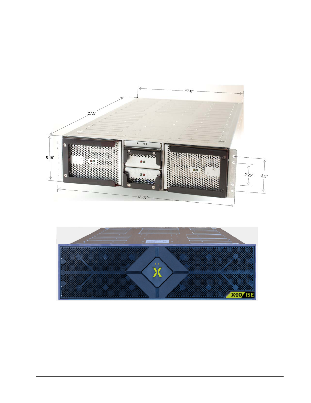
The ISE Storage Blade dimensions are shown in the figure below.
Figure 3. Front View with Dimensions (without Bezel)
For reference, the ISE, with bezel installed, is shown in the figure below.
Figure 4. Bezel
Note. The bezel is an integral component and should remain installed. The two LEDs and the “X” provide
status indications.
Xiotech—Proprietary 160337-000 Rev D, 30 September, 2013 Page 9
Page 18

ISE User GuideUser Guide Introduction
Site Requirements
The following tables present crucial environmental requirements for the ISE Storage Blade.
Environment Requirement
Operating temperature 10–35 degrees C
Operating humidity 20–80% (Non-condensing)
Operating altitude -1,000.6562–10,000 feet (-305–3,048 meters)
Heat dissipation 2,050 btu per hour
Loading weight Minimum
DataPac (varies by model) ~13–24 pounds (~5.9–10.9 kg)
Model 2400 without DataPacs ~72.3 pounds (~32.9 kg)
Model 2400 with DataPacs (2) ~97.9–120 pounds (~44.5–54.5 kg)
Power
Input voltage 100–240 Volts AC
Input frequency 50–60 Hertz
Maximum load 10–8 Amps
Connectivity
Host interface Eight port 8Gb FC
Table 2: ISE Site Requirements
Requirement
Requirement
Page 10 160337-000 Rev D, 30 September, 2013 Xiotech—Proprietary
Page 19

Installation ISE User Guide
Installation
The ISE Storage Blade is a 3U, rack-optimized unit for installation into a server rack using the supplied custom
rails and conforming to the specifications defined in this section. Before installation, it is a good practice to
review the support matrix at
The
ISE consists of five different Field Replaceable Units (FRUs) plus a bezel. The unit is shipped with the
MRC, power supply, and supercapacitor FRUs pre-installed. The DataPacs are packaged individually.
Overview
The ISE Storage Blade comprises five different major components, shown below, plus a bezel (not shown).
www.X-IO.com
for the latest information on supported configurations.
Figure 5. Assembly Overview
In addition to the five different major components (eleven in all), there is one minor component, the bezel. This
bezel is an integral component of the ISE. All ISE Storage Blade components must be installed during normal
operation and removed only during maintenance operations.
Xiotech—Proprietary 160337-000 Rev D, 30 September, 2013 Page 11
Page 20
ISE User Guide Installation
Rack ISE Chassis
The ISE chassis should be installed using the supplied rail kit into a rack before inserting the DataPacs as
described here.
Install Rail Kit
Before an ISE Storage Blade can be installed in a rack, the custom rails must be installed. The custom rail kit
mounts easily into both round-holed and square-holed racks.
Round–Holed Rack Mounting
To install the adjustable rail kit into a round–holed rack, do the following:
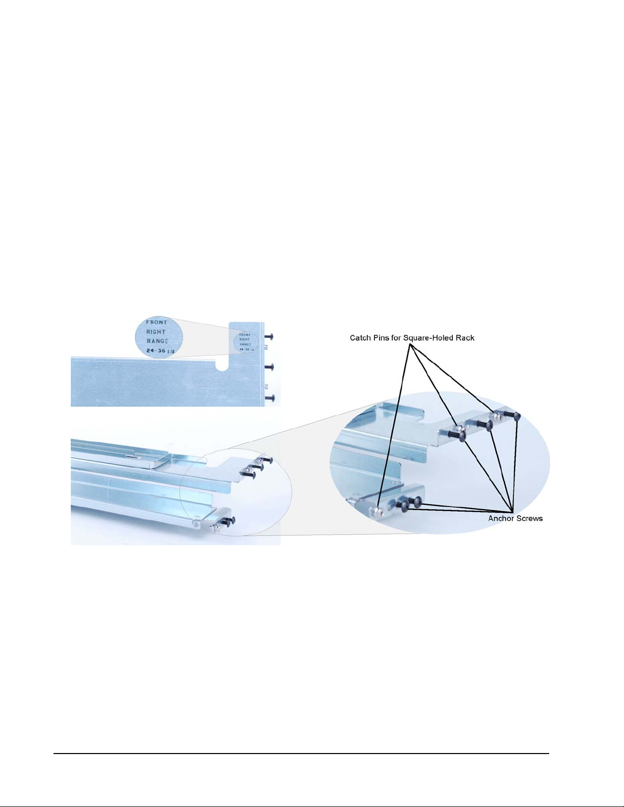
1. Remove the rail kit with anchoring screws from its packaging.
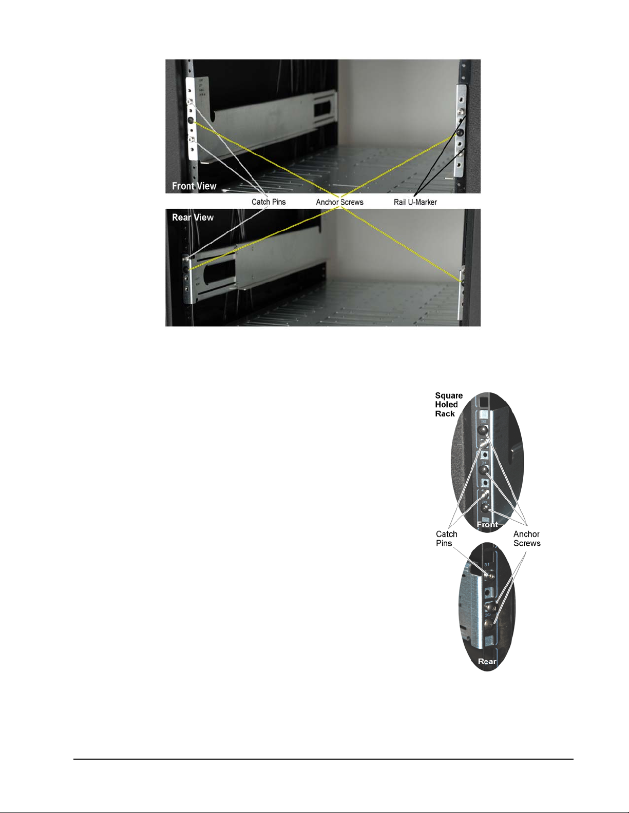
2. Install both rails, as labeled, into the server rack by placing the front rail bracket over the three mounting holes and inserting at least one rack screw, anchoring the rail front to the rack (Figure 7).
3. Extend the rear slider until the rear mount aligns on the rack’s back mounting face, securing it with two of the supplied rack screws (Figure 7).
4. Secure the rail, at the front, with three of the rack screws supplied in the rail kit.
Figure 6. Adjustable Rail Kit
Page 12 160337-000 Rev D, 30 September, 2013 Xiotech—Proprietary
Page 21
Installation ISE User Guide
Figure 7. Installed Rail Kits
Square–Holed Rack Mounting
To install the adjustable rail kit into a square–holed rack, do the following:
1. Remove the rail kit with anchoring screws from its packaging (Figure
6 on page 12).
2. Install both rails, as labeled, into the server rack by inserting the rail
mounting catch pins into the front square-holed rack mountings from
behind—see figure to right.
3. Extend the rear slider until the rear catch pin engages with the rear
rack mount—see figure to right.
4. Secure the rail, at the rear, with two of the rack screws supplied in
the rail kit.
5. Secure the rail, at the front, with three of the rack screws supplied in
the rail kit.
Xiotech—Proprietary 160337-000 Rev D, 30 September, 2013 Page 13
Page 22
ISE User Guide Installation
Install ISE Chassis
The ISE chassis can be installed into a rack as it is in the shipping box before inserting the DataPacs as
shown. The chassis as it is shipped weighs about seventy-three pounds and it is recommended that two people co-lift the chassis from the collapsed shipping carton and slide it into the rack.
1. Remove the static shield bag from the chassis
and slide the chassis (as shipped) into the
server rack on the custom rails from the front,
oriented with the system display
2. Secure the chassis to the rack with the four mounting screws included in the hardware packet.
Note. The ISE can weigh up to 120 pounds
with all components installed.
on the top.
Figure 8. Inserting ISE Chassis
Front View
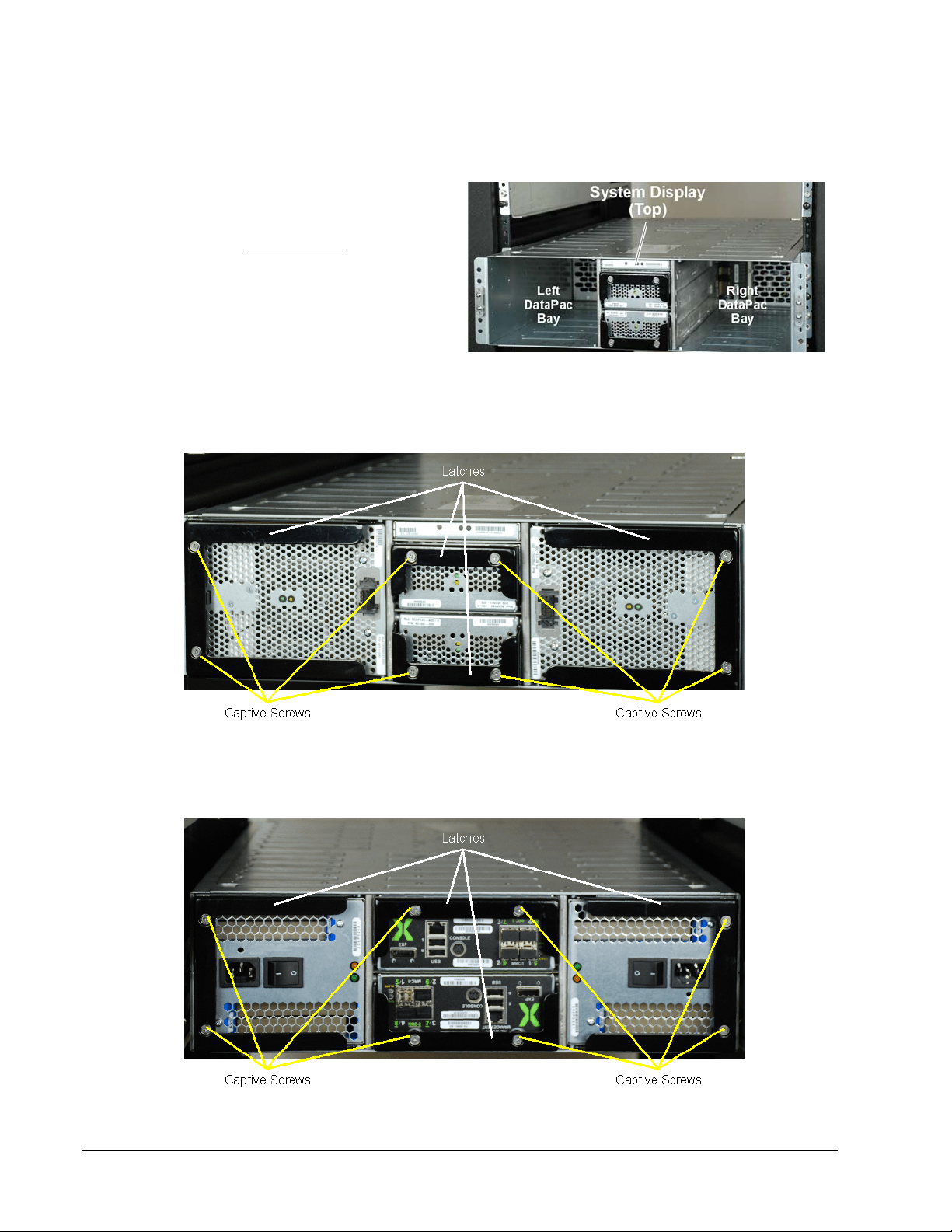
The ISE is shown from the front with the latches and captive screws pointed out.
Figure 9. ISE Front View
Rear View
The ISE is shown from the rear with the latches and captive screws pointed out.
Figure 10. ISE-2 Rear View
Page 14 160337-000 Rev D, 30 September, 2013 Xiotech—Proprietary
Page 23

Installation ISE User Guide
Install DataPacs
The ISE Storage Blade ships with two DataPacs or one DataPac and one DataPac Filler. The bay to left of the
supercapacitor bays must always be populated with a DataPac.
CAUTION—Handling DataPacs
DataPac units are delicate and should always be handled with care. This is extremely important during the
unpacking of DataPacs and subsequent handling leading to DataPac insertion into the chassis. The latch han-
dle located on each DataPac unit is not intended for use as a carrying handle. Careless handling can damage
the unit.
Proper and improper handling of a DataPac is demonstrated below.
Figure 11. DataPac Handling Proper and Improper
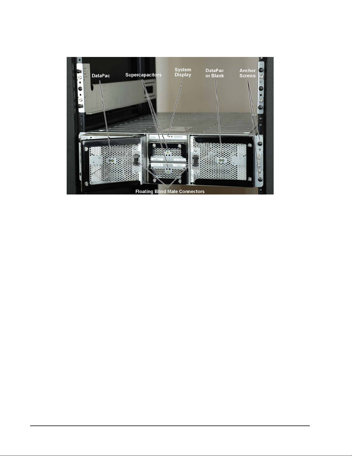
Unpack a DataPac and insert it gently into the front of the chassis with the black latch fully extended and oriented as shown in Figure 12 below. When the DataPac is firmly in place, secure the DataPac by closing the
black latch handle and tightening the two captive screws (Figure 9 on page 14) until snug—do not overtighten—to secure the DataPac (Figure 12). Repeat this step for the other DataPac.
Notes:
[1] All DataPac latch handle captive screws must be firmly tightened prior to initial ISE Storage Blade power
on to prevent the inadvertent pulling of a DataPac and resultant data loss.
[2] DataPacs should never be removed from an initialized ISE Storage Blade unless it is powered off or a
DataPac remove command has been issued.
[3] If the DataPac captive screws are not tightened, the DataPac status indicates
Insecure DataPacs
.
Xiotech—Proprietary 160337-000 Rev D, 30 September, 2013 Page 15
Page 24
ISE User Guide Installation
Single DataPac Installation
For single DataPac installations, the DataPac must be installed to the left of the supercapacitor bays and the
DataPac Filler must be installed to the right of the supercapacitor bays.
Figure 12. ISE Chassis Front View—DataPac and Supercapacitor Insertion
Install Supercapacitors
The supercapacitors come pre-installed in the ISE chassis. In the event there is a need to install a supercapacitor unit, insert the supercapacitor into the chassis gently from the front, oriented as shown in Figure 12 and
with the black latch fully extended. When the supercapacitor is firmly in place, return the black latch to its
closed position and tighten the two captive screws (Figure 9 on page 14) until snug—do not overtighten.
Install Power Supplies
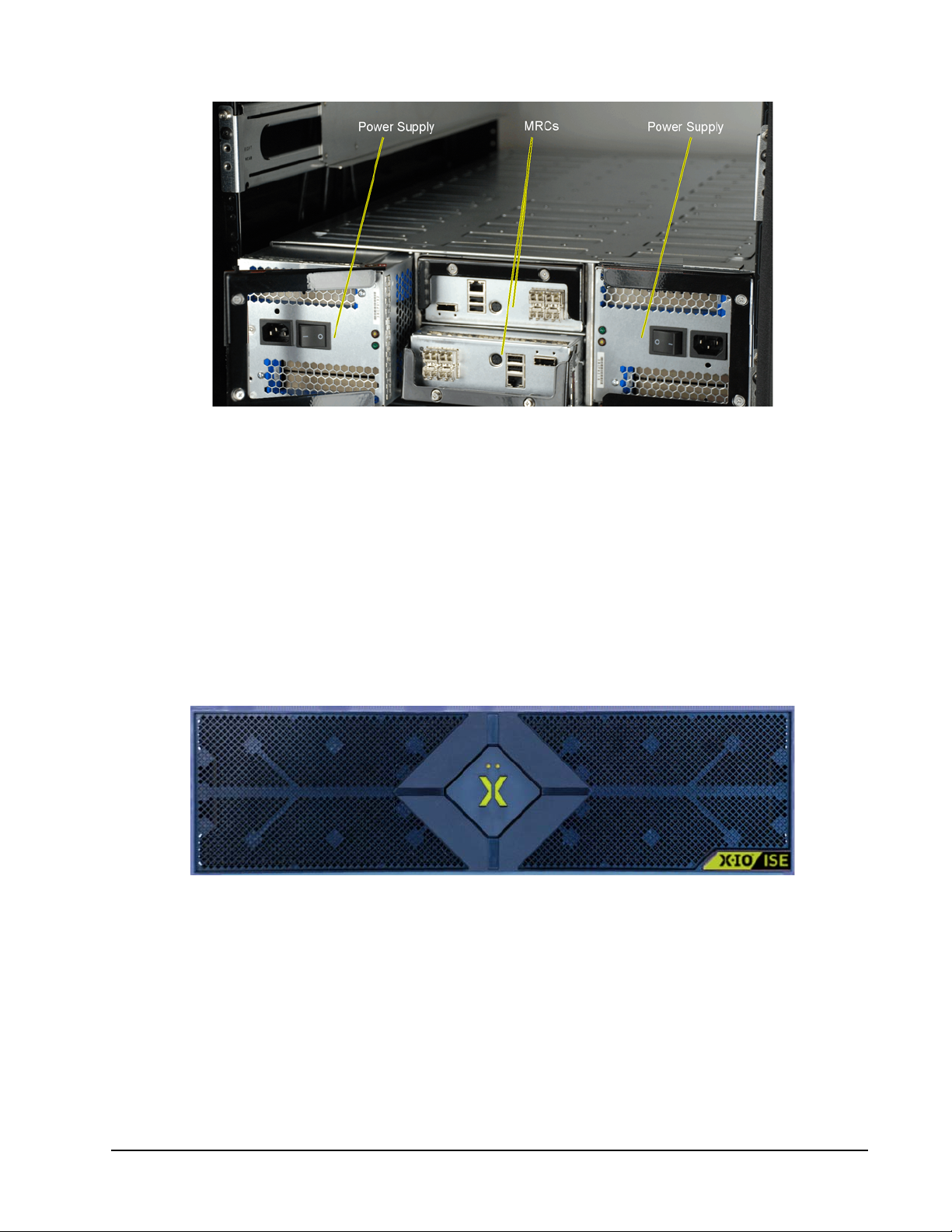
The ISE comes with the power supplies pre-installed. In the event there is a need to install a power supply unit,
insert the power supply into the chassis gently from the rear, oriented as shown in Figure 13 and with the black
latch fully extended. When the power supply is firmly in place, return the black latch to its closed position and
tighten the two captive screws (Figure 10 on page 14) until snug—do not overtighten.
Page 16 160337-000 Rev D, 30 September, 2013 Xiotech—Proprietary
Page 25
Installation ISE User Guide
Figure 13. Rear View—Power Supply, MRC Insertion
Install MRCs
The MRCs come pre-installed in the ISE chassis. In the event there is a need to install an MRC, insert the unit
gently into the chassis from the rear, oriented as shown in Figure 13 and with the latch handle fully open, pushing firmly until the MRC seats. With the MRC firmly in place, secure the unit by closing the black latch handle
and tightening the two captive screws (Figure 10 on page 14) until snug—do not overtighten. Repeat this step
for the other MRC.
Install Bezel
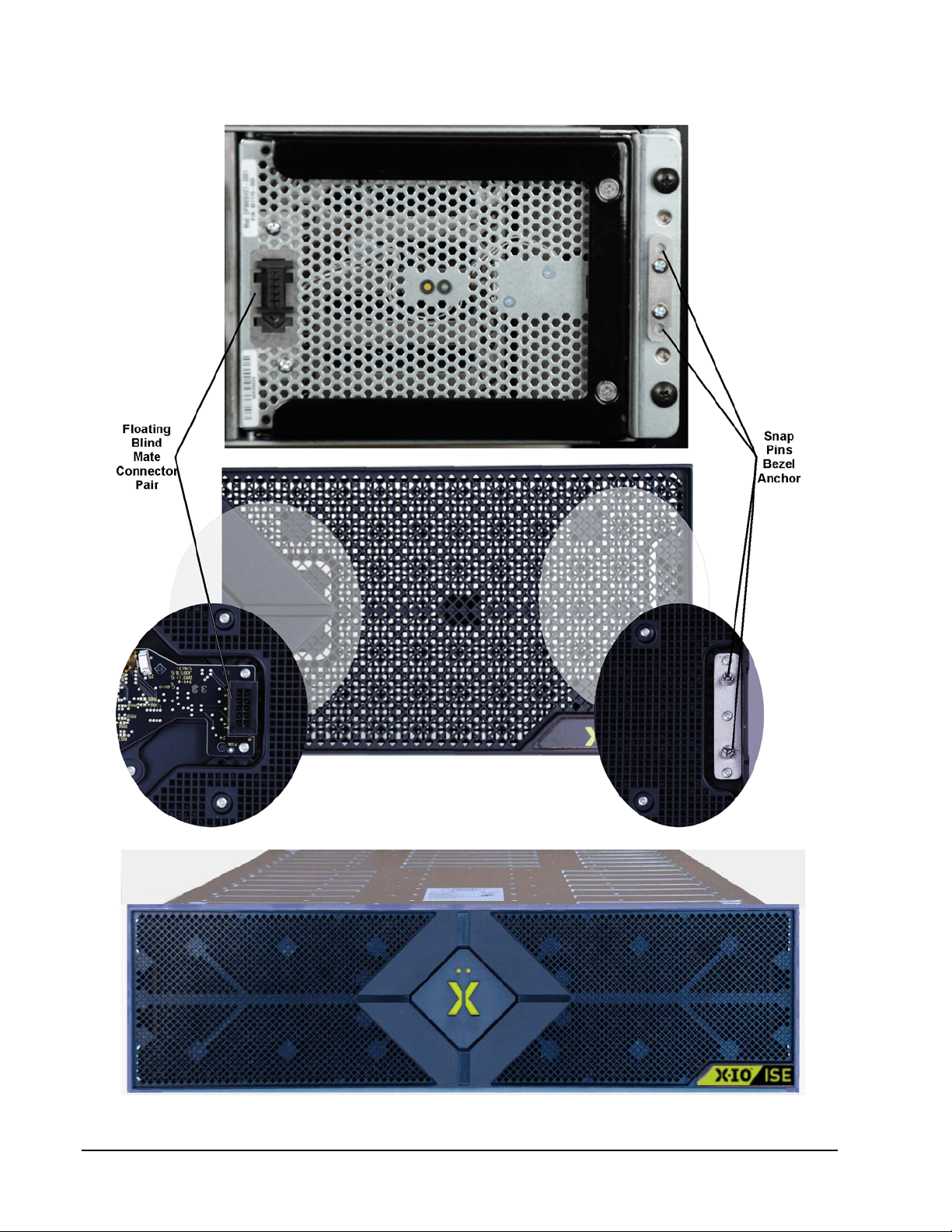
The ISE bezel, shown below, is an integral component that snaps onto the chassis at each end with snap pins
(see Figure 15 on page 18).
Figure 14. Bezel
To install the bezel, align the bezel as shown in figure 15 such that the snap pins seat into the anchors on the
chassis. With the snap pins seated, firmly press the bezel onto the chassis. The floating blind mate connectors
(See Figure 15 on page 18) automatically align and mate, connecting the bezel circuitry to the ISE circuitry.
Xiotech—Proprietary 160337-000 Rev D, 30 September, 2013 Page 17
Page 26
ISE User Guide Installation
Figure 15. Snap Bezel Into Place
Figure 16. Bezel Installed
Page 18 160337-000 Rev D, 30 September, 2013 Xiotech—Proprietary
Page 27
Installation ISE User Guide
Recommended Cabling
Cabling an ISE involves attaching the power cords, Ethernet cables, service console cable (one), and Fibre
Channel cables to the associated connectors on the ISE in a manner similar to that shown, figures 18 and 19.
The important issue with cabling is to run the cables with enough slack to permit the hot-replacement of any
component without interruption in ISE data services.
FRU Locations
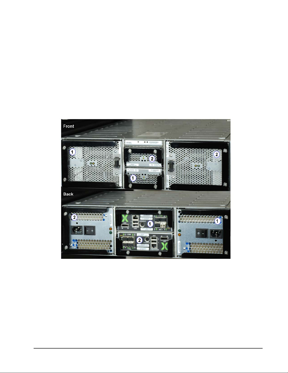
The following figure identifies the ISE components (FRUs) by their location number. That is, when referring to
DataPac one (1), the specified DataPac is located to the left when viewing the ISE from the front. In Figure 17
(following page), this DataPac is identified with the number
When viewing the ISE from the back, the location numbering is in reverse order. That is, when referring to
power supply one (1), the specified power supply is located to the right. In Figure 17 (following page), this
power supply is identified with the number
1
on the back view.
1
on the front view.
Figure 17. FRU Locations Numbered
Xiotech—Proprietary 160337-000 Rev D, 30 September, 2013 Page 19
Page 28

ISE User Guide Installation
Storage Area Network (SAN)
In a SAN environment, the ISE connects to a host through the fabric (see the online compatibility matrix at
http://support.XIOstorage.com
age Blade management interfaces are network accessible through the Ethernet ports.
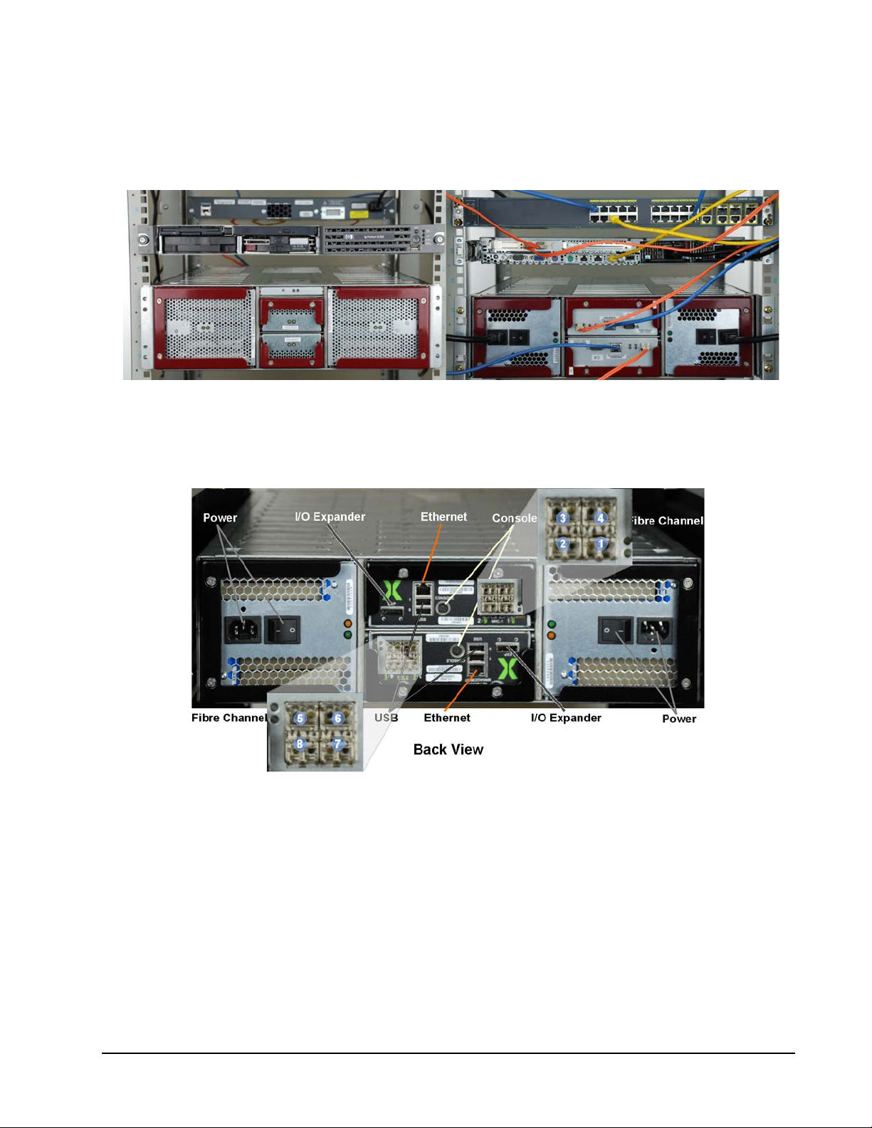
In the example below (Figure 18), the ISE connects to the blade servers through built-in Fibre Channel
switches.
) and its Fibre Channel ports. In this network-attached environment, the ISE Stor-
Figure 18. ISE Sample Blade Server Cabling
Note. While figures 18 and 19 show ISE-1 units, the arrangement and cabling techniques remain applica-
ble to the ISE-2, Hyper ISE, and ISE 7-Series.
Page 20 160337-000 Rev D, 30 September, 2013 Xiotech—Proprietary
Page 29
Installation ISE User Guide
Direct Attach (DAS)
An ISE can attach directly to a host through the Fibre Channel ports (see the online compatibility matrix at
http://support.XIOstorage.com
Notice that the cables are routed to avoid blocking hot-replacement of components. The orange Fibre Channel
cables connect directly from the host HBAs to each MRC Fibre Channel Port. The two blue Ethernet cables
connect the ISE Ethernet ports to a network switch for management interface access.
Figure 19. ISE Sample DAS Cabling
). Below is an example of direct attach (or direct connect) of an ISE to a host.
Connectivity
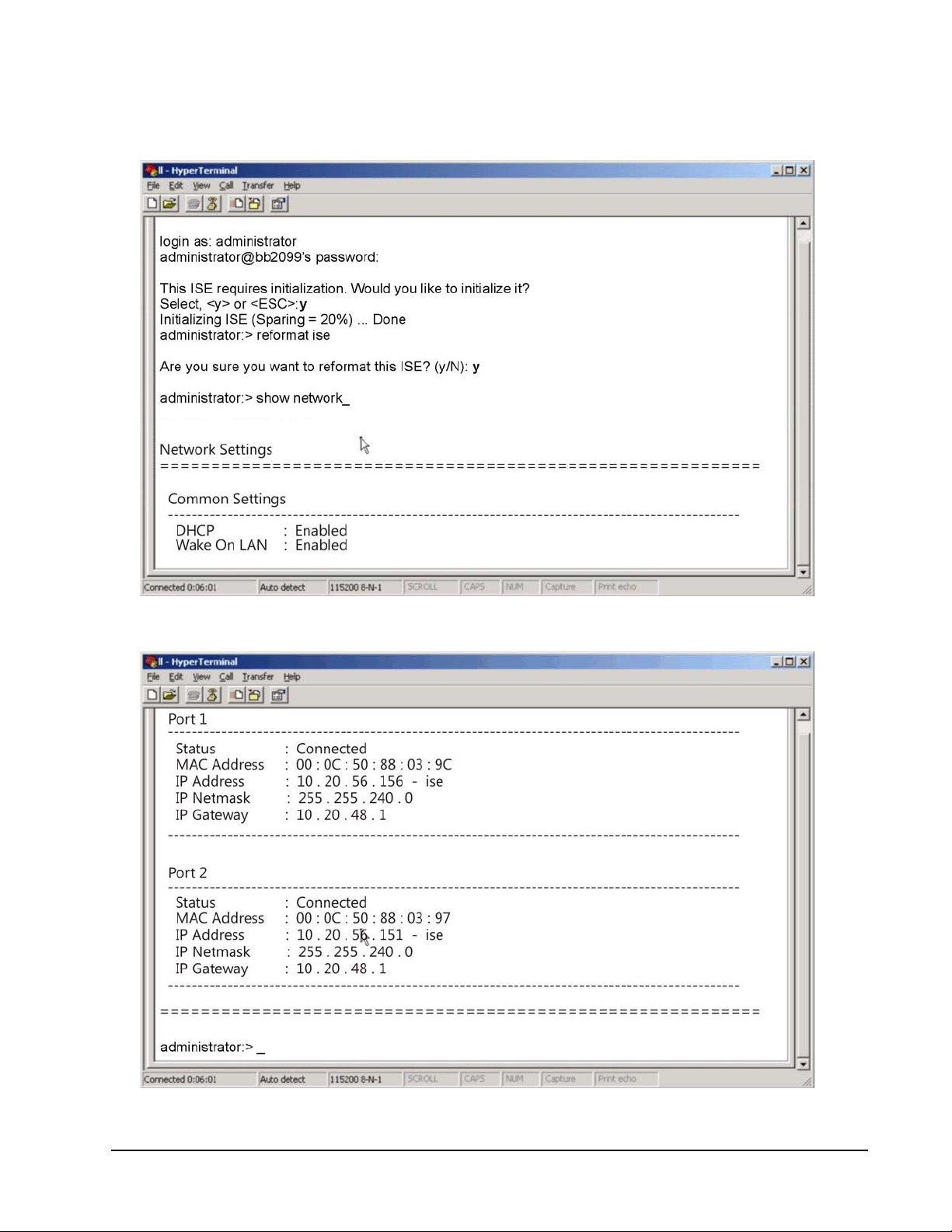
ISE connectivity includes the following different ports (Figure 20).
Figure 20. ISE Ports View
ISE Connectors
• MiniDIN–for connecting a service console (PCCABLES.COM, P/N 70810)
• Ethernet–for Web management interface and Wake-On-LAN (10/100/1000 Mbps)
• Fibre Channel–for volume data accessed by the host (4/8 Gbps)
• I/O Expander–SAS, wide port reserved for future use
• USB–reserved for service
Note. All management commands are communicated through the Ethernet interface.
Xiotech—Proprietary 160337-000 Rev D, 30 September, 2013 Page 21
Page 30

ISE User Guide Installation
SFP Installation
When additional SFP (Small-Form-Factor Pluggable) Fibre Channel connector modules are purchased, installation is required. Install SFP modules using the following procedure:
1. Remove the protective plug from a port on an ISE MRC—three ports are available on each MRC.
2. Gently insert the replacement SFP fully into the chassis. If a solid resistance is encountered, remove the SFP, turn it over, and re-insert it.
3. When the SFP is fully inserted, engage the bail if needed to secure it in the MRC. When properly seated, the SFP is flush with the MRC latch handle.
4. Insert a Fibre Channel cable gently into the SFP while gently pinching the cable connector.
Service Console
The very first time an ISE is powered on, a service console is required to determine or change the IP
addresses. The service console can be a laptop or other computer that provides serial port connectivity. Connect the computer to one of the serial ports on the ISE with the supplied serial cable.
Note. A single cable can be plugged into either service console port.
With a service console connected, follow the procedure below to establish a service console connection:
1. Open a terminal emulation application on the service console.
2. Set the terminal emulation application properties for the appropriate COM port as shown in Table 3.
Setting Value
Bits per second (Baud rate) 115200
Data bits 8
Parity bit none
Stop bit 1
Flow control none
Any other settings default
Table 3: COM Port Settings
3. Press
E
NTER
on the service console (or use whatever method is provided by the application in use) to
initiate a terminal console session and receive a login prompt from the ISE (Figure 21 on page 25).
Management Console
The ISE management console is accessed through the Ethernet network using either or both ISE IP addresses
(see “Reserved Characters” on page 29 and “Command Line Interface” on page 35).
Orchestrator
Orchestrator provides storage management and provisioning services for ISE Storage Blade systems. This
replaces the ISE Web Management interface (Classic View) on ISE-2 and ISE-3 systems and approaches ISE
management from a global perspective. All managed ISEs are listed in the left navigation pane and are
accessed by clicking on an ISE name. Orchestrator also presents statistics for the entire field of networked
ISEs. See the Orchestrator User Guide for details.
Page 22 160337-000 Rev D, 30 September, 2013 Xiotech—Proprietary
Page 31

Installation ISE User Guide
Fibre Channel Connectivity
The ISE can connect to a host directly or through a Fibre Channel switch (see the online compatibility matrix at
http://support.
the following specifications and standards:
• Fibre Channel Framing and Signaling (FC-FS) Revision 1.90,
• Fibre Channel Link Services (FC-LS) Revision 1.0 to SCSI Primary Commands (SPC-3) Revision 22a,
• SCSI 3 Block Commands (SBC) Revision 8C and
• SCSI Architecture Model 3 (SAM-3) Revision 13 of the SCSI specifications.
Auto-Negotiation
The ISE provides Auto-Speed-Negotiation for all supported modes; Model 1400–2 and 4 Gbps and Model
2400–2, 4, and 8 Gbps.
Zoning Requirements
X-IO
.com). To facilitate Fibre Channel connectivity, the ISE interfaces are designed to conform to
For a best practices discussion of ISE zoning requirements, refer to the Support Matrix at
IO.com/supportmatrix
.
http://support.X-
First-Time Power On
When powering on the ISE for the first time, follow the steps outlined below.
Pre-power On Check
Before powering on, check the following:
1. Components–all components are completely inserted and secured
2. Latch handles–all latch handles are locked and secured with the captive screws
3. Service console port–at least one service console port is cabled to a service laptop or PC
4. Ethernet ports–both Ethernet ports are connected, secure, and routed for hot component replacement
5. Fibre Channel ports–at least one Fibre Channel port on each MRC is connected, secure, and routed to
allow hot component replacement (see the ISE-2 Storage Blade User Guide for port details)
Power On Procedure
With a service console connected, turn on both power supply switches and confirm that:
• All fans are running
• All green component LEDs are lit (may take a few minutes)
Xiotech—Proprietary 160337-000 Rev D, 30 September, 2013 Page 23
Page 32

ISE User Guide Installation
If there are any amber LEDs lit, follow the guide below for the appropriate action.
Component Corrective Action
Supercapacitor
Power Supply
SFP
MRC Contact X-IO Customer Support.
DataPac Contact X-IO Customer Support.
Chassis Contact X-IO Customer Support
Table 4: Amber LEDs—Corrective Action
Contact X-IO Customer Support for a replacement component and then follow the procedure in the ISE2 User Guide.
Contact X-IO Customer Support for a replacement component and then follow the procedure in the ISE2 User Guide.
Contact X-IO Customer Support for a replacement component and then follow the procedure in the ISE2 User Guide.
When the ISE system is running with no amber LEDs lit, both IP addresses can be determined and configured.
ISE IP Addresses
With a terminal console session established through either service console port (see “Service Console” on
page 22), at the ISE login prompt (Figure 21 on page 25):
1. Log in with the following user credentials:
User name: administrator
Password: administrator
On a non-initialized ISE, the console displays the following message:
This ISE requires initialization. Would you like to initialize it?
Select, <y> or <ESC>:
2. Press
E
SC
to skip the initialization process (initialization will be done later); the Skipping
initialization message is displayed followed by the CLI prompt, and the service console is ready to
accept commands (Figure 21).
Page 24 160337-000 Rev D, 30 September, 2013 Xiotech—Proprietary
Page 33
Installation ISE User Guide
Determine IP Addresses
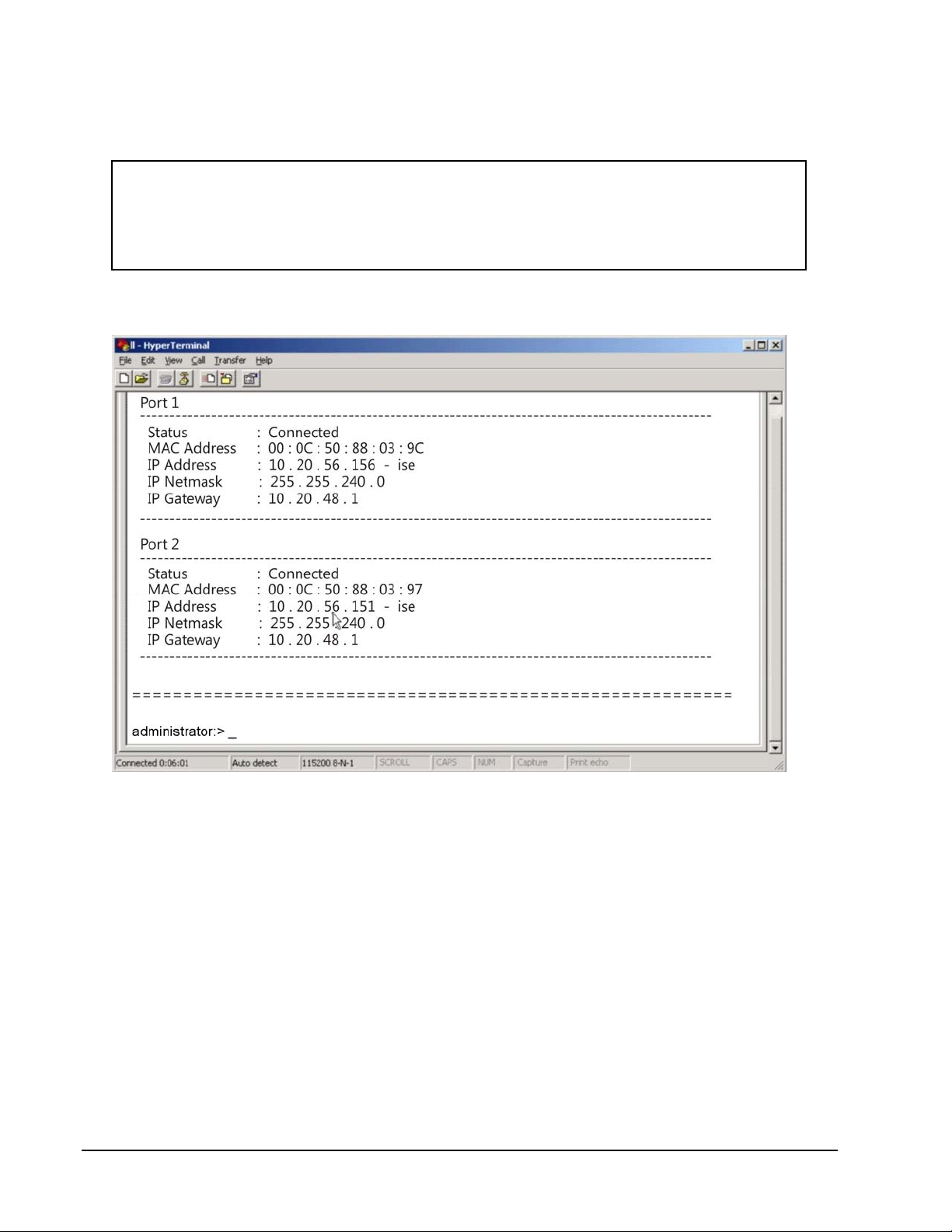
To determine whether the ISE is using DHCP or a default IP address, enter the show network command.
The network settings are displayed as shown in figure 21.
Figure 21. Show Network Command
Figure 22. Show Network Command Response
Xiotech—Proprietary 160337-000 Rev D, 30 September, 2013 Page 25
Page 34
ISE User Guide Installation
configure --dhcp=off --ipaddress1=<mrcaddr1> --netmask1=<netmask>
--gateway1=<gateway> --ipaddress2=<mrcaddr2> --netmask2=<netmask>
--gateway2=<gateway>
Changing Network Settings to Static (optional)
The ISE Storage Blade defaults to DHCP Enabled. If Static addressing is required, execute the command
shown in the following figure (see Figure 23 and the example in Figure 23 on page 26).
Figure 23. CLI Configure DHCP
An example is shown in Figure 24.
Figure 24. Changing IP to Static—Example
Installation Complete
The ISE installation is complete; the service console should be logged out of and a management interface connection opened. The three management interfaces, accessible through the network, are:
•
X-IO
Orchestrator storage management and provisioning service
•
X-IO
Web Management Interface, referred to as the Classic Web-Mgt
•
X-IO
Command Line Interface, referred to as the CLI
Orchestrator Storage Management
The Orchestrator is used to browse and manage all networked ISEs. Where the Classic Web-Mgt requires logging on to each ISE to manage that ISE, the Orchestrator permits management of all ISEs from any ISE-2 or
ISE-3 system running Orchestrator. Orchestrator also presents statistics for an entire field of networked ISEs.
Page 26 160337-000 Rev D, 30 September, 2013 Xiotech—Proprietary
Page 35

Installation ISE User Guide
Web Management Interface
The Web Management Interface, described throughout this document, is used to configure, monitor, and manage the ISE.
Command Line Interface
The Command Line Interface, described throughout this document, can be used to configure, monitor, and
manage the ISE.
Additional Options
There are a number of additional options available for the ISE. Some of these (see “Related Documents” on
page 1) are:
• ActiveWatch—Part of an available
• ISE Analyzer—Appliance and Graphical User Interface for access to real-time and historical status,
configuration, and performance data from multiple ISEs
• ISE Mirroring
• ISE Multipath Suite
• ISE Manager
X-IO
Customer Support service
Initialize–Configure the ISE
Refer to sections “Power-up, Shutdown, Restart” on page 37 and “Initialize and Configure” on page 41 for
detailed instructions on how to initialize and configure the ISE.
Xiotech—Proprietary 160337-000 Rev D, 30 September, 2013 Page 27
Page 36

ISE User Guide Installation
Page 28 160337-000 Rev D, 30 September, 2013 Xiotech—Proprietary
Page 37

Management Tools ISE User Guide
Management Tools
The ISE provides three methods to manage its configuration and operation:
•The
•The
•The
This chapter presents the requirements and connection procedures for these methods.
Reserved Characters
X-IO
Web-based Management Interface (Web-Mgt)
X-IO
Orchestrator site-wide ISE management tool
X-IO
Command Line Interface (CLI)
The Web-Mgt and CLI accept special characters in text-entry fields except for those characters listed in the
table below.
Character Name
% percent
& ampersand
<less than
> greater than
\ back slash
‘ single quote
Table 5: Characters—Web-Mgt and CLI
The Orchestrator accepts special characters in text-entry fields except for those characters listed in the table
below.
Character Name
& ampersand
“ double quotes
/ forward slash
\ back slash
‘ single quote
Table 6: Characters—Orchestrator
Web-Based Management
The ISE contains two embedded Web-Based Management tools that respond to requests from a remote Web
browser. Multiple users may be connected to the ISE simultaneously. This section describes the requirements
and connection procedure for the Web management tools.
Xiotech—Proprietary 160337-000 Rev D, 30 September, 2013 Page 29
Page 38
ISE User Guide Management Tools
Browser Requirements
The remote Web browser used to manage the ISE can be on any computer on the Local Area Network and
must meet the following requirements.
Classic Web Interface (Web-Mgt):
• Browsers: Internet Explorer 6.0 and later, Opera 9.5 and later, Safari 3.1 and later
• JavaScript enabled
• XML/XSL rendering enabled
Orchestrator Web Management Interface:
• Browsers: Google Chrome and Safari 3.1 and later are recommended
• Internet Explorer has demonstrated some display issues
• JavaScript enabled
• XML/XSL rendering enabled
Terminology
The following introduces the two Web based management interfaces.
Web-Mgt
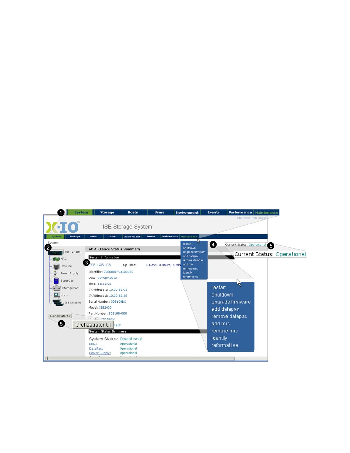
The Classic Web-Mgt uses the terminology described in the following figure (Figure 25).
Figure 25.
Page 30 160337-000 Rev D, 30 September, 2013 Xiotech—Proprietary
Web-Mgt
Overview—Elements
Page 39
Management Tools ISE User Guide
Element Name Description
1
2
3
4
5
6
Navigation bar Horizontal bar with navigation drop-down menus
Left navigation pane Tree format navigation to detailed component information
Detail pane Main area of view containing the view details
Drop-down menu Drop-down menu activated by hovering the pointer over a navigation bar item
Current status Dynamic display of the system status (Operational here)
Orchestrator UI Button to switch to Orchestrator
Table 7:
Web-Mgt
Elements
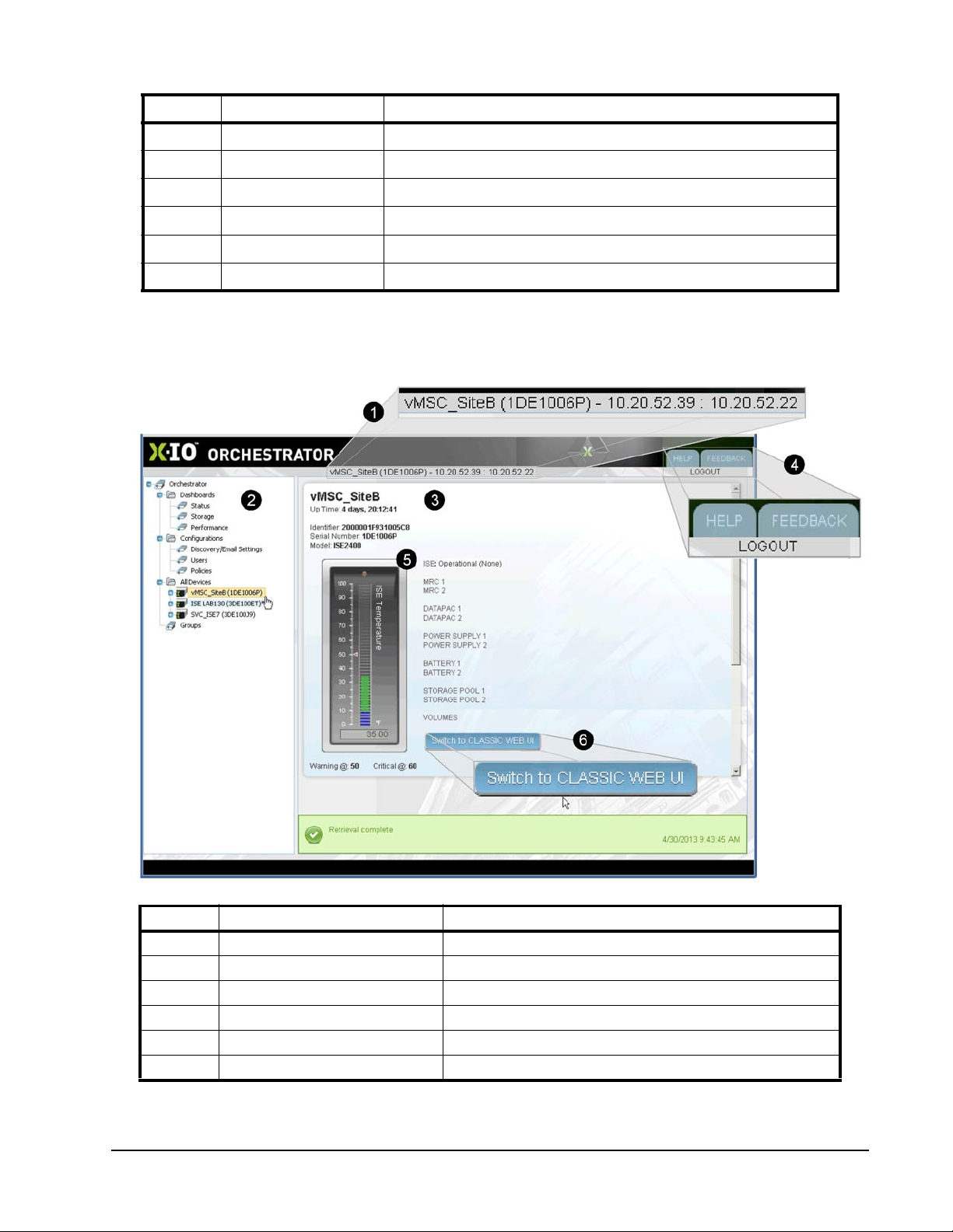
Orchestrator
The Orchestrator management tool (only available with ISE-2) uses the terminology described below.
Figure 26. Orchestrator Management Tool—Screen
Element Name Description
1
2
3
4
5
6
Table 8:
ISE name and IP addresses Identifies the ISE that is being viewed
Left navigation pane Tree format navigation to detailed component information
Detail Pane Area where selected details are presented
System buttons Help, Feedback, and log out buttons
General status Identifies selected ISE and presents its general state
Switch to Classic Web UI UI Button to switch to the Classic Web interface
Orchestrator
Elements
Xiotech—Proprietary 160337-000 Rev D, 30 September, 2013 Page 31
Page 40
ISE User Guide Management Tools
Logging In
This section describes the steps to log into the Web management tools. The user ID is a
dministrator
(case
dependent) and the default password for the first-time login, set by manufacturing, is administrator. The
password reverts to this default upon a reset to factory settings, during an ISE reformat (see “Reformat an ISE”
on page 142).
Web-Mgt
To log into the Web-Mgt (Classic) tool:
1. Obtain the IP address or host name of the MRCs from the site network administrator.
2. To log in to the target ISE, type the IP address or host name of one of the MRCs in the ISE into the browser’s Address field as shown in the following examples:
http://<static_ip_address> or
http://<dhcp_generated_address> or
http://<mrc_host_name>
3. Press
E
NTER
.
The System Login view appears.
4. Click
Login
.
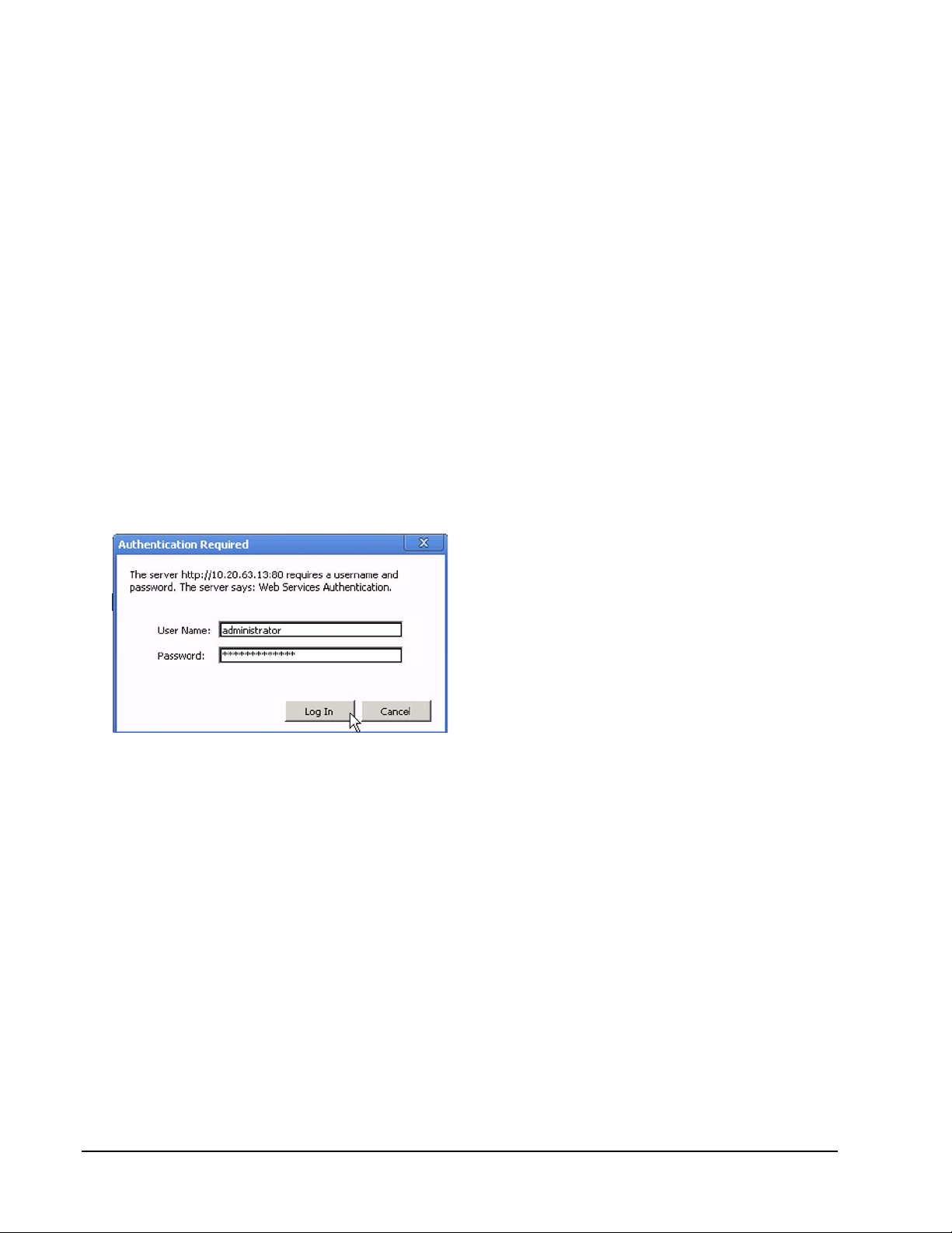
The System Authentication dialog appears.
Figure 27. Classic Login Authentication
5. Enter the login credentials as follows:
User name: administrator
Password: <password>
The default password for the first-time login is administrator.
6. Click
OK
.
The Web-Mgt is now running and Orchestrator is accessible to manage the site ISE systems.
Orchestrator
To log into the Orchestrator ISE management tool:
1. Enter the name or IP address for an ISE-2 (Model 2400) system
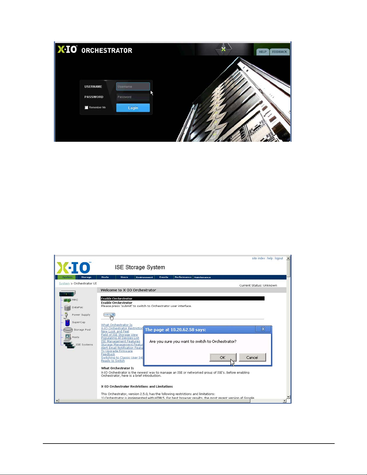
2. On the Orchestrator Login screen (Figure 28 on page 33) enter the User Name as administrator.
3. Enter the Password as administrator.
Page 32 160337-000 Rev D, 30 September, 2013 Xiotech—Proprietary
Page 41
Management Tools ISE User Guide
4. Click Login.
Figure 28. Orchestrator—Login Screen
Logging Out
To log out and return to the
1. Click
logout
in the upper right corner of the view (Figure 25 on page 30 and Figure 26 on page 31).
System Login
screen:
2. To exit from the Web-Mgt, click the browser close button and the browser window closes.
Switching to Orchestrator
To use
1. Click
2. Click
X-IO
Orchestrator, follow the steps below and refer to the Orchestrator User Guide:
Orchestrator UI
Submit
as show below.
in the left navigation pane (Figure 25 on page 30).
Figure 29. Switching to Orchestrator
Xiotech—Proprietary 160337-000 Rev D, 30 September, 2013 Page 33
Page 42
ISE User Guide Management Tools
3. Click OK to confirm the switch and the switch delay is marked by the screen shown below.
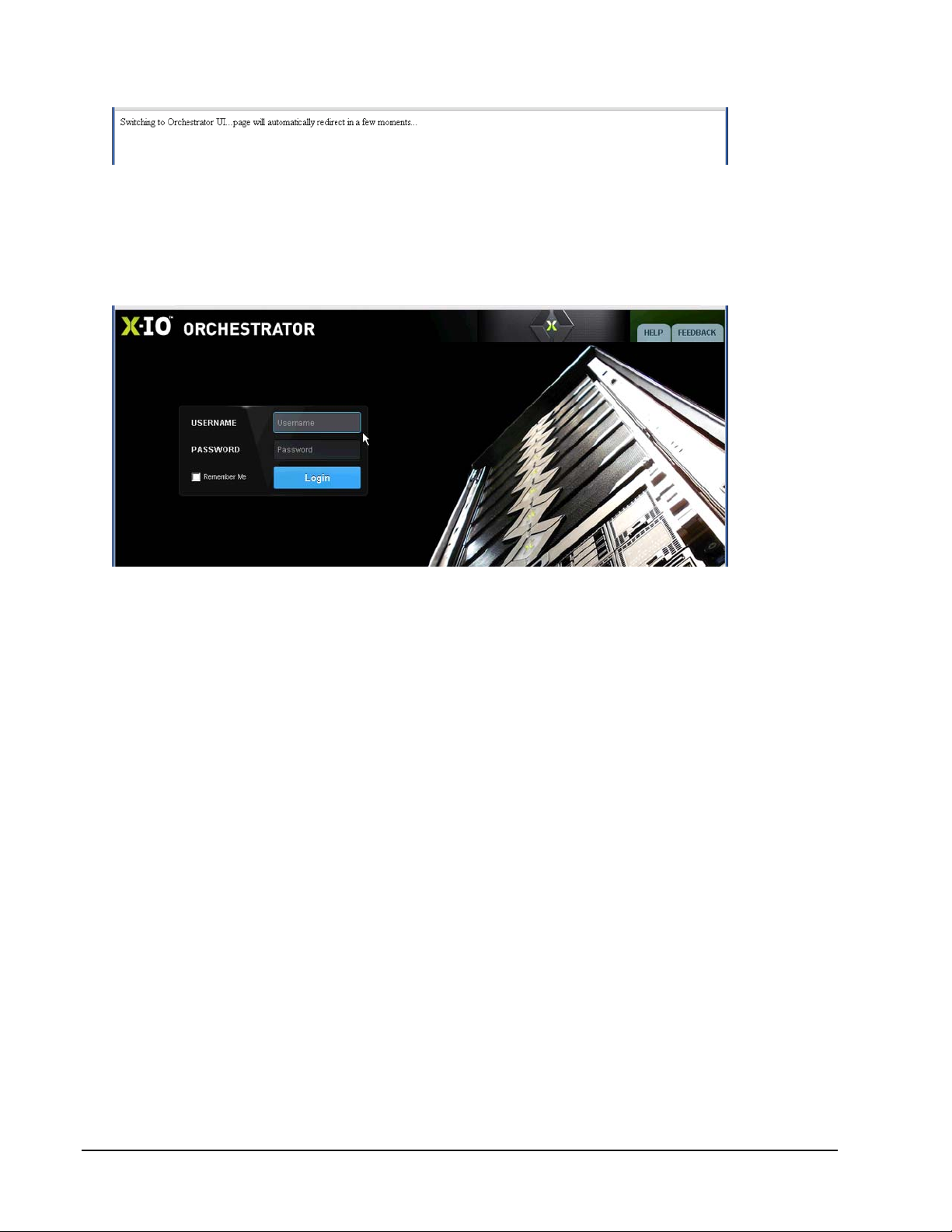
Figure 30. Switch to Orchestra Delay
This screen indicates “Switching to Orchestrator UI...page will automatically redirect in a few moments.”
4. On the Orchestrator Login screen (Figure 31 on page 34) enter the User Name as administrator.
5. Enter the Password as administrator.
6. Click Login.
Figure 31. Orchestrator—Login Screen
Site Index and Help
The Web-Mgt contains a Site Index, accessible in the upper right corner of the ISE window. The Site Index
view provides links to the various views in the Web-Mgt interface.
The Web-Mgt and Orchestrator both provide online Help, accessible in the upper-right corner of the ISE
window.
Navigation
After login, the At-A-Glance Summary appears. Figure 25 on page 30 shows this view and the major
navigation features of the Web-Mgt as follows:
• Horizontal navigation bar (1) appears at the top of every Web-Mgt page. When the pointer is hovered
over a navigation bar item, the associated menu list drops down.
• Left navigation pane (2) appears on the left of every Web-Mgt view. View a specific component by
clicking its icon in tree view. After configuration, many component views expand hierarchically.
Reserved Characters
The Web-Mgt and Orchestrator permit special characters in text-entry fields with the exception of those
characters listed in Table 5 and Table 6 on page 29.
Page 34 160337-000 Rev D, 30 September, 2013 Xiotech—Proprietary
Page 43

Management Tools ISE User Guide
Command Line Interface
The ISE contains an embedded Command Line Interface (CLI) that responds to commands entered at the CLI
prompt on a remote console or invoked through a script. Standard command line protocol (such as terminating
a command line with
Multiple users may be connected to the ISE simultaneously. This section describes the requirements and
connection procedure of the CLI. To aid in script development, Appendix B presents the Help file from the
Command Line Interface, listing the commands and options available.
Remote Console Requirements
The remote console used to control the ISE may be any terminal connection application that has Secure Shell
connection capability (protocol version 2) through port 22.
Secure Shell connection capability is a secure form of telnet. The ISE will not respond to a regular telnet
connection request.
Connecting
This section describes the steps to connect to the ISE through the remote console.
1. To connect to the target ISE, use any terminal connection application on the remote console and configure
it for SSH service on port 22.
E
NTER
) applies.
2. Type the IP address or the host name of one of the MRCs in the ISE into the application’s connection field
and connect.
The application requests SSH access credentials.
3. Enter the access credentials as follows:
User name: administrator
Password: <password>
The user password for the first-time login, built into the ISE during its manufacture, is administrator. During
the first-time login, the system prompts for entry of a new password. If the password administrator is
rejected, check with the network administrator to obtain the current valid user password.
4. Connect and the prompt appears.
5. CLI commands can now be entered to control the ISE as described throughout this document. Enter help
at the prompt to display a list of available commands.
6. To exit from the CLI, type exit or quit at the prompt.
Reserved Characters
The CLI permits special characters in text-entry fields with the exception of those characters listed in Table 5
on page 29. An argument in a CLI field may contain spaces if the entire argument entry is enclosed in quotation
marks.
Xiotech—Proprietary 160337-000 Rev D, 30 September, 2013 Page 35
Page 44

ISE User Guide Management Tools
Page 36 160337-000 Rev D, 30 September, 2013 Xiotech—Proprietary
Page 45
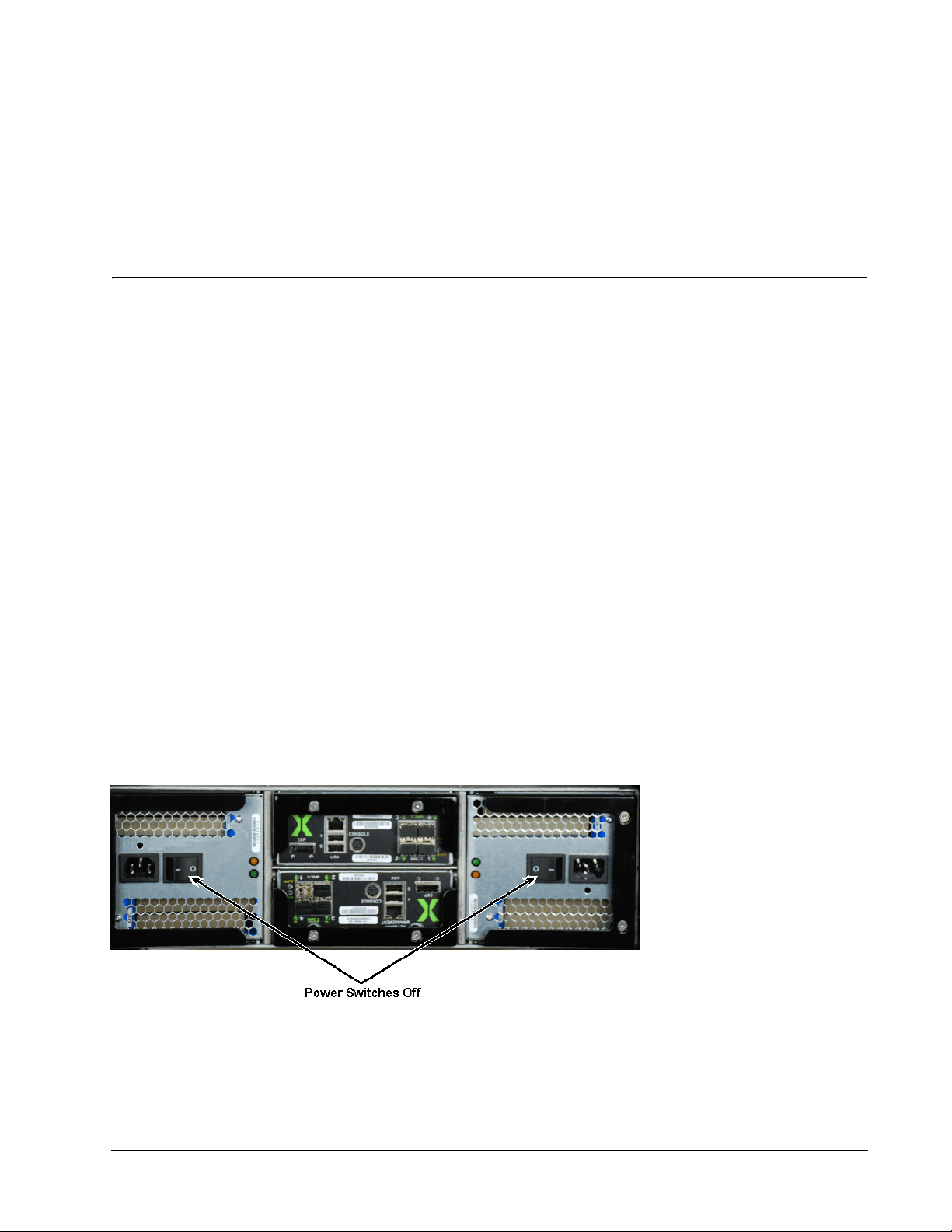
Power-up, Shutdown, Restart ISE User Guide
Power-up, Shutdown, Restart
This chapter describes the power-up, shutdown, and restart functions of the ISE and details the steps to
perform them:
• Power-up (see “Power On State” on page 37)
• Shutdown (see “Shutdown” on page 39)
• Restart (see “Restart” on page 39)
The ISE is connected to two separate and independent AC sources by two power cords connected to the ISE
power supplies. Each power supply unit has a power switch as shown in Figure 32. Connect the ISE power
cords to appropriate AC receptacles only after first confirming that the power switches on the ISE are in the
OFF
position.
ISE Power States
The ISE has three power states as follows:
• Powered On—ISE is in service
• Powered Off—ISE is out of service, can be powered up manually
• Standby—ISE is out of service, can be powered on with WOL
Power On State
An ISE in the powered-on state is fully functional with AC power applied to all components and all green LEDs
are lit.
Figure 32. Power Switches
Xiotech—Proprietary 160337-000 Rev D, 30 September, 2013 Page 37
Page 46

ISE User Guide Power-up, Shutdown, Restart
Power Off Stat e
Table 9 on page 38An ISE in the powered off state is totally without AC power. That is, all ISE components are
without power and all LEDs are off. To place the ISE in the power-off mode, put both power supply switches
into the
both power supplies, putting them into the
Off
position. To power up the ISE from the power-off state, press the power supply rocker switch on
ON
position.
Standby State
In the standby state, an ISE has power to the Ethernet ports and to the System Status Module LED (see
Table 24 on page 102). In standby mode, the LED is lit amber. When Wake-on-LAN (WOL) is enabled, the
Ethernet ports monitor the network for a wake-up command (magic packet), sent by certain third-party utilities,
to restart the ISE remotely. See “Wake-on-LAN (WOL) Service” on page 51 for details.
To power up the ISE from the standby state:
• If the Wake-on-LAN service is enabled (see “Wake-on-LAN (WOL) Service” on page 51), use a third-party
utility to send a magic packet on the network to one of the ISE’s two Ethernet port addresses.
• If the Wake-on-LAN service is disabled, toggle both power switches
on both supplies are in the
Off
position concurrently for five seconds.
The power off and standby states and the powerup actions are summarized in Table 9.
State Power Condition Action Powerup Action
Press power switch on both power
Power off
Standby
No power to all components
Power is supplied to
Ethernet ports and
System Status Module
LED
supplies to
WARNING: DO NOT DO THIS as a
means of shutting down the ISE.
Shut down ISE from Web-Mgt or CLI
Table 9: Power Off and Standby States
OFF.
Off
and On, ensuring that the switches
Press power switches on both supplies to
ON
.
If WOL service is enabled, send magic
packet on network to one of ISE’s two Ethernet port addresses
OR
Press power switches on both supplies to
On
(if already on, press both switches simultaneously to
to
On
Off
, wait 5 seconds, then press
).
When the ISE is powered on from the power-off or standby states, it performs a cold boot. Boot types are
summarized in the following table (Table 10).
Boot Type Conditions Inducing Boot Type Characteristics
Power applied (power off or standby)
Remote start by WOL packet from
standby state
Cold boot
Hot boot
Restart, Reformat, and Remove/Add
MRC functions from Web-Mgt or CLI
Some firmware exceptions causing ISE
reboot
Failover
Some operations (such as Add MRC)
Some firmware exceptions causing ISE
reboot
Page 38 160337-000 Rev D, 30 September, 2013 Xiotech—Proprietary
System performs self-test of subcomponents
ISE performs subset of self-test of subcomponents
Effects on outstanding host I/O requests:
• One MRC cold boots, the surviving MRC processes all host
requests with no impact on host
• Both MRCs cold boot simultaneously, host requests may time
out, causing the host to see I/O errors
Reboot process completes quickly
Effect on host I/O requests that are outstanding when the hot boot
occurs: requests are completed within the host’s timeout period
without impact on the application
Page 47

Power-up, Shutdown, Restart ISE User Guide
Boot Type Conditions Inducing Boot Type Characteristics
ISE resets some hardware subcomponents and reloads software
and firmware
Effects on outstanding host I/O requests:
Firmware upgrade
Warm boot
Table 10: Boot Types
A few firmware exceptions causing system reboot
• One MRC warm boots, and the surviving MRC processes all
host requests with no impact on host
• Both MRCs warm boot simultaneously. Requests may be
completed within the host timeout period without impact on the
application, or requests time out, causing the host to see I/O
errors
Shutdown
The ISE should be shut down from a running condition in a controlled manner from Orchestrator (
the Web-Mgt (
Maintenance
), or the CLI. This shutdown procedure places the ISE in standby mode as shown in
Maintenance
Table 9 (page 38) and described in “Power On State” on page 37. After a controlled shutdown completes, the
AC power can be removed by flipping the power switches to the
OFF
position.
Note. The ISE should not be shut down from a running state by turning off the power.
Controlled Shutdown
To execute a controlled shutdown from the Web-Mgt or CLI, follow the procedure detailed in “Shutdown” on
page 127. This controlled shutdown causes the ISE to perform the following actions:
• Complete all in-progress I/O commands from all hosts.
• Flush all cache data; this data flush requires patience, as it can take from a few seconds to several
minutes.
• Prepare internal processes for a graceful shutdown.
• Shut down both MRCs and leave off (in standby mode).
• Retain all configuration settings and terminate management connectivity with the ISE.
When power is applied to a powered-off ISE or a WOL signal is sent to an ISE in a standby state, the ISE
performs a cold boot. Boot types are summarized in Table 10 on page 39.
Restart
),
An ISE can be restarted while running using Orchestrator, Web-Mgt, or the CLI. The ISE restart performs the
following:
• Completes all in-progress I/O commands from all hosts
• Flushes all data from cache
• Prepares internal processes for a graceful shutdown
• Shuts down both MRCs
• Automatically restarts both MRCs
Initialization and all configuration settings are retained. Connection to the ISE through the Orchestrator, WebMgt, or the CLI is terminated. When the restart is complete, the ISE again allows connection from a Web
browser or remote console.
Note. If the browser session is still open when the ISE restart completes, click the
Refresh
button or press
F5 to reset the connection to the ISE at the System Login view.
Xiotech—Proprietary 160337-000 Rev D, 30 September, 2013 Page 39
Page 48

ISE User Guide Power-up, Shutdown, Restart
To restart the ISE from the Orchestrator, Web-Mgt, or CLI, follow the procedure detailed in “Restart” on
page 125. When an ISE is restarted, it performs a cold boot. Boot types are summarized in Table 10 on
page 39.
The ISE power states differ for a
Shutdown
(see “Shutdown” on page 39) and a
following table (Table 11).
Action Power State Means of Activation
Restart Power on (power is on to all components) Automatically restarts
Standby (power is off to all components except
Shutdown
system LED and Ethernet ports to intercept WOL
magic packet
)
Table 11: Restart and Shutdown Power States
Use third-party utility to send appropriate WOL magic
packet (if enabled) or toggle power switches (ensure both
are off simultaneously for five seconds)
Restart
as described in the
Page 40 160337-000 Rev D, 30 September, 2013 Xiotech—Proprietary
Page 49

Initialize and Configure ISE User Guide
Initialize and Configure
This chapter details the procedures to initialize the ISE, customize the system parameters, and configure the
hosts, storage, and other customizing elements. The steps to initialize and configure an ISE using
Orchestrator, the Web management interface (Web-Mgt), and the CLI are presented here.
Note. For users already familiar with the ISE who need only a review of initialization and configuration
procedures, see “Appendix A: Quick Start” on page 151.
Creating the initial configuration is detailed in the following sections of this chapter:
• Initializing the ISE (see “Initializing ISE” on page 41)
• Setting System Parameters (see “System Parameters” on page 47)
• Setting SNMP Parameters (see “SNMP Setup” on page 53)
• Creating Storage Volumes (see “Configuring Storage” on page 55)
• Creating Hosts (see “Configuring Hosts” on page 60)
• Mapping Volumes and Hosts (see “Mapping Volumes and Hosts” on page 64)
Initializing ISE
The ISE ships from the factory in an uninitialized state. Initializing the system causes metadata to be written on
the DataPacs so that volumes can be created. Initialization reserves twenty percent of overall storage capacity
for dedicated sparing.
Xiotech—Proprietary 160337-000 Rev D, 30 September, 2013 Page 41
Page 50
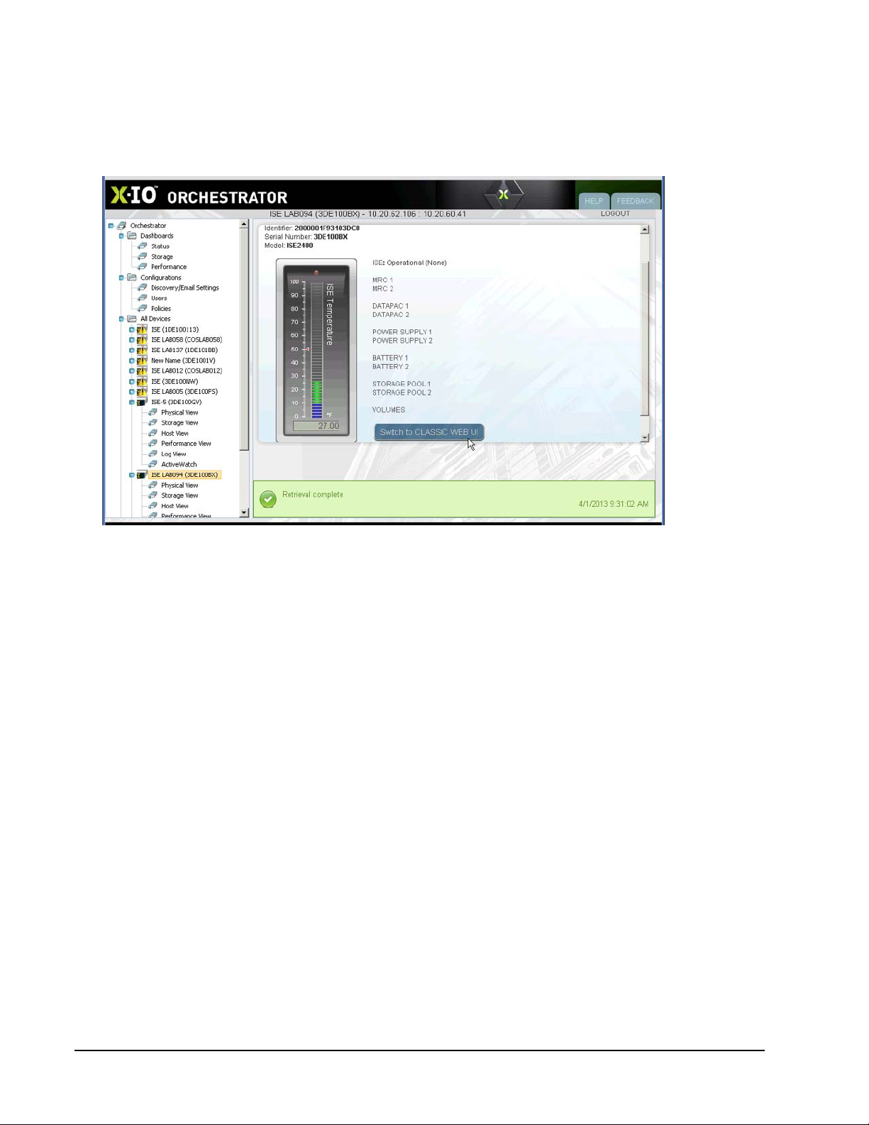
ISE User Guide Initialize and Configure
Orchestrator
Connect and log into an ISE using Orchestrator. The monitored ISEs are listed in the left navigation pane in the
form of a navigation tree. Select an ISE and the status summary (Figure 33) is displayed in the details pane.
The
Current Status
User Guide for complete details.
is shown adjacent to and at the top of the temperature gauge. Refer to the Orchestrator
Figure 33. Status Summary—Orchestrator
This view includes most of the information seen on the
At-A-Glance Status Summary
view of the classic Web-
Mgt interface. Clicking on any of the ISE components listed to the right of the temperature gauge loads the
Physical View
view. From the
for the selected ISE and tabs to properties for that component clicked on the
Physical View
, click the
Maintenance
tab. From the
Maintenance
tab click
Initialize ISE
Status Summary
(see
Orchestrator User Guide).
Page 42 160337-000 Rev D, 30 September, 2013 Xiotech—Proprietary
Page 51
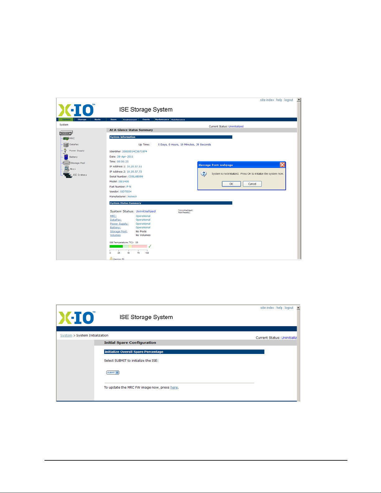
Initialize and Configure ISE User Guide
Web-Mgt
Connect to the ISE using the Web-Mgt (“Web-Based Management” on page 29 for details). After login (firsttime) to an un-initialized ISE, the
on page 103). The
Uninitialized. The
Current Status
System is Not Initialized
shown in Figure 34 on page 43.
At-A-Glance Status Summary
view is presented (see “ISE System Monitoring”
, shown in the upper right-hand corner of all views, shows Current Status:
dialog appears over the At-A-Glance Status Summary view as
Figure 34. Status Summary—Web-Mgt, System Not Initialized
The System is not initialized dialog cannot be bypassed; the only accepted actions are:
a. Click
b. Click
Figure 35. Initial Spare Configuration
OK
. The Initial Spare Configuration view appears as shown in Figure 35 below.
Cancel
. Return to the ISE login, and the browser can be closed by clicking
Close.
Xiotech—Proprietary 160337-000 Rev D, 30 September, 2013 Page 43
Page 52

ISE User Guide Initialize and Configure
From the Initial Spare Configuration view, the following options are available:
a. Initialize the ISE and the storage pools.
b. Update the ISE firmware. This option is used by a network administrator installing a new ISE and must
upgrade the firmware to the latest version before any configuration of that ISE. See “MRC Firmware
Upgrade” on page 129 for details on the upgrade process.
Initialize Storage Pools
The Initialize
Storage Pools
option would likely be used by a storage manager configuring the ISE for use on
this site. See “Storage Pools and Volumes” on page 55 for details on the set-up of storage pools and see
“Configuring Storage” on page 55 for an overview of the concept of ISE storage pools,.
While navigation away from the Initial Spare Configuration page (Figure 35) is disabled, click the browser’s
Back
button to return to the System is not in itialized. Press OK... confirmation pop-up.
To initialize storage pools, perform the following steps:
1. On the Initial Spare Configuration page (Figure 35 on page 43), click
SUBMIT
to initialize storage pools and
sparing on the DataPacs.
2. Click
OK
to the confirmation message Please wait during ISE initialization.
The message disappears and the Initial Spare Configuration view continues to display the message Sys-
tem initializing. Please wait....
3. Wait while the storage pools are initialized.
This process can take several minutes, during which the Initial Spare Configuration view remains displayed.
When pool initialization is complete, the ISE At-A-Glance Status Summary view appears and the Current
Status in the upper right-hand area of the view reports Current Status: Operational.
4. Select
Environment
>>
DataPac
to confirm that the sparing percentage of 20% is in effect on an initialized
system (see “DataPac Detailed” on page 113).
Update ISE Firmware
After ISE initialization, MRC firmware updates are applied as detailed in “ISE Firmware Upgrades” on
page 129. To update MRC firmware prior to system initialization, perform the following steps:
1. On the
igate to the
Page 44 160337-000 Rev D, 30 September, 2013 Xiotech—Proprietary
Initial Spare Configurat ion
Upload / Upgrade Firmware
view (Figure 35 on page 43), click
view shown below (Figure 36).
here
in
T o up date the MRC FW...
to nav-
Page 53
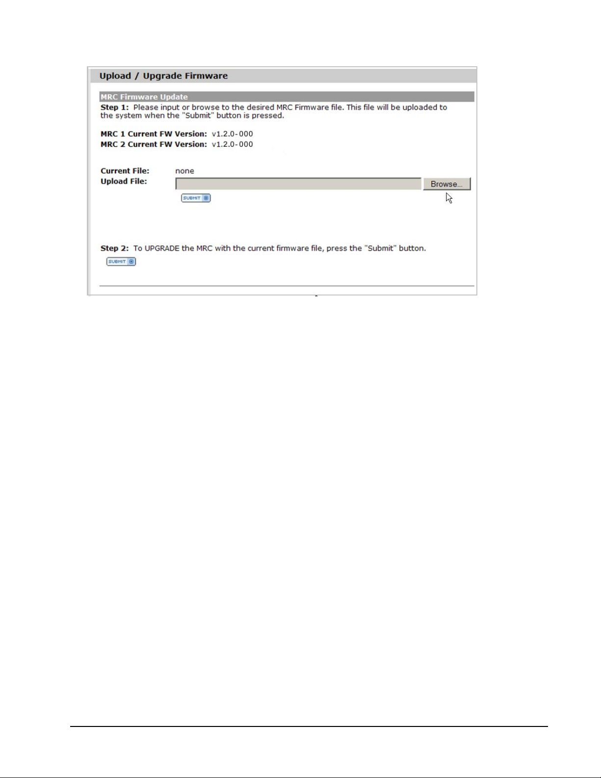
Initialize and Configure ISE User Guide
Figure 36. Upload–Upgrade Firmware
2. To perform the update, follow the procedure detailed in “MRC Firmware Upgrade” on page 129; to skip the
upgrade and return to the
Initial Spare Configuration
view, click the browser’s
Back
button.
Factory State Reset
An initialized ISE can be returned to a partial factory-ship state using the uninitialize (
A
Reformat ISE
clears all ISE volume and host configurations, rendering inaccessible any user data on the
resident DataPacs. The process to uninitialize the system is detailed in “Reformat an ISE” on page 142.
Orchestrator User Guide (“Reformat an ISE”), “Web-Mgt” on page 43, and “Command Line Interface (CLI)” on
page 45 describe initializing the ISE using the Web-Mgt and CLI respectively. For more information on the
concept of storage pools, see “Storage Pools and Volumes” on page 55.
Reformat ISE
) operation.
Command Line Interface (CLI)
Connect to the ISE using the remote console (see “Command Line Interface” on page 35 for details). At firsttime login to the un-initialized ISE, the ISE requires initialization dialog is presented in the remote
console window.
To skip the initialization process, press the
Initialize ISE and Storage Pools
To initialize the ISE and storage pools from the initialization prompt:
1. Press y and then press
Enter
.
E
SC
key. The Skipping initialization message appears.
2. The following message is displayed while initialization is occurring:
Initializing ISE (Sparing = 20%)
When initialization is complete, the word Done is displayed after the three dots in the Initializing
message, and the console returns to the prompt.
Xiotech—Proprietary 160337-000 Rev D, 30 September, 2013 Page 45
Page 54

ISE User Guide Initialize and Configure
The ISE 7-Series is initialized with one pool distributed across two DataPacs. To initialize the ISE and the
storage pools after skipping the initialization prompt, use the initialize command with no parameters.
View the sparing percentage in effect on a system that has already been initialized by using either of the
following commands:
•Type initialize. The console displays the following message:
Already initialized. Nothing to do. (Sparing = 20%).
•Type show datapac. The resulting console output includes the spare level in effect.
Page 46 160337-000 Rev D, 30 September, 2013 Xiotech—Proprietary
Page 55
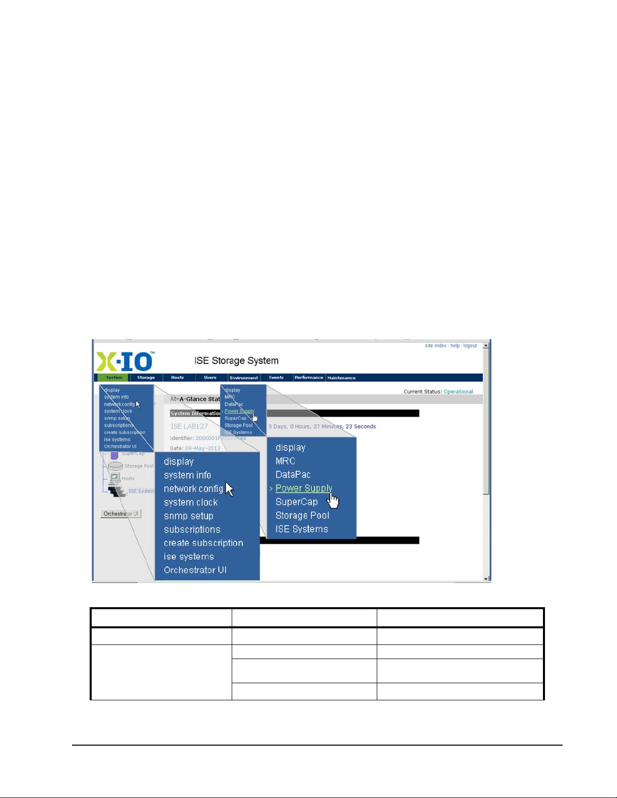
Initialize and Configure ISE User Guide
System Parameters
The configurable ISE system parameters—factory settings—should be reviewed and changed as needed.
Discussed here are:
• Using the Orchestrator interface, detailed in the Orchestrator User Guide
• Using the Web-Mgt interface as detailed in “Web-Mgt” on page 47
• Using the Command Line Interface as detailed in “Command Line Interface (CLI)” on page 45
• Explained in “ISE System Parameters Detailed” on page 49
Orchestrator
Refer to the
Orchestrator User Guide
to see what ISE system parameters can be viewed and changed
through Orchestrator.
Web-Mgt
The system parameters may be changed at any time. With the Web-Mgt, all parameter changes become
effective immediately upon clicking
connect to the ISE using the Web-Mgt. Then perform the following steps:
1. Place the pointer over the
one of the system parameter setup options from the drop-down menu as shown in Figure 37.
SA VE CHANGES
System
tab in the navigation bar in the ISE Management window and then select
(see Step 3 below). To view or set system parameters,
Figure 37. Web-Mgt Interface—System Drop-Down Menu
Setup Menu Options Parameters Description
System >> display
System >> network config
Xiotech—Proprietary 160337-000 Rev D, 30 September, 2013 Page 47
At-A-Glance Summary
DHCP setting “Network Settings” on page 51
Port 1 & 2 IP Address, IP Mask, IP
Gateway, Connection Status
Wake-on-LAN setting
“ISE System Monitoring” on page 103
“Network Settings” on page 51
“Wake-on-LAN (WOL) Service” on page 51
Page 56

ISE User Guide Initialize and Configure
Setup Menu Options Parameters Description
System Name “System Name” on page 49
Address “Address” on page 50
Syste> m >system info
System >> network config
System >> system clock
System >> snmp setup
System >> subscriptions
System >> create subscription
Environment >> MRC
Environment >> SuperCap
Table 12: Setup Menu Options
Location “Location” on page 50
Contact Name “Contact Name” on page 50
Contact Phone “Contact Phone” on page 50
Contact Email “Contact Email” on page 51
DHCP setting “Network Settings” on page 51
Port 1 & 2 IP Address, IP Mask, IP
Gateway, Connection Status
Wake-on-LAN setting “Wake-on-LAN (WOL) Service” on page 51
Date, Time, Time Zone, and enable/
disable auto-adjustment for Daylight
time
Contact Info “SNMP Contact Settings” on page 54
MIB File “Event Subscriptions” on page 54
Event Subscriptions “Event Subscriptions” on page 54
SNMP Trap Destination Setup “SNMP Trap Destination Setup” on page 54
N/A N/A
N/A N/A
Fibre Channel port speed “Fibre Channel Port Speed” on page 52
N/A N/A
“Network Settings” on page 51
“System Clock Settings” on page 52
2. Supply or change the required settings to customize the system parameters for this ISE.
3. Click
SAVE CHANGES
near the bottom of the data content area.
The view refreshes.
4. Hover the pointer over the
Environment
item on the navigation bar and select the
MRC
option from the
drop-down list to view the Fibre Channel Port Speed setting.
Fibre Channel Port Speed is described in “Fibre Channel Port Speed” on page 52.
5. Expand the selection box and click the appropriate speed.
6. Click
SAVE CHANGES
in the Global MRC FC Speed Setting section of the data content area.
Command Line Interface (CLI)
The system parameters may be changed at any time. With the CLI, all parameter changes become effective
immediately upon entry (see Step 2 below).
To set system parameters, connect to the ISE using the remote console (see “Command Line Interface” on
page 35 for details). Then perform the following steps:
1. From the prompt, set or change the system parameters using the syntax shown in Table 13 on page 49.
For example, to set the System Name, enter configure --name=<ise_systemname>, where
<ise_systemname> is the name to be associated with the ISE. Text strings with embedded blanks must
be enclosed in quotes.
2. Press
E
NTER
.
The console window displays the updated parameter list.
Page 48 160337-000 Rev D, 30 September, 2013 Xiotech—Proprietary
Page 57

Initialize and Configure ISE User Guide
3. Continue to set parameters until all desired changes are complete (use the up arrow key to retrieve previous entries).
Parameters Displayed Through the
show ise
Command
Parameter
System Name
Address
Location
Contact Name
Contact Phone
Contact Email
Fibre Channel Port Speed
Date, Time, Time Zone, and
auto-adjust for Daylight ti
me
Parameters Displayed Through the
DHCP setting
Port 1 IP Address, IP Mask, IP
Gateway, Connection Status
Port 2 IP Address, IP Mask, IP
Gateway, Connection Status
Wake-on-LAN setting
Command to Set
configure --name=<System_Name> “System Name” on page 49
configure --address=<Address> “Address” on page 50
configure --location=<Location> “Location” on page 50
configure --contact=<Contact_Name> “Contact Name” on page 50
configure --phone=<Contact_Phone> “Contact Phone” on page 50
configure --email=<Contact_Email> “Contact Email” on page 51
configure --fcspeed=<Auto|2|4|8> “Fibre Channel Port Speed” on
configure --date=<DD-MMM-YYYY>
configure --time=<HH:MM:SS>
configure --timezone=<Zone>
Also see: help timezone
configure --dhcp=<Enable|Disable> “Network Settings” on page 51
configure --ipaddress1=<x.x.x.x>
configure --netmask1=<x.x.x.x>
configure --gateway1=<x.x.x.x>
configure --ipaddress2=<x.x.x.x>
configure --netmask2=<x.x.x.x>
configure --gateway2=<x.x.x.x>
configure --wol=<Enable|Disable> “Wake-on-LAN (WOL) Service” on
1
show network
Additional Description
page 52
“System Clock Settings” on page 52
2
Command
“Network Settings” on page 51
“Network Settings” on page 51
page 51
Table 13: CLI—System Parameters
1
Entries may contain special characters except those listed in “Reserved Characters” on page 35. If an entry
is to include spaces, enclose the entire entry in quotation marks.
2
Append the --dst option to this command to specify automatic adjustment to Daylight Savings Time.
ISE System Parameters Detailed
This section describes the various system parameters of the ISE that can be customized.
System Name
The system name is an optional user-defined name for an ISE. A name is any alphanumeric string of up to
thirty-two characters. Embedded blanks and special characters (excepting “Reserved Characters” on page 35)
are permitted.
Web-Mgt Interface: To view or set the System Name from the Web-Mgt, select the System Information
Settings view (
navigation pane.
CLI: To display the System Name from the CLI, use the show ise command. The System Name is changed
with the configure --name=<ise_system_name> command (“CLI—System Parameters” ). If the name
is to contain embedded blanks, enclose the character string in quotation marks as shown in the following
example:
configure --name=<“ISE System Name”>
System
>>
system info
). A name applied to an ISE is shown adjacent to the ISE icon in the
Xiotech—Proprietary 160337-000 Rev D, 30 September, 2013 Page 49
Page 58

ISE User Guide Initialize and Configure
Address
The Address is an optional user-defined address for an ISE, defining a physical address, building, or any
address string. The address is any alphanumeric string of up to sixty characters. Embedded blanks and special
characters (excepting “Reserved Characters” on page 29) are permitted.
Web-Mgt: To view or set the Address from the Web-Mgt, select the System Information Settings view (
>>
system info
).
System
CLI: To display the Address from the CLI, use the show ise command. To set the Address from the CLI, use
the configure --address=<ise_address> command (see Figure 13 on page 49). If the address is to
contain embedded blanks, enclose the character string in quotation marks as shown in the following example:
configure --address=<“ISE Address”>
Location
The Location is an optional user-defined location for an ISE, such as a data center, room number, rack
number, rack position, or any other type of locator. The location is any alphanumeric string of up to sixty
characters. Embedded blanks and special characters (excepting “Reserved Characters” on page 29) are
permitted.
Web-Mgt: To view or set the Location from the Web-Mgt, select the
>>
system info
).
System Information Settings
view (
System
CLI: To display the Location from the CLI, use the show ise command. To set the Location from the CLI, use
the configure --location=<ise_location> command (see Figure 13 on page 49). If the location is to
contain embedded blanks, enclose the character string in quotation marks as shown in the following example:
configure --location=<“ISE location”>
Contact Name
The Contact Name is an optional user-defined name for a person associated with this ISE, such as a storage
manager, network administrator, or other associated person. The contact name is any alphanumeric string of
up to sixty alphanumeric characters. Embedded blanks and special characters (excepting “Reserved
Characters” on page 29) are permitted.
Web-Mgt: To view or set the Contact Name from the Web-Mgt, select the System Information Settings view
(
System
>>
system info
).
CLI: To display the Contact Name from the CLI, use the show ise command. To set the Contact Name from
the CLI, use the configure --contact=<contact_name> command (see Figure 13 on page 49). If the
contact name is to contain embedded blanks, enclose the character string in quotation marks as shown in the
following example:
configure --contact=<“contact name”>
Contact Phone
The Contact Phone is an optional user-supplied phone number for the contact person (see “Contact Name” on
page 50). The contact phone is any alphanumeric string of up to sixteen characters. Embedded blanks and
special characters (excepting “Reserved Characters” on page 29) are permitted.
Web-Mgt: To view or set the Contact Phone from the Web-Mgt, select the System Information Settings view
(
System
>>
system info
).
Page 50 160337-000 Rev D, 30 September, 2013 Xiotech—Proprietary
Page 59

Initialize and Configure ISE User Guide
CLI: To display the Contact Phone from the CLI, use the show ise command. To set the Contact Phone
from the CLI, use the configure --phone=<contact_phone> command (see Figure 13 on page 49). If
the contact phone is to contain embedded blanks, enclose the character string in quotation marks as shown in
the following example:
configure --phone=<“contact phone”>
Contact Email
The Contact Email is an optional user-defined e-mail address for the contact person (see “Contact Name” on
page 50). The Contact Email field accepts any valid e-mail address of up to sixty alphanumeric characters.
Web-Mgt: To view or set the Contact Email from the Web-Mgt, select the System Information Settings view
(
System
>>
system info
).
CLI: To display the Contact Email from the CLI, use the show ise command. To set the Contact e-mail from
the CLI, use the configure --mail=<contact_email> command (see Figure 13 on page 49) as shown
in the following example:
Network Settings
The ISE Network Settings include two Ethernet ports (1 and 2), the Media Access Control (MAC) address, link
status (connected or unknown), and Dynamic Host Configuration Protocol (DHCP) mode (enabled or
disabled). Connections to the Web-Mgt and the CLI are made through the Ethernet ports.
When DHCP mode is enabled, the network DHCP server assigns an IP address, mask, and gateway to each
of the Ethernet ports. These addresses are displayed by the Web-Mgt and the CLI as the
Port 1
and
Port 2
addresses and cannot be set when DHCP mode is enabled. The ISE enables DHCP Mode by default.
When DHCP mode is disabled, the IP address, mask, and gateway for
Port 1
and
Port 2
must be supplied at
system setup time and manually changed to reflect any network changes that have an impact.
Web-Mgt: To view or change the network settings from the Web-Mgt, select the Network Settings view (
>>
system network
).
System
CLI: To display the network settings from the CLI, use the show network command. To set the IP address,
netmask, and gateway from the CLI, use the syntax shown in “CLI—System Parameters” on page 49. To set
the DHCP Mode from the CLI, use the configure --dhcp=<Enable|Disable> command (see Figure 13
on page 49).
Wake-on-LAN (WOL) Service
The setting of the Wake-on-LAN (WOL) Service controls the means by which the ISE is activated after being
placed into standby mode by the system shutdown as follows:
• If WOL is enabled, the Ethernet ports monitor the network for a magic packet sent to the ISE by certain
third-party utilities to restart it remotely. The ISE enables WOL by default.
• If WOL is disabled, the Ethernet ports do not monitor the network for a magic packet. To restart the ISE,
toggle the rocker switches of both power supplies
are in the off position concurrently for a minimum of five seconds.
OFF
and ON, ensuring that the switches on both supplies
See “Power-up, Shutdown, Restart” on page 37 for more information about system powerup, shutdown, and
restart.
Web-Mgt: To view or change the WOL setting from the Web-Mgt, select the Network Settings view (
network config
Xiotech—Proprietary 160337-000 Rev D, 30 September, 2013 Page 51
).
System
>>
Page 60

ISE User Guide Initialize and Configure
CLI: To display the WOL setting from the CLI, use the show network command. To set the WOL Mode from
the CLI, use the configure --wol=<Enable|Disable> command (see Figure 13 on page 49).
System Clock Settings
During ISE manufacture, the system clock is set to Coordinated Universal Time (UTC). If desired, the Web-Mgt
or CLI, as described in this section, can be used to manually set the system clock as needed to meet site
requirements. When the system clock is set on one MRC, the system clock of the companion MRC is
automatically and immediately synchronized.
To approximately synchronize the ISE to a local server manually, enter a synchronization time and wait for the
server’s clock to cycle to that synchronization time before clicking
E
NTER
while in the CLI.
Orchestrator: To set or change the system clock using the Orchestrator, select
Physical View
>>
System Clock
. (See the Orchestrator User Guide.)
Save Changes
in the Web-Mgt or pressing
All Devices
>>
ise_name
>>
Web-Mgt: To set this parameter from the Web-Mgt, select the System Clock Setup view (
clock
).
System
>>
system
CLI: To set this parameter from the CLI, use the configure command with the options shown in “CLI—
System Parameters” on page 49.
The following formats apply to both the Web-Mgt and the CLI:
a. Date: dd-mmm-yyyy, where mmm is the 3-letter representation of a month (for example, Nov for Novem-
ber). Enter the month in uppercase or lowercase or a combination of both; it is displayed in lowercase with
an initial capital.
b. Time: hh:mm:ss using a 24-hour clock.
c. Time Zone:
• In the Web-Mgt, a drop-down menu provides the time zone selections.
• In the CLI, type help timezone to see the time zone options.
d. Daylight: Enable this option to cause the ISE to automatically adjust the time for the change to and from
Daylight Savings Time. The Daylight option is enabled by default.
System Clock Attribute CLI Command
Date
Time
Timezone
Automatic Daylight
Time
configure --date=<dd-mm-yyyy>
configure --time=<hh:mm:ss>
configure --timezone=<zoneoption>
configure --timezone=<zoneoption>
configure --timezone=<zoneoption> --dst
Use
help timezone
view options
To disable
To enable
to
Table 14: Setting System Clock Attributes—CLI Commands
Fibre Channel Port Speed
The Fibre Channel host port speed can be set to one of the following settings:
• ISE-2, Hyper ISE, and ISE 7-Series: Speeds of 4 and 8 Gbs are supported on the individual ports when
specified otherwise all ports are the same, Fibre Channel activity occurs at the selected speed (see
support matrix at www.X-IO.com).
• Auto: Using the protocol defined in the T11 Auto-Negotiation standard, the ISE auto-negotiates with the
Fibre Channel switch to determine and set the highest port speed that both devices support.
• Auto-negotiation is enabled by default at the factory.
Page 52 160337-000 Rev D, 30 September, 2013 Xiotech—Proprietary
Page 61

Initialize and Configure ISE User Guide
Web-Mgt: This parameter is accessed using the Web-Mgt through the
Environment >> MRC
option as
described in Step 4 of “Setup Menu Options” on page 48.
CLI: To control this parameter using the CLI, use the configure --fcspeed=<Auto|1|2|4> command
(see “CLI—System Parameters” on page 49).
UPS Mode
While the ISE has no data connection for UPS hardware, the ISE should be powered through an
uninterruptible power supply (UPS) to maintain power to cache memory in the event of a power outage. By
default, the ISE disables UPS Mode. If the ISE is protected by a UPS, enable UPS mode by setting the
Mode
system parameter to
Orchestrator: To enable or disable the UPS Mode with Orchestrator select this path:
>>
Physical View
then click the
Web-Mgt: The UPS Mode parameter is accessed using the Web-Mgt through the
Enable
.
UPS Mode Selected
check box.
All Devices
Environment
>>
>>
UPS
ISE_Name
Battery
option as described in “Supercapacitor Detailed” on page 115.
CLI: To enable or disable UPS Mode using the CLI, use the configure --upsmode=<Enable|Disable>
command (see “Command Line Interface (CLI)” on page 45).
SNMP Setup
The ISE has a number of configurable SNMP settings as well as fixed factory settings. SNMP V1 and V2 are
supported by the ISE, and the SNMP protocol data units (PDUs) are implemented. In addition, the ISE includes
an algorithm to prevent denial of service attacks.
SNMP PDU ISE Support Status Notes
GetRequest
GetNextRequest
Response
SetRequest
GetBulkRequest
InformRequest
TrapV2
Report
T able 15: SNMP PDUs Implementation
Yes ISE monitors port 161
Yes ISE monitors port 161
No —
No ISE is set through the Web-Mgt or the CLI
Yes ISE monitors port 161
No —
Yes ISE sends on port 162
No —
Configuring SNMP
SNMP contact information, MIB root OID, Event subscriptions, and SNMP trap destination IP address are the
configurable SNMP settings. The SNMP Contact parameters are detailed below in “SNMP Contact Settings”
through “SNMP Trap Destination Setup” on page 54.
Monitoring the ISE using SNMP Object Identifiers is described in “System Monitoring with SNMP” on
page 120.
Xiotech—Proprietary 160337-000 Rev D, 30 September, 2013 Page 53
Page 62

ISE User Guide Initialize and Configure
Web-Mgt: The SNMP settings, contact information, and MIB root OID are accessible through the Web-Mgt
only. To customize these parameters, use the procedures detailed in “Web-Mgt” on page 47, selecting
setup
from the
any time. All changes become effective immediately after clicking
System
drop-down menu shown in Figure 37 (page 47). SNMP parameters may be changed at
SAVE CHANGES
at the bottom of the view.
snmp
SNMP Contact Settings
The information entered in the four SNMP Contact settings is included in the Management Information Base
(MIB) file for the ISE and in SNMP GetRequest and Trap notification packets. The SNMP Contact information
settings are:
• Community string
•Contact information
• Organization
• Description
MIB Root OID Setting
The ISE Root OID Name and Number are also displayed.
When any change to the four Contact Information parameters is saved by clicking
SUBMIT
or
SAVE CHANGES
the system automatically regenerates the MIB file to include the new information.
Event Subscriptions
Event subscriptions provide the means to designate which events are to be forwarded to the SNMP Client
Application. Upon an event, the system checks this list to determine whether to send the event as an SNMP
trap to the SNMP Trap Destination list (see “SNMP Trap Destination Setup” this page). SNMP traps are
datagrams and do not have guaranteed delivery. Traps are sent only once and are not saved locally. Event
subscriptions are configured from the Web-Mgt only; they cannot be configured from the CLI.
To subscribe, select events from the
Selected Subscriptions
list. Use the
Available Subscriptions
C
TRL
or
S
HIFT
keys while clicking to select multiple events.
list and then click
Add
to move them into the
The Web-Mgt displays the Available Subscriptions and Selected Subscriptions lists for each Network Port on
the ISE (one port for each MRC). These subscription lists are independent and should be selected for both
ports. To obtain consistency in trap generation between the two MRCs, it is advisable to subscribe to the same
events on both Network Ports.
Trap service is provided by one of the two MRCs; if the trap-serving MRC experiences an exception causing a
reboot, the surviving MRC resumes trap service using only the traps and destinations defined for itself. Traps
defined only for an out-of-service MRC are not sent by the surviving MRC. Should trap service need to be
restarted on the surviving MRC, some traps may be lost during the transition.
SNMP Trap Destination Setup
,
The SNMP trap destination setup allows specification of site-specific IP addresses to which the selected
SNMP events (see “Event Subscriptions” ) are sent. Events can be sent to different IP addresses from each
port if desired. Duplicate IP addresses are not permitted in the address lists and cannot be added.
Web-Mgt: SNMP trap destinations are configurable from the Web-Mgt only; they cannot be configured from
the CLI. To set up the SNMP trap destinations, follow these steps for each network port:
1. Enter an SNMP trap destination IP address in the Enter Address field.
2. Click
Page 54 160337-000 Rev D, 30 September, 2013 Xiotech—Proprietary
NEW
to move the address from the Enter Address field to the Address List.
Page 63

Initialize and Configure ISE User Guide
3. If necessary, select addresses in the Address List for deletion or editing:
• To delete an address from the Address List, select it and click
lines).
• To edit an address in the Address List, select it and click
Address
modified address appears in the Address List, replacing the previous address.
4. Repeat Step 1 through Step 3 until the address lists are complete.
field, where it can be changed as needed. Click
DELETE
EDIT
. The address appears in the
NEW
when the address is correct; the
(
C
TRL
or
S
HIFT
fort multiple
Enter
5. When both lists are complete, click
ing the new settings.
SAVE CHANGES
at the bottom of the view. The view refreshes, reflect-
CLI: SNMP Trap Settings
In the CLI, only Trap Subscriptions and Destinations can be modified.
To subscribe to and unsubscribe from SNMP trap notifications, use the trap_subscription command as
follows.
trap_subscription network={1|2} {add|remove} events="n,m,o,p"
where 1 or 2 identifies the MRC that will originate the trap and where n,m,o,... are the event numbers.
To the SNMP trap notification destination, use the trap_destination command as follows.
trap_destination network={1|2} {add|remove} address="n,m,o,p"
where n,m,o,... are IP addresses.
MIB File
The Web-Mgt provides a link to the Management Information Base (MIB) file for the ISE. This file can be
viewed or downloaded to be compiled into an SNMP device-monitoring tool using the on-screen instructions.
The ISE automatically regenerates the MIB file when changes to any logical object in the system are made,
ensuring that the MIB file is always current. Monitoring the ISE using SNMP Object Identifiers is described in
“System Monitoring with SNMP” on page 120.
Configuring Storage
This section provides an overview of ISE storage and its configuration using the Web-Mgt and the CLI.
“Creating Volumes” on page 58 and “Command Line Interface” on page 60 detail the procedures to create
volumes using the Web-Mgt and the CLI respectively.
Storage Pools and Volumes
In the ISE, storage capacity is organized into entities called storage pools. A storage pool consists of all
available storage in one DataPac, or, in the case of an ISE 7-Series, a single storage pool consists of all
available storage in both DataPacs. The overall capacity of each pool is determined by the type of DataPac
and the percentage of capacity reserved for sparing during initialization of the storage pools (see “Initializing
ISE” on page 41).
Each storage pool can be segmented into multiple volumes. Volumes within a storage pool can be of any RAID
type supported by the ISE and can have a maximum capacity of 2 TB each with mirroring and 8 TB each
without mirroring. Sparing and RAID operations occur within the boundaries of the storage pool. Volumes are
created in the ISE on a pool-by-pool basis, and the cache policy (write-back or write-through) and RAID type
are specified on a volume.
Xiotech—Proprietary 160337-000 Rev D, 30 September, 2013 Page 55
Page 64
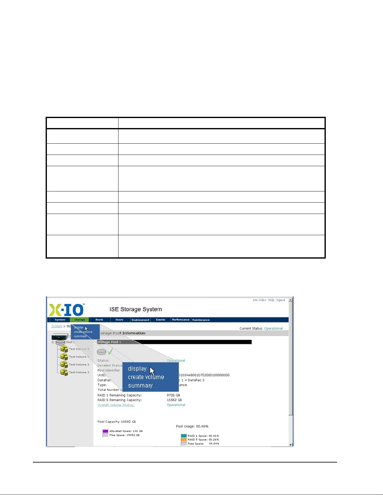
ISE User Guide Initialize and Configure
The Orchestrator interface (see the Orchestrator User Guide) provides storage pool management through the
following select strings:
1.
All Devices
2.
All Devices
3.
All Devices
>>
>>
>>
ise_name
ise_name
ise_name
>>
Storage View
>>
Storage View
>>
Storage View
>>
Storage Pools
>>
Volumes
>>
Mirrors
The Web-Mgt interface provides a Storage Pool Information view (see Figure 38 on page 57), accessed by
placing the cursor over the
Storage
tab and selecting
display
from the drop-down menu. In this view, the
characteristics listed below are shown for each storage pool.
Characteristic Description
Status
Detailed Status
Pool identifier
Type
Number Volumes Pool
Remaining Capacity
Overall Volume Status
Pool Stats
Overall state of the storage pool. This field usually reports Operational. Other possible
states include Uninitialized or Non-Operational.
Reports any unusual state the pool may be in. This field usually reports None.
Equivalent to DataPac number.
Performance DataPac
Balanced DataPac
Capacity DataPac
Number of volumes assigned to the identified pool.
Remaining capacity by RAID type.
Reports the overall state of the volumes within the storage pool. If any volumes in the pool
are non-operational, this status reports Non-Operational. Click this link to select the Volume
Summary view (see Figure 41 on page 59).
Pool capacity (raw GB used vs. free)
Pool usage (total percentage of pool used, percentage used for each RAID type, and percentage free)
Table 16: Storage characteristics
Storage Pool Information panels display a list of all volumes in the pool as shown below. This view is also
reached by expanding the pool tree element in the navigation pane of many of the Management Information
panels.
Page 56 160337-000 Rev D, 30 September, 2013 Xiotech—Proprietary
Page 65
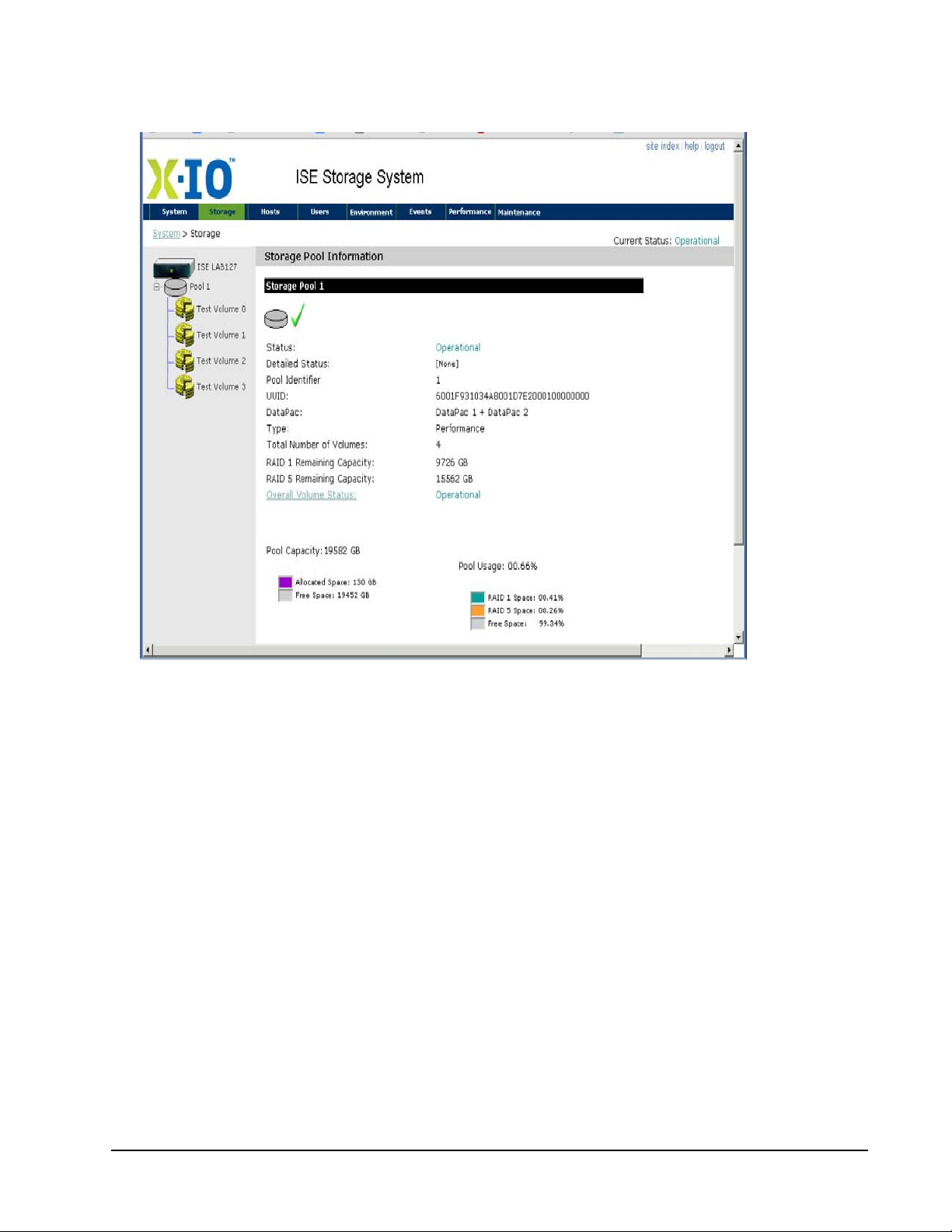
Initialize and Configure ISE User Guide
Figure 38. Web-Mgt—ISE-2 Storage Pool Information
Figure 39. Web-Mgt—ISE 7-Series Storage Pool Informa t ion
From the CLI, obtain storage pool information using the show pool command.
Xiotech—Proprietary 160337-000 Rev D, 30 September, 2013 Page 57
Page 66
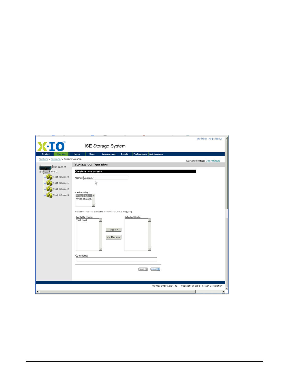
ISE User Guide Initialize and Configure
Creating Volumes
This section details the steps to create volumes using the Web-Mgt and the CLI.
Orchestrator
To create volumes using the Orchestrator, select
click
ADD V
OLUME
. (See the Orchestrator User Guide.)
All Devices
>>
ise_name
>>
Storage View
>>
Volumes
Web-Mgt
To create volumes using the Web-Mgt, follow the steps below.
Note. Cache policy, volume-host mapping, LUN number, and volume size can be modified after the
volume is created.
1. Place the pointer over the
2. Select
create volume
Storage
tab on any Web-Mgt panel and the Storage drop-down menu appears.
from the menu options to change to the Storage Configuration view as shown below
(Figure 40).
then
Figure 40. Web-Mgt—Storage Configuration
3. Enter an alphanumeric string of up to thirty-two characters for the volume being created in the Name field.
The name cannot begin with a numeric character and may contain special characters except those listed in
“Command Line Interface (CLI)” on page 45.
4. Select the cache policy (
Write-Back
or
Write-Through
) for this volume.
5. From the available pools, select the RAID level and size, where the remaining capacity is included with the
RAID type. A selected RAID level’s remaining capacity is displayed in the
Page 58 160337-000 Rev D, 30 September, 2013 Xiotech—Proprietary
Capacity in Gigabytes
field.
Page 67
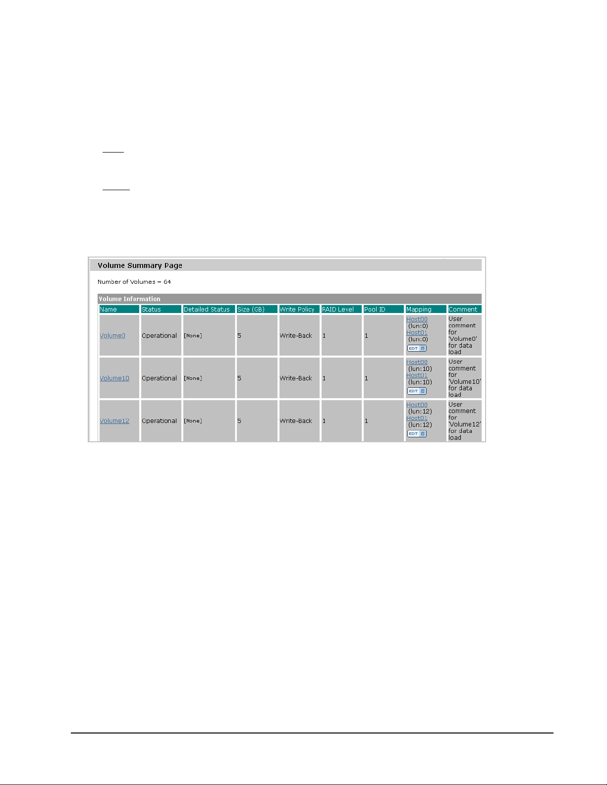
Initialize and Configure ISE User Guide
6. If the volume is not intended to consume the remaining capacity shown in the
Capacity in Gigabytes
field,
enter the intended capacity for the volume being created.
If no hosts have been created, no entries appear in the
Available Hosts
list. Hosts can be mapped to vol-
umes during the host-creation process (see “Configuring Hosts” on page 60).
7. Enter volume information in the optional
Comment
field that accepts up to sixty alphanumeric characters,
including special characters except those listed in “Command Line Interface (CLI)” on page 45.
8. To clear
volume data entered since the last
SUBMIT
, click
RESET
.
The view restores the most recently saved settings.
9. To create
The
Volume Summary
the volume as defined, click
appears (see Figure 41), showing all existing volumes with their host mappings. See
SUBMIT
.
“View, Modify LUNs” on page 85 for more information about LUNs.
10. To create additional volumes, repeat Step 1 through Step 9 in this procedure until all desired volumes have
been created.
Figure 41. Volume Summary
Xiotech—Proprietary 160337-000 Rev D, 30 September, 2013 Page 59
Page 68

ISE User Guide Initialize and Configure
Volume 'Payroll' (RAID= 1, Size= 100 GB, Pool= 2, Cache= Write-Back)
Creation started successfully.
Command Line Interface
To create volumes using the Command Line Interface (CLI), follow the steps below.
Note. Cache mode, volume-host mapping, LUN number, and volume size can be modified after the
volume is created.
To view the remaining capacity for volumes of each RAID type within each pool, type show pool. Then locate
the Free Capacity section of the resulting console display.
To create a volume using the CLI, use the create volume command with the options shown in Table 17. If
a name is not specified, the CLI auto-generates a name in the format Volumenn, where nn is an incrementing
number starting from
Command Options Comment
create --volume=<name>
or
create --volume
01
. Any auto-generated names that already exist are skipped over.
--size=<size in GB>
--raid1
--pool1
--pool2
--write-back or --wb
--write-through or --wt
--comment=<comment text>
Volume size in GB
RAID 1 volume (default)
Volume from Pool 1 (default)
Volume from Pool 2
Write-back cache policy (default)
Write-through cache policy
Optional comment
Example:
create --volume=Payroll --size=100 --raid1 --pool2 --wb --comment=”Pay Roll”
Table 17: Create Volume Command—CLI
The example command in Table 17 creates a RAID1 volume named Payroll of 100GB from storage pool 2 with
write-back caching and the comment Pay Roll.
The volume name may be up to thirty-two alphanumeric characters long (but may not begin with a numeric
character). The comment may be up to sixty alphanumeric characters long. Special characters are accepted
except those listed in “Command Line Interface (CLI)” on page 45. Text strings with embedded blanks must be
enclosed in quotes as shown in the above example.
The ISE creates the volume and displays a confirmation like that shown in the figure below.
Figure 42. Volume Created Confirmation—CLI
Configuring Hosts
In the ISE, Host Bus Adapter (HBA) port World Wide IDs (WWIDs) are organized into entities called hosts. A
host consists of one or more HBAs under a single name, by which all the HBAs in the host are referenced.
Hosts may contain HBA ports from different host computer systems. Hosts allow convenient mapping of
storage volumes to the HBAs by providing recognizable named entities containing multiple HBAs.
A list of the HBAs by WWID that comprise a given host can be viewed by expanding the host tree element in
the navigation pane of many of the Management Information panels.
Page 60 160337-000 Rev D, 30 September, 2013 Xiotech—Proprietary
Page 69
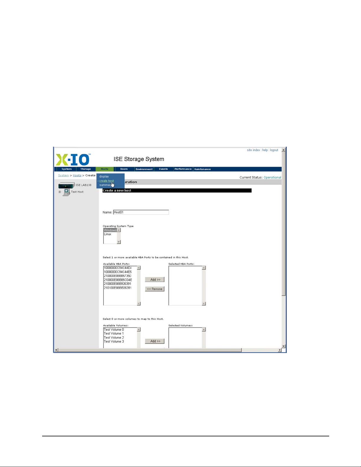
Initialize and Configure ISE User Guide
Creating Hosts
Creating hosts using the Web-Mgt and the CLI is detailed in “Web-Mgt” below and “Command Line Interface
(CLI)” on page 63 respectively. LUN assignments can be changed using the
default luns assignments (see Figure 59 on page 87).
Note. When creating hosts on an ISE not connected to the target hosts, use the CLI interface (page 63).
Orchestrator
E
DIT
Web-Mgt interface to avoid
To create hosts through Orchestrator, select
H
OST
. (See the Orchestrator User Guide.)
Web-Mgt
1. Select
Hosts
>>
create host
opens as shown below.
from the navigation bar on the Web-Mgt and the
All Devices
>>
ise_name
>>
Host View
>>
Host
then click
Host Configuration
ADD
screen
Figure 43. Host Configuration
2. In the Name field, enter a unique alphanumeric string up to thirty-two characters long for the host being
created. The name cannot begin with a numeric character and may contain special characters except
those listed in “Reserved Characters” on page 29.
3. Select the operating system type for this host.
4. Select the HBA ports to be contained in this host from the
WWIDs that the ISE detected on the network. Use
Xiotech—Proprietary 160337-000 Rev D, 30 September, 2013 Page 61
C
Available HBA Ports
TRL
or
S
HIFT
list containing all HBA port
to select multiple WWIDs.
Page 70
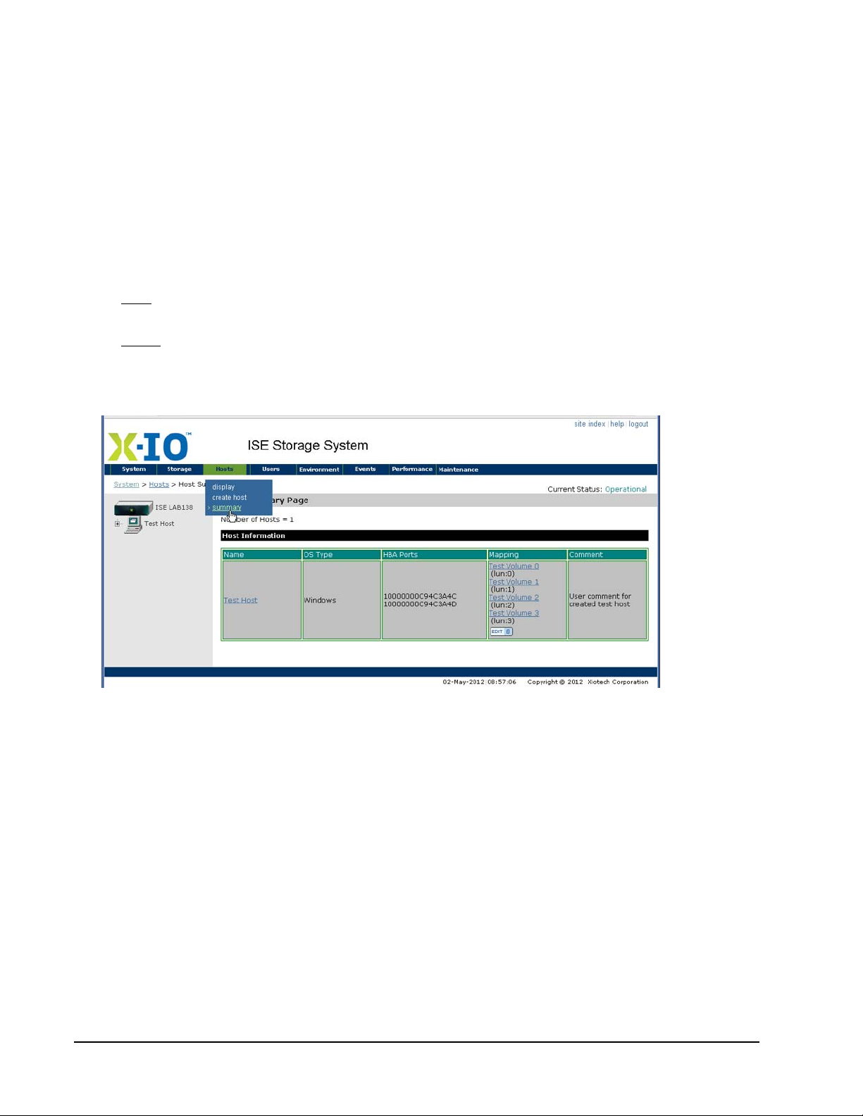
ISE User Guide Initialize and Configure
5. Click
6. Select the volumes to map to this host from the
7. Click
Add
to add the selected HBA ports to the Selected HBA Ports list. The host consists of the ports in
the Selected HBA Ports list after
Add
to add the selected volumes to the
C
TRL
or
S
HIFT
keys while clicking
SUBMIT
Add
is clicked.
Available Volumes
Selected Volumes
.
If no volumes have been created, no entries appear in the
list.
list. To select multiple volumes, use the
Available Volumes
list. Volumes can be mapped
to hosts during the volume-creation process (see “Mapping Volumes and Hosts” on page 64).
8. Enter comment text as needed in the optional Comment field. The comment may be up to sixty alphanumeric characters long. Special characters are accepted except those listed in “Reserved Characters” on
page 29.
9. To clear
volume data entered since the last
SUBMIT
, click
RESET
and the view restores the most recently
saved settings.
10. To create
the host as defined, click
SUBMIT
and the
Host Summary
appears (see Figure 44), showing all
existing volumes with their host mappings.
11. To create additional hosts, repeat Step 1 through Step 10 in this procedure until all desired hosts have been created.
Figure 44. Host Summary
Page 62 160337-000 Rev D, 30 September, 2013 Xiotech—Proprietary
Page 71

Initialize and Configure ISE User Guide
GEN01 (Windows)
---------------------------------------------------------------------- Comment : Test_Host_1
HBAs : 10000000D94D0123, 10000000A87D0902
Volumes : <no volumes presented to this host>
----------------------------------------------------------------------Host created
Command Line Interface (CLI)
To create a host using the CLI, use the create host command with the options shown in Table 18. To see
a list of assigned and unassigned HBA port WWIDs, enter the show hba command. If a name is not
specified, the CLI auto-generates a name in the format Hostnn, where nn is an incrementing number starting
from
01
. Any auto-generated names that already exist are skipped over.
Command Options Comment
--windows
create --host=<name>
or
create --host
create --host=GEN01 --windows 10000000D94D0123 10000000A87D0902 --comment= ”Test
Host 1”
Table 18: Create Host Command
--linux
--comment=<comment text>
<list of HBA WWNs that
compose this host>
Example:
The example command in Table 18 creates a host named GEN01 with a Windows operating system and
containing HBA port WWIDs 10000000D94D0123 and 10000000A87D0902 and comment Test Host 1.
For host using Windows operating system.
This option is the default
For host using Linux operating system.
Optional comment.
Separate multiple HBA WWIDs with spaces.
.
The host name may be up to thirty-two alphanumeric characters long but may not begin with a numeric
character. The comment may be up to sixty alphanumeric characters long. Special characters are accepted
except those listed in “Reserved Characters” on page 29. Text strings with embedded blanks must be
enclosed in quotes as shown in the example.
The ISE creates the host and displays a confirmation similar to that shown in the figure (45) below.
Figure 45. Host Created Confirmation
Volumes and hosts are mapped with the CLI using the present command. See “Command Line Interface
(CLI)” on page 64 for details.
Xiotech—Proprietary 160337-000 Rev D, 30 September, 2013 Page 63
Page 72

ISE User Guide Initialize and Configure
Mapping Volumes and Hosts
This section details mapping volumes and hosts using the Web-Mgt and the CLI. When presenting a volume to
a host, a mapping between that host and that volume is created. Each time a mapping is made, the ISE
assigns an incrementing LUN number (starting with 0) for the volumes seen by that host. For example, if
volume04 is the first volume mapped to Host01, the mapping LUN number assigned to this host is LUN0.
Volume04 could also be the second volume mapped to Host02, where it would be assigned to Host02 as
LUN1. An assigned LUN number can be changed for a given volume on a given host as needed to meet the
site host/LUN configuration requirements.
Orchestrator
To map hosts and volumes through Orchestrator, select
click
ADD H
OST
. (See the Orchestrator User Guide.)
All Devices
>>
ise_name
>>
Host View
>>
Host
then
Web-Mgt
Volumes and hosts can be mapped from several operations in the Web-Mgt:
• During volume creation as described in “Creating Volumes” on page 58
• During host creation as described in “Creating Hosts” on page 61
• By editing volumes or hosts from the Volume or Host Detailed Information views as described in “Volume
and Host Configuration” on page 75
Mappings are displayed in the
>>
summary
). After the initial volume-host mapping scheme is created, mappings can be deleted and modified
Volume Summary
view (
Storage>>summary
) and Host Summary view (
Hosts
at any time using several Web-Mgt operations detailed in “Modify Volume–Host Mappings” on page 82.
Command Line Interface (CLI)
To map volumes and hosts through the CLI, use the present command with the options shown in Table 19.
Command Options Comment
<host name>
present --volume=<name>
:<LUN number>
<volume name>
present --host=<name>
:<LUN number>
Examples:
present --volume=Volume7 Host00:8 Host01:5
present --host=Host00 Volume07:8 Volume02:4
Hosts to be mapped to this volume. Separate multiple
hosts with spaces.
Optional entry to specify the LUN on which this host is to
see this volume. Place this option immediately after the
host name
Volumes to be mapped to this host. Separate multiple volumes with spaces.
Optional entry to specify the LUN on which this volume is
to be presented to this host. Place this option immediately
after the volume name.
maps Volume7 to Host00 as LUN8 and to Host 01 as
LUN5.
maps Host00 to Volume7 on LUN8 and to Volume2 on
LUN4.
.
Table 19: Present Command
For example, the command below presents
Volume03
to hosts
Prod01
and
Prod02
without specifying the LUN.
present --volume=Volume03 Prod01 Prod02
Page 64 160337-000 Rev D, 30 September, 2013 Xiotech—Proprietary
Page 73

Initialize and Configure ISE User Guide
Presenting 'Volume03' to 'Prod01': OK
Presenting 'Volume03' to 'Prod02': OK
The ISE creates the mapping and displays a confirmation similar to that shown in the figure (46) below.
Figure 46. Volume Host Mapping
After the initial volume-host mapping scheme has been created, it can be modified or deleted at any time using
the CLI commands detailed in “Modify Volume–Host Mappings” on page 82.
Xiotech—Proprietary 160337-000 Rev D, 30 September, 2013 Page 65
Page 74

ISE User Guide Initialize and Configure
Page 66 160337-000 Rev D, 30 September, 2013 Xiotech—Proprietary
Page 75

ISE Management ISE User Guide
ISE Management
This chapter details the various aspects of managing an ISE configuration:
• System and SNMP settings (“Modify System, SNMP” on page 67)
• ISE Analyzer (“ISE Analyzer Software Service” on page 68 and “Subscription Function” on page 68)
• Volumes and Hosts (“Volume and Host Configuration” on page 75)
• Volume–Host mapping (“Modify Volume–Host Mappings” on page 82)
• LUNs (“View, Modify LUNs” on page 85)
• Expand and Contract LUNs (“View, Modify LUNs” on page 85)
• Volume Cache policy (“Re-size LUNs” on page 88)
• Volume Delete (“Deleting Volumes” on page 91)
• Host Delete (“Deleting Hosts” on page 91)
• ISE Systems Dashboard (“ISE Systems Dashboard” on page 92)
Modify System, SNMP
Orchestrator: To modify the System parameters using Orchestrator, follow the procedures detailed in the
Orchestrator User Guide.
Web-Mgt: To modify the system information and SNMP settings using the Web-Mgt:
1. Select the setup views by choosing the desired option from the
“Web-Mgt Interface—System Drop-Down Menu” on page 47.
2. Make the desired changes.
3. Click
CLI: To modify the System parameters using the CLI, follow the procedures detailed in “Command Line
Interface (CLI)” on page 48. All changes become effective immediately after
The SNMP settings cannot be set or changed from the Orchestrator or the CLI.
SAVE CHANGES
changes.
at the bottom of the view. All changes become effective immediately after saving the
System
drop-down menu as detailed in
ENTER
is pressed.
Xiotech—Proprietary 160337-000 Rev D, 30 September, 2013 Page 67
Page 76

ISE User Guide ISE Management
ISE Analyzer Software Service
The optional
time status, configuration, and performance data from multiple ISEs. The
ISE Analyzer Software Service
executes on an appliance, providing a single point for viewing real-
ISE Analyzer Software Service
consists of a dedicated server running a Web-based application that collects and displays the following types
of data:
• General Updates: This data contains extensive information about the ISE, including the state of FRUs,
performance data, volume status, and configuration
• Telemetry data: This data contains SMART logs, CEL files, and system logs
• Alerts: Notifications of specific events site-selected to track and notify a monitoring destination
The
ISE Analyzer Software Service
real time. ActiveWatch delivers diagnostic information to
works in conjunction with ActiveWatch by monitoring ActiveWatch data in
X-IO
Customer Support (Support) collects daily
performance data that is automatically sent to Support through secure web service calls, and sends system
alerts to
An
Analyzer Software Service
X-IO
to expedite issue resolution.
ISE Analyzer Software Service
managed by Support can be used.
can be installed locally and used to access ActiveWatch data, or the
ISE
Subscription Function
The ISE includes the
Service
Analyzer Software Service
managed by Support.
destinations can be defined:
• ISE Analyzer Software Service, managed by Xiotech, is built into the ISE as the default
and with the subscription function disabled
using either the ISE Web Interface (Web-Mgt) or the Command Line Interface (CLI).
• Local ISE Analyzer: Up to three addresses are supported through the Web-Mgt and the CLI.
Subscription
function that is used to adjust the IP address of the
Subscription
is also used to provide an IP address for a locally installed
ISE Analyzer Software
to which General Update files, Telemetry files, and alerts can be sent. The following
destination
. Subscription to this destination can be enabled or disabled
ISE
Each subscription entry has three components:
• IP address: The IP address of the destination, expressed in IPv4-standard format
(nnn.nnn.nnn.nnn:ppp) or DNS name.
• Interval: The number of minutes between one data transmission and the next. The default interval is
1440 minutes (24 hours); the interval range is from 15 to 1440 minutes. Alerts are sent as they occur
regardless of the interval set for data transmission.
• Enabled/disabled state: Each subscription entry can be individually enabled or disabled for
transmission. General Updates, Telemetry data, and alerts are sent to all
enabled addresses.
Web Interface
These Web interfaces can be used in relation to the
•
X-IO
Orchestrator can be used to manage subscriptions.
ISE Analyzer Software Service
:
• ISE Web-Mgt can be used to manage subscriptions.
• ISE Analyzer
web interface is used to configure, manage subscriptions, and view ActiveWatch data. Refer to
the ISE Analyzer User Guide for more information.
• ISE Manager, an add-on.
Command Line Interface
The Command Line Interface (CLI) can be used to manage subscriptions. When using the CLI, enter the
command help subscribe for help with subscription commands.
Page 68 160337-000 Rev D, 30 September, 2013 Xiotech—Proprietary
Page 77
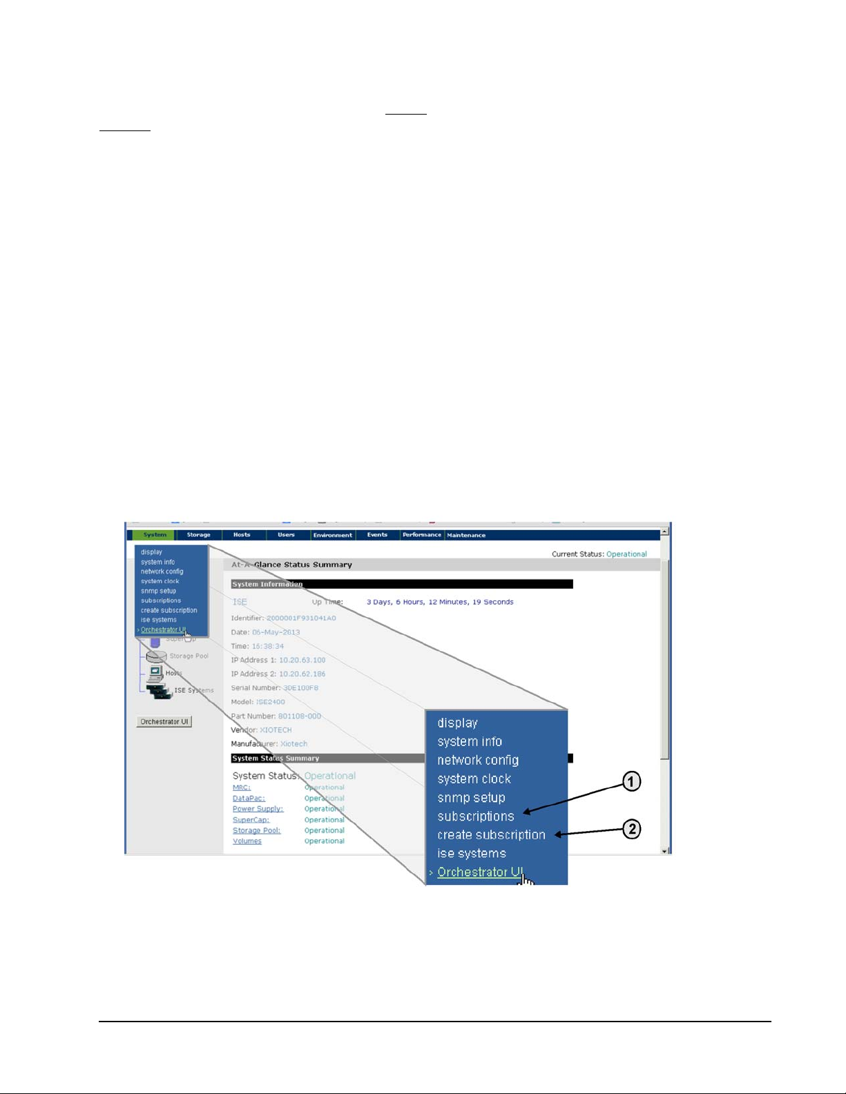
ISE Management ISE User Guide
Enable Subscriptions
The
ISE Analyzer Software Service
disabled
. To use the
ISE Analyzer Software Service
secure SSL connection.
ships with a default destination address and the subscription function
, subscription must be enabled. This destination uses a
When enabling a subscription to the
ISE Analyzer Software Service
, it may be necessary to configure the site
firewall to allow outbound HTTPS communication (port 443 using TCP). To precisely specify the destination,
define the target address as 207.250.72.215—this restricts other HTTPS traffic.
Notes:
[1] The interval for Telemetry and General Update subscriptions can be specified, but Alert subscriptions can-
not be specified.
[2] When creating or changing Telemetry update subscriptions, it is recommended that the interval be left at
1440. If a smaller interval is specified, the ISE can run out of resources and log the following event in the
SMGT event log:
General Telemetry request for <host> has failed with status code = 4 - No resources
Orchestrator
To manage ActiveWatch subscriptions using the Orchestrator, select
>>
Subscriptions
. (See the Orchestrator User Guide.)
All Devices
>>
ise_name
>>
ActiveWatch
Web-Mgt Interface Using the Web Interface At-A-Glance Summary Page, pull down the System menu and select create
subscription as shown in Figure 47 below (reference number 2).
Figure 47. Subscription Function
Xiotech—Proprietary 160337-000 Rev D, 30 September, 2013 Page 69
Page 78
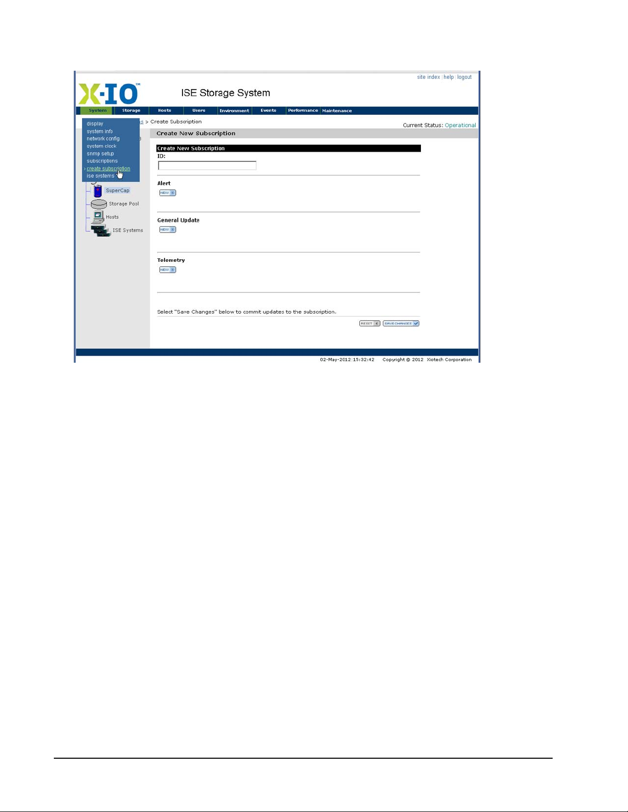
ISE User Guide ISE Management
The Create New Subscription page is displayed as shown in Figure 48.
Figure 48. Enable ISE Analyzer Service Subscription
Subscribing:
1. Enter an
2. Click
3. Click
4. Click
5. Click
ISE Analyzer Software Service
A
LERT
to subscribe to Alerts.
G
ENERAL UPDATES
T
ELEMETRY
S
AVE CHANGES
to subscribe to Telemetry.
to subscribe to General Updates.
and the subscription is complete.
IP address.
Command Line Interface
From the CLI, enter the following command at the prompt:
subscribe add -ipaddress=207.250.72.215 -type=gupdate -interval=720 -enabled=true
The range for the -interval option is 15 to 1440 minutes. For Telemetry it is recommended that the interval
be allowed to default to 1440.
Enable Local Subscriptions
The Web-Mgt manipulates the
Software Service
Service
by entering the following command at the prompt:
subscribe add -ipaddress=nnn.nnn.nnn.nnn:ppp [-enabled=true|false] -type=type
[-interval=xx]
subscriptions. Use the CLI to define a subscription to a locally installed
ISE Analyzer Softwar e Servi ce
managed by Xiotech as well as local
ISE Analyzer Software
ISE Analyzer
where
nnn.nnn.nnn.nnn:ppp
in IPv4-standard format and the
Page 70 160337-000 Rev D, 30 September, 2013 Xiotech—Proprietary
is the IP address and port of the local
type
is
alert, gupdate
, or
telemetry
ISE Analyzer Software Service
.
expressed
Page 79
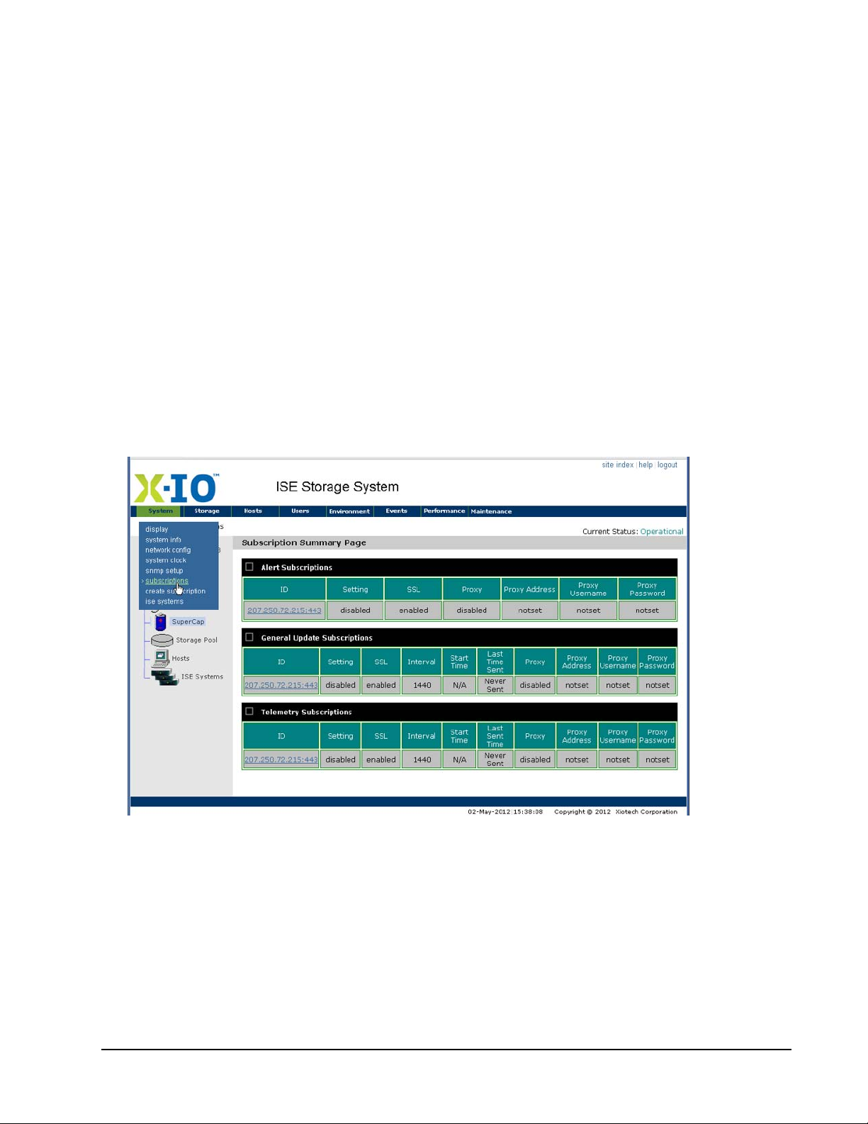
ISE Management ISE User Guide
The range for the -interval option is 15 to 1440 minutes. For Telemetry it is recommended that the interval
be allowed to default to 1440.
For example, the following command creates a subscription with an IP address destination of 10.20.30.40 and
an interval of 8 hours (720 minutes).
subscribe add -ipaddress=10.20.30.40 -interval=720
View Subscriptions
Active subscriptions can be viewed with the Orchestrator, the Web-Mgt interface, and the CLI.
Orchestrator
To view ActiveWatch subscriptions using the Orchestrator, select
Subscriptions
. (See the Orchestrator User Guide.)
All Devices
>>
ise_name
>>
ActiveWatch
>>
Web-Mgt
From Web-Mgt At-A-Glance Summary Page, pull down the System menu and select subscriptions (see
Figure 47 on page 69, reference number 1). The Subscription Summary Page appears, showing the IP
address of the default subscription to the ISE Analyzer Software Service managed by Xiotech (Figure 49
below).
Figure 49. Subscription Summary
Command Line Interface
From the CLI, enter the following command at the prompt to view a subscription to a locally installed ISE
Analyzer Software Service:
subscribe show
The existing subscriptions are displayed similar to the following example:
ipaddress=10.20.30.40, type=telemetry enabled=true, interval=1440
Xiotech—Proprietary 160337-000 Rev D, 30 September, 2013 Page 71
Page 80

ISE User Guide ISE Management
Modify Subscription
The interval for Telemetry and General Update subscriptions can be modified. Alert subscriptions do not have
an interval.
Notes:
[1] The interval for Telemetry and General Update subscriptions can be modified, but Alert subscription inter-
vals cannot be modified.
[2] When creating or changing Telemetry update subscriptions, it is recommended that the interval be left at
1440. If a smaller interval is specified, the ISE can run out of resources and log the following event in the
SMGT event log:
General Telemetry request for <host> has failed with status code = 4 - No resources
Orchestrator
To modify ActiveWatch subscriptions using the Orchestrator, select
>>
Subscriptions
. (See the Orchestrator User Guide.)
All Devices
>>
ise_name
>>
ActiveWatch
Web-Mgt
To modify a subscription through the Web Interface:
1. Enter an
2. Click
3. Click
4. Click
ISE Analyzer Software Service
A
LERT
to change an Alert subscription.
G
ENERAL UPDATES
T
ELEMETRY
to change a Telemetry subscription.
to change a General Updates subscription.
IP address or DNS name.
5. When prompted, enter the appropriate change.
6. Click
AVE CHANGES
and the subscription modification is complete.
S
Command Line Interface
To modify a subscription with the CLI, use the subscribe add command with new settings for enabled or
interval. The subscription is modified with the settings included on the command line. In the following
example, the interval of a subscription to IP address 10.20.30.40 is changed from 1440 minutes to 720
minutes.
subscribe show
10.20.30.40:443, type=telemetry, enable=true, interval=1440, Last Sent= 14-Sep-2010
09:17:26
10.20.30.40:443, type=general update, enable=true, interval=1440, Last Sent= 14-Sep2010 09:17:26
10.20.30.40:443, type=alert, enable=true
subscribe add -ipaddress=10.20.30.40 -type=gupdate, -interval=720
subscribe show
10.20.30.40:443, type=telemetry, enable=true, interval=1440, Last Sent= 14-Sep-2010
09:17:26
10.20.30.40:443, type=general update, enable=true, interval=720, Last Sent= 14-Sep-2010
09:17:26
10.20.30.40:443, type=alert, enable=true
Page 72 160337-000 Rev D, 30 September, 2013 Xiotech—Proprietary
Page 81

ISE Management ISE User Guide
Disable Subscriptions
Once a subscription to
ISE Analyzer Software Service
has been enabled, it can be disabled using either the ISE
Web Interface or the CLI as described below.
Orchestrator
To disable ActiveWatch subscriptions using the Orchestrator, select
>>
Subscriptions
. (See the Orchestrator User Guide.)
All Devices
>>
ise_name
>>
ActiveWatch
Web Interface From the Web Interface At-A-Glance Summary Page, pull down the System menu and select
Create
subscription (see Figure 47 on page 69). The Subscription Setup Page is displayed, showing the IP
address of a subscription (see Figure 49 on page 71). To un-subscribe:
1. Enter an
2. Click
3. Click
4. Click
5. Click
Note. Do not try to delete a subscription by deleting the IP address in the
ISE Analyzer Software Service
A
LERT
to un-subscribe from Alerts.
G
ENERAL UPDATES
T
ELEMETRY
S
AVE CHANGES
to un-subscribe from Telemetry.
to un-subscribe from General Updates.
and the un-subscription is complete.
IP address.
Address
box. The Web Interface
does not save changes (including un-checking any check box) if the IP address field is blank.
Command Line Interface
From the CLI, enter the following command at the prompt:
subscribe add -ipaddress=nnn.nnn.nnn.nnn -type=type -enabled=false
where
format and the
nnn.nnn.nnn.nnn
type
is
alert, gupdate
is the IP address of the
, or
telemetry
ISE Analyzer Software Service
expressed in IPv4-standard
. The range for the -interval option is 15 to 1440
minutes. For example, to disable the general update subscription to 207.250.72.215:443, enter
subscribe add -ipaddress=207.250.72.215:443 -type=gupdate -enabled=false
Delete Subscriptions
To delete a subscription, enter the following command at the prompt:
subscribe delete -ipaddress=nnn.nnn.nnn.nnn:ppp -type=type
where
format and the
For example, to delete the general update subscription to 10.20.30.40:443, enter
nnn.nnn.nnn.nnn
type
subscribe show
10.20.30.40:443, type=telemetry, enable=true, interval=1440, Last Sent= 14-Sep2010 09:17:26
10.20.30.40:443, type=general update, enable=false, interval=720, Last Sent= 14Sep-2010 09:17:26
10.20.30.40:443, type=alert, enable=true
subscribe delete -ipaddress=10.20.30.40:443 type=telemetry
subscribe show
is the IP address of the
is
alert, gupdate
, or
telemetry
ISE Analyzer Software Service
.
expressed in IPv4-standard
Xiotech—Proprietary 160337-000 Rev D, 30 September, 2013 Page 73
Page 82

ISE User Guide ISE Management
10.20.30.40:443, type=general update, enable=false, interval=720, Last Sent= 14Sep-2010 09:17:26
10.20.30.40:443, type=alert, enable=true
Send General Update File
An immediate transmission of the General Update file to the
Support or the locally installed
ISE Analyzer Software Service
ISE Analyzer Software Service
managed by
can be directly initiated through the CLI. The
General Update file contains extensive information about the ISE, including state of FRUs, performance data,
volume status and configuration, and more. The transmission uses a secure SSL operation. This function is
available in the CLI and indirectly through Orchestrator (see Orchestrator User Guide) only.
Orchestrator
To initiate immediate transmission of the General Update file select
>>
Maintenance
>>
Send CLI Command
and then send:
gupdate send [-ipaddress=nnn.nnn.nnn.nnn]
As described below.
All Devices
>>
ise_name
>>
Physical View
CLI
To initiate immediate transmission of the General Update file, enter the following command at the CLI prompt:
gupdate send [-ipaddress=nnn.nnn.nnn.nnn]
where nnn.nnn.nnn.nnn is the IP address of the local
standard format.
The -ipaddress option may be omitted if the desired destination is the default IP address (the
Software Service
managed by Support). If a different address is desired, define it with the ipaddress option.
For example:
ISE Analyzer Software Service
expressed in IPv4-
ISE Analyzer
gupdate send sends General Update file to the default address.
gupdate send -ipaddress=10.20.30.40 sends General Update file to 10.20.30.40.
Send Telemetry Data File
An immediate transmission of a Telemetry data file to the
the locally installed
ISE Analyzer Software Service
can be directly initiated through the CLI. Telemetry data files
contain SMART logs, CEL file, system logs, and more. The transmission uses a secure SSL operation. This
function is available in the CLI and indirectly through Orchestrator (see Orchestrator User Guide).
ISE Analyzer Software Service
managed by Support or
Orchestrator
To initiate immediate transmission of the General Update file, select
>>
Maintenance
>>
Send CLI Command
and then send:
telemetry send [-ipaddress=nnn.nnn.nnn.nnn]
As described in the following CLI example.
All Devices
>>
ise_name
>>
Physical View
Page 74 160337-000 Rev D, 30 September, 2013 Xiotech—Proprietary
Page 83

ISE Management ISE User Guide
CLI
To initiate immediate transmission of the Telemetry data file, enter the following command at the CLI prompt.
telemetry send [-ipaddress=nnn.nnn.nnn.nnn]
where nnn.nnn.nnn.nnn is the IP address of an
format. The -ipaddress option can be omitted if the intention is to send telemetry to all
Service
subscriptions. If a specific
ISE Analyzer Software Service
ISE Analyzer Software Service
is desired, select it with the -ipaddress
expressed in IPv4-standard
ISE Analyzer Software
option. For example:
telemetry send sends the Telemetry file to all
ISE Analyzer Software Service
subscriptions.
telemetry send -ipaddress=10.20.30.40 sends the Telemetry file to 10.20.30.40.
X-IO
Note. Do not use the telemetry send -file unless instructed to by
Customer Support.
Volume and Host Configuration
Orchestrator
To view ISE volume configuration by pools using the Orchestrator, select
View
>>
Storage Pools
. (See the Orchestrator User Guide.)
Web-Mgt, View Volumes
To view ISE volume configurations by pools, open the
1. Open the
Volume Summary
view by placing the pointer over the
2. Expand the Pool navigation trees in the left navigation pane (shown in Figure 50 below).
Detailed Volume Information
All Devices
Storage
>>
ise_name
page as follows:
tab and selecting
>>
summary
Storage
.
3. Open the
expanded pool navigation tree or in the first column of the
Detailed Volume Information
page by clicking on the volume name (ref. 1 in Figure 50) in the
Volume Information
of the page.
When volume-host mappings exist, hosts mapped to the volumes are shown in the
V o lu me Information
section.
(ref. 2 in Figure 50) section
Mapping
column of the
Xiotech—Proprietary 160337-000 Rev D, 30 September, 2013 Page 75
Page 84
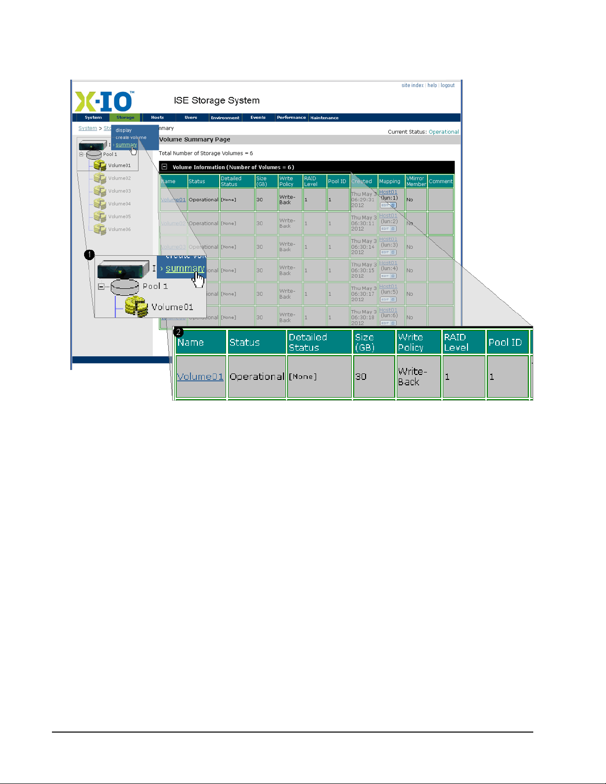
ISE User Guide ISE Management
The
Detailed V olume Information
Information
section below (see reference 2 in Figure 50).
page appears with the volume names in the first column of the
Volume
Figure 50. Detailed Volume Information
Web-Mgt, Modify Volume
To modify volume configurations, open the
view the following modifications can be made to a volume:
• Change the volume name
• Change the cache policy
• View the pool, the RAID level, the capacity, the Global ID, and the Local ID of the volume
• Add and remove volume-host mapping schemes as detailed in “Modify Volume–Host Mappings” on
page 82
• Create or change a volume comment
• Delete a volume by selecting it and clicking
• Add and remove host mappings
Note. A volume cannot be deleted with an active host mapping. Mappings can be removed through the
Available Hosts
and
Selected Hosts
options in this view.
Detailed Volume Information
Delete
(bottom of the view)
view (Figure 51 on page 77). From this
Page 76 160337-000 Rev D, 30 September, 2013 Xiotech—Proprietary
Page 85
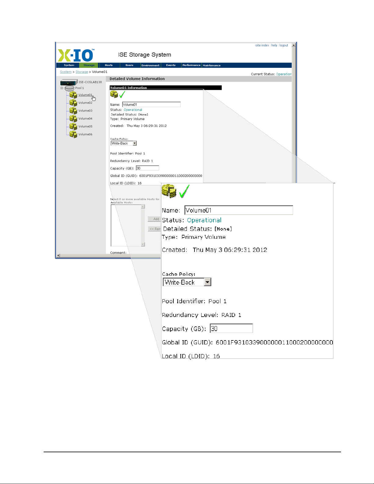
ISE Management ISE User Guide
Changes do not take effect until
Save Changes
(bottom of the view) is clicked.
Figure 51. Detailed Volume Information
Orchestrator, View Host Configuration
To view ISE host configuration using the Orchestrator, select
(See the Orchestrator User Guide.)
Xiotech—Proprietary 160337-000 Rev D, 30 September, 2013 Page 77
All Devices
>>
ise_name
>>
Host View
>>
Host
.
Page 86
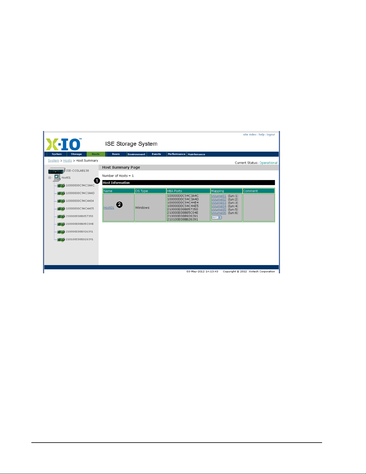
ISE User Guide ISE Management
Web-Mgt, View Host Configuration
To view ISE host configurations, open the
1. Select
Hosts
>>
summary
from the navigation bar on any Web-Mgt page and the
Detailed Host Information
page as follows:
opens.
2. Expand the Host navigation tree in the left navigation pane.
3. Access the
Detailed Host Information
view by clicking the Host MAC ID in the expanded navigation tree
(ref. 1 in Figure 52) or the Host name in the Host Information view (ref. 2 in Figure 52).
When volume-host mappings exist, volumes mapped to the hosts are shown in the
Information
The
section.
Detailed Host Information
page is shown below in Figure 52.
Host Summary
Mapping
column of the
view
Host
Figure 52. Detailed Host Information
Orchestrator, Modify Host Configuration
To modify the ISE host configuration using the Orchestrator, select
Host
. (See the Orchestrator User Guide.)
All Devices
>>
ise_name
>>
Host View
>>
Web-Mgt, Modify Host Configuration
From the
•Host name
• Operating system type
• Create or modify the WWID HBA ports for this host; see “Configuring Hosts” on page 60
• Create or modify a volume-host mapping scheme; see “Modify Volume–Host Mappings” on page 82
• Create or modify a comment
• Delete a host by highlighting a host and clicking
Note. A host with an active volume mapping cannot be deleted; mappings can be removed using the
Available Volumes
Page 78 160337-000 Rev D, 30 September, 2013 Xiotech—Proprietary
Detailed Host Information
(see 1 below) and
page (Figure 53), the following configuration changes can be made:
Delete
at the bottom of the page
Selected Volumes
(see 2 below) section of this view.
Page 87
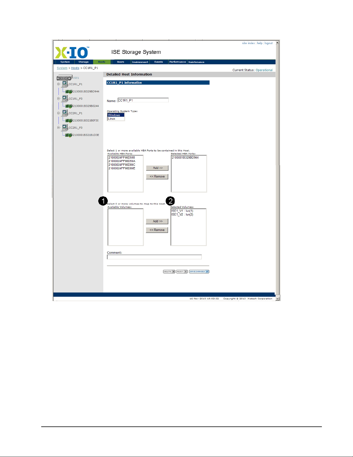
ISE Management ISE User Guide
Changes do not take effect until
Save Changes
(bottom of the view) is clicked.
Figure 53. Detailed Host Information
Xiotech—Proprietary 160337-000 Rev D, 30 September, 2013 Page 79
Page 88

ISE User Guide ISE Management
Volume7: (Pool 1, 20 GB, Raid 1, Write-Back cache)
---------------------------------------------------------------------- Status : Operational (None)
LDID : 20
GUID : 6000CA08806310002787000200000000
Comment : Transaction Volume
Hosts : GEN01(LUN:7)
-----------------------------------------------------------------------
CLI, View–Modify Volume Configuration
View existing volumes from the CLI using the show volume command.
Note. The Local ID (LDID) number provides the means to map the relevant events in the Event Log to the
name given the volume during volume creation. The LDID number for each volume is displayed below the
volume status as shown in the following example.
Figure 54. Show Volume Example
Change the volume name, cache policy, and optional comment through the CLI using the modify command
with the options shown in Table 20 below.
Command Options Comment
--name=<new name>
Change the volume name
modify --volume=<name>
--write-back or --wb
--write-through or --wt
--comment=<comment text>
Example:
modify --volume=Payroll --name=Transaction --wt --comment=”transaction volume”
Table 20: Modify Volumes
Change cache policy to write-back
Change cache policy to write-through
Change the optional comment
Page 80 160337-000 Rev D, 30 September, 2013 Xiotech—Proprietary
Page 89

ISE Management ISE User Guide
CLI, View–Modify Host Configuration
View existing hosts through the CLI using the show hosts command and existing HBA port WWIDs using the
show hba command. View any mappings by entering show hosts or show volumes.
Change the host name, its operating system, the member HBA port WWIDs, and its optional comment from the
CLI using the modify command with the options shown in Figure 21.
To remove HBA port WWIDs from the host, all mappings to that host must be removed. To do so, use the
unpresent command as described in “Modify Volume–Host Mappings” on page 82. After the host
modifications are complete, restore or create the requisite mappings using the present command as
described in the same section.
Command Options Comment
Change the host name
Change host operating system to Windows
Change host operating system to Linux
Add HBA WWID to host. Separate multiple
WWIDs with spaces.
Remove HBA WWID from host. Separate multiple WWIDs with spaces.
Change the optional comment
Modify --host=<name>
--name=<new name>
--windows
--linux
--add=<WNN>
--remove=<WNN>
--comment=<comment text>
Example:
modify --host=GEN01 --name=Prod6 --remove 10000000D94D0123 --comment= ”Rack1
Slot6”
Table 21: Modify Hosts
Xiotech—Proprietary 160337-000 Rev D, 30 September, 2013 Page 81
Page 90

ISE User Guide ISE Management
Modify Volume–Host Mappings
The volume-host mapping scheme can be modified at any time after initial configuration. The Orchestrator,
Web-Mgt, and the CLI can be used as follows:
• Modify volumes and hosts with the Orchestrator (see Orchestrator User Guide).
• Modify volumes and hosts with the Web-Mgt (see “Web-Mgt”).
• Delete mappings with the Web-Mgt (see “Delete Volume–Host Mapping”).
• Modify the volume-host mapping with the CLI (see “CLI, Modify Volume–Host Mapping” on page 84).
Orchestrator
To modify the volume–host mappings using the Orchestrator, select
Mapping
. (See the Orchestrator User Guide.)
All Devices
>>
ise_name
>>
Host View
>>
Web-Mgt
Modify the volume-host mapping scheme at any time by editing volumes or hosts. To do so, use the Detailed
Volume Information page or Detailed Host Information page as described in “Volume and Host Configuration”
on page 75.
Delete Volume–Host Mapping
Orchestrator
To delete ISE volume–host mappings using the Orchestrator, select
Mapping
. (See the Orchestrator User Guide.)
Web-Mgt
The steps involved in deleting host maps are presented in “Mapping Volumes and Hosts” on page 64. To see
mappings from the Web-Mgt, open the Volume Summary view (
view (
Host>>Summary
mappings:
1. Click the
Edit
• In the Mapping column on the
(Figure 44 on page 62)
• To the right of
page 77)
• Next to the
page 79)
). Deleting a mapping removes the visibility of the volume by the host. To delete
button in one of the following locations:
Selected Hosts
Selected Volumes
Host Summary
list-box on the
list-box on the
page (Figure 41 on page 59) or
Detailed Volume Information
Detailed Host Information
All Devices
Volume>>Summary
>>
page (shown in Figure 51 on
page (shown in Figure 53 on
ise_name
>>
Host View
) or the Host Summary
Volume Summary
page
>>
Page 82 160337-000 Rev D, 30 September, 2013 Xiotech—Proprietary
Page 91
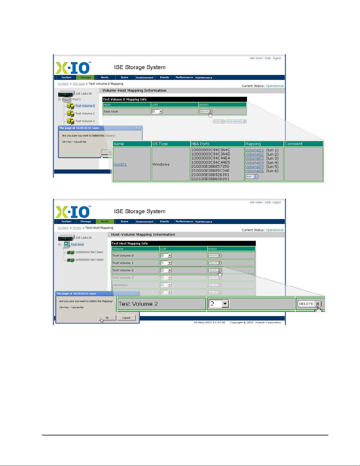
ISE Management ISE User Guide
The
Vo lume-Host Mapping Information
view (Figure 55) or the
Host-Volume Mapping Information
view
(shown in Figure 56 on page 83) appears (see “View, Modify LUNs” on page 85 for more information on
LUN mapping).
Figure 55. Volume-Host Mapping Information –Delete
Figure 56. Host–Volume Mapping Information–Delete
2. Click
3. Click
Xiotech—Proprietary 160337-000 Rev D, 30 September, 2013 Page 83
Delete
in the Action column of the mapping to be deleted and a confirmation dialog appears.
OK
to delete this mapping and end visibility of the volume by this host.
Page 92

ISE User Guide ISE Management
CLI, Modify Volume–Host Mapping
The steps involved in modifying host mappings are presented in “Mapping Volumes and Hosts” on page 64.
Deleting a mapping removes visibility from the host to the volume. The volume–host mapping scheme can be
modified at any time through the CLI by first deleting the current mapping using the unpresent command with
the options shown in Table 22. Then create a new mapping using the present command with the options
shown in Table 23.
Command Options Comment
unpresent --volume=<name>
<host name>
--all
<volume name>
unpresent --host=<name>
--all
Examples:
Host or list of hosts (separated by blanks) to be
unmapped from this volume.
Following volume name unmaps all hosts from a volume.
Volume or list of volumes (separated by blanks) to be
unmapped from this host.
Following host name unmaps all volumes from a host.
unpresent --volume=Volume7 Host00 Host01
unpresent --host=Host00 Volume07 Volume02
unpresent --host=Host00 --all
Unmaps Volume7 from Host00 and Host 01.
Unmaps Host00 from Volume7 and Volume2.
Unmaps Host 00 from all volumes.
Table 22: Unpresent Command—CLI
Command Options Comment
Hosts to be mapped to this volume. Separate multiple hosts with
spaces.
Optional entry to specify the LUN on which this host is to see this
volume. Place this option immediately after the host name.
Volumes to be mapped to this host. Separate multiple volumes
with spaces.
Optional entry to specify the LUN on which this volume is to be
presented to this host. Place this option immediately after the volume name.
present --volume=<name>
present --host=<name>
<host name>
:<LUN number>
<volume name>
:<LUN number>
Examples:
present --volume=Volume7 Host00:8
Host01:5 present --host=Host00
Volume07:8 Volume02:4
Maps Volume7 to Host00 as LUN8 and to Host 01 as LUN5.
Maps Host00 to Volume7 on LUN8 and to Volume2 on LUN4.
Table 23: Present Command
For example, assume Volume03 is mapped to hosts Prod01 and Prod02 and it needs to be mapped to hosts
Prod01 and Prod07 instead. The following sequence of commands changes the mapping as needed.
unpresent --volume=Volume03 Prod02
The mapping of Volume03 to host Prod02 is deleted and the mapping of Volume03 to host Prod01 remains
unaffected. The following message appears on the console when the unmapping completes:
Unpresenting 'Volume03' from 'Prod02':OK
The following present command creates the new mapping:
present --volume=Volume03 Prod07
Volume03 is mapped to host Prod07 and the following message appears on the console upon completion:
Presenting 'Volume03' to 'Prod07': OK
A subsequent show volume confirms that Volume03 is now mapped to hosts Prod01 and Prod07.
Page 84 160337-000 Rev D, 30 September, 2013 Xiotech—Proprietary
Page 93

ISE Management ISE User Guide
View, Modify LUNs
LUNs are created during host-volume mapping. Each time a mapping is made, the ISE assigns an
incrementing LUN number (starting with 0) to the volumes seen by that host. For example, in the configuration
shown in Figure 55 on page 83,
r2_meta1
is the first volume mapped to
cc1r2_p1_ini
, so it is
LUN0
to this host.
From the Web-Mgt, LUN assignments are displayed in the Volume Summary view (
Host Summary view (
Hosts>>summary
). In the CLI, LUN assignments are displayed on the console from the
Storage>>summary
) or
show host and show volume commands.
The LUN number for a given volume on a given host can be changed as needed to meet host-LUN
configuration requirements. The following subsections detail changing the LUN using the Web-Mgt (“Web-Mgt
View, Modify LUNs”) and the CLI (“CLI View, Modify LUNs” on page 87).
Orchestrator View, Modify LUNs
To view and modify LUNs using the Orchestrator, select
(See the Orchestrator User Guide.)
All Devices
>>
ise_name
>>
Host View
>>
Mapping
.
Web-Mgt View, Modify LUNs
From the Web-Mgt, the LUNs assigned to each volume are shown on the following pages:
•
Host Summary (Hosts>>summary
•
Vo lume Summary (Storage>>summary
•
Detailed Host Information
•
Detailed Volume Information
, click the host on the
, click the volume on the
To change a LUN assignment:
1. Click the volume name in one of the following locations:
•
Mapping
column of the
Host Summary
• Host in the left navigation pane on the
• Volume in the left navigation pane on the
) (Figure 44 on page 62)
) (Figure 41 on page 59)
Host
or
Volume Summary
Host
or
page or
Detailed Volume Information
Volume Summary
Detailed Host Information
page (Figure 53 on page 79)
Volume Summary
page
page (Figure 51 on page 77)
page (Figure 53 on page 79)
page (Figure 51 on page 77)
Xiotech—Proprietary 160337-000 Rev D, 30 September, 2013 Page 85
Page 94
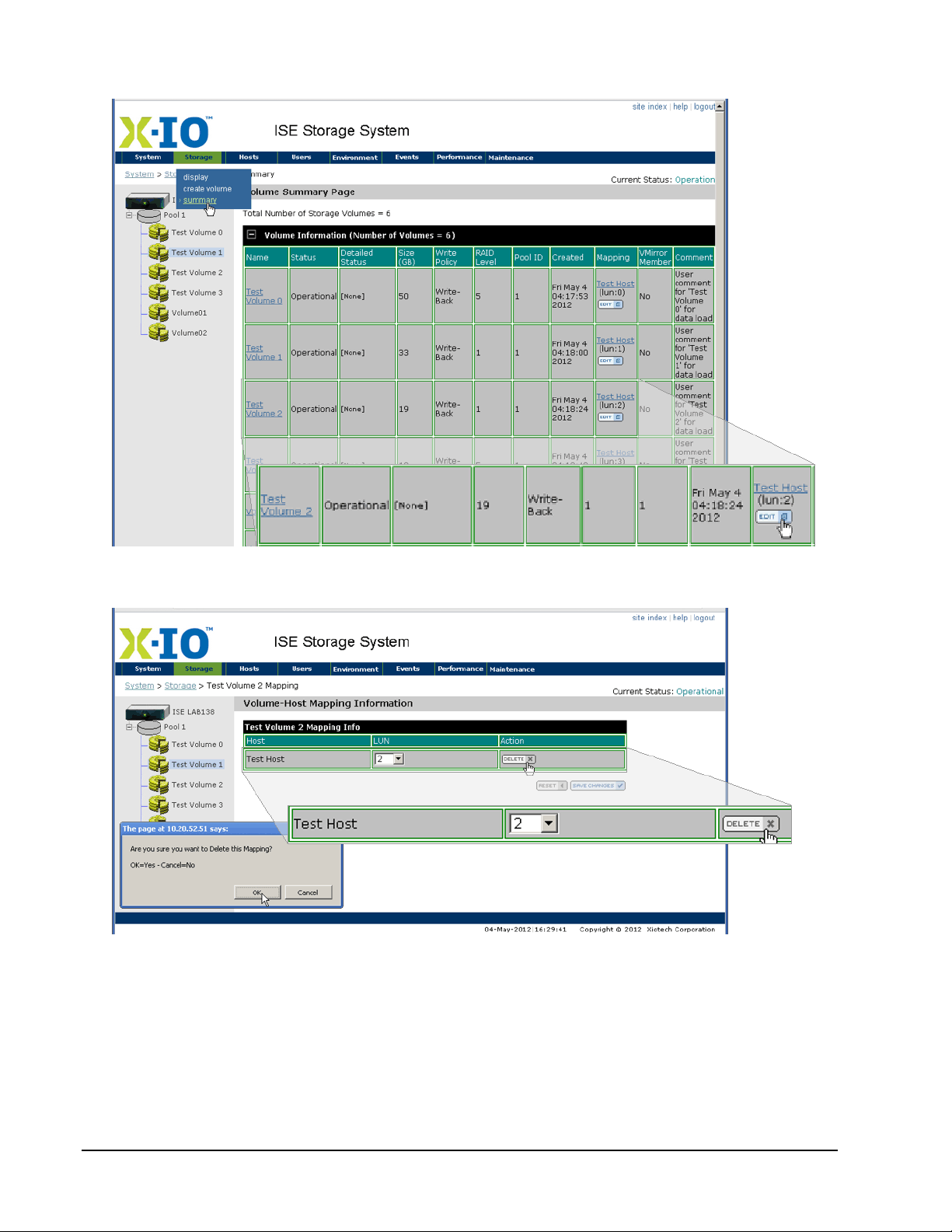
ISE User Guide ISE Management
The
Volume Summary
page (shown in Figure 57 below) appears.
Figure 57. Volume Summary–Edit
Figure 58. Volume–Host Mapping Details
Page 86 160337-000 Rev D, 30 September, 2013 Xiotech—Proprietary
Page 95
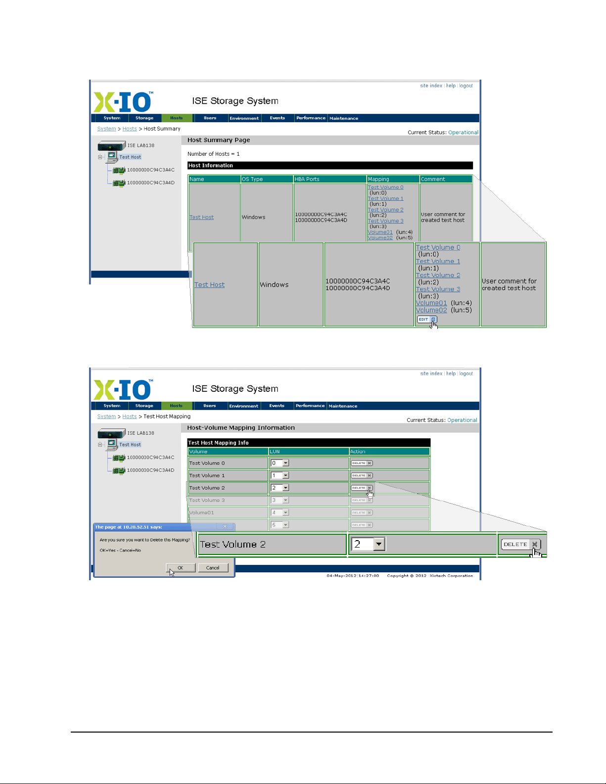
ISE Management ISE User Guide
The
Detailed Host Information
page (shown in Figure 59 below) appears. In this example, host CC1R1_P1 is
mapped to ISE1_V1 as LUN1 and to ISE1_V2 as LUN2.
Figure 59. Host Summary–Edit
Figure 60. Host–Volume Mapping Details
2. Click the drop-down in the LUN column of the mapping details page (see Figure 58 on page 86 and Figure 60 above) for the LUN assignment that is to be changed.
3. Select the desired LUN number.
4. Click
Save Changes
and the new LUN number becomes effective immediately.
CLI View, Modify LUNs
To view the LUN assignments from the CLI, enter the show host or show volume commands.
Xiotech—Proprietary 160337-000 Rev D, 30 September, 2013 Page 87
Page 96

ISE User Guide ISE Management
To change the LUN assignments using the CLI, use the present command described in “Modify Volume–
Host Mappings” on page 82, adding the :<lun> option after each host name. For example, the following
command changes the LUN through which Volume03 is mapped to host Prod02 to LUN7 from whatever LUN
was previously used:
present --volume=Volume03 Prod02:7
Mappings do not have to be removed before changing a LUN.
Re-size LUNs
The ISE supports LUN re-sizing, expansion, and contraction in place without first copying data to another
volume.
LUN re-sizing in the ISE is done in multiples of 1GB by adding to or subtracting from the currently highest
numbered logical block address. During LUN re-sizing, independent of the LUN re-size amount, host I/O to the
volume is momentarily paused (no more than ten seconds).
A re-sizing process cannot be aborted once initiated, cannot be undone, and the original presentation persists.
Presentation changes must be done manually after the LUN is re-sized. The re-size process is unaffected by
controller failovers and reboots. The ISE generates an SNMP trap (if enabled) for LUN re-size processes upon
completion and in the event of a failure (such as insufficient space or target LUN being inoperative).
LUN Expansion
When the expansion process begins, the ISE reserves enough space to complete the expansion.
LUN Contraction
The operating system volume contraction must be completed before a LUN contraction is attempted. Not all
operating systems, file systems, and databases support volume contraction. Refer to the operating system
documentation for recommended procedures prior to volume contraction.
Note. Improper use of LUN contraction results in data loss.
Orchestrator, Re-size LUNs
To re-size LUNs using the Orchestrator, select
Orchestrator User Guide.)
Web-Mgt, Re-size LUNs
Follow the steps below to re-size LUNs using the Web-Mgt.
1. Navigate to the
the
Volume Summary
2. In the
3. Click
Capacity
OK
on the confirmation message (Figure 59 on page 87) that appears and LUN expansion is com-
Detailed Volume Information
page (Figure 57) or clicking a volume icon in the left navigation panel.
field, enter a new size in GB and click
All Devices
>>
ise_name
>>
Storage View
>>
Volumes
. (See the
page (Figure 58 on page 86) by clicking the volume name on
Save Changes
.
Page 88 160337-000 Rev D, 30 September, 2013 Xiotech—Proprietary
Page 97
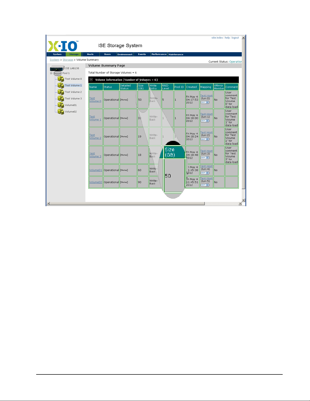
ISE Management ISE User Guide
pleted with the
Volume Summary
page showing the new size in the
Size
column.
Figure 61. Volume Summary Page–Segment
Xiotech—Proprietary 160337-000 Rev D, 30 September, 2013 Page 89
Page 98
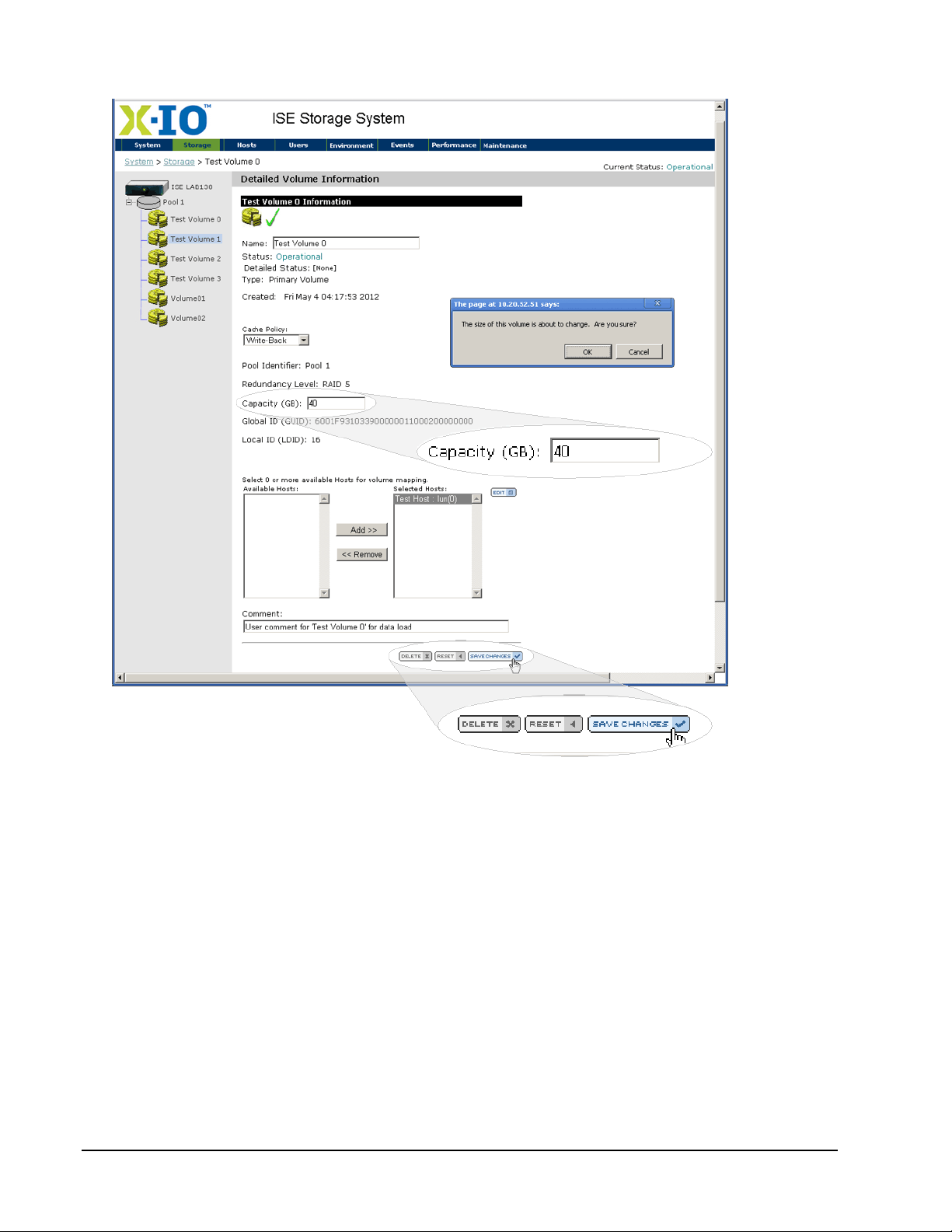
ISE User Guide ISE Management
Figure 62. LUN Re-size—Final Step
CLI, Resize LUNs
Follow the steps below to resize LUNs using the Command Line Interface.
1. At the prompt, enter modify --volume=volume1 --expand=x, where volume1 is the volume to be re-sized and x is the new size in GB. Alternatively, enter modify --volume=volume1 --size=x.
2. Press
Enter
to execute the expansion or contraction.
LUN re-sizing is completed and the volume details are shown, reflecting the new volume size.
Page 90 160337-000 Rev D, 30 September, 2013 Xiotech—Proprietary
Page 99

ISE Management ISE User Guide
Deleting Volumes
When a volume is no longer needed, its capacity can be returned to the storage pool by deleting the volume.
To do so using the Web-Mgt, follow these steps.
WARNING: Ensure that the data on the volumes is of no further use before deleting the volume.
1. Select the
•Select
•Select
•Select
Detailed Volume Information
Storage>>summary
view (see Figure 51 on page 77) by one of the following methods:
to select the Volume Summary view and then click the link to the desired
volume in the Name column or in the navigation pane.
Host>>summary
to select the Host Summary view and then click the link to the desired volume
in the Mapping column.
Storage>>display
to select the Storage Pool Information view. Expand the pool objects in the
navigation pane to display the volumes within each pool and then click the link to the desired volume.
2. Delete the volume by clicking
3. Click
OK
in the confirmation dialog that appears.
Delete
at the bottom of the view.
Note. If the volume to be deleted is mapped to any hosts, the mapping must be removed before deleting
the volume. To do so, move the host from
Selected Hosts
to
Available Hosts
and save the changes.
To delete a volume using the CLI, type delete --volume=<name>. If the volume to be deleted is mapped to
any hosts, the mapping must be removed before deleting the volume. To do so, use the unpresent command
as described in “CLI, Modify Volume–Host Mapping” on page 84. Then delete the volume.
Deleting Hosts
A host that is no longer needed can be deleted to free the HBA ports that were contained in it. These HBA
ports can then be added to existing hosts or used in new ones as needed.
Using Orchestrator
To delete hosts using the Orchestrator, select
Orchestrator User Guide.)
Using Web-Mgt
To LUNs using the Web-Mgt, follow these steps:
1. Select the Detailed Host Information view by one of the following methods:
•Select
the Name column or in the navigation pane.
•Select
host in the Mapping column.
Host>>summary
Storage>>summary
to select the Host Summary view and then click the link to the desired Host in
to select the Volume Summary view and then click the link to the desired
All Devices
>>
ise_name
>>
Host View
>>
Host
. (See the
2. Delete the host by clicking
3. Click
OK
in the confirmation dialog that appears.
Delete
at the bottom of the view.
Note. If the host to be deleted is mapped to any volumes, the mapping must be removed before deleting
the host. To do so, use the Available Volumes and Selected Volumes selection boxes on the same view to
remove the mapping and save changes. Then delete the host.
To delete a host using the CLI, type delete --host=<name>. If the host to be deleted is mapped to any
volumes, the mapping must be removed before deleting the host. To do so, use the unpresent command as
described in “CLI, View–Modify Host Configuration” on page 81. Then delete the host.
Xiotech—Proprietary 160337-000 Rev D, 30 September, 2013 Page 91
Page 100
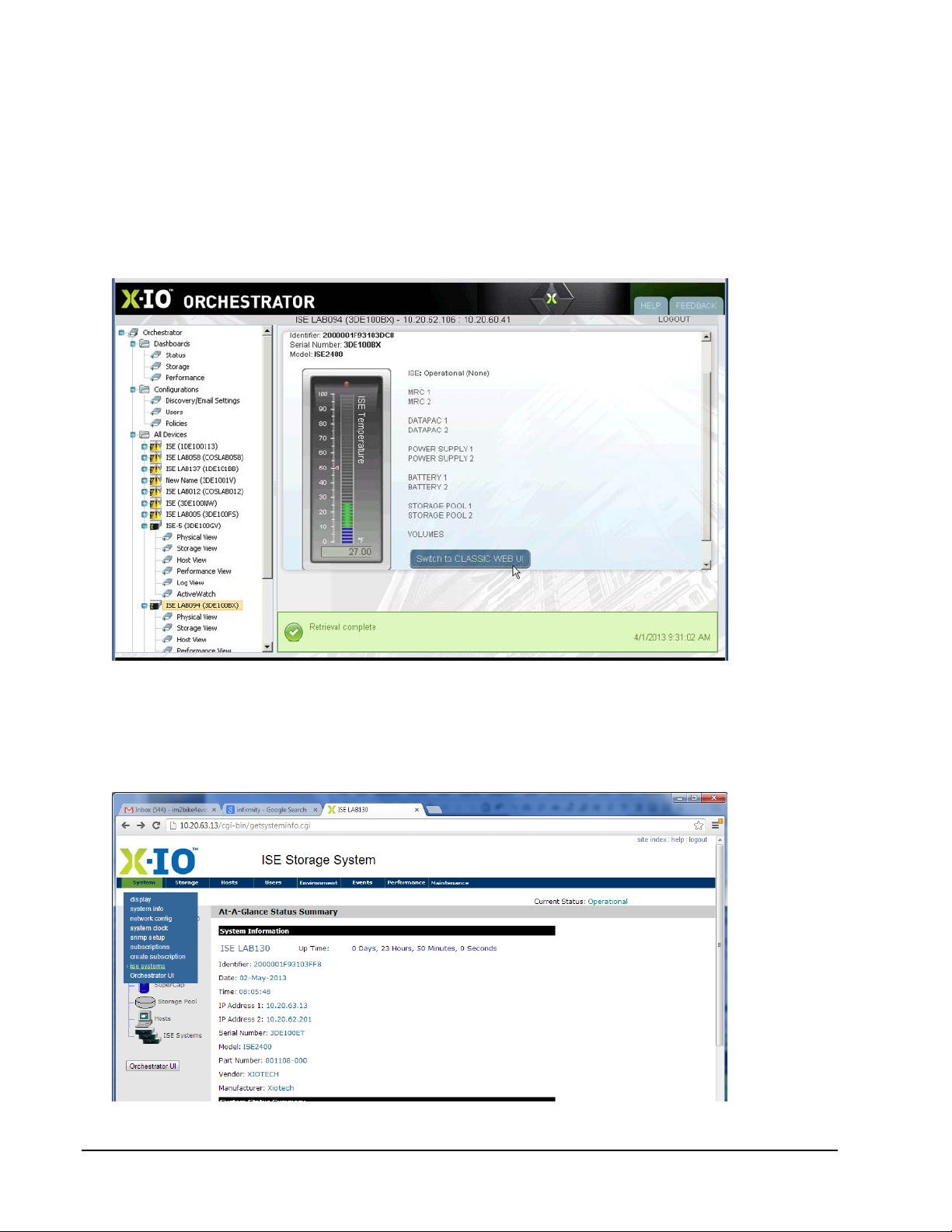
ISE User Guide ISE Management
ISE Systems Dashboard
The ISE Systems dashboard provides the means to manage and monitor multiple ISEs from within a single
ISE.
Orchestrator
Orchestrator presents an overall view of the field of all networked ISE storage that is available from any
managed ISE. From within the Orchestrator dashboard, shown below, any of these ISEs can be viewed from
the same Orchestrator session. (See the Orchestrator User Guide.)
Figure 63. ISE Systems Dashboard—Summary
Web-Mgt
This service is accessed by selecting
navigation pane (shown below).
Figure 64. Access Systems Dashboard
ise systems
from the System drop-down menu or
ISE Systems
in the left
Page 92 160337-000 Rev D, 30 September, 2013 Xiotech—Proprietary
 Loading...