

Page 1
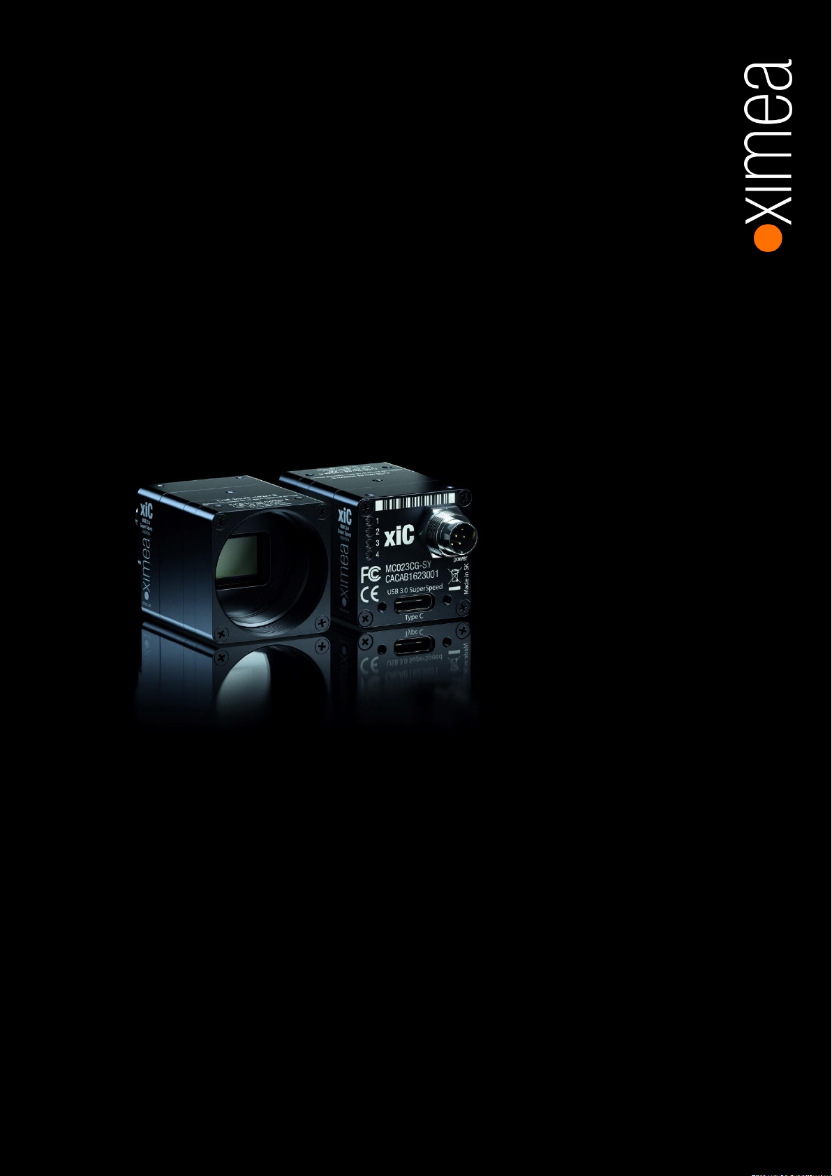
xiC
[ksi-see: or sai-see:]
• USB 3.1 camera series
Technical Manual
Version 1.16, August, 2018
Page 2

xiC - Technical Manual Version 1.16
2
Headquarters
Sales worldwide
XIMEA GmbH
Am Mittelhafen 16
48155 Münster
Germany
Tel: +49 (251) 202 408-0
Fax: +49 (251) 202 408-99
Sales America
XIMEA Corp.
8725 W 14th Ave, Ste 110
Lakewood, CO 80215
USA
Tel: +1 (303) 389-9838
Fax: +1 (303) 202-6350
R&D, Production
XIMEA s.r.o.
Lesna 52
900 33 Marianka
Slovakia
1. Introduction
1.1. About This Manual
Dear customer,
Thank you for purchasing a product from XIMEA.
We hope that this manual can answer your questions, but should you have any further questions or if you wish to claim a
service or warranty case, please contact your local dealer or refer to the XIMEA Support on our website:
www.ximea.com/support
The purpose of this document is to provide a description of the XIMEA xiC-Series cameras and to describe the correct way to
install related software and drivers and run it successfully. Please read this manual thoroughly before operating your new
camera for the first time. Please follow all instructions and observe the warnings.
This document is subject to change without notice.
1.2. About XIMEA
XIMEA is one of the worldwide leaders for innovative camera solutions with more than 20-year history of research,
development and production of digital image acquisition systems. Based in Slovakia, Germany and the US and with a global
distributor network, XIMEA offers their cameras worldwide. In close collaboration with customers XIMEA has developed a
broad spectrum of technologies and cutting-edge, highly competitive products.
XIMEA's camera centric technology portfolio comprises a broad spectrum of digital technologies, from data interfaces such as
FireWire, USB 2.0, 3.0 and USB 3.1, to cooled digital cameras with CCD and CMOS sensors, as well as smart cameras with
embedded PCs, and X-ray cameras. XIMEA has three divisions – generic machine vision and integrated vision systems,
scientific imaging and OEM/custom.
XIMEA cameras find use in many industrial applications, such as motion control, robotics, or quality control in manufacturing.
The broad spectrum of cameras also includes thermally stabilized X-ray cameras, and specialty cameras for medical
applications, research, surveillance and defense.
1.2.1. Contact XIMEA
XIMEA is a worldwide operating Company
Internet www.ximea.com
General inquiries [email protected]
Sales [email protected]
Support [email protected]
Page 3
xiC - Technical Manual Version 1.16
3
Standard Conformity
The xiC cameras have been tested using the following equipment:
Model option –UB (microB USB 3.1 conector)
• A shielded USB 3.0 cable ref. CBL-U3-3M0 (3m)
• A shielded I/O Sync cable ref. CBL-702-8P-SYNC-5M0 (5m)
Model option – TC (Type C connector in USB 3.1 Gen 1 mode)
• A shielded USB 3.1 Type-C to A cable (1m)
• A shielded I/O Sync cable ref. CBL-702-8P-SYNC-5M0 (5m)
Model option –FV and – FL
• Camera is connected to Tegra TX1 processor board via TX1CB-PHOXI-BRD and CBL-MQ-FL-0M1. Whole setup is housed
in AW16918ESS enclosure, with modified end panels to hold camera and provide access to power connector and Ethernet
connector. System is Linux operating system controlled over Ethernet from remote computer. For more information please
contact our support: https://www.ximea.com/support/wiki/allprod/Contact_Support
Warning: Changes or modifications to the product or the environment may render it ineligible for operation under CE, FCC or
other jurisdictions. XIMEA recommends using the above configuration to ensure compliance with the following standards.
Please refer also to chapter 1.2.9.
1.2.2. CE Conformity
The xiC cameras described in this manual comply with following requirements. Please refer also to chapter 1.2.9.
• EC EMC Directive 2004/108/EEC
electromagnetic compatibility of equipment
Used harmonized European standards and technical specifications:
• EN 55022:2006 + A2:2010
Information technology equipment – Radio disturbance characteristics – Limits and methods of measurement
• EN 55024:2010
Information technology equipment - Immunity characteristics - Limits and methods of measurement
• EN 61000-6-2:2005 Electromagnetic compatibility (EMC). Generic standards. Immunity for industrial environments
• EN 61000-6-3:2007 + A1:2011
Generic standards – Emission standard for residential, commercial and light-industrial environments
• EN 61000-4-2:2009 Electrostatic discharge immunity test
• EN 61000-4-3:2006 + A2:2010
Radiated, radio-frequency electromagnetic field immunity test
• EN 61000-4-4:2012 Electrical fast transient/burst immunity test
• EN 61000-4-6:2009 Immunity to conducted disturbances, induced by radio frequency fields
• EN 61000-6-1:2007 Generic standards – Immunity for residential, commercial and light-industrial environments
• EN 61326-1:2013
Electrical equipment for measurement, control and laboratory use. EMC requirements. General requirements
• EN 61000-4-8:2010
Electromagnetic compatibility (EMC). Testing and measurement techniques. Power frequency magnetic field immunity test
• EN 55016-2-3:2010
Specification for radio disturbance and immunity measuring apparatus and methods. Methods of measurement of
disturbances and immunity. Radiated disturbance measurements
Page 4
xiC - Technical Manual Version 1.16
4
1.2.3. For customers in the US: FCC Conformity
The xiC cameras described in this manual have been tested and found to comply with Part 15 of the FCC rules, which states
that:
Operation is subject to the following two conditions:
• This device may not cause harmful interference, and
• This device must accept any interference received, including interference that may cause undesired operation.
This equipment has been tested and found to comply with the limits for Class A digital device, pursuant to part 15 of the FCC
rules. These limits are designed to provide reasonable protection against harmful interference when the equipment is operated
in a commercial environment. This equipment generates, uses and can radiate radio frequency energy and, if not installed and
used in accordance with the instruction manual, may cause harmful interference to radio communications. Operation of this
equipment in a residential area is likely to cause harmful interference in which case the users will be required to correct the
interference at their own expense.
You are cautioned that any changes or modifications not expressly approved in this manual could void your authority to operate
this equipment under above jurisdictions. The shielded interface cable recommended in this manual must be used with this
equipment in order to comply with the limits for a computing device pursuant to Subpart J of Part 15 of FCC Rules.
Please refer also to chapter 1.2.9
1.2.4. For customers in Canada
The xiC cameras comply with the Class A limits for radio noise emissions set out in Radio Interference Regulations.
Please refer also to chapter 1.2.9
1.2.5. RoHS Conformity
The xiC cameras comply with the requirements of the RoHS (Restriction of Hazardous Substances) Directive
2011/65/EU.
1.2.6. WEEE Conformity
The xiC cameras comply with the requirements of the WEEE (waste electrical and electronic equipment) Directive
2003/108/EC.
1.2.7. AIA standard USB3 Vision
The xiC cameras are compliant with the USB 3.0 SuperSpeed specification and are designed to be
compliant with the AIA USB3 Vision standard.
1.2.8. GenICam GenTL API
GenICam standard transport layer interface, grabbing images. GenICam/GenTL provides an agnostic transport layer interface
to acquire images or other data and to communicate with a device. Each XIMEA camera can be GenTL Producer.
1.2.9. Camera Sub-Assemblies
The FL and FV camera models are "semi" housed with flex ribbon cable interfaces. As such, these devices do not comply with
CE/FCC/Class A limits (Canada) regulations. The system integrator (customer) is liable for compliance with CE/FCC/ Class A
limits (Canada) regulations.
Page 5

xiC - Technical Manual Version 1.16
5
1.3. Helpful Links
• XIMEA Homepage http://www.ximea.com/
• xiC USB3 Vision Camera Zone http://www.ximea.com/usb3zone
• USB3 Hardware Compatibility http://www.ximea.com/support/wiki/usb3/Compatible_hardware
• USB3.1 Updates https://www.ximea.com/support/wiki/usb3/USB_31_updates
• xiAPI stable versions download https://www.ximea.com/support/documents/4
• xiAPI beta versions download https://www.ximea.com/support/documents/14
• Frequently Asked Questions
• Knowledge Base http://www.ximea.com/support/wiki/allprod/Knowledge_Base
• Vision Libraries http://www.ximea.com/support/projects/vision-libraries/wiki
• XIMEA Registration http://www.ximea.com/en/products/register
• XIMEA Live Support http://www.ximea.com/support/wiki/allprod/XIMEA_Live_Support
• XIMEA General Terms & Conditions http://www.ximea.com/en/corporate/generaltc
http://www.ximea.com/support/wiki/allprod/Frequently_Asked_Questions
Page 6

xiC - Technical Manual Version 1.16
6
1.4. Table of Contents
1. Introduction ................................................................................................................................................................ 2
1.1. About This Manual ............................................................................................................................................. 2
1.2. About XIMEA ..................................................................................................................................................... 2
1.2.1. Contact XIMEA .......................................................................................................................................... 2
1.2.2. CE Conformity ........................................................................................................................................... 3
1.2.3. For customers in the US: FCC Conformity ................................................................................................... 4
1.2.4. For customers in Canada ........................................................................................................................... 4
1.2.5. RoHS Conformity ....................................................................................................................................... 4
1.2.6. WEEE Conformity ...................................................................................................................................... 4
1.2.7. AIA standard USB3 Vision .......................................................................................................................... 4
1.2.8. GenICam GenTL API .................................................................................................................................. 4
1.2.9. Camera Sub-Assemblies ........................................................................................................................... 4
1.3. Helpful Links ..................................................................................................................................................... 5
1.4. Table of Contents............................................................................................................................................... 6
2. xiC Camera Series .................................................................................................................................................... 11
2.1. What is xiC ...................................................................................................................................................... 11
2.2. Advantages ..................................................................................................................................................... 11
2.3. USB3 Vision Camera Applications ..................................................................................................................... 12
2.4. Common features ............................................................................................................................................ 12
2.5. Model Nomenclature ........................................................................................................................................ 13
2.6. Models Overview, sensor and models ............................................................................................................... 14
2.7. Accessories ..................................................................................................................................................... 14
3. Hardware Specification ............................................................................................................................................. 15
3.1. Power Supply .................................................................................................................................................. 15
3.2. General Specification ....................................................................................................................................... 15
3.2.1. Environment ........................................................................................................................................... 15
3.2.2. Firmware / Host driver / API features ........................................................................................................ 15
3.3. Lens Mount ..................................................................................................................................................... 16
3.3.1. Screws ................................................................................................................................................... 16
3.4. Optical path ..................................................................................................................................................... 17
3.4.1. Filter glasses .......................................................................................................................................... 17
3.4.2. Monochrome and near infrared extended camera models .......................................................................... 17
3.4.3. Color camera models .............................................................................................................................. 18
3.5. Model Specific Characteristics .......................................................................................................................... 19
3.5.1. MC023xG-SY ......................................................................................................................................... 19
3.5.1.1. Sensor and camera parameters ...................................................................................................... 19
3.5.1.2. Quantum efficiency curves [%] ........................................................................................................ 20
3.5.1.3. Dimensional drawings MC023xG-SY-TC (C-mount [with C/CS mount module B]) ............................... 20
3.5.1.4. Dimensional drawings MC023xG-SY-UB (C-mount [with C/CS mount module B]) ............................... 21
3.5.1.5. Dimensional drawings MC023xG-SY-FL (C-mount [with C/CS mount module B]) ................................ 22
3.5.1.6. Dimensional drawings MC023xG-SY-FV (C-mount [with C/CS mount module B]) ................................ 23
3.5.1.7. Referenced documents ................................................................................................................... 23
3.5.1.8. Sensor features.............................................................................................................................. 23
3.5.2. MC031xG-SY ......................................................................................................................................... 24
3.5.2.1. Sensor and camera parameters ...................................................................................................... 24
Page 7

xiC - Technical Manual Version 1.16
7
3.5.2.2. Quantum efficiency curves [%] ........................................................................................................ 25
3.5.2.3. Dimensional drawings MC031xG-SY-TC (C-mount [with C/CS mount module B]) ............................... 26
3.5.2.4. Dimensional drawings MC031xG-SY-UB (C-mount [with C/CS mount module B]) ............................... 26
3.5.2.5. Dimensional drawings MC031xG-SY-FL (C-mount [with C/CS mount module B]) ................................ 27
3.5.2.6. Dimensional drawings MC031xG-SY-FV (C-mount [with C/CS mount module B]) ................................ 28
3.5.2.7. Referenced documents ................................................................................................................... 28
3.5.2.8. Sensor features.............................................................................................................................. 28
3.5.3. MC050xG-SY ......................................................................................................................................... 29
3.5.3.1. Sensor and camera parameters ...................................................................................................... 29
3.5.3.2. Quantum efficiency curves [%] ........................................................................................................ 30
3.5.3.3. Dimensional drawings MC050xG-SY-TC (C-mount [with C/CS mount module B]) ............................... 31
3.5.3.4. Dimensional drawings MC050xG-SY-UB (C-mount [with C/CS mount module B]) ............................... 31
3.5.3.5. Dimensional drawings MC050xG-SY-FL (C-mount [with C/CS mount module B]) ................................ 32
3.5.3.6. Dimensional drawings MC050xG-SY-FV (C-mount [with C/CS mount module B]) ................................ 33
3.5.3.7. Referenced documents ................................................................................................................... 33
3.5.3.8. Sensor features.............................................................................................................................. 33
3.5.4. MC089xG-SY ......................................................................................................................................... 34
3.5.4.1. Sensor and camera parameters ...................................................................................................... 34
3.5.4.2. Quantum efficiency curves [%] ........................................................................................................ 35
3.5.4.3. Dimensional drawings MC089xG-SY-TC (C-mount [with C/CS mount module B]) ............................... 36
3.5.4.4. Dimensional drawings MC089xG-SY-UB (C-mount [with C/CS mount module B]) ............................... 36
3.5.4.5. Dimensional drawings MC089xG-SY-FL (C-mount [with C/CS mount module B]) ................................ 37
3.5.4.6. Dimensional drawings MC089xG-SY-FV (C-mount [with C/CS mount module B]) ................................ 38
3.5.4.7. Referenced documents ................................................................................................................... 38
3.5.4.8. Sensor features.............................................................................................................................. 38
3.5.5. MC124xG-SY ......................................................................................................................................... 39
3.5.5.1. Sensor and camera parameters ...................................................................................................... 39
3.5.5.2. Quantum efficiency curves [%] ........................................................................................................ 40
3.5.5.3. Dimensional drawings MC124xG-SY-TC (C-mount [with C mount module B]) ..................................... 41
3.5.5.4. Dimensional drawings MC124xG-SY-UB (C-mount [with C mount module B]) .................................... 41
3.5.5.5. Dimensional drawings MC124xG-SY-FL (C-mount [with C/CS mount module B]) ................................ 42
3.5.5.6. Dimensional drawings MC124xG-SY-FV (C-mount [with C mount module B]) ..................................... 43
3.5.5.7. Referenced documents ................................................................................................................... 43
3.5.5.8. Sensor features.............................................................................................................................. 43
3.6. User interface – LEDs ...................................................................................................................................... 44
3.7. xiC USB 3.1 Gen1 Type-C Interface .................................................................................................................. 45
3.7.1. Type-C connector location ....................................................................................................................... 45
3.7.2. Pinning ................................................................................................................................................... 45
3.8. xiC USB 3.1 Gen1 micro B Interface .................................................................................................................. 46
3.8.1. USB 3.1 micro B Location ........................................................................................................................ 46
3.8.2. Pinning ................................................................................................................................................... 46
3.9. xiC Flex cable interface .................................................................................................................................... 47
3.9.1. Flex Connection Location ......................................................................................................................... 47
3.9.2. Pinning ................................................................................................................................................... 47
3.9.3. Inserting / detaching FPC cable................................................................................................................ 48
3.10. xiC Digital Input / Output (GPIO) Interface .......................................................................................................... 51
Page 8

xiC - Technical Manual Version 1.16
8
3.10.1. Location ................................................................................................................................................. 51
3.10.2. IO Connector Pinning .............................................................................................................................. 51
3.10.3. Optically isolated Digital Input .................................................................................................................. 52
3.10.3.1. Optically isolated Digital Input - General info .................................................................................... 52
3.10.3.2. Digital Input – signal levels ............................................................................................................. 52
3.10.3.3. Digital Input – Internal Schematic .................................................................................................... 53
3.10.3.4. Digital Input – Wiring ...................................................................................................................... 53
3.10.3.5. Digital Input – Timing ..................................................................................................................... 54
3.10.4. Optically isolated Digital Output ................................................................................................................ 54
3.10.4.1. Optically isolated Digital Output - General info .................................................................................. 54
3.10.4.2. Optically isolated Digital Output Delay .............................................................................................. 54
3.10.4.3. Optically isolated Digital Output – Internal schematic ........................................................................ 55
3.10.4.4. Digital Output – Wiring ................................................................................................................... 55
3.10.4.5. Digital Output – Timing ................................................................................................................... 60
3.10.5. Non-isolated Digital Lines (-UB and -TC only) ............................................................................................ 61
3.10.5.1. Non-isolated Digital Input/Output (INOUT) General info ...................................................................... 61
3.11. External power supply input (AUX) ..................................................................................................................... 61
3.12. Heat Dissipation ............................................................................................................................................... 62
3.13. CBL-U3-1M0 / CBL-U3-3M0 / CBL-U3-5M0 ..................................................................................................... 63
3.14. CBL-U3-3M0-ANG ........................................................................................................................................... 64
3.15. CBL-MQ-FL-0M1 ............................................................................................................................................. 65
3.16. BOB-MQ-FL .................................................................................................................................................... 65
3.17. CBL-702-8P-SYNC-5M0 .................................................................................................................................. 66
3.18. Tripod Adapter – MECH-MC-BRACKET-KIT ........................................................................................................ 67
3.18.1. Dimensional drawings ............................................................................................................................. 67
3.19. USB 3 host adapters ........................................................................................................................................ 68
4. Operation ................................................................................................................................................................. 69
4.1. System Requirements ...................................................................................................................................... 69
4.1.1. Software Requirements ........................................................................................................................... 69
4.1.2. Hardware Requirements .......................................................................................................................... 69
4.1.2.1. System Configuration ..................................................................................................................... 69
4.1.2.2. USB 3.1 Host Adapter .................................................................................................................... 70
4.1.2.3. Cables ........................................................................................................................................... 70
4.2. Video Formats ................................................................................................................................................. 71
4.2.1. Full Resolution ........................................................................................................................................ 71
4.2.2. ROIs – Region Of Interest ........................................................................................................................ 71
4.2.3. Downsampling Modes ............................................................................................................................. 71
4.2.3.1. Binning .......................................................................................................................................... 71
4.2.3.2. Skipping ........................................................................................................................................ 71
4.2.4. Image Data Output Formats ..................................................................................................................... 72
4.2.5. Digitization bit depth................................................................................................................................ 73
4.3. Acquisition modes ........................................................................................................................................... 74
4.3.1. Free-Run ................................................................................................................................................ 74
4.3.2. Trigger controlled Acquisition/Exposure .................................................................................................... 74
4.3.2.1. Triggered acquisition - single frame ................................................................................................ 75
4.3.2.2. Triggered acquisition - burst of frames ............................................................................................ 76
Page 9

xiC - Technical Manual Version 1.16
9
4.3.2.3. Exposure defined by trigger pulse length ......................................................................................... 76
4.3.2.4. Multiple exposures in one frame ..................................................................................................... 77
4.4. Camera Parameters and Features ..................................................................................................................... 78
4.4.1. Exposure Time ........................................................................................................................................ 78
4.4.2. Gain ....................................................................................................................................................... 78
4.5. Host-Assisted Image Processing Parameters Available in xiAPI. .......................................................................... 78
4.5.1. Auto Exposure – Auto Gain ...................................................................................................................... 78
4.5.2. White Balance ........................................................................................................................................ 78
4.5.2.1. Assisted Manual White Balance ...................................................................................................... 78
4.5.2.2. Auto White Balance ........................................................................................................................ 78
4.5.3. Gamma .................................................................................................................................................. 78
4.5.4. Sharpness .............................................................................................................................................. 78
4.5.5. Color Correction Matrix ............................................................................................................................ 79
4.5.6. Sensor Defect Correction ......................................................................................................................... 79
5. Software .................................................................................................................................................................. 80
5.1. Accessing the Camera ..................................................................................................................................... 80
5.1.1. Proprietary API ........................................................................................................................................ 80
5.1.2. Standard Interface .................................................................................................................................. 80
5.1.2.1. GenICam ....................................................................................................................................... 80
5.1.2.2. USB3 Vision ................................................................................................................................... 80
5.1.3. Vision Library Integration ......................................................................................................................... 80
5.2. XIMEA CamTool ............................................................................................................................................... 81
5.3. Supported Vision Libraries ................................................................................................................................ 83
5.3.1. Libraries maintained by XIMEA ................................................................................................................. 83
5.3.1.1. MathWorks MATLAB ...................................................................................................................... 83
5.3.1.2. MVTec HALCON ............................................................................................................................. 83
5.3.1.3. National Instruments LabVIEW Vision Library .................................................................................... 83
5.3.1.4. OpenCV ......................................................................................................................................... 83
5.4. XIMEA Windows Software Package ................................................................................................................... 84
5.4.1. Contents ................................................................................................................................................ 84
5.4.2. Installation .............................................................................................................................................. 84
5.5. XIMEA Linux Software Package ......................................................................................................................... 87
5.5.1. Contents ................................................................................................................................................ 87
5.5.2. Installation .............................................................................................................................................. 87
5.6. XIMEA macOS Software Package ...................................................................................................................... 89
5.6.1. Contents ................................................................................................................................................ 89
5.6.2. Installation .............................................................................................................................................. 89
5.6.3. Start XIMEA CamTool .............................................................................................................................. 90
5.7. Programming .................................................................................................................................................. 91
5.7.1. XIMEA APIs ............................................................................................................................................. 91
5.7.2. xiAPI Overview ........................................................................................................................................ 91
5.7.3. xiAPI Functions Description ...................................................................................................................... 91
5.7.4. xiAPI Parameters Description ................................................................................................................... 92
5.7.5. xiAPI Examples ....................................................................................................................................... 92
5.7.5.1. Connect Device .............................................................................................................................. 92
5.7.5.2. Parameterize Device ....................................................................................................................... 92
Page 10

xiC - Technical Manual Version 1.16
10
5.7.5.3. Acquire Images .............................................................................................................................. 93
5.7.5.4. Control Digital Input / Output (GPIO) ................................................................................................ 93
5.7.6. xiAPI Auto Bandwidth Calculation ............................................................................................................. 94
5.7.7. USB3 Vision ............................................................................................................................................ 94
5.7.8. GenICam ................................................................................................................................................ 94
5.8. XIMEA Control Panel ........................................................................................................................................ 95
6. Appendix .................................................................................................................................................................. 96
6.1. Troubleshooting and Support ............................................................................................................................ 96
6.1.1. Worldwide Support .................................................................................................................................. 96
6.1.2. Before Contacting Technical Support ........................................................................................................ 96
6.1.3. Frequently Asked Questions ..................................................................................................................... 96
6.1.3.1. What is USB 3.1 Gen 1 SuperSpeed? .............................................................................................. 96
6.1.3.2. What is the real transfer speed? ...................................................................................................... 97
6.1.3.3. Why can I not achieve maximum transfer speed? ............................................................................. 97
6.1.3.4. What voltage should be applied to Digital Input of xiC to turn it on/off? .............................................. 97
6.1.3.5. What is the implementation of Digital Output (VDO) of xiC? ............................................................... 97
6.2. Product service request (PSR) ........................................................................................................................... 98
6.2.1. Step 1 - Contact Support ......................................................................................................................... 98
6.2.2. Step 2 - Create Product Service Request (PSR) ......................................................................................... 98
6.2.3. Step 3 - Wait for PSR Approval ................................................................................................................ 98
6.2.4. Step 4 - Sending the camera to XIMEA ..................................................................................................... 98
6.2.5. Step 5 - Waiting for Service Conclusion .................................................................................................... 98
6.2.6. Step 6 - Waiting for return delivery ........................................................................................................... 98
6.3. Safety instructions and precautions ................................................................................................................... 99
6.3.1. Disassembling ........................................................................................................................................ 99
6.3.2. Mounting / Screwing ............................................................................................................................... 99
6.3.3. Connections ........................................................................................................................................... 99
6.3.4. Power supply .......................................................................................................................................... 99
6.3.5. Environment / protect against water ......................................................................................................... 99
6.3.6. Recommended light conditions. ............................................................................................................... 99
6.3.7. Protect the optical components .............................................................................................................. 100
6.3.8. Mechanical loads .................................................................................................................................. 100
6.3.9. Camera / lens cleaning.......................................................................................................................... 100
6.3.10. Protect against static discharge (ESD) .................................................................................................... 100
6.4. Warranty ....................................................................................................................................................... 100
6.5. Disclaimer of Warranty ................................................................................................................................... 101
6.6. List Of Trademarks ........................................................................................................................................ 101
6.7. Standard Terms & Conditions of XIMEA GmbH ................................................................................................. 101
6.8. Copyright ...................................................................................................................................................... 106
6.9. Revision History ............................................................................................................................................. 106
7. Glossary ................................................................................................................................................................. 107
8. list of figures .......................................................................................................................................................... 108
9. list of tables ........................................................................................................................................................... 111
Page 11
xiC - Technical Manual Version 1.16
11
Industry standard interface
USB 3.1 Gen1
AIA standard compatibility
USB3 Vision standard
Small
Fits into places where no other camera can fit
Low power consumption
2.2-3.5 W
Powerful
5Gb/s interface up to 450Mbyte/s data throughput for USB3.1 gen1
Fast
High speed, high frame rate: >650fps at VGA and 30fps at 12Mpix resolutions
Robust
Full metal housing, no sheet metal covers
Lightweight
Facilitates increased performance of robotic arms and gimbals
Connectivity
Programmable opto-isolated I/O, and non-isolated digital input and output. 4 status LEDs
Compatibility
Support for Windows, Linux and MacOS, ARM, various Image Processing Libraries
Software interfaces
GenICam / GenTL and highly optimized xiAPI SDK
Economical
Excellent value and price, low TCO and fast ROI
2. xiC Camera Series
2.1. What is xiC
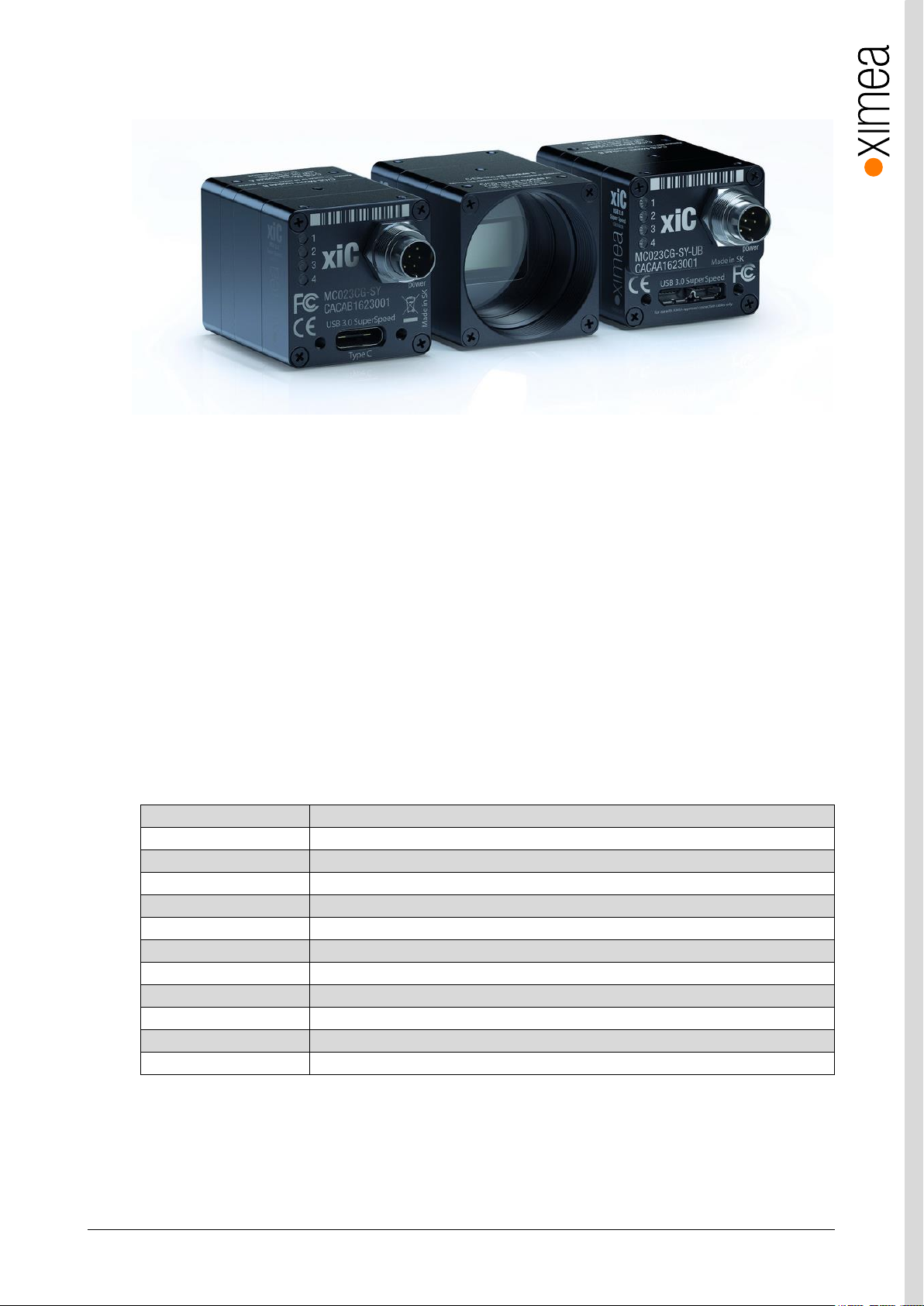
xiC [
ksi-see: or sai-see:]
• Extremely small footprint, very light
• Low power consumption
• USB3 Vision Standard compatible
• sensors: 2.3 MP, 3.1 MP, 5.0 MP, 8.9 MP and 12.4 MP, b/w, color Sony sensors
• frame rates: 2.3 MP @ 165 fps to 12.4 MP @ 31 fps
The XiC camera line comes with several options for interface to the host computer; standard USB (type-C and micro-B) and
custom flex line connections. At the time of writing, the USB cameras utilize USB 3.1 gen1 definitions and yield a bandwidth of
about 450 Mbyte/s. The cameras are backward compatible with USB 3.0 and 2.0 (with concomitant reduction in pixel
throughput).
2.2. Advantages
is an ultra-compact USB 3.1 (gen 1) Industrial camera family with outstanding features:
table 2-1, advantages
Page 12
xiC - Technical Manual Version 1.16
12
Sensor Technology
CMOS, Global shutter
Acquisition Modes
Continuous, software and hardware trigger, fps limiting, triggered exposure and burst
Partial Image Readout
ROI, Skipping and Binning modes supported (model specific)
Image data formats
8, 10 or 12 bit RAW pixel data
Color image processing
Host based de-bayering, sharpening, Gamma, color matrix, true color CMS
Hot/blemish pixels correction
On camera storage of up to 5000 pixel coordinates, host assisted correction
Auto adjustments
Auto white balance, auto gain, auto exposure
Flat field corrections
Host assisted pixel level shading and lens corrections
Image Data and Control
Interface
USB 3.1 standard Micro B and standard Type-C with screw lock threads and flat ribbon
for embedded implementation compliant to USB3 Vision standard
General Purpose I/O
1x opto-isolated input, 1x opto-isolated output, and 2 non-isolated bidirectional I/O, 4X
user configurable LEDs
Signal conditioning
Programmable debouncing time (planned)
Synchronization
Hardware trigger input, software trigger, exposure strobe output, busy output
Housing and lens mount
Standard C-mount convertible to CS mount, and “semi-housed”
Power requirements
2.2-3.5W, supplied via USB 3.1 interface
Environment
Operating 0°C to 50°C on housing, RH 80% non-condensing, -30°C to 60°C storage
Ingress Protection: IP40
Operating systems
Windows 10 (x86 and x64), Windows 7 (x86 and x64), Linux Ubuntu, MacOS 10.8 and
newer
Software support
xiAPI SDK, adapters and drivers for various image processing packages
Firmware updates
Field firmware updatable
2.3. USB3 Vision Camera Applications
• Automation
• Ultra-fast 3D scanning
• Miniature and fast robotic arms
• Mobile devices
• In-situ optical inspection camera
• Material and life science microscopy
• Ophthalmology and retinal imaging
• Broadcasting
• Fast process capture, e.g. golf club swings
• Intelligent Transportations Systems (ITS) and traffic monitoring
2.4. Common features
table 2-2, common features
Page 13

xiC - Technical Manual Version 1.16
13
2.5. Model Nomenclature
Part number convention for the different models:
MCxxxyG-zz[-OPT]n
MC xiC family name
xxx: Resolution in 0.1 MPixel. E.g. 2.3 MPixel Resolution: xxx = 023
y: y=C: color model
y=M: black & white model
G: Global shutter (all XiC cameras are global shutter)
zz: Vendor of the sensor
zz = SY: Sony
[-OPT]: Options
OPT = TC: connector Type-C
OPT = UB: connector micro B
OPT = FL: flexline variant, connector parallel to board, semi-housed
OPT = FV: flexline variant, connector perpendicular to board, semi-housed
Page 14
xiC - Technical Manual Version 1.16
14
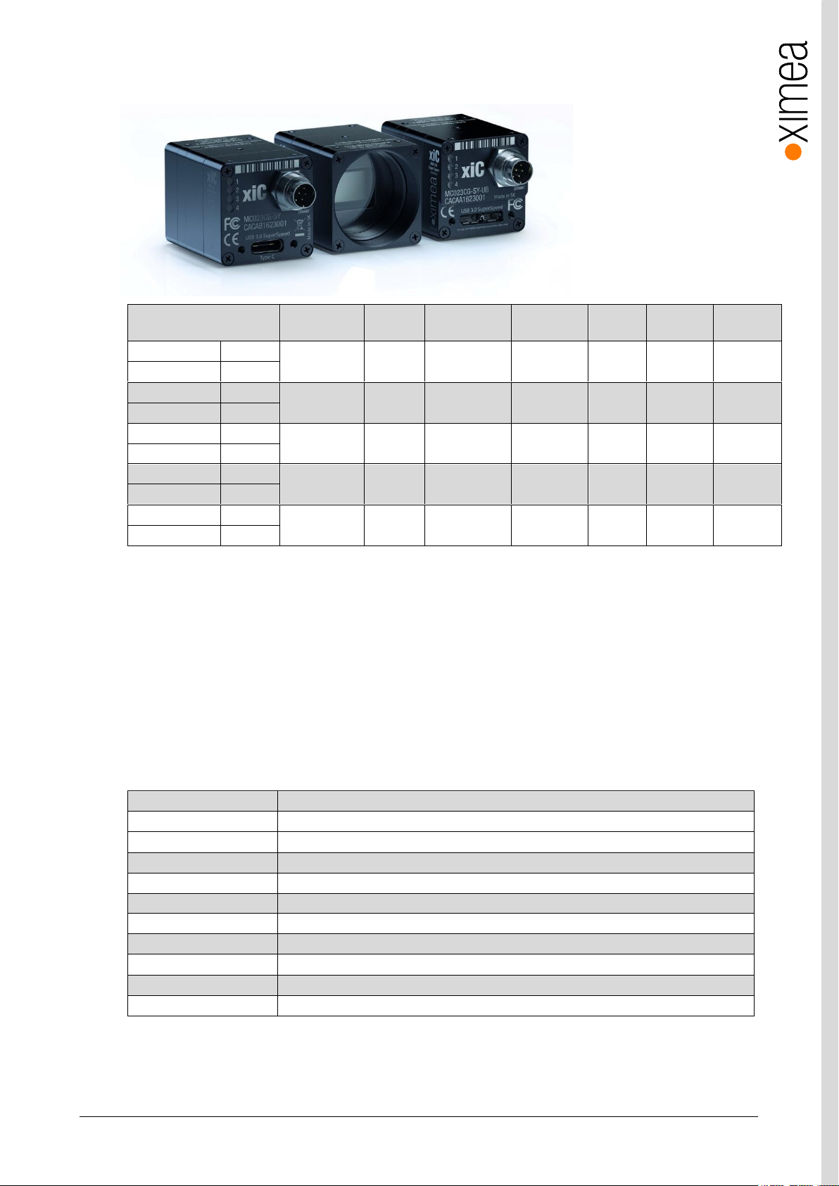
Model1 Resolution
Pixel
size
ADC [bit]
DR
Optical
size
Sensor
diagonal
FPS
2
MC023MG-SY
b/w
1936 x 1216
5.86 µm
10/12
71.7 dB
1/1.2”
13.4 mm
165
MC023CG-SY
Color
MC031MG-SY
b/w
2064 x 1544
3.45 µm
8/10/12
70.8 dB
1/1.8”
8.9 mm
122
MC031CG-SY
Color
MC050MG-SY
b/w
2464 x 2056
3.45 µm
8/10/12
70.8 dB
2/3”
11.1 mm
76
MC050CG-SY
Color
MC089MG-SY
b/w
4112 x 2176
3.45 µm
8/10/12
70.5 dB
1”
16.1 mm
43
MC089CG-SY
Color
MC124MG-SY
b/w
4112 x 3008
3.45 µm
8/10/12
70.5 dB
1.1”
17.6 mm
31
MC124CG-SY
Color
Item P/N
Description
CBL-U3-1M0
1.0m USB 3.0 cable, micro B connector on camera side
CBL-U3-3M0
3.0m USB 3.0 cable, micro B connector on camera side
CBL-U3-3M0-ANG
3.0m USB 3.0 cable, angled micro B USB3 connector
CBL-U3-5M0
5.0m USB 3.0 cable, micro B connector on camera side
MECH-MC-BRACKET-KIT
xiC series tripod mounting bracket with Screws Kit
CBL-MQ-FL-0M1
Cable FPC MQ/MC Flex-Line, 0.1m
BOB-MQ-FL
Break Out Board, Flex-Line, Simple Board Level Micro-B USB3.0
U31PE1G3-V1-X21
PCI express adapter, 2x USB 3.1 ports asmedia ASM1142, xHCI
U3PE-FL1100-X41
PCI express adapter, 4x USB 3.0 ports, PCIe x4 slot
CBL-702-8P-SYNC-5M0
5.0m Trigger/Sync I/O cable
2.6. Models Overview, sensor and models
table 2-3, models overview
Note: 1) In the model name please add
2) Full resolution, 8-bit RAW
2.7. Accessories
The following accessories are available (short list):
-TC for USB 3.1 Gen1 Type C
-UB for USB 3.1 Gen1 Micro B
-FL for flat-flex cable connecting from the bottom of the camera
-FV for flat-flex cable connecting perpendicular to the sensor
table 2-4, accessories
Note: 1) For more information please visit:
https://www.ximea.com/support/projects/usb3/wiki/USB_3_Host_Adapters
Page 15
xiC - Technical Manual Version 1.16
15
3. Hardware Specification
3.1. Power Supply
The xiC cameras are powered via the USB Micro-B, type C or flexline connector. The input voltage is 5 V DC. The power
consumption is 2.2 -3.5W depending on the xiC model.
Power supply, via USB system connector:
• 5 V (nominal)
• 4.45 V to 5.5 V (at the camera connector)
Additionally, the models with Micro-B (-UB) and type-C (-TC) connector can use external power supply, with same requirements
as power supply defined above. For information about connection please see chapter: 3.9.3 Inserting / detaching FPC cable
• When inserting or detaching cables increased caution need to be taken, to prevent connector or cable damage. MC
cameras interface connectors are equipped with locking mechanism. When locked pulling the cable may lead to damage of
connector or camera. When manipulating with cable the power supply for the camera must be turned off.
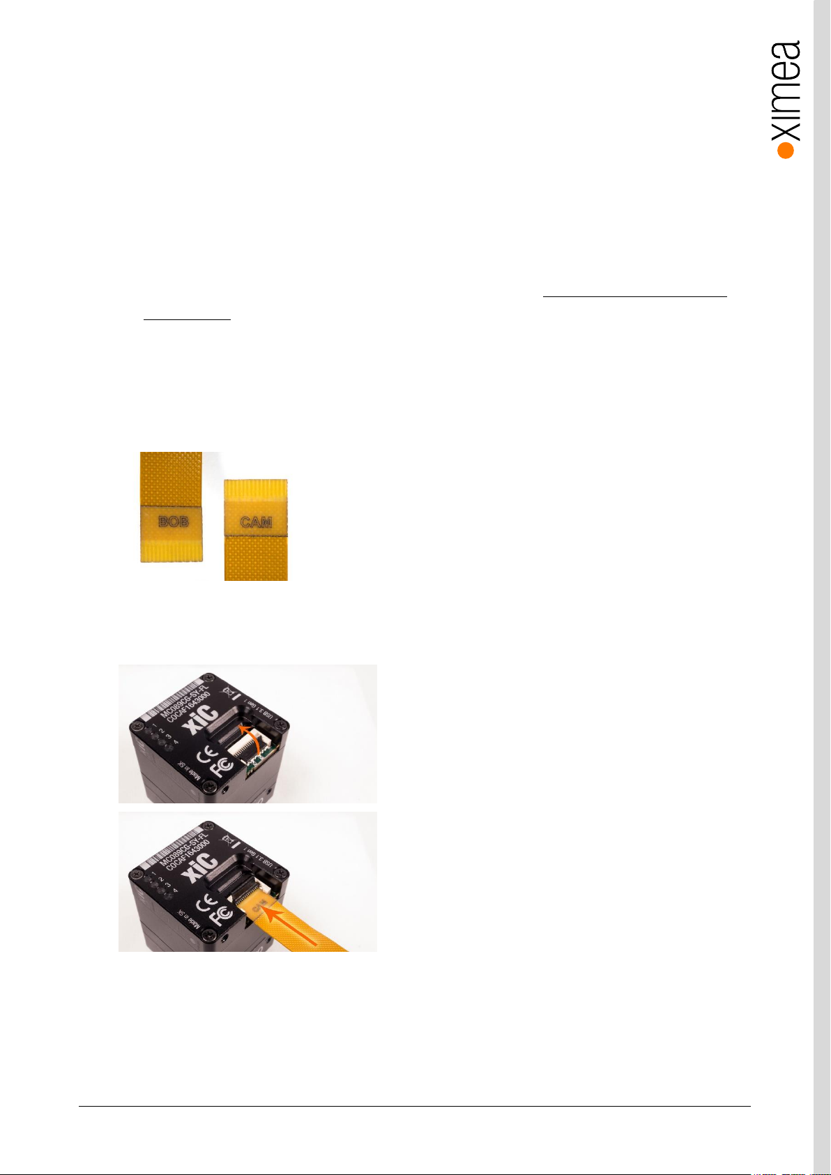
Cable have marked ends. It is important to connect the end marked “CAM” to the camera and end marked “BOB” to host or
adapter. Swapped orientation can cause damage to camera. It is important that the power is turned off when
inserting/detaching the cable.
figure 3-38, MC FPC cable laser marking
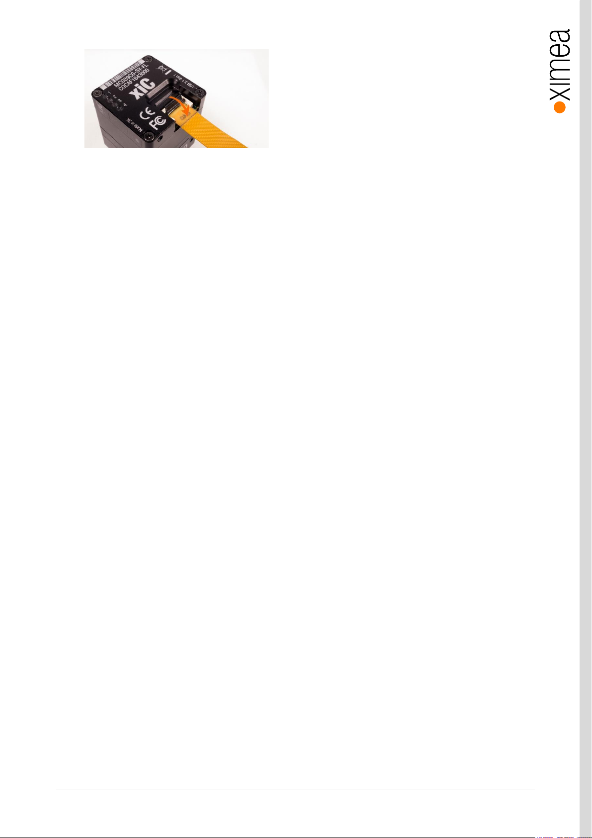
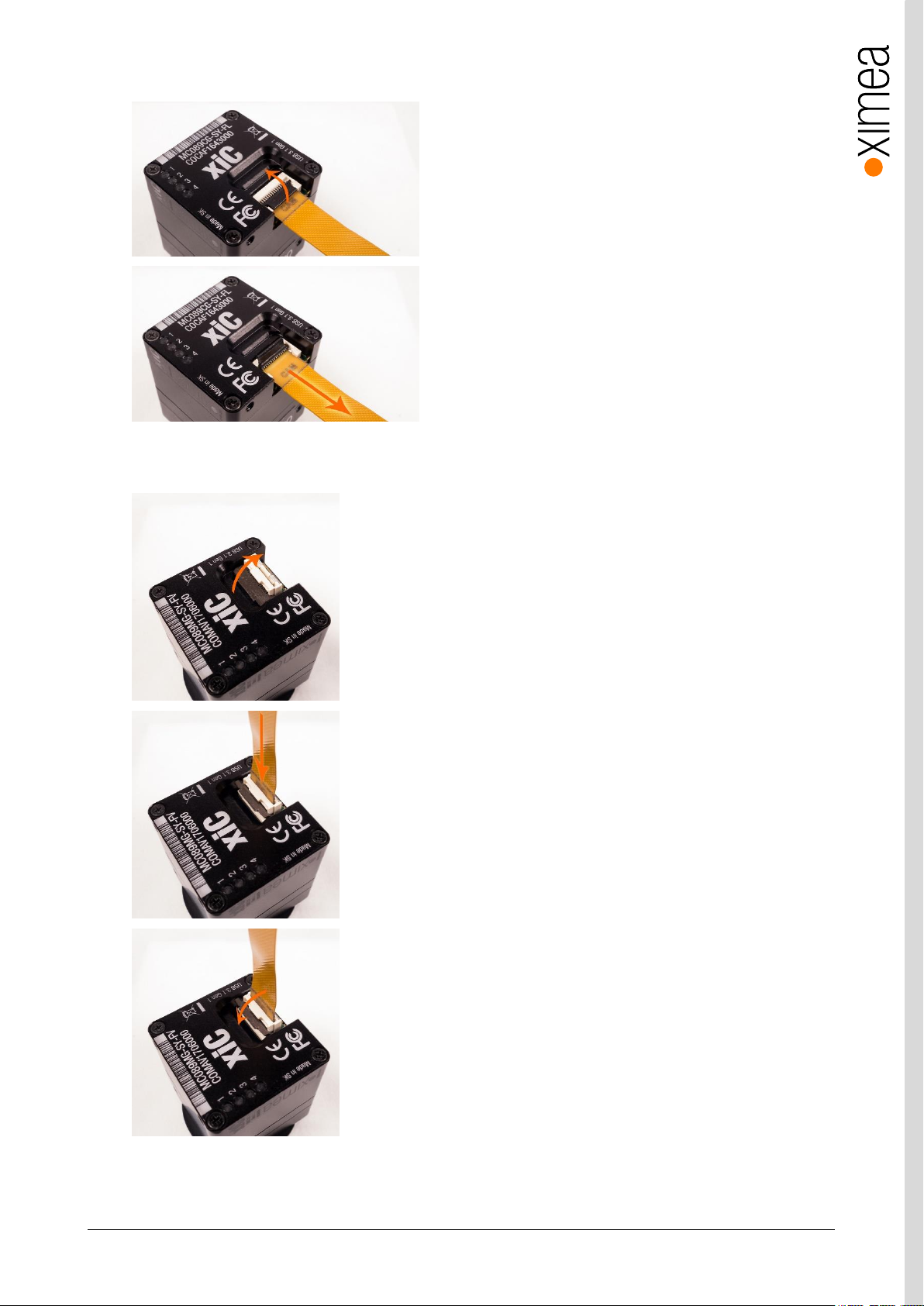
Inserting FPC cable MC option -FL
Open connector lock
Insert cable
Page 16
xiC - Technical Manual Version 1.16
16
figure 3-39, MC FPC insert procedure option -FL
Close connector lock
Page 17
xiC - Technical Manual Version 1.16
17
Detaching FPC cable MX X2G2 option –FL
figure 3-40, MC FPC detach procedure option -FL
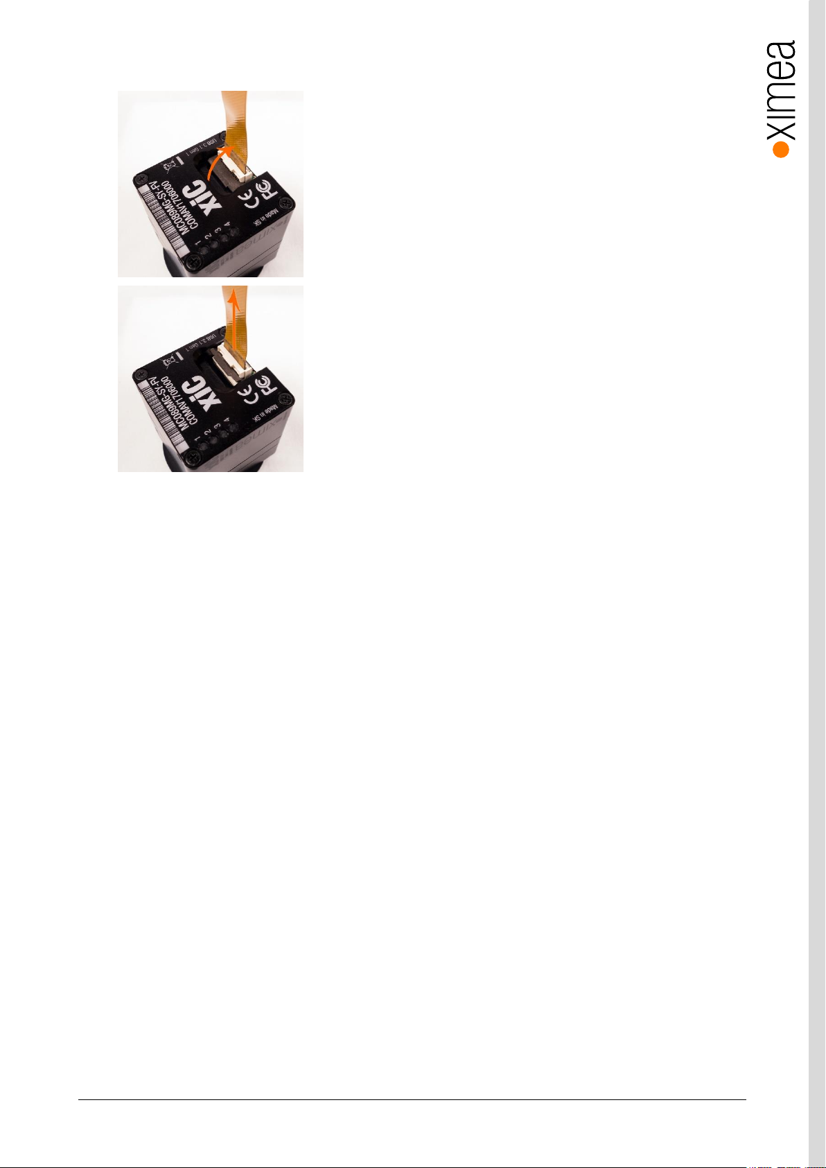
Inserting FPC cables MC option -FV
Open connector lock
Pull cable gently in marked direction.
Open connector lock
Insert cable
Close connector lock.
figure 3-41 MC FPC insert procedure option -FV
Page 18
xiC - Technical Manual Version 1.16
18
Detaching FPC cable MX X2G2 option –FV
Open connector lock
Pull gently the cable out as marked.
figure 3-42, MC FPC detach procedure option -FV
Page 19
xiC - Technical Manual Version 1.16
19
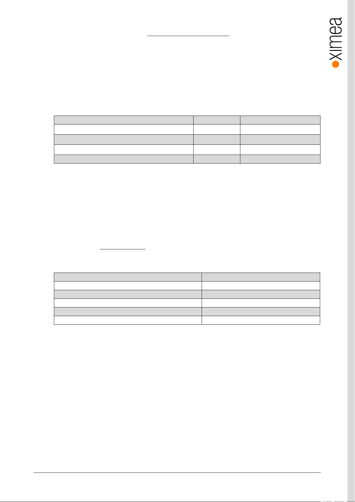
Description
Symbol
Value
Optimal ambient temperature operation
T
opt
+10 to +25 °C
Ambient temperature operation
T
max
+0 to +50 °C
Ambient temperature for storage and transportation
T
storage
-30 to +60 °C
Relative Humidity, non-condensing
RH
80 %
Description
Value
Interpolation methods
Proprietary
White balance coefficients ranges
0.0 to 3.9
Sharpness filter
-400 to 400 %
Gamma
0.3 to 1.0
Full color correction matrix (3+1)x3 coefficients ranges
-3.9 to 3.9
xiC Digital Input / Output (GPIO) Interface and 3.11 External power supply input (AUX).
Power supply, via Digital Input / Output (GPIO) Interface connector:
• 5 V (nominal)
• 4.45 V to 5.5 V (at the camera connector)
3.2. General Specification
3.2.1. Environment
table 3-1, environment
Housing temperature must not exceed +65°C. It is recommended to mount the camera on heat conductive structure to
improve heat dissipation. The following parameters are not guaranteed if the camera is operated outside the optimum range:
• Dark current
• Dynamic Range
• Linearity
• Acquisition and readout noise
• S/N ratio, durability
Please refer to chapter 3.12 Heat Dissipation.
3.2.2. Firmware / Host driver / API features
table 3-2, firmware / API features
More details on API/SDK features are available at XIMEA support pages: https://www.ximea.com/support/wiki/apis/APIs
Page 20
xiC - Technical Manual Version 1.16
20
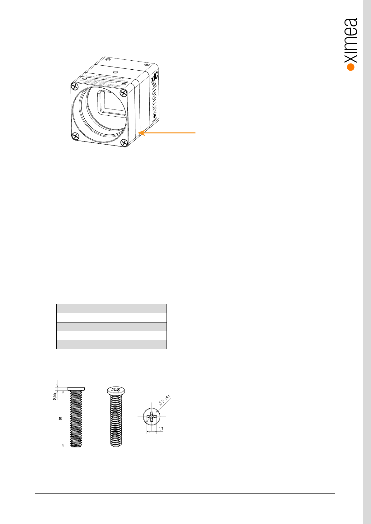
Material
Steel
Surface
Black zinc
Thread
M2
Driver
PH 00
Avail. Lengths
3mm – 24 mm
C/CS-Mount module B
3.3. Lens Mount
The xiC cameras are compatible with C-mount and CS-mount lenses.
figure 3-1, position C/CS-Mount module B
The cameras are delivered with C-mount back focal length. By removing the “C/CS-Mount module B” (see the figure above)
the camera can be rebuilt to CS-mount compatibility. Effectively reducing the back focal distance and overall length of camera
by 5mm. The required M2x8mm special screws are part of the camera delivery. The length of the lens thread is 6.5 mm.
Please read the chapter 3.4 Optical path carefully. Conversion between those two options is described:
https://www.ximea.com/support/projects/usb3/wiki/Convert_C_to_CS_Mount
Note: The distance between the threaded flange and the surface of the filter glass is 11.9 mm in case of C-Mount and 6.9
mm in case of CS-Mount. To avoid damaging of the filter glass, nothing may extend deeper into the housing.
Lens mount adapter configuration:
• C-Mount (with C/CS Mount module B)
• CS-Mount (without C/CS Mount module B)
3.3.1. Screws
All mounting screws are customized M2 screws with different lengths.
Technical details:
table 3-3, custom screws, technical details
Drawings, e.g. with 10mm length:
figure 3-2, xiC mounting screws
Note: Never exceed a maximum torque of 0.3Nm when fastening the M2 mounting screws.
Page 21
xiC - Technical Manual Version 1.16
21
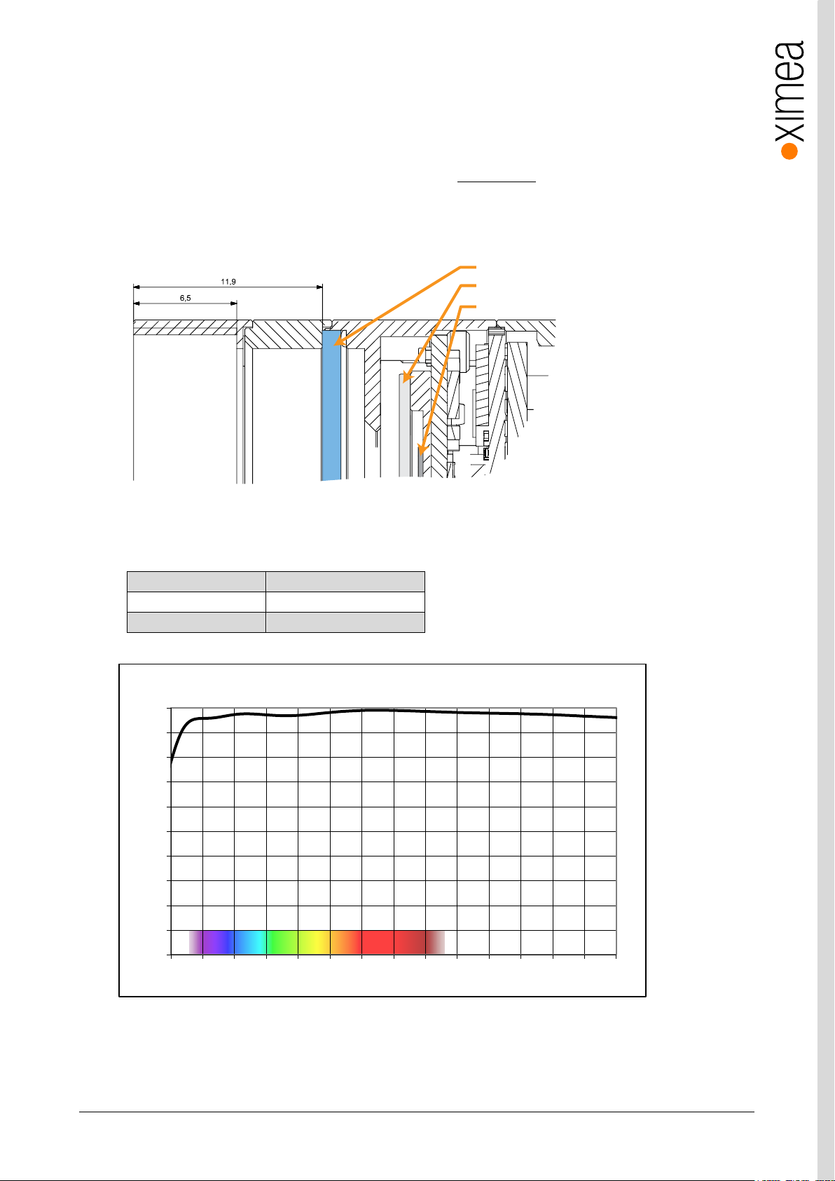
Used filter brand
BK7 AR2x
Thickness
1.0±0.1 mm
Coating
Anti-reflex both sides
filter glass
sensor cover glass
sensor die
0
10
20
30
40
50
60
70
80
90
100
350 400 450 500 550 600 650 700 750 800 850 900 950 1000 1050
Transmittance (%)
Wavelength (nm)
BK7 AR2x - Transmission Curve
3.4. Optical path
3.4.1. Filter glasses
A filter glass is part of the optical path of the camera. This glass is placed on a layer of silicone, to keep dust out of the camera,
but not glued. The conversion of C-mount to CS-mount (see section 3.3 Lens Mount) must be carried out carefully. Operating
the camera without a lens mount is not intended and can lead to dropping out of the filter glass and the entry of dust. Do not
use compressed air to clean the camera as this could push dust into the camera. Distance from the flange to sensor is designed
so the optical distance is 17.526mm - 0.2mm.
figure 3-3, Optical path section
3.4.2. Monochrome and near infrared extended camera models
table 3-4, monochrome camera - filter glass parameter
figure 3-4, monochrome camera - filter glass transmission curve
Page 22
xiC - Technical Manual Version 1.16
22
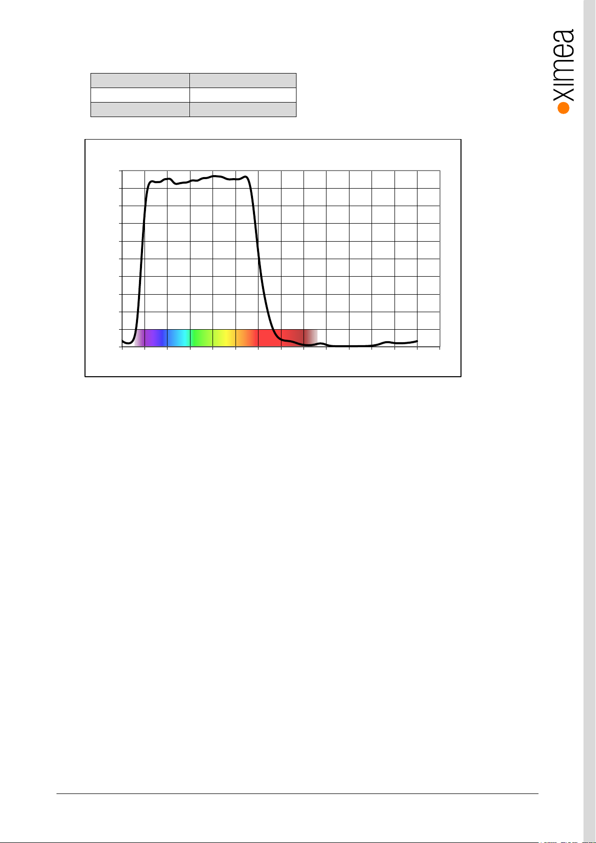
Used filter brand
ICR650
Thickness
1.0±0.1 mm
Coating
NA
0
10
20
30
40
50
60
70
80
90
100
350 400 450 500 550 600 650 700 750 800 850 900 950 1000 1050
Transmittance (%)
Wavelength (nm)
ICR650 - Transmission Curve
3.4.3. Color camera models
table 3-5, color camera - filter glass parameter
figure 3-5, color camera - filter glass transmission curve
Page 23
xiC - Technical Manual Version 1.16
23
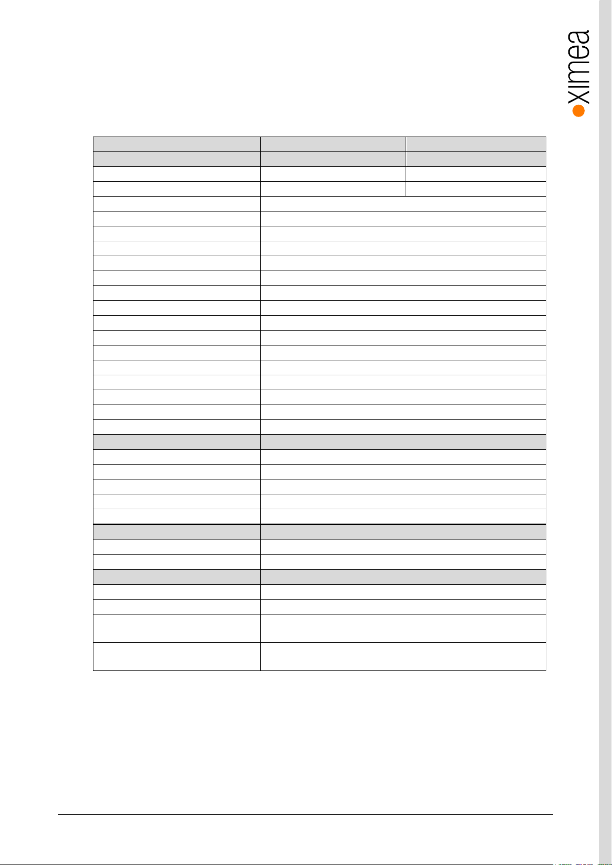
xiC model
MC023CG-SY
MC023MG-SY
Sensor parameter
Model name
IMX174LQJ-C
IMX174LLJ-C
Color filter
RGB Bayer mosaic
None
Type
Global shutter, overlap mode
Pixel Resolution (H × V) [pixel]
1936 x 1216
Active area size (H × V) [mm]
11.314 x 7.12
Sensor diagonal [mm]
13.39
Optical format [inch]
1/1.2
Pixel Size (H × V) [µm]
5.86 x 5.86
ADC resolution [bit]
10, 12
FWC [ke-]
30.5
Dynamic range [dB]
71.7
SNR Max [dB]
45
Conversion gain [e-/LSB12]
8.1
Dark noise [e-]
7.36
Dark current [e-/s]
3
DSNU [e-]
1.1
PRNU %
0.4
Linearity [%]
0.5
Camera parameters
Digitization [bit]
10, 12
Supported bit resolutions [bit/pixel]
8, 10, 12
Exposure time (EXP)
19µs to 30sec, in steps of 4.96µs 1
Variable Gain Range (VGA) [dB]
0-24
Refresh rate (MRR) [fps]
165
Power consumption
typical [W]
2.2
Maximum [W]
2.5
Dimensions/Mass
height [mm]
26.4
width [mm]
26.4
depth (-TC/-UB/-FL/-FV) [mm]
42.3/42.0/28.9/29.4(with C/CS Mount module B)
37.3/37.0/23.9/24.4 (without C/CS Mount module B)
mass (-TC/-UB/-FL/-FV) [g]
38.3/37.5/28.3/28.3 (with C/CS Mount module B)
34.1/33.3/24.1/24.1 (without C/CS Mount module B)
3.5. Model Specific Characteristics
3.5.1. MC023xG-SY
3.5.1.1. Sensor and camera parameters
table 3-6, MC023xG-SY, sensor and camera parameters
Notes:
1) Defined for maximal bandwidth. Minimal Exposure and exposure step (Line Period) could be calculated in:
Camera performance calculator:
https://www.ximea.com/support/attachments/download/7828/Camera_Performance_Calculator.xlsm
Page 24
xiC - Technical Manual Version 1.16
24
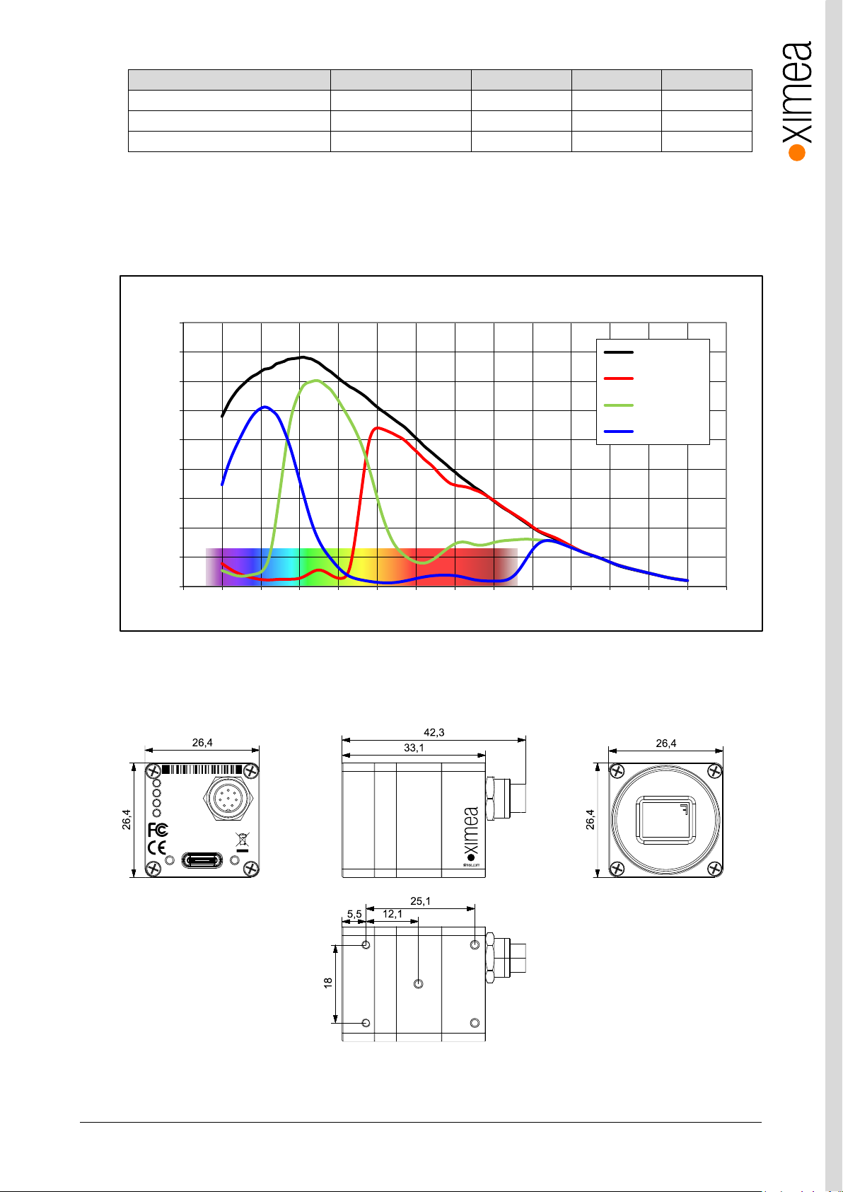
Supported standard readout modes
Binning/skipping
pixels
fps
Bit/px
0
1x1
1936 x 1216
165
8
1
1x1
1936 x 1216
129
10
2
1x1
1936 x 1216
108
12
0%
10%
20%
30%
40%
50%
60%
70%
80%
90%
350 400 450 500 550 600 650 700 750 800 850 900 950 1000 1050
Quantum Efficiency (%)
Wavelength (nm)
IMX174 - Spectral Response
Monochrome
Red Bayer
Green Bayer
Blue Bayer
5 x M2 max
. depth 2 mm
mod.
: 25.0 x 18 mm (12.1 x 9 mm) C-mount
20.0 x 18 mm (7.1 x 9 mm) CS-mount
C/CS-Mount module
A
Remove this module
for CS mount back
focal distance
C/CS-Mount module B
xiC
1
2
3
4
MC023CG-SY-TC
CACAC1623001
Made in SK
IO
AUX
power
USB 3.1 Gen 1
Type C
xiC
USB 3.1
Gen 1
USB3VISION
table 3-7, MC023xG-SY, supported standard readout modes
3.5.1.2. Quantum efficiency curves [%]
figure 3-6, IMX174-mono, quantum efficiency curve, ©SONY
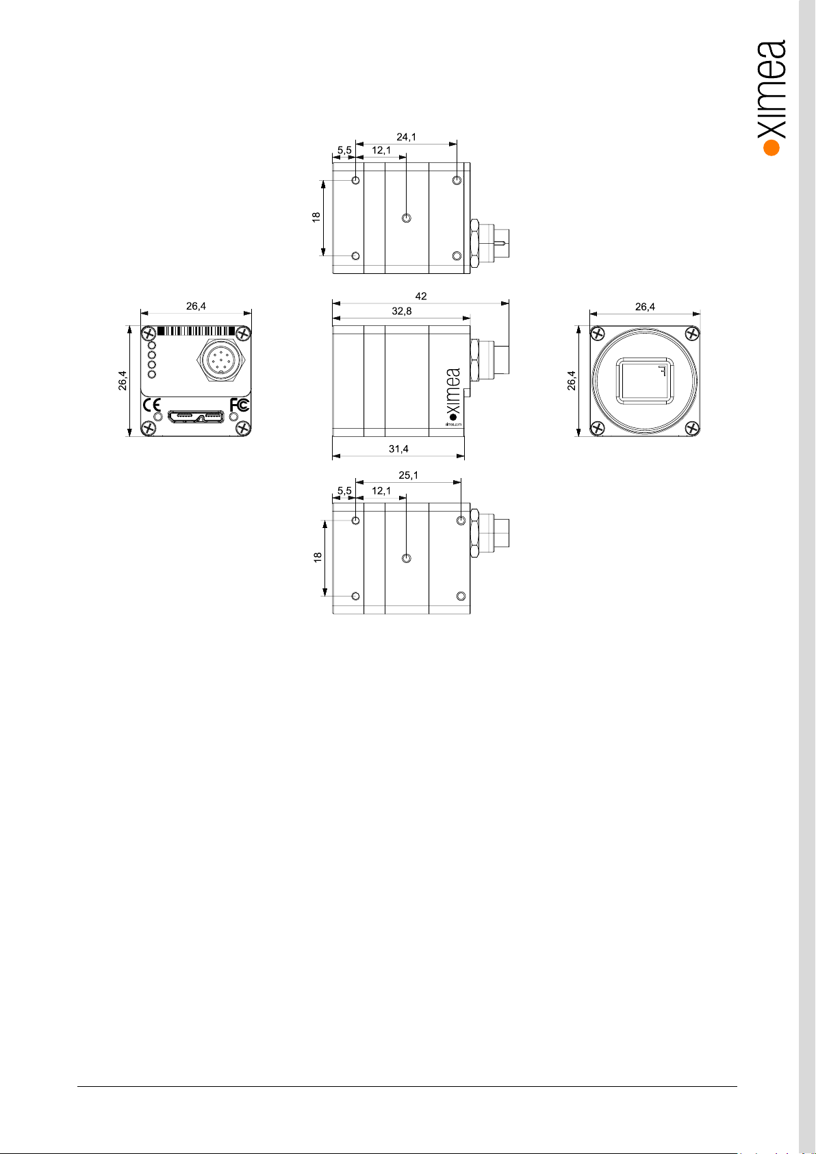
3.5.1.3. Dimensional drawings MC023xG-SY-TC (C-mount [with C/CS mount module B])
figure 3-7, dimensional drawing MC023xG-SY-TC, C-Mount housing
Page 25
xiC - Technical Manual Version 1.16
25
5 x M2 max
. depth 2 mm
mod.
: 25.1(24.1) x 18 mm (12.1 x 9 mm) C-mount
20.1(19.1) x 18 mm (7.1 x 9 mm) CS-mount
C/CS-Mount module
A
Remove this module
for CS mount back
focal distance
C/CS-Mount module B
xiC
1
2
3
4
MC023CG-SY-UB
CACAU1623001 Made in SK
IO
AUX
power
For use with XIMEAapproved conn ection cables only.
USB 3.1 Gen 1
xiC
USB 3.1
Gen1
USB3VISION
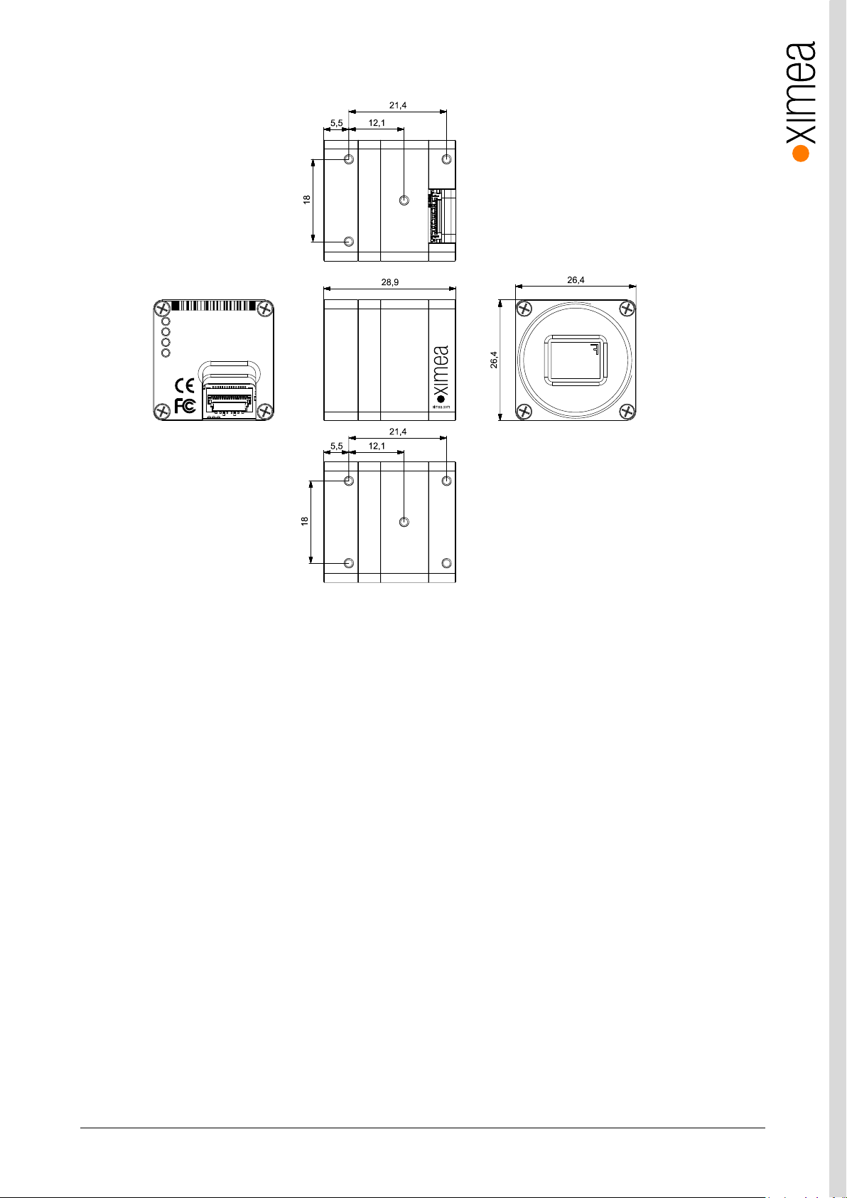
3.5.1.4. Dimensional drawings MC023xG-SY-UB (C-mount [with C/CS mount module B])
figure 3-8, dimensional drawing MC023xG-SY-UB, C-Mount housing
Page 26
xiC - Technical Manual Version 1.16
26
xiC
1
2
3
4
MC023CG-SY-FL
CACAF1623001
Made in SK
USB 3.1 Gen 1
xiC
USB 3.1
Gen 1
USB3VISION
5 x M2 max
. depth 2 mm
mod.
: 21.4 x 18 mm (12.1 x 9 mm) C-mount
16.4 x 18 mm (7.1 x 9 mm) CS-mount
C/CS-Mount module
A
Remove this module
for CS mount back
focal distance
C/CS-Mount module B
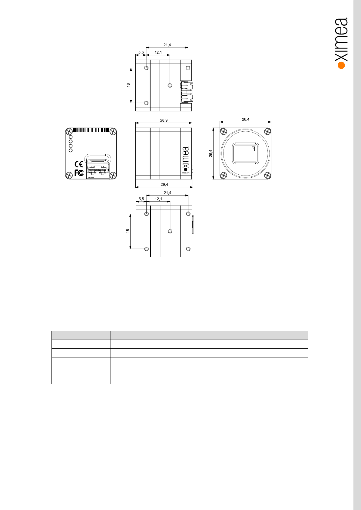
3.5.1.5. Dimensional drawings MC023xG-SY-FL (C-mount [with C/CS mount module B])
Figure 3-9 dimensional drawing MC023xG-SY-FL, C-Mount housing
Page 27
xiC - Technical Manual Version 1.16
27
feature
Note
Binning
No
Skipping
Not supported
ROI
Vertical cropping results in increased read speed, horizontal reduces data transfer
HW Trigger
Trigger with overlap (see 4.3.2.1 Triggered acquisition - )
HDR
Not available
xiC
1
2
3
4
MC023CG-SY-FV
CACAV1623001
Made in SK
USB 3.1 Gen 1
xiC
USB 3.1
Gen 1
USB3VISION
5 x M2 max
. depth 2 mm
mod.
: 21.4 x 18 mm (12.1 x 9 mm) C-mount
16.4 x 18 mm (7.1 x 9 mm) CS-mount
C/CS-Mount module
A
Remove this module
for CS mount back
focal distance
C/CS-Mount module B
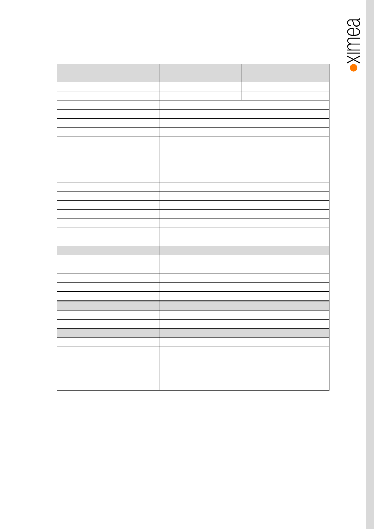
3.5.1.6. Dimensional drawings MC023xG-SY-FV (C-mount [with C/CS mount module B])
Figure 3-10 dimensional drawing MC023xG-SY-FV, C-Mount housing
3.5.1.7. Referenced documents
Sony Datasheet IMX174LQJ-C_E_TechnicalDatasheet_REv0.3 (01/06/14)
Sony Datasheet IMX174LLJ-C_E_data_sheet_E14315 (01/06/14)
3.5.1.8. Sensor features
table 3-8, sensor features available
Page 28
xiC - Technical Manual Version 1.16
28
xiC model
MC031CG-SY
MC031MG-SY
Sensor parameter
Model name
IMX252LQR-C
IMX252LLR-C
Color filter
RGB Bayer mosaic
None
Type
Global shutter, overlap mode
Pixel Resolution (H × V) [pixel]
2064 x 1544
Active area size (H × V) [mm]
7.12 x 5.33
Sensor diagonal [mm]
8.89
Optical format [inch]
1/1.8
Pixel Size (H × V) [µm]
3.45 × 3.45
ADC resolution [bit]
8, 10, 12
FWC [ke-]
9.9
Dynamic range [dB]
70.9
SNR Max [dB]
40.3
Conversion gain [e-/LSB12]
2.67
Dark noise [e-]
2.32
Dark current [e-/s]
2.1
DSNU [e-]
0.7
PRNU %
0.65
Linearity [%]
0.5
Camera parameters
Digitization [bit]
83, 10, 12
Supported bit resolutions [bit/pixel]
8, 10, 12
Exposure time (EXP)
1µs2 to 30sec, in steps of 5.29µs 1
Variable Gain Range (VGA) [dB]
0-24
Refresh rate (MRR) [fps]
122
Power consumption
typical [W]
2.75
Maximum [W]
2.85
Dimensions/Mass
height [mm]
26.4
width [mm]
26.4
depth (-TC/-UB/-FL/-FV) [mm]
42.2/41.9/28.8/29.3(with C/CS Mount module B)
37.3/36.9/23.8/24.3 (without C/CS Mount module B)
mass (-TC/-UB/-FL/-FV) [g]
38.3/37.5/28.3/28.3 (with C/CS Mount module B)
34.1/33.3/24.1/24.1 (without C/CS Mount module B)
3.5.2. MC031xG-SY
3.5.2.1. Sensor and camera parameters
table 3-9, MC031xG-SY, sensor and camera parameters
Notes:
1) Defined for maximal bandwidth. Minimal Exposure and exposure step (Line Period) could be calculated in:
Camera performance calculator:
https://www.ximea.com/support/attachments/download/7828/Camera_Performance_Calculator.xlsm
2) From 1 µs to 14 µs the step is 1µs and the sensor is operating in special mode. This exposure times are not
achievable for exposure controlled by trigger pulse length.
3) Saturation level in 8bit digitization is only ¼ of 10bit and 12bit mode (see 4.2.5 Digitization bit depth)
Page 29
xiC - Technical Manual Version 1.16
29
Color model
Mono model
Binning/skipping (H X V)
pixels
fps
Bit/px
Yes
Yes
1x1 / 1x1
2064 x 1544
122
8
Yes
Yes
1x1 / 1x1
2064 x 1544
96
10
Yes
Yes
1x1 / 1x1
2064 x 1544
80
12
Yes
Yes
1x1 / 1x2
2064 x 772
241
8
Yes
Yes
1x1 / 2x1
1032 x 1544
218 8 Yes
Yes
1x1 / 2x2
1032 x 772
426
8
No
Yes
1x2 / 1x1
2064 x 772
241 8 No
Yes
1x2 / 2x1
1032 x 772
426 8 Yes
Yes
1x1 / 2x2
1032 x 772
377
10
Yes
Yes
1x1 / 2x2
1032 x 772
233
12
0%
10%
20%
30%
40%
50%
60%
70%
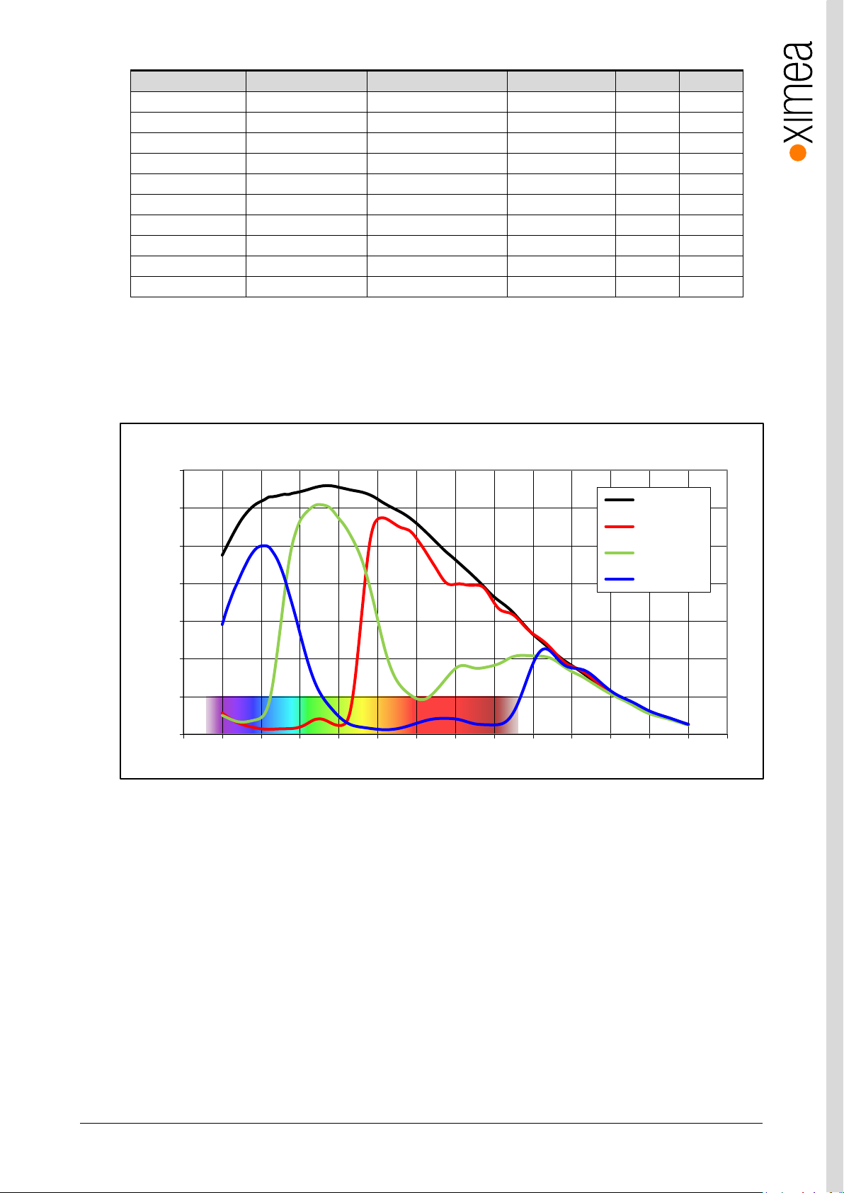
350 400 450 500 550 600 650 700 750 800 850 900 950 1000 1050
Quantum Efficiency (%)
Wavelength (nm)
IMX252- Spectral Response
Monochrome
Red Bayer
Green Bayer
Blue Bayer
table 3-10, MC031xG-SY, supported standard readout modes
3.5.2.2. Quantum efficiency curves [%]
figure 3-11, IMX252-mono and color, quantum efficiency curves, ©SONY
Page 30
xiC - Technical Manual Version 1.16
30
5 x M2 max
. depth 2 mm
mod.
: 25.0 x 18 mm (12.1 x 9 mm) C-mount
20.0 x 18 mm (7.1 x 9 mm) CS-mount
C/CS-Mount module
A
Remove this module
for CS mount back
focal distance
C/CS-Mount module B
xiC
USB 3.1
Gen 1
USB3VISION
xiC
1
2
3
4
MC031CG-SY-TC
CECAC1623001
Made in SK
IO
AUX
power
USB 3.1 Gen 1
Type C
5 x M2 max
. depth 2 mm
mod.
: 25.0(24.0) x 18 mm (12.1 x 9 mm) C-mount
20.0(19.0) x 18 mm (7.1 x 9 mm) CS-mount
C/CS-Mount module
A
Remove this module
for CS mount back
focal distance
C/CS-Mount module B
xiC
USB 3.1
Gen 1
USB3VISION
xiC
1
2
3
4
MC031CG-SY-UB
CECAU1623001 Made in SK
IO
AUX
power
For use with XIMEAapproved conne ction cables only.
USB 3.1 Gen 1
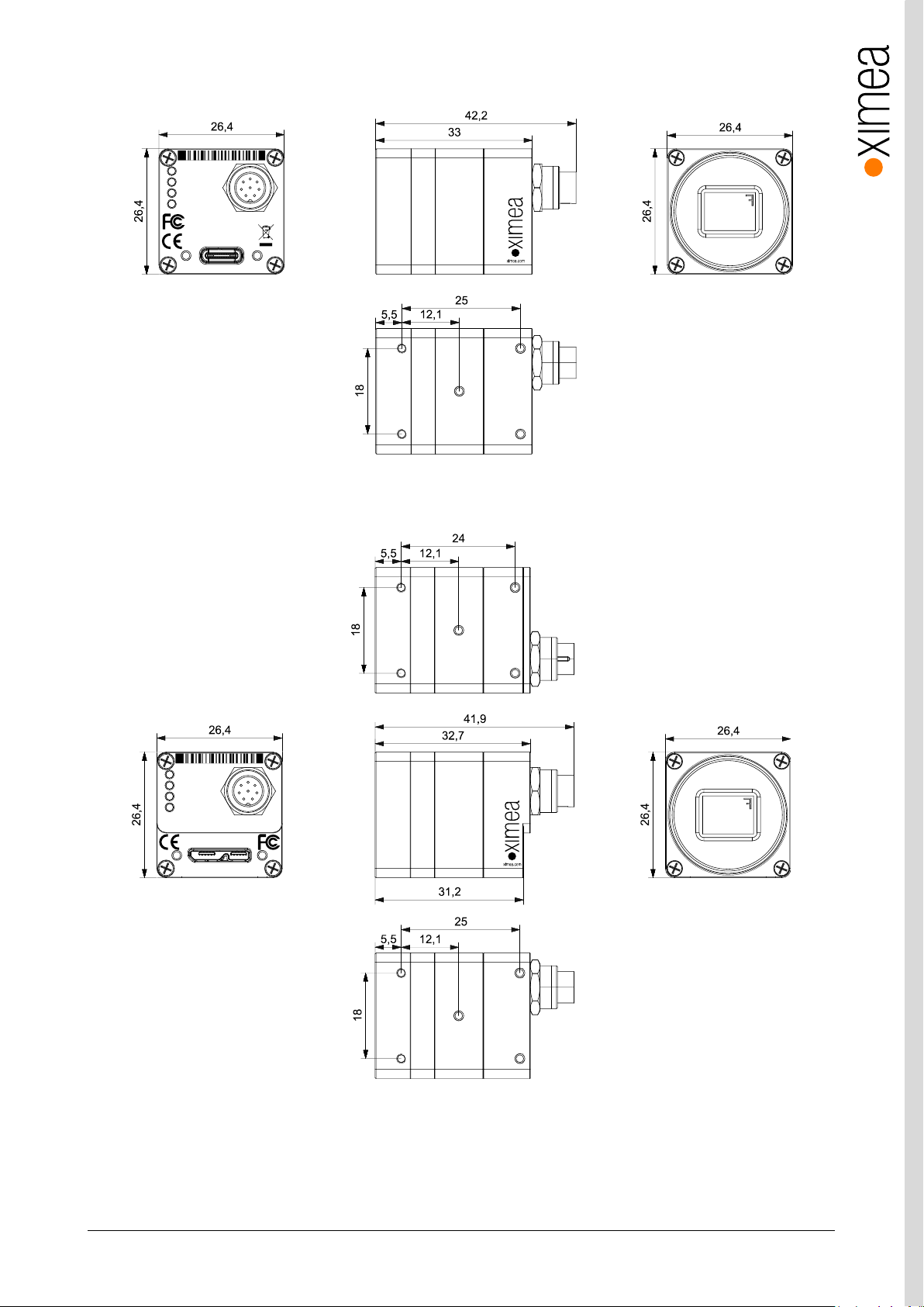
3.5.2.3. Dimensional drawings MC031xG-SY-TC (C-mount [with C/CS mount module B])
figure 3-12, dimensional drawing MC031xG-TC, C-Mount housing
3.5.2.4. Dimensional drawings MC031xG-SY-UB (C-mount [with C/CS mount module B])
Figure 3-13, dimensional drawing MC031xG-SY-UB, C-mount housing
Page 31
xiC - Technical Manual Version 1.16
31
xiC
1
2
3
4
MC031CG-SY-FL
CECAF1623001
Made in SK
USB 3.1 Gen 1
xiC
USB 3.1
Gen 1
USB3VISION
5 x M2 max
. depth 2 mm
mod.
: 21.3 x 18 mm (12.1 x 9 mm) C-mount
16.3 x 18 mm (7.1 x 9 mm) CS-mount
C/CS-Mount module
A
Remove this module
for CS mount back
focal distance
C/CS-Mount module B
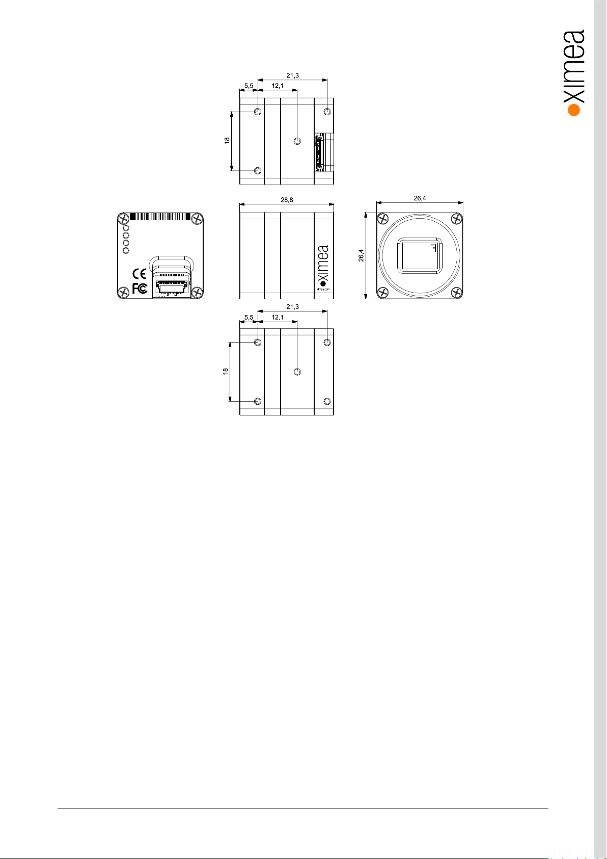
3.5.2.5. Dimensional drawings MC031xG-SY-FL (C-mount [with C/CS mount module B])
Figure 3-14, dimensional drawing MC031xG-SY-FL, C-mount housing
Page 32
xiC - Technical Manual Version 1.16
32
feature
Note
Binning
Yes, 1x2 (H x V) binning supported on monochrome only.
Skipping
Yes, 2x2
ROI
Vertical cropping results in increased read speed, horizontal reduces data transfer
HW Trigger
Trigger with overlap usable (see 4.3.2.1 Triggered acquisition - )
HDR
Currently not supported
xiC
1
2
3
4
MC031CG-SY-FV
CECAV1623001
Made in SK
USB 3.1 Gen 1
xiC
USB 3.1
Gen 1
USB3VISION
5 x M2 max
. depth 2 mm
mod.
: 21.3 x 18 mm (12.1 x 9 mm) C-mount
16.3 x 18 mm (7.1 x 9 mm) CS-mount
C/CS-Mount module
A
Remove this module
for CS mount back
focal distance
C/CS-Mount module B
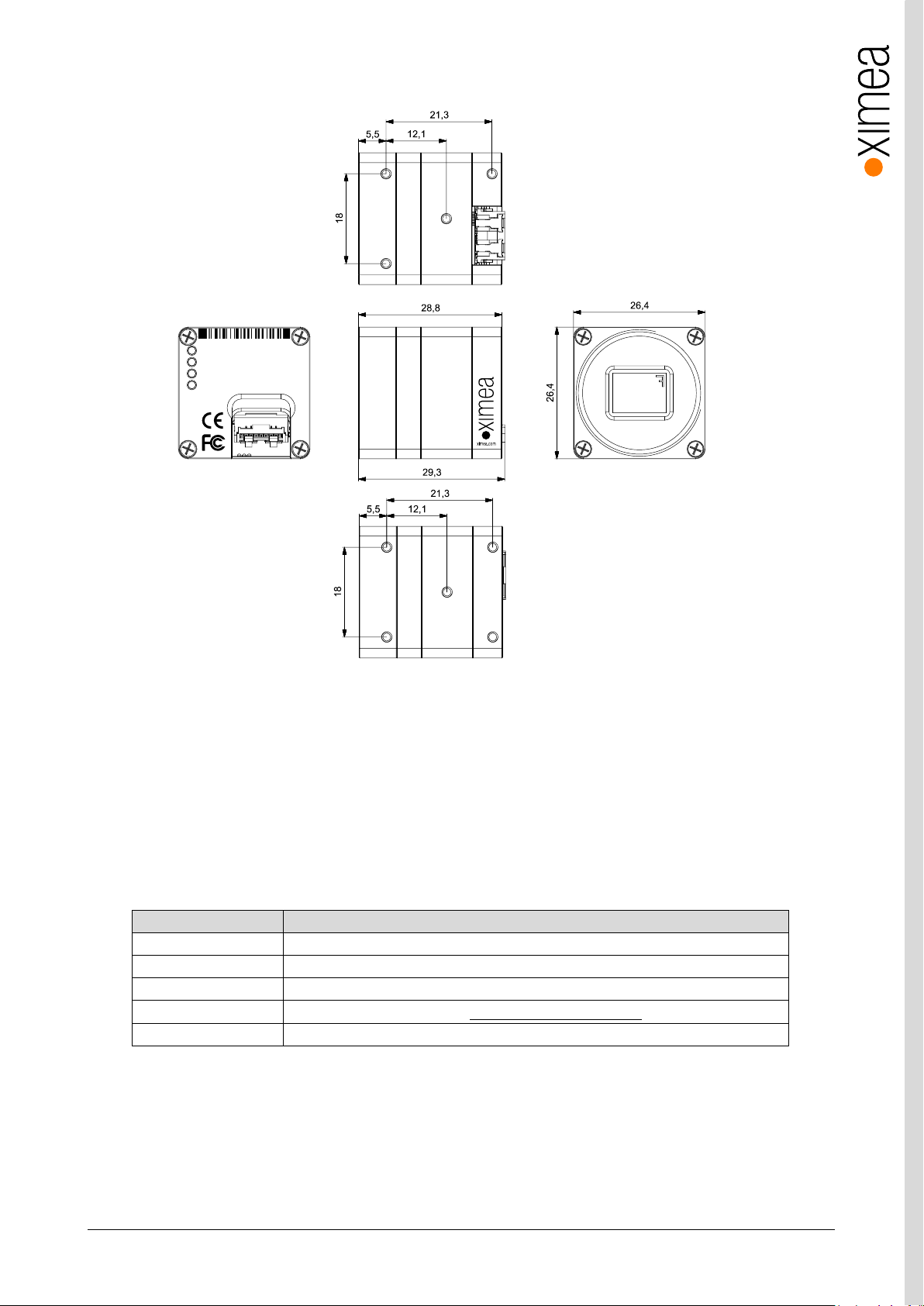
3.5.2.6. Dimensional drawings MC031xG-SY-FV (C-mount [with C/CS mount module B])
figure 3-15, dimensional drawing MC031xG-SY-FV, C-mount housing
3.5.2.7. Referenced documents
Sony Datasheet IMX252LLR-C_Data_Sheet(E)_E15903 (03/09/15)
Sony Datasheet IMX252LQR-C_Data_Sheet(E)_E15911 (11/09/15)
3.5.2.8. Sensor features
table 3-11, sensor features available
Page 33
xiC - Technical Manual Version 1.16
33
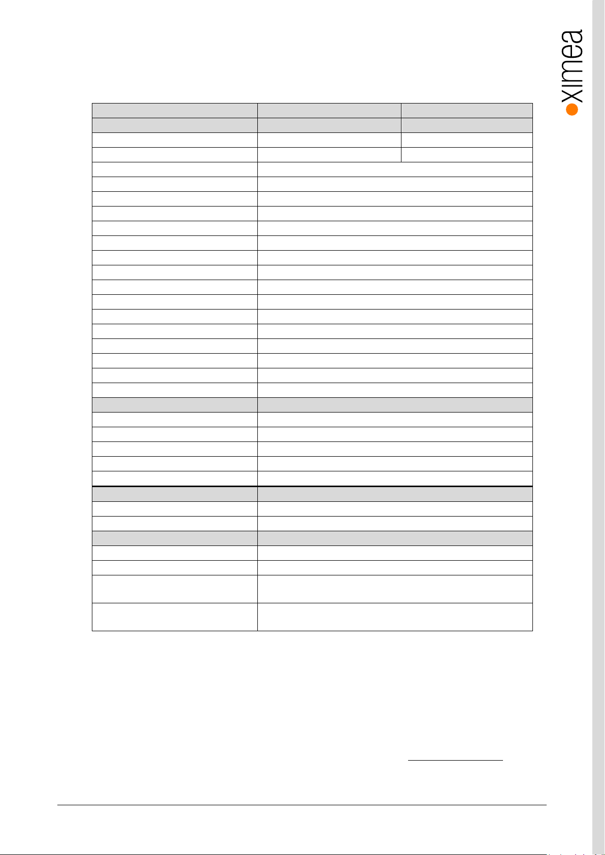
xiC model
MC050CG-SY
MC050MG-SY
Sensor parameter
Model name
IMX250LQR-C
IMX250LLR-C
Color filter
RGB Bayer mosaic
None
Type
Global shutter, overlap mode
Pixel Resolution (H × V) [pixel]
2464 x 2056
Active area size (H × V) [mm]
8.5 x 7.09
Sensor diagonal [mm]
11.1
Optical format [inch]
2/3
Pixel Size (H × V) [µm]
3.45 x 3.45
ADC resolution [bit]
8, 10, 12
FWC [ke-]
9.8
Dynamic range [dB]
70.8
SNR Max [dB]
40.3
Conversion gain [e-/LSB12]
2.66
Dark noise [e-]
2.32
Dark current [e-/s]
3.9
DSNU [e-]
0.75
PRNU %
0.61
Linearity [%]
0.5
Camera parameters
Digitization [bit]
83, 10, 12
Supported bit resolutions [bit/pixel]
8, 10, 12
Exposure time (EXP)
1µs2 to 30sec, in steps of 6.32µs
1
Variable Gain Range (VGA) [dB]
0-24
Refresh rate (MRR) [fps]
76
Power consumption
typical [W]
2.85
Maximum [W]
3.0
Dimensions/Mass
height [mm]
26.4
width [mm]
26.4
depth (-TC/-UB/-FL/-FV) [mm]
42.2/41.9/28.8/29.3(with C/CS Mount module B)
37.3/36.9/23.8/24.3 (without C/CS Mount module B)
mass (-TC/-UB/-FL/-FV) [g]
38.3/37.5/28.3/28.3 (with C/CS Mount module B)
34.1/33.3/24.1/24.1 (without C/CS Mount module B)
3.5.3. MC050xG-SY
3.5.3.1. Sensor and camera parameters
table 3-12, MC050xG-SY, sensor and camera parameters
Notes:
1) Defined for maximal bandwidth. Minimal Exposure and exposure step (Line Period) could be calculated in:
Camera performance calculator:
https://www.ximea.com/support/attachments/download/7828/Camera_Performance_Calculator.xlsm
2) From 1 µs to 14 µs the step is 1µs and the sensor is operating in special mode. This exposure times are not
achievable for exposure controlled by trigger pulse length.
3) Saturation level in 8bit digitization is only ¼ of 10bit and 12bit mode (see 4.2.5 Digitization bit depth)
Page 34
xiC - Technical Manual Version 1.16
34
Color model
Mono mode
Binning/skipping (H X V)
pixels
fps
Bit/px
Yes
Yes
1x1 / 1x1
2464 x 2056
76
8
Yes
Yes
1x1 / 1x1
2464 x 2056
60
10
Yes
Yes
1x1 / 1x1
2464 x 2056
50
12
Yes
Yes
1x1 / 1x2
2464 x 1028
152
8
Yes
Yes
1x1 / 2x1
1232 x 2056
152 8 Yes
Yes
1x1 / 2x2
1232 x 1028
304
8
No
Yes
1x2 / 1x1
2464 x 1028
152 8 No
Yes
1x2 / 2x1
1232 x 1028
304 8 Yes
Yes
1x1 / 2x2
1232 x 1028
243
10
Yes
Yes
1x1 / 2x2
1232 x 1028
177
12
0%
10%
20%
30%
40%
50%
60%
70%
350 400 450 500 550 600 650 700 750 800 850 900 950 1000 1050
Quantum Efficiency (%)
Wavelength (nm)
IMX250- Spectral Response
Monochrome
Red Bayer
Green Bayer
Blue Bayer
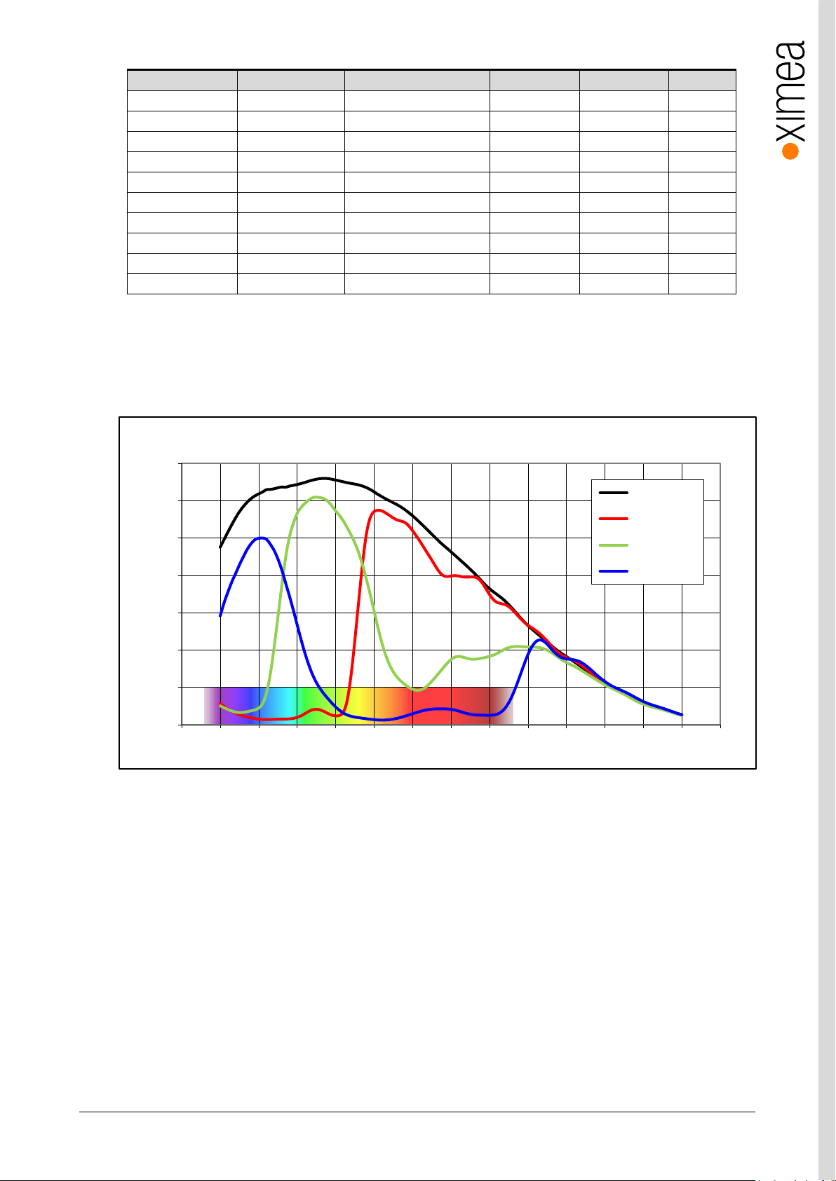
table 3-13, MC050xG-SY, supported standard readout modes
3.5.3.2. Quantum efficiency curves [%]
figure 3-16 IMX250 mono and color, quantum efficiency curves, ©SONY
Page 35
xiC - Technical Manual Version 1.16
35
5 x M2 max
. depth 2 mm
mod.
: 25.0 x 18 mm (12.1 x 9 mm) C-mount
20.0 x 18 mm (7.1 x 9 mm) CS-mount
C/CS-Mount module
A
Remove this module
for CS mount back
focal distance
C/CS-Mount module B
xiC
USB 3.1
Gen 1
USB3VISION
xiC
1
2
3
4
MC050CG-SY-TC
CICAC1623001
Made in SK
IO
AUX
power
USB 3.1 Gen 1
Type C
5 x M2 max
. depth 2 mm
mod.
: 25.0(24.0) x 18 mm (12.1 x 9 mm) C-mount
20.0(19.0) x 18 mm (7.1 x 9 mm) CS-mount
C/CS-Mount module
A
Remove this module
for CS mount back
focal distance
C/CS-Mount module B
xiC
USB 3.1
Gen 1
USB3VISION
xiC
1
2
3
4
MC050CG-SY-UB
CICAU1623001 Made in SK
IO
AUX
power
For use with XIMEAapproved conne ction cables only.
USB 3.1 Gen 1
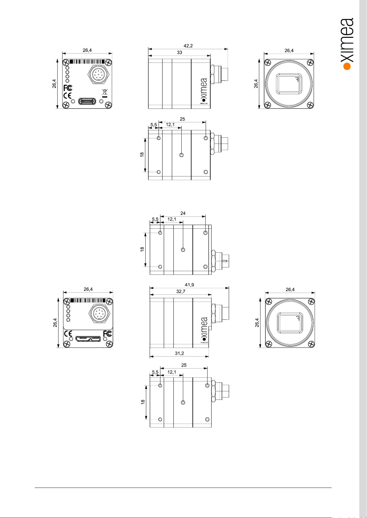
3.5.3.3. Dimensional drawings MC050xG-SY-TC (C-mount [with C/CS mount module B])
figure 3-17, dimensional drawing MC050xG-SY-TC, C-Mount housing
3.5.3.4. Dimensional drawings MC050xG-SY-UB (C-mount [with C/CS mount module B])
figure 3-18, dimensional drawing MC050xG-SY-UB, C-Mount housing
Page 36
xiC - Technical Manual Version 1.16
36
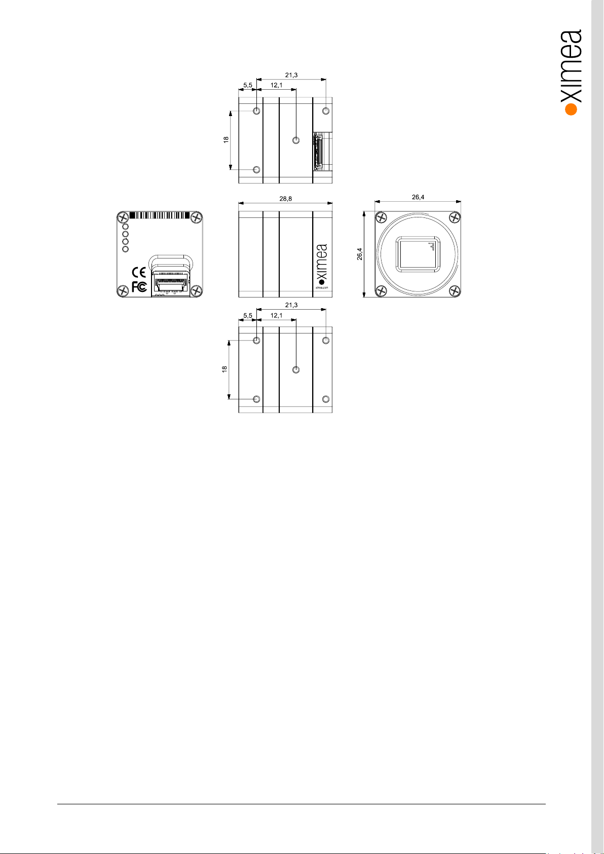
xiC
1
2
3
4
MC050CG-SY-FL
CICAF1623001
Made in SK
USB 3.1 Gen 1
xiC
USB 3.1
Gen 1
USB3VISION
5 x M2 max
. depth 2 mm
mod.
: 21.3 x 18 mm (12.1 x 9 mm) C-mount
16.3 x 18 mm (7.1 x 9 mm) CS-mount
C/CS-Mount module
A
Remove this module
for CS mount back
focal distance
C/CS-Mount module B
3.5.3.5. Dimensional drawings MC050xG-SY-FL (C-mount [with C/CS mount module B])
Figure 3-19, dimensional drawing MC050xG-SY-FL, C-Mount housing
Page 37
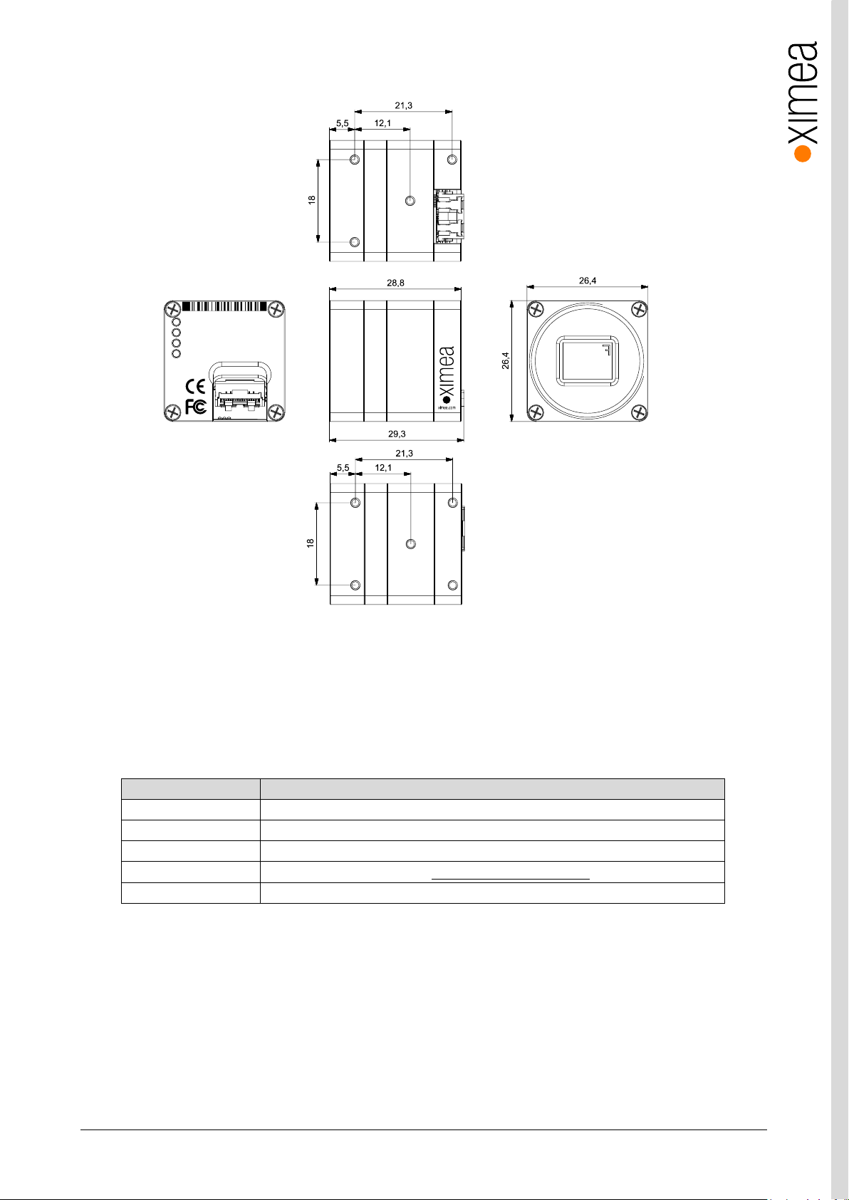
xiC - Technical Manual Version 1.16
37
feature
Note
Binning
Yes, 1x2 (H x V) binning supported on monochrome only.
Skipping
Yes, 2x2
ROI
Vertical cropping results in increased read speed, horizontal reduces data transfer
HW Trigger
Trigger with overlap usable (see 4.3.2.1 Triggered acquisition - )
HDR
Not available
xiC
1
2
3
4
MC050CG-SY-FV
CICAV1623001
Made in SK
USB 3.1 Gen 1
xiC
USB 3.1
Gen 1
USB3VISION
5 x M2 max
. depth 2 mm
mod.
: 21.3 x 18 mm (12.1 x 9 mm) C-mount
16.3 x 18 mm (7.1 x 9 mm) CS-mount
C/CS-Mount module
A
Remove this module
for CS mount back
focal distance
C/CS-Mount module B
3.5.3.6. Dimensional drawings MC050xG-SY-FV (C-mount [with C/CS mount module B])
Figure 3-20, dimensional drawing MC050xG-SY-FV, C-Mount housing
3.5.3.7. Referenced documents
Sony Datasheet IMX250LLR-C_Data_Sheet(E)_E15902 (02/09/15)
Sony Datasheet IMX250LQR-C_Data_Sheet(E)_E15910 (10/09/15)
3.5.3.8. Sensor features
table 3-14, sensor features available
Page 38
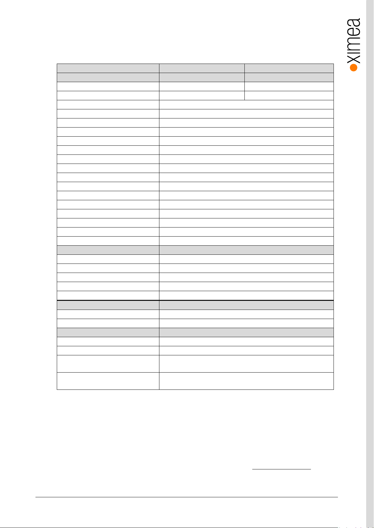
xiC - Technical Manual Version 1.16
38
xiC model
MC089CG-SY
MC089MG-SY
Sensor parameter
Model name
IMX255LQR-C
IMX255LLR-C
Color filter
RGB Bayer mosaic
None
Type
Global shutter, overlap mode
Pixel Resolution (H × V) [pixel]
4112 x 2176
Active area size (H × V) [mm]
14.2 x 7.5
Sensor diagonal [mm]
16
Optical format [inch]
1”
Pixel Size (H × V) [µm]
3.45 x 3.45
ADC resolution [bit]
8, 10, 12
FWC [ke-]
9.8
Dynamic range [dB]
70.5
SNR Max [dB]
40.3
Conversion gain [e-/LSB12]
2.67
Dark noise [e-]
2.4
Dark current [e-/s]
3.9
DSNU [e-]
0.75
PRNU %
0.61
Linearity [%]
0.5
Camera parameters
Digitization [bit]
83, 10, 12
Supported bit resolutions [bit/pixel]
8, 10, 12
Exposure time (EXP) 1µs2 to 30sec, in steps of 10.54µs
1
Variable Gain Range (VGA) [dB]
0-24
Refresh rate (MRR) [fps]
43
Power consumption
typical [W]
3.3
Maximum [W]
3.5
Dimensions/Mass
height [mm]
26.4
width [mm]
26.4
depth (-TC/-UB/-FL/-FV) [mm]
42.3/42.0/28.9/29.4(with C/CS Mount module B)
37.3/37.0/23.9/24.4 (without C/CS Mount module B)
mass (-TC/-UB/-FL/-FV) [g]
38.3/37.5/28.5/28.5 (with C/CS Mount module B)
34.1/33.3/24.3/24.3 (without C/CS Mount module B)
3.5.4. MC089xG-SY
3.5.4.1. Sensor and camera parameters
table 3-15, MC089xG-SY, sensor and camera parameters
Notes:
1) Defined for maximal bandwidth. Minimal Exposure and exposure step (Line Period) could be calculated in:
Camera performance calculator:
https://www.ximea.com/support/attachments/download/7828/Camera_Performance_Calculator.xlsm
2) From 1 µs to 14 µs the step is 1µs and the sensor is operating in special mode. This exposure times are not
achievable for exposure controlled by trigger pulse length.
3) Saturation level in 8bit digitization is only ¼ of 10bit and 12bit mode (see 4.2.5 Digitization bit depth)
Page 39
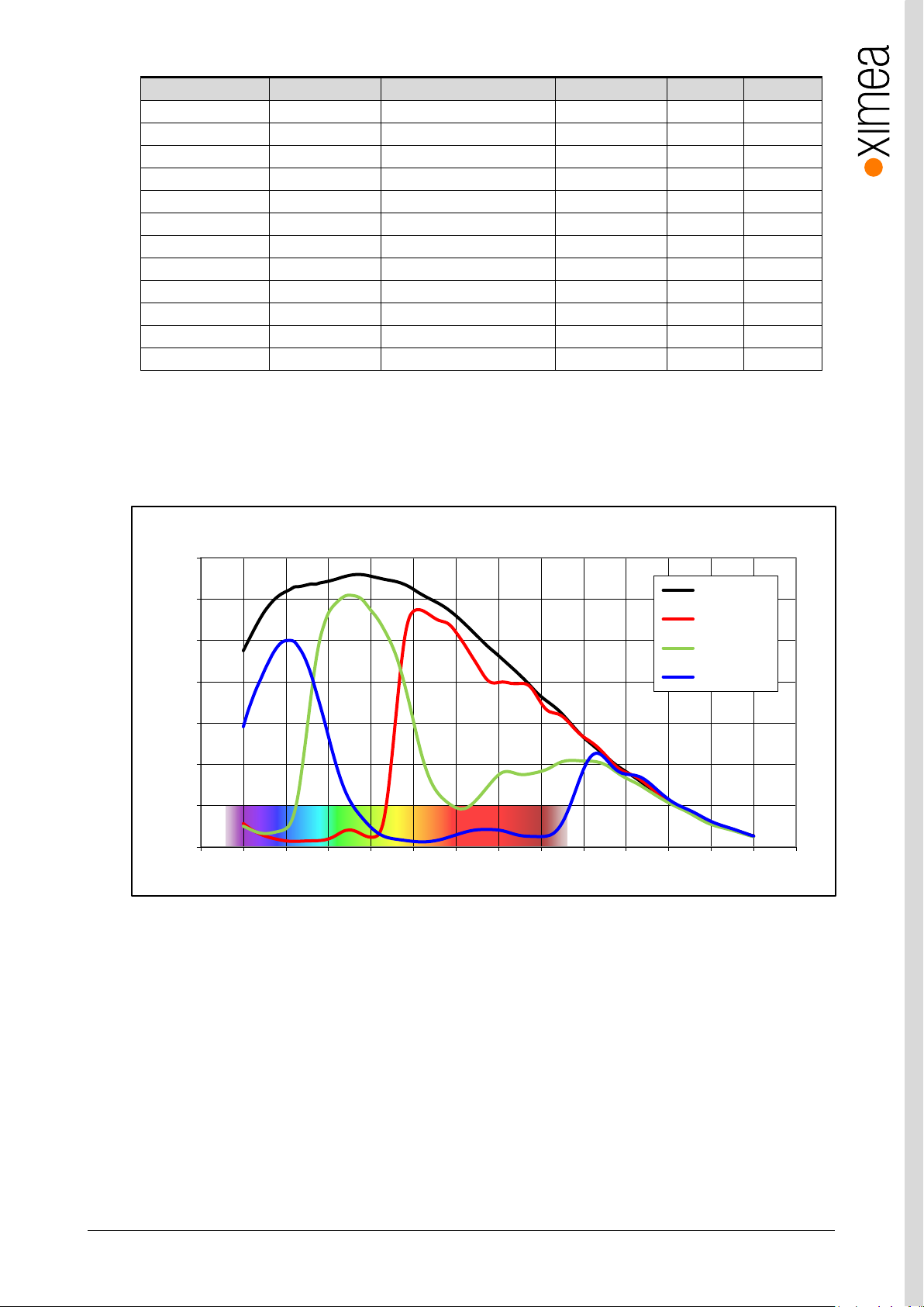
xiC - Technical Manual Version 1.16
39
Color model
Mono mode
Binning/skipping (H X V)
pixels
fps
Bit/px
Yes
Yes
1x1 / 1x1
4112 x 2176
43
8
Yes
Yes
1x1 / 1x1
4112 x 2176
34
10
Yes
Yes
1x1 / 1x1
4112 x 2176
28
12
Yes
Yes
1x1 / 1x2
4112 x 1088
86
8
Yes
Yes
1x1 / 2x1
2056 x 2176
86 8 Yes
Yes
1x1 / 2x2
2056 x 1088
172
8
No
Yes
1x2 / 1x1
4112 x 1088
86 8 No
Yes
2x2 / 1x1
2056 x 1088
172 8 No
Yes
2x2 / 1x1
2056 x 1088
137
10
No
Yes
2x2 / 1x1
2056 x 1088
114
12
Yes
Yes
1x1 / 2x2
2056 x 1088
137
10
Yes
Yes
1x1 / 2x2
2056 x 1088
114
12
0%
10%
20%
30%
40%
50%
60%
70%
350 400 450 500 550 600 650 700 750 800 850 900 950 1000 1050
Quantum Efficiency (%)
Wavelength (nm)
IMX255- Spectral Response
Monochrome
Red Bayer
Green Bayer
Blue Bayer
table 3-16, MC089xG-SY, supported standard readout modes
3.5.4.2. Quantum efficiency curves [%]
figure 3-21, IMX255 mono and color, quantum efficiency curve, ©SONY
Page 40
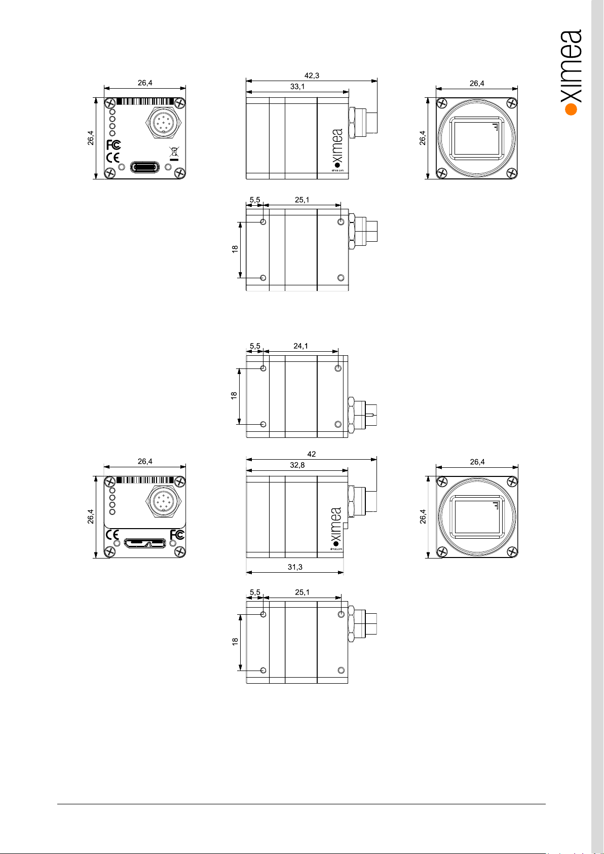
xiC - Technical Manual Version 1.16
40
4 x M2 max
. depth 2 mm
mod.
: 25.1 x 18 mm C-mount
20.1 x 18 mm CS-mount
C/CS-Mount module
A
Remove this module
for CS mount back
focal distance
C/CS-Mount module B
xiC
USB 3.1
Gen 1
USB3VISION
xiC
1
2
3
4
MC089CG-SY-TC
COCAC1623001
Made in SK
IO
AUX
power
USB 3.1 Gen 1
Type C
4 x M2 max
. depth 2 mm
mod.
: 25.1(24.1) x 18 mm C-mount
20.1 x 18 mm CS-mount
C/CS-Mount module
A
Remove this module
for CS mount back
focal distance
C/CS-Mount module B
xiC
USB 3.1
Gen 1
USB3VISION
xiC
1
2
3
4
MC089CG-SY-UB
COCAU1623001 Made in SK
IO
AUX
power
For use with XIMEAapproved conn ection cables only.
USB 3.1 Gen 1
3.5.4.3. Dimensional drawings MC089xG-SY-TC (C-mount [with C/CS mount module B])
figure 3-22, dimensional drawing MC089xG-SY-TC, C-Mount housing
3.5.4.4. Dimensional drawings MC089xG-SY-UB (C-mount [with C/CS mount module B])
figure 3-23, dimensional drawing MC089xG-SY-UB, C-Mount housing
Page 41
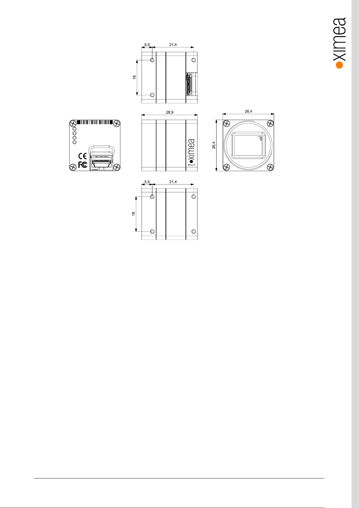
xiC - Technical Manual Version 1.16
41
xiC
1
2
3
4
MC089CG-SY-FL
COCAF1623001
Made in SK
USB 3.1 Gen 1d
xiC
USB 3.1
Gen 1
USB3VISION
4 x M2 max
. depth 2 mm
mod.
: 21.4 x 18 mm C-mount
16.4 x 18 mm CS-mount
C/CS-Mount module
A
Remove this module
for CS mount back
focal distance
C/CS-Mount module B
3.5.4.5. Dimensional drawings MC089xG-SY-FL (C-mount [with C/CS mount module B])
Figure 3-24, dimensional drawing MC089xG-SY-FL, C-Mount housing
Page 42
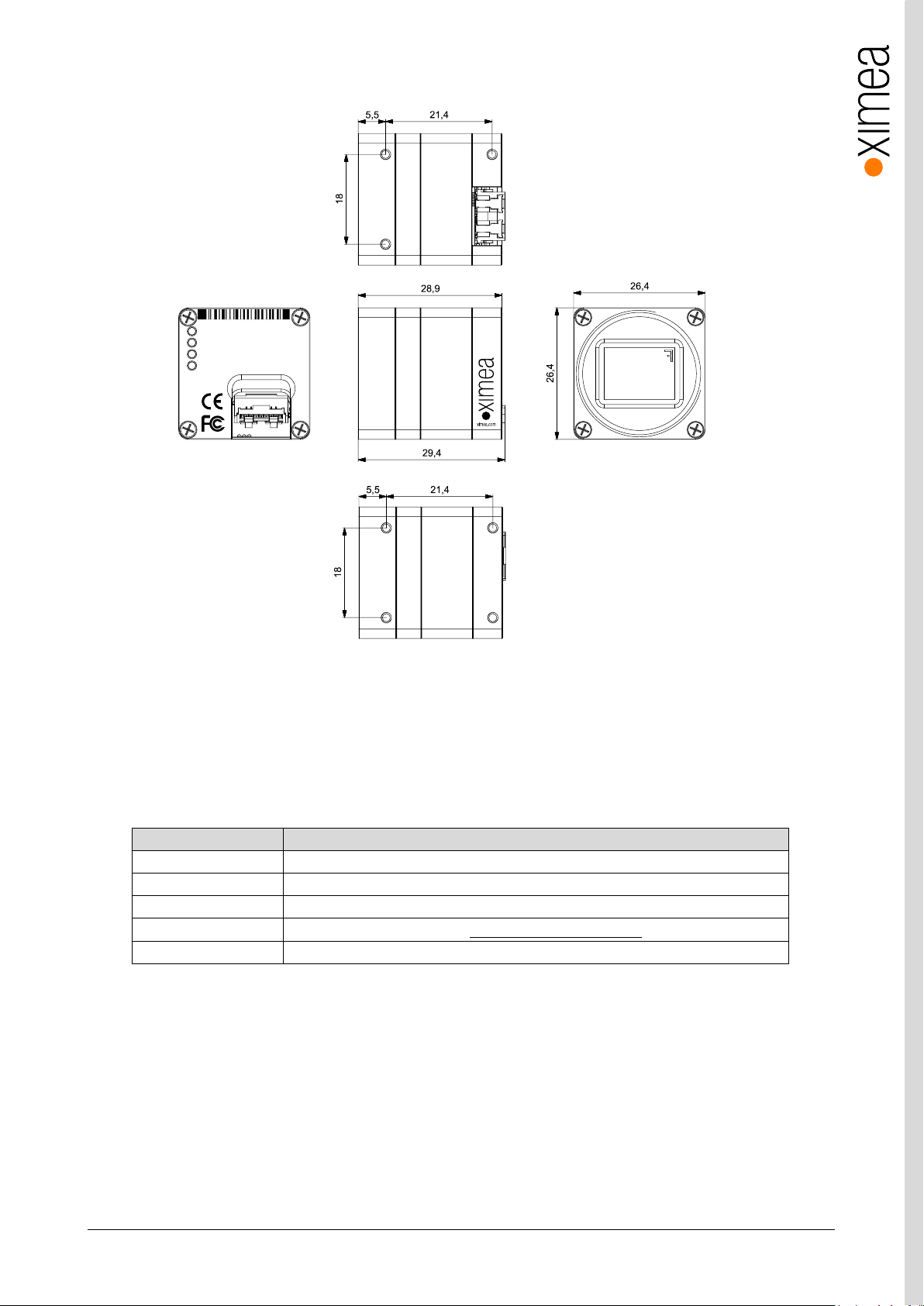
xiC - Technical Manual Version 1.16
42
feature
Note
Binning
Yes, up to 2x2 binning supported on monochrome only.
Skipping
Yes, up to 1x2
ROI
Vertical cropping results in increased read speed, horizontal reduces data transfer
HW Trigger
Trigger with overlap usable (see 4.3.2.1 Triggered acquisition - )
HDR
Not available
xiC
1
2
3
4
MC089CG-SY-FV
COCAV1623001
Made in SK
USB 3.1 Gen 1
xiC
USB 3.1
Gen 1
USB3VISION
4 x M2 max
. depth 2 mm
mod.
: 21.4 x 18 mm C-mount
16.4 x 18 mm CS-mount
C/CS-Mount module
A
Remove this module
for CS mount back
focal distance
C/CS-Mount module B
3.5.4.6. Dimensional drawings MC089xG-SY-FV (C-mount [with C/CS mount module B])
Figure 3-25, dimensional drawing MC089xG-SY-FV, C-Mount housing
3.5.4.7. Referenced documents
Sony Datasheet IMX255LLR-C_TechnicalDatasheet_E_Rev0.1 (29/01/16)
Sony Datasheet IMX255LQR-C_TechnicalDatasheet_E_Rev0.1 (29/01/16)
3.5.4.8. Sensor features
table 3-17, sensor features available
Page 43
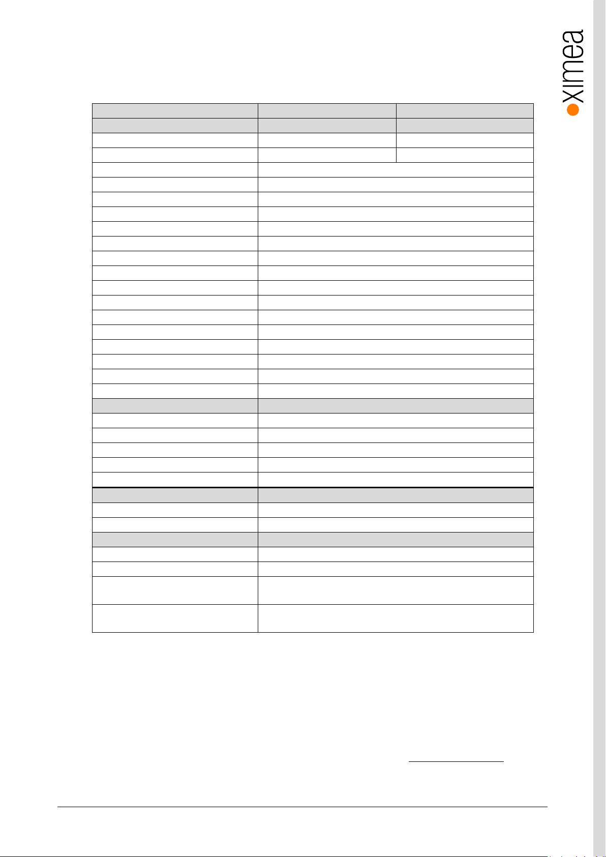
xiC - Technical Manual Version 1.16
43
xiC model
MC124CG-SY
MC124MG-SY
Sensor parameter
Model name
IMX253LQR-C
IMX253LLR-C
Color filter
RGB Bayer mosaic
None
Type
Global shutter, overlap mode
Pixel Resolution (H × V) [pixel]
4112 x 3008
Active area size (H × V) [mm]
14.2 x 10.4
Sensor diagonal [mm]
17.6
Optical format [inch]
1.1”
Pixel Size (H × V) [µm]
3.45 x 3.45
ADC resolution [bit]
8, 10, 12
FWC [ke-]
9.9
Dynamic range [dB]
70.4
SNR Max [dB]
40.45
Conversion gain [e-/LSB12]
2.67
Dark noise [e-]
2.4
Dark current [e-/s]
3.9
DSNU [e-]
0.75
PRNU %
0.61
Linearity [%]
0.5
Camera parameters
Digitization [bit]
83, 10, 12
Supported bit resolutions [bit/pixel]
8, 10, 12
Exposure time (EXP)
1µs2 to 30sec, in steps of 10.54µs
1
Variable Gain Range (VGA) [dB]
0-24
Refresh rate (MRR) [fps]
31
Power consumption
typical [W]
3.3
Maximum [W]
3.5
Dimensions/Mass
height [mm]
26.4
width [mm]
26.4
depth (-TC/-UB/-FL/-FV) [mm]
42.3/42.0/28.9/29.4(with C/CS Mount module B)
37.3/37.0/23.9/24.4 (without C/CS Mount module B)
mass (-TC/-UB/-FL/-FV) [g]
38.3/37.5/28.5/28.5 (with C/CS Mount module B)
34.1/33.3/24.3/24.3 (without C/CS Mount module B)
3.5.5. MC124xG-SY
3.5.5.1. Sensor and camera parameters
table 3-18, MC124xG-SY, sensor and camera parameters
Notes:
1) Defined for maximal bandwidth. Minimal Exposure and exposure step (Line Period) could be calculated in:
Camera performance calculator:
https://www.ximea.com/support/attachments/download/7828/Camera_Performance_Calculator.xlsm
2) From 1 µs to 14 µs the step is 1µs and the sensor is operating in special mode. This exposure times are not
achievable for exposure controlled by trigger pulse length.
3) Saturation level in 8bit digitization is only ¼ of 10bit and 12bit mode (see 4.2.5 Digitization bit depth)
Page 44
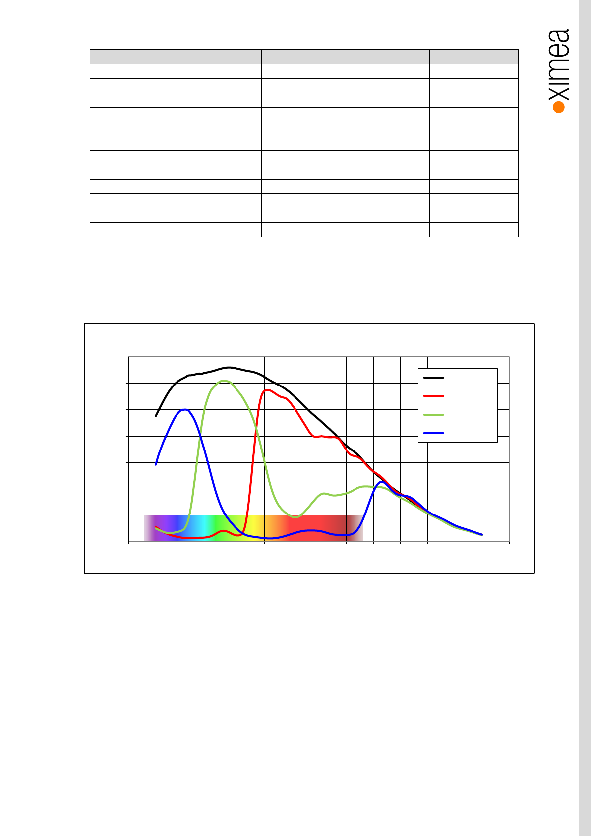
xiC - Technical Manual Version 1.16
44
Color model
Mono mode
Binning/skipping (H X V)
pixels
fps
Bit/px
Yes
Yes
1x1 / 1x1
4112 x 3008
31
8
Yes
Yes
1x1 / 1x1
4112 x 3008
24
10
Yes
Yes
1x1 / 1x1
4112 x 3008
20
12
Yes
Yes
1x1 / 1x2
4112 x 1504
62
8
Yes
Yes
1x1 / 2x1
2056 x 3008
62 8 Yes
Yes
1x1 / 2x2
2056 x 1504
124
8
No
Yes
1x2 / 1x1
4112 x 1504
62 8 No
Yes
2x2 / 1x1
2056 x 1504
124 8 No
Yes
2x2 / 1x1
2056 x 1504
99
10
No
Yes
2x2 / 1x1
2056 x 1504
83
12
Yes
Yes
1x1 / 2x2
2056 x 1504
99
10
Yes
Yes
1x1 / 2x2
2056 x 1504
83
12
0%
10%
20%
30%
40%
50%
60%
70%
350 400 450 500 550 600 650 700 750 800 850 900 950 1000 1050
Quantum Efficiency (%)
Wavelength (nm)
IMX253- Spectral Response
Monochrome
Red Bayer
Green Bayer
Blue Bayer
table 3-19, MC124xG-SY, supported standard readout modes
3.5.5.2. Quantum efficiency curves [%]
figure 3-26, IMX253 mono and color, quantum efficiency curve, ©SONY
Page 45
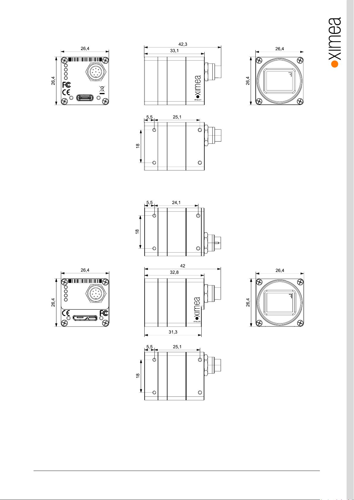
xiC - Technical Manual Version 1.16
45
4 x M2 max
. depth 2 mm
mod.
: 25.1 x 18 mm C-mount
20.1 x 18 mm CS-mount
C/CS-Mount module
A
Remove this module
for CS mount back
focal distance
C/CS-Mount module B
xiC
USB 3.1
Gen 1
USB3VISION
xiC
1
2
3
4
MC124CG-SY-TC
CUCAC1623001
Made in SK
IO
AUX
power
USB 3.1 Gen 1
Type C
4 x M2 max
. depth 2 mm
mod.
: 25.1(24.1) x 18 mm C-mount
20.1 x 18 mm CS-mount
C/CS-Mount module
A
Remove this module
for CS mount back
focal distance
C/CS-Mount module B
xiC
USB 3.1
Gen 1
USB3VISION
xiC
1
2
3
4
MC124CG-SY-UB
CUCAU1623001 Made in SK
IO
AUX
power
For use with XIMEAapproved conne ction cables only.
USB 3.1 Gen 1
3.5.5.3. Dimensional drawings MC124xG-SY-TC (C-mount [with C mount module B])
figure 3-27, dimensional drawing MC124xG-SY-TC C-Mount housing
3.5.5.4. Dimensional drawings MC124xG-SY-UB (C-mount [with C mount module B])
figure 3-28, dimensional drawing MC124xG-UB, C-Mount housing
Page 46
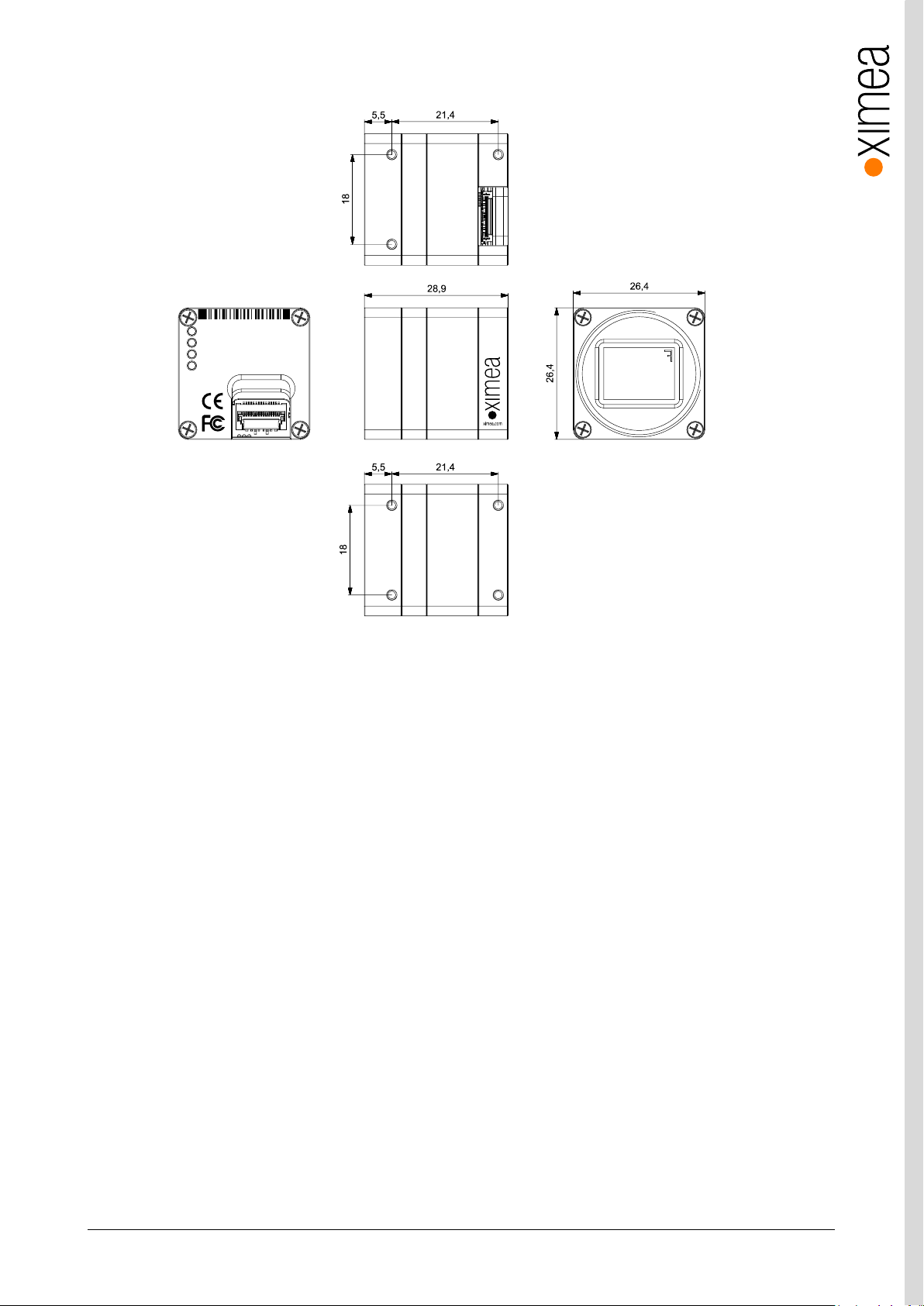
xiC - Technical Manual Version 1.16
46
xiC
1
2
3
4
MC124CG-SY-FL
CUCAF1623001
Made in SK
USB 3.1 Gen 1
xiC
USB 3.1
Gen 1
USB3VISION
4 x M2 max
. depth 2 mm
mod.
: 21.4 x 18 mm C-mount
16.4 x 18 mm CS-mount
C/CS-Mount module
A
Remove this module
for CS mount back
focal distance
C/CS-Mount module B
3.5.5.5. Dimensional drawings MC124xG-SY-FL (C-mount [with C/CS mount module B])
Figure 3-29, dimensional drawing MC124xG-FL, C-Mount housing
Page 47
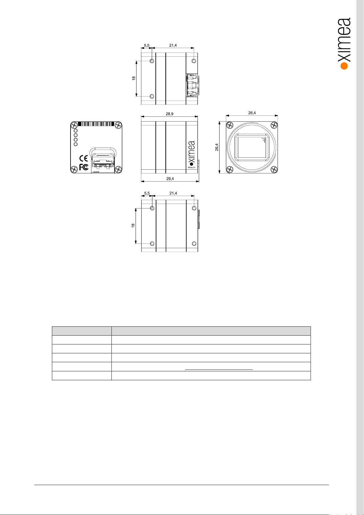
xiC - Technical Manual Version 1.16
47
feature
Note
Binning
Yes, up to 2x2 binning supported on monochrome only.
Skipping
Yes, up to 2x2
ROI
Vertical cropping results in increased read speed, horizontal reduces data transfer
HW Trigger
Trigger with overlap usable (see 4.3.2.1 Triggered acquisition - )
HDR
Not available
xiC
1
2
3
4
MC124CG-SY-FV
CUCAV1623001
Made in SK
USB 3.1 Gen 1
xiC
USB 3.1
Gen 1
USB3VISION
4 x M2 max
. depth 2 mm
mod.
: 21.4 x 18 mm C-mount
16.4 x 18 mm CS-mount
C/CS-Mount module
A
Remove this module
for CS mount back
focal distance
C/CS-Mount module B
3.5.5.6. Dimensional drawings MC124xG-SY-FV (C-mount [with C mount module B])
Figure 3-30, dimensional drawing MC124xG-FV, C-Mount housing
3.5.5.7. Referenced documents
Sony Datasheet IMX253LLR-C_TechnicalDatasheet_E_Rev0.3 (29/01/16)
Sony Datasheet IMX253LQR-C_TechnicalDatasheet_E_Rev0.1 (29/01/16)
3.5.5.8. Sensor features
table 3-20, sensor features available
Page 48
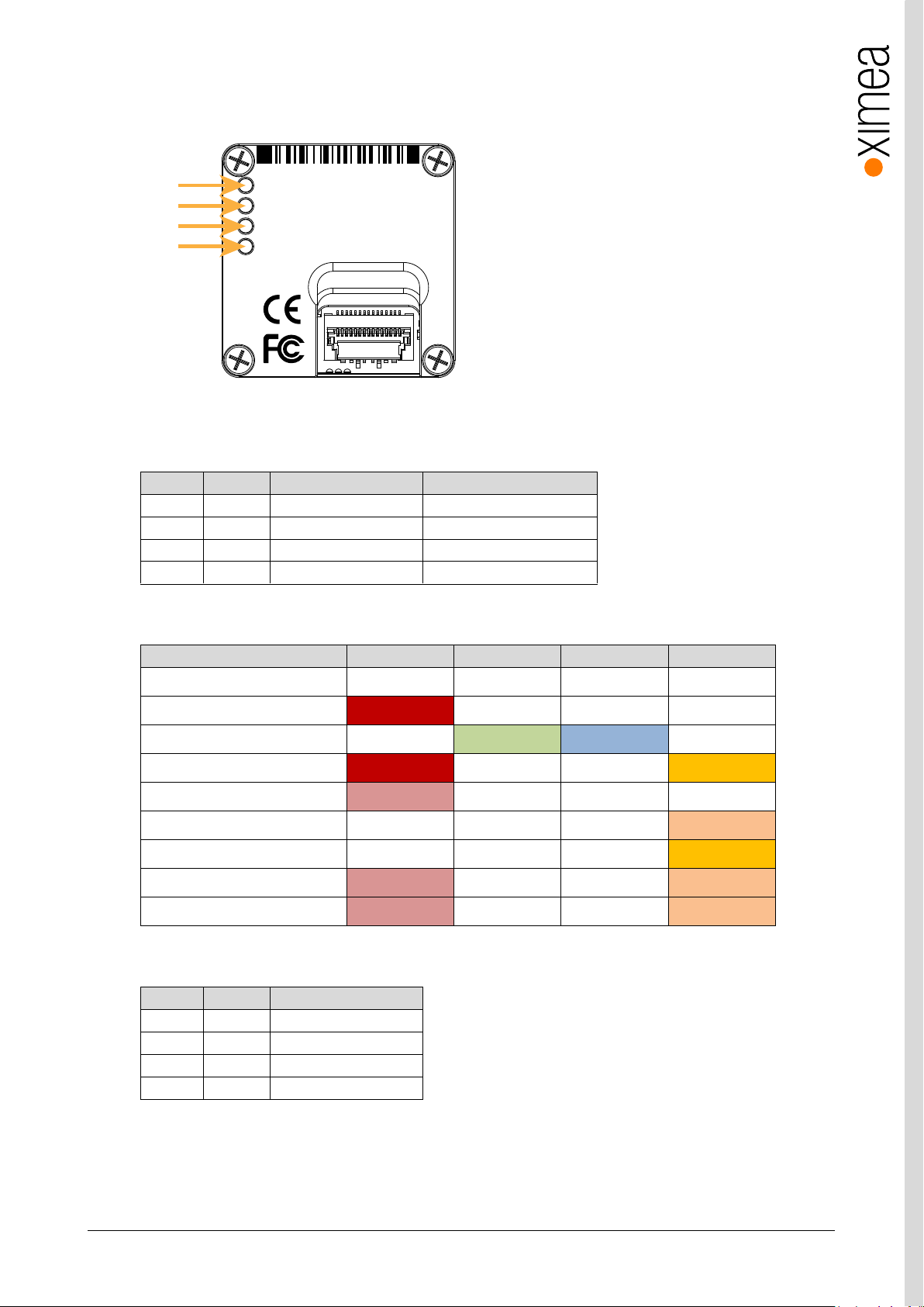
xiC - Technical Manual Version 1.16
48
LED
Color
Power-on defaults
Note 1 Red
On
User configurable
2
Green
Exposure active
User configurable
3
Blue
Frame active
User configurable
4
Orange
Connection status
User configurable
Status
LED1 (Red)
LED2 (Green)
LED3 (Blue)
LED4 (Orange)
Off
Off
Off
Off
Off
Power
On
Off
Off
Off
Booting
Off
flash ~2Hz
flash ~2Hz
Off
Boot up finished
On
Off
Off
On
USB init - wait for enumeration
flash ~1Hz
Off
Off
Off
Enumeration finished USB2
Off
Off
Off
flash ~2Hz
Enumeration finished USB3
Off
Off
Off
On
Device stop
flash ~2Hz
Off
Off
flash ~2Hz
Error
flash ~2Hz
Off
Off
flash async.
LED
Color
LED function
1
Red
On
2
Green
Exposure active
3
Blue
Frame active
4
Orange
On
xiC
1
2
3
4
MC050CG-SY-FL
CICAF1623001
Made in SK
USB 3.1 Gen 1
LED1
LED2
LED3
LED4
3.6. User interface – LEDs
Four status LEDs are located on the back of the cameras, please see below.
figure 3-31, position status LEDs
All LEDs can be configured similar as standard input and output lines.
Default LED function after power on
table 3-21, LED output description
LED statuses during boot sequence
table 3-22, LED status during boot
Default LED function after xiOpenDevice
table 3-23, LED output description
Page 49
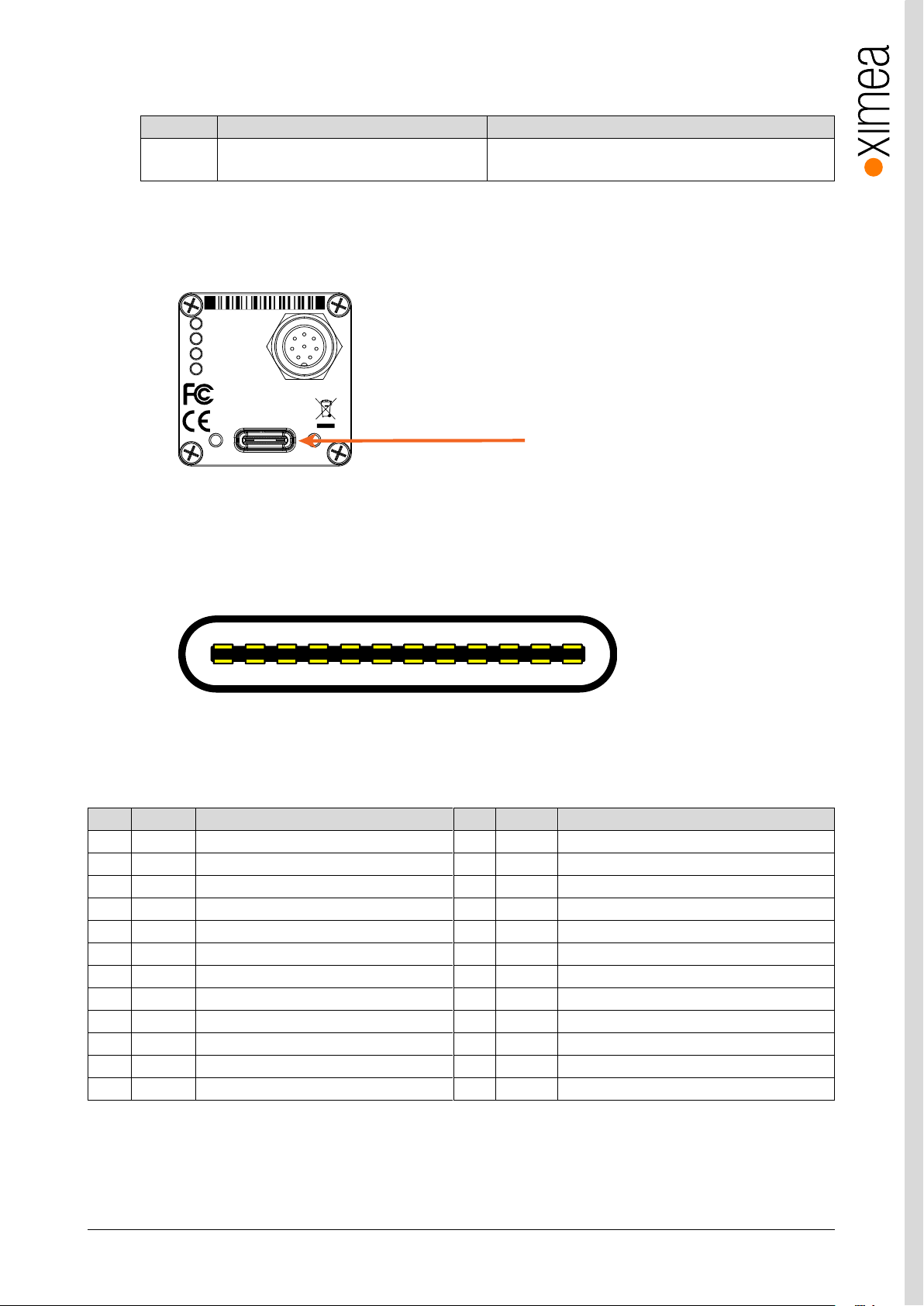
xiC - Technical Manual Version 1.16
49
Connector
Signals
Mating Connectors
USB 3.1
Standard USB 3.1 Gen1 Type-C Connector
Standard USB 3.1 Type C Connector with thumbscrews
Screw thread M2, thread distance 15.0mm
Pin
Signal
Description
Pin
Signal
Description
A1
GND
Ground return
B12
GND
Ground return
A2
SSTXp1
SuperSpeed differential pair #1, TX, pos.
B11
SSRXp1
SuperSpeed differential pair #2, RX, pos.
A3
SSTXn1
SuperSpeed differential pair #1, TX, neg.
B10
SSRXn1
SuperSpeed differential pair #2, RX, neg.
A4
VBUS
Bus power
B9
VBUS
Bus power
A5
CC1
Configuration channel
B8
SBU2
Sideband use (SBU)
A6
Dp1
Non-SuperSpeed diff. pair, position 1, pos.
B7
Dn2
Non-SuperSpeed diff. pair, position 2, neg.
A7
Dn1
Non-SuperSpeed diff. pair, position 1, neg.
B6
Dp2
Non-SuperSpeed diff. pair, position 2, pos.
A8
SBU1
Sideband use (SBU)
B5
CC2
Configuration channel
A9
VBUS
Bus power
B4
VBUS
Bus power
A10
SSRXn2
SuperSpeed differential pair #4, RX, neg.
B3
SSTXn2
SuperSpeed differential pair #3, TX, neg.
A11
SSRXp2
SuperSpeed differential pair #4, RX, pos.
B2
SSTXp2
SuperSpeed differential pair #3, TX, pos.
A12
GND
Ground return
B1
GND
Ground return
xiC
1
2
3
4
MC023CG-SY-TC
CACAC1623001
Made in SK
IO
AUX
power
USB 3.1 Gen 1
Type C
Type-C
A1 A2 A3 A4 A5 A6 A7 A8 A9 A10 A11 A12
B12 B1B2B3B4B5B6B7B8B9B10B11
3.7. xiC USB 3.1 Gen1 Type-C Interface
table 3-24, USB 3.1 mating connector description
The USB 3.1 Type C connector is used for data transmission, camera control and power.
3.7.1. Type-C connector location
figure 3-32, position of Type-C connector
3.7.2. Pinning
figure 3-33 pinning of Type-C connector
Table 3-25 USB type C connector pin assignment
Page 50
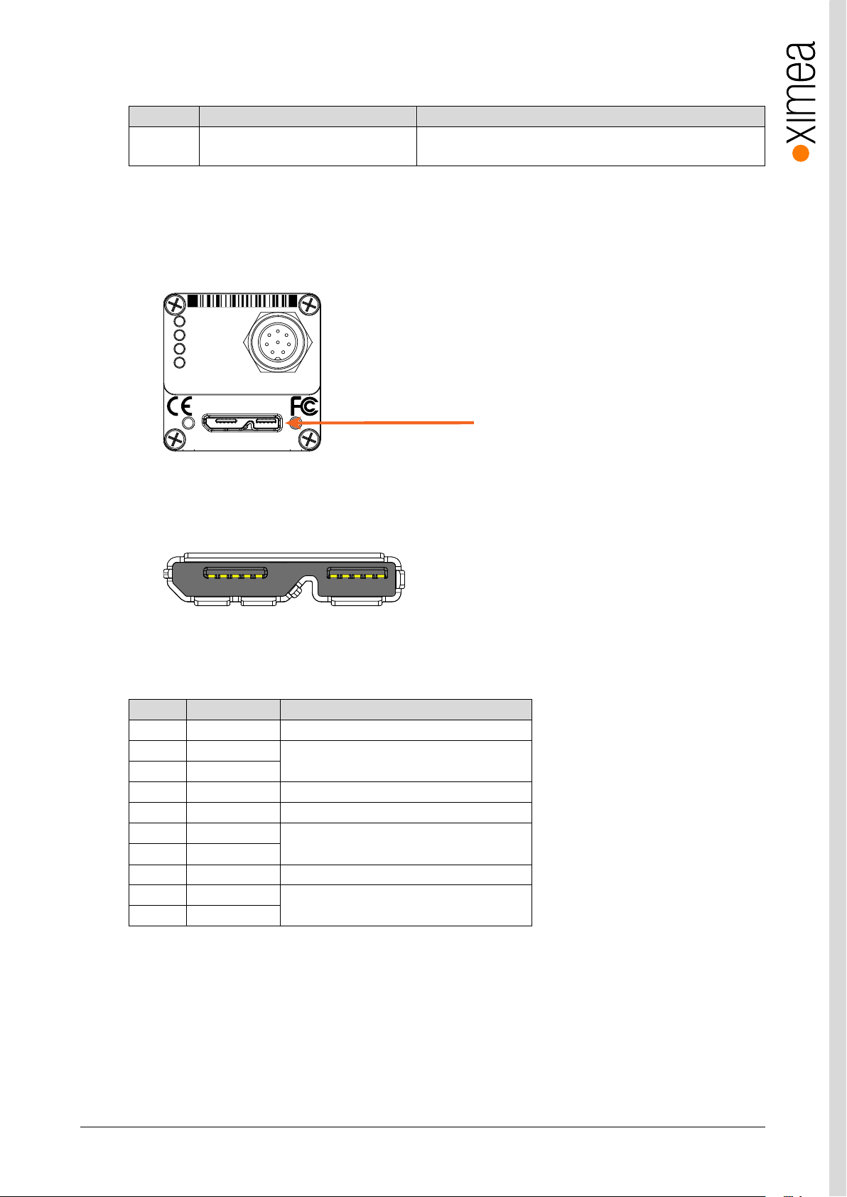
xiC - Technical Manual Version 1.16
50
Connector
Signals
Mating Connectors
USB 3.1
Standard USB 3.1 Gen 1 Micro B
Female Connector
Standard USB 3.1 Gen1 Micro-B Connector with thumbscrews
Screw thread M2, thread distance 18.0mm
Pin
Signal
Description
1
VBUS
Power
2
D-
USB 2.0 signal pair
3
D+
4
ID
OTG Identification
5
GND
Power Ground
6
SSTX-
USB 3.0 SuperSpeed transmitter signal pair
7
SSTX+
8
GND_DRAIN
USB 3.0 signal Ground
9
SSRX-
USB 3.0 SuperSpeed receiver signal pair
10
SSRX+
micro B
xiC
1
2
3
4
MC023CG-SY-UB
CACAU1623001 Made in SK
IO
AUX
power
For use with XIMEAap proved connection cables only.
USB 3.1 Gen 1
1 2 3 4 5 6 7 8 9 10
3.8. xiC USB 3.1 Gen1 micro B Interface
table 3-26, USB 3.1micro B mating connector description
The USB 3.1 Micro-B connector is used for data transmission, camera control and power.
3.8.1. USB 3.1 micro B Location
The micro B connector is located on the back side of the camera:
figure 3-34, position USB 3.1 Gen1 interface
3.8.2. Pinning
figure 3-35, pinning USB 3.1 / USB 3.0 connector
USB 3.1 Micro B connector (powered) Pin Assignment
table 3-27, USB 3.0 connector, pin assignment
The USB 3.1 / USB 3.0 standard is backward compatible with the USB 2.0 interface.
Page 51
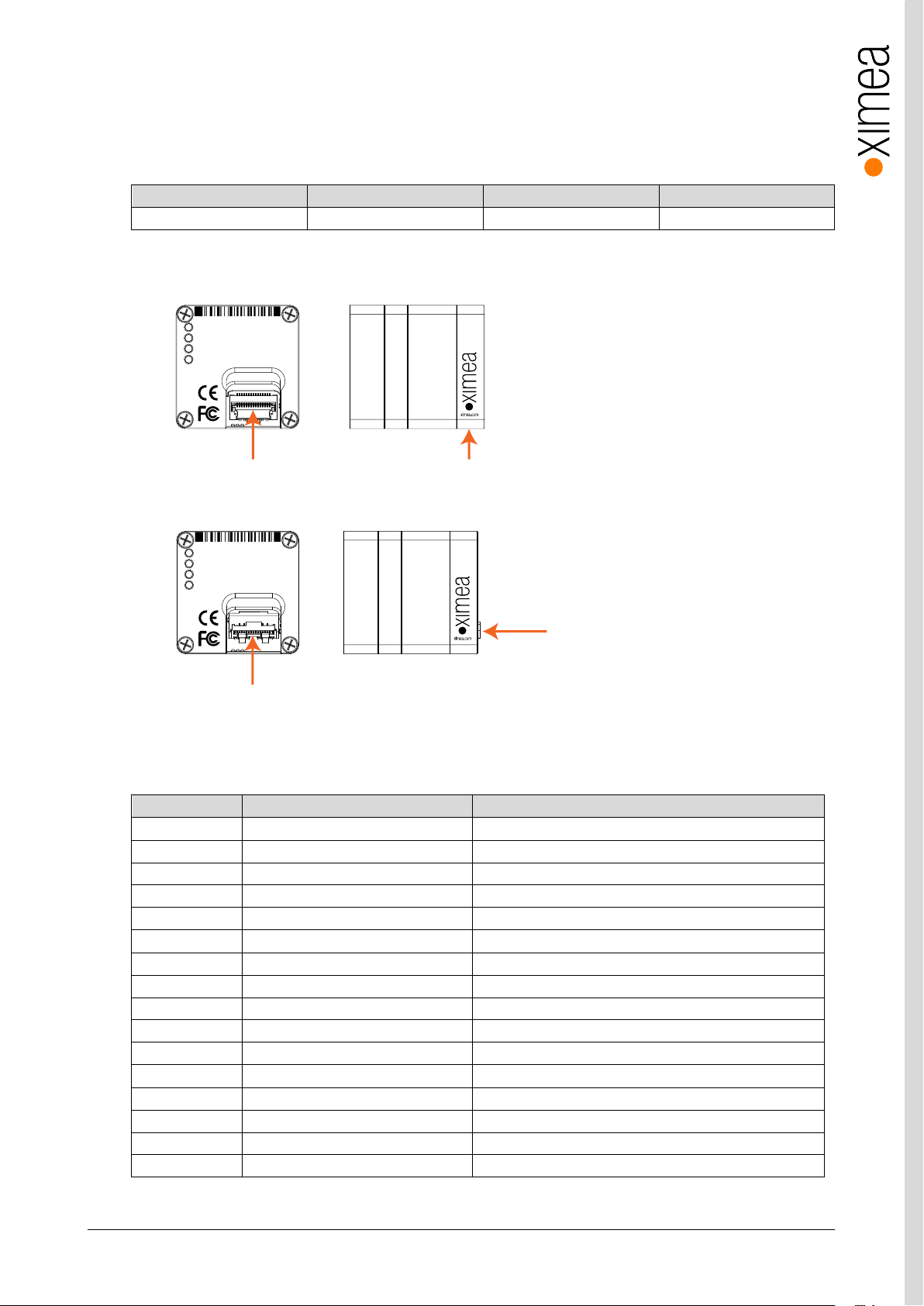
xiC - Technical Manual Version 1.16
51
Camera model
Connector
Camera model
Connector
-FL
Molex 502244-1530
-FV
Molex 502231-1500
Pin
Signal
Technical description
1
GND
Ground for power return and for SuperSpeed signal return
2
SSRX-
SuperSpeed receiver differential pair; Accepted SSRX+
3
SSRX+
SuperSpeed receiver differential pair; Accepted SSRX-
4
GND
Ground for power return and for SuperSpeed signal return
5
SSTX+
SuperSpeed transmitter differential pair; Accepted SSTX-
6
SSTX-
SuperSpeed transmitter differential pair; Accepted SSTX+
7
GND
Ground for power return and for SuperSpeed signal return
8
D+
USB 2.0 differential pair
9
D-
USB 2.0 differential pair
10
GND
Ground for power return and for SuperSpeed signal return
11
VBUS
+5V Power input
12
VBUS
+5V Power input
13
OUT1
Trigger/sync digital Output (GPO) - Open collector NPN
14
IN/OUT GND
Common pole (IO Ground
15
IN1
Trigger/sync digital Input (GPI) Current limited input
Ground pins
SGND
Shield of FPC cable connected to shield of host controller
Flex cable connector
xiC
1
2
3
4
MC023CG-SY-FL
CACAF1623001
Made in SK
USB 3.1 Gen 1
xiC
USB 3.0
Super Speed
USB3VISION
Flex cable connect direction
Flex cable connector
xiC
1
2
3
4
MC023CG-SY-FV
CACAV1623001
Made in SK
USB 3.1 Gen 1
xiC
USB 3.0
Super Speed
USB3VISION
Flex cable connect direction
3.9. xiC Flex cable interface
The flex cable interface is located on the back of the camera and comes with two different options based on the orientation the
cable plugs into the camera. The (FL) version of the camera allows the cable to approach from the bottom of the camera and
the (FV) version has the cable connecting to the camera perpendicular to the sensor surface.
Table 3-28 Connector part numbers
3.9.1. Flex Connection Location
Figure 3-36 Flex connector location FL version
Figure 3-37 Flex connector location FV version
3.9.2. Pinning
Table 3-29 Pin list for flex cable
Page 52
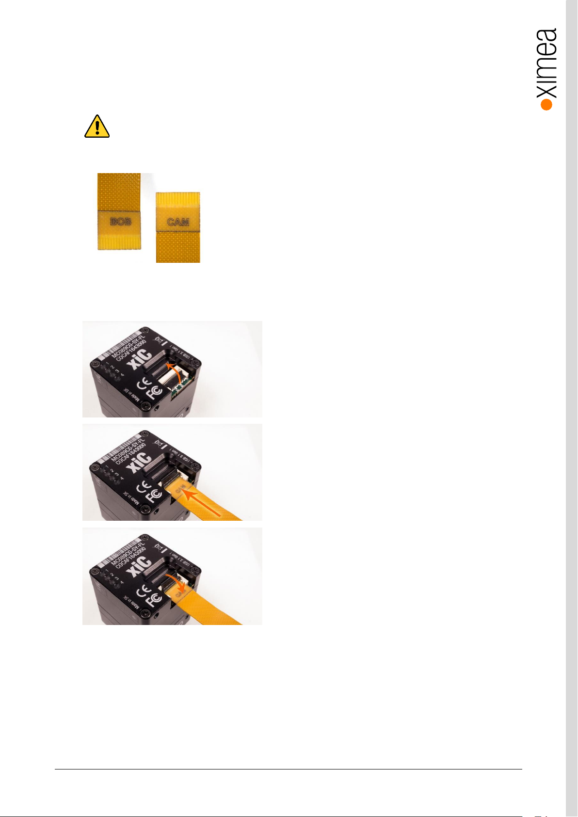
xiC - Technical Manual Version 1.16
52
3.9.3. Inserting / detaching FPC cable
When inserting or detaching cables increased caution need to be taken, to prevent connector or cable damage. MC cameras
interface connectors are equipped with locking mechanism. When locked pulling the cable may lead to damage of connector or
camera. When manipulating with cable the power supply for the camera must be turned off.
Cable have marked ends. It is important to connect the end marked “CAM” to the camera and end marked “BOB” to
host or adapter. Swapped orientation can cause damage to camera. It is important that the power is turned off when
inserting/detaching the cable.
figure 3-38, MC FPC cable laser marking
Inserting FPC cable MC option -FL
figure 3-39, MC FPC insert procedure option -FL
Open connector lock
Insert cable
Close connector lock
Page 53
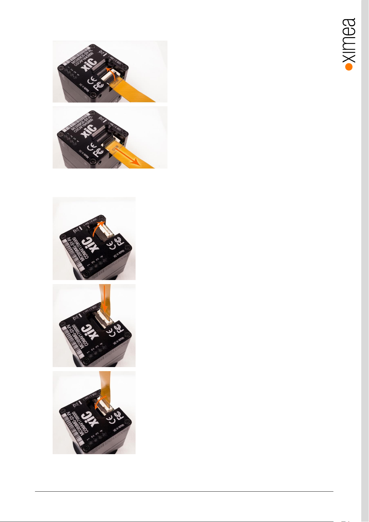
xiC - Technical Manual Version 1.16
53
Detaching FPC cable MX X2G2 option –FL
figure 3-40, MC FPC detach procedure option -FL
Inserting FPC cables MC option -FV
Open connector lock
Pull cable gently in marked direction.
Open connector lock
Insert cable
Close connector lock.
figure 3-41 MC FPC insert procedure option -FV
Page 54
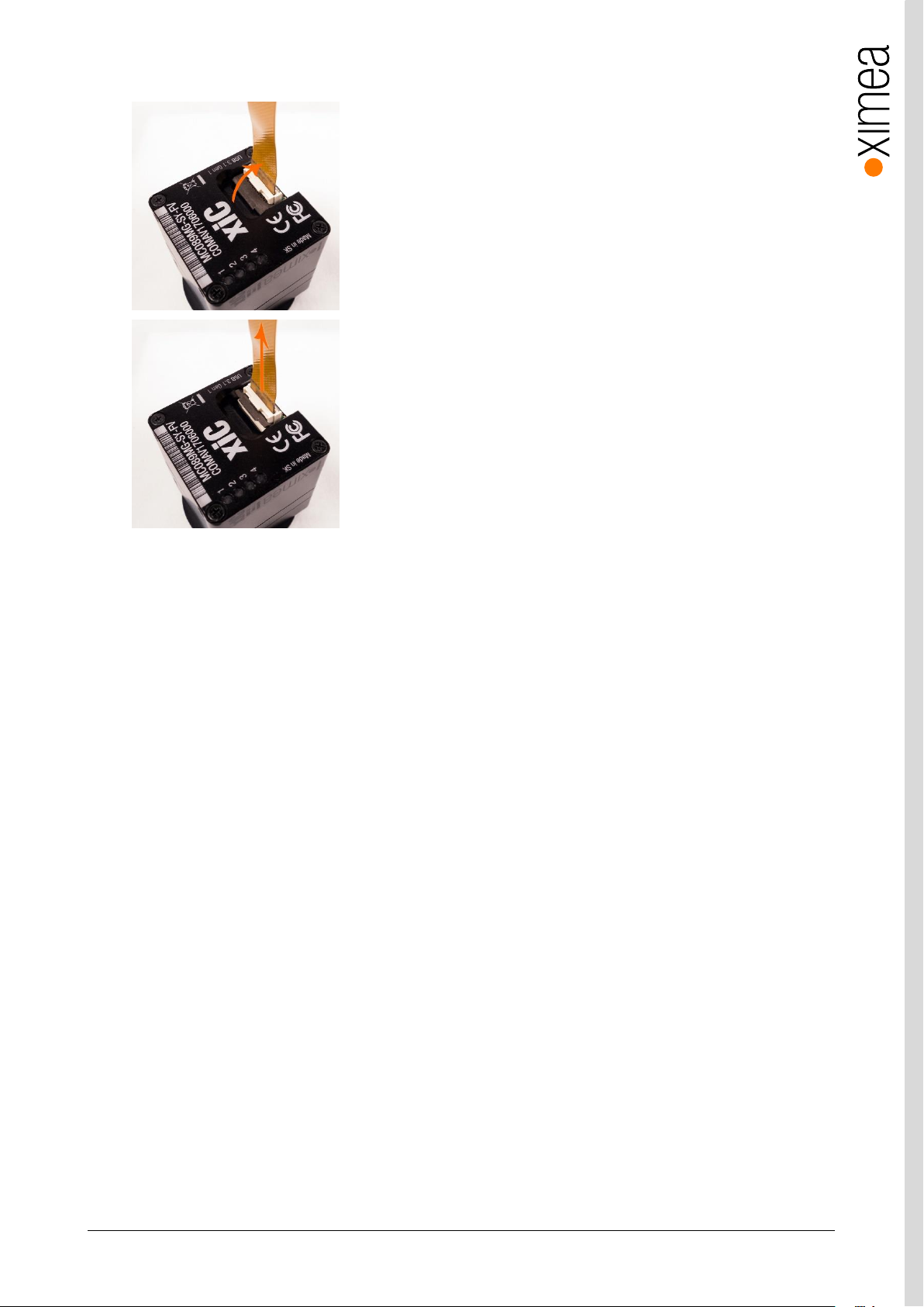
xiC - Technical Manual Version 1.16
54
Detaching FPC cable MX X2G2 option –FV
Open connector lock
Pull gently the cable out as marked.
figure 3-42, MC FPC detach procedure option -FV
Page 55
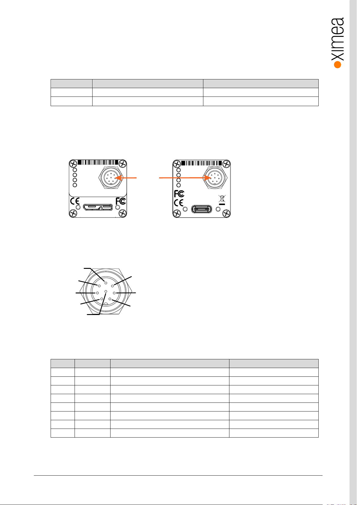
xiC - Technical Manual Version 1.16
55
Connector
Signals
Mating Connectors
I/O & Sync 8-pin
Opto-isolated trigger input and non-isolated I/O
Binder 8-pin PN: 79 1426 15 08
Flex cable
One input and one output non-isolated
Pin
Name
Signal
Technical description
1
AUX PWR
Power supply input
5V
2
INOUT2
Non-isolated I/O
LVTTL (3V, 50µA)
3
OUT1
Opto- isolated Output 1
Open collector
4
OUT GND
Ground for Opto-Isolated Out (OUT1)
5 IN1
Opto-isolated Input 1
(<0.8V low; 4-24V high)
6
IN GND
Ground for Opto-Isolated Input (IN1)
7 GND
External grounds for power and non-isolated I/O
8
INOUT1
Non-isolated I/O
LVTTL (3V, 50µA)
xiC
1
2
3
4
MC023CG-SY-UB
CACAU1623001 Made in SK
IO
AUX
power
For use with XIMEAapproved connection cables only.
USB 3.1 Gen 1
xiC
1
2
3
4
MC023CG-SY-TC
CACAC1623001
Made in SK
IO
AUX
power
USB 3.1 Gen 1
Type C
8 pin
IO/AUX
connector
1
2
3
4
5
6
7
8
3.10. xiC Digital Input / Output (GPIO) Interface
USB XiC cameras use the 8-pin connector for the GPIO interface and external power supply (AUX) connection and have multiple
options for inputs and outputs. The flex line cameras have one input and one output available through the flex line (see pin-out
above).
table 3-30, GPIO mating connector description
3.10.1. Location
IO interface receptacle (for USB cameras only) is located on the back of the camera:
figure 3-43, position GPIO connector
3.10.2. IO Connector Pinning
Pinning of the IO connector (camera):
figure 3-44, pinning GPIO connector
I/O connector Pin Assignment:
table 3-31, I/O connector Pin Assignment
Page 56
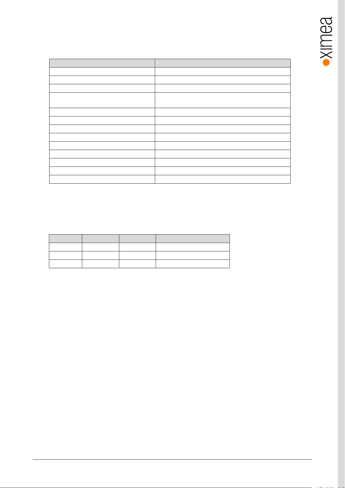
xiC - Technical Manual Version 1.16
56
Item
Parameter / note
Maximal input voltage
24V
Common pole
No
Effect of incorrect input terminal connection
Reverse voltage polarity protected
Effects when withdrawing/inserting input
module under power
No damage, no lost data
Maximum recommended cable length
5m
Input level for logical 0
Voltage < 2.0V/Current 0mA to 0.3mA
Input level for logical 1
Voltage > 4.0V/Current 4mA to 6mA
Input debounce filter
No
Input delay – rising edge
1.7 +/-0.2µs (V
INPUT
=10V, T
AMBIENT
=25°C)
Input delay – falling edge
1
10.7 +/-0.2µs (V
INPUT
=10V, T
AMBIENT
=25°C)
Number of inputs
1
External trigger mapping
Yes
Input functions
Trigger, get current level (rising or falling edge are supported)
V-in-min [V]
V-in-max [V]
State
I-max [mA]
-24.0
2.0
Off (0)
0.0 – 0.3 mA (0mA nominal)
2.0
4.0
Transient
4
4.0
24.0
On (1)
4 – 6 mA (5mA nominal)
3.10.3. Optically isolated Digital Input
3.10.3.1. Optically isolated Digital Input - General info
table 3-32, Optically isolated digital input, general info
Note: – 1) Propagation delay depends on voltage level, propagation jitter is significantly lower.
3.10.3.2. Digital Input – signal levels
Input levels are not IEC 61131-2, Type 1 as the ON state has been extended to support 5V TTL
table 3-33, digital info, signal levels
Note:
• Input level Vin represents amplitude of the input signal.
• Voltage levels referenced to common ground GND
Page 57
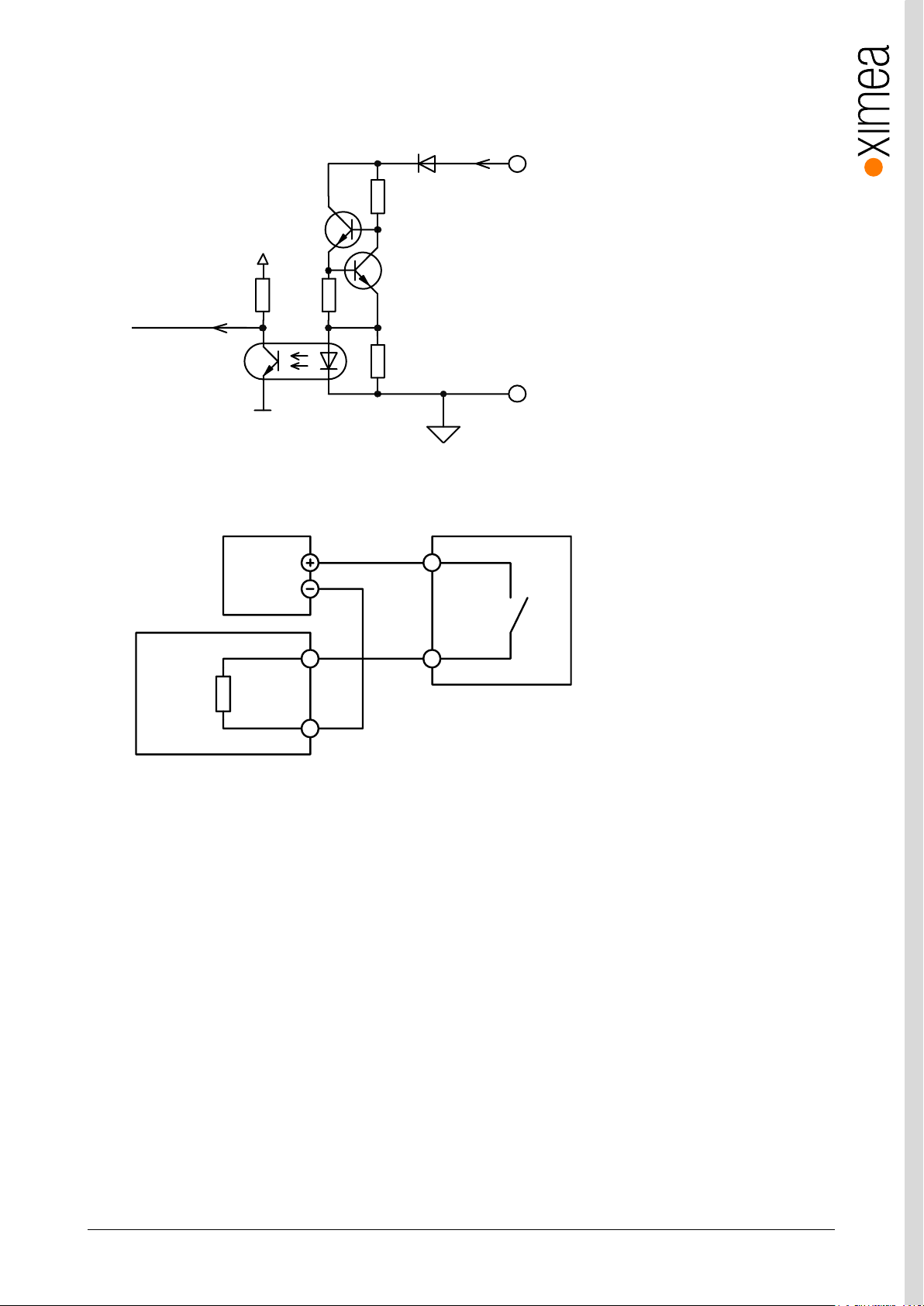
xiC - Technical Manual Version 1.16
57
VC C
D IG ITA L IN PUT
I
INPUT
FPG A _IN P UT
G ND ( Comm on I O Gr o un d)
62 0 R
10 0 R
10 K
49 K 9
GND
PLC Device
Input
Camera
GND (Common IO Ground)
Common
Output
Power Supply
3.10.3.3. Digital Input – Internal Schematic
The internal scheme of Digital Input signal flow inside the camera is below.
figure 3-45, digital input, interface schematic
3.10.3.4. Digital Input – Wiring
figure 3-46, digital input, interface wiring
Page 58
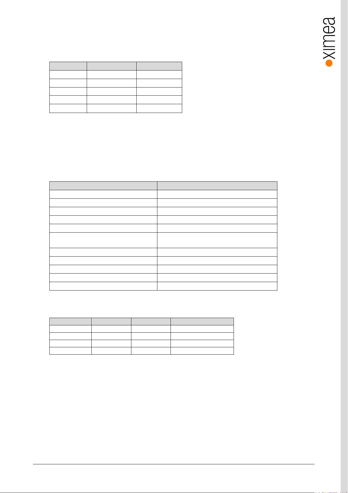
xiC - Technical Manual Version 1.16
58
Edge Type
Input Voltage [V]
Typ. delay [μs]
Rising 5 1.6
Rising
10
1.7
Falling 5 7.8
Falling
10
10.7
Falling
24
12.7
Item
Parameter / note
Maximal open circuit voltage
24V
Output port type
Open collector NPN
Protection
short-circuit / over-current / Reverse voltage
Protection circuit
PTC Resettable Fuse
Maximal sink current
25mA
Trip current
50mA – self restarting when failure mode current
disconnected
Inductive loads
No
Effect of incorrect output terminal connection
Protected against reverse voltage connection
Maximal output dropout
1.7V, sink current 25mA
Number of outputs
1
Strobe output mapping
Yes
Output current
OFF -> ON
ON -> OFF
Note
2mA
0.55 µs
41 µs
V
OUTPUT
=5V, T
AMBIENT
=25°C
5mA
0.6 µs
43 µs
V
OUTPUT
=5V, T
AMBIENT
=25°C
10mA
0.88 µs
51 µs
V
OUTPUT
=11V, T
AMBIENT
=25°C
25mA
1.4 µs
51 µs
V
OUTPUT
=13V, T
AMBIENT
=25°C
3.10.3.5. Digital Input – Timing
Typical measured input delay between Digital Input to FPGA Input
Measurements of input delays:
table 3-34, digital input, timing
Note:
• Measured at: Ambient Temperature 25°C
3.10.4. Optically isolated Digital Output
3.10.4.1. Optically isolated Digital Output - General info
table 3-35, Optically isolated digital output, general info
3.10.4.2. Optically isolated Digital Output Delay
Page 59
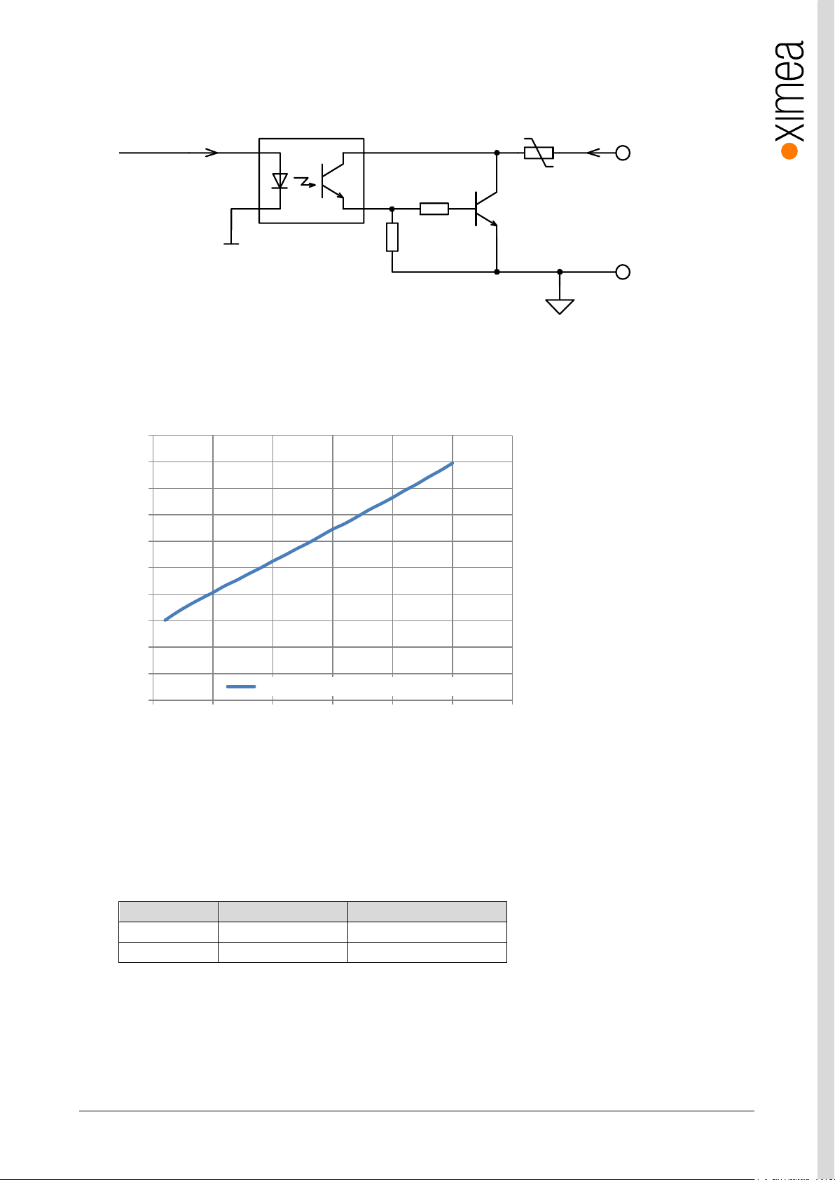
xiC - Technical Manual Version 1.16
59
Output state
Output switch state
Input state
ON
Sourcing current
Pull up (energized)
OFF
Relaxing
Not energized
PTC Fuse
FPGA_OUTPUT
GND
10K
1K
DIGITAL OUTPUT
GND (Common IO Ground)
Idrive=2mA
I
LOA D
0.0
0.2
0.4
0.6
0.8
1.0
1.2
1.4
1.6
1.8
2.0
0 5 10 15 20 25 30
V
OUTPUT
(V)
I
OUTPUT
(mA)
Output Transfer Characteristic (Receptacle)
3.10.4.3. Optically isolated Digital Output – Internal schematic
Following scheme is the internal scheme of the Digital Output signal flow inside the camera.
figure 3-47, digital output, interface schematic
Output Transfer Characteristic
When Output is in On state - typical transfer characteristic of output is as on following figure:
figure 3-48, digital output transfer characteristics
3.10.4.4. Digital Output – Wiring
Digital output has an open collector switching transistor with common IO Ground. In most cases a power source for external
device must be provided.
3.10.4.4.1. Connecting Digital OUTPUT to a NPN-compatible PLC device input (biased)
Page 60
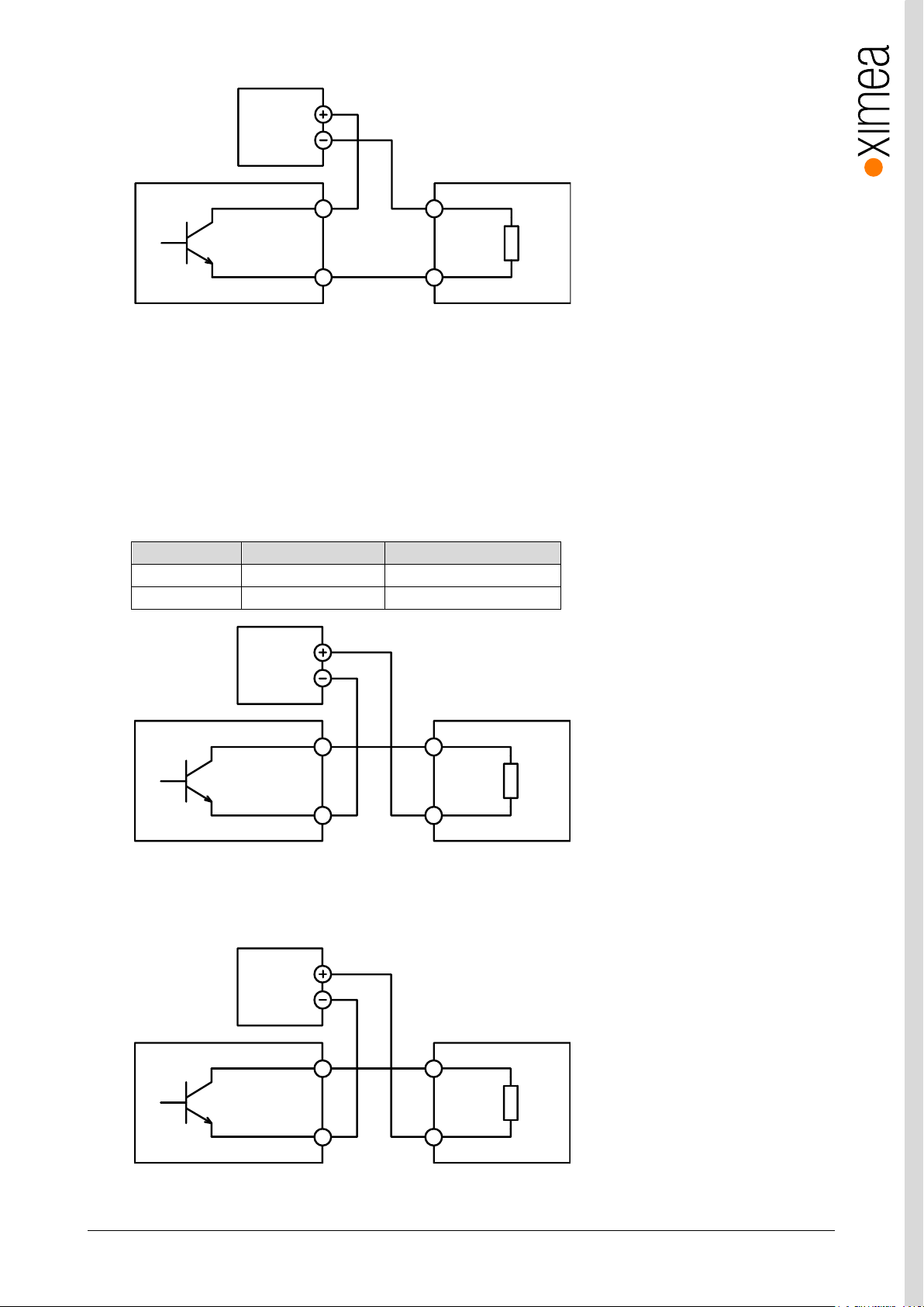
xiC - Technical Manual Version 1.16
60
Output state
Output switch state
Input state
ON
Sourcing current
Pull down (energized)
OFF
Relaxing
Not energized
GND (Common IO Ground)
DIGITAL OUTPUT Common
PLC Device
Input
Camera
Power Supply
GND (Common IO Ground)
DIGITAL OUTPUT
Common
PLC Device
Input
Camera
Power Supply
GND (Common IO Ground)
DIGITAL OUTPUT IN-
PLC Device
IN+
Camera
Power Supply
figure 3-49, Connecting Digital OUTPUT to a NPN-compatible PLC device input (biased)
Important note:
• If using this configuration, take into account that Common Ground connection may be biased by power supply for Digital
Input!
3.10.4.4.2. Connecting Digital OUTPUT to a NPN-compatible PLC device input
This type of connection is possible only when opto-isolated input is used (bidirectional in some cases) or when only one general
opto-isolated input is used.
Note:
• In this case a bidirectional opto-isolated input must be used
figure 3-50, Connecting Digital OUTPUT to a NPN-compatible PLC device input - more bidirectional inputs used
figure 3-51, Connecting Digital OUTPUT to a NPN-compatible PLC device - single input
Page 61
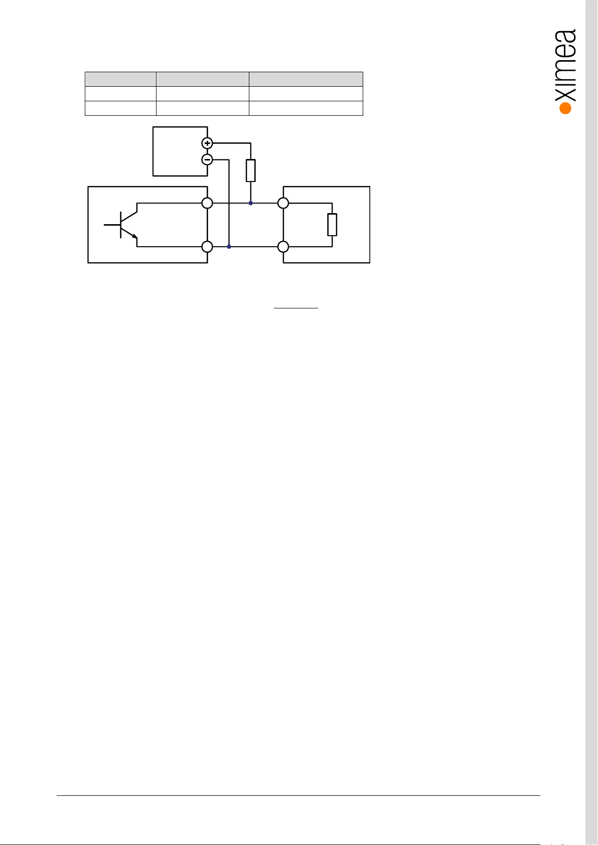
xiC - Technical Manual Version 1.16
61
Output state
Output switch state
Input state
ON
Sinking current
Not energized
OFF
Relaxing
Pull up (energized)
psu input
input
VV
R
I
psu
V
input
V
input
I
( ) ( )*
psu input input
P R V V I
GND (Common IO Ground)
DIGITAL OUTPUT
Common
PLC Device
Input
Camera
Power Supp ly
External pull up
3.10.4.4.3. Connecting Digital OUTPUT to a PNP-compatible device
figure 3-52, Connecting Digital OUTPUT to a PNP-compatible device
Pull up resistor can be calculated as follows:
Where:
power supply voltage. Must be higher than required input amplitude
required input amplitude
input driving current (corresponding to input amplitude)
Remember to use the appropriate resistor power rating
Page 62
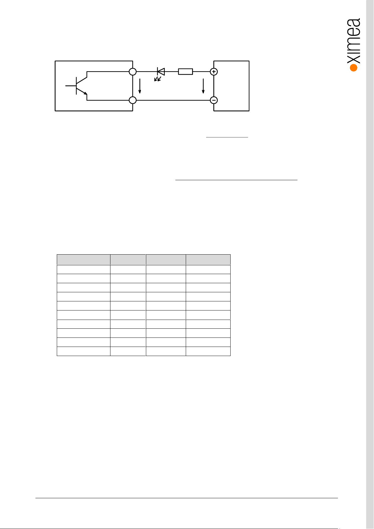
xiC - Technical Manual Version 1.16
62
psu output led
led
V V V
R
I
psu
V
output
V
led
V
led
I
LED Colour
V
led
(typ.)
V
led
(max.)
Note
Standard Red
1.7V
2.1V Super Bright Red
1.85V
2.5V
Low power Red
1.7V
2.0V Orange
2.0V
2.1V Yellow
2.1V
2.2V Green
1.9V
2.5V
Emerald Green
2.1V
2.7V Blue
2.5V
3.7V
White
2.8V
3.8V Infra-Red
1.3V
1.8V
Opto coupler
GND (Common IO Ground)
DIGITAL OUTPUT
Camera Power Supply
RLED
V
PSU
V
OUTPUT
3.10.4.4.4. Output Wiring Example: LED Driving
LED can be driven directly by camera digital output. A series resistor must be used to limit LED current.
figure 3-53, LED Driving
LED series resistor can be calculated by the following equation:
Where:
power supply voltage (5V to 24V)
voltage across digital output pins (see. 3.10.4.1 Optically isolated Digital Output - General info )
LED forward voltage (see table below)
LED current
Note:
• Remember to use the appropriate resistor power rating
Typical LED forward voltage
table 3-36, digital output, LED driving
Page 63
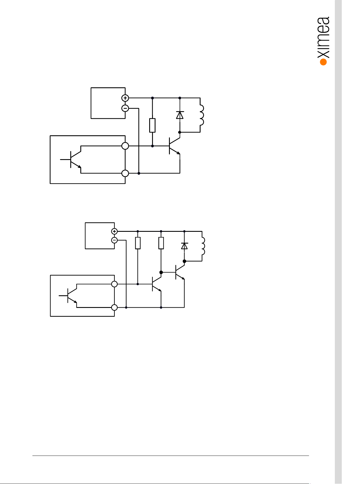
xiC - Technical Manual Version 1.16
63
GND (Common IO Ground)
DIGITAL OUTPUT
Camera
Power Supply
R
D RL
T
GND (Common IO Ground)
DIGITAL OUTPUT
Camera
Power Supply
R1
D
RL
T1
T2
R2
3.10.4.4.5. Output Wiring Example: Inductive load (Relay) Driving
Do not connect inductive load RL directly to Camera Digital Output. A transistor must be used to prevent damage of the output.
See image below for possible inductive load driving. Resistor R can be connected to Digital Outputs and power supply to provide
the necessary bias current for transistor. You should also use an external diode to protect the transistor from over voltage while
disconnecting an inductive load. Keep in mind that this connection has an inverted logic. Current will flow through the load at
the start of the camera.
figure 3-54, Inductive load (Relay) Driving (inverted logic)
For positive logic you can use a second bipolar transistor.
figure 3-55, Inductive load (Relay) Driving (non-inverted logic)
Page 64
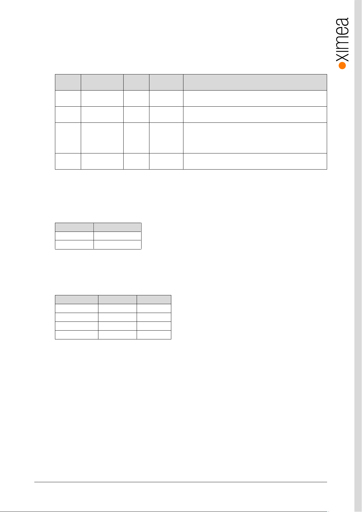
xiC - Technical Manual Version 1.16
64
Trigger
polarity
Opto-isolated
controller input
Output
delay
Wiring
Description
Positive
edge
Yes
0.5µs
figure 3-49
Negative
edge
Yes
0.5µs
figure 3-51
Positive
edge
No
155µs
figure 3-52
Not recommended in cases when short delay time is required.
Output delay is much longer than in other wiring examples. Use
external pull up in case that no pull up at controller input is
used.
Negative
edge
No
0.5µs
figure 3-52
Note that external pull up is not used in this case. Assume that
internal pull up at the controller input is used.
Edge Type
Typ. delay [μs]
Off -> On
0.5
On -> Off
155
Output current
OFF->ON
ON->OFF
2mA
0.55μs
184μs
5mA
0.55μs
182μs
10mA
0.55μs
133μs
25mA
0.55μs
113μs
3.10.4.4.6. Output Wiring Example: Driving the trigger input of a strobe controller
The digital output can be used to drive a strobe controller according to the table below.
Driving the trigger input of a strobe controller
table 3-37, digital output, wiring examples
3.10.4.5. Digital Output – Timing
Typical input delay between FPGA Output to Digital Output
table 3-38, digital output, typical timing
Note: Measured at conditions: V
Output delay depending on output current:
table 3-39, digital output, current depending timing
Note: Measured at conditions: V
OUTPUT
OUTPUT
=18V, T
=11V, T
AMBIENT
AMBIENT
=27°C
=25°C
Page 65
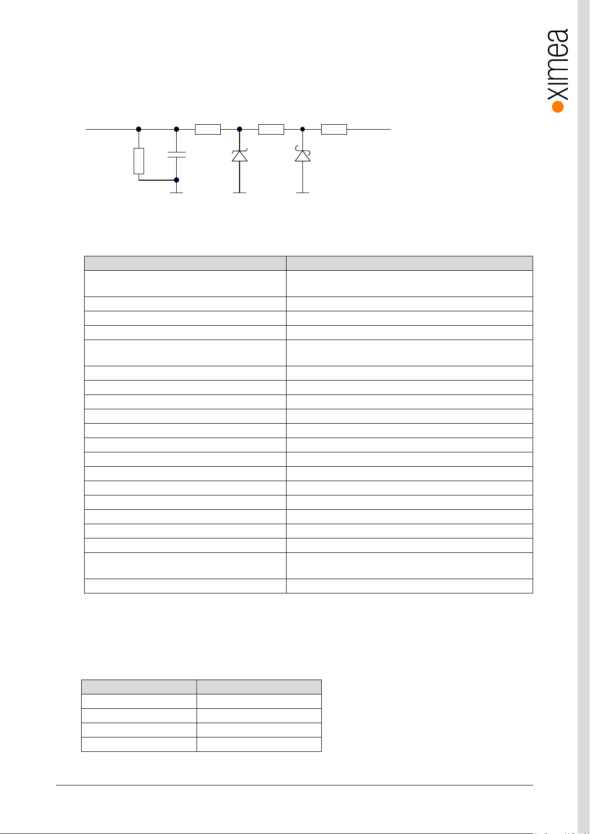
xiC - Technical Manual Version 1.16
65
Item
Parameter/note
Number of digital lines
2, each line can be configured by application separately as input or
output
Maximum input voltage
24V DC
Common pole
Yes, AUX power GND
Effect of incorrect input terminal connection
Reverse voltage polarity protected
Effects when withdrawing/inserting input module
under power
No damage, no lost data
Protection
Short-circuit/over-current/reverse voltage
Maximal output sink current
30µA, maximum advised load = 60kΩ
Inductive loads
No
Output level logical 0
<0.4V, Load 100kΩ
Output level logical 1
>2.5V, Load100kΩ
Output delay – rising edge
400ns, Load 100kΩ, threshold 2V
Output delay - falling edge
450ns, Load 100kΩ, threshold 0.5V
Input impedance – minimum
15kΩ
Input level for logical 0
<0.7V
Input level for logical 1
>3.3V
Input debounce filter
No
Input delay – rising edge
750ns, V
INPUT
=5V,T
AMBIENT
=25°C
Input delay – falling edge1
1200ns, V
INPUT
=5V,T
AMBIENT
=25°C
Input functions
Trigger, get current level; Rising or falling edge are supported for
trigger
Output functions
Off, On, Exposure active, Frame active; Signal inversion supported
Item
Parameter/note
Supported voltage range
4.5-5.5V
Typical input current*
0.65A, @5V while acquiring
Maximum input current*
0.67A, @5V
Protection
Over/under voltage protection
FPGA GPIO
100R10k1k0
10p
100k
GNDGNDGND
INOUT
3.10.5. Non-isolated Digital Lines (-UB and -TC only)
Non isolated Digital lines can be used as inputs or outputs compatible with TTL logic. These are high impedance pins so when
used as output high impedance slave input has to be used.
figure 3-56, non isolated input/output, interface schematic
3.10.5.1. Non-isolated Digital Input/Output (INOUT) General info
Table 3-40, General info for non-isolated digital in/out trigger lines.
NOTE 1) Because of low input impedance of non-isolated input it is not possible to connect master slave of two cameras
directly. Signal conditioning (buffer, opamp…) is required
3.11. External power supply input (AUX)
* Is model depended. Used values are for MC124MG-SY-TC
Page 66

xiC - Technical Manual Version 1.16
66
3.12. Heat Dissipation
XIMEA strives to offer the smallest cameras with the highest performance. Although the cameras are first in terms of power
efficiency, the high packing density of components can lead to elevated temperatures, and an adequate dissipation of this heat
must be ensured. The cameras rely on adequate surface contact with a thermal mass (tripod, lens, heat sink) of sufficient size
for heat dissipation and this must be provided ensured by the user.
Page 67
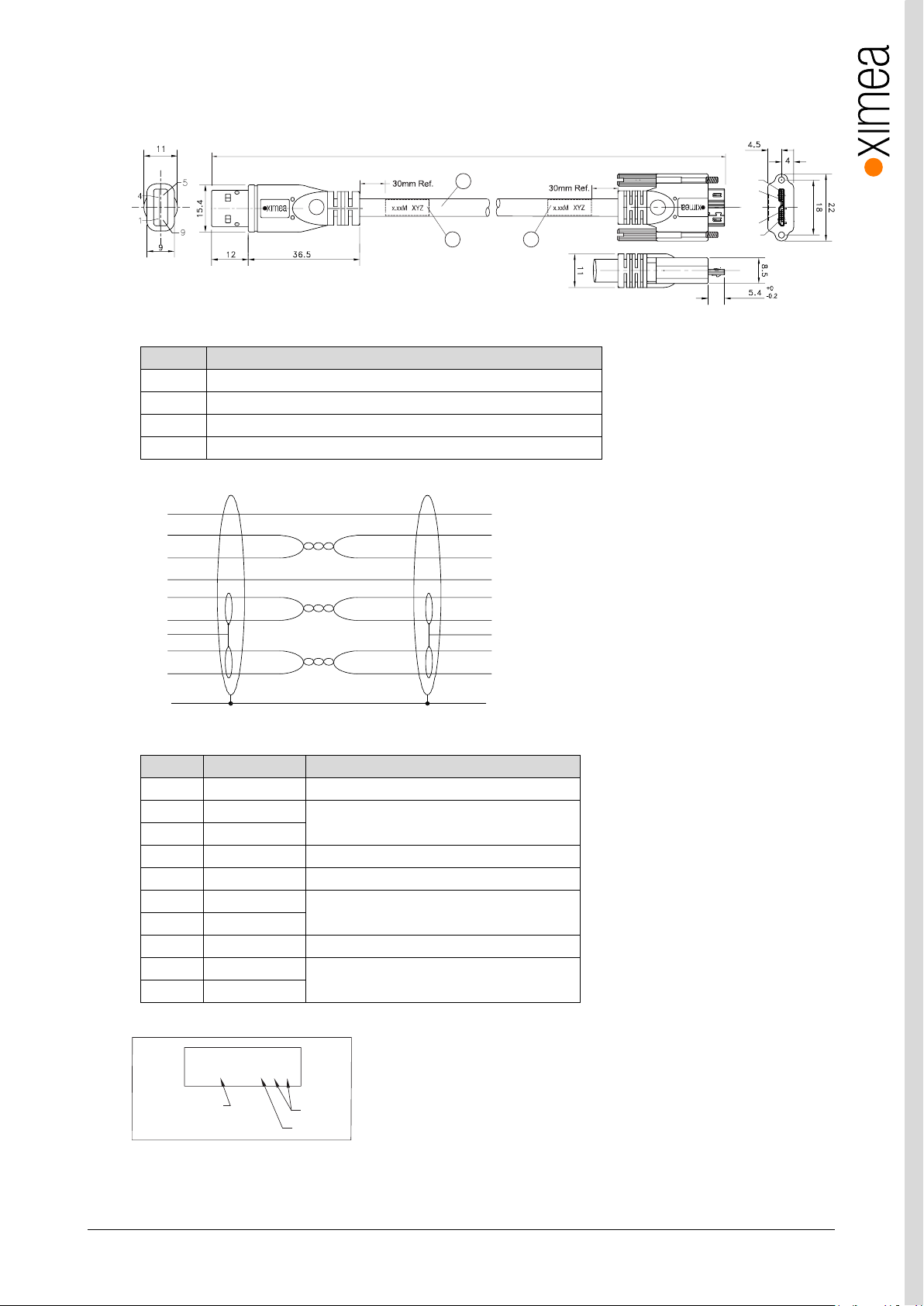
xiC - Technical Manual Version 1.16
67
Item
Description
1
USB A 3.0 9 pin Molded Plug <BLK>
2
MCD-USB-211 [OD= 7.3mm] <BLK>
3
3 USB MicB 3.0 sl 10 pin Molded Plug with Screw Locking <BLK>
4
Cable Label
Pin
Signal
Description
1
VBUS
Power
2
D-
USB 2.0 signal pair
3
D+ 4 ID
OTG Identification
5
GND
Power Ground
6
MicB_SSTX-
USB 3.0 SuperSpeed transmitter signal pair
7
MicB_SSTX+
8
GND_DRAIN
USB 3.0 signal Ground
9
MicB_SSRX-
USB 3.0 SuperSpeed receiver signal pair
10
MicB_SSRX+
1
5
6
10
2
4 4
1
3
AsperCustomerRequirements(max. 10Mrecommended)
VBUS
DD+
GND
StdA-SSRX-
StdA-SSRX+
GND-DRAIN
StdA-SSTX-
StdA-SSTX+
1
2
3
5
6
7
8
9
10
VBUS
D-
D+
GND
MicB-SSTX-
MicB-SSTX+
GND-DRAIN
MicB-SSRX-
MicB-SSRX+
Shell
Shell
Braid Shield
Braid Shield
Red
Black
White
Green
White
Green
Blue
Yellow
Blue
Yellow
Violet
Orange
Violet
Orange
1
2
3
4
5
6
7
8
9
xx .x M X Y Z
Specified
Cable Length
Week
Year
3.13. CBL-U3-1M0 / CBL-U3-3M0 / CBL-U3-5M0
1.0m / 3.0m / 5.0m USB 3.0 cables
figure 3-57, drawing USB3 cable
table 3-41, USB3 cable, components
figure 3-58, wiring USB3 cable
table 3-42, USB3 connector, pin assignment
figure 3-59, label details USB3 cable
Page 68
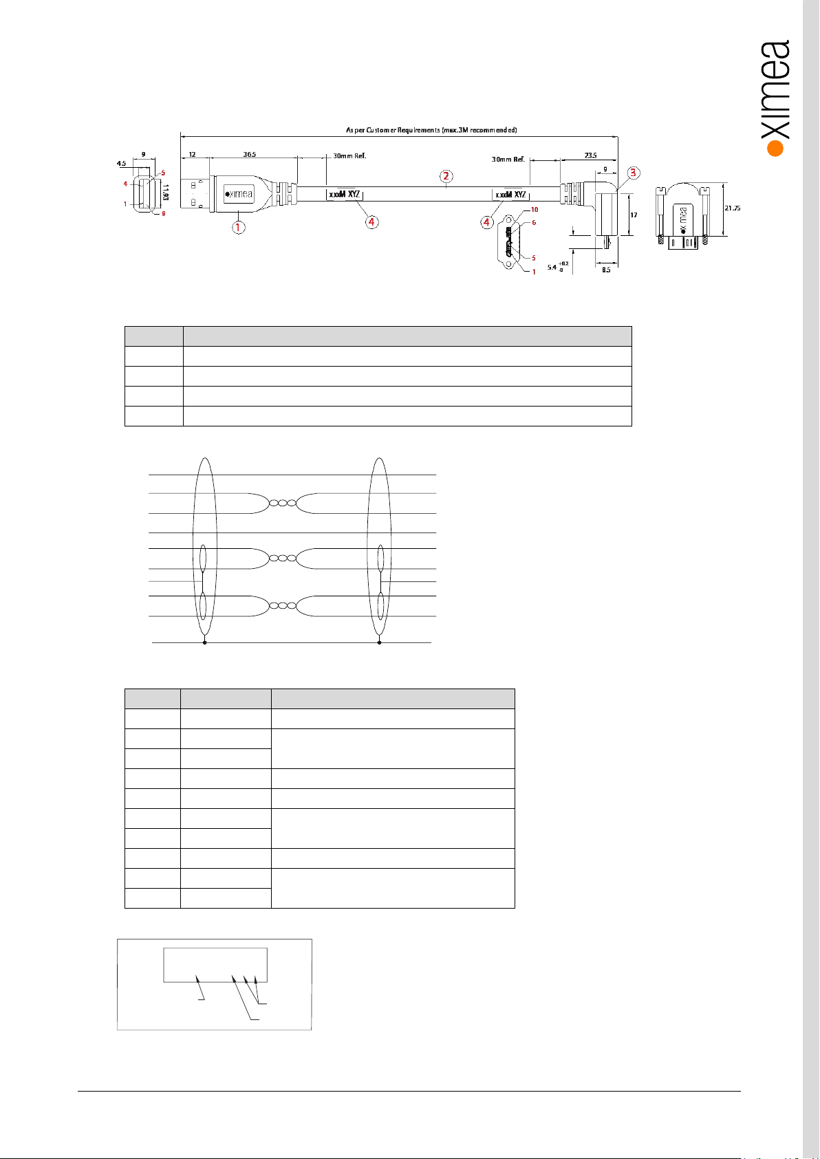
xiC - Technical Manual Version 1.16
68
Item
Description
1
USB A 3.0 9 pin Molded Plug <BLK>
2
A12-7143 [OD=5.9mm] <BLK> UL20726 2STP#30 + 1UTP#28 + 2C#26
3
USB MicB 3.0 sl 90D A1(10 pin Molded Plug) <BLK>
4
Cable Label
Pin
Signal
Description
1
VBUS
Power
2
D-
USB 2.0 signal pair
3
D+
4
ID
OTG Identification
5
GND
Power Ground
6
MicB_SSTX-
USB 3.0 SuperSpeed transmitter signal pair
7
MicB_SSTX+
8
GND_DRAIN
USB 3.0 signal Ground
9
MicB_SSRX-
USB 3.0 SuperSpeed receiver signal pair
10
MicB_SSRX+
VBUS
DD+
GND
StdA-SSRX-
StdA-SSRX+
GND-DRAIN
StdA-SSTX-
StdA-SSTX+
1
2
3
5
6
7
8
9
10
VBUS
D-
D+
GND
MicB-SSTX-
MicB-SSTX+
GND-DRAIN
MicB-SSRX-
MicB-SSRX+
Shell
Shell
Braid Shield
Braid Shield
Red
Black
White
Green
White
Green
Blue
Yellow
Blue
Yellow
Violet
Orange
Violet
Orange
1
2
3
4
5
6
7
8
9
xx .x M X Y Z
Specified
Cable Length
Week
Year
3.14. CBL-U3-3M0-ANG
3.0m USB 3.0 cable, angled micro USB3 connector
figure 3-60, drawing USB3 cable angled
table 3-43, USB3 cable angled, components
figure 3-61, wiring USB3 cable angled
table 3-44, USB3 connector, pin assignment
figure 3-62, label details USB3 cable angled
Page 69
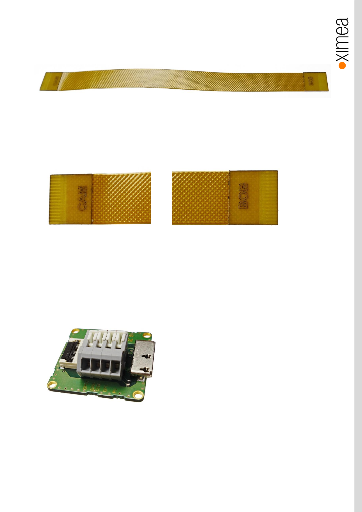
xiC - Technical Manual Version 1.16
69
3.15. CBL-MQ-FL-0M1
Cable FPC MQ Flex-Line, 0.1m can be used for connecting xiC flex line models to carrier board or trough adapter and standard
USB 3.0 cable to the host computer.
figure 3-63, flex cable
It is necessary to observe cable orientation as the wiring is nor symmetrical. The cables end are marked with:
“CAM” – camera side of the cable
“BOB” – host side of the cable
figure 3-64, flex cable ends
3.16. BOB-MQ-FL
Break Out Board, Simple Board Level. Enables access to the optoisolated input and output. FPC cable connector pinout is
exactly mirrored from camera pinout. Please refer to 3.9.2 Pinning
figure 3-65, drawing USB3 cable
Page 70
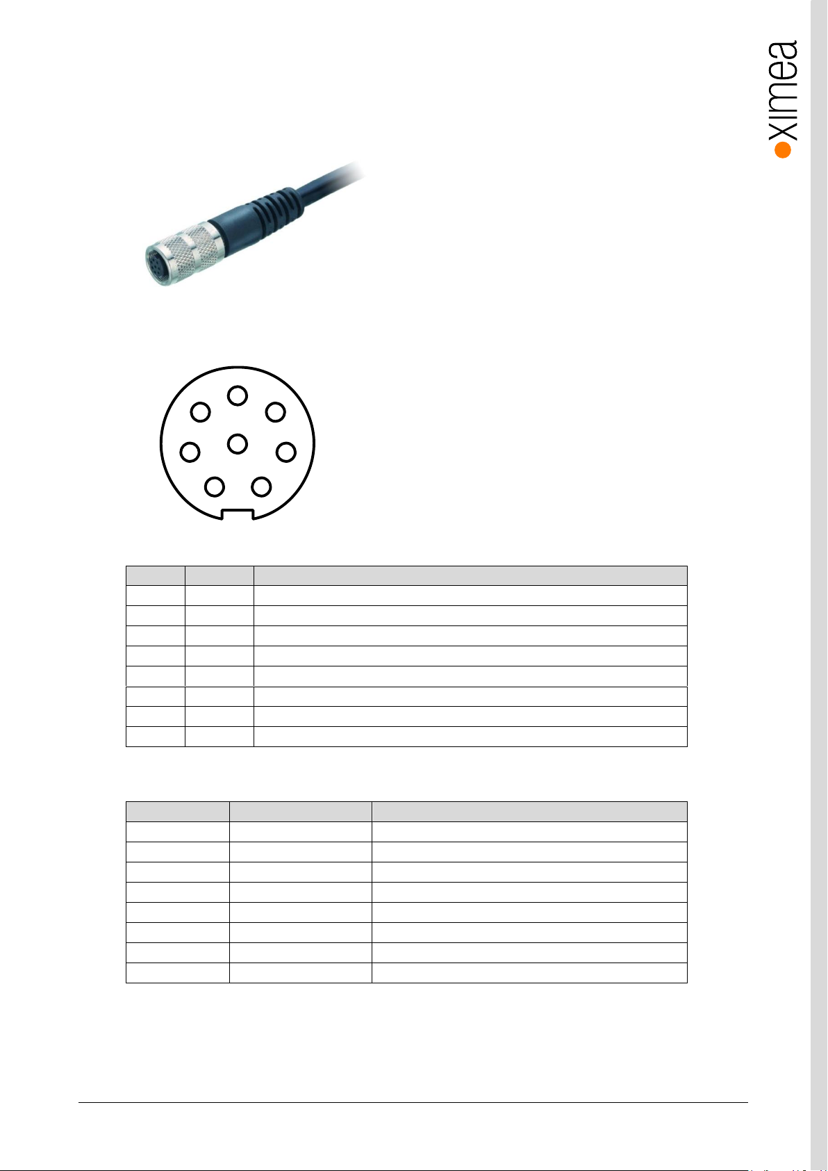
xiC - Technical Manual Version 1.16
70
Pin
color
Signal 1 White
AUX power supply input
2
Brown
INOUT2 - non-isolated Input/Output
3
Green
OUT1 - Opto-isolated Output
4
Yellow
OUT_GND Opto-Isolated output ground pole
5
Grey
IN1 - Opto-isolated Input
6
Pink
IN_GND Opto-Isolated input ground pole
7
Blue
External grounds for power supply and non-isolated I/O
8
Red
INOUT1 - non-isolated Input/Output
Part number
Manufacturer
Link
79 1426 12 08
binder
https://www.binder-usa.com/products/partsdetail/88888
79 1426 15 08
binder
https://www.binder-usa.com/products/partsdetail/88890
79 1426 72 08
binder
https://www.binder-usa.com/products/partsdetail/88889
79 1426 75 08
binder
https://www.binder-usa.com/products/partsdetail/88892
79 1462 212 08
binder
https://www.binder-usa.com/products/partsdetail/88901
79 1462 215 08
binder
https://www.binder-usa.com/products/partsdetail/88904
79 1462 275 08
binder
https://www.binder-usa.com/products/partsdetail/88905
79 1462 272 08
binder
https://www.binder-usa.com/products/partsdetail/88906
1 7
8
6
5
4
3
2
3.17. CBL-702-8P-SYNC-5M0
5.0m xiC / xiT series I/O Sync cable 8 poles
Sync cable wiring
figure 3-66, IO/AUX cable pin numbering
table 3-45, IO/AUX cable, pin assignment
3rd party cables compatible with xiC
table 3-46, alternative cables,
Page 71
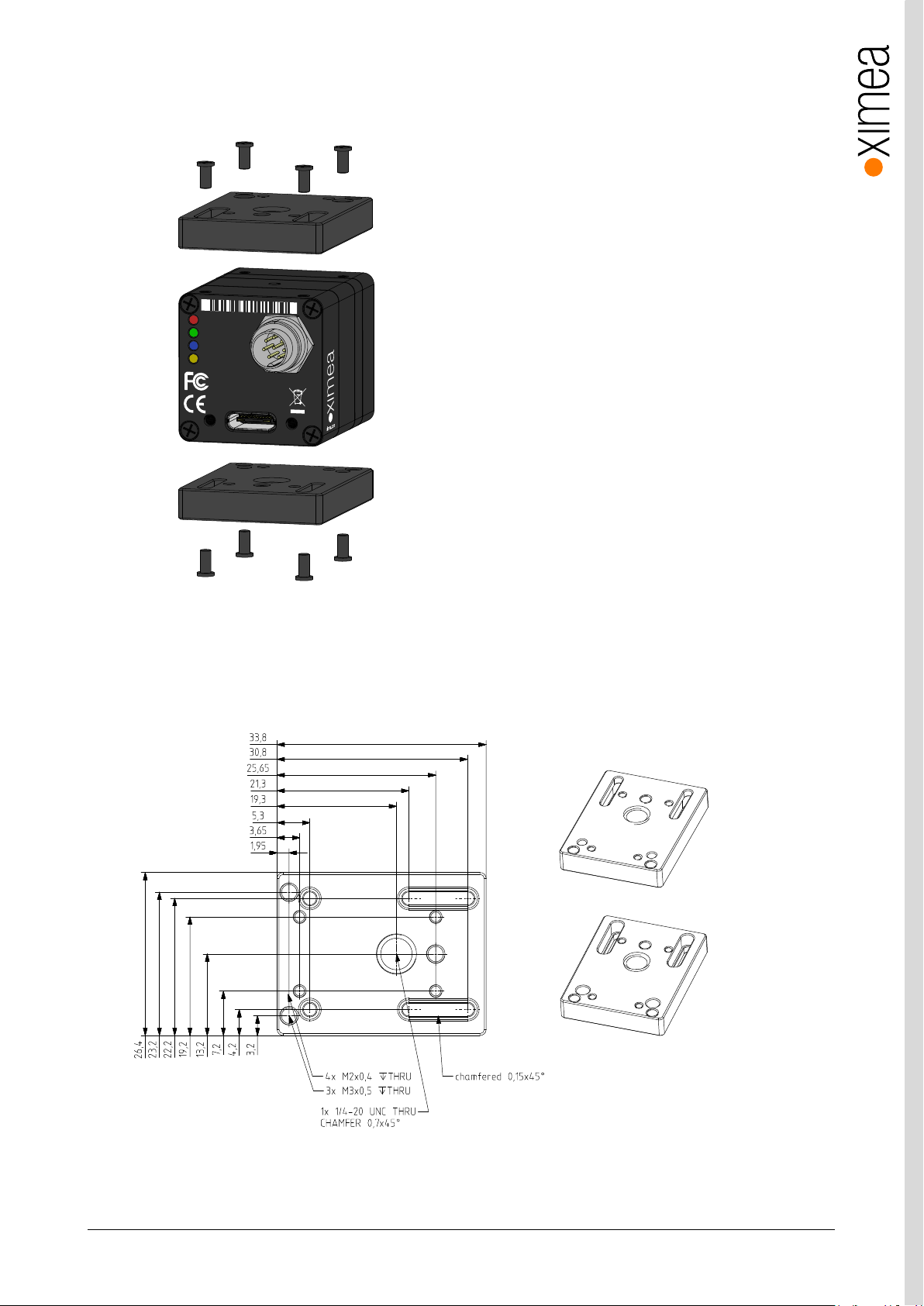
xiC - Technical Manual Version 1.16
71
xiC
1
2
3
4
MC050CG-S
Y
-TC
CICAC1623001
Made in SK
IO
AUX
p
o
wer
USB 3.1 Gen 1
T
ype C
xiC
USB 3.1
Gen1
USB3VISION
3.18. Tripod Adapter – MECH-MC-BRACKET-KIT
xiC series tripod mounting bracket
figure 3-67, mounting tripod adapter
xiC series tripod mounting bracket with 1/4-20 thread.
Use 4x SROB-M2x4-CUST screws (included) for mounting. Bracket can be mounted on the bottom or top side of the camera.
3.18.1. Dimensional drawings
figure 3-68, dimensional drawing tripod adapter
Mass without screws: 11.4 g.
Page 72
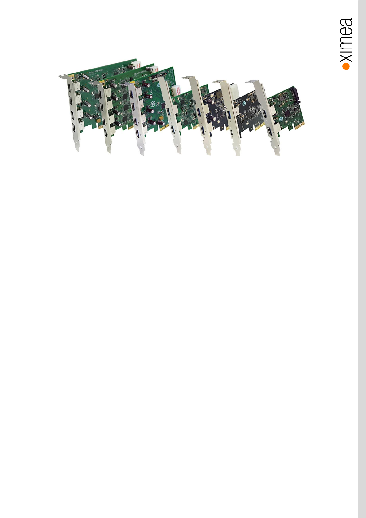
xiC - Technical Manual Version 1.16
72
3.19. USB 3 host adapters
USB 3.0 to PCI Express x1 Gen2 Host Card
figure 3-69, USB3 host adapters
Please refer to following page https://www.ximea.com/support/projects/usb3/wiki/USB_3_Host_Adapters for more
information.
System requirements
All requirements depend on selected host adapter. Please refer to host adapter specification
Page 73

xiC - Technical Manual Version 1.16
73
4. Operation
For a proper operation of your xiC camera there are certain requirements that have to be met. You can read more about these
requirement as well as about the correct usage of xiC camera in the following sections.
4.1. System Requirements
4.1.1. Software Requirements
The xiC cameras are compatible with the following operating systems:
• Windows 10
• Windows 7 SP1
• Linux Ubuntu
• MacOS 10.8 or newer
All XIMEA cameras are compatible with the most advanced Vision and Image Processing Libraries.
See chapter 5 Software for more information about the options to access a xiC cameras, as well as a list of currently
supported libraries and frameworks supported in Windows.
For more information visit page: https://www.ximea.com/support/wiki/apis/APIs
4.1.2. Hardware Requirements
The XIMEA xiC cameras are compatible with USB 3.1, USB 3.0 and USB 2.0. Please note, that the highest performance can only
be achieved by using high performance USB 3.1 or USB 3.0 ports. Using a USB 2.0 port will lead to a limited frame rate.
Please note details and the most recent info at:
Recommended hardware http://www.ximea.com/support/wiki/usb3/Compatible_hardware
4.1.2.1. System Configuration
Minimum system configuration:
For a basic operation of your xiC camera with a PC the following minimum system configuration is required. Please note that
bandwidth and processing performance are tied to the hardware configuration and the minimum hardware configuration could
lead to a reduced bandwidth and limited frame rate.
CPU: Intel i3 or better
RAM: 2GB RAM or more
Disc Space: 200 MB of free disc space
Video: NVIDIA or Radeon graphics card 128MB or integrated on CPU
Ports: Motherboard with USB 2.0 or USB 3.0 port or PCIe x1-16 Gen 2 slot for compatible USB 3.0 host
adapter
Page 74

xiC - Technical Manual Version 1.16
74
Recommended system configuration:
For best processing performance and bandwidth we recommend to use the following system configuration. This is essential
when using the higher resolution models for achieving maximum frame rate.
CPU: Intel i7
RAM: 4GB RAM or more
Disc Space: 200 MB of free disc space
Video: NVIDIA or Radeon graphics card 128MB or integrated on CPU
Ports: Motherboard with a USB 3.1 Gen1 port connected to a high performance chipset (e.g. Intel QM77, Z77
or successors) and/or PCIe x1-16 Gen 2 slot for compatible USB 3.1 Gen1 host adapter. Some host
adapters may require PCIe Gen3 ports (see next chapter for more details).
4.1.2.2. USB 3.1 Host Adapter
For a stable operation of your xiC camera and achieving the maximum possible system performance with the highest frame rate
it is important to choose an appropriate USB 3.1 host adapter chipset.
Please have a look at the following link to our webpage: http://www.ximea.com/support/wiki/usb3/Compatible_hardware
XIMEA maintains a regularly updated overview of compatible USB 3.0 and USB 3.1 host adapters together with the available
bandwidth https://www.ximea.com/support/projects/usb3/wiki/USB_3_Host_Adapters
The maximum data transfer rate depends on different conditions (motherboard, chipset, driver version, operating system,...).
PCI Express (PCIe) bus speed requirement: To achieve maximum performance of USB3 cameras - USB 3.1 host adapter must
be connected to the PCIe slot/port/hub and running at 5GT/s in case of PCIe Gen2 host adapters. For cards requiring Gen3 the
speed needs to be 8GT/s.
4.1.2.3. Cables
The USB 3.1 Gen1 cable that you use with the xiC camera is responsible for the power supply and the data transfer to the PC. It
is required to use an industrial USB 3.1 Gen1 cable with a proper wiring and shielding. We recommend using XIMEA industrial
USB 3.1 Gen1 cables in order to achieve the maximum possible performance of the camera.
XIMEA offers several passive USB 3.1 Gen1 cables and a sync cables, please see 3.13 CBL-U3-1M0 / CBL-U3-3M0 / CBL-U3-
5M0, 3.14 CBL-U3-3M0-ANG and 3.15 CBL-MQ-FL-0M
Page 75

xiC - Technical Manual Version 1.16
75
4.2. Video Formats
4.2.1. Full Resolution
By default, each camera outputs a full resolution image based on its sensor specification.
4.2.2. ROIs – Region Of Interest
ROI, also called area-of-interest (AOI) or windowing, allows the user to specify a sub-area of the original sensor size for readout.
Depending on the sensor xiC cameras support the definition of one single ROI by specifying the size (width and height) as well
as the position (based on upper left corner) of the of the sub-area.
Please note 3.5 Model Specific Characteristics
4.2.3. Downsampling Modes
Downsampling describes the possibility of reducing the image resolution without affecting the sensors physical size, ie. without
reducing the physical size of the sensing area. This feature is useful when optics are used, that are particularly fitted to a certain
sensor size and if it is necessary to maintain the full image circle on the sensor.
Downsampling can be achieved in two ways: binning and skipping.
4.2.3.1. Binning
When binning is applied, the image is divided into cluster of k*l pixels, where all pixels in each cluster are interpolated and result
in the value of one output pixel. For example, a 2*2 binning produces 2*2 pixel clusters and results in images with ¼ of the
original resolution.
4.2.3.2. Skipping
When skipping is chosen, only every n-th pixel is used to create the output image. For example, with a 2x1 vertical skipping,
every odd number line used and every even number line is skipped, resulting in an image with half its original vertical resolution.
Skipping is a faster downsampling mode, but also introduces more aliasing effects.
Page 76
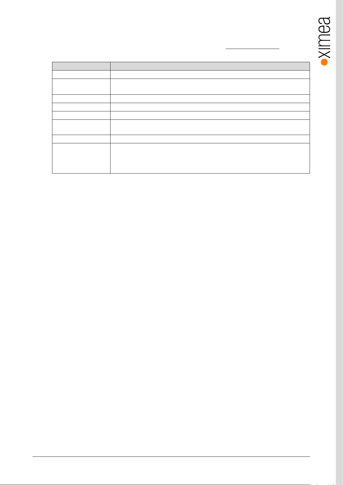
xiC - Technical Manual Version 1.16
76
Mode
Description
RAW8
Raw sensor data, 8 Bit per pixel, single channel
RAW16
Raw sensor data, 16 Bit per pixel, single channel
10 or 12 Bit sensor output (LSB) with bit-shift up to 16 Bit
MONO8
Intensity output, 8 Bit per pixel, single channel
MONO16
Intensity output, 16 Bit per pixel, single channel
RGB24
RGB filtered output, 24 Bit per pixel, 3 channels Sequence: [Blue][Green][Red]
RGB32
RGBA filtered output, 32 Bit per pixel, 4 channels, Alpha channel equals 0. Sequence:
[Blue][Green][Red][0]
RGB_PLANAR
RGB filtered output with planar-oriented channels. Format: [R][R]...[G][G]...[B][B]...
FRM_TRANSPORT_DATA
Data from transport layer (e.g. packed). This format is optimal when an efficient storage and
later (offline) processing is required.
Format is defined by XI_PRM_TRANSPORT_PIXEL_FORMAT
4.2.4. Image Data Output Formats
All modes are provided by the xiAPI or standard interfaces using the xiAPI (please note 5.1 Accessing the Camera).
Each xiC cameras supports several Image Data Output Formats.
table 4-1, image formats,
Note1: For color modes RGB32 and RGB24 the image from sensor needs to be pre-processed (de-bayering). CPU load is higher
in these modes. Setting this parameter will reset current region of interest. RGB24 is being processed from the RGB32 by
removing the unused Alpha channel creating a slightly higher CPU load than the RGB32 format.
Note2: The color filtering (de-bayering) relies on the interpolation of adjacent pixels in order to create pixel in the target image.
Pixels on the edges of the image are missing adjacent pixels and therefore cannot be used for the interpolation process. The
result is a target image that is smaller than the source image (4 pixels on all sides).
Note3: For most formats the transport data can be packed. 12-bit pixel bit depth transfers only 12bit per pixel compared to
16bit per pixel when the data are not packed. In case of packed format the CPU load is higher due to unpacking of the image
data. Available bandwidth is however used optimally.
Page 77
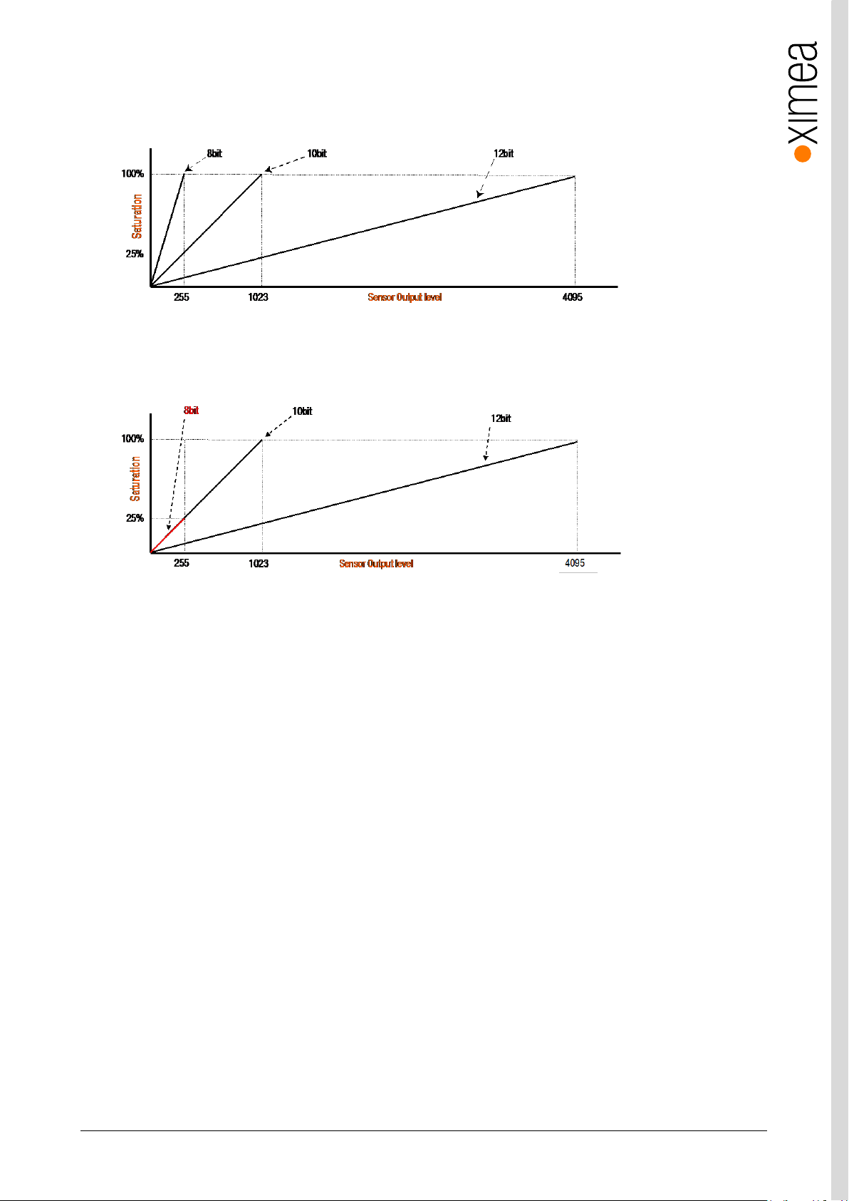
xiC - Technical Manual Version 1.16
77
4.2.5. Digitization bit depth
In case of most cameras changing the sensor digitization bit depth may increases the maximum possible frame rate,
but does not affect the saturation level.
figure 4-1, Saturation vs Sensor output for different digitization bit depths
Cameras featuring 2nd generation of Sony IMX sensors (MC031, MC050, MC089, MC124) have special 8bit digitization mode,
which features same conversion gain as 10bit mode using only ¼ of the saturation. This lead to four times brighter images
compared to 10bit and 12bit modes.
figure 4-2, Saturation vs Sensor output for different digitization bit depths 2nd generation IMX sensors
Page 78
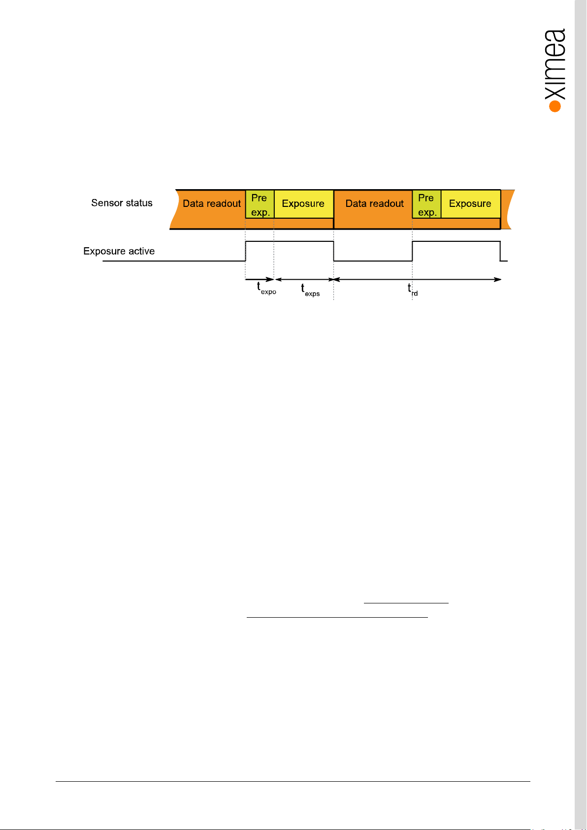
xiC - Technical Manual Version 1.16
78
4.3. Acquisition modes
4.3.1. Free-Run
Also known as continuous acquisition. In this mode the sensor delivers a constant stream of image data at the maximum speed
available by the current bandwidth, without any external trigger. Each image exposure is sequentially started automatically when
possible.
For all sensors the exposure of the next frame overlaps with the data readout of the previous frame.
This Overlapped mode gives the highest number of frames per second (FPS).
figure 4-3, acquisition mode - free run
In this mode the timing depends on the Exposure Time and Data Readout Time.
All xiC cameras support limiting of FPS. When set the camera will limit the frame rate so it does not exceed the set value.
Please see: Frame_Rate_Control: https://www.ximea.com/support/wiki/allprod/Frame_Rate_Control
This is also applicable in case of triggered acquisition.
4.3.2. Trigger controlled Acquisition/Exposure
Unlike in the free-run, each image exposure can also be triggered with an input trigger signal. In this mode, the sensor waits in
stage until the trigger signal arrives. Only then, the exposure of first frame is started, which is followed by the data readout.
Ximea cameras supports several triggered modes along with single image exposure after one trigger. The trigger signal can be
either edge sensitive or level sensitive. In case of level sensitive it can used to control length of exposure or acquisition itself.
Generally trigger sources can be divided in to two groups:
Software Trigger
The trigger signal can be sent to the sensor using a software command. In this case, common system related latencies and
jitter apply.
Hardware Trigger
A hardware trigger can be sent to the sensor using the digital input described in 3.10.3 Optically isolated Digital Input, or nonisolated ports configured as input described in 3.10.5 Non-isolated Digital Lines (-UB and -TC only) Triggering by hardware is
usually used to reduce latencies and jitter in applications that require the most accurate timing.
Page 79
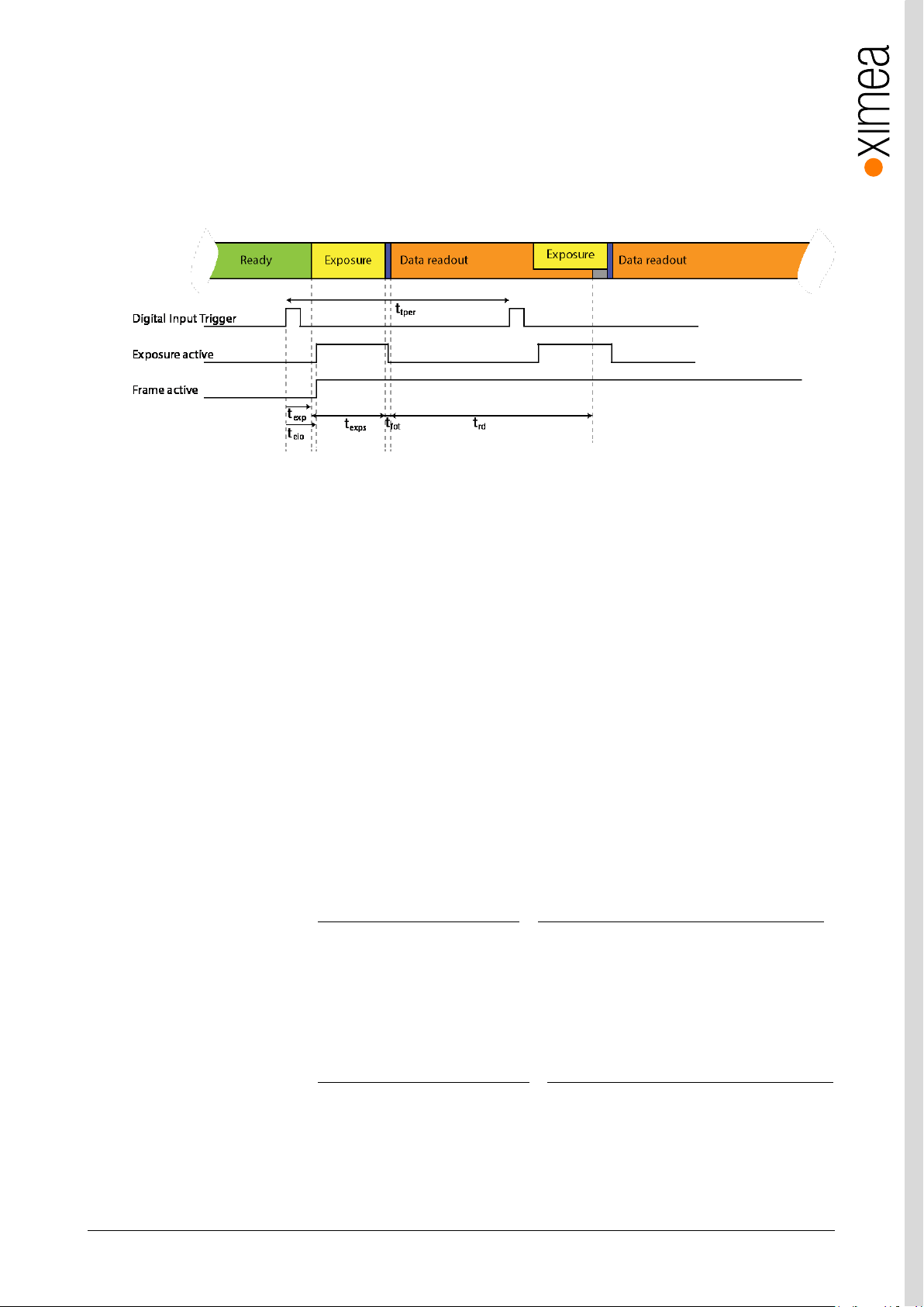
xiC - Technical Manual Version 1.16
79
4.3.2.1. Triggered acquisition - single frame
Sensors support exposure overlapped with readout. When the trigger period (t
) is longer than the exposure plus readout time,
tper
exposure is not overlapped with readout. However when the trigger period is decreased, the sensor will expose the images in
overlap mode. In this case, the frame active signal will be constantly active. The trigger period has to be long enough so the
exposure of next frame does not end sooner than readout of previous frame.
Sensor timing in Exposure Overlapped with Data Readout Mode
figure 4-4, acquisition mode – triggered with overlap
Description:
t
– Trigger (Digital Input) to Exposure Active (Digital Output)
eio
t
– Trigger (Digital Input) to start of exposure
exp
t
– Current Exposure Time set (XI_PRM_EXPOSURE)
exps
t
– Frame overhead time (FOT)
fot
t
– readout time (Readout Time)
rd
t
– readout time of one row (Line period) depends on sensor settings
row
Conditions: Debounce on trigger input line and trigger delay are disabled.
The timing strongly depends on camera settings. Most of the times can be calculated using Camera performance calculator.
The delay between trigger input and start of exposure:
Where:
t
t
– Jitter introduced by synchronization to row sync signal is less than t
jitter
– Delay inside camera caused by internal electronics. This depends on input type.
idelay
row
Please refer to: 3.10.3 Optically isolated Digital Input or 3.10.5 Non-isolated Digital Lines (-UB and -TC only)
The output signaling is then delayed the delay introduced from the output electronic.
Where:
t
– Delay inside camera caused by internal electronics. This depends on output type.
odelay
For minimum trigger period (t
the triggered exposure does not overlap with the readout of the previous frame.
Please refer to: 3.10.4 Optically isolated Digital Output or 3.10.5 Non-isolated Digital Lines (-UB and -TC only)
) the following applies. The next trigger after one is processed needs to be applied so the end of
tper
Page 80
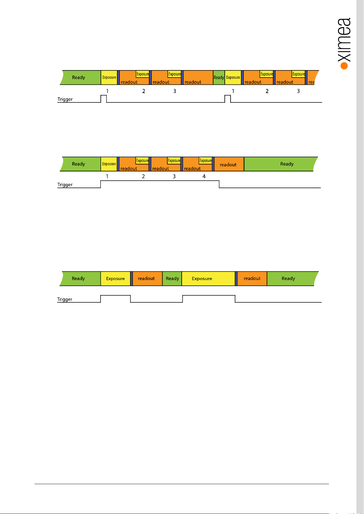
xiC - Technical Manual Version 1.16
80
4.3.2.2. Triggered acquisition - burst of frames
Frame Burst Start
In this mode each trigger pulse triggers defined number of exposed frames.
figure 4-5, triggered burst of frames – frame burst start, number of frames in burst set to 3
Frame Burst Active
If trigger is level sensitive it can be used to control image acquisition.
figure 4-6, triggered burst of frames – frame burst active
Please see: Frame Burst Modes: https://www.ximea.com/support/wiki/allprod/Frame_Burst_Modes
4.3.2.3. Exposure defined by trigger pulse length
In this mode the exposure is defined by trigger pulse length. This can be used to achieve longer exposure than allowed by API.
Also it can be used to trigger several images in sequence with different exposure time. Exposure time is measured and reported
in image metadata.
figure 4-7, Exposure defined by trigger pulse length
Please see: Exposure Defined by Trigger Pulse Length:
https://www.ximea.com/support/wiki/allprod/Exposure_Defined_by_Trigger_Pulse_Length
Page 81
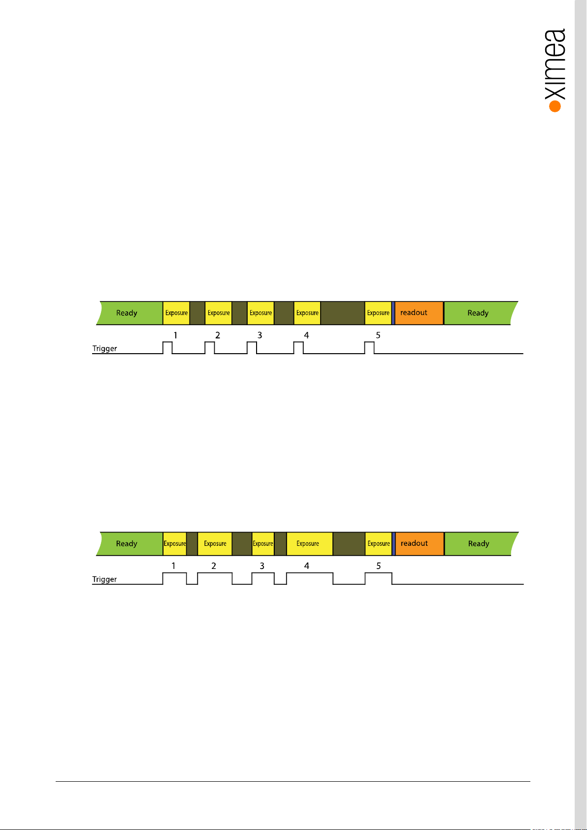
xiC - Technical Manual Version 1.16
81
4.3.2.4. Multiple exposures in one frame
All Sony IMX based xiC models except MC023xG-SY support defined number of exposures exposed into a single frame.
In this mode the number of exposures need to be defined. The number of exposures can be defined using the XiApi parameter
XI_PRM_EXPOSURE_BURST_COUNT. The readout of the frame starts after the last exposure period has finished.
It can operate in two modes:
1. Exposure defined by XiApi parameter "XI_PRM_EXPOSURE"
In this mode the trigger defines the start of the exposure but the length of the exposure is defined by the
XI_PRM_EXPOSURE xiApi parameter. Set exposure length using XI_PRM_EXPOSURE parameter
and set XI_PRM_TRG_SELECTOR to XI_TRG_SEL_EXPOSURE_START.
// Set exposure
xiSetParamInt(xiH, XI_PRM_EXPOSURE, 1000);
// Set the number of times of exposure in one frame
xiSetParamInt(xiH, XI_PRM_EXPOSURE_BURST_COUNT, 5);
// Set trigger selector
xiSetParamInt(xiH, XI_PRM_TRG_SELECTOR, XI_TRG_SEL_EXPOSURE_START);
figure 4-8, Multiple exposures - defined exposure time, number of exposures set to 5
2. Exposure is defined by length of trigger pulse.
In this mode both the start of the exposure as well as the length of the exposure is defined by the trigger pulse. Set
XI_PRM_TRG_SELECTOR to XI_TRG_SEL_EXPOSURE_ACTIVE. The exposure length will be defined by trigger pulse
length.
// Set the number of times of exposure in one frame
xiSetParamInt(xiH, XI_PRM_EXPOSURE_BURST_COUNT, 5);
// Set trigger selector
xiSetParamInt(xiH, XI_PRM_TRG_SELECTOR, XI_TRG_SEL_EXPOSURE_ACTIVE);
figure 4-9, Multiple exposures - exposure time defined by trigger pulse length, number of exposures set to 5
In both above modes there is a short period (FOT) after each exposure during which the next exposure cannot start. In case of
the cameras with IMX sensors this period is 11*line period (the line period depends on various other parameters, see Line
Period in the using Camera performance calculator).
Page 82

xiC - Technical Manual Version 1.16
82
4.4. Camera Parameters and Features
4.4.1. Exposure Time
Also known as shutter speed. This parameter defines the length of the integration period for each frame.
Most CMOS sensors generate the exposure interval internally. For some it is possible to control it by external signaling. The
sensor internal timing depends on the provided system clock. Most sensors use dividers to generate slower clocks for internal
usage.
The minimum exposure time is defined mostly by row times, where the row time (TR) is dependent on various internal settings.
Very few sensors support exposure times equal to zero. There is a defined minimum exposure time as well as minimum steps
between possible exposure times. There is also a maximum exposure time, defined by sensor architecture.
4.4.2. Gain
The gain value influences the analog-to-digital conversion process of the image sensor pipeline and acts as a multiplier of the
output signal. Using gain values greater than 0 will increase the pixel intensities but may also increase the overall noise level.
4.5. Host-Assisted Image Processing Parameters Available in xiAPI.
4.5.1. Auto Exposure – Auto Gain
When AEAG is used, every captured image is evaluated for its mean intensity. Based on the result, the exposure and gain values
are modified with the objective to achieve a target intensity level for the following image. Further, the maximum applicable
exposure and gain values can be defined. Since both, exposure and gain, have an influence on the intensity, the ratio between
those two parameters in their contribution to the algorithm can also be set (exposure priority).
4.5.2. White Balance
Only for color models: The white balance can be adjusted with three coefficients kR, kG and kB, one for each color channel.
These coefficients can be set individually in order to increase or decrease each channel’s contribution and therefore allow the
user to control the color tint of the image.
4.5.2.1. Assisted Manual White Balance
This feature measures the white balance a single time and sets the white balance coefficient to achieve a mean grey (neutral)
tint.
The measurement is performed on the central rectangle of the image, with 1/8th of its width and height. The function expects a
white sheet of paper exposed to 50% of the intensity values (8 Bit RGB values should be around 128) to be visible.
4.5.2.2. Auto White Balance
The white balance is measured across the full image for every 4th image that is acquired and the white balance coefficients are
set to to achieve a neutral colour tint.
4.5.3. Gamma
Only for color models: As a part of the color filtering process, it is possible to adjust the gamma level of the image. The
adjustment can be set separately for the luminosity and the chromaticity.
4.5.4. Sharpness
Only for color models: As a part of the color filtering process, it is possible to adjust the sharpness of the image.
Page 83

xiC - Technical Manual Version 1.16
83
4.5.5. Color Correction Matrix
The color correction matrix is a 4x4-matrix which is applied on each pixel of an image in a host-assisted port-processing step.
This Matrix can be used for example to adjust the brightness, contrast, and saturation.
4.5.6. Sensor Defect Correction
During the manufacturing process, every camera is tested for various type of defects and a list of the measured defect pixels is
created and stored in the camera’s non-volatile memory. This list is then used for the correction of acquired images during
operation. The correction is inactive by default, but can be turned on by the user if a non-processed output is required.
Page 84

xiC - Technical Manual Version 1.16
84
5. Software
5.1. Accessing the Camera
Depending on the target application, the user can choose between several ways of accessing and controlling the camera. These
can be divided into two categories: a programmatic approach, through programming code, or an integrated approach, through a
supported, GUI based software package. The programmatic approach is generally used for the development of a custom
application or image processing pipeline. The integrated approach is favored, if the specific toolset of a certain software
package is sufficient and the camera serves as an integrated capture device.
5.1.1. Proprietary API
All XIMEA cameras are supported by the same unified APIs (application programming interface). The API is a software interface
between the camera system driver and the application. Different APIs are available for different programming environments, e.g.
xiAPI (see 5.7.1 XIMEA APIs) for C/C++ developments and xiAPI.Net for C#/.Net based developments
5.1.2. Standard Interface
As an alternative to the proprietary API, the camera can be accessed through a set of standard interfaces. These interfaces
decouple a specific hardware design (e.g. physical interface) of a camera from its control in software. Therefore multiple camera
classes and types can be used in a unified way.
5.1.2.1. GenICam
GenICam/GenTL provides a camera-agnostic transport layer interface to acquire images or other data and to communicate
with a device. Each camera serves as a GenTL Producer which can be accessed in all software packages that are compatible
with the GeniCam standard, as well as through custom developments which implement this standard interface.
5.1.2.2. USB3 Vision
The USB3 Vision standard not only defines hardware specifications and communication protocols, but also enables a library
vendor or application developer to set up a software stack including their own drivers and the GenICam programming interface.
This allows the usage of any USB3 Vision compliant device while relying on mechanisms for device discovery and identification,
control, and image streaming which are defined by the standard.
5.1.3. Vision Library Integration
All XIMEA cameras are compatible with the most advanced vision and image processing libraries. For GUI based software
packages, the cameras can be directly accessed without the need of programming. Code libraries are generally used in
conjunction with one of our APIs, in order to add additional functionality (e.g. image processing, communication, data storage).
Page 85
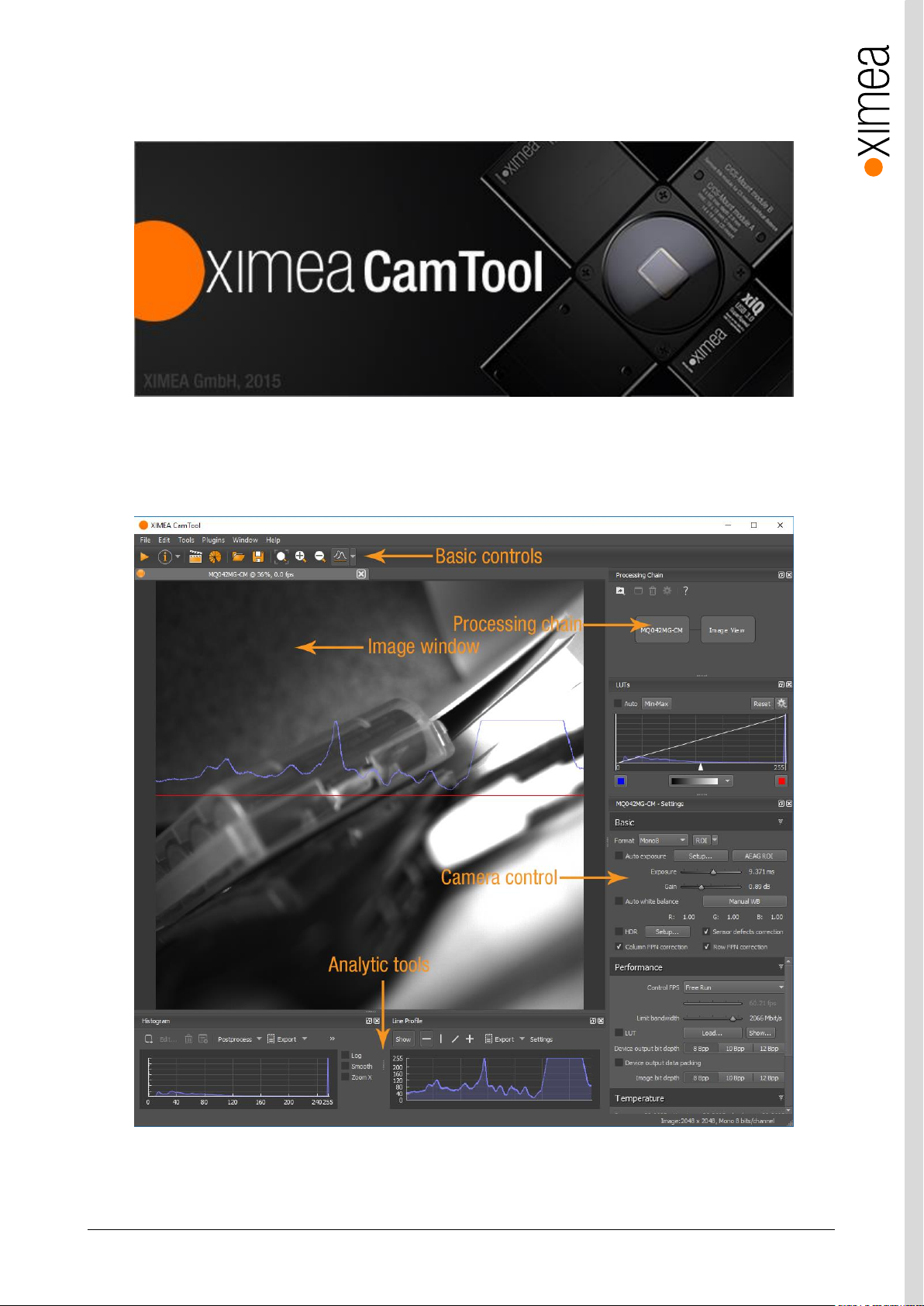
xiC - Technical Manual Version 1.16
85
5.2. XIMEA CamTool
The CamTool is a cross-platform application showcasing the features of all XIMEA camera families.
Short description
It runs on Windows, Linux, macOS systems offering a substantial imaging tool set, which can be further extended with custom
modules using a plugin infrastructure. CamTool is based on Qt for the UI and xiAPI for the camera control. Its camera settings
menu resembles the parameter set of the xiAPI
figure 5-1, CamTool Layout
Page 86

xiC - Technical Manual Version 1.16
86
Functions
to see live image from multiple XIMEA cameras connected
control the camera parameters
store of camera image and video
analyze the image properties
histogram and line profile
image averaging, image flip/mirror
software trigger timer, save/load camera and program settings
LUT (Look up table)
Lua scripting
CamTool allows to operate all connected cameras simultaneously. In this case all control are layered for the cameras. Basic
controls are placed as tabs in upper part of the window. Image window can be detached from application if needed. Amount of
visible camera controls depend on visibility level which can be set in EditOptions.
For more information please refer to: https://www.ximea.com/support/wiki/allprod/XIMEA_CamTool
Page 87
xiC - Technical Manual Version 1.16
87
5.3. Supported Vision Libraries
For an up-to-date listing of the supported vision libraries and software packages, visit our web site
http://www.ximea.com/support/projects/vision-libraries/wiki.
5.3.1. Libraries maintained by XIMEA
All cameras listed in the section Products are supported with these libraries.
XIMEA commits to update the API within twelve months after a new major release.
XIMEA warranties backwards compatibility of these software packages for two major releases.
5.3.1.1. MathWorks MATLAB
MathWorks® is the leading developer and supplier of software for technical computing and Model-Based Design.
More: http://www.mathworks.de/ or https://www.ximea.com/support/wiki/vision-libraries/MathWorks_Matlab
5.3.1.2. MVTec HALCON
HALCON is the comprehensive standard software for machine vision with an integrated development environment (IDE) that is
used worldwide.
More: http://www.mvtec.com/halcon/ or https://www.ximea.com/support/wiki/vision-libraries/MVTec_HALCON
5.3.1.3. National Instruments LabVIEW Vision Library
LabVIEW is a graphical programming environment.
More: http://www.ni.com/labview/
https://www.ximea.com/support/wiki/vision-libraries/National_Instruments_LabVIEW
5.3.1.4. OpenCV
OpenCV is an open source library of programming functions mainly aimed at real time computer vision, developed by Intel and
now supported by Willow Garage.
More: http://opencv.willowgarage.com/wiki/
https://www.ximea.com/support/wiki/vision-libraries/OpenCV
Page 88
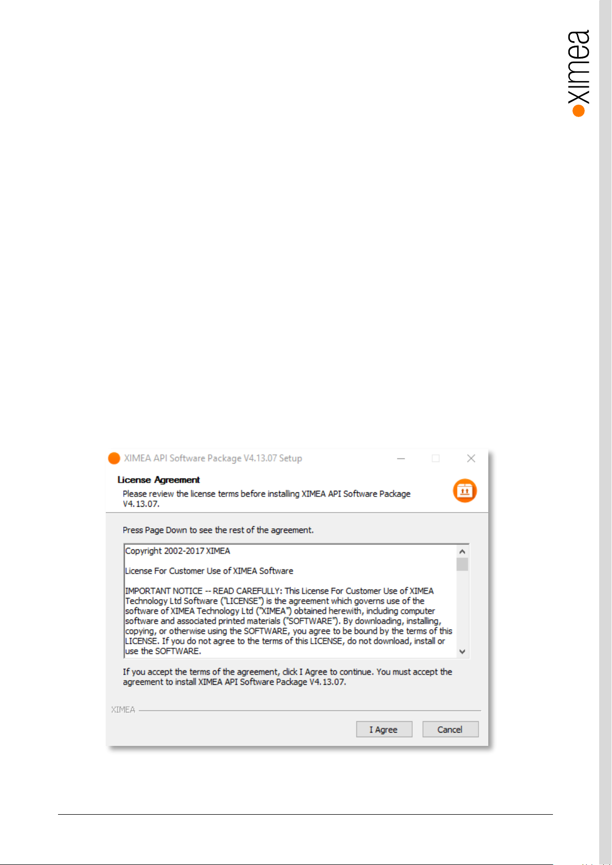
xiC - Technical Manual Version 1.16
88
5.4. XIMEA Windows Software Package
XIMEA API Software Package can be installed on: Microsoft Windows 10, Microsoft Windows 8, Microsoft Windows 7 (and
Microsoft Windows 7 Embedded), Microsoft Windows Server 2008 R2.
5.4.1. Contents
The package contains:
• OS Drivers of all XIMEA camera types for OS Microsoft Windows XP SP3 32bit, Windows 7 32/64 bit, Windows 8 32/64
bit, Windows Server 2008 R2 x86-64, Windows 10 32/64 bit.
• APIs (xiAPI, xiAPI.NET, xiApiPython)
• Examples
• CamTool
• xiCop
• GenTL Producer - for connection of GenTL Consumer applications.
• Vision Libraries integration demonstrations:
o NI LabView interface - xiLib
5.4.2. Installation
• Download and execute the XIMEA API Software Package installer (EXE-file, approximate size 100 MB):
http://www.ximea.com/downloads/recent/XIMEA_Installer.exe
• Read the License Agreement.
• Start the installer
Be sure that you have administrator privileges or start the Installer with administrator rights (right click and select “run as
administrator):
figure 5-2, XIMEA Windows Software Package installation - 1
Page 89
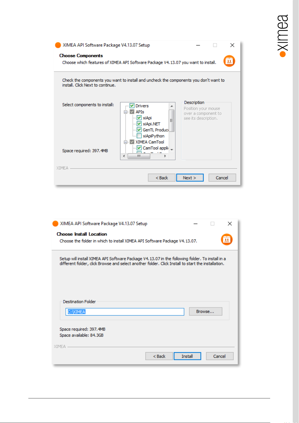
xiC - Technical Manual Version 1.16
89
• Select the Software components you want to install. You can uncheck the components you don't want to install, but it is
recommended to leave them all checked.
figure 5-3, XIMEA Windows Software Package installation - 2
• Specify the install location - you can leave the default location or change it to your desired location.
figure 5-4, XIMEA Windows Software Package installation - 3
Page 90
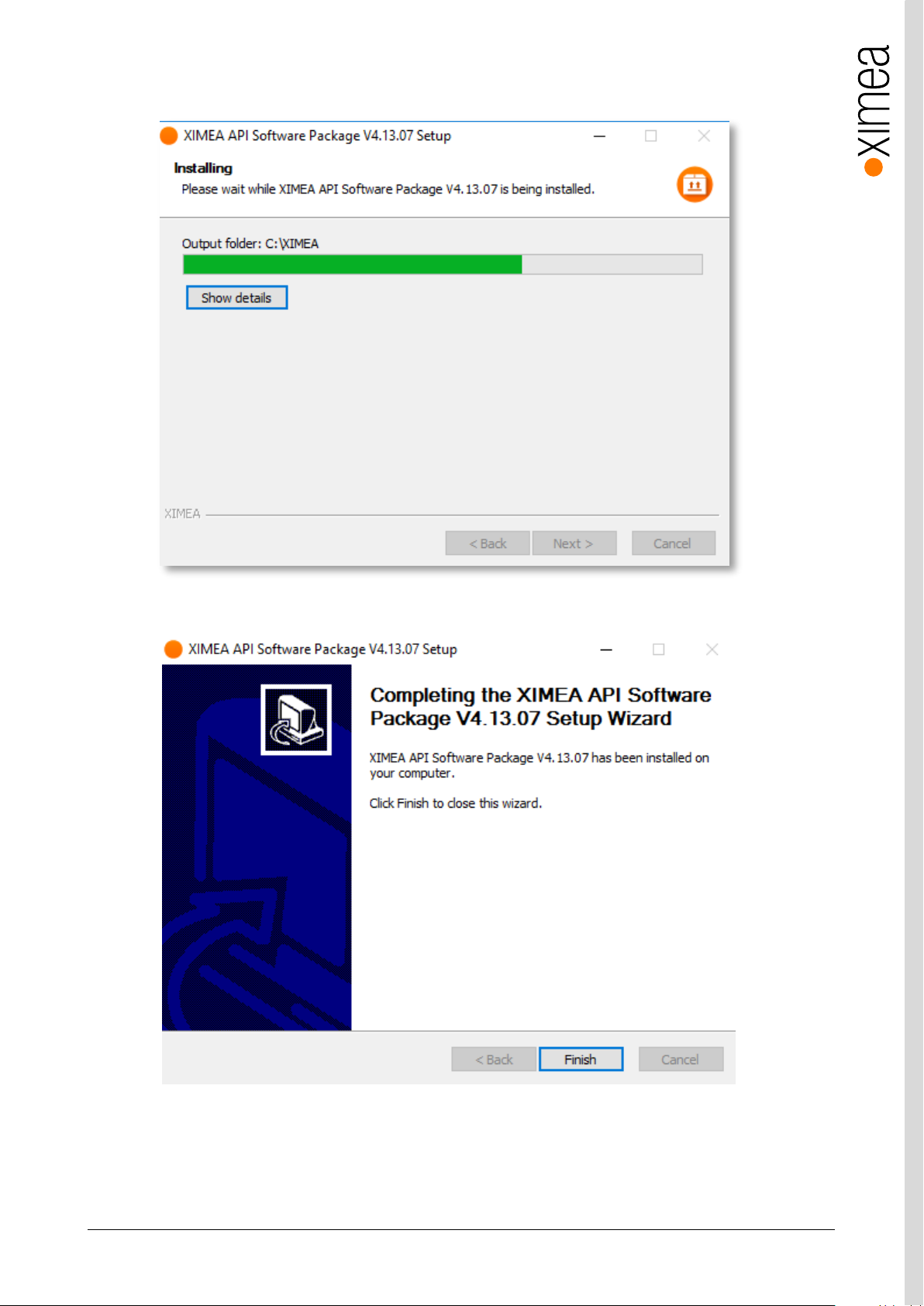
xiC - Technical Manual Version 1.16
90
• Now the XIMEA API Software Package should start copying files, updating System Variables and installing drivers if
necessary.
figure 5-5, xiAPI installation, Windows - 4
• Installation is completed.
figure 5-6, xiAPI installation, Windows - 5
• Finish.
Page 91
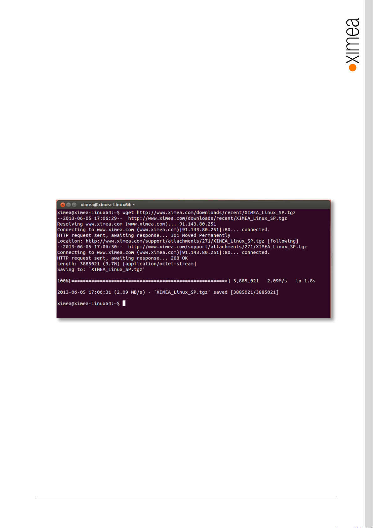
xiC - Technical Manual Version 1.16
91
5.5. XIMEA Linux Software Package
XIMEA Linux Software Package is tarred installer with files that can be run on Linux Ubuntu 14.04 and 16.04 (32 and 64 Bit)
and newer releases.
5.5.1. Contents
The package contains:
• Driver (beta version) for XIMEA USB2 and USB3 cameras
• xiAPI
• Ximea CamTool
• Examples:
o xiSample - sample showing basic image acquisition in xiAPI
5.5.2. Installation
• Download XIMEA Linux Software Package
wget http://www.ximea.com/downloads/recent/XIMEA_Linux_SP.tgz
figure 5-7, XIMEA Linux Software Package installation - 1
• Untar
tar xzf XIMEA_Linux_SP.tgz
cd package
• Start installation script
./install
Page 92
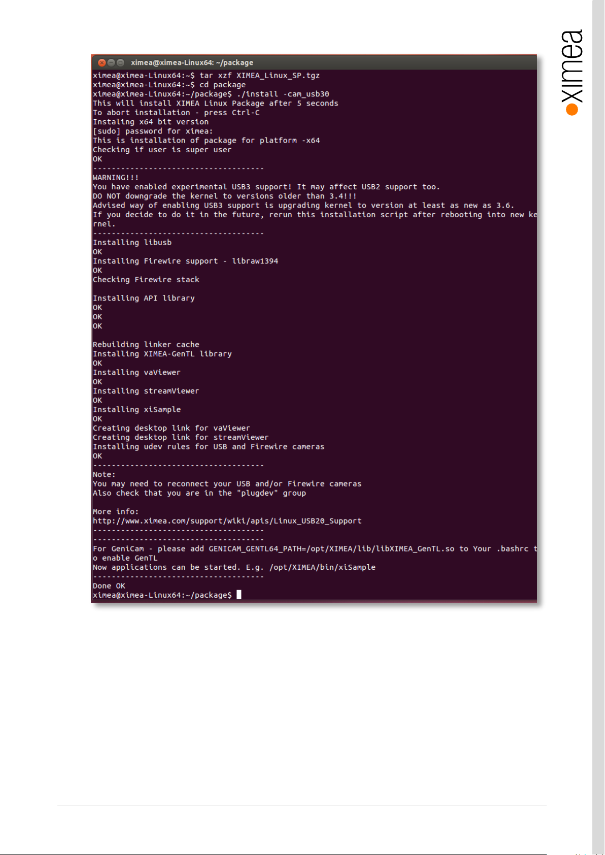
xiC - Technical Manual Version 1.16
92
figure 5-8, XIMEA Linux Software Package installation - 2
1) Note: If logged in user is not root, you will be asked for your password to get root access, because the installation runs with
root account using sudo.
Page 93
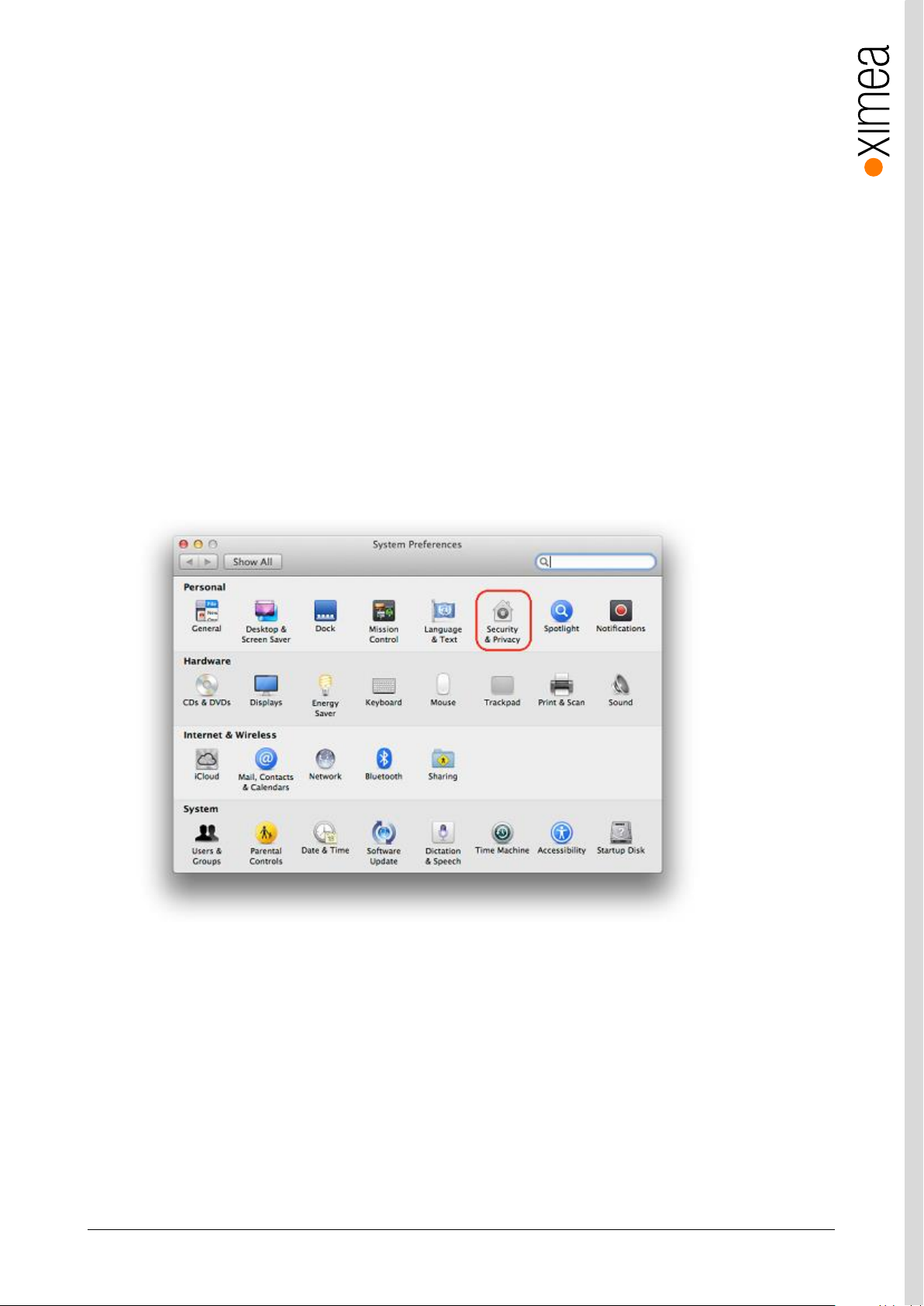
xiC - Technical Manual Version 1.16
93
5.6. XIMEA macOS Software Package
XIMEA macOS Software Package is native DMG installer that can be run on macOS 10.8 (Mountain Lion) or newer.
5.6.1. Contents
The package contains:
• Driver (beta version) for XIMEA USB2 and USB3 cameras
• xiAPI
• XIMEA CamTool
• Examples:
o xiSample - sample showing basic image acquisition in xiAPI
5.6.2. Installation
Before installing XIMEA macOS Software Package it may be necessary to modify security settings on your computer. The new
feature of OS X 10.8 called GateKeeper can prevent you from using our macOS Software Package due to the fact that the
current version is unsigned.
Open System Preferences application and click on Security & Privacy.
figure 5-9, XIMEA macOS Software Package installation - 1
Page 94
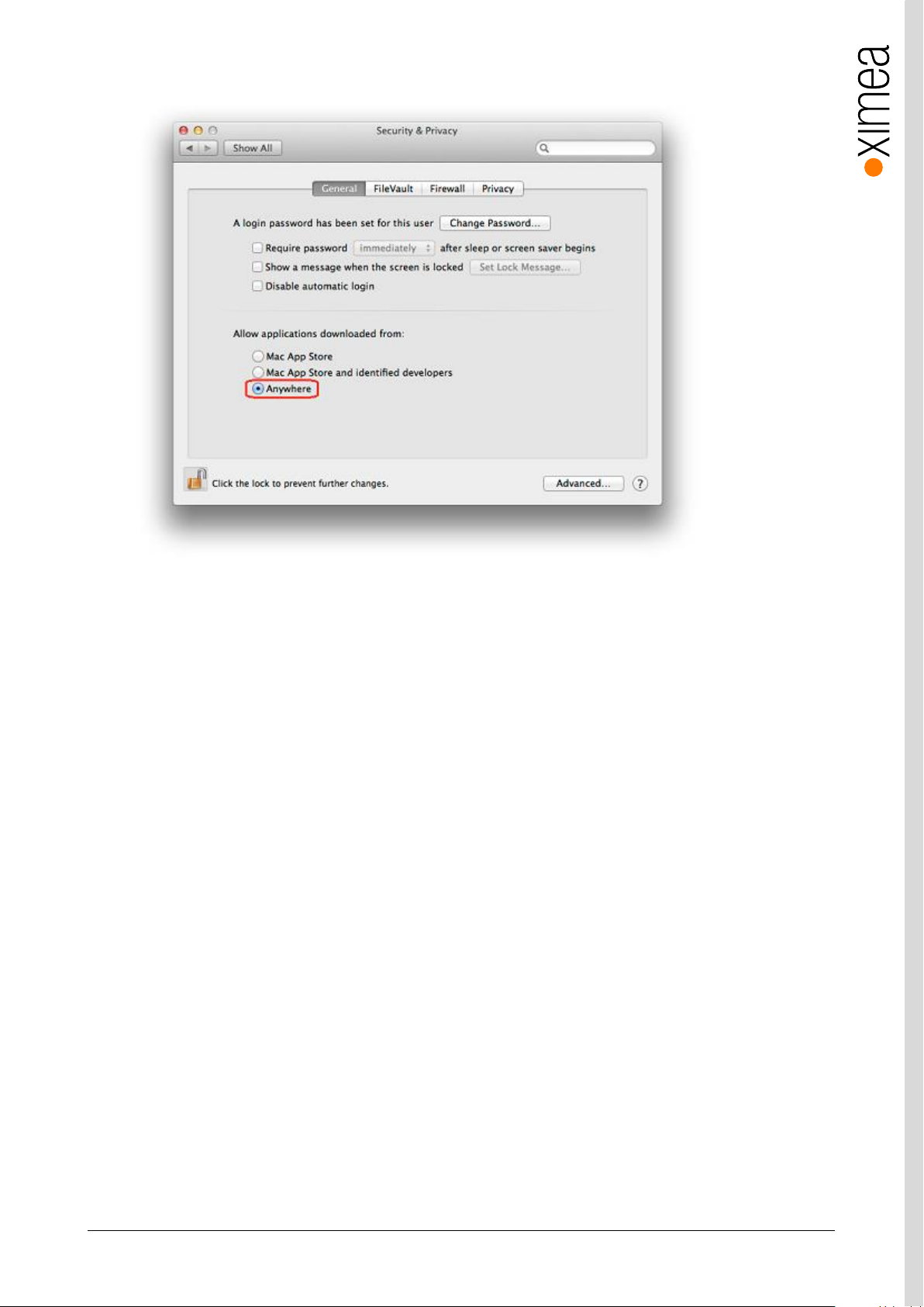
xiC - Technical Manual Version 1.16
94
On the General Tab select the option Anywhere under Allow applications downloaded from:
figure 5-10, xiAPI installation, MacOS - 2
• Download XIMEA macOS Software. Package: http://www.ximea.com/downloads/recent/XIMEA_OSX_SP.dmg
• Mount it by double-clicking this file in Finder.
• Run the install script to install XiAPI on your macOS system
• A window with package contents will open.
5.6.3. Start XIMEA CamTool
• Connect camera
• Start Applications / XIMEA CamTool
• Start acquisition by clicking on orange triangle at upper left corner of CamTool
Page 95

xiC - Technical Manual Version 1.16
95
5.7. Programming
5.7.1. XIMEA APIs
• xiAPI - Streamlined API. The standard API for C/C++ based projects, see 5.7.2 xiAPI Overview.
• xiAPI.NET - Managed .NET Common Language Runtime (CLR) API.
xiAPI.NET is designed as a wrapper around xiAPI and therefore shares most of its functionality.
• xiApiPython – Integrated API into PYTHON.
5.7.2. xiAPI Overview
xiAPI stands for XIMEA Application Programming Interface. It is a common interface for all XIMEA cameras.
Architecture
API is a software interface between the camera system driver and application.
• On Windows: xiAPI is compiled into xiapi32.dll or xiapi64.dll
• On Linux: xiAPI is compiled into /usr/lib/libm3api.so
Installation
xiAPI is part of all current XIMEA software packages for Windows, Linux and MacOS.
For information on the software packages, see 5 Software
5.7.3. xiAPI Functions Description
The core of xiAPI consists of the following functions, which allow controlling of the camera functionality.
// get the number of discovered devices.
XI_RETURN xiGetNumberDevices(OUT DWORD *pNumberDevices);
// open interface
XI_RETURN xiOpenDevice(IN DWORD DevId, OUT PHANDLE hDevice);
// get parameter
XI_RETURN xiGetParam(IN HANDLE hDevice, const char* prm, void* val,
DWORD * size, XI_PRM_TYPE * type);
// set parameter
XI_RETURN xiSetParam(IN HANDLE hDevice, const char* prm, void* val,
DWORD size, XI_PRM_TYPE type);
// start the data acquisition
XI_RETURN xiStartAcquisition(IN HANDLE hDevice);
// acquire image and return image information
XI_RETURN xiGetImage(IN HANDLE hDevice, IN DWORD TimeOut, INOUT XI_IMG
* img);
// stop the data acquisition
XI_RETURN xiStopAcquisition(IN HANDLE hDevice);
// close interface
XI_RETURN xiCloseDevice(IN HANDLE hDevice);
Page 96

xiC - Technical Manual Version 1.16
96
5.7.4. xiAPI Parameters Description
For a complete list of available parameter, please visit the xiAPI online manual at
http://www.ximea.com/support/wiki/apis/XiAPI_Manual
Note: Since xiAPI is a unified programming interface for all of XIMEA‘s cameras, not all of the described parameters apply for
every camera and sensor model.
All functions in xiAPI return status values in form of the XI_RETURN structure which is defined in xiApi.h. If a parameter is not
supported by a certain camera, the return value will represent a respective error code (e.g. 106 - Parameter not supported).
5.7.5. xiAPI Examples
5.7.5.1. Connect Device
This example shows the enumeration of available devices. If any device was found the first device (with index 0) is opened.
HANDLE xiH = NULL;
// Get number of camera devices
DWORD dwNumberOfDevices = 0;
xiGetNumberDevices(&dwNumberOfDevices);
if (!dwNumberOfDevices)
{
printf("No camera found\n");
}
else
{
// Retrieving a handle to the camera device
xiOpenDevice(0, &xiH);
}
5.7.5.2. Parameterize Device
This example shows how an exposure time is set. Next, the maximum possible downsampling rate is retrieved and the result is
set as new downsampling rate.
// Setting "exposure" parameter (10ms)
int time_us = 10000;
xiSetParam(xiH, XI_PRM_EXPOSURE, &time_us, sizeof(time_us),
xiTypeInteger);
// Getting maxium possible downsampling rate
int dspl_max = 1;
xiGetParamInt(xiH, XI_PRM_DOWNSAMPLING XI_PRM_INFO_MAX, &dspl_max);
// Setting maxium possible downsampling rate
xiSetParamInt(xiH, XI_PRM_DOWNSAMPLING, dspl_max);
Page 97
xiC - Technical Manual Version 1.16
97
Digital Output
Exposure Active
Data Only
PC with
application
Digital Input
Trigger
5.7.5.3. Acquire Images
This example shows how the acquisition is started on the device with the handle xiH, ten images are acquired in a row and the
acquisition is stopped.
xiStartAcquisition(xiH);
#define EXPECTED_IMAGES 10
for (int images=0;images < EXPECTED_IMAGES;images++)
{
// getting image from camera
xiGetImage(xiH, 5000, &image);
printf("Image %d (%dx%d) received from camera\n", images,
(int)image.width, (int)image.height);
}
xiStopAcquisition(xiH);
5.7.5.4. Control Digital Input / Output (GPIO)
Hardware Trigger and Exposure Active output
In this setup each image is triggered by a Digital Input Trigger. After the image is triggered, it can be transferred using
xiGetImage.
This setup ensures a low latency between the trigger signal and image Exposure start. This time should be less than 10µs.
figure 5-11, GPIO - schematic
Camera
HANDLE xiH;
xiOpenDevice(0, & xiH);
// select trigger source
xiSetParamInt(xiH, XI_PRM_TRG_SOURCE, XI_TRG_EDGE_RISING);
// select input pin 1 mode
xiSetParamInt(xiH, XI_PRM_GPI_SELECTOR, 1);
xiSetParamInt(xiH, XI_PRM_GPI_MODE, XI_GPI_TRIGGER)
// set digital output 1 mode
xiSetParamInt(xiH, XI_PRM_GPO_SELECTOR, 1);
xiSetParamInt(xiH, XI_PRM_GPO_MODE, XI_GPO_EXPOSURE_ACTIVE);
xiStartAcquisition(handle1);
// Trigger signal should start image exposure within timeout
#define TIMEOUT_IMAGE_WAITING_MS 10000
xiGetImage(handle, TIMEOUT_IMAGE_WAITING_MS, &image);
// process image here…
Page 98

xiC - Technical Manual Version 1.16
98
5.7.6. xiAPI Auto Bandwidth Calculation
xiAPI uses Auto Bandwidth Calculation (ABC) before the opening of each camera by default. After the measurement, 90% of the
measured value is used as the maximum allowed transfer speed of the camera to ensure the stability of transfer.
It is important to set this parameter to XI_OFF to ensure highest possible data transfer speed.
To disable ABC, the application should set parameter XI_PRM_AUTO_BANDWIDTH_CALCULATION to XI_OFF before the first
xiOpenDevice is used. This setting disabled ABC and the camera stream is not limited.
5.7.7. USB3 Vision
For more information on programing according the USB3 VISION standard, please visit the standard’s website at
http://www.visiononline.org/vision-standards-details.cfm?type=11
5.7.8. GenICam
For more information on programing according the GenICam standard, please visit the standard’s website at
http://www.emva.org/standards-technology/genicam/
Page 99
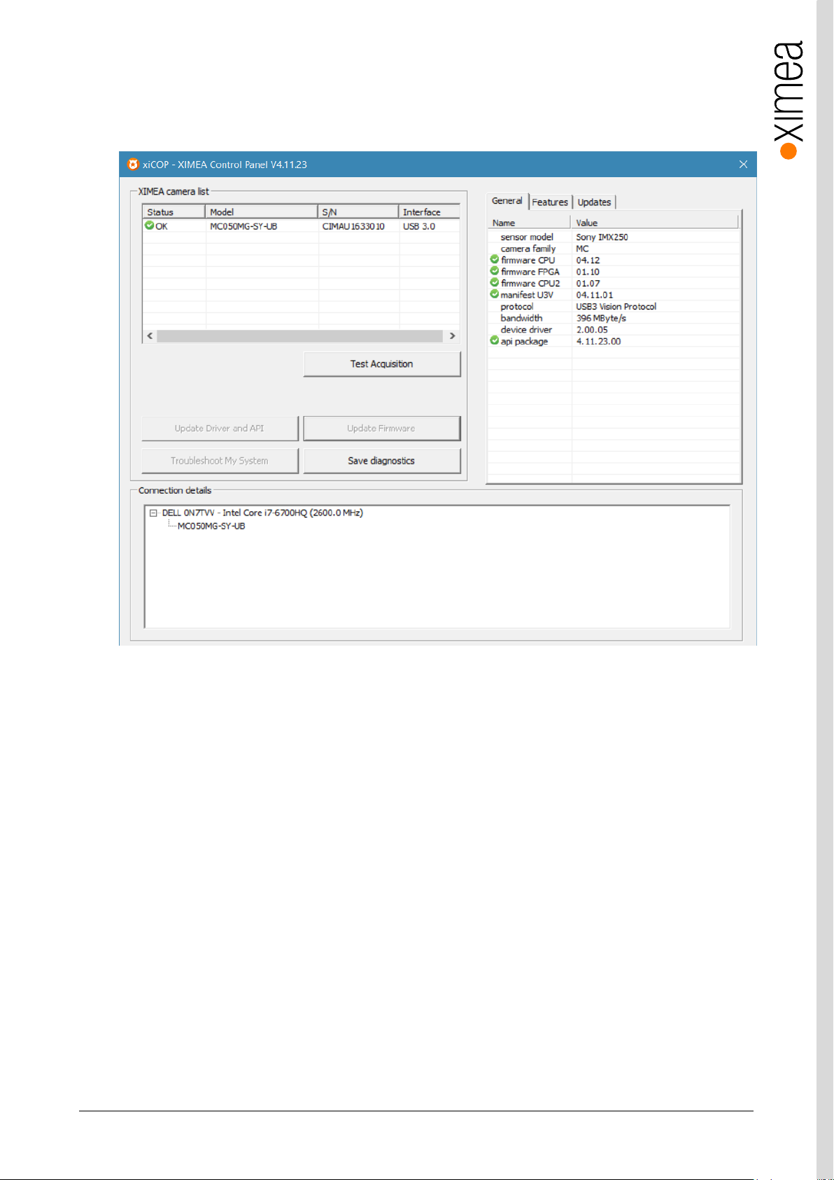
xiC - Technical Manual Version 1.16
99
5.8. XIMEA Control Panel
The XIMEA Control Panel (xiCOP), is a diagnostics and management tool for all XIMEA cameras.
xiCOP is currently only available for Windows operating system.
figure 5-12, xiCOP
Features
• Facilitates diagnostics of system performance bottlenecks.
xiCOP is capable of retrieving the system’s hardware tree, thus problematic hardware configurations can be identified.
• Diagnosis of firmware and software compatibility.
xiCOP checks relevant firmware and software versions and warns if a component is not up-to-date.
• List all currently attached XIMEA devices and their features.
• Suggests solution for diagnosed issues.
• One click update to the latest XIMEA API Software Package.
• One click update of firmware in selected cameras.
Page 100
xiC - Technical Manual Version 1.16
100
Step no:
Description
1
Click on the button “Troubleshoot My System” and follow the instructions that are suggested.
2
If step 1 does not lead to a positive result, please click the button “Save diagnostics”. Keep the
diagnostic file ready for providing it to support.
3
Contact your local dealer where you bought the camera either by phone or by email for first level
support. He will decide if he can help you immediately or if more information is necessary for initiating
the next steps.
6. Appendix
6.1. Troubleshooting and Support
This chapter explains how to proceed, if you have issues in getting your xiC camera to a proper operation.
At first, please make sure, that you have installed the latest version of the following XIMEA software:
• XIMEA Windows Software Package http://www.ximea.com/downloads/recent/XIMEA_Installer.exe
Please make sure, that you have connected your xiC camera with the XIMEA USB 3.0 cable to an appropriate USB 2.0 or USB
3.0 port. Ensure that the connections are carefully locked. Follow the instructions described in chapter 5.2 XIMEA CamTool (run
the xiC camera with the Ximea CamTool). In case that you still have issues, please read the following chapters.
6.1.1. Worldwide Support
We offer worldwide first level support to you by our partners.
Please refer to your local dealer if you need technical support for your xiC camera.
6.1.2. Before Contacting Technical Support
There are a few steps to take before contacting your local dealer for technical support. In case you cannot display images from
your xiC camera, please open the XIMEA xiCOP software (please see 5.8 XIMEA Control Panel). It will immediately start
searching for connected cameras. Your camera will appear in the XIMEA camera list on the upper left side of the xiCOP window
if it is connected properly and your USB interface meets the minimum system requirements described in 4.1 System
Requirements. If the camera does not appear, please proceed with the following steps:
table 6-1, use xiCOP before contacting technical support
6.1.3. Frequently Asked Questions
In this manual, we can list only a few FAQ. For more and updated information, please also note:
• Frequently Asked Questions
http://www.ximea.com/support/wiki/allprod/Frequently_Asked_Questions
• Knowledge Base http://www.ximea.com/support/wiki/allprod/Knowledge_Base
6.1.3.1. What is USB 3.1 Gen 1 SuperSpeed?
USB 3.1 Gen 1 revision of Universal Serial Bus (USB) standard boosts transfer speed of 5Gb/s and enables delivery of up to
4.5W of power to the target device. It uses communication technology similar to that of PCI Express Gen2.
 Loading...