

Page 1

Page 2
No Rules Power
A
Introduction.........................................................................................................2
Product Features.................................................................................................3
B
Accessary Kits.....................................................................................................4
C
Product Information.............................................................................................5
D
E
Connectors & Modularized Cable Management.................................................5~7
F
Installation......................................................................................................8~9
G
+12V Rail Distribution and PCI-E Connectors..........................................................9
H
SPEC Table..................................................................................................10~12
I
Other Specification............................................................................................13
J
Trouble Shooting.................................................................................................13
Einführung........................................................................................................14
A
Leistungsmerkmale................................................................................................15
B
Zubehör .. ....... ....... ....... .............................. ....... ....... ....... ....... ....... ....... .....16
C
Produktinformationen ...........................................................................................17
D
Anschlüsse und modularisierte Kabelführung ...............................................17~19
E
Installation....................................................................................................20~21
F
+12V-Ra il -Belegung und PCI- E- St ec ker.... .. ............................. .. .. .. .. .. .. ..........21
G
Technische Daten.................................................................................................22~24
H
Sonstige technische Daten...........................................................................................25
I
Fehlerbehebung.................................................................................................25
J
はじめに......................................................................................................................26
A
製品の特徴...................................................................................................................27
B
パッケージ内容.............................................................................................................28
C
製品情報......................................................................................................................29
D
コネクタおよびモジュール化ケーブルの管理................................................................29~32
E
インストール..........................................................................................................32~33
F
+12V レール分配と PCI-E コネクタ....................................................................................33
G
仕様表..................................................................................................................34~36
H
その他の仕様................................................................................................................37
I
トラブルシューティング.................................................................................................37
J
Introducción................................................................................................................38
A
Características del producto.........................................................................................39
B
Kits de accesorios........................................................................................................40
C
Información del producto...............................................................................................41
D
Conectores y organizador de cables modularizado.....................................................41~43
E
Instalación............................................................................................................44~45
F
Distribución de vías de +12V y conectores PCI-E.............................................................45
G
Otras especificaciones...........................................................................................46~48
H
Solución de problemas..................................................................................................49
I
Contacte con nosotros.................................................................................................49
J
簡介............................................................................................................................50
A
產品特色......................................................................................................................51
B
附屬配件 ...........................................................................................................52
C
產品資 訊.........................................................................................................53
D
接頭及模組化輸出電源..............................................................................................53~55
E
安裝.....................................................................................................................56~57
F
多組+12V電源配置 及PCI-E接頭........................................................................................57
G
規格表..................................................................................................................58~60
H
其他規格......................................................................................................................61
I
疑難排解......................................................................................................................61
J
TABLE OF CONTENTS
Page 3

INTRODUCTION
A3B
Statement
We live up to the promise of XIGMATEK logo in our unending quest for excellence.
Shall you have any suggestion or comments, please access our website:
Http://www.xigmatek.com
or e-mail to:
support@xigmatek.com
We appreciate your kindly feedback and you will receive the prompt response from
our customer service team.
Please take the time in familiarizing yourself with the power supply, its connectors
and the contents of this manual before proceeding with the installation of the
power unit. You will need a Philips crosshead screwdriver, perhaps your PC case
manual and most certainly your motherboard manual.
Should you have any questions regarding the content of the manual, please contact
XIGMATEK directly. Failure to follow the proper procedures may cause severe
bodily harm or PC component damage.
Warnings and Cautions
1.Do not pull the AC power cord when the power supply is in use or the damages
to the components will occur.
2.Do not store the Power Supply in high humidity and high temperature
environment.
3.When using No Rules Power Cable management power supply under
testing conditions where the power supply unit is not installed in a PC with its
components, please follow the steps below:
•Please take a paper clip and untwist it.
•Make sure the power supply unit is in the “OFF” position.
•Locate the 20+4 pin motherboard connector from the power supply unit.
•Plug one side of the paper clip into the green wire hole.
•Plug the other side of the paper clip into any of the black wire holes.
•Turn on the PSU to see if the power supply fan(s) turn(s) on.
4.High voltages exist in the power supply. Do not open the power supply case
unless you are an authorized service technician or electrician.
5.All warrantees and guarantees shall be voided should there be a failure to comply
with any of the warnings and cautions covered in this manual.
2
Page 4

PRODUCT FEATURES
Product Features
1.8 pin PCI-E Connector NEW!!
No Rules Power supplies come with three of the latest 8-pin PCI-E connectors
required for the next generation NVIDIA and ATI graphics cards. These new
defined 8-pin connectors are downward compatible with the existing 6-pin PCI-E
connectors with an 8 pin to 6 pin converter. Thus, with the included three 6-pin/
8-pin connectors, No Rules Power support up to three high-end graphic cards.
2.Excellent Efficiency (up to 87%)
No R ules Power provide excellen t efficie ncy and henc e reducin g energ y
consumption. That in return reduces customers’ electricity bill.
3.140mm Ball-Bearing Fan
The 140mm ball bearing fan effectively increases the airflow inside the PSU and
decreases the ambient temperature.
4.Extremely good voltage regulation (±3%)
This feature allows tighter load regulation (±3%) than other power supplies (±5%)
and increase system voltage stability.
5.MTBF > 120,000 hours (Highly reliable)
120,000 hours of MTBF (Mean Time between Failures) goes above and beyond all
ATX specifications.
6.Four Independent +12V rails
Four independent +12V rails are provided to support the high-end graphic card
and PC system.
7.Cable Management
Cable Management enables users to remove unused cables and significantly
improves the airflow in the chassis.
8.Industrial grade components (capacitor, transformer, etc)
All components are specially designed for industrial environment and extreme
conditions.
9.Hi-Tech Black Coating
With special Hi-Tech Black coating, No Rules Power looks professional, elegant
and unique.
10.High +5VSB Output
Built-in higher +5VSB (from 2A to 3.5A (PS-ON status)) supports up to 12
USB devices. Also, even the system is power off, USB devices can still be
charged by the 3A sustained output.
Page 5
ACCESSARY KITS
C
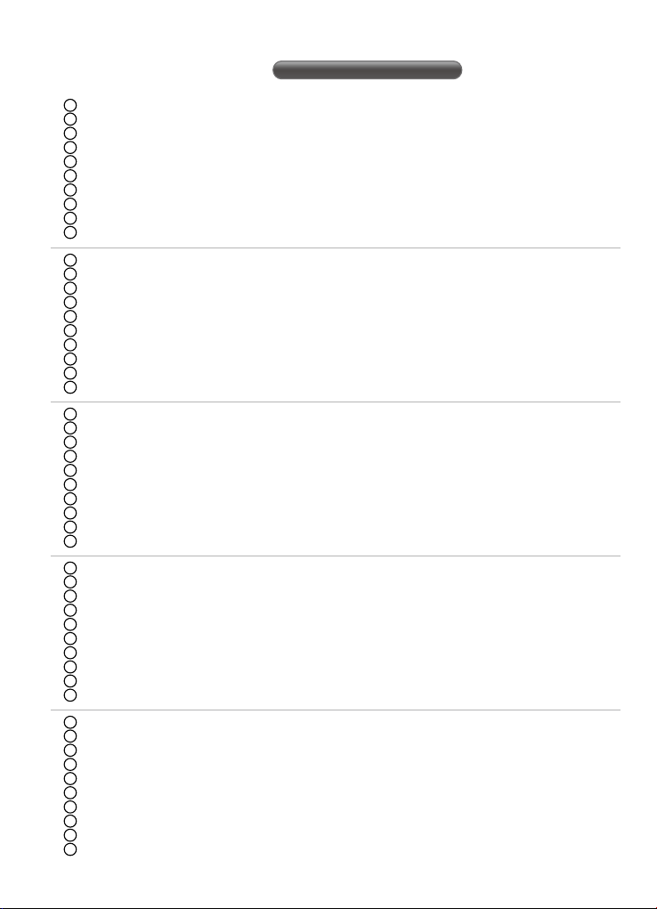
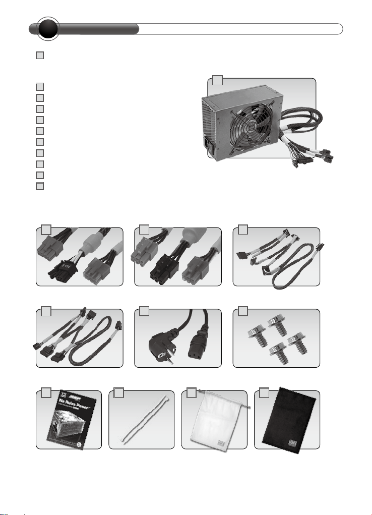
No Rules Power supply unit
1
(w/one 20+4 pin main power connector, one 4+4 pin+
12V power connector, and one 8 pin powerconnector)
8 pin PCI-E connector
2
6 pin PCI-E connector
3
5 pin SATA connector
4
4 pin peripheral connector
5
AC Input power cord
6
4 mounting screws
7
8
User manual
9
Cable ties
10
Power supply dust bag
11
Cable kits bag
One power supply unit(w/one20+4pin main
power connector,one 4+4pln+12V) power
connector, and one 8pln power connector)
1
2
5
8
4
6 7
9
10 11
43
Page 6
PRODUCT INFORMATION
D
1.OUTPUT & INPUT VOLTAGE
2.1INPUT VOLTAGE:100V~240V 47HZ~63HZ
3.1.2 OUTPUT VOLTAGE:
Model / Set
NRP-HC1001 30A 28A 20A 20A 36A 36A 0.8A 3.5A 1000W
NRP-HC1201 30A 28A 20A 20A 36A 36A 0.8A 3.5A 1200W
NRP-HC1501 30A 30A 20A 20A 40A 40A 0.8A 3.5A 1500W
E
+3.3V +5V +12V1+12V2+12V3+12V4-12V +5Vsb
CONNECTORS & MODULARIZED CABLE MANAGEMENT
Total
Power
Connectors
Main Power
Model / Set
NRP-HC1001 1 1 1 8 8 2 3 3
NRP-HC1201 1 1 1 8 8 2 3 3
NRP-HC1501 1 1 1 8 8 2 3 3
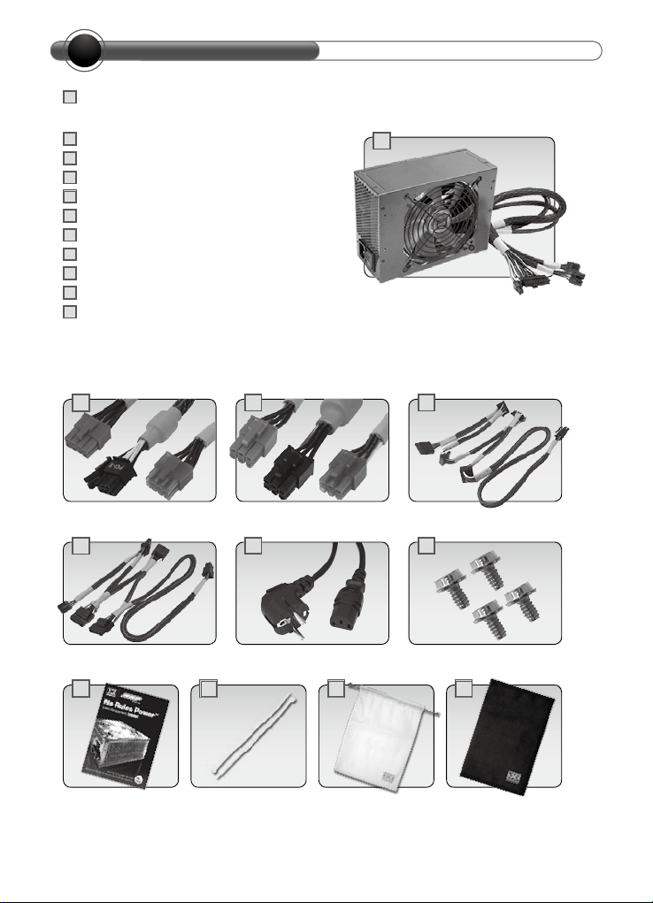
Connector
(20+4 pin)
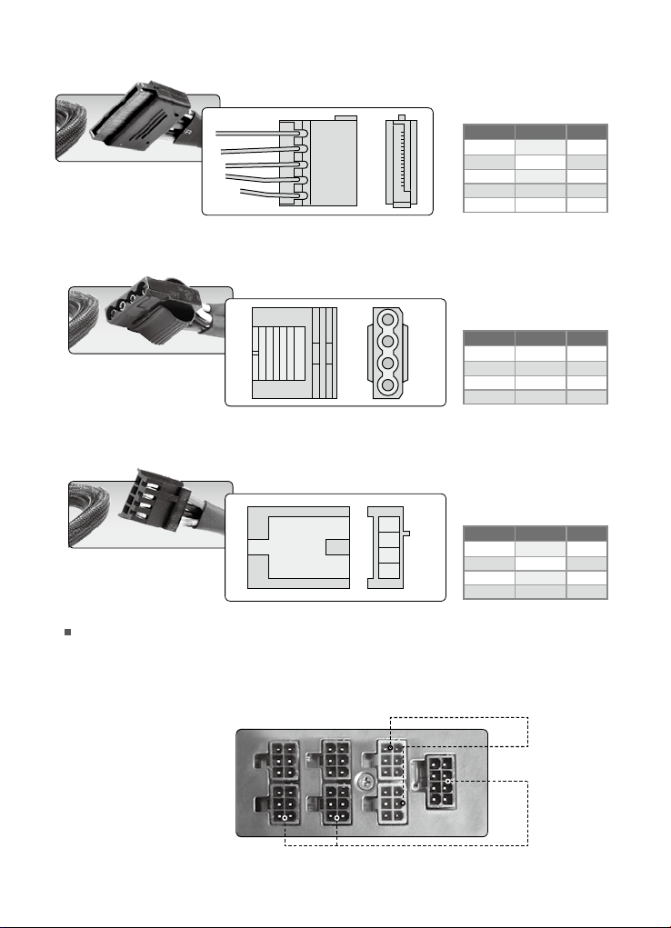
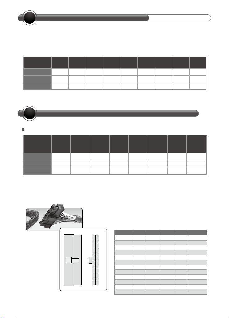
a.Main Power Connector (20+4 pin)
Support the latest ATX 12V 2.2 system motherboard
CPU
Connector
(4+4 pin)
24
23
22
21
20
19
18
17
16
15
14
13
CPU
Connector
(8 pin)
12
11
10
9
8
7
6
5
4
3
2
1
Peripheral
Connector
(4 pin)
Voltage Color Color Voltage
PWR_ON Gray 8 20 N/C N/C
+12VDC Yellow 10 22 Red +5V
+12VDC Yellow 11 23 Red +5V
SATA
(5 pin)
Floppy Disk
Connector
(4 pin)
Connector
+3.3V Orange 1 13 Orange +3.3V
+3.3V Orange 2 14 Blue +12V
COM Black 3 15 Black COM
+5V Red 4 16 Green PS_ON#
COM Black 5 17 Black COM
+5V Red 6 18 Black COM
COM Black 7 19 Black COM
+5Vsb Purple 9 21 Red +5V
+3.3V Orange 12 24 Black COM
PCI-E
Connector
(8 pin)
PCI-E
Connector
(6 pin)
5
Page 7
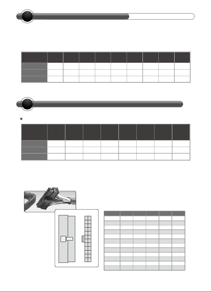
b.CPU Connector (4+4 pin)
Support both dual CPU and single CPU systems by simply combining (8 pin) or splitting (4 pin X 2)
the connectors
Color Signal Pin
Black GND 1
5
6
7
8
Black GND 2
4
Black GND 3
Black GND 4
3
Yellow +12VDC 5
Yellow +12VDC 6
2
Yellow +12VDC 7
1
Yellow +12VDC 8
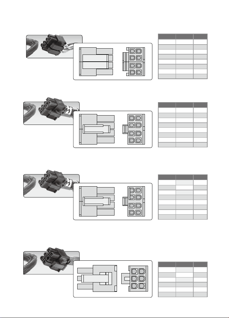
c.CPU Connector (8 pin)
Support the latest 8 pin Quad Core system motherboard
Color Signal Pin
Black COM 1
5
6
7
8
Black COM 2
4
Black COM 3
Black COM 4
3
Yellow +12VDC 5
2
Yellow +12VDC 6
Yellow +12VDC 7
1
Yellow +12VDC 8
d.PCI-E Connector (8 pin)*
Support next generation 8 pin sockets on high-end graphic cards and can support the
existing 6 pin sockets by connecting to the 8 pin to 6 pin converter.
Color Signal Pin
Yellow +12VDC 1
Yellow +12VDC 2
5
6
7
8
4
Yellow +12VDC 3
Black GND 4
3
Black GND 5
2
Black GND 6
Black GND 7
1
Black GND 8
e.PCI-E Connector (6 pin)*
Support the latest high-end graphic cards with 6 pin socket
A 6 pin & a 8 pin PCI-E connectors can be connected to the same graphic card if there are two 6 pin sockets
or both 8 pin socket and 6 pin sockets available on the card. Please refer to Section 6.2 for more information.
6 3
4 1
Color Signal Pin
Yellow 12VDC 1
Yellow 12VDC 2
Yellow 12VDC 3
Black COM 4
Black COM 5
Black COM 6
6
Page 8
f.SATA Connector (5 pin)
Support the new generation high-speed SATA devices
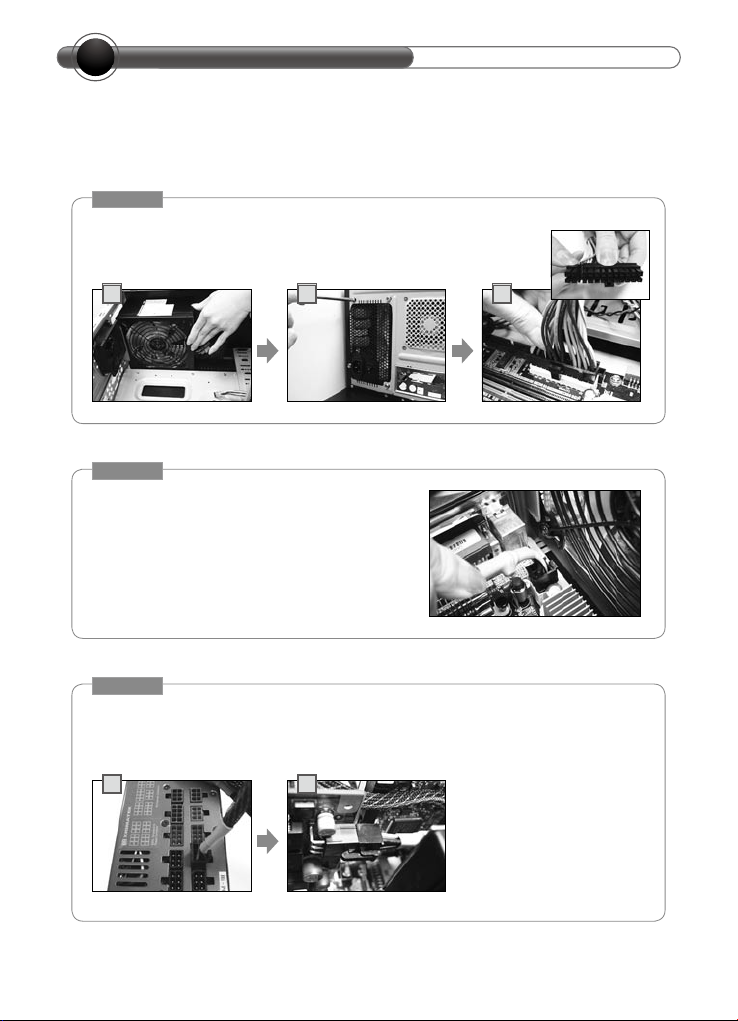
g.Peripheral Connector (4 pin)
Support IDE/SCSI (HDD/CD/DVD..etc) devices
Color Signal Pin
Yellow +12VDC 1
Black COM 2
Red +5VDC 3
Black COM 4
Orange +3.3VDC 5
1
4
Color Signal Pin
Yellow +12VDC 1
Black COM 2
Black COM 3
Red +5VDC 4
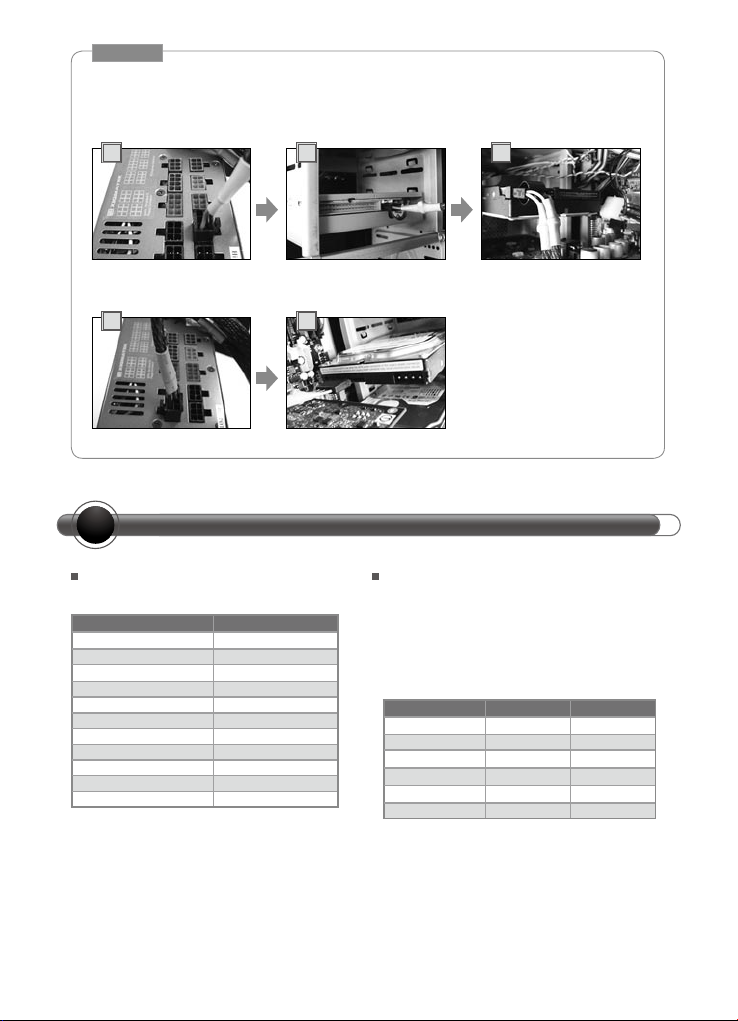
h.Floppy Disk Connector (4 pin)
Support Floppy Disk and some other additional devices
1
Color Signal Pin
Red +5VDC 1
Black COM 2
4
Black COM 3
Yellow +12VDC 4
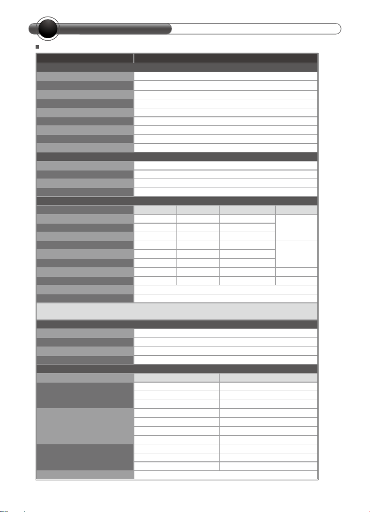
Modularized Cable Management:
Users can optimize the cables arrangement within the chassis by using only what
users need. This feather increases the airflow and reduces the overall ambient
temperature within the chassis, also improves the overall look and tidiness of the
system.
PCI-Express
Embedded Socket and
Modularized Cable
Management Design:
PCI-Express Connector
SATA, Peripheral, and
Floppy Connector
Connector
SATA,
Peripheral,
and Flopp
Connector
7
Page 9
INSTALLATION STEPS
F
To prevent electrical shocks, please disconnect the power cord from your existing
power supply unit. No Rules Power Supply has automatic voltage selector which
will automatically change to 100V-240V PSU.
STEP 1
After install the power supply unit into the chassis and then
connect the 20+4-pin main power cable to motherboard 20 pin
or 24 pin socket.
1 2 3
STEP 2
Connect the 4+4-pin/8-pin +12V auxiliary
power connector to the motherboard.
(Users can use either 4 pins or 8 pins,
depending on the motherboard. Please check
with the motherboard user’s manual.)
STEP 3
Connect the 6 pin/8 pin PCI-Express connector to your graphic card if
needed. (Notice: Before the connection, please refer to Section 6.2 for
more information.)
1
8
2
Page 10
STEP 4
Connect the 4 pin power connector to peripheral devices such as DVD-Burner,
hard drive, and etc. In addition, a user can connect the 3-pin floppy power
connector to connect the floppy drive
1 2 3
If there are S-ATA hard disk drives present, there are also Serial ATA connectors available.
1 2
+12V RAIL DISTRIBUTION & PCI-E CONNECTORS
G
+12V Rail Distribution
24 pin + 12V 12V1
4+4 pin + 12V 12V2
8 pin + 12V 12V2, 12V3
Peripheral & Floppy 12V1
S-ATA 12V1
6 pin Modular PCI-E 12V3
6 pin Modular PCI-E 12V3
6 pin Modular PCI-E 12V4
8 pin Modular PCI-E 12V3
8 pin Modular PCI-E 12V4
8 pin Modular PCI-E 12V4
NRP-HC
PCI-E Connectors and+12V
Rails Distributio
P l e a s e ca r e f ul l y r e a d th e ta b l e a n d
suggestions below when connecting the 6
pin/8 pin connectors to your graphic card(s),
especially when there are more than one PCI-E
sockets available on your card(s).
6 pin X
6 pin X
6 pin
8 pin
8 pin
8 pin X
Please be noticed that when trying to connect
more than one connector to a graphic card,
it is strongly recommended to choose the
connectors from exactly the same +12V rail.
12V3 12V4
X
X
X
9
Page 11
SPEC TableEPS
H
SPEC Table NRP-HC1001
Model
Power 1000W
Dimension 200mm(L)x150mm(W)x86mm(H)
Switches ATX Logic on-off additional power rocker switch
PFC Active PFC (PF > 0.9)
Cooling System 140mm Fan, 2300RPM±10%
Noise 16 dBA at 1300RPM
P.G. Signal 100-500 ms
Efficiency Up to 87%
Hold-up Time 16 ms
Input Voltage 100-240VAC
Input Frequency Range 50/60Hz
MTBF 120,000 hrs minimum (at 25℃)
Input Current 13A
+12V1 20A/1A +3, -3% 120mV
+3.3V 30A/0.5A +3, -3% 50mV
+12V2 20A/1A +3, -3% 120mV
+5V 30A/0.5A +3, -3% 50mV
-12V 0.8A/0A +10, -10% 120mV 9.6W
+5Vsb 3.5A/0A +3%, -5% 50mV 17.5W
Total Power 1000W
Peak Power 1100W
1. +5Vsb operate at 3.5A max load base on PS-ON mode. If PS-OFF +5Vsb only operate at 3A max load.
2. Add 0.1μF capacitors across output terminal during ripple & noise test.
Operating Temp. 10℃ to 50℃
Storage Temp. -20℃ to 70℃
Operating Humidity 20% to 90%, non-condensing
Storage Humidity 5% to 95%, non-condensing
Over Voltage Protection
Over Current Protection
Under Voltage Protection
Short Protection All output to GND
SPECIFICATION
INPUT
Output
Max/Min Regulation *1 Ripple & Noise *2 Output
Environment
Protection
DC Rail Trigger Point/Range
+3.3V trip point 4.5 Vmax
+5.0V trip point 7.0 Vmax
+12.0V trip point 15.6 Vmax
+3.3V 33A ~ 50A
+5.0V 33A ~ 50A
+12V1 & +12V2 22A ~ 35A
+12V3 & +12V4 39A ~ 55A
+3.3V trip point 2.0 Vmin
+5.0V trip point 3.3 Vmin
+12.0V trip point 8.5 Vmin
10
NRP-HC1001
500W+12V4 36A/1A +3, -3% 120mV
500W+12V3 36A/1A +3, -3% 120mV
Page 12
SPEC Table NRP-HC1201
Model
Power 1200W
Dimension 200mm(L)x150mm(W)x86mm(H)
Switches ATX Logic on-off additional power rocker switch
PFC Active PFC (PF > 0.9)
Cooling System 140mm Fan, 2300RPM±10%
Noise 16 dBA at 1300RPM
P.G. Signal 100-500 ms
Efficiency Up to 87%
Hold-up Time 16 ms
Input Voltage 100-240VAC
Input Frequency Range 50/60Hz
MTBF 120,000 hrs minimum (at 25℃)
Input Current 13A
+12V1 20A/1A +3, -3% 120mV
+3.3V 30A/0.5A +3, -3% 50mV
+12V2 20A/1A +3, -3% 120mV
+5V 30A/0.5A +3, -3% 50mV
-12V 0.8A/0A +10, -10% 120mV 9.6W
+5Vsb 3.5A/0A +3%, -5% 50mV 17.5W
Total Power 1200W
Peak Power 1300W
1. +5Vsb operate at 3.5A max load base on PS-ON mode. If PS-OFF +5Vsb only operate at 3A max load.
2. Add 0.1μF capacitors across output terminal during ripple & noise test.
Operating Temp. 10℃ to 50℃
Storage Temp. -20℃ to 70℃
Operating Humidity 20% to 90%, non-condensing
Storage Humidity 5% to 95%, non-condensing
Over Voltage Protection
Over Current Protection
Under Voltage Protection
Short Protection All output to GND
SPECIFICATION
INPUT
Output
Max/Min Regulation *1 Ripple & Noise *2 Output
Environment
Protection
DC Rail Trigger Point/Range
+3.3V trip point 4.5 Vmax
+5.0V trip point 7.0 Vmax
+12.0V trip point 15.6 Vmax
+3.3V 33A ~ 50A
+5.0V 33A ~ 50A
+12V1 & +12V2 22A ~ 35A
+12V3 & +12V4 39A ~ 55A
+3.3V trip point 2.0 Vmin
+5.0V trip point 3.3 Vmin
+12.0V trip point 8.5 Vmin
NRP-HC1201
600W+12V4 36A/1A +3, -3% 120mV
600W+12V3 36A/1A +3, -3% 120mV
11
Page 13
SPEC Table NRP-HC1501
Model
Power 1500W
Dimension 200mm(L)x150mm(W)x86mm(H)
Switches ATX Logic on-off additional power rocker switch
PFC Active PFC (PF > 0.9)
Cooling System 140mm Fan, 2300RPM±10%
Noise 16 dBA at 1300RPM
P.G. Signal 100-500 ms
Efficiency Up to 87%
Hold-up Time 10 ms
Input Voltage 230VAC
Input Frequency Range 47/63Hz
MTBF 120,000 hrs minimum (at 25℃)
Input Current 10A
+12V1 20A/1.0A +3, -3% 240mV
+3.3V 30A/0.5A +3, -3% 100mV
+12V2 20A/1.0A +3, -3% 240mV
+5V 30A/0.5A +3, -3% 100mV
-12V 0.8A/0.0A +10, -10% 240mV 9.6W
+5Vsb 3.5A/0.0A +3%, -5% 100mV 17.5W
Total Power 1500W
Peak Power 1600W
1. +5Vsb operate at 3.5A max load base on PS-ON mode. If PS-OFF +5Vsb only operate at 3A max load.
2. Add 0.1μF capacitors across output terminal during ripple & noise test.
Operating Temp. 10℃ to 50℃
Storage Temp. -20℃ to 70℃
Operating Humidity 20% to 90%, non-condensing
Storage Humidity 5% to 95%, non-condensing
Over Voltage Protection
Over Current Protection
Under Voltage Protection
Short Protection All output to GND
SPECIFICATION
INPUT
Output
Max/Min Regulation *1 Ripple & Noise *2 Output
Environment
Protection
DC Rail Trigger Point/Range
+3.3V trip point 4.5 Vmax
+5.0V trip point 7.0 Vmax
+12.0V trip point 15.6 Vmax
+3.3V 33A ~ 50A
+5.0V 33A ~ 50A
+12V1 & +12V2 22A ~ 35A
+12V3 & +12V4 42A ~ 60A
+3.3V trip point 2.0 Vmin
+5.0V trip point 3.3 Vmin
+12.0V trip point 8.5 Vmin
NRP-HC1501
750W+12V4 40A/1.0A +3, -3% 240mV
750W+12V3 40A/1.0A +3, -3% 240mV
12
Page 14
OTHER SPECIFICATION
I
Inrush Current:
55A max. when AC input 115Vac at 25℃ cold start.
110A max. when AC input 230Vac at 25℃ cold start.
Power Efficiency
80% (min.) at full load (typical) and 115Vac input
CE Requirements
1.Conducted EMI
•Meet FCC: Class B
•Meet CISPR 2 2: Class B
•Meet BSMI: Class B
2.Safety Standards
•Meet CUL (UL 60950)
•Meet TUV En60950
•Meet CB (IE C 950)
•Meet CE
3.Harmonic Meet IEC1000-3-2, Class D
TROUBLE SHOOTING
J
Condition 1:
No DC output. The fan or fans are motionless. Check:
•Is the AC inlet plug firmly plugged into the PSU inlet socket?
•Is the wall socket, extension power cord, power strip or surge protector in use, fully
functional and wall power switch turned ‘ON’?
•Is the Main Board socket (20+4 pin) plug fully and firmly inserted?
Condition 2:
The fan or fans began rotating and then stopped. The system hangs without
proceeding any further. Check:
•Are the peripheral connectors firmly plugged into accessory devices, such as the
main hard drive, CD ROM, etc?
•If a plug has been inadvertently connected in an off-set or reversed position, unplug
the AC power source, reconnect the offending connectors and then wait for 30
seconds before replug in the AC power source and try again.
Note: If the power supply is still unable to power up after following the above
instruction, please send the unit back to your dealer or retailer for after sales
service.
13
Page 15

EINFÜHRUNG
A15B
Erklärung
In unserem fortwährenden Streben nach Spitzenleistung werden wir dem XIGMATEKLogo gerecht. Wenn Sie uns etwas mitteilen möchten, rufen Sie unsere Website auf:
Http://www.xigmatek.com
Oder senden Sie uns eine E-Mail an:
support@xigmatek.com
Für Vors ch lä ge und Anmerkungen sind wir Ihnen sehr dankbar. Sie werden
umgehend Antwort von unserem Service-Team erhalten. Bevor Sie das Netzteil
installieren, sollten Sie sich das Gerät und die Anschlüsse genau ansehen und
dieses Benutzerhandbuch sorgfältig lesen. Für die Installation benötigen Sie einen
Kreuzschlitz-Schraubendreher und die Benutzerhandbücher für das PC-Gehäuse
und Motherboard.
Wenn Sie Fragen zum Inhalt des Benutzerhandbuchs haben, wenden Sie sich direkt
an XIGMATEK. Die Nicht-Beachtung der Anweisungen kann schwere Personen- und
Sachschäden zur Folge haben.
Warnungen und Vorsichtshinweise
1.Trennen Sie das Netzkabel nicht vom Stromnetz, wenn das Netzteil in Benutzung
ist. Anderenfalls können die Komponenten beschädigt werden.
2.Bewahren Sie das Netzteil nicht in Umgebungen mit hohen Temperaturen oder
hoher Luftfeuchtigkeit auf.
3.Wenn Sie das No Rules Power Cable Management -Netzteil für Testzwecke
verwenden, bei denen das Netzteil nicht im PC installiert ist, führen Sie die
folgenden Schritte aus:
•Biegen Sie eine Büroklammer gerade.
•Stellen Sie sicher, dass das Netzteil ausgeschaltet ist (“OFF”).
•Suchen Sie nun den 20+4-Pin-Motherboardanschluss des Netzteils.
•Stecken Sie das eine Ende der Büroklammer in das grüne Loch.
•Stecken Sie das andere Ende der Büroklammer in eines der schwarzen Löcher.
•Schalten Sie das Netzteil ein, um zu prüfen, ob die Netzteillüfter laufen.
4.Im Netzteil gibt es Bereiche mit Hochspannung. Das Netzteil darf nur von
autorisierten Reparaturfachleuten oder Elektrikern geöffnet werden.
5.Durch eine Nicht-Beachtung der Warn- und Vorsichtshinweise in diesem
Benutzerhandbuch verlieren alle Garantien ihre Gültigkeit.
14
Page 16

LEISTUNGSMERKMALE
Leistungsmerkmale
1.NEU!! 8-poliger PCI-E-Stecker
No Rules Power-Netzteile verfügen über drei der neuesten 8-poligen PCI-EAnschlüsse, die für die nächste Generation von NVIDIA- und ATI-Grafikkarten
erforderlich sind. Diese neu definierten 8-poligen Anschlüsse sind durch einen
Adapter (8 auf 6 Pole) abwärts kompatibel mit den bestehenden 6-poligen PCIE-Anschlüssen. Mit den drei 6-poligen/8-poligen Anschlüssen unterstützen No
Rules Power-Netzteile bis zu drei High-End-Grafikkarten.
2.Hervorragende Effizienz (bis zu 87 %)
No Rules Power-Netzteile bieten eine hervorragende Effizienz und damit einen
geringeren Stromverbrauch. Das wiederum senkt Ihre Stromkosten.
3.140-mm-Kugellagerlüfter
Der 140-mm-Kugellagerlüfter erhöht effektiv den Luftstrom im Netzteil und
verringert so die Umgebungstemperatur.
4.Extrem gute Spannungsregulierung (±3 %)
Diese Funktion ermöglicht eine genauere Lastregulierung (±3 %) als andere
Netzteile (±5 %) und erhöhen die Stabilität der Systemspannung.
5.MTBF > 120.000 Stunden (sehr zuverlässig)
120.000 Stunden MTBF (Mean Time between Failures = mittlere Betriebsdauer
zwischen Ausfällen) liegt weit über allen ATX-Spezifikationen.
6.Vier unabhängige +12V-Rails
Vier unabhängige +12V-Rails unterstützen die High-End-Grafikkarte und das PCSystem.
7.Kabelführung
Das Kabelführungssystem ermöglicht es, nicht verwendete Kabel zu entfernen,
wodurch der Luftstrom im Chassis bedeutend verbessert wird.
8.Industrielle Komponenten (Kondensatoren, Transformatoren usw.)
All e Kompo n e n ten wurd e n spezie l l für indu s t r i elle U m g e bungen un d
Extrembedingungen entwickelt.
9.Schwarze Hi-Tech-Beschichtung
Durch die spezielle schwarze Hi-Tech-Beschichtung sieht das No Rules PowerNetzteil professionell, elegant und einzigartig aus.
10.Hohe Spannungsabgabe von +5 VSB
Hohe +5VSB-Spannung (von 2 A bis 3,5 A (PS-ON-Status)) unterstützt bis zu
12 USB-Geräte. Auch bei ausgeschaltetem System können USB-Geräte durch
die gleichmäßige Abgabe von 3 A aufgeladen werden.
Page 17
ZUBEHÖR
C
No Rules Power-Netzteil
1
(mit einem 20+4-poligen Hauptsteckverbinder,
einem 4+4-poligen 12-V-Leistungssteckverbinder
und einem 8-poliger Leistungssteckverbinder)
8-poliger PCI-E-Stecker
2
6-poliger PCI-E-Stecker
3
5-poliger SATA-Stecker
4
4-poliger Peripheriestecker
5
AC-Eingangsstromkabel
6
4 Schrauben
7
Benutzerhandbuch
8
Kabelklammern
9
10
Schutzbeutel für das Netzteil
11
Kabeltasche
Ein Netzteil (mit einem 20+4-poligen
Hauptsteckverbinder, einem 4+4-poligen
+12V-Leistungssteckverbinder und einem
8-poligen Leistungssteckverbinder)
1
16
2
5
8
6 7
9
10 11
43
Page 18
PRODUKTINFORMATIONEN
D
1.EINGANGS- UND AUSGANGSSPANNUNG
2.1 EINGANGSSPANNUNG: 100 – 240 V, 47 – 63 HZ
3.1.2 AUSGANGSSPANNUNG:
Modell/
Reihe
NRP-HC1001 30A 28A 20A 20A 36A 36A 0.8A 3.5A 1000W
NRP-HC1201 30A 28A 20A 20A 36A 36A 0.8A 3.5A 1200W
NRP-HC1501 30A 30A 20A 20A 40A 40A 0.8A 3.5A 1500W
E
+3.3V +5V +12V1+12V2+12V3+12V4-12V +5Vsb
ANSCHLÜSSE UND MODULARISIERTE KABELFÜHRUNG
Gesamtleistung
Anschlüsse
Modell/
Reihe
NRP-HC1001 1 1 1 8 8 2 3 3
NRP-HC1201 1 1 1 8 8 2 3 3
NRP-HC1501 1 1 1 8 8 2 3 3
Haupt-steck-
verbinder
(20+4-polig)
a.Hauptsteckverbinder (20+4-polig)
Unterstützt das neueste ATX 12V 2.2-Motherboard
CPU-
Stecker
(4+4-polig)
CPU-
Stecker
(8-polig)
Peripherie-
stecker
(4-polig)
SATAStecker
(5-polig)
Disketten-
laufwerk-
stecker (4-polig)
PCI-EStecker
(8-polig)
PCI-EStecker
(6-polig)
24
23
22
21
20
19
18
17
16
15
14
13
Spannung Farbe Farbe Spannung
12
+3.3V Orange 1 13 Orange +3.3V
11
+3.3V Orange 2 14 Blau +12V
10
9
8
7
6
5
4
3
2
1
COM Schwarz 3 15 Schwarz COM
+5V Rot 4 16 Grün PS_ON#
COM Schwarz 5 17 Schwarz COM
+5V Rot 6 18 Schwarz COM
COM Schwarz 7 19 Schwarz COM
PWR_ON Grau 8 20 N/C N/C
+5Vsb Lila 9 21 Rot +5V
+12VDC Gelb 10 22 Rot +5V
+12VDC Gelb 11 23 Rot +5V
+3.3V Orange 12 24 Schwarz COM
17
Page 19

b.CPU-Stecker (4+4-polig)
Unterstützt Dual- und Einzel-CPUs durch Verbinden (8-polig) oder Teilen (4-polig x 2) der
Anschlüsse
Farbe Signal Pin
Schwarz GND 1
5
6
7
8
Schwarz GND 2
4
Schwarz GND 3
Schwarz GND 4
3
Gelb +12VDC 5
Gelb +12VDC 6
2
Gelb +12VDC 7
1
Gelb +12VDC 8
c.CPU-Stecker (8-polig)
Unterstützt das neueste 8-polige Quad Core-Motherboard
Farbe Signal Pin
Schwarz COM 1
5
6
7
8
Schwarz COM 2
4
Schwarz COM 3
Schwarz COM 4
3
Gelb +12VDC 5
2
Gelb +12VDC 6
Gelb +12VDC 7
1
Gelb +12VDC 8
d.PCI-E-Stecker (8-polig)*
Unterstützt die nächste Generation von 8-poligen Sockeln auf High-End- Grafikkarten und die
vorhandenen 6-poligen Sockel indem er an den Konverter (8 auf 6 Pole) angeschlossen wird.
Farbe Signal Pin
Gelb +12VDC 1
Gelb +12VDC 2
5
6
7
8
4
Gelb +12VDC 3
Schwarz GND 4
3
Schwarz GND 5
2
Schwarz GND 6
Schwarz GND 7
1
Schwarz GND 8
e.PCI-E-Stecker (6-polig)*
Unterstützt die neuesten High-End-Grafikkarten mit 6-poligen Sockeln
6-polige und 8-polige PCI-E-Anchlüsse können an die gleiche Grafikkarte angeschlossen werden, wenn auf der Karte
zwei 6-polige oder ein 6- und ein 8-poliger Sockel auf der Karte verfügbar ist. Weitere Informationen finden Sie in
Abschnitt 6.2.
6 3
4 1
Farbe Signal Pin
Gelb 12VDC 1
Gelb 12VDC 2
Gelb 12VDC 3
Schwarz COM 4
Schwarz COM 5
Schwarz COM 6
18
Page 20

f.SATA-Stecker (5-polig)
Unterstützt die neue Generation von SATA-Hochgeschwindigkeitsgeräten.
g.Peripheriestecker (4-polig)
unterstützt IDE/SCSI-Geräte (HDD/CD/DVD).
Farbe Signal Pin
Gelb +12VDC 1
Schwarz COM 2
Rot +5VDC 3
Schwarz COM 4
Orange +3.3VDC 5
1
4
Farbe Signal Pin
Gelb +12VDC 1
Schwarz COM 2
Schwarz COM 3
Rot +5VDC 4
h.Diskettenlaufwerkstecker (4-polig)
Unterstützt Diskettenlaufwerke und andere Zusatzgeräte.
1
Farbe Signal Pin
Rot +5VDC 1
Schwarz COM 2
4
Schwarz COM 3
Gelb +12VDC 4
Modularisierte Kabelführung:
Sie können im Chassis die Kabelführung so optimieren, dass Sie nur das verwenden,
was Sie benötigen. Durch dieses System wird im Chassis der Luftfluss verbessert und
die Gesamttemperatur verringert. Außerdem trägt das zur besseren Übersichtlichkeit
im Gerät bei.
Ausführung mit
eingebettetem Sockel
und modularisierter
Kabelführung:
PCIExpressStecker,SATA-, Peripherie-und
Diskettenlaufwerkstecker
PCI- Expre ssStecker
SATA-, Peripherie-und
Diskettenlaufwerkstecker
19
Page 21

INSTALLATION
F
Trennen Sie, um einen Stromschlag zu vermeiden, das Netzkabel vom vorhandenen
Netzteil vom Stromnetz. Das No Rules Power -Netzteil verfügt über einen
automatischen Spannungswähler, der automatisch auf 100 – 240 V schaltet.
SCHRITT 1
Installieren Sie das Netzteil im Chassis, und schließen Sie den
20+4-poligen Hauptsteckverbinder an den 20- oder 24-poligen
Sockel auf dem Motherboard an.
1 2 3
SCHRITT 2
S c h l ie ße n Si e de n 4 +4 -p o l i g e n/ 8poligen +12v-Hilfssteckverbinder an das
Motherboard an. (Je nach M ot he rboard
kö n n e n Sie en t w ed e r 4 o d e r 8 Pole
verwenden. Lesen Sie im Benutzerhandbuch
des Motherboards nach.)
SCHRITT 3
Schließen Sie den 6-/8-poligen PCI-Express-Stecker an die Grafikkarte an.
(Hinweis: Lesen Sie vor dem Anschließen Abschnitt 6.2 durch.)
1
20
2
Page 22

SCHRITT 4
Schließen Sie den 4-poligen Leistungssteckverbinder an Peripheriegeräte
wie DVD-Brenner oder Festplatten an. Zusätzlich können Sie den 3-poligen
Diskettenlaufwerkstecker an das Diskettenlaufwerk anschließen.
1 2 3
Wenn S-ATA-Festplatten vorhanden sind, sind auch Serial-ATA-Anschlüsse vorhanden.
1 2
+12V-RAIL-BELEGUNG UND PCI-E-STECKER
G
+12V-Rail-Belegung PCI-E-Stecker und
+12V-Rail-Belegung
24-polig + 12 V 12V1
4+4-polig + 12 V 12V2
8-polig + 12 V 12V2, 12V3
Peripheriegerät und
Diskettenlaufwerk
S-ATA 12V1
6-poliger modularer PCI-E 12V3
6-poliger modularer PCI-E 12V3
6-poliger modularer PCI-E 12V4
8-poliger modularer PCI-E 12V3
8-poliger modularer PCI-E 12V4
8-poliger modularer PCI-E 12V4
NRP-HC
12V1
Beach ten Sie die folgen de Tabe lle u nd die
Empf eh lu ng en, we nn Sie di e 6-/ 8- poligen
Ste cker an die Grafi kka rte(n) ansc hließen,
insbesondere wenn sich auf der Karte(n) mehr
als ein PCI-E-Sockel befindet.
6-polig X
6-polig X
6-polig
8-polig
8-polig
8-polig X
Wenn S ie mehr als einen Stec ker an eine
Gr af ik ka rt e an schli eß en , wi rd empfohl en ,
nur die Anschlüsse derselben +12V-Rail zu
verwenden.
12V3 12V4
X
X
X
21
Page 23

Technische Daten EPS
H
Technische Daten NRP-HC1001
Modell
Leistung 1000W
Abmessungen 200 mm x 150 mm x 86 mm (H) (L x B x H)
PFC (Leistungsfaktor-korrektur) Aktive PFC (PF > 0,9)
Schalter zusätzlicher ATX Logic-Ein/Aus-Wippschalter
Kühlsystem 140-mm-Lüfter, 2300 U/Min. ±10 %
Geräuschpegel 16 dBA bei 1300 U/Min.
PG-Signal 100-500 ms
Effizienz bis 87 %
Überbrückungszeit 16 ms
Eingangsspannung 100-240VAC
Eingangsfrequenz-bereich 50/60Hz
MTBF 120.000 Std. mindestens (bei 25 °C)
Eingangsstrom 13A
+12V1 20 A/1,0 A +3, -3 % 120mV
+3.3V 30A/0.5A +3, -3 % 50mV
+12V2 20A/1.0A +3, -3 % 120mV
+5V 30A/0.5A +3, -3 % 50mV
-12V 0.8A/0.0A +10, -10 % 120mV 9.6W
+5Vsb 3.5A/0.0A + 3 %, -5 % 50mV 17.5W
Gesamtleistung 1000W
Spitzenleistung 1100W
1. +5Vsb nur bei 3,5 A max. Last im PS-ON-Modus. Wenn PS-OFF +5Vsb nur bei 3 A Maximallast arbeitet.
2. Verwenden Sie während des Brumm- und Rauschtests 0.1μF-Kondensatoren am Ausgang.
Temperatur (Betrieb) 10 bis 50 °C
Temperatur (Lagerung) -20 bis 70 °C
Luftfeuchtigkeit (Betrieb) 20 bis 90 %, nicht-kondensierend
Luftfeuchtigkeit (Lagerung) 5 bis 95 %, nicht-kondensierend
Überspannungsschutz
Überstromschutz
Unterspannungsschutz
Kurzschlussschutz Gesamter Ausgang an Masse
TECHNISCHE DATEN
EINGANG
AUSGANG
Max./Min. Vorgabe *1
Umgebungsbedingungen
Schutz
DC-Rail Triggerpunkt/Bereich
Trippunkt +3,3 V 4,5 V max.
Trippunkt +5,0 V 7,0 V max.
Trippunkt +12,0 V 15,6 V max.
+3.3V 33 – 50 A
+5.0V 33 – 50 A
+12 V1 und +12 V2 22 – 35 A
+12 V3 und +12 V4 39 – 55 A
Trippunkt +3,3V 2,0 V min.
Trippunkt +5,0 V 3,3 V min.
Trippunkt +12,0 V 8,5 V min.
22
NRP-HC1001
Brummen und Rauschen *2
Ausgang
500W+12V4 36A/1.0A +3, -3 % 120mV
500W+12V3 36A/1.0A +3, -3 % 120mV
Page 24

Technische Daten NRP-HC1201
Modell
Leistung 1200W
Abmessungen 200 mm x 150 mm x 86 mm (H) (L x B x H)
PFC (Leistungsfaktor-korrektur) Aktive PFC (PF > 0,9)
Schalter zusätzlicher ATX Logic-Ein/Aus-Wippschalter
Kühlsystem 140-mm-Lüfter, 2300 U/Min. ±10 %
Geräuschpegel 16 dBA bei 1300 U/Min.
PG-Signal 100-500 ms
Effizienz bis 87 %
Überbrückungszeit 16 ms
Eingangsspannung 100-240VAC
Eingangsfrequenz-bereich 50/60Hz
MTBF 120.000 Std. mindestens (bei 25 °C)
Eingangsstrom 13A
+12V1 20 A/1,0 A +3, -3 % 120mV
+3.3V 30A/0.5A +3, -3 % 50mV
+12V2 20A/1.0A +3, -3 % 120mV
+5V 30A/0.5A +3, -3 % 50mV
-12V 0.8A/0.0A +10, -10 % 120mV 9.6W
+5Vsb 3.5A/0.0A + 3 %, -5 % 50mV 17.5W
Total Power 1200W
Peak Power 1300W
1. +5Vsb nur bei 3,5 A max. Last im PS-ON-Modus. Wenn PS-OFF +5Vsb nur bei 3 A Maximallast arbeitet.
2. Verwenden Sie während des Brumm- und Rauschtests 0.1μF-Kondensatoren am Ausgang.
Temperatur (Betrieb) 10 bis 50 °C
Temperatur (Lagerung) -20 bis 70 °C
Luftfeuchtigkeit (Betrieb) 20 bis 90 %, nicht-kondensierend
Luftfeuchtigkeit (Lagerung) 5 bis 95 %, nicht-kondensierend
Überspannungsschutz
Überstromschutz
Unterspannungsschutz
Kurzschlussschutz Gesamter Ausgang an Masse
TECHNISCHE DATEN
EINGANG
AUSGANG
Max./Min. Vorgabe *1
Umgebungsbedingungen
Schutz
DC-Rail Triggerpunkt/Bereich
Trippunkt +3,3 V 4,5 V max.
Trippunkt +5,0 V 7,0 V max.
Trippunkt +12,0 V 15,6 V max.
+3.3V 33 – 50 A
+5.0V 33 – 50 A
+12 V1 und +12 V2 22 – 35 A
+12 V3 und +12 V4 39 – 55 A
Trippunkt +3,3V 2,0 V min.
Trippunkt +5,0 V 3,3 V min.
Trippunkt +12,0 V 8,5 V min.
NRP-HC1201
Brummen und Rauschen *2
Ausgang
600W+12V4 36A/1.0A +3, -3 % 120mV
600W+12V3 36A/1.0A +3, -3 % 120mV
23
Page 25

SPEC Table NRP-HC1501
Modell
Leistung 1500W
Abmessungen 200 mm x 150 mm x 86 mm (H) (L x B x H)
PFC (Leistungsfaktor-korrektur) Aktive PFC (PF > 0,9)
Schalter zusätzlicher ATX Logic-Ein/Aus-Wippschalter
Kühlsystem 140-mm-Lüfter, 2300 U/Min. ±10 %
Geräuschpegel 16 dBA bei 1300 U/Min.
PG-Signal 100-500 ms
Effizienz bis 87 %
Überbrückungszeit 16 ms
Eingangsspannung 230VAC
Eingangsfrequenz-bereich 47/63Hz
MTBF 120.000 Std. mindestens (bei 25 °C)
Eingangsstrom 13A
+12V1 20 A/1,0 A +3, -3 % 240mV
+3.3V 30A/0.5A +3, -3 % 100mV
+12V2 20A/1.0A +3, -3 % 240mV
+5V 30A/0.5A +3, -3 % 100mV
-12V 0.8A/0.0A +10, -10 % 240mV 9.6W
+5Vsb 3.5A/0.0A + 3 %, -5 % 100mV 17.5W
Gesamtleistung 1500W
Spitzenleistung 1600W
1. +5Vsb nur bei 3,5 A max. Last im PS-ON-Modus. Wenn PS-OFF +5Vsb nur bei 3 A Maximallast arbeitet.
2. Verwenden Sie während des Brumm- und Rauschtests 0.1μF-Kondensatoren am Ausgang.
Temperatur (Betrieb) 10℃ to 50℃
Temperatur (Lagerung) -20℃ to 70℃
Luftfeuchtigkeit (Betrieb) 20% to 90%, non-condensing
Luftfeuchtigkeit (Lagerung) 5% to 95%, non-condensing
Überspannungsschutz
Überstromschutz
Unterspannungsschutz
Kurzschlussschutz Gesamter Ausgang an Masse
TECHNISCHE DATEN
EINGANG
AUSGANG
Max./Min. Vorgabe *1
Umgebungsbedingungen
Schutz
DC-Rail Triggerpunkt/Bereich
Trippunkt +3,3 V 4,5 V max.
Trippunkt +5,0 V 7,0 V max.
Trippunkt +12,0 V 15,6 V max.
+3.3V 33 – 50 A
+5.0V 33 – 50 A
+12 V1 und +12 V2 22 – 35 A
+12 V3 und +12 V4 42 – 60 A
Trippunkt +3,3V 2,0 V min.
Trippunkt +5,0 V 3,3 V min.
Trippunkt +12,0 V 8,5 V min.
NRP-HC1501
Brummen und Rauschen *2
Ausgang
750W+12V4 36A/1.0A +3, -3 % 240mV
750W+12V3 36A/1.0A +3, -3 % 240mV
24
Page 26

SONSTIGE TECHNISCHE DATEN
I
Einschaltstrom:
55 A max. bei Kaltstart mit AC-Eingang von 115 VAC bei 25 °C.
110 A max. bei Kaltstart mit AC-Eingang von 230 VAC bei 25 °C.
Stromeffizienz
80 % (min.) bei voller Last (typisch) und 115 VAC
Zertifizierungen
1.Durchgeführte EMI
•Entspricht FCC: Klasse B
•Entspricht CISPR 2 2: Klasse B
•Entspricht BSMI: Klasse B
2.Sicherheitsstandards
•Entspricht CUL (UL 60950)
•Entspricht TÜV En60950
•Entspricht CB (IE C 950)
•Entspricht CE
3.Entspricht IEC1000-3-2, Klasse D
FEHLERBEHEBUNG
J
Zustand 1:
Keine DC-Ausgabe. Der oder die Lüfter bewegen sich nicht. Prüfen Sie:
•Ist der AC-Eingangsstecker richtig an den Netzteilanschluss angeschlossen
•Funktionieren die Netzsteckdose, das Verlängerungskabel, die Steckerleiste oder der
Spannungsschutz richtig, und ist das Gerät eingeschaltet (‘ON’)?
•Ist der Motherboard-Stecker (20+4-polig) richtig angeschlossen?
Zustand 2:
Der oder die Lüfter haben sich gedreht, aber laufen jetzt nicht mehr. Das System ist
hängen geblieben. Prüfen Sie:
•Sind die Peripherieanschlüsse richtig an die Geräte wie Festplatte, CD-ROM-
Laufwerk usw. angeschlossen?
•Wenn ein Stecker falsch herum eingesteckt wurde, trennen Sie das Gerät vom
Stromnetz. Drehen Sie den entsprechenden Stecker um, und warten Sie 30
Sekunden, bis Sie das Gerät wieder an das Stromnetz anschließen und einschalten.
Hinweis: Wenn das Netzteil weiterhin nicht funktioniert, wenden Sie sich zur
Reparatur an Ihren Händler.
25
Page 27

はじめに
A
声明
私たちは XIGMATEK ロゴの誓約を貫き、永遠に最高級を追求することを誓います。ご意
見、ご感想などは弊社ウェブサイトにて受け付けております。
Http://www.xigmatek.com
またはメールにてご連絡ください。
support@xigmatek.com
ユーザーの皆様のご意見、ご感想に感謝いたします。弊社カスタマーサービスチームがユ
ーザーの皆様に迅速な対応をさせていただきます。電源装置をインストールする前に、ま
ず本機およびコネクタに関する理解を深め、本書の内容をよくお読みください。インスト
ールにはプラスドライバー、PC ケースの取扱説明書、マザーボードの取扱説明書などが必
要となる場合があります。
本書に関するご質問は、XIGMATEK に直接お問い合わせください。本書の指示に従わず操
作すると、けがや PC 部品の故障を招く恐れがありますのでご注意ください。
警告と注意事項
1.電源がオンになっているときは、部品を傷つける恐れがありますので、AC アダプタコー
トを引っ張らないでください。
2.電源装置を高温多湿の場所に保管しないでください。
3.電源装置が部品と一緒に PC にインストールされていないテスト状況において、No Rules
Power ケーブル管理電源装置をお使いの場合、次の手順に従ってください。
ペーパークリップを使用します。まずクリップをまっすぐに伸ばしてください。
•
電源装置が “オフ” になっていることを確認してください。
•
電源装置で20+4 ピンのマザーボードコネクタを確認してください。
•
ペーパークリップの片方を緑色のワイヤーホールに差し込みます。
•
ペーパークリップのもう片方を空いているワイヤーホールに差し込みます。
•
PSU をオンにし、電源装置のファンが回転するかどうか確認します。
•
4.源装置には高電圧が流れています。資格のある修理技師や電気業者以外は、電源装置の
ケースを開けないでください
5.本書に記載された警告や注意事項を守らない場合、すべての保証および保証契約は無効
となります。
。
26
Page 28

製品の特徴
B
製品の特徴
1.最新の8ピン PCI-E コネクタです。
No Rules Power 電源装置には、次世代の NVIDIA および ATI グラフィックカードに必要
な最新型8ピン PCI-E コネクタが3つ搭載されています。新たに定義されたこれらの8ピン
コネクタは、8ピン-6ピンの変換機を使用することにより、既存の6ピン PCI-E コネクタ
との下位互換性も確保しています。このため、3つの6ピン/8ピンコネクタを備えた No
Rules Power 電源装置は、最大3つの最新鋭グラフィックカードに対応することができま
す。
2.最高の効率 (最大87% 向上)
No Rules Power 電源装置は最高の効率を提供しながら、電機消耗率を抑えます。このた
め、ユーザーの皆様の電気代を抑えることができます。
3.40mm ボールベアリングファン
140mm ボールベアリングファンは効果的に PSU の通気性を高め、周辺温度を下げるこ
とができます。
4.優れた電圧制御 (±3%)
この機能は、通常の電源装置 (±5%) よりも優れた負荷制御 (±3%) を提供するため、シ
ステムに安定した電圧を送ることができます。
5.MTBF > 120,000 時間 (高い信頼性)
120,000 時間の MTBF (平均故障間隔) は、すべての ATX 仕様を上回ります。
6.4つの独立した +12V レール
高性能グラフィックカードや PC システムをサポートするため、4つの独立した +12V レ
ールを提供しています。
7.ケーブル管理
ケーブル管理機能により、不要なケーブルを排除したり、シャーシのエアフローを大幅
に向上させることができます。
8.工業レベルの部品 (コンデンサ、トランスなど)
すべての部品は工業レベルで設計されており、高度な環境にも耐えることができます。
9.ハイテク・ブラックコーティング
特殊なハイテク・ブラックコーティングにより、No Rules Power 電源装置は極めて専門
的でエレガントです。
10.+5VSB の高出力
内蔵の +5VSB 高電圧 (2A~3.5A (PS-ON ステータス)) は最大12台の USB デバイスを
サポートできます。また、システムの電源がオフの状態でも、USB デバイスを3Aの継
続出力で充電することができます。
27
Page 29

パッケージ内容
C
1
No Rules Power 電源装置
(20+4ピン電源コネクタx1、4+4ピン+12V 電源
コネクタx1、8ピン電源コネクタx1)
8ピン PCI-E コネクタ
2
ピン PCI-E コネクタ
3
5ピン SATA コネクタ
4
4ピン周辺コネクタ
5
AC 入力電源コード
6
7
4つの取り付けネジ
8
ユーザーズマニュアルCable ties
9
ケーブル留め具Cable kits bag
10
電源ダストバッグ
11
ケーブルキットバッグ
1
電源 装 置x1 (20 + 4ピン 主 電源コ ネクタ
x1、4+4ピン+12Vx1) 電源コネクタ、お
よび8ピン電源コネクタ)
28
2
5
8
6 7
9
10 11
43
Page 30

製品情報
D
1.入出力電圧
2.1入力電圧:100V~240V 47HZ~63HZ
3.1.2出力電圧:
モデル/セット
+3.3V +5V +12V1+12V2+12V3+12V4-12V +5Vsb
NRP-HC1001 30A 28A 20A 20A 36A 36A 0.8A 3.5A 1000W
NRP-HC1201 30A 28A 20A 20A 36A 36A 0.8A 3.5A 1200W
NRP-HC1501 30A 30A 20A 20A 40A 40A 0.8A 3.5A 1500W
コネクタおよびモジュール化ケーブルの管理
E
合計
電圧
コネクタ
モデル/セット
主電源
コネクタ
(20+4ピン)
CPU
コネクタ
(4+4ピン)
CPU
コネクタ
(8ピン)
周辺コ
ネクタ
(4ピン)
NRP-HC1001 1 1 1 8 8 2 3 3
NRP-HC1201 1 1 1 8 8 2 3 3
NRP-HC1501 1 1 1 8 8 2 3 3
a.主電源コネクタ (20+4ピン)
最新の ATX 12V 2.2 システムマザーボードに対応
SATAコ
ネクタ
(5ピン)
フロッピー
ディスクコ
ネクタ
(4ピン)
PCI-E
コネクタ
(8ピン)
PCI-E
コネクタ
(6ピン)
24
23
22
21
20
19
18
17
16
15
14
13
電圧 カラー カラー 電圧
12
11
10
9
8
7
6
5
4
3
2
1
+3.3V
+3.3V
COM
+5V
COM
+5V
COM
PWR_ON
+5Vsb
+12VDC
+12VDC
+3.3V
オレンジ
オレンジ
ブラック
レッド
ブラック
レッド
ブラック
グレイ
パープル
イエロー
イエロー
オレンジ
1 13
2 14
3 15
4 16
5 17
6 18
7 19
8 20
9 21
10 22
11 23
12 24
オレンジ
ブルー
ブラック
グリーン
ブラック
ブラック
ブラック
N/C
レッド
レッド
レッド
ブラック
+3.3V
+12V
COM
PS_ON#
COM
COM
COM
N/C
+5V
+5V
+5V
COM
29
Page 31

b.CPU コネクタ (4+4ピン)
コネクタを組み合わせたり (8ピン)、または分割したり (4ピンx2) することで、デュアル
CPU とシングル CPU システムの両方に対応しています。
カラー シングル ピン
ブラック
5
6
7
8
ブラック
4
ブラック
ブラック
3
イエロー
2
イエロー
イエロー
1
イエロー
GND 1
GND 2
GND 3
GND 4
+12VDC 5
+12VDC 6
+12VDC 7
+12VDC 8
c.CPU コネクタ (8ピン)
最新の8ピンのクアドコアマザーボードに対応
カラー シングル ピン
ブラック
5
6
7
8
ブラック
4
ブラック
ブラック
3
イエロー
2
イエロー
イエロー
1
イエロー
COM 1
COM 2
COM 3
COM 4
+12VDC 5
+12VDC 6
+12VDC 7
+12VDC 8
d.PCI-Eコネクタ (8ピン)*
高性能グラフィックカードに搭載された次世代の8ピンソケットに対応しながら、8ピン-6ピ
ン変換機を使い、既存の6ピンソケットにも対応しています。
カラー シングル ピン
イエロー
+12VDC 1
イエロー
イエロー
ブラック
ブラック
ブラック
ブラック
ブラック
+12VDC 2
+12VDC 3
GND 4
GND 5
GND 6
GND 7
GND 8
5
6
7
8
4
3
2
1
e.PCI-Eコネクタ (6ピン)*
6ピンソケットを搭載した最新の高度グラフィックカードに対応しています。
1つのカードに2つの6ピンソケットがある場合、または8ピンソケットと6ピンソケットの両方がある場合、6ピンと8ピンの PCI-E コ
ネクタを同じグラフィックカードに接続することができます。詳しくは第6.2項をご覧ください。
30
6 3
4 1
カラー シングル ピン
イエロー
12VDC 1
イエロー
12VDC 2
イエロー
12VDC 3
ブラック
ブラック
ブラック
COM 4
COM 5
COM 6
Page 32

f.SATAコネクタ (5ピン)
新世代の高速 SATA デバイスに対応しています。
g.周辺コネクタ (4ピン)
は IDE/SCSI (HDD/CD/DVD など) デバイスに対応しています。
カラー シングル ピン
イエロー
+12VDC 1
ブラック
ブラック
オレンジ
レッド
COM 2
+5VDC 3
COM 4
+3.3VDC 5
1
カラー シングル ピン
イエロー
+12VDC 1
ブラック
4
ブラック
レッド
COM 2
COM 3
+5VDC 4
h.フロッピーディスクコネクタ (4ピン)
フロッピーディスクおよびその他の追加デバイスに対応しています。
1
カラー シングル ピン
レッド
+5VDC 1
ブラック
4
ブラック
イエロー
COM 2
COM 3
+12VDC 4
モジュール化ケーブル管理
必要なものだけを使い、シャーシ内のケーブル配置を最適化することができます。この機能に
より、通気性を改善するとともに、シャーシ内の温度を下げることができます。また、外観を
改善し、システムをすっきり見せることができます。
PCI-Express
内 蔵 ソ ケ ッ ト と モ ジ ュ
ー ル 化 ケ ー ブ ル 管 理 設
計: PCI-Express コネクタ
SA TA 、周 辺コネ クタ 、
フロッピーコネクタ
コネクタ
SATA、
周辺、フロッ
ピーコネクタ
31
Page 33

インストール手順
F
感電を防ぐため、既存の電源装置から電源コードを取り外してください。No Rules Power
電源装置には自動電圧選択機能が搭載されているため、100V-240V PSU を自動的に変更す
ることができます
STEP 1
電源装置をシャーシにインストールした後、20+4ピン主電源ケーブ
ルをマザーボードの20ピンまたは24ピンソケットに接続します。
1 2 3
STEP 2
4+4ピン/8ピン +12v 補助電源コネクタをマザ
ーボ ードに 接続 します 。(マ ザー ボ ード によっ
て、 4 ピン ま たは8 ピンを 使 用で き ます。 マザ
ーボードのユーザーズマニュアルをご覧くださ
い。)
STEP 3
必要に応じて、6ピン/8ピン PCE-Express コネクタをグラフィックカードに接続
します。(メモ:接続の前に、第6.2項をご覧ください。)
1
32
2
Page 34

STEP 4
4ピン電源コネクタを DVD レコーダ、ハードドライブなどの周辺デバイスに接続しま
す。また、3ピンフロッピー電源コネクタを使ってフロッピードライブを接続すること
もできます。
1 2 3
S-ATA ハードディスクドライブがある場合、シリアル
ATA コネクタもご利用になれます。
1 2
+12V レール分配と PCI-E コネクタ
G
+12V レール配分 PCI-E コネクタと+12V レール配分
6ピン /8ピンコネクタ をグラフィックカ ー
24ピン + 12V
4+4ピン + 12V
8ピン + 12V
周辺およびフロッピー
S-ATA
6ピンモジュラー PCI-E
6ピンモジュラー PCI-E
6ピンモジュラー PCI-E
8ピンモジュラー PCI-E
8ピンモジュラー PCI-E
8ピンモジュラー PCI-E
NRP-HC
12V1
12V2
12V2, 12V3
12V1
12V1
12V3
12V3
12V4
12V3
12V4
12V4
ドに接続する際は、以下の表及び注意事項
をよくお読みください。特にカードに複数
の PCI-E ソケットがある場合はご注意くだ
さい。
6ピン
6ピン
6ピン
8ピン
8ピン
8ピン
複数のコネクタを1つのグラフィックカードに接続
する場合は、全く同じ +12V レールからコネクタ
を選択することを強く推奨します。
12V3 12V4
X
X
X
X
X
X
33
Page 35

仕様表 EPS
H
仕様表 NRP-HC1001
モデル
電力
寸法
スイッチ
PFC
冷却システム
ノイズ
P.G. シングル
効能
保留時間
入力電圧
入力周波数範囲
MTBF
入力電流
+12V1
+12V4
+3.3V
+12V2
+12V3
+5V
-12V
+5Vsb
合計電圧
ピーク電圧
1. PS-ON モードで +5Vsb @ 3.5A の最大負荷PS-OFF +5Vsb が @ 3A 最大負荷で動作した場合。
2. リップル&ノイズテスト時に0.1μF コンデンサを出力端子に追加します。
動作温度
保管温度
動作湿度
保存湿度
過電圧保護
過電流保護
電圧保護下
ショート保護
仕様
ATX ロジック オン/オフ追加電源ロッカースイッチ
入力
出力
最大/最小 規定 *1 リップル&ノイズ *2 出力
20A/1A +3, -3% 120mV
36A/1A +3, -3% 120mV
30A/0.5A +3, -3% 50mV
20A/1A +3, -3% 120mV
36A/1A +3, -3% 120mV
30A/0.5A +3, -3% 50mV
0.8A/0A +10, -10% 120mV 9.6W
3.5A/0A +3%, -5% 50mV 17.5W
環境
保護
RC レール トリガポイント/範囲
+3.3V トリップポイント 最大4.5 V
+5.0V トリップポイント 最大7.0 V
+12.0V トリップポイント 最大15.6 V
+3.3V 33A ~ 50A
+5.0V 33A ~ 50A
+12V1 & +12V2 22A ~ 35A
+12V3 & +12V4 39A ~ 55A
+3.3V トリップポイント 最小2.0 V
+5.0V トリップポイント 最小3.3 V
+12.0V トリップポイント 最小8.5 V
34
NRP-HC1001
1000W
200mm(L)x150mm(W)x86mm(H)
アクティブ PFC (PF > 0.9)
140mm ファン、2300RPM±10%
16 dBA @ 1300RPM
100-500 ms
最大87%
16 ms
100-240VAC
50/60Hz
最低 120,000 時間 (@ 25℃)
1000W
1100W
10℃ to 50℃
-20℃ to 70℃
20% ~ 90%、結露なし
5% ~ 95%、結露なし
すべて GND に出力
13A
500W
500W
Page 36

仕様表 NRP-HC1201
モデル
電力
寸法
スイッチ
PFC
冷却システム
ノイズ
P.G. シングル
効能
保留時間
入力電圧
入力周波数範囲
MTBF
入力電流
+12V1
+12V4
+3.3V
+12V2
+12V3
+5V
-12V
+5Vsb
Total Power
Peak Power
1. PS-ON モードで +5Vsb @ 3.5A の最大負荷PS-OFF +5Vsb が @ 3A 最大負荷で動作した場合。
2. リップル&ノイズテスト時に0.1μF コンデンサを出力端子に追加します。
動作温度
保管温度
動作湿度
保存湿度
過電圧保護
過電流保護
電圧保護下
ショート保護
仕様
ATX ロジック オン/オフ追加電源ロッカースイッチ
入力
出力
最大/最小 規定 *1 リップル&ノイズ *2 出力
20A/1A +3, -3% 120mV
36A/1A +3, -3% 120mV
30A/0.5A +3, -3% 50mV
20A/1A +3, -3% 120mV
36A/1A +3, -3% 120mV
30A/0.5A +3, -3% 50mV
0.8A/0A +10, -10% 120mV 9.6W
3.5A/0A +3%, -5% 50mV 17.5W
環境
保護
RC レール トリガポイント/範囲
+3.3V トリップポイント 最大4.5 V
+5.0V トリップポイント 最大7.0 V
+12.0V トリップポイント 最大15.6 V
+3.3V 33A ~ 50A
+5.0V 33A ~ 50A
+12V1 & +12V2 22A ~ 35A
+12V3 & +12V4 39A ~ 55A
+3.3V トリップポイント 最小2.0 V
+5.0V トリップポイント 最小3.3 V
+12.0V トリップポイント 最小8.5 V
NRP-HC1201
1200W
200mm(L)x150mm(W)x86mm(H)
アクティブ PFC (PF > 0.9)
140mm ファン、2300RPM±10%
16 dBA at 1300RPM
100-500 ms
最大87%
16 ms
100-240VAC
50/60Hz
最低 120,000 時間 (@ 25℃)
13A
1200W
1300W
10℃ to 50℃
-20℃ to 70℃
20% ~ 90%、結露なし
5% ~ 95%、結露なし
すべて GND に出力
600W
600W
35
Page 37

仕様表 NRP-HC1501
モデル
電力
寸法
スイッチ
PFC
冷却システム
ノイズ
P.G. シングル
効能
保留時間
入力電圧
入力周波数範囲
MTBF
入力電流
+12V1 20A/1.0A +3, -3% 240mV
+3.3V 30A/0.5A +3, -3% 100mV
+12V2 20A/1.0A +3, -3% 240mV
+5V 30A/0.5A +3, -3% 100mV
-12V 0.8A/0.0A +10, -10% 240mV 9.6W
+5Vsb 3.5A/0.0A +3%, -5% 100mV 17.5W
合計電圧
ピーク電圧
1. PS-ON モードで +5Vsb @ 3.5A の最大負荷PS-OFF +5Vsb が @ 3A 最大負荷で動作した場合。
2. リップル&ノイズテスト時に0.1μF コンデンサを出力端子に追加します。
動作温度
保管温度
動作湿度
保存湿度
過電圧保護
過電流保護
電圧保護下
ショート保護
仕様
ATX ロジック オン/オフ追加電源ロッカースイッチ
入力
出力
最大/最小 規定 *1 リップル&ノイズ *2 出力
環境
保護
RC レール トリガポイント/範囲
+3.3V トリップポイント 最大4.5 V
+5.0V トリップポイント 最大7.0 V
+12.0V トリップポイント 最大15.6 V
+3.3V 33A ~ 50A
+5.0V 33A ~ 50A
+12V1 & +12V2 22A ~ 35A
+12V3 & +12V4 42A ~ 60A
+3.3V トリップポイント 最小2.0 V
+5.0V トリップポイント 最小3.3 V
+12.0V トリップポイント 最小8.5 V
NRP-HC1501
1500W
200mm(L)x150mm(W)x86mm(H)
アクティブ PFC (PF > 0.9)
140mm ファン、2300RPM±10%
16 dBA at 1300RPM
100-500 ms
最大87%
10 ms
230VAC
47/63Hz
最低 120,000 時間 (@ 25℃)
10A
1500W
1600W
10℃ to 50℃
-20℃ to 70℃
20% ~ 90%、結露なし
5% ~ 95%、結露なし
すべて GND に出力
750W+12V4 40A/1.0A +3, -3% 240mV
750W+12V3 40A/1.0A +3, -3% 240mV
36
Page 38

その他の仕様
I
入力電流:
AC 入力115Vac @ 25℃のコールドスタートの場合、最大50A。
AC 入力230Vac @ 25℃のコールドスタートの場合、最大110A。
電力効率
全負荷時、115Vac 入力で 80% (最小)。
CE 要件
1.実施 EMI
•FCC クラス B 準拠
•CISPR 2 2 クラス B 準拠
•BSMI クラス B 準拠
2.安全規定
•CUL (UL 60950) 準拠
TUV En60950 準拠
•
CB (IE C 950) 準拠
•
•CE 準拠
3.調波 IEC1000-3-2 クラス D 準拠
トラブルシューティング
J
状況 1:
DC 出力がない。ファンが動かない。確認事項:
•AC 入力プラグはしっかりと PSU ソケット差込口に差し込まれていますか?
•壁のコンセント、延長コード、ケーブルタップ、サージ保護などは正常に機能しており、壁
の電源は “オン” の状態にありますか?
•メインボードソケット (20+4ピン) プラグは完全に差し込まれていますか?
状況 2:
ファンが回転するが、すぐに止まってしまう。操作中にシステムがフリーズする。確認事項:
•周辺コネクタは、ハードドライブや CD-ROM などの機器にしっかりと接続されていますか?
•プラグがうっかり消えていたり、逆の位置で差し込まれている場合は、AC 電源を取り外
し、再度問題のあるコネクタに接続してみてください。AC 電源をもう一度差し込む前に、
30秒間お待ちください。
メモ:上記の点検を行っても、電源装置が正常に作動しない場合は、本体をお買い上げ店また
は修理店にお持ちになり、アフターサービスを受けてください。
37
Page 39

INTRODUCCIÓN
A39B
Comunicado
Cumplimos con la promesa del logotipo XIGMATEK en nuestra incesante búsqueda de
la excelencia. Para cualquier sugerencia o comentario, entre en nuestra página web:
Http://www.xigmatek.com
o envíe un correo electrónico a:
support@xigmatek.com
Apreciamos sus comentarios y recibirá respuesta en breve de nuestro servicio
de atención al cliente. Tómese su tiempo para familiarizarse con la fuente de
alimentación, sus conectores y el contenido de este manual antes de continuar con
la instalación de la unidad de alimentación. Necesitará un destornillador de estrella
Philips, tal vez el manual de la torre de su PC y más probablemente el manual de su
placa base.
Si tiene alguna pregunta referente al contenido del manual, contacte con XIGMATEK
directamente. Si no sigue los procedimientos apropiados podría provocarse lesiones
corporales serias o daños en los componentes del PC.
Avisos y precauciones
1.No tire del cable de alimentación AC cuando esté usando la fuente de
alimentación o dañará los componentes.
2.No guarde la fuente de alimentación en un lugar con mucha humedad y altas
temperaturas.
3.Si utiliza la fuente de alimentación No Rules Power Cable management en
condiciones de prueba donde la fuente de alimentación no está instalada
en un PC con sus componentes, siga estos pasos:
•Tome un clip de papel y despliéguelo.
•Asegúrese de que la fuente de alimentación esté en la posición “OFF”.
•Localice el conector de la placa base 20+4 contactos en la fuente de
alimentación.
•Conecte un extremo del clip de papel en el agujero del cable verde.
•Conecte el otro extremo del clip de papel en cualquier agujero de cable negro.
•Encienda la PSU para ver si el/los ventilador(es) se enciende(n).
4.En la fuente de alimentación existe alto voltaje. No abra la carcasa de la fuente
de alimentación a menos que sea un técnico autorizado o un electricista.
5.Todas las garantías y certificados de garantía quedarán anulados si no cumple
con cualquiera de los avisos y precauciones cubiertos en este manual.
38
Page 40

CARACTERÍSTICAS DEL producto
Características del producto
1.Conector PCI-E de 8 contactos ¡NUEVO!
Las fuentes No Rules Power vienen con tres conectores recientes PCI-E de
8 contactos necesarios para las tarjetas gráficas NVIDIA y ATI de la próxima
generación. Estos novedosos conectores de 8 contactos son compatibles con
los conectores PCI-E de 6 contactos existentes con un conversor de 8 a 6
contactos. Por lo tanto, con los tres conectores 6 contactos/ 8 contactos, No
Rules Power soporta hasta tres tarjetas gráficas de última generación
2.Eficiencia excelente (hasta el 87%)
No Rules Power ofrece una eficiencia excelente reduciendo así el consumo de
energía. Esto a cambio reduce la factura de electricidad del cliente.
3.Ventilador de 140mm con cojinetes de bolos
El ventilador de 140mm con cojinetes de bolos aumenta la eficiencia del flujo del
aire en el interior de la PSU y disminuye la temperatura ambiente.
4.Regulación del voltaje extremadamente buena (±3%)
Esta característica permite una regulación de carga más exacta (±3%) que
otras fuentes de alimentación (±5%) y aumenta la estabilidad del voltaje del
sistema.
5.MTBF > 120.000 horas (altamente fiable)
120.000 horas de MTBF (tiempo intermedio entre fallos) supera todas las
especificaciones ATX.
6.Cuatro vías independientes de +12V
Se incluyen cuatro vías independientes de +12V para dar soporte a tarjetas y
PCs de última generación.
7.Organización de cables
La organización de cables permite a los usuarios quitar cables no utilizados y
mejorar significativamente el flujo de aire en el chasis.
8.Componentes de grado industrial (condensador, transformador, etc.)
Todos los componentes han sido especialmente diseñados para entorno industrial
y condiciones extremas.
9.Recubrimiento en negro de alta tecnología
Con el recubrimiento en negro de alta tecnología, No Rules Power se muestra
profesional, elegante y única.
10.Salida alta a +5VSB
El aumentador incorporado de +5VSB (de 2A a 3,5A (estado PS-ON)) soporta
hasta 12 dispositivos USB. Además, incluso con el sistema apagado, los
dispositivos USB pueden cargarse con una salida sostenida de 3A.
Page 41

KITS DE ACCESORIOS
C
La fuente de alimentación No Rules Power
1
(con un conector de corriente principal de 20+4
contactos y un conector de corriente de 8 contactos)
Conector PCI-E de 8 contactos
2
Conector PCI-E de 6 contactos
3
Conector SATA de 5 contactos
4
Conector periférico de 4 contactos
5
Cable de entrada de alimentación AC
6
4 tornillos de montaje
7
Manual del usuario
8
Fijadores de cables
9
Bolsa antipolvo de la fuente de
10
alimentación
11
Bolsa de los kits de cables
Una fuente de alimentación(c/ un conector
de corriente general de 20+4 contactos,
un 4+4pln+12V) y un conector de corriente
8pln)
1
40
2
5
8
6 7
9
10 11
43
Page 42

INFORMACIÓN DEL PRODUCTO
D
1.VOLTAJE DE SALIDA Y ENTRADA
2.2.1 VOLTAJE DE ENTRADA: 100V~240V 47HZ~63HZ
3.1.2 VOLTAJE DE SALIDA:
Modelo /
Conjunto
+3.3V +5V +12V1+12V2+12V3+12V4-12V +5Vsb
NRP-HC1001 30A 28A 20A 20A 36A 36A 0.8A 3.5A 1000W
NRP-HC1201 30A 28A 20A 20A 36A 36A 0.8A 3.5A 1200W
NRP-HC1501 30A 30A 20A 20A 40A 40A 0.8A 3.5A 1500W
CONECTORES Y ORGANIZADOR DE CABLES MODULARIZADO
E
Potencia
total
Conectores
Conector de
Modelo /
Conjunto
principal (20+4
corriente
contactos)
Conector de
CPU(4+4
contactos)
NRP-HC1001 1 1 1 8 8 2 3 3
NRP-HC1201 1 1 1 8 8 2 3 3
NRP-HC1501 1 1 1 8 8 2 3 3
a.Conector de corriente principal (20+4 contactos)
Soporta las nuevas placas base con sistema ATX 12V 2.2
Conector
de CPU
(8 contactos)
Conector
de periféricos
(4 contactos)
Conector
SATA
(5 contactos)
Conector de
disqueteras
(4 contactos)
Conector
PCI-E (8
contactos)
Conector
PCI-E (6
contactos)
24
23
22
21
20
19
18
17
16
15
14
13
Voltaje Color Color Voltaje
12
+3.3V Naranja 1 13 Naranja +3.3V
11
+3.3V Naranja 2 14 Azul +12V
10
COM Negro 3 15 Negro COM
9
+5V Rojo 4 16 Verde PS_ON#
8
COM Negro 5 17 Negro COM
7
6
+5V Rojo 6 18 Negro COM
5
COM Negro 7 19 Negro COM
4
PWR_ON Gris 8 20 N/C N/C
3
+5Vsb Púrpura 9 21 Rojo +5V
2
+12VDC Amarillo 10 22 Rojo +5V
1
+12VDC Amarillo 11 23 Rojo +5V
+3.3V Naranja 12 24 Negro COM
41
Page 43

b.Conector de CPU (4+4 contactos)
Soporta sistemas CPU dual y simple combinando (8 contactos) o dividiendo (4 contactos X 2)
los conectores
Color Señal
Negro TIERRA 1
5
6
7
8
Negro TIERRA 2
4
Negro TIERRA 3
Negro TIERRA 4
3
Amarillo +12VDC 5
Amarillo +12VDC 6
2
Amarillo +12VDC 7
1
Amarillo +12VDC 8
c.Conector de CPU (8 contactos)
Soporta las nuevas placas base de sistemas Core Quad de 8 contactos
Contacto
Color Señal
Negro COM 1
5
6
7
8
Negro COM 2
4
Negro COM 3
Negro COM 4
3
Amarillo +12VDC 5
2
Amarillo +12VDC 6
Amarillo +12VDC 7
1
Amarillo +12VDC 8
d.Conector PCI-E (8 contactos)*
Soporta los zócalos de 8 contactos de la próxima generación en tarjetas gráficas de última generación
y puede soportar los zócalos existentes de 6 contactos conectando el conversor de 8 a 6 contactos.
Color Señal
Amarillo +12VDC 1
Amarillo +12VDC 2
5
6
7
8
4
Amarillo +12VDC 3
Negro TIERRA 4
3
Negro TIERRA 5
2
Negro TIERRA 6
Negro TIERRA 7
1
Negro TIERRA 8
e.Conector PCI-E (6 contactos)*
Soporta las tarjetas gráficas de última generación con zócalo de 6 contactos
Pueden conectarse dos conectores PCI-E de 6 y 8 contactos en la misma tarjeta gráfica si hay dos zócalos o ambos
zócalos de 8 contactos y de 6 contactos disponibles en la tarjeta. Consulte la sección 6.2 para más información.
6 3
4 1
Color Señal
Amarillo 12VDC 1
Amarillo 12VDC 2
Amarillo 12VDC 3
Negro COM 4
Negro COM 5
Negro COM 6
42
Contacto
Contacto
Contacto
Page 44

f.Conector SATA (5 contactos)
Soporta los dispositivos SATA alta velocidad de última generación
Color Señal
Amarillo +12VDC 1
Negro COM 2
Rojo +5VDC 3
Negro COM 4
Naranja +3.3VDC 5
Contacto
g.Conector periférico (4 contactos)
soporta dispositivos IDE/SCSI (HDD/CD/DVD, etc.)
1
4
Color Señal
Amarillo +12VDC 1
Negro COM 2
Negro COM 3
Rojo +5VDC 4
Contacto
h.Conector de disqueteras (4 contactos)
Soporta disqueteras y otros dispositivos adicionale
1
Color Señal
Rojo +5VDC 1
Negro COM 2
4
Negro COM 3
Amarillo +12VDC 4
Contacto
Organizador de cables modularizado:
Los usuarios pueden optimizar la organización de los cables en el chasis utilizando sólo
lo que necesitan. Esta característica aumenta el flujo de aire y reduce la temperatura
ambiental total dentro del chasis, mejorando también el aspecto y organización del
sistema.
Zócalo incorporado y
diseño con organizador
de cables modularizado:
Conector SATA PCIExpress, Conector
de periféricos y de
disquetera
Conector PCIExpress
Conector SATA,
p e r i f é r i c o s y
disquetera
43
Page 45

PASOS PARA LA INSTALACIÓN
F
Para evitar descarga eléctrica, desconecte el cable de alimentación de su fuente
de alimentación actual. La fuente de alimentación No Rules Power Supply tiene un
selector de voltaje automático que cambiará automáticamente a 100V-240V PSU.
PASO 1
Tras instalar la fuente de alimentación en el chasis, conecte el
cable de alimentación principal de 20+4 contactos en el zócalo
de 20 contactos o 24 contactos de la placa base.
1 2 3
PASO 2
Conecte el conector de alimentación auxiliar
de 4+4 contactos/8 contactos +12v en la
placa base. (Los usuarios pueden utilizar 4 u
8 contactos, dependiendo de la placa base.
Comprobar el manual del usuario de la placa
base).
PASO 3
Conecte el conector PCI-Express de 6/8 contactos en su tarjeta gráfica
si es necesario. (Aviso: Antes de la conexión, consulte la Sección 6.2 para
más información).
1
44
2
Page 46

PASO 4
Conecte el conector de alimentación de 4 contactos en los dispositivos
periféricos como grabadora de DVD, disco duro, etc. Además, se puede
conectar el conector de alimentación de disquetera de 3 contactos para
conectar una unidad de disquete.
1 2 3
Si hay unidades de disco duro S-ATA, también hay conectores Serial ATA disponibles
1 2
DISTRIBUCIÓN DE VÍAS DE +12V Y CONECTORES
G
Distribución de vías de +12V Conectores PCI-E y
distribución de vías de +12V
24 contactos + 12V 12V1
4+4 contactos + 12V 12V2
8 contactos + 12V 12V2, 12V3
Periféricos y disquetera 12V1
S-ATA 12V1
PCI-E modular de 6 contactos
PCI-E modular de 6 contactos
PCI-E modular de 6 contactos
PCI-E modular de 8 contactos
PCI-E modular de 8 contactos
PCI-E modular de 8 contactos
NRP-HC
12V3
12V3
12V4
12V3
12V4
12V4
P l e a s e ca r e f ul l y r e a d th e ta b l e a n d
suggestions below when connecting the 6
pin/8 pin connectors to your graphic card(s),
especially when there are more than one PCI-E
sockets available on your card(s).
6 contactos X
6 contactos X
6 contactos
8 contactos
8 contactos
8 contactos X
Tenga en cuenta que cuando intente conectar
más de un conector en una tarjeta gráfica,
se recomienda que elija los conectores de la
misma vía de +12V.
12V3 12V4
X
PCI-E
X
X
45
Page 47

TABLA DE ESPECIFICACIONES EPS
H
Tabla de ESPECIFICACIONES NRP-HC1001
Modelo
Alimentación 1000W
Dimensiones 200mm(L)x150mm(An)x86mm(Al)
Interruptores Interruptor de alimentación adicional ATX Logic on-off
PFC PFC activo (PF > 0.9)
Sistema de refrigeración Ventilador de 140mm, 2300RPM±10%
Ruido 16 dBA a 1300RPM
Señal P.G. 100-500 ms
Eficiencia Hasta 87%
Tiempo de retraso 16 ms
Voltaje de entrada 100-240VAC
Rango de frecuencia de entrada 50/60Hz
Humedad en almacenamiento 5% a 95%, no condensada
Protección contra sobrevoltaje
Protección contra bajo voltaje
Protección contra cortocircuitos Todas las salidas a TIERRA (GND)
46
46
MTBF 120.000 h mínimo (a 25℃)
Corriente de entrada 13A
+12V1 20A/1.0A +3, -3% 120mV
+3.3V 30A/0.5A +3, -3% 50mV
+12V2 20A/1.0A +3, -3% 120mV
+12V3 36A/1.0A +3, -3% 120mV
+5V 30A/0.5A +3, -3% 50mV
-12V 0.8A/0.0A +10, -10% 120mV 9.6W
+5Vsb 3.5A/0.0A +3%, -5% 50mV 17.5W
Potencia total 1000W
Potencia pico 1100W
1.
+5Vsb funciona a 3.5A máx de carga base en modo PS-ON. Si PS-OFF +5Vsb sólo funciona a 3A de carga máxima..
2. Añade 0.1μF condensadores a lo largo del terminal de salida durante la prueba de onda y ruido.
Temp. de operación 10℃ to 50℃
Temp. de almacenamiento -20℃ to 70℃
Humedad funcionando 20% a 90%, no condensada
Protección contra
sobrecorriente
ESPECIFICACIONES
ENTRADA
SALIDA
Máx/Mín Regulación *1 Onda y ruido *2 Salida
Entorno
Protección
Via DC Punto/rango de salto
+3.3V punto trip 4.5 V máx
+5.0V punto trip 7.0 V máx
+12.0V punto trip 15.6 V máx
+3.3V 33A ~ 50A
+5.0V 33A ~ 50A
+12V1 y +12V2 22A ~ 35A
+12V3 y +12V4 39A ~ 55A
+ 3.3V punto trip 2.0 V mín
+5.0V punto trip 3.3V mín
+12.0V punto trip 8.5 V mín
NRP-HC1001
500W+12V4 36A/1.0A +3, -3% 120mV
500W
Page 48

Tabla de ESPECIFICACIONES NRP-HC1201
Modelo
Alimentación 1200W
Dimensiones 200mm(L)x150mm(An)x86mm(Al)
Interruptores Interruptor de alimentación adicional ATX Logic on-off
PFC PFC activo (PF > 0.9)
Sistema de refrigeración Ventilador de 140mm, 2300RPM±10%
Ruido 16 dBA a 1300RPM
Señal P.G. 100-500 ms
Eficiencia Hasta 87%
Tiempo de retraso 16 ms
Voltaje de entrada 100-240VAC
Rango de frecuencia de entrada 50/60Hz
Humedad en almacenamiento 5% a 95%, no condensada
Protección contra sobrevoltaje
Protección contra bajo voltaje
Protección contra cortocircuitos Todas las salidas a TIERRA (GND)
MTBF 120.000 h mínimo (a 25℃)
Corriente de entrada 13A
+12V1 20A/1.0A +3, -3% 120mV
+3.3V 30A/0.5A +3, -3% 50mV
+12V2 20A/1.0A +3, -3% 120mV
+12V3 36A/1.0A +3, -3% 120mV
+5V 30A/0.5A +3, -3% 50mV
-12V 0.8A/0.0A +10, -10% 120mV 9.6W
+5Vsb 3.5A/0.0A +3%, -5% 50mV 17.5W
Potencia total 1200W
Potencia pico 1300W
1.
+5Vsb funciona a 3.5A máx de carga base en modo PS-ON. Si PS-OFF +5Vsb sólo funciona a 3A de carga máxima..
2. Añade 0.1μF condensadores a lo largo del terminal de salida durante la prueba de onda y ruido.
Temp. de operación 10℃ to 50℃
Temp. de almacenamiento -20℃ to 70℃
Humedad funcionando 20% a 90%, no condensada
Protección contra
sobrecorriente
ESPECIFICACIONES
ENTRADA
SALIDA
Máx/Mín Regulación *1 Onda y ruido *2 Salida
Entorno
Protection
Via DC Punto/rango de salto
+3.3V punto trip 4.5 V máx
+5.0V punto trip 7.0 V máx
+12.0V punto trip 15.6 V máx
+3.3V 33A ~ 50A
+5.0V 33A ~ 50A
+12V1 y +12V2 22A ~ 35A
+12V3 y +12V4 39A ~ 55A
+ 3.3V punto trip 2.0 V mín
+5.0V punto trip 3.3V mín
+12.0V punto trip 8.5 V mín
NRP-HC1201
600W+12V4 36A/1.0A +3, -3% 120mV
600W
47
Page 49

Tabla de ESPECIFICACIONES NRP-HC1501
Modelo
Alimentación 1500W
Dimensiones 200mm(L)x150mm(An)x86mm(Al)
Interruptores Interruptor de alimentación adicional ATX Logic on-off
PFC PFC activo (PF > 0.9)
Sistema de refrigeración Ventilador de 140mm, 2300RPM±10%
Ruido 16 dBA a 1300RPM
Señal P.G. 100-500 ms
Eficiencia Hasta 87%
Tiempo de retraso 10ms
Voltaje de entrada 230VAC
Rango de frecuencia de entrada 47/63Hz
Humedad en almacenamiento 5% a 95%, no condensada
Protección contra sobrevoltaje
Protección contra bajo voltaje
Protección contra cortocircuitos Todas las salidas a TIERRA (GND)
MTBF 120.000 h mínimo (a 25℃)
Corriente de entrada 10A
+12V1 20A/1.0A +3, -3% 240mV
+3.3V 30A/0.5A +3, -3% 100mV
+12V2 20A/1.0A +3, -3% 240mV
+5V 30A/0.5A +3, -3% 100mV
-12V 0.8A/0.0A +10, -10% 240mV 9.6W
+5Vsb 3.5A/0.0A +3%, -5% 100mV 17.5W
Potencia total 1500W
Potencia pico 1600W
1.
+5Vsb funciona a 3.5A máx de carga base en modo PS-ON. Si PS-OFF +5Vsb sólo funciona a 3A de carga máxima..
2. Añade 0.1μF condensadores a lo largo del terminal de salida durante la prueba de onda y ruido.
Temp. de operación 10℃ to 50℃
Temp. de almacenamiento -20℃ to 70℃
Humedad funcionando 20% a 90%, no condensada
Protección contra
sobrecorriente
ESPECIFICACIONES
ENTRADA
SALIDA
Máx/Mín Regulación *1 Onda y ruido *2 Salida
Entorno
Protección
Via DC Punto/rango de salto
+3.3V punto trip 4.5 V máx
+5.0V punto trip 7.0 V máx
+12.0V punto trip 15.6 V máx
+3.3V 33A ~ 50A
+5.0V 33A ~ 50A
+12V1 y +12V2 22A ~ 35A
+12V3 y +12V4 42A ~ 60A
+ 3.3V punto trip 2.0 V mín
+5.0V punto trip 3.3V mín
+12.0V punto trip 8.5 V mín
NRP-HC1501
750W+12V4 40A/1.0A +3, -3% 240mV
750W+12V3 40A/1.0A +3, -3% 240mV
48
Page 50

OTRAS ESPECIFICACIONES
I
Corriente de entrada:
55A máx. cuando la entrada AC es 115Vac a 25℃ en arranque en frío.
110A máx. cuando la entrada AC es 230Vac a 25℃ en arranque en frío.
Eficiencia de corriente
80% (mín.) a carga completa (típica) y entrada 115Vac
Requisitos de la CE
1.Comportamiento EMI
•Cumple con FCC: Clase B
•Cumple con CISPR 2 2: Clase B
•Cumple con BSMI: Clase B
2.Estándares de seguridad
•Cumple con CUL (UL 60950)
•Cumple con TUV En60950
•Cumple con CB (IE C 950)
•Cumple con CE
3.Requisitos armónicos IEC1000-3-2, Clase D
SOLUCIÓN DE PROBLEMAS
J
Estado 1:
Sin salida DC. El ventilador o ventiladores no se mueve(n). Comprobar:
•¿Está el enchufe de entrada AC bien conectado en el zócalo de entrada de la PSU?
•¿Está la toma de corriente de la pared, cable de extensión, regleta de alimentación o
protector de subida de tensión en la posición ‘ON’?
•¿Está el enchufe del zócalo de la placa base (20+4 contactos) bien insertado hasta
el fondo?
Estado 2:
El ventilador o ventiladores han comenzado a girar y luego se han detenido. El sistema
se detiene sin responder. Compruebe:
•¿Están los conectores de los periféricos bien enchufados en sus dispositivos como
disco duro principal, CD ROM, etc.?
•Si se ha conectado un enchufe sin querer en una posición invertida o al revés,
desenchufe la fuente de alimentación AC, vuelva a conectar los conectores
mal colocados y luego espere 30 segundos antes de volver a conectar la fuente
de alimentación AC para probar.
Nota: Si la fuente de alimentación todavía no se enciende tras seguir las instrucciones
anteriores, envíe la unidad de vuelta a su vendedor o distribuidor para un servicio de
postventa.
49
Page 51

簡 介
A51B
宣告
在我們邁向卓越的無盡旅程中,持續努力維護XIGMATEK商標的信譽。如果您有任何建議或
意見,歡迎前往我們的網站:
Http://www.xigmatek.com
或寄送電子郵件至:
support@xigmatek.com
我們非 常感謝您的 意見,我們 的客服團隊將會快速的回覆您。在您安裝這款電源供應器之
前,請花一點時間熟悉這款電源供應器、它的接頭及本手冊的內容。您需要十字起子,可能
還需要您的PC的使用手冊以及主機板使用手冊。
如果您對本手冊的內容有任何問題,請直接洽詢XIGMATEK。如未依照正確的步驟安裝及使
用,可能會導致受傷或使PC零件受損。
警告及注意事項
1.當電源供應器正在使用時,請勿拉扯AC電源線,以免導致零件損壞。
2.請勿將電源供應器存放在高濕及高溫環境。
3.如果在測試環境中使用No Rules Power纜線管理電源供應器,未將電源供應器及其零件安
PC之中時,請依照下列步驟操作:
裝於
•
請將一支迴紋針弄直。
確定電源供應器已切換至「OFF」的位置。
•
找出電源供應器上的20+4 pin主機板接頭。
•
將迴紋針的一端插入綠色纜線孔。
•
將迴紋針的另一端插入黑色纜線孔。
•
開啟電源供應器的電源,檢視風扇是否有轉動。
•
4.電源供應器內有高壓電。除非您是合格的維修技師或電工,否則請勿打開電源供應器的外殼。
5.如果未能遵循本手冊中的警告及注意事項,所有的產品保固及保證可能會失效。
50
Page 52

產 品 特 色
產品特色
1.8 pin PCI-E接頭-新推出!!
No Rules Power電源供應器配 備有三個次世代NVIDIA及ATI繪圖卡所需要的 最新型 8-pin
PCI-E接頭。這些新定義的8-pin接頭具備8 pin轉6 pin的轉接頭,可向下相容於現有的6-pin
PCI-E接頭。因此,利用這三個6-pin/ 8-pin接頭,No Rules Power電源供應器最多可支援三
張高階繪圖卡。
2.優異的效能 (最高達87%)
No Rules Power提供優異的效能,因此可降低耗電量。並可因此節省消費者的電費。
3.140mm雙滾珠軸承風扇
140mm雙滾珠軸承風扇有效提升電源供應器內部的氣流並降低四周的溫度。
4.極佳的電壓控制 (±3%)
此特色可達到比一般電源供應器 (±5%)更嚴格的負載控制 (±3%),並提升系統電壓穩定度。
5.MTBF > 120,000小時 (高可靠度)
120,000小時的MTBF (平均故障間隔時間)超越所有ATX規格。
6.四個獨立+12V Rail
提供四個獨立+12V Rail可支援高階繪圖卡及PC系統。
7.纜線管理(模組化輸出電源)
纜線管理可讓使用者移除未使用的纜線並有效提升機殼內的氣流。
8.工業級零件 (電容器、變壓器等)
所有元件皆特別針對工業環境及嚴酷條件而設計。
9.高科技黑色塗裝
採用高科技黑色塗裝,No Rules Power具備專業、典雅且獨特的外觀。
10.高+5VSB輸出
內建更高的+5VSB (從2A至3.5A (PS-ON狀態))最高可支援12個USB裝置。此外,即使系
統關機,USB裝置仍可透過3A持續輸出而進行充電。.
Page 53

附 屬 配 件
C
1
No Rules Power電源供應器
(含一個20+4 pin主電源接頭、一個4+4 pin+ 12V電源接頭、及一個8 pin電源接頭)
8 pin PCI-E接頭
2
6 pin PCI-E接頭
3
5 pin SATA接頭
4
4 pin周邊設備接頭
5
AC輸入電源線
6
4個固定螺絲
7
使用手冊
8
纜線固定束線帶
9
1電源供應器防塵袋
10
1纜線配件袋
11
一個電源供應器(含一個20+4 pin主電源接頭、一
個4+4 pin+ 12V電源接頭、及一個8 pin電源接頭)
1
52
2
5
8
6 7
9
10 11
43
Page 54

產 品 資 訊
D
1.輸出及輸入電壓
2.2.1輸入電壓:100V~240V 47HZ~63HZ
3.1.2輸出電壓:
機型 / 定額
+3.3V +5V +12V1+12V2+12V3+12V4-12V +5Vsb
總功率
NRP-HC1001 30A 28A 20A 20A 36A 36A 0.8A 3.5A 1000W
NRP-HC1201 30A 28A 20A 20A 36A 36A 0.8A 3.5A 1200W
NRP-HC1501 30A 30A 20A 20A 40A 40A 0.8A 3.5A 1500W
接 頭 及 模 組 化 纜 線 管 理
E
接頭
主電源
CPU
接頭
機型 / 定額
接頭
(20+4 pin)
(4+4 pin)
CPU
NRP-HC1001 1 1 1 8 8 2 3 3
NRP-HC1201 1 1 1 8 8 2 3 3
NRP-HC1501 1 1 1 8 8 2 3 3
a.主電源接頭 (20+4 pin)
支援最新型ATX 12V 2.3系統主機板
24
23
22
21
20
19
18
17
16
15
14
13
接頭
(8 pin)
12
11
10
9
8
7
6
5
4
3
2
1
周邊設備
接頭
(4 pin)
(5 pin)
SATA
接頭
軟碟機
接頭
(4 pin)
PCI-E
接頭
(8 pin)
電壓 顏色 顏色 電壓
+3.3V
+3.3V
COM
+5V
COM
+5V
COM
PWR_ON
+5Vsb
+12VDC
+12VDC
+3.3V
橙色
1 13
橙色
2 14
黑色
3 15
紅色
4 16
橙色
5 17
紅色
6 18
橙色
7 19
灰色
8 20 N/C N/C
紫色
9 21
黃色
10 22
黃色
11 23
橙色
12 24
橙色
藍色
黑色
綠色
黑色
黑色
黑色
紅色
紅色
紅色
黑色
PCI-E
接頭
(6 pin)
+3.3V
+12V
COM
PS_ON#
COM
COM
COM
+5V
+5V
+5V
COM
53
Page 55

b.CPU接頭 (4+4 pin)
只需結合(8 pin)或拆開(4 pin X 2)接頭,即可同時支援雙CPU及單CPU系統
顏色 訊號
黑色
5
6
7
8
黑色
4
黑色
黑色
3
黃色
+12VDC 5
黃色
2
1
黃色
黃色
+12VDC 6
+12VDC 7
+12VDC 8
GND 1
GND 2
GND 3
GND 4
Pin
c.CPU接頭 (8 pin)
支援最新型8 pin四核心系統主機板
顏色 訊號
黑色
5
6
7
8
黑色
4
黑色
黑色
3
黃色
黃色
黃色
黃色
+12VDC 5
+12VDC 6
+12VDC 7
+12VDC 8
2
1
COM 1
COM 2
COM 3
COM 4
Pin
d.PCI-E接頭 (8 pin)*
支援次世代高階繪圖卡上的8 pin插孔,並可連接至8 pin轉6 pin的轉接頭以支援現有6 pin插孔。
顏色 訊號
黃色
+12VDC 1
黃色
黃色
黑色
黑色
黑色
黑色
黑色
+12VDC 2
+12VDC 3
5
6
7
8
4
3
2
1
GND 4
GND 5
GND 6
GND 7
GND 8
Pin
e.PCI-E接頭 (6 pin)*
支援含有6 pin插孔的最新型高階繪圖卡
如果繪圖卡上有兩個6 pin插孔或有一個8 pin及一個6 pin插孔,則可將6 pin及8 pin的PCI-E接頭連接至
同一片繪圖卡。詳細資訊請參閱6.2章節。
54
6 3
4 1
顏色 訊號
黃色
12VDC 1
黃色
12VDC 2
黃色
12VDC 3
黑色
COM 4
黑色
COM 5
黑色
COM 6
Pin
Page 56

f.SATA接頭 (5 pin)
支援新世代高速SATA裝置
顏色 訊號
黃色
+12VDC 1
黑色
紅色
黑色
橙色
+3.3VDC 5
COM 2
+5VDC 3
COM 4
Pin
g.周邊設備接頭 (4 pin)
支援IDE/SCSI (HDD/CD/DVD等) 裝置
1
4
顏色 訊號
黃色
+12VDC 1
黑色
COM 2
黑色
COM 3
紅色
+5VDC 4
Pin
h.軟碟機接頭 (4 pin)
支援磁碟積極一些其他額外的裝置
1
顏色 訊號
紅色
黑色
4
黑色
黃色
+12VDC 4
+5VDC 1
COM 2
COM 3
Pin
模組化輸出電源管理:
使用者可以僅使用所需要的纜線,使機殼內的纜線更加容易管理。此功能可增加氣流並降低機殼
內的整體氣溫,同時提升電腦的整體外觀與整潔度。
內嵌插孔及模組化纜線管
理設計:PCI-Express接頭
SATA、周邊設備、及軟碟
機接頭
PCI-Express
接頭
SATA,
周邊設備及
軟碟機接頭
55
Page 57

安 裝 步 驟
F
為避免觸電,請將現有電源供應器的電源線從電源插座上拔下。No Rules Power電源供應器
具備自動電壓選擇裝置,可自動變更為100V-240V PSU。
步驟 1
將電源供應器安裝至機殼內之後,將20+4-pin主電源線連接至主機板
的20 pin或24 pin插孔。
1 2 3
步驟 2
將4 +4-pi n/8 -pin +12 v附屬 電源線 連接至 主
機板。(使用者可依據主機板選擇使用4 pin或8
pin。請查閱主機板的使用手冊。)
步驟 3
如有需要,將6 pin/8 pin PCI-Express接頭連接至您的繪圖卡。
(注意:在連接之前,請參閱6.2章節以獲得詳細資訊。)
1
56
2
Page 58

步驟 4
將4 pin電源接頭連接至周邊設備,例如DVD燒錄機、硬碟機等。此外,使用者可將3-pin
磁碟機電源接頭連接至磁碟機。
1 2 3
如果有S-ATA硬碟機,本產品亦有Serial ATA接頭可供使用。
1 2
G
+12V
軌 道 分 配 及
PCI-E
多組+12V電源配置及PCI-E接頭
24 pin + 12V 12V1
4+4 pin + 12V 12V2
8 pin + 12V 12V2, 12V3
周邊設備及軟碟機
S-ATA 12V1
6 pin 模組 PCI-E 12V3
6 pin 模組 PCI-E 12V3
6 pin 模組 PCI-E 12V4
8 pin 模組PCI-E 12V3
8 pin 模組 PCI-E 12V4
8 pin 模組 PCI-E 12V4
NRP-HC
12V1
接 頭
PCI-E 接頭及+12V軌道分配
將6 pin/8 pin接頭連接至您的繪圖卡時,請
仔細閱讀下表與建議,特別是如果您的繪圖
卡上有一個以上的PCI-E插孔時。
6 pin X
6 pin X
6 pin
8 pin
8 pin
8 pin X
請注意, 嘗試將一個以上 的接頭連 接至繪圖卡時,
強烈建議您選擇來自同一個+12V軌道的接頭。
12V3 12V4
X
X
X
57
Page 59

SPEC TableEPS
H
規格表 NRP-HC1001
機型
功率
尺寸
開關 電源
PFC
散熱系統
噪音 在
P.G.
訊號
效率 最高達
保持時間
輸入電壓
輸入頻率範圍
MTBF
輸入電流
+12V1 20A/1A +3, -3% 120mV
+3.3V 30A/0.5A +3, -3% 50mV
+12V2 20A/1A +3, -3% 120mV
+5V 30A/0.5A +3, -3% 50mV
-12V 0.8A/0A +10, -10% 120mV 9.6W
+5Vsb 3.5A/0A +3%, -5% 50mV 17.5W
總功率
功率峰值
1. 在PS-ON
模式下
2.
在漣波與雜訊測試中加入
作業溫度
儲存溫度
作業濕度
儲存濕度
過電壓保護
過電流保護
電壓不足保護
短路保護 所有輸出至
58
,+5Vsb
可操作在最大負載
0.1μF及10μF
規格
輸入
輸出
最大/最小 規範
3.5A
。如果是
電容器。
環境
保護
DC
輸出
+3.3V trip point 4.5 Vmax
+5.0V trip point 7.0 Vmax
+12.0V trip point 15.6 Vmax
+3.3V 33A ~ 50A
+5.0V 33A ~ 50A
+12V1 & +12V2 22A ~ 35A
+12V3 & +12V4 39A ~ 55A
+3.3V trip point 2.0 Vmin
+5.0V trip point 3.3 Vmin
+12.0V trip point 8.5 Vmin
NRP-HC1001
150mm(寬)x200mm(長)x86mm(高)
140mm
PS-OFF
1000W
I/O
主動式P
1300RPM時為16 dBA
至少
模式下
20%至90%
開關
FC (PF > 0.9)
風扇、
2300RPM±10%
100-500 ms
87%
16 ms
100-240VAC
50/60Hz
120,000小時(於25℃)
13A
*1
漣波與雜訊
1000W
1100W
,+5Vsb僅在3A
10℃ 至 50℃
-20℃ 至 70℃
、非凝結
5%至95%
、非凝結
最大負載時運作。
觸發點/範圍
GND
*2
輸出
500W+12V4 36A/1A +3, -3% 120mV
500W+12V3 36A/1A +3, -3% 120mV
Page 60

規格表 NRP-HC1201
機型
功率
尺寸
開關 電源
PFC
散熱系統
噪音 在
P.G.
訊號
效率 最高達
保持時間
輸入電壓
輸入頻率範圍
MTBF
輸入電流
+12V1 20A/1A +3, -3% 120mV
+3.3V 30A/0.5A +3, -3% 50mV
+12V2 20A/1A +3, -3% 120mV
+5V 30A/0.5A +3, -3% 50mV
-12V 0.8A/0A +10, -10% 120mV 9.6W
+5Vsb 3.5A/0A +3%, -5% 50mV 17.5W
總功率
功率峰值
1. 在PS-ON
模式下
,+5Vsb
2.
在漣波與雜訊測試中加入
作業溫度
儲存溫度
作業濕度
儲存濕度
過電壓保護
過電流保護
電壓不足保護
短路保護 所有輸出至
可操作在最大負載
0.1μF及10μF
SPECIFICATION
NRP-HC1201
1200W
150mm(寬)x200mm(長)x86mm(高)
I/O
FC (PF > 0.9)
風扇、
2300RPM±10%
開關
主動式P
140mm
1300RPM時為16 dBA
100-500 ms
87%
16 ms
輸入
100-240VAC
50/60Hz
至少
120,000小時(於25℃)
13A
輸出
最大/最小 規範
*1
漣波與雜訊
1200W
1300W
3.5A
。如果是
PS-OFF
模式下
電容器。
,+5Vsb僅在3A
最大負載時運作。
環境
10℃ 至 50℃
-20℃ 至 70℃
20%至90%
5%至95%
、非凝結
、非凝結
保護
DC
輸出
觸發點/範圍
+3.3V trip point 4.5 Vmax
+5.0V trip point 7.0 Vmax
+12.0V trip point 15.6 Vmax
+3.3V 33A ~ 50A
+5.0V 33A ~ 50A
+12V1 & +12V2 22A ~ 35A
+12V3 & +12V4 39A ~ 55A
+3.3V trip point 2.0 Vmin
+5.0V trip point 3.3 Vmin
+12.0V trip point 8.5 Vmin
GND
*2
輸出
600W+12V4 36A/1A +3, -3% 120mV
600W+12V3 36A/1A +3, -3% 120mV
59
Page 61

SPEC Table NRP-HC1501
機型
功率
尺寸
開關 電源
PFC
散熱系統
噪音 在
P.G.
訊號
效率 最高達
保持時間
輸入電壓
輸入頻率範圍
MTBF
輸入電流
+12V1 20A/1A +3, -3% 240mV
+3.3V 30A/0.5A +3, -3% 100mV
+12V2 20A/1A +3, -3% 240mV
+5V 30A/0.5A +3, -3% 100mV
-12V 0.8A/0A +10, -10% 240mV 9.6W
+5Vsb 3.5A/0A +3%, -5% 100mV 17.5W
總功率
功率峰值
1. 在PS-ON
模式下
,+5Vsb
2.
在漣波與雜訊測試中加入
作業溫度
儲存溫度
作業濕度
儲存濕度
過電壓保護
過電流保護
電壓不足保護
短路保護 所有輸出至
可操作在最大負載
0.1μF及10μF
規格
NRP-HC1501
1500W
150mm(寬)x200mm(長)x86mm(高)
I/O
FC (PF > 0.9)
風扇、
2300RPM±10%
開關
主動式P
140mm
1300RPM時為16 dBA
100-500 ms
87%
10 ms
輸入
230VAC
47/63Hz
至少
120,000小時(於25℃)
10A
輸出
最大/最小 規範
*1
漣波與雜訊
1500W
1600W
3.5A
。如果是
PS-OFF
模式下
電容器。
,+5Vsb僅在3A
最大負載時運作。
環境
10℃ 至 50℃
-20℃ 至 70℃
20%至90%
5%至95%
、非凝結
、非凝結
保護
DC
輸出
觸發點/範圍
+3.3V trip point 4.5 Vmax
+5.0V trip point 7.0 Vmax
+12.0V trip point 15.6 Vmax
+3.3V 33A ~ 50A
+5.0V 33A ~ 50A
+12V1 & +12V2 22A ~ 35A
+12V3 & +12V4 42A ~ 60A
+3.3V trip point 2.0 Vmin
+5.0V trip point 3.3 Vmin
+12.0V trip point 8.5 Vmin
GND
*2
輸出
750W+12V4 40A/1A +3, -3% 240mV
750W+12V3 40A/1A +3, -3% 240mV
60
Page 62

其 他 規 格
I
浪湧電流(Current):
當AC輸入115Vac於25℃冷開機時最大為55A。
當AC輸入230Vac於25℃冷開機時最大為110A。.
能源效率
在完全負載(一般)及115Vac輸入時為80% (最小)
CE需求
1.管理EMI
符合FCC:Class B
•
•
符合CISPR 2 2: Class B
•符合BSMI: Class B
2.安全標準
符合CUL (UL 60950)
•
•
符合UV En60950
•
符合CB (IE C 950)
•符合CE
3.諧波符合IEC1000-3-2, Class D
疑 難 排 解
J
狀況1:
無DC輸出。風扇沒有動作。檢查:
•AC插頭是否已確實插入PSU插孔?
•牆壁插座、延長線、電源線或使用中的突波保護裝置是否功能正常,
牆壁電源開關是否已經開啟?
•是否已經完全且確實插入主機板插孔(20+4 pin)?
狀況2:
風扇有開始轉動但又停止了。系統當機且沒有任何動作。檢查:
•周邊設備接頭是否已確實插入附件裝置,例如主要硬碟機、CD ROM等?
•如果不慎將插頭插入無電力的插孔或相反位置,請拔除AC電源,重新連接有問題的接頭,然後
30秒,再重新插入電源線並再試一次。
等候
附註:如果依照上述方法操作之後,電源供應仍無法啟動,請將本產品送回經銷商或零售商接受
售後服務。
61
 Loading...