

Page 1
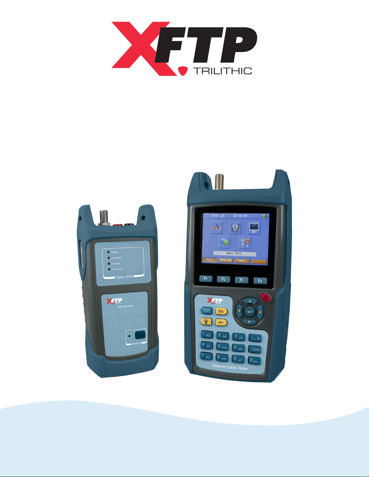
Wild-Cat
Ethernet Cable Tester
Operation Manual
Page 2

Page 3

Trilithic Company Profile
Trilithic is a privately held manufacturer founded in 1986 as an engineering and assembly
company that built and designed customer-directed products for telecommunications, military, and
industrial customers. From its modest beginnings as a two-man engineering team, Trilithic grew
over the years and broadened its offerings of RF and microwave components by adding
broadband solutions to its product line. This was accomplished with the acquisition of
components manufacturer Cir-Q-Tel and instruments manufacturer Texscan.
Today, Trilithic is an industry leader providing telecommunications solutions for major broadband,
RF, and microwave markets around the world. As an ISO 9000:2001 certified company with over
40 years of collective expertise in engineering and custom assembly, Trilithic is dedicated to
providing quality products, services, and communications solutions that exceed customer
expectations.
Trilithic is comprised of five major divisions:
Broadband Instruments and Systems
Offers test, analysis, and quality management solutions for the major cable television
systems worldwide.
RF Microwave Components
Provides components and custom subsystems for companies specializing in cellular,
military, and other wireless applications.
Emergency Alert Systems
Leading supplier of government-mandated emergency alert systems used by broadcast
TV, cable TV, IPTV, DBS, and radio stations.
XFTP
Offers a specialty line of field technical products for cable operators and technicians, as
well as a line of products for installing electronics in the home of the future.
Page 4

THIS PAGE LEFT INTENTIONALLY BLANK
Wild-Cat Ethernet Cable Tester - Operation Manual
2
Page 5

Table of Contents
1. General Information .............................................................................................................. 7
Helpful Website ..................................................................................................................... 7
Where to Get Technical Support .............................................................................................7
How this Manual is Organized ................................................................................................ 8
Conventions Used in this Manual ...........................................................................................8
Precautions ........................................................................................................................... 9
2. Introduction ......................................................................................................................... 11
What is the Wild-Cat? .......................................................................................................... 11
Equipment Supplied with the Wild-Cat .................................................................................12
3. Walkthrough ........................................................................................................................13
A Guided Tour of the Wild-Cat Main Unit ..............................................................................13
Front & Rear View ..........................................................................................................13
Top View ........................................................................................................................14
Right Side View .............................................................................................................14
Key Pad .........................................................................................................................15
Power On/Off Key ..................................................................................................... 15
Function Keys ..........................................................................................................15
Enter Key .................................................................................................................15
Arrow Keys ...............................................................................................................15
TEST Key................................................................................................................. 16
Quit/Esc Key ............................................................................................................ 16
LCD Backlight Key ...................................................................................................16
Backspace Key ........................................................................................................16
Entering Alphanumeric Characters ..........................................................................17
Display Screen ............................................................................................................... 18
A Guided Tour of the Wild-Cat Remote Unit .......................................................................... 19
Front & Rear View ..........................................................................................................19
Top View ........................................................................................................................20
Right Side View .............................................................................................................20
Left Side View ................................................................................................................20
Charging the Battery ............................................................................................................21
Updating Firmware & Software ............................................................................................21
Main Unit Update............................................................................................................ 22
Remote Unit Update ....................................................................................................... 22
Wild-Cat Ethernet Cable Tester - Operation Manual
3
Page 6

4. Setup ................................................................................................................................... 23
Overview ............................................................................................................................. 23
Setting Menu Icons .........................................................................................................24
Test Standard Configuration .................................................................................................26
Nominal Velocity of Propagation (NVP) Settings ..................................................................26
Language and Unit Settings .................................................................................................27
Language ....................................................................................................................... 27
Units ............................................................................................................................... 27
Job Information Settings ...................................................................................................... 28
Opening a Job................................................................................................................ 28
Create a New Job .......................................................................................................... 28
Job Name................................................................................................................. 28
Template .................................................................................................................. 28
Site Information ........................................................................................................29
Inspector Information ................................................................................................ 29
Edit an Existing Job........................................................................................................ 30
Copy an Existing Job...................................................................................................... 30
Delete an Existing Job.................................................................................................... 30
Transferring a Job to a USB Flash Drive ......................................................................... 30
Job Templates Settings........................................................................................................ 31
Opening & Editing a Job Template .................................................................................31
Create a New Job Template ........................................................................................... 31
Template Name ....................................................................................................... 31
Site Information ........................................................................................................31
Inspector Information ................................................................................................ 32
Copy an Existing Job Template....................................................................................... 32
Delete an Existing Job Template..................................................................................... 32
Time and Date Settings ....................................................................................................... 33
LCD Backlight Timer & System Power Settings ................................................................... 33
LCD Brightness Settings ..................................................................................................... 34
Configuration Management .................................................................................................. 34
Opening a Configuration................................................................................................. 34
Create a New Configuration ...........................................................................................35
Delete an Existing Configuration .....................................................................................35
Importing a Configuration from a USB Flash Drive .......................................................... 35
Transferring a Configuration to a USB Flash Drive .......................................................... 36
Default Settings Restore ...................................................................................................... 36
Wild-Cat Ethernet Cable Tester - Operation Manual
4
Page 7

5. Testing ................................................................................................................................. 37
Overview ............................................................................................................................. 37
Test Menu Icons .............................................................................................................. 38
Testing Models..................................................................................................................... 39
Channel Testing Model ...................................................................................................39
Permanent Link Testing Model........................................................................................ 40
Calibration ........................................................................................................................... 41
Channel Calibration ........................................................................................................ 41
Permanent Link Calibration ............................................................................................ 42
Auto Test .............................................................................................................................43
Add a Cable for Testing ..................................................................................................44
Cable Name .............................................................................................................44
Cable Type ...............................................................................................................44
Testing Model ..........................................................................................................44
Running an Auto Test ...................................................................................................... 45
Detailed Auto Test Results ..............................................................................................46
TDR Test Results ..................................................................................................... 46
Delay Test Results ...................................................................................................46
Resistance Test Results........................................................................................... 47
RF Test Results........................................................................................................ 47
Auto Test Summary ........................................................................................................48
Delete an Existing Cable ................................................................................................49
Transferring a Cable to a USB Flash Drive ..................................................................... 49
Manual Test .........................................................................................................................50
Data Cable.....................................................................................................................51
Standards Test ......................................................................................................... 51
Throughput Test ....................................................................................................... 52
Tone Test .................................................................................................................53
Phone Cable ..................................................................................................................54
TDR Test .................................................................................................................. 54
Tone Test .................................................................................................................54
2-Wire Cable..................................................................................................................54
TDR Test .................................................................................................................. 54
Tone Test .................................................................................................................54
Network Test ........................................................................................................................55
Results Comparison ............................................................................................................56
Wild-Cat Ethernet Cable Tester - Operation Manual
5
Page 8

6. System Information ............................................................................................................ 57
Overview ............................................................................................................................. 57
Info Menu Icons ...............................................................................................................58
Serial Number ..................................................................................................................... 59
Previous Calibration Date....................................................................................................59
Time and Date ..................................................................................................................... 59
Remaining Memory ..............................................................................................................60
Battery Information ............................................................................................................... 60
Support Information ..............................................................................................................61
7. ToolBox Software ............................................................................................................... 63
Overview ............................................................................................................................. 63
Installing the Wild-Cat ToolBox Software ..............................................................................63
Requirements ................................................................................................................. 63
Installing the Wild-Cat ToolBox ........................................................................................ 64
Learning Your Way Around ................................................................................................... 66
Before Starting ...............................................................................................................66
Importing Files ................................................................................................................ 67
Viewing Job Information & Measurement Results ...........................................................68
Import Path............................................................................................................... 68
Inspector Info ............................................................................................................ 69
Site Info .................................................................................................................... 69
Summary ................................................................................................................. 69
Wire Map .................................................................................................................. 70
Wire Map .................................................................................................................. 71
Printing Reports .............................................................................................................72
8. Appendix ............................................................................................................................. 73
Specifications ...................................................................................................................... 73
Length ............................................................................................................................73
Propagation Delay .........................................................................................................73
Delay Skew .................................................................................................................... 73
DC Resistance...............................................................................................................73
RF Frequency .................................................................................................................73
RF Items .........................................................................................................................74
Auto Tests ...................................................................................................................... 74
Manual Tests ..................................................................................................................74
Network Tests ................................................................................................................. 74
Display ........................................................................................................................... 74
Weight ........................................................................................................................... 74
Dimensions .................................................................................................................... 74
Warranty Information ............................................................................................................ 76
Wild-Cat Ethernet Cable Tester - Operation Manual
6
Page 9

Chapter 1
1. General Information
Helpful Website
The following website contains general information which may be of interest to you:
http://www.fieldtechproducts.com
XFTPs website contains product specifications and information, tips, release information,
marketing information, Frequently Asked Questions (FAQs), bulletins, product updates, and other
technical information.
Where to Get Technical Support
XFTP technical support is available Monday through Friday from 8:00AM to 5:00PM EST. Callers
in North America can dial 317-895-3600 or 800-344-2412 (toll free). International callers should
dial 317-895-3600 or fax questions to 317-895-3613. Technical support is also available through
e-mail at [email protected].
For quicker support response when calling or sending e-mail, please provide the following
information:
Your name and your company name
The technical point of contact (name, phone number, e-mail address)
The Wild-Cat serial number, firmware, and hardware version numbers
A detailed description of the problem you are having, including any error or information
messages
Wild-Cat Ethernet Cable Tester - Operation Manual
7
Page 10
How this Manual is Organized
This manual is divided into the following chapters:
Chapter 1, General Information provides XFTP contact information and describes how
this operation manual is structured
Chapter 2, Introduction introduces the equipment and features of the Wild-Cat
Chapter 3, Walkthrough describes the components of the Wild-Cat
Chapter 4, Setup describes the steps needed to perform the setup of the Wild-Cat
Chapter 5, Testing describes how to use the testing features of the Wild-Cat
Chapter 6, System Information describes how to view the system information of the
Wild-Cat
Chapter 7, Appendix shows the technical specifications and warranty of the Wild-Cat
Conventions Used in this Manual
This manual has several standard conventions for presenting information.
Connections, menus, menu options, fields and user-entered text and commands appear in
bold.
Section names, and web and e-mail addresses appear in italics.
A NOTE is information that will be of assistance to you related
to the current step or procedure.
A CAUTION alerts you to any condition that could cause a
mechanical failure or potential loss of data.
A WARNING alerts you to any condition that could cause
personal injury.
Wild-Cat Ethernet Cable Tester - Operation Manual
8
Page 11
Precautions
The input voltage of the adapter is 100 V-240 V (AC only).
A larger voltage will damage the meter.
Do not open the instrument.
Do not use the Wild-Cat in any manner not recommended by
the manufacturer.
Never attempt to insert any connector other than an 8-pin
modular connector into the RJ45 connector.
Never attempt to insert any connector other than a 6-pin
modular connector into RJ11 connector.
Never connect the tester to an active network except for a
network test. Doing so may disrupt network operation.
The battery MUST be charged with the AC to DC power adapter
and battery charger provided with the Wild-Cat. Using any other
adapter/charger may damage the battery.
Wild-Cat Ethernet Cable Tester - Operation Manual
9
Page 12

THIS PAGE LEFT INTENTIONALLY BLANK
Wild-Cat Ethernet Cable Tester - Operation Manual
10
Page 13

Chapter 2
2. Introduction
What is the Wild-Cat?
The Wild-Cat Ethernet Cable Tester is the ideal tester for measuring the performance of Class
C, Class D, and Class E Ethernet cable while adhering to ANSI/TIA/EIA-568-B and ISO/IEC
11801 standards. The Wild-Cat includes the following features and capabilities:
Documents that cables are built to support 10BASE-T, 100BASE-TX, and 1000BASE-T
networks
Supports American Standard TIA/EIA-568-B and International Standard ISO/IEC 11801
Cat5e Test results in less than 35 Seconds, Cat6 Results in less than 66 seconds
Tone Generator to locate jacks
Ping Test
ToolBox software for analyzing the results on a PC and generating a report of the results
An RJ45 connector for testing UTP/STP data cable, an F connector for testing coaxial
cables, an RJ11 connector for testing telephone cables, and 2 banana jacks for testing 2-
Wire cables
Reports PASS/FAIL results and 1000BASE-T capability judgment when an Auto Test has
finished
The ability to run about 3.5 hours on the Main Unit and 6 hours on the Remote Unit
Storage of at least 100 test results on the internal memory of the Wild-Cat and the ability to
copy these results to a USB flash drive
Wild-Cat Ethernet Cable Tester - Operation Manual
11
Page 14

Equipment Supplied with the Wild-Cat
The Wild-Cat includes the following equipment:
Main Unit with a rechargeable lithium-ion battery
Remote Unit with a rechargeable lithium-ion battery
2 Test Equipment Cables
2 RJ45 male to female adapters
AC to DC power adapter and battery charger
Operation manual and ToolBox software on CD
Wild-Cat Ethernet Cable Tester - Operation Manual
12
Page 15
3. Walkthrough
A Guided Tour of the Wild-Cat Main Unit
Front & Rear View
Chapter 3
1
2
3
4
1
5
6
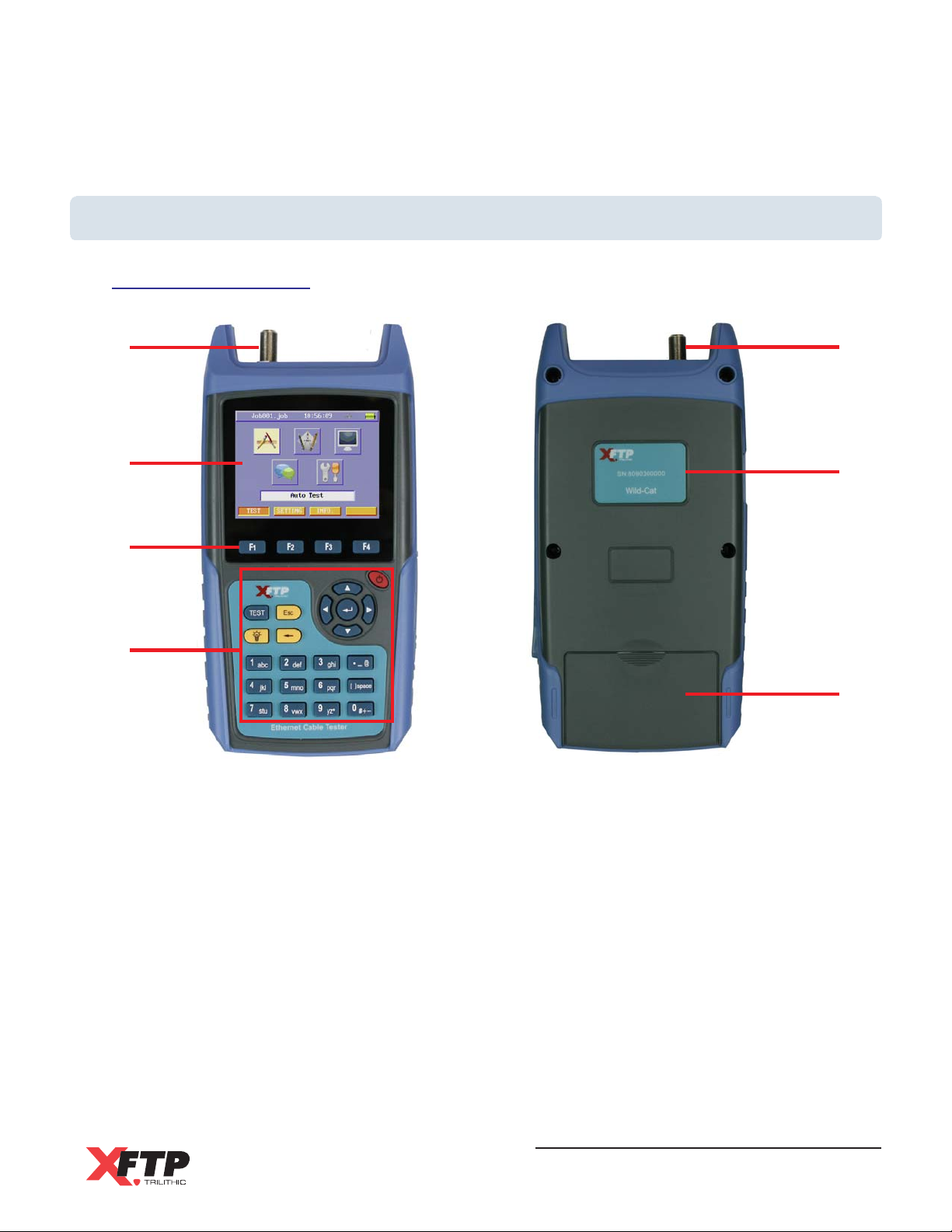
1. F-Type Connector - Used for testing of coaxial cable
2. Display - A high resolution color TFT LCD with backlight and adjustable brightness
3. Function Keys - Used to select from various soft function keys
4. Key Pad - Used to control the actions of the unit and display screen
5. Serial Number Label - This serial number is required for service and support
6. Battery Compartment - The location of the rechargeable Li-Ion battery
Wild-Cat Ethernet Cable Tester - Operation Manual
13
Page 16
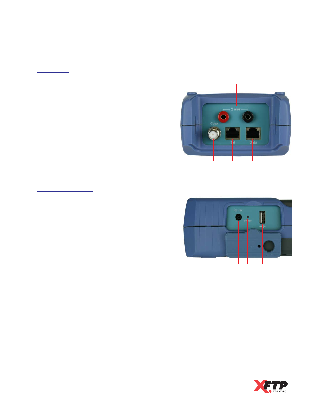
Top View
1. Banana Jacks - These are used for testing of
2-wire cables
2. F-Type Connector - This is used for testing of
coaxial cables
3. RJ11 Connector- This is used for testing of
telephone cables
4. RJ45 Connector - This is used for testing of
UTP/STP data cables
Right Side View
1. Charge Port - This is used to charge the Li-Ion
battery with the AC to DC power adapter and
battery charger
2. Charging LED - This is illuminated when
charging the battery
1
234
3. USB Port - This is used to transfer
configuration, job information, and Auto Test
measurement files to a connected USB Flash
Drive
Wild-Cat Ethernet Cable Tester - Operation Manual
14
132
Page 17
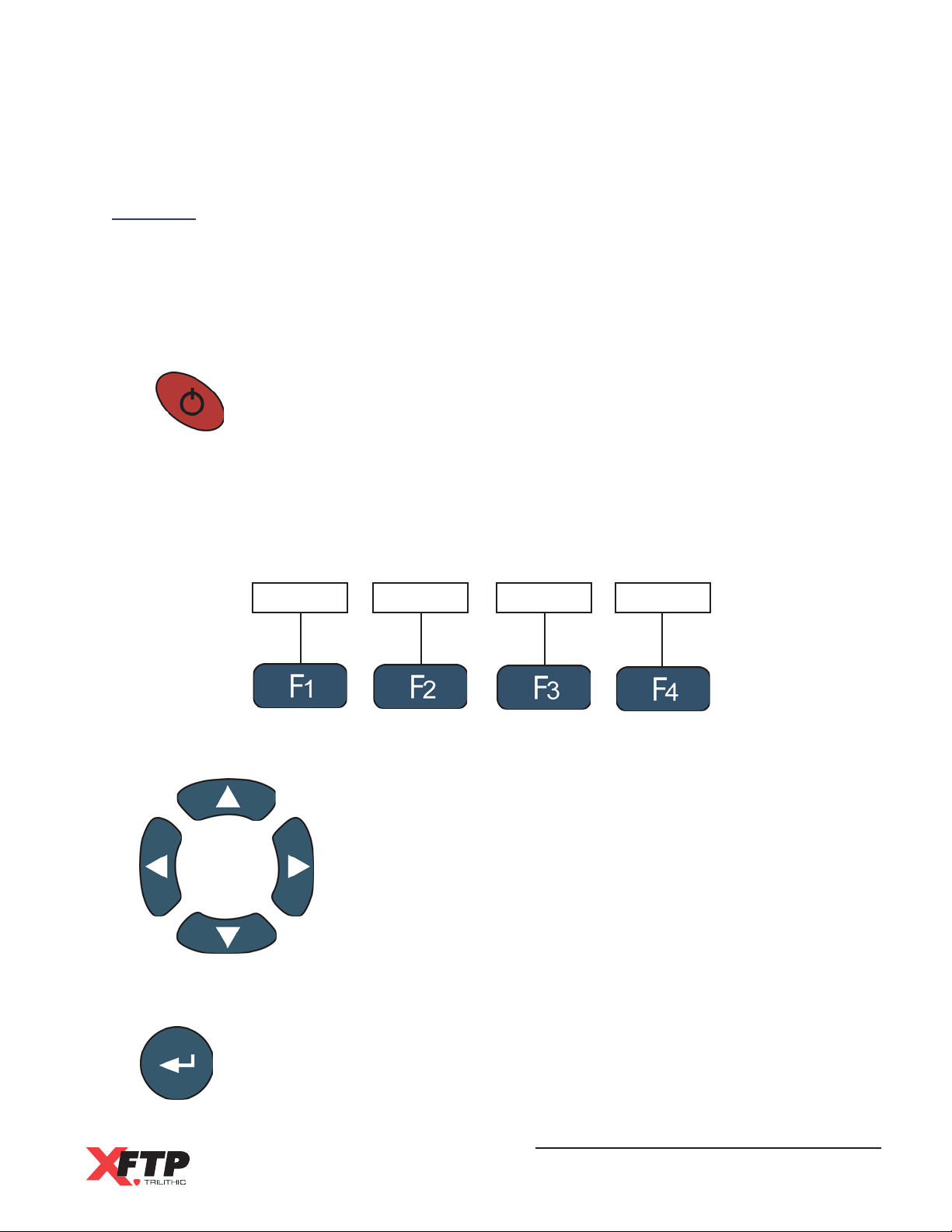
Key Pad
The key pad consists of the various keys used to access the functions of the Wild-Cat; Power
On/Off, four function, four arrow (up, down, left and right), Enter, Test, Quit/Esc, LCD Backlight,
Backspace, and twelve alphanumeric keys.
Power On/Off Key
Use the Power ON/OFF key to turn the device on and off.
Function Keys
The function keys are used to access various functions within the display menus. On
specific displays, four soft function keys appear at the bottom of the display. These soft
function keys correspond to the four function keys and provide additional commands.
Add Detail Summary Tag
Arrow Keys
Enter Key
The Enter key selects the highlighted item from a menu or the selected function
icon.
The arrow keys are used for navigating through the current menu.
A highlighted box will be displayed on the screen to indicate what
function is selected.
Wild-Cat Ethernet Cable Tester - Operation Manual
15
Page 18
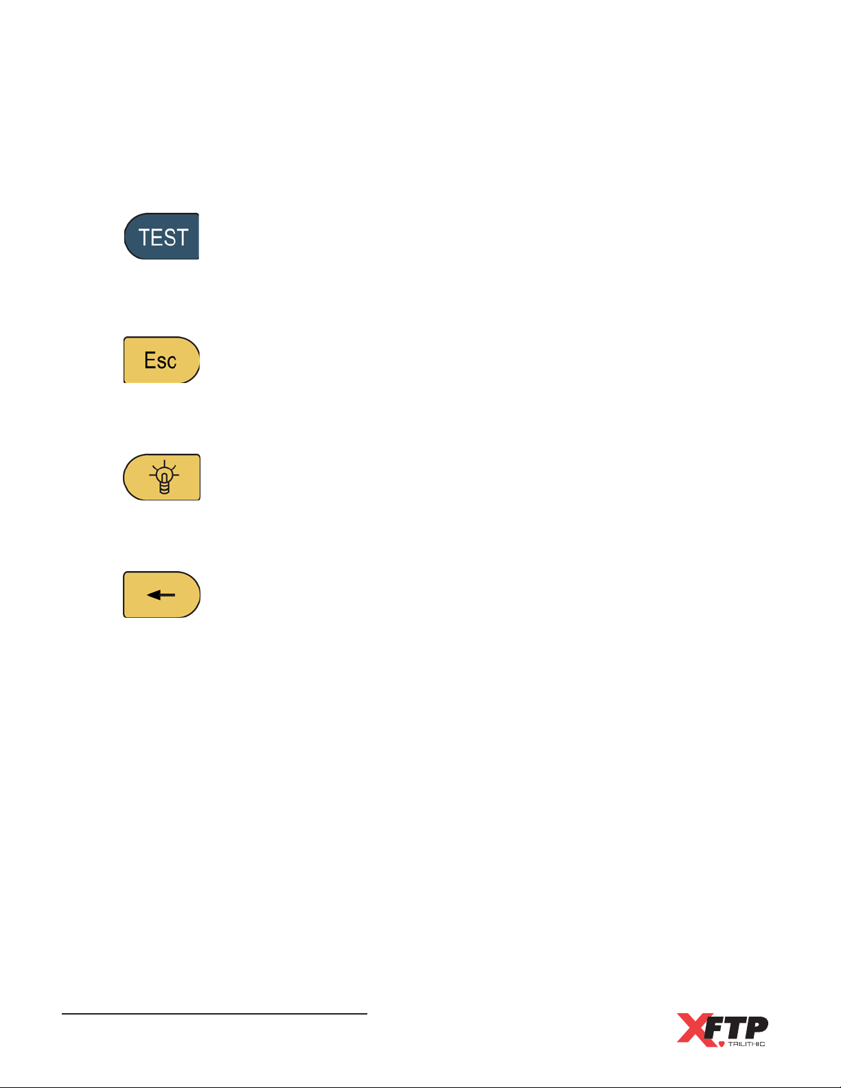
TEST Key
The TEST key starts an Auto Test for the selected cable.
Quit/Esc Key
The Esc key exits the current menu or item and returns to the previous menu.
LCD Backlight Key
The LCD Backlight key changes the LCD backlight between bright and dim
settings.
Backspace Key
The Backspace key deletes the last alphanumeric value when editing job
information and other items.
Wild-Cat Ethernet Cable Tester - Operation Manual
16
Page 19
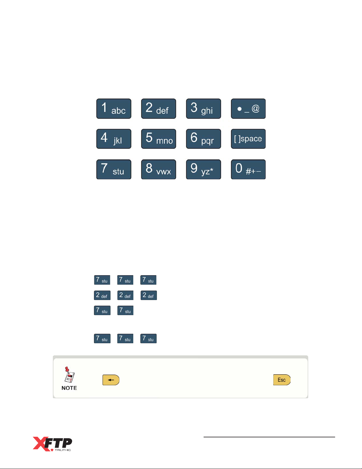
Entering Alphanumeric Characters
Alphanumeric data must be entered on several screens. Press the alphanumeric buttons
to enter the desired value. When you press a button in function mode, the first entry is the
number associated with the button. Press the same button repeatedly to scroll through the
letters associated with the button. To enter a second letter or number using a different
button, you can go directly to the second button for entry. If you want to enter a second letter
or number using the same button as the preceding character, pause momentarily between
entering characters to shift the cursor to a new number or letter.
For example, to enter TEST in the Name field, do the following:
1. Press + + to enter T in the field.
2. Press + + to enter E in the field.
3. Press + to enter S in the field
4. Pause briefly to shift the cursor to the next character.
5. Press + + to enter T in the field.
If you make an error when entering a number or a name, press
the key to go back and then re-enter it. Press the
key to escape from the operation.
Wild-Cat Ethernet Cable Tester - Operation Manual
17
Page 20
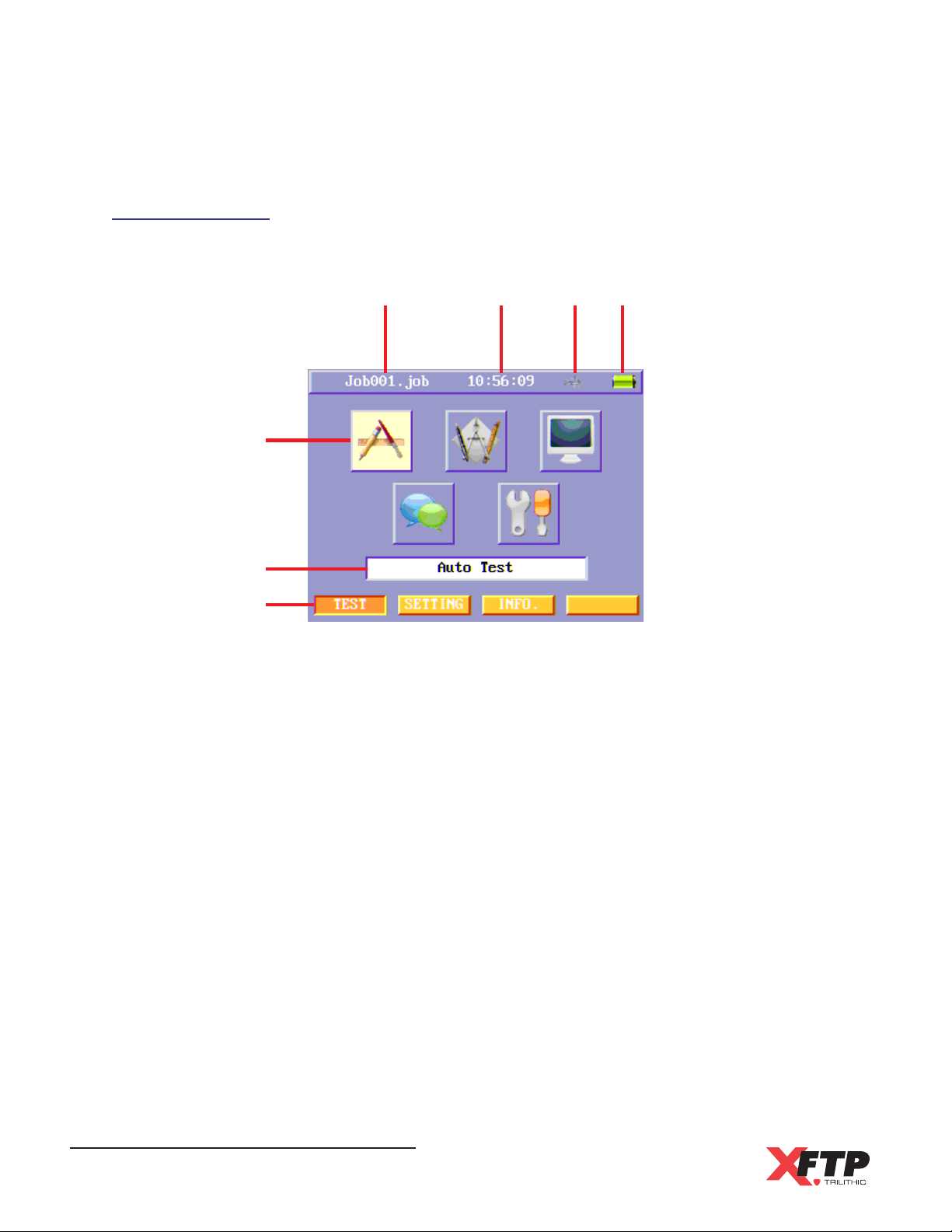
Display Screen
The display screen of the Wild-Cat Main Unit will appear as shown in the following image:
1
5
6
7
1. Job Name - Displays the name of the currently selected job
2. Current Time - Displays the current time of the Wild-Cat
2 3 4
3. USB Status Icon - Displays the status of a connected USB flash drive
4. Battery Status Icon - Displays the charging status of the Wild-Cat
5. Function Icons - These icons are used to enter the various functions of the Wild-Cat
6. Function Descriptions - Displays a description of the highlighted function icon
7. Soft Function Keys - These keys correspond to each physical function key
Wild-Cat Ethernet Cable Tester - Operation Manual
18
Page 21
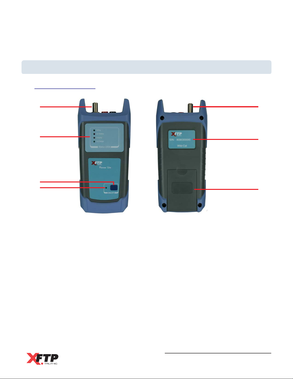
A Guided Tour of the Wild-Cat Remote Unit
Front & Rear View
1
2
3
4
1. F-Type Connector - Used for testing of coaxial cable
2. Status LEDs
1
5
6
Testing - This is illuminated while performing a test
Low Battery - This is illuminated when the battery charge is low
Charging - This is illuminated when charging the battery
Full Charge - This is illuminated when the battery charge is full and the unit is
connected to the AC to DC power adapter & battery charger
3. Power ON/OFF Key - Used to turn the power to the unit on and off
4. Power ON/OFF LED - This is illuminated when power to the unit is on
5. Serial Number Label - This serial number is required for service and support
6. Battery Compartment - The location of the rechargeable Li-Ion battery
Wild-Cat Ethernet Cable Tester - Operation Manual
19
Page 22
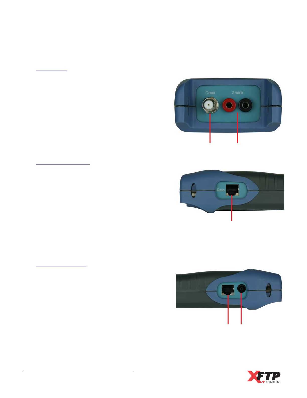
Top View
1. F-Type Connector - This is used for testing of
coaxial cable
2. Banana Jacks - These are used for testing of
2-wire cable
Right Side View
1. RJ45 Connector - This is used for testing of
UTP/STP data cable
Left Side View
1. RJ11 Connector- This is used for testing of
telephone cable
1
2
1
2. Charge Port - This is used to charge the Li-Ion
battery with the AC to DC power adapter and
battery charger
Wild-Cat Ethernet Cable Tester - Operation Manual
20
12
Page 23
Charging the Battery
When the Main Unit battery is low, the battery status icon will blink. To recharge, connect the AC to
DC power adapter and battery charger to the Charge Port of the Main Unit. The Charging LED
will be illuminated when charging.
When the Remote Unit battery is low, the Low Battery LED will be illuminated. To recharge,
connect the AC to DC power adapter and battery charger to the Charge Port of the Remote Unit.
The Charging LED will be illuminated when charging.
The Main Unit and Remote Unit will automatically shut down when the battery power is too low.
Updating Firmware & Software
Users can update the following items using a USB Flash Drive connected to the Main Unit:
OS Kernel
Main Unit Firmware
Main Unit Software
Remote Unit Firmware
Do not take the battery out of the main unit or remote unit
during the update process.
Do not disconnect the USB Flash Drive from the Main Unit
during the update process.
Be sure that the Main Unit has enough free memory and both
the Main and Remote Units have enough battery power.
Wild-Cat Ethernet Cable Tester - Operation Manual
21
Page 24

Main Unit Update
To update the Main Unit OS Kernel, Firmware, or Software, perform the following steps:
1. Copy the update file from a PC to a USB Flash Drive.
2. Before turning on the Main Unit, connect the USB Flash Drive to the Main Unit.
3. Press the Power ON/OFF key, the Main Unit will automatically find the update file and
run the update process.
4. A message box will appear indicating the update process is running.
5. When the update process is finished, the message box disappears and the Main Unit
will automatically shut down.
Remote Unit Update
To update the Remote Unit firmware, perform the following steps:
1. Copy the update file from a PC to a USB Flash Drive.
2. Turn on the Remote Unit.
3. Connect the Remote Unit to the Main Unit using one equipment cord.
4. Connect the USB Flash Drive to the Main Unit and turn on the Main Unit.
5. Go to the Info menu and select the Serial Number icon.
6. When the update process runs, a message box will appear on the Main Unit.
7. When the process is finished, the Remote Unit will automatically shut down.
Wild-Cat Ethernet Cable Tester - Operation Manual
22
Page 25
Chapter 4
4. Setup
Overview
The following sections describes how to adjust the settings of the Wild-Cat.
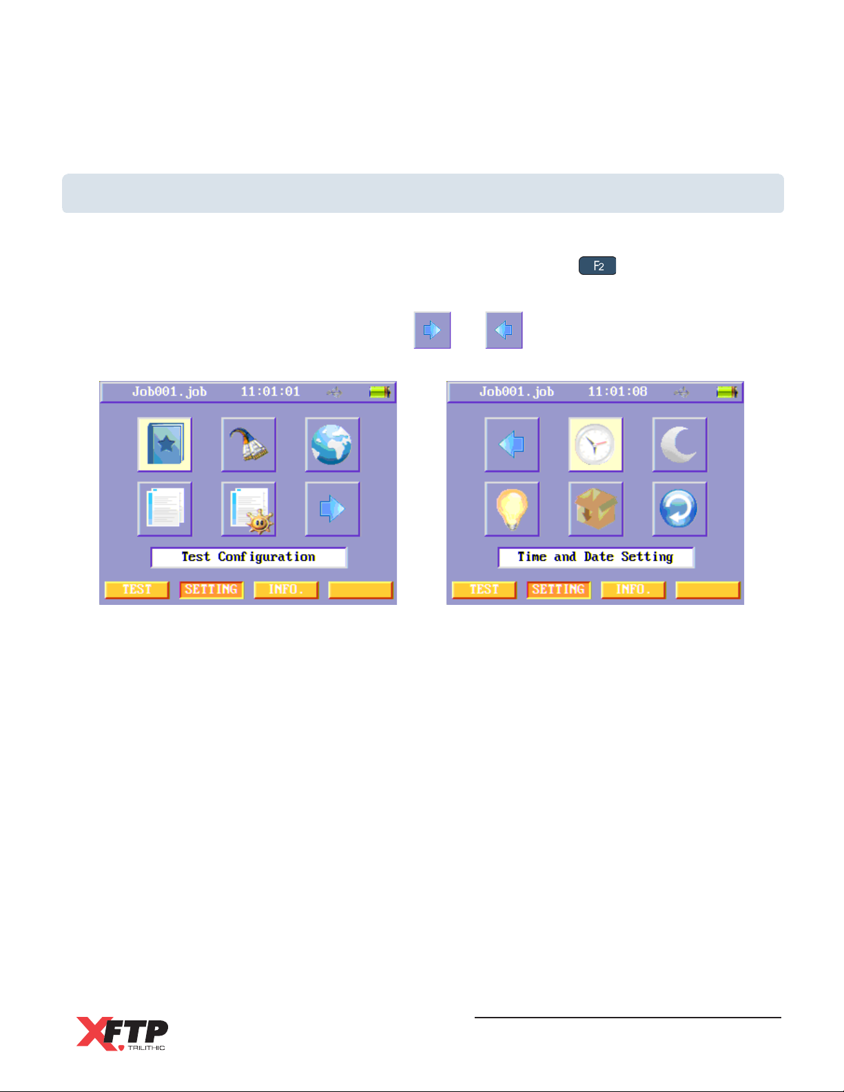
To enter the SETTING menu from the TEST or INFO menus, press the key to select the
SETTING soft function key.
There are two SETTING menu pages. Use the and icons to switch between pages.
Wild-Cat Ethernet Cable Tester - Operation Manual
23
Page 26
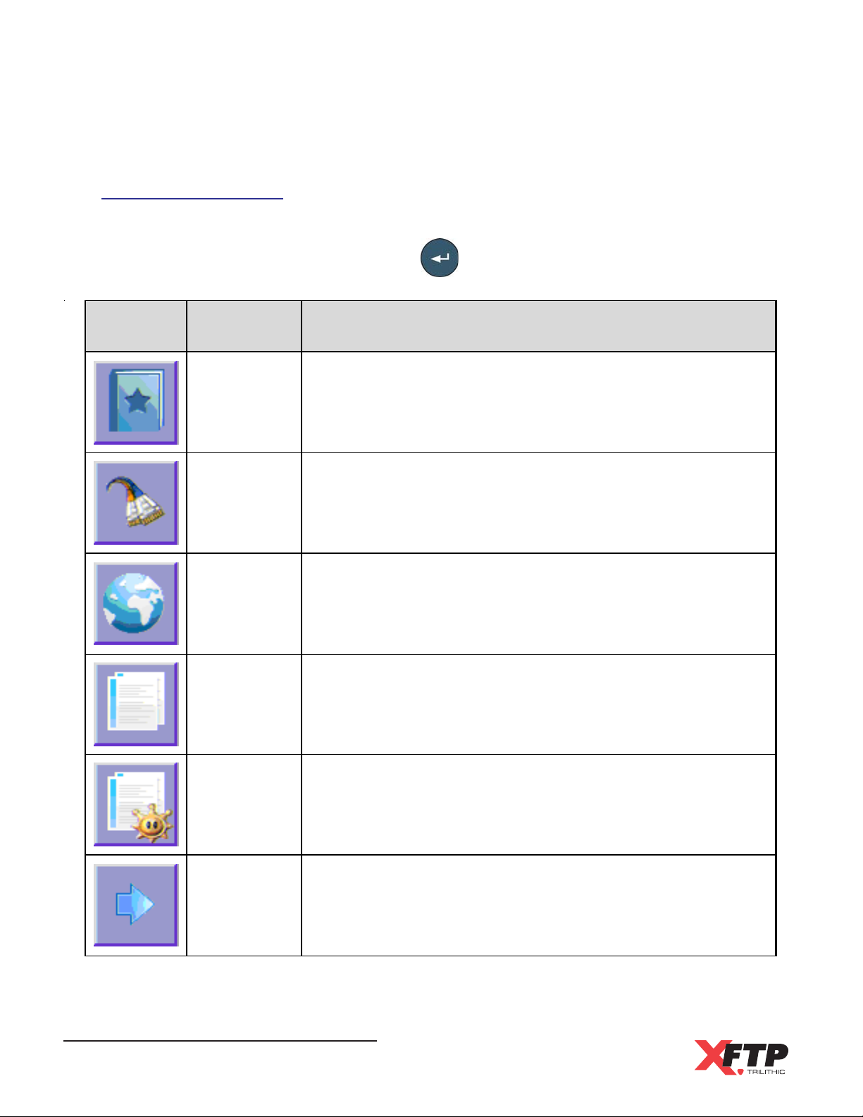
Setting Menu Icons
The following functions are available from the SETTING menu. Use the arrow keys to highlight
the desired function icon and then press the key to enter the corresponding function.
Icon Function Purpose
Test
Configuration
NVP Settings
Lan guage &
Unit Settings
Job
Information
Setting
Job
Tem plates
Setting
Select the configuration standard to use when testing
Adjust the Nominal Velocity of Propagation for the type of
w ir es that ar e being test ed
Select the display language and th e m easurement units to be
used by th e teste r
T his m enu is used t o add, copy, edit, and delete jo b
in formation and t r ansfer the job inform ati on to a USB Dr ive
T his m enu is used t o add, copy, edit, and delete job
templates which include site and inspector information
Go to Next
Page
Wild-Cat Ethernet Cable Tester - Operation Manual
24
Enter the second page of the Settings Menu
Page 27
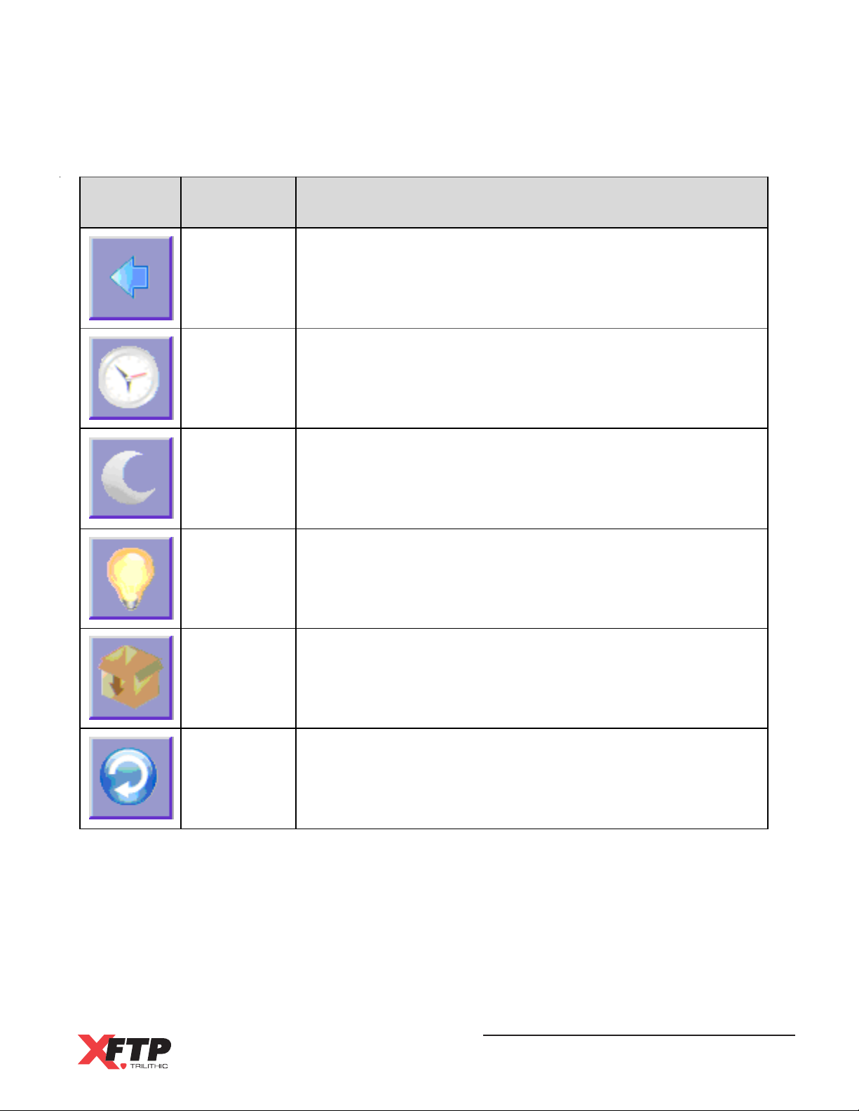
Icon Function Purpose
Go to
Previous
Page
Time and
Date
Settings
LCD &
System
Power
Settings
LCD
Brightness
Settings
Enter the first p age of the Settings Menu
Adjust the time and date settings of the tester
Adjust the automatic shutdown timer for the tester’s
process or and LCD screen
A d just t h e br ightne s s of the LC D sc r e en
Configuration
Management
This menu is used to add, co py, edit, and delete system
configuration files and import/export the files to/from a USB
Drive
Default
Settings
This is used to restore th e teste r to its default settings
Restore
Wild-Cat Ethernet Cable Tester - Operation Manual
25
Page 28
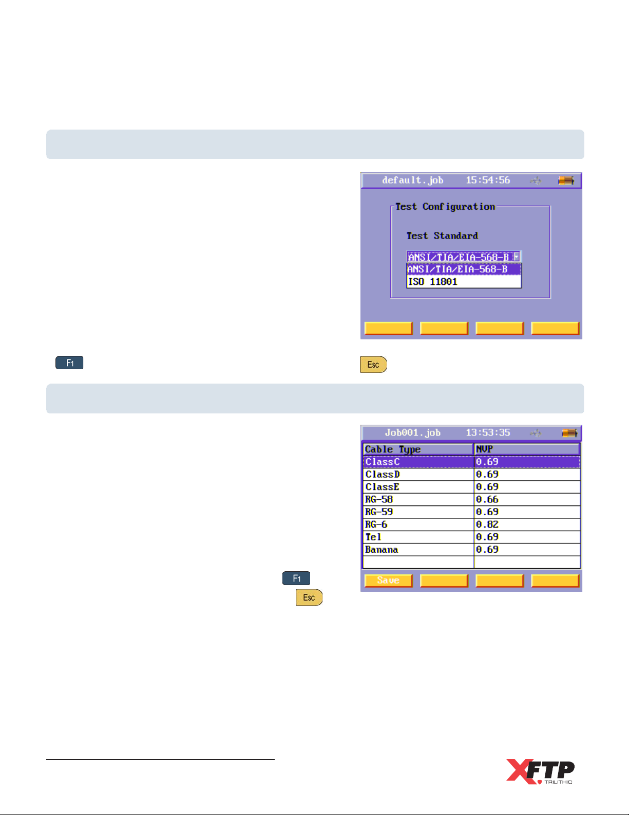
Test Standard Configuration
This instrument supports two cable test standards when
testing UTP/STP cabling:
International Standard ISO/IEC 11801
American Standard TIA/EIA-568-B
To change the test standard, press the Enter key to
select the Test Standard field and then use the arrow
keys to highlight the desired test standard.
Once the test standard has been highlighted, press the
Enter key to accept the test standard.
To save the change to the test standard, press the
key to select the Save soft function key or press the key to exit without saving.
Nominal Velocity of Propagation (NVP) Settings
A list of different types of cables and the NVP of each
is displayed and can be adjusted from the NVP menu.
To change the NVP, use the arrow keys to highlight the
type of cable and then press the Enter key.
Use the alphanumeric key pad to make changes to the
NVP value.
Once the NVP value has been changed, press the
Enter key to accept the NVP value.
To save the NVP value changes, press the key to
select the Save soft function key or press the key
to exit without saving.
Wild-Cat Ethernet Cable Tester - Operation Manual
26
Page 29
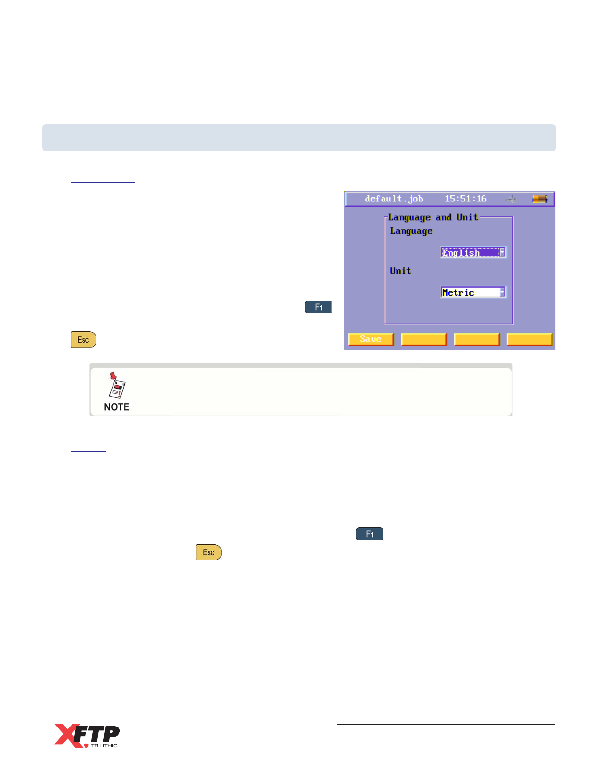
Language and Unit Settings
Language
Use the arrow keys to highlight the Language field
and then press the Enter key.
Use the arrow keys to highlight the desired
language.
Once the language has been highlighted, press the
Enter key to accept the language.
To save the change to the language, press the
key to select the Save soft function key or press the
key to exit without saving.
The Wild-Cat Ehternet Cable Tester only support the English
language at this time.
Units
Use the arrow keys to highlight the Unit field and then press the Enter key.
Use the arrow keys to highlight the desired units.
Once the units have been highlighted, press the Enter key to accept the units.
To save the change to the measurement units, press the key to select the Save soft
function key or press the key to exit without saving.
Wild-Cat Ethernet Cable Tester - Operation Manual
27
Page 30
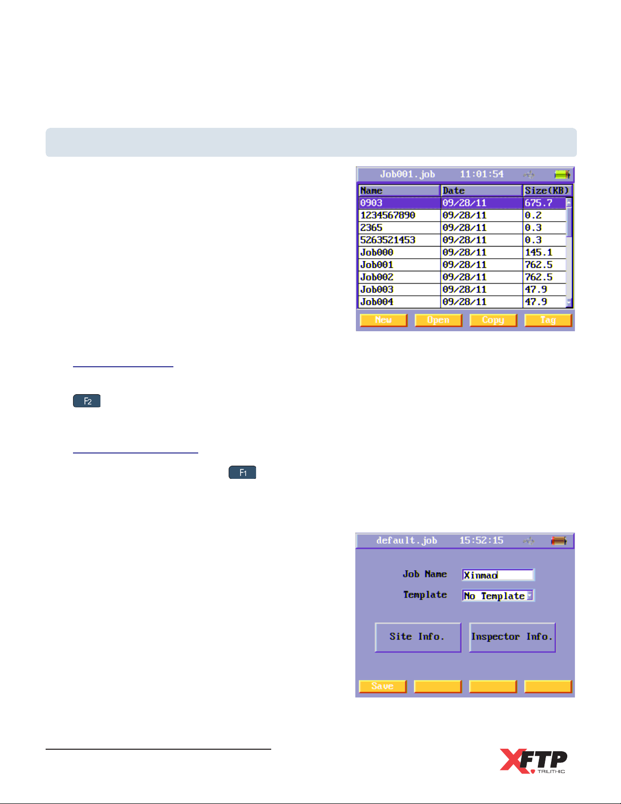
Job Information Settings
This menu displays a list of all jobs stored in internal
memory of the Main Unit. Each job acts as a file folder
that includes multiple cables. Detailed auto test results
are saved for each cable in the job folder.
Once the inspector comes to a new site, the inspector
creates a new job, and all the cables tested in this site
are saved in this job folder. Users can set the
properties for one job folder to include site and
inspector information.
Opening a Job
To open a job for testing, use the arrow keys to highlight the desired job and then press the
key to select the Open soft function key. Once the job has been opened, the name of the
job will appear at the top of the display.
Create a New Job
To create a new job press the key to select the New soft function key. The new job menu
will appear. Use the arrow keys to move between the following fields:
Job Name
Use the alphanumeric key pad to enter a name
to easily distinguish between jobs in the Main
Unit memory.
Template
Press the Enter key to select the Template
field and then use the arrow keys to highlight the
desired template. Once the template has been
highlighted, press the Enter key to accept the
template.
Wild-Cat Ethernet Cable Tester - Operation Manual
28
Page 31
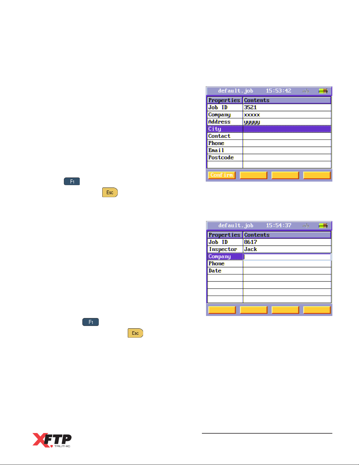
Site Information
To edit the site information of the selected job,
use the arrow keys to highlight the Site Info
button and then press the Enter key.
Use the arrow keys to highlight the desired field
and then press the Enter key to edit the field.
Use the alphanumeric keypad to enter the new
information and then press the Enter key to
accept the new information.
To save the change to the site information, press
the key to select the Confirm soft function
key or press the key to exit without saving.
Inspector Information
To edit the inspector information of the selected
job, use the arrow keys to highlight the
Inspector Info button and then press the Enter
key.
Use the arrow keys to highlight the desired field
and then press the Enter key to edit the field.
Use the alphanumeric keypad to enter the new
information and then press the Enter key to
accept the new information.
To save the change to the inspector information,
press the key to select the Confirm soft
function key or press the key to exit without saving.
Wild-Cat Ethernet Cable Tester - Operation Manual
29
Page 32
Edit an Existing Job
From the Job Information menu, use the arrow keys to highlight the name of an existing job
and then press the Enter key. The Job Name, Site Information, and Inspector Information can
be edited as shown in the previous section.
Copy an Existing Job
From the Job Information menu, use the arrow keys to highlight an existing job to copy and
then press the key to select the Copy soft function key. A new job will be created with the
the same properties of the existing job. Enter a new name for the job and then press the Enter
key.
Delete an Existing Job
From the Job Information menu, use the arrow keys to highlight an existing job and then
press the key to select the Tag soft function key. Repeat this process for all jobs that you
wish to delete. To select all jobs, press the key to select the Tag All soft function key.
Once all the jobs to be deleted are tagged, press the key to select the Delete soft
function key. A Warning will appear, press the Enter key to delete the jobs or press any other
key to exit without deleting the jobs.
Transferring a Job to a USB Flash Drive
Connect a USB Flash drive to the USB Port of the Main Unit
before proceeding with this section.
From the Job Information menu, use the arrow keys to highlight an existing job and then
press the key to select the Tag soft function key. Repeat this process for all jobs that you
wish to transfer to a USB Flash Drive. To transfer all jobs, press the key to select the
Tag All soft function key.
Once all the files to be transferred are tagged, press the key to select the To Udisk soft
function key. An Information window will appear to display the file transfer progress.
Wild-Cat Ethernet Cable Tester - Operation Manual
30
Page 33
Job Templates Settings
This menu displays a list of all job templates stored in internal memory of the Main Unit. Each
template created can be selected when creating a new job. Each job template includes site and
inspector information. When a job template is selected when creating a new job, the Inspector
and Site Information are automatically copied to the new job.
Opening & Editing a Job Template
To open a job template, use the arrow keys to highlight the desired job template and then
press the Enter key. Once the job template has been opened, the Template Name, Site
Information, and Inspector Information can be edited as shown in the following section.
Create a New Job Template
To create a new job template press the key to select the New soft function key. The new
job template menu will appear. Use the arrow keys to move between the following fields:
Template Name
Use the alphanumeric key pad to enter a name to easily distinguish between job templates
in the Main Unit memory.
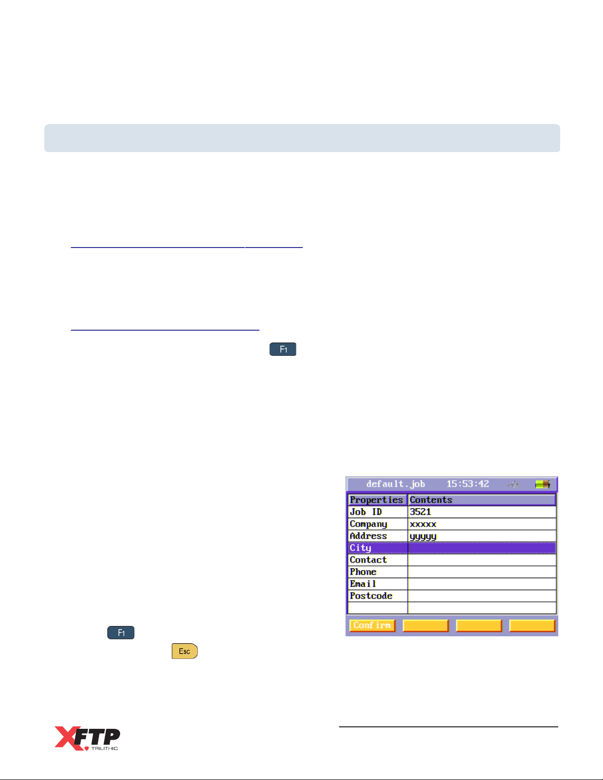
Site Information
To edit the site information of the selected job
template, use the arrow keys to highlight the
Site Info button and then press the Enter key.
Use the arrow keys to highlight the desired field
and then press the Enter key to edit the field.
Use the alphanumeric keypad to enter the new
information and then press the Enter key to
accept the new information.
To save the change to the site information, press
the key to select the Confirm soft function
key or press the key to exit without saving.
Wild-Cat Ethernet Cable Tester - Operation Manual
31
Page 34
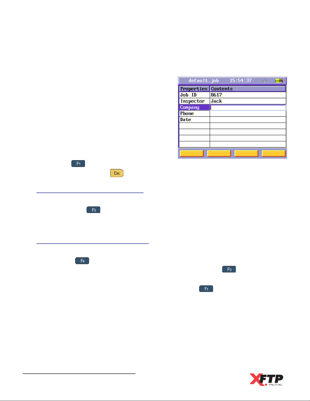
Inspector Information
To edit the inspector information of the selected
job template, use the arrow keys to highlight the
Inspector Info button and then press the Enter
key.
Use the arrow keys to highlight the desired field
and then press the Enter key to edit the field.
Use the alphanumeric keypad to enter the new
information and then press the Enter key to
accept the new information.
To save the change to the inspector information,
press the key to select the Confirm soft
function key or press the key to exit without saving.
Copy an Existing Job Template
From the Job Template menu, use the arrow keys to highlight an existing job template to copy
and then press the key to select the Copy soft function key. A new job template will be
created with the same properties of the existing job template. Enter a new name for the job
template and then press the Enter key.
Delete an Existing Job Template
From the Job Template menu, use the arrow keys to highlight an existing job template and
then press the key to select the Tag soft function key. Repeat this process for all job
templates that you wish to delete. To select all job templates, press the key to select the
Tag All soft function key.
Once all the job templates to be deleted are tagged, press the key to select the Delete
soft function key. A Warning will appear, and then press the Enter key to delete the job
templates or press any other key to exit without deleting the job templates.
Wild-Cat Ethernet Cable Tester - Operation Manual
32
Page 35
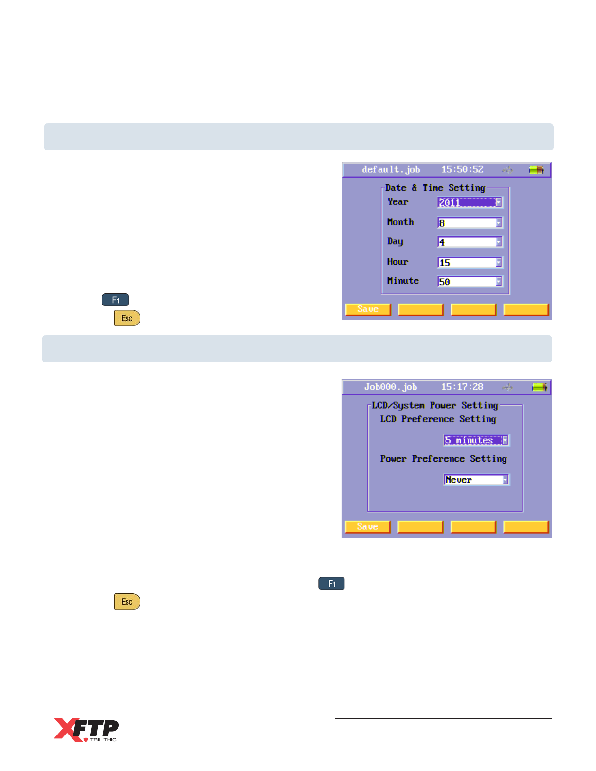
Time and Date Settings
To change the time and date settings, use the arrow
keys to highlight the desired setting and then press the
Enter key to select the field.
Use the arrow keys to select the desired values and
then, press the Enter key to accept the change.
Repeat these steps for each of the time and date
settings.
To save the changes to the time and date settings,
press the key to select the Save soft function key
or press the key to exit without saving.
LCD Backlight Timer & System Power Settings
The Main Unit can be set to automatically shut down
the LCD backlight or power down to save power when
the unit is not being used.
When the LCD backlight turns off because the timeouts
has been reached, it can be turned back on by
pressing any key.
To change the power settings, use the arrow keys to
highlight the desired setting and then press the Enter
key to select the field.
Use the arrow keys to select the desired values and
then, press the Enter key to accept the change.
Repeat these steps for each of the power settings.
To save the changes to the power settings, press the key to select the Save soft function key
or press the key to exit without saving.
Wild-Cat Ethernet Cable Tester - Operation Manual
33
Page 36
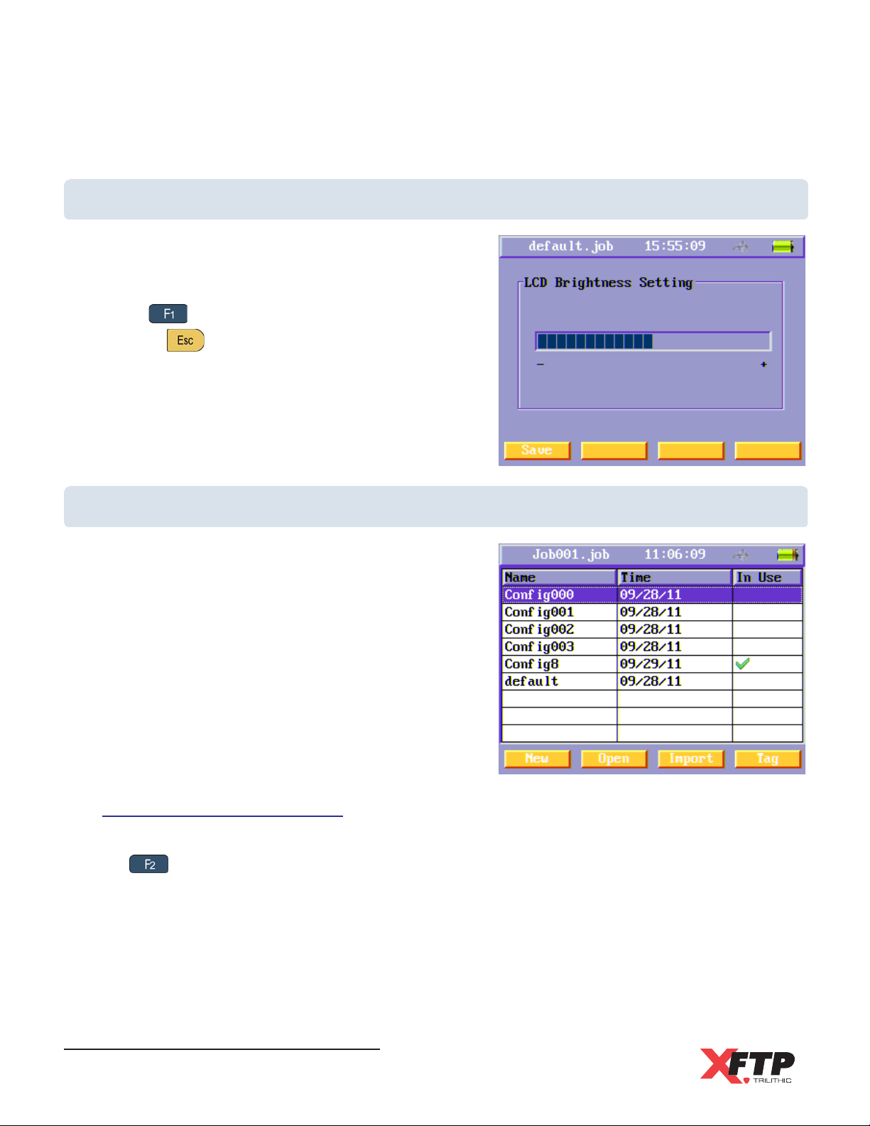
LCD Brightness Settings
To change the LCD brightness settings, use the arrow
keys to increase/decrease the brightness.
To save the changes to the LCD brightness settings,
press the
or press the key to exit without saving.
key to select the Save soft function key
Configuration Management
Users can manage configuration files using this menu.
After performing a setup of the Main Unit, these
settings can be saved to a configuration file. The
configuration file includes all of the instrument settings.
Opening a Configuration
To open a configuration, use the arrow keys to highlight the configuration file and then press
the key to select the Open soft function key. Once the configuration file has been
opened, an Information menu will appear. Select any key to continue.
Wild-Cat Ethernet Cable Tester - Operation Manual
34
Page 37
Create a New Configuration
After performing a setup of the Main Unit, press the key to select the New soft function
key. A new configuration file will appear.
To edit the configuration file name, press the Enter key and then use the alphanumeric keypad
to enter a new file name. Press the Enter key to accept the changes.
Delete an Existing Configuration
From the Configuration Management menu, use the arrow keys to highlight an existing job
configuration and then press the key to select the Tag soft function key. Repeat this
process for all configurations that you wish to delete. To select all configuration files, press the
key to select the Tag All soft function key.
Once all the configuration files to be deleted are tagged, press the key to select the
Delete soft function key. A Warning will appear, and then press the Enter key to delete the
configuration files or press any other key to exit without deleting the files.
Importing a Configuration from a USB Flash Drive
Connect a USB Flash drive to the USB Port of the Main Unit
before proceeding with this section.
From the Configuration Management menu, press the key to select the Import soft
function key. An Information window will appear to display the file transfer progress. The
imported configuration files will appear in the Configuration Management menu.
Wild-Cat Ethernet Cable Tester - Operation Manual
35
Page 38
Transferring a Configuration to a USB Flash Drive
Connect a USB Flash drive to the USB Port of the Main Unit
before proceeding with this section.
From the Configuration Management menu, use the arrow keys to highlight an existing
configuration and then press the key to select the Tag soft function key. Repeat this
process for all configuration files that you wish to transfer to a USB Flash Drive. To transfer all
files, press the key to select the Tag All soft function key.
Once all the files to be transferred are tagged, press the key to select the Export soft
function key. An Information window will appear to display the file transfer progress.
Default Settings Restore
Select the Default Setting Restore function icon to restore the Main Unit to the default settings. A
Warning will appear, and then press the Enter key to restore the default settings or press any
other key to exit without restoring the default settings.
Wild-Cat Ethernet Cable Tester - Operation Manual
36
Page 39
Chapter 5
5. Testing
Overview
The following sections describes how to perform tests using the Wild-Cat.
This section assumes you are at least familiar with the basic operation of the navigational tools
used in the Wild-Cat, so be sure to review Chapter 3: Walkthrough before proceeding through
this section.
To use some test functions, you may have to set up some basic parameters. Be sure you have
completed Chapter 4: Setup before proceeding through this section.
If this instrument is being used for the first time, the test equipment
should be calibrated before testing.
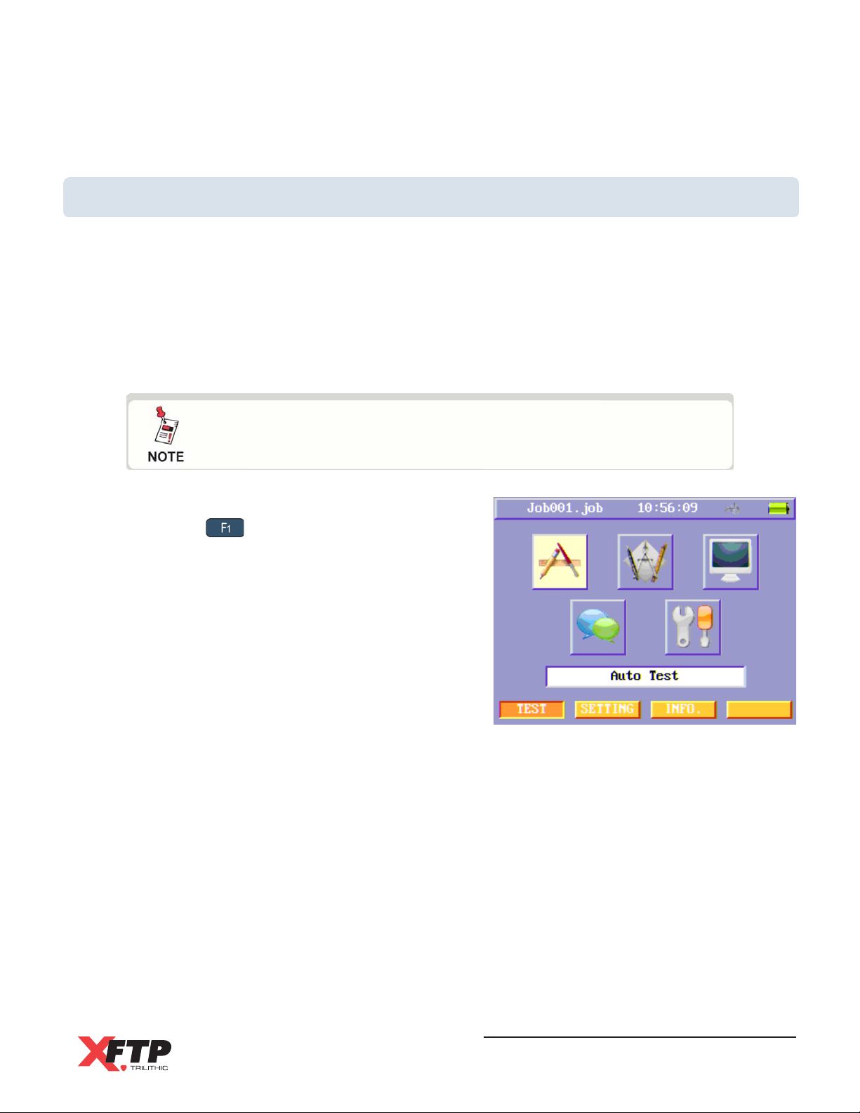
To enter the Test menu page from the Setting or Info
menus, press the key to select the TEST soft
function key.
Wild-Cat Ethernet Cable Tester - Operation Manual
37
Page 40
Test Menu Icons
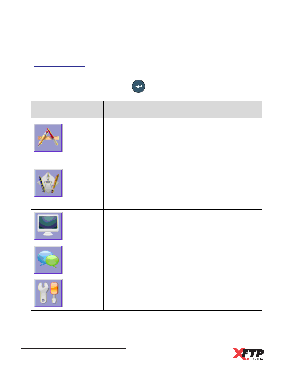
The following functions are available from the Test menu. Use the arrow keys to highlight the
desired function icon and then press the key to enter the corresponding function.
Icon Function Purpose
The A uto Tes t func tion is us ed t o per form a s eries of tests on
a se lected cable and returns a PASS/FAIL resul t
Auto Test
Manual Test
T his function includes; wir e m ap, le ngth, pr opagation de lay,
delay skew, DC loop resistance, insertion loss, NEXT, PS
N EXT, return loss, ACR, PS ACR, ELFEXT, PS ELFEXT
The M anual Test func tio n is us ed t o perfor m si ngle tests and
a dv anced tr oublesho oting without retur ning a PASS /F A IL
result
This func tion i n c lude s: th r oug hp u t, to ne, wi r e map, leng th ,
pro pa gation delay, del ay skew, DC loop resi stance, inse rtion
loss, NEXT, PS N EXT, return loss, ACR, PS ACR, ELFEXT,
PS ELFEXT
Network
Test
Results
Comparison
Calibration
Wild-Cat Ethernet Cable Tester - Operation Manual
38
T his function is used to perform a Ping test on the connected
network
This function is used to compare the results of two tests sideby - s i de
T his function is used to calibrat e th e test eq uipment c ables
that are us ed with the tester
Page 41
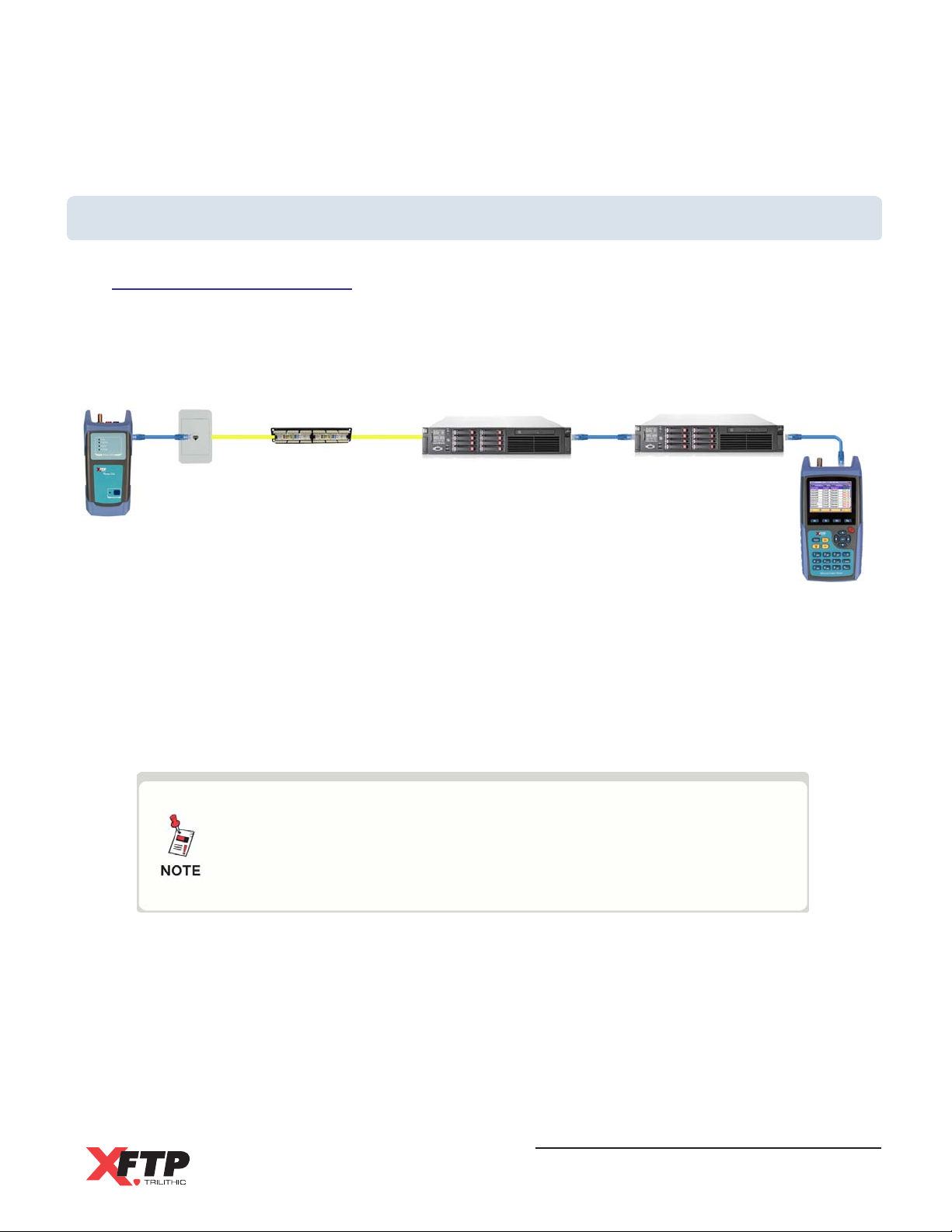
Testing Models
Channel Testing Model
The Channel testing model as defined in TIA and ISO standards is the complete cable path
that the network equipment uses to communicate when all equipment has been installed. This
includes the equipment show in the following image:
AB C D E
WA
A - Work Area Cable
B - Optional Transition Cable
C - Horizontal (Uninterrupted) Cable
D - Patch Cord or Jumper Cable
E - Telecom Room Equipment Cable
The image above includes the Main & Remote test units in place
of the typical network equipment. Connections to the typical
network equipment or the Main & Remote test units at each end
of the Channel are not included in the channel definition.
CP C1 C2
WA - Telecom Outlet
CP - Consolidation Point (Optional)
C1 - Horizontal Cross-Connect or Interconnect
C2 - Horizontal Cross-Connect or Interconnect
The total length of the optional transition cable and horizontal cable (B + C) shall not exceed a
length of 295 ft (90 m).
The total length of equipment, patch, jumper and work area cables (A + D + E) shall not exceed
a length of 33 ft (10 m).
The total length of all cabling shall not exceed 328 ft (100 m).
Wild-Cat Ethernet Cable Tester - Operation Manual
39
Page 42
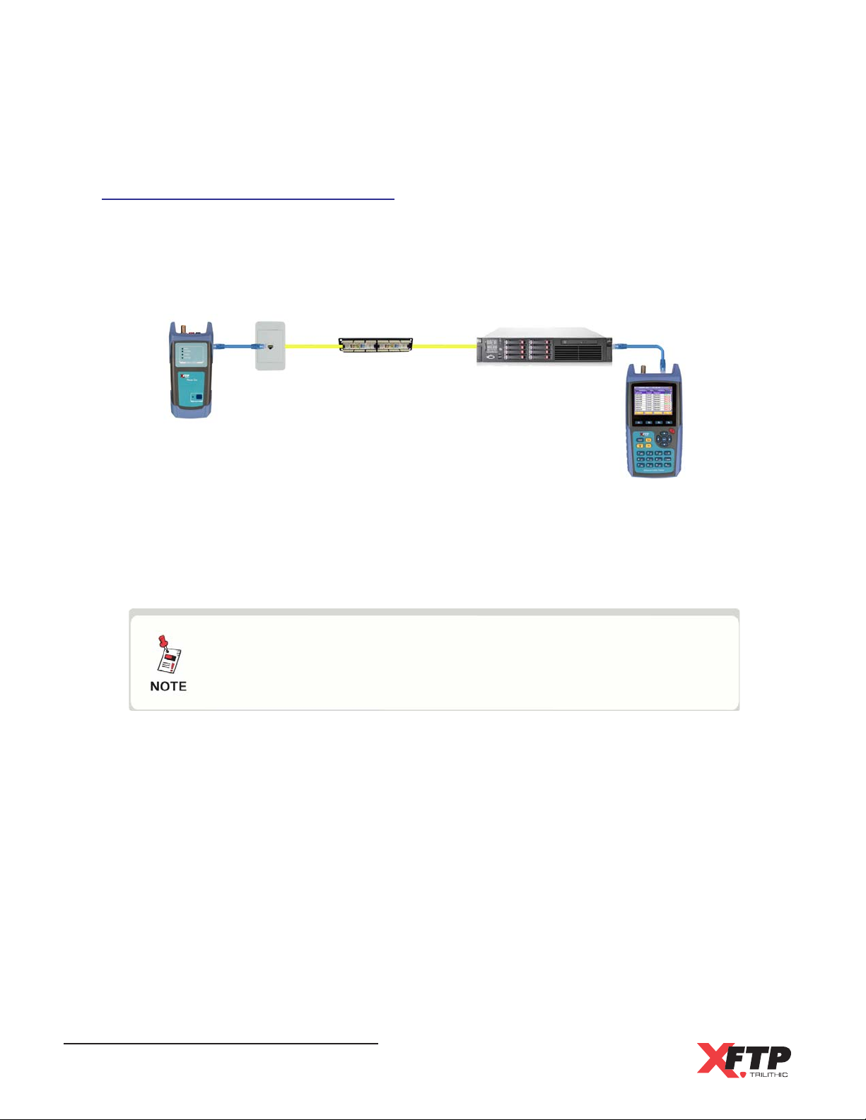
Permanent Link Testing Model
The Permanent Link testing model as defined in TIA and ISO standards is the permanently
installed cable path and does not include any equipment, patch, jumper, or work area cords.
This includes the equipment show in the following image:
AB C A
WA
A - Test Equipment Cable
B - Optional Transition Cable
C - Horizontal (Uninterrupted) Cable
Once the Main & Remote Units have been properly calibrated to
the test equipment cables, the cables will not contribute to any
measurement results.
The total length of the optional transition cable and horizontal cable (B + C) shall not exceed a
length of 295 ft (90 m).
CP C1
WA - Telecom Outlet
CP - Consolidation Point (Optional)
C1 - Horizontal Cross-Connect or Interconnect
Wild-Cat Ethernet Cable Tester - Operation Manual
40
Page 43
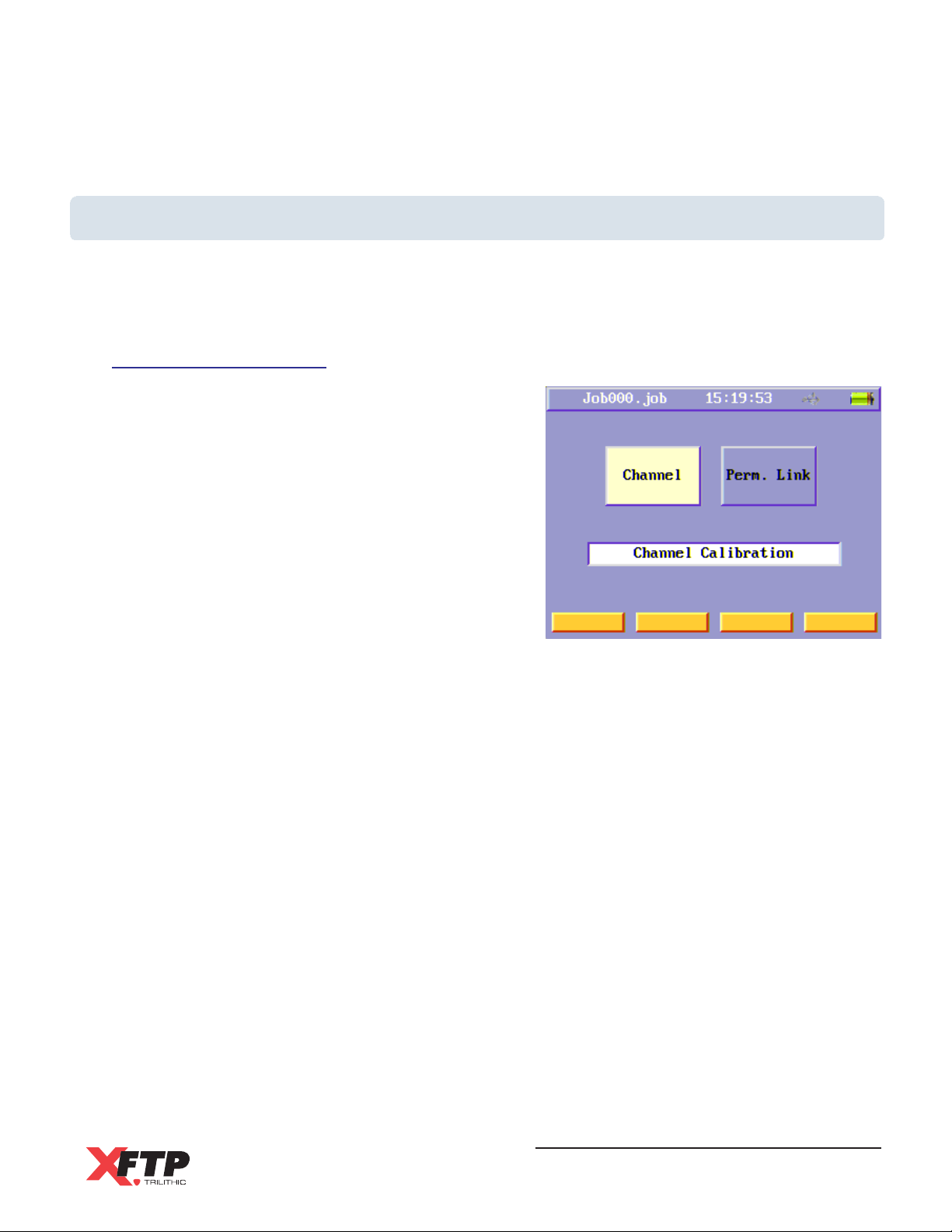
Calibration
The calibration procedure is performed to set a reference for cable testing. After entering the
Calibration menu, two function buttons will be displayed. One is for Channel Calibration, and the
other is for Permanent Link Calibration.
Channel Calibration
For Channel Calibration, do not connect any
equipment cords to the Main Unit or Remote Unit.
To run a channel calibration, use the arrow keys to
highlight the Channel function button and then
press the Enter key.
An Information screen will appear. Press any key to
continue. A message will appear that indicates that
the calibration is in progress.
Once the calibration is complete, press the Enter
key to save the calibration results or press any other
key to exit without saving the results.
A screen will appear to confirm that the calibration has been completed, press any key to
continue.
Wild-Cat Ethernet Cable Tester - Operation Manual
41
Page 44
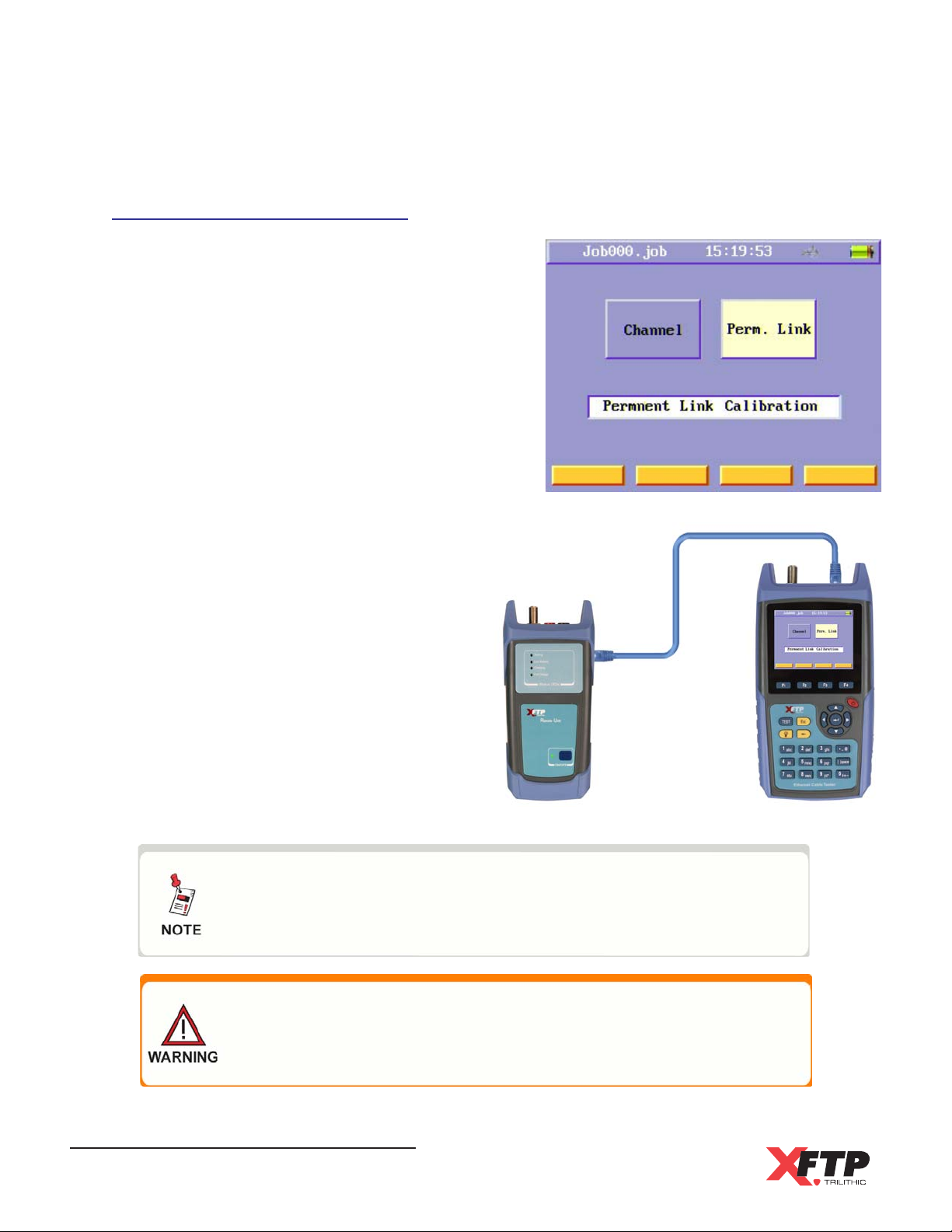
Permanent Link Calibration
To run a Permanent Link Calibration, use the arrow
keys to highlight the Perm Link function button and
then press the Enter key.
Turn on the remote unit and connect the first
equipment cable between the two units, and then
press any key to continue. A message will appear
that indicates that the calibration is in progress.
After the first cable is calibrated, connect the
second cable between the two units and then press
any key to continue. A message will appear that
indicates that the calibration is in progress.
Once the calibration is of both cables is
complete, press the Enter key to save the
calibration results or press any other key to
exit without saving the results.
A screen will appear to confirm that the
calibration has been completed, press any
key to continue.
Before certifying the cabling, do one calibration and do not do
another calibration unless either of the two equipment cables
for testing permanent link need to be changed.
If you do not run a permanent link calibration after you change
the equipment cords, the length result and RF results may be
not correct.
Wild-Cat Ethernet Cable Tester - Operation Manual
42
Page 45
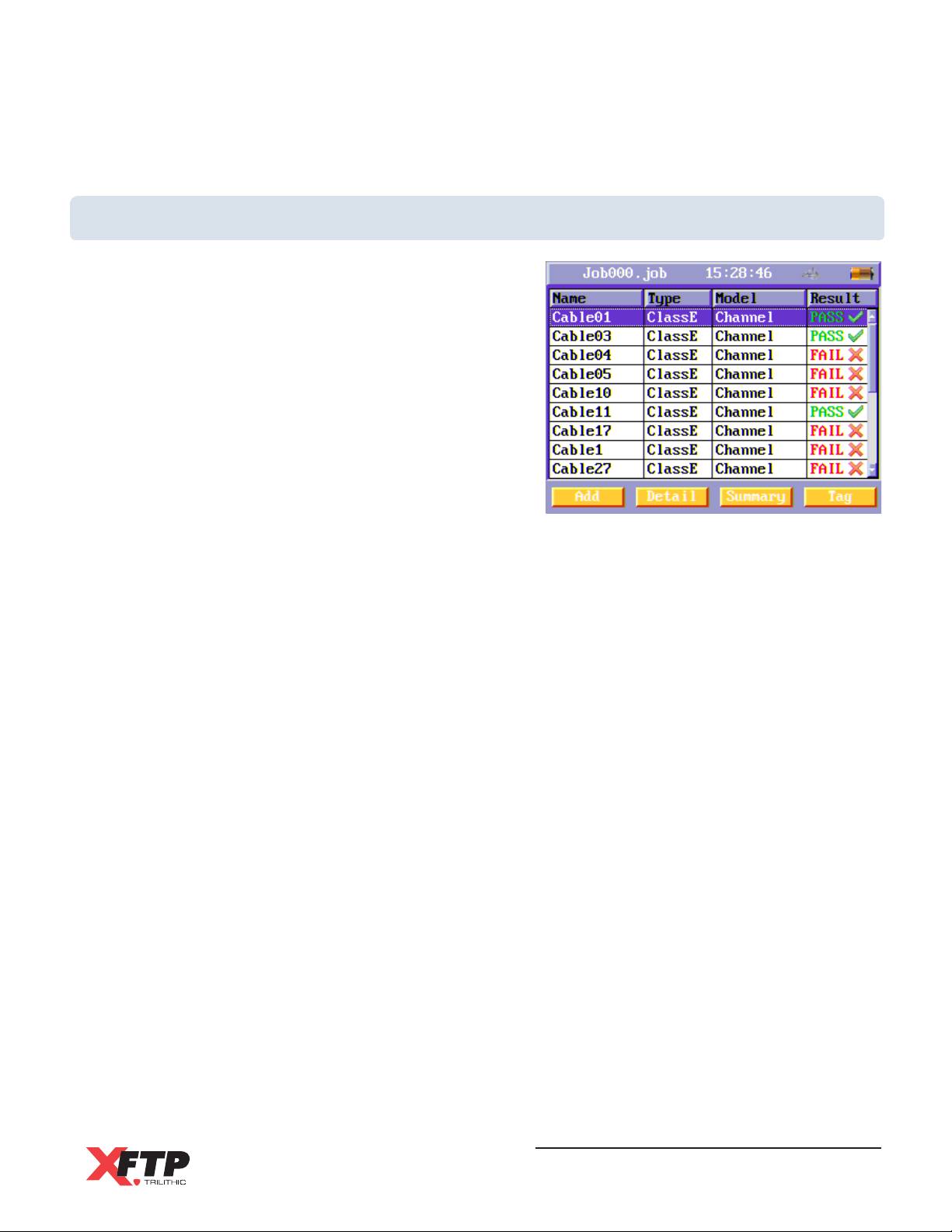
Auto Test
The Auto Test runs a series of tests including the tests
listed below, depending on the selected test limit:
Wire Map
Wire Length
Propagation Delay
Delay Skew
DC Loop Resistance
Insertion Loss (Attenuation)
NEXT (Near-End Crosstalk)
PS NEXT (Power-Sum NEXT)
Return Loss
ACR (Attenuation to Crosstalk Ratio at the Near End)
PS ACR (Power-Sum ACR-N)
ELFEXT (Equal Level Far-End Crosstalk)
PS ELFEXT (Power-Sum ELFEXT)
Wild-Cat Ethernet Cable Tester - Operation Manual
43
Page 46
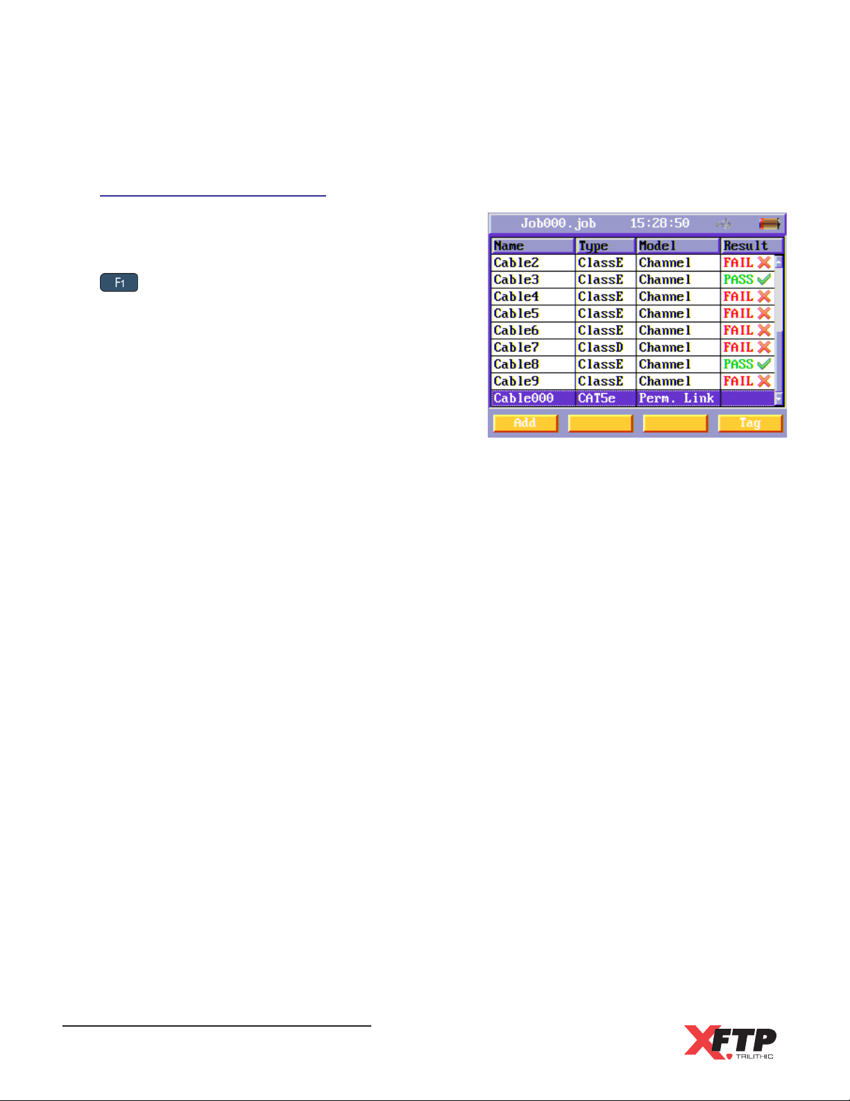
Add a Cable for Testing
In the Auto Test menu, a list of cables in the current
job folder is displayed with their corresponding
Pass/Fail results. To add a new cable, press the
key to select the Add soft function key.
Press the Enter key to edit the properties of the
new cable.
Cable Name
Use the alphanumeric key pad to enter a name
to easily distinguish between cables in the Job
file and then press the Enter key to move to the
next field.
Cable Type
Use the arrow keys to select the type of cable to be tested. The types of cables that are
available are as follows:
Cat3, Cat5e, and Cat6 (UTP/STP) - TIA/EIA-568-B Test Standard
Class C, Class D, Class E (UTP/STP) - ISO/IEC 11801 Test Standard
RG58, RG59, RG6 (Coaxial)
RJ11 (Telephone)
Banana (Banana Jacks)
After selecting the cable type, press the Enter key to move to the next field.
Testing Model
Use the arrow keys to select from Channel or Permanent Link Test Models. After selecting
the Testing Model, press the Enter key to finish making changes to the new cable.
Wild-Cat Ethernet Cable Tester - Operation Manual
44
Page 47
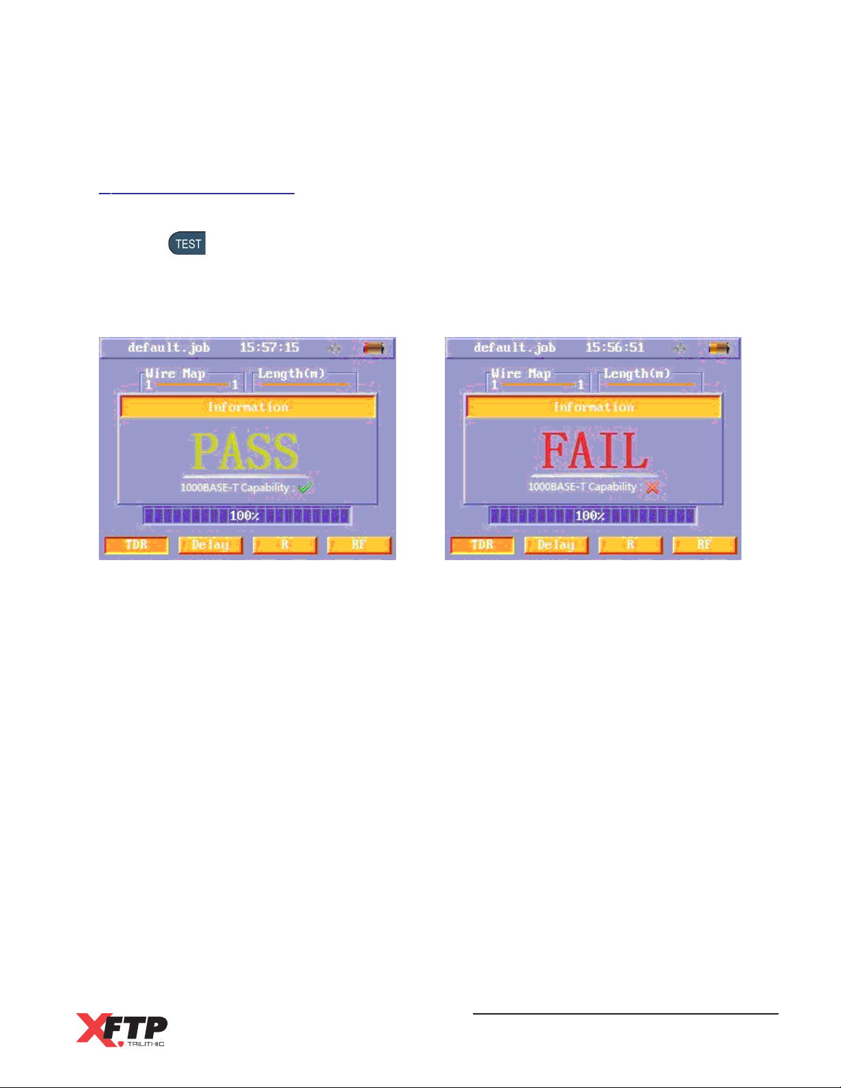
Running an Auto Test
To perform an Auto Test, use the arrow keys to highlight the desired cable to test and then
press the
The Auto Test menu will appear with a progress bar at the bottom of the screen. When the
progress bar shows 100%, the Auto Test has finished and a PASS/FAIL result will appear
briefly.
From the Auto Test menu, the following test results can be viewed by selecting the
corresponding soft function key:
key to start the test.
TDR - Wire map and length
Delay - Propagation Delay and Delay Skew
R - DC Loop Resistance
RF - NEXT, PSNEXT, ELFEXT, PSELFEXT, Return Loss, Insertion Loss, ACR, and
PSACR
After the Auto Test is complete, the detailed results of this cable are saved automatically in the
current job folder.
Wild-Cat Ethernet Cable Tester - Operation Manual
45
Page 48
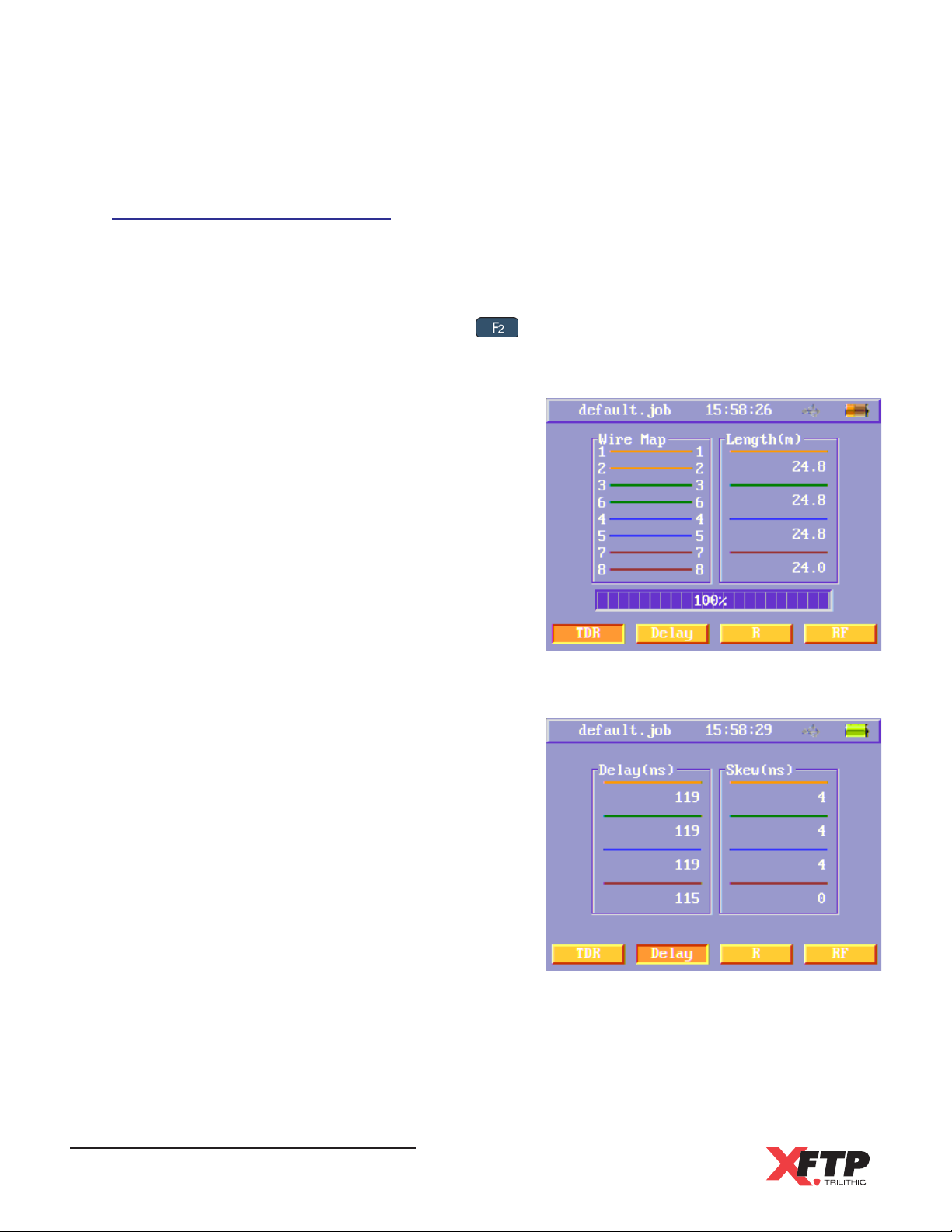
Detailed Auto Test Results
Once the Auto Test has finished, the detailed Auto Test results will be displayed automatically
as shown in the following sections.
To view the detailed Auto Test results for a cable that has already been tested, use the arrow
keys to highlight the cable and then press the
TDR Test Results
This menu displays the Wire Map and Length of
the cables under test.
key to select the Detail soft function key.
Delay Test Results
This menu displays the Propagation Delay and
Delay Skew of the cables under test.
Wild-Cat Ethernet Cable Tester - Operation Manual
46
Page 49
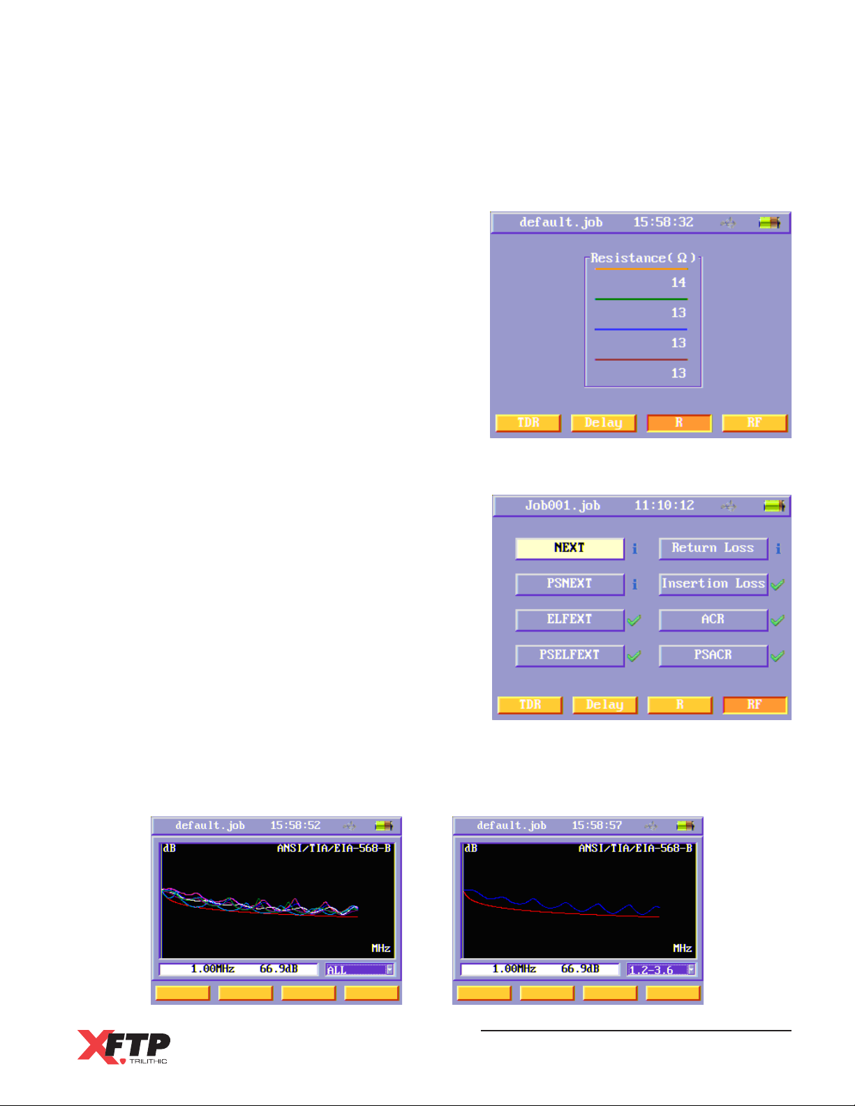
Resistance Test Results
This menu displays the DC Loop Resistance of
the cables under test.
RF Test Results
This menu displays a list of each RF test item in
order to observe the detailed test results for
each RF test.
Use the arrow keys to highlight the desired
function and then press the Enter key to view the
corresponding test results.
The following example shows the NEXT test
results. The frequency and value shown on the
bottom of the menu is the current frequency of
the cursor and the first pairs value.
Use the arrow keys to move the cursor to the
deisred frequency. Press the Enter key to select the wire pairs field and then use the
arrow keys to the select the desired pair. Once the desired pair is highlighted, press the
Enter key again to display the graph.
Wild-Cat Ethernet Cable Tester - Operation Manual
47
Page 50
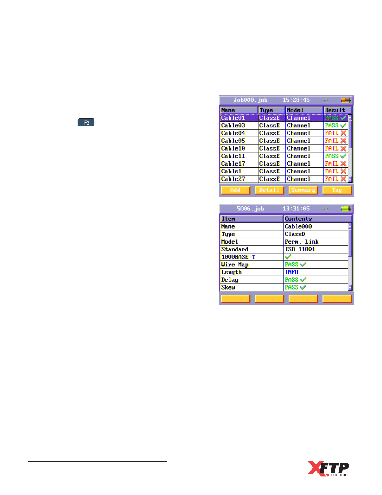
Auto Test Summary
In the Auto Test menu, use the arrow keys to
highlight the desired cable.
Press the key to select the Summary soft
function key. A summary of the Auto Test for the
selected cable will be displayed.
Use the arrow keys to scroll through the Auto Test
summary page.
Wild-Cat Ethernet Cable Tester - Operation Manual
48
Page 51
Delete an Existing Cable
From the Auto Test menu, use the arrow keys to highlight an existing cable and then press the
key to select the Tag soft function key. Repeat this process for all cables that you wish to
delete. To select all cables, press the
Once all the cables to be deleted are tagged, press the key to select the Delete soft
function key. A Warning will appear, press the Enter key to delete the cables or press any
other key to exit without deleting the cables.
key to select the Tag All soft function key.
Transferring a Cable to a USB Flash Drive
Connect a USB Flash drive to the USB Port of the Main Unit
before proceeding with this section.
From the Auto Test menu, use the arrow keys to highlight an existing cable and then press the
key to select the Tag soft function key. Repeat this process for all cables that you wish to
transfer to a USB Flash Drive. To transfer all cables, press the key to select the Tag All
soft function key.
Once all the cables to be transferred are tagged, press the key to select the To Udisk
soft function key. An Information screen will appear, press any key to continue.
Wild-Cat Ethernet Cable Tester - Operation Manual
49
Page 52
Manual Test
The Manual Test includes the following features:
Provides individual cable testing for the same test items found in the Auto Test.
Displays only the test results and does not provide a PASS/FAIL conclusion.
Provides a Throughput Test and TONE Generator that are not included in the Auto Test
functions.
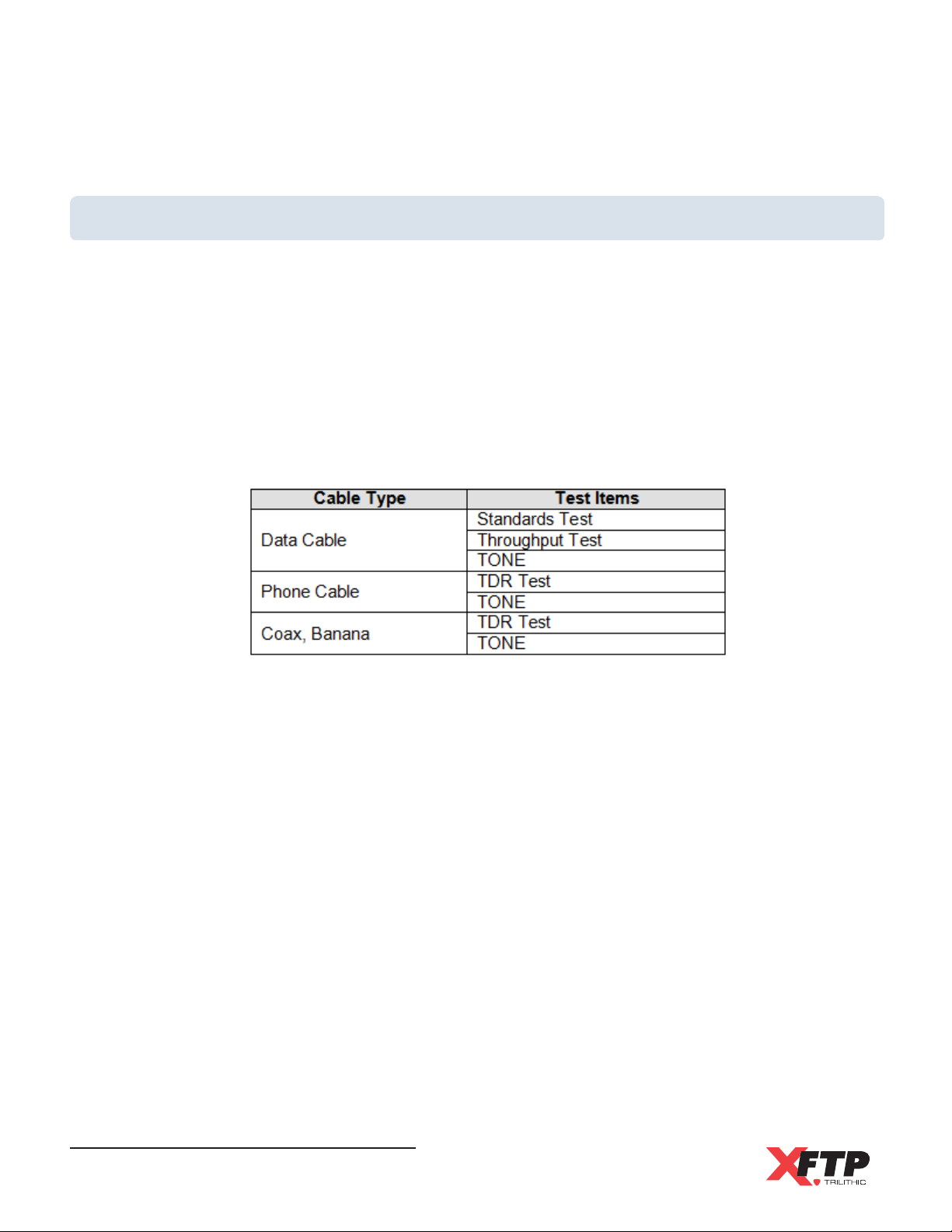
Provides different test items according to the selected cable type. The following table
displays the cable types and their associated test items.
Wild-Cat Ethernet Cable Tester - Operation Manual
50
Page 53
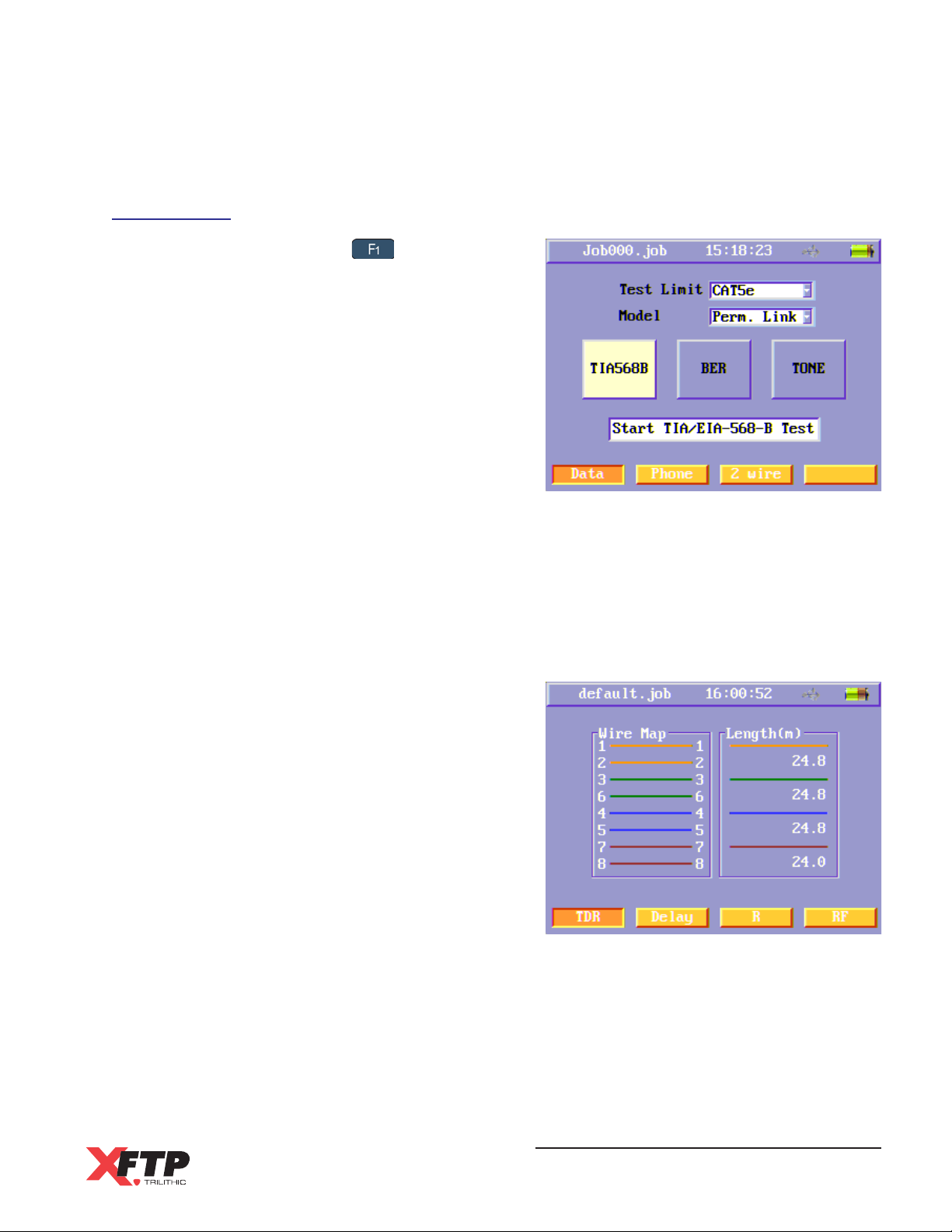
Data Cable
To test data cables, press the key to select
the Data soft function key.
Standards Test
Turn on the Main Unit and the Remote Unit and then connect these two units to each end of
the UTP/STP cable under test.
Before starting a Standards Test, select the Test Limit (Cable Type) and the Test Model
as shown in the Auto Test section earlier in this chapter.
Use the arrow keys to highlight the TIA568B or
ISO11801 (according to the test standard)
button and then select the Enter key to perform
a Standards Test.
After selecting the TIA568B or ISO11801
button, the instrument will perform the Wire Map
and Length tests first and then the TDR Test
menu will appear.
The TDR, Delay, Resistance, and RF menus
will display the test results as shown in the Auto
Test section earlier in this chapter.
Wild-Cat Ethernet Cable Tester - Operation Manual
51
Page 54
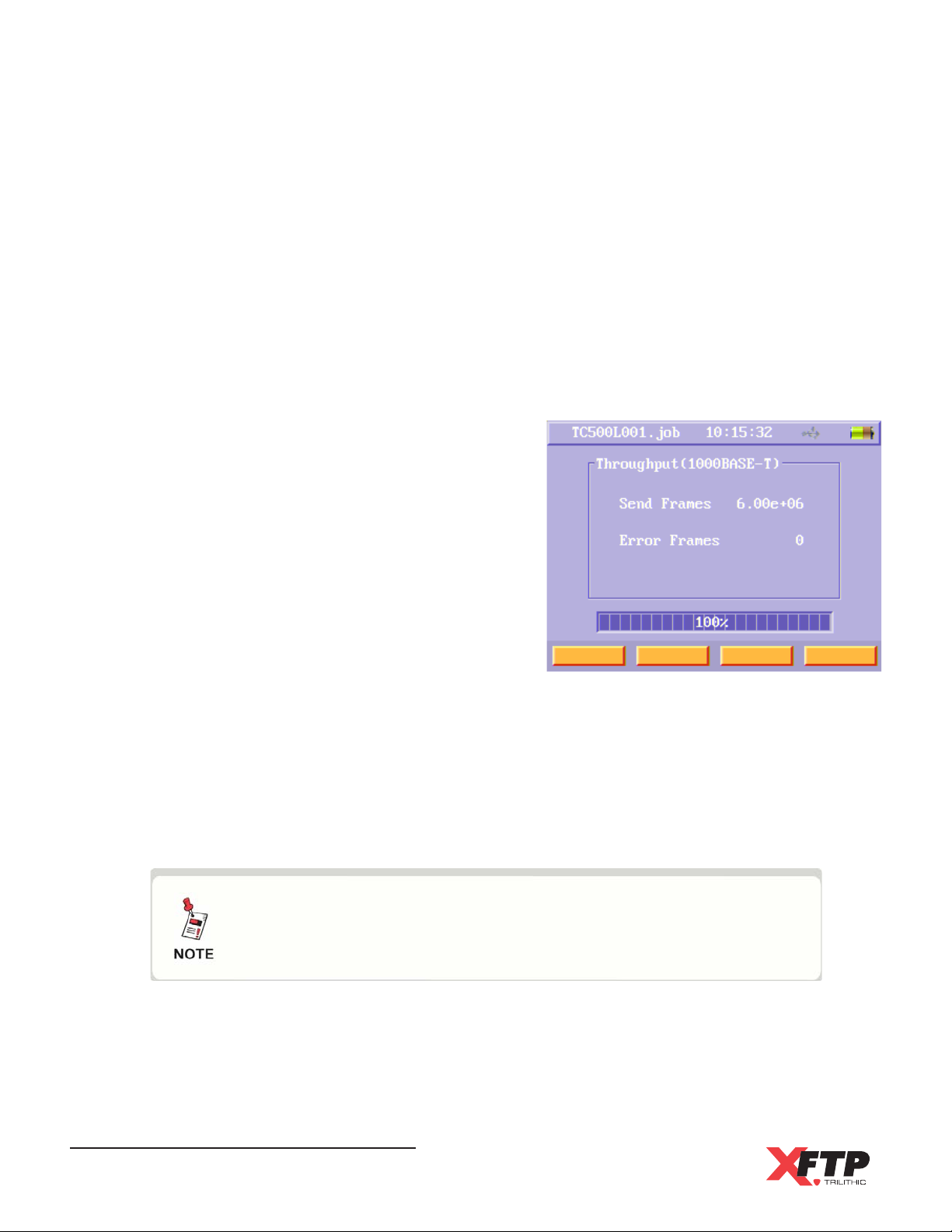
Throughput Test
The Throughput Test is only used for UTP/STP data cables. The Throughput Test can test
on the MAC layer of 10BASE-T, 100BASE-TX, or 1000BASE-T according to IEEE802.3.
Select the test limit and corresponding speed you want to test.
Cat3 & Class C - 10BASE-T
Cat5e & Class D - 100BASE-TX
Cat6 & Class E - 1000BASE-T
Turn on the Main Unit and the Remote Unit and
then connect these two units to each end of the
UTP/STP cable under test.
Before starting a Standards Test, select the Test
Limit (Cable Type) and the Test Model as
shown in the Auto Test section earlier in this
chapter.
Use the arrow keys to highlight the Throughput
function button and then select the Enter key to
perform a Throughput Test.
After selecting the Throughput function button,
the instrument will perform the Throughput Test.
In the Throughput Test menu the following will be displayed:
Sent Frames - This indicates the number of frames sent.
Error Frames - This indicates the number of error frames received.
When the Throughput Test is finished, the progress bar displays 100%.
If the wire map of the data cable under test is not correct, a
message box will display Wire map is in error or the remote
unit does not exist and the Throughput Test will not run.
If the data cable becomes disconnected from the instrument when the Throughput Test is
running, the Main Unit will display the message The remote unit link down. Press any key
to continue.
Wild-Cat Ethernet Cable Tester - Operation Manual
52
Page 55
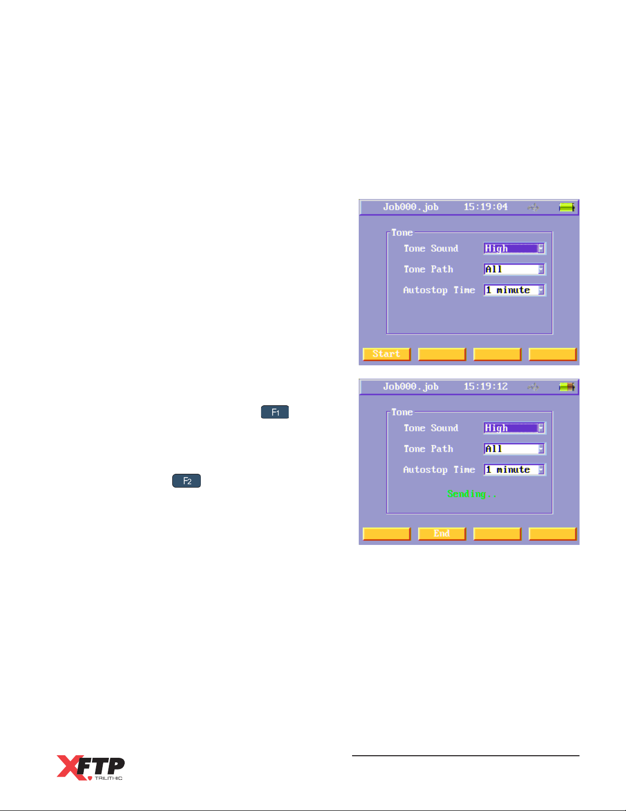
Tone Test
When performing a Tone Test, connect the Main Unit to the cable under test and do not use
the Remote Unit. When running a Tone Test, the main unit sends the Tone Test sound on
the wire pair that is selected.
Use the arrow keys to highlight the following
settings and then press the Enter key to adjust
the settings:
Tone Sound - Select from High or Low
tone setting
Tone Path - Select the wires pairs used
to transmit the Tone
Autostop Time - Select the amount of
time that the Tone will transmit
Press the Enter key after adjusting each setting
to confirm the change.
To start the Tone Test, press the key to
select the Start soft function key.
The Tone Test will continue to transmit until the
Autostop Timer has expired. To stop the Tone
Test, press the key to select the End soft
function key.
Wild-Cat Ethernet Cable Tester - Operation Manual
53
Page 56
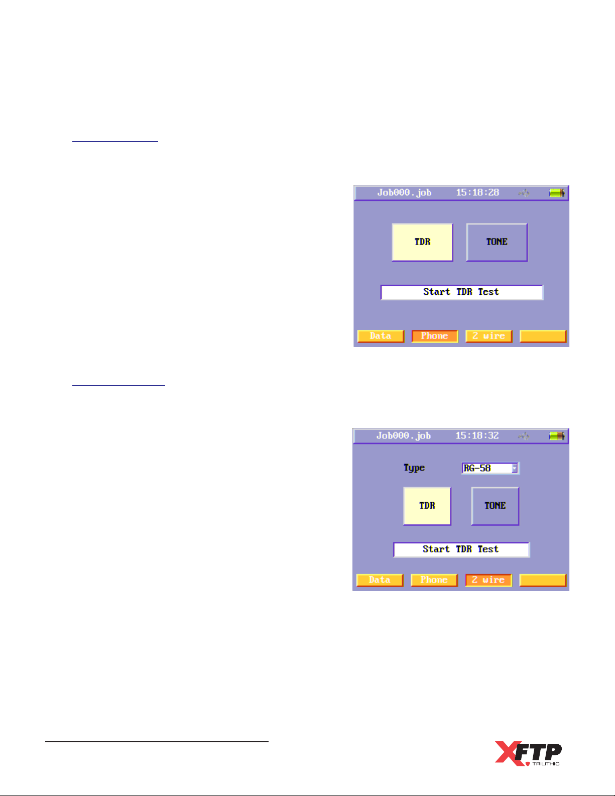
Phone Cable
TDR Test
The TDR menu will display the same test results
shown in the Auto Test section discussed earlier
in this chapter.
Tone Test
See the steps outlined in the previous sections
to perform a Tone Test.
2-Wire Cable
TDR Test
The TDR menu will display the same test results
shown in the Auto Test section discussed earlier
in this chapter.
Tone Test
See the steps outlined in the previous sections
to perform a TONE Test.
Wild-Cat Ethernet Cable Tester - Operation Manual
54
Page 57
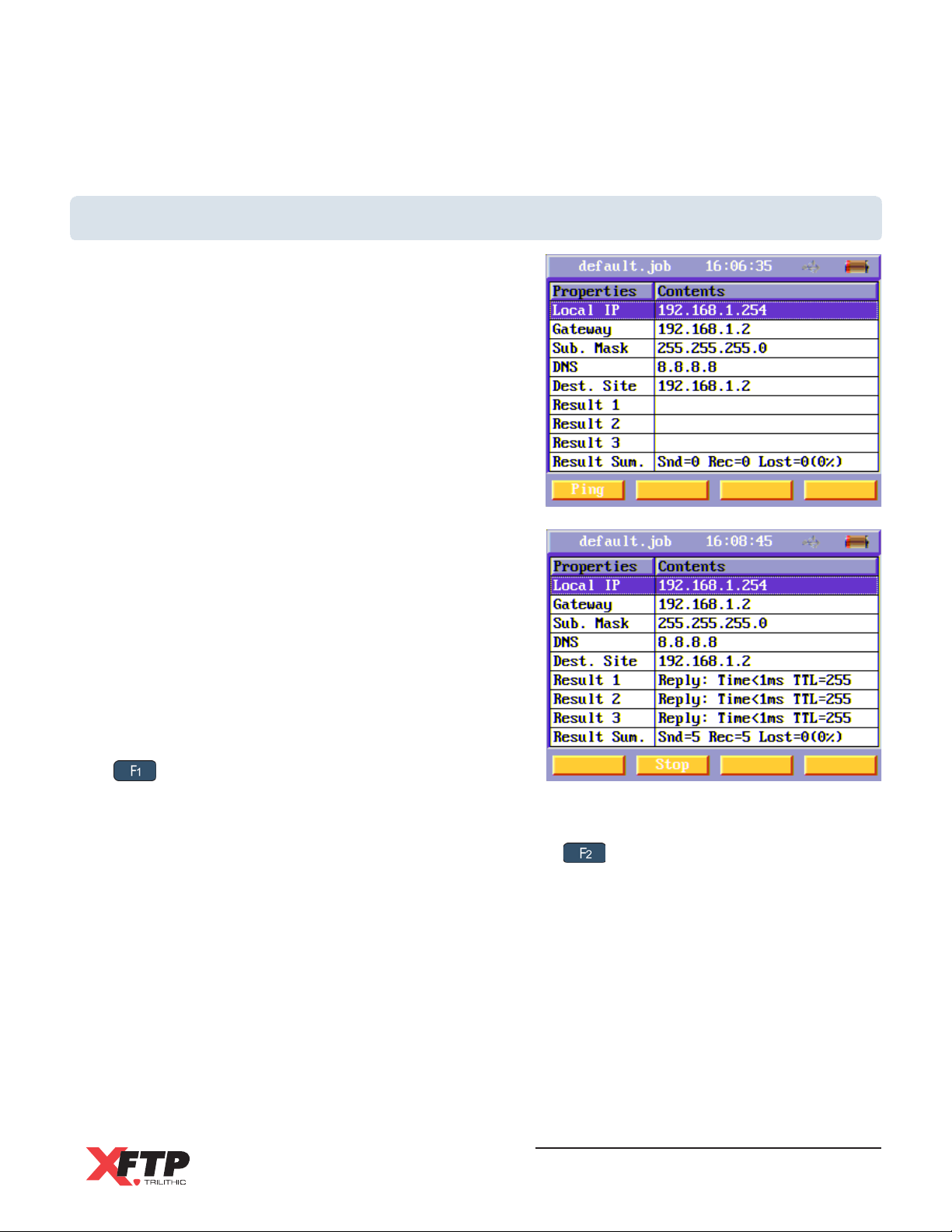
Network Test
The Network Test will Ping the connected network using
the main unit. The ping test verifies connectivity to
devices on the network.
To run a ping test, connect the main unit to the network
using an UTP/STP cable. The Remote unit is not used
in a ping test.
In the Network Test menu, use the arrow keys to
highlight any of the following Ping settings:
Local IP
Gateway
Subnet Mask
DNS
Destination Site
Press the Enter key to edit the highlighted Ping setting
and then use the alphanumeric keypad to adjust the
values. Press the Enter key again to accept the
changes.
Once all the Ping settings have been changed, press
the key to select the Ping soft function key to start
the Ping test.
The Ping test results are shown in the Results and Results Summary rows. The Ping test will
continue to Ping the server. To stop the Ping test, press the key to select the Stop soft
function key.
Wild-Cat Ethernet Cable Tester - Operation Manual
55
Page 58
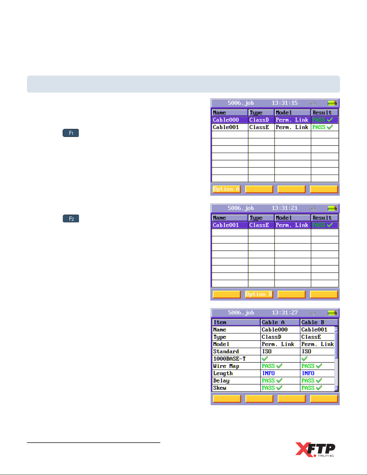
Results Comparison
The Results Comparison menu displays summary
test results for two cables simultaneously.
Use the arrow keys to highlight the first cable, then
press the key to select the Option A soft function
key.
Use the arrow keys to highlight the second cable, then
press the key to select the Option B soft function
key.
The Comparison screen will be displayed. Use the
arrow keys to scroll through the summary results.
Wild-Cat Ethernet Cable Tester - Operation Manual
56
Page 59
6. System Information
Overview
The following sections describes how to view the
system information of the Wild-Cat.
This section assumes you are at least familiar with the
basic operation of the navigational tools used in the
Wild-Cat, so be sure to review Chapter 3:
Walkthrough before proceeding through this section.
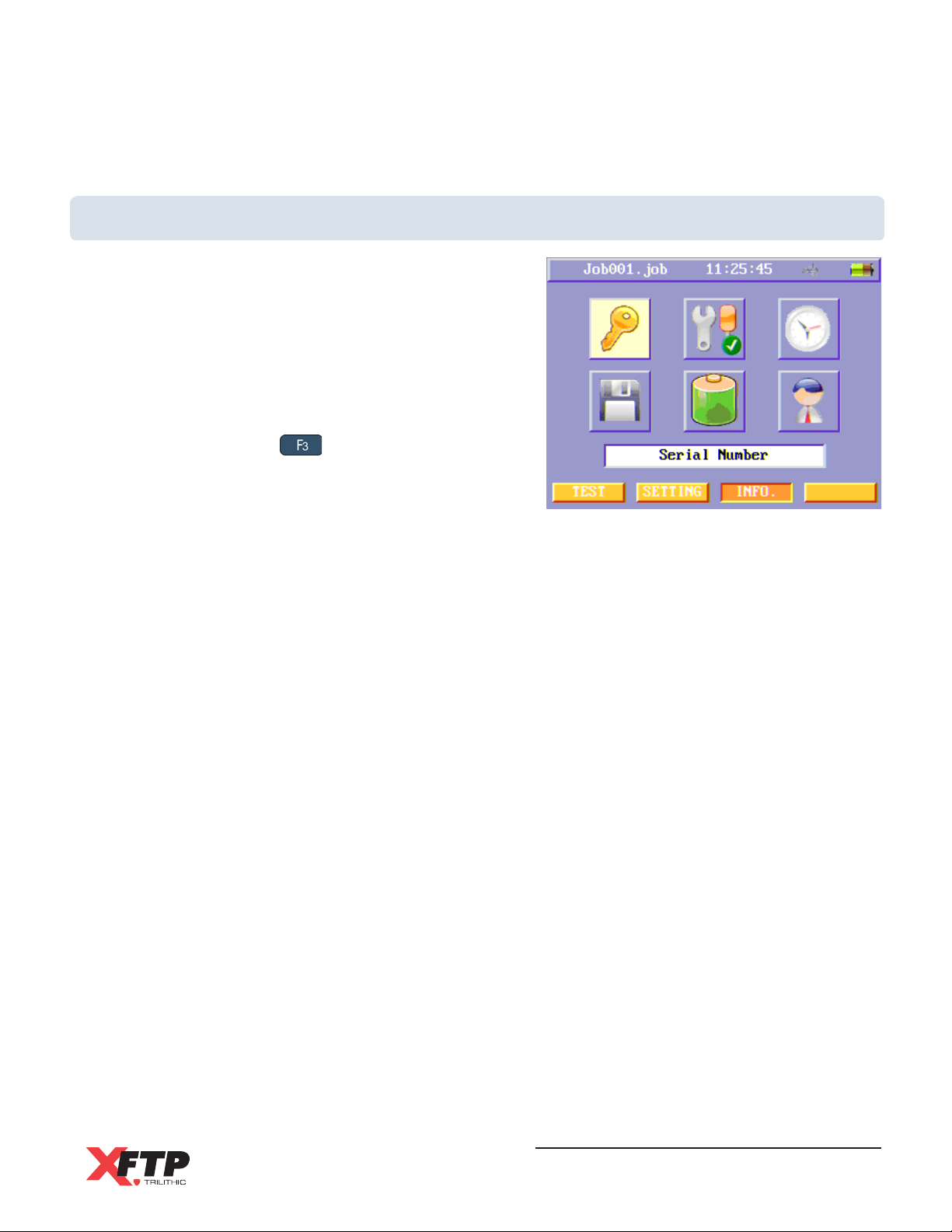
To enter the INFO menu page from the SETTING or
TEST menus, press the key to select the INFO
soft function key.
Chapter 6
Wild-Cat Ethernet Cable Tester - Operation Manual
57
Page 60
Info Menu Icons
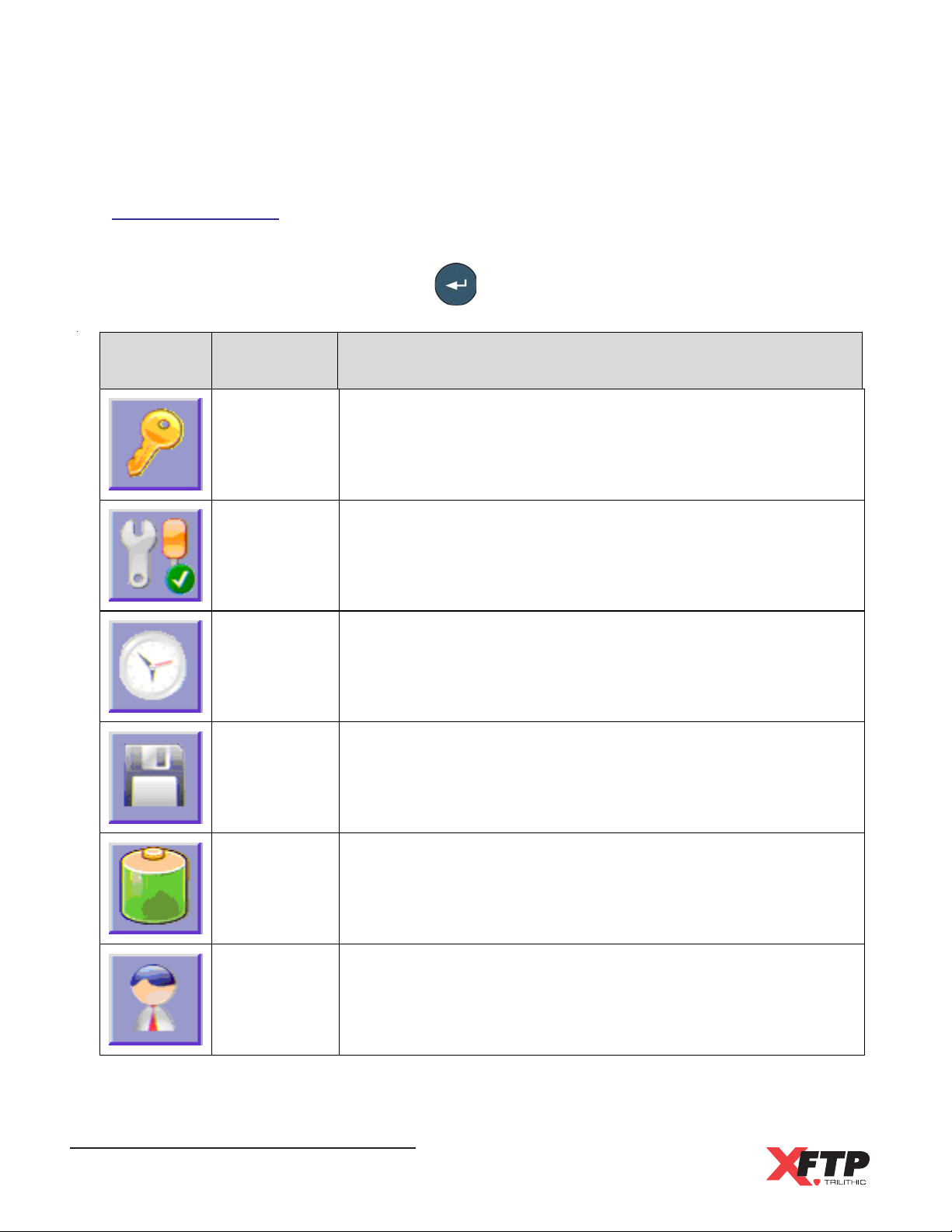
The following functions are available from the Info menu. Use the arrow keys to highlight the
desired function icon and then press the key to enter the corresponding function.
Icon Function Purpose
Serial
Number
Previous
Calibration
Date
Time & Date This is used to view the current date and time
Remaining
Memory
Battery
Information
This is used to view the serial number, kernel version,
software version, and firmware version of t he tester
This is used to view the previous calibration date
This is used to view the percentage of remaining free
memory
This is used to view the percentage of battery charge that
remains
Support
Information
Wild-Cat Ethernet Cable Tester - Operation Manual
58
This is used to view contact and support information
Page 61
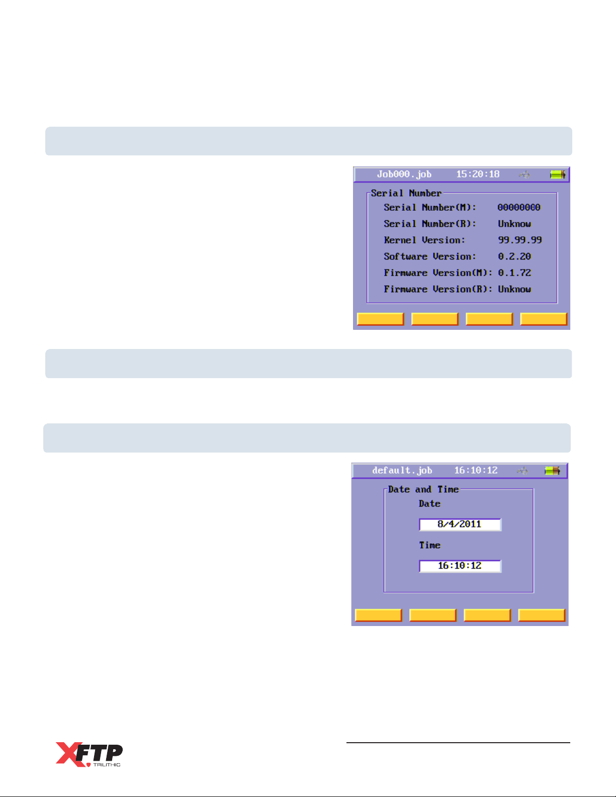
Serial Number
This menu displays the serial number and the version
levels of the OS Kernel, Software, and Firmware.
Previous Calibration Date
This menu displays the last calibration date. If the same equipment cords are used for certifying
every permanent link cable installation, calibrate the instrument every 30 days.
Time and Date
This menu shows the current date and time.
Wild-Cat Ethernet Cable Tester - Operation Manual
59
Page 62
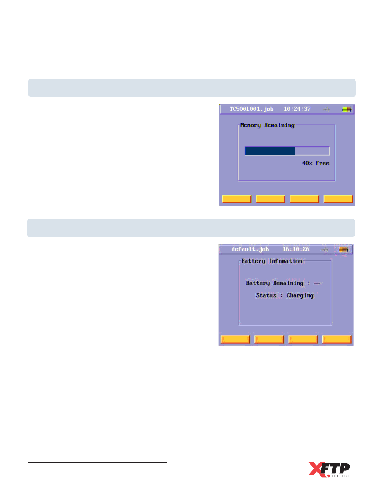
Remaining Memory
This menu shows the remaining memory that can be
used to save configuration and measurement files.
Battery Information
This menu displays the charging status and remaining
battery charge in the Main Unit.
Wild-Cat Ethernet Cable Tester - Operation Manual
60
Page 63
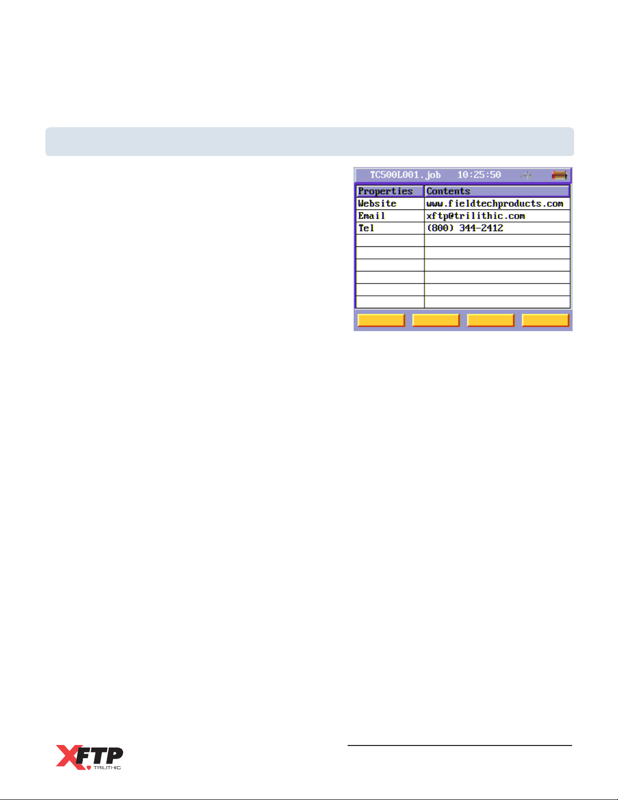
Support Information
This menu displays Technical Support contact
information, including the XFTP web site, email
address, and telephone number.
Wild-Cat Ethernet Cable Tester - Operation Manual
61
Page 64

THIS PAGE LEFT INTENTIONALLY BLANK
Wild-Cat Ethernet Cable Tester - Operation Manual
62
Page 65

Chapter 7
7. ToolBox Software
Overview
The Wild-Cat ToolBox software is used for in-depth analysis of measurement results from the
Wild-Cat Ethernet Cable Tester and has the following features:
View Inspector & Site Information
View Wire Map & Length Test Results
View Delay, Skew, and Resistance Test Results
View 1000Base-T Capabilities
View RF Test Charts for Insertion Loss, NEXT, PSNEXT, ELFEXT, PSELFEXT, and Return
Loss
Print Detailed Test Reports
Installing the Wild-Cat ToolBox Software
This section describes how to install the Wild-Cat ToolBox Software.
Requirements
To operate the Wild-Cat ToolBox software, you need to meet the following minimum
requirements:
200 MHz Pentium-II
64 MB RAM
100 MB free disk space
Color monitor running at 256 colors or higher, 1024 x 768 screen resolution
Windows compatible mouse
Wild-Cat Ethernet Cable Tester - Operation Manual
63
Page 66
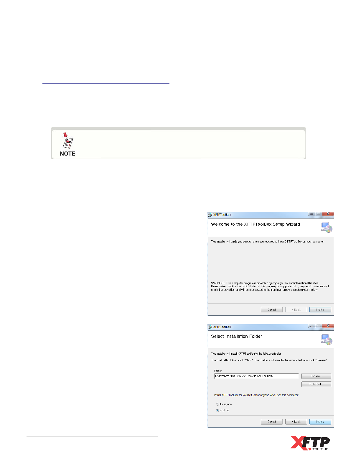
Installing the Wild-Cat ToolBox
Once you have made sure that your system meets the minimum requirements, youre ready to
install the Wild-Cat ToolBox software.
To install the Wild-Cat ToolBox software, perform the following steps:
NOTE: Be sure to check the CD for release notes that may affect
the installation and configuration process!
1. Depending on the operating system you are installing the Wild-Cat ToolBox software
on, you may need to log on as the local administrator. (Check with your network or
systems administrator if youre not sure about your current login account permissions.)
2. Insert the ToolBox software CD in the appropriate drive.
3. If you have Autorun enabled for the CD-ROM
drive, the Wild-Cat ToolBox software setup
program will start automatically. Otherwise,
click Start, then click Run, and type
[drive]:\setup.exe, then click OK. (Substitute
the appropriate drive path in the command.)
The Setup program starts and displays the
Welcome to the XFTPToolBox Setup Wizard
screen.
4. The Select Installation Folder screen
appears, click the Next button.
Wild-Cat Ethernet Cable Tester - Operation Manual
64
Page 67
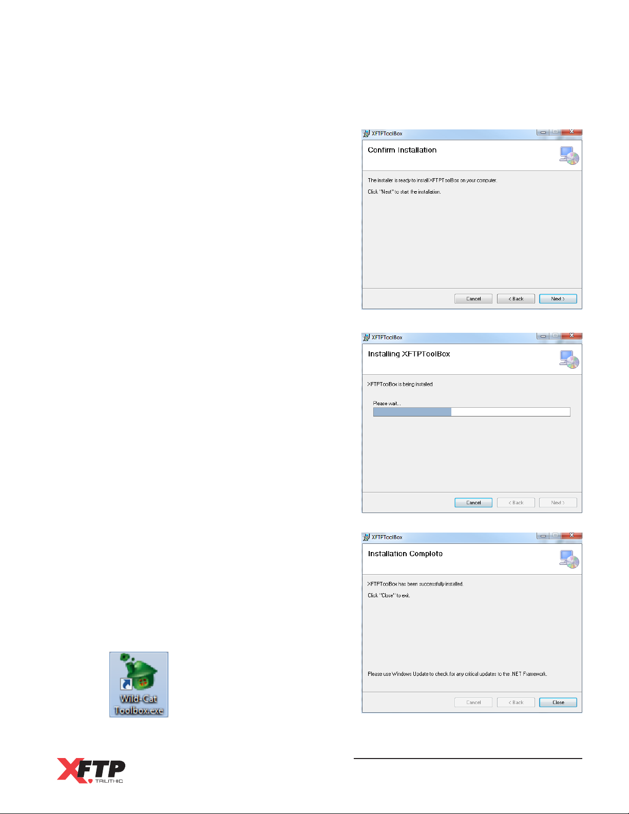
5. The Confirm Installation screen appears,
click the Next button.
6. The software will begin the installation
process. The software installs the files and
installs the Trilithic Wild-Cat ToolBox icon on
your desktop. While the software is being
installed, a screen appears that shows the
progress of the installation. (The entire
installation process should only take a
minute or two at most.)
7. When the Wild-Cat ToolBox software has
been installed on your system, the Installation
Complete screen appears. Click the Close
button.
8. This completes the Trilithic Wild-Cat ToolBox
installation procedure. The Wild-Cat ToolBox
icon now appears on the desktop.
Wild-Cat Ethernet Cable Tester - Operation Manual
65
Page 68
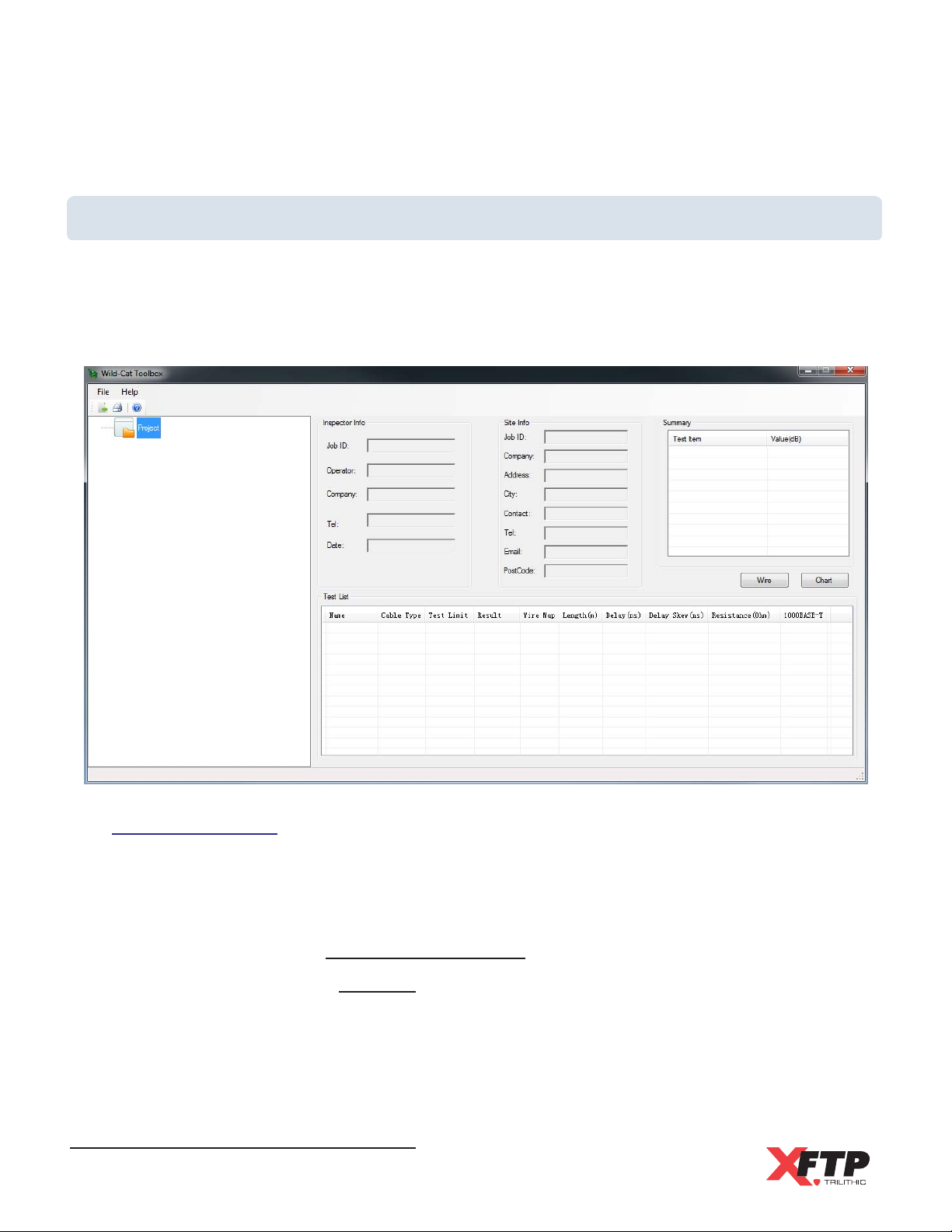
Learning Your Way Around
Wild-Cat ToolBox requires virtually no configuration. So once you have installed the Wild-Cat
ToolBox software, youre ready to learn your way around. Start Wild-Cat ToolBox by doubleclicking the Trilithic Wild-Cat ToolBox icon on your desktop. After a moment, the main Wild-Cat
ToolBox screen appears.
Before Starting
To view job information or measurement results using the ToolBox software, you will need to
first transfer these files from the Wild-Cat to a USB flash drive.
See the following sections for more information about transferring files to a USB flash drive:
Chapter 4: Setup, Job Information Settings, Transferring a Job to a USB Flash Drive
Chapter 5: Testing, Auto Test, Transferring a Cable to a USB Flash Drive
Once the files have been transferred to the USB flash drive, they will be stored in the following
folder: <Drive Letter>:\Wild-Cat\Data\<Job Name>.
Wild-Cat Ethernet Cable Tester - Operation Manual
66
Page 69
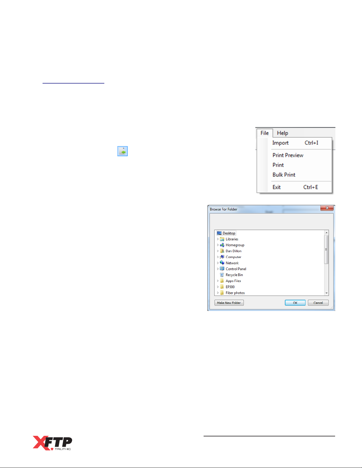
Importing Files
To import files into the ToolBox software, perform the following steps:
1. Insert the USB flash drive with the job information and/or measurement result files into
an available USB port on the PC that the ToolBox software is installed on.
2. There are three ways to import files into the ToolBox
software:
Select the icon from the toolbar.
Select File > Import from the menu bar as shown in
the image to the right.
Press the Ctrl+I keys at the same time.
3. The Browse For Folder window will open.
Navigate to the location of the measurement
files on the USB flash drive and then select
the OK button.
4. The measurement data will be displayed in
the main window as shown in the following
section.
Wild-Cat Ethernet Cable Tester - Operation Manual
67
Page 70
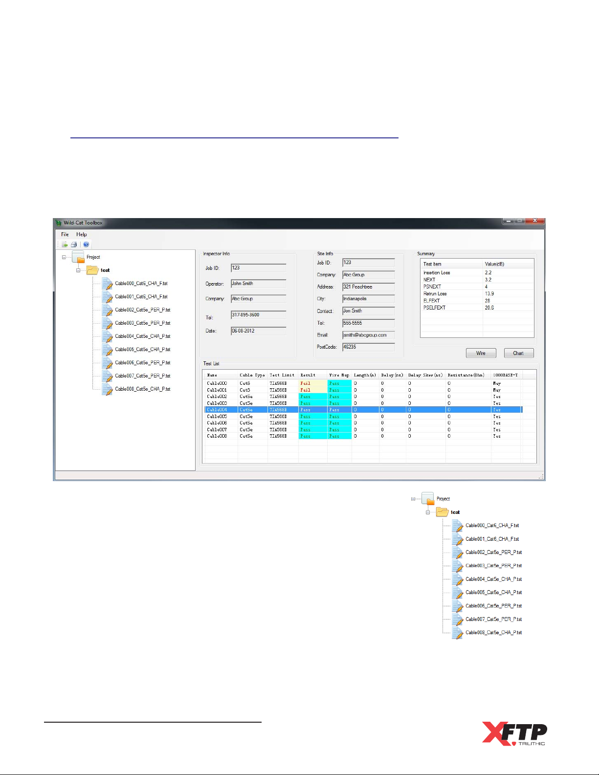
Viewing Job Information & Measurement Results
After importing the measurement files from a USB flash drive, the main screen is populated
with the job information and measurement results as shown inf the following image. To view the
results of a specific test, use the mouse to select the desired cable from the Test List area of
the screen.
Import Path
The import path area of the main screen displays the
selected import directory and all of the measurement files
that were found as shown in the image to the right.
The Project folder contains all of the jobs that were located in
the import folder. The individual tests that belong to the
imported job appear as test files within that folder.
Wild-Cat Ethernet Cable Tester - Operation Manual
68
Page 71
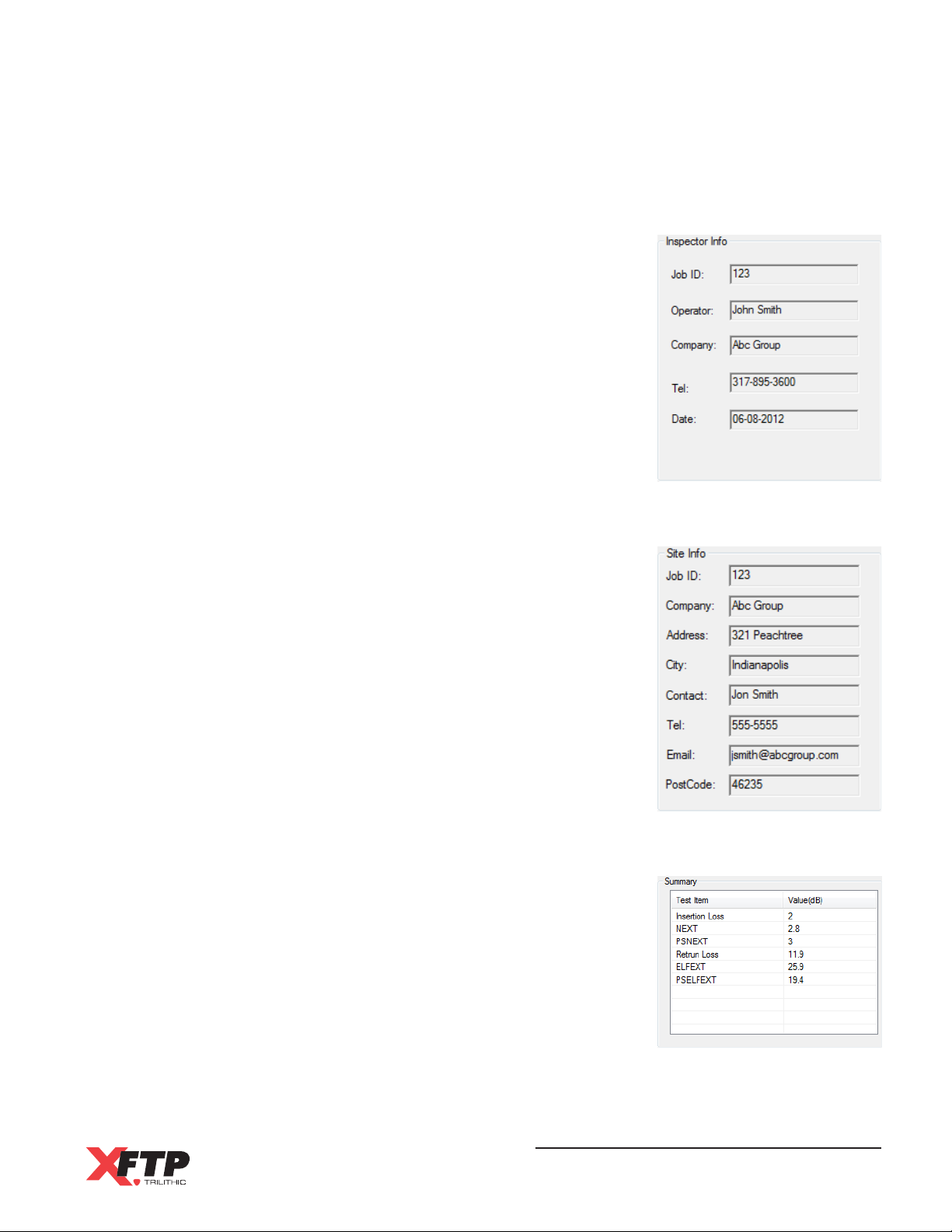
Inspector Info
The Inspector Info area of the main screen displays the Job ID,
Operator, Company, Telephone, and Date of the selected job
as shown in image to the right.
Site Info
The Inspector Info area of the main screen displays the Job ID,
Company, Address, City, Contact, Telephone, Email and
Postal Code of the selected job as shown in image to the
right.
Summary
The Summary area of the main screen displays the test
summary of the selected cable as shown in image to the right.
Wild-Cat Ethernet Cable Tester - Operation Manual
69
Page 72
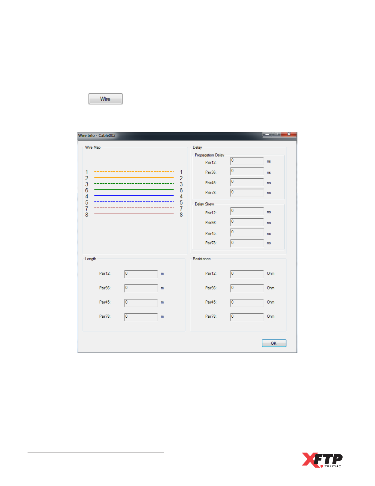
Wire Map
Select the button to view the wire map which also includes length, delay, and
resistance measurements of the selected cable as shown in image below. When you are
done reviewing the measurement results, select the OK button to exit this screen.
Wild-Cat Ethernet Cable Tester - Operation Manual
70
Page 73
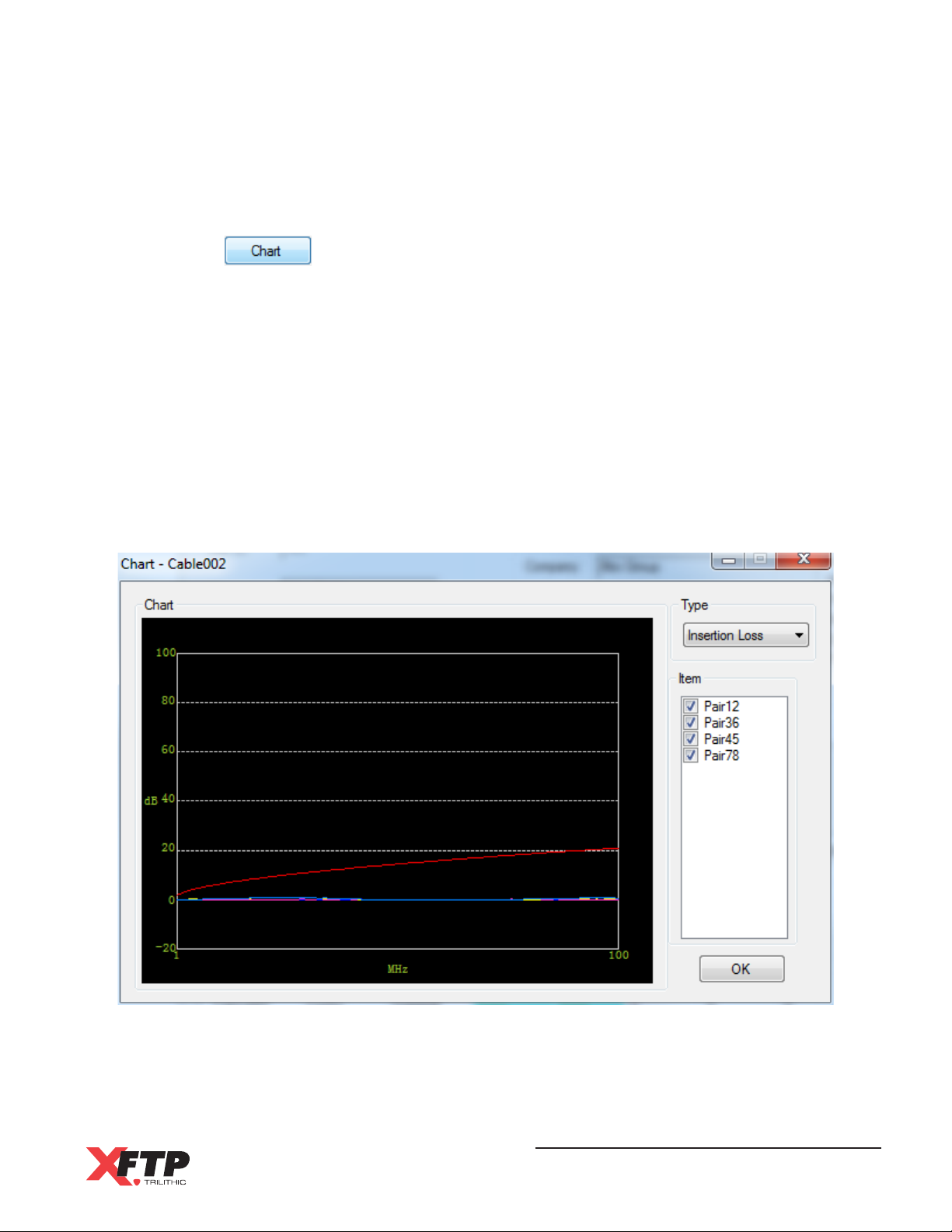
Wire Map
Select the button to view the RF test results which includes measurements of
the selected cable as shown in image below.
Use the Type dropdown menu to select from the Insertion Loss, NEXT, PSNEXT, ELFEXT,
PSELFEXT, or Return Loss measurements.
When viewing the test results, all items tested will appear by default. To view/hide specific
items, select/deselect the checkbox next to the desired items. Each item tested is
represented by a unique line color on the chart with the red line representing the selected
test standard.
When you are done reviewing the measurement results, select the OK button to exit this
screen.
Wild-Cat Ethernet Cable Tester - Operation Manual
71
Page 74
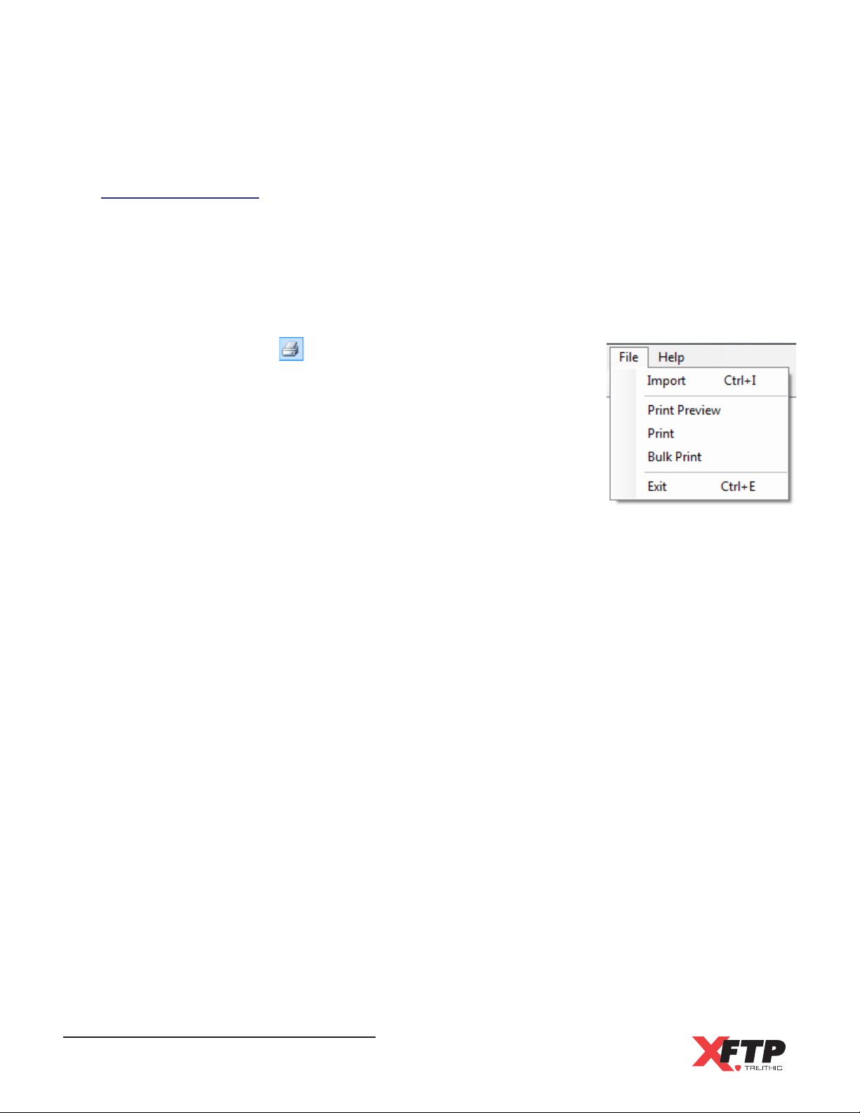
Printing Reports
To print reports from the ToolBox software, perform the following steps:
1. Use the mouse to select the desired cable from the Test List area of the screen.
2. Select File > Print Preview from the menu bar to preview the report before printing.
3. There are three ways to print reports from the ToolBox software:
Select the icon from the toolbar to print a report
for only the selected cable.
Select File > Print from the menu bar as shown in the
image to the right to print a report for only the
selected cable.
Select File > Bulk Print from the menu bar as shown
in the image to the right to print reports for all of the
cables in the currently selected job.
Wild-Cat Ethernet Cable Tester - Operation Manual
72
Page 75

Specifications
Length
Range: 0 to 176 m (UTP), 0 to 200 m (Coax)
Resolution: 0.1 m
Accuracy: ±1.5 m
Propagation Delay
Range: 0 to 850 ns
Resolution: 1 ns
Chapter 8
8. Appendix
Accuracy: ±7 ns
Delay Skew
Range: 0 to 100 ns
Resolution: 1 ns
Accuracy: ±15 ns
DC Resistance
Range: 0 - 100 Ohms
Resolution: 1 Ohm
Accuracy: ±2 Ohms
RF Frequency
Range: 1 to 250 MHz
Resolution/Accuracy:
1 to 31.25 MHz: 150 kHz (NEXT, Return Loss, ELFEXT)
1 to 250 MHz: 1 MHz (Insertion Loss)
31.25 to 100 MHz: 250kHz
100 to 250 MHz: 500 kHz
Wild-Cat Ethernet Cable Tester - Operation Manual
73
Page 76

RF Items
Range: 0 - 70dB(NEXT), 0-40dB(Insertion Loss)
Resolution: 0.1dB
Accuracy: ±2dB (Insertion Loss)
Auto Tests
Wire Map, Length, Propagation Delay, Delay Skew, DC Loop Resistance, Insertion Loss,
NEXT, PS NEXT, Return Loss, ACR, PS ACR, ELFEXT, PS ELFEXT, Open/Short Distance,
Test Channel and Permanent Llink
Manual Tests
Single Auto Test Item, 10/100/1000 BASE-T, Throughput Test, and TONE
Network Tests
Ping
Display
3.5inch 16M Color LCD
Weight
Main Unit: 1.64 lbs (0.790 Kg)
Remote Unit: 0.76 lbs (0.345 Kg)
Dimensions
Main Unit (H x W x D): 8.75 x 4.25 x 2.25 in (222 x 108 x 57 mm)
Remote Unit (H x W x D): 7.25 x 3.25 x 1.75 in (184 x 83 x 44 mm)
Wild-Cat Ethernet Cable Tester - Operation Manual
74
Page 77

THIS PAGE LEFT INTENTIONALLY BLANK
Wild-Cat Ethernet Cable Tester - Operation Manual
75
Page 78

Warranty Information
Trilithic, Inc. warrants that each part of this product will be free from defects in materials and
workmanship, under normal use, operating conditions and service for a period of one (1) year
from date of delivery. Trilithic, Inc.s obligation under this Warranty shall be limited, at Trilithic,
Inc.s sole option, to replacing the product, or to replacing or repairing any defective part, F.O.B.
Indianapolis, Indiana; provided that the Buyer shall give Trilithic, Inc. written notice.
Batteries are not included or covered by this Warranty.
The remedy set forth herein shall be the only remedy available to the Buyer under this Warranty
and in no event shall Trilithic, Inc. be liable for incidental or consequential damages for any alleged
breach of this Warranty. This Warranty shall not apply to any part of the product which, without fault
of Trilithic, Inc., has been subject to alteration, failure caused by a part not supplied by Trilithic, Inc.,
accident, fire or other casualty, negligence or misuse, or to any cause whatsoever other than as a
result of a defect.
Except for the warranty and exclusions set forth above, and the warranties, if any, available to the
Buyer from those who supply Trilithic, Inc., there are no warranties, expressed or implied (including
without limitation, any implied warranties of merchantability of fitness), with respect to the
condition of the product or its suitability for any use intended for it by the Buyer or by the purchaser
from the Buyer.
Wild-Cat Ethernet Cable Tester - Operation Manual
76
Page 79

Page 80

9710 Park Davis Drive
Indianapolis, IN 46235
(317) 895-3600
www.fieldtechproducts.com
P/N 0010341000 06/12 Made in U.S.A.
 Loading...