

Page 1

XES 8855 Printer
User Guide
701P92414 November 2000
Page 2

EMC Notices
Australia/New Zealand
Changes or modifications to this equipment not specifically approved by Fuji
Xerox Australia Pty. Limited may void the user’s authority to operate this
equipment.
Shielded cables must be used with this equipment to maintain compliance with
the Radiocommunications Act 1992.
European Union
WARNING
This is a Class A product. In a domestic environment this product may
cause radio interference in which case the user may be required to take
adequate measures.
Changes or modifications to this equipment not specifically approved by Xerox
Europe may void the user’s authority to operate this equipment.
Shielded cables must be used with this equipment to maintain compliance with
the EMC Directive (89/336/EEC).
Canada
This Class "A" digital apparatus complies with Canadian ICES-0003.
Cet appareil numérique de la classe "A" est conforme à la norme NMB-003 du
Canada.
WARNING
In order to allow this equipment to operate in proximity to Industrial,
Scientific and Medical (ISM) equipment, the external radiation from ISM
equipment may have to be limited or special mitigation measures taken.
Page 3

EMC Notices (continued)
Japan
This is a Class A product based on the standard of the Voluntary Control
Council for Interference by Information Technology Equipment (VCCI). If this
equipment is used in a domestic environment, radio disturbance may arise.
When such trouble occurs, the user may be required to take corrective
actions.
Changes or modifications to this equipment not specifically approved by Fuji
Xerox Limited may void the user’s authority to operate this equipment.
Shielded cables must be used with this equipment to maintain compliance with
the Voluntary Control Council for Interference by Information Technology
Equipment regulations.
USA
This equipment has been tested and found to comply with the limits for a Class
A digital device, pursuant to Part 15 of the FCC Rules. These limits are
designed to provide reasonable protection against harmful interference when
the equipment is operated in a commercial environment. This equipment
generates, uses, and can radiate radio frequency energy and, if not installed
and used in accordance with the instruction manual, may cause harmful
interference to radio communications. Operation of this equipment in a
residential area is likely to cause harmful interference in which case the user
will be required to correct the interference at his own expense.
Changes or modifications to this equipment not specifically approved by the
Xerox Corporation may void the user’s authority to operate this equipment.
Shielded cables must be used with this equipment to maintain compliance with
FCC regulations.
Page 4

T rademark Acknowledgment s
XEROX®, 8825, XES Synergix 8825 Digital Solution, 8830, XES Synergix
8830 Digital Solution, 8855, XES Synergix 8855 Digital Solution, Synergix
Scan Digital Solution, the digital box icon, AccXES, and acronym, XES are
trademarks of XEROX CORPORATION.
Internet Explorer is a copyright protected program of Microsoft Corporation.
Netscape is a registered trademark of Netscape Communications Corporation.
Page 5

Safety Notes
Your XES Synergix 8825/8830/8855 Digital Solution has been designed and
tested to meet strict safety requirements. These include safety agency
examination and approval plus compliance with established environmental
standards.
Please read the following instructions carefully before operating the XES
Synergix 8825/8830/8855 Digital Solution and refer to them as needed to
ensure continued safe operation.
Follow all warnings and instructions marked on or supplied with the product.
Unplug the units from the wall outlet before cleaning the exterior. Always use
materials specifically designated for the XES Synergix 8825/8830/8855 Digital
Solution. Use of other materials may result in poor performance and could
create a hazardous situation.
Do not use aerosol cleaners. Follow the instructions in this operator manual
for the proper cleaning methods.
Never use supplies or cleaning materials for purposes other than what they
were intended. Keep all supplies and materials out of the reach of children.
Do not use the units near water, wet locations, or outdoors.
The components of this product are equipped with a three-wire, groundingtype plug (i.e., a plug having a grounding pin). This plug will only fit into a
grounding-type power outlet. This is a safety feature. To avoid the risk of
electric shock, contact your electrician to replace the receptacle if you are
unable to insert the plug into the outlet.
Never use a ground adapter plug to connect the system to a power source that
lacks a ground connection terminal.
This system should be operated from the type of power source indicated on
the marking label. If you are not sure of the type of power available, consult
your local power company.
The power supply cord is the disconnect device for this equipment. Make sure
that the installation is near the socket outlet and is easily accessible.
Do not allow anything to rest on the power cord. Do not locate the units where
someone will step on the cord.
Page 6

Safety notes (continued)
Unplug the reprographic system from the wall outlet and refer servicing to
qualified service personnel under the following conditions:
The units should not be placed in a built-in installation unless proper ventilation
is provided.
Never push objects of any kind into the slots of the units as they may touch
dangerous voltage points or short out parts that could result in a risk of fire or
electric shock.
Never spill liquid of any kind on the units.
Never remove any covers or guards that require a tool for removal. There are
no operator serviceable areas within these covers.
Never attempt any maintenance function that is not specified in this operator
manual.
Never defeat interlock switches. Machines are designed to prevent operator
access to unsafe areas. Covers, guards, and interlock switches are provided
to ensure that the system will not operate with the covers opened.
When the power cord is damaged or frayed.
If liquid has been spilled into the product.
If the units have been exposed to rain or water.
If the units are producing unusual noises or odors.
If the units or the cabinets have been damaged.
If you need additional safety information concerning the XES Synergix
8825/8830/8855 or XES supplied materials, you may call:
Within the United States:
1-800-828-6571 toll free.
In other countries:
Please call your local Xerox Engineering Digital Solutions service office for
help.
Local Phone Number______________________________________
Page 7

TABLE OF CONTENTS
SAFETY NOTES................................................................. 2
PRINTER OVERVIEW........................................................ 5
Front View........................................................................ 5
Rear View......................................................................... 6
Right Side View................................................................ 7
MEDIA INFORMATION....................................................... 9
Loading the Media - Rolls 1, 2, 3..................................... 9
Loading the Media - Roll 4............................................ 11
Making a Test Print........................................................ 13
Dehumidifier................................................................... 14
MANUAL BYPASS FEED................................................. 15
PROBLEM SOLVING........................................................ 17
Status Indicators............................................................ 17
Error Codes.................................................................... 18
CLEARING THE MEDIA PATH.........................................21
Media Jams J-01, J-02...................................................21
Media Jam J-03..............................................................22
Media Jam J-04..............................................................23
Media Jam J-05..............................................................24
Media Jam J-11..............................................................25
Media Jams J-12, J-13...................................................26
Media Jam J-14..............................................................27
CARE.................................................................................29
Replacing the Toner Cartridge........................................29
Replacing the Toner Waste Container ...........................31
Replacing the Oil Pads...................................................32
Cleaning the Upper Corotron..........................................33
Cleaning the Lower Corotron..........................................34
PRODUCT SPECIFICATIONS..........................................35
Table of Contents
1
Page 8

SAFETY NOTES
2
Your XES 8855 Engineering Printer has been designed and
tested to meet strict safety requirements. These include safety
agency examination and approval and compliance to
established environmental standards.
Please read the following instructions carefully before operating
the XES 8855 Engineering Printer and refer to them as needed
to ensure the continued safe operation of the product.
Follow all warnings and instructions marked on or supplied with
the product.
Unplug the printer from the wall outlet before cleaning the
exterior. Always use materials specifically designated for the
XES 8855 Engineering Printer. Use of other materials may
result in poor performance and could create a hazardous
situation.
Do not use aerosol cleaners. Follow the instructions in this
operator manual for the proper cleaning methods.
Never use supplies or cleaning materials for purposes other
than what they were intended. Keep all supplies and materials
out of the reach of children.
This product is equipped with a three-wire, grounding-type plug
(i.e., a plug having a grounding pin). This plug will only fit into a
grounding-type power outlet. This is a safety feature. To avoid
the risk of electric shock, contact your electrician to replace the
receptacle if you are unable to insert the plug into the outlet.
Never use a ground adapter plug to connect the printer to a
power source that lacks a ground connection terminal.
This product should be operated from the type of power source
indicated on the marking label. If you are not sure of the type
of power available, consult your local power company.
The power supply cord is the disconnect device for this
equipment. Make sure that the installation is near the socket
outlet and is easily accessible.
Do not allow anything to rest on the power cord. Do not locate
the printer where someone will step on the cord.
(continued)
Do not use this product near water, wet locations, or outdoors.
Page 9

SAFETY NOTES (continued)
Slots and openings in the cabinet and in the back and bottom
of the printer are provided for ventilation. To ensure reliable
operation of the printer and to protect it from overheating, these
openings should never be placed near a radiator or heat
register. The printer should not be placed in a built-in
installation unless proper ventilation is provided.
Never push objects of any kind into the slots of the printer as
they may touch dangerous voltage points or short out parts that
could result in a risk of fire or electric shock.
Never spill liquid of any kind on the printer.
Never remove any covers or guards that require a tool for
removal. There are no operator serviceable areas within these
covers.
Never attempt any maintenance function that is not specified in
this operator manual.
Never defeat interlock switches. Machines are designed to
prevent operator access to unsafe areas. Covers, guards, and
interlock switches are provided to ensure that the system will
not operate with the covers opened.
Unplug the printer from the wall outlet and refer servicing to
qualified service personnel under the following conditions:
When the power cord is damaged or frayed.
If liquid has been spilled into the product.
If the printer has been exposed to rain or water.
If the printer is producing unusual noises or odors.
If the printer or the cabinet has been damaged.
If you need additional safety information concerning the XES
8855 Engineering Printer or XES supplied materials, you may
call the following toll-free number:
1-800-828-6571.
(continued)
3
Page 10
SAFETY NOTES (continued)
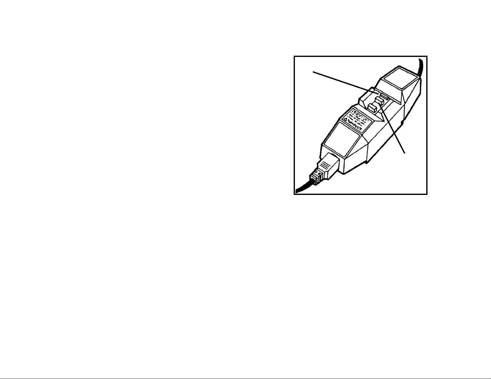
GROUND FAULT PROTECTION
4
The XES 8855 Engineering Printer is equipped with an
additional safety feature, a Ground Fault Interrupter (GFI). This
safety device will remove all power to the printer if an e lectrical
fault is detected.
In the event that power is interrupted to the printer, locate the
GFI safety device on the power cord:
Check that a red indicator appears in the window (A) of the
safety device shown opposite.
If no indicator is present, press and release the black RESET
button (B). The red indicator should appear in the window, and
power should be restored to the printer.
if the device interrupts power to the printer again, or if power is
not restored by performing the above procedure, call Xerox
Service to correct the problem.
A
B
Page 11
PRINTER OVERVIEW
j
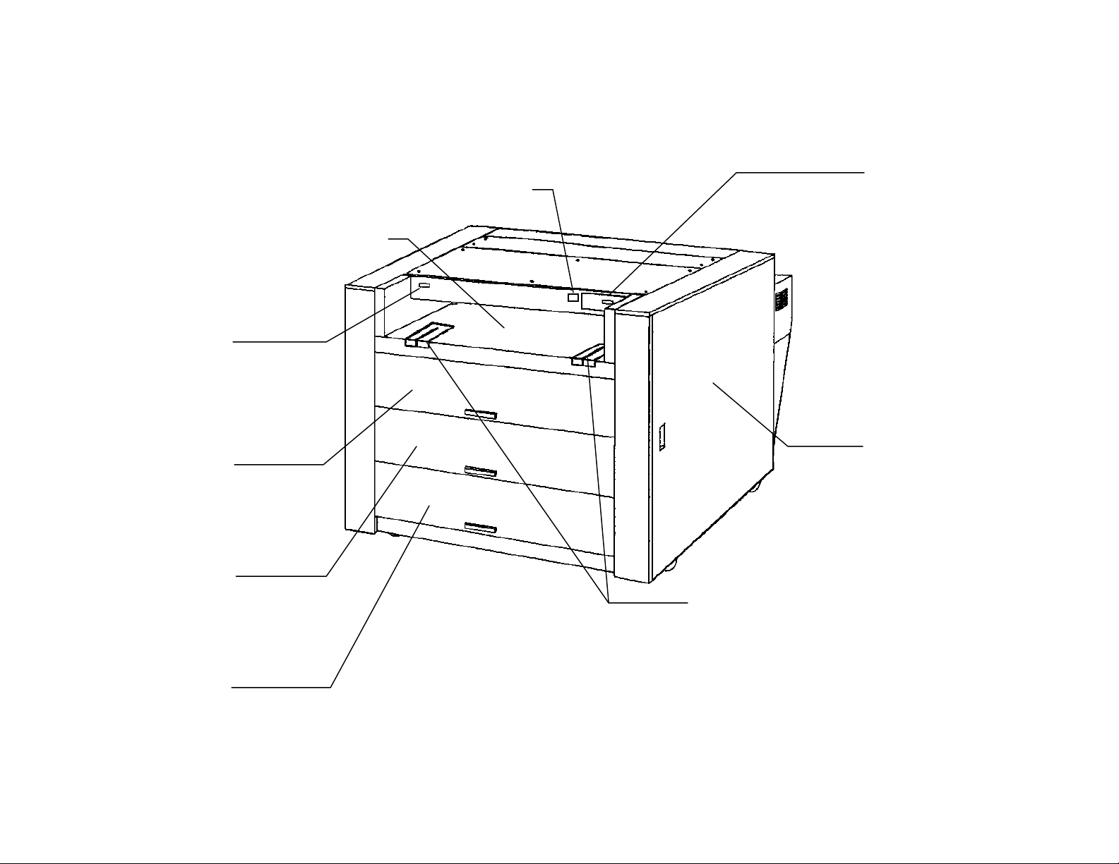
FRONT VIEW
Power On/Off
Switch
Press to switch
the printer on
and off.
Top Drawer
(Roll 1)
Open to load
paper rolls and
clear media
ams.
Middle Drawer
(Roll 2)
Open to load paper
rolls and clear
media jams.
Manual Bypass
Shelf
Insert cut sheets
here to bypass roll
media in drawers.
Billing Meter
Counts prints
for billing
purposes.
Status Display
Shows
selected media
and other
status
Right Side Door
Open to replace
toner cartridge
and toner waste
container, and to
clear media jams.
Bottom Drawer
(Rolls 3 & 4)
Open to load
paper rolls and
clear media jams.
Paper Guides
Adjust to size of
cut sheet media
in manual bypass
mode.
5
Printer Overview
Page 12
PRINTER OVERVIEW
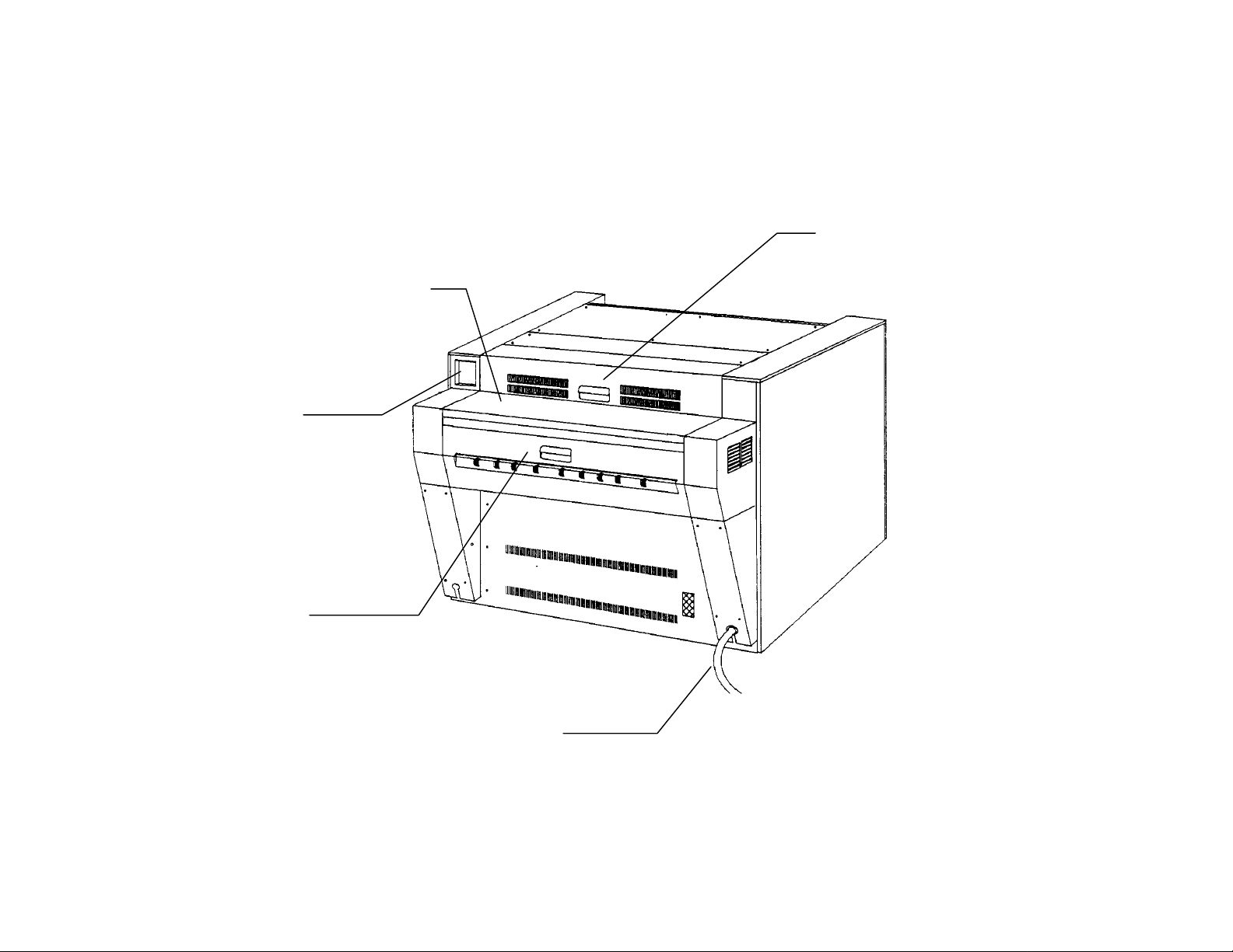
REAR VIEW
Interface
Connector
Connect
external input
device here.
Fuser Cover
Open to clear
media jams
and to replace
oil feeders.
6
Top Cover
Open to clear
media jams.
Exit Cover
Open to clear
media jams.
Power Cord
Connect to a
suitable power
outlet.
Page 13
PRINTER OVERVIEW
j
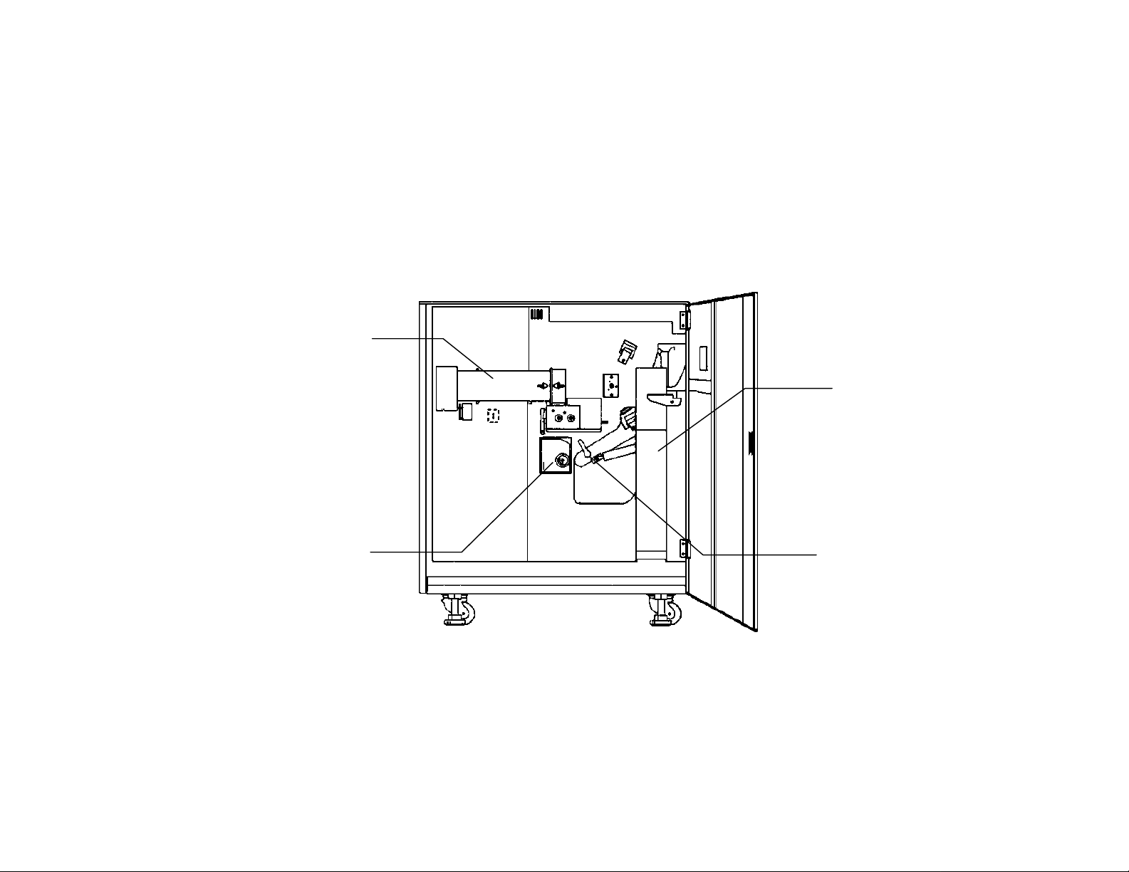
RIGHT SIDE VIEW
Toner Cartridge
Replace when
Status Display
indicates
cartridge is
empty.
Media Cutter
Turn to cut
media during
am clearance.
Toner Waste
Container
Replace at
stated
intervals.
Inner
Transport
Open to clear
media jams.
7
Page 14

8
Page 15

MEDIA INFORMATION
Loading the Media - Rolls 1, 2, 3
1. Pull the handle and open
the drawer which requires
the media.
2. Rewind the paper
remaining on the roll.
3. Hold the roll at both ends
and lift the roll out of the
drawer.
4. Press the green lever at
the end of the spindle.
5. Slide the spindle out of the
paper core.
6. Press the green locking
lever and insert the spindle
into the new roll of paper.
7. Align the edge of the roll
with the appropriate width
dimension on the spindle.
NOTE: To avoid unnecessary
strain, load the heaviest roll in
the Top Drawer and the
lightest rolls at the bottom.
8. Hold the roll at both ends
and set the roll into the
drawer.
9. Insert the lead edge of the
paper between the upper
and lower feed rollers.
10. Rotate the lower roller by
hand in order to feed an
inch of paper between the
rollers.
9
Media Information
Page 16

MEDIA INFORMATION
p
Loading the Media - Rolls 1, 2, 3
10
BELT
Roll 3 only:
11. Rotate the lower feed roller
until the lead edge is
visible in the center of the
viewing hole.
12. Set the switches for the
series and type of media
you have loaded, from
front to rear:
• Film
• Vellum
• Plain Paper
• Eng. (8.5”/11”) or Arch.
(9”/12")
NOTE: Ensure that the rubber
tracking belt is underneath the
lastic roller on the paper
spindle. If not, the printer will
indicate an out-of-paper
condition.
13. Push the drawer in until it
is closed and latched.
Page 17

MEDIA INFORMATION
Loading the Media - Roll 4
1. Pull the handle and open
the drawer which requires
the media.
2. Rewind the paper
remaining on the roll.
3. Hold the roll at both ends
and lift the roll out of the
drawer.
4. Press the green locking
lever at the end of the
spindle.
5. Slide the spindle out of the
paper core.
6. Press the green locking
lever and insert the spindle
into the new roll of paper.
7. Align the edge of the roll
with the appropriate width
dimension on the spindle.
NOTE: To avoid unnecessary
strain, load the heaviest roll in
the Top Drawer and the
lightest rolls at the bottom.
8. Hold the roll at both ends
and set the roll into the
drawer.
9. Insert the lead edge of the
paper between the upper
and lower feed rollers.
11
Page 18

MEDIA INFORMATION
p
Loading the Media - Roll 4
12
BELT
10. Rotate the green knob in
order to feed an inch of
paper between the feed
rollers.
11. Set the switches for the
series and type of media
you have loaded, from
front to rear:
• Film
• Vellum
• Plain Paper
• Eng. (8.5”/11”) or Arch.
(9”/12")
NOTE: Ensure that the rubber
tracking belt is underneath the
lastic roller on the paper
spindle. If not, the printer will
indicate an out-of-paper
condition.
12. Push the drawer in until it
is closed and latched.
Page 19

MEDIA INFORMATION
Making a Test Print
The printer is able to produce
a test print by itself, without
any external input device.
The length of the test print and
the roll selection can be
adjusted by Xerox Service.
1. Locate the test print switch
in the small opening next
to the Status Display.
2. Press the test print switch
with the point of a ball
point pen or something
similar.
• The printer will produce a
single test print.
13
Page 20

MEDIA INFORMATION
Dehumidifier
The printer is equipped with
heaters, which maintain the
media at a constant
temperature. The heaters
operate at night and in highhumidity conditions, in order to
avoid moisture-related
problems with the media.
Xerox Service can set the
heaters to operate in three
modes:
1. off when printing
2. off when printer is switched
on.
3. on all the time.
The heaters continue to
operate when the printer is
switched off, as long as the
printer is connected to a live
power outlet.
14
1. Open the Top Cover in
order to locate the
Dehumidifier Switch.
2. Set the switch to the
correct position for damp
or dry conditions:
• In damp conditions, the
dehumidifier switch should
be set to the H position.
• In dry conditions, the
dehumidifier switch should
be set to the L position.
Page 21

MANUAL BYPASS FEED
The bypass feed mode is used
when the print, which is being
sent to the printer, is a
different size than the roll
media loaded in the printer.
For example:
You want to send a C size
print, but there is no C size
media loaded in the printer.
You can use the bypass feed
mode to run the C size print,
using cut sheet media.
When the correct media is not
loaded for an incoming print,
the Status Display shows the
flashing code P-05.
1. Adjust the paper guides to
the correct size.
2. Feed the cut sheet media
squarely into the printer,
curl side down and
between the guides, until
the media stops.
• The Status Display
indicates the size when the
media is loaded (05-xx).
Manual Bypass
15
Page 22

16
Page 23

PROBLEM SOLVING
Status Indicators
Code
0
(blinking)
SLP-0 This indicator is displayed when the printer is in
SLP-1 This indicator is displayed when the printer is in
01-xx
02-xx
03-xx
04-xx
05-xx
0 is blinking on the Status Display Panel when the
printer is warming up or when the printer is making a
test print.
maximum power saver mode (no power to fuser).
reduced power saver mode (reduced power to fuser).
Indicates xx size media is loaded in Roll 1 (Top
Drawer).
Indicates xx size media is loaded in Roll 2 (Middle
Drawer).
Indicates xx size media is loaded in Roll 3 (Bottom
Drawer).
Indicates xx size media is loaded in Roll 4 (Bottom
Drawer).
Indicates xx size cut sheet media is loaded on Manual
Bypass Shelf.
Explanation
(continued)
17
Problem Solving
Page 24

PROBLEM SOLVING
Error Codes
18
Code Cause/What to Do
E-01 There is a problem with the printer. Press power off,
then on. If problem still exists, call for service.
E-02 There is a problem with the printer. Press power off,
then on. If problem still exists, call for service.
E-04 There is a problem with the printer. Press power off,
then on. If problem still exists, call for service.
E-05 There is a problem with the printer. Press power off,
then on. If problem still exists, call for service.
E-06 There is a problem with the printer. Press power off,
then on. If problem still exists, call for service.
E-07 There is a problem with the printer. Press power off,
then on. If problem still exists, call for service.
E-13 There is a problem with the printer. Press power off,
then on. If problem still exists, call for service.
Code
E-14 There is a problem with the printer. Press power off,
then on. If problem still e xists, call for service.
E-18 There is a problem with the printer. Press power off,
then on. If problem still e xists, call for service.
E-21 There is a problem with the printer. Press power off,
then on. If problem still e xists, call for service.
E-41 There is a problem with the printer. Press power off,
then on. If problem still e xists, call for service.
Cause/What to Do
(continued)
Page 25

PROBLEM SOLVING
Error Codes
Code Cause/What to Do
H-01 The Toner Waste Container is not installed correctly.
Go to Replacing the Toner Waste Container in this
manual.
J-01 There is a media jam in the printer.
Go to Clearing the Media Path in this manual.
J-02 There is a media jam in the printer.
Go to Clearing the Media Path in this manual.
J-03 There is a media jam in the printer.
Go to Clearing the Media Path in this manual.
J-04 There is a media jam in the printer.
Go to Clearing the Media Path in this manual.
J-05 There is a media jam in the printer.
Go to Clearing the Media Path in this manual.
J-11 There is a media jam in the printer.
Go to Clearing the Media Path in this manual.
J-12 There is a media jam in the printer.
Go to Clearing the Media Path in this manual.
J-13 There is a media jam in the printer.
Go to Clearing the Media Path in this manual.
J-14 There is a media jam in the printer.
Go to Clearing the Media Path in this manual.
Code
L-01 The printer senses a low toner condition.
Go to Replacing the Toner Cartridge in this manual.
P-01 Roll 1 is out of media or is loaded incorrectly in the
Top Drawer.
Go to Loading the Media in this manual.
P-02 Roll 2 is out of media or is loaded incorrectly in the
Middle Drawer.
Go to Loading the Media in this manual.
P-03 Roll 3 is out of media or is loaded incorrectly in the
Bottom Drawer.
Go to Loading the Media in this manual.
P-04 Roll 4 is out of media or is loaded incorrectly in the
Bottom Drawer.
Go to Loading the Media in this manual.
P-05 Media is not loaded or is incorrectly loaded at the
Manual Bypass Shelf.
Go to Manual Bypass Feed in this manual.
Cause/What to Do
(continued)
19
Page 26

PROBLEM SOLVING
Error Codes (continued)
Code Cause/What to Do
U-01 The Top Drawer is not closed. Open and close the
drawer firmly.
U-02 The Middle Drawer is not closed. Open and then close
the drawer firmly.
U-03 The Bottom Drawer is not closed. Open and then
close the drawer firmly.
U-04 The Inner Transport is not closed. Open and then
close the transport firmly.
20
Page 27

CLEARING THE MEDIA PATH
Media Jam J-01, J-02
When a jam J-01 occurs, the
media jams while feeding from
Roll 1 in the top drawer.
When a jam J-02 occurs, the
media jams while feeding from
Roll 2 in the middle drawer.
1. Pull the handle and open
the drawer indicated by the
jam code.
2. Manually rewind the roll
until the lead edge of the
paper comes out of the
feed rollers.
3. Trim the lead edge of the
roll squarely to remove any
torn or wrinkled paper.
4. Remove any scraps or torn
pieces of paper from the
inside of the printer.
5. Insert the lead edge of the
paper between the upper
and lower feed rollers.
6. Rotate the lower feed roller
by hand in order to feed an
inch of paper between the
feed rollers.
7. Push the drawer in until it
is closed and latched.
21
Clearing Media Path
Page 28

CLEARING THE MEDIA PATH
Media Jam J-03
When a jam J-03 occurs, the
media jams while feeding from
Roll 3 in the bottom drawer.
22
1. Pull the handle and open
the bottom drawer.
2. Manually rewind the roll
until the lead edge of the
paper comes out of the
feed rollers.
3. Trim the lead edge of the
roll squarely to remove any
torn or wrinkled paper.
4. Remove any scraps or torn
pieces of paper from the
inside of the printer.
5. Insert the lead edge of the
paper between the upper
and lower feed rollers.
6. Rotate the lower feed roller
by hand until the lead edge
is visible in the center of
the viewing hole.
7. Push the drawer in until it
is closed and latched.
Page 29

CLEARING THE MEDIA PATH
Media Jam J-04
When a jam J-04 occurs, the
media jams while feeding from
Roll 4 in the bottom drawer.
1. Pull the handle and open
the bottom drawer.
2. Manually rewind the roll
until the lead edge of the
paper comes out of the
feed rollers.
3. Trim the lead edge of the
roll squarely to remove any
torn or wrinkled paper.
4. Remove any scraps or torn
pieces of paper from the
inside of the printer.
5. Insert the lead edge of the
paper between the upper
and lower feed rollers.
6. Rotate the green knob in
the clockwise direction in
order to feed an inch of
paper between the feed
rollers.
7. Push the drawer into the
closed and latched
position.
23
Page 30

CLEARING THE MEDIA PATH
Media Jam J-05
When a jam J-05 occurs, the
printer detects media at the
Manual Bypass Shelf at power
on, or the media jams while
feeding from the Manual
Bypass Shelf.
1. Pull to open the top
drawer, middle drawer, and
Manual Bypass Shelf.
2. Remove any media from
the inside of the printer.
3. Push the drawers and
Manual Bypass Shelf into
the closed and latched
position.
4. Reload the media on the
Manual Bypass Shelf, curl
side down.
24
Page 31

CLEARING THE MEDIA PATH
Media Jam J-11
1. Open the Manual Bypass
Shelf and all three drawers
in order to locate the jam.
2. Rewind the jammed roll
until the lead edge of the
paper comes out of the
feed rollers.
4. If you are unable to rewind
the jammed roll easily,
gently loosen the jam
through the opening at the
rear of the Manual Bypass
Shelf.
5. Remove any scraps or torn
pieces of paper from the
inside of the printer.
6. Trim the lead edge of the
roll squarely to remove any
torn or wrinkled paper.
6. Insert the lead edge of the
paper between the upper
and lower feed rollers and
feed an inch of paper
between the feed rollers.
7. Roll 3 only: Rotate the
lower feed roller un til the
lead edge is visible in the
center of the viewing hole.
8. Push the drawers and
Manual Bypass Shelf into
the closed and latched
position.
25
Page 32

CLEARING THE MEDIA PATH
Media Jams J-12, J-13
26
1. Open the right side door.
2. Turn the green locking
lever to the left in order to
release the Inner
Transport.
3. Push down to lower the
Inner Transport and
remove any jammed
paper.
4. If paper has not been cut,
rotate the green cutter
knob one turn in the
clockwise direction in order
to cut the paper.
5. Turn the cutter knob until
the notch on the base of
the shaft is aligned with the
green marking at the nine
o’clock (270 degree)
position.
6. Turn the green locking
lever, lift and raise the
Inner Transport until it
latches securely in the
closed position.
7. Close the right side door.
Page 33

CLEARING THE MEDIA PATH
Media Jam J-14
1. Open the exit cover.
2. Gently pull the media out
of the printer in an even
motion.
3. Close the exit cover.
27
Page 34

28
Page 35

CARE
f
Replacing the Toner Cartridge
Toner cartridges are supplied
as part of a kit, which contains
eight toner cartridges, four
toner waste containers, and
three oil pads. The toner
cartridges are packed inside
the toner waste containers,
two to a container.
When the first of the two toner
cartridges in each container is
used, the toner waste
container should also be
replaced. (Refer to Replacing
the Toner Waste Container.)
Store the second toner
cartridge in a cool, dry place
until it is required.
1. Open the right side cover.
2. Rotate the toner cartridge
180 degrees in the upward
direction.
3. Pull down on the left end o
the toner supply
mechanism and remove
the cartridge.
(continued)
29
Care
Page 36

CARE
Replacing the Toner Cartridge (cont.)
30
4. Shake the new cartridge a
few times in order to
prepare the contents for
use.
5. Install the cartridge into the
toner supply mechanism
while keeping the sealed
opening on the upper side
of the cartridge.
6. Close the toner supply
mechanism.
7. Gently remove the seal by
pulling to the left.
8. Rotate the toner cartridge
180 degrees in the
downward direction.
9. Close the right side cover.
10. Dispose of the cartridge
properly. Seal the opening
of the cartridge with tape
or put the cartridge in a
plastic bag before
discarding.
Page 37

CARE
Replacing the Toner Waste Container
This printer does not have a
mechanism for detecting a full
toner waste container. The
printer is designed to operate
correctly if the toner waste
container is replaced after two
toner cartridges have been
used up.
The toner waste container
should be replaced at the
same time that the first of the
two toner cartridges, which are
packed in each container, is
installed.
Remove the second toner
cartridge from the container
and store it in a cool, dry place
until it is required.
1. Open the right side cover. 2. Move the retainer upward
and out of the way.
3. Gently move the top of the
waste container outward
and remove the container
from the printer. Take care
to avoid spilling any of the
contents.
4. Install a new waste
container in the printer.
Align the container
opening with the waste
toner tube in the printer.
5. Lower the retainer to
secure the waste
container.
6. Close the right side cover.
7. Dispose of the waste
container properly. Seal
the opening of the
container with tape or put
the container in a plastic
bag before discarding.
31
Page 38

CARE
Replacing the Oil Pads
Three oil pads, which apply
silicone oil to the surface of
the fuser roll, are located
under the fuser cover. The oil
pads are packed as part of the
toner and supplies kit, which
also contains eight toner
cartridges and four toner
waste containers.
The oil pads should be
replaced at the same time that
the first of the eight toner
cartridges is used in the
printer.
WARNING
Switch the printer off and
allow the fuser to cool for 15
minutes before replacing the
oil pads.
32
1. Open the fuser cover.
2. Replace the three oil pads
as shown.
Avoid contact with face or
eyes and wipe/wash your
hands thoroughly after
handling.
Page 39

CARE
Cleaning the Upper Corotron
Periodic cleaning of the
corotron will reduce print
quality problems caused by
accumulation of toner inside
the printer.
CAUTION
Use care when removing and
replacing the corotron to avoid
scratching the photosensitive
drum inside the printer. Do not
force the corotron in or out of
the printer.
1. Switch off the power to the
2. Open the right side cover.
3. Locate instruction label (1)
printer.
and follow the instructions
to remove and replace the
upper corotron: (1).
5. Lay the corotron on a flat
surface to expose the
corotron wires for
cleaning.
6. Clean the corotron wires
using a lint-free cloth
dampened with water.
7. Rub the wires gently from
end to end until most of
the toner is removed.
8. Turn the corotron over and
clean the wire(s) on the
other side.
9. Allow the corotron to dry
before replacing.
33
Page 40

CARE
Cleaning the Lower Corotron
Periodic cleaning of the
corotron will reduce print
quality problems caused by
accumulation of toner inside
the printer.
CAUTION
Use care when removing and
replacing the corotron to avoid
scratching the photosensitive
drum inside the printer. Do not
force the corotron in or out of
the printer.
1. Switch off the power to the
2. Open the right side cover.
3. Locate instruction label (2)
printer.
and follow the instructions
to remove and replace the
lower corotron: (2).
34
5. Lay the corotron on a flat
surface to expose the
corotron wires for
cleaning.
6. Clean the corotron wires
using a lint-free cloth
dampened with water.
7. Rub the wires gently from
end to end until most of
the toner is removed.
8. Allow the corotron to dry
before replacing.
Page 41

PRODUCT SPECIFICATIONS
XES 8855
36.75
in.
38 in.
50 in.
8855
138 in.
65.5 in.
53.5 in.
XES 8855 Dimensions
Width 53.5 in.
Depth 38.5 in.
Height 36.75 in.
Weight 880 lbs.
38.5
in.
49.5 in.
157 in.
Room Space Requirements
Height 96 in. (minimum)
Width 157 in.
Depth 138 in.
Room Air Change Requirement
(for Ozone Dissipation)
5 air changes per hour (minimum)
XEROX
XEROX
XEROXXEROX
SER# E1N XXXXXXX
Serial Number Location
All XES 8855 serial numbers start with an
E1N prefix, followed by several more digits.
Please have the serial number available
when calling for XES service.
35
Product Specifications
Page 42

PRODUCT SPECIFICATIONS
XES 8855
36
Electrical Specifications
Single Phase (Double pole circuit breaker, two
wires plus ground)
220 - 240 VAC
Nominal 60 Hz
20 Amp dedicated circuit
Warm-up Time: 2.5 minutes
Power Consumption
800 Watts (standby)
2500 Watts (running)
Heat Dissipation
35,000 BTU (running)
Environmental Requirements
Temperature: 50 to 85 degrees F.
Humidity: 15% to 85%
relative humidity
Maximum Elevation: 6560 Feet
Media Specifications
Type:
Bond (18 to 20 lb.)
Vellum (20 lb.)
Film (3 to 4 mil.)
Size:
Roll Feed:
11 in. to 36 in. width
(3 in. core diameter to 6.7 in. O.D.)
Manual Bypass Feed:
Minimum width: 11 in. (A LEF)
Maximum width: 36 in. (E SEF)
Print Size:
Minimum - 11 in. x 8.5 in. (A LEF)
Maximum - 36 in. x 48 in. (E SEF)
Maximum length - 20 feet
Page 43

FCC Compliance in the USA
EME Compliance in Canada
WARNING: This equipment has been tested and found to
comply with the limits for a Class A computing device pursuant to
Subpart J of Part 15 FCC Rules.
This equipment generates, uses, and can radiate radio
frequency energy, and if it is not installed and used in
accordance with the instruction manual, may cause interference
to radio communications. These limits are designed to provide
reasonable protection against such interference when operated
in a commercial environment. Operation of this equipment in a
residential area is likely to cause interference, in which case the
user, at his own expense, will be required to take whatever
measures may be required to correct the interference.
This digital apparatus does not exceed the Class A limits for
radio noise emissions from digital apparatus set out in the radio
interference regulations of the Canadian Department of
Communications.
Conformité EEM au Canada
Cet appareil numérique est conforme aux limites d'émission de
bruits radioélectriques pour les appareils de classe A stipulées
dans le Règlement sur le brouillage radioélectrique du Ministère
des Communications du Canada.
Page 44

Xerox Corporation
X
Multinational Customer and S ervice Education
780 Salt Road
Webster, New York 14580
ãããã
1996 by Xerox Corporation. All rights reserved.
â
XERO
, The Document Companyâ,the stylized
X and the identifying product names and
numbers herein are trademarks of XEROX
CORPORATION
Printed in the U.S.A
701P92414 12/00
 Loading...