

Page 1

Compact Inverter
CTi Automation - Phone: 800.894.0412 - Fax: 208.368.0415 - Web: www.ctiautomation.net - Email: info@ctiautomation.net
User's Manual
Page 2

Copyright © 2002-2007 Fuji Electric FA Components & Systems Co., Ltd.
CTi Automation - Phone: 800.894.0412 - Fax: 208.368.0415 - Web: www.ctiautomation.net - Email: info@ctiautomation.net
All rights reserved.
No part of this publication may be reproduced or copied without prior written permission from Fuji Electric FA
Components & Systems Co., Ltd.
All products and company names mentioned in this manual are trademarks or registered trademarks of their
respective holders.
The information contained herein is subject to change without prior notice for improvement.
Page 3

Preface
CTi Automation - Phone: 800.894.0412 - Fax: 208.368.0415 - Web: www.ctiautomation.net - Email: info@ctiautomation.net
This manual provides all the information on the FRENIC-Mini series of inverters including its operating
procedure, operation modes, and selection of peripheral equipment. Carefully read this manual for proper use.
Incorrect handling of the inverter may prevent the inverter and/or related equipment from operating correctly,
shorten their lives, or cause problems.
Listed below are the other materials related to the use of the FRENIC-Mini. Read them in conjunction with this
manual as necessary.
• FRENIC-Mini Instruction Manual
• RS-485 Communication User's Manual
• Catalog
• Application Guide
• RS-485 Communications Card Installation Manual
• Rail Mounting Base Installation Manual
• Mounting Adapter Installation Manual
• FRENIC Loader Instruction Manual
• Remote Keypad Instruction Manual
• Built-in Braking Resistor Installation Manual
The materials are subject to change without notice. Be sure to obtain the latest editions for use.
Documents related to Fuji inverters
Catalogs
FRENIC5000G11S/P11S
FRENIC-Eco
FRENIC5000VG7S
User's Manuals and Technical Information
FRENIC5000G11S/P11S Technical Information
FRENIC-Eco User's Manual
FRENIC5000VG7S Series User's Manual
i
Page 4

Safety precautions
CTi Automation - Phone: 800.894.0412 - Fax: 208.368.0415 - Web: www.ctiautomation.net - Email: info@ctiautomation.net
Read this manual thoroughly before proceeding with installation, connections (wiring), operation, or
maintenance and inspection. Ensure you have sound knowledge of the device and familiarize yourself with all
safety information and precautions before proceeding to operate the inverter.
Safety precautions are classified into the following two categories in this manual.
Failure to heed the information indicated by this symbol may lead to
dangerous conditions, possibly resulting in death or serious bodily injuries.
Failure to heed the information indicated by this symbol may lead to
dangerous conditions, possibly resulting in minor or light bodily injuries
and/or substantial property damage.
Failure to heed the information contained under the CAUTION title can also result in serious consequences.
These safety precautions are of utmost importance and must be observed at all times.
This product is not designed for use in appliances and machinery on which lives depend. Consult your Fuji
Electric representative before considering the FRENIC-Mini series of inverters for equipment and
machinery related to nuclear power control, aerospace uses, medical uses or transportation. When the
product is to be used with any machinery or equipment on which lives depend or with machinery or
equipment which could cause serious loss or damage should this product malfunction or fail, ensure that
appropriate safety devices and/or equipment are installed.
ii
Page 5

CTi Automation - Phone: 800.894.0412 - Fax: 208.368.0415 - Web: www.ctiautomation.net - Email: info@ctiautomation.net
Precautions for Use
Driving a 460V
general-purpose
motor
Torque
characteristics
and temperature
rise
In running
generalpurpose
motors
Vibration
Noise
When driving a 460V general-purpose motor with an inverter using
extremely long wires, damage to the insulation of the motor may occur. Use
an output circuit filter (OFL) if necessary after checking with the motor
manufacturer. Fuji motors do not require the use of output circuit filters
because of their good insulation.
When the inverter is used to run a general-purpose motor, the temperature
of the motor becomes higher than when it is operated using a commercial
power supply. In the low-speed range, the cooling effect will be weakened,
so decrease the output torque of the motor. If constant torque is required in
the low-speed range, use a Fuji inverter motor or a motor equipped with an
externally powered ventilating fan.
When an inverter-driven motor is mounted to a machine, resonance may be
caused by the natural frequencies of the machine system.
Note that operation of a 2-pole motor at 60 Hz or higher may cause
abnormal vibration.
* The use of a rubber coupling or vibration dampening rubber is
recommended.
* Use the inverter's jump frequency control feature to skip the resonance
frequency zone(s).
When an inverter is used with a general-purpose motor, the motor noise
level is higher than that with a commercial power supply. To reduce noise,
raise carrier frequency of the inverter. Operation at 60 Hz or higher can also
result in higher noise level.
In running
special
motors
High-speed
motors
Explosion-proof
motors
Submersible
motors and pumps
Brake motors
If the set frequency is set to 120 Hz or more to drive a high-speed motor,
test-run the combination of the inverter and motor beforehand to check for
safe operation.
When driving an explosion-proof motor with an inverter, use a combination
of a motor and an inverter that has been approved in advance.
These motors have a larger rated current than general-purpose motors.
Select an inverter whose rated output current is greater than that of the
motor.
These motors differ from general-purpose motors in thermal characteristics.
Set a low value in the thermal time constant of the motor when setting the
electronic thermal overload protection.
For motors equipped with parallel-connected brakes, their braking power
must be supplied from the primary circuit. If the brake power is connected
to the inverter's power output circuit by mistake, the brake will not work.
Do not use inverters for driving motors equipped with series-connected
brakes.
iii
Page 6

Geared motors
CTi Automation - Phone: 800.894.0412 - Fax: 208.368.0415 - Web: www.ctiautomation.net - Email: info@ctiautomation.net
If the power transmission mechanism uses an oil-lubricated gearbox or
speed changer/reducer, then continuous motor operation at low speed may
cause poor lubrication. Avoid such operation.
In running
special
motors
Environmental
conditions
Combination with
peripheral
devices
Synchronous
motors
Single-phase
motors
Installation
location
Installing an
MCCB or
RCD/GFCI
Installing an MC
in the secondary
circuit
Installing an MC
in the primary
circuit
It is necessary to take special measures suitable for this motor type. Contact
your Fuji Electric representative for details.
Single-phase motors are not suitable for inverter-driven variable speed
operation. Use three-phase motors.
* Even a single-phase inverter provides three-phase output, so use a
three-phase motor.
Use the inverter within the ambient temperature range from -10 to +50qC
(+14 to 122qF ).
The heat sink and braking resistor of the inverter may become hot under
certain operating conditions, so install the inverter on nonflammable
material such as metal.
Ensure that the installation location meets the environmental conditions
specified in Chapter 8, Section 8.5 "Operating Environment and Storage
Environment."
Install a recommended molded case circuit breaker (MCCB) or
residual-current-operated protective device (RCD)/ground-fault circuit
interrupter (GFCI) (with overcurrent protection) in the primary circuit of
the inverter to protect the wiring. Ensure that the circuit breaker capacity is
equivalent to or lower than the recommended capacity.
If a magnetic contactor (MC) is mounted in the inverter's secondary circuit
for switching the motor to commercial power or for any other purpose,
ensure that both the inverter and the motor are completely stopped before
you turn the MC on or off.
Do not connect a magnet contactor united with a surge killer to the inverter's
secondary circuit.
Do not turn the magnetic contactor (MC) in the primary circuit on or off
more than once an hour as an inverter failure may result.
If frequent starts or stops are required during motor operation, use
FWD/REV signals or the RUN/STOP key.
Protecting the
motor
The electronic thermal overload protection function of the inverter can
protect the motor. The operation level and the motor type (general-purpose
motor, inverter motor) should be set. For high-speed motors or
water-cooled motors, set a small value for the thermal time constant and
protect the motor.
If you connect the motor thermal relay to the motor with a long wire, a
high-frequency current may flow into the wiring stray capacitance. This
may cause the relay to trip at a current lower than the set value for the
thermal relay. If this happens, lower the carrier frequency or use the output
circuit filter (OFL).
iv
Page 7

Discontinuance of
CTi Automation - Phone: 800.894.0412 - Fax: 208.368.0415 - Web: www.ctiautomation.net - Email: info@ctiautomation.net
power-factor
correcting
capacitor
Do not mount power-factor correcting capacitors in the inverter’s primary
circuit. (Use the DC reactor to improve the inverter power factor.) Do not
use power-factor correcting capacitors in the inverter output circuit. An
overcurrent trip will occur, disabling motor operation.
Combination with
peripheral
devices
Wiring
Discontinuance of
surge killer
Reducing noise
Measures against
surge currents
Megger test
Control circuit
wiring length
Wiring length
between inverter
and motor
Wiring size
Wiring type
Do not connect a surge killer to the inverter's secondary circuit.
Use of a filter and shielded wires is typically recommended to satisfy EMC
directives.
If an overvoltage trip occurs while the inverter is stopped or operated under
a light load, it is assumed that the surge current is generated by open/close
of the phase-advancing capacitor in the power system.
* Connect a DC reactor to the inverter.
When checking the insulation resistance of the inverter, use a 500 V megger
and follow the instructions contained in the FRENIC-Mini Instruction
Manual, Chapter 7, Section 7.4 "Insulation Test."
When using remote control, limit the wiring length between the inverter and
operator box to 65.6 ft (20 m) or less and use twisted pair or shielded cable.
If long wiring is used between the inverter and the motor, the inverter will
overheat or trip as a result of overcurrent (high-frequency current flowing
into the stray capacitance) in the wires connected to the phases. Ensure that
the wiring is shorter than 164 ft (50 m). If this length must be exceeded,
lower the carrier frequency or mount an output circuit filter (OFL).
Select wires with a sufficient capacity by referring to the current value or
recommended wire size.
Do not use one multicore cable in order to connect several inverters with
motors.
Selecting
inverter
capacity
Transportation and
storage
Grounding Securely ground the inverter using the grounding terminal.
Select an inverter according to the applicable motor ratings listed in the
Driving
general-purpose
motor
Driving special
motors
When transporting or storing inverters, follow the procedures and select locations that meet the
environmental conditions listed in Chapter 1, Section 1.3 "Transportation" and Section 1.4
"Storage Environment."
standard specifications table for the inverter.
When high starting torque is required or quick acceleration or deceleration
is required, select an inverter with a capacity one size greater than the
standard.
Select an inverter that meets the following condition:
Inverter rated current > Motor rated current
v
Page 8

How this manual is organized
CTi Automation - Phone: 800.894.0412 - Fax: 208.368.0415 - Web: www.ctiautomation.net - Email: info@ctiautomation.net
This manual contains chapters 1 through 9, appendices and glossary.
Part 1 General Information
Chapter 1 INTRODUCTION TO FRENIC-Mini
This chapter describes the features and control system of the FRENIC-Mini series, and the recommended
configuration for the inverter and peripheral equipment.
Chapter 2 PARTS NAMES AND FUNCTIONS
This chapter contains external views of the FRENIC-Mini series and an overview of terminal blocks, including a
description of the LED display and keys on the keypad.
Chapter 3 OPERATION USING THE KEYPAD
This chapter describes inverter operation using the keypad. The inverter features three operation modes (Running,
Programming and Alarm modes) which enable you to run and stop the motor, monitor running status, set function
code data, display running information required for maintenance, and display alarm data.
Part 2 Driving the Motor
Chapter 4 BLOCK DIAGRAMS FOR CONTROL LOGIC
This chapter describes the main block diagrams for the control logic of the FRENIC-Mini series of inverters.
Chapter 5 RUNNING THROUGH RS-485 COMMUNICATION (OPTION)
This chapter describes an overview of inverter operation through the RS-485 communications facility. Refer to
the RS-485 Communication User's Manual for details.
Part 3 Peripheral Equipment and Options
Chapter 6 SELECTING PERIPHERAL EQUIPMENT
This chapter describes how to use a range of peripheral equipment and options, FRENIC-Mini's configuration
with them, and requirements and precautions for selecting wires and crimp terminals.
Part 4 Selecting Optimal Inverter Model
Chapter 7 SELECTING OPTIMAL MOTOR AND INVERTER CAPACITIES
This chapter provides you with information about the inverter output torque characteristics, selection procedure,
and equations for calculating capacities to help you select optimal motor and inverter models. It also helps you
select braking resistors.
vi
Page 9

Part 5 Specifications
r
CTi Automation - Phone: 800.894.0412 - Fax: 208.368.0415 - Web: www.ctiautomation.net - Email: info@ctiautomation.net
Chapter 8 SPECIFICATIONS
This chapter describes specifications of the output ratings, control system, and terminal functions for the
FRENIC-Mini series of inverters. It also provides descriptions of the operating and storage environment, external
dimensions, examples of basic connection diagrams, and details of the protective functions.
Chapter 9 FUNCTION CODES
This chapter contains overview lists of seven groups of function codes available for the FRENIC-Mini series of
inverters and details of each function code.
Appendices
App.A Advantageous Use of Inverters (Notes on electrical noise)
App.B Japanese Guideline for Suppressing Harmonics by Customers Receiving High Voltage or Special High
Voltage
App.C Effect on Insulation of General-purpose Motors Driven with 460 V Class Inverters
App.D Inverter Generating Loss
App.E Conversion from SI Units
App.F Allowable Current of Insulated Wires
App.G Replacement Information
Glossary
Icons
The following icons are used throughout this manual.
This icon indicates information which, if not heeded, can result in the inverter not operating to
full efficiency, as well as information concerning incorrect operations and settings which can
result in accidents.
This icon indicates information that can prove handy when performing certain settings o
operations.
This icon indicates a reference to more detailed information.
vii
Page 10

CONTENTS
CTi Automation - Phone: 800.894.0412 - Fax: 208.368.0415 - Web: www.ctiautomation.net - Email: info@ctiautomation.net
Part 1 General Information
Chapter 1 INTRODUCTION TO FRENIC-Mini
1.1 Features..................................................................................................................................................... 1-1
1.2 Control System .........................................................................................................................................1-8
1.3 Recommended Configuration................................................................................................................... 1-9
Chapter 2 PARTS NAMES AND FUNCTIONS
2.1 External View and Allocation of Terminal Blocks.................................................................................... 2-1
2.2 LED Monitor, Potentiometer and Keys on the Keypad ............................................................................ 2-2
Chapter 3 OPERATION USING THE KEYPAD
3.1 Overview of Operation Modes .................................................................................................................3-1
3.2 Running Mode .......................................................................................................................................... 3-3
3.2.1 Run/stop the motor.............................................................................................................................. 3-3
3.2.2 Set up the set frequency and others..................................................................................................... 3-3
3.2.3 Monitor the running status .................................................................................................................. 3-5
3.2.4 Jog (inch) the motor ............................................................................................................................ 3-7
3.3 Programming Mode .................................................................................................................................. 3-8
3.3.1 Setting the function codes--"Data Setting".......................................................................................... 3-9
3.3.2 Checking changed function codes--"Data Checking" ....................................................................... 3-13
3.3.3 Monitoring the running status--"Drive Monitoring" ......................................................................... 3-14
3.3.4 Checking I/O signal status--"I/O Checking" ..................................................................................... 3-17
3.3.5 Reading maintenance information--"Maintenance Information" ...................................................... 3-21
3.3.6 Reading alarm information--"Alarm Information"............................................................................ 3-22
3.4 Alarm Mode............................................................................................................................................ 3-26
3.4.1 Releasing the alarm and transferring the inverter to Running mode................................................. 3-26
3.4.2 Displaying the alarm history ............................................................................................................. 3-26
3.4.3 Displaying the running information when an alarm occurs ..............................................................3-27
3.4.4 Transferring to Programming mode.................................................................................................. 3-27
Part 2 Driving the Motor
Chapter 4 BLOCK DIAGRAMS FOR CONTROL LOGIC
4.1 Symbols Used in the Block Diagrams and their Meanings.......................................................................4-1
4.2 Drive Frequency Command Generator..................................................................................................... 4-2
4.3 Drive Command Generator....................................................................................................................... 4-4
4.4 Terminal Command Decoders .................................................................................................................. 4-6
4.5 Digital Output Selector ........................................................................................................................... 4-10
4.6 Analog Output (FMA) Selector .............................................................................................................. 4-12
4.7 Drive Command Controller .................................................................................................................... 4-14
4.8 PID Frequency Command Generator......................................................................................................4-16
viii
Page 11

Chapter 5 RUNNING THROUGH RS-485 COMMUNICATION (OPTION)
CTi Automation - Phone: 800.894.0412 - Fax: 208.368.0415 - Web: www.ctiautomation.net - Email: info@ctiautomation.net
5.1 Overview on RS-485 Communication...................................................................................................... 5-1
5.1.1 Common specifications....................................................................................................................... 5-2
5.1.2 Connector specifications ..................................................................................................................... 5-3
5.1.3 Connection .......................................................................................................................................... 5-3
Part 3 Peripheral Equipment and Options
Chapter 6 SELECTING PERIPHERAL EQUIPMENT
6.1 Configuring the FRENIC-Mini................................................................................................................. 6-1
6.2 Selecting Wires and Crimp Terminals....................................................................................................... 6-2
6.2.1 Recommended wires ........................................................................................................................... 6-4
6.2.2 Crimp terminals................................................................................................................................... 6-6
6.3 Peripheral Equipment ............................................................................................................................... 6-7
6.4 Selecting Options .................................................................................................................................... 6-13
6.4.1 Peripheral equipment options............................................................................................................ 6-13
6.4.2 Options for operation and communications ...................................................................................... 6-21
6.4.3 Extended installation kit options ....................................................................................................... 6-24
6.4.4 Meter options .................................................................................................................................... 6-27
Part 4 Selecting Optimal Inverter Model
Chapter 7 SELECTING OPTIMAL MOTOR AND INVERTER CAPACITIES
7.1 Selecting Motors and Inverters................................................................................................................. 7-1
7.1.1 Motor output torque characteristics..................................................................................................... 7-1
7.1.2 Selection procedure............................................................................................................................. 7-4
7.1.3 Equations for selections ...................................................................................................................... 7-7
7.1.3.1 Load torque during constant speed running ................................................................................7-7
7.1.3.2 Acceleration and deceleration time calculation........................................................................... 7-8
7.1.3.3 Heat energy calculation of braking resistor............................................................................... 7-11
7.1.3.4 Calculating the RMS rating of the motor .................................................................................. 7-12
7.2 Selecting a Braking Resistor................................................................................................................... 7-13
7.2.1 Selection procedure........................................................................................................................... 7-13
7.2.2 Notes on selection ............................................................................................................................. 7-13
ix
Page 12

Part 5 Specifications
CTi Automation - Phone: 800.894.0412 - Fax: 208.368.0415 - Web: www.ctiautomation.net - Email: info@ctiautomation.net
Chapter 8 SPECIFICATIONS
8.1 Standard Models ....................................................................................................................................... 8-1
8.1.1 Three-phase 230 V .............................................................................................................................. 8-1
8.1.2 Three-phase 460 V .............................................................................................................................. 8-2
8.1.3 Single-phase 230 V ............................................................................................................................. 8-3
8.2 Models Available on Order ....................................................................................................................... 8-4
8.2.1 EMC filter built-in type....................................................................................................................... 8-4
8.2.1.1 Three-phase 230 V ...................................................................................................................... 8-4
8.2.1.2 Three-phase 460 V ...................................................................................................................... 8-5
8.2.1.3 Single-phase 230 V ..................................................................................................................... 8-6
8.2.2 Braking resistor built-in type............................................................................................................... 8-7
8.2.2.1 Three-phase 230 V ...................................................................................................................... 8-7
8.2.2.2 Three-phase 460 V ...................................................................................................................... 8-8
8.3 Common Specifications ............................................................................................................................ 8-9
8.4 Terminal Specifications .......................................................................................................................... 8-11
8.4.1 Terminal functions ............................................................................................................................ 8-11
8.4.2 Terminal block arrangement.............................................................................................................. 8-23
8.4.3 Terminal arrangement diagram and screw specifications.................................................................. 8-24
8.4.3.1 Main circuit terminals ............................................................................................................... 8-24
8.4.3.2 Control circuit terminal ............................................................................................................. 8-25
8.5 Operating Environment and Storage Environment ................................................................................. 8-26
8.5.1 Operating environment...................................................................................................................... 8-26
8.5.2 Storage environment ......................................................................................................................... 8-27
8.5.2.1 Temporary storage ..................................................................................................................... 8-27
8.5.2.2 Long-term storage ..................................................................................................................... 8-27
8.6 External Dimensions............................................................................................................................... 8-28
8.6.1 Standard models and models available on order (braking resistor built-in type) .............................. 8-28
8.6.2 Models available on order (EMC filter built-in type)........................................................................8-30
8.7 Connection Diagrams ............................................................................................................................. 8-32
8.7.1 Keypad operation .............................................................................................................................. 8-32
8.7.2 Operation by external signal inputs................................................................................................... 8-33
8.8 Details of Protective Functions............................................................................................................... 8-34
Chapter 9 FUNCTION CODES
9.1 Function Code Tables ............................................................................................................................... 9-1
9.2 Details of Function Codes....................................................................................................................... 9-12
9.2.1 F codes (Fundamental functions)...................................................................................................... 9-12
9.2.2 E codes (Extension terminal functions)............................................................................................. 9-33
9.2.3 C codes (Control functions of frequency) ......................................................................................... 9-46
9.2.4 P codes (Motor parameters) ..............................................................................................................9-49
9.2.5 H codes (High performance functions)............................................................................................. 9-51
9.2.6 J codes (Application functions)......................................................................................................... 9-64
9.2.7 y codes (Link functions)....................................................................................................................9-70
x
Page 13

Appendices
CTi Automation - Phone: 800.894.0412 - Fax: 208.368.0415 - Web: www.ctiautomation.net - Email: info@ctiautomation.net
App.A Advantageous Use of Inverters (Notes on electrical noise)................................................................... A-1
A.1 Effect of inverters on other devices.................................................................................................... A-1
A.2 Noise .................................................................................................................................................. A-2
A.3 Noise prevention ................................................................................................................................ A-4
App.B Japanese Guideline for Suppressing Harmonics by Customers Receiving High Voltage or
Special High Voltage ........................................................................................................................... A-12
B.1 Application to general-purpose inverters ......................................................................................... A-12
B.2 Compliance to the harmonic suppression for customers receiving high voltage or
special high voltage.......................................................................................................................... A-13
App.C Effect on Insulation of General-purpose Motors Driven with 460 V Class Inverters.......................... A-17
C.1 Generating mechanism of surge voltages......................................................................................... A-17
C.2 Effect of surge voltages.................................................................................................................... A-18
C.3 Countermeasures against surge voltages .......................................................................................... A-18
C.4 Regarding existing equipment.......................................................................................................... A-19
App.D Inverter Generating Loss ..................................................................................................................... A-20
App.E Conversion from SI Units.................................................................................................................... A-21
App.F Allowable Current of Insulated Wires................................................................................................. A-23
App.G Replacement Information .................................................................................................................... A-25
G.1 External dimensions comparison tables ........................................................................................... A-25
G.2 Terminal arrangements and symbols................................................................................................ A-29
G.3 Function codes ................................................................................................................................. A-31
Glossary
xi
Page 14

Part 1 General Information
CTi Automation - Phone: 800.894.0412 - Fax: 208.368.0415 - Web: www.ctiautomation.net - Email: info@ctiautomation.net
Chapter 1 INTRODUCTION TO FRENIC-Mini
Chapter 2 PARTS NAMES AND FUNCTIONS
Chapter 3 OPERATION USING THE KEYPAD
Page 15

Chapter 1
CTi Automation - Phone: 800.894.0412 - Fax: 208.368.0415 - Web: www.ctiautomation.net - Email: info@ctiautomation.net
INTRODUCTION TO FRENIC-Mini
This chapter describes the features and control system of the FRENIC-Mini series, and the recommended
configuration for the inverter and peripheral equipment.
Contents
1.1 Features....................................................................................................................................................... 1-1
1.2 Control System............................................................................................................................................ 1-8
1.3 Recommended Configuration ..................................................................................................................... 1-9
Page 16

1.1 Features
CTi Automation - Phone: 800.894.0412 - Fax: 208.368.0415 - Web: www.ctiautomation.net - Email: info@ctiautomation.net
Optimum performance for traversing conveyors
• High starting torque, at 150% or more
Equipped with Fuji's original simplified torque-vector control system and the automatic torque boost
function, these inverters ensure consistent and powerful operation (when automatic torque boost and slip
compensation control are ON and start frequency is set at 5 Hz or more).
1.1 Features
Chap. 1 INTRODUCTION TO FRENIC-Mini
Figure 1.1 Torque Characteristics Data
(Automatic torque boost: ON)
Figure 1.2 Example of Output Torque Characteristics
• Braking resistor connectable to the inverter
FRENIC-Mini series of inverters features a built-in braking transistor (for inverters of 1/2 HP or larger),
which makes it possible for an optional braking resistor to be connected to increase the regenerative
braking ability for conveyance and transportation machinery that requires strong braking power. For
inverters of 2 HP or larger, it is also possible to select a model that incorporates a built-in braking resistor.
Refer to Chapter 8, Section 8.2.2 "Braking resistor built-in type" for details.
• Trip-free operation
The remarkably improved current limiting function (stall prevention) ensures trip-free operation even for
impact loads.
Figure 1.3 Example of Response for Impact Load Torque
• Stable operation even for a step load
The slip compensation function ensures stable operation even when the motor load fluctuates (step load).
Figure 1.4 Example of Response for Step Load Torque (Refer to the note in Figure 1.2 for the test configuration.)
1-1
Page 17

• Reduced motor instability at low speed
Fuji's unique control method improves voltage control performance and reduces motor instability at low
speed to about a half or under (at 1 Hz) compared with that of conventional inverters.
Refer to Chapter 4, Section 4.7 "Drive Command Controller" for details.
Figure 1.5 Example of Instability Characteristics
Default functions for fans and pumps
• Automatic energy-saving function provided as standard
To minimize the total loss (motor loss plus inverter loss), rather than just the motor loss as in the
predecessor models, FRENIC-Mini saves even more power when used with fans or pumps.
Refer to Chapter 4, Section 4.7 "Drive Command Controller" for details.
* Energy savings vary depending on the motor characteristics.
Figure 1.6 Example of Energy Savings
• PID control function
Permits motor operation while controlling temperature, pressure, or flow rate without using an external
device such as a temperature regulator.
Refer to Chapter 4, Section 4.8 "PID Frequency Command Generator" for details.
• Cooling fan ON/OFF control function
The inverter's cooling fan can be turned off while the fan or pump is stopped for noise reduction and
energy savings.
The ideal functions to serve a multiplicity of needs for small-capacity inverters
• Compatible with a wide range of frequency settings
You can select the optimum frequency setting method that matches your machine or equipment via the
keypad (
speed settings (0 to 7 steps) or via RS-485 communications. (Refer to Chapter 4, Section 4.2 "Drive
Frequency Command Generator" and Chapter 9, Section 9.2.1 "F codes" for details.)
/
keys or potentiometer), analog input (4 to 20 mA, 0 to 10 V, 0 to 5 V, 1 to 5 V), multistep
1-2
Page 18

• A transistor output is provided
This enables an overload early warning, lifetime forecast or other information signals to be output during
operation.
Refer to function code E20 in Chapter 9, Section 9.2.2 "E codes (Extension terminal functions)."
• High output frequency - up to 400 Hz
The inverter can be used with equipment such as centrifugal separators that require a high motor speed. In
this case, you need to check whether the machine operation in combination with the motor is compatible or
not.
• Two points can be set for a non-linear V/f pattern.
The addition of an extra point (total: 2 points) for the non-linear V/f pattern, which can be set as desired,
improves the FRENIC-Mini's drive capability, because the V/f pattern can be adjusted to match a wider
application area.
Refer to Chapter 4, Section 4.7 "Drive Command Controller" for details.
Compact size
• Side-by-side mounting
More than one FRENIC-Mini inverter can be mounted side-by-side without any gap inside your system
control panel, thereby reducing the amount of space required for installation. (Ambient temperature: 40°C
(104°F) or lower)
1.1 Features
Chap. 1 INTRODUCTION TO FRENIC-Mini
(Example: Inverters of 3-phase 230 V, 1 HP or less)
• External dimensions compatible with Fuji FVR-C11S series
1-3
Page 19

• RS-485 communications card (option) can be installed internally
CTi Automation - Phone: 800.894.0412 - Fax: 208.368.0415 - Web: www.ctiautomation.net - Email: info@ctiautomation.net
This card can be installed inside the inverter's body without changing the dimensions. RS-485
communication is available as option.
Refer to Chapter 5, "RUNNING THROUGH RS-485 COMMUNICATION (OPTION)."
RS-485 communications
card (option)
(Example: Inverters of 3-phase 230 V, 1 HP or less)
• Models with built-in braking resistor are available on order
Inverters of 2 HP or over are available in a braking resistor built-in type. Requiring no installation or
wiring of an external braking resistor reduces the total mounting space.
Refer to Chapter 8, Section 8.2.2 "Braking resistor built-in type."
(Example: Inverters of 3-phase 230V, 2 HP)
Simplified operation and wiring
• Frequency setting potentiometer is standard equipment
The frequency can be adjusted easily by hand.
1-4
Page 20
1.1 Features
CTi Automation - Phone: 800.894.0412 - Fax: 208.368.0415 - Web: www.ctiautomation.net - Email: info@ctiautomation.net
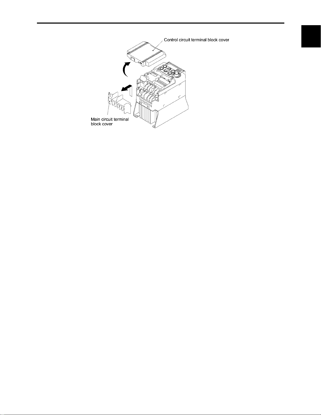
• Easy-to-remove/replace terminal block covers (for control circuit and main circuit)
• LED monitor on the keypad displaying all types of data
You can access and monitor all types of inverter's data and information including output frequency, set
frequency, load shaft speed, output current, output voltage, alarm history, input power etc. using built-in
keypad with LED.
Refer to Chapter 3, "OPERATION USING THE KEYPAD."
Chap. 1 INTRODUCTION TO FRENIC-Mini
• Menu mode accessible from the keypad
You can easily access the menu mode including "Data setting," "Data checking," "Drive monitoring," "I/O
checking," "Maintenance information," and "Alarm information."
Refer to Chapter 3, "OPERATION USING THE KEYPAD."
1-5
Page 21

Maintenance
CTi Automation - Phone: 800.894.0412 - Fax: 208.368.0415 - Web: www.ctiautomation.net - Email: info@ctiautomation.net
FRENIC-Mini series features the following facilities useful for maintenance.
Refer to Chapter 3, Section 3.3.5 "Reading Maintenance Information" and the FRENIC-Mini
Instruction Manual, Chapter 7 "MAINTENANCE AND INSPECTION" for details.
• The lifetime of the DC link bus capacitor (reservoir capacitor) can be estimated
The capacitor's condition compared with its initial state can be confirmed.
• Long-life cooling fan
Use of a long-life cooling fan (estimated service life: 7 years for operation at an ambient temperature of
40°C (104°F)) reduces maintenance cost.
• Recording and display of cumulative running time of the inverter
The inverter records and displays the accumulated running time of the inverter itself, the printed circuit
board and cooling fan.
• Alarm history for up to 4 latest alarms
The inverter records detailed information for up to 4 alarms that occurred most recently, which can also be
displayed on the LED.
Refer to Chapter 3, Section 3.3.6 "Reading alarm information."
• Lifetime forecast signal via transistor output
This signal is output when the reservoir capacitor in the DC link bus, the electrolytic capacitors on the
printed circuit board, or the cooling fans have been nearing the end of their service life.
Refer to function code E20 in Chapter 9, Section 9.2.2 "E codes (Extension terminal functions)" for
details.
Interface for peripheral devices and comprehensive protective functions
• All models are equipped with an inrush current suppression circuit.
FRENIC-Mini series features an inrush current suppression circuit as standard in all models to reduce the
cost of peripheral devices such as input magnetic contactor.
• Terminals for a DC reactor (DCR) provided as standard
Terminals for connection of a DCR, which are necessary for suppressing harmonics, are provided as
standard in all models.
• Input/output phase loss protective function
FRENIC-Mini series can detect output phase loss at all times during starting and running. This feature
assists you for keeping operation of your system stable.
• Switchable sink/source
The input/output mode (sink/source) of the digital input terminals can be switched by means of an internal
jumper switch. No engineering change is required in other control devices including PLC.
• Motor can be protected by a PTC thermistor
The motor is protected by PTC (Positive Temperature Coefficient) thermistor which detects the motor's
temperature and stops the inverter before the motor is overheated.
1-6
Page 22

Flexible through optionals
CTi Automation - Phone: 800.894.0412 - Fax: 208.368.0415 - Web: www.ctiautomation.net - Email: info@ctiautomation.net
• Function code copy function
The optional remote keypad includes a built-in copy facility, so you can copy function code data set in a
source inverter and duplicate it into a destination inverter.
• Inverter support loader software available
The inverter support loader program (Windows-based), which simplifies the setting of function codes, is
provided as an option.
Refer to Chapter 5, "RUNNING THROUGH RS-485 COMMUNICATION (OPTION)" for details.
• Mounting on DIN rail
Using the rail-mounting base (option), the inverter can easily be mounted on a DIN rail [1.38 inch (35 mm)
wide].
Refer to Chapter 6, "SELECTING PERIPHERAL EQUIPMENT" for details.
• Easy replacement of older models with new ones
Using the mounting adapter (option) makes it possible to mount the latest models without drilling any
additional holes.
Refer to Chapter 6, "SELECTING PERIPHERAL EQUIPMENT" for details.
• Remote operation
Using the optional RS-485 communications card and remote keypad together with remote operation
extension cable enables you to easily operate the inverter from a remote location, such as outside the
control panel where the inverter is installed.
Refer to Chapter 5, "RUNNING THROUGH RS-485 COMMUNICATION (OPTION)" and
Chapter 6, "SELECTING PERIPHERAL EQUIPMENT" for details.
1.1 Features
Chap. 1 INTRODUCTION TO FRENIC-Mini
Wide variations
The wide range of models available in the FRENIC-Mini series of inverters is certain to flexibly meet your
various system needs.
• The 460 V series is available in addition to the 230 V series (3-phase, single-phase).
• Models with built-in EMC filter and built-in braking resistors are also available.
•
An optional RS-485 communications card enables your system to feature network driven
management.
Refer to Chapter 8, "SPECIFICATIONS" for details.
Global products
FRENIC-Mini series of inverters are designed for use in global market in conformity with the global
standards listed below.
• All standard models conform to the EC Directive (CE Marking), UL standards (UL-Listed) and
Canadian standards (cUL-Listed).
All standard FRENIC-Mini inverters conform to European and North American/Canadian standards,
enabling standardization of the specifications for machines and equipment used at home and abroad.
• If a model with a built-in EMC filter is used, the model conforms to the European EMC Directive.
1-7
Page 23
1.2 Control System
This section gives you a general overview of inverter control systems and features specific to the
FRENIC-Mini series of inverters.
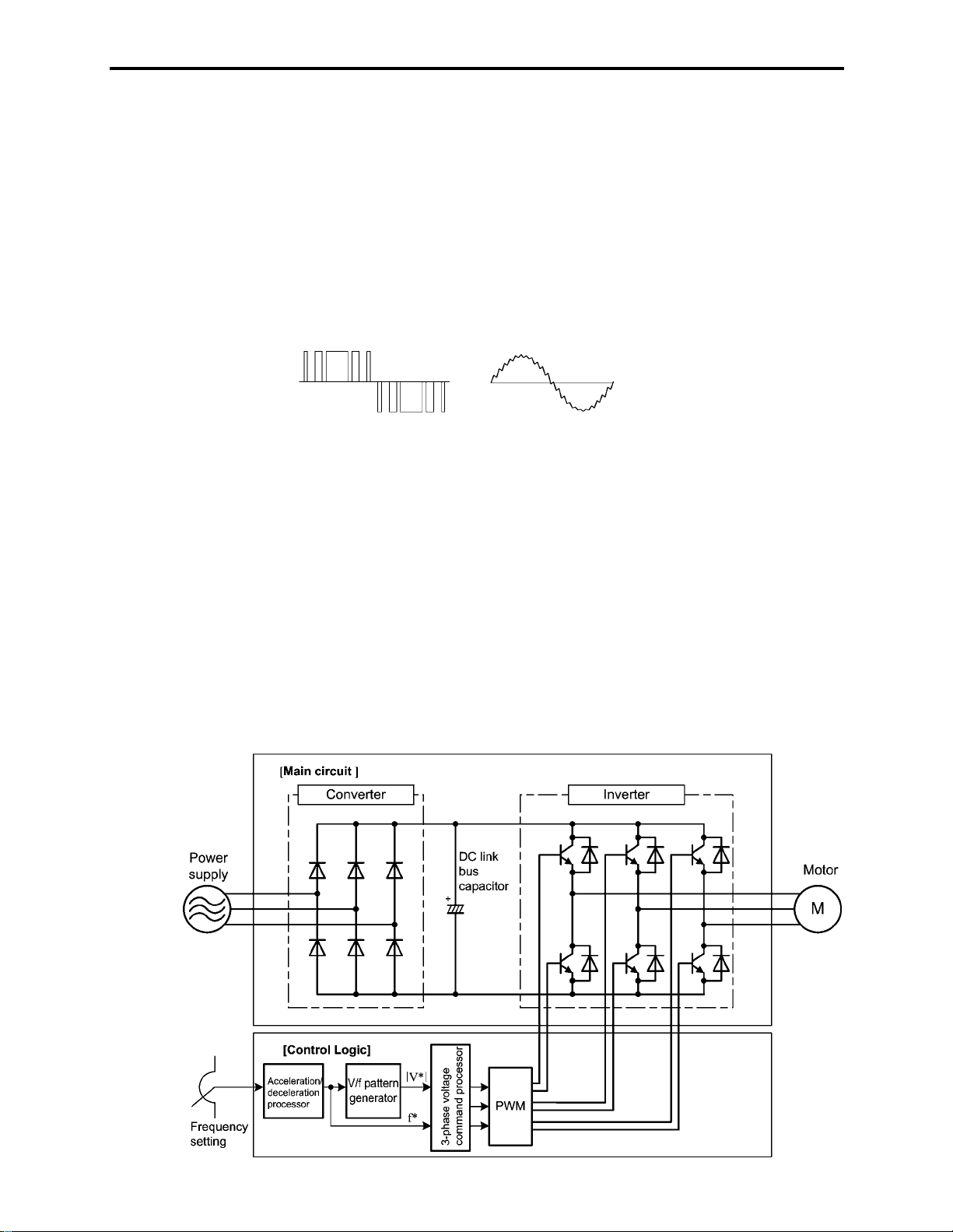
As shown in Figure 1.8, single- or three-phase commercial power is converted to DC power in the
converter section, which is then used to charge the capacitor on the DC link bus. According to control
commands or signals generated in the control logic, the inverter modulates the electricity charged in the
capacitor to PWM (Pulse Width Modulation) format and feeds the output to the motor. The modulation
frequency is called "carrier frequency." As shown in Figure 1.7, the voltage waveform of the modulated
power source produces pulse train with positive and negative polarity synchronized with the inverter's
output command frequency. The inverter feeds the produced output as drive power with sinusoidal current
waveform like that of ordinary commercial power lines.
PWM voltage waveform Current waveform
Figure 1.7 Output Voltage and Current Waveform of the Inverter
For the set frequency given in the control logic, the accelerator/decelerator processor calculates the
acceleration/deceleration rate required by run/stop control of the motor and transfers the calculated results
to the 3-phase voltage command processor directly or via the V/f pattern generator.
Refer to Chapter 4, Section 4.7 "Drive Command Controller" for details.
The FRENIC-Mini series features a simplified magnetic flux estimator which is added in the V/f pattern
processing section. This feature automatically controls the voltage level applied to the motor according to
the motor load so as to make the motor generate more stable and higher torque even during low speed
operation. This "Simplified Torque-Vector Control" is unique to Fuji inverters.
The control logic section, which is the very brain of the inverter, allows you to customize the inverter's
driving patterns using the function code settings.
Refer to Chapter 4 "BLOCK DIAGRAMS FOR CONTROL LOGIC" for details.
Figure 1.8 Simplified Control System Diagram of FRENIC-Mini
1-8
Page 24

1.3 Recommended Configuration
CTi Automation - Phone: 800.894.0412 - Fax: 208.368.0415 - Web: www.ctiautomation.net - Email: info@ctiautomation.net
1.3 Recommended Configuration
To control a motor with an inverter correctly, you should consider the rated capacity of both the motor and
the inverter and ensure that the combination matches the specifications of the machine or system to be
used. Refer to Chapter 7, "SELECTING OPTIMAL MOTOR AND INVERTER CAPACITIES" for
details.
After selecting the rated capacity, select appropriate peripheral equipment for the inverter, then connect
them to the inverter.
Refer to Chapter 6, "SELECTING PERIPHERAL EQUIPMENT" and Chapter 8, Section 8.7
"Connection Diagrams" for details on the selection and connection of peripheral equipment.
Figure 1.9 shows the recommended configuration for an inverter and peripheral equipment.
Chap. 1 INTRODUCTION TO FRENIC-Mini
Figure 1.9 Recommended Configuration Diagram
1-9
Page 25

Chapter 2
CTi Automation - Phone: 800.894.0412 - Fax: 208.368.0415 - Web: www.ctiautomation.net - Email: info@ctiautomation.net
PARTS NAMES AND FUNCTIONS
This chapter contains external views of the FRENIC-Mini series and an overview of terminal blocks, including
a description of the 7-segment LED monitor and keys on the keypad.
Contents
2.1 External View and Allocation of Terminal Blocks ...................................................................................... 2-1
2.2 LED Monitor, Potentiometer and Keys on the Keypad............................................................................... 2-2
Page 26

2.1 External View and Allocation of Terminal Blocks
r
CTi Automation - Phone: 800.894.0412 - Fax: 208.368.0415 - Web: www.ctiautomation.net - Email: info@ctiautomation.net
2.1 External View and Allocation of Terminal Blocks
Figures 2.1 and 2.2 show the external and bottom views of the FRENIC-Mini.
(1) External and bottom views
Keypad
Nameplate
Main circuit terminal
block cover
Cooling fan
Heat sink
Control circuit terminal
bock cover
Figure 2.1 External Views of FRENIC-Mini
Barrie
for the RS-485
communications port*
Control circuit wire port
DB, P1, P (+) and N (-) cable port
L1/R, L2/S, L3/T, U, V, W,
grounding wire port
L1/R, L2/S, L3/T, P1, P (+),
N(-) wire port
DB, U, V, W,
grounding wire
port
Control circuit terminal
block cover
Chap. 2 PARTS NAMES AND FUNCTIONS
(a) FRN001C1S-2U (b) FRN002C1S-2U
(*When connecting the RS-485 communications cable, remove the control circuit terminal block cover and snip off the barrier provided
in it using nippers.)
Figure 2.2 Bottom View of FRENIC-Mini
(2) Allocation of terminals
RS-485 communications card
connector
Control circuit terminal
block
Grounding terminal
Power input terminal block
Inverter output terminal block
SINK/SOURCE jumper switch
DC reactor, braking resistor and
DC link bus terminal block
Grounding terminal
(FRN002C1S-2U)
Figure 2.3 Enlarged View of the Terminal Blocks
The above figures show three-phase power source models. The terminal allocation of the power input
terminals L1/R, L2/S, L3/T, and grounding terminals for single-phase models differs from that shown in
above figures.
Refer to Chapter 8 "SPECIFICATIONS" for details on terminal functions, allocation and
connection and to Chapter 6, Section 6.2.1 "Recommended wires" when selecting wires.
For details on the keys and their functions, refer to Section 2.2 "LED Monitor, Potentiometer and
Keys on the Keypad." For details on keying operation and function code setting, refer to Chapter 3
"OPERATION USING THE KEYPAD."
2-1
Page 27

2.2 LED Monitor, Potentiometer and Keys on the Keypad
CTi Automation - Phone: 800.894.0412 - Fax: 208.368.0415 - Web: www.ctiautomation.net - Email: info@ctiautomation.net
As shown at the right, the keypad
consists of a 7-segment LED monitor,
a potentiometer (POT), and six keys.
The keypad allows you to run and stop
the motor, monitor running status, and
switch to the menu mode. In the menu
mode, you can set the function code
data to match your operating
requirements and monitor I/O signal
states, maintenance information, and
alarm information.
Table 2.1 Overview of Keypad Functions
Monitor, Potentiometer
and Keys
Four-digit, 7-segment LED monitor which displays the running status, data
settings, and alarm status of the inverter according to the operation modes*.
In Running mode, the monitor displays running status information (e.g.,
output frequency, current, and voltage). In Programming mode, it displays
menus, function codes and their data. In Alarm mode, it displays an alarm
code which identifies the error factor if the protective function is activated.
Program/Reset key
7-segment
LED monitor
Down key Up key Function/Data key
Figure 2.4 Keypad
Functions
PotentiometerRUN key
STOP key
Potentiometer (POT) which is used to manually set frequency, auxiliary
frequencies 1 and 2 or PID process command.
RUN key. Press this key to run the motor.
STOP key. Press this key to stop the motor.
/
UP/DOWN keys. Press these keys to select the setting items and change the
function data displayed on the LED monitor.
Program/Reset key. Press this key to switch the operation modes* of the
inverter.
Pressing this key in Running mode switches the inverter to Programming
mode and vice versa.
In Alarm mode, pressing this key after removing the error factor will switch
the inverter to Running mode.
Function/Data key.
Pressing this key in Running mode switches the information displayed
(output frequency (Hz), current (Amps) or voltage (V)).
Pressing this key in Programming mode displays the function code and sets
the data entered using
keys or the POT.
/
Pressing this key in Alarm mode displays information concerning the alarm
code currently displayed on the LED monitor.
*
FRENIC-Mini features three operation modes--Running, Programming, and Alarm modes. Refer to
Chapter 3, Section 3.1 "Overview of Operation Modes."
2-2
Page 28

■ LED monitor
CTi Automation - Phone: 800.894.0412 - Fax: 208.368.0415 - Web: www.ctiautomation.net - Email: info@ctiautomation.net
2.2 LED Monitor, Potentiometer and Keys on the Keypad
In Running mode, the LED monitor displays running status information (output frequency, current or
voltage); in Programming mode, it displays menus, function codes and their data; in Alarm mode, it
displays an alarm code which identifies the error factor if the protective function is activated.
If one of LED4 through LED1 is blinking, it means that the cursor is at this digit, allowing you to change
it.
If the decimal point of LED1 is blinking, it means that the currently displayed data is a PID process
command, not the frequency data usually displayed.
Table 2.2 Alphanumeric Characters on the LED Monitor
Character 7-segment Character 7-segment Character 7-segment Character 7-segment
0
1
2
3
LED4 LED3 LED2 LED1
Figure 2.5 7-Segment LED Monitor
9
A
b
C
#C
D
%E
i
J
K
L
+
L
M
.N
r
S
T
u
T
U
6
7
Chap. 2 PARTS NAMES AND FUNCTIONS
4
5
6
7
8
Special characters and symbols (numbers with decimal point, minus and underline)
0. - 9. - - _ _
■ Repeat function of / keys
d
E
F
G
H
F
'G
(H
)I
*J
M
O
n
o
P
q
P
Q
2R
S
V
W
X
y
Z
W
Y
Z
[
<
/ keys have a repeat function which helps you change displayed data speedily as follows:
Usually you press
If you hold down
/ keys once to increase or decrease the displayed value by 1, respectively.
either key so as to activate the repeat function, the displayed value will keep changing
in steps of 1 speedily. Note that when changing some function code data during running of the inverter
(not always possible), the displayed data will keep changing more slowly. This is to ensure safe and
stable operation.
2-3
Page 29
■ Continuous holding-down function for Program/Reset key
CTi Automation - Phone: 800.894.0412 - Fax: 208.368.0415 - Web: www.ctiautomation.net - Email: info@ctiautomation.net
Holding down the key longer (approx. one second or longer) moves the cursor on the LED monitor.
In Running mode, the cursor moves along digits; in Programming mode, it moves not only along digits
but to the next function code.
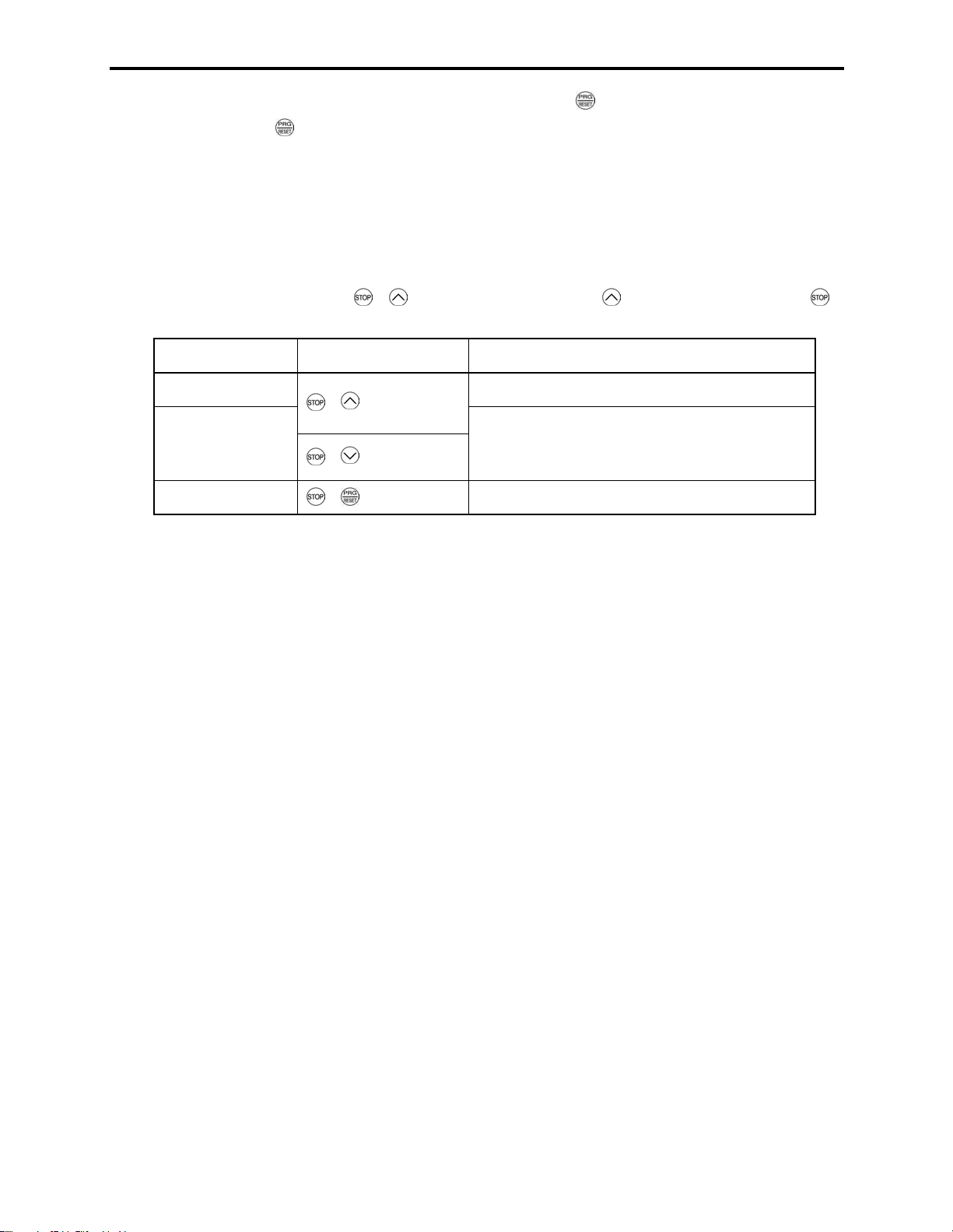
■ Simultaneous keying
Simultaneous keying means depressing two keys at the same time (expressed by "+"). FRENIC-Mini
supports simultaneous keying as listed below.
(For example, the expression "
+ keys" stands for pressing the key while holding down the
key.)
Operation modes Simultaneous keying Used to:
Running mode Control entry to/exit from jogging operation.
Programming mode
Alarm mode + keys Switch to Programming mode.
+ keys
+ keys
Change special function code data.
(Refer to codes F00 and H03 in Chapter 9
"FUNCTION CODES.")
2-4
Page 30

Chapter 3
CTi Automation - Phone: 800.894.0412 - Fax: 208.368.0415 - Web: www.ctiautomation.net - Email: info@ctiautomation.net
OPERATION USING THE KEYPAD
This chapter describes inverter operation using the keypad. The inverter features three operation modes
(Running, Programming and Alarm modes) which enable you to run and stop the motor, monitor running status,
set function code data, display running information required for maintenance, and display alarm data.
Contents
3.1 Overview of Operation Modes.................................................................................................................... 3-1
3.2 Running Mode ............................................................................................................................................ 3-3
3.2.1 Run/stop the motor.............................................................................................................................. 3-3
3.2.2 Set up the set frequency and others..................................................................................................... 3-3
3.2.3 Monitor the running status .................................................................................................................. 3-5
3.2.4 Jog (inch) the motor ............................................................................................................................ 3-7
3.3 Programming Mode .................................................................................................................................... 3-8
3.3.1 Setting the function codes--"Data Setting".......................................................................................... 3-9
3.3.2 Checking changed function codes--"Data Checking" ....................................................................... 3-13
3.3.3 Monitoring the running status--"Drive Monitoring" ......................................................................... 3-14
3.3.4 Checking I/O signal status--"I/O Checking" ..................................................................................... 3-17
3.3.5 Reading maintenance information--"Maintenance Information"
3.3.6 Reading alarm information--"Alarm Information"............................................................................ 3-22
3.4 Alarm Mode .............................................................................................................................................. 3-26
3.4.1 Releasing the alarm and transferring the inverter to Running mode................................................. 3-26
3.4.2 Displaying the alarm history ............................................................................................................. 3-26
3.4.3 Displaying the running information when an alarm occurs ..............................................................3-27
3.4.4 Transferring to Programming mode.................................................................................................. 3-27
........................................................... 3-21
Page 31

3.1 Overview of Operation Modes
CTi Automation - Phone: 800.894.0412 - Fax: 208.368.0415 - Web: www.ctiautomation.net - Email: info@ctiautomation.net
3.1 Overview of Operation Modes
FRENIC-Mini features the following three operation modes:
■ Running mode : This mode allows you to enter run/stop commands in regular operation. You
may also monitor the running status in realtime.
■ Programming mode : This mode allows you to set function code data and check a variety of
information relating to the inverter status and maintenance.
■ Alarm mode : If an alarm occurs, the inverter automatically enters this Alarm mode in which
the corresponding alarm code* and its related information may be displayed on
the LED monitor.
* Alarm code: Shows the error factor that has activated the protective function. For details,
refer to Chapter 8, Section 8.8 "Details of Protective Functions."
Figure 3.1 shows the status transition of the inverter between these three operation modes. If the inverter
is turned ON, it automatically enters Running mode, making it possible to start or stop the motor.
To make the transition between those operation modes, you need to press the specified keys as shown
below, except at the occurrence of an alarm. If an alarm occurs in Running mode, the inverter will
automatically switch to Alarm mode.
Chap. 3 OPERATION USING THE KEYPAD
Figure 3.1 Status Transition between Operation Modes
3-1
Page 32

The figure below shows the transition between the running status monitoring screens in Running mode,
that between the menu screens in Programming mode, and that between the alarm code screens in Alarm
mode.
*1 The speed monitor may display the output frequency (Hz), set frequency (Hz), load shaft speed (r/min), line speed
[ft/min. (m/min.)], and constant feeding rate time (min.) which can be selected by setting up function code E48.
*2 These PID-related information will appear only when the inverter is under the PID control. (Refer to Section
3.2.2.)
*3 This will appear only when timer operation is enabled by setting up function code C21. (Refer to Chapter 9,
Section 9.2.3 "C codes (Control functions of frequency).")
*4 This will appear only when the remote keypad (option) is set up for use.
Figure 3.2 Basic Screen Transition in Each Operation Mode
3-2
Page 33

3.2 Running Mode
CTi Automation - Phone: 800.894.0412 - Fax: 208.368.0415 - Web: www.ctiautomation.net - Email: info@ctiautomation.net
3.2 Running Mode
If the inverter is turned ON, it automatically enters Running mode in which you may:
(1) Run/stop the motor
(2) Set up the set frequency and others
(3) Monitor the running status (e.g., output frequency, output current)
(4) Jog (inch) the motor
3.2.1 Run/stop the motor
By factory default, pressing the key starts running the motor in the forward direction and pressing the
key brings the motor to a decelerated stop. The key is enabled only in Running mode.
Changing function code F02 data makes it possible to run the motor in the reverse direction by pressing
the
key, determine the motor rotational direction by entering input signals to the terminals, and
control the motor by pressing
3.2.2 Set up the set frequency and others
/
keys.
Chap. 3 OPERATION USING THE KEYPAD
By using the potentiometer and
and PID process commands. It is also possible to set up the set frequency as frequency, load shaft speed,
line speed, and constant feeding rate time by setting function code E48.
Setting up the set frequency with the potentiometer on the keypad (factory default)
If you set function code F01 to "4: Potentiometer on the keypad" (factory default) and select frequency
setting-1 with function codes E01 through E03 (Hz2/Hz1 = OFF), then the potentiometer becomes
enabled to set up the set frequency. Setting function code C30 to "4: Potentiometer on the keypad" and
selecting frequency setting-2 (Hz2/Hz1 = ON) also produce the same effect.
Setting up the set frequency with
If you set function code F01 to "0: Keypad operation" and select frequency setting-1, then
become enabled to set up the set frequency in Running mode. In any other operation modes, those keys
remain disabled.
Pressing
again makes it possible to change the set frequency. The new setting will be saved internally. Even if the
inverter is switched to any other frequency entry method and then returned to the keypad entry method,
the setting will be retained.
Further, even turning OFF the inverter will automatically save the setting into the non-volatile memory.
At the next time when the inverter is turned ON, the setting will become the default frequency.
If you set function code F01 to "0: Keypad operation" but do not select frequency setting-1, then
keys cannot be used for setting up the set frequency. Pressing those keys will just display the currently
selected set frequency.
/
keys calls up the set frequency with the lowest digit blinking. Pressing
/ keys on the keypad, you may set up the desired set frequency
/ keys
/
keys
/
keys
/
To set up the set frequency from any other displayed items, it is dependent on function code E48 data (=
4, 5, or 6) "LED monitor details (Select speed monitor)" as listed in the following table.
3-3
Page 34

E48 data "LED monitor details
■
(Select speed monitor)"
0: Output frequency (before slip
compensation)
1: Output frequency (after slip
compensation)
2: Set frequency Frequency setting
4: Load shaft speed Load shaft speed setting Frequency setting x E50
5: Line speed Line speed setting Frequency setting x E50
6: Constant feeding rate time
Set frequency display Conversion of displayed value
Frequency setting
Frequency setting
Constant feeding rate
time
E50
E39settingFrequency
u
If you set function code C30 to "0: Keypad operation" and select frequency setting-2, then
/
keys become also enabled to set up the set frequency.
Make setting under PID control
To enable PID control, you need to set function code J01 to 1 or 2.
In the PID control mode, the items that can be set or checked with
/
keys are different from those
under normal frequency control, depending upon the current LED monitor setting. If the LED monitor is
set to the speed monitor (E43 = 0), you may access manual feed commands (Set frequency) with
/
keys; if it is set to any other, you may access PID process commands with those keys.
Refer to Chapter 4, Section 4.8 "PID Frequency Command Generator" for details on the PID
control.
Setting the PID process command with the built-in potentiometer
Set function code E60 to "3: PID process command 1" and J02 to "1: PID process command 1." After
that, selecting PID control remote process command enables you to set the PID process command using
the built-in potentiometer.
Setting the PID process command with
/ keys
Set function code J02 to "0: Keypad operation" and set the LED monitor to the setting other than the
speed monitor (E43 = 0) in Running mode. This makes it possible to set the PID process command using
/ keys. This setting is possible only in Running mode.
Pressing
monitor. Pressing
keys displays the PID process command with the lowest digit blinking on the LED
/
/ keys again makes it possible to change the PID process command. Once the
PID process command is modified, it will be saved internally. Even if the inverter is switched to any
other PID process command entry method and then returned to the keypad entry method, the setting will
be retained.
Further, even turning OFF the inverter will automatically save the setting into the non-volatile memory.
At the next time when the inverter is turned ON, the setting will become the default PID process
command.
Even if the PID process command is selected ((SS4) = ON) in the multistep frequency, it is still possible
to set the process command using the keypad.
When function code J02 has been set to any value except 0, pressing
/ keys displays the PID
process command currently selected (setting is not possible).
When the PID process command is displayed, the decimal point next to the lowest digit on the LED
display blinks to discriminate it from the frequency setting.
3-4
Page 35

3.2 Running Mode
r
Setting up the set frequency with / keys under the PID control
To set the set frequency with / keys under the PID control, you need to specify the following
conditions:
- Set function code F01 to "0: Keypad operation."
- Select frequency setting-1 (Frequency settings from communications link: Disabled, and Multistep
frequency settings: Disabled) as manual speed command.
- Set the LED monitor to the speed monitor in Running mode.
The above setting is impossible in any operation mode except Running mode.
The setting procedure is the same as that for usual frequency setting.
If you press
/ keys in any conditions other than those described above, the following will appear:
Chap. 3 OPERATION USING THE KEYPAD
Frequency setting
Frequency
setting 1 (F01)
0 Disabled Disabled
from
communications
link
Other than the above
• When setting the frequency and others with
Multistep
frequency
setting
PID control
cancelled
PID enabled
Cancelled
PID enabled
Cancelled
/
Displayed using
Frequency setting by keypad
PID output (as final frequency
command)
Manual speed command
currently selected (frequency
setting)
/ keys
keys, the lowest digit on the display
will blink. Change the setting, starting from the lowest digit and the cursor will move
gradually to the next digit to be changed.
• When the data is to be changed rapidly, hold down the
key for 1 second or longer, and
the blinking cursor will move to the next digit where the data can be changed (curso
movement).
3.2.3 Monitor the running status
In Running mode, the seven items listed below can be monitored. Immediately after the inverter is
turned ON, the monitor item specified by function code E43 is displayed. Press the key to switch
between monitor items.
Table 3.1 Monitor Items
Monitor Items
Speed monitor
[Hz, r/min, ft/min (m/min), min]
Output current (A)
Input power (HP)
Output voltage (V)
PID process command (Note)
PID feedback value (Note)
Timer (sec) (Note)
Note: The PID process command and PID feedback value are displayed only under the PID control using a process
command (J01 = 1 or 2). Further, the timer (for timer operation) is only displayed when timer is enabled (C21 = 1).
Display Sample on
the LED monitor
C
R
W
3-5
Meaning of Displayed Value
Refer to Table 3.2.
Detected value
P: An alternative expression for kW
Commanded value
(PID process command or PID feedback value) u
(PID display coefficient A – B) + B
PID display coefficient A and B: Refer to
function codes E40 and E41
Remaining effective timer count
Page 36

Figure 3.3 shows the procedure example for selecting the desired monitor item.
CTi Automation - Phone: 800.894.0412 - Fax: 208.368.0415 - Web: www.ctiautomation.net - Email: info@ctiautomation.net
*1 The speed monitor may display the output frequency (Hz), set frequency (Hz), load shaft speed (r/min), line speed
[ft/min. (m/min.)], and contrast feeding rate time (min.) which can be selected by setting up function code E48.
*2 These PID-related information will appear only when the inverter is under the PID control. (Refer to Section
3.2.2.)
*3 This will appear only when timer operation is enabled by setting up function code C21. (Refer to Chapter 9,
Section 9.2.3 "C codes (Control functions of frequency).")
Figure 3.3 Monitor Item Selection Example
Table 3.2 lists the display items for the speed monitor that can be chosen with function code E48.
Table 3.2 Display Items on the Speed Monitor
Speed monitor items Function code E48 data Meaning of Displayed Value
Output frequency (before slip
compensation) (Hz)
(Factory default)
Output frequency (after slip
compensation) (Hz)
Set frequency (Hz) 2 Final set frequency
Load shaft speed (r/min) 4 Display value = Output frequency (Hz) x E50
Line speed [ft/min (m/min)] 5 Display value = Output frequency (Hz) x E50
Constant feeding rate time
(min)
*
Output frequencies contained in these formulas are output frequencies before slip compensation.
0 Pre-slip compensation frequency
1 Frequency actually being outputted
6
Display value =
E50
*
E39frequencyOutput
u
*
*
3-6
Page 37

3.2 Running Mode
CTi Automation - Phone: 800.894.0412 - Fax: 208.368.0415 - Web: www.ctiautomation.net - Email: info@ctiautomation.net
3.2.4 Jog (inch) the motor
In Running mode, pressing + keys at the same time (simultaneous keying) can make the inverter
ready for jogging. The
JoG
appears on the LED monitor.
To return the inverter from the ready-to-jog state to the usual running state, you need to press
keys simultaneously.
Using the external input signal command (JOG) also allows the transition between the ready-to-jog state
and usual running state.
Refer to function codes E01 to E03 in Chapter 9, Section 9.2.2 "E codes (Extension terminal
functions)" for details.
During jogging, the jogging frequency (C20) and acceleration/deceleration time for jogging (H54) will
apply. They are exclusively prepared for jogging and required to be set up individually.
When jogging the motor from the keypad, the inverter will only run while the
contrarily the moment the key is released, the inverter will decelerate and stop the motor.
The transition ( + keys) between the ready-to-jog state and usual running state is
enabled only when the inverter is not in operation.
key is held down, and
+
Chap. 3 OPERATION USING THE KEYPAD
3-7
Page 38

3.3 Programming Mode
CTi Automation - Phone: 800.894.0412 - Fax: 208.368.0415 - Web: www.ctiautomation.net - Email: info@ctiautomation.net
Pressing the key in Running mode switches the inverter to Programming mode. This mode provides
the following functions which can be easily selected with the menu-driven system.
(1) Data setting (Menu #1)
(2) Data checking (Menu #2)
(3) Drive monitoring (Menu #3)
(4) I/O checking (Menu #4)
(5) Maintenance information (Menu #5)
(6) Alarm information (Menu #6)
(7) Data copying (Menu #7)
The table below lists the menus, letters that will appear on the LED monitor, and functions. The leftmost
digit (numerals) of each letter string indicates the corresponding menu number and the remaining three
digits indicate the menu contents.
When the inverter enters Programming mode from the second time on, the menu that was selected last in
Programming mode will be displayed.
Table 3.3 Menus Available in Programming Mode
Menu
Menu #1
"Data setting"
Menu #2
"Data checking"
Menu #3
"Drive
monitoring"
Menu #4
"I/O checking"
LED monitor
shows:
HAA
GAA
EAA
RAA
*JAA
LAA
[AA
TGR2
QRG'
+AQ
Main functions Refer to:
F codes (Fundamental functions)
E codes
(Extension terminal functions)
C codes
(Control functions of frequency)
P codes (Motor parameters)
H codes
(High performance functions)
J codes (Application functions)
y codes (Link functions)
Displays only function codes that have been
changed from their factory defaults. You may refer
to or change those function codes data.
Displays the running information required for
maintenance or test running.
Displays external I/O signal information. Section
Selecting
each of these
function
codes enables
its data to be
displayed/
changed.
Section
3.3.1
Section
3.3.2
Section
3.3.3
3.3.4
Menu #5
"Maintenance
information"
Menu #6
"Alarm
information"
Menu #7
"Data copying"
EJG*'
CN#.
%ER[
Displays maintenance information including
cumulative running time.
Displays the latest four alarm codes. You may refer
to the running information at the time when the
alarm occurred.
Allows you to read or write function code data, as
well as verifying it.
NOTE: To use this function, a remote keypad
(option) is necessary.
3-8
Section
3.3.5
Section
3.3.6
Page 39

3.3 Programming Mode
Limiting menus to be displayed
The menu-driven system has a limiter function (specified by function code E52) that limits menus to be
displayed for the purpose of simple operation. The factory default is to display Menu #1 "Data setting"
only, allowing no switching to any other menu.
Function Code E52 – Keypad (Mode Selection)
Function code data (E52) Menus selectable
0: Function code data setting mode Menu #1 "Data setting" (factory default)
1: Function code data check mode Menu #2 "Data checking"
2: Full-menu mode Menu #1 through #6 (#7*)
* Menu #7 appears only when the remote keypad (option) is set up for use.
If the full-menu mode is selected, pressing the / keys will cycle through menus. With
the key, you may select the desired menu. Once all of the menus have been cycled
through, the display will return to the first menu.
3.3.1 Setting the function codes--"Data Setting"
Chap. 3 OPERATION USING THE KEYPAD
Menu #1 "Data setting" in Programming mode allows you to set function codes for making the inverter
functions match your needs.
The table below lists the function codes available in the FRENIC-Mini. The function codes are
displayed on the LED monitor on the keypad as shown below.
ID number in each function code group
Function code group
Table 3.4 List of FRENIC-Mini Function Codes
Function code group Function code Function Description
F codes
(Fundamental functions)
E codes
(Extension terminal
functions)
C codes
(Control functions of
frequency)
P codes
(Motor parameters)
H codes
(High performance
functions)
J codes
(Application functions)
y codes
(Link functions)
F00 to F51 Basic functions To be used for basic motor running.
E01 to E99 Terminal
functions
C01 to C52 Control functions To be used to set application
P02 to P99 Motor parameters To be used to set specific parameters
H03 to H98 High level
functions
J01 to J06 Application
functions
y01 to y99 Link functions To be used for communications.
To be used to select the functions of
the control circuit terminals.
To be used to set functions related to
the LED monitor display.
functions related to frequency
settings.
for the motor capacity, etc.
To be used for high added value
functions and complicated control,
etc.
To be used for PID control.
Refer to Chapter 9 "FUNCTION CODES" for details on the function codes.
3-9
Page 40

Function codes that require simultaneous keying
CTi Automation - Phone: 800.894.0412 - Fax: 208.368.0415 - Web: www.ctiautomation.net - Email: info@ctiautomation.net
To change data for function codes F00 (Data Protection) and H03 (Data Initialization), simultaneous
keying operation is necessary-- + keys or + keys. This prevents data from being lost by
mistake.
Changing, validating, and saving of function code data during running
Some function code data can be changed while the motor is running and some cannot. Further, amongst
the function codes whose data can be changed while the motor is running, there are some for which the
changes can be validated immediately and others for which they cannot. Refer to the "Change when
running" column in Chapter 9, Section 9.1 "Function Code Tables."
3-10
Page 41

3.3 Programming Mode
CTi Automation - Phone: 800.894.0412 - Fax: 208.368.0415 - Web: www.ctiautomation.net - Email: info@ctiautomation.net
Figure 3.4 shows the status transition for Menu #1 "Data setting" and Figure 3.5 shows an example of
the function code data changing procedure.
Chap. 3 OPERATION USING THE KEYPAD
Figure 3.4 Status Transition Diagram for "Data Setting"
3-11
Page 42

Figure 3.5 Example of Function Code Data Changing Procedure
d
CTi Automation - Phone: 800.894.0412 - Fax: 208.368.0415 - Web: www.ctiautomation.net - Email: info@ctiautomation.net
Basic key operation
This section will give a description of the basic key operation, following the example of the function
code data changing procedure shown in Figure 3.5.
This example shows you how to change function code F01 data from the factory default of
"Potentiometer operation on the keypad (F01 = 4)" to "
(1) With the menu displayed, use
example, select
(2) Press the
example, function code
Even if the function code list for a particular function code group is displayed, it is possible to
transfer the display to a different function code group using
(3) Select the desired function code using
function code
The data of this function code will appear. (In this example, data
(4) Change the function code data using
change data from to .)
(5) Press the
The CWG will appear and the data will be saved in the non-volatile memory. The display will
return to the function code list, then move to the next function code. (In this example,
Pressing the
previous value, the display returns to the function code list, and the original function code
reappears.
(6) Press the
/
keys operation (F01 = 0)."
/ keys to select the desired function code group. (In this
.
HAA
).
key to display the function codes in the function code group selected in (1). (In this
H
will appear.)
/
keys.
/ keys and press the key. (In this example, select
H
.)
of
H
will appear.)
/ keys. (In this example, press the key four times to
key to establish the function code data.
H
.)
key before the key cancels the change made to the data. The data reverts to the
key to return to the menu from the function code list.
Cursor movement: You may move the cursor when changing function code data in the same
way as with the frequency settings. Refer to Section 3.2.2 "Set up the set frequency an
others."
3-12
Page 43

3.3 Programming Mode
CTi Automation - Phone: 800.894.0412 - Fax: 208.368.0415 - Web: www.ctiautomation.net - Email: info@ctiautomation.net
3.3.2 Checking changed function codes--"Data Checking"
Menu #2 "Data checking" in Programming mode allows you to check function code data that have been
changed. Only data that has been changed from the factory defaults are displayed on the LED monitor.
You may refer to the function code data and change again if necessary. Figure 3.6 shows the status
transition diagram for "Data checking."
Chap. 3 OPERATION USING THE KEYPAD
* Pressing the key when the
Figure 3.6 Data Checking Status Transition Diagram (Changes made only to F01, F05, E52)
G
data is displayed will take you back to
H
.
Basic key operation
The basic key operation is the same as for Menu #2 "Data setting."
To monitor Menu #2 "Data checking," it is necessary to set function code E52 data to 1
(Function code data check mode) or 2 (Full-menu mode).
3-13
Page 44

3.3.3 Monitoring the running status--"Drive Monitoring"
CTi Automation - Phone: 800.894.0412 - Fax: 208.368.0415 - Web: www.ctiautomation.net - Email: info@ctiautomation.net
Menu #3 "Drive monitoring" is used to check the running status during maintenance and test running.
The display items for "Drive monitoring" are listed in Table 3.5. Using keys, you may check those items
in succession. Figure 3.7 shows the status transition diagram for "Drive monitoring."
Table 3.5 Drive Monitoring Display Items
LED monitor
shows:
A
A
A
A
A
A
A
A
Contents Unit Description
Output
frequency
Output
frequency
Output
current
Output
voltage
Set frequency Hz Present set frequency
Rotational
direction
Running
status
Load shaft
speed
(line speed)
Hz Output frequency before slip compensation
Hz Output frequency after slip compensation
A Present output current
V Present output voltage
N/A
N/A
r/min
(m/min)
Displays the rotational direction specified by a run
command being outputted.
H
: forward; T: reverse, –
Displays the running status in hex. format. Refer to
"Displaying running status
The unit for load shaft speed is r/min and that for line speed
is m/min.
Display value = (Output frequency Hz before slip
compensation) u (Function code E50)
is displayed for 10000 (r/min or m/min) or more.
When
means that the function code should be reviewed. For
example:
Load shaft speed = Displayed data u 10 (r/min)
is displayed, the data is overflowing, which
––
–: stop
" on the page 3-16.
A
A
PID process
commands
PID feedback
value
N/A
N/A
These commands are displayed through the use of function
code E40 and E41 (PID display coefficient A and B).
Display value = (PID process command) u (PID display
coefficient
If PID control is disabled, "–
This value is displayed through the use of function code
E40 and function code E41 (PID display coefficient A and
B).
Display value = (PID feedback value) u (PID display
coefficient
If PID control is disabled, "–
3-14
A - B) + B
A - B) + B
––
––
–" appears.
–" appears.
Page 45

3.3 Programming Mode
CTi Automation - Phone: 800.894.0412 - Fax: 208.368.0415 - Web: www.ctiautomation.net - Email: info@ctiautomation.net
Chap. 3 OPERATION USING THE KEYPAD
Figure 3.7 Drive Monitoring Status Transition
Basic key operation
(1) With the menu displayed, use
/ keys to select "Drive monitoring" (
(2) Press the key to display the desired code in the monitoring items list (e.g.
(3) Use
/ keys to select the desired monitoring item, then press the key.
.QRG
A
).
).
The running status information for the selected item will appear.
(4) Press the key to return to the monitoring items list. Press the key again to return to the
menu.
If the menu cannot switch to any other one, set function code E52 to 2 (Full-menu mode).
3-15
Page 46

Displaying running status
CTi Automation - Phone: 800.894.0412 - Fax: 208.368.0415 - Web: www.ctiautomation.net - Email: info@ctiautomation.net
To display the running status in hexadecimal format, each state has been assigned to bit 0 to 15 as listed
in Table 3.6. Table 3.7 shows the relationship between each of the status assignments and the LED
monitor display. Table 3.8 gives the conversion table from 4-bit binary to hexadecimal.
Table 3.6 Running Status Bit Allocation
Bit Notation Content
15 BUSY 1 when function code data is being written.
14 Always 0.
13
12 RL 1 when communications is effective (when run commands and set frequencies
11 ALM 1 when an alarm has occurred.
10 DEC 1 during deceleration.
9 ACC 1 during acceleration.
8 IL 1 during current limitation.
7 VL 1 under voltage control.
6 TL Always 0.
5 NUV 1 when DC link bus voltage has increased up to the specified level (0 for
4 BRK Always 0.
3 INT 1 when the inverter output is shut down.
2 EXT 1 during DC braking.
1 REV 1 during running in the reverse direction.
0 FWD 1 during running in the forward direction.
WR
Always 0.
commands are issued via communications).
undervoltage).
Table 3.7 Running Status Display
LED No. LED4 LED3 LED2 LED1
Bit 15 14 13 12 11 10 9 8 7 6 5 4 3 2 1 0
Notation BUSY WR RL ALM DEC ACC IL VL TL NUV BRK INT EXT REV FWD
Binary 1 0 0 0 0 0 1 1 0 0 1 0 0 0 0 1
Hexa-
decimal
on the
Example
LED
monitor
3-16
Page 47

3.3 Programming Mode
CTi Automation - Phone: 800.894.0412 - Fax: 208.368.0415 - Web: www.ctiautomation.net - Email: info@ctiautomation.net
Hexadecimal expression
A 16-bit binary number is expressed in hexadecimal format (4 bits). Table 3.8 shows the expression
corresponding to decimals. The hexadecimals are shown as they appear on the LED monitor.
Table 3.8 Binary and Hexadecimal Conversion
Binary Hexadecimal Decimal Binary Hexadecimal Decimal
0 0 0 0
0 0 0 1
0 0 1 0
0 0 1 1
0 1 0 0
0 1 0 1
0 1 1 0
0 1 1 1
0 1 0 0 0
1 1 0 0 1
2 1 0 1 0
3 1 0 1 1
4 1 1 0 0
5 1 1 0 1
6 1 1 1 0
7 1 1 1 1
C
D
E
F
G
H
8
9
10
11
12
13
14
15
3.3.4 Checking I/O signal status--"I/O Checking"
With Menu #4 "I/O checking," you may display the status of external I/O signals without using a
measuring instrument. External signals that can be displayed include digital I/O signals and analog I/O
signals. Table 3.9 lists check items available. The status transition for I/O checking is shown in Figure
3.8.
Table 3.9 I/O Check Items
Chap. 3 OPERATION USING THE KEYPAD
LED monitor
shows:
A
A
A
A
A
Display contents Description
I/O signals on the
control circuit
terminals
I/O signals on the
control circuit
terminals under
communication
control
Input voltage on
terminal [12]
Input current on
terminal [C1]
Output voltage to
analog meters
[FMA]
Shows the ON/OFF state of the digital I/O terminals. Refer to "[1]
Displaying control I/O signal terminals" on page 3-19 for details on
the display contents.
Shows the ON/OFF state for the digital input terminals that received
a command via RS-485 communications. Refer to "[1] Displaying
control I/O signal terminals" on page 3-19 and "[2] Displaying
control I/O signal terminals under communication control" on page
3-20 for details on the display contents.
Shows the input voltage on terminal [12] in volts (V).
Shows the input current on terminal [C1] in milliamperes (mA).
Shows the output voltage on terminal [FMA] in volts (V).
3-17
Page 48

Figure 3.8 Status Transition of I/O Check
CTi Automation - Phone: 800.894.0412 - Fax: 208.368.0415 - Web: www.ctiautomation.net - Email: info@ctiautomation.net
Basic key operation
(1) With the menu displayed, use
(2) Press the
key to display the codes for the I/O check item list. (e.g.
/ keys to select "I/O check"(
.KAQ
A
)
)
(3) Use / keys to select the desired I/O check item, then press the key.
The corresponding I/O check data will appear. For control circuit I/O terminals, use
/ keys
to select one of the two different display methods.
(4) Press the
If the menu cannot switch to any other one, set function code E52 to 2 (Full-menu mode).
key to return to the I/O check item list. Press the key again to return to the menu.
3-18
Page 49

3.3 Programming Mode
■
CTi Automation - Phone: 800.894.0412 - Fax: 208.368.0415 - Web: www.ctiautomation.net - Email: info@ctiautomation.net
[ 1 ] Displaying control I/O signal terminals
The I/O signal status of control circuit terminals may be displayed with ON/OFF of the LED segment or
in hexadecimal display.
Display I/O signal status with ON/OFF of the LED segment
As shown in Table 3.10 and the figure below, segments "a" to "e" on LED1 light when the digital input
terminals ([FWD], [REV], [X1], [X2], and [X3]) are short-circuited (ON) with the terminal [CM] and do
not light when they are opened (OFF). Segment "a" on LED3 lights when the circuit between output
terminal [Y1] and terminal [Y1E] is closed (ON) and does not light when the circuit is open (OFF).
LED4 is for terminals [30A], [30B], [30C]. Segment "a" on LED4 lights when the circuit between
terminals [30C] and [30A] are short-circuited (ON) and does not light when they are opened.
This LED monitor displays hardware terminal information, which means that it may not
light when it is in reverse logic (refer to Chapter 9 "FUNCTION CODES" for details), even
when it is active.
Table 3.10 Segment Display for External Signal Information
Segment LED4 LED3 LED2 LED1
Chap. 3 OPERATION USING THE KEYPAD
a [30A/B/C] [Y1]–[Y1E] –
b – – –
c – – –
d – – –
e – – –
f – – (XF)
g – – (XR)
dp
*1
(XF), (XR), and (RST) are reserved for communications. Refer to "[ 2 ] Displaying control
I/O signal terminals under communication control."
*2
Terminal [CM] if the jumper switch is set for a sink; terminal [PLC] if the jumper switch is
set for a source.
– – (RST)*1 –
– : No correlating control circuit terminals
[FWD]–[CM] or
[FWD]–[PLC]
[REV]–[CM]or
[REV]–[PLC]
[X1]–[CM] or
[X1]–[PLC]
[X2]–[CM] or
[X2]–[PLC]
[X3]–[CM] or
[X3]–[PLC]
*1
–
*1
–
*2
*2
*2
*2
*2
3-19
Page 50

■
CTi Automation - Phone: 800.894.0412 - Fax: 208.368.0415 - Web: www.ctiautomation.net - Email: info@ctiautomation.net
Displaying I/O signal status in hexadecimal format
Each I/O terminal is assigned to bit 15 through bit 0 as listed in Table 3.11. An unassigned bit is
interpreted as "0." Allocated bit data is displayed on the LED monitor in 4-digit hexadecimals ("0" to "F"
each).
With the FRENIC-Mini, digital input terminals [FWD] and [REV] are assigned to bit 0 and bit 1,
respectively. Terminals [X1] through [X3] are assigned to bits 2 through 4. The value "1" is set for each
bit when the assigned input terminal is short-circuited (ON) with terminal [CM]. The value "0" when it
opens (OFF). For example, when [FWD] and [X1] are ON and all others are OFF, the display on LED4
to LED1 would be 0005.
Bit 0 is assigned to digital output terminal [Y1]. The value "1" is set when the terminal is short-circuited
with [Y1E], and the value "0" is set when it opens. The status of the mechanical relay contact output
terminal [30A], [30B] and [30C] are assigned to bit 8. The value "1" is set when the circuit between
output terminals [30A] and [30C] is closed and the value "0" when the circuit between [30B] and [30C]
is closed. For example, if [Y1] is ON and the circuit between [30A] and [30C] are short-circuited with
each other, then the display for LED4 to LED1 would be 0101.
How the hexadecimal display is configured for the terminals to which bits 0 to 15 are assigned and the
7-segment LED is shown below.
Table 3.11 Segment Display for I/O Signal Status in Hexadecimal Format
LED No. LED4 LED3 LED2 LED1
Bit 15 14 13 12 11 10 9 8 7 6 5 4 3 2 1 0
Input terminal (RST)* (XR)* (XF)* - -- - - --- [X3] [X2] [X1] [REV] [FWD]
Output terminal
Binary 0 0 0 0 0 0 0 0 0 0 0 0 0 1 0 1
Hexa-
decimal
on the
Example
LED
monitor
* (XF), (XR), and (RST) are reserved for communications. Refer to "[ 2 ] Displaying control I/O signal terminals under
communication control" below.
- - - - - - -
[30A/C]
- - - - - - - [Y1]
– : No correlating control terminals
[ 2 ] Displaying control I/O signal terminals under communication control
There are two control circuit input displays under communications link control – "display with ON/OFF
of the LED segment" and "in hexadecimal format" for input commanded from RS-485 communications
link. The content is similar to that of the control circuit I/O signal terminal status display; however, (XF)
and (XR) are added as inputs and nothing is assigned as output terminals.
Refer to the RS-485 Communication User's Manual for details on command inputs through
RS-485 communication.
3-20
Page 51

3.3 Programming Mode
3.3.5 Reading maintenance information--"Maintenance Information"
Menu #5 "Maintenance information" in Programming mode contains information necessary for
performing maintenance on the inverter. Table 3.12 lists the maintenance information display items and
Figure 3.9 shows the status transition for maintenance information.
LED monitor
shows:
A
A
A
A
A
A
A
A
A
A
A
A
Table 3.12 Maintenance Display Items
Display contents Description
Accumulated run
time
DC link bus
voltage
Max. temperature
of heat sink
Max. effective
current
Capacitance of the
DC link bus
capacitor
Accumulated run
time of electrolytic
capacitor on the
printed circuit
board/s
Accumulated run
time of the cooling
fan
Number of startups The motor run times (the number of times the inverter run command
No. of RS-485
errors
RS-485 error
contents
ROM version of
inverter
ROM version of
keypad
Shows the accumulated power-ON time of the inverter.
Unit: thousands of hours. When the total ON-time is less than 10,000
hours (display: 0.001 to 9.999), it is possible to check data in hourly
units.
When the total time is 10,000 hours or more (display: 10.00 to 65.53),
the display will change to units of 10 hours. When the total time
exceeds 65,535 hours, the display will be reset to 0 and the count will
start again.
Shows the DC link bus voltage of the inverter.
Unit: V (volts)
Shows the maximum temperature of the heat sink for every hour.
Unit: ºC
Shows the maximum effective current for every hour.
Unit: A (amperes)
Shows the current capacitance of the DC link bus capacitor, based on
the capacitance when shipped as 100%. Refer to the FRENIC-Mini
Instruction Manual, Chapter 7 "MAINTENANCE AND
INSPECTION" for details.
Unit: %
Shows the accumulated run time of the capacitor mounted on the
printed circuit board/s.
The display method is the same as for "Accumulated run time" above.
However, when the total time exceeds 65,535 hours, the count stops
and the display remains at 65.53.
Shows the accumulated run time of the cooling fan.
If the cooling fan ON/OFF control (function code H06) is effective,
the time when the fan is stopped is not counted.
The display method is the same as for "Accumulated run time" above.
However, when the total time exceeds 65,535 hours, the count stops
and the display remains at 65.53.
is set to ON) are calculated and displayed.
1.000 indicates 1,000 times. When any number ranging from 0.001 to
9.999 is displayed, the display increases by 0.001 per startup, and
when any number from 10.00 to 65.53 is displayed, the display
increases by 0.01 every 10 startups.
Shows the total number of times RS-485 communications error has
occurred after the power is turned ON.
Once the number of errors exceeds 9.999, the display (count) returns
to 0.
Shows the latest error that has occurred with RS-485 communications
in hexadecimal format.
Refer to the RS-485 Communication User's Manual.
Shows the ROM version of the inverter as a 4-digit display.
Shows the ROM version of the keypad as a 4-digit display. (For
remote keypad only.)
3-21
Chap. 3 OPERATION USING THE KEYPAD
Page 52

* The part in the dotted-line box is applicable only when a remote keypad is set up for operation.
CTi Automation - Phone: 800.894.0412 - Fax: 208.368.0415 - Web: www.ctiautomation.net - Email: info@ctiautomation.net
Figure 3.9 Status Transition of Maintenance Information
Basic key operations
(1) With the menu displayed, use
(2) Press the
(3) Use / keys to select the desired maintenance item, then press the key.
The data of the corresponding maintenance item will appear.
key to display the list of maintenance item codes (e.g.
/ keys to select "Maintenance information" (
A
).
.EJG
).
(4) Press the
menu.
If the menu cannot switch to any other one, set function code E52 to 2 (Full-menu mode).
key to return to the list of maintenance items. Press the key again to return to the
3.3.6 Reading alarm information--"Alarm Information"
Menu #6 "Alarm information" in Programming mode shows the cause of the past 4 alarms as alarm
codes. Further, it is also possible to display alarm information that indicates the status of the inverter
when the alarm occurred. Table 3.13 shows the contents of the alarm information and Figure 3.10 shows
the status transition of the alarm information.
3-22
Page 53

Table 3.13 Alarm Information Contents
CTi Automation - Phone: 800.894.0412 - Fax: 208.368.0415 - Web: www.ctiautomation.net - Email: info@ctiautomation.net
3.3 Programming Mode
LED monitor
(Item No.)
shows:
A
A
A
A
A
A
A
A
A
A
A
A
A
A
A
A
A
Display contents Description
Output frequency Output frequency before slip compensation
Output current Present output current
Output voltage Present output voltage
Set frequency Present set frequency
Rotational direction This shows the rotational direction of a run command being
output.
H
: forward; T: reverse; –
Running status This shows the running status as a hexadecimal display. Refer
to Displaying running status
running status."
Accumulated
running time
No. of startups The motor run times (the number of times the inverter run
DC link bus voltage Shows the DC link bus voltage of the inverter's main circuit.
Max. temperature of
heat sink
Terminal I/O signal
status (displayed
with the ON/OFF of
LED segments)
Terminal input signal
status (in
hexadecimal format)
Terminal output
signal status (in
hexadecimal display)
No. of consecutive
occurrences
Overlapping alarm 1 Simultaneously occurring alarm codes (1)
Overlapping alarm 2 Simultaneously occurring alarm codes (2)
Terminal I/O signal
status under
communication
control (displayed
with the ON/OFF of
LED segments)
Shows the cumulative power-ON time of the inverter.
Unit: thousands of hours. When the total ON time is less than
10,000 hours (display: 0.001 to 9.999), it is possible to check
data in hourly units. When the total time is 10,000 hours or
more (display: 10.00 to 65.53), the display will change to units
of 10 hours. When the total time exceeds 65,535 hours, the
display returns to 0 and the count will start again.
command is set to ON) are calculated and displayed.
1.000 indicates 1,000 times. When any number from 0.001 to
9.999 is displayed, the display increases by 0.001 per startup,
and when any number from 10.00 to 65.53 is displayed, the
display increases by 0.01 every 10 startups.
Unit: V (volts)
Shows the maximum temperature of the heat sink.
Unit: ºC
Shows the ON/OFF status of the digital I/O terminals. Refer to
Section 3.3.4 "[1] Displaying control I/O signal terminals" for
details.
This is the number of times the same alarm has occurred
consecutively.
(
–––– is displayed if no alarms have occurred.)
(
–––– is displayed if no alarms have occurred.)
Shows the ON/OFF status of the digital I/O terminals under
communication control. Refer to Section 3.3.4 "[2]
control I/O signal terminals under communication control
for details.
––
–: stop
in Section 3.3.3 "Monitoring the
Displaying
"
Chap. 3 OPERATION USING THE KEYPAD
3-23
Page 54

Table 3.13 Continued
CTi Automation - Phone: 800.894.0412 - Fax: 208.368.0415 - Web: www.ctiautomation.net - Email: info@ctiautomation.net
LED monitor
(Item No.)
shows:
A
A
When the same alarm occurs a number of times in succession, the alarm information for the
first time is retained and the information for the following alarms is not updated.
Display contents Description
Terminal input signal
status under
communication
control (in
hexadecimal format)
Terminal output
signal status under
communication
control (in
hexadecimal display)
Shows the ON/OFF status of the digital I/O terminals under
communication control. Refer to Section 3.3.4 "[2]
control I/O signal terminals under communication control
for details.
Displaying
"
3-24
Page 55

3.3 Programming Mode
CTi Automation - Phone: 800.894.0412 - Fax: 208.368.0415 - Web: www.ctiautomation.net - Email: info@ctiautomation.net
Chap. 3 OPERATION USING THE KEYPAD
Figure 3.10 Status Transition of Alarm Information
Basic key operations
(1) With the menu displayed, use
(2) Press the
In the list of alarm codes, the alarm information for the last 4 alarms will be saved as an alarm
history.
(3) Each time
one as "
(4) Press the
A
It is possible to display the item number (e.g.
desired alarm using
(5) Press the
If the menu cannot switch to any other one, set function code E52 to 2 (Full-menu mode).
key to display the alarm list code (e.g.
/ keys are pressed, the last four alarms are displayed in order from the most recent
," "," "" and "
key while the alarm code is displayed, and the corresponding alarm item number (e.g.
) and data (e.g. Output frequency) will be displayed continuously in turn for 1 second each.
/ keys.
key to return to the alarm list. Press the key again to return to the menu.
/ keys to select "Alarm information" (
.N
."
A
3-25
) and data (e.g. Output current) for each
.CN
).
).
Page 56

3.4 Alarm Mode
CTi Automation - Phone: 800.894.0412 - Fax: 208.368.0415 - Web: www.ctiautomation.net - Email: info@ctiautomation.net
When the protective function is activated to issue an alarm, the inverter automatically transfers to Alarm
mode and the alarm code will appear in the LED monitor. Figure 3.11 shows the status transition of
Alarm mode.
Figure 3.11 Status Transition of Alarm Mode
3.4.1 Releasing the alarm and transferring the inverter to Running mode
Remove the cause of the alarm and press the key to release the alarm and return to Running mode.
The key is enabled only when the alarm code is displayed.
3.4.2 Displaying the alarm history
It is possible to display the most recent 3 alarm codes in addition to the one currently displayed. Previous
alarm codes can be displayed by pressing
/ keys while the current alarm code is displayed.
3-26
Page 57

3.4 Alarm Mode
CTi Automation - Phone: 800.894.0412 - Fax: 208.368.0415 - Web: www.ctiautomation.net - Email: info@ctiautomation.net
3.4.3 Displaying the running information when an alarm occurs
If an alarm occurs, you may check various running status information (output frequency and output
current, etc.) by pressing the
each running information is displayed in alternation.
Further, you can switch between the various running information using
information is the same as for Menu #6 "Alarm information" in Programming mode. Refer to Table 3.13
in Section 3.3.6 "Reading alarm information."
key when the alarm code is displayed. The item number and data for
/ keys. Detailed running
Chap. 3 OPERATION USING THE KEYPAD
Pressing the
key while the running information is displayed returns the display to the alarm codes.
Pressing the key continuously a number of times while the running information is
displayed after removing the cause of the alarm will cause the inverter to transit to the alarm
code display, and the next alarm to be released. If a run command had been input at this
stage, the motor will start up.
3.4.4 Transferring to Programming mode
Further, it is also possible to transfer the inverter to Programming mode by pressing + keys
simultaneously while the alarm is displayed and to then check and adjust the function code data.
3-27
Page 58

Part 2 Driving the Motor
CTi Automation - Phone: 800.894.0412 - Fax: 208.368.0415 - Web: www.ctiautomation.net - Email: info@ctiautomation.net
Chapter 4 BLOCK DIAGRAMS FOR CONTROL LOGIC
Chapter 5 RUNNING THROUGH RS-485 COMMUNICATION (OPTION)
Page 59

Chapter 4
CTi Automation - Phone: 800.894.0412 - Fax: 208.368.0415 - Web: www.ctiautomation.net - Email: info@ctiautomation.net
BLOCK DIAGRAMS FOR CONTROL LOGIC
This chapter describes the main block diagrams for the control logic of the FRENIC-Mini series of inverters.
Contents
4.1 Symbols Used in the Block Diagrams and their Meanings......................................................................... 4-1
4.2 Drive Frequency Command Generator ....................................................................................................... 4-2
4.3 Drive Command Generator......................................................................................................................... 4-4
4.4 Terminal Command Decoders..................................................................................................................... 4-6
4.5 Digital Output Selector ............................................................................................................................. 4-10
4.6 Analog Output (FMA) Selector ................................................................................................................4-12
4.7 Drive Command Controller....................................................................................................................... 4-14
4.8 PID Frequency Command Generator........................................................................................................ 4-16
Page 60

4.1 Symbols Used in the Block Diagrams and their Meanings
FRENIC-Mini inverters are equipped with a number of function codes to match a variety of motor operations
required in your system. Refer to Chapter 9 "FUNCTION CODES" for details of the function codes.
The function codes have functional relationship with each other. Several special function codes also work with
execution priority with each other depending upon their data settings.
This chapter contains the main block diagrams for control logic in the inverter and describes the relationship
between the inverter's logic and function codes. It is important to fully understand this relationship and to set the
function code data correctly.
The block diagrams contained in the chapter show only function codes having mutual relation. For the function
codes that work stand-alone and for details of individual function codes, refer to Chapter 9 "FUNCTION
CODES."
4.1 Symbols Used in the Block Diagrams and their Meanings
Table 4.1 lists the symbols commonly used in the block diagrams and their meanings with some examples.
Table 4.1 Symbols and Meanings
Symbol Meaning Symbol Meaning
Chap. 4 BLOCK DIAGRAMS FOR CONTROL LOGIC
[FWD],[Y1]
(etc.)
(FWD),(REV)
(etc.)
Input/output signals to/from
the inverter's control
terminal block.
Control commands assigned
to the control terminal block
input signals.
Internal control command
for inverter logic.
High limiter: Limits peak
value by a constant or by
data set to the function code.
Low limiter: Limits the
bottom value by a constant
or by data set to the function
code.
Zero limiter: Keeps data
from dropping to a negative
value.
Function code.
Switch controlled by a
function code. Numbers
assigned to the terminals
express the function code
data.
Switch controlled by an
internal control command. In
the example shown at the
left, the link operation
command (LE) is assigned to
one of the digital input
terminals from [X1] to [X3],
which then controls the
switch.
Low-pass filter: Features
appropriate characteristics
by changing the time
constant through the
function code data.
AND logic: In normal logic
systems, only if A = ON and
B = ON, then C = ON.
Otherwise, C = OFF.
Gain multiplier for set
frequencies given by current
and/or voltage input or for
analog output signals.
C = A u B
Adder for 2 signals or
values. C = A + B
If B is negative then C = A –
B.
OR logic: In normal logic
systems, if any inputs are
ON, then C = ON. Only if all
inputs are OFF, then C =
OFF.
NOT logic: In normal logic
systems, if A = ON, then B =
OFF and vice versa.
4-1
Page 61

4.2 Drive Frequency Command Generator
CTi Automation - Phone: 800.894.0412 - Fax: 208.368.0415 - Web: www.ctiautomation.net - Email: info@ctiautomation.net
Figure 4.1 Block Diagram for Drive Frequency Command Generator
4-2
Page 62

4.2 Drive Frequency Command Generator
CTi Automation - Phone: 800.894.0412 - Fax: 208.368.0415 - Web: www.ctiautomation.net - Email: info@ctiautomation.net
Figure 4.1 shows the processes that generate the final drive frequency command from the frequency settings
given by various means and those switched/modified by function codes. If PID process control takes effect
(J01=1 or 2), the drive frequency generation will differ from that shown in this diagram. (Refer to Section 4.8
"PID Frequency Command Generator.")
Additional and supplemental information is given below.
- Frequency settings using the
/ key on the keypad may take a different format by means of the data
setting for function code E48. Refer to function code E48 in Chapter 9 "FUNCTION CODES" for details.
- [C1] input as a frequency settings signal will always be interpreted as "0" when the current input signal
terminal [C1] is specified for the thermistor (H26 = 1).
- Settings for both gain and bias will take effect concurrently only for frequency setting 1 (F01). For frequency
setting 2 (C30) and auxiliary frequency settings 1 and 2 (E60 to E62), only the gain will take effect.
- Gain for the built-in potentiometer cannot be changed by any function code or other means.
- Switching between normal and inverse operation is only effective for frequency setting from the analog input
signal (terminal [12], [C1] or built-in potentiometer). Frequency settings from the
/
key are only valid
for normal operation.
- The command formats for frequency settings by S01 and S05 for the communications link facility take a
different form, as follows:
- S01: the setting range is –32768 to +32767, where the maximum output frequency is obtained at
r20000.
- S05: the setting range is 0.00 to 655.35 Hz in 0.01 Hz step, or 0.1 Hz step for over 600 Hz.
- Priority level for setting for S01 is higher than that for S05. If a value other than 0 is set for S01, then
the data set to S01 will take effect. If S01 = 0, then the setting for S05 will take effect.
- Refer to the RS-485 Communication User's Manual for details.
Chap. 4 BLOCK DIAGRAMS FOR CONTROL LOGIC
4-3
Page 63

4.3 Drive Command Generator
CTi Automation - Phone: 800.894.0412 - Fax: 208.368.0415 - Web: www.ctiautomation.net - Email: info@ctiautomation.net
Figure 4.2 Drive Command Generator
4-4
Page 64

4.3 Drive Command Generator
CTi Automation - Phone: 800.894.0412 - Fax: 208.368.0415 - Web: www.ctiautomation.net - Email: info@ctiautomation.net
The drive command generator shown in Figure 4.2 produces final drive commands (FWD: Drive the motor in the
forward direction) and (REV: Drive the motor in reverse direction) from the run commands that are given by
various means and modified/switched by function codes.
Additional and supplemental information is given below.
- For the run command given by the /
key, the generator holds the command ON upon depression of the
key and releases it upon depression of the key except during jogging operation.
- The hold command (HLD) holds the run forward/reverse commands (FWD)/(REV) until it is turned OFF. This
allows you to run the inverter in "3-Wire Operation." Refer to the function code E01 in Chapter 9
"FUNCTION CODES" for details.
If you do not assign a hold command (HLD) to any digital input terminals, then the "2-Wire Operation" using
the (FWD) and (REV) command will be active.
- Setting 0 (zero) for function code F02 allows you to operate the inverter using the
/
key on the built-in
keypad for the run command, while the (FWD) and (REV) commands determine direction of motor rotation.
The logic shown in the block diagram shows you that if the run command from the
key and either the
(FWD) or (REV) command are given, then the internal run command <FWD> or <REV> decoded internally
by the logic turns ON.
- S06 (2-byte data for bit 15 through bit 0 can be manipulated), the operation command by the communications
link, includes:
- Bit 0: assigned to (FWD)
- Bit 1: assigned to (REV)
- Bits 13 and 14: programmable bits equivalent to the terminal inputs [FWD] and [REV]
- In the block diagram, all of these are noted as operation commands. The data setting for function code E98
to specify the terminal signal property for [FWD] and E99 for [REV] determine which bit value should be
selected as the run command. If bits 13 and 14 have the same setting to specify the property for (FWD) or
(REV), the output of bit 13-14 processor logic will follow the truth table listed in Figure 4.2.
- If either one of bits 13 and 14 is ON (1 as logic value), the OR logic will make the link command (LE) turn
ON.
- If both run commands (FWD) and (REV) come ON concurrently, the logic forces the internal run commands
<FWD> and <REV> to immediately turn OFF.
- If you set 1 or 3 to function code H96 (STOP key priority/Start Check) to make the
key priority effective,
then depressing the key forces the internal run commands <FWD> and <REV> to immediately turn OFF.
- If you have enabled operation via the timer, inputting any run command starts the timer. The internal run
command <FWD> or <REV> and hold command (HLD) triggered by keypad will be automatically turned
OFF after the time preset in the timer has elapsed.
Chap. 4 BLOCK DIAGRAMS FOR CONTROL LOGIC
- If the set frequency is lower than the start frequency (F23) or the stop frequency (F25), the internal run
commands will remain OFF.
4-5
Page 65

4.4 Terminal Command Decoders
CTi Automation - Phone: 800.894.0412 - Fax: 208.368.0415 - Web: www.ctiautomation.net - Email: info@ctiautomation.net
Figures 4.3 (a) through (d) show five types of the terminal command decoder for the digital input signals.
Figure 4.3 (a) Terminal Command Decoder (General)
4-6
Page 66

4.4 Terminal Command Decoders
CTi Automation - Phone: 800.894.0412 - Fax: 208.368.0415 - Web: www.ctiautomation.net - Email: info@ctiautomation.net
Chap. 4 BLOCK DIAGRAMS FOR CONTROL LOGIC
Figure 4.3 (b) Terminal Command Decoder (Terminal Signal Inputs)
Figure 4.3 (c) Terminal Command Decoder (Terminal Signal Input Excluding Negative Logic)
4-7
Page 67

Figure 4.3 (d) Terminal Command Decoder (ORing with Link Commands/Ignoring Link Commands)
CTi Automation - Phone: 800.894.0412 - Fax: 208.368.0415 - Web: www.ctiautomation.net - Email: info@ctiautomation.net
4-8
Page 68

4.4 Terminal Command Decoders
CTi Automation - Phone: 800.894.0412 - Fax: 208.368.0415 - Web: www.ctiautomation.net - Email: info@ctiautomation.net
Programmable digital input terminals [X1], [X2], [X3], [FWD] and [REV] can be assigned to internal terminal
commands such as (FWD) or (REV) decoded by data settings of related function codes as shown in the block
diagrams in Figures 4.3 (a) through 4.3 (d). In the decoders, negative logic input signals are also applicable if you
set data of 1000s to the function code.
The contents of the block diagram are divided into five groups, depending on whether inputs are assigned for the
same internal terminal commands respectively or the commands issued from the communications facility (linked
operation) specify the internal commands. Each of the diagrams shown in Figure 4.3 has following role.
- Figure 4.3 (a) The terminal command decoder (general) shows the decoding process of the internal
commands functioning with the negative logic inputs. This is switchable with inputs from the
communications facility (for example, link operation commands received through RS-485
communications).
- Figure 4.3 (b) The terminal command decoder (terminal signal inputs) shows the process to decode internal
terminal commands dedicated to the control signal input applied to the inverter's terminal
block. These commands cannot be changed via the communications facility (link operation
command).
- Figure 4.3 (c) The terminal command decoder (terminal signal input excluding negative logic) shows
process to produce (FWD) and (REV) commands. In this process, settings via the
communications facility do not take effect. In the next process of the drive command
generator, however, they may take effect. (Refer to the block diagram in Section 4.3, "Drive
Command Generator.") To keep the inverter operation safe, any negative logic input for the
(FWD) and (REV) commands cannot be applied.
- Figure 4.3 (d) The upper part of the terminal command decoder (ORing with link commands/ignoring link
commands) shows the process to produce commands by ORing signals issued from the
communications facility and the control signal input terminal block (Logical Oring. If any of
input signals is ON, then the command becomes ON.).
- Figure 4.3 (d) The lower part of the terminal command decoder (ORing with link commands/ignoring link
commands) shows the process to produce commands by forcing the inverter to ignore signals
issued from the communications facility even if link operation ((LE): link operation
command) has been turned ON.
Chap. 4 BLOCK DIAGRAMS FOR CONTROL LOGIC
4-9
Page 69

4.5 Digital Output Selector
CTi Automation - Phone: 800.894.0412 - Fax: 208.368.0415 - Web: www.ctiautomation.net - Email: info@ctiautomation.net
Figure 4.4 Digital Output Signal Selector
4-10
Page 70

4.5 Digital Output Selector
CTi Automation - Phone: 800.894.0412 - Fax: 208.368.0415 - Web: www.ctiautomation.net - Email: info@ctiautomation.net
The block diagram shown in Figure 4.4 shows you the processes to select the internal logic signals for feeding to
two digital output signals [Y1] and [30A/B/C]. The output terminals [Y1] (a transistor switch) and [30A/B/C]
(mechanical relay contacts) are programmable. You can assign various functions to these terminals using
function codes E20 and E27. Setting data of 1000s allows you to use these terminals for the negative logic
system.
Chap. 4 BLOCK DIAGRAMS FOR CONTROL LOGIC
4-11
Page 71

4.6 Analog Output (FMA) Selector
CTi Automation - Phone: 800.894.0412 - Fax: 208.368.0415 - Web: www.ctiautomation.net - Email: info@ctiautomation.net
Figure 4.5 Analog Output (FMA) Selector
4-12
Page 72

4.6 Analog Output (FMA) Selector
CTi Automation - Phone: 800.894.0412 - Fax: 208.368.0415 - Web: www.ctiautomation.net - Email: info@ctiautomation.net
The block diagram shown in Figure 4.5 shows the process for selecting and processing the analog signals to be
outputted to the analog output terminal [FMA]. Function code F31 determines the signals to be outputted to
[FMA]. Function code F30 scales the output signal to a level suitable for the meters to be connected to the [FMA]
terminal.
The output voltage range is 0 to 10 VDC and the maximum allowable load current is 2 mA. This is capable of
driving two analog voltmeters with a common rating.
The test analog output is full-scale voltage output that adjusts the scale of the connected meter.
Chap. 4 BLOCK DIAGRAMS FOR CONTROL LOGIC
4-13
Page 73

4.7 Drive Command Controller
Figure 4.6 Drive Command Controller and Related Part of the Inverter
4-14
Page 74

4.7 Drive Command Controller
CTi Automation - Phone: 800.894.0412 - Fax: 208.368.0415 - Web: www.ctiautomation.net - Email: info@ctiautomation.net
The simplified block diagram shown in Figure 4.6 explains the process in which the inverter drives the motor
according to the internal run command <FWD>/<REV> from the frequency generator, or the PID frequency
command from the PID controller, and the run commands.
Additional and supplemental information is given below.
- The logic shown in the left part of the block diagram processes the drive frequency command so as to invert
(u(-1)) the command for reverse rotation of the motor or to replace it with 0 (zero) for stopping the motor.
- The accelerator/decelerator processor determines the output frequency of the inverter by referring to the set
data of related function codes. If the output frequency exceeds the peak frequency given by function code F15,
the controller limits the output frequency at the peak.
- Acceleration/deceleration time is selectable from acceleration/deceleration time 1 or 2, or
acceleration/deceleration time for jogging operation. The suppression of the regenerative braking feature may
multiply the commanded acceleration/deceleration time by 3. Refer to role of function code H69 in the block
diagram.
- If the overload prevention control feature is active, then the logic automatically switches the output frequency
to one of overload suppression control and controls the inverter using the switched frequency.
However, if the current limit control is active (F43 z 30, H12 = 1), the overload prevention control
automatically becomes inactive.
- If the current limit control is active, then the logic automatically switches the output frequency to one of
current limit control and controls inverter using the switched frequency.
- The slip compensation facility adds frequency components calculated from the load based on the preset rated
slip frequency inside the inverter to the frequency currently commanded. The logic adjusts the error between
the rated slip frequency of the motor currently under load and the preset frequency according to the set data of
function code P09 that controls slip compensation gain for the motor.
- The voltage processor determines the output voltage of the inverter. The processor adjusts the output voltage
to control the motor output torque.
- If DC braking control is active, the logic switches the voltage and frequency control components to ones
determined by the DC braking block to feed the proper power to the motor for DC braking.
Chap. 4 BLOCK DIAGRAMS FOR CONTROL LOGIC
4-15
Page 75

4.8 PID Frequency Command Generator
Figure 4.7 PID Frequency Command Generator
4-16
Page 76

4.8 PID Frequency Command Generator
CTi Automation - Phone: 800.894.0412 - Fax: 208.368.0415 - Web: www.ctiautomation.net - Email: info@ctiautomation.net
The block diagram shown in Figure 4.7 shows the PID frequency command generator that becomes active when
the PID control is enabled (J01= 1 or 2). The logic shown generates the final frequency command according to
the PID process command given by various means of setting and feedback, or frequency settings as a speed
command given manually, and various means of switching.
Additional and supplemental information is given below.
- Switching of data settings for frequency 2 (C30), auxiliary frequencies 1 and 2 (E60 to E62) as manual speed
commands will be disabled.
- For multistep frequency settings, settings 1 to 3 are exclusively applicable to the manual PID speed command.
- For selecting analog input (terminal [12], [C1], or built-in POT) as the PID process command, you need to set
proper data for function codes E60 to E62 and J02.
- For the multistep frequency, setting data 4 (C08) is exclusively applicable to PID process command.
- To switch the operation between normal and inverse, the logic inverses polarity of deviation between the PID
command and its feedback (turning (INV) command ON/OFF, or setting J01 = 1 or 2).
- Refer to Section 4.2 " Drive Frequency Command Generator" for explanations of common items.
Chap. 4 BLOCK DIAGRAMS FOR CONTROL LOGIC
4-17
Page 77

Chapter 5
CTi Automation - Phone: 800.894.0412 - Fax: 208.368.0415 - Web: www.ctiautomation.net - Email: info@ctiautomation.net
RUNNING THROUGH RS-485
COMMUNICATION (OPTION)
This chapter describes an overview of inverter operation through the RS-485 communications facility. Refer to
the RS-485 Communication User's Manual for details.
Contents
5.1 Overview on RS-485 Communication ........................................................................................................ 5-1
5.1.1 Common specifications....................................................................................................................... 5-2
5.1.2 Connector specifications ..................................................................................................................... 5-3
5.1.3 Connection .......................................................................................................................................... 5-3
Page 78

5.1 Overview on RS-485 Communication
CTi Automation - Phone: 800.894.0412 - Fax: 208.368.0415 - Web: www.ctiautomation.net - Email: info@ctiautomation.net
5.1 Overview on RS-485 Communication
Mounting an optional RS-485 communications card on the FRENIC-Mini series of inverters enables the
following:
Operation from a remote keypad
A remote keypad can be connected to the RS-485 communications card using the extension cable. You
may install the remote keypad to the easy-to-access front of the control panel. The maximum length of the
extension cable is 66 ft (20 m).
Operation by FRENIC Loader
The Windows-based PC can be connected to the RS-485 communications card. Through the RS-485
communications facility, you may run FRENIC Loader in the PC to edit the function code data and
monitor the running status information of the inverter.
Operation from the host equipment
Host equipment such as a PLC or personal computer can be connected to the RS-485 communications card.
It may act as a master device that controls the inverter as a slave device.
Protocols for managing a network including inverters include the Modbus RTU protocol (compliant to the
protocol established by Modicon Inc.) that is widely used in FA markets and the Fuji general-purpose
protocol that supports the FRENIC-Mini and conventional series of inverters.
Chap. 5 RUNNING THROUGH RS-485 COMMUNICATION (OPTION)
For the remote keypad, the inverter uses the dedicated protocol that automatically switches
the operation source to the remote keypad, so no function code setting is required.
For FRENIC loader, however, you need to set up function code H30 for some
communications conditions although the dedicated protocol is used.
5-1
Page 79

5.1.1 Common specifications
CTi Automation - Phone: 800.894.0412 - Fax: 208.368.0415 - Web: www.ctiautomation.net - Email: info@ctiautomation.net
Items Specifications
Protocol FGI-BUS Modbus RTU FRENIC Loader
Compliance Fuji general-purpose
inverter protocol
No. of supporting
stations
Electrical
specifications
Connection to RS-485 8-wire RJ-45 connector
Synchronization Start-Stop system
Transmission mode Half-duplex
Transmission speed 2400, 4800, 9600 or 19200 bps
Max. transmission
cable length
No. of available
station addresses
Message frame format FGI-BUS Modbus RTU FRENIC loader
Frame
synchronization
Frame length 16 bytes (fixed) in
Max. transfer data Write: 1 word
Messaging system Polling/Selecting/Broadcast Command message
Transmission
character format
Character length 8 or 7 bits
Parity Even, Odd, or None
Stop bit length 1 or 2 bits
Error checking Sum-check CRC-16 Sum-check
Host device: 1
Inverters: up to 31
EIA RS-485
1,640 ft (500 m)
1 to 31 1 to 247 1 to 255
Detection SOH (Start
Of Header) character
normal transmission
8 or 12 bytes in
high-speed
transmission
Read: 1 word
ASCII Binary Binary
(selectable by the
function code)
(selectable by the function code)
(selectable by the
function code)
Modicon Modbus
RTU-compliant
(only in RTU mode)
Detection of no-data
transmission time for
3-byte period
Variable length Variable length
Write: 50 words
Read: 50 words
8 bits (fixed) 8 bits (fixed)
No parity: 2 bits
Even or Odd parity:
1 bit
Dedicated protocol
(Not disclosed)
Start code 96H
detection
Write: 41 words
Read: 41 words
Even
1 bit (fixed)
5-2
Page 80

5.1 Overview on RS-485 Communication
CTi Automation - Phone: 800.894.0412 - Fax: 208.368.0415 - Web: www.ctiautomation.net - Email: info@ctiautomation.net
5.1.2 Connector specifications
The RS-485 communications card is equipped with an RJ-45 connector whose pin assignment is listed in
the table below.
Pin Signal name Function Remarks
1 and 8 Vcc Power source for the remote keypad 5V
2 and 7 GND Reference voltage level GND
3 and 6 NC Not used.
4 DX- RS-485 data (-)
5 DX+ RS-485 data (+)
The RJ-45 connector has power source pins (pins 1 and 8) designed for the remote keypad.
When connecting other devices to the RJ-45 connector, take care not to use those pins.
Failure to do so may cause a short-circuit.
Built-in terminator: 112 :
Open/close by SW1
Chap. 5 RUNNING THROUGH RS-485 COMMUNICATION (OPTION)
5.1.3 Connection
You need to select devices suitable for your network configuration, referring to the figure shown below.
5-3
Page 81

Converter
CTi Automation - Phone: 800.894.0412 - Fax: 208.368.0415 - Web: www.ctiautomation.net - Email: info@ctiautomation.net
Equipment such as personal computers is not equipped with an RS-485 communications port but with an
RS-232C port, so an RS-485/RS-232C converter is required to connect them to the RS-485
communications card. It is recommended that insulated converters such as RS-485/RS-485 converters
(KS-485PTI by System Sacomm, Inc.) be used for eliminating electric noise.
Multi-drop branch connector
The RS-485 communications port of the communications card uses an RJ-45 connector. For multi-drop
connection of inverters, multi-drop branch connectors (MS8-BA-JJJ by SK Koki Co.) are required.
Cable
For the connection of the remote keypad, use an 8-wire straight cable with an RJ-45 connector. (Remote
keypad extension cable option: CB-5S)
For the connection of other equipment or connection of FRENIC-Mini inverters with each other, use a
cable that has signal wires only. (EIA568-compliant 10BASE-T)
- No converter is required for connection of the remote keypad.
- To connect the FVR-E11S series of general-purpose inverters to the FRENIC-Mini
series, take necessary measures for the difference of the pin assignment between
FVR-E11S and FRENIC-Mini series to avoid a short-circuited failure.
5-4
Page 82

Part 3 Peripheral Equipment and
CTi Automation - Phone: 800.894.0412 - Fax: 208.368.0415 - Web: www.ctiautomation.net - Email: info@ctiautomation.net
Options
Chapter 6 SELECTING PERIPHERAL EQUIPMENT
Page 83

Chapter 6
CTi Automation - Phone: 800.894.0412 - Fax: 208.368.0415 - Web: www.ctiautomation.net - Email: info@ctiautomation.net
SELECTING PERIPHERAL EQUIPMENT
This chapter describes how to use a range of peripheral equipment and options, FRENIC-Mini's configuration
with them, and requirements and precautions for selecting wires and crimp terminals.
Contents
6.1 Configuring the FRENIC-Mini ................................................................................................................... 6-1
6.2 Selecting Wires and Crimp Terminals......................................................................................................... 6-2
6.2.1 Recommended wires ........................................................................................................................... 6-4
6.2.2 Crimp terminals................................................................................................................................... 6-6
6.3 Peripheral Equipment.................................................................................................................................. 6-7
[ 1 ] Molded case circuit breaker (MCCB), ground fault circuit interrupter (GFCI) and
magnetic contactor (MC)............................................................................................................... 6-7
[ 2 ] Surge killers................................................................................................................................. 6-11
[ 3 ] Arresters ...................................................................................................................................... 6-11
[ 4 ] Surge absorbers ........................................................................................................................... 6-12
6.4 Selecting Options ...................................................................................................................................... 6-13
6.4.1 Peripheral equipment options............................................................................................................ 6-13
[ 1 ] Braking resistors .......................................................................................................................... 6-13
[ 2 ] DC reactors (DCRs) .................................................................................................................... 6-16
[ 3 ] AC reactors (ACRs) .................................................................................................................... 6-18
[ 4 ] Output circuit filters (OFLs)........................................................................................................ 6-19
[ 5 ] Ferrite ring reactors for reducing radio noise (ACL)................................................................... 6-20
6.4.2 Options for operation and communications ...................................................................................... 6-21
[ 1 ] External potentiometer for frequency setting ..............................................................................6-21
[ 2 ] RS-485 communications card "OPC-C1-RS".............................................................................. 6-22
[ 3 ] Remote keypad "TP-E1" ............................................................................................................. 6-22
[ 4 ] Extension cable for remote operation .......................................................................................... 6-23
[ 5 ] Copy adapter "CPAD-C1A" ........................................................................................................ 6-23
[ 6 ] Inverter support loader software.................................................................................................. 6-23
6.4.3 Extended installation kit options ....................................................................................................... 6-24
[ 1 ] Mounting adapters ....................................................................................................................... 6-24
[ 2 ] Rail mounting bases ....................................................................................................................6-25
[ 3 ] NEMA1 kit .................................................................................................................................. 6-26
6.4.4 Meter options .................................................................................................................................... 6-27
[ 1 ] Frequency meters......................................................................................................................... 6-27
Page 84

6.1 Configuring the FRENIC-Mini
6.1 Configuring the FRENIC-Mini
This section lists the names and features of peripheral equipment and options for the FRENIC-Mini series
of inverters and includes a configuration example for reference. Refer to Figure 6.1 for a quick overview
of available options.
Chap. 6 SELECTING PERIPHERAL EQUIPMENT
Figure 6.1 Quick Overview of Options
6-1
Page 85

6.2 Selecting Wires and Crimp Terminals
CTi Automation - Phone: 800.894.0412 - Fax: 208.368.0415 - Web: www.ctiautomation.net - Email: info@ctiautomation.net
This section contains information needed to select wires for connecting the inverter to commercial power
lines, motor or any of the optional/peripheral equipment. The level of electric noise issued from the
inverter or received by the inverter from external sources may vary depending upon wiring and routing. To
solve such noise-related problems, refer to Appendix A "Advantageous Use of Inverters (Notes on
electrical noise)."
Select wires that satisfy the following requirements:
- Sufficient capacity to flow the rated average current (allowable current capacity).
- Protective device coordination with an overcurrent circuit breaker such as an MCCB in the
overcurrent zone for overcurrent protection.
- Voltage loss due to the wire length is within the allowable range.
- Suitable for the type and size of terminals of the optional equipment to be used.
Recommended wires are listed below. Use these wires unless otherwise specified.
■ 600V class of vinyl-insulated wires (IV wires)
Use this class of wire for the power circuits. This class of wire is hard to twist, so using it for the control
signal circuits is not recommended. Maximum ambient temperature for this wire is 60qC (140qF).
■ 600V heat-resistant PVC insulated wires or 600V polyethylene insulated wires (HIV wires)
As wires in this class are smaller in diameter and more flexible than IV wires and can be used at a higher
ambient temperature 75qC (167qF), they can be used for both of the main power and control signal circuits.
To use this class of wire for the control circuits, you need to correctly twist the wires and keep the wiring
length for equipment being connected as short as possible.
■ 600V cross-linked polyethylene-insulated wires (FSLC wires)
Use this class of wire mainly for power and grounding circuits. These wires are smaller in diameter and
more flexible than those of the IV and HIV classes of wires, meaning that these wires can be used to save
on space and increase operation efficiency of your power system, even in high temperature environments.
The maximum allowable ambient temperature for this class of wires is 90qC (194qF). The (Boardlex) wire
range available from Furukawa Electric Co., Ltd. satisfies these requirements.
■ Shielded-Twisted cables for internal wiring of electronic/electric equipment
Use this category of cables for the control circuits of the inverter so as to prevent the signal lines from
being affected by noise from external sources, including the power input/output lines of the inverter
themselves. Even if the signal lines are inside the power control cabinet, always use this category of cables
when the length of wiring is longer than normal. Cables satisfying these requirements are the Furukawa's
BEAMEX S shielded cables of the XEBV and XEWV ranges.
6-2
Page 86

6.2 Selecting Wires and Crimp Terminals
CTi Automation - Phone: 800.894.0412 - Fax: 208.368.0415 - Web: www.ctiautomation.net - Email: info@ctiautomation.net
Currents Flowing across the Inverter Terminals
Table 6.1 summarizes average (effective) electric currents flowing across the terminals of each inverter
model for ease of reference when selecting peripheral equipment, options and electric wires for each
inverter--including supplied power voltage and applicable motor rating.
Table 6.1 Currents Flowing through Inverter
Power
supply
voltage
Three-
phase
230 V
Three-
phase
460 V
Single-
phase
230 V
Applicable
mot or
rating
(HP)
1/8 0.57 1.1 0.70 - 0.51 (0.55) 1.1 (1.1) 0.62 (0.67) -
1/4 0.93 1.7 1.1 - 0.85 (0.92) 1.7 (1.8) 1.0 (1.1) -
1/2 1.6 3.0 2.0 1.2 1.5 (1.6) 3.0 (3.0) 1.8 (2.0) 1.2
1 3.0 5.1 3.7 1.6 2.8 (3.0) 5.0 (5.3) 3.4 (3.7) 1.6
2 5.7 9.4 7.0 3.6 5.2 (5.6) 9.0 (9.5) 6.3 (6.9) 3.6
3 8.3 13.0 10.2 3.5 7.6 (8.3) 12.3 (13.2) 9.3 (10.1) 3.5
5 14.0 22.2 17.2 4.1 12.7 (13.9) 20.6 (22.2) 15.6 (17.0) 4.1
1/2 0.81 (0.85) 1.6 (1.7) 0.99 (1.0) 0.8 0.74 (0.85) 1.7 (1.7) 0.91 (1.0) 0.8
1 1.5 (1.6) 2.9 (3.0) 1.8 (1.9) 1.1 1.4 (1.6) 3.0 (3.0) 1.7 (2.0) 1.1
2 2.9 (3.0) 5.7 (5.7) 3.5 (3.6) 1.8 2.6 (3.0) 5.1 (5.9) 3.2 (3.6) 1.8
3 4.2 (4.4) 7.9 (7.9) 5.1 (5.3) 1.8 3.8 (4.3) 7.1 (8.2) 4.6 (5.3) 1.8
5 7.0 (7.3) 12.5 (13.0) 8.6 (9.0) 2.1 6.4 (7.3) 11.1 (12.9) 7.8 (8.9) 2.1
1/8 1.1 1.8 1.1 - 1.0 (1.1) 1.8 (1.8) 1.0 (1.1) -
1/4 2.0 3.2 2.0 - 1.8 (1.9) 3.1 (3.2) 1.8 (1.9) -
1/2 3.5 5.2 3.5 0.82 3.1 (3.4) 5.0 (5.4) 3.1 (3.4) 0.82
1 6.4 9.5 6.4 1.4 5.8 (6.3) 9.1 (9.7) 5.8 (6.3) 1.4
2 11.7 16.0 11.7 1.4 10.5 (11.3) 15.5 (16.4) 10.5 (11.3) 1.4
3 17.5 24.2 17.5 1.7 15.8 (17.0) 23.4 (24.8) 15.8 (17.0) 1.7
Input RMS current (A) Input RMS current (A)
DC reactor (DCR)
w/ DCR w/o DCR w/ DCR w/o DCR
230 V/460 V (380 V), 50 Hz 230 V (200 V)/460 V (380 V), 60 Hz
DC link
bus current (A)
Braking resistor
circuit current
(A)
DC reactor (DCR)
DC link
bus current (A)
Braking resistor
circuit current
(A)
- Inverter efficiency is calculated using values suitable for each inverter model. The input route mean
square (RMS) current is calculated according to the following conditions:
Power source capacity: 500 kVA; power source internal impedance: 5%
- The current listed in the above table will vary in inverse proportion to the power supply voltage, such as
230 VAC and 380 VAC.
- The braking current is always constant, independent of braking resistor specifications, including
built-in, standard and 10%ED models.
Chap. 6 SELECTING PERIPHERAL EQUIPMENT
6-3
Page 87

6.2.1 Recommended wires
U
U
U
U
U
U
U
CTi Automation - Phone: 800.894.0412 - Fax: 208.368.0415 - Web: www.ctiautomation.net - Email: info@ctiautomation.net
Tables 6.2 and 6.3 list the recommended wires according to the internal temperature of your power control
cabinet.
■ If the internal temperature of your power control cabinet is 50qC (122qF) or below
Table 6.2 Wire Size (for main circuit power input and inverter output)
2
(mm2)]
Inverter output [U , V , W]
90°C
(194°F) (A)
0.003
(2.0)
0.003
(2.0)
0.003
(2.0)
Allowable temp.*1
60°C
(140°F)
0.003
(2.0)
0.005
22.2
(3.5)
0.003
(2.0)
0.003
(2.0)
16.4 8.0
24.8 11
75°C
(167°F)
0.003
(2.0)
0.003
(2.0)
0.003
(2.0)
90°C
(194°F) (A)
0.8
1.5
3.0
0.003
5.5
(2.0)
8.0
1.5
2.5
0.003
3.7
(2.0)
5.5
0.8
1.5
3.0
0.003
5.0
(2.0)
11
17
Power
supply
voltage
Three-
phase
230 V
Three-
phase
460 V
Single-
phase
230 V
Applicable
motor
rating
(HP)
1/8
1/4
1/2
1
2
3
5
1/2
1
2
3
5
1/8
1/4
1/2
1
2
3
Inverter type
FRNF12C1
FRNF25C1
FRNF50C1
FRN001C1
FRN002C1
FRN003C1
FRN005C1
FRNF50C1
FRN001C1
FRN002C1
FRN003C1
FRN005C1
FRNF12C1
FRNF25C1
FRNF50C1
FRN001C1
FRN002C1
FRN003C1
Main circuit power input [L1/R , L2/S , L3/T] or [L1/L, L2/N]
w/ DC reactor (DCR)
Allowable temp.*1 Allowable temp.*1
60°C
75°C
(167°F)
90°C
(194°F) (A)
(140°F)
-2U
-2U
-2U
0.003
0.003
-2U
-2U
(2.0)
(2.0)
0.003
(2.0)
-2U
-2U
-4U
-4U
0.003
0.003
-4U
-4U
(2.0)
(2.0)
0.003
(2.0)
-4U
-7U
-7U
0.003
-7U
(2.0)
0.003
-7U
-7U
-7U
0.005
(3.5)
(2.0)
0.003
(2.0)
Recommended wire size [inch
Current Current Current
60°C
(140°F)
0.57 1.1
0.93 1.8
0.003
1.6 3.1
(2.0)
3.0 5.3
5.7 9.5
8.3 13.2
0.009
14.0
(5.5)
0.85 1.7
1.6 3.1
0.003
3.0 5.9
(2.0)
4.4 8.2
7.3 13.0 9
1.1 1.8
0.003
2.0 3.3
(2.0)
3.5 5.4
6.4 9.7
0.005
11.7
(3.5)
0.009
17.5
(5.5)
w/o DC reactor (DCR)
75°C
(167°F)
0.003
(2.0)
0.003
(2.0)
0.003
(2.0)
0.005
(3.5)
Table 6.2 Cont. (for DC reactor, braking resistor, control circuits, and inverter grounding)
2
(mm2)]
Control circuit
Allowable temp.*1 Allowable temp.*1
60°C
75°C
(140°F)
(167°F)
(194°F)
0.001
0.001
(0.5)
(0.5)
0.001
0.001
(0.5)
(0.5)
0.001
0.001
(0.5)
(0.5)
90°C
0.001
(0.5)
0.001
(0.5)
0.001
(0.5)
Inverter grounding
[G]
60°C
75°C
(140°F)
(167°F)
0.003
0.003
(2.0)
(2.0)
0.003
0.003
(2.0)
(2.0)
0.003
0.003
(2.0)
(2.0)
0.005
(3.5)
90°C
(194°F)
0.003
(2.0)
0.003
(2.0)
0.003
(2.0)
Power
supply
voltage
Three-
phase
230 V
Three-
phase
460 V
Single-
phase
230 V
Applicable
motor
rating
(HP)
1/8
1/4
1/2
1
2
3
5
1/2
1
2
3
5
1/8
1/4
1/2
1
2
3
Inverter type
FRNF12C1
FRNF25C1
FRNF50C1
FRN001C1
FRN002C1
FRN003C1
FRN005C1
FRNF50C1
FRN001C1
FRN002C1
FRN003C1
FRN005C1
FRNF12C1
FRNF25C1
FRNF50C1
FRN001C1
FRN002C1
FRN003C1
DC reactor
[P1, P(+)]
Allowable temp.*1 Allowable temp.*1
60°C
75°C
(140°F)
0.003
(2.0)
0.005
(3.5)
0.003
(2.0)
0.003
(2.0)
0.005
(3.5)
(167°F)
0.003
(2.0)
0.003
(2.0)
0.003
(2.0)
-2
-2
-2
-2U
-2U
-2U
-2U
-4
-4U
-4U
-4U
-4U
-7
-7
-7
-7U
-7U
-7U
Current Current
90°C
(194°F) (A)
0.70
1.1
2.0 1.2
0.003
3.7 1.6
(2.0)
7.0 3.6
10.2 3.5
17.2 4.1
1.0 0.8
1.9 1.1
0.003
3.6 1.8
(2.0)
5.3 1.8
9.0 2.1
1.1
2.0
3.5 0.82
0.003
6.4 1.4
(2.0)
11.7 1.4
17.5 1.7
Recommended wire size [inch
Braking resistor
[P(+), DB]
60°C
75°C
(167°F)
0.003
(2.0)
0.003
(2.0)
0.003
(2.0)
90°C
(194°F) (A)
0.003
(2.0)
0.003
(2.0)
0.003
(2.0)
(140°F)
----
0.003
(2.0)
0.003
(2.0)
----
0.003
(2.0)
*1 Assuming the use of bare wiring (without rack or duct): 600 V class of vinyl-insulated IV wires for 60qC (140qF), 600 V
class of polyethylene-insulated HIV wires for 75qC (167qF), and 600 V class of polyethylene-insulated cross-link wires
for 90qC (194qF).
Notes: 1) A box () in the above tables replaces S or E depending on enclosure.
If environmental requirements such as power supply voltage and ambient temperature differ from
those listed above, select wires suitable for your system by referring to Table 6.1 and Appendices,
App. F "Allowable Current of Insulated Wires."
6-4
Page 88

6.2 Selecting Wires and Crimp Terminals
2
CTi Automation - Phone: 800.894.0412 - Fax: 208.368.0415 - Web: www.ctiautomation.net - Email: info@ctiautomation.net
■ If the internal temperature of your power control cabinet is 40qC (104qF) or below
Table 6.3 Wire Size (for main circuit power input and inverter output)
Power
supply
voltage
Three-
phase
230 V
Three-
phase
460 V
Single-
phase
230 V
Applicable
motor
rating
(HP)
1/8
1/4
1/2
1
2
3
5
1/2
1
2
3
5
1/8
1/4
1/2
1
2
3
Inverter type
FRNF12C1
FRNF25C1
FRNF50C1
FRN001C1
FRN002C1
FRN003C1
FRN005C1
FRNF50C1
FRN001C1
FRN002C1
FRN003C1
FRN005C1
FRNF12C1
FRNF25C1
FRNF50C1
FRN001C1
FRN002C1
FRN003C1
Main circuit power input [L1/R , L2/S , L3/T] or [L1/L, L2/N]
w/ DC reactor (DCR) w/o DC reactor (DCR)
Allowable temp.*1 Allowable temp.*1
60°C
75°C
(167°F)
90°C
(194°F) (A)
(140°F)
-2U
-2U
-2U
0.003
0.003
-2U
(2.0)
-2U
-2U
(2.0)
0.003
(2.0)
-2U
-4U
-4U
0.003
0.003
-4U
(2.0)
-4U
-4U
(2.0)
0.003
(2.0)
-7U
-7U
-7U
0.003
0.003
-7U
(2.0)
-7U
-7U
(2.0)
0.003
(2.0)
Recommended wire size [ inch
Current Current Current
60°C
(140°F)
0.57 1.1
0.93 1.8
0.003
1.6 3.1
(2.0)
3.0 5.3
5.7 9.5
8.3 13.2
0.005
14.0
(3.5)
0.85 1.7
1.6 3.1
0.003
3.0 5.9
(2.0)
4.4 8.2
7.3 13.0 9
1.1 1.8 0.8
2.0 3.3
0.003
3.5 5.4
(2.0)
6.4 9.7
11.6 16.4
0.005
17.5
(3.5)
75°C
(167°F)
0.003
(2.0)
0.003
(2.0)
0.003
(2.0)
(mm2)]
Inverter output [U , V , W]
90°C
(194°F) (A)
0.003
(2.0)
0.003
(2.0)
0.003
(2.0)
Allowable temp.*1
60°C
(140°F)
0.003
(2.0)
22.2 17
0.003
(2.0)
0.003
(2.0)
24.8 11
75°C
(167°F)
0.003
(2.0)
0.003
(2.0)
0.003
(2.0)
90°C
(194°F) (A)
0.8
1.5
3.0
0.003
5.5
(2.0)
8.0
11
1.5
2.5
0.003
3.7
(2.0)
5.5
1.5
3.0
0.003
5.0
(2.0)
8.0
Chap. 6 SELECTING PERIPHERAL EQUIPMENT
Table 6.3 Cont. (for DC reactor, braking resistor, control circuit, and inverter grounding)
2
(mm2)]
Control circuit
Allowable temp.*1 Allowable temp.*1
60°C
75°C
(140°F)
(167°F)
(194°F)
0.001
0.001
(0.5)
(0.5)
0.001
0.001
(0.5)
(0.5)
0.001
0.001
(0.5)
(0.5)
90°C
0.001
(0.5)
0.001
(0.5)
0.001
(0.5)
Inverter grounding
[G]
60°C
75°C
(140°F)
(167°F)
0.003
0.003
(2.0)
(2.0)
0.003
0.003
(2.0)
(2.0)
0.003
0.003
(2.0)
(2.0)
90°C
(194°F)
0.003
(2.0)
0.003
(2.0)
0.003
(2.0)
Power
supply
voltage
Three-
phase
230 V
Three-
phase
460 V
Single-
phase
230 V
Applicable
motor
rating
(HP)
1/8
1/4
1/2
1
2
3
5
1/2
1
2
3
5
1/8
1/4
1/2
1
2
3
Inverter type
FRNF12C1
FRNF25C1
FRNF50C1
FRN001C1
FRN002C1
FRN003C1
FRN005C1
FRNF50C1
FRN001C1
FRN002C1
FRN003C1
FRN005C1
FRNF12C1
FRNF25C1
FRNF50C1
FRN001C1
FRN002C1
FRN003C1
DC reactor
[P1, P(+)]
Allowable temp.*1 Allowable temp.*1
60°C
75°C
(140°F)
(167°F)
-2U
-2U
-2U
0.003
(2.0)
0.003
(2.0)
-2U
-2U
-2U
-2U
-4U
-4U
0.003
(2.0)
0.003
(2.0)
-4U
-4U
-4U
-7U
-7U
0.003
(2.0)
0.003
(2.0)
-7U
-7U
-7U
-7U
Current Current
90°C
(194°F) (A)
0.7
1.1
2.0 1.2
0.003
3.7 1.6
(2.0)
7.0 3.6
10.2 3.5
17.2 4.1
1.0 0.8
1.9 1.1
0.003
3.6 1.8
(2.0)
5.3 1.8
9.0 2.1
1.1
2.0
0.003
3.5 0.82
(2.0)
6.4 1.4
11.7 1.4
17.5 1.7
Recommended wire size [inch
Braking resistor
[P(+), DB]
60°C
75°C
(167°F)
0.003
(2.0)
0.003
(2.0)
0.003
(2.0)
90°C
(194°F) (A)
0.003
(2.0)
0.003
(2.0)
0.003
(2.0)
(140°F)
----
0.003
(2.0)
0.003
(2.0)
----
0.003
(2.0)
*1 Assuming the use of bare wiring (without rack or duct): 600 V class of vinyl-insulated IV wires for 60qC (140qF), 600 V
class of polyethylene-insulated HIV wires for 75qC (167qF), and 600 V class of polyethylene-insulated cross-link wires
for 90qC (194qF).
Notes: 1) A box () in the above tables replaces S or E depending on enclosure.
If environmental requirements such as power supply voltage and ambient temperature differ from
those listed above, select wires suitable for your system by referring to Table 6.1 and Appendices,
App. F "Allowable Current of Insulated Wires."
6-5
Page 89

6.2.2 Crimp terminals
CTi Automation - Phone: 800.894.0412 - Fax: 208.368.0415 - Web: www.ctiautomation.net - Email: info@ctiautomation.net
Table 6.4 lists the recommended ring tongue crimp terminals that can be specified by the wires and screws
to be used for your inverter model.
Table 6.4 Crimp Terminal Size
Wire size [inch2 (mm2)] Terminal screw size Ring tongue crimp terminal
0.001 (0.5)
0.001 (0.75)
0.002 (1.25)
0.003 (2.0)
0.005/0.009 (3.5/5.5)
Refer to Chapter 8, Section 8.4.3 "Terminal arrangement diagram and screw specifications" to select
the correct terminal screw size.
M3.5 1.25 - 3.5
M4 1.25 - 4
M3.5 1.25 - 3.5
M4 1.25 - 4
M3.5 1.25 - 3.5
M4 1.25 - 4
M3.5 2 - 3.5
M4 2 - 4
M4 4 - 5.5
6-6
Page 90

6.3 Peripheral Equipment
r
k
r
6.3 Peripheral Equipment
[ 1 ] Molded case circuit breaker (MCCB), ground-fault circuit interrupter
(GFCI) and magnetic contactor (MC)
[ 1.1 ] Functional overview
■ MCCBs and GFCIs*
*With overcurrent protection
Molded Case Circuit Breakers (MCCBs) are designed to protect the power circuits between the power
supply and inverter's main circuit terminals (L1/R, L2/S and L3/T for three phase, or L1/L and L2/N for
single-phase power source) from overload or short-circuit, which in turn prevents secondary accidents
caused by the inverter malfunctioning.
Ground-Fault Circuit Interrupters (GFCIs) function in the same way as MCCBs.
Built-in overcurrent/overload protective functions protect the inverter itself from failures related to its
input/output lines.
■ MCs
An MC can be used at both the power input and output sides of the inverter. At each side, the MC works as
described below. When inserted in the output circuit of the inverter, the MC can also switch the motor
drive power source between the inverter output and commercial power lines.
At the power source side
Insert an MC in the power source side of the inverter in order to:
(1) Forcibly cut off the inverter from the power source (generally, commercial/factory power lines) with
the protective function built into the inverter, or with the external signal input.
(2) Stop the inverter operation in an emergency when the inverter cannot interpret the stop command
due to internal/external circuit failures.
(3) Cut off the inverter from the power source when the MCCB inserted in the power source side cannot
cut it off for maintenance or inspection purpose. For the purpose only, it is recommended that you
use an MC capable of turning the MC ON/OFF manually.
When your system requires starting/stopping the motor(s) driven by the inverter with the
MC, the frequency of the starting/stopping operation should be once or less per hour. The
more frequent the operation, the shorter operation life of the MC and capacitor/s used in the
DC link bus due to thermal fatigue caused by the frequent charging of the current flow. It is
recommended that terminal commands (FWD), (REV) and (HLD) for 3-wire operation o
the keypad be used for starting/stopping the motor.
At the output side
Insert an MC in the power output side of the inverter in order to:
Chap. 6 SELECTING PERIPHERAL EQUIPMENT
(1) Prevent externally turned-around current from being applied to the inverter power output terminals
(U, V, and W) unexpectedly. An MC should be used, for example, if a circuit that switches the motor
driving power source between the inverter output and commercial power lines is connected to the
inverter.
As application of the external current to the inverter's secondary (output) circuits may brea
the Insulated Gate Bipolar Transistors (IGBTs), MCs should be used in the power control
system circuits to switch the motor drive power source to the commercial power lines afte
the motor has come to a complete stop. Also ensure that voltage is never mistakenly applied
to the inverter output terminals due to unexpected timer operation, or similar.
(2) Drive more than one motor selectively by a single inverter.
(3) Selectively cut off the motor whose thermal overload relay or equivalent devices have been
activated.
6-7
Page 91

Driving the motor using commercial power lines
CTi Automation - Phone: 800.894.0412 - Fax: 208.368.0415 - Web: www.ctiautomation.net - Email: info@ctiautomation.net
MCs can also be used to switch the power source of the motor driven by the inverter to a commercial
power source.
Select the MC so as to satisfy the rated currents listed in Table 6.1, which are the most critical RMS
currents for using the inverter. For switching the motor drive source between the inverter output and
commercial power lines, use the MC of class AC3 specified by JIS C8325 in the commercial line side.
[ 1.2 ] Connection example and criteria for selection of circuit breakers
Figure 6.2 shows a connection example for MCCB or GFCI (with overcurrent protection) in the inverter
input circuit. Table 6.5 lists the rated current for the MCCB and corresponding inverter models. Table 6.6
lists the applicable grades of GFCI sensitivity.
Insert an MCCB or GFCI (with overcurrent protection) recommended for each inverter for its input
circuits. Do not use an MCCB or GFCI of a higher rating than that recommended.
Doing so could result in a fire.
Molded case circuit breaker/
ground-fault circuit interrupter
Figure 6.2 External Views of Molded Case Circuit Breaker/Ground-Fault Circuit Interrupter, Magnetic Contactor
and Connection Example
Magnetic contactor
6-8
Page 92

6.3 Peripheral Equipment
q
CTi Automation - Phone: 800.894.0412 - Fax: 208.368.0415 - Web: www.ctiautomation.net - Email: info@ctiautomation.net
Table 6.5 Rated Current of Molded Case Circuit Breaker/Ground-Fault Circuit Interrupter and
Magnetic Contactor
Power
supply
voltage
Three-
phase
230 V
Three-
phase
460 V
Single-
phase
230 V
Applicable
mot or
rating
(HP)
1/8
1/4
1/2
1
2
3
5
1/2
1
2
3
5
1/8
1/4
1/2
1
2
3
Inverter type
FRNF12C1
FRNF25C1
FRNF50C1
FRN001C1
FRN002C1
FRN003C1
FRN005C1
FRNF50C1
FRN001C1
FRN002C1
FRN003C1
FRN005C1
FRNF12C1
FRNF25C1
FRNF50C1
FRN001C1
FRN002C1
FRN003C1
MCCB, GFCI
Rated current (A)
DC reactor (DCR)
w/ DCR w/o DCR w/ DCR w/o DCR
-2U
-2U
-2U
-2U
-2U
-2U
-2U
-4U
-4U
-4U
-4U
-4U
-7U
-7U
-7U
-7U
-7U
-7U
5 (6)
10
20 (25) 30 (35) SC-5-1
5 (6)
10 20 (25)
5 (6)
10 15 (16)
15 (16) 20 (25)
20 (25) 30 (35) SC-5-1
5 (6)
10 SC-05 SC-05
15 (16)
20 (25)
5 (6)
10 SC-05 SC-05 SC-05
15 (16)
5 (6)
10 SC-05
Magnetic contactor type
MC1 (for input circuit)
DC reactor (DCR)
SC-05
Magnetic contactor type
MC2 (for output circuit)
Chap. 6 SELECTING PERIPHERAL EQUIPMENT
SC-05SC-05
- The above table lists the rated current of MCCBs and GFCIs to be used in the power control cabinet with an
internal temperature of lower than 50qC (120qF). The rated current is factored by a correction coefficient of
0.85 as the MCCBs' and GFCIs' original rated current is specified when using them in an ambient
temperature of 40qC (104qF) or lower. Select an MCCB and/or GFCI suitable for the actual short-circuit
breaking capacity needed for your power systems.
- For the selection of the MC type, it is assumed that the 600V HIV (allowable ambient temperature:
C (167qF)) wires for the power input/output of the inverter are used. If an MC type for another class
75
of wires is selected, the wire size suitable for the terminal size of both the inverter and the MC type
should be taken into account.
- Use GFCIs with overcurrent protection.
- To protect your power systems from secondary accidents caused by the broken inverter, use an MCCB
and/or GFCI with the rated current listed in the above table. Do not use an MCCB or GFCI with a rating
higher than that listed.
Notes: 1) A box () in the above table replace S or E depending on enclosure.
2) Values in parentheses ( ) in the above table denote rated currents for the European version.
6-9
Page 93

Table 6.6 lists the relationship between the rated leakage current sensitivity of GFCIs (with overcurrent
CTi Automation - Phone: 800.894.0412 - Fax: 208.368.0415 - Web: www.ctiautomation.net - Email: info@ctiautomation.net
protection) and wiring length of the inverter output circuits. Note that the sensitivity levels listed in the
table are estimated values based on the results obtained by the test setup in the Fuji laboratory where each
inverter drives a single motor.
Table 6.6 Rated Current Sensitivity of Ground-Fault Circuit Interrupter (GFCIs)
Power
supply
voltage
Three-
phase
230 V
Three-
phase
460 V
Single-
phase
230 V
Applicable
motor
rating
(HP)
1/8 0.68
1/4 1.4
1/2 2.3
7.5 22
10 29
1/2 1.2
7.5 11
10 14.5
1/8 0.68
1/4 1.4
1/2 2.3
Rated current
of applicable
motor
(A)
13.6
2 6.5 30mA 200mA
39.2
515
11.8
23.3
3 4.6 200mA 500mA
57.5
1 3.6 30mA 200mA
26.5
39.2
33 ft
(10 m)
30mA 100mA
Wiring length and current sensitivity
98 ft
(30 m)
164 ft
(50 m)
328 ft
(100 m)
100mA
100mA
656 ft
(200 m)
984 ft
(300 m)
- Values listed above were obtained using Fuji GFCI EG or SG series applied to the test setup.
- The rated current of applicable motor rating indicates values for Fuji standard motor (4 poles, 50 Hz and 230
V 3-phase).
- The leakage current is calculated based on grounding of the single wire for 230V ' type and the neutral wire
for 460V Y type power lines.
- Values listed above are calculated based on the static capacitance to the earth when the 600V class of
vinyl-insulated IV wires are used in a metal conduit laid directly on the earth.
- Wiring length is the total length of wiring between the inverter and motor. If more than one motor is to be
connected to a single inverter, the wiring length should be the total length of wiring between the inverter and
motors.
6-10
Page 94

6.3 Peripheral Equipment
CTi Automation - Phone: 800.894.0412 - Fax: 208.368.0415 - Web: www.ctiautomation.net - Email: info@ctiautomation.net
[ 2 ] Surge killers
A surge killer eliminates surge currents induced by lightning and noise from the power supply lines. Use
of a surge killer is effective in preventing the electronic equipment, including inverters, from damage or
malfunctioning caused by such surges and/or noise.
The applicable model of surge killer is the FSL-323. Figure 6.3 shows its external dimensions and a
connection example. Refer to the catalog "Fuji Noise Suppressors (SH310: Japanese edition only)" for
details. These products are available from Fuji Electric Technica Co., Ltd.
[Unit : inch (mm)]
Chap. 6 SELECTING PERIPHERAL EQUIPMENT
Figure 6.3 Dimensions of Surge Killer and Connection Example
[ 3 ] Arresters
An arrester suppresses surge currents and noise invaded from the power supply lines. Use of an arrester is
effective in preventing electronic equipment, including inverters, from damage or malfunctioning caused
by such surges and/or noise.
Applicable arrester models are the CN23232 and CN2324E. Figure 6.4 shows their external dimensions
and connection examples. Refer to the catalog "Fuji Noise Suppressors (SH310: Japanese edition only)"
for details. These products are available from Fuji Electric Technica Co., Ltd.
[Unit : inch (mm)]
Figure 6.4 Arrester Dimensions and Connection Examples
6-11
Page 95

[ 4 ] Surge absorbers
CTi Automation - Phone: 800.894.0412 - Fax: 208.368.0415 - Web: www.ctiautomation.net - Email: info@ctiautomation.net
A surge absorber suppresses surge currents and noise from the power lines to ensure effective protection of
your power system from the malfunctioning of the magnetic contactors, mini-control relays and timers.
Applicable surge absorber models are the S2-A-O and S1-B-O. Figure 6.5 shows their external dimensions.
Refer to the catalog "Fuji Noise Suppressors (SH310: Japanese edition only)" for details. The surge
absorbers are available from Fuji Electric Technica Co., Ltd.
[Unit : inch (mm)]
Figure 6.5 Surge Absorber Dimensions
6-12
Page 96

6.4 Selecting Options
CTi Automation - Phone: 800.894.0412 - Fax: 208.368.0415 - Web: www.ctiautomation.net - Email: info@ctiautomation.net
6.4 Selecting Options
6.4.1 Peripheral equipment options
[ 1 ] Braking resistors
A braking resistor converts regenerative energy generated from deceleration of the motor and converts it
to heat for consumption. Use of a braking resistor results in improved deceleration performance of the
inverter.
Refer to Chapter 7, Section 7.2 "Selecting a Braking Resistor."
[ 1.1 ] Standard model
The standard model of a braking resistor integrates a facility that detects the temperature on the heat sink
of the resistor and outputs a digital ON/OFF signal if the temperature exceeds the specified level (as an
overheating warning signal). To ensure that the signal is recognized at one of the digital input terminals of
the FRENIC-Mini, assign the external alarm (THR) to any of terminals [X1] to [X3], [FWD] and [REV].
Connect the assigned terminal to terminal [1] of the braking resistor. Upon detection of the warning signal
(preset detection level: 150qC (302qF)), the inverter simultaneously transfers to Alarm mode, displays
J
alarm
on the LED monitor and shuts down its power output.
Chap. 6 SELECTING PERIPHERAL EQUIPMENT
Figure 6.6 Braking Resistor (Standard Model) and Connection Example
Table 6.7 Braking Resistor (Standard Model)
Power
supply
voltage
Three-
phase
230 V
Three-
phase
460 V
Single-
phase
230 V
Inverter typ e
Type
FRNF50C1-2U
FRN001C1-2U
FRN002C1-2U
FRN003C1-2U
FRN005C1-2U DB 3.7-2 1 33
FRNF50C1-4U
FRN001C1-4U
FRN002C1-4U
FRN003C1-4U
FRN005C1-4U DB 3.7-4 1 130
FRNF50C1-7U
FRN001C1-7U
FRN002C1-7U
FRN003C1-7U
DB0.75-2 1
DB2.2-2
DB0.75-4
DB2.2-4
DB0.75-2
DB2.2-2
Option
Braking resistor 50 Hz 60 Hz
Resistance
Q'ty
140
1
1
1
140
Max. braking torque (%)
(:)
100
150
200
150
160
100
150
lb-in
(N·m)
35.6
(4.02)
67.0
(7.57)
133
(15.0)
195
(22.0)
328
(37.1)
35.6
(4.02)
67.0
(7.57)
133
(15.0)
195
(22.0)
328
(37.1)
35.6
(4.02)
67.0
(7.57)
133
(15.0)
195
(22.0)
lb-in
(N·m)
29.4
(3.32)
55.3
(6.25)
110
(12.4)
161
(18.2)
270
(30.5)
29.4
(3.32)
55.3
(6.25)
110
(12.4)
161
(18.2)
270
(30.5)
29.4
(3.32)
55.3
(6.25)
110
(12.4)
161
(18.2)
Continuous braking (
torque conversion value)
Discharging
capability
(kWs)
9 0.059 22
17 0.091 18
34 0.101 10
33 30 0.103 7
37 20 0.124 5
9 0.059 22
17 0.091 18
34 0.101 10
33 30 0.103 7
37 20 0.124 5
9 0.059 22
17 0.091 18
34 0.101 10
33 30 0.103 7
100%
Braking tim e
(s)
45
45
45
Repetitive braking
(100 sec or less cycle)
Average
loss
(HP)
Duty cycle
(%ED)
Notes: 1) A box () in the above table replaces S or E depending on enclosure.
6-13
Page 97

[ 1.2 ] 10%ED model
CTi Automation - Phone: 800.894.0412 - Fax: 208.368.0415 - Web: www.ctiautomation.net - Email: info@ctiautomation.net
Figure 6.7 Braking Resistor (10 %ED Model) and Connection Example
Table 6.8 Braking Resistor (10 %ED Model)
Power
supply
voltage
Inverter type
Type Q'ty
FRNF50C1-2U
DB0.75-2C 1 100
FRN001C1-2U
Three-
phase
230 V
FRN002C1-2U
FRN003C1-2U
DB2.2-2C 1 40
FRN005C1-2U DB3.7-2C 1 33
FRNF50C1-4U
DB0.75-4C 1 200
FRN001C1-4U
Three-
phase
460 V
FRN002C1-4U
FRN003C1-4U
DB2.2-4C 1 160
FRN005C1-4U DB3.7-4C 1 130
FRNF50C1-7U
Single-
FRN001C1-7U
DB0.75-2C 1 100
phase
FRN002C1-7U
230 V
DB2.2-2C 1 40
FRN003C1-7U
Option
Max. braking torque (%)
Braking resistor 50 Hz 60 Hz
Resistance
(:)
150
150
150
lb-in
(N·m)
35.6
(4.02)
67.0
(7.57)
133
(15.0)
195
(22.0)
328
(37.1)
35.6
(4.02)
67.0
(7.57)
133
(15.0)
195
(22.0)
328
(37.1)
35.6
(4.02)
67.0
(7.57)
133
(15.0)
195
(22.0)
lb-in
(N·m)
29.4
(3.32)
55.3
(6.25)
110
(12.4)
161
(18.2)
270
(30.5)
29.4
(3.32)
55.3
(6.25)
110
(12.4)
161
(18.2)
270
(30.5)
29.4
(3.32)
55.3
(6.25)
110
(12.4)
161
(18.2)
Continuous braking (
torque conversion value)
Discharging
capability
Braking time
(kWs)
100%
(s)
Repetitive braking
(100 sec or less cycle)
Average
loss
(HP)
Duty cycle
(%ED)
90.027
17 0.050
34 0.101
45
10
33 30 0.148
37 20 0.248
90.027
17 0.050
34 0.101
45
10
33 30 0.148
37 20 0.248
90.027
17 0.050
45
10
34 0.501
33 30 0.248
Notes: 1) A box () in the above table replaces S or E depending on enclosure.
The 10 %ED braking resistor does not support overheating detection or warning output, so an electronic
thermal overload relay needs to be set up using function codes F50 and F51 to protect the braking resistor
from overheating.
6-14
Page 98

[ 1.3 ] Compact model
CTi Automation - Phone: 800.894.0412 - Fax: 208.368.0415 - Web: www.ctiautomation.net - Email: info@ctiautomation.net
Figure 6.8 Braking Resistor (Compact Model) and Connection Example
Power
supply
voltage
Item Model: TK80W120:
6.4 Selecting Options
Table 6.9 Braking Resistor (Compact Model)
Chap. 6 SELECTING PERIPHERAL EQUIPMENT
230 V
Resistor
Capacity (HP) 0.107
Resistance (:) 120
Applicable inverter model
Applicable motor output
FRNF50
-2U
C1
FRN001
C1-2U
1/2 1 2 3 5
FRN002
C1-2U
FRN003
C1-2U
FRN005
C1-2U
(HP)
Average braking torque (%) 150 150 150 100 100
Allowable
braking
properties
Allowable
duty cycle (%)
Allowable
continuous
15 5 5 5 5
15 sec 15 sec 10 sec 10 sec 10 sec
braking time
Braking unit Not required
Notes: 1) A box () in the above table replaces S or E depending on enclosure.
This braking resistor is not suitable for use with the 460V class of inverters.
6-15
Page 99

[ 2 ] DC reactors (DCRs)
CTi Automation - Phone: 800.894.0412 - Fax: 208.368.0415 - Web: www.ctiautomation.net - Email: info@ctiautomation.net
A DCR is mainly used for power supply normalization and for supplied power factor improvement (for
reducing harmonic components).
■ For power supply normalization
- Use a DCR when the capacity of a power supply transformer exceeds 500 kVA and is 10 times or more
the rated inverter capacity. In this case, the percentage-reactance of the power source decreases, and
harmonic components and their peak levels increase. These factors may break rectifiers or capacitors in
the converter section of inverter, or decrease the capacitance of the capacitor (which can shorten the
inverter's service life).
- Also use a DCR when there are thyristor-driven loads or when phase-advancing capacitors are being
turned ON/OFF.
- Use a DCR when the interphase voltage unbalance ratio of the inverter power source exceeds 2%.
=%)(unbalancevoltageInterphase u
V)( voltageMin.V)( voltageMax.
V)(voltageaveragephase-3
67
■ For supplied power factor improvement (for suppressing harmonics)
Generally a capacitor is used to improve the power factor of the load, however, it cannot be used in a
system that includes an inverter. Using a DCR increases the reactance of inverter's power source so as to
decrease harmonic components on the power source lines and improve the power factor of inverter. Using
a DCR improves the input power factor to approximately 95%.
x At the time of shipping, a short bar is connected across terminals P1 and P (+) on the
terminal block. Remove the jumper bar when connecting a DCR.
x If a DCR is not going to be used, do not remove the jumper bar.
㩷
For three-phase 230 V/460 V or single-phase 230 V
Figure 6.9 External View of a DC Reactor (DCR) and Connection Example
6-16
Page 100

Table 6.10 DC Reactors (DCRs)
CTi Automation - Phone: 800.894.0412 - Fax: 208.368.0415 - Web: www.ctiautomation.net - Email: info@ctiautomation.net
6.4 Selecting Options
Power
supply
voltage
Three-
phase
230 V
Three-
phase
460 V
Single-
phase
230 V
Applicable
mot or
rating
(HP)
1/8
1/4
1/2
1
2
3
5
1/2
1
2
3
5
1/8
1/4
1/2
1
2
3
Inverter type
FRNF12C1-2U
FRNF25C1-2U
FRNF50C1-2U
FRN001C1-2U
FRN002C1-2U
FRN003C1-2U
FRN005C1-2U
FRNF50C1-4U
FRN001C1-4U
FRN002C1-4U
FRN003C1-4U
FRN005C1-4U
FRNF12C1-7U
FRNF25C1-7U
FRNF50C1-7U
FRN001C1-7U
FRN002C1-7U
FRN003C1-7U
DC reactor (DCR)
Type
DCR2-0.2 1.5
DCR2-0.4 3.0 12 280 1.9
DCR2-0.75 5.0 7.0 123 2.8
DCR2-1.5 8.0 4.0 57.5 4.6
DCR2-2.2 11 3.0 43 6.7
DCR2-3.7 18 1.7 21 8.8
DCR4-0.4 1.5 50 970 2.0
DCR4-0.75 2.5 30 440 2.5
DCR4-1.5 4.0 16 235 4.8
DCR4-2.2 5.5 12 172 6.8
DCR4-3.7 9.0 7.0 74.5 8.1
DCR2-0.2 1.5 20 660 1.6
DCR2-0.4 3.0 12 280 1.9
DCR2-0.75 5.0 7.0 123 2.8
DCR2-1.5 8.0 4.0 57.5 4.6
DCR2-3.7 18 1.7
Rated curr ent
(A)
Inductance
(mH)
20 660
Coil resistance
(m:)
21 8.8
Generated loss
(W)
0.8
1.6
Chap. 6 SELECTING PERIPHERAL EQUIPMENT
Note 1: Generated losses listed in the above table are approximate values that are calculated according to the following
conditions:
- The power source is 3-phase 230 V/460 V 60 Hz with 0% interphase voltage unbalance ratio.
- The power source capacity uses the larger of either 500 kVA or 10 times the rated capacity of the inverter.
- The motor is a 4-pole standard model at full load (100%).
- An AC reactor (ACR) is not connected.
Note 2: A box (
) in the above table replaces S or E depending on enclosure.
6-17
 Loading...