

Page 1
Phaser® 7400
color printer
Service
Manual
Book 1: Print Engine
Page 2

Phaser® 7400
W
Color Printer
Service Manual
Book 1: Print Engine
arning
The following servicing instructions are for use by qualified service
personnel only. To avoid personal injury, do not perform any servicing other
than that contained in the operating instructions, unless you are qualified to
do so.
First Printing: August 2005
071-0876-00
Page 3

Copyright © 2005 Xerox Corporation. All Rights Reserved. Unpublished rights reserved under the
copyright laws of the United States. Contents of this publication may not be reproduced in any form
without permission of Xerox Corporation.
Copyright protection claimed includes all forms of matters of copyrightable materials and information now
allowed by statutory or judicial law or hereinafter granted, including without limitation, material generated
from the software programs which are displayed on the screen such as styles, templates, icons, screen
displays, looks, etc.
®
XEROX
Other
, The Document Company®, the digital X®, CentreWare®, infoSMART®, Made For Each
®
, PagePack™, Phaser®, PhaserSMART®, and Walk-Up™ are trademarks of Xerox Corporation in
the United States and/or other countries.
®
Acrobat
PostScript
IntelliSelect
, Adobe® Reader®, Adobe Type Manager®, ATM™, Illustrator®, PageMaker®, Photoshop®,
®
, Adobe Brilliant® Screens, Adobe Garamond®, Adobe Jenson™, Birch®, Carta®,
®
, Mythos®, Quake®, and Tekton® are trademarks of Adobe Systems Incorporated in the
United States and/or other countries.
®
Apple
, AppleTalk®, EtherTalk®, LaserWriter®, LocalTalk®, Macintosh®, Mac OS®, TrueType®, Apple
Chancery
®
, Chicago®, Geneva®, Monaco®, New York® , and QuickDraw® are trademarks of Apple
Computer, Inc. in the United States and/or other countries.
®
HP-GL
, HP-UX®, and PCL®are trademarks of Hewlett-Packard Corporation in the United States and/or
other countries.
®
and AIX® are trademarks of International Business Machines Corporation in the United States and/
IBM
or other countries.
®
Windows
, Windows NT®, Windows Server™, and Wingdings® are trademarks of Microsoft Corporation
in the United States and/or other countries.
®
, NetWare®, NDPS®, NDS®, Novell Directory Services® , IPX™, and Novell Distributed Print
Novell
™
Services
Sun
are trademarks of Novell, Incorporated in the United States and/or other countries.
SM
, Sun Microsystems™, and Solaris® are trademarks of Sun Microsystems, Incorporated in the United
States and/or other countries.
®
is a trademark of SWOP, Inc.
SWOP
®
UNIX
is a trademark in the United States and other countries, licensed exclusively through X/Open
Company Limited.
NERGY STAR
As an E
TAR guidelines for energy efficiency. The ENERGY STAR name and logo are registered U.S. marks.
S
®
partner, Xerox Corporation has determined that this product meets the ENERGY
PANTONE
Publications for accurate color. PANTONE
®
Colors generated may not match PANTONE-identified standards. Consult current PANTONE
®
and other Pantone, Inc. trademarks are the property of
Pantone, Inc. © Pantone, Inc., 2000.
ii Phaser 7400 Color Printer Service Manual
Page 4

Service Terms
W
Manual Terms
Various terms are used throughout this manual to either provide additional
information on a specific topic or to warn of possible danger present during a
procedure or action. Be aware of all symbols and terms when they are used, and
always read NOTE, CAUTION, and WARNING statements.
Common Acronyms:
The following list defines the acronyms that may be found in this manual.
ADC: Automatic Density Control MCU: Engine Control Board
BTR: Bias Transfer Roller NCS: Non-Contact Sensor
CRUM: Customer Replaceable Unit
Monitor
CTD: Toner Density Control PL: Corresponds to the FRU Parts List.
ESD: Electrostatic Discharge ROS: Laser Scanning Unit
IDT: Intermediate Transfer Unit RTC: Charge Roller
Note
A note indicates an operating or maintenance procedure, practice or condition
that is necessary to efficiently accomplish a task.
A note can provide additional information related to a specific subject or add a
comment on the results achieved through a previous action.
PHD: Imaging Unit
Caution
A caution indicates an operating or maintenance procedure, practice or condition
that, if not strictly observed, results in damage to, or destruction of, equipment.
arning
A warning indicates an operating or maintenance procedure, practice or
condition that, if not strictly observed, results in injury or loss of life.
Product Terms
Caution: A personal injury hazard exists that may not be apparent. For example, a
panel may cover the hazardous area.
Danger: A personal injury hazard exists in the area where you see the sign.
Safety iii
Page 5
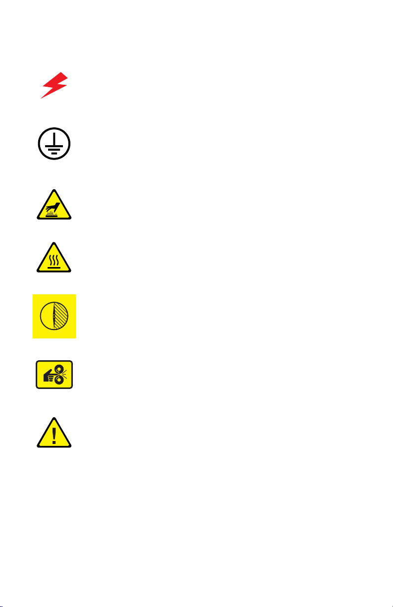
Symbols Marked on the Product
DANGER high voltage.
Protective ground (earth) symbol.
Hot surface on or in the printer. Use caution to avoid personal
injury.
0
30 min.
The surface is hot while the printer is running. After turning off
the power, wait 30 minutes.
Avoid pinching fingers in the printer. Use caution to avoid
personal injury.
Use caution (or draws attention to a particular component).
Refer to the manual(s) for information.
iv Phaser 7400 Color Printer Service Manual
Page 6

Power Safety Precautions
W
Power Source
For 115 VAC printers, do not apply more than 135 volts RMS between the supply
conductors or between either supply conductor and ground. For 230 VAC printers, do
not apply more than 254 volts RMS between the supply conductors or between either
supply conductor and ground. Use only the specified power cord and connector. This
manual assumes that the reader is a qualified service technician.
Plug the three-wire power cord (with grounding prong) into a grounded AC outlet
only. If necessary, contact a licensed electrician to install a properly grounded outlet.
If the product loses its ground connection, contact with conductive parts may cause an
electrical shock. A protective ground connection by way of the grounding conductor
in the power cord is essential for safe operation.
Disconnecting Power
arning
Turning the power off using the power switch does not completely de-energize
the printer. You must also disconnect the power cord from the printer’s AC inlet.
Disconnect the power cord by pulling the plug, not the cord.
Disconnect the power cord in the following cases:
■ if the power cord or plug is frayed or otherwise damaged,
■ if any liquid or foreign material is spilled into the product,
■ if the printer is exposed to any excess moisture,
■ if the printer is dropped or damaged,
■ if you suspect that the product needs servicing or repair,
■ whenever you clean the product.
Safety v
Page 7

Electrostatic Discharge (ESD) Precautions
Some semiconductor components, and the respective sub-assemblies that contain
them, are vulnerable to damage by Electrostatic discharge (ESD). These components
include Integrated Circuits (ICs), Large-Scale Integrated circuits (LSIs), field-effect
transistors and other semiconductor chip components. The following techniques will
reduce the occurrence of component damage caused by static electricity.
Be sure the power is off to the chassis or circuit board, and observe all other safety
precautions.
■ Immediately before handling any semiconductor components assemblies, drain
the electrostatic charge from your body. This can be accomplished by touching an
earth ground source or by wearing a wrist strap device connected to an earth
ground source. Wearing a wrist strap will also prevent accumulation of additional
bodily static charges. Be sure to remove the wrist strap before applying power to
the unit under test to avoid potential shock.
■ After removing a static sensitive assembly from its anti-static bag, place it on a
grounded conductive surface. If the anti-static bag is conductive, you may ground
the bag and use it as a conductive surface.
■ Do not use freon-propelled chemicals. These can generate electrical charges
sufficient to damage some devices.
■ Do not remove a replacement component or electrical sub-assembly from its
protective package until you are ready to install it.
■ Immediately before removing the protective material from the leads of a
replacement device, touch the protective material to the chassis or circuit
assembly into which the device will be installed.
■ Minimize body motions when handling unpacked replacement devices. Motion
such as your clothes brushing together, or lifting a foot from a carpeted floor can
generate enough static electricity to damage an electro-statically sensitive device
■ Handle IC’s and EPROM’s carefully to avoid bending pins.
■ Pay attention to the direction of parts when mounting or inserting them on
Printed Circuit Boards (PCB’s).
vi Phaser 7400 Color Printer Service Manual
Page 8

Service Safety Summary
General Guidelines
For qualified service personnel only: Refer also to the preceding Power Safety
Precautions.
Avoid servicing alone: Do not perform internal service or adjustment of this
product unless another person capable of rendering first aid or resuscitation is present.
Use care when servicing with power: Dangerous voltages may exist at several
points in this product. To avoid personal injury, do not touch exposed connections and
components while power is on. Disconnect power before removing the power supply
shield or replacing components.
Do not wear jewelry: Remove jewelry prior to servicing. Rings, necklaces and
other metallic objects could come into contact with dangerous voltages and currents.
Warning Labels
Read and obey all posted warning labels. Throughout the printer, warning labels are
displayed on potentially dangerous components. As you service the printer, check to
make certain that all warning labels remain in place.
Safety Interlocks
Make sure all covers are in place and all interlock switches are functioning correctly
after you have completed a printer service call. If you bypass an interlock switch
during a service call, use extreme caution when working on or around the printer.
Safety vii
Page 9
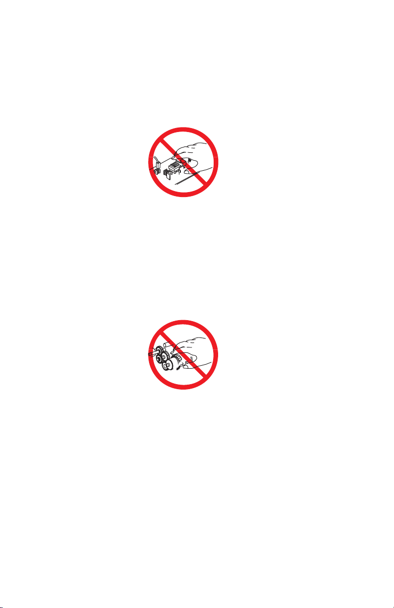
Servicing Electrical Components
W
W
W
Before starting any service procedure, switch off the printer power and unplug the
power cord from the wall outlet. If you must service the printer with power applied,
be aware of the potential for electrical shock.
arning
Do not touch any electrical component unless you are instructed to do so by a
service procedure.
S7300-02
Servicing Mechanical Components
When servicing mechanical components within the printer, manually rotate drive
assemblies, rollers, and gears.
arning
Do not try to manually rotate or manually stop the drive assemblies while any
printer motor is running.
S7300-03
Servicing Fuser Components
arning
This printer uses heat to fuse the toner image to media. The Fuser is VERY HOT.
Turn the printer power off and wait at least 5 minutes for the Fuser to cool before
you attempt to service the Fuser or adjacent components.
viii Phaser 7400 Color Printer Service Manual
Page 10

Regulatory Specifications
Xerox has tested this product to electromagnetic emission and immunity standards.
These standards are designed to mitigate interference caused or received by this
product in a typical office environment.
United States (FCC Regulations)
This equipment has been tested and found to comply with the limits for a Class A
digital device, pursuant to Part 15 of the FCC Rules. These limits are designed to
provide reasonable protection against harmful interference when the equipment is
operated in a commercial environment. This equipment generates, uses, and can
radiate radio frequency energy. If it is not installed and used in accordance with these
instructions, it may cause harmful interference to radio communications. Operation
of this equipment in a residential area is likely to cause harmful interference in which
case the user will be required to correct the interference at his/her own expense.
If this equipment does cause harmful interference to radio or television reception,
which can be determined by turning the equipment off and on, the user is encouraged
to try to correct the interference by one or more of the following measures:
■ Reorient or relocate the receiver.
■ Increase the separation between the equipment and receiver.
■ Connect the equipment into an outlet on a circuit different from that to which the
receiver is connected.
■ Consult the dealer or an experienced radio/television technician for help.
Any changes or modifications not expressly approved by Xerox could void the user's
authority to operate the equipment. To ensure compliance with Part 15 of the FCC
rules, use shielded interface cables.
Canada (Regulations)
This Class A digital apparatus complies with Canadian ICES-003.
Cet appareil numérique de la classe A est conforme à la norme NMB-003 du Canada.
Safety ix
Page 11

European Union
W
arning
This is a class A product. In a domestic environment this product may cause radio
interference in which case the user may be required to take adequate measures.
Xerox Corporation declares, under our sole responsibility, that the product to which
this declaration relates is in conformity with the following standards and other
normative documents:
Low Voltage Directive 73/23/EEC as amended
EN 60950:2000
EN 60825-1:1994+A1:2001+A2:2002
Electromagnetic Compatibility Directive 89/336/EEC as amended
EN 55022:1998 +A1:2000 +A2:2003
EN 55024:1998 +A1:2000 +A2:2003
EN 61000-3-2:2000
EN 61000-3-3:1995 +A1:2001
Radio & Telecommunications Terminal Equipment Directive 1999/5/EC as amended
EN 300 330-2 V1.1.1
EN 300 440-2 V1.1.1
EN 300 489-3 V1.3.1
This product, if used properly in accordance with the user's instructions, is neither
dangerous for the consumer nor for the environment.
A signed copy of the Declaration of Conformity for this product can be obtained from
Xerox.
x Phaser 7400 Color Printer Service Manual
Page 12

Manual Organization
The Phaser 7400 Color Printer Service Manual is the primary document used for
repairing, maintaining, and troubleshooting the printer. The manual is organized into
two books. This volume, Book 1, focuses on the print engine with the exception of
providing complete diagnostic and troubleshooting procedure for the printer and all
its options. Book 2 focuses on option repair and includes an overview of option
theory, option Field Replaceable Unit (FRU) replacement procedures, parts lists, and
wiring diagrams. Use Book 2 after you’ve isolated a problem internal to a specific
option or when a problem arises at the engine/option interface.
Book 1 - Print Engine
Use Book 1 as your primary resource for understanding the operational characteristics
of the print engine. Book 1 describes printer specifications, theory and includes
information important to the diagnosis and repair of problems occurring in the print
engine and attached options. Book 1 also provides detailed print engine replacement
procudures, parts lists, and wiring diagrams.
Book 1 contains these sections:
Introductory, Safety, and Regulatory Information: This section contains
important safety information and regulatory requirements.
Section 1 - General Information: This section contains an overview of the
printer’s operation, configuration, specifications, and consumables.
Section 2 - Theory of Operation: This section contains detailed functional
information on print engine components.
Section 3 - Error Codes and Messages: This section describes the resident
diagnostics available to assist the troubleshooting process. These diagnostics include
error codes and messages and Service Usage Profile data stored in the printer. This
section provides complete troubleshooting information for the print engine and all it’s
options.
Section 4 - General Troubleshooting: Troubleshooting discussions cover the
operation of Power On Self Test (POST), Service Diagnostics, In addition, this
section includes troubleshooting methods for situations where no error indicator is
available.
Section 5 - Print-Quality Troubleshooting: This section focuses on techniques
to correct image quality problems associated with printer output.
Section 6 - Adjustments and Calibrations: This section provides procedures
for the adjustment of print engine components.
Section 7 - Cleaning and Maintenance: This section provides periodic cleaning
procedures for the printer.
Safety xi
Page 13

Section 8 - Service Parts Disassembly: This section contains removal
procedures for spare parts listed in the Parts List. A replacement procedure is included
when necessary.
Section 9 - Parts List: This section contains exploded views of the print engine
and option FRUs, as well as part numbers for orderable parts.
Section 10 - Wiring Diagrams: This section contains the plug/jack locations and
the wiring diagrams for the print engine.
Appendix A - Reference: This section provides an illustration of the printer’s
menu structure, a listing of printer status codes, and a list of Service Diagnostics tests.
Book 2 - Options
Use Book 2 as a reference when servicing printer options. Book 2 includes
information important for the repair or replacement of option components. Use the
troubleshooting procedures in Book 1 to diagnose and isolated the problem.
Book 2 contains these sections:
Introductory, Safety, and Regulatory Information: This section contains
important safety information, regulatory requirements, and information about this
manual.
Section 1 - General Information: This section contains an overview of the
options available, configuration, specifications and consumables.
Section 2 - Theory of Operation: This section contains functional information
on each option.
Section 3 - General Troubleshooting: This this section includes information
and procedures for troubleshooting optional components.
Section 4 - Adjustments and Calibrations: This section provides procedures
for the adjustment of print engine components.
Section 5 - Service Parts Disassembly:
procedures for parts listed in the option’s Field Replaceable Units (FRUs) Parts List.
A replacement procedure is included when necessary.
Section 6 - Parts Lists: This section contains exploded views of the option FRUs,
as well as FRU part numbers.
Section 7 - Wiring Diagrams: This section contains option plug/jack locations
and wiring diagrams.
This section contains removal
xii Phaser 7400 Color Printer Service Manual
Page 14

Contents
Service Terms . . . . . . . . . . . . . . . . . . . . . . . . . . . . . . . . . . . . . . . . . . . . . . iii
Symbols Marked on the Product . . . . . . . . . . . . . . . . . . . . . . . . . . . . . . . . iv
Power Safety Precautions . . . . . . . . . . . . . . . . . . . . . . . . . . . . . . . . . . . . . .v
Electrostatic Discharge (ESD) Precautions. . . . . . . . . . . . . . . . . . . . . . . . . vi
Service Safety Summary . . . . . . . . . . . . . . . . . . . . . . . . . . . . . . . . . . . . . .vii
Regulatory Specifications. . . . . . . . . . . . . . . . . . . . . . . . . . . . . . . . . . . . . . ix
Manual Organization . . . . . . . . . . . . . . . . . . . . . . . . . . . . . . . . . . . . . . . . . xi
1 General Information
Printer Introduction and Overview . . . . . . . . . . . . . . . . . . . . . . . . . . . . . . 1-2
Printer Configurations. . . . . . . . . . . . . . . . . . . . . . . . . . . . . . . . . . 1-3
Metered Printing. . . . . . . . . . . . . . . . . . . . . . . . . . . . . . . . . . . . . . 1-4
Parts of the Printer . . . . . . . . . . . . . . . . . . . . . . . . . . . . . . . . . . . . 1-5
Control Panel . . . . . . . . . . . . . . . . . . . . . . . . . . . . . . . . . . . . . . . . 1-7
Image Processor Board . . . . . . . . . . . . . . . . . . . . . . . . . . . . . . . . 1-8
Printer Options. . . . . . . . . . . . . . . . . . . . . . . . . . . . . . . . . . . . . . . . . . . . . 1-9
Hard Drive. . . . . . . . . . . . . . . . . . . . . . . . . . . . . . . . . . . . . . . . . . . 1-9
Additional Memory . . . . . . . . . . . . . . . . . . . . . . . . . . . . . . . . . . . . 1-9
Configuration Card . . . . . . . . . . . . . . . . . . . . . . . . . . . . . . . . . . . 1-10
550-Sheet Feeder . . . . . . . . . . . . . . . . . . . . . . . . . . . . . . . . . . . . 1-10
1650-Sheet Feeder . . . . . . . . . . . . . . . . . . . . . . . . . . . . . . . . . . . 1-10
Duplex Unit. . . . . . . . . . . . . . . . . . . . . . . . . . . . . . . . . . . . . . . . . 1-11
Finisher. . . . . . . . . . . . . . . . . . . . . . . . . . . . . . . . . . . . . . . . . . . . 1-11
Maintenance Items. . . . . . . . . . . . . . . . . . . . . . . . . . . . . . . . . . . . . . . . . 1-12
Consumables . . . . . . . . . . . . . . . . . . . . . . . . . . . . . . . . . . . . . . . . . . . . . 1-12
Specifications. . . . . . . . . . . . . . . . . . . . . . . . . . . . . . . . . . . . . . . . . . . . . 1-13
Memory Specifications. . . . . . . . . . . . . . . . . . . . . . . . . . . . . . . . 1-13
Consumable Life Specifications . . . . . . . . . . . . . . . . . . . . . . . . . 1-13
Electrical Specifications . . . . . . . . . . . . . . . . . . . . . . . . . . . . . . . 1-14
Physical Dimensions and Clearances . . . . . . . . . . . . . . . . . . . . . 1-14
Functional Specifications . . . . . . . . . . . . . . . . . . . . . . . . . . . . . . 1-16
First Print Output Time . . . . . . . . . . . . . . . . . . . . . . . . . . . . . . . . 1-16
Image Specifications. . . . . . . . . . . . . . . . . . . . . . . . . . . . . . . . . . 1-17
Environmental Specifications . . . . . . . . . . . . . . . . . . . . . . . . . . . 1-17
Media and Tray Specifications . . . . . . . . . . . . . . . . . . . . . . . . . . 1-18
Contents xiii
Page 15

2 Theory of Operation
Phaser 7400 Operational Overview . . . . . . . . . . . . . . . . . . . . . . . . . . . . . 2-2
Imaging Unit . . . . . . . . . . . . . . . . . . . . . . . . . . . . . . . . . . . . . . . . 2-3
LED Heads . . . . . . . . . . . . . . . . . . . . . . . . . . . . . . . . . . . . . . . . . . 2-4
Fuser . . . . . . . . . . . . . . . . . . . . . . . . . . . . . . . . . . . . . . . . . . . . . . 2-4
Transfer Unit . . . . . . . . . . . . . . . . . . . . . . . . . . . . . . . . . . . . . . . . 2-5
Print Process Summary . . . . . . . . . . . . . . . . . . . . . . . . . . . . . . . . . . . . . 2-6
Printer Controls. . . . . . . . . . . . . . . . . . . . . . . . . . . . . . . . . . . . . . . . . . . 2-10
Print-Quality Modes. . . . . . . . . . . . . . . . . . . . . . . . . . . . . . . . . . 2-10
Color Registration Control . . . . . . . . . . . . . . . . . . . . . . . . . . . . . 2-10
Automatic Density Control. . . . . . . . . . . . . . . . . . . . . . . . . . . . . 2-13
Selective Control: Paper Pick. . . . . . . . . . . . . . . . . . . . . . . . . . . 2-13
Image Transfer Control . . . . . . . . . . . . . . . . . . . . . . . . . . . . . . . 2-14
Fuser Temperature Control . . . . . . . . . . . . . . . . . . . . . . . . . . . . 2-14
Consumable Control . . . . . . . . . . . . . . . . . . . . . . . . . . . . . . . . . 2-14
Sensors. . . . . . . . . . . . . . . . . . . . . . . . . . . . . . . . . . . . . . . . . . . . . . . . . 2-15
Sensor Types. . . . . . . . . . . . . . . . . . . . . . . . . . . . . . . . . . . . . . . 2-15
Sensors in the Printer . . . . . . . . . . . . . . . . . . . . . . . . . . . . . . . . 2-17
Sensor Functions. . . . . . . . . . . . . . . . . . . . . . . . . . . . . . . . . . . . 2-19
Paper Level Detection . . . . . . . . . . . . . . . . . . . . . . . . . . . . . . . . 2-21
Paper Present Detection . . . . . . . . . . . . . . . . . . . . . . . . . . . . . . 2-21
Transparent Media Detection. . . . . . . . . . . . . . . . . . . . . . . . . . . 2-21
Automatic Media Thickness Detection . . . . . . . . . . . . . . . . . . . . 2-21
Paper Size Detection . . . . . . . . . . . . . . . . . . . . . . . . . . . . . . . . . 2-22
Jam Detection . . . . . . . . . . . . . . . . . . . . . . . . . . . . . . . . . . . . . . 2-23
Interlock Detection. . . . . . . . . . . . . . . . . . . . . . . . . . . . . . . . . . . 2-24
Toner Detection . . . . . . . . . . . . . . . . . . . . . . . . . . . . . . . . . . . . . 2-24
Input Paper Path . . . . . . . . . . . . . . . . . . . . . . . . . . . . . . . . . . . . . . . . . . 2-27
Paper Fed from Tray 1 (MPT) . . . . . . . . . . . . . . . . . . . . . . . . . . 2-27
Paper Fed from Tray 2 . . . . . . . . . . . . . . . . . . . . . . . . . . . . . . . . 2-30
Paper Fed from Optional Trays . . . . . . . . . . . . . . . . . . . . . . . . . 2-33
Duplex Unit . . . . . . . . . . . . . . . . . . . . . . . . . . . . . . . . . . . . . . . . 2-35
Output Paper Path. . . . . . . . . . . . . . . . . . . . . . . . . . . . . . . . . . . . . . . . . 2-37
Fuser and Exit . . . . . . . . . . . . . . . . . . . . . . . . . . . . . . . . . . . . . . 2-37
Top Output Tray. . . . . . . . . . . . . . . . . . . . . . . . . . . . . . . . . . . . . 2-38
Side Output Tray . . . . . . . . . . . . . . . . . . . . . . . . . . . . . . . . . . . . 2-38
Finisher/Inverter. . . . . . . . . . . . . . . . . . . . . . . . . . . . . . . . . . . . . 2-38
Drive Assemblies. . . . . . . . . . . . . . . . . . . . . . . . . . . . . . . . . . . . . . . . . . 2-39
Imaging Unit Drive Motors. . . . . . . . . . . . . . . . . . . . . . . . . . . . . 2-39
Transfer Unit Motor . . . . . . . . . . . . . . . . . . . . . . . . . . . . . . . . . . 2-41
Fuser Motor . . . . . . . . . . . . . . . . . . . . . . . . . . . . . . . . . . . . . . . . 2-43
Toner Dispense Motors . . . . . . . . . . . . . . . . . . . . . . . . . . . . . . . 2-44
Duplex Drive Motors . . . . . . . . . . . . . . . . . . . . . . . . . . . . . . . . . 2-45
xiv Phaser 7400 Color Printer Service Manual
Page 16

Chassis Assemblies . . . . . . . . . . . . . . . . . . . . . . . . . . . . . . . . . . . . . . . . 2-46
Basket Assembly. . . . . . . . . . . . . . . . . . . . . . . . . . . . . . . . . . . . . 2-46
Waste Toner Recovery . . . . . . . . . . . . . . . . . . . . . . . . . . . . . . . . 2-47
Registration Assembly . . . . . . . . . . . . . . . . . . . . . . . . . . . . . . . . 2-48
Exit Assembly. . . . . . . . . . . . . . . . . . . . . . . . . . . . . . . . . . . . . . . 2-49
Job Offset Assembly. . . . . . . . . . . . . . . . . . . . . . . . . . . . . . . . . . 2-51
Trays . . . . . . . . . . . . . . . . . . . . . . . . . . . . . . . . . . . . . . . . . . . . . . . . . . . 2-52
Tray 1 (MPT) . . . . . . . . . . . . . . . . . . . . . . . . . . . . . . . . . . . . . . . 2-52
Universal Trays. . . . . . . . . . . . . . . . . . . . . . . . . . . . . . . . . . . . . . 2-53
Universal Feeder . . . . . . . . . . . . . . . . . . . . . . . . . . . . . . . . . . . . . 2-54
Side Output Tray. . . . . . . . . . . . . . . . . . . . . . . . . . . . . . . . . . . . . 2-54
Electrical. . . . . . . . . . . . . . . . . . . . . . . . . . . . . . . . . . . . . . . . . . . . . . . . . 2-55
Control Panel . . . . . . . . . . . . . . . . . . . . . . . . . . . . . . . . . . . . . . . 2-56
Image Processor Board . . . . . . . . . . . . . . . . . . . . . . . . . . . . . . . 2-56
Engine Control Board . . . . . . . . . . . . . . . . . . . . . . . . . . . . . . . . . 2-56
Registration Sensor Board . . . . . . . . . . . . . . . . . . . . . . . . . . . . . 2-56
LED Relay Board. . . . . . . . . . . . . . . . . . . . . . . . . . . . . . . . . . . . . 2-56
Imaging Unit Sensor Board. . . . . . . . . . . . . . . . . . . . . . . . . . . . . 2-57
Motor Driver Board. . . . . . . . . . . . . . . . . . . . . . . . . . . . . . . . . . . 2-57
Feeder Board. . . . . . . . . . . . . . . . . . . . . . . . . . . . . . . . . . . . . . . . 2-57
HVPS . . . . . . . . . . . . . . . . . . . . . . . . . . . . . . . . . . . . . . . . . . . . . 2-58
LVPS. . . . . . . . . . . . . . . . . . . . . . . . . . . . . . . . . . . . . . . . . . . . . . 2-59
Front Sensor Board. . . . . . . . . . . . . . . . . . . . . . . . . . . . . . . . . . . 2-59
Rear Sensor Board . . . . . . . . . . . . . . . . . . . . . . . . . . . . . . . . . . . 2-59
Fans . . . . . . . . . . . . . . . . . . . . . . . . . . . . . . . . . . . . . . . . . . . . . . 2-60
Solenoids and Clutches . . . . . . . . . . . . . . . . . . . . . . . . . . . . . . . 2-61
3 Error Messages and Codes
Introduction . . . . . . . . . . . . . . . . . . . . . . . . . . . . . . . . . . . . . . . . . . . . . . . 3-2
Accessing Fault History . . . . . . . . . . . . . . . . . . . . . . . . . . . . . . . . 3-2
Status Page. . . . . . . . . . . . . . . . . . . . . . . . . . . . . . . . . . . . . . . . . . 3-3
Service Usage Profile . . . . . . . . . . . . . . . . . . . . . . . . . . . . . . . . . . 3-3
Servicing Instructions . . . . . . . . . . . . . . . . . . . . . . . . . . . . . . . . . . . . . . . 3-4
Messages, Codes, and Procedures . . . . . . . . . . . . . . . . . . . . . . . . . . . . . 3-5
Error Message Abbreviations . . . . . . . . . . . . . . . . . . . . . . . . . . . . 3-5
Jam Locator . . . . . . . . . . . . . . . . . . . . . . . . . . . . . . . . . . . . . . . . . 3-6
Error Message Summary . . . . . . . . . . . . . . . . . . . . . . . . . . . . . . . 3-7
Using the Troubleshooting Procedures. . . . . . . . . . . . . . . . . . . . 3-15
Measurement Techniques. . . . . . . . . . . . . . . . . . . . . . . . . . . . . . 3-16
Jam Error Procedures . . . . . . . . . . . . . . . . . . . . . . . . . . . . . . . . . . . . . . 3-17
Jam at Door A Open Door A to Clear . . . . . . . . . . . . . . . . . . . . . 3-17
Jam at Door A Open Door A to Clear . . . . . . . . . . . . . . . . . . . . . 3-19
Jam at Door A Misfeed at Tray 1 (MPT) . . . . . . . . . . . . . . . . . . . 3-20
Jam at Door B Misfeed at Tray 2. . . . . . . . . . . . . . . . . . . . . . . . . 3-21
Jam at Door C for Tray [3][4][5][6] . . . . . . . . . . . . . . . . . . . . . . 3-23
Jam at Door D Open Door D to Clear . . . . . . . . . . . . . . . . . . . . . 3-25
Contents xv
Page 17

Jam in Duplex Unit. . . . . . . . . . . . . . . . . . . . . . . . . . . . . . . . . . . 3-26
Jam at Door E . . . . . . . . . . . . . . . . . . . . . . . . . . . . . . . . . . . . . . 3-27
Jam Under Imaging Units . . . . . . . . . . . . . . . . . . . . . . . . . . . . . 3-29
Jam in Fuser . . . . . . . . . . . . . . . . . . . . . . . . . . . . . . . . . . . . . . . 3-31
Jam at Duplex Entrance . . . . . . . . . . . . . . . . . . . . . . . . . . . . . . . 3-33
Jam at Finisher Punch Unit . . . . . . . . . . . . . . . . . . . . . . . . . . . . 3-35
Jam at Finisher Door H . . . . . . . . . . . . . . . . . . . . . . . . . . . . . . . 3-36
Jam at Finisher Door H . . . . . . . . . . . . . . . . . . . . . . . . . . . . . . . 3-37
Jam at Finisher Upper Output Tray . . . . . . . . . . . . . . . . . . . . . . 3-38
Jam at Finisher Saddle Stapler. . . . . . . . . . . . . . . . . . . . . . . . . . 3-39
Jam at Finisher Upper Output Tray . . . . . . . . . . . . . . . . . . . . . . 3-40
Jam at Finisher Stapler . . . . . . . . . . . . . . . . . . . . . . . . . . . . . . . 3-41
Jam at Finisher Door G . . . . . . . . . . . . . . . . . . . . . . . . . . . . . . . 3-42
Jam at Finisher Saddle Stapler. . . . . . . . . . . . . . . . . . . . . . . . . . 3-43
Jam at Finisher Upper Output Tray . . . . . . . . . . . . . . . . . . . . . . 3-44
Jam Inside Finisher . . . . . . . . . . . . . . . . . . . . . . . . . . . . . . . . . . 3-45
Jam at Finisher Entrance . . . . . . . . . . . . . . . . . . . . . . . . . . . . . . 3-46
Finisher Output Tray Jammed . . . . . . . . . . . . . . . . . . . . . . . . . . 3-47
Door and Cover Errors. . . . . . . . . . . . . . . . . . . . . . . . . . . . . . . . . . . . . . 3-49
Close Top Cover. . . . . . . . . . . . . . . . . . . . . . . . . . . . . . . . . . . . . 3-49
Close Right Door A . . . . . . . . . . . . . . . . . . . . . . . . . . . . . . . . . . 3-50
Close Right Door B . . . . . . . . . . . . . . . . . . . . . . . . . . . . . . . . . . 3-51
Close Right Door C for Tray [3][4][5][6] . . . . . . . . . . . . . . . . . . 3-53
Close Left Door D. . . . . . . . . . . . . . . . . . . . . . . . . . . . . . . . . . . . 3-54
Close Left Door E. . . . . . . . . . . . . . . . . . . . . . . . . . . . . . . . . . . . 3-55
Close Finisher Door F. . . . . . . . . . . . . . . . . . . . . . . . . . . . . . . . . 3-56
Close Finisher Door H . . . . . . . . . . . . . . . . . . . . . . . . . . . . . . . . 3-57
Close Finisher Door J. . . . . . . . . . . . . . . . . . . . . . . . . . . . . . . . . 3-58
Consumable/Routine Maintenance Procedures . . . . . . . . . . . . . . . . . . . 3-59
Replace [C][M][Y][K] Toner Cartridge . . . . . . . . . . . . . . . . . . . . 3-59
Replace [C][M][Y][K] Imaging Unit. . . . . . . . . . . . . . . . . . . . . . 3-60
Replace Transfer Unit . . . . . . . . . . . . . . . . . . . . . . . . . . . . . . . . 3-61
Replace Waste Cartridge . . . . . . . . . . . . . . . . . . . . . . . . . . . . . . 3-62
Replace Fuser . . . . . . . . . . . . . . . . . . . . . . . . . . . . . . . . . . . . . . 3-63
Install, Reseat or Lock [C][M][Y][K] Toner Cartridge . . . . . . . . 3-64
Install or Reseat [C][M][Y][K] Imaging Unit . . . . . . . . . . . . . . . 3-65
Install or Reseat Transfer Unit . . . . . . . . . . . . . . . . . . . . . . . . . . 3-66
Install or Reseat Waste Cartridge. . . . . . . . . . . . . . . . . . . . . . . . 3-67
Install or Reseat Fuser . . . . . . . . . . . . . . . . . . . . . . . . . . . . . . . . 3-68
Metered Toner Is not Enabled . . . . . . . . . . . . . . . . . . . . . . . . . . 3-69
Replace Metered [C][M][Y][K] Toner Cartridge . . . . . . . . . . . . . 3-70
xvi Phaser 7400 Color Printer Service Manual
Page 18

Tray and Media Errors . . . . . . . . . . . . . . . . . . . . . . . . . . . . . . . . . . . . . . 3-71
Clear Tray 1 (MPT) Riser Plate . . . . . . . . . . . . . . . . . . . . . . . . . . 3-71
Clear Tray [2][3][4][5][6] Riser Plate . . . . . . . . . . . . . . . . . . . . . 3-73
Out of Paper Load Tray 1(MPT) with [size] [type] . . . . . . . . . . . 3-74
Out of Paper Load Tray [2][3][4][5][6] with [size][type] . . . . . . 3-75
Manual Feed [size][type] . . . . . . . . . . . . . . . . . . . . . . . . . . . . . . 3-76
Top Output Tray Is Full, Unload Paper . . . . . . . . . . . . . . . . . . . .3-77
Left Side Output Tray Is Full, Unload Paper . . . . . . . . . . . . . . . . 3-78
Finisher Lower Output Tray is Full, Unload Paper . . . . . . . . . . . . 3-79
Finisher Upper Output Tray is Full, Unload Paper . . . . . . . . . . . . 3-80
Open Left Side Output Tray. . . . . . . . . . . . . . . . . . . . . . . . . . . . . 3-81
Media Mismatch Errors . . . . . . . . . . . . . . . . . . . . . . . . . . . . . . . . . . . . . 3-82
Wrong Paper Size; Load Tray 1 (MPT) with [size][type]. . . . . . . 3-82
Wrong Paper Size; Load Tray 2 with [size][type] . . . . . . . . . . . . 3-83
Wrong Paper Size; Load Tray [3][4][5][6] with [size][type]. . . . 3-84
Wrong Paper Type Load Tray [1 (MPT)][2][3][4][5][6] with
[size][type] . . . . . . . . . . . . . . . . . . . . . . . . . . . . . . . . . . . . . . 3-85
Paper Not Available Load Tray 1 (MPT) with [size] [type] . . . . . 3-86
Paper Not Available; Load Tray 2 with [size][type] . . . . . . . . . . . 3-87
Paper Not Available Load Tray [3][4][5][6] with [size][type] . . . 3-88
Configuration Errors. . . . . . . . . . . . . . . . . . . . . . . . . . . . . . . . . . . . . . . . 3-89
Invalid or Missing Configuration Card . . . . . . . . . . . . . . . . . . . . 3-89
Duplicate IP Address Detected . . . . . . . . . . . . . . . . . . . . . . . . . . 3-89
Fatal Error Procedures . . . . . . . . . . . . . . . . . . . . . . . . . . . . . . . . . . . . . . 3-90
Fuser Failure. . . . . . . . . . . . . . . . . . . . . . . . . . . . . . . . . . . . . . . . 3-90
Temp Sensor Failure. . . . . . . . . . . . . . . . . . . . . . . . . . . . . . . . . . 3-92
RH Sensor Failure. . . . . . . . . . . . . . . . . . . . . . . . . . . . . . . . . . . . 3-93
LED Over Temperature Failure . . . . . . . . . . . . . . . . . . . . . . . . . . 3-94
Motor Overheating Failure . . . . . . . . . . . . . . . . . . . . . . . . . . . . . 3-95
Engine Failure. . . . . . . . . . . . . . . . . . . . . . . . . . . . . . . . . . . . . . . 3-96
Power Supply Failure . . . . . . . . . . . . . . . . . . . . . . . . . . . . . . . . . 3-97
Feeder Home Failure. . . . . . . . . . . . . . . . . . . . . . . . . . . . . . . . . . 3-98
Controller Fan Failure . . . . . . . . . . . . . . . . . . . . . . . . . . . . . . . . . 3-99
Power Supply Fan Failure . . . . . . . . . . . . . . . . . . . . . . . . . . . . . 3-100
Top Cover Cooling Fan Failure . . . . . . . . . . . . . . . . . . . . . . . . . 3-101
Imaging Unit Fan Failure. . . . . . . . . . . . . . . . . . . . . . . . . . . . . . 3-102
Transfer Unit Fan Failure. . . . . . . . . . . . . . . . . . . . . . . . . . . . . . 3-103
Engine Cavity Fan Failure . . . . . . . . . . . . . . . . . . . . . . . . . . . . . 3-104
Duplex Interface Failure . . . . . . . . . . . . . . . . . . . . . . . . . . . . . . 3-105
Tray [3][4][5][6] Interface Failure. . . . . . . . . . . . . . . . . . . . . . . 3-106
Inverter Unit Interface Failure . . . . . . . . . . . . . . . . . . . . . . . . . . 3-107
[C][M][Y][K] LED Failure . . . . . . . . . . . . . . . . . . . . . . . . . . . . . 3-108
[C][M][Y][K] Imaging Unit Failure . . . . . . . . . . . . . . . . . . . . . . 3-109
Flash Failure . . . . . . . . . . . . . . . . . . . . . . . . . . . . . . . . . . . . . . . 3-111
Fuser Fan Failure. . . . . . . . . . . . . . . . . . . . . . . . . . . . . . . . . . . . 3-112
Fuser 110v/220v Mismatch Failure. . . . . . . . . . . . . . . . . . . . . . 3-113
Contents xvii
Page 19

Unsupported Duplex Unit ROM . . . . . . . . . . . . . . . . . . . . . . . . 3-114
Unsupported Tray 2 ROM . . . . . . . . . . . . . . . . . . . . . . . . . . . . 3-115
Unsupported Tray [3][4][5][6] ROM . . . . . . . . . . . . . . . . . . . . 3-116
Unsupported Inverter Unit ROM . . . . . . . . . . . . . . . . . . . . . . . 3-117
Unsupported Finisher Unit ROM . . . . . . . . . . . . . . . . . . . . . . . 3-118
Hard Drive Failure . . . . . . . . . . . . . . . . . . . . . . . . . . . . . . . . . . 3-119
Fuse Cut Error In Fuser . . . . . . . . . . . . . . . . . . . . . . . . . . . . . . 3-120
Fuse Cut Error In Transfer Unit . . . . . . . . . . . . . . . . . . . . . . . . 3-121
Fuse Cut Error In [C][M][Y][K] Imaging Unit. . . . . . . . . . . . . . 3-122
Controller to Engine Communications Failure . . . . . . . . . . . . . 3-123
Finisher Fold Position Sensor Failure. . . . . . . . . . . . . . . . . . . . 3-124
Finisher Paddle Failure. . . . . . . . . . . . . . . . . . . . . . . . . . . . . . . 3-125
Finisher Stapler Swing Motor Failure . . . . . . . . . . . . . . . . . . . . 3-126
Finisher Stack Handling Motor Failure . . . . . . . . . . . . . . . . . . . 3-127
Finisher Staple Motor Failure. . . . . . . . . . . . . . . . . . . . . . . . . . 3-128
Finisher Jog Motor Failure. . . . . . . . . . . . . . . . . . . . . . . . . . . . 3-129
Finisher Lift Motor Failure . . . . . . . . . . . . . . . . . . . . . . . . . . . . 3-130
Finisher Exit Failure . . . . . . . . . . . . . . . . . . . . . . . . . . . . . . . . . 3-132
Finisher Punch Side Registration Sensor Failure . . . . . . . . . . . 3-133
Finisher Punch Registration Sensor Failure . . . . . . . . . . . . . . . 3-134
Finisher Punch Backup RAM Failure . . . . . . . . . . . . . . . . . . . . 3-135
Finisher Punch Communications Failure . . . . . . . . . . . . . . . . . 3-136
Finisher Punch Unit Transfer Motor Failure . . . . . . . . . . . . . . . 3-137
Finisher Punch Motor Failure. . . . . . . . . . . . . . . . . . . . . . . . . . 3-138
Finisher Backup RAM Failure. . . . . . . . . . . . . . . . . . . . . . . . . . 3-139
Finisher Punch Dust Sensor Failure. . . . . . . . . . . . . . . . . . . . . 3-140
Printer Error - Contact Service; report fault [n]. . . . . . . . . . . . . . . . . . 3-141
Finisher Punch Unit Counter at End of Life . . . . . . . . . . . . . . . 3-141
Finisher Staple Unit Counter at End of Life. . . . . . . . . . . . . . . . 3-142
Finisher Interface Error . . . . . . . . . . . . . . . . . . . . . . . . . . . . . . 3-143
Inverter Power Supply Failure . . . . . . . . . . . . . . . . . . . . . . . . . 3-144
Fuser Thermistor Errors. . . . . . . . . . . . . . . . . . . . . . . . . . . . . . 3-145
Job Offset Home Position Error. . . . . . . . . . . . . . . . . . . . . . . . 3-146
Control Panel Communications Failure . . . . . . . . . . . . . . . . . . 3-147
No Data to the [C][M][Y][K] LED Head . . . . . . . . . . . . . . . . . . 3-148
Motor Driver Board Communications Error . . . . . . . . . . . . . . . 3-149
Tray [3][4][5][6] Firmware Error . . . . . . . . . . . . . . . . . . . . . . . 3-150
Duplex Unit Firmware Error . . . . . . . . . . . . . . . . . . . . . . . . . . . 3-151
Motor Driver Board Firmware Error . . . . . . . . . . . . . . . . . . . . . 3-152
Finisher Inverter Firmware Error . . . . . . . . . . . . . . . . . . . . . . . 3-153
CRUM Reader Board Failure . . . . . . . . . . . . . . . . . . . . . . . . . . 3-154
Tray [3][4][5][6] Flash Memory Failure . . . . . . . . . . . . . . . . . . 3-155
Duplex Unit Flash Memory Failure . . . . . . . . . . . . . . . . . . . . . . 3-156
Motor Driver Board Flash Memory Failure . . . . . . . . . . . . . . . . 3-157
Finisher Inverter Flash Memory Failure . . . . . . . . . . . . . . . . . . 3-158
Tray 2 Lift Motor Failure . . . . . . . . . . . . . . . . . . . . . . . . . . . . . 3-159
xviii Phaser 7400 Color Printer Service Manual
Page 20

Tray [3][4][5][6] Lift Motor Failure. . . . . . . . . . . . . . . . . . . . . . 3-160
Error in the Transfer Unit Belt. . . . . . . . . . . . . . . . . . . . . . . . . . 3-162
Duplex Unit Fan Failure. . . . . . . . . . . . . . . . . . . . . . . . . . . . . . . 3-163
+24V Not Available to the Duplex Unit . . . . . . . . . . . . . . . . . . . 3-164
Failure in the [C][M][Y][K] Imaging Unit Drum or Motor . . . . . 3-165
+24 V Not Available to Tray [3][4][5][6]. . . . . . . . . . . . . . . . . . 3-167
Failure in the Fuser Motor. . . . . . . . . . . . . . . . . . . . . . . . . . . . . 3-168
Failure in the Waste Toner Motor . . . . . . . . . . . . . . . . . . . . . . . 3-169
Motor Driver Board Clock Frequency Error. . . . . . . . . . . . . . . . 3-170
Duplex Unit Clock Frequency Error. . . . . . . . . . . . . . . . . . . . . . 3-171
Finisher Inverter Clock Frequency Error . . . . . . . . . . . . . . . . . . 3-172
Tray [3][4][5][6] Feeder Board Clock Frequency Error . . . . . . . 3-173
Waste Toner Transfer Error . . . . . . . . . . . . . . . . . . . . . . . . . . . 3-174
[CM][YK] Toner Supply Failure. . . . . . . . . . . . . . . . . . . . . . . . . 3-176
Warning Messages. . . . . . . . . . . . . . . . . . . . . . . . . . . . . . . . . . . . . . . . 3-177
No Paper in Tray 1 (MPT). . . . . . . . . . . . . . . . . . . . . . . . . . . . . 3-177
No Paper in Tray [2][3][4][5][6]. . . . . . . . . . . . . . . . . . . . . . . . 3-178
Left Side Output Tray is Closed. . . . . . . . . . . . . . . . . . . . . . . . . 3-179
Waste Cartridge is Almost Full . . . . . . . . . . . . . . . . . . . . . . . . . 3-180
Non-Xerox [C][M][Y][K] Toner Cartridge . . . . . . . . . . . . . . . . . 3-181
Staple Cartridge Is Empty. . . . . . . . . . . . . . . . . . . . . . . . . . . . . 3-182
Punch Waste Box is Full or Missing . . . . . . . . . . . . . . . . . . . . . 3-183
Finisher Away From Base . . . . . . . . . . . . . . . . . . . . . . . . . . . . . 3-184
Finisher Away From Printer. . . . . . . . . . . . . . . . . . . . . . . . . . . . 3-185
4 General Troubleshooting
Introduction . . . . . . . . . . . . . . . . . . . . . . . . . . . . . . . . . . . . . . . . . . . . . . . 4-2
System Startup . . . . . . . . . . . . . . . . . . . . . . . . . . . . . . . . . . . . . . . . . . . . 4-2
Power On Self Test (POST) . . . . . . . . . . . . . . . . . . . . . . . . . . . . . . . . . . . 4-3
POST Soft Fault Messages . . . . . . . . . . . . . . . . . . . . . . . . . . . . . . 4-4
POST Hard Fault Messages. . . . . . . . . . . . . . . . . . . . . . . . . . . . . . 4-5
Fault Isolation. . . . . . . . . . . . . . . . . . . . . . . . . . . . . . . . . . . . . . . . . . . . . . 4-6
Entry Level Fault Isolation Procedure . . . . . . . . . . . . . . . . . . . . . . 4-6
Service Diagnostics . . . . . . . . . . . . . . . . . . . . . . . . . . . . . . . . . . . . . . . . . 4-7
Using Service Diagnostics . . . . . . . . . . . . . . . . . . . . . . . . . . . . . . 4-7
Service Diagnostics Controls . . . . . . . . . . . . . . . . . . . . . . . . . . . . 4-8
Service Diagnostics Utilities . . . . . . . . . . . . . . . . . . . . . . . . . . . . . 4-9
Status . . . . . . . . . . . . . . . . . . . . . . . . . . . . . . . . . . . . . . . . . . . . . . 4-9
Test Prints . . . . . . . . . . . . . . . . . . . . . . . . . . . . . . . . . . . . . . . . . 4-10
Control Panel Troubleshooting. . . . . . . . . . . . . . . . . . . . . . . . . . . . . . . . 4-10
No Control Panel Display after Power Is Turned On . . . . . . . . . . 4-10
Control Panel LED Is On, Control Panel Display Is Blank . . . . . . 4-11
Contents xix
Page 21

Inoperable Printer Troubleshooting. . . . . . . . . . . . . . . . . . . . . . . . . . . . 4-11
Engine Power-Up Sequence (BIST) . . . . . . . . . . . . . . . . . . . . . . 4-12
Printer Continually Displays Warming Up.... . . . . . . . . . . . . . . . 4-13
Printer Displays Install or Reseat Imaging Unit . . . . . . . . . . . . . 4-13
Printer Displays Reseat Contoller Board . . . . . . . . . . . . . . . . . . 4-13
Printer Does Not Come to a Ready State . . . . . . . . . . . . . . . . . . 4-14
Paper Size Switch Assembly . . . . . . . . . . . . . . . . . . . . . . . . . . . . . . . . . 4-14
Power Supply . . . . . . . . . . . . . . . . . . . . . . . . . . . . . . . . . . . . . . . . . . . . 4-16
AC Power Supply Troubleshooting . . . . . . . . . . . . . . . . . . . . . . . . . . . . 4-16
DC Power Supply Troubleshooting . . . . . . . . . . . . . . . . . . . . . . . . . . . . 4-17
RAM Memory Fault Isolation. . . . . . . . . . . . . . . . . . . . . . . . . . . . . . . . . 4-17
Media Jams and the Paper Path . . . . . . . . . . . . . . . . . . . . . . . . . . . . . . 4-19
Operating System and Application Problems . . . . . . . . . . . . . . . . . . . . 4-21
Macintosh Printing Problems . . . . . . . . . . . . . . . . . . . . . . . . . . 4-21
Windows Printing Problems . . . . . . . . . . . . . . . . . . . . . . . . . . . 4-23
Network Problems. . . . . . . . . . . . . . . . . . . . . . . . . . . . . . . . . . . . . . . . . 4-24
Network Diagnostics . . . . . . . . . . . . . . . . . . . . . . . . . . . . . . . . . 4-24
Network Logging . . . . . . . . . . . . . . . . . . . . . . . . . . . . . . . . . . . . 4-26
USB Port Testing . . . . . . . . . . . . . . . . . . . . . . . . . . . . . . . . . . . . 4-27
5 Print-Quality Troubleshooting
Print-Quality Problems Overview. . . . . . . . . . . . . . . . . . . . . . . . . . . . . . . 5-2
Defects Associated with Specific Printer Components. . . . . . . . . 5-3
Test Prints. . . . . . . . . . . . . . . . . . . . . . . . . . . . . . . . . . . . . . . . . . . . . . . . 5-4
Analyzing the 100% Solid Fill Pages . . . . . . . . . . . . . . . . . . . . . . 5-4
Analyzing the Color Test Pages . . . . . . . . . . . . . . . . . . . . . . . . . . 5-5
Analyzing the PS Pattern . . . . . . . . . . . . . . . . . . . . . . . . . . . . . . . 5-6
Analyzing the Color Step Pages . . . . . . . . . . . . . . . . . . . . . . . . . . 5-7
Print-Quality Troubleshooting . . . . . . . . . . . . . . . . . . . . . . . . . . . . . . . . . 5-8
Light Prints in All Colors . . . . . . . . . . . . . . . . . . . . . . . . . . . . . . . 5-8
Light Print in Only One Color. . . . . . . . . . . . . . . . . . . . . . . . . . . 5-10
Blank Prints . . . . . . . . . . . . . . . . . . . . . . . . . . . . . . . . . . . . . . . . 5-12
Mottled or Splotchy Prints. . . . . . . . . . . . . . . . . . . . . . . . . . . . . 5-14
Unexpected Colors. . . . . . . . . . . . . . . . . . . . . . . . . . . . . . . . . . . 5-16
Repeating Bands, Lines, Marks, or Spots . . . . . . . . . . . . . . . . . 5-18
Random Bands, Lines, Marks, or Missing Spots . . . . . . . . . . . . 5-19
Random Spots. . . . . . . . . . . . . . . . . . . . . . . . . . . . . . . . . . . . . . 5-21
Background Contamination . . . . . . . . . . . . . . . . . . . . . . . . . . . . 5-23
Residual Image, Ghosting or Hot Offset. . . . . . . . . . . . . . . . . . . 5-25
Incomplete Fusing or Cold Offset. . . . . . . . . . . . . . . . . . . . . . . . 5-27
Mis-Registration, Color Layers Not Correctly Registered. . . . . . 5-28
Toner on Back of Print. . . . . . . . . . . . . . . . . . . . . . . . . . . . . . . . 5-31
Image Not Centered or Positioned Correctly . . . . . . . . . . . . . . . 5-32
Process Direction Bands, Voids, or Streaks. . . . . . . . . . . . . . . . 5-34
Scan Direction Bands, Voids, or Streaks . . . . . . . . . . . . . . . . . . 5-35
Scan Direction Dark Streaks . . . . . . . . . . . . . . . . . . . . . . . . . . . 5-37
Process Direction Bands, Voids, or Streaks. . . . . . . . . . . . . . . . 5-38
xx Phaser 7400 Color Printer Service Manual
Page 22

6 Adjustments and Calibrations
Calibrations . . . . . . . . . . . . . . . . . . . . . . . . . . . . . . . . . . . . . . . . . . . . . . . 6-2
Color Calibration. . . . . . . . . . . . . . . . . . . . . . . . . . . . . . . . . . . . . . 6-2
Margin Calibration . . . . . . . . . . . . . . . . . . . . . . . . . . . . . . . . . . . . 6-2
Automatic Density Control (ADC) Calibration . . . . . . . . . . . . . . . . 6-2
Automatic Thickness (ATS) Calibration. . . . . . . . . . . . . . . . . . . . . 6-4
Adjustments. . . . . . . . . . . . . . . . . . . . . . . . . . . . . . . . . . . . . . . . . . . . . . . 6-5
Vertical and Horizontal Color Registration . . . . . . . . . . . . . . . . . . 6-5
Resetting NVRAM . . . . . . . . . . . . . . . . . . . . . . . . . . . . . . . . . . . . . . . . . . 6-6
Restore Factory Color Settings. . . . . . . . . . . . . . . . . . . . . . . . . . . 6-6
Restore Previous Color Settings. . . . . . . . . . . . . . . . . . . . . . . . . . 6-6
Restore Factory Margins Settings. . . . . . . . . . . . . . . . . . . . . . . . . 6-6
Resetting Connection Setup Defaults . . . . . . . . . . . . . . . . . . . . . . 6-7
Resetting PostScript Setup Defaults. . . . . . . . . . . . . . . . . . . . . . . 6-7
Resetting PCL Setup Values to Default. . . . . . . . . . . . . . . . . . . . . 6-7
Resetting Control Panel Setup Values to Default . . . . . . . . . . . . . 6-8
Resetting Printer Controls Values to Default. . . . . . . . . . . . . . . . . 6-8
Resetting All Printer Defaults (PostScript NVRAM) . . . . . . . . . . . 6-8
Service Diagnostics NVRAM Utilities . . . . . . . . . . . . . . . . . . . . . . . . . . . . 6-9
Postscript NVRAM Reset . . . . . . . . . . . . . . . . . . . . . . . . . . . . . . . 6-9
CRU Counter Read . . . . . . . . . . . . . . . . . . . . . . . . . . . . . . . . . . . . 6-9
CRU Counter Reset. . . . . . . . . . . . . . . . . . . . . . . . . . . . . . . . . . . . 6-9
7 Cleaning and Maintenance
Service Maintenance Procedures . . . . . . . . . . . . . . . . . . . . . . . . . . . . . . . 7-2
Cleaning . . . . . . . . . . . . . . . . . . . . . . . . . . . . . . . . . . . . . . . . . . . . . . . . . . 7-2
Cleaning the Imaging Unit Contacts . . . . . . . . . . . . . . . . . . . . . . . 7-3
Cleaning the LED Heads . . . . . . . . . . . . . . . . . . . . . . . . . . . . . . . . 7-5
Cleaning the Feed Rollers . . . . . . . . . . . . . . . . . . . . . . . . . . . . . . . 7-5
Maintenance. . . . . . . . . . . . . . . . . . . . . . . . . . . . . . . . . . . . . . . . . . . . . . . 7-6
RIP (Repair, Inspect, and Prevent) Procedures . . . . . . . . . . . . . . 7-6
8 Service Parts Disassembly
Overview . . . . . . . . . . . . . . . . . . . . . . . . . . . . . . . . . . . . . . . . . . . . . . . . . 8-5
Standard Orientation of the Printer. . . . . . . . . . . . . . . . . . . . . . . . 8-5
General Notes on Disassembly. . . . . . . . . . . . . . . . . . . . . . . . . . . . . . . . . 8-6
Preparation. . . . . . . . . . . . . . . . . . . . . . . . . . . . . . . . . . . . . . . . . . 8-6
Notations in the Disassembly Text . . . . . . . . . . . . . . . . . . . . . . . . 8-6
Fastener Types . . . . . . . . . . . . . . . . . . . . . . . . . . . . . . . . . . . . . . . 8-7
Maintenance Items and Consumables . . . . . . . . . . . . . . . . . . . . . . . . . . . 8-8
Imaging Unit Removal . . . . . . . . . . . . . . . . . . . . . . . . . . . . . . . . . 8-8
Toner Cartridge Removal . . . . . . . . . . . . . . . . . . . . . . . . . . . . . . . 8-9
Transfer Unit Removal . . . . . . . . . . . . . . . . . . . . . . . . . . . . . . . . 8-10
Fuser Removal . . . . . . . . . . . . . . . . . . . . . . . . . . . . . . . . . . . . . . 8-11
Contents xxi
Page 23

Print Engine Disassembly . . . . . . . . . . . . . . . . . . . . . . . . . . . . . . . . . . . 8-12
Covers . . . . . . . . . . . . . . . . . . . . . . . . . . . . . . . . . . . . . . . . . . . . . . . . . . 8-13
Rear Cover. . . . . . . . . . . . . . . . . . . . . . . . . . . . . . . . . . . . . . . . . 8-13
Lower Rear Cover . . . . . . . . . . . . . . . . . . . . . . . . . . . . . . . . . . . 8-14
Right Rear Cover . . . . . . . . . . . . . . . . . . . . . . . . . . . . . . . . . . . . 8-15
Right Side Cover . . . . . . . . . . . . . . . . . . . . . . . . . . . . . . . . . . . . 8-16
Left Side Cover . . . . . . . . . . . . . . . . . . . . . . . . . . . . . . . . . . . . . 8-17
Front Door . . . . . . . . . . . . . . . . . . . . . . . . . . . . . . . . . . . . . . . . . 8-18
Door B . . . . . . . . . . . . . . . . . . . . . . . . . . . . . . . . . . . . . . . . . . . . 8-19
Left Rear Cover . . . . . . . . . . . . . . . . . . . . . . . . . . . . . . . . . . . . . 8-20
Left Front Cover. . . . . . . . . . . . . . . . . . . . . . . . . . . . . . . . . . . . . 8-21
Upper Front Cover . . . . . . . . . . . . . . . . . . . . . . . . . . . . . . . . . . . 8-22
Right Front Cover. . . . . . . . . . . . . . . . . . . . . . . . . . . . . . . . . . . . 8-23
Top Cover . . . . . . . . . . . . . . . . . . . . . . . . . . . . . . . . . . . . . . . . . 8-24
Trays . . . . . . . . . . . . . . . . . . . . . . . . . . . . . . . . . . . . . . . . . . . . . . . . . . . 8-25
Tray 1 (MPT) . . . . . . . . . . . . . . . . . . . . . . . . . . . . . . . . . . . . . . . 8-25
Tray 1 (MPT) Level Sensor . . . . . . . . . . . . . . . . . . . . . . . . . . . . 8-28
Tray 1 (MPT) Home Position Sensor. . . . . . . . . . . . . . . . . . . . . 8-30
OHP Sensor . . . . . . . . . . . . . . . . . . . . . . . . . . . . . . . . . . . . . . . . 8-31
Feed-Out Sensor #1. . . . . . . . . . . . . . . . . . . . . . . . . . . . . . . . . . 8-32
Tray 1 (MPT) No Paper Sensor . . . . . . . . . . . . . . . . . . . . . . . . . 8-33
Tray 1 (MPT) Feed Rollers. . . . . . . . . . . . . . . . . . . . . . . . . . . . . 8-34
Tray 2 Feeder. . . . . . . . . . . . . . . . . . . . . . . . . . . . . . . . . . . . . . . 8-38
Registration Motor. . . . . . . . . . . . . . . . . . . . . . . . . . . . . . . . . . . 8-39
Feed Motor. . . . . . . . . . . . . . . . . . . . . . . . . . . . . . . . . . . . . . . . . 8-40
Lift Motor. . . . . . . . . . . . . . . . . . . . . . . . . . . . . . . . . . . . . . . . . . 8-41
Registration Clutch #2 . . . . . . . . . . . . . . . . . . . . . . . . . . . . . . . . 8-42
Door B Detect Sensor . . . . . . . . . . . . . . . . . . . . . . . . . . . . . . . . 8-43
Tray 2 No Paper Sensor. . . . . . . . . . . . . . . . . . . . . . . . . . . . . . . 8-45
Registration Sensor #2 . . . . . . . . . . . . . . . . . . . . . . . . . . . . . . . 8-47
Feed-Out Sensor #2. . . . . . . . . . . . . . . . . . . . . . . . . . . . . . . . . . 8-50
Feeder Board . . . . . . . . . . . . . . . . . . . . . . . . . . . . . . . . . . . . . . . 8-53
Tray 2 Feed Rollers . . . . . . . . . . . . . . . . . . . . . . . . . . . . . . . . . . 8-54
Side Output Tray . . . . . . . . . . . . . . . . . . . . . . . . . . . . . . . . . . . . 8-55
Chassis . . . . . . . . . . . . . . . . . . . . . . . . . . . . . . . . . . . . . . . . . . . . . . . . . 8-56
Job Offset Assembly . . . . . . . . . . . . . . . . . . . . . . . . . . . . . . . . . 8-56
Job Offset Motor . . . . . . . . . . . . . . . . . . . . . . . . . . . . . . . . . . . . 8-59
Job Offset Home Position Sensor . . . . . . . . . . . . . . . . . . . . . . . 8-61
Top Output Chute. . . . . . . . . . . . . . . . . . . . . . . . . . . . . . . . . . . . 8-63
Door A Latch Assembly . . . . . . . . . . . . . . . . . . . . . . . . . . . . . . . 8-64
Media Thickness Sensor . . . . . . . . . . . . . . . . . . . . . . . . . . . . . . 8-66
Temperature/Humidity Sensor. . . . . . . . . . . . . . . . . . . . . . . . . . 8-67
Exit Assembly . . . . . . . . . . . . . . . . . . . . . . . . . . . . . . . . . . . . . . 8-68
Exit Gate Solenoid . . . . . . . . . . . . . . . . . . . . . . . . . . . . . . . . . . . 8-70
Fuser Exit Sensor and Actuator . . . . . . . . . . . . . . . . . . . . . . . . . 8-71
Top Output Tray Stack Full Sensor. . . . . . . . . . . . . . . . . . . . . . . 8-72
xxii Phaser 7400 Color Printer Service Manual
Page 24

Side Output Tray Detect Sensor . . . . . . . . . . . . . . . . . . . . . . . . . 8-73
Side Output Tray Stack Full Sensor. . . . . . . . . . . . . . . . . . . . . . . 8-75
Door E Detect Sensor . . . . . . . . . . . . . . . . . . . . . . . . . . . . . . . . . 8-77
Fuser Release Sensor . . . . . . . . . . . . . . . . . . . . . . . . . . . . . . . . . 8-79
Registration Sensor Assembly . . . . . . . . . . . . . . . . . . . . . . . . . . 8-80
Registration Shutter Solenoid. . . . . . . . . . . . . . . . . . . . . . . . . . . 8-81
ADC Sensor . . . . . . . . . . . . . . . . . . . . . . . . . . . . . . . . . . . . . . . . 8-82
Media Slack Sensor and Actuator. . . . . . . . . . . . . . . . . . . . . . . . 8-83
Registration Assembly . . . . . . . . . . . . . . . . . . . . . . . . . . . . . . . . 8-84
Registration Clutch #1 . . . . . . . . . . . . . . . . . . . . . . . . . . . . . . . . 8-85
Waste Toner Auger Assembly. . . . . . . . . . . . . . . . . . . . . . . . . . . 8-86
Waste Toner Reservoir Full Sensor. . . . . . . . . . . . . . . . . . . . . . . 8-88
Waste Toner Reservoir Auger Rotation Sensor. . . . . . . . . . . . . . 8-89
Waste Toner Auger Rotation Sensor. . . . . . . . . . . . . . . . . . . . . . 8-90
Transfer Unit Belt Rotation Sensor. . . . . . . . . . . . . . . . . . . . . . . 8-91
Lower Basket Assembly . . . . . . . . . . . . . . . . . . . . . . . . . . . . . . . 8-92
Basket Assembly. . . . . . . . . . . . . . . . . . . . . . . . . . . . . . . . . . . . . 8-93
LED Assembly. . . . . . . . . . . . . . . . . . . . . . . . . . . . . . . . . . . . . . 8-100
Drive. . . . . . . . . . . . . . . . . . . . . . . . . . . . . . . . . . . . . . . . . . . . . . . . . . . 8-103
Transfer Unit Motor . . . . . . . . . . . . . . . . . . . . . . . . . . . . . . . . . 8-103
Toner Motors . . . . . . . . . . . . . . . . . . . . . . . . . . . . . . . . . . . . . . 8-104
Imaging Unit Motors. . . . . . . . . . . . . . . . . . . . . . . . . . . . . . . . . 8-105
Fuser Motor . . . . . . . . . . . . . . . . . . . . . . . . . . . . . . . . . . . . . . . 8-106
Waste Toner Motor. . . . . . . . . . . . . . . . . . . . . . . . . . . . . . . . . . 8-107
Imaging Unit Lift Uplink . . . . . . . . . . . . . . . . . . . . . . . . . . . . . . 8-108
Electrical. . . . . . . . . . . . . . . . . . . . . . . . . . . . . . . . . . . . . . . . . . . . . . . . 8-111
Control Panel . . . . . . . . . . . . . . . . . . . . . . . . . . . . . . . . . . . . . . 8-111
Engine Control Board . . . . . . . . . . . . . . . . . . . . . . . . . . . . . . . . 8-112
Image Processor Board . . . . . . . . . . . . . . . . . . . . . . . . . . . . . . 8-113
Card Cage Fan Duct . . . . . . . . . . . . . . . . . . . . . . . . . . . . . . . . . 8-114
Card Cage Fan. . . . . . . . . . . . . . . . . . . . . . . . . . . . . . . . . . . . . . 8-115
Card Cage . . . . . . . . . . . . . . . . . . . . . . . . . . . . . . . . . . . . . . . . . 8-117
HVPS Cover . . . . . . . . . . . . . . . . . . . . . . . . . . . . . . . . . . . . . . . 8-118
High Voltage Power Supply . . . . . . . . . . . . . . . . . . . . . . . . . . . 8-119
Housing Bias Assembly . . . . . . . . . . . . . . . . . . . . . . . . . . . . . . 8-120
Low Voltage Power Supply. . . . . . . . . . . . . . . . . . . . . . . . . . . . 8-121
LVPS Fan . . . . . . . . . . . . . . . . . . . . . . . . . . . . . . . . . . . . . . . . . 8-124
LED Head . . . . . . . . . . . . . . . . . . . . . . . . . . . . . . . . . . . . . . . . . 8-125
LED Relay Board. . . . . . . . . . . . . . . . . . . . . . . . . . . . . . . . . . . . 8-126
Top Cover Interlock Switch. . . . . . . . . . . . . . . . . . . . . . . . . . . . 8-127
Waste Toner Reservoir Detect Switch. . . . . . . . . . . . . . . . . . . . 8-130
Door A Interlock Switch . . . . . . . . . . . . . . . . . . . . . . . . . . . . . . 8-132
Imaging Unit Fan . . . . . . . . . . . . . . . . . . . . . . . . . . . . . . . . . . . 8-133
Transfer Unit Fan . . . . . . . . . . . . . . . . . . . . . . . . . . . . . . . . . . . 8-134
Top Cover Fan. . . . . . . . . . . . . . . . . . . . . . . . . . . . . . . . . . . . . . 8-135
IP Fan . . . . . . . . . . . . . . . . . . . . . . . . . . . . . . . . . . . . . . . . . . . . 8-138
Contents xxiii
Page 25

Paper Size Switch . . . . . . . . . . . . . . . . . . . . . . . . . . . . . . . . . . 8-139
Motor Driver Board . . . . . . . . . . . . . . . . . . . . . . . . . . . . . . . . . 8-141
Imaging Unit Sensor Board . . . . . . . . . . . . . . . . . . . . . . . . . . . 8-142
Toner Supply Camshaft . . . . . . . . . . . . . . . . . . . . . . . . . . . . . . 8-144
Imaging Unit Motor Mounting Plate. . . . . . . . . . . . . . . . . . . . . 8-145
CRUM Reader Board . . . . . . . . . . . . . . . . . . . . . . . . . . . . . . . . 8-146
CRUM Antenna . . . . . . . . . . . . . . . . . . . . . . . . . . . . . . . . . . . . 8-147
Registration Sensor Board. . . . . . . . . . . . . . . . . . . . . . . . . . . . 8-148
Fuser Fan . . . . . . . . . . . . . . . . . . . . . . . . . . . . . . . . . . . . . . . . . 8-149
Front Sensor Board . . . . . . . . . . . . . . . . . . . . . . . . . . . . . . . . . 8-150
Rear Sensor Board. . . . . . . . . . . . . . . . . . . . . . . . . . . . . . . . . . 8-151
9 Parts List
Serial Number Format . . . . . . . . . . . . . . . . . . . . . . . . . . . . . . . . . . . . . . . 9-2
Using the Parts List. . . . . . . . . . . . . . . . . . . . . . . . . . . . . . . . . . . . . . . . . 9-3
Print Engine Parts . . . . . . . . . . . . . . . . . . . . . . . . . . . . . . . . . . . . . . . . . . 9-4
Xerox Supplies and Accessories . . . . . . . . . . . . . . . . . . . . . . . . . . . . . . 9-58
Service Kits . . . . . . . . . . . . . . . . . . . . . . . . . . . . . . . . . . . . . . . . . . . . . . 9-60
Feed Roller Kit . . . . . . . . . . . . . . . . . . . . . . . . . . . . . . . . . . . . . . 9-60
Sensor Kit . . . . . . . . . . . . . . . . . . . . . . . . . . . . . . . . . . . . . . . . . 9-61
Actuator Kit . . . . . . . . . . . . . . . . . . . . . . . . . . . . . . . . . . . . . . . . 9-61
Screw Kit . . . . . . . . . . . . . . . . . . . . . . . . . . . . . . . . . . . . . . . . . . 9-62
Hardware Kit . . . . . . . . . . . . . . . . . . . . . . . . . . . . . . . . . . . . . . . 9-62
Gear Kit . . . . . . . . . . . . . . . . . . . . . . . . . . . . . . . . . . . . . . . . . . . 9-63
Harness Kit . . . . . . . . . . . . . . . . . . . . . . . . . . . . . . . . . . . . . . . . 9-64
10 Wiring Diagrams
Plug/Jack Locator Diagrams . . . . . . . . . . . . . . . . . . . . . . . . . . . . . . . . . 10-2
Print Engine Plug/Jack Designators. . . . . . . . . . . . . . . . . . . . . . 10-2
Print Engine Plug/Jack Locators . . . . . . . . . . . . . . . . . . . . . . . . 10-4
Wiring Diagrams . . . . . . . . . . . . . . . . . . . . . . . . . . . . . . . . . . . . . . . . . 10-17
Notations Used in Wiring Diagrams. . . . . . . . . . . . . . . . . . . . . 10-17
Print Engine Wiring Diagrams. . . . . . . . . . . . . . . . . . . . . . . . . . . . . . . 10-19
Print Engine General Wiring (1/7) . . . . . . . . . . . . . . . . . . . . . . 10-19
Print Engine General Wiring (2/7) . . . . . . . . . . . . . . . . . . . . . . 10-20
Print Engine General Wiring (3/7) . . . . . . . . . . . . . . . . . . . . . . 10-21
Print Engine General Wiring (4/7) . . . . . . . . . . . . . . . . . . . . . . 10-22
Print Engine General Wiring (5/7) . . . . . . . . . . . . . . . . . . . . . . 10-23
Print Engine General Wiring (6/7) . . . . . . . . . . . . . . . . . . . . . . 10-24
Print Engine General Wiring (7/7) . . . . . . . . . . . . . . . . . . . . . . 10-25
Front Sensor Board (1/2). . . . . . . . . . . . . . . . . . . . . . . . . . . . . 10-26
Front Sensor Board (2/2). . . . . . . . . . . . . . . . . . . . . . . . . . . . . 10-27
Feeder Board . . . . . . . . . . . . . . . . . . . . . . . . . . . . . . . . . . . . . . 10-28
Rear Sensor Board. . . . . . . . . . . . . . . . . . . . . . . . . . . . . . . . . . 10-29
Registration . . . . . . . . . . . . . . . . . . . . . . . . . . . . . . . . . . . . . . . 10-30
xxiv Phaser 7400 Color Printer Service Manual
Page 26

Motor Driver Board (1/6) . . . . . . . . . . . . . . . . . . . . . . . . . . . . . 10-31
Motor Driver Board (2/6) . . . . . . . . . . . . . . . . . . . . . . . . . . . . . 10-32
Motor Driver Board (3/6) . . . . . . . . . . . . . . . . . . . . . . . . . . . . . 10-33
Motor Driver Board (4/6) . . . . . . . . . . . . . . . . . . . . . . . . . . . . . 10-34
Motor Driver Board (5/6) . . . . . . . . . . . . . . . . . . . . . . . . . . . . . 10-35
Motor Driver Board (6/6) . . . . . . . . . . . . . . . . . . . . . . . . . . . . . 10-36
LED Heads . . . . . . . . . . . . . . . . . . . . . . . . . . . . . . . . . . . . . . . . 10-37
Xerographics . . . . . . . . . . . . . . . . . . . . . . . . . . . . . . . . . . . . . . 10-38
LVPS. . . . . . . . . . . . . . . . . . . . . . . . . . . . . . . . . . . . . . . . . . . . . 10-39
Fuser. . . . . . . . . . . . . . . . . . . . . . . . . . . . . . . . . . . . . . . . . . . . . 10-40
Imaging Unit Sensor Board. . . . . . . . . . . . . . . . . . . . . . . . . . . . 10-41
Image Processor Board . . . . . . . . . . . . . . . . . . . . . . . . . . . . . . 10-42
Control Panel . . . . . . . . . . . . . . . . . . . . . . . . . . . . . . . . . . . . . . 10-43
Reference
Phaser 7400 Menu Map. . . . . . . . . . . . . . . . . . . . . . . . . . . . . . . . . . . . . . A-2
Printer Status Codes . . . . . . . . . . . . . . . . . . . . . . . . . . . . . . . . . . . . . . . . A-4
Service Diagnostics Menu Map (1/2). . . . . . . . . . . . . . . . . . . . . . . . . . . A-11
Service Diagnostics Menu Map (2/2). . . . . . . . . . . . . . . . . . . . . . . . . . . A-12
Service Diagnostics Tests . . . . . . . . . . . . . . . . . . . . . . . . . . . . . . . . . . . A-13
Mode Select Port . . . . . . . . . . . . . . . . . . . . . . . . . . . . . . . . . . . . . . . . . .A-28
Obtaining Serial Back Channel Traces . . . . . . . . . . . . . . . . . . . . . . . . . . A-29
Preparing the Printer for Shipment . . . . . . . . . . . . . . . . . . . . . . . . . . . . A-30
Index
Contents xxv
Page 27

General
Information
In this chapter...
■ Printer Introduction and Overview
■ Printer Configurations
■ Parts of the Printer
■ Printer Options
■ Specifications
Section
1
Page 28
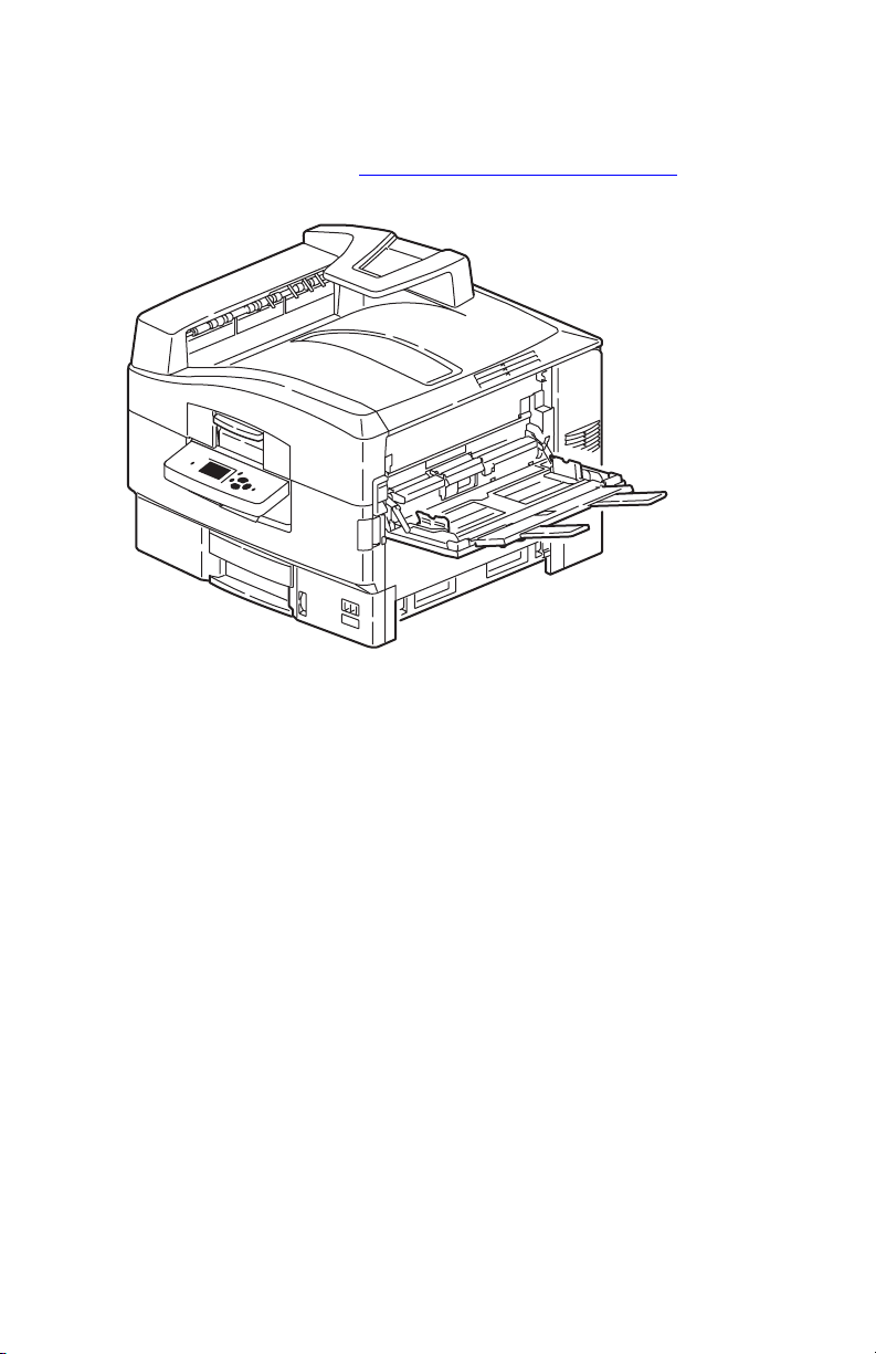
Printer Introduction and Overview
The Xerox Phaser 7400 Color Printer Service Manual is the primary document used
to repair, maintain, and troubleshoot this printer. For manual updates, Service
Bulletins, knowledge base, etc., see
technical support, contact your assigned Xerox Technical Support for this product.
www.xerox.com/office/7400support. For further
s7400-301
The Xerox Phaser 7400 Color Printer is a single pass, electrophotographic design,
using light emitting diodes (LED) for image exposure. The Phaser 7400 supports
PostScript 3 and PCL5c page description languages. Print performance for A4 paper
is 40 pages per minute (ppm) monochrome, 36 ppm for full color in 1-sided or
2-sided modes. Full color prints are produced via consecutively transferring the
subtractive primaries (cyan, magenta, yellow, and black) directly to paper.
Resolutions of up to 600 x 1200 dots per inch (dpi), 32-level grayscale print is
applicable at 600x600 dpi. The base configuration (Phaser 7400N) features USB 2.0
and 10/100baseT Ethernet Ports, 256 MB of memory, a 250-sheet multi-purpose
Tray
1 (MPT), a 550-sheet input tray (Tray 2), a 500-sheet facedown Top Output
Tray, and a 250-sheet faceup Side Output Tray.
Phaser 7400 printer options add memory, paper capacity and functionality. For
configurations not originally equipped, an internal Hard Drive is available for font
storage, storing print files, job collation, proof, personal, and secure print support. A
selection of RAM memory upgrades are available to raise the installed quantity to the
1 GB maximum. A 1650-Sheet High-Capacity Feeder (HCF) is available with three,
550-sheet universal trays. A 550-Sheet Feeder (Tray 3) Lower Tray Assembly (LTA)
is also available. On the output side, a 1000-Sheet Finisher provides punching,
stapling, saddle stitch, and offset stacking raising the output total to 1750 sheets. A
Duplex Unit is available to add automatic 2-sided printing for supported paper sizes
from all trays.
1-2 Phaser 7400 Color Printer Service Manual
Page 29

Printer Configurations
The Phaser 7400 Color Printer is available in five configurations. The main
differences are standard memory, optional high-capacity feeders, duplexing (2-sided
printing) capabilities, networking, and internal Hard Drive. The following table lists
the available configurations.
Printer Configuration
Features
7400N 7400DN 7400DT 7400DX 7400DXF
Max Print Speed (ppm)
color / monochrome
Hard Drive for Secure,
Proof, Personal, and
Saved Print Jobs
Standard Memory* 256 MB 256 MB 512 MB 512 MB 512 MB
USB Port Ye s Ye s Yes Ye s Ye s
10/100 Ethernet Port Ye s Ye s Yes Ye s Ye s
RAM Collation Ye s Ye s Ye s Ye s Ye s
Duplex Unit Optional Ye s Ye s Ye s Ye s
PostScript / PCL Fonts Yes Ye s Ye s Ye s Ye s
Banner Sizes Ye s Ye s Yes Ye s Ye s
Photo Modes Ye s Ye s Ye s Ye s Ye s
Resolutions (dpi):
Standard
Enhanced
Photo
Tray 1 (MPT)** Ye s Ye s Ye s Ye s Ye s
Optional Trays ** Optional Optional 1 x 550 3 x 550 4 x 550
550-Sheet Feeder** Optional Optional Ye s Optional Ye s
1650-Sheet Feeder** Optional Optional Optional Ye s Ye s
1000-Sheet Finisher*** Optional Optional Optional Optional Ye s
* All configurations have two memory slots supporting 256 MB and 512 MB cards, up
to a maximum of 1 GB.
** Trays 1 and 2 are standard on all configurations. All configurations support
additional paper trays in the following combinations:
One 550-Sheet Feeder (Tray 3)
One 1650-Sheet Feeder (Trays 3, 4, and 5 or 4,5, and 6)
One 550-Sheet Feeder (Tray 3) and one 1650-Sheet Feeder (Trays 4, 5, and 6)
*** Requires a Hard Drive and a total of 4 optional trays for fitment.
36/40 36/40 36/40 36/40 36/40
Optional Optional Yes Ye s Ye s
600x600x1
1200x600x1
600x600x5
600x600x1
1200x600x1
600x600x5
600x600x1
1200x600x1
600x600x5
600x600x1
1200x600x1
600x600x5
600x600x1
1200x600x1
600x600x5
General Information 1-3
Page 30

Metered Printing
Metered printing (PagePack), involves the combination of control software and
specialized Toner Cartridges to meter printer activity for billing purposes. The
Configuration page lists Metered Toner as Enabled when metering is enabled.
Metered Operation
When a metered printer is initialized at first power-up, the customer sets the printer to
Metered operation using a unique, factory-supplied, 4-digit PIN. Once set to Metered
operation, the control software performs the following:
1. The Mode and PIN-entered values in Engine Control Board NVRAM are set.
2. The Control Panel momentarily displays “Metered Toner is now enabled”, then
returns to “Ready” (if no other errors).
3. The First Time Tips pages and the Configuration page are printed.
If an incorrect PIN is entered, “Incorrect numeric password” displays with a prompt
“Retry” or “Do not retry.” Retry returns to the enter prompt, “Do not retry” returns to
the Replace [C][M][Y][K] Toner Cartridge error message. The error persists until the
correct PIN is entered.
Note
The Hidden Service menu provides an Enable Metered Toner option to restore
the Metered mode parameters to NVRAM should they become lost or corrupt.
Metered Toner Cartridges
To support metered printing, metered Toner Cartridges are available in all four colors.
When a metered Toner Cartridge is installed in a printer not set to Metered operation,
the printer displays the Replace [C][M][Y][K] Toner Cartridge error. If a metered
Toner Cartridge is placed into a printer manufactured before metering was available,
the printer displays Replace Incorrect Toner Cartridge. All other combinations of
normal or metered printer and cartridges are accepted without warning or error.
Diagnostics Mode
Service Diagnostics does not provide the utilities to set or clear Metered NVRAM
values. Service Diagnostics does not check these values and does not display the
current status of these values. However, the Configuration page does identify the
printer setting as mentioned above.
Note
When replacing the Engine Control Board from a metered printer, exchange
NVRAM devices or use the Save/Restore utilities in Service Diagnostics to
preserve the NVRAM settings. The Mode and PIN-entered values are not
affected by NVRAM reset utilities.
1-4 Phaser 7400 Color Printer Service Manual
Page 31

Parts of the Printer
Front View
1
6
7
8
2
3
4
5
1. Top Cover latch 6. Paper Catcher
2. Control Panel 7. Top Output Tray
3. Tray 2 8. Door A
4. Front Door 9. Tray 1 (MPT)
5. Level Indicator 10.Door B
9
10
7400-001
General Information 1-5
Page 32

Rear View
10
2
3
4
5
9
8
6
7
1
7400-002
1. AC Receptacle 6. USB Port
2. Door D 7. Ethernet Port
3. Door E 8. Serial Debug Port
4. Side Output Tray 9. Mode Select Port
5. Power Switch 10.Rear Cover
1-6 Phaser 7400 Color Printer Service Manual
Page 33

Control Panel
The Control Panel contains one tricolor LED, a display window, and six function
buttons. These buttons navigate the menu system shown on the display, perform
various functions, and select operational modes for the printer.
LED Indicators:
LED State Printer State
Green Ready to Print
Flashing Yellow Warning (but can still print)
Flashing Green In Power Saver mode or busy (receiving or processing data)
Flashing Red Error; cannot print
Control Panel Button Descriptions
Up Arrow Button
OK Button
Status Indicator LED
Cancel Button
Help (?) Button
Graphic Display
Back Button
Down Arrow Button
s7400-304
Control Panel Shortcuts
Action Press this at Power On
Skip Execution of POST Diagnostics OK
Print Service Diagnostics Menu Map Help (?)
Reset PostScript NVRAM Back + OK
Password Bypass Up Arrow + Down Arrow
Enter Service Diagnostics Back + Help (?)
General Information 1-7
Page 34

Image Processor Board
Transfer the following components, if installed, to the new board when replacing the
Image Processor Board.
Configuration Card
NVRAM
Hard Drive
Memory (RAM)
s7400-352
1-8 Phaser 7400 Color Printer Service Manual
Page 35

Printer Options
Phaser 7400 Color Printer options include:
■ 20 GB Hard Drive
■ Additional Memory
■ 550-Sheet Feeder (LTA)
■ 1650-Sheet Feeder (HCF)
■ Duplex Unit
■ 1,000-Sheet Finisher (with hole punch, staple, saddle-stitch, and offset)
Hard Drive
A 20 GB Hard Drive is available to enable the Job Collation, Saved Jobs, Proof,
Personal, and Secure Print options. The Hard Drive installs on the Image Processor
Board with stand-offs and connects to the board with a single data/power connector.
Hard Drive utilization appears on the Configuration page.
Additional Memory
The printer features two slots that accept 256 or 512 MB of high-speed DDR RAM.
All combinations are allowed for 256, 512, 768 MB, up to the maximum of 1 GB.
Memory modules must have the following characteristics:
■ DDR PC2700 Memory Standard
■ 200-Pin SODIMM
■ Unbuffered, Non-parity
■ Serial Presence Detect
■ 2.5 Volt
■ CL 2.5
s7400-004
The Startup and Configuration pages list the amount of RAM installed in the printer.
Installed memory not meeting the above specifications, is ignored by the printer.
General Information 1-9
Page 36

Configuration Card
A Configuration Card identifies the printer configuration, stores shadowed nonCRUM consumable data, consumable life counts, and network configuration
parameters.
550-Sheet Feeder
The 550-Sheet Feeder increases the input capacity of the printer. The Lower Tray
Assembly (LTA) attaches below Tray 2. When used in combination with the
1650-Sheet Feeder, the 550-Sheet Feeder is installed between the printer and 1650Sheet Feeder. Up to four optional 550-Sheet Feeders per printer, totaling six universal
trays (Trays 2~6), are allowed. However, when the 1650-Sheet Feeder High-Capacity
Feeder (HCF) is installed, only one additional 550-Sheet Feeder is allowed between
the HCF and printer. Electrical connection to the printer is made by a single interface
connector.
s7400-001
1650-Sheet Feeder
The 1650-Sheet Feeder adds three 550-sheet trays. Control signals reach the sheet
feeder by a single connection.
s7400-003
1-10 Phaser 7400 Color Printer Service Manual
Page 37

Duplex Unit
The Duplex Unit adds two-sided printing. The Duplex Unit is inserted into the
printer’s left side just below the Side Output Tray. Electrical connection is made by an
interface connector located inside the Duplex Unit cavity.
s7400-305
Finisher
The Finisher increases the output capacity of the printer by 1,000 sheets. Printer
output is directed to the Finisher by way of the side exit. Depending on the job
specifications, as paper enters the Finisher it can be punched, stapled, offset and
stacked depending on customer driver selections or Control Panel settings. The
Finisher’s Inverter is used to flip the media over. Control signals reach the Finisher
through a single connector.
Finisher
Inverter
s7400-306
General Information 1-11
Page 38

Maintenance Items
A maintenance item is a printer part or assembly that has a limited life, and requires
periodic replacement.
Fuser
Imaging Unit
Transfer Belt
Waste Toner Reservoir
Consumables
Consumables consist of the four toner cartridges used in the printer.
Toner Cartridge
s7400-307
s7400-308
1-12 Phaser 7400 Color Printer Service Manual
Page 39

Specifications
Memory Specifications
Characteristic Specification
Minimum RAM 256 MB
Maximum RAM 1 GB
Supported RAM SODIMM 200-pin module of 256 or 512 MB. All combinations are allowed
NVRAM Single chip of either PPROM or StrataFlash 16 MB
Consumable Life Specifications
Internal counters track Consumables and Maintenance Items life usage. The Image
Processor Board monitors these counters in order to display the near end-of-life and
end-of-use messages.
Life ratings are based on A-size sheets at 5% coverage. Imaging Unit life ratings are
based on average 3 page job length.
Toner Cartridges Print Life
for configurations of 256, 512, 768 MB, and 1 GB.
Black-Capacity
Color Capacity
Metered (PagePack) Capacity (all colors)
Maintenance Items
Imaging Unit 30,000
Fuser 100,000
Transfer Unit 100,000
Feed Roller Kit 100,000
Waste Toner Reservoir up to 30,000
15,000
7,500 or 15,000
15,000
General Information 1-13
Page 40

Electrical Specifications
Characteristic Specification
Primary line
voltages
Primary line
voltage
frequency range
Power
consumption at
rated voltage
input
110-127 V Printer - (90 - 135 V) 13 amp circuit
220-240 V Printer - (198 - 254 V) 7-8 amp circuit
100-120 V Printer - 50/60 Hz + 2 Hz
220-240 V Printer - 50/60 Hz + 2 Hz
Mode
Print Mode
Ready Mode
Sleep Mode
Condition
Maximum
Fuser On
Fuser Off
NOTE: Power the printer directly
100/120 VAC
1500 W or less
750 W or less
55 W or less
Physical Dimensions and Clearances
Print Engine Value
Height:
Width: 64.0 cm (25.2 in.)
Depth:
Weight: 84 kg (185 lb.)
1650-Sheet Feeder Value
Height: 40.1 cm (15.8 in.)
Width: 59.7 cm (23.5 in.)
Depth: 59.9 cm (23.6 in.)
Weight: 53 kg (117 lb.)
550-Sheet Feeder Value
Height: 10.9 cm (4.3 in.)
Width: 59.7 cm (23.5 in.)
Depth: 59.9 cm (23.6 in.)
Weight: 16 kg (36 lb.)
Finisher Value
Height: 101.6 cm (40.0 in.)
Width: 81.3 cm (32.0 in.)
Depth: 59.5 cm (23.6 in.)
Weight: 55 kg (122 lb.)
Surface Value
Tilt tolerance: Within 50 mm side to side.
47.1 cm (18.5 in.)
62.3 cm (24.5 in.)
from the wall outlet. Do not
use “Power Strips” as they
may limit available current.
220/240 VAC
1500 W or less
750 W or less
55 W or less
1-14 Phaser 7400 Color Printer Service Manual
Page 41

Minimum Clearances
61.0 cm (24 in.)
50.8 cm
(20 in.)
167.4 cm
(66 in.)
68.5 cm
(27 in.)
50.8 cm
(20 in.)
50.8 cm
(20 in.)
50.8 cm
(20 in.)
15.2 cm (6 in.)
127.5 cm (50 in.)
61.0 cm (24 in.)
15.2 cm (6 in.)
266.4 cm
(104.9 in.)
50.8 cm
(20 in.)
127.5 cm (50 in.)
s7400-309
General Information 1-15
Page 42

Functional Specifications
Functional Specifications
Characteristic Specification
Printing Process Imaging System: 4-tandem drums, electro-photographic system.
Exposure System: Light-emitting Diode (LED), 4 beams.
Development System: Dry type 2-component developer.
Fusing System: Heat fusing, free nip-belt system.
Color Medium Yellow, Magenta, Cyan, and Black Toner Cartridges
Resolution /
Addressability
Operating Modes Print Mode: Print Engine capable of making prints immediately.
Maximum Color
Coverage
Warm-up Time < 85 seconds from cold start (power off condition)
Standard
Enhanced
Photo
Ready Mode: 10 seconds from completion of a print.
Sleep / Power Saver Mode: Entered after a specified period of Print Engine
inactivity since completion of the last print.
All configurations are 240%
< 75 seconds from (Wake-up)
600 x 600 dpi (default)
1200 x 600 dpi
600 x 600 (5-bit) dpi
First Print Output Time
First Print Output Time (FPOT) is defined as a time from receipt of the print
command in Ready mode until the first page sourced from either Tray 1 or Tray 2 is
delivered to the Output Tray. Sourcing media from the optional trays increases FPOT.
Note
This does not include the execution times for the Boot Loader or POST which
vary depending on printer configuration.
Print Mode
Tray 1 (M P T) Tray 2 Tra y 3 Tray 4 Tr ay 5 Tr a y 6
Monochrome 12.0 13.5 14 15 16
Color 13 15.5 16.5 17.5 18.5
First Print Out Time* (maximum seconds)
*These conditions apply to the values in the table above:
Printer at Ready
A4 LEF paper
Plain paper mode
1-16 Phaser 7400 Color Printer Service Manual
Page 43

Image Specifications
Characteristic Specification
Maximum Print Area
Guaranteed Print Area
Skew < 1.0 mm across 220 mm image, < 1.5 mm from option trays
Registration
Leading Edge
Side Edge
Duplex (front to back)
Parallelism ± 0.5 mm across 220 mm image
Linearity
Ver tic al
Horizontal
Slant
Minimum margins = 5 mm (0.2 in.) on all sides
Maximum paper size = 328 mm x 1200 mm (12.9 in.x 47.25 in.)
Minimum paper size = 105 mm x 148 mm (4.13 in. x 5.83 in.)
The printer prints images meeting the Print Quality Specification
except the margin area, which is 5.0 mm inside each edge of
the paper.
± 1.0 mm
± 1.0 mm
±1.5 mm (A size), 2.2 mm (B size)
± 0.5 mm across 234 mm image
± 0.5 mm across 190 mm image
± 1.2 mm across 269 mm image
Environmental Specifications
Characteristic Specification
Temperature
Operating
Storage
Transport
Humidity (RH)
Operating
Storage
Transport
Altitude
Operating
Non-operating
Acoustic Noise (db)
Standby
Power Saver
Printing
10 to 32oC (50 to 89.6 oF)
0 to 43oC (32 to 109.4 oF)
-10 to 43oC (-14 to 109.4 oF)
Relative Humidity (50 - 70% to assure the best print-quality)
20 - 80%
10 - 90%
10 - 90%
0 to 2500 meters (8,000 ft.) at 25oC
0 to 6000 meters (20,000 ft.)
45.0db or less
43.0db or less
55.0db or less
General Information 1-17
Page 44

Media and Tray Specifications
The following table lists the paper sizes and weights supported in the printer trays.
Media and Tray Specifications
Specification Trays
Supported
Media Sizes
Supported
Envelopes*
Special
Media
Tr ay
Capacity
Paper Type
Letter
Legal
Executive
Statement
US Folio
A4
A5
A6
B5 JIS
ISO B5
Custom Size & Banner
Envelopes Weight
Commercial #10
Monarch Envelope
A7 Envelope Custom
DL Envelope
C5 Envelope
C6 Envelope
B5 Envelope
Custom
NOTE: Do not use envelopes with hot melt glue, windows, or
metal clasps.
Phaser 35-Series
Premium Transparencies
Letter
A4
(Other sizes through Tray 1
using custom size option.)
Phaser Premium
Postcards
Standard Paper
Transparency
Envelopes
Letter
A4
Size
8.5 x 11 in.
8.5 x 14 in.
7.25 x 10.5 in.
5.5 x 8.5 in.
8.5 x 13 in.
210 x 297 mm
148 x 210 mm
105 x 148 mm
182 x 257 mm
176 x 250 mm
8.5 x 35.4 in.
20 - 24 lb. Bond
4.12 x 9.5 in.
3.87 x 7.5 in.
5.25 x 7.25 in
110 x 220 mm
162 x 229 mm
114 x 162 mm
175 x 250 mm
216 x 279 mm (8.5 x 11 in.)
210 x 297 mm (8.27 x 11.69 in.)
216 x 279 mm (8.5 x 11 in.)
210 x 297 mm (8.27 x 11.69 in.)
Universal Tray
550 Sheets
100 Sheets
N/A
All Trays
All Trays
All Trays
All trays
All Trays
All Trays
All Trays
Tray 1 Only
All Trays
Tray 1 Only
Tray 1 + 2
Tray 1 Only
Tray 1 + 2
Tray 1 + 2
Tray 1 Only
Tray 1 Only
Tray 1 ( M P T )
100 Sheets
50 Sheets
10 each
1-18 Phaser 7400 Color Printer Service Manual
Page 45

Media and Tray Specifications
Specification Trays
Supported
Media Types
and Weights
Typ e
Plain Paper
Heavy Plain Paper
Thin Card Stock
Thick Card Stock
Labels
Letterhead
Glossy Paper
Digital Photo Paper
Phaser Premium Post-
cards
Pre-printed
Pre-punched
Special
Weight
65 - 90 g/m2 (17 - 24 lb. Bond)
85 - 120 g/m2 (22 - 32 lb. Bond)
100 - 163 g/m2 (30 - 60 lb. Cover)
160 - 216 g/m2 (59 - 80 lb. Cover)
N/A
85 - 120 g/m2 (22 - 32 lb. Bond)
100 - 163 g/m2 (81 - 110 lb. Text)
163 g/m2 (60 lb. Cover)
176 g/m2 (65 lb. Cover)
65 - 90 g/m2 (17 - 24 lb. Bond)
65 - 90 g/m2(17 - 24 lb. Bond)
100 - 163 g/m2 (30 - 60 lb. Cover
All Trays
All Trays
All Trays
All Trays
Tray 1 Only
All Trays
Tray 1 Only
Tray 1 Only
Tray 1 Only
All Trays
All Trays
All Trays
*Some wrinkling and embossing may occur when printing envelopes.
Note
For duplex configured printers, auto-duplex operation is available through all
trays. Refer to the Paper Tips page for information on which paper types can be
used for 2-sided printing.
For more details about supported paper and other media, print the Paper Tips page:
1. On the Control Panel, select Information, and then press the OK button.
2. Select Information Pages, and then press the OK button.
3. Select Paper Tips, and then press the OK button to print.
General Information 1-19
Page 46

Theory of
Operation
In this chapter...
■ Overview
■ Printer Controls
■ Paper Path of the Printer
■ Major Assemblies and Functions
Section
2
Page 47

Phaser 7400 Operational Overview
The Phaser 7400 Color Printer is a full-color LED printer using electrophotographic
recording principals to place a full color image onto the print media. The system, as it
appears in the following illustration, contains four Imaging Units comprised of a
drum and developing unit for each color Cyan, Magenta, Yellow and Black (CMYK),
and uses a Transfer Unit to transfer the toner image of each color onto print media
producing full-color prints.
The figure below illustrates the relative position of components involved in the
printing process.
Toner Cartridge
Fuser
Transfer Unit
LED Head
Imaging Unit
s7400-384
2-2 Phaser 7400 Color Printer Service Manual
Page 48

Imaging Unit
The function of each Imaging Unit component is listed in the following table.
Imaging Unit Components
Component Function
Drum The Drum is an aluminum cylinder coated with a layer of photo-
conductive material that retains electrical charges on its surface
until exposed to light.
Bias Charge Roller (BCR) The BCR uniformly distributes electrical charges over the drum
Developer Roller A thin layer of developer and toner adheres to the surface of this
Sponge Roller Transfers toner to the Developer Roller.
Agitation Bar The Agitation Bar stirs the developer mixture to achieve a
Cleaning Blade The Cleaning Blade removes toner remaining on the Drum.
Waste Toner Recovery Moves excess toner from the Imaging Unit to the Waste Toner
Toner Cartridge
Agitation Spring
surface, and erases the previous charge pattern.
roller, which transports the toner to the Drum surface.
uniform distribution of toner.
Recovery system for collection.
Shutter
Agitation Bar
Target
Charge Roller
Sponge Roller
Developer Roller
Drum
s7400-022
Theory of Operation 2-3
Page 49

LED Heads
The LED Heads receive signals from the Engine Control Board and scan the surface
of the four Imaging Unit drums to create a latent image. The resolution is either
600
dpi or 1200 dpi and is determined by the customer setting.
LED Head
Light Cover
LED Holders
s7400-385
Fuser
The Fuser, using a combination of heat and pressure, bonds the toner to the paper. The
Fuser is replaced as a unit. The Heat Roller is heated by two internal halogen lamps,
and the Pressure Roller is heated by a separate lamp. The Pressure Roller puts
pressure against Fuser Belt, media, and Heat Roller to melt the toner and bond the
image to the paper. After the toner image is fused to the paper, the paper passes
through the Fuser Exit Sensor indicating the sheet’s progress. To better understand
Fuser errors, Fuser components are described in the following table.
Fuser Components
Component Function
Heat Roller The Heat Roller is a metal tube with a coated surface and a
Heater Assembly inside. As paper passes between the Heat
Roller and Pressure Roller, the heat fuses the toner to the paper.
Pressure Roller The Pressure Roller is a metal shaft coated with sponge rubber.
Heater Lamps The Heater Lamps are quartz glass tubes containing heater
The Pressure Roller maintains pressure on the paper passing
between it and the Heat Roller. This pressure bonds the melted
toner to the paper.
coils. The Heater Lamps heat the Heat Roller.
2-4 Phaser 7400 Color Printer Service Manual
Page 50

Fuser Components (Continued)
Component Function
Temperature Sensors These are Thermistors having a known value of resistance that
Thermostats The Thermostats provide a second-level of protection. If the
Fuser Exit Sensor This sensor detects the arrival of the paper at the exit area of the
varies with temperature. The sensors monitor the surface
temperature of the Heat and Pressure Rollers.
Heat or Pressure Roller temperature exceeds the target
temperature, AC power is cut-off to the Heater Rods. Once the
Thermostats have opened, the Fuser must be replaced.
Fuser. When paper is present, the signal /EXIT is Low.
Fuser Life Expectancy
The life expectancy is 100,000 Letter/A4 size pages. Several factors reduce Fuser life:
■ Paper use larger than letter size
■ Printing on heavy media
■ Printing short-edge feed
■ Printing on transparencies or specialty media
■ Repetitive image, long print runs
Transfer Unit
The Transfer Unit transports the media under all four Imaging Unit drums using a
belt. Transfer Rollers within the Transfer Unit receive biasing voltages from the
HVPS to attract the toner from the drums to the media.
Imaging Unit Drums
KY MC
Transfer Unit Belt
Transfer Rollers
Transfer Unit Belt Motor
s7400-030
Theory of Operation 2-5
Page 51

Print Process Summary
The block diagram illustrates the steps involved in producing a full-color print. The
(numbers) indicate the corresponding description provided in the Print Process
Summary that follows this diagram.
Print Process Block Diagram
Drum C Drum M
Charged
with
(1)
electricity
Exposure
(2)
Develop-
(3)
ment
(5) Fusing
(8) Exit
Top Output Tray Side Output Tray
Charged
with
(1)
electricity
(2)
Exposure
Develop-
(3)
ment
(4) Transfer
Drum Y Drum K
Charged
with
(1)
electricity
(2)
Exposure
Develop-
(3)
ment
(6) Transfer Unit Cleaning
(7) Imaging Unit Cleaning
(9) Waste Toner Recovery
(1)
(2)
(3)
Charged
with
electricity
Exposure
Development
s7400-383
Refer to the Print Process Block Diagram above to relate each of the following
process steps to an individual component.
2-6 Phaser 7400 Color Printer Service Manual
Page 52

1. Charging: The charge roller (RTC) is negatively charged by the High-Voltage
Power Supply (HVPS) and is kept in contact with the drum surface to provide a
uniform negative charge on the drum as it rotates at a constant speed. This occurs
simultaneously for CMYK.
HVPS
Drum
Charge Roller
s7400-018
2. Exposure: The Light Emitting Diode (LED) Head emits light to the negatively
charged surface of the drum. Areas of the drum surface receiving the light
attenuate the negative charge based on light intensity and surface potentials,
forming the latent electrostatic image on the drum surface. This occurs
simultaneously for CMYK.
Charge
LED Head
LED Head
Roller
HVPS
Drum
Drum
Paper
s7400-017
3. Development: The Developer Roller applies toner to the latent image formed
on the surface of the drum. Toner transfer occurs as follows:.
■ The sponge roller transfers toner to the Developer Roller. The toner is
negatively charged.
■ The toner cleaning blade removes excess toner on the Developer Roller to
form a thin film of toner on the surface of the Developer Roller.
Theory of Operation 2-7
Page 53

■ The toner is attracted to the latent image on the surface of the drum at the
point where the drum is in contact with the developing roller.
Toner
Charge
Roller
Cleaning
Blade
Drum
Developer
Roller
Sponge
Roller
s7400-019
4. Transfer: The Transfer Roller, made of a conductive sponge, presses the paper
against the surface of the drum. This process sandwiches the paper between the
drum and the Transfer Unit belt. A positive charge, supplied by the HVPS
through contacts on the Transfer Unit, is applied to the Transfer Roller attracting
the negatively-charged toner from the surface of the drum onto the paper.
Drum
Paper
Transfer Unit
Belt
Transfer
Roller
HVPS
s7400-020
2-8 Phaser 7400 Color Printer Service Manual
Page 54

5. Fusing: The Fuser uses a combination of heat and pressure to bond the toner
image to the paper.
Thermostat
Thermistor
Paper
Heat Roller
Pressure Roller
Pat
Fuser Belt
Thermistor
Thermostat
s7400-021
6. Transfer Unit Cleaning: Toner remaining on the Transfer Unit belt is removed
by a cleaning blade and transported by Auger to the toner waste port.
Transfer Unit Belt
Direction of Belt Rotation
Cleaning Blade
Auger
Toner Waste Port
s7400-023
7. Imaging Unit Cleaning: Toner remaining on the drum, following image
transfer to the media, is scraped off by a cleaning blade and collected.
8. Paper Exit: The paper is then advanced either upward to the Top Exit or
downward towards the Side Exit depending on the Exit Gate position.
9. Waste Toner Recovery: Excess toner collected from the Imaging Unit drums
and the Transfer Unit belt is carried by an Auger Tube to the Waste Toner
Reservoir located behind the Front Door.
Theory of Operation 2-9
Page 55

Printer Controls
Print-Quality Modes
There are four print-quality modes:
Print-Quality Mode Description
Automatic Automatically selects the optimal print-quality mode for the paper
Standard 600 X 600 dpi resolution. High-speed, general-purpose mode for
Enhanced
Photo
type. For example, Photo print-quality mode is used when printing on
Glossy Paper and Standard print-quality mode is used when printing
on Plain Paper. (This setting is only available in the printer driver.)
crisp, bright, color prints. Recommended for most office use and quick
prints.
600 X 1200 dpi resolution. High-quality mode for fine lines and detail.
Recommended for vibrant, saturated, color prints. Balances printing
speed with quality.
600 X 600 dpi resolution. Highest-quality mode for color prints and
smoothest light colors. Recommended for photographs, smooth
shaded drawings, and color.
Color Registration Control
The printer uses a single-pass, quad system where each color (Yellow, Magenta,
Cyan, and Black) has its own imaging drum. Images are formed on the drums, in the
respective colors, and then layered on the media to form one image. To monitor color
registration, photo-reflective, Color Registration Sensors are mounted inside the
Registration Sensor Assembly. These sensors are positioned at the front and rear
edges of the Transfer Unit belt as shown in the following figure.
2-10 Phaser 7400 Color Printer Service Manual
Page 56

Imaging Unit
Drum
Transfer Unit
Belt
C
C
M
M
Y
Y
K
K
LED Head
Belt Running Direction
Color Registration Sensor
Cleaning Blade
Transfer Belt
Cleaning Blade
Color Registration Front Sensor
Belt Running Direction
Color Registration Rear Sensor
(Transfer Unit as seen from below)
s7400-041
The Color Registration Sensors are used to measure the amount of misalignment
based on the position of the color patches in relation to the black toner patch that
precedes them. According to this measurement, the printer determines the correct
value and automatically adjusts color registration in the main scanning, sub-scanning,
and diagonal directions.
Theory of Operation 2-11
Page 57

To avoid a positional shift between the different color images, the color registration
control generates an alignment pattern (a series of primary color toner patches on
either side of the Transfer Unit belt.
Color Registration Sensor Front
Color or Check Pattern
Color Registration Sensor Rear
s7400-623
Color registration control is outlined below:
1. With no toner on the Transfer Unit, the output value of the Color Registration
Sensors is measured to determine the reference value.
2. Patches for color registration control are generated on the edges of the Transfer
Unit belt.
3. A solenoid-activated Registration Shutter opens so the sensors are exposed to the
toner patches on the Transfer Unit belt.
4. The position of the patches generated is measured by the Color Registration
Sensors.
5. The amount of registration shift is calculated from the reference value
determined in Step 1, and the patch alignment measured in Step 4.
6. The image write timing is changed to compensate for any registration shift.
Color registration is checked when the power is turned On, a cover is closed, the
printer is idle for more than 2 hours, or after printing 400 sheets.
2-12 Phaser 7400 Color Printer Service Manual
Page 58

Automatic Density Control
The printer uses a series of test patches printed down the center of the Transfer Unit
belt to monitor the density of toner being supplied to the Imaging Unit drums. The
test patches consist of a grouping of all four colors applied repeatedly to the Transfer
Unit belt at density levels of 15, 30 50, 70, 85, and 100%. During the adjustment
cycle, these patches are printed twice and the ADC Sensor voltage outputs are stored
as reference values. During the status cycle, the test patches are generated once and
the resulting ADC Sensor voltages are compared to the reference values obtained
during the adjust cycle. Differences in the adjust and status ADC Sensor values
indicate how much to adjust the amount of toner being dispensed for each color.
The following diagram depicts the Transfer Unit belt with the test patches.
Transfer
Unit
x2 Times
Duty 100%
Duty 70%
Duty 30%
ADC Sensor
Transfer
Unit
ADC Sensor
Duty 100%
Duty 85%
Duty 70%
Duty 50%
Duty 30%
Duty 15%
s7400-624
Selective Control: Paper Pick
Unless changed in printer setup, the default tray is Tray 2. Trays in the optional
1650-Sheet Feeder are identified as Trays 3, 4, and 5. The tray in the optional
550-Sheet Feeder is identified as Tray 3. If both optional feeders are installed, the
550-Sheet Feeder tray is identified as Tray 3, and the trays of the 1650-Sheet Feeder
are identified as Trays 4, 5, and 6.
Note
The Phaser 7400 printer supports a maximum of 4 optional trays.
Theory of Operation 2-13
Page 59

Image Transfer Control
The printer monitors environmental conditions with the temperature and humidity
sensors. The printer computes the optimal transfer voltage under the current
environmental conditions (temperature and relative humidity), and applies the optimal
transfer voltage to the Imaging Units and Transfer Unit Rollers.
Fuser Temperature Control
During Fuser temperature control the printer’s target temperature is set based on the
media weight reported by the Media Thickness Sensor. The target temperature is also
changed according to the printer’s internal temperature and humidity detected with
the Temperature and Humidity Sensor, print count, print mode, media type, and input
power supply voltage. Different target temperatures are set for standby, printing, and
process control.The Heat Roller surface temperature is controlled to match the target
temperature by turning the heater rods On and Off.
Fuser temperature is regulated according to the sum of the temperatures detected at
the Heat Roller and Pressure Roller surfaces. There is also a thermostat for safety
purposes. When the Heat Roller temperature rises above a certain temperature, the
thermostat opens and shuts down the power supplied to the heater rods.
Consumable Control
The new/in-use condition of maintenance units is determined by the condition of a
fuse. If the fuse in either the Fuser, Imaging Unit, or Transfer Unit is intact, the unit is
recognized as a new. This fuse is checked when the printer is turned On, or a cover
has been opened. When a new unit is detected, the printer resets the unit’s life counter
and blows the fuse indicating the unit is in-use. The count will not indicate it has been
reset until two pages have been printed.
Consumable Life Counter Behavior
Internal counters track consumable life usage and store the values on the Engine
Control Board EEPROM. The Image Processor Board stores the pixel count
information in NVRAM and monitors these counters in order to display the
consumable near end-of-life and at end-of-life messages.
The toner states displayed are OK, Low, and Empty. When an empty state is reached,
the printer terminates printing at the end of the current page and displays the
appropriate message on the Control Panel. No further jobs are accepted. All printer
CRCs wait for the current print job to finish before declaring a Low or Empty state.
2-14 Phaser 7400 Color Printer Service Manual
Page 60

Sensors
The printer contains sensors of various types that perform a variety of functions. One
group of sensors track the progress of the paper along the paper path, and detect if a
paper jam occurs. Other sensors detect the presence of the Toner Cartridges, stop
printer activity if a door is open (interlock), detect the presence and size of media in
the trays, and monitor the fusing temperature.
Sensor Types
The types of sensors used vary with function. In general, there are four types in use:
Photo Sensors
Two types of photo sensors are used, photo-reflective and photo-receptive.
Photo-reflective sensors use light reflected back from an object to detect its presence.
Photo-receptive sensors use an actuator or the object itself to block the light path to
detect an object or condition.
Photo-reflective sensors have the light emitter and light receiver aligned on a single
surface. Output of the photo-receptor is High (> +4.5 V) when light is being reflected
back and Low (< +.3 V) when it isn’t. Photo-receptive sensors consist of a LED in one
arm of a U-shaped holder, and a photo-transistor in the other arm. When the sensing
area is unobstructed, light falls on the photo-receptor sending the signal High. If the
light is interrupted, the photo-transistor goes Low. The figure below shows a typical
photo-receptive sensor with the Hooks (catches) used to secure the sensor to its
bracket.
Hooks
Hook
Sensor Bracket
s7400-310
Theory of Operation 2-15
Page 61

Microswitches
Microswitches are used primarily as paper size sensors and cover or door interlocks.
They are in a normally open state, and close when actuated. A bank of microswitches
is used to detect paper size in the universal trays.
Thermistors
Thermistors have a known value of resistance at a certain temperature. Used primarily
in the Fuser for temperature sensing.
Hall-Effect
Hall-Effect sensors detect the magnetic properties of the actuator. Hall-Effect sensors
are used to monitor activity of the Waste Toner Recovery system and Transfer Unit
belt. Use a magnetic source to actuate these sensors during testing.
List of Sensor and Interlock Types
Name Type Function
Level Sensor Photo-receptive Detects paper stack height in Trays 2~6.
No Paper Photo-receptive Detects no paper condition in all trays.
Paper Size Microswitch array Detects the tray and the paper size.
Registration Photo-receptive Detects paper at the registration rollers.
Color Registration Photo-reflective Monitors color registration.
Feed-Out Photo-receptive Detects paper leaving the feeder.
Fuser Exit Photo-receptive Detects paper as it leaves the Fuser.
Stack Full Photo-receptive Detects when the output tray is full.
Temperature Thermistor Monitor Fuser roller temperatures.
Door Interlocks Microswitch Interrupts +24 V to the Motors.
Low Toner photo-reflective Detects toner in the Imaging Units.
Fuser Thermostats Thermostatic switches Interrupts AC power to the Fuser.
Offset Home Photo-receptive Detects Offset carriage position.
Temp/Humidity Integrated circuit Monitors the printer’s environment.
Waste Toner Hall-effect Monitors waste augers and transfer belt.
CRUM antenna RFID code reader Communicates with the CRUMs.
2-16 Phaser 7400 Color Printer Service Manual
Page 62

Sensors in the Printer
The following illustrations identifies the location of each sensor.
Color Registration Sensors
Waste Toner Reservoir
Auger Rotation Sensor
Waste Toner Reservoir Full Sensor
Transfer Unit Belt Rotation Sensor
Fuser Exit Sensor
Media Slack Sensor
Door E Detect Sensor
Toner Supply CM Sensor
Low Toner Sensors
Drum Phase Sensors
ADC Sensor
Temperature/Humidity Sensor
Toner Supply
YK Sensor
Imaging Unit
Up/Down
Sensor
Waste Toner
Auger Rotation
Sensor
s7400-586
Door A Interlock Switch
Fuser Release
Sensor
CRUM Antennae
Top Cover
Interlock Switch
Waste Toner Reservoir
Detect Switch
MPT Home Position Sensor
Door B Detect Sensor
Media Thickness Sensor
-
Theory of Operation 2-17
Page 63

The diagram below identifies the paper feed sensors.
8
Job Offset
Trailing Edge Sensor
Side Output Tray
Stack Full Sensor
Job Offset Home Position Sensor
Paper Size Switch
Top Output Tray Stack Full Sensor
Side Output Tray
Detect Sensor
Feed Out #1
Sensor
Transfer Unit
Entrance
Sensor
Registration
Sensor #1
MPT Level
Sensor
OHP Sensor
Feed Out
Sensor #2
MPT No Paper
Sensor
Tray 2 Level Sensor
No Paper Sensor #2
Registration Sensor #2
Tray 2 Low Paper Sensor
s7400-58
2-18 Phaser 7400 Color Printer Service Manual
Page 64

Sensor Functions
The following table lists the function of each sensor.
Sensor Functions
Sensor Function Sensor State
Top Output Tray
Stack Full Sensor
Side Output Tray
Stack Full Sensor
Side Output Tray
Detect Sensor
Job Offset Home
Position Sensor
Job Offset Trailing
Edge Sensor
Top Cover Interlock Detects the position of the Top Cover. On: open
Door A Interlock Detects the position of Door A. On: open
Door B Detect Detects the position of Door B. On: open
Door C Detect Detects the position of Door C for Trays 3 ~ 6. On: open
Door D Detect Detects the position of Door D. On: open
Door E Detect Detects the position of Door E. On: open
Waste Toner
Reservoir Detect
Switch
Fuser Exit Sensor Detects media at the Fuser Exit. On: media present
Fuser Temperature Monitors the Fuser process temperature. Reference voltage
Media Slack Sensor Detects media slack at the Fuser entrance. On: slack
Media Thickness
Sensor
Temperature/
Humidity Sensor
Tray 1 (MPT) FeedOut Sensor #1
Tray 1 ( M PT ) N o
Paper Sensor
Tray 1 (MPT) Level
Sensor
Detects the Top Output Tray stack height. On: not full
Off: full
Detects the Side Output Tray stack height. On: not full
Off: full
Detects whether the Side Output Tray is open or
closed.
Detects the position of the Job Offset carriage. On: not home
Detects the trailing edge of the media for the Offset
carriage.
Detects the presence of the Waste Toner Reservoir. On: present
Adjusts print parameters according to media
thickness.
Measures environmental conditions to calculate the
optimal transfer voltage.
Detects media leaving the Feed Rollers. On: media present
Detects the absence of media in the tray. On: media present
Detects the Tray 1 (MPT) media supply. On: media present
On: open
Off: closed
Off: home
On: media present
Off: media absent
Off: closed
Off: closed
Off: closed
Off: closed
Off: closed
Off: closed
Off: absent
Off: media absent
Off: no slack
Reference voltage
Reference voltage
Off: media absent
Off: media absent
Off: media absent
Theory of Operation 2-19
Page 65

Sensor Functions (Continued)
Sensor Function Sensor State
Tray 1 (MPT) Home
Position Sensor
Transfer Unit Belt
Rotation Sensor
Color Registration
Sensors
Fuser Release
Sensor
Waste Toner Auger
Rotation
Waste Toner
Reservoir Auger
Rotation
Waste Toner
Reservoir Full
Transfer Unit
Entrance Sensor
Registration Sensor #1Detects media at Registration Roller #1. On: media present
Duplex Entrance
Sensor
Duplex Reverse
Sensor
Duplex Front Sensor Detects the trailing edge and exit from the Duplex
Duplex Rear Sensor Detects the leading edge following inversion. On: media present
Toner Cartridge
CRUMs
Low Toner Sensors Detects full, low, and empty state of Toner
Imaging Unit Drum
Phase Sensors
Lift Uplink Sensor Detects the position of the Lift Uplink On: IUs up
OHP Sensor Detects the presence of transparency media. On: opaque
Paper Size Switches Detects the size of media loaded in the universal
Feeder
Registration Sensor
Feeder
Level Sensor
Detects the position of the Tray 1 (MPT) Turn Clutch
for pick operations.
Used to count Transfer Unit belt revolutions. Voltage pulse
Monitors color registration pattern produced during
automatic color registration processing.
Detects the presence of the Fuser. On: absent
Detects Waste Toner Manifold Auger rotation. Voltage pulse
Detects Waste Toner Reservoir Auger rotation.
Provides count signal for cartridge life.
Detects when the Waste Toner Reservoir is full. On: full
Detects media leaving Registration Roller #1. On: media present
Detects media entering the Duplex Unit. On: media present
Detects the trailing edge and signals the Duplex
Gate Solenoid to switch position.
Unit.
Detects the type of Toner Cartridge installed. Data
Cartridges.
Detect the position of the Imaging Unit drums. On: absent
trays.
Detects media at the universal tray’s Registration
Roller.
Detects the lift position of media in the universal
trays.
On: not home
Off: home
Reference voltage
Off: present
Voltage pulse
Off: not full
Off: media absent
Off: media absent
Off: media absent
On: media present
Off: media absent
On: media present
Off: media absent
Off: media absent
Sensor state
transition timing
Off: present
Off: IUs down
Off: transparent
See chart.
On: media present
Off: media absent
On: media present
Off: media absent
2-20 Phaser 7400 Color Printer Service Manual
Page 66

Sensor Functions (Continued)
Sensor Function Sensor State
Feeder
Feed-Out Sensor
Feeder
No Paper Sensor
Feeder
Low Paper Sensor
Detects media leaving the universal tray’s Feed
Rollers.
Detects the absence of media in the universal trays. On: media present
Detects a low condition of media loaded in the
universal trays.
On: media present
Off: media absent
Off: media absent
On: media present
Off: media absent
Paper Level Detection
As paper is fed from the tray, the paper level drops. When the paper level reaches a
certain point, an actuator unblocks the Level Sensor signaling the control logic to stop
paper feed and raise the tray bottom. Raising the tray bottom pushes the paper up to
achieve optimum force against the Feed Roller and blocks the Level Sensor resuming
paper feed. This loop continues until the No Paper sensor is activated. Paper level
sensing operates the same way for Trays 2 through 6. Tray 1 (MPT) uses No Paper
sensing only.
Paper Present Detection
When the last sheet is fed from any of the trays, the No Paper Sensor actuator drops
into an opening in the paper tray, unblocking the sensor. Feeding is inhibited until
paper is loaded into the tray.
Transparent Media Detection
An Over Head Projector (OHP) Sensor is mounted on Door A at the Registration
Assembly entrance. This sensor monitors media entering the Registration Assembly
and signals when transparent media is being fed.
Automatic Media Thickness Detection
The printer uses the Media Thickness Sensor to determine the thickness of media
passing through the Registration Assembly. The printer automatically adjusts the
Fuser temperature, Fuser speed, and electrophotographic parameters to accommodate
the detected media weight. Automatic thickness detection (ATS) is available from any
media source.
Note
A special paper type is available in the Tray Paper Type menu that turns off
ATS when selected. This allows manual configuration of print parameters if the
automatic settings do not produce the desired result.
Theory of Operation 2-21
Page 67

Paper Size Detection
Trays 2 through 6 automatically sense the standard size media loaded in the printer by
using the Paper Size Switches mounted on the frame at the back of the tray opening.
When paper is loaded in the tray and the paper guides are adjusted, the levers on the
bottom of the trays change the Paper Size Switch Actuators.
Actuating different combinations of the Paper Size Switches produces different
combinations of high and low signals. These signals identify what size of paper has
been loaded and what to display on the Control Panel. Also, any actuation of the size
switches signals the Engine Control Board that the tray is present and closed.
Universal Tray Paper Size Switch States
SW1 SW2 SW3 SW4 Media Size
0 0 0 0 No tray installed
1 1 1 1 A/Letter (LEF)
1 0 1 0 A/Letter (SEF)
1 0 0 1 A3
0 0 1 1 A3-Nobi
1 1 1 0 A4 (portrait)
0 0 1 0 A4 (landscape)
0 1 1 0 A5
0 1 1 1 A6
0 0 0 1 B4
1 1 0 0 B5 (LEF)
1 0 0 0 B5 (SEF)
1 0 1 1 B/Tabloid
1 1 0 1 Executive
0 1 0 0 Ledger 13 in.
0 1 0 1 Legal 14 in.
s7400-645
2-22 Phaser 7400 Color Printer Service Manual
Page 68
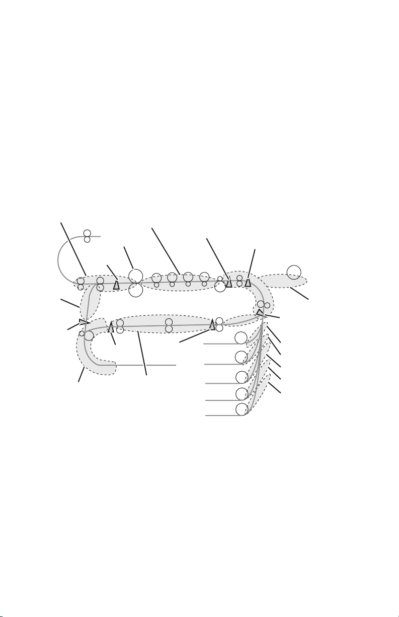
Jam Detection
The printer checks for a paper jam when the printer is powered on and during
printing. When a paper jam occurs, printing immediately stops. Below is a diagram of
jam locations within the printer.
■ Media Jams occur in the paper path if the associated sensor does not turn On
within a specified amount of time, meaning the jam occurs prior to reaching the
sensor, or if the sensor does not turn Off within a specified amount of time,
meaning the jam occurs along the path of the sensor.
■ Misfeeds occur when the paper can not be loaded from the tray.
■ Paper size errors occur when the Registration Sensor does not turn Off within a
specified amount of time based on paper size settings in NVRAM.
Jam at Door E
Exit Sensor
Jam at
Door D
Duplex
Entrance
Sensor
Jam at Duplex Entrance
Jam at Fuser
Double Rear
Sensor
Jam under
Imaging Units
Double
Front Sensor
Jam in Duplex
Transfer Unit
Entrance Sensor
Tray 2
Tray 3
Tray 4
Tray 5
Tray 6
Registration #1 Sensor
Jam at Door A
Feed-out Sensor #1
Jam at Door B
Jam at Door C
Jam at Door C
Jam at Door C
Jam at Door C
s7400-036
Theory of Operation 2-23
Page 69

Interlock Detection
If the Top Cover, Door A is opened, or the Waste Toner Reservoir is removed, an
Interlock Switch is opened cutting the +24V source to the HVPS. At the same time,
the CPU receives a signal indicating the Interlock Switch state, and displays the
appropriate error message.
Toner Detection
Each Imaging Unit contains an Agitation Gear and Agitation Bar. The Agitation Bar
moves toner delivered by the Toner Cartridge to the area above the Developer Roller.
Located at one end of the Agitation Bar is the Low Toner Sensor target.
The photo-reflective, Low Toner Sensor mounted on the Imaging Unit Sensor Board
detects the target at the end of the Agitation Bar and changes state in relation to light
reflected back from the target. As the toner level drops, the period of time the
Agitation Bar target remains at its highest point is reduced. This change in Agitation
Bar timing signals toner level changes.
OFF Time (Minimum Height) ON Time (Maximum Height)
Low Toner
Sensor
Agitation Bar
Target Board
s7400-173
2-24 Phaser 7400 Color Printer Service Manual
Page 70
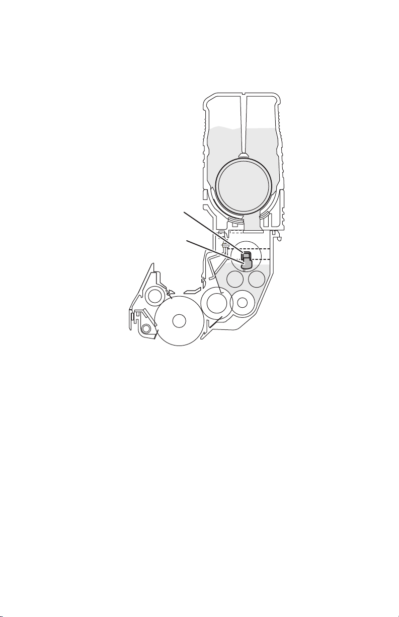
Toner Full State
When the Imaging Unit is at a toner full state, the Agitation Bar target remains at its
maximum height for a period exceeding .85 seconds. Periods in excess of .85 seconds
indicate a toner full state. Periods below .85 seconds indicate at toner low state.
Agitation Bar
Target
Toner Full: 100g
Toner Low: 75g
s7400-039
Toner Low State
As the toner supply is depleted at the Imaging Unit Drum, the period of time the
Agitation Bar remains at its lowest position increases reducing the amount of time the
target remains in the sensor’s range. This period of time (<.85 sec.) is monitored to
determine when a toner low condition exists.
Note
The time used to determine the amount of toner in the Imaging Unit varies with
print speed. The value of .85 seconds relates to a print speed of 37 ppm.
Theory of Operation 2-25
Page 71

Toner Cartridge
Agitation Spring
Shutter
Agitation Bar
Target
Toner Full: 100g
Toner Low: 75g
s7400-040
Toner Supply
If after checking the Low Toner Sensor three times, the state remains low, then the
toner supply agitator and toner cartridge agitation spring rotate, supplying additional
toner to the Imaging Unit. This continues until one cycle of toner high level is
detected. At this point, the toner supply agitator and a toner cartridge agitation spring
stop.
When a toner low state is detected 20 consecutive times, it indicates that the Toner
Cartridge is low. Once this condition is recognized, the Toner Low warning message
for the appropriate color is displayed after the printing of an equivalent of 5%
coverage for 200 A sized sheets. At this point, the Toner Cartridge is considered
empty.
2-26 Phaser 7400 Color Printer Service Manual
Page 72

Input Paper Path
Paper is transported through the printer along the paper path shown below.
Exit Rollers
Duplex
Entrance
Duplex
Transport
Rollers
Roller
Fuser
Tray 2
Tray 3
Tray 4
Tray 5
Tray 6
Registration
Roller #1
Tray 1 (MPT)
Feed Roller
Registration
Roller #2
Transfer
Unit Belt
Feed Roller
s7400-024
Paper Fed from Tray 1 (MPT)
1. Paper loaded in the tray is detected by the Tray 1 (MPT) No Paper Sensor.
2. The Registration Motor rotates CCW (b) lifting the sheet to the pre-feed position
detected by the Tray 1 (MPT) Level Sensor.
3. The Feed Motor is shared with Tray 2. To feed media from Tray 1 (MPT), the
Feed Motor reverses direction (CCW) to drive the Pick and Feed Rollers pulling
the sheet into the printer
Theory of Operation 2-27
Page 73

4. The leading edge of the sheet is detected by the Feed-Out Sensor #1. Depending
on the size of the sheet, the Feed Motor continues to drive the sheet until the
leading edge reaches the Registration Sensor #1 and a deskew buckle is induced
to align the sheet.
5. The Registration Motor rotates CW (a) and the Registration Clutch #1 is engaged
moving the media to the Transfer Unit Entrance Sensor. The Feed Motor
continues to rotate until the leading edge arrives at the Transfer Unit Entrance
Sensor.
6. As each sheet passes the Feed-Out Sensor #1, the Registration Motor lifts the
next sheet to pre-feed position.
7. Following the last sheet being fed, the Level Sensor goes low, the Registration
Motor rotates in the CCW (b) direction to return the Lift Plate to a home position
detected by the Tray 1 (MPT) Home Position Sensor.
Registration Sensor #1
Transfer Unit
Entrance Sensor
Registration
Roller #1
Registration Clutch #1
Feed-Out Sensor #1
Retard Roller
a
Feed Roller
Pick Roller
Level Sensor
Paper
No Paper Sensor
Transport Roller
b
Registration Motor
Feed Motor
s7400-171
2-28 Phaser 7400 Color Printer Service Manual
Page 74

The Tray 1 (MPT) Lift Plate should remain down (home position) when opened. It
should only lift when media is sensed. However, the Tray 1 (MPT) Lift Plate is spring
loaded. These springs are compressed under the Lift Plate by the Lift Arms driven by
the Registration Motor.
When you open Door A, the Lift Arm gear train is disengaged from the Registration
Motor and the springs are free to raise the Lift Plate. This becomes important when
servicing Tray 1 (MPT) as the Lift Arms can be trapped underneath the Lift Plate.
When the printer's on, closing the Tray 1 (MPT) and then reopening it returns the Lift
Plate to home position. When the printer's off, to return the Lift Plate to home
position, close the Tray 1 (MPT) and Door A. Next, open Door A with the Tray 1
(MPT) closed. Now, when Tray 1 (MPT) is opened, it should be back to its home
position.
Components of Tray 1 (MPT) include:
■ No Paper Sensor
Detects presence or absence of print media in the tray.
■ Home Position Sensor
Detects the position of the lift arm. When the lift arm is down, the lift plate is at
Home Position.
■ Level Sensor
Detects the leading edge of the media based on the position of the Actuator.
■ Registration Clutch #1
This clutch transfers Registration Motor drive to the lift arms.
■ Feed-Out Sensor #1
Detects the leading edge as the media leaves the Feed Rollers.
■ Registration Roller #1
This roller assembly aligns the leading edge of the sheet to correct any skew.
■ Registration Sensor #1
These sensors detect the presence of media as it arrives at the Registration
Rollers.
■ Transfer Unit Entrance Sensor
Detects the media as it leaves the Registration Roller #1.
Theory of Operation 2-29
Page 75

Paper Fed from Tray 2
1. Paper loaded in the tray is detected by the Tray 2 Paper Size Switch.
2. The Tray 2 Lift Motor rotates lifting the sheet to the pre-feed position detected by
the Tray 2 Level Sensor.
3. The Feed Motor turns (CCW) driving the Feed and Pick rollers to feed the sheet
from Tray 2.
4. The Feed-Out Sensor #2 detects the media as it leaves the Feed Rollers.
5. The Feed Motor continues to rotate until a deskew buckle is induced in the sheet
against the Registration Roller #2. Registration Sensor #2 goes High when the
sheet reaches the Registration Roller #2.
6. The sheet moves towards the Transfer Unit when the Registration Clutch #2 is
engaged driving the Registration Roller #2 and Transport Rollers.
7. As the sheet reaches the Registration Roller #1, it is detected by the Registration
Sensor #1.
8. When the Registration Sensor #1 goes High, the Registration Clutch #1 is
activated to move the sheet through the Registration Roller #1 to the Transfer
Unit.
9. The sheet is detected by the Transfer Unit Entrance Sensor and the Transfer Unit
Motor rotates to drive the sheet through the Imaging Units.
10. As the trailing edge of each sheet passes the Feed-Out Sensor, the Lift Motor lifts
the next sheet to pre-feed position.
2-30 Phaser 7400 Color Printer Service Manual
Page 76

Registration Roller #1
Transfer Unit
Entrance Sensor
Registration Sensor #1
Pick Roller
Registration
Clutch #1
Feed Roller
Registration
Clutch #2
Feed-Out
Sensor #2
Transport Rollers
Registration
Roller #2
Registration
Sensor #2
Paper
Feed Motor
Retard Roller
Registration Motor
s7400-026
Theory of Operation 2-31
Page 77

■ No Paper Sensor
Detects presence or absence of print media in the tray based on the position of the
Actuator.
■ Level Sensor
Detects presence of media in the tray based on the position of the Actuator.
■ Paper Size Switches
Detects media size using the position of the side and rear guides, and presence of
the paper tray.
■ Registration Motor
This motor drives the Registration Rollers to pull media from the tray into the
paper path.
■ Registration Clutch #2
This clutch transfers Tray 2 Registration Motor drive to the Registration Rollers.
■ Registration Roller #2
This roller is used to align the leading edge of the sheet to correct any skew.
■ Registration Sensor #2
This sensor detects the media as it arrives at the Registration Roller #2.
■ Feed-Out Sensor #2
This sensor detects the media as it leaves the Tray 2 Feed Rollers.
■ Feed Motor
This motor drives the Feed Rollers to pick paper from the tray and position it at
the Registration Roller.
■ Lift Motor
This motor lifts the tray’s base plate raising the media to the pre-feed position.
■ Low Paper Sensor
The actuator lowers as print media is used in the tray. When the actuator lowers
to a pre-determined position, it blocks the sensor to trigger a low paper status.
2-32 Phaser 7400 Color Printer Service Manual
Page 78

Paper Fed from Optional Trays
The following describes the paper path as it is fed from the optional Tray 3. Trays 4
through 6 function in the same manner. Media moves along the paper path as follows:
1. Paper loaded in the tray is detected by the Paper Size Switches.
2. The tray’s Lift Motor rotates lifting the sheet to the pre-feed position detected by
the Level Sensor.
3. The Feed Motor turns (CCW) driving the Feed and Pick rollers to feed the sheet
from the tray into the Registration Roller.
4. The Feed-Out Sensor #3 detects the media as it leaves the Feed Rollers.
5. As the trailing edge of each sheet passes the Feed-Out Sensor #3, the Lift Motor
lifts the next sheet to pre-feed position.
6. The Feed Motor rotates until the leading edge is against the Registration Roller
#3 inducing a deskew buckle. Registration Sensor #3 goes High to indicate the
sheet’s position.
7. The sheet moves towards the Transfer Unit when the Registration Clutch #3 is
engaged driving the Registration Roller #3 and Transport Rollers.
8. As the sheet reaches the Registration Roller #2, it is again aligned and detected
by the Registration Sensor #2.
9. When the Registration Sensor #2 goes High, the Registration Clutch #2 is
activated to move the sheet through the Registration Roller #2 to the Registration
Roller #1.
10. As the sheet reaches the Registration Roller #1, it is detected by the Registration
Sensor #1.
11. When the Registration Sensor #1 goes High, the Registration Clutch #1 is
activated to move the sheet through the Registration Roller #1 to the Transfer
Unit.
12. The sheet is detected by the Transfer Unit Entrance Sensor and the Transfer Unit
Motor rotates to drive the sheet under the Imaging Units.
Theory of Operation 2-33
Page 79

Pick Roller
Feed Motor
Registration Clutch #2
Registration Motor
Registration Clutch #3
Feed-Out
Sensor #3
Feed Roller
Registration Roller #2
Registration
Sensor #2
Tray 2
Registration Roller #3
Tray 3
Registration
Sensor #3
Retard Roller
Registration Motor
s7400-027
The paper supply and path for the optional trays involve these components:
■ Level Sensor
Detects presence of media in the tray based on the position of the Actuator.
■ Paper Size Switches
Detects media size using the position of the side and rear guides, and presence of
the paper tray.
2-34 Phaser 7400 Color Printer Service Manual
Page 80

■ Registration Motor
This motor drives the Registration Rollers to pull media from the tray into the
paper path.
■ Registration Clutch
This clutch transfers Registration Motor drive to the Registration Roller.
■ Registration Roller
This roller aligns the leading edge of the sheet to correct any skew.
■ Registration Sensor
This sensor detects media as it arrives at the Registration Rollers.
■ Feed-Out Sensor
This sensor detects the media as it leaves the Tray 3 Feed Rollers.
■ Transfer Unit Entrance Sensor
Detects the media as it leaves the Registration Roller #1.
■ Lift Motor
This motor lifts the tray’s base plate raising the media to the pre-feed position.
■ Feed Motor
This motor drives the Feed Rollers to pick paper from the tray and position it at
the Registration Roller.
■ Low Paper Sensor
The actuator lowers as print media is used in the tray. When the actuator lowers
to a pre-determined position, it blocks the sensor to trigger a low paper status.
Duplex Unit
The Duplex Unit receives media diverted to the Side Exit by the Exit Gate. The media
is detected by the Duplex Entrance Sensor and drawn into the Duplex Unit by the
Entrance Roller. The media is inverted and exits the Duplex Unit just above
Registration Roller #2. Media moves through the Duplex Unit as follows:
1. After Side 2 is printed, the Exit Gate Solenoid switches the Exit Gate to its side
output position. This directs the sheet downwards toward the Duplex Unit.
2. As the sheet reaches the Duplex Entrance Sensor, roller 1 turns, drawing the
media into the lower portion of the Duplex Unit
3. After the trailing edge of the media clears the Duplex Entrance Sensor, and with
the Duplex Reverse Sensor High, the Entrance Roller is reversed and the Duplex
Solenoid is activated to position the Duplex Gate to direct the inverted media into
the upper portion of the Duplex Unit.
4. The Duplex Rollers transport the media out of the Duplex Unit and into the
printer where Side 1 is printed. This portion of the duplex path is monitored by
the Front and Rear Duplex Sensors.
Theory of Operation 2-35
Page 81

Duplex Gate
Exit Gate
Duplex
Entrance
Sensor
a
b
Roller (1)
Motor A
Motor B
Duplex Reverse
■ Duplex Entrance Sensor
Roller (2)
Rear Duplex Sensor
Roller (3)
Roller (4)
Roller (5)
Front Duplex Sensor
Detects the leading edge of the media and signals the Duplex Motor to begin
rotation in the forward direction.
■ Duplex Gate Solenoid
Activates the Duplex Gate directing media to the Duplex Transport Rollers.
■ Duplex Reverse Sensor
Detects media in the lower portion of the Duplex Unit and signals the Duplex
Motor to reverse rotation.
■ Duplex Front and Rear Sensors
Monitor media transport through the upper portion of the Duplex Unit.
s7400-034
■ Duplex Entrance Roller
Drive the media into the Duplex Unit.
■ Duplex Transport Rollers
Transport the media through the Duplex Unit and drive the sheet into the primary
paper path.
■ Duplex Motors
One motor drives the Duplex Entrance Roller, the other drives the Transport
Rollers using a series of belts.
2-36 Phaser 7400 Color Printer Service Manual
Page 82

Output Paper Path
The Phaser 7400 paper path for paper exiting the Fuser are:
■ Directed by the Exit Gate to the Top Output Tray on the Top Cover (facedown).
■ Directed by the Exit Gate to the Side Output Tray or Finisher.
■ Directed by the Exit Gate and Duplex Gate into the Duplex Unit.
Fuser and Exit
The Fuser and Exit Rollers are driven by the Fuser Motor. The Exit Rollers rotate in
the direction of the arrows. The discharge path is determined by the position of Exit
Gate and Duplex Gate.
Exit Rollers
Top Output Tray
Imaging Unit
Side Output Tray
Exit Gate
Duplex Gate
Fuser
Heat Roller
Pressure Roller
a
Fuser Motor
Drum (C)
Transfer Roller
s7400-033
Theory of Operation 2-37
Page 83

Top Output Tray
The Top Output Tray is a facedown, 500-sheet tray located on the printer’s Top Cover.
The tray receives paper from the Exit Assembly which includes a Job Offset
Assembly for offset output capability.
Side Output Tray
The Side Output Tray is a faceup, 250-sheet tray located on the printer’s left side.
Installation of the Finisher requires that this tray be closed and locked.
Finisher/Inverter
What follows is a summary of the output path through the Finisher. A detailed
description of the Finisher paper path appears in Book 2, Section 2.
Paper fed from the printer’s left side exit enters the Finisher and passes through the
Finisher Punch. If punching is specified, the Punch sensors align the sheet and punch
the prescribed holes. The sheet is then transferred to the Compiler Tray for stacking.
If stapling is specified, the stack is drawn into the Stapler and the Staple Head places
a staple at the point specified then the Compiler Tray ejects the stapled stack to the
Upper Tray. For Saddle stitching, the stack is drawn through the Stapler and stapled at
the center point. The stapled stack continues through the Stapler and is folded in the
Saddle Unit. The stapled and folded stack is delivered to the Lower Tray.
s7400-386
2-38 Phaser 7400 Color Printer Service Manual
Page 84

Drive Assemblies
The following illustration shows the location for all the printer’s motors.
Toner Motors
Job Offset Motor
Imaging Unit Motors
Fuser Motor
Duplex
Motors
Transfer Unit Motor
Waste Toner Motor
Lift Motor
Feed Motor
Registration
Motor
s7400-389
Imaging Unit Drive Motors
The Imaging Unit Motors drive the Imaging Unit drums, toner Agitation Bars and
Agitation Gears. Imaging Unit drive varies depending on the print mode. In addition
to the developing components, the Cyan Imaging Unit Motor uses a Lift Uplink
mechanism to raise the CMY Imaging Units during monochrome printing. When the
Cyan Imaging Unit Motor rotates (CCW), the Lift Uplink slides to the left, and as
indicated in the figure below, each Imaging Unit moves down for color printing.When
the Cyan Imaging Unit Motor rotates (CW), the Lift Uplink slides to the right, the
CMY Imaging Units move up for black and white printing.
Theory of Operation 2-39
Page 85
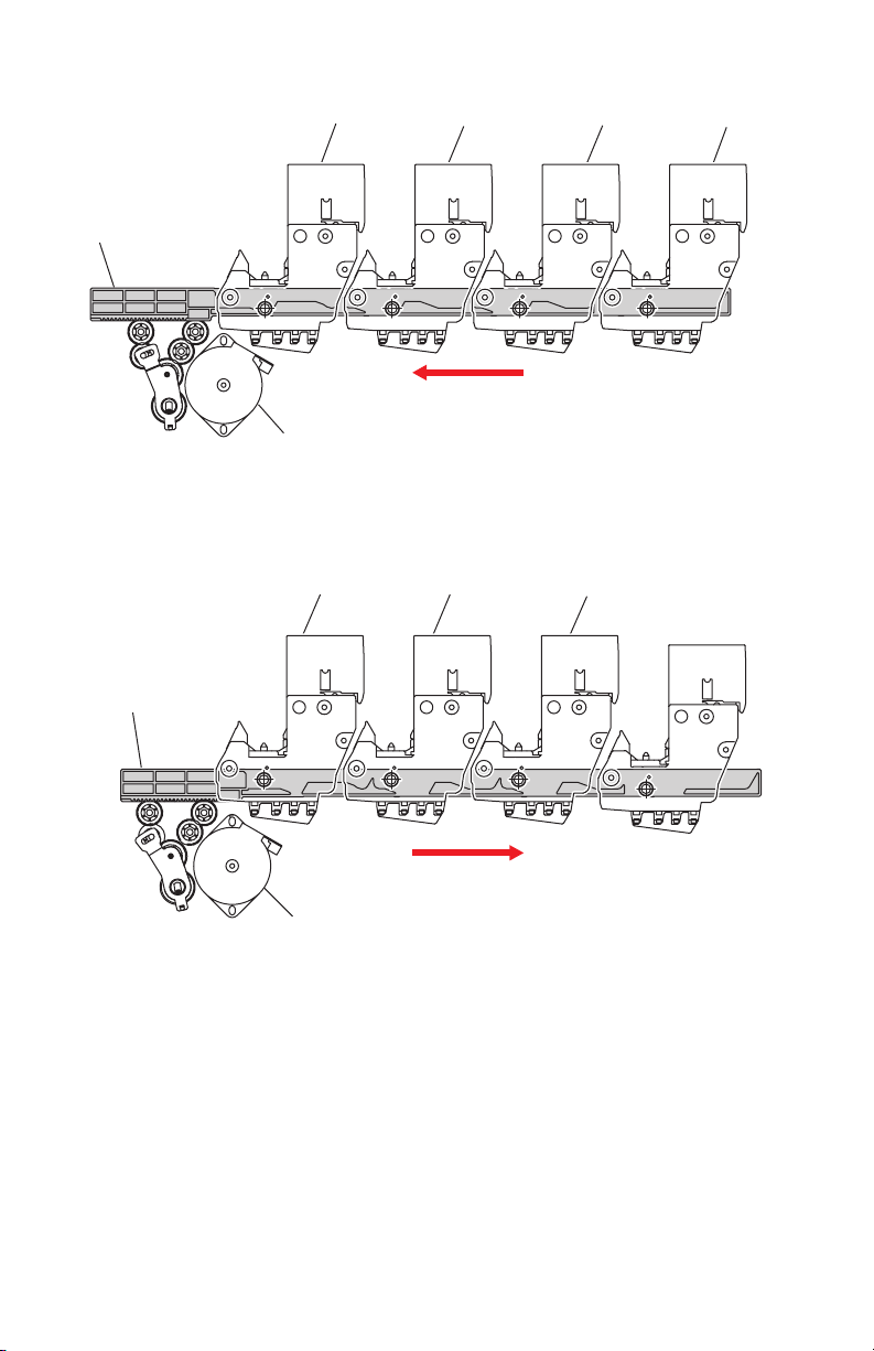
ID Unit Operations During Color Printing
C-ID Unit M-ID Unit
Lift Uplink
C-ID Motor
(CCW)
ID Unit Operations During Monochrome Printing
C-ID Unit M-ID Unit
Lift Uplink
Y-ID Unit
Y-ID Unit
K-ID Unit
K-ID Unit
C-ID Motor
(CW)
s7400-172
2-40 Phaser 7400 Color Printer Service Manual
Page 86

Imaging Unit Drive
The four Imaging Unit Motors supply the drive to the Imaging Unit drum and
Agitation Bar and Gear as shown in the following figure.
Imaging Unit Motor
Imaging Unit Drum
Agitation Gear
Agitation Bar
Imaging Unit
s7400-390
Transfer Unit Motor
The Transfer Unit motor turns clockwise driving the Transfer Unit belt. Inside the
Transfer Unit are four Transfer Rollers located just under each Imaging Unit drum.
When the Transfer Unit Motor and Imaging Unit Motors are activated, they carry the
paper on the transfer belt to the Fuser. The voltages applied to the Transfer Rollers
attract the toner image from the Imaging Unit drum to the media.
Theory of Operation 2-41
Page 87

Transfer Unit Motor
s7400-360
Transfer Unit Drive
The Transfer Unit Motor supplies the drive to the transfer belt as shown in the
following figure.
Transfer Unit Motor
Transfer Unit Gear
Transfer Unit Belt
Transfer Roller
Transfer Unit
s7400-391
2-42 Phaser 7400 Color Printer Service Manual
Page 88

Fuser Motor
The Fuser Motor drives the Fuser Heat and Pressure Rollers, as well as the Exit
Rollers. This is shown in the following figure.
Fuser Motor
Heat Roller
Pressure Roller
Exit Rollers
Fuser
s7400-392
Theory of Operation 2-43
Page 89

Toner Dispense Motors
The CM and YK Toner Dispense Motors are mounted above the Imaging Unit Motors
and drive the Toner Cartridge Supply Augers and Agitation Springs to deliver toner to
the Imaging Units.
Toner Dispense Motors
s7400-48
2-44 Phaser 7400 Color Printer Service Manual
Page 90

Duplex Drive Motors
Two motors are used to capture and transport paper in the Duplex Unit. Duplex Motor
A drives the Entrance Roller CCW to capture paper, then CW to drive the media into
the Transport Rollers. Motor B uses a series of belts to drive the four Transport
Rollers that move media to the Registration Assembly.
Duplex
Motor A
Duplex
Motor B
s7400-483
Theory of Operation 2-45
Page 91

Chassis Assemblies
Basket Assembly
The Basket Assembly allows all four Imaging Units to be raised from the Transfer
Unit to facilitate jam clearance. A latch at the front of the Basket Assembly releases
the locking catch.
Basket Assembly
s7400-395
The Basket Assembly is comprised of an upper and lower sub-assembly. The Upper
Basket Assembly attaches to the printer frame and supports the Lower Basket
Assembly. The Lower Basket Assembly connects to the Upper Basket Assembly and
supports the four Imaging Units and the Waste Toner Manifold. The Lower Basket
sub-assembly, or the entire Basket Assembly are available as replacement parts.
2-46 Phaser 7400 Color Printer Service Manual
Page 92

Waste Toner Recovery
Waste toner recovery moves the toner collected from the Imaging Unit drums and
Transfer Unit belt to the Waste Toner Reservoir located at the front of the printer.
Driven by the Waste Toner Motor, separate Augers in the Waste Toner Manifold and
Waste Toner Duct pull toner through a tube to the Waste Toner Reservoir. Waste toner
is moved within the reservoir by another Auger driven by the Waste Toner Motor.
Waste Toner
Auger Assembly
Transfer Unit
Waste Toner Chute
Waste Toner Reservoir
s7400-397
Status of the Waste Toner Reservoir is monitored by the Engine Control Board. The
Engine Control Board receives count signals from the Waste Toner Reservoir Auger
Rotation Sensor located behind the Right Front Cover. This Hall-Effect sensor is
activated each time a small, magnetic disk, embedded in the reservoir auger gear,
passes in front of the sensor. The auger revolutions are converted into a life count.
■ Waste Toner Reservoir Detect Switch
Detects the presence of the Waste Toner Reservoir.
■ Waste Toner Reservoir Full Sensor
Detects when the Waste Toner Reservoir is full.
■ Waste Toner Reservoir Auger Rotation Sensor
Detects revolutions of the reservoir auger.
■ Waste Toner Auger Rotation Sensor
Detects revolutions of the manifold auger.
■ Waste Toner Motor
Drives augers in the Waste Toner Manifold, Waste Toner Duct, and Waste Toner
Reservoir.
Theory of Operation 2-47
Page 93

Registration Assembly
Shown in the following figure are the components associated with the Registration
Assembly.
Temperature
Transfer Unit
Entrance Sensor
Media Thickness
Sensor
Tray 1 (MPT)
Home Position Sensor
Registration
Rollers #1
■ Tray 1 (MPT) Home Position Sensor
Detects the position of the Feed drive.
■ Registration Sensor #1
Detects the when the media’s leading edge has reached the Registration Rollers.
■ Registration Rollers #1
Driven by the Registration Motor through the Registration Clutch, the
Registration Rollers work to correct media skew and transport media to the
Transfer Unit belt.
Humidity Sensor
Registration
Clutch #1
Front Sensor Board
Registration
Sensor
s7400-644
■ Registration Clutch #1
Transfers drive from the Registration Motor to the Registration Rollers.
■ Transfer Unit Entrance Sensor
Detect the arrival of the media at the Transfer Unit.
■ Media Thickness Sensor
Produces a signal that varies dependent on media thickness.
■ Temperature/Humidity Sensor
Monitors environmental conditions surrounding the printer.
■ Front Sensor Board
Communicates the status of Tray 1 (MPT) and Registration Assembly sensors to
the Motor Driver Board.
2-48 Phaser 7400 Color Printer Service Manual
Page 94

Exit Assembly
The Exit Assembly uses rollers, solenoids, sensors, and diversion gates to handle
media exiting the Fuser.
Exit Assembly
s7400-396
Exit Assembly components include:
■ Exit Gate
The Exit Gate switches the paper path. When the Exit Gate is in its resting
position, paper is fed to the Top Output Tray. When it is lowered by the Exit Gate
Solenoid, paper is fed to the Side Output Tray or Duplex Unit.
■ Exit Gate Solenoid
Switches the paper discharge path between the Top and Side Output Trays.
■ Side Output Tray Full Stack Sensors
These sensors use an actuator to detect when the Top or Side Output Tray is full.
■ Fuser Exit Sensor
The Fuser Exit Sensor detects whether paper remains in the output rollers.
■ Door E Detect Sensor
Detects whether Door E is open or closed.
■ Side Output Tray Detect Sensor
Detects whether the Side Output Tray is open or closed.
Theory of Operation 2-49
Page 95

■ Offset Home Position Sensor
The Offset Home Position Sensor detects the roller position.
■ Job Offset Trailing Edge Sensor
Detects the trailing edge of the media as it leaves the Exit Assembly.
■ Exit Rollers
Driven by the Fuser Motor, the Exit Rollers transport media from the Fuser
through the Exit Assembly. Exit Roller drive gearing is shown in the following
figure.
Eject Idle
Gear Z27
Eject Idle
Gear Z54
Eject Idle
Gear Z27
Eject Gear Z17
Eject Gear Z17
s7400-406
■ Duplex Gate
Actuated by the Duplex Gate Solenoid in the Duplex Unit, the Duplex Gate
directs media through the upper portion of the Duplex Unit and returns it to the
Registration Assembly for printing on side 2. The following figure shows the
Duplex Gate linkage between the Duplex Unit and Exit Assembly
2-50 Phaser 7400 Color Printer Service Manual
Page 96

Exit Assembly
Duplex Unit
Job Offset Assembly
s7400-407
■ Job Offset Motor
The Offset Motor acting through the Offset Gear shifts the media forward or
backward providing offset capability. The flow diagram shows the components
involved in the offset process.
OFFSET MOTOR
OFFSET GEAR
OFFSET CHUTE
OFFSET ROLLER
-
■ Top Output Tray Full Stack Actuator
Acutates the Top Output Tray Full Stack Sensor to limit the number of sheets
sent to the tray.
Theory of Operation 2-51
Page 97

Trays
Standard input trays include the 100-sheet, multi-purpose Tray 1 (MPT) and one
550-sheet universal tray. Standard output trays include a 500-Sheet facedown Top
Output Tray with offset capability, and a 250-sheet faceup Side Output Tray.
Tray 1 (MPT)
The Tray 1 (MPT) feeds standard and custom size media into the printer. The printer’s
Feed Motor, shared with Tray 2, drives the Tray 1 (MPT) Feed Roller to feed media
from the tray. Tray 1 (MPT) components include:
■ Feed Rollers (Feed Retard and Pick)
Transport media from Tray 1 (MPT) to the Registration Assembly.
■ Tray 1 (MPT) No Paper Sensor
Detects when media is in Tray 1 (MPT).
■ Tray 1 (MPT) Level Sensor
Detects the presence of media at the Pick Roller.
■ Tray 1 (MPT) Home Position Sensor
Located in the Registration Assembly, it detects the position of the Feed drive.
■ Feed-Out Sensor #1
Detects media exiting the Tray 1 (MPT) Feed Rollers
■ OHP Sensor
Detects when transparency media is being fed to the Registration Assembly.
Feed-Out Sensor #1
Door A Interlock Switch
Level Sensor
No Paper Sensor
Pick Roller
Retard Roller
Feed Roller
Tray 1 (MPT)
Home Position Sensor
s7400-399
2-52 Phaser 7400 Color Printer Service Manual
Page 98

Tray 1 (MPT) incorporates a single set of guides to establish paper width. The time
required for the paper to clear the No Paper Sensor identifies the paper’s length. When
media is placed in Tray 1 (MPT), the leading edge strikes the actuator of the No Paper
Sensor indicating the presence of paper. As the last sheet of paper is fed from the tray
the actuator drops through an opening indicating No Paper remains in the tray.
Universal Trays
The universal trays 2 through 6 include end and side guides that manually adjust to
the paper loaded in the tray. These guides come into contact with the front and rear
edges of the paper and hold it in position. Paper size is determined by the signal
created by the guides interacting with the Paper Size Switch actuators.
End Guide
Rear Side Guide
Lift Plate
Front Side Guide
s7400-199
■ Side Guides Right and Left
The side guides move against media to align or register the width of print media
in the paper feed direction.
■ Rear Guide
The Rear Guide moves to determine the length of print media in the paper feed
direction. The Rear Guide contacts the Paper Size Switch actuators to detect the
paper size loaded in the tray.
■ Lift Plate
The Lift Plate is raised by the Lift Motor to position the media for picking.
Theory of Operation 2-53
Page 99

Universal Feeder
Universal Feeder
Feeder Board
Level Sensor
No Paper Sensor
Feed-Out Sensor
s7400-571
■ Level Sensor
The Level Sensor uses an actuator to determine whether paper in the tray is lifted
to the optimum feeding position. When the flag of the actuator leaves the sensing
area, the sensor detects that the paper has been lifted.
■ Feed-Out Sensor
The Feed-Out Sensor detects a paper jam in the tray by the paper position and
sensor transition time.
■ No Paper Sensor
The No Paper Sensor uses an actuator to determine whether the tray is empty.
When the actuator lowers, the No Paper Sensor signal goes High indicating an
empty tray.
■ Feeder Board
The Feeder Board communicates sensor information to the Motor Driver Board.
Side Output Tray
The Side Output Tray provides 250-sheets of faceup output capacity. Included is a
Paper Support that rotates 180 degrees to support the stack, and a latching door for
printers equipped with a Finisher. Stack level is monitored by The Side Output Tray
Full Stack Sensor mounted in the Exit Assembly.
2-54 Phaser 7400 Color Printer Service Manual
Page 100

Electrical
The following provides an overview of the major electrical components. Additional
detail is located in Section 10, Wiring Diagrams.
LED Relay Board
Registration Sensor Board
CRUM Reader Board
Rear Sensor Board
CRUM Antenna
Duplex Control Board
Control Panel
Imaging Unit
Sensor Board
Front Sensor Board
s7400-410
IP Board
Engine Control Board
Motor Driver
Board
LVP S
HVPS
s7400-411
Theory of Operation 2-55
 Loading...