

Page 1

PHASER® 740 and 750
LASER PRINTERS
Service Quick Reference Guide
Warning
The following servicing instructions are for
use by qualified service personnel only. To
avoid personal injury, do not perform any
servicing other than that contained in
operating instructions unless you are qualified
to do so.
This printing: Febuary 2000
063-3102-01
Page 2

Copyright © 1998 by T ektr onix, Inc., Wilsonville, Oregon. Printed in the United States
of America. All rights reserved. Contents of this publication may not be reproduced
in any form without permission of Tektronix, Inc.
®
Tektronix
Tektronix, Inc. TekColor™, PhaserShare™, PhaserMatch™, PhaserLink™,
Finepoint™ and PhaserPrint™ are trademarks of Tektronix, Inc. RealSUPPORT
and TekColor Care
, Phaser®, and Made for Each Other® are registered trademarks of
SM
are service marks of Tektronix, Inc.
SM
Other marks are trademarks or registered trademarks of the companies with which
they are associated.
TE/mq/mm
Page 3

Users safety summary
Terms in
manual:
Power source:
the supply conductors or between either supply conductor and ground. Use only the
specified power cord and connector. For 220 VAC printers, Do not apply more than
250 volts RMS between the supply conductors or between either supply conductor
and ground. Use only the specified power cord and connector.Refer to a qualified
service technician for changes to the cord or connector.
Operation of product:
to replace fuses inside the product. Do not operate without the covers and panels
properly installed. Do not operate in an atmosphere of explosive gases.
Safety instructions:
product into a power source.
Terms on
product:
CAUTION Conditions that can result in damage to the product.
WARNING Conditions that can result in personal injury
or loss of life.
For 110 VAC printers, Do not apply more than 130 volts RMS between
Avoid electric shock by contacting a qualified service technician
WARNING Turning the power off using the On/Off switch does
not de-energize the printer. You must remove the power cord to
disconnect the printer from the mains. Keep the power cord
accessible for removal in case of an emergency.
Read all installation instructions carefully before you plug the
CAUTION A personal injury hazard exists that may not be
apparent. For example, a panel may cover the hazardous area.
Also applies to a hazard to property including the product itself.
DANGER A personal injury hazard exists in the area where
you see the sign.
Care of product:
Disconnect the power plug if the power cord or plug is frayed or otherwise damaged,
if you spill anything into the case, if product is exposed to any excess moisture, if
product is dropped or damaged, if you suspect that the product needs servicing or
repair, and whenever you clean the product.
Ground the product:
grounded AC outlets only. If necessary, contact a licensed electrician to install a
properly grounded outlet.
Disconnect the power plug by pulling the plug, not the cord.
Plug the three-wire power cord (with grounding prong) into
Page 4
Symbols as marked on product:
DANGER high voltage:
Protective ground (earth) terminal:
Use caution. Refer to the manual(s) for information:
!
Laser use caution. Refer to the manual(s) for information:
WARNING:
(and other conductive parts) can cause an electrical shock. Electrical product may be
hazardous if misused.
If the product loses the ground connection, usage of knobs and controls
Page 5
Service safety summary
For qualified service personnel only:
Do not service alone:
Do not perform internal service or adjustment of this product
Refer also to the preceding Users Safety Summary.
unless another person capable of rendering first aid or resuscitation is present.
Use care when servicing with power on:
Dangerous voltages may exist at several points
in this product. To avoid personal injury, do not touch exposed connections and
components while power is on.
Disconnect power before removing the power supply shield, soldering, or replacing
components.
Do not wear jewelry:
Remove jewelry prior to servicing. Rings, necklaces, and other
metallic objects could come into contact with dangerous voltages and currents.
Power source:
This product is intended to operate from a power source that will not
apply more than 250 volts rms between the supply conductors or between either
supply conductor and ground. A protective ground connection by way of the
grounding conductor in the power cord is essential for safe operation.
This product is certified under IEC 825 as a Class 1 Laser Product.
DANGER:
Invisible laser radiation
when open and interlock
defeated.
AVOID DIRECT
EXPOSURE TO BEAM.
PELIGRO:
Cuando se abre y se
invalida el bloqueo, se
producen radiaciones
invisibles de láser.
EVITESE LA
´
EXPOSICION
DIRECTA A TALES
RAYOS.
CAUTION:
Invisible laser radiation
when open and
interlocks defeated.
AVOID DIRECT
EXPOSURE TO BEAM.
VARNING:
Osynlig laserstrálning när denna
del är öppnad och
spärrar är
urkopplade.
STRÅLEN
ÄR FARLIG.
VORSICHT:
Unsichtbare Laserstrahlung,
wenn Abdeckung geöffnet
und Sicherheitsverriegelung
überbrückt.
NICH DEM STRAHL
AUSSETZEN.
VAROI:
Näkymätön
avattaessa ja
suojalukitus
ohitettaessa olet
alttiina lasersäteilylle.
ÄLÄ KATSO
SÄTEESEN.
ATTENTION:
Rayonnement laser invisible
dangereux en cas
d'ouverture et lorsque
la sécurité est neutralisée.
EXPOSITION DANGEREUSE
AU FAISCEAU.
VARNING:
Osynlig laserstrálning
när denna del är
öppnad och spärrar är
urkopplade.
BETRAKTA EJ
STRÅLEN.
ADVARSEL:
Usynlig laserstràling
ved abning når
sikkerhedsafbrydere
er ude af funktion.
UNDGÅ UD
ÆTTELSE FOR
STRÅLING.
Class 3B
ADVARSEL:
Usynlig laserstraling
nar deksel åpnes og
sikkerhedslas brytes.
UNNGÅ
EKSPONERING
FOR STRÅLEN.
PJQT4521ZA
9008-78
Page 6

Page 7

Contents
General Information 1
The Phaser 740 Color Printer 2
The Phaser 750 Color Printer 4
Phaser 740 printer RAM and printer capabilities 6
Phaser 750 printer RAM and printer capabilities 8
Print engine assemblies 10
The image processor board 13
Phaser 740 13
Phaser 750 14
Front panel 15
Rear panel 17
Test print button 17
Network card LEDs 18
Health LED (Phaser 740 only) 20
Media tray type sensing 20
Difference between Phaser 740 and 750 22
Specifications 23
Regulatory specifications 26
Error Codes and Messages 27
Error messages 27
Print engine error codes 27
Normal power-up self-tests 35
Troubleshooting 37
System power-up sequence 37
Print engine troubleshooting 38
Testing the print engine 38
Verifying printer operation by using its self-test print 39
Verifying power supply operation 39
Measuring power supply voltages 39
Inspecting the power supply fuses 41
Safety interlocks 41
Testing for a shorted motor 42
Media jams and the paper path 43
Media-based problems 43
Media problems 43
Multiple-sheet pick 44
The media skews passing through the paper path 44
Paper tray indicates empty when it is not 44
No paper feeder installed 45
No imaging unit installed 45
Service Guide
vii
Page 8

Jams 46
Wrong media 46
Paper mis-picks at the paper tray 46
Paper jams midway in the paper feeder 46
Paper jams at the second bias transfer roller 47
Fuser jams 48
Eject jams 48
Multi-purpose tray feed jams 49
Jams in the duplex unit 49
Other problems 50
The printer continuously displays “Initializing” 50
No toner cartridge installed message when it is 50
No fuser installed message when it is 50
No fuser roll installed message when it is 51
Front door open when it is closed 51
Left-side door open message when it is not 51
High temperature error 52
Low temperature error 52
High voltage error 52
Thermistor open error 52
Front panel cycling between READY and WARMING UP 53
Erratic printer behavior 53
Installed RAM not recognized 53
Printing and print quality problems 54
Blank print 56
All-black print 56
Single color mottled or with non-uniform density streaks 57
Dark vertical line in print, single color 57
Vertical line in print, all colors 57
Vertical line or scratch in print, single color 58
Vertical line or scratch in print, all colors 58
Small, repeating light dot in one color in-line with each other 59
Single light, horizontal line in all the prints 60
Large, random light smudges 60
One or more dark vertical line in all colors 61
Dark, irregular, vertical streaks and smears on the entire page 62
One primary color faded or pale OR a single color has a dark vertical streak
62
Light, faded, pale prints 63
Single white spot appear in the same place on the print 64
Contamination of one color by another 64
Missing primary color 65
Mis-transfer, missing portions of toner 65
Dirty background 66
Stains on the back of the print 66
Ghosting 66
Unfused or partially fused printing 66
Image is skewed on the paper 67
No printing on edge of print 67
Image is not centered on the print when it should be 67
viii
Phaser 740 and 750 Color Printers
Page 9

The print is wrinkled 68
Macintosh printing problems 69
Image never prints 69
Image is rotated 90 degrees 69
Image prints in black-and-white 69
Printer isn’t in the Chooser 70
Windows printing problems 70
Image never prints 70
Interpreting the Supplies Page 71
Life remaining gauges 71
Date installed 71
Toner coverage 71
Print counts 71
Print count conversions 72
Service Tests and Adjustments 73
Required tools 73
Printing test prints on the Phaser 740 printer 74
Print service test prints 74
Printing the Configuration Page 74
Printing the demonstration pages 74
Printing the print engine’s test print 74
Printing test prints on the Phaser 750 printer 75
Printing the Diagnostic Test Pages and Solid Fill Test Page 75
Printing the Configuration Page 75
Printing the demonstration pages 75
Printing the print engine’s test print 75
Embedded pages (Phaser 750 printer only) 76
Printer self-diagnostics 77
Phaser 740 service tests 77
Phaser 750 service tests 80
Print engine calibration 84
Printer color correction 84
Manually setting color corrections 84
Phaser 740 84
Phaser 750 84
Calibrate for paper (Phaser 750 only) 86
Cleaning and Maintenance 87
Service preventive maintenance procedure 87
Recommended tools 88
Cleaning 88
Lubrication 89
Service Guide
ix
Page 10

Resetting NVRAM 91
Phaser 740 printer 91
Phaser 750 printer 91
Key FRU Disassembly 93
Printer cabinet 93
EMI shields 95
Cartridge selector/eject unit (right door) 96
Paper feeder and tray sensor board 98
Multi-purpose tray pick roller 99
Cork separator pad 100
Laser scanner 101
Power supply 102
Main motor 103
Paper feed motor 103
Toner cartridge drive motor 103
Cleaning board 103
Toner cartridge drive unit 104
Accumulator belt home position sensor 104
Left door open interlock switch 104
Temperature/humidity sensor board 105
Pre-exposure lamp 105
Pre-transfer lamp 105
Paper feed/fuser gear train 106
Tray guides 107
Engine control board 108
High-voltage board 109
Image processor board 110
Phaser 740 110
Phaser 750 111
FRU List 113
Supplies and accessories 125
Test Prints 131
Phaser 740 printer test prints 131
Phaser 750 printer test prints 132
Wiring Diagram 135
x
Phaser 740 and 750 Color Printers
Page 11

Figures
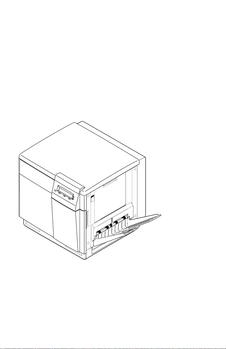
The Phaser 740/750 Color Printer 1
Print engine major components 10
Print engine components (continued) 11
Print engine sensor, switch and solenoid locations 12
Features of the image processor board 13
Features of the image processor board 14
The front panel 16
The Phaser 740 rear panel 19
The Phaser 750 rear panel 19
Tray switch sensors and actuators 21
Measuring the DC voltages (test points) 40
Door safety interlock switches 42
Troubleshooting print quality problems 54
Manual color correction reference print 85
The Calibrate for Paper test page 86
Removing cabinet covers 93
Removing cabinet covers 94
Removing the EMI shields 95
Removing the cartridge selector/eject unit 97
Removing the paper feeder 98
Removing the multi-purpose tray pick roller 99
Removing the cork separator pad 100
Removing the laser scanner and driver board 101
Removing the power supply 102
Removing the main motor, paper-feed motor, toner cartridge drive motor and cleaning
board 103
Removing the toner cartridge drive unit, home position sensor and the left door interlock
switch 104
Removing the temperature/humidity sensor board 105
Removing the pre-exposure lamp and pre-transfer lamp 105
Removing the gear train 106
Removing the tray guides 107
Removing the engine control board 108
Removing the high-voltage board 109
Removing the image processor board 110
Removing the image processor board 111
Cabinet FRUs 114
Cabinet FRUs 115
Motor and fan FRUs 117
Sensor, switch and flag FRUs 119
Service Guide
xi
Page 12

Circuit board and electronic FRUs 121
Imaging and paper feed component FRUs 123
Wiring diagram 135
Tables
Installed RAM and printer capabilities 6
Installed RAM and printer capabilities 8
Tray switch sensor combinations 20
Summary of differences between Phaser 740 and Phaser 750 22
Physical dimensions 23
Printer clearances 23
Functional specifications 24
Electrical specifications 25
Environmental specifications 25
Print engine service error codes 27
Normal power up error codes 35
Phaser 740 print engine service test descriptions 77
Phaser 750 print engine service test descriptions 80
FRU parts list of the printer cabinet 114
FRU part list of the printer cabinet 115
Motors, drive units and fans 116
Sensors, switches and flags 118
Circuit board and electronics 120
Imaging and paper feed components 122
Kits and other hardware 124
Common supplies and accessories 125
Phaser 740 Supplies and accessories 125
Phaser 750 Supplies and accessories 128
xii
Phaser 740 and 750 Color Printers
Page 13
General Information
A4A4
PAPE
R
ER
This service guide contains information useful for troubleshooting, repairing,
adjusting, and maintaining Tektronix Phaser
®
740, 740L, and 750 Color Printers. This
manual includes troubleshooting guides, adjustment procedures and a field
replaceable units (FRU) list.
Topics such as printer theory of operation, detailed removal/replacement procedures,
configuration page details, and verifying printer operation are located on the
companion
Color Printer Service & Support Resources CD-ROM
.
To ensure a complete understanding of the product, we recommend participation in
Phaser 740 and 750 printer service training.
The Phaser 740/750 Color Printer
3102-01
Service Guide
1
Page 14

The Phaser 740 Color Printer
The Phaser 740 Color Printer combines a color laser print engine with an image
processor supporting Adobe’s PostScript Level 3 page description language. The
image processor features a bi-directional parallel interface and a 10baseT Ethernet
port for host communication. Optional network adapter cards to the image pr ocessor
allow the printer to communicate on networks using LocalTalk, Ethernet 100baseT or
Token Ring protocols. The Ethernet network card supports EtherTalk 100baseT,
Novell and TCP/IP. With the Token Ring network card, the printer supports Token
Ring protocols. With 32 Mbytes of RAM installed, the printer supports the color
PCL5C printer language too.
The printer is available in four configurations:
■
The
Phaser 740L
customer-upgraded to be a color printer. It prints at a resolution of 600 x
600. It is equipped with 16 Mbytes of RAM which can be supplemented
with an additional RAM DIMM. The printer contains 136 standard, built-in
fonts. The Phaser 740L is identical to the Phaser 740 except is set to only use
a black toner cartridge. It features a removable plate which blocks out the
locations of the color cartridges.
■
The
Phaser 740 Base
supplemented with one or two additional 16-, 32-, 64- and 128-Mbyte RAM
DIMMs; maximum usable capacity is 80 Mbytes. The printer contains 136
standard, built-in fonts. The printer contains 136 standard, built-in fonts.
The Phaser 740 Base prints at a resolution of 600 x 600 dots-per-inch.
■
The
Phaser 740 Plus
total) and a SCSI interface board. The presence of the SCSI board (and the
extra memory) enables the printer to print at higher resolutions 1200 x 1200
(Premium mode) dots-per-inch and also support image pipelining for
greater throughput, a print collation mode, and a “check print before
proceeding with job” mode. The printer contains 136 standard, built-in
fonts.
is a monochrome version of the printer which can easily be
comes standard with 32 Mbytes of RAM which can be
includes 32 Mbytes of additional memory (64 Mbytes
■
The
Phaser 740 Extended
SIMM than the other printers. It includes 128 Mbytes total memory, SCSI
port, 1200 x 1200 color printing, check print mode, print job collation
(requires hard drive), copystation support and print pipelining.
The color printers support a 5.3 page-per-minute, composite-black printing “Fast
Color” mode which prints at 600 x 600 dpi using three passes, cyan, magenta and
yellow, to produce an image instead of the usual four passes, cyan, magenta, yellow
and black. Each printer also features “Presentation” mode printing in which a paper
print is printed with the color settings of a transparency print. Presentation mode
produces the smoothest and brightest large-area fills. The printer prints in
monochrome at 16 prints-per-minute.
2
Phaser 740 and 750 Color Printers
(a factory-only option) features a different ROM
Page 15

Print speeds depend on the chosen resolution and selected media. For resolutions of
600 x 600 (standard), in color, the printer prints at 4 pages per minute (ppm) on paper.
Monochrome printing (Fast Monochrome) is at 16 ppm on paper. Transparency film
printing is always 2 ppm. For 1200 x 1200 (premium) dpi color printing, the printer
color prints at 2 ppm. Monochrome printing is at 8 ppm. The printer prints 600 x 600
dpi, composite black (CMY) draft prints at a rate of 5.3 pages-per-minute.
The plus and extended features option includes a SCSI-compatible interface to connect
to an external hard disk drive for additional font storage. The hard disk drive is also
required for print collation of multiple copy multi-page prints. A copy unit can also
be connected to the printer’s SCSI port to give the printer the ability to optically copy
color images. An factory-only, internal IDE hard drive can be installed in the printer
in place of the network card.
The printers support printing on A-, A4- and Legal-sized paper and transpar ency film
from separate A or A4- or Legal-size trays. An optional two-tray second feeder (called
the Lower Tray Assembly) is available. The printer features a built-in multi-purpose
tray from which specialty media, cardstock and envelopes can be fed. The printer also
supports manual feeding using the multi-purpose tray.
An optional auto-duplex unit allows the printer to automatically create two-sided
prints. The duplex unit takes the place of the main (top) tray. The duplex unit
requires using the optional two-tray second feeder as a paper sour ce. The duplex unit
upgrade kit includes the optional two-tray feeder. When printing double-sided, print
times are generally doubled. Two-sided monochrome printing is at 4 ppm, two-sided
color at 2 ppm.
After being idle for the selected amount of time the printer switches into its Energy
Star mode where it consumes less than 45 watts of power. It “awakens” upon
receiving data at any of its ports.
Service Guide
3
Page 16

The Phaser 750 Color Printer
The Phaser 750 Color Printer combines a color laser print engine with an image
processor supporting Adobe’s PostScript Level 3 page description language. The
image processor features a bi-directional parallel interface and an Ethernet port for
host communication. The Ethernet port supports EtherTalk 10/100baseT, Novell and
TCP/IP. An optional network adapter card allow the printer to communicate with
Token Ring networks. A USB port is available on the rear panel to directly connect
with a USB-compatible host. The printer supports the color PCL5C printer language
too.
The printer is available in four configurations:
■
The
Phaser 750N
supplemented with an additional 32-, 64- and 128-Mbyte RAM DIMM;
maximum usable capacity is 256 Mbytes. The printer contains 136 standard,
built-in fonts. The printer contains 136 standard, built-in fonts. The Phaser
750N prints at a color resolution of 1200 x 600 dots-per-inch.
■
The
Phaser 750P
of memory and can print at a higher resolution of 1200 x 1200 dots-per-inch
(Premium mode). The Phaser 750P also support image pipelining for
greater throughput, a print collation mode (which requires the hard drive
option), and a “First Page Preview” mode.
■
The
Phaser 750DP
printer but includes 128 Mbytes of RAM and a Lower Tray Assembly and
Duplex Unit.
■
The
Phaser 750DX
Phaser 750DP printers but includes an internal hard drive which enables
Print Collation mode. The hard drive also is pre-loaded with manuals,
videos and printer drivers.
comes standard with 64 Mbytes of RAM which can be
is the same as the Phaser 750N except it includes 96 Mbytes
has all the features and capabilities of the Phaser 750P
has all the features, RAM, and capabilities of the
The color printers support a 5.3 page-per-minute, composite-black printing “Fast
Color” mode which prints at 600 x 600 dpi using three passes, cyan, magenta and
yellow, to produce an image instead of the usual four passes, cyan, magenta, yellow
and black.
Print speeds depend on the chosen resolution and selected media. For resolutions of
1200 x 600 (Enhanced), in color, the printer prints at 4 pages per minute (ppm) on
paper. Monochrome printing (Fast Monochrome) is at 16 ppm on paper.
Transparency film printing is always 2 ppm. For 1200 x 1200 (Premium) dpi color
printing, the printer color prints at 2 ppm. Monochrome printing is at 8 ppm. The
printer prints 600 x 600 dpi, composite black (CMY) draft prints at a rate of 5.3 pagesper-minute.
The printers support printing on A-, A4- and Legal-sized paper and transpar ency film
from separate A or A4- or Legal-size trays. An optional two-tray second feeder (called
the Lower Tray Assembly) is available. The printer features a built-in multi-purpose
tray from which specialty media, cardstock and envelopes can be fed. The printer also
supports manual feeding using the multi-purpose tray.
4
Phaser 740 and 750 Color Printers
Page 17

An optional duplex unit allows the printer to automatically create two-sided prints.
The duplex unit takes the place of the main (top) tray. The duplex unit requires using
the optional two-tray second feeder as a paper source. The duplex unit upgrade kit
includes the optional two-tray feeder. When printing double-sided, print times are
generally doubled since both sides of a print are printed. Two-sided monochrome
printing is at 4 ppm, two-sided color at 2 ppm.
After being idle for the selected amount of time the printer switches into its Energy
Star mode where it consumes less than 45 watts of power. It “awakens” upon
receiving data at any of its ports.
The printer features Intelligent Ready software which monitors when and how the
printer is used. Tracking these patterns over a rolling 3-week period, the printer
automatically places itself in standby power-saving modes during periods of non-use.
The printer automatically returns to Ready mode, just prior to a a use period, to avoid
having users wait for the printer to warm up.
Service Guide
5
Page 18

Phaser 740 printer RAM and printer capabilities
The Phaser 740 printer features two DIMM connectors which accept both 16-, 32-, 64-,
and 128-Mbytes RAM DIMMs. The printer can use off-the-shelf RAM meeting these
specifications:
■
168-pin DIMM
■
Synchronous DRAM
■
3.3 volt
■
9 nsec speed
■
Valid on-board Serial Presence Detect ROM.
The Configuration Page lists the amount of installed RAM and the details; such as
type, parity, size, and manufacturer, about the DIMM installed in each slot.
Upon power-up, the image processor interrogates the 256 byte Serial Presence Detect
ROM which describes the DIMM with details such as data width, clock delay, number
of address columns and row, refresh rate and more. If the DIMM does not meets the
required specifications it will be ignored; no error message will be reported.
With more memory the printer gains the capabilities of printing at higher resolutions,
printing without having to use image compression (which trades off less installed
RAM for longer image processing time) and dual frame buffers for printing one image
while processing a second image (which gives greater printing throughput). With
additional RAM memory the printer’s capabilities increase as detailed in the
following table:
Installed RAM and printer capabilities
Feature 16 Mbytes 32 Mbytes 64 MBytes 80 Mbyte
600 x 600 dpi Color/mono Color/mono Color/mono Color/mono
1200 x 1200 dpi Black and white
Pipelining Yes, if SCSI
Frame buffer 1 Letter size
Check print Yes, if SCSI
Collation
(requires hard
drive)
6
only
image with
compression
Phaser 740 and 750 Color Printers
Black and white
only
1 Letter size
image with no
compression
Color and black
and white
board installed
2 Letter-size
images with
compression
board installed
Yes, if SCSI
board installed
Color and black
and white
Yes, if SCSI
board installed
2 Letter-sized
frame buffers
with no image
compression
Yes, if SCSI
board installed
Yes, if SCSI
board installed
Page 19

Print the Configuration Page and check the item “installed RAM” to see what type of
RAM is installed.
For example:
Installed RAM: 64 Mbytes
Mem slot 1: SDRAM/parity/64 MB/KMM366S824AT
Mem slot 2: empty
This is a list of DRAM SIMMs that are branded for use by Tektronix at the time this
guide was published:
Size
16 Mbyte Samsung KMM366S203BT
32 Mbyte Samsung KMM366S403BT
32 Mbyte Samsung KMM3665403CTL-G0
64 Mbyte Samsung KMM366S824AT
64 Mbyte Samsung KMM3665823BTL-G0
128 Mbyte Samsung KMM366S1623AT
32 Mbyte Smart Module SM564043574N6AA
64 Mbyte Smart Module SM564088574N6AA
32 Mbyte NEC MC-454AD645F-A10B
64 Mbyte NEC MC-454CB645FA-A10B
128 Mbyte NEC MC-4516CD645FZ-A10B
16 Mbyte Micron Tech. MT8LSDT264AG-66CL2
32 Mbyte Micron Tech. MT16LSDT264AG-10BC4
32 Mbyte Micron Tech. MT16LSDT264AG-662C1
32 Mbyte Micron Tech. MT16LSDT464A6-662xx
Maker Part Number
64 Mbyte Micron Tech. MT8LSDT864AG-662D3
64 Mbyte Micron Tech. MT8LSDT864AG-10BD2
64 Mbyte Micron/Crucial CT8M6454D10-MBT66LP
128 Mbyte Micron Tech. MT16LSDT1664AG-662DT
Service Guide
7
Page 20

Phaser 750 printer RAM and printer capabilities
The Phaser 750 printer features two DIMM connectors which accept 32-, 64-, and 128Mbytes RAM modules. The printer can use off-the-shelf SODIMM meeting these
specifications:
■
144-pin SODIMM
■
Synchronous DRAM
■
PC-100 compliant
■
3.3 volt
■
Valid on-board Serial Presence Detect ROM.
The Configuration Page lists the amount of installed RAM and the details; such as
type, parity, size, and manufacturer, about the module installed in each slot.
With more memory the printer gains the capabilities of printing at higher resolutions,
printing without having to use image compression (which trades off less installed
RAM for longer image processing time) and dual frame buffers for printing one image
while processing a second image (which gives greater printing throughput). With
additional RAM memory the printer’s capabilities increase as detailed in the
following table:
Installed RAM and printer capabilities
Feature 750N
1200 x 600 dpi Color/mono Color/mono Color/mono
1200 x 1200 dpi No Color Color
Pipelining Yes Yes
Frame buffer 1 Letter size image
Check print No Yes Yes
Collation (requires hard
drive)
64 Mbytes
with no
compression
No Yes Yes
750P
96 MBytes
2 Letter-size
images with
compression
750DP/DX
128 Mbyte
2 Letter-sized frame
buffers with no
image compression
8
Phaser 740 and 750 Color Printers
Page 21

Print the Configuration Page and check the item “installed RAM” to see what type of
RAM is installed.
For example:
Installed RAM: 64 Mbytes
Memory Slot 1: SDRAM/parity/64 MB/8LSDT864HG-10EB5
Memory Slot 2: empty
This is a list of DRAM SIMMs that are branded for use by Tektronix at the time this
guide was published:
Size
32MB Micron MT4LSDT464HG-10E
64MB Micron MT8LSDT864HG-10E
128MB Micron MT8LSDT1664HG-10E
Maker Part Number
Service Guide
9
Page 22
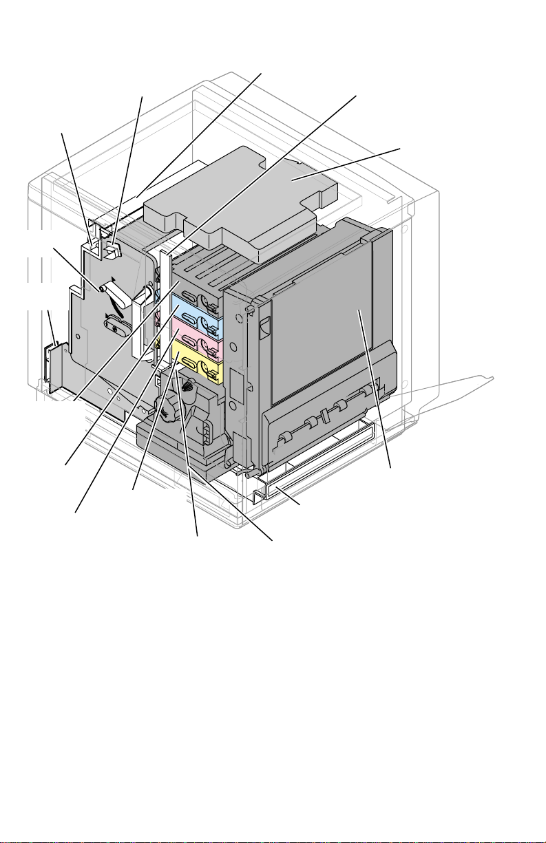
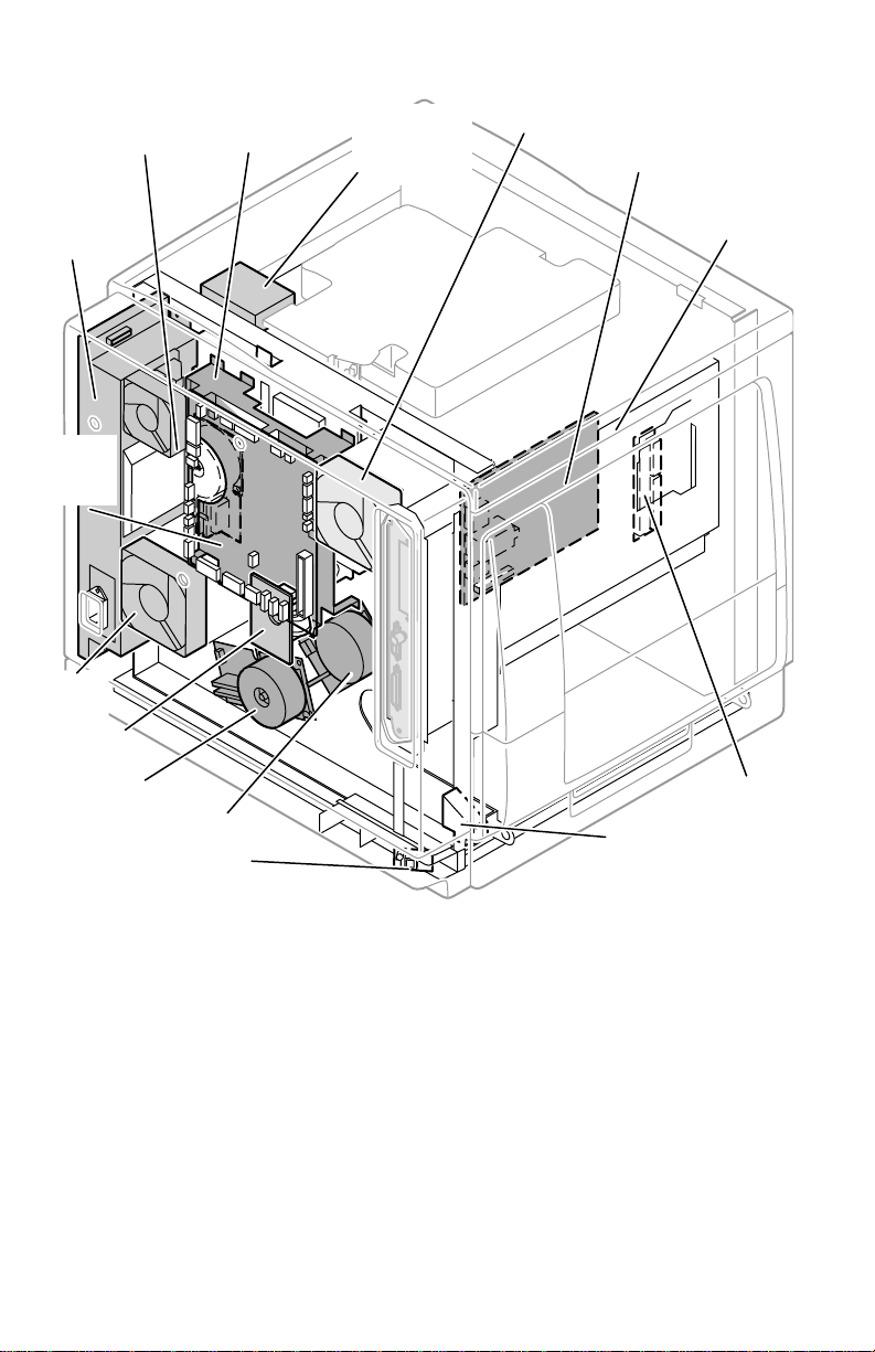
Print engine assemblies
A4
2
Pre-exposure
lamp
Imaging
unit
Paper
feeder
Black
toner
cartridge
Cyan toner
cartridge
Magenta
toner
cartridge
Main charger
corona unit
Yellow toner
cartridge
Pre-transfer lamp
Ozone filter
4
A
Paper tray
Fuser
Toner level
sensor board
Laser scanner
Toner cartridge
selector/paper
exit unit
(right door)
3102-0
Print engine major components
10
Phaser 740 and 750 Color Printers
Page 23
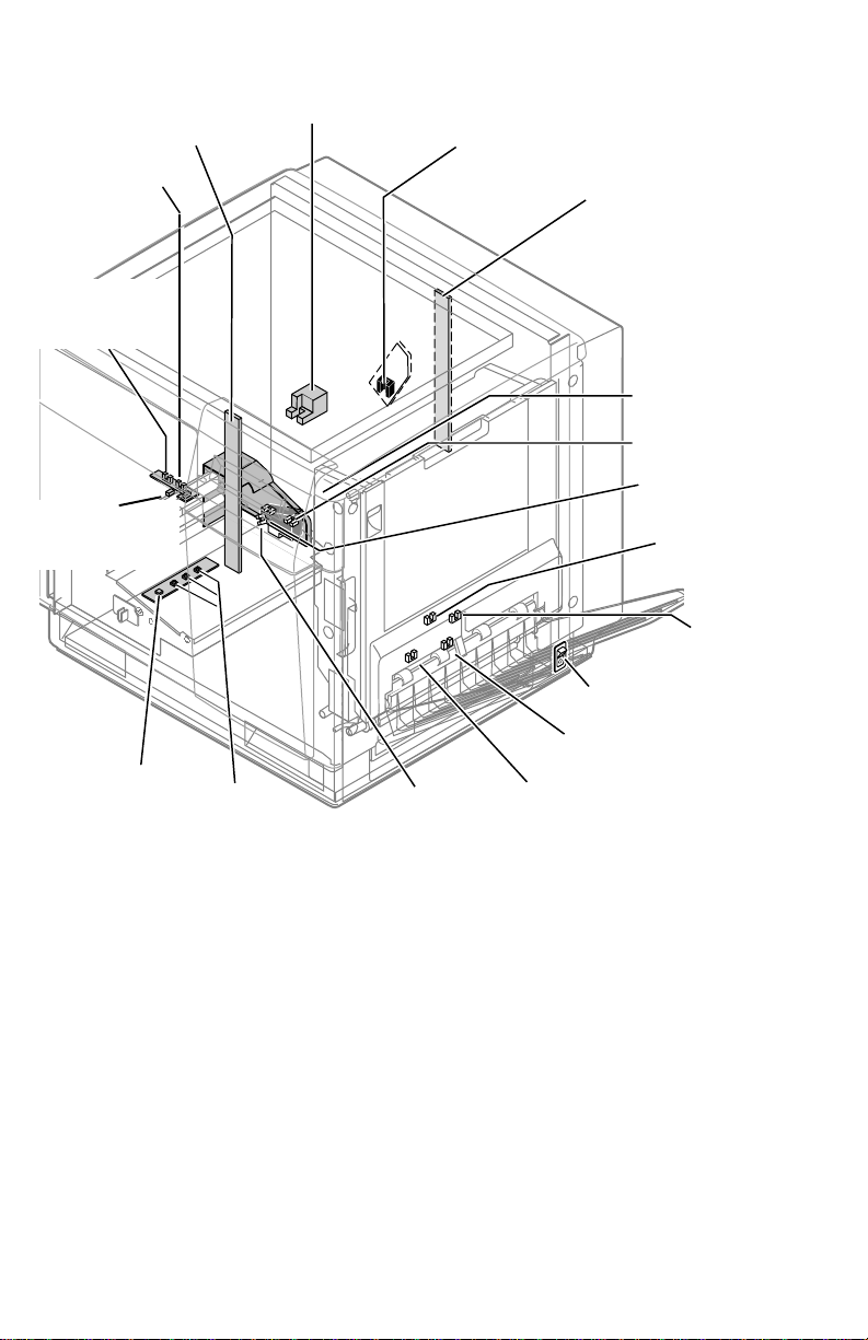
Toner
cartridge
Toner cartridge
drive unit
motor
Power
supply
unit
Engine
control
board
user
an
leaning
oard
aper feed motor
Main motor
emperature/humidity
ensor board
Laser driver
board
(Phaser 740)
Ozone fan
High voltage
board
Image
processor
board
Interconnect
board
Lower door
open sensor
3102-03
Print engine components (continued)
Service Guide
11
Page 24
Toner level
t
sensors
(transmitters)
Multi-purpose
ray feed
sensor
Transparency
sensor
(Phaser 750)
ADU jam
Aligning
sensor
sensor
Accumulator belt
home position sensor
Paper tray
type sensors
Main charge grid
(Scorotron charger)
sensor
Paper-empty
sensor
Toner level
sensors
(receivers)
are mounted
inside the
toner cartridge
driver unit
Front right door
opened switch
Transfer roller
position sensor
Left door
opened switch
Fuser-exit
sensor
Output tray
full sensor
Power switch
Paper-exit
sensor
ADU gate sensor
(inside reverser)
3102-04
Print engine sensor, switch and solenoid locations
The photoconductive belt position sensor is not illustrated. This optical sensor marks
the home position of the photoconductive belt. It is mounted inside the customerreplaceable imaging unit.
12
Phaser 740 and 750 Color Printers
Page 25
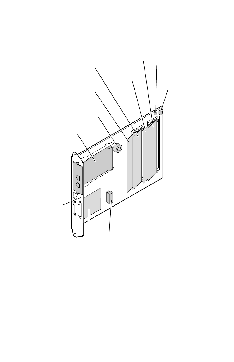
The image processor board
Phaser 740
PostScript code
ROM DIMM
Image
processor
board
Font ROM
DIMM
Network
Card
CPU
RAM
DIMM 2
RAM
DIMM 1
NV
RAM
Boot
ROM
SCSI
riser
board
Features of the image processor board
Real
Time
clock
3102-41
Service Guide
13
Page 26
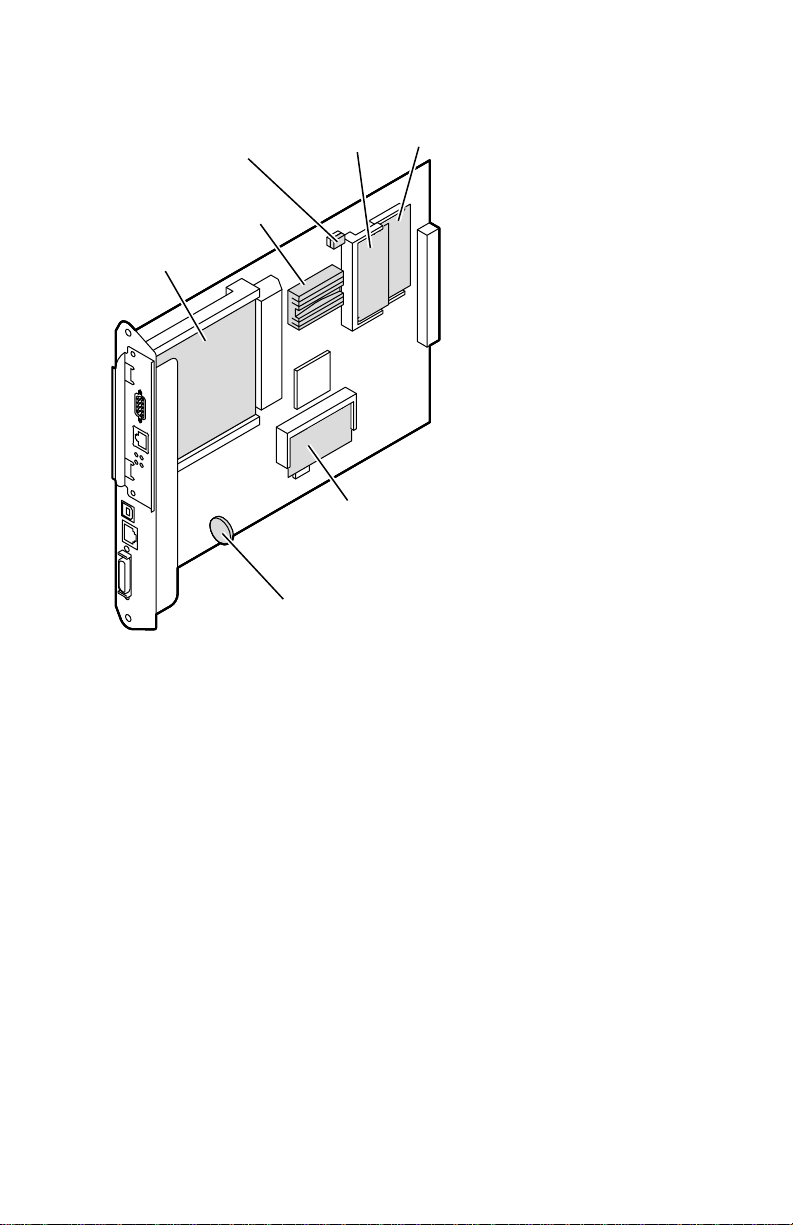
Phaser 750
RAM
module 2
Network
card or
NVRAM
CPU
hard disk
drive
Battery
(not replaceable)
Features of the image processor board
RAM
module 1
PostScript ROM DIMM
(updates standard PostScript
ROM soldered to board)
3102-43
14
Phaser 740 and 750 Color Printers
Page 27

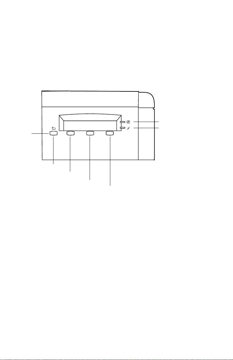
Front panel
These front panel features are found on the printer:
■
A two-line, 24-character LCD and two LEDs
■
Four push buttons
LCD
The LCD serves two purposes: displaying current image processor and print
engine status information and displaying an interactive menu. Status information
includes image processor status such as
Print engine status includes messages such as
. The interactive menu can only be entered while the print engine and image
Toner
processor are idle. The interactive menu allows the user to review and change certain
NVRAM, I/O ports and peripheral parameters.
Ready, Receiving data
Out of paper, Paper Jam
and
Printing
, and
Out of
.
Buttons
in the interactive menu. The functions of Buttons 2, 3 and 4 are defined by the
particular menu or function being displayed on the LCD display. The bottom row of
the LCD labels the current function of each button.
In addition, pressing the buttons as you turn on the printer enables certain diagnostic
modes:
The topic, “Resetting NVRAM” on page 91 explains how to use the front panel
buttons to reset the printer’s NVRAM to its factory default values.
Button 1, the left-most button labeled the Exit key, cancels an operation while
■
Pressing and holding Button 1, as you turn on the printer, skips power-up
diagnostics (except for a brief kernel test) and proceeds to PostScript
startup.
■
Pressing and holding Button 3, as you turn on the printer, executes
interactive service tests. Refer to “Phaser 740 service tests” on page 77.
Service Guide
15
Page 28
LEDs
The
Power
LED indicates the printer has +5 VDC available for its logic control
boards.
Error
The
■
■
■
LED has three meanings:
Off
indicates that no errors have been detected.
On
indicates a warning to the user. An explanatory message, such as
, is displayed on the LCD.
Toner
Blinking
indicates an error has been detected. An error message, such as,
Paper Jam at Output
Exit
Button 1
Low
, is displayed on the LCD.
Power
Error
Button 2
Button 3
Button 4
3102-30
The front panel
16
Phaser 740 and 750 Color Printers
Page 29

Rear panel
The rear panel of the printer features the host interface connectors:
■
Bi-directional parallel (high-density connector). For the Phaser 750, the
parallel port can be used to connect to a qualified optical scanner.
■
Phaser 740 printer: Twisted Pair10baseT Ethernet connector.
Phaser 750 printer: Twisted Pair10/100baseT Ethernet connector.
blinks
RX indicator (green);
LED is
a problem (probably hardware) has occurred at the network hub.
■
Phaser 740 printer only: SCSI high-density connector for connecting an
external hard disk drive or optical scanner only). The Phaser 750 printer
has no SCSI support.
■
Phaser 750 printer only: USB Type A connector for connecting to a USBcompatible host.
With the addition of the appropriate network card, the printer can feature either of
these groups of connectors:
■
Phaser 740 printer only: ThinNet (100base2) and Twisted Pair (100baseT)
Ethernet connectors. RX indicator (green);
receiving data. The LED is
LED is
network hub.
■
Phaser 740 printer only: LocalTalk connector.
off steady
on steady
while no data is being received. If the LED is on
, a problem (probably hardware) has occurred at the
while the network card is receiving data. The
steady
, then
blinks
while the network card is
off steady
while no data is being received. If the
■
Unshielded Twisted Pair (10baseT) and shielded Twisted Pair (DB-9) Token
Ring connectors. The Token Ring card installed disables the built-in
Ethernet port.
Test print button
In the center of the rear cabinet panel is the test print button. Pressing this button
while the printer is idle causes the print engine to print a built-in test print. The print
consists of a field of thin horizontal lines. The print is made independently of the
image processor board. Hold in the test button for at least 4 seconds before releasing,
or until you hear the print process begin. The print demonstrates that the print engine
can print (independently of the image processor); it has no use for determining print
quality.
Note Phaser 740 printer: The Test Print button will not make a test print if
the auto-duplex unit is installed since the Test Print function defaults
to the upper tray.
Service Guide
17
Page 30

Network card LEDs
The Ethernet port has two LED indicators. The LEDs are also found on the Ethernet
network card used by the Phaser 740 printer:
■ TX indicator (yellow); blinks while data is transmitted to the host. The LED
is off while no data is being sent.
■ T wisted Pair (100baseT) . RX indicator (green); blinks while the network car d
is receiving data. The LED is on steady while no data is being received. If the
LED is off steady, then a problem (probably hardware) has occurred at the
network hub.
ThinNet (100base2). RX indicator (green); blinks while the network card is
receiving data. The LED is off steady while no data is being received. If the
LED is on steady, then a problem (probably hardware) has occurred at the
network hub.
■ TP Link. On steady indicates good circuit to nearest port; off indicates no
circuit.
■ 100 MBS. Ethernet speed is 100 MBS when lit.
Note Do not use both Ethernet connectors at the same time. With a
Ethernet network card or Token Ring network card installed, the builtin Ethernet port is disabled.
The Token Ring network card has two LED indicators:
■ Connection (yellow); off when the printer is not inserted into the Token
Ring, blinks while the printer is attempting to insert itself into the Token
Ring, on when the printer is properly inserted in the ring.
■ Ring Speed (green); off when the card is set for 4 megabits-per-second
(MBPS), on when the card is set for 16 MBPS.
■ When both LEDs blink, a network card failure has occurred.
18 Phaser 740 and 750 Color Printers
Page 31

The printer also support an internal IDE hard drive in place a network card as a part
Ethernet Card
RX
TP
LINK
10/100Base-TX
PhaserShare
Series B
TM
TX
100
Mbs
LocalTalk Card
Series B
TX
RX
PhaserShare
TM
Token Ring Card
STP
PhaserShare
Series B
TM
of a factory installed option.
Slot for network card or IDE hard drive
10baseT Ethernet
10/100baseT
Ethernet card
SCSI
Parallel
The Phaser 740 rear panel
Slot for
network
card or IDE
drive
USB
10/100baseT
Ethernet
Parallel
10Base2
LocalTalk®
LocalTalk
card
Token Ring Card
PhaserShare
Series B
TM
STP
UTP
Mbs
INS
16
TX
RX
Token Ring
card
UTP
Mbs
INS
16
TX
RX
Token Ring
card
IDE Internal
Hard Drive
IDE Internal
Hard Drive
3102-05
The Phaser 750 rear panel
3102-42
Service Guide 19
Page 32

Health LED (Phaser 740 only)
A health LED indicates the status of the image processor board. The health LED is
mounted on the image processor board. Once the PostScript code is loaded into
memory and the image processor is initialized and running, the image processor
blinks the LED at a one-second rate.
■ Blinking (at a steady rate): The printer is operating normally. The LED
blinks irregularly during power-up self-diagnostics.
If a soft error occurs, the image processor board operates, but at a reduced
capacity. Soft failures include failure of expansion memory DIMMs or any
of the interface ports. When a soft error occurs, the printer automatically
prints a startup page listing the error.
■ On or Off: A hard error condition has occurred that would keep the image
processor board from operating.
Media tray type sensing
The combinations of the three tray sensors “tell” the print engine what type of tray is
installed. The tray sensors are located on the left-side interior of the paper tray slot.
Sensor actuators are attached to the bottom end of the tray to close the appropriate
sensor. There are six tray types:
■ Letter (A-size) paper
■ Letter (A-size) transparency film
■ Metric Letter (A4-size) paper
■ Metric Letter (A4-size) transparency film
■ Legal-size paper
■ Auto-duplex unit
Tray switch sensor combinations
Left switch Middle switch Right switch Tray type
Closed Open Open Letter (A-size) paper
Closed Closed Open Letter (A-size) transparency film
Open Open Closed Metric Letter (A4-size) paper
Open Closed Closed Metric Letter (A4-size) transparency
Open Closed Open Legal size paper
Closed Open Closed Auto-duplex unit
film
20 Phaser 740 and 750 Color Printers
Page 33
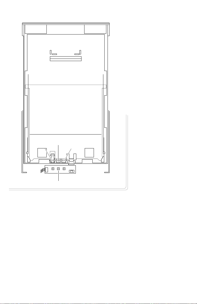
Sensor actuators
Middle
Left
Right
Tray sensors
Tray switch sensors and actuators
3102-31
Service Guide 21
Page 34

Difference between Phaser 740 and 750
Summary of differences between Phaser 740 and Phaser 750
Phaser 750 unique part Details
Main board The main board is based on a faster 603E processor running
RAM modules The Phaser 750 printer uses100 Mhz, laptop computer-style
10/100baseT Ethernet Built-in, autoswitching 10/100baseT Ethernet port available on
New Enhanced print quality The Phaser 750 features a 4 page-per-minute, 1200 x 600 dpi
Intelligent Ready mode Built-in Intelligent Ready software tracks usage patterns and
Euro currency symbol Euro currency symbol added to the internal PostScript fonts.
Embedded Pages Numerous built-in printable Help pages
Scanner support Support for approved scanners as a optical copier through the
No font DIMM All f onts are a vailable in the PostScript ROMs soldered on the
Paper feeder The Phaser 750 printer’s paper feeder, which is customer
New supported media The Phaser 750 printer support Executive-size paper
Front panel The Phaser 750 printer features, new, easier-to-navigate
at 200 MHz. It features a new rear panel with
built-in10/100BaseT and no SCSI port. The large Dallas
NVRAM chip is no longer used. Also, the Phaser 750 IP
board has no removable Boot ROM chip. A battery on the
main board will support the real-time clock (10 year life). The
printer supports up to 256 Mbytes of RAM. Only a Token Ring
Card and an IDE Internal Hard Drive are available.
RAM modules in SODIMM connectors
all Phaser 750 printer models
Enhanced print mode as its default mode.
places the printer in Standby mode during periods of non-use
and wakes-up the printer prior to a use period.
parallel port.
main board or in the snap-in PostScript ROM module which
override the built-in ROMs. The Kanji font is available on a
PostScript DIMM. Other Asian fonts are only available on an
optional internal hard drive.
replaceable, features quic k-release tabs to facilitate removing
the paper feeder. It also features a transparency sensor. The
paper feeder is not reverse compatible to the Phaser 740
printer.
(7.25 x 10.5 in.) from the Multi-Purpose Tray.
menus.
22 Phaser 740 and 750 Color Printers
Page 35

Specifications
Physical dimensions
Dimensions Specification
Height: 46.3 cm (18.2 in.) With Lower Tray Assembly: 68.6 cm (27 in.)
Width: 50.73 cm (20 in.) With output tray: 78.2 cm (30.8 in.)
Depth: 49.2 cm (19.4 in.)
Weight: Approximately 47.5 kgs (104.6 lbs.) with consumables installed.
Printer clearances
Clearances Specification
Top: 7.6 cm (3 in.)
Left: 7.6 cm (3 in.)
Right: 10.2 cm (4 in.) for handling the paper tray
Front: Unlimited for removal of consumables
Rear: 15.3 cm (6 in.) for connecting computer cable and power cord
Bottom: No obstruction under printer that could block its cooling vents.
Mounting surface
flatness:
Approximately 31.9 kgs (70.2 lbs.) without Lower Tray Assembly.
Within 2 degrees of horizontal with all four feet in contact with the
table surface.
Service Guide 23
Page 36

Functional specifications
Characteristic Specification
Printing process Electro-photographic, four color (CMYK) transfer printing
Color medium F our toner cartridges each contain one of four colors: cy an, magenta,
Addressability Standard, Fast Color and Presentation mode: 600 x 600
Printing speed
(A, A4, Legal paper)
Minimum printing
margins
Usable paper Tray: A-size (letter), A4-size (Metric letter), Legal premium Bond
yellow or black. The toner is a nonmagnetic, monocomponent
contact medium.
dots-per-inch text and graphics
Enhanced mode: 1200 x 600 dpi test and graphics
Premium mode: 1200 x 1200 dpi text and graphics
Time from paper-load to paper-eject for continuous A, A4 printing:
Four-color 4 ppm at 600 x 600 dpi (Phaser 740)
paper: 4 ppm at 1200 x 600 (Phaser 750)
Monochrome: 16 ppm at 600 dpi
Time from paper-load to paper-eject for continuous Legal printing:
Four-color 2 ppm at 600 dpi
paper: 1 ppm at 1200 dpi
Monochrome: 8 ppm at 600 dpi
Four-color transparency: 2 ppm
Fast color, three-color
(CMY): 5.3 ppm at 600 dpi
Print times do not include image processing time, which can vary
depending on image complexity.
A-size: Left and right 4 mm (0.15 in.), Top 5 mm (0.2 in.),
Bottom 5 mm (0.2 in)
A4-size: All sides, 5 mm (0.2 in.)
Legal-size: Left and right 4 mm (0.15 in.), Top 5 mm (0.2 in.),
Bottom 5 mm (0.2 in)
laser printer or copier paper
Tray feed paper weight: 60 to 90 g/m
2 ppm at 1200 x 1200 dpi
8 ppm at 1200 dpi
4 ppm at 1200 dpi
2
(16 to 24 lb.)
Multi-purpose tray: 89 x 254 to 216 x 356 mm
(3.6 x 10 to 8.5 x 14 in.)
Executive-size paper (7.25 x 10.5 in.)
#10 Envelope of a good quality.
Tektronix-brand Glossy Coated paper
Tektronix-brand Label media
Tektronix-brand Cover Stock paper
Tektronix-brand transparency film
Only Tektronix-brand A- and A4-size transparency film is supported.
Multi-purpose tray paper weight: Cover Stock up to 163 g/m2 (60 lb)
Index Stock up to 163 g/m2 (90 lb)
Two-sided printing: 75 to 90 g/m2 (20 to 24 lb)
Paper tray capacity 250 sheets using 20-lb. paper. 100 sheets of transparency film from
transparency tray. The optional Lower Tra y Assemb ly also uses tr ays
with the same capacity.
24 Phaser 740 and 750 Color Printers
Page 37

Electrical specifications
Characteristic Specification
Primary line voltages 90 to 132 VAC (115 VAC or 100 VAC nominal);
Primary voltage frequency
range
Power consumption 130 watts (fuser off), 850 watts (fuser on) during Ready state,
Primary voltage fusing 110 VAC configuration – 8 and 10 amp
Secondary DC voltages Image processor:
RF emissions Both 110 and 220 VAC-configured instruments pass these
198 to 264 VAC (220 VAC nominal)
50 to 60 Hz
950 watts during warm-up, 208 watts during printing,
45 watts during Energy Star state
220 VA C configuration – 4 and 5 amp
+ 5 VDC ± 0.25 (1A minimum, 6 A maximum)
Print engine:
+ 5V ± 0.25 (2.2 A max)
+ 24V ± 0.25 (3.0 A max)
standards: FCC Part 15 Class B
VDE Class B
EN60555-2 Class A
VCCI (CISPR 22) Class B
Environmental specifications
Characteristic Specification
o
Best print quality
obtained
Temperature
Operating
Non-operating
Storage
Humidity
Operating
Non-operating
Altitude
Operating
Non-operating
Vibration/shock
Operating
Non-Operating (vibration)
Non-operating (shock)
Acoustic Noise (operating) Average sound level (LEQ) is less than 53 dbA. Peak noise in
With in 15.5
15.5o to 32.5o C (60oto 91oF)
o
to 40o C (32o to 104o F)
0
-0o to 40o C (32 to 104o F)
Media should be acclimated 24 hours before using in the printer.
10 to 80% relative humidity, non-condensing
10 to 90% relative humidity, non-condensing
Media should be acclimated 24 hours before using in the printer.
0 to 2500 m (8,000 ft.) at 25
0 to 15000 m (50,000 ft.)
May drop any side or corner 50 mm (2 in.) without impairment of
subsequent operation.
On five mutually perpendicular axes: 0.5 g, 25-minute sweep, 5
to 200 to 5 Hz, 100 to 200 sec./sweep cycle. No resonant
frequencies below 50 Hz.
15 g, trapezoidal flared pulse, 20 msec each axis.
standby mode is 47 dbA.
to 25.5oC (60o to 78oF) and 30 to 65% RH
o
C
Service Guide 25
Page 38

Regulatory specifications
The printer is a recognized component in conformance with the following regulatory
standards:
■ The packaged product meets ASTM D4169-86 and ASTM D4728-87
Transportation Standards.
■ Listed UL 1950 Information Processing and Business Equipment.
■ Certified CSA C22.2 No. 950 Safety of Information Technology Equipment,
Including Electrical Business Equipment.
■ GS licensed IEC 950 (1991) Second Edition; EN60950 Information
Processing and Business Equipment.
■ EN50022 (CISPR 22) Class B
EN61000-3-2
EN61000-3-3
VCCI (CISPR 22) Class B
■ FCC Class B (for 115 VAC equipment) pursuant to Sub-part J of Part 15.
ICES 03 Class B
26 Phaser 740 and 750 Color Printers
Page 39

Error Codes and Messages
Error messages
Generally, the top line of the two-line front panel display indicates the printer’s status,
such as
function of the three buttons located immediately below the LCD.
The front panel also displays error codes when it encounters certain system failures.
These error codes are discussed in the next topic. When an error code first occurs,
cycle power on the printer to see if the error re-occurs.
Ready, Printing, Busy, or Stopped
Print engine error codes
The following table list the engine failure codes that may be displayed on the printer’s
front panel during normal printer operation.
Print engine service error codes
Error code Meaning of error code and what to do about it
. The bottom line indicates the
1, 2, 3, 4
05
10
Black, Cyan, Magenta, Yellow
movement error.
1.
Push the indicated toner cartridge toward the imaging unit.
Does it require more force to push that cartridge than the other
toner cartridges?
2.
Inspect the wiring harness leading from the toner cartridge
selector/eject unit to CN6 of the engine control board.
3.
Check the cam motors for proper operation toner cartridge
selector/eject.
4.
Inspect the cam motor drive gears in the toner cartridge
selector/eject.
5.
Check the cam motor flags and sensors toner cartridge
selector/eject.
6.
Replace the toner cartridge selector unit.
7.
Replace the indicated toner cartridge.
Toner cartridge/fuser fan error.
1.
Is +24 VDC being supplied to the fan from the engine control
board’s CN24 pins 1 and 2? If it is, replace the fan. If not,
replace the engine control board.
Laser scanner motor unlocked.
1.
Inspect the wiring harnesses leading to the laser scanner.
2.
Replace the laser motor drive board.
3.
Replace the laser scanner.
4.
Replace the engine control board.
5.
Replace the power supply.
(respectively)
toner cartridge
Service Guide
27
Page 40

Print engine service error codes
Error code Meaning of error code and what to do about it
12
13
L-sync over time
1.
Inspect the wiring harnesses leading from the laser driver board
to CN4. CN7, CN8 and CN 29 of the engine control board.
2.
Replace the laser motor drive board.
3.
Replace the laser scanner.
4.
Replace the engine control board.
L-sync under time.
1.
Cycle printer power and try printing again.
2.
Replace the laser motor drive board.
3.
Replace the laser scanner.
4.
Replace the engine control board.t
.
28
Phaser 740 and 750 Color Printers
Page 41

Print engine service error codes
Error code Meaning of error code and what to do about it
20
High voltage error.
Main charge grid charger
1.
Ensure that the imaging unit is properly installed and locked in
place.
2.
Ensure the main charge grid is properly installed. Ensure the
main charge grid is clean with no foreign matter in the area.
Also ensure the wire and grid plate are in good condition.
3.
Inspect the wiring leading from the high voltage board to the
main charge grid.
4.
Replace the main charge grid if necessary.
5.
Replace the imaging unit.
6.
Replace the high-voltage board.
First bias transfer roller
1.
Ensure that the imaging unit is properly installed and locked in
place.
2.
Inspect the wiring leading from the high voltage board to the
imaging unit.
3.
Replace the imaging unit.
4.
Replace the high-voltage board.
Second bias transfer roller
1.
Ensure that the paper feeder is properly installed and locked in
place.
2.
Ensure the transfer roller is properly installed. Ensure the bias
roller makes good contact with its electrical contacts.
3.
Inspect the wiring leading from the paper feeder to CN20 of the
engine control board.
4.
Inspect the wiring leading from the high voltage board to the
second bias transfer roller.
5.
Replace the high-voltage board.
Toner cartridge bias
1.
Ensure that each toner cartridge makes good electrical contact
with its high voltage bias terminals.
2.
Inspect the wiring leading from the high voltage board to the
toner cartridge bias terminals.
3.
Replace the toner cartridge if a single cartridge is exhibiting
trouble.
4.
Replace the high-voltage board.
5.
Too much conductive grease on the high-voltage contacts of a
toner cartridge developer roller has migrated down and shorted
to the chassis. Conductive grease should be used very
sparingly.
Service Guide
29
Page 42

Print engine service error codes
Error code Meaning of error code and what to do about it
21
22
30
Photoconductive belt out of sync with accumulator belt.
1.
Ensure that the imaging unit is properly installed and lock in
place.
2.
Inspect and clean the transparent plastic cover over the
accumulator belt position sensor.
3.
Inspect the wiring harness leading from the accumulator belt
position sensor to CN13 of the engine control board.
4.
Replace the imaging unit.
5.
Replace the accumulator belt position sensor.
6.
Replace the engine control board.
Positioning error of the photoconductive belt.
1.
Ensure that the imaging unit is properly installed and locked in
place.
2.
Ensure the tension lever of the imaging unit is set in the loc ked
position.
3.
Inspect the wiring harnesses leading in and out of the charger
sensor board.
4.
Replace the imaging unit.
5.
Replace the engine control board.
Accumulator belt out of position.
1.
Is the imaging unit at the end of its life?
2.
Is there toner on the accumulator belt cleaning blade holder?
(The holder is located on the imaging unit, along the bottom of
the green OPC belt.)
3.
Check to see if any toner cartridges are leaking toner.
4.
Ensure that the imaging unit is properly installed and locked in
place.
5.
Inspect and clean the transparent plastic cover over the
accumulator belt position sensor. This sensor is located on the
interior of the back wall of the chassis.
6.
Inspect the wiring harnesses leading in and out of the charger
sensor board.
7.
Replace the imaging unit.
8.
Replace the engine control board.
30
32
Accumulator belt cleaning blade movement error.
If the Error 32 is constant:
1.
Replace the imaging unit
2.
Replace the accumulator cleaner clutch shaft and the cleaning
board
3.
Replace the engine control board.
If the Error 32 is intermittent:
1.
Replace the accumulator cleaner clutch shaft and the cleaning
board
2.
Replace the imaging unit.
3.
Replace the engine control board.
Phaser 740 and 750 Color Printers
Page 43

Print engine service error codes
Error code Meaning of error code and what to do about it
33
Paper transfer roller movement error.
1.
Inspect the first drive gear (white joint gear) in the paper feeder .
Are any of its teeth broke?
2.
Ensure the second bias transfer roller is in its lower position.
3.
Check that the transfer roller sensor flag properly interrupts its
sensor.
4.
Does the transfer roller clutch and stop plate operate correctly?
5.
Inspect the wiring harness leading from the paper feeder to
CN20 of the engine control board.
6.
Replace the paper feeder.
7.
Replace the engine control board.
34
41
42
43 Fuser temperature rising too slow error.
Fuser roll exhausted error.
off end of the roll.
1.
Replace the fuser roll with new assembly and cycle power on
printer (at least 3 seconds off)
2.
Replace the fuser.
Fuser high temperature error.
1.
Replace the fuser.
2.
Inspect the wiring harness leading from the fuser to CN25 of the
engine control board.
3.
Replace the engine control board.
4.
Replace the power supply.
Fuser thermistor open.
1.
Ensure the fuser is properly installed and firmly seated in place.
2.
Replace the fuser.
3.
Inspect the wiring harness leading from the fuser to CN25 of the
engine control board.
4. Replace the engine control board.
1. Remove and reinstall the fuser. Insert it smoothly and solidly,
with force, into place. Secure it with its thumbscrew.
2. Ensure the fuser is the correct type for the printer a 220 volt
fuser installed in a 110 volt printer produces an Error 43.
3. Inspect the wiring harness leading from the fuser to CN25 of the
engine control board.
4. Replace the engine control board.
5. Replace the fuser.
6. Replace the power supply and the fuser (Phaser 740 only).
Oil web has gone or is about to go
50 Power supply fan error.
1. Is +24 VDC being supplied to the fan from the control board
connector CN30 pins 1 and 2? If it is, replace the fan. If not,
replace the power supply.
Service Guide
31
Page 44

Print engine service error codes
Error code Meaning of error code and what to do about it
51 Filter fan error.
1. Is +24 VDC being supplied to the fan from the engine control
board’s CN9 pins 1 and 2? If it is, replace the fan. If not,
replace the engine control board.
52 Auto-duplex unit fan error.
1. Replace the tray sensor board.
2. Is +24 VDC being supplied to the fan from the engine control
board thru the duplex unit’s interconnect connector and wiring
harness during duplex printing? If it is, replace the auto-duplex
unit. If not, replace the engine control board.
53 Transparency sensor error
1. Clear media jam
2. Replace paper feed unit.
60 Multi-purpose tray pick-up roller motor error
1. Is the tray ov er-filled. Too much media will overload the motor.
2. Is the multi-purpose tray motor properly connected to the paper
feeder connector CN608. Inspect its wiring harness.
3. Inspect the wiring harness leading from the paper feed motor to
connector CN20 of the engine control board.
4. Replace the paper feeder.
5. Replace the engine control board.
61 Toner cartridge (sleeve) drive motor lost sync.
1. Are the toner cartridges properly installed in position?
2. Does each toner cartridges developer roller rotate when driven
by the motor? If not replace the toner cartridge.
3. Does the toner cartridge motor rotate? Check the toner
cartridge motor’s wiring harness to the engine control board at
CN26. If the wiring checks out, replace the toner cartridge
motor.
4. Check the toner cartridge drive gears.
5. Replace the engine control board.
62 Paper feed motor lost sync.
1. Does the paper feed motor run and generate torque?
2. Does the gear train of the paper feeder rotate properly?
3. Inspect the fuser. Did the fuser roll wrap itself around the fuser’ s
hot roller?
4. Does the gear train of the fuser rotate properly?
5. Does the gear train of the paper eject rollers rotate properly?
6. Inspect the wiring harness leading from the paper feed motor to
connector CN20 of the engine control board.
7. Replace the paper feed motor.
8. Replace the engine control board.
32 Phaser 740 and 750 Color Printers
Page 45

Print engine service error codes
Error code Meaning of error code and what to do about it
63 Main motor lost sync.
1. Is the imaging unit properly installed and locked in position?
2. Do the photoconductive and accumulator belts rotate when
driven by the main motor? Manually turn the main drive gears
to rotate the belts of the imaging unit. If the gear is difficult to
turn, replace the imaging unit.
3. Inspect the drive gear for missing teeth.
4. Does the main motor rotate? Check the main motors wiring
harness to the engine control board at CN15. If the wiring
checks out, replace the main motor.
5. Replace the engine control board.
64 Lower Tray Assembly error.
1. Is the printer correctly installed on top of the lower tray
assembly?
2. Ensure that the Lower T ray Assemb ly is the correct model for the
printer. Lower Tray Assemblies for earlier model printers, such
as the Phaser 560, will not work with the Phaser 740.
70 Program ROM Checksum error.
1. Replace the engine control board.
2. Replace the engine board NVRAM.
71 Program SRAM Checksum error.
1. Replace the engine control board.
2. Replace the engine board NVRAM.
72 EEPROM Checksum error (ECU).
1. Replace the engine control board.
2. Replace the engine board NVRAM.
73 EEPROM Checksum error (imaging Unit).
1. Replace the imaging unit.
2. Replace the engine control board.
3. Replace the engine board NVRAM.
74 EEPROM Checksum error (fuser).
1. Replace the fuser.
2. Replace the engine control board.
3. Replace the engine board NVRAM.
80 VSYNC time-out.
1. Check connection between the image processor board and the
engine control board.
2. Replace the engine control board.
3. Replace the image process board.
81 Power missing error. Engine control board not powered.
1. Check wiring harness CN25 to the engine control board.
Service Guide 33
Page 46

Print engine service error codes
Error code Meaning of error code and what to do about it
82 Serial time-out error.
1. Check the connection between the image processor board and
the engine control board.
2. Replace the image process board.
3. Replace the engine control board.
83 Command error. The image processor sent bad data to the
84 Parity error.
engine control board.
1. Make sure the toner cartridges are installed, then cycle printer
power.
2. Reset the image processor NVRAM.
3. Check the connection between the image processor board and
the engine control board.
4. Replace the image process board.
5. Replace the engine control board.
1. Reset the image processor NVRAM.
2. Check the connection between the image processor board and
the engine control board.
3. Replace the image process board.
4. Replace the engine control board.
34 Phaser 740 and 750 Color Printers
Page 47

Normal power-up self-tests
This test requires no paper or customer interaction. If a problem is encountered with
the image processor's expansion memory or other options, then the information is
printed on the printer's startup page. Normal power-up tests take slightly longer
than one minute to complete.
Any failure not allowing the printer to print the start page are displayed on the
printer’s front panel with a two-digit hex code indicating what the error is. A two
digit hex code with the suffix “p” indicates the failure occurred during normal powerup self test.
Normal power up error codes
Code Power-up test Corrective action
10p Image Processor CPU Interrupt 1. Ensure that correct RAM
11p Instruction ROM Checksum
13p NVRAM Acknowledge
1bp PROM Data
1cp Font ROM Checksum
21p Write/Read Centronics
25p SCSI Interrupt
26p W/R SCSI Register
28p W/R LCA Registers
29p W/R CDU Register
2bp CDU Data Compression
2cp CDU Data Decompression
2ap DMA Address Test
2fp Network Card
1dp DRAM DIMM Configuration
31p Base DRAM Address Paths
32p Expansion DRAM Data Paths
36p DIMM1 Data Paths
DIMMs, Code ROM SIMM,
SCSI card and network
card are installed
2. Reset the NVRAM
3. Replace the Code ROM
SIMM
4. Replace the RAM DIMMs
5. Replace the image
processor board
6. Replace the font SIMM (if
installed on Phaser 740)
7. Replace the image
processor to engine board
cable
8. Replace the engine control
board
37p DIMM1 Address Paths
3ap DIMM2 Data Paths
3bp DIMM2 Address Paths
47p Engine Control Board Status
Service Guide 35
Page 48

36 Phaser 740 and 750 Color Printers
Page 49

Troubleshooting
This topic discusses troubleshooting the printer. Troubleshooting is discussed with
two approaches:
■
A step-by-step verification procedure that systematically confirms that
particular components of the printer are properly functioning until a
problem is found.
■
A symptom/cause scheme that lists particular printer failures and error
codes and their possible causes.
System power-up sequence
The following lists the chain of events that occur when you turn on the printer. Follow
this list as one means of determining if the printer is operating correctly.
When the power switch is turned on, these events occur:
■
The engine control board checks its RAM.
■
All the engine fans are turned on to ensure they work properly.
■
The fuser heater (a halogen lamp) is activated to heat up the heated roller.
■
The position of each toner cartridge is checked to ensure they are in their
parked positions.
■
The print engine checks to see that the imaging unit and the paper feeder are
installed.
■
The engine motors are rotated to ensure that their rotation sensors are
detected.
■
A check is made to determine if any paper is jammed in the printer.
■
The print engine checks the level of toner in each toner cartridge.
■
After the fuser reaches its idle temperature the printer is placed on line in its
READY state.
The print engine is initialized. If the startup page feature has not been disabled and no
error occurred with the printer, the printer prints a startup page.
Service Guide
37
Page 50

Print engine troubleshooting
This topic is a step-by-step procedure for systematically verifying particular aspects of
the printer's operation. Following this procedure should lead to the cause of a
printer's failure.
Testing the print engine
1.
If the printer does not power up, or does not initialize, or the printer initializes
but the motors do not run properly, go to the later topic, “Verifying power
supply operation” on page 39.
2.
Observe that the
to the later topic “Verifying power supply operation” on page 39.
3.
Phaser 740 printer only: V erify that the image pr ocessor’s health LED is flashing.
The health LED is viewable through the grill behind the manual feed tray (when
the tray is lowered).
4.
Press and hold the test button for 4 seconds (on the rear of the printer in the
center of the rear cabinet panel). The print engine responds by making a
parallel line test print.
If the printer prints a test print, then the printer's print engine is working correctly.
Proceed with the next topic, “Verifying printer operation by using its self-test print”
on page 39.
If the printer does not make the test print, then a problem exists with the printer.
Proceed with the topic, “Verifying power supply operation” on page 39.
Ready
message is displayed on the front panel. If it is not, go
38
Phaser 740 and 750 Color Printers
Page 51

Verifying printer operation by using its self-test print
1.
If not already on, turn on the printer. If the printer does not power up, or does
not initialize, or the printer initializes but the motors do not run properly, go to
the next topic “Verifying power supply operation.”
2.
When the
3.
Press the scroll buttons to navigate to the Test Prints menu item. Select any test
print.
4.
Press
image processor memory.
If the printer prints a test pattern, then the print engine and image processor are
working correctly and the printer's problem resides with the network or host
interface.
Ready
message is displayed, press the
Print
to print a test prints. The printer should print a test page from the
Menu
button to enter the menu.
Verifying power supply operation
Required tools
■
#1 Phillips screwdriver
■
Volt-ohm-meter (VOM)
Verifying the power supply involves four steps:
■
Measuring the input and output voltages.
■
Checking the power supply fuse(s).
■
Checking its safety interlocks.
■
Testing for a shorted motor which would shut down the power supply or
damage the engine control board.
Measuring power supply voltages
1.
Turn off the printer and unplug it from its power outlet.
2.
AC Input:
supplied to the printer. It should measure between 87 to 128 VAC (115 VAC
nominal) or 174 to 250 VAC (220 VAC nominal).
3.
Power supply fan
check the fan’s wiring harness (CN9) to the engine control board; it should
measure 24 VDC. If the voltage is not correct, r eplace the engine control board.
Otherwise, replace the power supply fan.
With the VOM set to measur e AC voltages, measure for power being
: With the power switch on, is the main fan running? If not,
Service Guide
39
Page 52
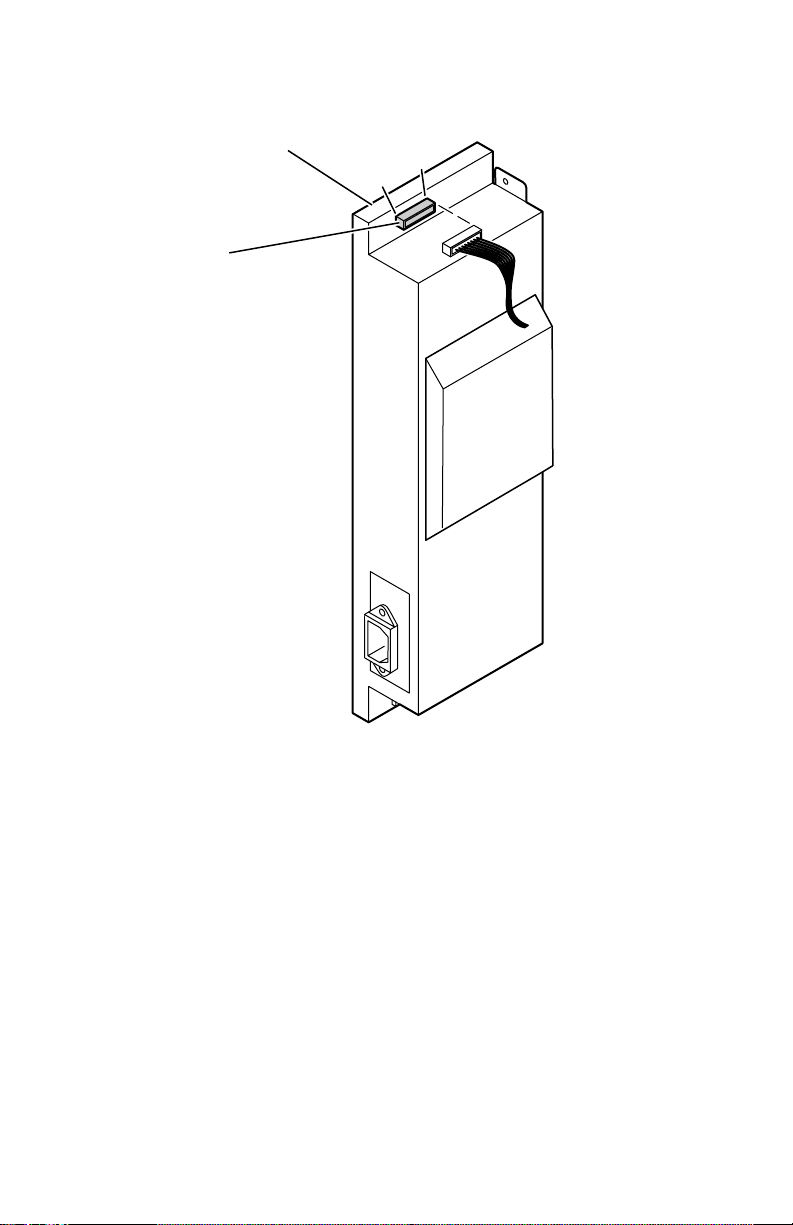
DC Output:
for +5 VDC and +24 VDC. If the voltage is not correct, replace the power supply. The
following illustration shows the test points.
With the VOM set to measure DC voltages, measure voltages at CN301
Power supply
CN 301
Pin 9 -+24 V
Pin 8 -GND
Pin 7 -GND
Pin 6 -GND
Pin 5 -+24 V
Pin 4 -+24 V
Pin 3 -GND
Pin 2 -+5 V
Pin 1 -+5 V
1
9
3102-06
Measuring the DC voltages (test points)
If DC voltages are not being output by the power supply, proceed to the next step,
“Inspecting the power supply fuses” on page 41.
If the +5 and +24 VDC voltages measure correctly, but the printer does not operate
correctly, then proceed to the topic, “Safety interlocks” on page 41.
40
Phaser 740 and 750 Color Printers
Page 53

Inspecting the power supply fuses
The 115 VAC power supply features a 8 A and a 10 A fuse. The 220 VAC power supply
fuse uses a 4 A and a 5 amp fuse.
1.
Turn off the printer.
2.
Remove the power supply.
3.
Remove the power supply cover to access the fuses.
4.
Visually, and with a VOM, check to determine that the fuse is in working order.
If the fuse is good, but the printer's power supply does not output DC voltages,
proceed to the next topic, “Testing for a shorted motor.”
Safety interlocks
The printer features four safety interlock switches:
■
Front door-opened switch.
■
Right side door-opened switch.
■
Left door-opened switch.
■
Optional Lower Tray Assembly door switch.
When any of the switches are opened, the +24 VDC supply to the motors is shut
down, as well as the high-voltage power supply.
1.
T est the functionality of the interlock using the service tests described in “Phaser
740 service tests” on page 77.
2.
Turn off the printer.
3.
With a VOM, set to measure resistance, test each switch when it is opened and
closed.
4.
Inspect each switch’s wiring harness for pinches, nicks or open connections.
If you find a switch that is defective, replace it.
If the switches work correctly and the DC voltages are correct, then the problem may
be an open or otherwise faulty motor.
Service Guide
41
Page 54

If no motors appear to be at fault, replace the engine control board.
Right side door
interlock switch
Front door
interlock
switch
Left door
switch
Optional lower
tray assembly
door switch
Door safety interlock switches
Testing for a shorted motor
1.
Remove the cabinet top and rear access panel.
2.
Refer to the topic “Wiring Diagram” on page 135 for a diagram that locates each
connector.
3.
Disconnect the motor harnesses.
4.
Turn on the printer again to see if it overloads now that the motors are
disconnected from the engine driver board.
If the motors and solenoids are functional, but the power supply still does not
function, replace it.
42
Phaser 740 and 750 Color Printers
3102-07
Page 55

Media jams and the paper path
Required tools
■
#1 Phillips screwdriver
■
VOM
Jams fall into the following four categories:
■
Media-based problems
■
Paper-picking errors
■
Printing jams
■
Paper-ejecting errors
Media-based problems
Media problems
1.
T est the paper path using the service tests described in “Phaser 740 service tests”
on page 77 or “Phaser 750 service tests” on page 80.
2.
Check that the correct type of media is being used. The customer should be
using a quality laser printer paper. The printer may have trouble picking slickfinish paper.
3.
Inspect the paper for bent, torn or folded corners.
4.
Ensure that the correct media is loaded in the paper tray.
5.
Transparency film should only be used from a transparency tray or multipurpose tray.
6.
Refer to the media specifications in the table “Functional specifications,” on
page 24.
Service Guide
43
Page 56

Multiple-sheet pick
1.
Is the paper in good condition and appropriate for a laser printer? Quality of fice
laser printer paper works best.
2.
Is the printer printing within its environmental specifications?
3.
Ensure the corners or the paper are under the tabs in the corners of the tray.
4.
Clean the pick rollers.
5.
Replace the paper tray.
The media skews passing through the paper path
1.
Make sure that the media is properly installed in the tray.
2.
Does the pick-up roller pick up evenly? Is it clean?
3.
Are the tray's side paper guides snugly adjusted against the stack of media?
The guides, while not adjustable, should be neither too loose nor too tight.
4.
Is the paper tray damaged or obstructed?
5.
Is there an obstacle blocking the paper path?
6.
Is the media excessively curled?
7.
Is the customer using an appropriate type of media – a type the printer can
handle?
8.
Ensure the corners or the paper are under the tabs in the corners of the tray.
9.
If the paper only skews when feed from the upper tray, replace the left door.
Paper tray indicates empty when it is not
The procedure for troubleshooting this problem applies to the Lower Tray Assembly
as well.
1.
Does the paper empty flag properly interrupt the paper empty sensor on the
paper feeder board? Open the left door to observe the flag in action.
2.
Test the sensor using the service tests described in “Phaser 740 service tests” on
page 77 or “Phaser 750 service tests” on page 80.
3.
Does the paper feeder, when installed, properly connect to the print engine? Is
the paper feeder’s wiring harness properly connected to the engine control
board (CN20)? (For the Lower Tray Assembly, check connector CN19). Inspect
the wiring harness for defects.
4.
Replace the paper feeder.
5.
Replace the engine control board.
44
Phaser 740 and 750 Color Printers
Page 57

No paper feeder installed
1.
Check to see if the paper feeder is properly installed in the printer and making
good electrical contact. Push it in all the way.
2.
Ensure that the wiring harness leading from the paper feeder to the engine
control board is properly installed in connector CN20. Check the wiring harness
for defects.
3.
Replace the engine control board.
No imaging unit installed
1.
Ensure that the imaging unit is properly installed and locked in place.
2.
Check the main charge grid boss on the rear of the charger to ensure it is not
broken. When the imaging unit is installed, the boss pushes a flag on the
charger sensor board. Replace the charger or imaging unit if it is broken.
3.
Test the sensor using the service tests described in “Phaser 740 service tests” on
page 77 or “Phaser 750 service tests” on page 80.
4.
Check the high-voltage terminal connectors for the imaging unit to ensure that
they are not damaged.
Service Guide
45
Page 58

Jams
Wrong media
1. Ensure the correct media type is loaded in the correct tray.
2. Test the media sensors
3. Replace the paper feeder.
Paper mis-picks at the paper tray
1. Is the paper in good condition and appropriate for a laser printer?
2. Is the printer printing within its environmental specifications?
3. Is the pick-up roller dirty? If so, clean it and try printing again. You can also
slide off the “treads” from the pick rollers and reverse them to present a fresh
pick-up roller edge to the paper.
4. Does the pick roller rotate? Mark the end of the pick roller shaft. Open the fr ont
door and defeat the door open interlock to see the shaft turn.
■ If the roller does not rotate, does the paper feed motor run? Check the
motor’s wiring harness and connection (CN20) to the engine control board.
■ Check the gear train for broken teeth and proper installation.
■ Replace the paper feed motor.
■ Replace the engine driver board.
■ If the pick roller rotates out of position with each pick, its clutch is worn.
Replace the paper feeder.
5. If the pick roller does rotate, is the pick roller correctly installed (flat side of the
cam-shaped pick rollers face down prior to picking a sheet of paper)?
■ Does the pick solenoid work properly? It must energize for the pick roller to
be engaged and rotate. If it doesn’t, replace the paper feed circuit board.
■ Replace the paper feeder.
Paper jams midway in the paper feeder
1. Ensure that the pick-up rollers are clean.
2. Check the left side door for burrs or foreign obstructions that could block the
movement of a sheet of paper.
3. Clean the intermediate rollers (pinch roller and drive roller).
4. Check the pinch intermediate roller mounted on the inside of the left door for
even spring tension at each end of the roller. The spring tension should measure
about 65 grams when the roller end is in the middle of its travel in its slot.
5. Does the pick-up roller clutch work properly?
46 Phaser 740 and 750 Color Printers
Page 59

Try printing using a different paper tray.
6.
7. Transparency film. Do not use transparency film in the lower tray of the Lower
T ray Assembly.
Paper jams at the second bias transfer roller
1. Clean the intermediate rollers.
2. Is the transfer roller correctly installed?
3. Is the transfer roller moving up for image transfer when it should?
4. Does the paper jam sensor flag properly interrupt the sensor? Check the wiring
harness of the paper jam sensor leading to CN607 of the paper feeder board.
5. Does the drive intermediate roller rotate? If not, check the gear train driving the
gears for proper installation and for broken teeth.
6. Check the left side door for burrs or foreign obstructions that could block the
movement of a sheet of paper.
7. Check the pinch intermediate roller mounted on the inside of the left door for
even spring tension at each end of the roller. The spring tension should measure
about 65 grams when the roller end is in the middle of its travel in its slot.
8. Clean the aligning rollers.
9. Do the aligning rollers rotate during a paper pick? Determine if the aligning
roller clutch operates correctly.
10. Check that the paper feeder wiring is properly installed and that the wiring
harnesses are not damaged.
11. Check the spring pressure at each end of the aligning r ollers. Lifting each end of
the roller with a tension gauge should reveal a measurement of about 1 kg (2.2
lbs).
12. Check the left side door for burrs or foreign obstructions that could block the
movement of a sheet of paper. Check for a paper scrap in the paper guide.
13. Try printing using a different paper tray.
Service Guide 47
Page 60

Fuser jams
1. Is the paper in good condition and appropriate for a laser printer?
2. Is the printer printing within its environmental specifications?
3. Is this a duplex print with heavy printing (lots of toner coverage) on the first-
printed side? Print the light-printing side first.
4. Is the heat shield plate at the entrance of the fuser loose and obstructing the
paper path?
5. Inspect the fuser’s gear train leading to the paper feed motor. Does it rotate
properly? Do any of the gears show broken teeth?
6. Does the fuser exit sensor flag properly actuate its sensor?
7. Inspect the wiring harnesses leading from the cartridge sensor/eject unit to
CN21 of the engine control board.
8. Inspect the fuser roll. If it is empty, replace the fuser roll.
9. Observe if the exit rollers rotate during the print process. If they do not, r einstall
the fuser to ensure its gear train (which also drives the exit roller) properly
connects to the paper feed motor.
10. Replace the fuser.
11. Replace the engine control board.
Eject jams
1. Is the paper in good condition and appropriate for a laser printer? Is the paper
curling?
2. Is the printer printing within its environmental specifications?
3. Is the jam caused by a heavy, stiff paper being printed in face-down mode? In
such cases, face-up mode or a lighter grade of paper should be used.
4. Is the paper excessively curved after passing through the fuser that the reverser
(eject unit) can’t flip the paper? Try flipping the paper over in the tray.
5. Clean all the eject rollers.
6. Inspect the interior of the printer reverser of the toner cartridge selector/paper
eject unit. Ensure that the metal fingers inside the reverser are not bent or
interfere with paper movement.
7. Does the paper exit sensor flag properly actuate its sensor?
8. Inspect the wiring harness leading from the cartridge sensor/eject unit to
CN308 of the engine driver board.
9. Replace the cartridge selector/eject unit.
10. Replace the engine control board.
48 Phaser 740 and 750 Color Printers
Page 61

Multi-purpose tray feed jams
1. Is the paper in good condition and appropriate for a laser printer?
2. Is the printer printing within its environmental specifications?
3. Do not overload the multi-purpose tray; otherwise jams will occur. Check the
position of the media thickness selector at the paper feeder (inside the left door).
4. Clean or replace the multi-purpose feed pick roller.
5. Is the picked media properly interrupting the aligning sensor?
6. Is the multi-purpose feed sensor empty flag properly interrupting the multi-
purpose pick sensor?
7. Check the wiring harness between the multi-purpose sensor circuit board and
the paper feeder board (connector CN607). Ensure that the wiring harness is not
damaged.
8. Check the wiring harness leading from the paper feeder to the engine control
board (connector CN20).
9. Replace the paper feeder circuit board.
10. Replace the engine control board.
Jams in the duplex unit
1. Is the duplex unit correctly installed?
2. Clean the rollers inside the auto-duplex unit.
3. Inspect the duplex unit for foreign objects such as a shard of paper.
4. Does the duplex unit’s clutch operate correctly? Refer to “Phaser 740 service
tests” on page 77 or “Phaser 750 service tests” on page 80.
5. Inspect the duplex unit’s electrical connector for damage.
6. Replace the duplex unit.
Service Guide 49
Page 62

Other problems
These problems may be indicated as errors on the front panel.
The printer continuously displays “Initializing”
The most likely cause is that the image processor has not loaded its EEPROM contents
(instructions) into RAM successfully. This is usually indicated by the health indicator
LED (heart beat) being on or off but not flashing. All print engine operation halts, and
will only become ready when the image processor has successfully booted.
1. Re-powering the printer, or perform a NVRAM reset.
2. To verify if the image processor has failed:
a. Power down the printer, and remove the back of the printer to gain
access to the ribbon cable connecting the image processor board to the
print engine control board; disconnect the ribbon cable at the control
board.
b. Power-up the printer. Wait at least 5 minutes while the print engine
initializes. If there was a problem with the image processor, it will now
not affect the print engine control board.
c. Check if the print engine is OK by pressing the print engine test print
button, you should get the parallel line test print. If not, then your
problem is most likely associated with the print engine control board,
and you will need to replace it. If, however, you get the print engine
test print, then your most likely cause is the image processor.
No toner cartridge installed message when it is
1. Ensure that the toner cartridge is correctly installed.
2. Replace the toner cartridge.
3. Replace the toner cartridge drive unit.
4. Replace the engine control board.
No fuser installed message when it is
1. Ensure that the fuser is correctly installed.
2. Check the fuser’s connection and wiring.
3. Check the wiring harness leading to the fuser power connector.
4. Replace the fuser.
5. Replace the engine control board.
50 Phaser 740 and 750 Color Printers
Page 63

No fuser roll installed message when it is
1. Ensure that the fuser roll is correctly installed.
2. Check the fuser’s connection and wiring.
3. Check the wiring harness leading to the fuser power connector.
4. Replace the fuser.
5. Replace the engine control board.
Front door open when it is closed
1. Inspect that the front door’s interlock for damage.
2. Inspect the cartridge selector/eject unit interlock mechanism for damage.
3. Inspect the front door cartridge selector/eject unit interlock mechanism. Ensure
that when the interlock is actuated by the cartridge selector/eject unit being
closed, the interlock switch, mounted on the toner cartridge drive unit, closes
(with an audible click).
4. Replace the interlock switch.
5. Replace the power supply.
6. Replace the engine control board.
Left-side door open message when it is not
The procedure for troubleshooting this problem applies to the Lower Tray Assembly
as well.
1. Is the left door open switch, located in the lower-left back corner of the printer,
properly in place?
2. Does closing the left door actuate the left door open switch?
3. Is the left door properly in place? Replace the door if it does not operate
correctly.
4. Is the left door open switch’s wiring harnesses properly connected to the engine
control board (CN3 – 24V interrupt)? In the case of the Lower Tray Assembly, is
the printer properly seated onto the Lower Tray Assembly with good electrical
connection. Try reseating the printer. Check the lower feeder’s wiring harness
to the engine control board at connector CN19.
5. Replace the left door open switch.
6. Replace the engine control board.
Service Guide 51
Page 64

High temperature error
1. Replace the power supply unit.
2. Check the fans.
3. Replace the engine control board.
Low temperature error
1. Ensure the fuser is properly installed.
2. Check the fuser’s connection and wiring.
3. Check to see if the fuser’s thermo-fuse is open. With an ohmmeter, measure the
top two pins of the fuser’s connector. For 1 10 VAC fuser you should measure 1.6
ohms. For 220 VAC fuser you should measure 5.4 ohms. If it is opened, replace
the fuser.
4. Replace the fuser.
5. Replace the power supply unit.
6. Replace the engine control board.
High voltage error
1. Replace the high voltage board.
2. Inspect the high-voltage wiring.
3. Replace the imaging unit and check the printer for proper operation.
4. Sequentially replace each toner cartridge and check the printer for proper
operation.
5. Ensure that excessive conductive grease has not migrated and shorted a high-
voltage contact to ground on the second bias transfer roller.
Thermistor open error
1. Check the connector CN27 on the engine control board.
2. Ensure a 110 volt fuser has not been installed in a 220 volt printer; it will damage
the power supply thermistor and require the power supply be replaced.
3. Replace the fuser.
4. Replace the engine control board.
52 Phaser 740 and 750 Color Printers
Page 65

Front panel cycling between READY and WARMING UP
1. Make sure that the fuser, imaging unit, and toner cartridges are well seated.
2. Invoke a test print from the Front Panel to try to get an error message to be
displayed that may be present but, is masked by the front panel cycling between
READY and WARMING UP.
3. Make sure all connectors to the circuit boards are well seated and make sure
that the screws holding the boards’s in place are tight.
Erratic printer behavior
1. Phaser 740 only: Check the amount of RAM installed in the printer . While mor e
than 192 Mbytes of RAM can be physically installed on the image processor
board, it can electrically support no more than 192 Mbytes. Unreliable printer
operation can otherwise result.
2. Perform an NVRAM reset.
Installed RAM not recognized
1. Upon power-up, the image processor checks each DIMM for information such
as data width, clock delay, number of address columns and row , r efr esh rate and
more. If the DIMM does not meets the requir ed specifications it will be ignor ed;
no error message will be reported.
Service Guide 53
Page 66
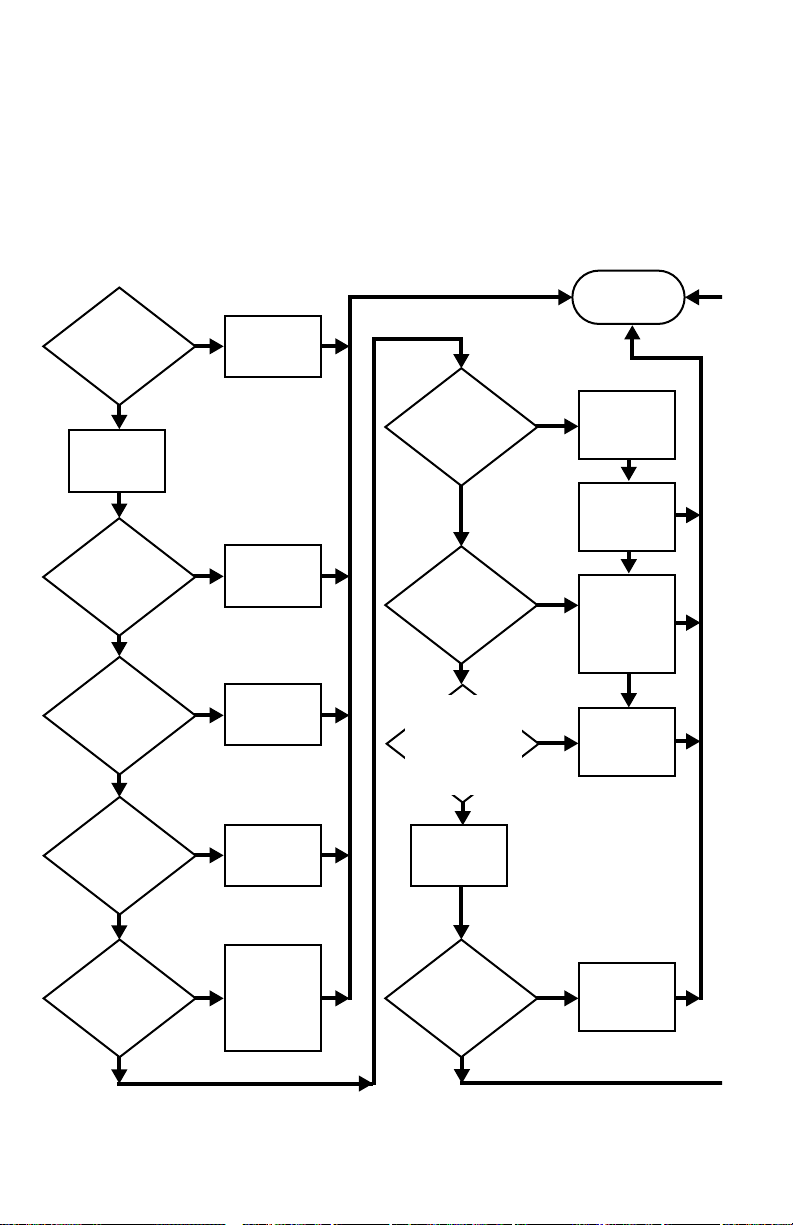
Printing and print quality problems
Required tools
■ #1 Phillips screwdriver ■ Conductive grease
■ Volt-ohm-meter (VOM) ■ Ruler
The following flow chart represent an effective, systematic means of troubleshooting
print quality. Following the chart are examples of print quality defects and probable
solutions.
Start
Does the
front panel display
a message to
replace a supply
item?
No
Print the
Diagnostic
Test Pages
(DTP)
Is the print
quality problem
on only one solid
color page?
No
Is the
customer using
a media type that
is NOT on the
supported
list?
No
Is the printed
image offsetting
or are the prints
smudged?
Yes
Yes
Yes
Yes
Replace the
indicated
supply item
Replace that
color's toner
cartridge
Try a
supported
media
Run the
Clean
for Smudges
procedure
Print quality is
acceptable.
Stop
Is the
entire image too
light or too dark?
No
Is the
environment outside
the printer's
specifications?
No
Based on
TEKSMART, is the
print quality problem
a documented printer
limitation or unsup-
portable customer
expectation?
Yes
Yes
Yes
Perform the
Calibrate for
Paper
adjustment
Perform the
Calibrate
Colors
procedure
Move the
printer to an
operating
environment
that is within
specifications
Help establish
customer
expectations
or escalate
No
Print the
Supplies
Page
No
Is the
print quality
problem repeated
more than once
on each
page?
Yes
troubleshooting
which supply
item to replace
Use the
following
images to
determine
No
Troubleshooting print quality problems
54 Phaser 740 and 750 Color Printers
Does the
imaging unit or the
fuser have less than
20% life
remaining?
No
Yes
Swap that
supply item
Page 67
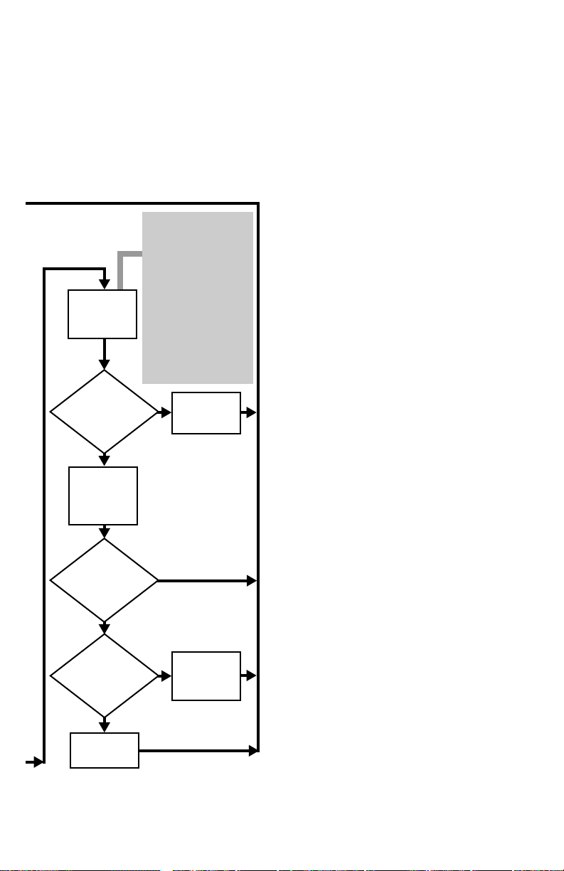
Make an
unfused
Diagnostic Test
Page print
Has the print
quality problem
disappeared on the
unfused print?
No
Reseat the
transfer kit and
make a normal
Diagnostic Test
Page print
Cut about 3 inches off the
length of a piece of paper.
Place it in the MPT and
select the MPT as the
default tray. Request a
Diagnostic Test Page. The
printer will display a jam
message. Open the left
side door; use the blue
handles to pull out the
paper feeder. Being careful
not to get toner on
yourself, carefully slide the
paper out of the printer.
Slide the paper feeder back
into the printer and close
the door.
Yes
Replace the
fuser
Is the
Diagnostic Test
Page print quality
OK?
No
Is the
print quality
problem dark streaks
down the length of
the page?
No
Replace the
imaging unit
Yes
Yes
Clean or
replace the
main charge
grid
3102-46
Service Guide 55
Page 68

Blank print
1. Press, and hold for 4 seconds, the rear panel Test Print button to determine if the
print engine will image at all. It should produce a parallel line print. If the
engine produces a good parallel line print, the print engine is good and the
image processor board is bad. If you get a blank print then the following items
may be defective. The engine test print feature only works if a paper tray is
installed in the top tray slot.
2. Replace the laser unit.
3. Replace the imaging unit.
4. Determine if the cartridge selector is pushing the toner cartridges into contact
with the photoconductive drum.
5. Replace the toner cartridge drive unit.
6. Replace the cartridge sector/eject unit.
7. Replace the engine driver board.
All-black print
1. Entire print, including margins is black. Remove and reinstall the main charge
grid.
2. Inspect the main charge grid for a broken corona wir e. Replace the main charge
grid.
3. Replace the high-voltage board
4. Margins are white, print is black. Replace the image processor board.
5. Replace the engine control board.
56 Phaser 740 and 750 Color Printers
Page 69
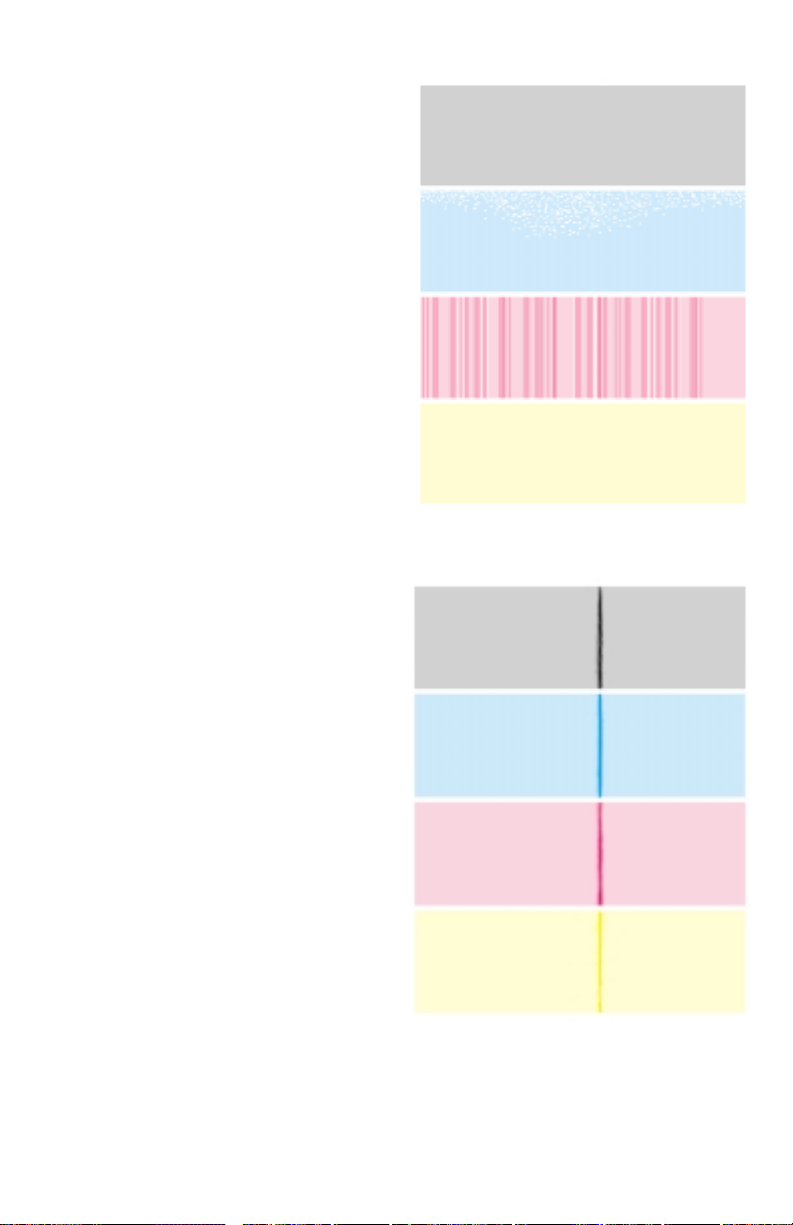
Single color mottled or with non-uniform density streaks
If a single color displays a mottled
appearance or if a single color shows
many vertical streaks of varying densities,
then that color’s toner cartridge is running
of toner. Replace the cartridge.
Dark vertical line in print, single color
If the line is of one primary color , then the
trouble can usually be traced to a defect in
the color’s toner cartridge. Too much
toner is transferred from the developer
roller to the photoconductive belt at the
defect point.
9922-93
Vertical line in print, all colors
The problem may be caused by a dirty
main charger, a defect in the fuser or a
defect in the imaging unit.
9922-78
Service Guide 57
Page 70

Vertical line or scratch in print, single color
If the scratch is of one missing primary
color, then the trouble can usually be
traced to a scratch in the developer roller
of the missing toner’s toner cartridge. No
toner is transferred from the developer
roller to the photoconductive belt at the
defect point.
Vertical line or scratch in print, all colors
The problem may be caused by
contamination on the laser window where
the laser beam exits the laser scanner and
enters the imaging unit. Since the blocked
laser beam cannot discharge the portion
of the photoconductive belt it cannot
reach, toner will not transfer to those
portions of the belt. Consequently a
blank, vertical line will appear on the
prints in all colors. Remove the imaging
unit and, with a squeeze bulb, blow any
dust or toner off of the window (located in
the “ceiling” of the cavity left in the
printer once the imaging unit is removed).
If it is in all colors then the problem may be in the imaging unit, such as a scratched
photoconductive belt. Replace the imaging unit.
9922-75
A very thin, white line could be caused by a scratched roller in the fuser which
replacing will solve. The scratch in the print may not be continuous but rather a set of
in-line vertical scratches. Inspect the fuser roller and the print. If the scratches are
about 12.1 cm (5 in.) apart and match the defects on the print, then the problem is a
scratch on the fuser roller. Replace the fuser.
Lastly, a protrusion of some kind in the paper path could be scratching the print.
58 Phaser 740 and 750 Color Printers
Page 71

Small, repeating light dot in one color in-line with each other
This can usually be traced to a dent-like
defect in the developer roller of the
toner cartridge in question. Measure the
spacing between the spots. The distance
between the repeating spots indicates
the source of the problem.
In some instances, the spots may be dark
instead of white. They may also be
shaped something other than round.
■ The dents should be 3.4 cm (1.5 in)
apart or 2.5 cm (1 in.) for 1200 dpi
printing. No toner is transferred
from the developer roller to the
photoconductive belt at the defect
point.
■ If the spots are about 12.5 cm (5 in.)
apart, then the problem is a defect
on the fuser roller. Replace the
fuser.
■ Thin horizontal lines, depending on
problem, the distance between lines
may range from 1.5 mm (1/20th
inch) between each line to 103 mm
(4 in.) between each line. The gear are “chattering” in paper feeder. Apply a
single drop of molybdenum grease (br own gr ease) to each gear and let print
action work the grease into the gears. Avoid excess grease.
■ 26.5 mm (1 in.): Toner cartridge at 1200 dpi. Replace the toner cartridge.
■ 35 mm (1.3 in.): Toner cartridge at 600 dpi. Replace the toner cartridge.
■ 76 mm (3 in.): Second bias transfer roller. Replace the transfer roller.
■ 43 mm (1.7 in.): Imaging unit drive gear train.
■ 95 mm (4 in.): Imaging unit belt roller defect. Replace the imaging unit.
■ 102 mm (4.1 in): Paper feeder drive gear broken tooth. Replace the paper
feeder drive gear.
■ 121 mm (5 in): Fuser roller defect. Replace the fuser.
9922-76
Service Guide 59
Page 72

Single light, horizontal line in all the prints
This is probably caused by a defective
photoconductive belt onto which toner
will not transfer.
1. Replace the imaging unit.
2. Replace the second bias transfer
roller. Inspect it for loose roller
contacts. Grease the end of the
roller shaft with conductive grease.
Large, random light smudges
Spots such as those illustrated are
caused by fingerprints on the
photoconductive or accumulator belt.
Often, the smudges will gradually fade
with additional printing. Alternately,
the imaging unit will have to be
replaced.
9922-78
Fingerprints can be removed by
applying some toner (any color) to the
fingerprints and rubbing lightly with a
cotton-tipped swab. Don’t remove the
toner . The printer will remove the toner
with its cleaning blade. Remember not to
expose the imaging unit to ambient light for
more than a minute.
60 Phaser 740 and 750 Color Printers
9697-50
Page 73

One or more dark vertical line in all colors
This can often be traced to a dirty
scorotron charger (main char ger) cor ona
wire. Contamination (dust or toner)
interferes with the flow of electrons
from the wire to the photoconductive
drum. Toner is then transferred to the
area of low electron charge and
consequently to the accumulator belt
and finally the print.
1. Inspect the main charger for toner
or other contamination. White
streaks are caused by a dirty grid.
Black streaks are caused by a dirty
wire. If contaminated, its charge
wire will appear fuzzy. Replace the
scorotron charger, if necessary.
1. Inspect the photoconductive belt for
damage. Replace the imaging unit
if necessary.
2. Inspect the path the laser beam
travels for foreign matter that could
block the beam from striking the
photoconductive belt.
9322-89
3. If the line is colored, one toner cartridge may not be outputting toner correctly.
Replace the missing color’s toner cartridge.
4. Inspect the second bias transfer roller for a scratch or contamination. Replace
the roller if necessary.
5. Inspect the cleaning blade. Ensure no foreign matter is stuck to it.
6. Are the fuser rollers scratched? Replace the fuser.
Service Guide 61
Page 74

Dark, irregular, vertical streaks and smears on the entire page
This is usually due to the accumulator
belt toner waste bin being filled and
spilling out on the belt. The spilled
toner is then being transferred to the
print. Most prominent in the middle of
the print and in the yellow band. A
defective cleaning blade could also
cause this. In either case, replacing the
imaging unit should fix the problem.
Alternately, replace fuser.
One primary color faded or pale OR a single color has a dark vertical streak
9697-52
This indicates a problem with a single
toner cartridge. Replacing the toner
cartridge should fix the problem.
If it does not, there may be a problem
with the toner cartridge selector/eject
unit. It may not be pushing the
cartridge quite far enough to make
proper contact with the
photoconductive belt, resulting in poor
toner transfer. Replace the toner
cartridge selector/eject unit.
Lastly, poor electro-mechanical contact
my be the problem, although this
usually shows itself as light, horizontal
streaks and lines. Replace the toner
cartridge biasing assembly.
62 Phaser 740 and 750 Color Printers
9697-53
Page 75

Light, faded, pale prints
1. The imaging unit is old or has been
exposed to too much room light.
Replace the imaging unit.
2. Is the paper in good condition and
appropriate for a laser printer?
3. Is the printer printing within its
environmental specifications? For
the Phaser 750 printer, print the
built-in Diagnostic Test Page; the
current temperature and humidity
is printed on the page.
4. Check the media type and tray type
for proper match. If printing is
weak on paper only, the printer
may be printing in transparency
mode. Does the media in the multipurpose feeder match the default
setting made using the front panel?
Check to see if paper was picked
from a transparency tray or if the
multi-purpose tray is set for
Transparency.
5. For desired paper, run the front panel routine Calibrate for Paper.
6. Check to see if the Color Calibration menu is set to print lighter.
7. The high-voltage board is not outputting sufficient voltage to the second bias
transfer roller, causing poor transfer of toner to paper. Likewise, low voltage to
the toner cartridge will cause insufficient transfer of toner to the
photoconductive belt.
9697-51
8. Inspect the high voltage connector for poor contact with the second bias transfer
roller.
9. The beam from the laser scanner is weak and is not properly exposing the
photoconductive belt. Poor laser exposure results in the negative charges
remaining on the photoconductive belt instead of being “erased” by the laser
beam, thereby retarding toner transfer from the toner cartridges. Replace the
laser scanner.
10. Inspect the path the laser beam travels for contamination.
11. Inspect the action of the cartridge selector to ensure that it is pushing the toner
cartridges into full contact with the photoconductive drum.
12. Replace the imaging unit.
13. Replace the second bias transfer roller.
14. Replace the engine control board.
Service Guide 63
Page 76

Single white spot appear in the same place on the print
This indicates a bad spot has developed
on the imaging unit’s photoconductive
belt which will not transfer toner. The
imaging unit must be replaced. If the
spot appears to migrate vertically from
print to print then the defect is on the
imaging unit’s accumulator belt. In
either case the imaging unit must be
replaced.
Contamination of one color by another
This is most noticeable on solid primary
fills. This is caused by a defective
photoconductive cleaning blade. The
blade is not scraping off all of the
untransferred toner from the previous
pass of the photoconductive belt to the
accumulator belt prior to the next
toner’s transfer to the photoconductive
belt. Replacing the imaging unit
corrects this problem.
9697-54
Rarely, a sheet of paper can become
folded and jam in the imaging unit,
smudging the image.
64 Phaser 740 and 750 Color Printers
9322-90
Page 77

Missing primary color
1. Replace the toner cartridge of the
missing color.
2. Determine if the cartridge selector
is pushing the toner cartridges into
contact with the photoconductive
drum.
3. Check the wiring harness leading
from the cartridge selector/eject
unit to CN308 of the engine control
board.
4. Replace the toner cartridge drive
unit.
5. Replace the engine driver board.
6. Phaser 750 printer only. Run the
printer calibration routine Calibrate
for Paper available from the front
panel Help/Printer Quality menu.
Mis-transfer, missing portions of toner
1. Inspect the heat roller (top roller) of
the fuser for scratches or
contamination.
9697-55
2. Ensure the media is correct for the
printer.
3. Replace the fuser.
9697-56
Service Guide 65
Page 78

Dirty background
1. Inspect the scorotron charger for toner or other contamination.
2. If excess printing in background is of one primary color, replace that color’s
toner cartridge.
3. Replace the high-voltage board.
4. Dirty background can occur if the customer prints prolonged volumes of
monochrome (single primary color) prints. Replace the toner cartridge that is
overused.
5. Check color calibration adjust values.
Stains on the back of the print
1. Replace transfer kit.
2. Empty the waste bin of the second bias transfer roller.
3. Clean the paper path of the paper feeder.
4. Inspect the fuser rollers for contamination. Replace the fuser.
5. Replace the paper feeder.
Some stains may appear on the back of Legal-size media. This is a limitation of the
print engine.
Ghosting
Ghosting with some images is unavoidable because of the color structure of the
images. If a color is used at one part of the image area and the same color is used
again at a later area, it is very possible to get ghosting of the first image into the second
image area after one revolution of the toner cartridge developer roller. This occurs
because the charge that is created from the first use of the color was not totally
extinguished. A small residual charge remains associated with the color , r esulting in a
second use of the color to be darker in the same areas as the first image. This r esults in
the first image ghosting into the second image when the same color is used.
1. A new toner cartridge exhibits less ghosting. Ghosting increase as toner
cartridges age.
Unfused or partially fused printing
1. Is the paper in good condition and appropriate for a laser printer?
2. Is the printer printing within its environmental specifications?
3. Run 10 to 20 blank sheets of paper through the printer.
4. Replace the fuser unit.
66 Phaser 740 and 750 Color Printers
Page 79

Image is skewed on the paper
1. Is the paper in good condition and appropriate for a laser printer?
2. Is the printer printing within its environmental specifications?
3. Swap the tray that the affected print originates from.
4. Ensure that the paper feeder is properly installed. Inspect its paper pick roller.
Look for obstructions in the paper path.
5. Clean the intermediate and aligning rollers.
6. Replace the paper feeder.
No printing on edge of print
1. If one primary color is missing, replace that color’s toner cartridge.
2. Check that each toner cartridge moves forward smoothly toward the imaging
unit. Also inspect the two metal pads on the ends of the toner cartridge that the
toner cartridge selector cams push against.
3. Inspect the cartridge selector/eject unit to ensure that the cams are in good
condition. Replace the cartridge selector/eject unit.
4. Replace the imaging unit.
Image is not centered on the print when it should be
1. Is the paper in good condition and appropriate for a laser printer.
2. Is the printer printing within its environmental specifications?
3. Ensure the paper feeder is properly installed.
4. Is the top and left margin adjustments correct? Refer to the service tests
discussed in the topic “Printer self-diagnostics” on page 77.
5. Clean the intermediate and aligning rollers.
6. Replace the paper feeder.
7. Replace the engine control board.
8. Replace the laser scanner.
Service Guide 67
Page 80

The print is wrinkled
1. Check for an obstruction in the paper path, particularly the paper feeder and the
fuser.
2. Is the paper in good condition and appropriate size, weight, grain and grade for
a laser printer?
3. Is the printer printing within its environmental specifications?
4. If possible, you should feed long-grain paper into the printer. Long-grained
paper's grain is parallel to the paper path (the direction the paper travels while
it is fed through the printer).
5. If the print is exiting the printer with “dog-ears” (the corners folded down,
check the paper separators metal tabs in the corners of paper tray. Bend the tabs
slightly to correct the problem or replace the tray.
68 Phaser 740 and 750 Color Printers
Page 81

Macintosh printing problems
Image never prints
The printer indicates it is receiving data, but no print comes out of printer or the
printer goes back to Ready to Print mode without printing an image.
1. Make sure that the correct printer icon was selected in the Chooser. Try
printing the job again. Try printing a different file or from a different
application.
2. In the Chooser, switch background printing off. Try printing the job again.
With newer LaserWriter printer drivers, select Foreground Printing in the
Print dialog box.
3. Download the Echo showpage snippet which produces a blank sheet of paper,
to determine if the printer is receiving and processing files.
4. Make sure you are printing with the correct PPD file.
5. Activate Error Handler using the front panel Advanced Printer Settings
menu. Alternately, download the Error Handler utility and try printing the
job again. If an error page is printed after printing the job again, call the
Customer Support Hotline for further assistance. Please have the error page
in hand.
6. If available, try printing to a black-and-white PostScript Level 2 printer
(such as an Apple LaserWriter). If the file does not print on the black-andwhite PostScript printer, this may mean that the problem is application- or
network-related.
Image is rotated 90 degrees
1. In the application's Page Setup, make sure that the image is selected to print
in Portrait or Landscape orientation, as you expect.
Image prints in black-and-white
1. In the Chooser, ensure a color printer icon is displayed next to the Phaser
740 or Phaser 750 in the list of available printers. This indicates the printer’s
PPD has been selected and configured.
2. In the Print dialog box, make sure that the Color/Grayscale option has been
selected.
3. Make sure that the Phaser 740 or 750 printer icon was selected in the
Chooser. Try printing the job again.
4. Check the version of your LaserW riter driver to ensure that it is version 8 .0.x
or higher. Earlier versions of the driver do not support color PostScript.
5. The application may require special instructions to print, such as those
contained in a .PPD file; check in the Phaser 740 Printer CD-ROM or Phaser
750 Printer CD-ROM.
Service Guide 69
Page 82

Printer isn’t in the Chooser
1. Ensure that the printer is turned on and the rear panel health light is
flashing at a regular rate.
2. Check the Network or AppleTalk control panel to ensure the proper
network or zone is selected.
3. Power-cycle the printer.
4. Check to see if the printer has not been renamed or placed in another zone.
You can print a Configuration Page, which lists this EtherTalk information
as well as other information about the printer.
5. Verify the EtherTalk settings on the printer’s Configuration Page.
6. Verify that the printer is correctly cabled to the network and that the
Ethernet cable functions properly.
7. Locate and remove and Windows NT shar ed printers that have captur ed the
AppleTalk queue for the printer.
8. Verify the driver version for the built-in Ethernet port on a Macintosh G3.
9. Reset the printer’s NVRAM settings.
10. Disable QuickDraw GX
Windows printing problems
Image never prints
The printer’s front panel Receiving data message is displayed as if receiving data,
but nothing comes out of printer or the printer goes back to Ready to Print mode
without printing an image.
1. From the printer driver, under the printer's set up options, set
TRANSMISSION RETRY = 850.
70 Phaser 740 and 750 Color Printers
Page 83

Interpreting the Supplies Page
Several pieces of information about each of the printer’s consumables are listed on the
Supplies Page.
Life remaining gauges
Gauges indicate the remaining life of each consumable. The toner cartridges indicate
if more than enough toner remains to print more that 500 prints at 5% coverage. The
other consumables’ life gauges indicate remaining life as a percentage.
The life-remaining information for the imaging unit and the fuser is kept with those
consumables. The life-remaining information for the other consumables is maintained
by the printer and can be confused if the consumables are replaced when the printer
did not indicate that they should be replaced.
Date installed
The date installed is indicated for the imaging unit, fuser, main charge grid and fuser
roll.
Toner coverage
The imaging unit and the fuser also indicate the average toner coverage of the prints
that have passed though each unit. The greater the toner coverage the shorter the life
of the imaging unit and the fuser.
Print counts
In the corner of the information box for the imaging unit, fuser, main charge grid,
transfer kit and fuser roll is a hexidecimal number. The hexidecimal number indicates
the number of prints that have been processed through that unit.
Service Guide 71
Page 84

Print count conversions
The print counts indicated of the printer’s Supplies Page are printed in hexidecimal
form.
To convert hexadecimal to decimal use the following information:
x value Decimal equivalent
He
00
11
22
33
44
55
66
77
88
99
A10
B11
C12
D13
E14
F15
For example:
The hexadecimal value 13FA
breaks down into:
13 FA
1 is 1 3 is 3 F is 15 A is 10
For the For the For the For the
4th column 3rd column 3rd column 3rd column
multiply multiply multiply multiply
1 x 16
3
3 by 16
2
15 by16
1
10 by 16
(1 x 163) (3 x 162) (15 x 161) (10 x 160)
(1 x 4096)
(3 x 256) (15 x 16) (10 x 1)
4096 768 240 10
Add the column values together
4096 + 768 + 240 +10 = 5114
13FA’s decimal equivalent is 5114
72 Phaser 740 and 750 Color Printers
0
Page 85

Service Tests and Adjustments
This topic discusses using the front panel’s interactive mode to review and change the
printer’s operation. It also contains the procedures to test and calibrate the printer
after you replace key Field Replaceable Units and to evaluate the printer's
functionality.
Required tools
■
Magnifying lens (preferably illuminating)
■
Phillips screwdriver
Service Guide
73
Page 86

Printing test prints on the Phaser 740 printer
The prints printed via the front panel are generated by the image processor. While
the printer is idle you can use the front panel to print an image stored in the image
processor such as the Configuration Page.
Print service test prints
The service prints allow you to evaluate the printer’s print quality. Service Print 1 is
four pages of 25% tint primary color fills and one page of all for colors at 25% fill.
Service Print 2 prints a 600 and 1200 dpi test pattern as well as a solid-fill red print.
1.
Press the
2.
With the
Service Print 2
Printing the Configuration Page
The configuration page shows a great deal of information regarding the data and setup values stored in NVRAM. In the same Help pages menu you can also print the
startup page.
1.
Press the
2.
With the
menu item. Press
Printing the demonstration pages
Demo pages demonstrate the capabilities of the printer.
Menu
button.
Help pages
menu item. Press
Menu
button.
Help pages
Print
menu displayed, scroll to the
Print
.
menu displayed, scroll to the
.
Service Print 1
Configuration Page
or
1.
Press the
2.
With the
item. Press
Menu
button.
Help pages
Print
.
menu displayed, scroll to the
Demonstration Page
Printing the print engine’s test print
The print engine can print a test print independent of the image processor. The print
is a composite gray fill composed of cyan, magenta and yellow toner. No black toner
is used in the print.
1.
Press and hold for 4 seconds the Test Print button in the center of the upper
rear cover.
This verifies the print engine’s ability to print independent of the image processor. Do
not use this print to verify print quality. Since the print engine defaults to the top tray
as a paper source, the Test Print function will not work with the auto-duplex unit
installed.
74
Phaser 740 and 750 Color Printers
Page 87

Printing test prints on the Phaser 750 printer
The prints printed via the front panel are generated by the image processor. While
the printer is idle you can use the front panel to print an image stored in the image
processor such as the Configuration Page.
Printing the Diagnostic Test Pages and Solid Fill Test Page
The Diagnostic T est Pages prints allow you to evaluate the printer’s print quality. The
pages consist of four pages of 25% tint primary color fills, one page of all for colors at
25% fill, and a page describing how to interpret the prints. The Solid Fill Test Page
prints a solid-fill red print.
1.
Press the
2.
Scroll to the menu item
3.
With the
Pages
Printing the Configuration Page
The configuration page shows a great deal of information regarding the data and setup values stored in NVRAM. In the same Help pages menu you can also print the
startup page.
1.
Press the
2.
Scroll to the
menu item
Help
button.
Print Quality
Help Pages
or
Solid Fill Test Page
Menu
Configuration
Configuration Page
menu displayed, scroll to the
button.
.
menu item. Press
menu item and press
and press
Print
Diagnostic Test
Print
.
Menu
. Scroll to the
.
Printing the demonstration pages
Demo pages demonstrate the capabilities of the printer.
1.
Press the
2.
Scroll to the
page of your choice and press
Menu
button.
Printer Demo
menu item and press
Print
.
Menu
. Scroll to the demo
Printing the print engine’s test print
The print engine can print a test print independent of the image processor. The print
is a composite gray fill composed of cyan, magenta and yellow toner. No black toner
is used in the print.
1.
Press and hold for 10 seconds the Test Print button in the center of the upper
rear cover.
This verifies the print engine’s ability to print independent of the image processor. Do
not use this print to verify print quality. Since the print engine defaults to the top tray
as a paper source, the Test Print function will not work with the auto-duplex unit
installed.
Service Guide
75
Page 88

Embedded pages (Phaser 750 printer only)
The Phaser 750 printer contains several embedded pages which can be printed from
the front panel. The embedded pages contain information for the user regarding
media, troubleshooting the printer, networking the printer, supplies and calibrating
the printer for paper.
To access most of the embedded pages:
1.
Press the
2.
Scroll to the menu item
3.
Scroll to the sub-menu item
you want and press
Most of the embedded pages are located in the Help Pages menu item. The Network
Setup embedded page is located in the Configuration menu as well as the Help/
Printer Administration Menu item.
Help
button.
Print
Print Quality
Help Pages
.
and press the
and press
Menu
Menu
button.
. Select the page
76
Phaser 740 and 750 Color Printers
Page 89

Printer self-diagnostics
The printer’s image processor features four types of self-test modes. The type of selftests run depend upon which front panel buttons are pressed while the printer is
turned on. The button combinations are listed here.
■
Turning on the printer or restarting the printer remotely executes normal
image processor power-up self-tests and then, if the tests pass, proceed to
launch its PostScript interpreter.
■
Pressing and holding Button 3, as you turn on the printer, executes
interactive service test with the image processor board and the print engine.
■
Pressing and holding Button 1 and 4, as you turn on the printer, allows you
to reset the NVRAM to its factory-default values. Refer to the later topic,
“Resetting NVRAM” on page 91. This also reset the NVRAM of an installed
network card.
Phaser 740 service tests
Service tests provide the means to test and check the printer’s electro-mechanical
components and sensors, test the paper path, calibrate the margins, test RAM and
check for engine errors.
Start service tests by pressing and holding Button 3 (third button from left) while
turning on the printer. When the message “
front panel, release button 3. Using the
Start
test. Press the
button to execute the test. Some of the test have sub-menus you
Service Diagnostics
Prev
and
Next
button, scroll to the desired
must navigate in a similar fashion. Use the Exit button to stop a test as well as return
to the main menu. To exit Service test mode turn the printer off and on.
” appears on the
Phaser 740 print engine service test descriptions
Category Test Subtest
Image processor Kernel CPU Interrupt
Bridge
BootROM checksum
NVRAM Ack
Memory IROM Checksum
DIMM 1 Data
DIMM 1 Address
DIMM 2 Data
DIMM Address
RTC
Font ROM Checksum
NVRAM Read/Write
Ethernet Read/Write
I/O SCSI Interrupt
SCSI Reg Read/Write
Centronics Interrupt
Centronics Read/Write
Ethernet Read/Write
Service Guide
77
Page 90

Engine Set Margins Top Margin
Front Margin
Back Left Margin
Paper Path Top Tray
Middle T ra y
Multi-purpose T ray
Bottom T ra y
Sensors Fr./Rt. Door Top Tray Paper
Left Access Door Top Tray Sw1
Lower Feeder Door Top Tray Sw 2
Fuser Installed Top Tray Sw3
Fuser Roll Installed Middle Tray Paper
Fuser Roll (New/used) Middle Tray Sw1‘
Imaging Unit Installed Middle Tray Sw2
Accumulator Belt Tension Middle T r ay Sw3
Charger Unit Installed Bottom Tray Paper
IUT Position Bottom Tray Sw1
Multi-purpose T ray‘ Bottom Tra y Sw2
Media
Multi-purpose T ray Pick Bottom T ray Sw3
Position
Registration Roller Black Cart Installed
Fuser Exit Cyan Cart Installed
Paper Exit Magenta Installed
Output T ra y Yellow Installed
Auto-duplex Jam
Auto-duplex Gate
Motor T ests Main Motor
Paper Feed Motor
Cartridge Motor
Laser Motor
Lower Feeder Motor
Filter Fan
Power Supply Fan
Fuser Fan
Auto-duplex Unit Fan
Multi-purpose T ray Motor
Black Cam Motor/sensor
Yellow Cam Motor/sensor
Magenta Cam Motor/sensor
Cyan Cam Motor/sensor
Black Cam Motor/sensor
Clutches Black Cartridge Clutch
Yellow Cartridge Clutch
Magenta Cartridge Clutch
Cyan Cartridge Clutch
Registration Clutch
Auto-duplex Unit Clutch
78
Phaser 740 and 750 Color Printers
Page 91

Engine (cont.) Solenoids Transfer Roller Solenoid
Cleaning Blade Solenoid
Face Up/down Solenoid
Top Pick Solenoid
Middle Pick Solenoid
Bottom Pick Solenoid
Fuser Roll Solenoid
Auto Duplex Unit Bypass Solenoid
Command Engine Main Motor On/off Yellow Roller On/off
Paper Feed Motor On/off Cyan Roller On/off
Cartridge Motor On/off Magent Roller On/off
Laser Motor On/off Registration Clutch
Lower Feeder Motor On/off Paper To Auto
Duplex
Multi-pur Tray Motor On/off Auto-dup Pick Clutch
High Voltage Supply On/off Top Pick Roller
Erase Lamp On/off Middle Pick Roller
All Fans On/off Bottom Pick Roller
Paper To Exit Transfer Roller
Black Cam On/Off Cleaning Blade
Yellow Cam On/Off Face Up/Dn Sole.
Cyan Cam On/Off Fuser Roll Advan Sol
Magenta Cam On/Off Blow New Fuser Roll
Black Roller On/Off Main Motor On
Misc. Tests Erase Lamp
HHS Laser Scanner Seal
Energy Star
Maintenance Clean Accumulator Belt
Clean Top Pick Rollers
Clean Middle Pick Rollers
Clean Bottom Pick Rollers
Clean Multi-purpose Tray Pick Rollers
Engine Status Status 1 Thru 49 Hex Codes
General Status Status: <Reports Engine Status>
Help Turn Help On/off For Each Image Processor And
- Engineering Use Only-
T op Tray: <Tray T ype>
Middle T ra y: <T r ay Type>
Bottom T ra y: <T r ay Type>
Engine Control Board ROM Version: <Version>
Fuser Temperature: <Temp Celsius>
Ambient Humidity: <Range Of Relative Humidity>
Ambient Temperature: <Temp Celsius>
Engine Menu
Service Guide
79
Page 92

Phaser 750 service tests
Service tests provide the means to test and check the printer’s electro-mechanical
components and sensors, test the paper path, calibrate the margins, test RAM and
check for engine errors.
Start service tests by pressing and holding Button 3 (third button from left) while
turning on the printer. When the message “
front panel, release button 3. Using the
Start
test. Press the
button to execute the test. Some of the test have sub-menus you
Service Diagnostics
Prev
and
Next
button, scroll to the desired
must navigate in a similar fashion. Use the Exit button to stop a test as well as return
to the main menu. To exit Service test mode turn the printer off and on.
Phaser 750 print engine service test descriptions
Category Test
Print menu map
General Status
Paper Path Lets you define how you would like to exercise the paper path
Set Margins This menu item lets you adjust the printer’s top margin and the front and
Prints a menu map describing the diagnostic menu structure
Provides current print engine status information
Status:
Reports engine status
Upper Tray: Tray size/type
Middle Tray: Tray size/type
Lower Tray: Tray size/type
Engine Control Board ROM version: Version number
Fuser Temperature: Temperature in Celsius
Ambient Humidity: % relative humidity
Ambient Temperature: Temperature in Celsius
Which tray to pick from (Upper, Middle, Lower, MPT)?
Which print mode to run paper (600 dpi, 1200 dpi)?
Do you want to use the reverser (face up, face down)?
Do you want 1 sheets or continuous feed (single, continuos)?
Do you want to duplex (1-sided or 2-sided)?
back left margins.
” appears on the
80
Phaser 740 and 750 Color Printers
Page 93

Sensors This menu item tests you test the printer sensors by manually toggling
them and watching the results on the front panel
Front/Right Door Switches: closed/open
Left Access Door: closed/open
Lower Feeder Door: closed/open
Fuser installed: installed/absent
Fuser Roll Installed: installed/absent
Fuser Roll: new/used
Imaging Unit Installed: installed/absent
Accumulator Belt Tension Set: set/unset
Main Charge Grid Installed: set/unset
OPC Position: home/not home
IUT Position: home/not home
MPT Media: active/inactive
MPT Pick Roller Position: home/not home
Registration Roller: active/inactive
Fuser Exit: active/inactive
Paper Exit: active/inactive
Output T ra y: active/inactive
Autoduplex jam: active/inactive
Antoduplex Gate: active/inactive
T op Tray paper: active/inactive
Top Tray Switch 1: active/inactive
Top Tray Switch 2: active/inactive
Top Tray Switch 3: active/inactive
Middle T ra y Paper: active/inactive
Middle Tray Switch 1: active/inactive
Middle Tray Switch 2: active/inactive
Middle Tray Switch 3: active/inactive
Bottom T ra y Paper: active/inactive
Bottom Tray Switch 1: active/inactive
Bottom Tray Switch 2: active/inactive
Bottom Tray Switch 3: active/inactive
Black Light Detect: always off/a toggle from off/on
Cyan Light Detect: always off/a toggle from off/on
Magenta Light Detect: always off/a toggle from off/on
Yellow Light Detect: always off/a toggle from off/on
Transparency sensor: on = transparency/ no media, off = paper
Service Guide 81
Page 94

Motors/Fan Tests This menu item lets you test individual printer motors and reports a
Clutch T est This menu item lets you test each printer clutch. After starting a clutch
Solenoid T ests This menu item lets you test each printer solenoid. After starting a
pass/fail at the front panel. Always have all tray and supplies installed;
otherwise the tests will fail.
Main motor
paper Feed Motor
Cartridge Motor
Laser Motor
Lower Feeder Motor
Filter Fan
Power Supply Fan
fuser Fan
Autoduplex Unit Fan
MPT Motor
Black Cam Motor/Sensor
Yellow Cam Motor/Sensor
Magenta Cam Motor/Sensor
Cyan Cam Motor/Sensor
Cycle All Cam Motors
test, always wait for the Stop prompt before ending the test.
Black Cartridge Clutch
Yellow Cartridge Clutch
Magenta Cartridge Clutch
Cyan Cartridge Clutch
Registration Clutch
Auto-Duplex Unit Clutch
clutch test, always wait for the Stop prompt before ending the test.
Transfer Roller Solenoid
Cleaning Blade Solenoid
Face Up/Down Solenoid
Top Pick Solenoid
Middle Pick Solenoid
Bottom Pick Solenoid
Fuser Roll Solenoid
Auto-Duplex Unit Bypass Solenoid
82 Phaser 740 and 750 Color Printers
Page 95

Command Engine This menu item lets you run individual engine commands to test printer
Miscellaneous T ests This menu item allows you to test other printer subsystems
Maintenance This menu item lets you run several maintenance processes
Image Processor Test This single routine runs a series of diagnostic tests on the image
Engine Status This is an engineering test which gives status reports in hex codes
subsystems. After starting one of the Motor test ON, scroll to the motor
test that turns it OFF.
Main Motor On/Off
Paper Feed Motor On/Off
Cartridge Motor On/Off
Laser Motor On/Off
Lower Feeder Motor On/Off
MPT Motor On/Off
High Voltage Supply On/Off
Erase Lamp On/Off
All Fans On/Off
Paper To Exit
Black Cam On/Off
Yellow Cam On/Off
Cyan Cam On/Off
Magenta Cam On/Off
Black Roller On/Off
Yellow Roller On/Off
Cyan Roller On/Off
Magenta Roller On/Off
Registration Clutch
Paper to Auto-Duplex
Top Pick Roller
Middle Pick Roller
Bottom Pick Roller
Transfer Roller
Cleaning Blade
Face Up/Down Solenoid
Fuser Roller Advance Solenoid
Blow New Fuser Roll
Erase lamp
Energy Star
HHS Laser Scanner Seal
Clean Accumulator Belt
Clean Top Pick Roller
Clean Middle Pick Roller
Clean Bottom Pick Roller
Clean MPT Pick Roller
processor board and reports a Pass/Fail message on the front panels
Service Guide 83
Page 96

Print engine calibration
Generally, no print engine calibration is required. Usually, if you note a print defect,
replacing a toner cartridge, the imaging unit or the transfer roller (or perhaps the
paper feeder) corrects the problem.
Printer color correction
Correcting printer colors is accomplished manually. You use front panel menus to
make the corrections.
Manually setting color corrections
Phaser 740
1. Press the Menu button on the front panel to scroll the Calibrate Colors
menu.
2. Press the right arrow to scroll to the Adjust each color menu item. Pr ess
Menu to enter the Adjust Each Color menu.
3. Press Print to print a reference print showing the printer’s current
selections for each primary color. The currently selected colors are oriented
through the midline of the page with the alternate choices extended above
and below them.
Phaser 750
1. Press the Help button on the front panel to scroll the Print Quality menu.
2. Scroll to the Calibrate Colors menu item. Press Menu and then select
either Adjust Light/Dark or Adjust Each Color.
3. For the Adjust Light/Dark menu item, press the left or right arrows to alter
the light/dark setting from -10 (dark) to +10 (light). Press OK to confi rm the
selection.
For the Adjust Each Color menu item, press Print to print a reference print
showing the printer’s current selections for each primary color. The
currently selected colors are oriented through the midline of the page with
the alternate choices extended above and below them.
84 Phaser 740 and 750 Color Printers
Page 97
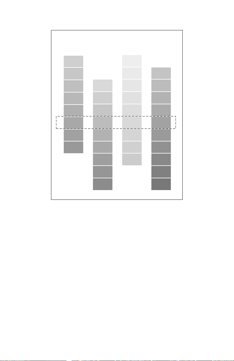
Color Reference Page
Cyan Magenta Yellow Black
-4
-6
-2
0
+2
+4
+6
+8
+10
-9
-7
-5
-3
-1
+1
+3
+5
+7
-4
-2
0
+2
+4
+6
+8
+10
-9
-7
-5
-3
-1
+1
+3
+5
+7
+9
9698-18
Manual color correction reference print
4. Overlay and compare the pre-printed primary Color Density Samples in the
Color Printer User Guide to the selected colors on the midline of the print. If
any primary color does not match, overlay and compare to an alternate
color. Note the number, -10 to +10, referenced to the alternate choice.
5. Press the right arrow on the front panel to scr oll to the Adjust <color>:+0
menu for the primary color you wish to change.
6. Press the arrow keys to increment the displayed value (from -10 to +10) to
match the alternate color selected from the reference print. Then press OK.
An “*” indicates the selected value.
7. Repeat Step 4 through 6 for any other color that needs adjustment.
8. Press Exit to leave the Color Calibration menus.
Service Guide 85
Page 98
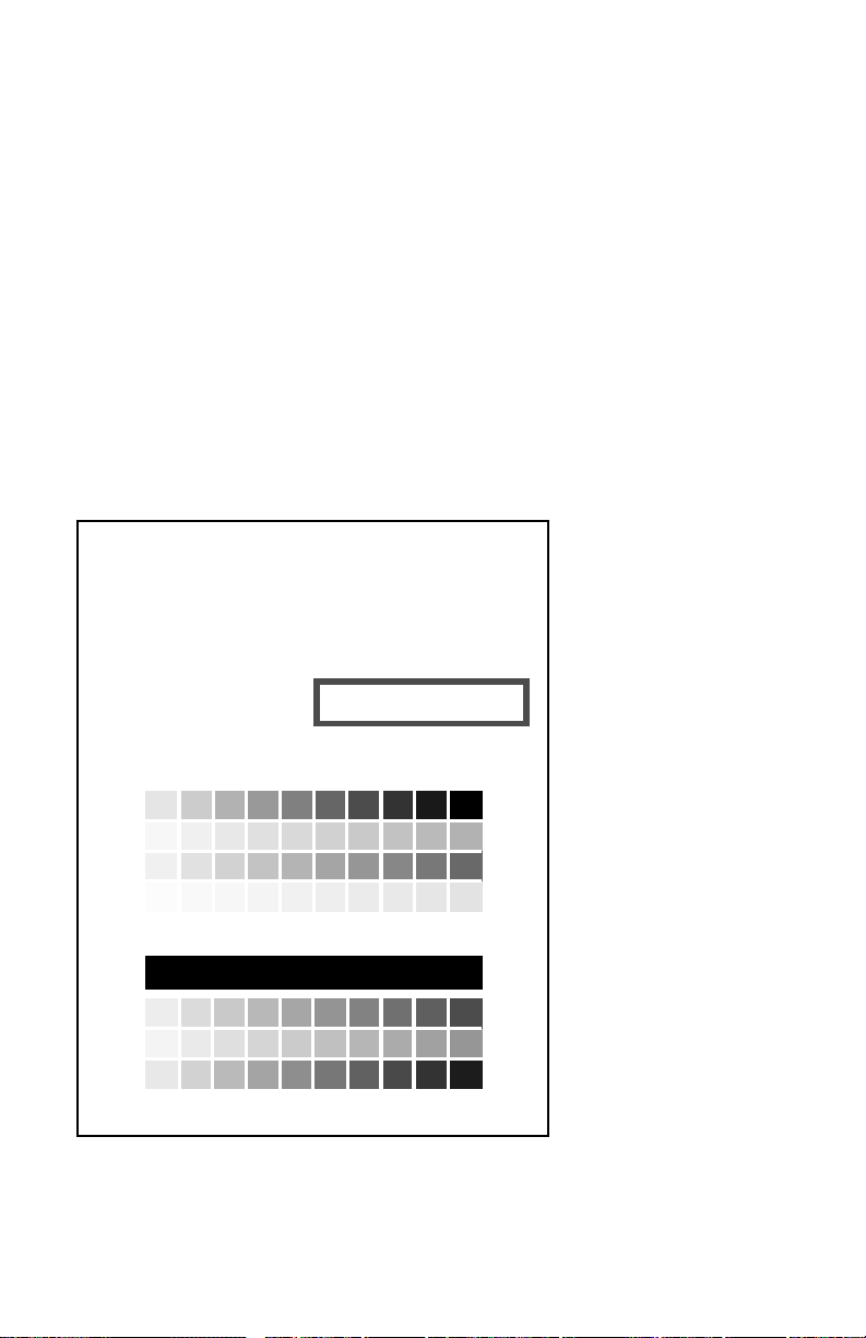
Calibrate for paper (Phaser 750 only)
®
The Calibrate for Paper menu adjust the printer for the grade of non-Tektronix paper
being printed on, as well as compensate for the current environmental conditions.
This adjustment applies only to Standard and Enhanced mode printing; Premium
mode is not affected by this adjustment. You may have to readjust the printer if you
switch to a different brand or grade of paper or if the temperature or humidity
changes significantly. The difference created by this calibration function may not be
apparent for prints made when the relative humidity is over 20%.
1. Press the Help button on the front panel to scroll the Print Quality menu.
2. Scroll to the Calibrate for Paper menu item and press Print. The printer
will print out 11 test pages.
3. Look at each of the 11 References Pages printed by the printer. Each prints
with a different transfer setting: (-10, -8, -6, -4, -2, 0, +2, +4, +6, +8, +10).
4. After deciding which page looks best on your brand or grade of paper, enter
in the front panel menu Adjust Transfer Setting the transfer setting
value (-10 to +10) of the page that looks best.
Phaser
750 Color Printer
Calibrate for Paper
The Calibrate for Paper menu
as compensate for the current environmental conditions. This adjustment applies only to Standard and Enhanced
mode printing; Premium mode is not affected by this adjustment. You may have to readjust the printer if you switch
to a different brand or grade of paper or if the temperature or humidity changes significantly.
Step 1.
Review each of the Reference pages.
Look at each of the 11 References Pages printed by the
printer. Each prints with a different transfer setting:
(-10, -8, -6, -4, -2, 0, +2, +4, +6, +8, +10).
Step 2.
Select a Transfer Setting based on your
evaluation of the prints.
After deciding which page looks best
in the front panel menu Adjust Transfer Setting the
transfer setting value (-10 to +10) of the page that looks
best.
helps you adjust the printer for the grade of non-Tektronix paper you print on, as well
This page was printed with Transfer Setting = <<<>>
on your paper
, enter
A B C D E F G H I J K L M N O P Q R S T U V W X Y Z abcdefghijklmnopqrstuvwxyz
A B C D E F G H I J K L M N O P Q R S T U V W X Y Z abcdefghijklmnopqrstuvwxyz
A B C D E F G H I J K L M N O P Q R S T U V W X Y Z abcdefghijklmnopqrstuvwxyz
A B C D E F G H I J K L M N O P Q R S T U V W X Y Z abcdefghijklmnopqrstuvwxyz
A B C D E F G H I J K L M N O P Q R S T U V W X Y Z abcdefghijklmnopqrstuvwxyz
A B C D E F G H I J K L M N O P Q R S T U V W X Y Z abcdefghijklmnopqrstuvwxyz
A B C D E F G H I J K L M N O P Q R S T U V W X Y Z abcdefghijklmnopqrstuvwxyz
A B C D E F G H I J K L M N O P Q R S T U V W X Y Z abcdefghijklmnopqrstuvwxyz
The Calibrate for Paper test page
86 Phaser 740 and 750 Color Printers
Page 99

Cleaning and Maintenance
Service preventive maintenance procedure
Whenever you check, service, or repair a printer, you should perform the following
procedures. Cleaning the printer, as outlined in the following steps, assures proper
operation of the printer and reduces the probability of having to service the printer in
the future.
The frequency of use and the type of paper a customer prints on determines how
critical cleaning the machine is. Users of ordinary Bond paper (copier paper) should
have very few problems since this paper is smooth and relatively dust-free. You
should thoroughly inspect and clean these printers.
Ask each printer customer about the type of paper he or she uses so that you can be
sure to clean the parts of the printer that particular paper may affect. If a customer is
printing on the more unusual or dustier papers, then you should pay particular
attention to these printer parts:
■
The standard pick roller
■
The multi-purpose pick roller (should be replaced at 30 k prints)
■
The multi-purpose tray cork separator (should be replaced when multipurpose pick roller is replaced)
■
The feed rollers
■
The auto-duplex unit rollers
■
The cabinet interior
■
The exit rollers
Service Guide
87
Page 100

Recommended tools
■
Toner vacuum cleaner
■
Suction bulb (air blower)
■
Cleaning water
■
Lint-free wipes
■
Cotton swabs
■
Imaging unit cover
■
Isopropyl alcohol (greater than 90% pure)
Cleaning
1.
Turn off the printer.
2.
Remove the imaging unit and immediately cover it to protect it from the
light.
3.
Remove the toner cartridges.
4.
Remove the fuser.
5.
Remove the paper tray.
6.
Slide out the paper feeder.
7.
Clean the accumulator belt home position sensor with a dry cotton swab.
8.
Clean all printer rollers, except the second bias transfer roller, with alcoholdampened wipes only. Never apply alcohol on the second bias transfer
roller.
9.
Clean the laser window with puffs of air from the suction bulb. Alternately,
you can vacuum the window clean.
10.
Wipe of f the pre-exposur e lamp bezel and the pr e-transfer lamp bezel with a
lint-free wipe.
11.
Vacuum out the interior of the printer.
88
Phaser 740 and 750 Color Printers
 Loading...