

Page 1
Phaser
Color Printer
Service
Manual
®
7300
Page 2

Page 3

PHASER® 7300
COLOR PRINTER
SERVICE MANUAL
Warning: The following servicing instructions are for
use by qualified service personnel only. To
avoid personal injury, do not perform any
servicing other than that contained in
operating instructions unless you are qualified
to do so.
This printing: September 2002
071-0862-00
i
Page 4

Copyright © 2002, Xerox Corporation. All Rights Reserved. Unpublished rights reserved under the
copyright laws of the United States. Contents of this publication may not be reproduced in any form
without permission of Xerox Corporation.
Copyright protection claimed includes all forms of matters of copyrighted materials and information now
allowed by statutory or judicial law or hereinafter granted, including without limitation, material generated
from the software programs which are displayed on the screen such as styles, templates, icons, screen
displays, looks, etc.
XEROX®, The Document Company®, the stylized X®, CentreWare®, DocuPrint®, Made For Each
®
Other
, Phaser®, PhaserShare®, and the TekColor® icon are registered trademarks of Xerox Corporation.
infoSMART™, PhaserPort™, PhaserPrint™, PhaserSMART™, PhaserSym™, PhaserTools™, and the
TekColor™ name are trademarks of Xerox Corporation. Total Satisfaction Services
SM
is a service mark of
Xerox Corporation.
Adobe®, Acrobat® Reader®, and PostScript® are registered trademarks of Adobe Systems Incorporated.
Apple®, LaserWriter®, LocalTalk®, Macintosh®, Mac® OS, and AppleTalk®are registered trademarks of
Apple Computer Incorporated.
PCL® and HP-GL® are registered trademarks of Hewlett-Packard Corporation.
MS-DOS® and Windows® are registered trademarks of Microsoft Corporation.
Novell® and NetWare® are registered trademarks of Novell, Incorporated.
Sun® and Sun Microsystems® are registered trademarks of Sun Microsystems, Incorporated. SPARC® is a
registered trademark of SPARC International, Incorporated. SPARCstation™ is a trademark of SPARC
International, Incorporated, licensed exclusively to Sun Microsystems, Incorporated.
UNIX® is a registered trademark in the US and other countries, licensed exclusively through X/Open
Company Limited.
This product includes an implementation of LZW licensed under U.S. Patent 4,558,302.
This product uses code for SHA-1 written by John Halleck, which is being used by his permission.
Other marks are trademarks or registered trademarks of the companies with which they are associated.
PANTONE® Colors generated by the Phaser 7300 Color Printer may not match PANTONE-identified
solid color standards. Use current PANTONE Color Reference Manuals for accurate colors.
PANTONE Color simulations are only obtainable on this product when driven by qualified
Pantone-licensed software packages. Contact Pantone, Inc. for a current list of qualified licensees.
ii Phaser 7300 Color Printer Service Manual
Page 5

Safety Terms
Manual Terms
Various terms are used throughout this manual to either provide additional
information on a specific topic or to warn of possible danger that might be present
during a procedure or action. Be aware of all symbols and terms when they are used,
and always read NOTE, CAUTION and WA RN I NG messages.
NOTE:
CAUTION:
WARNI NG:
Product Terms:
CAUTION:
DANGER:
A NOTE may indicate an operating or maintenance procedure,
practice or condition that is necessary to efficiently accomplish a task.
A
NOTE may also provide additional information related to a specific
subject or add a comment on the results achieved through a previous
action.
A CAUTION indicates an operating or maintenance procedure,
practice or condition that, if not strictly observed, could result in
damage to, or destruction of, equipment.
A WARNING indicates an operating, or maintenance procedure,
practice or condition that, if not strictly observed, could result in injury or
loss of life.
A personal injury hazard exists that may not be apparent. For example,
a panel may cover the hazardous area.
A personal injury hazard exists in the area where you see the sign.
iii
Page 6

Power Safety Precautions
Power Source
For 110 VAC printers, do not apply more than 127 volts RMS between the supply
conductors or between either supply conductor and ground. Use only the specified
power cord and connector. For 220 VAC printers, do not apply more than 240 volts
RMS between the supply conductors or between either supply conductor and ground.
Use only the specified power cord. This manual assumes that the reader is a qualified
service technician.
Warning: Plug the three-wire power cord (with grounding prong)
into a grounded AC outlet only. If necessary, contact a
licensed electrician to install a properly grounded outlet. If
the product loses it’s ground connection, contact with
conductive parts may cause an electrical shock.
Disconnecting Power
Warning: Turning the power off using the On/Off switch does not
Disconnect the power plug by pulling the plug, not the cord.
■ Disconnect the power plug if the power cord or plug is frayed or otherwise
damaged,
■ Or if any liquid or foreign material is spilled into the case,
■ Or if the printer is exposed to moisture,
■ Or if the printer is dropped or damaged,
■ Or if you suspect that the product needs servicing or repair,
■ Or whenever you clean the product.
completely de-energize the printer. You must also
disconnect the printer power cord from the AC outlet.
Position the power cord so that it is easily accessible during
servicing so that you may power down the printer during
an emergency.
iv Phaser 7300 Color Printer Service Manual
Page 7

Electrostatic Discharge (ESD) Precautions
Some semiconductor components, and the respective sub-assemblies that contain
them, are vulnerable to damage by electrostatic discharge (ESD). These components
include integrated circuits (ICs), Large-Scale Integrated circuits (LSIs), field-effect
transistors and other semiconductor chip components. The following techniques will
reduce the occurrence of component damage caused by static electricity:
Caution: Be sure the power is off and observe all other safety
precautions.
■ Immediately before handling any semiconductor component assemblies,
drain the electrostatic charge from your body. This can be accomplished by
touching an earth ground source or by wearing a wrist strap device
connected to an earth ground source. Wearing a wrist strap will also
prevent accumulation of additional bodily static charges. (Be sure to
remove the wrist strap before applying power to the unit under test to avoid
potential shock.)
■ After removing a static sensitive assembly from it’s anti-static bag, place it
on a grounded conductive surface such as aluminum foil. If the anti-static
bag is conductive, you may ground the bag and use it as a conductive
surface.
■ Do not use freon-propelled chemicals. These can generate electrical charges
sufficient to damage some devices.
■ Do not remove a replacement component or electrical sub-assembly from its
protective package until you are ready to install it.
■ Immediately before removing the protective material from the leads of a
replacement device, touch the protective material to the chassis or circuit
assembly into which the device will be installed.
■ Minimize body motions when handling unpackaged replacement devices.
Motion such as your clothes brushing together, or lifting a foot from a
carpeted floor can generate enough static electricity to damage an
electro-statically sensitive device
■ Handle IC’s and EEPROM’s carefully to avoid bending pins.
■ Pay attention to the direction of parts when mounting or inserting them on
Printer Circuit Boards (PCB’s).
v
Page 8

Service Safety Summary
General Guidelines
For qualified service personnel only: Refer also to the preceding Users Safety
Summary.
Avoid servicing alone: Do not perform internal service or adjustment of this product
unless another person capable of rendering first aid or resuscitation is present.
Use care when servicing with power: Dangerous voltages may exist at several
points in this product. To avoid personal injury, do not touch exposed connections and
components while power is on. Disconnect power before removing the power supply
shield or replacing components.
Do not wear jewelry: Remove jewelry prior to servicing. Rings, necklaces and other
metallic objects could come into contact with dangerous voltages and currents.
Power source: This product is intended to operate from a power source that will not
apply more then 250 volts rms for a 220 volt AC outlet or 130 volts rms for a 110 volt
AC outlet between the supply conductors or between either supply conductor and
ground. A protective ground connection by way of the grounding conductor in the
power cord is essential for safe operation.
Warning Labels
Read and obey all posted warning labels. Throughout the printer, warning labels are
displayed on potentially dangerous components. As you service the printer, check to
make certain that all warning labels remain in place.
Safety Interlocks
Make sure covers and panel are in place and that all interlock switches are all
functioning correctly after you have completed a printer service call. If you bypass an
interlock switch during a service call, use extreme caution when working on or
around the printer.
vi Phaser 7300 Color Printer Service Manual
Page 9
Servicing Electrical Components
Before starting any service procedure, switch off the printer power and unplug the
power cord from the wall outlet. If you must service the printer with power applied,
be aware of the potential for electrical shock.
Warning: Turning the power off using the On/Off switch does not
completely de-energize the printer. You must also
disconnect the printer power cord from the AC outlet.
Position the power cord so that it is easily accessible during
servicing so that you may power down the printer during
an emergency.
Warning: Do not touch any electrical component unless you are
instructed to do so by a service procedure.
S7300-02
Servicing Mechanical components
Manually rotate drive assemblies to inspect sprockets and gears.
Warning: Do not try to manually rotate or manually stop the drive
assemblies while any printer motor is running
S7300-03
Servicing Fuser Components
Warning: This printer uses heat to fuse the toner image to a sheet of
paper. The Fuser Assembly is very hot. Switch off printer
power and wait at least 30 minutes for the Fuser to cool
before you attempt to service the Fuser Assembly or
adjacent components.
vii
Page 10

Regulatory Information
The equipment described in this manual generates and uses radio frequency energy. If
it is not installed properly in strict accordance with Xerox's instructions, it may cause
interference with radio and television reception or may not function properly due to
interference from another device. However, there is no guarantee that interference
will not occur in a particular installation. If this equipment does cause harmful
interference to radio or television reception, which can be determined by turning the
equipment off and on, the user is encouraged to try to correct the interference by one
or more of the following measures:
■ Reorient or relocate the receiver (device being interfered with).
■ Increase the separation between the printer and the receiver.
■ Connect the printer into an outlet on a circuit different from that which the
receiver is connected.
■ Route the interface cables on the printer away from the receiver
■ Consult the dealer, Xerox service, or an experienced radio/television
technician for help.
Changes or modifications not expressly approved by Xerox can affect the emission
and immunity compliance and could void the user's authority to operate this product.
To ensure compliance, use shielded interface cables. A shielded parallel cable can be
purchased directly from Xerox at www.xerox.com/officeprinting/7300supplies
Xerox has tested this product to internationally accepted electromagnetic emission
and immunity standards. These standards are designed to mitigate interference caused
or received by this product in a normal office environment. This product is also
suitable for use in a residential environment based on the levels tested.
.
In the United States this product complies with the requirements of an unintentional
radiator in part 15 of the FCC rules. Operation is subject to the following two
conditions: (1) this device may not cause harmful interference; (2) this device must
accept any interference received, including interference that may cause undesired
operation.
This digital apparatus does not exceed the Class B limits for radio noise emissions
from digital apparatus set out in the Radio Interference Regulations of the Canadian
Department of Communications, ICES-003.
Le présent appareil numérique n'émet pas de bruits radioélectrique dépassant les
limits applicables aux appareils numériques de la classe B prescrites dans le
Réglement sur le brouillage radioélectrique édicté par le ministere des
Communications du Canada, ICES-003.
viii Phaser 7300 Color Printer Service Manual
Page 11

Declaration of Conformity
Xerox Corporation, declares, under our sole responsibility that the printer to which
this declaration relates, is in conformity with the following standards and other
normative documents:
In the European Union
following the provisions of the Low Voltage Directive 73/23/EEC and its
amendments:
EN 60950
(IEC 950)
"Safety of Information Technology Equipment including Electrical Business
Equipment"
following the provisions of the Electromagnetic Compatibility Directive 89/336/EEC
and its amendments:
EN55022:1998
(CISPR 22)
EN61000-3-2:1
995
+A1:1998+A2:1
998.
(IEC61000-3-2)
EN61000-3-3:1
995
(IEC61000-3-3)
EN55024:1998
(CISPR 24)
CISPR 24 Immunity
Phenomena
Electrostatic Discharge IEC61000-4-2:1995 6kV Contact, 10kV Air
Radio-Frequency
Electromagnetic Field
(radiated)
"Limits and Methods of measurement of radio interference characteristics of
Information Technology Equipment." Class B.
"Part 3: Limits - Section 2: Limits for harmonic current emissions (equipment
input current less than or equal to 16A per phase)."
"Part 3: Limits - Section 3: Limitation of voltage fluctuations and flicker in
low-voltage supply systems for equipment with rated current less than or
equal to 16A."
"Information technology equipment - Immunity characteristics - Limits and
methods of measurement. "
Basic Standard Test Specification
IEC61000-4-3:1995 80-1000 MHz, 3V/m, 80% AM @ 1 KHz
Fast Burst Transients IEC61000-4-4:1995 5/50 Tr/Th ns, 5kHz Rep. Freq
0.5kV on Signal Lines
1kV on AC Mains
Line Surge IEC61000-4-5:1995 Combination wave
2.0kV Common mode
2.0kV Differential mode
ix
Page 12

CISPR 24 Immunity
Phenomena
Radio-Frequency
Electromagnetic Field
(Conducted)
Line voltage dips IEC61000-4-11:1994>95% dip for ½ cycle @ 50 Hz
Line voltage drop-out IEC61000-4-11:1994>95% dropout for 250 cycles @ 50 Hz
Basic Standard Test Specification
IEC61000-4-6:1996 0.15 - 80 MHz, 3V, 80% AM @ 1kHz
30% dip for 25 cycles @ 50 Hz
This product, if used properly in accordance with the user's instructions is neither
dangerous for the consumer nor for the environment.
A signed copy of the Declaration of Conformity for this product can be obtained from
Xerox.
Canadian Notice
This digital apparatus does not exceed the Class B limits for radio noise emissions
from digital apparatus as described in the radio interference regulations of the
Canadian Department of Communications.
Avis Canadien
Cet appareil numerique est conforme aux limites émission de bruits radioélectriques
pour les appareils de classe B stipulés das le réglement sur le brouillage radioéletrique
du Ministére des Communcations du Canada.
European Notice
This equipment was tested and is determined to be compliant with VDE requirements
for a Class B device.
Hinweis
Hiermit wird bescheinigt, dass der Babe Laserdrucker, in bereinstimmung mit den
Betimmunngen der Vfg 104ß 984 funkenstört ist. Der Deutschen Bundespost wurde
das Inverkehrbringen dieses Gertëes angqeigt und die Berechtigung zur berprufung
der Serie auf Einhaltung der Bestimmungen eingeräumt.
x Phaser 7300 Color Printer Service Manual
Page 13

Table of Contents
General Information 1 - 1
The Phaser 7300 Color Printer Overview...............................................................1 - 2
Phaser 7300 Printer Configurations................................................................1 - 3
Printer Memory and RAM Capabilities..........................................................1 - 5
Parts of the Printer ..................................................................................................1 - 6
Print Engine Base Configuration ....................................................................1 - 6
Printer Options - Lower Tray Deck (LTD) and
Lower Tray Assembly (LTA) ......................................................................1 - 7
Printer Options (cont’d) - Duplex Unit...........................................................1 - 8
Front Panel Configuration ......................................................................................1 - 9
Front Panel LED indicators: ...........................................................................1 - 9
Image Processor (IP) Board Components ....................................................1 - 10
Rear Panel Configuration of the IP Board ....................................................1 - 11
DIP Switches ................................................................................................1 - 12
Printer Specifications............................................................................................1 - 13
Physical Dimensions - Print Engine .............................................................1 - 13
Physical Dimensions - Options.....................................................................1 - 13
Printer Clearances .........................................................................................1 - 13
Functional Specifications..............................................................................1 - 14
Print Speeds ..................................................................................................1 - 14
Electrical Specifications ...............................................................................1 - 15
Environmental Specifications .......................................................................1 - 15
Media and Tray Specifications .....................................................................1 - 16
Error Messages and Codes 2 - 19
Accessing Error Codes and Fault History ....................................................2 - 19
Error Messages and Codes Index .........................................................................2 - 20
Service Flowchart .................................................................................................2 - 24
Using the Troubleshooting Procedures.........................................................2 - 25
General Notes on Troubleshooting...............................................................2 - 25
Service Diagnostics ..............................................................................................2 - 26
Enter without rebooting the printer (Hidden Service Menu):.......................2 - 26
Enter by rebooting the printer:......................................................................2 - 26
Service Diagnostics Key Press and Function Table .....................................2 - 26
Service Diagnostics Tests and Functions Table............................................2 - 27
Error Messages and Codes Procedures.................................................................2 - 37
Contents xi
Page 14

Troubleshooting 3 - 67
System Boot Sequence......................................................................................... 3 - 68
Power On Self Test (POST)......................................................................... 3 - 68
Printer Malefactions or Inoperable Printer Problems .................................. 3 - 71
Verifying Power Supply Operation ..................................................................... 3 - 72
Measuring Power Supply Voltages.............................................................. 3 - 72
POWER Connector Pinout .......................................................................... 3 - 72
Safety interlocks .......................................................................................... 3 - 73
The +5 VDC Loop ....................................................................................... 3 - 74
To verify the +5 volt loop is complete:........................................................ 3 - 74
Fuser Roller Resistances .............................................................................. 3 - 75
Multi-Sheet Pick .......................................................................................... 3 - 76
Media Skewing ............................................................................................ 3 - 76
Operating System and Application Problems ...................................................... 3 - 77
Network Problems ............................................................................................... 3 - 78
Print-Quality Problems ........................................................................................ 3 - 79
Test Prints, Adjustments, and NVRAM Resets 4 - 111
Test Print Samples ............................................................................................. 4 - 112
Automatic Density Control (ADC) Calibration Procedure................................ 4 - 116
Automatic Thickness Sensor (ATS) Calibration Procedure .............................. 4 - 118
Color Calibration ....................................................................................... 4 - 121
Margin Calibration..................................................................................... 4 - 121
Resetting NVRAM ............................................................................................ 4 - 122
Cleaning and Maintenance 5 - 125
Recommended tools................................................................................... 5 - 125
Periodically Replaced Parts ............................................................................... 5 - 125
Service Preventive Maintenance Procedures..................................................... 5 - 126
Cleaning the LED Lens.............................................................................. 5 - 126
Cleaning the Pick and Feed Rollers ........................................................... 5 - 127
Cleaning the ADC Sensor.......................................................................... 5 - 127
Cleaning the Registration Sensor............................................................... 5 - 127
Cleaning the Contacts ................................................................................ 5 - 127
FRU Disassembly 6 - 129
Orientation of the Printer ................................................................................... 6 - 131
General Notes on Disassembly .................................................................. 6 - 131
Preparation ................................................................................................. 6 - 131
Work Notes ................................................................................................ 6 - 132
Notations in the Disassembly Text ............................................................ 6 - 132
About Screw Colors................................................................................... 6 - 132
Disassembly Procedures .................................................................................... 6 - 133
xii Phaser 7300 Color Printer Service Manual
Page 15

Field Replaceable Units (FRU) Parts List 7 - 193
Using the parts list ..............................................................................................7 - 193
PL 1.0 - Covers ..........................................................................................7 - 194
PL 2.0 - MPT Pick Assembly .....................................................................7 - 196
PL 3.0 - Printer Control Components Boards.............................................7 - 198
PL 4.0 - Top Cover Inner Frame ................................................................7 - 200
PL 5.1 - Printer Unit Chassis (1 of 2) .........................................................7 - 202
PL 5.2 - Printer Unit Chassis (2 of 2) and Power Supplies ........................7 - 204
PL 6.1 - Paper Tray 1..................................................................................7 - 206
PL 6.2 - Lower Tray Deck & Lower Tray Assembly (Trays 2, 3, 4, 5) .....7 - 208
Kits......................................................................................................................7 - 210
Supplies and Accessories....................................................................................7 - 213
Manuals and CD’s ..............................................................................................7 - 213
Customer Replaceable Consumables..................................................................7 - 214
Paper and Media .........................................................................................7 - 215
Theory of Operation 8 - 219
Mechanical Process of the Printer ......................................................................8 - 220
Summary of the Printing Process .......................................................................8 - 221
Summary of the Paper Path ................................................................................8 - 226
Paper Fed from Tray 1 ................................................................................8 - 227
Paper Fed from Optional Trays ..................................................................8 - 228
Paper Fed from the Multi-Purpose Tray .....................................................8 - 229
Transfer Unit...............................................................................................8 - 230
Imaging Unit Up/Down Movement............................................................8 - 231
Transfer Unit Arm and Gear Up/Down Movement of the Imaging Units .8 - 232
Fuser and Paper Exit ...................................................................................8 - 233
Duplex Unit ................................................................................................8 - 234
Paper Jam Detection ...........................................................................................8 - 235
Paper Size Sensing......................................................................................8 - 236
Fuser Temperature Settings ................................................................................8 - 237
Cover Open Detection ........................................................................................8 - 238
Toner Detection ..................................................................................................8 - 239
Color Registration Detection ......................................................................8 - 241
Customer Replaceable Consumable Detection...........................................8 - 242
Customer Replaceable Consumable (CRC) Life Counter Behavior ..........8 - 242
Printer Components ............................................................................................8 - 244
Engine Controller Board Connectors..........................................................8 - 246
Sensors........................................................................................................8 - 248
Clutches, Motors and Solenoids .................................................................8 - 250
Wiring Diagrams 10 - 251
Contents xiii
Page 16

xiv Phaser 7300 Color Printer Service Manual
Page 17

General Information
The Xerox Phaser® 7300 Color Printer Service Manual is the primary document used
for repairing, maintaining, and troubleshooting the printer.
To ensure a complete understanding of the product, Xerox recommends participation
in Phaser 7300 printer service training.
Contents
The Phaser 7300 Color Printer Overview...............................................................................1 - 2
Phaser 7300 Printer Configurations........................................................................................1 - 3
Secure Prints, Proof Prints, Saved Prints and PDF Direct Printing........................................1 - 4
Power Saver Mode..................................................................................................................1 - 4
Printer Memory and RAM Capabilities..................................................................................1 - 5
Parts of the Printer ..................................................................................................................1 - 6
Print Engine Base Configuration ............................................................................................1 - 6
Printer Options - Lower Tray Deck (LTD) and Lower Tray Assembly (LTA) ....................1 - 7
Printer Options (cont’d) - Duplex Unit...................................................................................1 - 8
Front Panel Configuration ......................................................................................................1 - 9
Front Panel LED indicators: ...................................................................................................1 - 9
Image Processor (IP) Board Components ............................................................................1 - 10
Rear Panel Configuration of the IP Board ............................................................................1 - 11
DIP Switches ........................................................................................................................1 - 12
Printer Specifications ............................................................................................................1 - 13
Physical Dimensions - Print Engine .....................................................................................1 - 13
Physical Dimensions - Options.............................................................................................1 - 13
Printer Clearances .................................................................................................................1 - 13
Functional Specifications......................................................................................................1 - 14
Print Speeds ..........................................................................................................................1 - 14
Electrical Specifications .......................................................................................................1 - 15
Environmental Specifications ...............................................................................................1 - 15
Media and Tray Specifications .............................................................................................1 - 16
General Information 1 - 1
Page 18
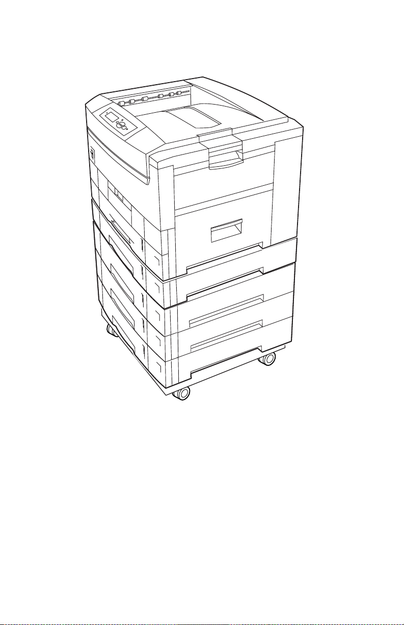
The Phaser 7300 Color Printer Overview
.
S7300-05
Phaser 7300 Printer with Lower Tray Assembly (LTA) and Lower Tray Deck (LTD)
The Phaser 7300 Printer combines a 4-color, LED-based, tandem-design tabloid print
engine, with an Xerox OPB Image Processor Board (IP) that supports Adobe’s
PostScript Level 3 page description language. The IP Board features a bi-directional
parallel interface. An optional Ethernet port for host communication is also available.
The Ethernet port supports EtherTalk 10/100baseT, Novell and TCP/IP. All printer
versions support the color PCL5c printer language.
A replaceable “Configuration Upgrade Chip” contains configuration information that
enables or disables built-in features as described below to allow customer upgrades
from7300B to 7300N models.
1 - 2 Phaser 7300 Color Printer Service Manual
Page 19

Phaser 7300 Printer Configurations
The printer is available in five configurations:
Features Printer Model
7300B 7300N 7300DN 7300DT 7300DX
Max print speed (see page 1-14) 30/37 30/37 30/37 30/37 30/37
Memory 128* 192* 192* 256* 384*
PostScript Fonts
136 Type 1
115 Central European Type 1
PCL5c
46 PCL fonts (more fonts are available
with the optional internal hard drive)
Job Pipelining Std Std Std Std Std
Proof print, Secure print, Saved jobs Opt** Opt** Opt** Std Std
PDF Direct print Opt** Opt** Opt** Std Std
2400 dpi resolutions No Std Std Std Std
A3 Bleeds No Std Std Std Std
Job Collation Opt** Opt** Opt** St d Std
Auto-Duplex Opt Opt St d Std Std
Printer Cart Opt Opt Opt Opt N/A
550-Sheet Feeder (LTA) Opt Opt Opt Std Opt
1650-High-Capacity Feeder (LTD) Opt Opt Opt Opt Std
10/100 Ethernet Network Capable No Std Std Std Std
USB, Parallel Std Std Std Std Std
Optional Hard Drive Opt Opt Opt Std Std
* All configurations support 2 memory slots; the maximum memory is 512 Mbytes.
** Requires the optional internal hard drive.
136 136 136 136 136
Std Std Std Std Std
General Information 1 - 3
Page 20

Secure Prints, Proof Prints, Saved Prints and PDF Direct Printing
These features are available only if the printer has a hard drive installed.
Note: These jobs are stored on the printer’s optional hard drive and
remain in the printer even when it is powered off. There is a
limit of 100 jobs on the hard drive, per type. When the printer
reaches the limit, it deletes the oldest job per type
automatically before adding the new one.
■ Secure Print: Print confidential documents. A 4-digit numeric
password-protected job is stored on the printer’s hard drive. The job prints
only after entering the 4-digit number on the printer’s front panel.
■ Proof Print: Prints only one copy of a multiple copy job so the user can
proof the copy. The user assigns a job name to the print job and the first set
is printed immediately for proofing. To print the remaining copies, select
the job name on the printer’s front panel. If the user does not want the
remaining copies the job can be cancelled from the printer’s front panel.
■ Saved Print: Stores jobs on the printer’s hard drive for print on demand.
■ PDF Direct Printing: The printer supports a native PDF image processor.
PDF Direct printing uses the printer’s currently defined imaging settings.
Auto sensing of PDF files are included in the emulation sensing and
switching logic when the PDF option is installed.
Power Saver Mode
To conserve power, the printer switches into Power Saver Mode after being idle for
user-selected amount of time. The printer consumes less than 70 watts of power in
Power Saver Mode. The printer leaves Power Saver Mode or “awakens” upon
receiving data or user interaction at the front panel.
Resolutions: The printer supports the following resolutions:
■ 600 x 600 dpi (Draft/Standard Mode)
■ 600 x 2400 dpi (Enhanced Mode)
The printer also accepts 300 x 300 dpi files from PCL legacy drivers, PCL bit map
fonts, and PCL bit map images, although these are imaged at 600 x 600 dpi.
The printer supports these optional lower tray combinations:
■ One 550-Sheet Feeder (LTA)
■ Two 550-Sheet Feeder
■ One 1650-Sheet High-Capacity Feeder (LTD)
■ One 550-Sheet Feeder and one 1650-Sheet High-Capacity Feeder
1 - 4 Phaser 7300 Color Printer Service Manual
Page 21

Printer Memory and RAM Capabilities
The printer features two memory slots each of which can contain a 64-, 128-, or
256-Mbyte, 144 pin, SODIMM modules. Any slot may be used for any memory size
SODIMM. Therefore, slot combinations are allowed providing configurations of 128,
192, 256, 320, 384, and up to 512 Mbytes.
The image processor board also contains 16-kilobytes of non-volatile memory
(NVRAM). NVRAM is used to store configuration values that can be set on the
printer.
RAM modules have the following characteristics:
■ 144 pin SODIMM
■ Serial presence detect
■ 3.3 Volt
■ 100 MHz PC100 or 133 MHz PC133
The Startup Page and the Configuration Page list the amount of RAM installed in the
printer.
If a SODIMM does not meet the image processor board’s specifications one of the
following will occur:
■ POST fails and displays “RAM Error” on the front panel.
■ POST will continue, but the printer will display a soft fault “RAM DIMM
presence”.
■ The image processor board will not boot at all.
General Information 1 - 5
Page 22
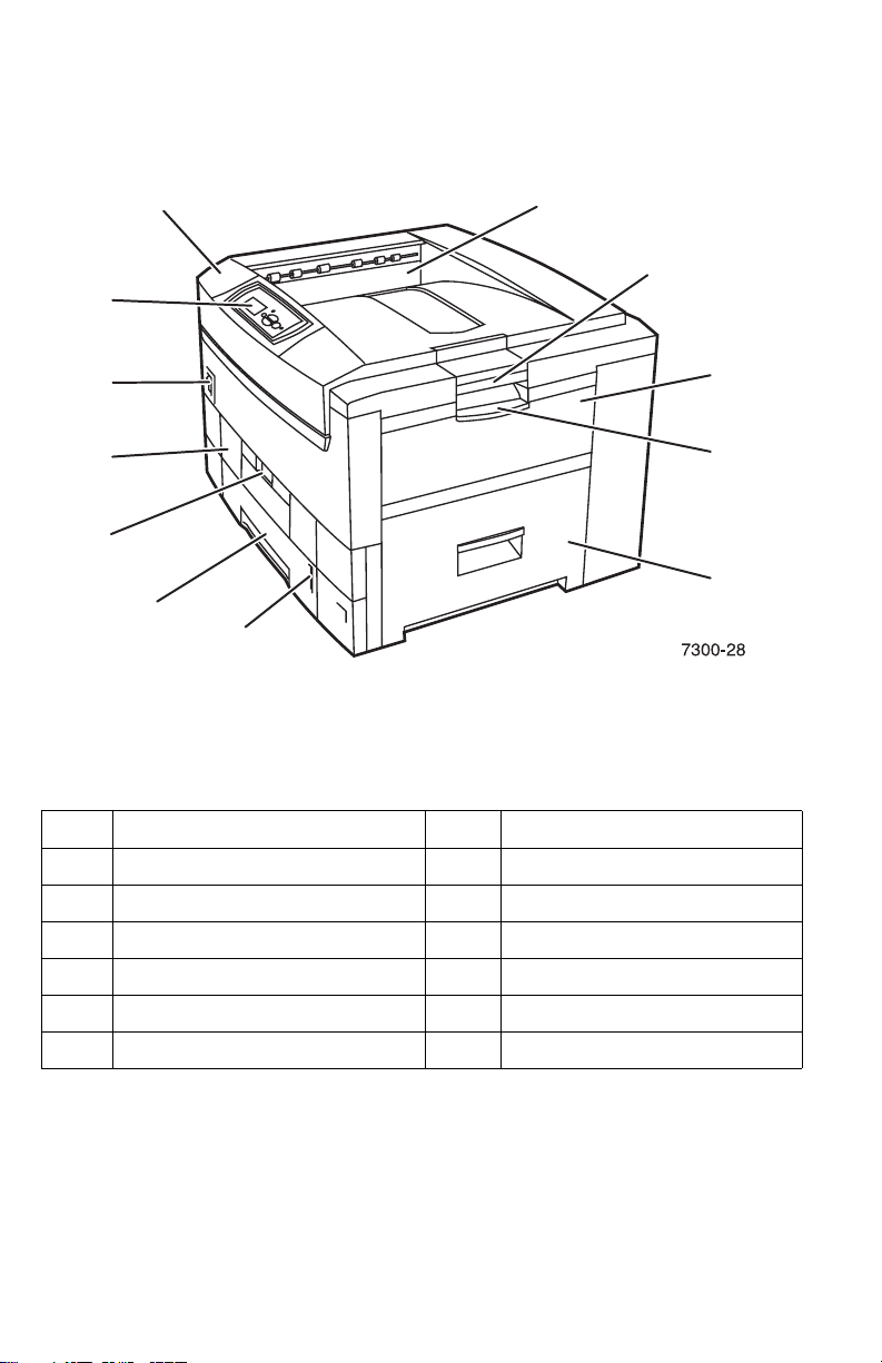
Parts of the Printer
Print Engine Base Configuration
3
12
9
4
5
6
7
8
Base Configuration, right-front view
Item Description Table
No. Description No. Description
Top Output Tray
1
Top Cover
2
Front Panel
3
Power Switch
4
Duplex Unit (optional - shown closed)
5
Duplex Unit Release
6
Tray 1
7
Paper Level Gauge
8
Top Cover Release
9
Multi-Purpose Tray
10
Multi-Purpose Tray Release
11
Right Cover Door A
12
10
11
12
1 - 6 Phaser 7300 Color Printer Service Manual
Page 23
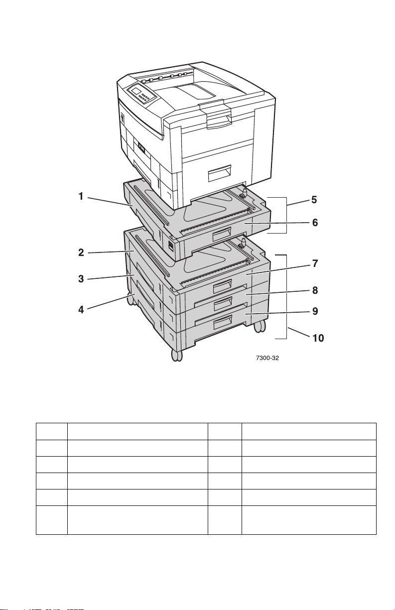
Printer Options - Lower Tray Deck (LTD) and Lower Tray Assembly (LTA)
!
"
7300-32
Item Description Table
No. Description No. Description
Tray 2
1
Tray 3
2
Tray 4
3
Tray 5
4
Lower Tray Assembly
5
550-sheet feeder (LTA)
Right Door B
6
Right Door C
7
Right Door D
8
Right Door E
9
Lower Tray Deck
10
1650 High-Capacity Feeder (LTD)
#
$
%
&
'
General Information 1 - 7
Page 24
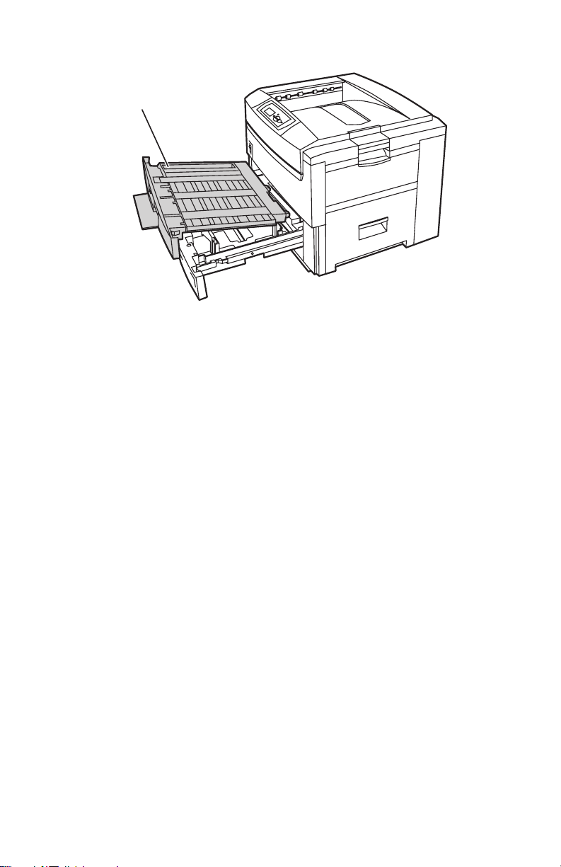
Printer Options (cont’d) - Duplex Unit
1
Duplex Unit shown with Tray 1
1. Duplex Unit
■ The Duplex Unit attaches to the top of Tray 1.
7300-33
■ When opening the Duplex Unit, Tray 1 opens also to support the Duplex
Unit.
1 - 8 Phaser 7300 Color Printer Service Manual
Page 25
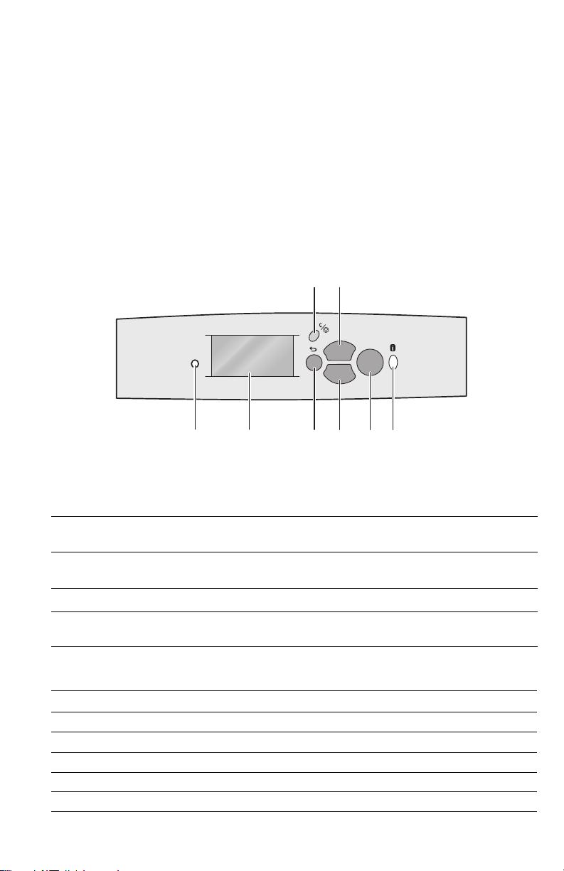
Front Panel Configuration
The Front Panel consists of one tricolor LED, a display window and six functional
keys. These keys navigate the menu system, perform functions and select modes of
operation for the printer.
Front Panel LED indicators:
■ Green = Ready to Print or Printing
■ Flashing Green = Receiving, Processing Data, Printing or Power Saver
Mode
■ Flashing Yellow = Warning
■ Flashing Red = Error
Phaser 7300
OK
12345678
7300-27
Phaser 7300 Printer Front Panel Configuration
Front Panel Key Descriptions
LED (Power/Status)
1
Graphic front panel display
2
Cancel Key - cancels printing
3
Back Key - moves back to the
4
previous menu.
Up Arrow Key - scrolls up the menu
5
system
Down Arrow Key - scrolls down the
6
menu system
OK (select) Key
7
Information Key - for additional
8
explanation or help
Front Panel Shortcuts
Mode Press this selection at Power On
Skip execution of POST diagnostics OK
Print Service Diagnostics Map INFO
Reset PostScript NVRAM BACK+OK
Password Bypass UP+DOWN
Enter Service Diagnostics BACK+INFO
General Information 1 - 9
Page 26
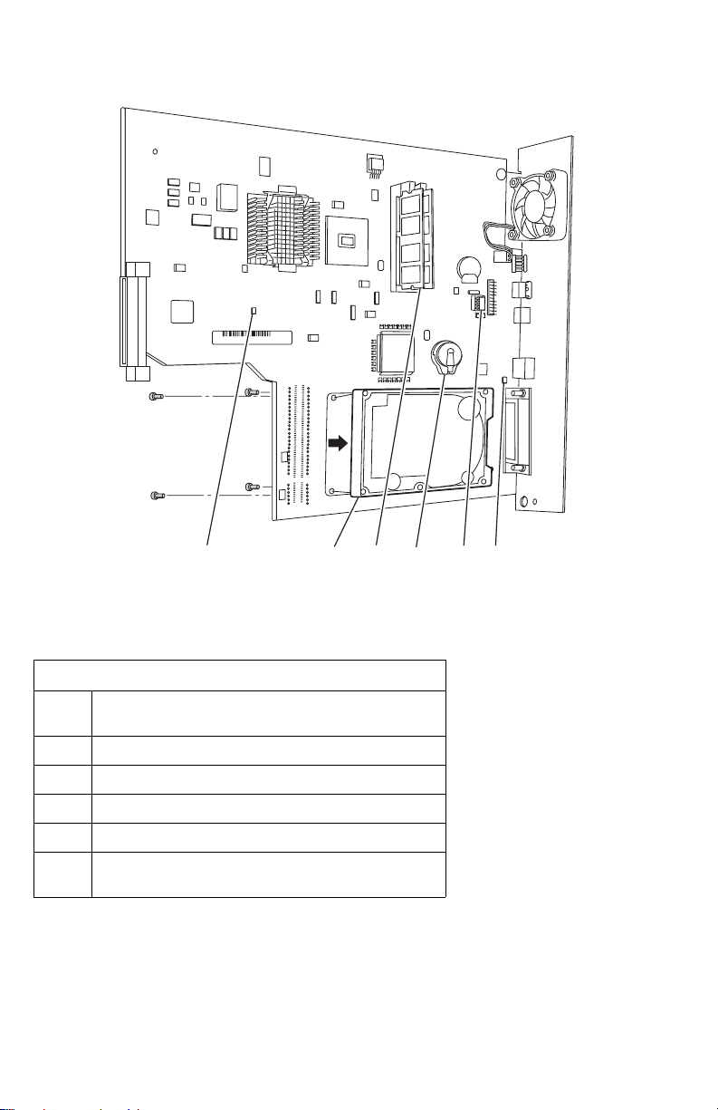
Image Processor (IP) Board Components
21 3 4 5 6
S7300-152
No. Description
1 LED GI02 “health” : Flashes to indicate proper CPU
operation.
2 Hard Drive (optional)
3 Memory (RAM) SODIMM 1 and SODIMM 2
4 Configuration Upgrade Chip (“i” Button)
5 NVRAM
6 LED GI03: On indicates 10baseT connection and Off
indicates a 100baseT connection.
1 - 10 Phaser 7300 Color Printer Service Manual
Page 27
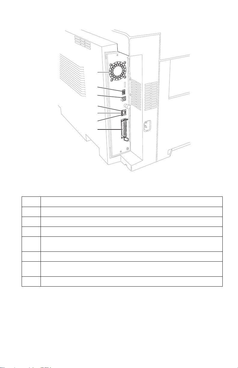
Rear Panel Configuration of the IP Board
1
2
3
4
5
6
7
S7300-173
No. Description
Image Processor Board Fan
1
DIP switches
2
USB Port
3
The ethernet port LED TD light is Off when the printer is connected to an ethernet
4
network. It blinks yellow while data is transmitted to the host
Ethernet Port (Not supported on the 7300B)
5
The ethernet port LED RD light is off when the printer is not connected to an
6
ethernet network. It blinks green when data is received from the host.
Parallel Port
7
General Information 1 - 11
Page 28
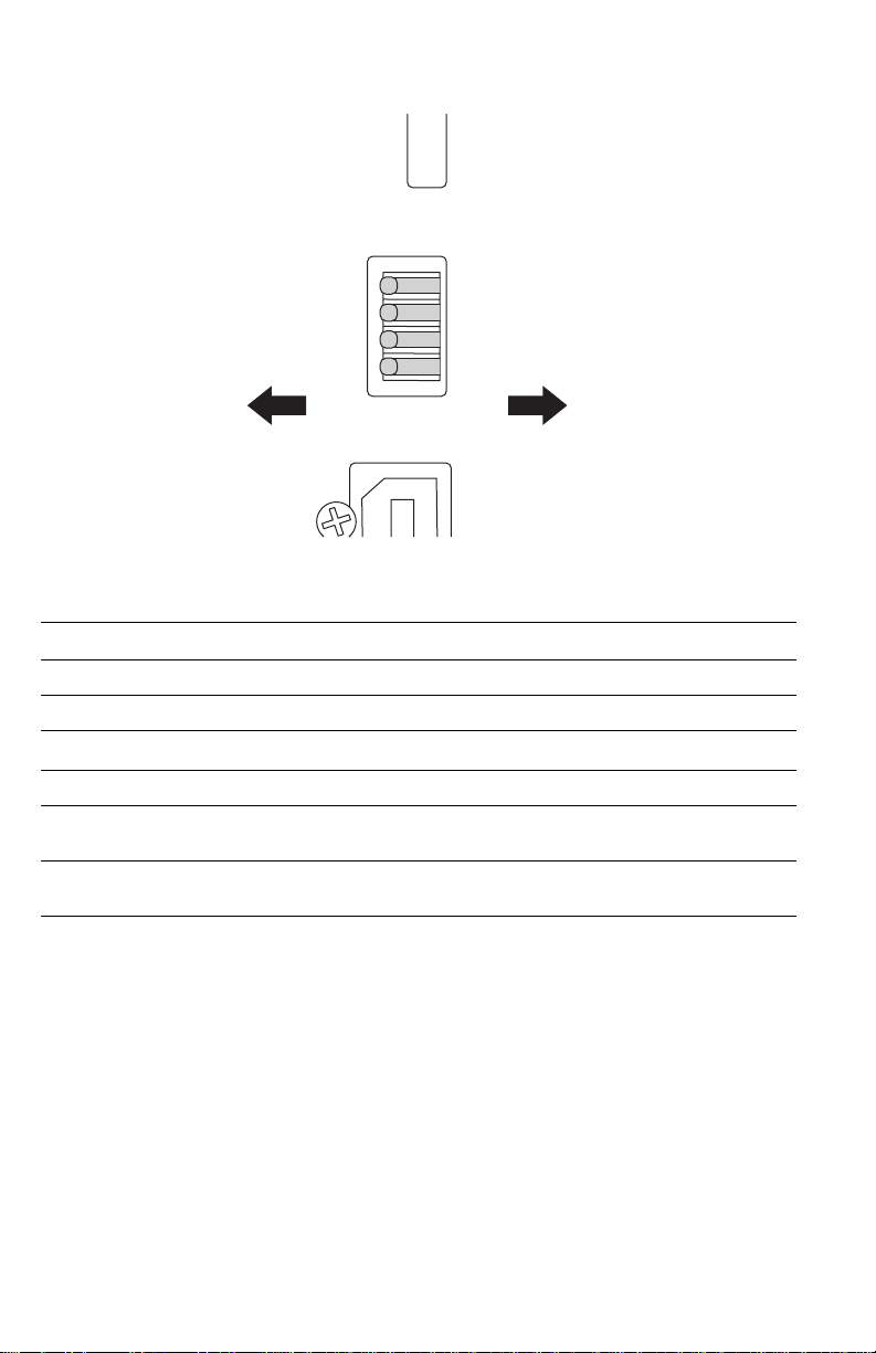
DIP Switches
Open Closed
4
3
2
1
Back
The DIP switches are defined as follows:
Mode Switch 1 Switch 2 Switch 3* Switch 4**
Customer Mode Open Open
Service Mode Open Closed
Developer Mode (no POST)
Disaster Recovery (Vx Works only) Closed Open
* Switch 3 selects whether PostScript (CLOSED) or Vx Works (OPEN) is available on the rear
panel serial port.
** Switch 4 is an Image Processor CPU Reset switch, normally (OPEN). Do not leave in the
(CLOSED) position.
Closed Closed
Front
S7300-173a
1 - 12 Phaser 7300 Color Printer Service Manual
Page 29
Printer Specifications
Physical Dimensions - Print Engine
Dimensions Specification
Height: 460 mm (18.1 in.)
Width: 666 mm (26.2 in.)
Depth: 626 cm (24.6 in.)
Weight: 68 kgs (149 lbs.)
Physical Dimensions - Options
Dimensions Specification
Optional 550-Sheet Feeder (Tray 2)
Width: 666 mm (26.2 in.)
Depth: 626 cm (24.6 in.)
Weight: 23 kgs (50 lbs.)
Optional 1650 Sheet High-Capacity Feeder (Trays 3 - 5)
Width: 666 mm (26.2 in.)
Depth: 626 cm (24.6 in.)
Weight: 74 kgs (163 lbs.)
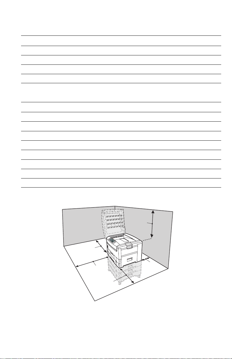
Printer Clearances
70 cm
(28 in.)
42 cm
(16.5 in.)
42 cm
(16.5 in.)
42 cm
(16.5 in.)
General Information 1 - 13
20 cm
(8 in.)
Page 30
Functional Specifications
Characteristic Specification
Printing process Electro-photographic, four color (CMYK) tandem transfer printing
Color medium Four toner cartridges, each contain one of four colors: cyan, magenta,
Resolution /
Addressability
Operating Modes Running Mode: Print Engine capable of making prints immediately.
Warm-up time 30 seconds from cold start (power off condition)
Print Speeds
yellow or black. The toner is a nonmagnetic, monocomponent contact
medium.
Standard and Draft 600 x 600 dpi (Factory Default)
Enhanced 600 x 2400 dpi*
* Not available on the Phaser 7300B.
** Not Available on the Phaser 7300B or Phaser 7300N.
Ready Mode: 15 seconds from completion of a print.
Power Saver Mode: Entered after a specified period of Print Engine
inactivity since completion of the last print.
Print Mode (Color) Ltr / A4 Ltr/A4
Duplex
600 x 600 30/37 28/32 16/20 15/18
2400 x 600 16/16 16/16 9/9 9/9
Transparencies 10/15 N/A N/A N/A
Thick Card Stock
Thin Card Stock
Envelopes
Glossy
Business Card
Greeting Card
CD/DVD Labels and
Inserts
10/10 N/A 6/6 N/A
10/10 N/A N/A N/A
A3/Tabloid A3/Tabloid
Duplex
1 - 14 Phaser 7300 Color Printer Service Manual
Page 31

Electrical Specifications
Characteristic Specification
Primary line voltages 110 - 127 VAC (115 VAC nominal)
Primary voltage
frequency range
Power consumption Peak: 1600 W
Primary voltage fusing 115 VAC configuration – 20 Amp
Frequency 50Hz or 60Hz +2%
Power Supplies Low-Voltage Power Supply
220 to 240 VAC (230 VAC nominal)
50 (48 to 52) or 60 (58 to 62) Hz
Normal Operation: 800 W
Idle: 250 W
Power Saver: 70 W
230 VAC configuration – 15 Amp
+5V Logic circuit power supply, LED
+34V Motor and drive voltage,
+12V High-voltage power supply, Paper
High-Voltage Power Supply
(CH) -1000 to -1400+50V Voltage to charge roller
(DB) -50 to -300V/+300V Voltage to developing roller
(SB) -300 to -450/0V Voltage to toner supply roller
(TR) C: 0 to 7KV
K,Y,M: 0 TO 6KV
Head
high-voltage power supply
thickness sensor power supply
Voltage to transfer unit (variable)
Environmental Specifications
Characteristic Specification
Temperature
Operating
Storage
Transport
Humidity
Operating
Storage
Transport
Altitude
Operating
Non-operating
General Information 1 - 15
10 to 32 oC (50 to 89.6 oF)
o
0 to 43
-10 to 43
Relative Humidity (50 - 70% to assure the best print-quality)
20 - 80%
10 - 90%
10 - 90%
0 to 2500 m (8,000 ft.) at 25 oC
0 to 6000 m (20,000 ft.)
C (32 to 109.4 oF)
o
C (-14 to 109.4 oF)
Page 32

Environmental Specifications (cont'd.)
Characteristic Specification
Vibration/shock
Operating
Non-Operating (vibration)
Non-operating (shock)
Acoustic Noise (operating) Standby: 45 dBa, Running: 54 dBa, Impulse: 57 dBa
May drop any side or corner 50 mm (2 in.) without impairment of
subsequent operation.
On five mutually perpendicular axes: 0.5 g, 25-minute sweep, 5
to 200 to 5 Hz, 100 to 200 sec./sweep cycle. No resonant
frequencies below 50 Hz.
15 g, trapezoidal flared pulse, 20 msec each axis.
Media and Tray Specifications
Specification Supported
Printable
Area
Supported
Paper
Sizes
Supported
Paper
Types And
Weights
Minimum margins = 5 mm (0.2 in.) on all sides
Maximum paper size = 304.8 mm x 914.40 mm (12 in. x 36 in.)
Minimum paper size = 105 mm x 148 mm (4.13 in. x 5.83 in.)
Paper Type Size
Letter 8.5 x 11 in.
Legal 8.5 x 14 in.
Executive 7.25 x 10.5 in.
Tabloid 11 x 17 in.
Tabloid Extra 12 x 18 in.
Statement 5.5 x 8.5 in.
US Folio 8.5 x 13 in.
A4 210 x 297 mm
A3 297 x 420 mm
SRA3 320 x 450 mm
A5 148 x 210 mm
A6 105 x 148 mm
ISO B5 176 x 250 mm
B5 JIS 182 x 257 mm
B4 JIS 257 x 364 mm
Custom Sizes
Banner 12.9 x 36 in.
Typ e We igh t
Plain Paper 64 - 120 g/m2 (17 - 32 lb. Bond)
Light Paper 64 - 75 g/m
Medium Paper 75 - 90 g/m
Medium Heavy Paper 90 - 105 g/m
Heavy Paper 105 - 120 g/m
Transparency Phaser® 35-Series ONLY
Thin Card Stock 120 - 163 g/m
Thick Card Stock 163 - 203 g/m
Labels N/A
Letterhead 64 - 120 g/m
Glossy Coated Paper 120 - 163 g/m
Business and Greeting Card N/A
CD/DVD Labels and Inserts N/A
2
(17 - 20 lb. Bond)
2
(20 - 24 lb. Bond)
2
(24 - 28 lb. Bond)
2
(28 - 32 lb. Bond)
2
(44 - 60 lb. Cover)
2
(60 - 75 lb. Cover)
2
(17 - 32 lb. Bond)
2
(81 - 110 lb. Book
Tray(s)
Trays
All Trays
All Trays
All Trays
All Trays
All Trays
MPT Only
All Trays
All Trays
All Trays
All Trays
All Trays
MPT / Tray 1
MPT Only
All Trays
All Trays
MPT / Tray 1
MPT Only
All Trays
MPT / Tray 1
MPT / Tray1
MPT / Tray 1
MPT / Tray 1
MPT / Tray 1
All Trays
MPT Only
MPT Only
All Trays
MPT / Tray 1
MPT Only
MPT Only
1 - 16 Phaser 7300 Color Printer Service Manual
Page 33

Media and Tray Specifications (cont'd.)
Specification Supported
Supported
Envelopes
Supported
Weight:
20 - 24 lb.
Bond
Tray
Capacity
Commercial #10 4.12 x 9.5 in
Monarch Envelope 3.87 x 7.5 in
A7 Envelope 5.25 x 7.25 in
Custom
DL Envelope 110 x 220 mm
C4 Envelope 229 x 324 mm
C5 Envelope 162 x 229 mm
C6 Envelope 114 x 162 mm
B5 Envelope 176 x 250 mm
Use only paper envelopes. Do not use envelopes with windows
or metal clasps.
Trays 1 - 5 MPT
Standard Paper 550 Sheets 100 Sheets
Transparency* 100 Sheets* 50 Sheets
Envelopes N/A 10 each
Tray(s )
All Envelopes
print from the
MPT Only
*Tray 1 / MPT
only
General Information 1 - 17
Page 34

1 - 18 Phaser 7300 Color Printer Service Manual
Page 35

Error Messages and Codes
This section covers troubleshooting procedures for the Phaser 7300 printer’s front
panel error messages and codes. Only jams and fatal errors will produce an associated
alphanumeric code.
When an error first occurs, record the error message and code, then cycle power to the
printer to see if the error reoccurs. Error messages and codes are generally specific,
making it important that service personnel and users record errors exactly when
reporting problems with the printer.
Some procedures require running service diagnostic test functions to verify a specific
printer part is operating correctly. For information on Service Diagnostics and all
internal printer test functions, see the table "Service Diagnostics" on page 2-26.
To troubleshoot problems and electrical failures not associated with a front panel
message or code, refer to the section"Troubleshooting" on page 3-67.
If an error message or code is not visible on the front panel, the usage profile report
and fault history list errors reported by the printer.
The lists can be accessed one of three ways:
Accessing Error Codes and Fault History
1. Print (if possible) the Usage Profile Report Log from the printer’s front panel
Support Menu. The fault history is detailed in this report log.
2. View the printer’s fault history on the front panel. a. Go to Support Menu --> Service Tools --> Fault History.
b. Any alphanumeric code associated with an error message or jam can
be viewed by pressing the Information key and scrolling to the
bottom of the help text displayed on the front panel.
3. If the printer is connected to a network and has a TCP/IP address, view the
printer’s web page using a web browser.
a. Open a web browser.
b. Enter the printer’s IP address as the URL.
c. Select the Troubleshoot link and the fault history is displayed.
Error Messages and Codes 2-19
Page 36

Error Messages and Codes Index
Error
Code
Front Panel Message Usage
Profile
Page
Code
A6 Jam at Top Cover 6 2 - 37
A7 Jam at Top Cover 9 2 - 37
A10 Jam at Top Cover 11 2 - 37
A11 Jam at Door A 13 2 - 39
A22 Jam at Top Cover 12 or 13 2 - 37
B8 Jam at Duplex 10 2 - 41
B13 Jam at Duplex 8 2 - 41
B21 Jam at Door A 7 or 10 2 - 39
C1 Insert Tray 1 64 2 - 43
C2 Insert Tray 2 63 2 - 43
C3 Insert Tray 3 62 2 - 43
C4 Insert Tray 4 61 2 - 43
C5 Insert Tray 5 60 2 - 43
E1 Misfeed at Tray 1 1 2 - 42
E2 Misfeed at Tray 2 2 2 - 42
E3 Misfeed at Tray 3 3 2 - 42
E4 Misfeed at Tray 4 4 2 - 42
E5 Misfeed at Tray 5 5 2 - 42
E12 Top Output Tray is Full, Unload Paper 11 3 2 - 43
T1 Fuser Upper Failure 126 2 - 56
T2 Fuser Lower Failure 127 2 - 56
T29 Temp Sensor Failure 128 2 - 56
T30 RH Sensor Failure 129 2 - 57
T32 LED Over Temperature Failure 130 2 - 57
T34 IU Motor Overheating Failure 164 2 - 57
U0 Engine ROM Failure 131 2 - 58
U1 Engine RAM Failure 132 2 - 58
U2 Engine EEPROM Failure 133 2 - 58
U3 Engine EEPROM Missing Failure 134 2 - 58
U4 Engine SRAM Failure 135 2 - 58
2-20 Phaser 7300 Color Printer Service Manual
Page 37

Error
Code
Front Panel Message Usage
Profile
Page
Code
U5 Engine Control Failure 136 2 - 58
U6 Power Supply Failure 137 2 - 58
U7 Feeder Home Failure 138 2 - 59
U8 Controller Fan Failure (Electrical Card Cage Fan) 139 2 - 59
U9 Power Supply Fan Failure 140 2 - 60
U12 Duplex Interface Failure 141 2 - 60
U13 Tray 3 Interface Failure 143 2 - 61
U14 Tray 2 Interface Failure 142 2 - 61
U16 Tray 4 Interface Failure 144 2 - 61
U17 Tray 5 Interface Failure 145 2 - 61
U18 Yellow LED Failure 146 2 - 61
U19 Magenta LED Failure 147 2 - 61
U20 Cyan LED Failure 148 2 - 61
U21 Black LED Failure 149 2 - 61
U26 Yellow Imaging Unit Failure 150 2 - 62
U27 Magenta Imaging Unit Failure 151 2 - 62
U28 Cyan Imaging Unit Failure 152 2 - 62
U29 Black Imaging Unit Failure 153 2 - 62
U30 Flash Hardware Failure 161 2 - 63
U31 Flash Software Failure 162 2 - 63
U32 Fuser Fan Failure 163 2 - 63
U33 Fuser 110v/220v Mismatch Failure 154 2 - 64
U34 Unsupported Duplex Unit ROM 169 2 - 64
U35 Unsupported Tray 2 ROM 165 2 - 64
U36 Unsupported Tray 3 ROM 166 2 - 64
U37 Unsupported Tray 4 ROM 167 2 - 64
U38 Unsupported Tray 5 ROM 168 2 - 64
W16 Fuse Cut Error in Fuser 155 2 - 65
W17 Fuse Cut Error in Transfer Unit 156 2 - 65
W18 Fuse Cut Error in Cyan Imaging Unit 159 2 - 65
W19 Fuse Cut Error in Magenta Imaging Unit 158 2 - 65
Error Messages and Codes 2-21
Page 38

Error
Code
Front Panel Message Usage
Profile
Page
Code
W20 Fuse Cut Error in Yellow Imaging Unit 157 2 - 65
W21 Fuse Cut Error in Black Imaging Unit 160 2 - 65
Error Messages not associated with an alphanumeric code
Adjust Tray [1] Size 55 2 - 47
Adjust Tray [2] Size 56 2 - 47
Adjust Tray [3] Size 57 2 - 47
Adjust Tray [4] Size 58 2 - 47
Adjust Tray [5] Size 59 2 - 47
Replace Cyan Toner Cartridge 65 2 - 53
Replace Magenta Toner Cartridge 66 2 - 53
Replace Yellow Toner Cartridge 67 2 - 53
Replace Black Toner Cartridge 68 2 - 53
Replace Cyan Imaging Unit 69 2 - 52
Replace Magenta Imaging Unit 70 2 - 52
Replace Yellow Imaging Unit 71 2 - 52
Replace Black Imaging Unit 72 2 - 52
Replace Transfer Unit 73 2 - 55
Close Right Door A 74 2 - 49
Close Right Door B 75 2 - 49
Close Right Door C 76 2 - 49
Close Right Door D 77 2 - 49
Close Right Door E 78 2 - 49
Close Duplex Unit 79 2 - 49
Close Top Cover 80 2 - 48
Open Left Side Output Tray 81 2 - 50
Tray [1] Empty, Load Paper 95 2 - 44
Tray [2] Empty, Load Paper 96 2 - 44
Tray [3] Empty, Load Paper 97 2 - 44
Tray [4] Empty, Load Paper 98 2 - 44
Tray [5] Empty, Load Paper 99 2 - 44
2-22 Phaser 7300 Color Printer Service Manual
Page 39

Error
Code
Front Panel Message Usage
Page
Profile
Code
MPT Empty, Load Paper 100 2 - 44
Load Tray [1] with [size*] [type*] 101 2 - 46
Load Tray [2] with [size*] [type*] 102 2 - 46
Load Tray [3] with [size*] [type*] 103 2 - 46
Load Tray [4] with [size*] [type*] 104 2 - 46
Load Tray [5] with [size*] [type*] 105 2 - 46
Load MPT with [size*] [type*] 106 2 - 45
Install or Reseat Toner Cartridge Cyan 114 2 - 53
Install or Reseat Toner Cartridge Magenta 115 2 - 53
Install or Reseat Toner Cartridge Yellow 116 2 - 53
Install or Reseat Toner Cartridge Black 117 2 - 53
Install or Reseat Cyan Imaging Unit 118 2 - 52
Install or Reseat Magenta Imaging Unit 119 2 - 52
Install or Reseat Yellow Imaging Unit 120 2 - 52
Install or Reseat Black Imaging Unit 121 2 - 52
Install or Reseat Fuser 122 2 - 54
Replace Fuser 123 2 - 54
Install or Reseat Transfer Unit 124 2 - 55
Humidity Too High to Print 125 2 - 51
Error Messages and Codes 2-23
Page 40

Service Flowchart
The Service Flowchart outlines one possible approach to troubleshooting and repair
of the printer. The Service Flowchart is an overview of the path a service technician
could
take, using this technical manual, to service the print engine and options. If you
choose not to use the Service Flowchart, it is recommended that you start at the
appropriate troubleshooting table and proceed from there.
Always follow the safety measures detailed in the front of the manual when servicing
the printer. See “Service Safety Summary” on page vi of this manual.
Step 1: Identify the Problem:
1 Verify the reported problem does exist. 2 Check for any error codes and write them down. 3 Print normal customer prints and service test prints. 4 Make note of any print quality problems in the test prints. 5 Make note of any mechanical or electrical abnormalities present. 6 Make note of any unusual noise or smell coming from the printer. 7 Print a Usage Profile Report, if the printer is able to print. 8 View the fault history under the Service Tools Menu 9 Verify the AC input power supply is within proper specifications by measuring the
voltage at the electric outlet while the printer is running.
Step 2: Inspect and Clean the Printer:
1 Switch OFF printer power. 2 Disconnect the AC power cord from the wall outlet. 3 Verify the power cord is free from damage or short circuit and is connected properly. 4 Remove the Imaging Unit and protect it from light. 5 Inspect the printer interior and remove any foreign matter such as paper clips,
staples, pieces of paper, dust or loose toner.
■ Do not use solvents or chemical cleaners to clean the printer interior.
■ Do not use any type of oil or lubricant on printer parts.
■ Use only a type II approved toner vacuum.
6 Clean all rubber rollers with a lint-free cloth, dampened slightly with cold water and
mild detergent.
7 Inspect the interior of the printer for damaged wires, loose connections, toner
leakage, and damaged or obviously worn parts.
8 If a toner cartridge appears obviously damaged, replace with a new one.
Step 3: Find the Cause of the Problem:
1 Use the Error Messages and Codes and troubleshooting procedures to find the
cause of the problem.
2 Use Diagnostics to check printer and optional components.
3 Use the Wiring Diagrams to locate test points.
4 Take voltage readings at various test points as instructed in the appropriate
troubleshooting procedure.
5 Use the Service Test Prints to isolate problems with the Image Processor Board.
Step 4: Correct the Problem
1 Use the Parts List to locate a part number 2 Use the Removal and Replacement Procedures to replace the part.
Step 5: Final Checkout
1 Test the printer to be sure you have corrected the initial problem and there are no
additional problems present.
2-24 Phaser 7300 Color Printer Service Manual
Page 41

Using the Troubleshooting Procedures
1. Each Step in a Troubleshooting Procedure instructs you to perform a certain action
or procedure. The steps are to be followed sequentially in the order given until the
problem is fixed or resolved.
2. The Actions and Questions box contains additional information and/or additional
procedures you must follow to isolate the problem.
3. When a procedure instructs you to test a component using service diagnostics, See
“Service Diagnostics” on page 2-26 for the detailed steps and functions for testing
parts of the printer.
4. The action is followed by a question. If your response to the question is “Ye s ” ,
then follow the instructions for a “Ye s ” reply. If your response to the question is
“No”, then follow the instructions for a “No” reply.
5. Troubleshooting Procedures may ask you to take voltage readings or test for
continuity at certain test points within the printer. For detailed diagrams, refer to
the section "Wiring Diagrams" on page 10-251 for complete information on test
point locations and signal names.
6. Troubleshooting Procedures often ask you to replace a printer component. The
section "FRU Disassembly" on page 6-129 provides detailed steps for removing
and replacing all major parts of the printer. The section "Field Replaceable Units
(FRU) Parts List" on page 7-193 details the location, quantity and part number for
all spared parts of the printer.
General Notes on Troubleshooting
1. Unless indicated otherwise, the instruction “cycle power to the printer” means for
you to switch OFF and then back ON the printer power and let the printer proceed
through POST to a ‘Ready’ condition.
2. When instructed to take voltage, continuity or resistance readings on wiring
harnesses, refer to the wiring diagrams for specific locations not called out in a
procedure.
3. All voltage values given in the troubleshooting procedures are approximate values.
The main purpose of voltage readings is to determine whether or not a component
is receiving the correct voltage value from the power supply and if gating (a
voltage drop) occurs during component actuation. Gating signals may be nothing
more than a pulse, resulting in a momentary drop in voltage that may be difficult or
impossible to read on the average multi-meter.
4. When a troubleshooting procedure instructs you to replace a non-spared
component and that component is part of a parent assembly, you should replace the
entire parent assembly.
Error Messages and Codes 2-25
Page 42

Service Diagnostics
The Phaser 7300 Color Printer has built-in diagnostics to aid in troubleshooting
problems with the printer. The Service Diagnostics Menu provides a means to test
sensors, motors, switches, clutches, fans and solenoids. Diagnostics also contain
built-in test prints, adjustments and calibrations, printer status and some NVRAM
access and resets.
Service diagnostics are to be executed by a service technician only, through the front
panel. Service Diagnostics can be entered one of two ways:
Enter without rebooting the printer (Hidden Service Menu):
1. From the printer’s main menu, scroll to the Support Menu, press OK and then
scroll to the
2. Hold down the Up Arrow key and press the Down Arrow key.
3. Scroll to Run Diagnostics and press OK.
Enter by rebooting the printer:
1. Turn the printer power OFF.
2. Hold down the Back and Information keys simultaneously and turn the printer
back ON.
3. Continue to hold the keys until the following message is displayed on the front
panel:
the keys.
4. The front panel displays the Service Diagnostics Menu.
Service Tools Menu and press OK.
Service Diagnostics V#.##, Initializing..., and then release
You can print a Service Diagnostics Menu Map by highlighting Print Service
Diagnostics Menu
Ready. You will then need to re-enter service diagnostics.
, and press OK. The printer will run through POST and return to
Service Diagnostics Key Press and Function Table
Key Function
BACK Returns to the prior higher level menu structure, if available.
If help text is displayed on the front panel, pressing BACK will restore the current
menu item and remove the help text.
CANCEL Terminates the current test. Cancels current INFO display.
INFO Provides help information, if available.
Pressing INFO again restores the current menu item and removes the help text.
UP Scrolls up one menu item within a menu list. This control does not ‘wrap’.
Used to increment data in tests requiring user input.
DOWN Srolls down one menu item within a menu list.
This control does not ‘wrap’, the end of a menu list is designated by three
asterisks.
Used to decrement data in tests requiring user input.
OK Enters the highlighted menu. Executes the current test item.
2-26 Phaser 7300 Color Printer Service Manual
Used to accept a data value entered by the user.
Page 43

Service Diagnostics Tests and Functions Table
Menu Item Front Panel Display Results Functional Definition
Print Service Menu Map - Prints the service diagnostics menu map, exits
diagnostics, runs POST and returns printer to Ready.
General Status - Displays user-selected engine information.
Engine Status
Jam Status
Engine Board
ROM Version
Printer
Configuration
Ambient
Temperature/
Humidity
Fuser
Temperature
Consumable
Status
Front Panel
Control
<No Status to Report>
<Error Message>
<Jam @>
<Jam2 @>
Engine Version is n.n.n
Duplex Version is n.n.n
Tray 2 Version is n.n.n
Tray 3 Version is n.n.n
Tray 4 Version is n.n.n
Tray 5 Version is n.n.n
Memory: nnnMB
Hard Drive is Present/Absent
Duplex is Present/Absent
Tray 1-n Installed
Amb. Temp. is nnn deg.C (Celsius)
Amb. Hum. is nnn % (relative percent)
Fuser Temp Upper is nnn deg.C
Fuser Temp Lower is nnn deg.C
Fuser (UpperSide) is nnn deg.C
■ Total Pages
■ Fuser Unit Life (total sheets)
■ transfer unit Life (total images)
■ Black IU Life (total images)
■ Yellow IU Life (total images)
■ Cyan IU Life (total images)
■ Magenta IU Life (total images)
■ Black Toner Life (% used)
■ Yellow Toner Life (% used)
■ Magenta Toner Life (% used)
■ Cyan Toner Life (% used)
Contras:t
Current Contrast: n
Intensity:
Current Intensity: n
No Status to Report = the printer
is online and ready to print.
Error Message = Displays an error
message that will prevent printing.
Status is displayed sequentially,
one line at a time.
Jam @ indicates the original
reason for the jam, only 1 should
be listed.
Jam2 @ Engineering use only.
Displays the engine firmware
version, duplex version and trays 2,
3, 4, and 5 versions, if installed.
<press Back or Cancel to abort>
Displays current memory installed.
Detects presence of Hard Drive
option.
Detects presence of Duplex option.
Detects presence of Tray 1,2,3,4,5.
<press Back or Cancel to abort>
Displays the current Temperature
and Humidity for the printer.
<press Back or Cancel to abort>
Displays engine reported upper,
lower and upper-side fuser
temperature in degrees Celsius
<press Back or Cancel to abort>
Displays current consumable life
counts.
<press Arrow Down for more
data>
Contrast range n is 1 - 10
Intensity range n is 0 - 10
<press Up/Down to
increase/decrease value>
Error Messages and Codes 2-27
Page 44

Service Diagnostics Tests and Functions Table (cont'd.)
Menu Item Front Panel Display Results Functional Definition
Test Prints - Prints test prints stored on the Engine Controller Board. The prints are used by
service personnel to identify, repair and validate the operability of the printer. Used to isolate
print problems to the engine or Image Processor by eliminating the normal image data transfer
process from the Image Processor Board to the Engine Controller Board.
Execute Print
Select page
Count
Select Test
Patterns
Select Media
Source
Select Color
/Monochrome
<Engine Status>
<Engine Temperature>
P=nnn T=nnn U=nnn[nnn]
H=nn% L=nnn[nnn]
<Engine Transfer Voltages>
KTR=n.nn KV MTR=n.nn KV
YTR=n.nn KV CTR=n.nn KV
<Engine Transfer Resistances
KR=n.nn uA MR=n.nn uA
YR=n.nn uA CR=n.nn uA
<Engine Media Thickness>
Thick=nn um Temp=nn degC
Regist=nnnh Exit=nnnh
Test print Cancelled <if cancelled>
Please wait...
Engine Delivering Pages
Please wait...
Engine Page Count: nnn
Please wait...
Page Count set to n
Blank Pattern
Color Registration Adjust Pattern
Gray Pattern
Thin Lines Pattern
Color Stripes Pattern
Please wait...
Source Tray: n -or- MPT
Please wait...
Set to Tray n -or- MPT
Select: Color / Monochrome
Please wait...
Color Mode set to Color/Monochrome
Not used here
P=Sheets
T=Ambient Temp.
U=Upper Fuser Temp[Setpoint]
H=Ambient Hum. %
L=Lower Fuser Temp[Setpoint]
Transfer voltage set values (KV) for
each color.
Transfer roller resistance values
(micro Amps) for each color.
Thick=Media thickness (microns)
Temp=Fuser Temp(deg.C)
Regist=Regist Motor speed
Exit=Exit Motor Speed
<press Up/Down - more reports>
<press Cancel to abort>
0000 means continuous printing.
<press Cancel to terminate
printing>
<Press Info to shift digits>
<Press OK to accept value>
<Press Back or Cancel to abort>
Note: If Duplex mode is on and the
user enters an odd number of
pages, the next higher even
number of pages will be set.
These are print engine generated
test prints that bypass the Image
Processor Board.
<Press Up/Down to change>
<Press OK to accept value>
<Press Back or Cancel to abort>
<Press Info to change>
<Press OK to accept value>
<Press Back or Cancel to abort>
2-28 Phaser 7300 Color Printer Service Manual
Page 45

Service Diagnostics Tests and Functions Table (cont'd.)
Menu Item Front Panel Display Results Functional Definition
Select Duplex
/Simplex
Select Job
Offset
Select Output
Path
Select Duplexing: On/Off
Please wait...
Duplex is set to On/Off
Select Offset: On/Off
Please wait...
Offset set to On/Off
Select: Face Down/Face Up
Please wait...
Output set to Face Down/Face Up
<Press Info to change>
<Press OK to accept value>
<Press Back or Cancel to abort>
Controls how print jobs are
staggered in the top tray.
<Press Info to change>
<Press OK to accept value>
<Press Back or Cancel to abort>
Controls how print jobs are
delivered, face-up or face-down
<Press Info to change>
<Press OK to accept value>
<Press Back or Cancel to abort>
Motors/Fans Tests - Tests the functionality of motors and fans by giving service
personnel the ability to energize/de-energize the motors and fans one at a time.
Tray Feed
Motors
Registration
Motor A
Registration
Motor B
Imaging Unit
Motors
(CMYK)
Imaging Unit
Up/Down
Tray 1 Feed Motor
<if installed>
Tray 2 Feed Motor
Tray 3 Feed Motor
Tray 4 Feed Motor
Tray 5 Feed Motor
Tray Feed Motor On/Off
Motor is On/Off <Press OK to start motor>
Remove MPT Media!
Motor is On/Off
If MPT media present, will jam
[Black] [Yellow] [Magenta] [Cyan]
IU Motor is On/Off
Motor is On/Off <Press OK to start motor>
The tray must be removed to run
this test.
<Press OK to continue>
<Press Back or Cancel to abort>
<Auto abort in 10 seconds>
<Press Back or Cancel to abort>
<Auto abort in 10 seconds>
<Press OK to continue>
<Press OK to start motor>
<Press Back or Cancel to abort>
<Auto abort in 10 seconds>
Remove the appropriate Imaging
Unit before proceeding with the
test.
After removing the IU, defeat the
interlock switch, then resume the
test.
<Press OK to start motor>
<Press Back or Cancel to abort>
<Auto abort in 10 seconds>
<Press Back or Cancel to abort>
<Auto abort in 10 seconds>
Error Messages and Codes 2-29
Page 46

Service Diagnostics Tests and Functions Table (cont'd.)
Menu Item Front Panel Display Results Functional Definition
transfer unit
Motor
Fuser Unit
Motor
Duplex Unit
Motor
Job Offset
Transfer Motor is On/Off Remove all the Imaging Units
Fuser Motor Forward
Fuser Motor is On/Off
Fuser Motor Reverse
Fuser Motor is On/Off
Fuser Motor Release
Fuser Motor is On/Off
Motor is On/Off
Motor is On/Off
before proceeding with the test.
Defeat the top cover interlock
switch, then resume the test.
<Press OK to start motor>
<Press Back or Cancel to abort>
<Auto abort in 10 seconds>
<Press OK to start motor>
<Press Back or Cancel to abort>
<Auto abort in 10 seconds>
Motor
Chassis Fan
Rear Fuser
Fan is On/Off
Fan is On/Off
Fan
Top Fuser Fan
Fan is On/Off
Sensor/Switch Tests - Tests the functionality of the sensors and switches by giving
service personnel the ability to input state changes and observe proper function.
Interlock
Switches
Tray 1
Switches
Tray 2, 3, 4
Switches
(Optional)
MPT Tray
Switches
Top Cover Interlock
Top Cover is Open/Closed
Right Door Interlocks
Door A is Open/Closed
Door B is Open/Closed
Door C is Open/Closed
Door D is Open/Closed
Door E is Open/Closed
Tray is Empty / Not Empty,
Low / Not Low
Lift is H/L, Hop is H/L, Feed H/L
Size: SW 1=H/L 2=H/L 3=H/L 4=H/L
5=H/L <media name>
MPT Roller Home is Home/Not Home
MPT Empty switch is Paper/No Paper
MPT OHP is Paper/Transparency
<If Tray 2 is installed>
<If Tray 3 is installed>
<If Tray 4 is installed>
<If Tray 5 is installed>
Note: Media name is one of:
Letter-SEF, A6-SEF, 11x17-SEF,
A3nobi-SEF, Executive-SEF,
Legal14-SEF, A3-SEF, B4-SEF,
A4-SEF, A5-SEF, Letter-LEF,
A4-LEF, B5-SEF, Legal13-SEF,
B5-LEF, Tray Missing
See “Paper Size Sensing” on
page 8-236 for more information.
Actuate and Deactuate the switch.
2-30 Phaser 7300 Color Printer Service Manual
Page 47

Service Diagnostics Tests and Functions Table (cont'd.)
Menu Item Front Panel Display Results Functional Definition
Registration
Entrance
Sensor
MPT Entrance
Sensor
transfer unit
Entrance
Sensor
Fuser Exit
Sensor
Face-Up Door
Switch
Stack Full
Sensor
Duplex Unit
Sensors
Color
Registration
Sensor
Density
Sensor
Media Weight
Sensor
Fuser Temp
Sensors
Ambient
Tem p/Hum
Sensor
CMYK LED
Temp Sensor
CMYK IU
Sensor
Registration is Media Present / Not
Present
MPT Entrance Paper is Present / Not
Present
transfer unit Paper is Present / Not
Present
Fuser Exit Paper is Present / Not
Present
Face Up door is Open / Closed
Stack Full is Full / Not Full
Entrance Paper is Present / Not
Present
Middle Paper is Present / Not Present
Exit Paper is Present / Not Present
Color Reg. Front is nnnh
Color Reg. Rear is nnnh
Density is nnnh ENGINEERING USE ONLY
Media Weight is nnnh ENGINEERING USE ONLY
Fuser Temp Upper is nnn deg.C
Fuser Temp Lower is nnn deg.C
Fuser Temp (UpperSide) is nnn deg.C
Amb. Temp. is nnn deg.C
Amb. Hum. is nnn %
Black Temp is nnn (adc)
Yellow Temp is nnn (adc)
Magenta Temp is nnn (adc)
Cyan Temp is nnn (adc)
Cyan is Present / Missing
Magenta is Present / Missing
Yellow is Present / Missing
Black is Present / Missing
Toggle the actuator to change
sensor state.
ENGINEERING USE ONLY
See “Fuser and Paper Exit” on
page 8-233 for information
regarding Fuser temperature
ranges.
See “Environmental Specifications”
on page 1-15 for the optimal printer
operating range.
ENGINEERING USE ONLY
Remove the Imaging Unit and
defeat the top cover interlock
switch and depress the 3-pins to
change state.
Error Messages and Codes 2-31
Page 48

Service Diagnostics Tests and Functions Table (cont'd.)
Menu Item Front Panel Display Results Functional Definition
CMYK Toner
Cart Sensor
Read Fuses
Black Missing / Installed
Yellow Missing / Installed
Magenta Missing / Installed
Cyan Missing / Installed
Fuser is Cut / Not Cut
TBelt is Cut / Not Cut
CIU is Cut / Not Cut
MIU is Cut / Not Cut
YIU is Cut / Not Cut
KIU is Cut / Not Cut
Toggle the actuator to change
sensor state.
Clutch Tests - Tests the functionality of the clutches by activating one component at a time.
Test runs for 10 seconds or until the test is aborted.
Tray 1 Feed
Clutch
(Optional)
Tray 2, 3, 4
Feed Clutch
Feed Roller 1
Clutch
Feed Roller
2, 3, 4, 5
Clutch
Reg Roller A
Clutch
Right Duplex
Clutch
Left Duplex
Clutch
Clutch is On/Off
Clutch is On/Off
Clutch is On/Off
Clutch is On/Off
Clutch is On/Off
Clutch is On/Off
Clutch is On/Off
Listen carefully to hear the clutch
engage.
<Press Back or Cancel to abort>
<Auto abort in 10 seconds>
Solenoid Tests - Tests the functionality of the solenoids by activating one component at a
time. Test runs for 10 seconds or until the test is aborted.
Registration
Shutter is Open/Closed
Shutter
Solenoid
Exit Gate
Solenoid
(Duplex)
Face-Up Gate
Solenoid is On/Off
Solenoid is On/Off
<Press Back or Cancel to abort>
<Auto abort in 10 seconds>
Solenoid
(Top/Side
Output Tray)
2-32 Phaser 7300 Color Printer Service Manual
Page 49

Service Diagnostics Tests and Functions Table (cont'd.)
Menu Item Front Panel Display Results Functional Definition
Adjustments/Calibrations - Performs adjustments, calibrations or operations essential
to the performance of the printer. For complete walk-through procedures, refer to the section
"Test Prints, Adjustments, and NVRAM Resets" on page 4-111.
(ADC) Auto Density Control - Density Calibration: Verifies ADC operation, replacement ADC
tag number is entered, then the operation is tested. The following functions are all part of the
Auto Density Control.
Edit Density Data - Enter the last two digits from the tag number that is attached to the
underside of the Color Registration Shutter.
Current Tag Number: nnnnnnnnhh
Change Tag Number?
Yes
No
Enter Tag Number: nnnnnnnnhh <Press Up/Down to change>
Tag Number set to nnhh <Press Back or Cancel to abort>
Execute Density Calibration - Density Calibration: Engine is prepared for calibration run,
and the ADC operation is verified.
Density Adj. Test Passed / Failed <Press Back or Cancel to abort>
Density Calibration Results - Results from Calibration run during this power on session.
Passed / Calibration Error / Density
Sensor Error / Density Shutter Error /
Density ID Error / Unknown Error
YMC: V=nnn DAC=nnH
KP: V=nnn DAC=nnH
RD: V=nnn DAC=nnH
(ATS) Auto Thickness Sensor
ATS 4-Sheet Calibration - Verifies ATS operation. Test requires 4 sheets of premeasured
media. Media is picked from the MPT. See “Automatic Thickness Sensor (ATS) Calibration
Procedure” on page 4-118 for the detailed procedure. The following tests are all part of the ATS
Thickness Sensor.
Edit Thickness Data - Thickness Calibration: Premeasured media thickness can be
entered here in units of mils or microns, the calibration procedures use Microns.
Select Thickness Units
Mils
Microns
Enter Thickness: xxx Microns Default thickness is 140 microns.
Find the tag number on the bottom
of the Registration Shutter.
Enter the last two digits (hh)
<Press OK to select>
<Press Back or Cancel to abort>
<Press OK to select value>
<Press Back or Cancel to abort>
Example:
YMC: V=120 D: V=130 RD: V=119
<Press Back or Cancel to exit>
<Press OK to select>
<Press Back or Cancel to abort>
Microns are used in test
examples.
<Press Up/Down to modify>
<Press Info to change digit>
<Press OK to select value>
<Press Back or Cancel to abort>
Error Messages and Codes 2-33
Page 50

Service Diagnostics Tests and Functions Table (cont'd.)
Menu Item Front Panel Display Results Functional Definition
Execute Thickness Calibration - Thickness Calibration: Engine is prepared for calibration
run, then media is picked from the MPT. Cycle power to the printer if repeated failures are
encountered.
Test Fault <if unexpected results
occur>
Media Feed Sheet n
Thickness Calibration Passed / Failed
Thickness Calibration Results - Thickness Calibration: Results from calibration run
during this power on session.
Curr MPT/Tray1 Thick = nnn um
No extended data to display
- or -
Cal. Result: Passed / Non-Paper ADC
Error / Thickness Error / Slant Error /
Sensor ADC Error / Sensor Failure /
Unknown
The next data screens are information screens. While viewing the data, press Info...
press Info again to see data. <Press Back or Cancel to exit>
Paper Thickness: 1=nnn um
2=nnn um 3=nnn um CHK=nnn um
<Press Down for more data>
<Press Back or Cancel to abort>
<only when test failed>
<Press Down for more data>
<Press Info for help>
<Press Back or Cancel to exit>
Measured Paper Thickness in
microns.
<Press Info for help>
<Press Back or Cancel to exit>
Calc. Values: (mV/um)
1=n.n 2=n.n 3=n.n AVE=n.n
<Press Down for more data>
No Paper Samples: 1=nnV, 2=nnV,
3=nnV, CHK=nnV
Paper Samples: 1=nnV, 2=nnV,
3=nnV, CHK=nnV,
<Press Down for more data>
No Paper Average: 1=nnV, 2=nnV,
3=nnV, CHK=nnV
Paper Average: 1=nnV, 2=nnV,
3=nnH, CHK=nnV
<Press Down for more data>
Corr. Sens. = n.n mV/um
<Press Back or Cancel to exit>
Where 1.40mV/micron is the
standard sensivity value.
<Press Info for help>
<Press Back or Cancel to exit>
Measured samples without and
with media present in sensor.
No-Paper Samples = 3.33V.
<Press Info to toggle display>
<Press Back or Cancel to exit>
Measured averages without and
with media present in sensor.
No-Paper Average = 3.33V
<Press Info to toggle display>
<Press Back or Cancel to exit>
The corrected sensitivity after
calibration (in mVolts/microns).
2-34 Phaser 7300 Color Printer Service Manual
Page 51

Service Diagnostics Tests and Functions Table (cont'd.)
Menu Item Front Panel Display Results Functional Definition
ATS Gauge Calibration - Verifies ATS Calibration. FOR ENGINEERING USE ONLY.
Edit Gauge
Data
Execute Gauge
Measurement
Gauge Measurement Results
ATS Anvil Adjustment- Adjust anvil and read media voltage. See “Automatic Thickness
Sensor (ATS) Calibration Procedure” on page 4-118 for procedures on adjusting the ATS
Anvil.
Enter Thickness: nn Microns <Press Down for more data>
Insert thickness gauge, then press OK
Test Fault - try again!
Gauge Calibration Passed / Failed
You may need to cycle power
Cal. Result: Passed / Non-Paper ADC
Error / Thickness Error / Slant Error /
Sensor ADC Error / Sensor Failure /
Unknown
Calc. Values: (mV/um)
1=n.n 2=n.n 3=n.n AVE=n.n
<Press Down for more data>
No Paper Samples: 1=nnV, 2=nnV,
3=nnV, CHK=nnV
Paper Samples: 1=nnV, 2=nnV,
3=nnV, CHK=nnV,
<Press Down for more data>
No Paper Average: 1=nnV, 2=nnV,
3=nnV, CHK=nnV
Paper Average: 1=nnV, 2=nnV,
3=nnH, CHK=nnV
<Press Down for more data>
Anvil Measure: V=n.nn
FOR ENGINEERING USE ONLY
<Press Info for help>
<Press Back or Cancel to exit>
<Press Back or Cancel to abort>
<Press Down for more data>
<Press Info for help>
<Press Back or Cancel to exit>
Where 1.40mV/micron is the
standard sensivity value.
<Press Info for help>
<Press Back or Cancel to exit>
Measured samples without and
with media present in sensor.
No-Paper Samples = 3.33V.
<Press Info to toggle display>
<Press Back or Cancel to exit>
Measured averages without and
with media present in sensor.
No-Paper Average = 3.33V
<Press Info to toggle display>
<Press Back or Cancel to exit>
<Press OK to repeat test>
<Press Cancel to exit>
NVRAM Access - This menu lets you read, set or reset selected NVRAM address
locations.
PostScript
NVRAM Reset
CRU Counter
Read
PostScript will now reset NVRAM
Are you sure?
Yes
No
Exiting Service Diagnostics
Total Pages = nnn
Fuser pages = nnn
Trans.Belt Images = nnn
Restores the printers setup values
to their factory defaults. For more
information on resetting NVRAM,
See “PostScript NVRAM Resets”
on page 4-122.
<Press Down for more data>
Error Messages and Codes 2-35
Page 52

Service Diagnostics Tests and Functions Table (cont'd.)
Menu Item Front Panel Display Results Functional Definition
IUs: Y = nnn images
M = nnn images
C = nnn images
K = nnn images
Toner: Y = nnn % used
M = nnn % used
C = nnn % used
K = nnn % used
CRU Counter Resets: Resets the selected Customer Replaceable Consumable count on the
engine. This resets the image count only, not the pixel count.
Reset Toner
Counts
Reset IU
Counts
Reset Fuser
Count
Reset transfer
unit Count
Reset Black Toner Count
Resetting Toner Count
Reset Yellow Toner Count
Resetting Toner Count
Reset Magenta Toner Count
Resetting Toner Count
Reset Cyan Toner Count
Resetting Toner Count
No Reset
Reset Black IU Count
Resetting IU Count
Reset Yellow IU Count
Resetting IU Count
Reset Magenta IU Count
Resetting IU Count
Reset Cyan IU Count
Resetting IU Count
No Reset
Reset Fuser Count? Y / N
Resetting Fuser Count
Reset transfer unit Count? Y / N
Resetting transfer unit Count
<Press Down for more data>
<Press Down to repeat data>
ENGINEERING USE ONLY
<Press OK to select value>
<Press Back or Cancel to abort>
<Press Info to toggle choice>
<Press OK to execute reset>
<Press Back or Cancel to abort>
<Press Info to toggle choice>
<Press OK to execute reset>
<Press Back or Cancel to abort>
IP Controller Diagnostics - Tests the basic functionality of the Image Processor Board.
RAM
Read/Write
Test
Executing..... <approx. 6 seconds per
256MB>
Passed / Failed
Performs an extended memory test
on the Image Processor Board.
Note: Cycle power to the printer
after executing this test.
Exit - Exits service diagnostics to PostScript without running power on self test.
2-36 Phaser 7300 Color Printer Service Manual
Page 53

Error Messages and Codes Procedures
Jam at Top Cover
A6: Jam at the MPT or under Imaging Units.
A7: Jam at Fuser Exit.
A10: Jam at output area.
A22: Jam in the paper feed path, including under the Imaging Units.
Troubleshooting Procedure Table
Steps Actions and Questions Yes No
1 Ensure the correct weight and type of
paper is loaded in the tray.
See “Media and Tray Specifications” on
page 1-16 for approved media types and
weights.
2 Check the Registration Rollers and
Transfer Unit for any spilled toner or
obstructions.
3 Check the fuser for fuser wrap, debris or
contamination.
Remove the Fuser covers and ensure the
thermistors are not broken or dislodged.
4 Check the following rollers for excessive
wear, and clean to free from dirt or debris:
MPT Pick Rollers
Eject Guide Assembly Rollers
Fuser Rollers
Exit Rollers
Feeder Assembly Rollers
Registration Rollers and grounding strap
Did this fix the problem?
5 Inspect the following actuators for
damage and use service diagnostics to
test the sensor operation:
MPT Entrance Sensor
Registration Entrance Sensor
Fuser Exit Sensor
Transfer Unit Entrance Sensor
Do the actuators and sensors operate
correctly?
Go to step [2]. Load approved
Clean and remove
any obstruction in
the paper path.
Complete
Replace the Fuser. Go to step [4].
Go to step [5]. Replace the
Go to step [8]. Replace the
media and run a
set of test prints
through the
printer.
If a jam still
occurs, go to
step [2].
Go to step [3].
appropriate roller
assembly.
problem actuator
For a problem
sensor, go to
step [6]
Error Messages and Codes 2-37
Page 54

Troubleshooting Procedure Table (cont'd.)
Steps Actions and Questions Yes No
6 Check the sensor for debris that could
interfere with normal operation.
Is there debris present?
7 Verify the wiring harness for the problem
sensor is free from damage or defects.
8 Use service diagnostics to test the
following:
Exit Gate Solenoid (Duplex)
Face-up Solenoid (Top-Side Output)
Do the solenoids operate correctly?
9 Visually inspect the Registration Rollers
for gaps between rollers and ensure the
grounding strap is in place properly.
Is there a gap between the Registration
Rollers?
10 Use service diagnostics to test the
following motors/clutches.
Main Feed Motor
Transfer Unit Motor
Registration Motor
Registration Clutch
Fuser Motor
Does the motor/clutch function correctly?
11 Inspect the wiring harness for each motor
and clutch.
Are the wiring harnesses properly
connected and free from defects?
Clean the sensor
or remove debris.
Replace the
sensor.
Go to step [9]. Replace the
Replace the
Registration Roller
Assembly.
Replace the
Engine Controller
Board.
Replace the
Engine Controller
Board.
Go to step [7].
Replace the
wiring harness.
solenoid.
Go to step [10].
Go to step [11].
Replace the
wiring harness
and/or the
problem
motor/clutch.
2-38 Phaser 7300 Color Printer Service Manual
Page 55

Jam at Door [A] [B] [C] [D] [E]
A11: Jam at Door A
B21: Jam at Duplex Unit
Troubleshooting Procedure Table
Steps Actions and Questions Yes No
1 Ensure the correct weight and type of
paper is loaded in the tray.
See “Media and Tray Specifications” on
page 1-16 for approved media types and
weights.
2 Check in and around the Registration
Rollers, Imaging Units, Duplex Unit and
Transfer Unit for any dirt, spilled toner, or
debris.
3 Verify the door reporting the error
condition closes fully.
Is the door damaged or warped?
4 Clean the pick and feed rollers for the
problem tray:
Did this fix the problem?
5 Inspect the paper tray and pick area to
see if the paper is picked and feeds
correctly from the tray.
6 Use service diagnostics to test the Hop
and Feed sensors for the problem tray.
Do the sensors function correctly?
7 Inspect the following actuators for
damage and use service diagnostics to
test the sensors operation:
Registration Entrance Sensor
Transfer Unit Entrance Sensor
Do the actuators and sensors operate
correctly?
8 Check the sensor for debris that could
interfere with normal operation.
Is there debris present?
9 Verify the wiring harness for the problem
sensor is free from damage or defects.
Go to step [2]. Load approved
Remove any
obstruction in the
paper path.
Complete
Replace the
damaged door.
Go to step [5]. Replace the
Go to step [6]. Replace the paper
Go to step [7]. Replace the Feed
Go to step [10]. Replace the
Clean the sensor
or remove debris.
Replace the
sensor.
media and run a
set of test prints
through the
printer.
If a jam still occurs
go to step [2].
Go to step [3].
Go to step [4].
problem roller.
Tray or Feed
Assembly.
Assembly.
problem actuator
For a problem
sensor:
Go to step [8]
Go to step [9].
Replace the
wiring harness.
Error Messages and Codes 2-39
Page 56

Troubleshooting Procedure Table (cont'd.)
Steps Actions and Questions Yes No
10 Use service diagnostics to test the tray
feed motor and clutch.
Note: Feed rollers located behind each
right door are driven by the feed motor in
the tray below.
Example: The feed rollers behind Right
Door A are driven by the tray 2 feed
motor.
Does the motor/clutch operate correctly?
11 Verify the wiring harness for the problem
motor is free from damage or defects.
Check the wiring to the LTA Controller
Board for lower trays.
Is the wiring free from damage or
defects?
12 Use service diagnostics to test the Duplex
Unit motor and clutches.
Does the motor/clutch function correctly?
13 Inspect the wiring harness for the Duplex
Unit.
Is the wiring harness properly connected
and free from defects?
14 Use service diagnostics to test the
Registration Motor and Registration
Clutch.
Does the motor/clutch function correctly?
15 Inspect the wiring harness for each motor
and clutch.
Are the wiring harnesses properly
connected and free from defects?
16 Visually inspect the Registration Rollers
for gaps between the rollers and ensure
the grounding strap is in place properly.
Is there a gap between the Registration
Rollers?
17 Check the connections from the Tray to
the Engine Controller Board and/or LTA
Controller Board.
Go to step [12]. Replace the Feed
Go to step [12]. Replace the Feed
Go to step [14]. Go to step [13].
Replace the
Duplex Unit.
Go to step [16]. Go to step [15].
Replace the
Engine Controller
Board.
Replace the
Registration Roller
Assembly.
Replace the
Engine Controller
Board.
Replace the LTA
Controller Board.
Assembly for a
bad clutch.
For a bad motor
go to step [11].
Assembly for the
problem Tray.
Replace the LTA
Controller Board.
Replace the
Engine Controller
Board.
Replace the
problem wiring
harness, clutch or
motor.
Go to step [17].
Replace the
wiring harnesses.
2-40 Phaser 7300 Color Printer Service Manual
Page 57

Jam at Duplex Unit
B8: Jam inside Duplex Unit.
B13: Jam inside Duplex Unit.
Troubleshooting Procedure Table
Steps Actions and Questions Yes No
1 Ensure the correct weight and type of
paper is loaded in the tray.
See “Media and Tray Specifications” on
page 1-16 for approved media types and
weights.
2 Check for and remove any dirt, debris or
obstructions in the paper path around the
Duplex Unit.
Did this correct the problem?
3 Clean and check the Duplex Unit’s rollers.
Do the rollers move freely and are free of
dirt or debris?
4 Use Service Diagnostics to ensure the
Duplex Unit Entrance, Middle and Exit
actuators and sensors are functioning
correctly.
5 Use service diagnostics to test the duplex
motor and right and left duplex clutches.
Do the motors and clutches function
correctly?
6 Inspect the duplex unit’s wiring harness. If
defective, replace the wiring harness.
Is the harness properly seated and free
from defects?
Go to step [2]. Load approved
Complete Go to step [3].
Go to step [4]. Replace the
Go to step [5]. Replace the
Go to step [6]. Replace the
Replace the
Engine Controller
Board.
media and run a
set of test prints
through the
printer.
If a jam still occurs
go to step [2].
Duplex Unit.
Duplex Unit.
Duplex Unit.
Replace the
Duplex Unit.
Error Messages and Codes 2-41
Page 58

Misfeed at Tray [1] [2] [3] [4] [5]
E1: Tray 1 E2: Tray 2 E3: Tray 3 E4: Tray 4 E5: Tray 5
Troubleshooting Procedure Table
Steps Actions and Questions Yes No
1 Ensure the correct weight and type of
paper is loaded in the tray.
See “Media and Tray Specifications” on
page 1-16 for approved media types and
weights.
2 Inspect the tray for damage or defects
and ensure the tray is inserted and
properly connected.
3 Inspect the pick and feed rollers for dirt,
debris, defects or excessive wear.
4 Use service diagnostics to test the Tray
Feed Motor and feed clutch.
Do the motor and clutch operate
correctly?
5 Check the wiring from the Feed Motor
and feed clutch to the Engine Controller
Board (Tray 1) or to the LTA Controller
Board (Tray 2, 3, 4, 5).
Is the wiring free from damage or
defects?
6 Visually inspect and use service
diagnostics to check the tray hop sensor
is operating correctly.
Go to step [2]. Load approved
Go to step [3]. Install or replace
Clean or replace
the pick rollers.
Go to step [6]. Go to step [5].
Replace the Tray
Feed Assembly or
Feed Motor.
Tray 1 - Replace
the Engine
Controller Board.
Tray 2, 3, 4, 5 Replace the LTA
Controller Board.
media and run a
set of test prints
through the
printer.
If a jam still occurs
go to step [2].
tray.
Go to step [4].
Replace the
wiring harness.
Replace the Feed
Assembly.
2-42 Phaser 7300 Color Printer Service Manual
Page 59

Insert Tray [1] [2] [3] [4] [5]
C1: Tray 1 C2: Tray 2 C3: Tray 3 C4: Tray 4 C5: Tray 5
Troubleshooting Procedure Table
Steps Actions and Questions Yes No
1 Ensure the tray is properly installed and
seated correctly.
2 Inspect the tray for damage or defects. Replace the Tray. Go to step [3].
3 Use service diagnostics to test the paper
size sensors.
Do the sensors function correctly?
4 Check the wiring from the paper size
sensing board to the Engine Controller
Board or the LTA Controller Board.
Is the wiring free from damage or
defects?
Go to step [2]. Reseat the Paper
Replace the Tray. Go to step [4].
Tray 1 - Replace
the Engine
Controller Board.
Tray 2, 3, 4, 5 Replace the LTA
Controller Board.
Tray.
Replace the
wiring harness.
E12: Top Output Tray is Full, Unload Paper
Troubleshooting Procedure Table
Steps Actions and Questions Yes No
1 Visually inspect the Stack Full Actuator
and use service diagnostics to test the
Stack Full Sensor.
Does the sensor and actuator operate
correctly?
2 Check Pin 6 OPTN cable at the Engine
Controller Board for +5 volts.
3 Check the Stack Full Sensor wiring
harness to the Toner Sensor Board Pin 3
for +5 volts.
4 Check for +5 volts at Pin 6 OPTN cable to
the Toner Sensor Board.
Go to step [3]. Replace the
Replace the
Engine Controller
Board.
Go to step [4]. Replace the Stack
Replace the ribbon
cable (OPTN)
actuator if broken.
If the sensor is not
working, go to
step [2}.
Go to step [3].
Full Sensor and
wiring.
Replace the Toner
Sensor Board.
Error Messages and Codes 2-43
Page 60

MPT Empty, Load Paper
Troubleshooting Procedure Table
Steps Actions and Questions Yes No
1 Visually inspect the MPT Actuator.
Is the actuator damaged?
2 Use service diagnostics to check the MPT
Empty sensors.
Does the sensor operate correctly?
3 Is the MPT Empty Sensor wiring harness
free from defects?
4 Load media into the MPT.
Check the wiring harness from the MPT
to the Engine Controller Board MPT
LOADED Pin 2 for 0 volts.
Replace the MPT
Pick Assembly.
Go to step [4]. Go to step [3].
Go to step [4]. Replace the MPT
Replace the
Engine Controller
Board.
Tray [1] [2] [3] [4] [5] Empty, Load Paper
Troubleshooting Procedure Table
Go to step [2].
Empty Sensor
and wiring
harness.
Replace the MPT
Pick Assembly.
Steps Actions and Questions Yes No
1 Ensure the paper is loaded correctly in
the tray and that the guides are snug
against the paper.
2 Use service diagnostics to test the Tray
Empty Sensor.
Does the sensor operate correctly?
3 Verify the tray lift motor is functioning by
loading approved media in the tray and
closing.
Visually inspect the paper level indicator
on the side of the tray for movement.
Is the lift functioning correctly?
4 Verify +34 volts are supplied to the tray lift
motor.
Go to step [2]. Reload the paper
Go to step [3]. Replace the
Replace the
Engine Controller
Board.
Replace the
Feeder Assembly.
and reset the
guides.
Feeder Assembly.
Go to step [4].
Replace the
Engine Controller
Board.
2-44 Phaser 7300 Color Printer Service Manual
Page 61

Load MPT with [size*] [type*]
Note: This is a media mis-match error.
Troubleshooting Procedure Table
Steps Actions and Questions Yes No
1 Ensure the correct weight and type of
paper is loaded in the tray.
See “Media and Tray Specifications” on
page 1-16 for approved media types and
weights.
2 Verify the orientation of the paper loaded
in the MPT is correct and matches the
front panel and driver settings.
3 Use service diagnostics to test the MPT
Entrance Sensor and Actuator.
Does the sensor operate correctly and
does the actuator move freely?
4 Check the wiring harness for damage or
defects.
Is the wiring harness free from defects?
5 Use service diagnostics to test the MPT
OHP sensor.
Does the sensor function correctly?
6 Check the MPT OHP sensor wiring
harness at the Engine Controller Board
pin 5 REG connector for +5 volts
Go to step [2]. Load approved
Go to step [3]. Change the
Go to step [5]. For a broken
Replace the MPT
Pick Assembly
Replace the
Engine Controller
Board.
Replace the MPT
Pick Assembly.
media and run a
set of test prints
through the
printer.
If an error still
occurs, go to
step [2].
orientation of the
paper.
actuator, replace
the MPT Pick
Assembly.
For a sensor, go
to step [4].
Replace the
wiring harness.
Go to step [6].
Replace the
Engine Controller
Board.
Error Messages and Codes 2-45
Page 62

Load Tray [1] [2] [3] [4] [5] with [size*] [type*]
Note: This is a media mis-match error.
Troubleshooting Procedure Table
Steps Actions and Questions Yes No
1 Verify the paper loaded in the tray is the
correct size and the orientation matches
the front panel and driver settings.
2 Verify the guides in the tray are set snug
against the paper loaded in the tray.
3 Swap trays (2, 3, 4 or 5) and try printing
again.
Note: If the error is for tray 1 you cannot
swap this tray, go on.
Does the problem move with the tray?
4 Inspect the paper size plate on the back
of the tray.
Does the plate move while adjusting the
tray guides?
5 Use service diagnostics to test the paper
size sensors.
Do the sensors function correctly?
6 Check the wiring from the paper size
sensing board to the Engine Controller
Board or the LTA Controller Board.
Is the wiring free from damage or
defects?
7 Use service diagnostics to test the MPT
OHP sensor.
Does the sensor function correctly?
8 Check the MPT OHP sensor wiring
harness at the Engine Controller Board
pin 5 REG connector for +5 volts
Go to step [2]. Match the
Go to step [3]. Set the guides
Replace the tray. Go to step [4].
Go to step [5]. Replace the tray.
Go to step [7]. Go to step [6].
Replace the Paper
Size Sensing
Board.
Replace the
Engine Controller
Board.
Replace the MPT
Pick Assembly.
orientation of the
paper and
settings.
properly.
Replace the
wiring harness.
Go to step [8].
Replace the
Engine Controller
Board.
2-46 Phaser 7300 Color Printer Service Manual
Page 63

Adjust Tray [1] [2] [3] [4] [5] Size
Troubleshooting Procedure Table
Steps Actions and Questions Yes No
1 Verify the paper loaded in the tray is the
correct size and the orientation matches
the front panel and driver settings.
2 Verify the guides in the tray are set snug
against the paper loaded in the tray.
3 Swap trays (2, 3, 4 or 5) and try printing
again.
Note: If the error is for tray 1 you cannot
swap this tray, go on.
Does the problem move with the tray?
4 Inspect the paper size plate on the back
of the tray.
Does the plate move while adjusting the
tray guides?
5 Use service diagnostics to test the paper
size sensors.
Do the sensors function correctly?
6 Check the wiring from the paper size
sensing board to the Engine Controller
Board or the LTA Controller Board.
Is the wiring free from damage or
defects?
Go to step [2]. Match the
Go to step [3]. Set the guides
Replace the tray. Go to step [4].
Go to step [5]. Replace the tray.
Replace the
Engine Controller
Board.
Replace the Paper
Size Sensing
Board.
orientation of the
paper and
settings.
properly.
Go to step [6].
Replace the
wiring harness.
Error Messages and Codes 2-47
Page 64

Close Top Cover
Troubleshooting Procedure Table
Steps Actions and Questions Yes No
1 Cycle power to the printer and open and
close the top cover.
Does the error still appear?
2 Use service diagnostics to test the top
cover interlock switch.
Does the switch operate correctly?
3 Visually inspect the switch for defects,
damage or possible debris which could
prevent the printer for recognizing the top
cover is closed.
Is the switch free from defects?
4 Check to see if the Top Cover actuator,
located on the Top Cover Inner frame, is
broken or damaged.
Is the actuator damaged or broken?
5 Close the top cover and verify +34 volts
on the Engine Controller Board at the
COVOPEN Pin 1.
6 Check for +34 volts on the Engine
Controller Board at the COVOPEN Pin 3.
7 Verify the Low Voltage Power Supply to
the Power connector on the Engine
Controller Board is supplying +34 volts to
pins 12, 13, and 14.
Go to step [2]. Complete
Go to step [3]. Go to step [5].
Go to step [4]. Clean or replace
Replace the Top
Cover Inner
Frame.
Go to step [6]. Go to step [7].
Replace the
Engine Controller
Board.
Replace the
Engine Controller
Board.
the Top Cover
Interlock Switch.
Replace the
Engine Controller
Board.
Replace the Top
Cover Interlock
Switch.
Replace the Low
Voltage Power
Supply and/or
wiring harness.
2-48 Phaser 7300 Color Printer Service Manual
Page 65

Close Duplex Unit
Troubleshooting Procedure Table
Steps Actions and Questions Yes No
1 Is the Duplex Unit installed correctly and
properly seated?
2 Remove the Duplex Unit and cycle power
to the printer.
Does the error message still appear?
3 Visually inspect the connector on the
back of the Duplex Unit for damage.
4 Visually inspect the mating connector on
the Printer Unit Chassis for damage.
5 Inspect the Duplex Unit’s wiring harness.
If defective, replace the wiring harness.
Is the harness properly seated and free
from defects?
Go to step [2]. Reseat the
Replace the
Engine Controller
Board.
Replace the
Duplex Unit.
Replace the
connector.
Replace the
Engine Controller
Board.
Close Right Door A
Troubleshooting Procedure Table
Duplex Unit.
Go to step [3].
Go to step [4].
Go to step [5].
Replace the
Duplex Unit.
Steps Actions and Questions Yes No
1 Inspect the Door A actuator for damage
or defects.
2 Inspect the Right Door A Switch for
damage, defects or obstructions.
3 Use service diagnostics to test the Right
Cover Door A Interlock Switch.
Does the switch function correctly?
4 Close Door A and check for +5 volts at
pin 3 of the STDUCOV on the Engine
Controller Board.
Replace the Right
Cover Door A.
Replace the Door
A Interlock Switch.
Replace the
Engine Controller
Board.
Replace the wiring
harness and/or
Door A Interlock
Switch.
Go to step [2].
Go to step [3].
Go to step [4].
Replace the
Engine Controller
Board.
Error Messages and Codes 2-49
Page 66

Close Right Door [B] [C] [D] [E]
Troubleshooting Procedure Table
Steps Actions and Questions Yes No
1 Inspect the door actuator for damage or
defects.
2 Inspect the door switch for damage,
defects or obstructions.
3 Use service diagnostics to test the switch.
Note: Switch tests for all the doors are
located under the Interlock Switches
Menu.
Does the switch function correctly?
4 Close the door and check for +5 volts at
pin 3 of the STDUCOV on the LTA
Controller Board.
Replace the Tray Go to step [2].
Replace the
Switch.
Replace the
Engine Controller
Board.
Replace the wiring
harness and/or
Switch.
Open Left Side Output Tray
Troubleshooting Procedure Table
Steps Actions and Questions Yes No
1 Inspect the switch for damage, defects or
obstructions.
2 Use service diagnostics to test the switch.
Does the switch function correctly?
3 Close the door and check for +5 volts at
pin 1 of the STDUCOV on the Engine
Controller Board.
Replace the
Switch.
Replace the
Engine Controller
Board.
Replace the
Engine Controller
Board.
Go to step [3].
Go to step [4].
Replace the LTA
Controller Board.
Go to step [2].
Go to step [3].
Replace the
wiring harness
and/or Switch.
2-50 Phaser 7300 Color Printer Service Manual
Page 67

Humidity Too High to Print
Troubleshooting Procedure Table
Steps Actions and Questions Yes No
1 Use service diagnostics to verify the
printers current operating humidity.
Is the printer operating within the humidity
specifications?
See “Environmental Specifications” on
page 1-15
2 Use service diagnostics to verify the
printers current operating humidity.
For example: If the printer is reporting
100% humidity, the sensor is not
functioning correctly.
Is the sensor operating correctly?
Go to step [2]. Advise the
Replace the
Engine Controller
Board.
customer on
humidity
specifications.
Replace the
Temp/Humidity
Sensor Board.
Error Messages and Codes 2-51
Page 68

Install or Reseat [CMYK] Imaging Unit
Troubleshooting Procedure Table
Steps Actions and Questions Yes No
1 Is the Imaging Unit installed and seated
properly?
2 If the keys are not set properly on the
Imaging Units they may not seat properly.
Are the keys on the side of the Imaging
Units correctly set?
3 Visually inspect the Imaging Unit Contact
Assembly and springs.
Are the contacts free from damage and
debris?
4 Use service diagnostics to test the CMYK
IU Sensor.
Does the sensor function correctly?
5 Verify continuity between the IU Sensor
Board and the Engine Controller Board at
the JODEN connector.
Y pin 9 to pin 12
M pin 1 to pin 3
C pin 5 to pin 6
K pin 10 to pin 13
6 Check the wiring for defects and proper
connection.
Go to step [2]. Reseat the
Go to step [3]. Reset the keys
Go to step [4]. Clean or replace
Replace the
Engine Controller
Board.
Replace the
Engine Controller
Board.
Replace the wiring
harness
Imaging Unit.
properly.
the Imaging Drum
Contact
Assembly.
Go to step [5].
Go to step [6].
Replace the Back
Plate Assembly.
Replace [CMYK] Imaging Unit
Troubleshooting Procedure Table
Steps Actions and Questions Yes No
1 Cycle power to the printer and ensure all
error messages are cleared.
Did the error reappear?
2 Use service diagnostics, or print a
Supplies Page, to verify if the Imaging
Unit is at or near end-of-life?
Note: If the Imaging Unit count is reset
using service diagnostics, the gas gauge
will not return to 100% because pixel
counts are not reset.
3 Install a new Imaging Unit and check to
see if the fuse blew after installation.
2-52 Phaser 7300 Color Printer Service Manual
Go to step [2]. Complete.
Have the customer
replace the
Imaging Unit.
Replace the
EEPROM on the
Engine Controller
Board.
Go to step [3].
Replace the
Engine Controller
Board.
Page 69

Install or Reseat [CMYK] Toner Cartridge
Troubleshooting Procedure Table
Steps Actions and Questions Yes No
1 Has all the tape and packaging material
been removed from the Toner Cartridge?
2 Is the Toner Cartridge installed and
seated properly?
3 Remove the toner cartridge and tap on a
hard surface to break up any compacted
toner in the toner cartridge.
Reinstall the toner cartridge.
Does the error still appear?
4 Verify the toner sensor magnets are
properly seated in the toner sensor
actuators.
Are the magnets seated properly?
5 Use service diagnostics to check the
CMYK Toner Cartridge Sensor.
Does the sensor function correctly?
6 Is the toner sensor board wiring harness
free from defects and securely
connected?
Go to step [2]. Remove the
Go to step [2]. Reseat the Toner
Go to step [4]. Complete.
Go to step [5]. Replace the Toner
Replace the
Engine Controller
Board.
Replace the
Engine Controller
Board.
material.
Cartridge.
Sensor Actuator.
Go to step [6].
Replace the
wiring harness or
Toner Sensor
Board.
Replace [CMYK] Toner Cartridge
Troubleshooting Procedure Table
Steps Actions and Questions Yes No
1 Is the toner cartridge installed and seated
properly and all packaging material has
been removed?
2 Use service diagnostics to verify if the
Toner Cartridge is at or near end-of-life?
3 Remove the toner cartridge and tap on a
hard surface to break up any compacted
toner in the toner cartridge.
Reinstall the toner cartridge.
Does the error still appear?
4 Remove the toner cartridge and visually
check to see if there is toner in the
cartridge.
Is the toner cartridge empty?
Error Messages and Codes 2-53
Go to step [2]. Reseat the toner
Replace the toner
cartridge)
Go to step [4]. Complete.
Have the customer
replace the Toner
Cartridge.
cartridge or
remove packing
material.
Go to step [3].
Replace the
Engine Controller
Board.
Page 70

Install or Reseat Fuser
Steps Actions and Questions Yes No
1 Is the Fuser Unit installed and seated
properly?
2 Visually inspect the Fuser latches.
Are the latches damaged or defective?
Go to step [2]. Reseat the Fuser.
Replace the Fuser
latches.
Replace Fuser
Troubleshooting Procedure Table
Steps Actions and Questions Yes No
1 Use service diagnostics to check the
Fuser life.
Is the fuser at or near end-of-life?
2 Verify that all other errors have been
cleared on the printer and install a new
fuser.
Did the fuse on the new Fuser blow?
Have the customer
replace the Fuser.
Replace the
Engine Controller
Board EEPROM.
Replace in the
following order:
Fuser
Engine Controller
Board
Low Voltage
Power Supply and
wiring harness.
Go to step [2].
Replace in the
following order:
Fuser
Engine Controller
Board
Low Voltage
Power Supply and
wiring harness.
2-54 Phaser 7300 Color Printer Service Manual
Page 71

Install or Reseat Transfer Unit
Troubleshooting Procedure Table
Steps Actions and Questions Yes No
1 Is the transfer unit installed and seated
properly?
2 Check the Transfer Unit voltage contacts
for corrosion, dirt or debris.
Go to step [2]. Reseat the
Clean with a pencil
eraser.
Replace Transfer Unit
Troubleshooting Procedure Table
Steps Actions and Questions Yes No
1 Use service diagnostics to check the life
of the Transfer Unit.
Is the Transfer Unit at or near end-of-life?
2 Verify that all other errors have been
cleared on the printer and install a new
Transfer Unit.
Did the fuse blow?
3 Check the wiring harness from the
Imaging Unit Sensing Board to the
Engine Controller Board.
Is the wiring defective?
Have the customer
replace the
Transfer Unit.
Replace the
Engine Controller
Board EEPROM.
Replace the wiring
harness.
transfer unit.
Replace in the
following order:
Engine Controller
Board.
High Voltage
Power Supply and
wiring harness.
Go to step [2].
Go to step [3].
Replace the
Engine Controller
Board.
Error Messages and Codes 2-55
Page 72

T1: Fuser Upper Failure T2: Fuser Lower Failure
Troubleshooting Procedure Table
Steps Actions and Questions Yes No
1 Reseat the Fuser Unit.
Did the error reappear?
2 Check the resistance of the lamps.
See “Fuser Roller Resistances” on
page 3-75
3 Check the Fuser thermistors.
Are the thermistors damaged or
misaligned, not in contact with the rollers?
4 Is there AC voltage to the low voltage
power supply CN1 connector?
Go to step [2]. Complete
Go to step [3]. Replace the
Replace the Fuser. Go to step [4].
Replace the
Engine Controller
Board.
T29: Temp Sensor Failure
Troubleshooting Procedure Table
Steps Actions and Questions Yes No
1 Use Service Diagnostics to check the
current ambient humidity inside the
printer.
Verify proper operation of the sensor by
blowing on it.
Is the sensor operating correctly? See
“Environmental Specifications” on
page 1-15.
Is the printer operating temperature within
its optimal range?
Replace the
Te mp / Hu mi d it y
Sensor Board
Replace the
Engine Controller
Board.
Fuser.
Replace Low
Voltage Power
Supply.
Notify customer of
the environmental
specifications.
2-56 Phaser 7300 Color Printer Service Manual
Page 73

T30: RH Sensor Failure
Troubleshooting Procedure Table
Steps Actions and Questions Yes No
1 Use Service Diagnostics to check the
current ambient humidity inside the
printer.
Is the sensor operating correctly? See
“Environmental Specifications” on
page 1-15.
Is the printer operating humidity within its
optimal range?
Replace the
Temp/Humidity
Sensor Board.
Replace the
Engine Controller
Board.
T32: LED Over Temperature Failure
Troubleshooting Procedure Table
Steps Actions and Questions Yes No
1 Check for proper clearances around the
printer and ensure proper fan operation.
1 Verify the ribbon cables and wiring
harness to the LED are properly seated
and not crimped or damaged down to the
Engine Controller Board.
Go to step [2]. Advise customer
Reseat or replace
damaged wiring
harness.
Notify customer of
the environmental
specifications.
on clearance for
the printer.
Replace an
inoperable fan.
Replace in the
following order:
LED
Engine Controller
Board.
T34: IU Motor Overheating Failure
Troubleshooting Procedure Table
Steps Actions and Questions Yes No
1 Cycle power to the printer.
Does the error still appear?
2 Inspect the Electrical Card Cage Fan for
proper operation and adequate airflow.
Is the fan operating and installed
correctly?
Error Messages and Codes 2-57
Go to step [2]. Complete.
Replace the
Engine Controller
Board.
Replace the
Electrical Card
Cage Fan.
Page 74

U0: Engine ROM Failure
U1: Engine RAM Failure
U2: Engine EEPROM Failure
U3: Engine EEPROM Missing Failure
U4: Engine SRAM Failure
U5: Engine Control Failure
Troubleshooting Procedure Table
Steps Actions and Questions Yes No
1 Cycle power to the printer.
Does the error still appear?
2 Perform an NVRAM Reset.
Does the error still appear?
Go to step [2]. Complete
Replace the
EEPROM for U2
or U3 errors.
Replace the
Engine Controller
Board.
U6: Power Supply Failure
Complete
Troubleshooting Procedure Table
Steps Actions and Questions Yes No
1 Visually inspect the LVPS fans for proper
operation and airflow.
Are the fans operating correctly?
2 Verify +34 volts is being supplied to fuse
F7 on the Engine Controller Board.
Is there +34 volts?
3 Verify the Low Voltage Power Supply to
the POWER connector on the Engine
Controller Board is supplying +34 volts to
pins 12, 13, and 14.
4 Turn the printer off, remove the Duplex
Unit, then turn the printer back on.
Does the error still appear?
Go to step [4]. Go to step [2].
Replace the fan. Go to step [3].
Replace the
Engine Controller
Board.
Replace in the
following order:
Transfer Unit
LVPS
HVPS
Engine Controller
Board.
Replace the Low
Voltage Power
Supply and/or
wiring harness.
Replace the
Duplex Unit.
2-58 Phaser 7300 Color Printer Service Manual
Page 75

U7: Feeder Home Failure
Troubleshooting Procedure Table
Steps Actions and Questions Yes No
1 Visually inspect the MPT Liftplate by
printing a job to the MPT.
Does the liftplate operate correctly?
2 Use service diagnostics to check the
registration motor.
Is the motor operating correctly?
3 Use service diagnostics to test the MPT
Roller Home sensor.
Does the sensor function correctly?
4 Inspect the wiring harness to the MPT.
Is the wiring harness defective?
Go to step [3]. Go to step [2].
Replace the MPT
Pick Assembly.
Replace the
Engine Controller
Board.
Replace the wiring
harness.
Replace the
Registration
Motor.
Go to step [4].
Replace the
Engine Controller
Board.
U8: Controller Fan Failure (Electrical Card Cage)
Troubleshooting Procedure Table
Steps Actions and Questions Yes No
1 Visually inspect the Electrical Cage Fan
operation and airflow.
Does the fan operate correctly?
2 Inspect the wiring harness to the fan.
Is the wiring harness defective?
3 Verify +34 volts is being supplied to fuse
F7 on the Engine Controller Board.
Is there +34 volts?
Replace the
Engine Controller
Board.
Replace the
Electrical Cage
Fan.
Replace the
Engine Controller
Board.
Go to step [2].
Go to step [3].
Replace the Low
Voltage Power
Supply.
Error Messages and Codes 2-59
Page 76

U9: Power Supply Fan Failure
Troubleshooting Procedure Table
Steps Actions and Questions Yes No
1 Visually inspect the front and rear LVPS
fans for proper operation and airflow.
Run service diagnostics to test the Rear
Fuser Fan.
Do the fans operate correctly.
2 Verify +34 volts is being supplied to fuse
F7 on the Engine Controller Board.
Is there +34 volts?
3 Verify the Low Voltage Power Supply to
the POWER connector on the Engine
Controller Board is supplying +34 volts to
pins 12, 13, and 14.
Replace the
Engine Controller
Board.
Replace the
defective fan and
wiring harness.
Replace the
Engine Controller
Board.
U12: Duplex Interface Failure
Troubleshooting Procedure Table
Steps Actions and Questions Yes No
1 Remove the Duplex Unit and cycle power
to the printer.
Does the error still appear?
2 Inspect the Duplex Unit and connector.
Is the connector damaged or defective?
3 Inspect the wiring harness from the
Duplex Unit to the Engine Controller
Board for defects.
Replace the
Engine Controller
Board.
Replace the
Duplex Unit.
Replace Engine
Controller Board
Go to step [2].
Go to step [3].
Replace the Low
Voltage Power
Supply and/or
wiring harness.
Go to step [2].
Go to step [3].
Replace wiring
harness or
connector.
2-60 Phaser 7300 Color Printer Service Manual
Page 77

Tray [2] [3] [4] [5] Interface Failure
U14: Tray 2 U13: Tray 3 U16: Tray 4 U17: Tray 5
Troubleshooting Procedure Table
Steps Actions and Questions Yes No
1 Cycle power to the printer.
Does the error still appear?
2 Check each of the lower tray connectors
between the LTA Controller Board(s) and
the Engine Controller Board.
Is there continuity between the wiring
harness?
Go to step [2]. Complete
Replace in the
following order:
LTA Controller
Board
Engine Controller
Board
Replace the
problem wiring
harness or
connector.
[Yellow] [Magenta] [Cyan] [Black] LED Failure
U18: Yellow U19: Magenta U20: Cyan U21: Black
Troubleshooting Procedure Table
Steps Actions and Questions Yes No
1 Cycle power to the printer.
Does the error still appear?
2 Try to isolate the problem LED Head by
swapping with another LED Head.
Does the error move with the LED Head?
3 Ensure the wiring harness to the LED
Head is properly connected and not
damaged, misaligned or crimped.
Is the wiring harness defective?
4 Check continuity between the Toner
Sensor Board and the Engine Controller
Board.
Is there continuity?
Go to step [2]. Complete
Replace the LED
Head.
Reconnect or
replace wiring
harness.
Replace the
Engine Controller
Board.
Go to step [3].
Go to step [4].
Replace the Toner
Sensor Board
and/or Wiring
Harness.
Error Messages and Codes 2-61
Page 78

[Yellow] [Magenta] [Cyan] [Black] Imaging Unit Failure
U26: Yellow U27: Magenta U28: Cyan U29: Black
Troubleshooting Procedure Table
Steps Actions and Questions Yes No
1 Is the Imaging Unit installed and seated
properly?
Go to step [2]. Reseat the
imaging unit.
2 Visually inspect the Imaging Unit Drum
Contact Assembly and springs.
Are the contacts damaged or dirty?
3 Use service diagnostics to test the CMYK
IU Sensor.
Does the sensor function correctly?
4 Verify continuity between the IU Sensor
Board and the Engine Controller Board at
the JODEN connector.
Y pin 9 to pin 12
M pin 1 to pin 3
C pin 5 to pin 6
K pin 10 to pin 13
5 Check the wiring harness.
Is the wiring harness defective?
6 Use service diagnostics to check the IU
Up/Down motor.
Is the Transfer Unit functioning properly
by lifting the Imaging Unit?
7 Visually inspect the Transfer Unit gears
and lifting arm.
See “Transfer Unit Arm and Gear
Up/Down Movement of the Imaging Units”
on page 8-232.
The gears should lift the arm when
rotated in one direction and stop rotating.
Does the gear stop rotating when the arm
is in the raised position?
8 Check the appropriate fuse on the Engine
Controller Board to see if it is blown.
Cyan = F5
Magenta = F2
Yellow = F 3
Black = F4
Replace the IU
Drum Contact
Assembly.
Go to step [6} Go to step [4].
Replace the
Engine Controller
Board.
Replace the wiring
harness
Go to step [11]. Go to step [7].
Go to step [8]. Replace the
Go to step [10]. Go to step [9].
Go to step [3].
Go to step [5].
Replace the Back
Plate Assembly.
Transfer Unit.
2-62 Phaser 7300 Color Printer Service Manual
Page 79

Troubleshooting Procedure Table
Steps Actions and Questions Yes No
9 Verify the Low Voltage Power Supply to
the POWER connector on the Engine
Controller Board is supplying +34 volts to
pins 12, 13, and 14.
10 Check the Imaging Unit wiring harness.
Is the wiring harness defective?
11 Inspect the Printer Unit Chassis for
warping or damage.
Replace the
Imaging Unit
Motor.
Replace the wiring
harness.
Replace the
Printer Unit
Chassis.
U30: Flash Hardware Failure U31: Flash Software Failure
Troubleshooting Procedure Table
Steps Actions and Questions Yes No
1 Cycle power to the printer.
Does the error reappear?
Replace the
Engine Controller
Board.
Replace the Low
Voltage Power
Supply and/or
wiring harness.
Replace the
Engine Controller
Board.
Replace the
Engine Controller
Board.
Complete
U32: Fuser Fan Failure
Troubleshooting Procedure Table
Steps Actions and Questions Yes No
2 Verify +34 volts is being supplied to fuse
F7 on the Engine Controller Board.
Is there +34 volts?
3 Verify +34 volts is being supplied to fuse
F7 on the Engine Controller Board.
Is there +34 volts?
4 Verify the Low Voltage Power Supply to
the POWER connector on the Engine
Controller Board is supplying +34 volts to
pins 12, 13, and 14.
Error Messages and Codes 2-63
Replace the
defective fan and
wiring harness.
Replace the
defective fan and
wiring harness.
Replace the
Engine Controller
Board.
Go to step [2].
Go to step [3].
Replace the Low
Voltage Power
Supply and/or
wiring harness.
Page 80

U33: Fuser 110v/220v Mismatch Failure
Troubleshooting Procedure Table
Steps Actions and Questions Yes No
1 Ensure the proper Fuser (110v vs. 220v)
is installed in the printer.
Is the correct Fuser installed?
Replace the
Engine Controller
Board.
Have the
customer replace
the Fuser Unit.
U34: Unsupported Duplex Unit ROM Failure
Troubleshooting Procedure Table
Steps Actions and Questions Yes No
1 Verify the correct Phaser 7300 Duplex
Unit is installed.
2 Check that the Duplex Unit is correctly
installed and fully seated.
Go to step [2]. Replace the
Replace in the
following order:
Duplex Unit.
Engine Controller
Board.
Duplex Unit.
Reseat the
Duplex Unit
Unsupported Tray [2] [3] [4] [5] ROM Failure
U35: Tray 2 U36: Tray 3 U37: Tray 4 U38: Tray 5
Note: The printer has detected an incompatible LTA or LTD
assembly.
Troubleshooting Procedure Table
Steps Actions and Questions Yes No
1 Verify the correct Phaser 7300 LTA or
LTD is installed.
Replace in the
following order:
LTA Controller
Board
Engine Controller
Board
Replace the tray.
2-64 Phaser 7300 Color Printer Service Manual
Page 81

W16: Fuse Cut Error in Fuser
Troubleshooting Procedure Table
Steps Actions and Questions Yes No
1 Install a new Fuser and verify the fuse
blows.
Does the error still appear?
2 Check the wiring harness between the
LVPS to the POWER connector on the
Engine Controller Board.
Is there a short in the wiring harness?
Go to step [2]. Complete
Replace the wiring
harness.
W17: Fuse Cut Error in Transfer Unit
Troubleshooting Procedure Table
Steps Actions and Questions Yes No
1 Install a new Transfer Unit and verify the
fuse blows.
Does the error still appear?
2 Check the JODEN wiring harness
between Imaging Unit Sensor Board and
Engine Controller Board.
Is there a short in the wiring harness?
Go to step [2]. Complete
Replace the wiring
harness.
Replace in the
following order:
Engine Controller
Board
LVPS
Replace in the
following order:
Engine Controller
Board
Replace the Back
Plate w/Drive
Gear.
Fuse Cut Error in [CMYK] Imaging Unit
W18: Cyan W19: Magenta W20: Yellow W21: Black
Troubleshooting Procedure Table
Steps Actions and Questions Yes No
1 Install a new Imaging Unit and verify the
fuse blows.
Does the error still appear?
2 Check the Imaging Unit Contacts (3-pin)
for shorts, damage or defects.
Are the contacts defective?
3 Check the wiring from the Imaging Unit
Sensor Board to the Engine Controller
Board.
Is the wiring shorted or damaged?
Error Messages and Codes 2-65
Go to step [2]. Complete
Replace the
Imaging Unit
Contacts.
Replace the wiring
harness and Back
Plate w/Drive
Gears
Go to step [3].
Replace the
Engine Controller
Board.
Page 82

2-66 Phaser 7300 Color Printer Service Manual
Page 83

Troubleshooting
This section is for troubleshooting electrical, print-quality, media jams and paper path
problems not associated with an error message or code. For information on
troubleshooting error codes and messages, see “Error Messages and Codes” on
page 2-19.
Contents
System Boot Sequence .........................................................................................................3 - 68
Power On Self Test (POST) .................................................................................................3 - 68
Printer Malfunctions or Inoperable Printer Problems...........................................................3 - 71
Verifying Power Supply Operation ......................................................................................3 - 72
Measuring Power Supply Voltages ......................................................................................3 - 72
POWER Connector Pinout ...................................................................................................3 - 72
Safety interlocks ...................................................................................................................3 - 73
The +5 VDC Loop ................................................................................................................3 - 74
Fuser Roller Resistances .......................................................................................................3 - 75
Multi-Sheet Pick ...................................................................................................................3 - 76
Media Skewing .....................................................................................................................3 - 76
Operating System and Application Problems .......................................................................3 - 77
Network Problems ................................................................................................................3 - 78
Print-Quality Problems .........................................................................................................3 - 79
Repeating Defects Identification Chart ................................................................................3 - 80
Light Prints in All Colors .....................................................................................................3 - 81
Light Prints in Only One Color ............................................................................................3 - 83
Blank Prints ..........................................................................................................................3 - 85
Mottled or Splotchy Prints....................................................................................................3 - 87
Unexpected Colors................................................................................................................3 - 89
Background Contamination ..................................................................................................3 - 91
Toner on Back of Print .........................................................................................................3 - 93
Repeating (Defects) Bands, Lines, Marks or Spots ..............................................................3 - 95
Repeating Defects Identification Chart ................................................................................3 - 95
Example of Scan Direction Banding ....................................................................................3 - 95
Random Bands, Lines, Marks or Spots ................................................................................3 - 96
Random “missing” spots.......................................................................................................3 - 96
Random Spotting..................................................................................................................3 - 97
Residual Imaging or Ghosting .............................................................................................3 - 98
Cold Offset - Unfused Image or Image Easily Rubs off the Paper....................................3 - 100
Color Mis-Registration ......................................................................................................3 - 101
Image is Not Centered or Positioned Correctly on the Paper ............................................3 - 103
Missing Bands, Voids or Streaks in a Single Color or All Colors
Parallel to the Leading Edge of the Paper (Scan Direction)...............................................3 - 105
Missing Bands, Voids or Streaks in a Single Color or All Colors
in the Direction of Paper Travel (Process Direction) .........................................................3 - 106
Dark Streaks in a Single Color or All colors Parallel to the Leading Edge of the Paper...3 - 108
Dark Streaks in a Single Color or All Colors in the Direction of Paper Travel.................3 - 109
Troubleshooting 3-67
Page 84

System Boot Sequence
1. When the main power switch is turned on, the health LED on the Image Processor
Board turns on immediately.
2. The boot loader checks for RAM presence and functionality. If not present or
functioning, it posts a very large “RAM ERROR” on the front panel and blinks the
LED 1/2 second on/off continuously.
3. The boot loader then runs POST diagnostics.
4. POST turns off the health LED.
5. POST checks the front panel.
6. If keys have been pushed, the front panel displays “Processing Input”.
7. The front panel LED cycles: Green, Yellow, Red, and then off.
8. The front panel turns on, the LED turns Green and the POST tests are finished.
Power On Self Test (POST)
The following tests are performed when the printer is powered on, after the boot
loader runs, and before the operating system is loaded and initialized.
POST diagnostics are intended to provide a quick means of isolating a defective
subsystem associated with the Image Processor Board and SDRAM. POST returns
control to the boot loader and the operating system is loaded. The operating system
then loads the imaging processing software. If POST detected any soft errors, a
message is printed in a red box on the start page. If POST detects any hard errors,
both the front panel and health LED blink the error code pattern, see “LED Blink
Patterns” on page 3-69.
POST Startup indications
■ At power-on the hardware default is to turn on the IP board ‘health’ LED.
■ The front panel display is reset (addressable area becomes “gray”).
■ The front panel LED cycles: Green, Yellow, Red, and then off.
■ The backlight is turned on (high intensity), with nominal contrast display.
■ The front panel display area is turned on, dark black for 1 second.
■ The front panel display is cleared.
■ The backlight is turned on with nominal intensity.
■ The POST Vn.nn message appears, and tests are quickly executed.
■ After the POST tests have finished running, the Xerox ‘splash screen’ is
posted to the front panel and PostScript begins initialization.
3-68 Phaser 7300 Color Printer Service Manual
Page 85

POST Faults
There are two kinds of faults: soft and hard.
A soft fault is any fault that is discovered by POST, but does not prevent the operating
system from initializing and becoming available as a tool for troubleshooting. These
POST faults do not stop execution and are reported on the StartPage in a red box after
the system is running.
A hard fault is any fault discovered by POST that prevents the operating system from
initializing successfully. A hard fault prevents the system from further execution and
is halted with blinking LEDs (front panel and health LED). The failed test name of
and “Call Customer Service” is displayed on the front panel.
Fault Reporting Devices
There is one soft fault presentation method:
■ All soft faults are printed on the StartPage.
and three hard fault presentation methods:
■ The Image Processor Board health LED flashes according to the fault code.
■ The front panel LED flashes in unison with the Image Processor Board health
LED.
■ The most recent fault is posted to the front panel.
LED Blink Patterns
For faults identified as hard faults, the POST firmware causes the Image Processor
Board health LED to blink in a repetitive pattern to identify the fault. There are short
and long blinks. A long blink is worth 5 and a short blink is worth 1. If a fault blink
pattern is flashed as long, long, short, short, this is fault code 5+5+1+1=12, which
indicates a failure in the CPU interrupt test, see “POST Diagnostics Test Descriptions
Table” on page 3-70.
Note: The exception to the above pattern is a RAM test error.
The RAM tests have a special blink pattern and the front
panel displays “RAM Error”.
Troubleshooting 3-69
Page 86

POST Diagnostics Test Descriptions
POST Diagnostics Test Descriptions Table
Test Fault
Code
SDRAM
I/O ASIC
Local Bus/
Front Panel
“i” Button
(Configuration
Chip)
Extended Memory
EEPROM
Ethernet
CPU Interrupts
USB
Real Time Clock
RAM DIMM
Presence
RAM Limits
L2 Cache
PCI Bridge
IDE Disk
Parallel Port
Engine Command
Video DMA
10
11
12
13
14
15
16
18
19
20
21
22
23
Description
1
2
3
5
7
(Hard Special) This test fails if the boot loader finds no
RAM present or faulty RAM.
Boot loader posts the message “RAM error” to the front
panel and blinks the front panel LED.
(Hard) This test determines if the I/O chip is functioning
properly.
(Hard) Performed during the POST firmware initialization
phase.
If the front panel is not functioning, a hard fault is indicated
by the heath LED.
(Hard) This test checks to see if the “i” button
(configuration chip) is present. If no chip is present the
test will fail and the front panel message “Please Install “i”
Button” will display.
(Soft) (POST_TEST_DIMM1,2)
(Hard) This test checks addressing of the EEPROM.
(Hard) This test checks the ethernet core.
(Hard) This test checks that each interrupt source to the
CPU is functioning.
(Hard) This test checks that the USB core is functioning
properly.
(Soft) The real time clock is tested.
(Soft) This test checks for bad or incompatible RAM
DIMMs.
(Soft) Checks that there is at least 128 Mbytes installed
and ignores more than 512 Mbytes.
(Hard)
(Hard)
(Soft) Checks the disk controller core, and runs a
DIAGNOSE command on the hard drive.
(Soft)
(Hard)
(Hard)
3-70 Phaser 7300 Color Printer Service Manual
Page 87

Printer Malefactions or Inoperable Printer Problems
No Front Panel Display After Power Switch is Turned ON.
1. Verify the AC power source, see “Measuring Power Supply Voltages” on
page 3-72.
2. Verify the +5 volt loop is complete, see “The +5 VDC Loop” on page 3-74.
3. If the front panel has no display, backlighting or LED, replace the Front Panel and
Wiring Harness.
4. Check the Image Processor Board health LED for a front panel fault, see “POST
Diagnostics Test Descriptions” on page 3-70 for more information on fault blink
patterns.
5. Verify the Image Processor Board has not failed by performing Step 3 from the
troubleshooting procedure below.
6. Systematically remove all printer options to isolate a possible problem component.
The Printer Continuously Displays “Booting”, “Initializing”
“Warming Up”, or will not come to a “Ready” state.
The most likely cause is that the Image Processor Board has not successfully loaded
its NVRAM contents (instructions) into RAM. All print engine operation halts, and
will only become ready when the Image Processor Board successfully boots.
1. Check for unreported jams within the printer and clear the jam area.
2. Power cycle the printer.
3. Verifying Image Processor Board failure: a. Power-off the printer, and remove the Image Processor Board.
b. Power-on the printer. Wait at least 5 minutes while the print engine
initializes. If there was a problem with the Image Processor Board, it
will now not affect the Engine Controller Board.
c. If a traveling “
board is functional and the problem is most likely with the Image
Processor Board.
d. Turn off the printer and reseat the image processor board and turn on
the printer to determine if seating was the problem.
e. Perform a PostScript NVRAM reset, see "Service Diagnostics
PostScript NVRAM Resets" on page 4-124
f. Turn off the printer and systematically remove, in the order listed
below, an individual components from the Image Processor Board to
isolate a possible problem component.
■ RAM DIMM (one at a time, as at least one RAM DIMM must be
present)
■ Hard Drive
” appears across the Front Panel display, the engine
*
g. Download the current PostScript code to the Image Processor Board.
h. Replace the Image Processor Board.
Troubleshooting 3-71
Page 88

Verifying Power Supply Operation
Verifying the power supply involves four steps:
■ Measuring the input and output voltages.
■ Checking the safety interlocks.
■ Ensuring the +5 VDC loop is complete.
■ Testing for a shorted motor or defective wiring which would shut down the
power supply or damage the Engine Controller Board.
Measuring Power Supply Voltages
1. AC Input: With the DMM set to measure AC voltages, measure for power being
supplied to the printer. It should measure between 110 to 127 VAC (110 VAC
nominal) or 220 to 240 VAC (220 VAC nominal).
2. DC Output: With the DMM set to measure DC voltages, measure the voltages at
the POWER connector on the bottom of the Engine Controller Board for +5 VDC,
+12 VDC and +34 VDC, see the POWER Connector Pinout below.
26 2
25 1
To p
S7300-014
POWER Connector Pinout
Pin Voltage/Signal Level Pin Voltage/Signal Level
1 Ground (0V) 14 +34 V
2 Ground (0V) 15 +12 V
3 Ground (0V) 16 Upper Thermistor
4 Ground (0V) 17 Side Thermistor
5 +5 V 18 Lower Thermistor
6 +5 V 19 Fuser Fuse
7 +5 V 20 Duplex Gate Solenoid
8 +5 V 21 Front Fan Signal
9 COM (0V) 22 Face Up Solenoid
10 COM (0V) 23 Power Signal
11 COM (0V) 24 Power Signal
12 +34 V 25 Power Signal
13 +34 V 26 Power Signal
3-72 Phaser 7300 Color Printer Service Manual
Page 89

Safety interlocks
The printer features two safety interlock switches:
1
2
S7300-016
Door safety interlock switches
1: Top Cover Interlock Switch
2: Right Cover (Door A) Interlock Switch
When the Top Cover or Right Door A are open, the +34 VDC supply and the
high-voltage power supply are shut down. Generally a “Close Right Door A” or
“Close Top Cover”error message will display on the front panel.
Troubleshooting 3-73
Page 90

The +5 VDC Loop
Refer to the wiring diagram, "The +5 Volt Loop" on page 10-258 for all procedures
listed under this topic.
Upon power-up the low-voltage power supply (LVPS) generates a +5 volt signal
which is routed out of the LVPS through the engine control board to the toner sensor
board and then back out the toner sensor board to the low-voltage power supply. Once
the +5 volt signal is returned to the LVPS, the LVPS will then turn on all other supply
voltages.
If the low-voltage power supply does not detect the return of +5 volts, the LVPS will
immediately shut-down. You may see the Engine Controller Board LED flash
immediately after power-on.
To verify the +5 volt loop is complete:
1. Test fuse F6 on the Engine Controller Board for continuity. If the fuse is blown
(open circuit), check the circuit for a short to ground.
Note: Disconnect the POWER harness from the Engine
Controller Board prior to checking for a short.
a. If a short to ground is found, systematically disconnect wiring
harnesses on the Engine Controller Board to isolate the short. Replace
the defective wiring harness or component and the Engine Controller
Board.
2. Verify all wiring harnesses are connected, seated correctly and not damaged.
Replace any damaged wiring harnesses.
3. Check for continuity between the Engine Controller Board OPTN and the
interconnect wiring harness between the toner sensor board and LVPS. If
continuity is not found, the problem is the OPTN wiring, the toner sensor board or
the interconnect wiring harness.
4. Verify proper operation of the LVPS by bypassing the Engine Controller Board
and the toner sensor board.
a. Disconnect the power connector from the Engine Controller Board
and disconnect the interconnect between the LVPS and the toner
sensor board.
b. Run a jumper wire between pin 5 on the POWER harness and pin 14
on the wiring harness interconnect, as shown on the +5 Volt Loop
wiring diagram.
c. Turn the printer on. If the jumper connection is correct, the
low-voltage power supply will start and the power supply fans will
run. This indicates the problem lies with the Engine Controller Board
or the toner sensor board or their wiring. If the low-voltage power
supply does not turn on, it is probably bad.
5. Replace the Low Voltage Power Supply if all other components are operating
correctly.
3-74 Phaser 7300 Color Printer Service Manual
Page 91

Fuser Roller Resistances
Remove the Fuser from the printer and turn the Fuser upside down to locate the
connectors on the bottom.
Fuser Measure between... Resistance (ohms)
Fuser unit
New fuser: The fuse between pins
C and D of the lower roller should
be blown within seconds of the
printer being powered on.
Used fuser: The fuse between pins
C and D of the lower roller will be
open. The fuse indicates a new
fuser and is blown within seconds
of being installed to indicate a fuser
now in use.
Upper: Pins C - D and E - F are
thermistor resistances.
Lower: Pins E - F are thermistor
resistances.
Note: Resistance depends highly
on temperature.
Upper Roller
Between Pins A and B
Between Pins C and D
Between Pins E and F
Lower Roller
Between Pins A and B
Between Pins C and D
Between Pins E and F
Upper
B A
Between 200k - 250k ohms
when hot.
0 ohms or open (fuse)
Between 200k - 250k ohms
when hot.
Lower
A
C D E F
C D E F
S7300-017
Troubleshooting 3-75
Page 92

Multi-Sheet Pick
1. Ensure the correct weight and type of media is loaded in the tray. See "Media and
Tray Specifications" on page 1-16 for approved media types and weights.
2. Verify that the media settings at the front panel and the driver settings match the
media loaded in the tray.
3. Fan the media and reload into the tray.
4. Use service diagnostics to verify the printer is printing within its environmental
specifications.
5. Ensure the media is correctly loaded in the tray and that the guides fit snug against
the media.
Note: Guides can move away from the media loaded in the tray if
the tray is shut too firmly or closed too rapidly.
6. Clean the pick and feed rollers with a clean, dry, lint-free wipe if debris is visible.
Check the rollers for excessive wear or damaged.
Media Skewing
1. Ensure the correct weight and type of media is loaded in the tray. See "Media and
Tray Specifications" on page 1-16 for approved media types and weights.
2. Make sure that the media is properly installed in the tray and that the guides fit
snug against the media. For larger size media, use the additional guides located on
the left side of the tray.
Note: Guides can move away from the media loaded in the tray if
the tray is shut too firmly or closed too rapidly.
3. Load a fresh ream of paper, or ensure that the media loaded is not torn, wrinkled,
bent or otherwise damaged.
4. Check for and remove any debris or obstructions in the paper path.
5. Verify that the registration rollers are in contact with one another along the entire
length of the roller and that no gaps exist between them.
6. If the problem occurs in only one tray or the MPT: a. Clean the pick and feed rollers with a clean, dry, lint-free wipe if
debris is visible. Check for excessive wear or damaged.
b. Check the tray for dirt, debris or obstructions.
c. Check the tray for damage.
d. Replace the tray.
3-76 Phaser 7300 Color Printer Service Manual
Page 93

Operating System and Application Problems
Print an internal test print from the printer’s front panel to ensure the problem is not
printer related. Troubleshooting tips and more information are also available on the
Xerox web site at: www.xerox.com/officeprinting/support
Macintosh Printing Problems
Image Never Prints
The printer acts as if it is receiving data, but nothing comes out of the printer or it
goes back to “Ready” mode without printing. The most likely cause is a PostScript
error occurred in the printer.
1. Power cycle to the printer and try printing again.
2. Make sure that the correct Phaser 7300 printer icon was selected in the Chooser.
Try printing the job again.
3. In the Chooser or the print dialog, switch background printing to off. Try printing
the job again.
4. If the error returns, turn ON the PostScript error handler through the front panel
PostScript Error Info under the Support menu, or CentreWare IS and print the
document again. Take note of the information on the error page that was printed.
5. Select the appropriate Phaser 7300 PPD with the LaserWriter Driver or
application. Not selecting the appropriate PPD can cause PostScript errors.
6. Select a different document from the application and try to print. If the PostScript
error does not occur, then the original document may be causing the problem.
.
Image Prints in Black-and-white
1. Ensure the driver setting for the TekColor tab is not set to “Black & White”.
Image is Rotated 90 Degrees
1. In the application's Page Setup, make sure that the image is selected to print in
portrait or landscape orientation to match the document. Also, ensure the selected
paper size is correct.
Troubleshooting 3-77
Page 94

Windows printing problems
Image Never Prints
1. Power cycle to the printer and try printing again.
2. Try printing a test page from the printer driver’s properties dialog box.
3. Try printing from another application.
4. Try printing to another printer.
5. Try printing from another computer.
6. If the error returns, turn ON the PostScript error handler through the front panel
PostScript Error Info in the Support menu, or CentreWare IS and print the
document again. Take note of the information on the error page that just printed.
Image Prints in Black-and-white
1. Ensure the driver setting for the TekColor tab is not set to “Black & White”.
Image is Rotated 90 Degrees
1. In the application's Page Setup, make sure that the image is selected to print in
portrait or landscape orientation to match the document. Also, ensure the selected
paper size is correct.
Network Problems
The Phaser 7300 printer maintains 4 logs in memory detailing network functions. The
logs contain TCP/IP, NetWare and AppleTalk initialization events. The logs can be
viewed from the front panel or accessed remotely via CentreWare IS.
The logs list events chronologically. The log is limited in length; when the log is full
the printer deletes the oldest record off the list as a new error occurs.
There is a Connection Setup Page, Configuration Page and a Network Reset Menu
available for troubleshooting Network problems.
To print an Event Log, Runtime Log or Configuration Page:
1. Enter normal ‘Customer Mode’.
2. From the main menu, highlight Support Menu and press OK.
3. Scroll and highlight Network Questions? and press OK.
4. Highlight the appropriate menu item from the list and select OK.
5. The page should now print.
3-78 Phaser 7300 Color Printer Service Manual
Page 95

Print-Quality Problems
Print-quality defects can be attributed to printer components, consumables, media,
internal software, external software applications or environmental conditions. To
successfully troubleshoot print quality problems, as many variables as possible must
be eliminated before replacing printer parts.
When analyzing a print-quality defect, first determine if the defect occurs in all colors
or only one color and if it is repeating or random. Defects occurring in only one color
are usually attributable to the Imaging Units or Toner Cartridges.
BEFORE USING ANY TROUBLESHOOTING PROCEDURE FOR PRINT-QUALITY PROBLEMS, PERFORM THE FOLLOWING STEPS:
■ See "Media and Tray Specifications" on page 1-16 for media that has been
tested and approved for use in the Phaser 7300 printer. If the print-quality
defect is still present when printing on approved media from an unopened
ream of paper, software applications, environmental conditions, and printer
hardware need to be researched.
■ Ensure the front panel and driver settings match the media loaded in the tray.
■ Use service diagnostics to determine if the temperature and humidity meet the
environmental specifications, see "Environmental Specifications" on
page 1-15. Temperature and humidity extremes can adversely effect the
Xerographic and fusing characteristics of the printer.
■ Cycle power to the printer. This will initiate the Color Registration and
Automatic Density Control (ADC) Calibrations.
■ Use the printer’s internal test prints to verify the problem is with the printer
and not with the user settings or application.
■ Color Reference Page
■ Graphics Demonstration Page
■ Office Demonstration Page
■ To isolate repeating defect problems to a specific part, print the Repeating
Defects Page.
■ Clean and remove any debris or obstructions from the printers paper path.
■ Vacuum any obvious toner spills within the printer.
Troubleshooting 3-79
Page 96

Some print-quality problems can be associated with specific assemblies. The most
common problems and the associated assemblies are listed below. Refer to the
specific print-quality troubleshooting procedure for more information.
■ Imaging Units - generally seen in only one color.
■ Streaks in Process Direction (in the direction of paper feed, parallel with
paper travel)
■ Banding in Scan Direction (across the page, perpendicular to paper travel)
■ Uneven Density
■ Vo i d s
■ Repeating Defects
■ Mis-registration
■ Transfer Unit
■ Toner on the back side of the printed page (simplex mode)
■ Light Prints
■ Repeating Defects
■ Mis-registration - only when there is obvious damage to the belt.
■ Fuser Unit
■ Hot or Cold Offsetting
■ Repeating Defects
■ Dark Streaks in Process Direction
■ LED Head
■ Streaks in the Process Direction
■ Uneven Density in the Scan Direction
Repeating Defects Identification Chart
FRU or CRC Distance between Defects
Imaging Unit 94 mm (3.70 in.)
50 mm (1.97 in.)
44 mm (1.73 in.)
Transfer Unit 58 mm (2.29 in.)
Fuser Assembly 143 mm (5.62 in.)
3-80 Phaser 7300 Color Printer Service Manual
Page 97

Light Prints in All Colors
The overall image density is too light in all
colors. If the image is light in only one
color, see “Light Prints in Only One Color”
on page 3-83.
S7300-019
Troubleshooting Procedure
Step Question or Action Yes No
1 Verify all packaging material has been removed
2 Verify the correct color correction setting is
3 Perform the Light and Darkness Color Balance
4 Remove the Imaging Units and the Transfer
5 Are the LED heads dirty?
6 Are the wiring harnesses on the LED heads
7 Is +5V supplied to Pin 1 of each LED Head
form the toner cartridges.
selected in the printer driver?
Note: The TekColor correction set to Automatic
provides the best results for most documents
Procedure.
Did this correct the problem?
Unit and check for toner contamination on the
high voltage contacts.
Clean each head with a clean, lint-free cloth.
Did this correct the problem?
undamaged, properly routed and seated?
assembly?
KPOW2
YPOW2
MPOW2
CPOW2
Go to step [2]. Remove the
Go to step [3]. Set the color
Complete Go to step [4].
Clean the
contacts.
Complete Go to step [6].
Go to step [7]. Replace or
Go to step [9]. Go to step [8].
packing
material.
correction to
automatic and
reprint the job.
Go to step [5]
reseat the wiring
harness.
Troubleshooting 3-81
Page 98

Troubleshooting Procedure (cont'd.)
Step Question or Action Yes No
8 Is +5V supplied to the POWER connector pins
1, 2, 3, 4, 5, 6, 7 and 8 on the Toner Sensor
Board?
9 Is +34V supplied to the POWER connector pins
12, 13, and 14 on the Engine Controller Board?
10 Is +34V supplied to the HVOLT connector Pin 2
on the Engine Controller Board.
11 Inspect the high-voltage wiring harness. Replace
Replace the
Toner Sensor
Board.
Go to step [10]. Replace the
Go to step [11]. Replace the
defective wiring
harness.
Replace the
LVPS.
LVPS or wiring
harness.
Engine Control
Board.
Replace the
Transfer Unit.
Replace the
HVPS.
3-82 Phaser 7300 Color Printer Service Manual
Page 99

Light Prints in Only One Color
Only one color, yellow, magenta, cyan, or
black is too light on the printed image.
In the example to the left, cyan is printing
too light causing the blue flower to look too
light and effecting the true green of the
leaves.
Print the 100% Solid Fill Test Pattern.
S7300-020
Troubleshooting Procedure
Step Question or Action Yes No
1 Verify all packaging material has been removed
2 Verify the correct color correction setting is
3 Print the 100% Solid Fill test print.
4 Remove the toner cartridge and check for toner
5 Remove the Imaging Units and the Transfer
6 Is the LED Head dirty?
7 Swap the LED Head of the problem color with
form the toner cartridges.
selected in the printer driver?
Note: The TekColor correction set to Automatic
provides the best results for most documents
Can the problem be isolated to only one
primary color?
starvation inside the Imaging Unit.
Is there evidence of toner starvation?
Unit and check for toner contamination on the
high voltage contacts.
Are the contacts contaminated?
Clean the head with a clean, lint-free cloth.
Did this correct the problem?
any other LED Head.
Print a Solid Fill Test Pattern.
Has the problem moved with the LED Head?
Go to step [2]. Remove the
Go to step [3]. Set the color
Go to step [4]. see “Light Prints
Replace the
toner cartridge.
Clean the
contacts.
Complete Go to step [7].
Replace the LED
Head.
packing
material.
correction to
automatic and
reprint the job.
in All Colors” on
page 3-81
Go to step [5]
Go to step [6]
Go to step [8].
Troubleshooting 3-83
Page 100

Troubleshooting Procedure (cont'd.)
Step Question or Action Yes No
8 Are the wiring harnesses on the LED heads
undamaged, properly routed and seated?
9 Is +5V supplied to Pin 1 of the problem LED
Head assembly?
KPOW2
YPOW2
MPOW2
CPOW2
10 Is +5V supplied to the POWER connector pins
1, 2, 3, 4, 5, 6, 7 and 8 on the Toner Sensor
Board.
Go to step [9]. Replace or
Replace the
Imaging Unit.
Replace the
Toner Sensor
Board.
reseat the wiring
harness.
Go to step [10].
Replace in the
following order:
Transfer Unit
LVPS
3-84 Phaser 7300 Color Printer Service Manual
 Loading...