

Page 1
Service Manual
701P45775
Phaser® 6300/6350/6360
Color Laser Printer
Page 2

Service Manual
W
701P45775
Phaser®6300/6350/6360
Color Laser Printer
First Printing: January 2007
arning
The following servicing instructions are for use by qualified service
personnel only. To avoid personal injury, do not perform any servicing
other than that contained in the operating instructions, unless you are
qualified to do so.
Page 3

Service Terms
Not
W
Manual Terms
Various terms are used throughout this manual to either provide additional
information on a specific topic or to warn of possible danger present during a
procedure or action. Be aware of all symbols and terms when they are used,
and always read NOTE, CAUTION, and WARNING statements.
Common Acronyms:
The following list defines the acronyms that may be found in this manual.
ADC: Automatic Density Control MCU: Engine Control Board
BTR: Bias Transfer Roller NCS: Non-Contact Sensor
CRUM: Customer Replaceable Unit
Monitor
CTD: Toner Density Control PL: Corresponds to the FRU Parts List.
ESD: Electrostatic Discharge ROS: Laser Scanning Unit
IDT: Intermediate Transfer Unit RTC: Charge Roller
PHD: Imaging Unit
Product Terms
e
A note indicates an operating or maintenance procedure, practice or
condition that is necessary to efficiently accomplish a task.
A note can provide additional information related to a specific subject or
add a comment on the results achieved through a previous action.
Caution
A caution indicates an operating or maintenance procedure, practice or
condition that, if not strictly observed, results in damage to, or destruction
of, equipment.
arning
A warning indicates an operating or maintenance procedure, practice or
condition that, if not strictly observed, results in injury or loss of life.
Caution: A personal injury hazard exists that may not be apparent. For
example, a panel may cover the hazardous area.
Danger: A personal injury hazard exists in the area where you see the sign.
Phaser 6300/6350/6360 Color Laser Printer Service Manual iii
Page 4

Symbols Marked on the Product
Warning Labels
Read and obey all posted warning labels. Throughout the printer, warning
labels are displayed on potentially dangerous components. As you service the
printer, check to make certain that all warning labels remain in place.
Use caution (or draws attention to a particular component). Refer
to the manual(s) for information.
Do not burn.
Allow component to cool for the indicated number of minutes.
Hot surface on or in the printer. Use caution to avoid personal
injury.
0
The surface is hot while the printer is running. After turning off
the power, wait the indicated number of minutes.
30
Do not expose to light.
Do not touch
iv Phaser 6300/6350/6360 Color Laser Printer Service Manual
Page 5

Power Safety Precautions
W
Power Source
Disconnecting Power
For 115 VAC printers, do not apply more than 135 volts RMS between the
supply conductors or between either supply conductor and ground. For 230
VAC printers, do not apply more than 254 volts RMS between the supply
conductors or between either supply conductor and ground. Use only the
specified power cord and connector. This manual assumes that the reader is
a qualified service technician.
Plug the three-wire power cord (with grounding prong) into a grounded AC
outlet only. If necessary, contact a licensed electrician to install a properly
grounded outlet. If the product loses its ground connection, contact with
conductive parts may cause an electrical shock. A protective ground
connection by way of the grounding conductor in the power cord is essential
for safe operation.
arning
Turning the power off using the power switch does not completely deenergize the printer. You must also disconnect the power cord from the
printer’s AC inlet. Disconnect the power cord by pulling the plug, not the
cord.
Disconnect the power cord in the following cases:
■ if the power cord or plug is frayed or otherwise damaged,
■ if any liquid or foreign material is spilled into the product,
■ if the printer is exposed to any excess moisture,
■ if the printer is dropped or damaged,
■ if you suspect that the product needs servicing or repair,
■ whenever you clean the product.
Phaser 6300/6350/6360 Color Laser Printer Service Manual v
Page 6

Electrostatic Discharge (ESD) Precautions
Some semiconductor components, and the respective sub-assemblies that
contain them, are vulnerable to damage by Electrostatic discharge (ESD).
These components include Integrated Circuits (ICs), Large-Scale Integrated
circuits (LSIs), field-effect transistors and other semiconductor chip
components. The following techniques will reduce the occurrence of
component damage caused by static electricity.
Be sure the power is off to the chassis or circuit board, and observe all other
safety precautions.
■ Immediately before handling any semiconductor components assemblies,
drain the electrostatic charge from your body. This can be accomplished
by touching an earth ground source or by wearing a wrist strap device
connected to an earth ground source. Wearing a wrist strap will also
prevent accumulation of additional bodily static charges. Be sure to
remove the wrist strap before applying power to the unit under test to
avoid potential shock.
■ After removing a static sensitive assembly from its anti-static bag, place it
on a grounded conductive surface. If the anti-static bag is conductive, you
may ground the bag and use it as a conductive surface.
■ Do not use freon-propelled chemicals. These can generate electrical
charges sufficient to damage some devices.
■ Do not remove a replacement component or electrical sub-assembly from
its protective package until you are ready to install it.
■ Immediately before removing the protective material from the leads of a
replacement device, touch the protective material to the chassis or circuit
assembly into which the device will be installed.
■ Minimize body motions when handling unpacked replacement devices.
Motion such as your clothes brushing together, or lifting a foot from a
carpeted floor can generate enough static electricity to damage an
electro-statically sensitive device
■ Handle IC’s and EPROM’s carefully to avoid bending pins.
■ Pay attention to the direction of parts when mounting or inserting them on
Printed Circuit Boards (PCB’s).
vi Phaser 6300/6350/6360 Color Laser Printer Service Manual
Page 7

Service Safety Summary
General Guidelines
Safety Interlocks
For qualified service personnel only: Refer also to the preceding Power Safety
Precautions.
Avoid servicing alone: Do not perform internal service or adjustment of this
product unless another person capable of rendering first aid or resuscitation is
present.
Use care when servicing with power: Dangerous voltages may exist at several
points in this product. To avoid personal injury, do not touch exposed
connections and components while power is on. Disconnect power before
removing the power supply shield or replacing components.
Do not wear jewelry: Remove jewelry prior to servicing. Rings, necklaces and
other metallic objects could come into contact with dangerous voltages and
currents.
Make sure all covers are in place and all interlock switches are functioning
correctly after you have completed a printer service call. If you bypass an
interlock switch during a service call, use extreme caution when working on or
around the printer.
CLASS 1 LASER PRODUCT
The Phaser 6300/6350/6360 Color Laser Printer is certified to comply with
Laser Product Performance Standards set by the U.S. Department of Health
and Human Services as a Class 1 Laser Product. This means that this
product does not emit hazardous laser radiation; which is possible only
because the laser beam is totally enclosed during all modes of customer
operation. When servicing the printer or laser unit, follow the procedures
specified in this manual and there will be no hazards from the laser.
Phaser 6300/6350/6360 Color Laser Printer Service Manual vii
Page 8

Servicing Electrical Components
W
W
W
Before starting any service procedure, switch off the printer power and unplug
the power cord from the wall outlet. If you must service the printer with power
applied, be aware of the potential for electrical shock.
arning
Do not touch any electrical component unless you are instructed to do so
by a service procedure.
Servicing Mechanical Components
When servicing mechanical components within the printer, manually rotate
drive assemblies, rollers, and gears.
S7300-02
arning
Do not try to manually rotate or manually stop the drive assemblies while
any printer motor is running.
Servicing Fuser Components
arning
This printer uses heat to fuse the toner image to media. The Fuser is
VERY HOT. Turn the printer power off and wait at least 10 minutes for the
Fuser to cool before you attempt to service the Fuser or adjacent
components.
S7300-03
viii Phaser 6300/6350/6360 Color Laser Printer Service Manual
Page 9

Regulatory Specifications
United States (FCC Regulations)
Xerox has tested this product to electromagnetic emission and immunity
standards. These standards are designed to mitigate interference caused or
received by this product in a typical office environment.
The Phaser 6360 has been tested and found to comply with the limits for a
Class A digital device pursuant to Part 15 of the FCC Rules. The Phaser
6300/6350 has been tested and found to comply with the limits for a Class B
digital device pursuant to Part 15 of the FCC Rules. These limits are designed
to provide reasonable protection against harmful interference in a commercial
(Class A), or residential (Class B) installation. This equipment generates,
uses, and can radiate radio frequency energy. If it is not installed and used in
accordance with these instructions, it may cause harmful interference to radio
communications. Operation of Class A equipment in a residential area is likely
to cause harmful interference in which case the user will be required to correct
the interference at his/her own expense. There is no guarantee that
interference will not occur in a particular installation.
If this equipment does cause harmful interference to radio or television
reception, which can be determined by turning the equipment off and on, the
user is encouraged to try to correct the interference by one or more of the
following measures:
■ Reorient or relocate the receiver (device being interfered with).
■ Increase the separation between the printer and the receiver.
■ Connect the equipment into an outlet on a circuit different from that which
■ Consult the dealer or an experienced radio/television technician for help.
Any changes or modifications not expressly approved by Xerox could void the
user's authority to operate the equipment. To ensure compliance with Part 15
of the FCC rules, use shielded interface cables.
Canada (Regulations)
6360
This Class A digital apparatus complies with Canadian ICES-003.
Cet appareil numérique de la classe A est conforme à la norme NMB-003 du
Canada.
6300/6350
the receiver is connected.
This Class B digital apparatus complies with Canadian ICES-003.
Cet appareil numérique de la classe B est conforme à la norme NMB-003 du
Canada.
Phaser 6300/6350/6360 Color Laser Printer Service Manual ix
Page 10

European Union
The Phaser 6360 is a class A product. In a domestic environment this product
may cause radio interference in which case the user may be required to take
adequate measures.
The CE mark applied to this product symbolizes Xerox’s declaration of
conformity with the following applicable Directives of the European Union as
of the dates indicated:
■ January 1, 1995: Low Voltage Directive 73/23/EEC as amended by
93/68/EEC
■ January 1, 1996: Electromagnetic Compatibility Directive 89/336/EEC
■ March 9, 1999: Radio & Telecommunications Terminal Equipment
Directive 1999/5/EC
This product, if used properly in accordance with the user's instructions, is
neither dangerous for the consumer nor for the environment.
To ensure compliance with European Union regulations, use shielded
interface cables.
A signed copy of the Declaration of Conformity for this product can be
obtained from Xerox.
x Phaser 6300/6350/6360 Color Laser Printer Service Manual
Page 11

Manual Organization
The Phaser 6300/6350/6360 Color Laser Printer Service Manual is the
primary document used for repairing, maintaining, and troubleshooting the
printer. Use this manual as your primary resource for understanding the
operational characteristics of the printer and all available options. This manual
describes specifications, theory, and the diagnosis and repair of problems
occurring in the print engine and attached options. Also included are detailed
replacement procedures, parts lists, and wiring diagrams.
The Phaser 6300/6350/6360 Color Laser Printer Service Manual includes
these sections:
Introductory, Safety, and Regulatory Information: This section contains important
safety information and regulatory requirements.
Section 1 - General Information: This section contains an overview of the
printer’s operation, configuration, specifications, and consumables.
Section 2 - Theory of Operation: This section contains detailed functional
information on print engine components.
Section 3 - Error Codes and Messages: This section provides detailed
troubleshooting procedures for error messages and codes generated by
resident diagnostics.
Section 4 - General Troubleshooting: Troubleshooting discussions cover the
operation of Power On Self Test (POST), Service Diagnostics, In addition, this
section includes troubleshooting methods for situations where no error
indicator is available.
Section 5 - Print-Quality Troubleshooting: This section focuses on techniques to
correct image quality problems associated with printer output.
Section 6 - Adjustments and Calibrations: This section provides procedures for
the adjustment of print engine components.
Section 7 - Cleaning and Maintenance: This section provides periodic cleaning
procedures for the printer.
Section 8 - Service Parts Disassembly: This section contains removal
procedures for spare parts listed in the Parts List. A replacement procedure is
included when necessary.
Section 9 - Parts List: This section contains exploded views of the print engine
and option FRUs, as well as part numbers for orderable parts.
Section 10 - Wiring Diagrams: This section contains the plug/jack locations and
the wiring diagrams for the print engine.
Appendix A - Reference: This section provides an illustration of the printer’s
menu structure, a listing of printer status codes, and a list of Service
Diagnostics tests.
Phaser 6300/6350/6360 Color Laser Printer Service Manual xi
Page 12

Service Terms . . . . . . . . . . . . . . . . . . . . . . . . . . . . . . . . . . . . . . . . . . . . . . . . . . . . . . . . . . . . . . . . . . . . . . . . . . . . . . . . iii
Symbols Marked on the Product . . . . . . . . . . . . . . . . . . . . . . . . . . . . . . . . . . . . . . . . . . . . . . . . . . . . . . . . . . . . . . . . . . iv
Power Safety Precautions . . . . . . . . . . . . . . . . . . . . . . . . . . . . . . . . . . . . . . . . . . . . . . . . . . . . . . . . . . . . . . . . . . . . . . . .v
Electrostatic Discharge (ESD) Precautions . . . . . . . . . . . . . . . . . . . . . . . . . . . . . . . . . . . . . . . . . . . . . . . . . . . . . . . . . . vi
Service Safety Summary . . . . . . . . . . . . . . . . . . . . . . . . . . . . . . . . . . . . . . . . . . . . . . . . . . . . . . . . . . . . . . . . . . . . . . . . vii
Regulatory Specifications . . . . . . . . . . . . . . . . . . . . . . . . . . . . . . . . . . . . . . . . . . . . . . . . . . . . . . . . . . . . . . . . . . . . . . . ix
Manual Organization . . . . . . . . . . . . . . . . . . . . . . . . . . . . . . . . . . . . . . . . . . . . . . . . . . . . . . . . . . . . . . . . . . . . . . . . . . . xi
1 General Information
Printer Introduction and Overview . . . . . . . . . . . . . . . . . . . . . . . . . . . . . . . . . . . . . . . . . . . . . . . . . . . . . . . . . . . . . . . . 1-2
Printer Configurations . . . . . . . . . . . . . . . . . . . . . . . . . . . . . . . . . . . . . . . . . . . . . . . . . . . . . . . . . . . . . . . . . . 1-3
Metered Printing . . . . . . . . . . . . . . . . . . . . . . . . . . . . . . . . . . . . . . . . . . . . . . . . . . . . . . . . . . . . . . . . . . . . . . 1-4
Parts of the Printer . . . . . . . . . . . . . . . . . . . . . . . . . . . . . . . . . . . . . . . . . . . . . . . . . . . . . . . . . . . . . . . . . . . . 1-5
Control Panel. . . . . . . . . . . . . . . . . . . . . . . . . . . . . . . . . . . . . . . . . . . . . . . . . . . . . . . . . . . . . . . . . . . . . . . . . 1-6
Rear Panel . . . . . . . . . . . . . . . . . . . . . . . . . . . . . . . . . . . . . . . . . . . . . . . . . . . . . . . . . . . . . . . . . . . . . . . . . . . 1-7
Image Processor Board. . . . . . . . . . . . . . . . . . . . . . . . . . . . . . . . . . . . . . . . . . . . . . . . . . . . . . . . . . . . . . . . . 1-7
Printer Options. . . . . . . . . . . . . . . . . . . . . . . . . . . . . . . . . . . . . . . . . . . . . . . . . . . . . . . . . . . . . . . . . . . . . . . . . . . . . . . 1-8
Hard Drive . . . . . . . . . . . . . . . . . . . . . . . . . . . . . . . . . . . . . . . . . . . . . . . . . . . . . . . . . . . . . . . . . . . . . . . . . . . 1-8
Additional Memory . . . . . . . . . . . . . . . . . . . . . . . . . . . . . . . . . . . . . . . . . . . . . . . . . . . . . . . . . . . . . . . . . . . . 1-8
Configuration Card . . . . . . . . . . . . . . . . . . . . . . . . . . . . . . . . . . . . . . . . . . . . . . . . . . . . . . . . . . . . . . . . . . . . 1-8
550-Sheet Feeder . . . . . . . . . . . . . . . . . . . . . . . . . . . . . . . . . . . . . . . . . . . . . . . . . . . . . . . . . . . . . . . . . . . . . 1-9
1100-Sheet Feeder . . . . . . . . . . . . . . . . . . . . . . . . . . . . . . . . . . . . . . . . . . . . . . . . . . . . . . . . . . . . . . . . . . . . 1-9
Maintenance Items. . . . . . . . . . . . . . . . . . . . . . . . . . . . . . . . . . . . . . . . . . . . . . . . . . . . . . . . . . . . . . . . . . . . . . . . . . . 1-10
Consumables . . . . . . . . . . . . . . . . . . . . . . . . . . . . . . . . . . . . . . . . . . . . . . . . . . . . . . . . . . . . . . . . . . . . . . . . . . . . . . . 1-11
Consumable Life Counter Behavior . . . . . . . . . . . . . . . . . . . . . . . . . . . . . . . . . . . . . . . . . . . . . . . . . . . . . . . 1-11
Specifications . . . . . . . . . . . . . . . . . . . . . . . . . . . . . . . . . . . . . . . . . . . . . . . . . . . . . . . . . . . . . . . . . . . . . . . . . . . . . . 1-12
Memory Specifications . . . . . . . . . . . . . . . . . . . . . . . . . . . . . . . . . . . . . . . . . . . . . . . . . . . . . . . . . . . . . . . . 1-12
Electrical Specifications. . . . . . . . . . . . . . . . . . . . . . . . . . . . . . . . . . . . . . . . . . . . . . . . . . . . . . . . . . . . . . . . 1-12
Physical Dimensions and Clearances . . . . . . . . . . . . . . . . . . . . . . . . . . . . . . . . . . . . . . . . . . . . . . . . . . . . . 1-13
Functional Specifications. . . . . . . . . . . . . . . . . . . . . . . . . . . . . . . . . . . . . . . . . . . . . . . . . . . . . . . . . . . . . . . 1-14
Image Specifications . . . . . . . . . . . . . . . . . . . . . . . . . . . . . . . . . . . . . . . . . . . . . . . . . . . . . . . . . . . . . . . . . . 1-15
Imaging Unit Cleaning Cycle Intervals . . . . . . . . . . . . . . . . . . . . . . . . . . . . . . . . . . . . . . . . . . . . . . . . . . . . . 1-16
Environmental Specifications . . . . . . . . . . . . . . . . . . . . . . . . . . . . . . . . . . . . . . . . . . . . . . . . . . . . . . . . . . . 1-16
First Print Output Time . . . . . . . . . . . . . . . . . . . . . . . . . . . . . . . . . . . . . . . . . . . . . . . . . . . . . . . . . . . . . . . . 1-17
Media and Tray Specifications. . . . . . . . . . . . . . . . . . . . . . . . . . . . . . . . . . . . . . . . . . . . . . . . . . . . . . . . . . . 1-18
Contents
Contents
2 Theory of Operation
Phaser 6300/6350/6360 Operational Overview . . . . . . . . . . . . . . . . . . . . . . . . . . . . . . . . . . . . . . . . . . . . . . . . . . . . . . 2-2
Summary of the Printing Process . . . . . . . . . . . . . . . . . . . . . . . . . . . . . . . . . . . . . . . . . . . . . . . . . . . . . . . . . 2-3
Print-Quality Modes. . . . . . . . . . . . . . . . . . . . . . . . . . . . . . . . . . . . . . . . . . . . . . . . . . . . . . . . . . . . . . . . . . . . 2-6
Printer Controls . . . . . . . . . . . . . . . . . . . . . . . . . . . . . . . . . . . . . . . . . . . . . . . . . . . . . . . . . . . . . . . . . . . . . . . . . . . . . . 2-7
Paper Size Control. . . . . . . . . . . . . . . . . . . . . . . . . . . . . . . . . . . . . . . . . . . . . . . . . . . . . . . . . . . . . . . . . . . . . 2-7
Selective Control; Paper Pick. . . . . . . . . . . . . . . . . . . . . . . . . . . . . . . . . . . . . . . . . . . . . . . . . . . . . . . . . . . . . 2-7
Laser Light Intensity Control . . . . . . . . . . . . . . . . . . . . . . . . . . . . . . . . . . . . . . . . . . . . . . . . . . . . . . . . . . . . . 2-7
Process Control. . . . . . . . . . . . . . . . . . . . . . . . . . . . . . . . . . . . . . . . . . . . . . . . . . . . . . . . . . . . . . . . . . . . . . . 2-8
LED Light Density CTD (ADC) Control Sensor. . . . . . . . . . . . . . . . . . . . . . . . . . . . . . . . . . . . . . . . . . . . . . . 2-11
Color Registration Control. . . . . . . . . . . . . . . . . . . . . . . . . . . . . . . . . . . . . . . . . . . . . . . . . . . . . . . . . . . . . . 2-12
Transfer Roller Control . . . . . . . . . . . . . . . . . . . . . . . . . . . . . . . . . . . . . . . . . . . . . . . . . . . . . . . . . . . . . . . . 2-13
Toner Control . . . . . . . . . . . . . . . . . . . . . . . . . . . . . . . . . . . . . . . . . . . . . . . . . . . . . . . . . . . . . . . . . . . . . . . 2-14
Fuser Control. . . . . . . . . . . . . . . . . . . . . . . . . . . . . . . . . . . . . . . . . . . . . . . . . . . . . . . . . . . . . . . . . . . . . . . . 2-15
Paper Path of the Printer . . . . . . . . . . . . . . . . . . . . . . . . . . . . . . . . . . . . . . . . . . . . . . . . . . . . . . . . . . . . . . . . . . . . . . 2-16
Paper Path Route. . . . . . . . . . . . . . . . . . . . . . . . . . . . . . . . . . . . . . . . . . . . . . . . . . . . . . . . . . . . . . . . . . . . . 2-17
Phaser 6300/6350/6360 Color Laser Printer Service Manual xiii
Page 13

Contents
Sensors . . . . . . . . . . . . . . . . . . . . . . . . . . . . . . . . . . . . . . . . . . . . . . . . . . . . . . . . . . . . . . . . . . . . . . . . . . . . . . . . . . . 2-18
Sensor Types. . . . . . . . . . . . . . . . . . . . . . . . . . . . . . . . . . . . . . . . . . . . . . . . . . . . . . . . . . . . . . . . . . . . . . . . 2-18
Sensors in the Paper Path . . . . . . . . . . . . . . . . . . . . . . . . . . . . . . . . . . . . . . . . . . . . . . . . . . . . . . . . . . . . . . 2-19
Print Engine Assemblies . . . . . . . . . . . . . . . . . . . . . . . . . . . . . . . . . . . . . . . . . . . . . . . . . . . . . . . . . . . . . . . . . . . . . . 2-22
Drive Assemblies. . . . . . . . . . . . . . . . . . . . . . . . . . . . . . . . . . . . . . . . . . . . . . . . . . . . . . . . . . . . . . . . . . . . . 2-22
Registration Roller Assembly . . . . . . . . . . . . . . . . . . . . . . . . . . . . . . . . . . . . . . . . . . . . . . . . . . . . . . . . . . . 2-30
Chute Assembly In. . . . . . . . . . . . . . . . . . . . . . . . . . . . . . . . . . . . . . . . . . . . . . . . . . . . . . . . . . . . . . . . . . . . 2-32
Chute Assembly Out . . . . . . . . . . . . . . . . . . . . . . . . . . . . . . . . . . . . . . . . . . . . . . . . . . . . . . . . . . . . . . . . . . 2-33
Transfer Roller and Fuser . . . . . . . . . . . . . . . . . . . . . . . . . . . . . . . . . . . . . . . . . . . . . . . . . . . . . . . . . . . . . . 2-36
Tray 1 (MPT) . . . . . . . . . . . . . . . . . . . . . . . . . . . . . . . . . . . . . . . . . . . . . . . . . . . . . . . . . . . . . . . . . . . . . . . . 2-38
Tray 2 . . . . . . . . . . . . . . . . . . . . . . . . . . . . . . . . . . . . . . . . . . . . . . . . . . . . . . . . . . . . . . . . . . . . . . . . . . . . . 2-39
Tray 2 Paper Pick Assembly . . . . . . . . . . . . . . . . . . . . . . . . . . . . . . . . . . . . . . . . . . . . . . . . . . . . . . . . . . . . 2-40
Xerographics . . . . . . . . . . . . . . . . . . . . . . . . . . . . . . . . . . . . . . . . . . . . . . . . . . . . . . . . . . . . . . . . . . . . . . . . 2-41
Toner Cartridge Holder Assembly . . . . . . . . . . . . . . . . . . . . . . . . . . . . . . . . . . . . . . . . . . . . . . . . . . . . . . . . 2-43
Electrical . . . . . . . . . . . . . . . . . . . . . . . . . . . . . . . . . . . . . . . . . . . . . . . . . . . . . . . . . . . . . . . . . . . . . . . . . . . 2-45
1100-Sheet Feeder Assemblies . . . . . . . . . . . . . . . . . . . . . . . . . . . . . . . . . . . . . . . . . . . . . . . . . . . . . . . . . . . . . . . . . 2-47
Paper Pick Assemblies . . . . . . . . . . . . . . . . . . . . . . . . . . . . . . . . . . . . . . . . . . . . . . . . . . . . . . . . . . . . . . . . 2-48
Electrical . . . . . . . . . . . . . . . . . . . . . . . . . . . . . . . . . . . . . . . . . . . . . . . . . . . . . . . . . . . . . . . . . . . . . . . . . . . 2-49
Drive . . . . . . . . . . . . . . . . . . . . . . . . . . . . . . . . . . . . . . . . . . . . . . . . . . . . . . . . . . . . . . . . . . . . . . . . . . . . . . 2-50
Drive Gears . . . . . . . . . . . . . . . . . . . . . . . . . . . . . . . . . . . . . . . . . . . . . . . . . . . . . . . . . . . . . . . . . . . . . . . . . 2-51
550-Sheet Feeder Assemblies . . . . . . . . . . . . . . . . . . . . . . . . . . . . . . . . . . . . . . . . . . . . . . . . . . . . . . . . . . . . . . . . . . 2-52
Tray 3 Feeder. . . . . . . . . . . . . . . . . . . . . . . . . . . . . . . . . . . . . . . . . . . . . . . . . . . . . . . . . . . . . . . . . . . . . . . . 2-53
Electrical . . . . . . . . . . . . . . . . . . . . . . . . . . . . . . . . . . . . . . . . . . . . . . . . . . . . . . . . . . . . . . . . . . . . . . . . . . . 2-54
Drive . . . . . . . . . . . . . . . . . . . . . . . . . . . . . . . . . . . . . . . . . . . . . . . . . . . . . . . . . . . . . . . . . . . . . . . . . . . . . . 2-55
Drive Gears . . . . . . . . . . . . . . . . . . . . . . . . . . . . . . . . . . . . . . . . . . . . . . . . . . . . . . . . . . . . . . . . . . . . . . . . . 2-56
3 Error Messages and Codes
Introduction . . . . . . . . . . . . . . . . . . . . . . . . . . . . . . . . . . . . . . . . . . . . . . . . . . . . . . . . . . . . . . . . . . . . . . . . . . . . . . . . . 3-2
Accessing Fault History . . . . . . . . . . . . . . . . . . . . . . . . . . . . . . . . . . . . . . . . . . . . . . . . . . . . . . . . . . . . . . . . . 3-2
Status Page . . . . . . . . . . . . . . . . . . . . . . . . . . . . . . . . . . . . . . . . . . . . . . . . . . . . . . . . . . . . . . . . . . . . . . . . . . 3-3
Service Usage Profile. . . . . . . . . . . . . . . . . . . . . . . . . . . . . . . . . . . . . . . . . . . . . . . . . . . . . . . . . . . . . . . . . . . 3-3
Servicing Instructions . . . . . . . . . . . . . . . . . . . . . . . . . . . . . . . . . . . . . . . . . . . . . . . . . . . . . . . . . . . . . . . . . . . . . . . . . 3-4
Messages, Codes, and Procedures . . . . . . . . . . . . . . . . . . . . . . . . . . . . . . . . . . . . . . . . . . . . . . . . . . . . . . . . . . . . . . . 3-5
Error Message Abbreviations. . . . . . . . . . . . . . . . . . . . . . . . . . . . . . . . . . . . . . . . . . . . . . . . . . . . . . . . . . . . . 3-5
Error Message Summary. . . . . . . . . . . . . . . . . . . . . . . . . . . . . . . . . . . . . . . . . . . . . . . . . . . . . . . . . . . . . . . . 3-6
Using the Troubleshooting Procedures . . . . . . . . . . . . . . . . . . . . . . . . . . . . . . . . . . . . . . . . . . . . . . . . . . . . . 3-9
Measurement Techniques . . . . . . . . . . . . . . . . . . . . . . . . . . . . . . . . . . . . . . . . . . . . . . . . . . . . . . . . . . . . . . . 3-9
Jam Error Procedures . . . . . . . . . . . . . . . . . . . . . . . . . . . . . . . . . . . . . . . . . . . . . . . . . . . . . . . . . . . . . . . . . . . . . . . . 3-11
Jam at Fuser: Jam F . . . . . . . . . . . . . . . . . . . . . . . . . . . . . . . . . . . . . . . . . . . . . . . . . . . . . . . . . . . . . . . . . . 3-11
Jam at Duplex: Jam D . . . . . . . . . . . . . . . . . . . . . . . . . . . . . . . . . . . . . . . . . . . . . . . . . . . . . . . . . . . . . . . . . 3-13
Jam at Registration Roller: Jam RR. . . . . . . . . . . . . . . . . . . . . . . . . . . . . . . . . . . . . . . . . . . . . . . . . . . . . . . 3-15
Misfeed at Tray 1 (MPT): Jam T1 . . . . . . . . . . . . . . . . . . . . . . . . . . . . . . . . . . . . . . . . . . . . . . . . . . . . . . . . 3-17
Misfeed at Tray 2: Jam T2 . . . . . . . . . . . . . . . . . . . . . . . . . . . . . . . . . . . . . . . . . . . . . . . . . . . . . . . . . . . . . . 3-20
Misfeed at Tray 3: Jam T3 . . . . . . . . . . . . . . . . . . . . . . . . . . . . . . . . . . . . . . . . . . . . . . . . . . . . . . . . . . . . . . 3-23
Misfeed at Tray 4: Jam T4 . . . . . . . . . . . . . . . . . . . . . . . . . . . . . . . . . . . . . . . . . . . . . . . . . . . . . . . . . . . . . . 3-26
Misfeed at Tray 5: Jam T5 . . . . . . . . . . . . . . . . . . . . . . . . . . . . . . . . . . . . . . . . . . . . . . . . . . . . . . . . . . . . . . 3-29
Door and Cover Error Procedures . . . . . . . . . . . . . . . . . . . . . . . . . . . . . . . . . . . . . . . . . . . . . . . . . . . . . . . . . . . . . . . 3-32
Close Front Door . . . . . . . . . . . . . . . . . . . . . . . . . . . . . . . . . . . . . . . . . . . . . . . . . . . . . . . . . . . . . . . . . . . . . 3-32
Consumable/Routine Maintenance Procedures . . . . . . . . . . . . . . . . . . . . . . . . . . . . . . . . . . . . . . . . . . . . . . . . . . . . . 3-33
Install or Reseat Imaging Unit . . . . . . . . . . . . . . . . . . . . . . . . . . . . . . . . . . . . . . . . . . . . . . . . . . . . . . . . . . . 3-33
Replace Imaging Unit or
Imaging Unit Is Near End of Life . . . . . . . . . . . . . . . . . . . . . . . . . . . . . . . . . . . . . . . . . . . . . . . . . . . . . . 3-34
Install or Reseat Transfer Roller . . . . . . . . . . . . . . . . . . . . . . . . . . . . . . . . . . . . . . . . . . . . . . . . . . . . . . . . . 3-35
Replace Transfer Roller or
xiv Phaser 6300/6350/6360 Service Manual
Page 14

Contents
Transfer Roller Is at End of Life. . . . . . . . . . . . . . . . . . . . . . . . . . . . . . . . . . . . . . . . . . . . . . . . . . . . . . . 3-37
Install or Reseat Fuser. . . . . . . . . . . . . . . . . . . . . . . . . . . . . . . . . . . . . . . . . . . . . . . . . . . . . . . . . . . . . . . . . 3-38
Replace Fuser . . . . . . . . . . . . . . . . . . . . . . . . . . . . . . . . . . . . . . . . . . . . . . . . . . . . . . . . . . . . . . . . . . . . . . . 3-39
Install or Lock [Y] [M] [C] [K] Toner Cartridge . . . . . . . . . . . . . . . . . . . . . . . . . . . . . . . . . . . . . . . . . . . . . . 3-41
Replace [Y] [M] [C] [K] Toner Cartridge or
[Y] [M] [C] [K] Toner Is Low . . . . . . . . . . . . . . . . . . . . . . . . . . . . . . . . . . . . . . . . . . . . . . . . . . . . . . . . . 3-42
Dusty Density Sensor . . . . . . . . . . . . . . . . . . . . . . . . . . . . . . . . . . . . . . . . . . . . . . . . . . . . . . . . . . . . . . . . . 3-44
Remove Ribbon from [Y] [M] [C] [K] Toner Cartridge . . . . . . . . . . . . . . . . . . . . . . . . . . . . . . . . . . . . . . . . 3-45
Tray 2 Paper Is Low. . . . . . . . . . . . . . . . . . . . . . . . . . . . . . . . . . . . . . . . . . . . . . . . . . . . . . . . . . . . . . . . . . . 3-46
Tray [3] [4] [5] Paper Is Low. . . . . . . . . . . . . . . . . . . . . . . . . . . . . . . . . . . . . . . . . . . . . . . . . . . . . . . . . . . . 3-47
Replace Non-Xerox [Y] [M] [C] [K] Toner Cartridge . . . . . . . . . . . . . . . . . . . . . . . . . . . . . . . . . . . . . . . . . . 3-49
Non-Phaser 6300/6350/6360 Fuser. . . . . . . . . . . . . . . . . . . . . . . . . . . . . . . . . . . . . . . . . . . . . . . . . . . . . . . 3-50
Replace Maintenance Kit . . . . . . . . . . . . . . . . . . . . . . . . . . . . . . . . . . . . . . . . . . . . . . . . . . . . . . . . . . . . . . . 3-52
Non-Xerox Imaging Unit . . . . . . . . . . . . . . . . . . . . . . . . . . . . . . . . . . . . . . . . . . . . . . . . . . . . . . . . . . . . . . . 3-53
Metered Toner Is not Enabled . . . . . . . . . . . . . . . . . . . . . . . . . . . . . . . . . . . . . . . . . . . . . . . . . . . . . . . . . . . 3-54
Tray and Media Errors . . . . . . . . . . . . . . . . . . . . . . . . . . . . . . . . . . . . . . . . . . . . . . . . . . . . . . . . . . . . . . . . . . . . . . . . 3-55
Insert Tray [2] or Tray [2] Missing . . . . . . . . . . . . . . . . . . . . . . . . . . . . . . . . . . . . . . . . . . . . . . . . . . . . . . . 3-55
Insert Tray [3] [4] [5] or Tray [3] [4] [5] Missing . . . . . . . . . . . . . . . . . . . . . . . . . . . . . . . . . . . . . . . . . . . . 3-56
Out of Paper; Load Tray 1 (MPT) with [size] [type]. . . . . . . . . . . . . . . . . . . . . . . . . . . . . . . . . . . . . . . . . . . 3-58
Out of Paper; Load Tray [2][3][4][5] with [size][type] . . . . . . . . . . . . . . . . . . . . . . . . . . . . . . . . . . . . . . . . 3-59
Output Tray Is Full, Unload Paper . . . . . . . . . . . . . . . . . . . . . . . . . . . . . . . . . . . . . . . . . . . . . . . . . . . . . . . . 3-61
Media Mismatch Errors . . . . . . . . . . . . . . . . . . . . . . . . . . . . . . . . . . . . . . . . . . . . . . . . . . . . . . . . . . . . . . . . . . . . . . . 3-62
Wrong Paper Size or Paper Not Availabe; Load Tray 1 (MPT) with [size][type] . . . . . . . . . . . . . . . . . . . . . 3-62
Wrong Paper Size or Paper Not Availabe; Load Tray 2 with [size][type] . . . . . . . . . . . . . . . . . . . . . . . . . . . 3-63
Wrong Paper Size or Paper Not Availabe; Load Tray [3][4][5] with [size][type] . . . . . . . . . . . . . . . . . . . . . 3-64
Configuration Errors . . . . . . . . . . . . . . . . . . . . . . . . . . . . . . . . . . . . . . . . . . . . . . . . . . . . . . . . . . . . . . . . . . . . . . . . . 3-65
Invalid or Missing Configuration Card . . . . . . . . . . . . . . . . . . . . . . . . . . . . . . . . . . . . . . . . . . . . . . . . . . . . . 3-65
Duplicate IP Address Detected . . . . . . . . . . . . . . . . . . . . . . . . . . . . . . . . . . . . . . . . . . . . . . . . . . . . . . . . . . 3-66
Unsupported Configuration . . . . . . . . . . . . . . . . . . . . . . . . . . . . . . . . . . . . . . . . . . . . . . . . . . . . . . . . . . . . . 3-66
Fatal Error Procedures . . . . . . . . . . . . . . . . . . . . . . . . . . . . . . . . . . . . . . . . . . . . . . . . . . . . . . . . . . . . . . . . . . . . . . . . 3-67
Laser Failure . . . . . . . . . . . . . . . . . . . . . . . . . . . . . . . . . . . . . . . . . . . . . . . . . . . . . . . . . . . . . . . . . . . . . . . . 3-67
Density Sensor Failure. . . . . . . . . . . . . . . . . . . . . . . . . . . . . . . . . . . . . . . . . . . . . . . . . . . . . . . . . . . . . . . . . 3-68
Fuser Failure . . . . . . . . . . . . . . . . . . . . . . . . . . . . . . . . . . . . . . . . . . . . . . . . . . . . . . . . . . . . . . . . . . . . . . . . 3-69
Fuser Failure . . . . . . . . . . . . . . . . . . . . . . . . . . . . . . . . . . . . . . . . . . . . . . . . . . . . . . . . . . . . . . . . . . . . . . . . 3-70
Fuser Failure . . . . . . . . . . . . . . . . . . . . . . . . . . . . . . . . . . . . . . . . . . . . . . . . . . . . . . . . . . . . . . . . . . . . . . . . 3-71
Fuser Fan Failure . . . . . . . . . . . . . . . . . . . . . . . . . . . . . . . . . . . . . . . . . . . . . . . . . . . . . . . . . . . . . . . . . . . . . 3-72
Rear Fan Failure. . . . . . . . . . . . . . . . . . . . . . . . . . . . . . . . . . . . . . . . . . . . . . . . . . . . . . . . . . . . . . . . . . . . . . 3-73
LVPS Fan Failure . . . . . . . . . . . . . . . . . . . . . . . . . . . . . . . . . . . . . . . . . . . . . . . . . . . . . . . . . . . . . . . . . . . . . 3-74
Fan Failure . . . . . . . . . . . . . . . . . . . . . . . . . . . . . . . . . . . . . . . . . . . . . . . . . . . . . . . . . . . . . . . . . . . . . . . . . . 3-75
Fuser Firmware Failure . . . . . . . . . . . . . . . . . . . . . . . . . . . . . . . . . . . . . . . . . . . . . . . . . . . . . . . . . . . . . . . . 3-76
Engine Firmware Failure . . . . . . . . . . . . . . . . . . . . . . . . . . . . . . . . . . . . . . . . . . . . . . . . . . . . . . . . . . . . . . . 3-77
Engine Firmware Failure . . . . . . . . . . . . . . . . . . . . . . . . . . . . . . . . . . . . . . . . . . . . . . . . . . . . . . . . . . . . . . . 3-78
Engine NVRAM Failure. . . . . . . . . . . . . . . . . . . . . . . . . . . . . . . . . . . . . . . . . . . . . . . . . . . . . . . . . . . . . . . . . 3-78
[Y] [M] [C] [K] Toner Cartridge Failure . . . . . . . . . . . . . . . . . . . . . . . . . . . . . . . . . . . . . . . . . . . . . . . . . . . . 3-80
Environmental Sensor Failure . . . . . . . . . . . . . . . . . . . . . . . . . . . . . . . . . . . . . . . . . . . . . . . . . . . . . . . . . . . 3-81
Fuser Motor Failure . . . . . . . . . . . . . . . . . . . . . . . . . . . . . . . . . . . . . . . . . . . . . . . . . . . . . . . . . . . . . . . . . . . 3-82
Developer Motor Failure . . . . . . . . . . . . . . . . . . . . . . . . . . . . . . . . . . . . . . . . . . . . . . . . . . . . . . . . . . . . . . . 3-83
Main Motor Failure . . . . . . . . . . . . . . . . . . . . . . . . . . . . . . . . . . . . . . . . . . . . . . . . . . . . . . . . . . . . . . . . . . . 3-84
Motor Failure. . . . . . . . . . . . . . . . . . . . . . . . . . . . . . . . . . . . . . . . . . . . . . . . . . . . . . . . . . . . . . . . . . . . . . . . 3-85
Disk Failure . . . . . . . . . . . . . . . . . . . . . . . . . . . . . . . . . . . . . . . . . . . . . . . . . . . . . . . . . . . . . . . . . . . . . . . . . 3-86
Image Density Failure . . . . . . . . . . . . . . . . . . . . . . . . . . . . . . . . . . . . . . . . . . . . . . . . . . . . . . . . . . . . . . . . . 3-87
4 General Troubleshooting
Introduction . . . . . . . . . . . . . . . . . . . . . . . . . . . . . . . . . . . . . . . . . . . . . . . . . . . . . . . . . . . . . . . . . . . . . . . . . . . . . . . . . 4-2
System Startup . . . . . . . . . . . . . . . . . . . . . . . . . . . . . . . . . . . . . . . . . . . . . . . . . . . . . . . . . . . . . . . . . . . . . . . . . . . . . . 4-2
Phaser 6300/6350/6360 Color Laser Printer Service Manual xv
Page 15

Contents
Power On Self Test (POST) . . . . . . . . . . . . . . . . . . . . . . . . . . . . . . . . . . . . . . . . . . . . . . . . . . . . . . . . . . . . . . . . . . . . . 4-3
POST Soft Fault Messages . . . . . . . . . . . . . . . . . . . . . . . . . . . . . . . . . . . . . . . . . . . . . . . . . . . . . . . . . . . . . . 4-4
POST Hard Fault Messages . . . . . . . . . . . . . . . . . . . . . . . . . . . . . . . . . . . . . . . . . . . . . . . . . . . . . . . . . . . . . . 4-5
Fault Isolation . . . . . . . . . . . . . . . . . . . . . . . . . . . . . . . . . . . . . . . . . . . . . . . . . . . . . . . . . . . . . . . . . . . . . . . . 4-5
Service Diagnostics . . . . . . . . . . . . . . . . . . . . . . . . . . . . . . . . . . . . . . . . . . . . . . . . . . . . . . . . . . . . . . . . . . . . . . . . . . . 4-6
Using Service Diagnostics. . . . . . . . . . . . . . . . . . . . . . . . . . . . . . . . . . . . . . . . . . . . . . . . . . . . . . . . . . . . . . . 4-6
Service Diagnostics Controls. . . . . . . . . . . . . . . . . . . . . . . . . . . . . . . . . . . . . . . . . . . . . . . . . . . . . . . . . . . . . 4-7
Service Diagnostics Utilities. . . . . . . . . . . . . . . . . . . . . . . . . . . . . . . . . . . . . . . . . . . . . . . . . . . . . . . . . . . . . . . . . . . . . 4-9
Status . . . . . . . . . . . . . . . . . . . . . . . . . . . . . . . . . . . . . . . . . . . . . . . . . . . . . . . . . . . . . . . . . . . . . . . . . . . . . . 4-9
Test Prints . . . . . . . . . . . . . . . . . . . . . . . . . . . . . . . . . . . . . . . . . . . . . . . . . . . . . . . . . . . . . . . . . . . . . . . . . . . 4-9
Diagnostic Fault History. . . . . . . . . . . . . . . . . . . . . . . . . . . . . . . . . . . . . . . . . . . . . . . . . . . . . . . . . . . . . . . . . 4-9
Control Panel Troubleshooting . . . . . . . . . . . . . . . . . . . . . . . . . . . . . . . . . . . . . . . . . . . . . . . . . . . . . . . . . . . . . . . . . 4-12
No Control Panel Display after Power Is Turned On . . . . . . . . . . . . . . . . . . . . . . . . . . . . . . . . . . . . . . . . . . 4-12
Control Panel LED Is On, Control Panel Display Is Blank. . . . . . . . . . . . . . . . . . . . . . . . . . . . . . . . . . . . . . . 4-12
Inoperable Printer Troubleshooting . . . . . . . . . . . . . . . . . . . . . . . . . . . . . . . . . . . . . . . . . . . . . . . . . . . . . . . . . . . . . . 4-13
Engine Power-Up Sequence . . . . . . . . . . . . . . . . . . . . . . . . . . . . . . . . . . . . . . . . . . . . . . . . . . . . . . . . . . . . 4-13
Printer Continually Displays Warming Up.... . . . . . . . . . . . . . . . . . . . . . . . . . . . . . . . . . . . . . . . . . . . . . . . . 4-13
Printer Continually Displays Install or Reseat Imaging Unit. . . . . . . . . . . . . . . . . . . . . . . . . . . . . . . . . . . . . 4-13
Printer Displays Reseat Contoller Board . . . . . . . . . . . . . . . . . . . . . . . . . . . . . . . . . . . . . . . . . . . . . . . . . . . 4-13
Printer Does Not Come to a Ready State. . . . . . . . . . . . . . . . . . . . . . . . . . . . . . . . . . . . . . . . . . . . . . . . . . . 4-13
Paper Size Switch Assembly . . . . . . . . . . . . . . . . . . . . . . . . . . . . . . . . . . . . . . . . . . . . . . . . . . . . . . . . . . . . . . . . . . . 4-14
Power Supply. . . . . . . . . . . . . . . . . . . . . . . . . . . . . . . . . . . . . . . . . . . . . . . . . . . . . . . . . . . . . . . . . . . . . . . . . . . . . . . 4-14
AC Power Supply Troubleshooting . . . . . . . . . . . . . . . . . . . . . . . . . . . . . . . . . . . . . . . . . . . . . . . . . . . . . . . . . . . . . . 4-15
DC Power Supply Troubleshooting . . . . . . . . . . . . . . . . . . . . . . . . . . . . . . . . . . . . . . . . . . . . . . . . . . . . . . . . . . . . . . 4-15
RAM Memory Fault Isolation . . . . . . . . . . . . . . . . . . . . . . . . . . . . . . . . . . . . . . . . . . . . . . . . . . . . . . . . . . . . . . . . . . . 4-17
Media Jams and the Paper Path. . . . . . . . . . . . . . . . . . . . . . . . . . . . . . . . . . . . . . . . . . . . . . . . . . . . . . . . . . . . . . . . . 4-19
Media-Based Problems . . . . . . . . . . . . . . . . . . . . . . . . . . . . . . . . . . . . . . . . . . . . . . . . . . . . . . . . . . . . . . . . 4-19
Multiple-Sheet Pick . . . . . . . . . . . . . . . . . . . . . . . . . . . . . . . . . . . . . . . . . . . . . . . . . . . . . . . . . . . . . . . . . . . 4-19
Mis-Pick . . . . . . . . . . . . . . . . . . . . . . . . . . . . . . . . . . . . . . . . . . . . . . . . . . . . . . . . . . . . . . . . . . . . . . . . . . . 4-19
Skewed Image . . . . . . . . . . . . . . . . . . . . . . . . . . . . . . . . . . . . . . . . . . . . . . . . . . . . . . . . . . . . . . . . . . . . . . . 4-20
Damaged Prints. . . . . . . . . . . . . . . . . . . . . . . . . . . . . . . . . . . . . . . . . . . . . . . . . . . . . . . . . . . . . . . . . . . . . . 4-20
Wrinkled Envelopes. . . . . . . . . . . . . . . . . . . . . . . . . . . . . . . . . . . . . . . . . . . . . . . . . . . . . . . . . . . . . . . . . . . 4-20
Fuser Jams . . . . . . . . . . . . . . . . . . . . . . . . . . . . . . . . . . . . . . . . . . . . . . . . . . . . . . . . . . . . . . . . . . . . . . . . . 4-21
Exit Jams. . . . . . . . . . . . . . . . . . . . . . . . . . . . . . . . . . . . . . . . . . . . . . . . . . . . . . . . . . . . . . . . . . . . . . . . . . . 4-21
Operating System and Application Problems. . . . . . . . . . . . . . . . . . . . . . . . . . . . . . . . . . . . . . . . . . . . . . . . . . . . . . . 4-22
Macintosh Printing Problems . . . . . . . . . . . . . . . . . . . . . . . . . . . . . . . . . . . . . . . . . . . . . . . . . . . . . . . . . . . 4-22
Windows Printing Problems . . . . . . . . . . . . . . . . . . . . . . . . . . . . . . . . . . . . . . . . . . . . . . . . . . . . . . . . . . . . 4-23
Network Problems . . . . . . . . . . . . . . . . . . . . . . . . . . . . . . . . . . . . . . . . . . . . . . . . . . . . . . . . . . . . . . . . . . . . . . . . . . . 4-24
Network Diagnostics . . . . . . . . . . . . . . . . . . . . . . . . . . . . . . . . . . . . . . . . . . . . . . . . . . . . . . . . . . . . . . . . . . 4-24
Network Logging. . . . . . . . . . . . . . . . . . . . . . . . . . . . . . . . . . . . . . . . . . . . . . . . . . . . . . . . . . . . . . . . . . . . . 4-26
USB Port Testing. . . . . . . . . . . . . . . . . . . . . . . . . . . . . . . . . . . . . . . . . . . . . . . . . . . . . . . . . . . . . . . . . . . . . 4-27
5 Print-Quality Troubleshooting
Print-Quality Problems Overview. . . . . . . . . . . . . . . . . . . . . . . . . . . . . . . . . . . . . . . . . . . . . . . . . . . . . . . . . . . . . . . . . 5-2
Defects Associated with Specific Printer Components . . . . . . . . . . . . . . . . . . . . . . . . . . . . . . . . . . . . . . . . . 5-3
Test Prints . . . . . . . . . . . . . . . . . . . . . . . . . . . . . . . . . . . . . . . . . . . . . . . . . . . . . . . . . . . . . . . . . . . . . . . . . . . . . . . . . . 5-5
Test Print 1: CMYK Sample Page. . . . . . . . . . . . . . . . . . . . . . . . . . . . . . . . . . . . . . . . . . . . . . . . . . . . . . . . . . 5-5
Test Print 2: RGB Test Print. . . . . . . . . . . . . . . . . . . . . . . . . . . . . . . . . . . . . . . . . . . . . . . . . . . . . . . . . . . . . . 5-6
Test Print 3: Test Patterns. . . . . . . . . . . . . . . . . . . . . . . . . . . . . . . . . . . . . . . . . . . . . . . . . . . . . . . . . . . . . . . 5-7
600 x 600 Test Print . . . . . . . . . . . . . . . . . . . . . . . . . . . . . . . . . . . . . . . . . . . . . . . . . . . . . . . . . . . . . . . . . . . 5-9
Engine Test Print . . . . . . . . . . . . . . . . . . . . . . . . . . . . . . . . . . . . . . . . . . . . . . . . . . . . . . . . . . . . . . . . . . . . . . . . . . . . 5-10
xvi Phaser 6300/6350/6360 Service Manual
Page 16

Print-Quality Troubleshooting . . . . . . . . . . . . . . . . . . . . . . . . . . . . . . . . . . . . . . . . . . . . . . . . . . . . . . . . . . . . . . . . . . 5-11
Light Prints . . . . . . . . . . . . . . . . . . . . . . . . . . . . . . . . . . . . . . . . . . . . . . . . . . . . . . . . . . . . . . . . . . . . . . . . . 5-11
Light Print in Only One Color. . . . . . . . . . . . . . . . . . . . . . . . . . . . . . . . . . . . . . . . . . . . . . . . . . . . . . . . . . . . 5-13
Blank Prints . . . . . . . . . . . . . . . . . . . . . . . . . . . . . . . . . . . . . . . . . . . . . . . . . . . . . . . . . . . . . . . . . . . . . . . . . 5-15
Black Prints with White Margin Border . . . . . . . . . . . . . . . . . . . . . . . . . . . . . . . . . . . . . . . . . . . . . . . . . . . . 5-16
Solid Dark or Dirty Prints, No Border . . . . . . . . . . . . . . . . . . . . . . . . . . . . . . . . . . . . . . . . . . . . . . . . . . . . . 5-17
Horizontal Bands, Voids Or Streaks in Any or All Colors . . . . . . . . . . . . . . . . . . . . . . . . . . . . . . . . . . . . . . . 5-18
Vertical Bands, Voids or Streaks in Any or All Colors . . . . . . . . . . . . . . . . . . . . . . . . . . . . . . . . . . . . . . . . . 5-20
Repeating and/or Random Spots. . . . . . . . . . . . . . . . . . . . . . . . . . . . . . . . . . . . . . . . . . . . . . . . . . . . . . . . . 5-22
Background Contamination . . . . . . . . . . . . . . . . . . . . . . . . . . . . . . . . . . . . . . . . . . . . . . . . . . . . . . . . . . . . . 5-24
Residual Image, Ghosting or Hot Offset . . . . . . . . . . . . . . . . . . . . . . . . . . . . . . . . . . . . . . . . . . . . . . . . . . . 5-26
Incomplete Fusing or Cold Offset . . . . . . . . . . . . . . . . . . . . . . . . . . . . . . . . . . . . . . . . . . . . . . . . . . . . . . . . 5-28
Mis-Registration, Color Layers Not Correctly Registered . . . . . . . . . . . . . . . . . . . . . . . . . . . . . . . . . . . . . . 5-29
Dirty Vertical Streaks on the Edges of the Page. . . . . . . . . . . . . . . . . . . . . . . . . . . . . . . . . . . . . . . . . . . . . . 5-30
Repeating Defect on Right Side of Page at 34 MM Intervals . . . . . . . . . . . . . . . . . . . . . . . . . . . . . . . . . . . . 5-31
6 Adjustments and Calibrations
Calibrations . . . . . . . . . . . . . . . . . . . . . . . . . . . . . . . . . . . . . . . . . . . . . . . . . . . . . . . . . . . . . . . . . . . . . . . . . . . . . . . . . 6-2
Color Calibration . . . . . . . . . . . . . . . . . . . . . . . . . . . . . . . . . . . . . . . . . . . . . . . . . . . . . . . . . . . . . . . . . . . . . . 6-2
Margin Calibration. . . . . . . . . . . . . . . . . . . . . . . . . . . . . . . . . . . . . . . . . . . . . . . . . . . . . . . . . . . . . . . . . . . . . 6-2
Adjustments. . . . . . . . . . . . . . . . . . . . . . . . . . . . . . . . . . . . . . . . . . . . . . . . . . . . . . . . . . . . . . . . . . . . . . . . . . . . . . . . . 6-3
Vertical and Horizontal Color Registration. . . . . . . . . . . . . . . . . . . . . . . . . . . . . . . . . . . . . . . . . . . . . . . . . . . 6-3
Resetting NVRAM . . . . . . . . . . . . . . . . . . . . . . . . . . . . . . . . . . . . . . . . . . . . . . . . . . . . . . . . . . . . . . . . . . . . . . . . . . . . 6-4
Restore Factory Registration Settings (6300/6350 Only) . . . . . . . . . . . . . . . . . . . . . . . . . . . . . . . . . . . . . . . 6-4
Restore Factory Color Settings . . . . . . . . . . . . . . . . . . . . . . . . . . . . . . . . . . . . . . . . . . . . . . . . . . . . . . . . . . . 6-4
Restore Previous Color Settings . . . . . . . . . . . . . . . . . . . . . . . . . . . . . . . . . . . . . . . . . . . . . . . . . . . . . . . . . . 6-4
Restore Factory Margins Settings . . . . . . . . . . . . . . . . . . . . . . . . . . . . . . . . . . . . . . . . . . . . . . . . . . . . . . . . . 6-5
Resetting Connection Setup Defaults . . . . . . . . . . . . . . . . . . . . . . . . . . . . . . . . . . . . . . . . . . . . . . . . . . . . . . 6-5
Resetting Paper Handling Defaults (6300/6350 Only) . . . . . . . . . . . . . . . . . . . . . . . . . . . . . . . . . . . . . . . . . . 6-5
Resetting PostScript Setup Defaults (6300/6350 Only). . . . . . . . . . . . . . . . . . . . . . . . . . . . . . . . . . . . . . . . . 6-6
Resetting PCL Setup Values to Default (6300/6350 Only) . . . . . . . . . . . . . . . . . . . . . . . . . . . . . . . . . . . . . . . 6-6
Resetting Control Panel Setup Values to Default (6300/6350 Only) . . . . . . . . . . . . . . . . . . . . . . . . . . . . . . . 6-6
Resetting Printer Controls Values to Default (6300/6350 Only). . . . . . . . . . . . . . . . . . . . . . . . . . . . . . . . . . . 6-6
Resetting All Printer Defaults (PostScript NVRAM). . . . . . . . . . . . . . . . . . . . . . . . . . . . . . . . . . . . . . . . . . . . 6-7
Developer Assembly Life Count Resets . . . . . . . . . . . . . . . . . . . . . . . . . . . . . . . . . . . . . . . . . . . . . . . . . . . . . 6-7
Maintenance Kit Life Count Resets . . . . . . . . . . . . . . . . . . . . . . . . . . . . . . . . . . . . . . . . . . . . . . . . . . . . . . . . 6-7
Service Diagnostics NVRAM Utilities . . . . . . . . . . . . . . . . . . . . . . . . . . . . . . . . . . . . . . . . . . . . . . . . . . . . . . . . . . . . . . 6-8
Postscript NVRAM Reset. . . . . . . . . . . . . . . . . . . . . . . . . . . . . . . . . . . . . . . . . . . . . . . . . . . . . . . . . . . . . . . . 6-8
Engine Control Board NVRAM Save/Restore . . . . . . . . . . . . . . . . . . . . . . . . . . . . . . . . . . . . . . . . . . . . . . . . . 6-8
Toner Install Dates. . . . . . . . . . . . . . . . . . . . . . . . . . . . . . . . . . . . . . . . . . . . . . . . . . . . . . . . . . . . . . . . . . . . . 6-8
Toner CRUM Check . . . . . . . . . . . . . . . . . . . . . . . . . . . . . . . . . . . . . . . . . . . . . . . . . . . . . . . . . . . . . . . . . . . . 6-9
CRU Life Reset . . . . . . . . . . . . . . . . . . . . . . . . . . . . . . . . . . . . . . . . . . . . . . . . . . . . . . . . . . . . . . . . . . . . . . . 6-9
CRU Life Read . . . . . . . . . . . . . . . . . . . . . . . . . . . . . . . . . . . . . . . . . . . . . . . . . . . . . . . . . . . . . . . . . . . . . . . . 6-9
Contents
7 Cleaning and Maintenance
Service Maintenance Procedures. . . . . . . . . . . . . . . . . . . . . . . . . . . . . . . . . . . . . . . . . . . . . . . . . . . . . . . . . . . . . . . . . 7-2
Cleaning. . . . . . . . . . . . . . . . . . . . . . . . . . . . . . . . . . . . . . . . . . . . . . . . . . . . . . . . . . . . . . . . . . . . . . . . . . . . . . . . . . . . 7-2
Cleaning the Imaging Unit . . . . . . . . . . . . . . . . . . . . . . . . . . . . . . . . . . . . . . . . . . . . . . . . . . . . . . . . . . . . . . . 7-3
Cleaning the Developer Assemblies. . . . . . . . . . . . . . . . . . . . . . . . . . . . . . . . . . . . . . . . . . . . . . . . . . . . . . . . 7-3
Cleaning the Laser Windows . . . . . . . . . . . . . . . . . . . . . . . . . . . . . . . . . . . . . . . . . . . . . . . . . . . . . . . . . . . . . 7-4
Maintenance . . . . . . . . . . . . . . . . . . . . . . . . . . . . . . . . . . . . . . . . . . . . . . . . . . . . . . . . . . . . . . . . . . . . . . . . . . . . . . . . 7-4
RIP (Repair, Inspect, and Prevent) Procedures. . . . . . . . . . . . . . . . . . . . . . . . . . . . . . . . . . . . . . . . . . . . . . . 7-4
Long-Life Maintenance Kit Installation . . . . . . . . . . . . . . . . . . . . . . . . . . . . . . . . . . . . . . . . . . . . . . . . . . . . . 7-4
Phaser 6300/6350/6360 Color Laser Printer Service Manual xvii
Page 17

Contents
8 Service Parts Disassembly
Overview . . . . . . . . . . . . . . . . . . . . . . . . . . . . . . . . . . . . . . . . . . . . . . . . . . . . . . . . . . . . . . . . . . . . . . . . . . . . . . . . . . . 8-2
6360 Parts Differences . . . . . . . . . . . . . . . . . . . . . . . . . . . . . . . . . . . . . . . . . . . . . . . . . . . . . . . . . . . . . . . . . 8-2
Standard Orientation of the Printer . . . . . . . . . . . . . . . . . . . . . . . . . . . . . . . . . . . . . . . . . . . . . . . . . . . . . . . . 8-4
Preparation . . . . . . . . . . . . . . . . . . . . . . . . . . . . . . . . . . . . . . . . . . . . . . . . . . . . . . . . . . . . . . . . . . . . . . . . . . 8-4
Notations in the Disassembly Text. . . . . . . . . . . . . . . . . . . . . . . . . . . . . . . . . . . . . . . . . . . . . . . . . . . . . . . . . 8-5
Fastener Types . . . . . . . . . . . . . . . . . . . . . . . . . . . . . . . . . . . . . . . . . . . . . . . . . . . . . . . . . . . . . . . . . . . . . . . 8-6
Maintenance Items and Consumables . . . . . . . . . . . . . . . . . . . . . . . . . . . . . . . . . . . . . . . . . . . . . . . . . . . . . . . . . . . . . 8-7
Transfer Roller Removal . . . . . . . . . . . . . . . . . . . . . . . . . . . . . . . . . . . . . . . . . . . . . . . . . . . . . . . . . . . . . . . . 8-7
Imaging Unit Removal. . . . . . . . . . . . . . . . . . . . . . . . . . . . . . . . . . . . . . . . . . . . . . . . . . . . . . . . . . . . . . . . . . 8-7
Fuser Removal. . . . . . . . . . . . . . . . . . . . . . . . . . . . . . . . . . . . . . . . . . . . . . . . . . . . . . . . . . . . . . . . . . . . . . . . 8-7
Toner Cartridge Removal. . . . . . . . . . . . . . . . . . . . . . . . . . . . . . . . . . . . . . . . . . . . . . . . . . . . . . . . . . . . . . . . 8-8
Print Engine Disassembly . . . . . . . . . . . . . . . . . . . . . . . . . . . . . . . . . . . . . . . . . . . . . . . . . . . . . . . . . . . . . . . . . . . . . . 8-9
Covers . . . . . . . . . . . . . . . . . . . . . . . . . . . . . . . . . . . . . . . . . . . . . . . . . . . . . . . . . . . . . . . . . . . . . . . . . . . . . . . . . . . . 8-11
Top Main Cover (PL1.1.4) . . . . . . . . . . . . . . . . . . . . . . . . . . . . . . . . . . . . . . . . . . . . . . . . . . . . . . . . . . . . . . 8-11
Front Cover (PL1.1.6) . . . . . . . . . . . . . . . . . . . . . . . . . . . . . . . . . . . . . . . . . . . . . . . . . . . . . . . . . . . . . . . . . 8-12
Control Panel (PL1.1.5). . . . . . . . . . . . . . . . . . . . . . . . . . . . . . . . . . . . . . . . . . . . . . . . . . . . . . . . . . . . . . . . 8-13
Right Side Cover (PL1.1.20) . . . . . . . . . . . . . . . . . . . . . . . . . . . . . . . . . . . . . . . . . . . . . . . . . . . . . . . . . . . . 8-14
Left Side Cover (PL1.1.30) . . . . . . . . . . . . . . . . . . . . . . . . . . . . . . . . . . . . . . . . . . . . . . . . . . . . . . . . . . . . . 8-15
Door C (PL1.1.8) . . . . . . . . . . . . . . . . . . . . . . . . . . . . . . . . . . . . . . . . . . . . . . . . . . . . . . . . . . . . . . . . . . . . . 8-16
Rear Cover (PL1.1.17). . . . . . . . . . . . . . . . . . . . . . . . . . . . . . . . . . . . . . . . . . . . . . . . . . . . . . . . . . . . . . . . . 8-17
Right Front Cover (PL1.1.22) . . . . . . . . . . . . . . . . . . . . . . . . . . . . . . . . . . . . . . . . . . . . . . . . . . . . . . . . . . . 8-18
Left Front Cover (PL1.1.28). . . . . . . . . . . . . . . . . . . . . . . . . . . . . . . . . . . . . . . . . . . . . . . . . . . . . . . . . . . . . 8-19
Front Feeder Frame Cover (PL3.1.1) . . . . . . . . . . . . . . . . . . . . . . . . . . . . . . . . . . . . . . . . . . . . . . . . . . . . . . 8-20
Universal Tray . . . . . . . . . . . . . . . . . . . . . . . . . . . . . . . . . . . . . . . . . . . . . . . . . . . . . . . . . . . . . . . . . . . . . . . . . . . . . . 8-21
Retard Assembly (PL2.1.12) . . . . . . . . . . . . . . . . . . . . . . . . . . . . . . . . . . . . . . . . . . . . . . . . . . . . . . . . . . . . 8-21
Paper Feeder . . . . . . . . . . . . . . . . . . . . . . . . . . . . . . . . . . . . . . . . . . . . . . . . . . . . . . . . . . . . . . . . . . . . . . . . . . . . . . . 8-22
Feeder Chute (PL3.1.2) . . . . . . . . . . . . . . . . . . . . . . . . . . . . . . . . . . . . . . . . . . . . . . . . . . . . . . . . . . . . . . . . 8-22
Tray Rear Cover (PL3.1.3). . . . . . . . . . . . . . . . . . . . . . . . . . . . . . . . . . . . . . . . . . . . . . . . . . . . . . . . . . . . . . 8-23
Printer Chassis. . . . . . . . . . . . . . . . . . . . . . . . . . . . . . . . . . . . . . . . . . . . . . . . . . . . . . . . . . . . . . . . . . . . . . . . . . . . . . 8-24
Paper Size Switch Assembly (PL3.2.24) . . . . . . . . . . . . . . . . . . . . . . . . . . . . . . . . . . . . . . . . . . . . . . . . . . . 8-28
Option Feeder Harness (PL3.2.11) . . . . . . . . . . . . . . . . . . . . . . . . . . . . . . . . . . . . . . . . . . . . . . . . . . . . . . . 8-29
Paper Pick Assembly (PL3.3.1). . . . . . . . . . . . . . . . . . . . . . . . . . . . . . . . . . . . . . . . . . . . . . . . . . . . . . . . . . 8-30
No Paper Sensor (PL3.3.7) . . . . . . . . . . . . . . . . . . . . . . . . . . . . . . . . . . . . . . . . . . . . . . . . . . . . . . . . . . . . . 8-31
Low Paper Sensor (PL3.3.7) . . . . . . . . . . . . . . . . . . . . . . . . . . . . . . . . . . . . . . . . . . . . . . . . . . . . . . . . . . . . 8-32
Upper Chute (PL3.3.15). . . . . . . . . . . . . . . . . . . . . . . . . . . . . . . . . . . . . . . . . . . . . . . . . . . . . . . . . . . . . . . . 8-33
Low Paper Sensor Actuator (PL3.3.14). . . . . . . . . . . . . . . . . . . . . . . . . . . . . . . . . . . . . . . . . . . . . . . . . . . . 8-34
Feed Roller (PL3.3.18). . . . . . . . . . . . . . . . . . . . . . . . . . . . . . . . . . . . . . . . . . . . . . . . . . . . . . . . . . . . . . . . . 8-35
No Paper Sensor Actuator (PL3.3.20) . . . . . . . . . . . . . . . . . . . . . . . . . . . . . . . . . . . . . . . . . . . . . . . . . . . . . 8-36
Retard and Registration . . . . . . . . . . . . . . . . . . . . . . . . . . . . . . . . . . . . . . . . . . . . . . . . . . . . . . . . . . . . . . . . . . . . . . . 8-37
Registration Chute (PL4.1.5). . . . . . . . . . . . . . . . . . . . . . . . . . . . . . . . . . . . . . . . . . . . . . . . . . . . . . . . . . . . 8-37
Registration Sensor Actuator (PL4.1.1). . . . . . . . . . . . . . . . . . . . . . . . . . . . . . . . . . . . . . . . . . . . . . . . . . . . 8-38
Registration Sensor (PL4.1.3). . . . . . . . . . . . . . . . . . . . . . . . . . . . . . . . . . . . . . . . . . . . . . . . . . . . . . . . . . . 8-39
Retard Holder Assembly (PL4.1.16) . . . . . . . . . . . . . . . . . . . . . . . . . . . . . . . . . . . . . . . . . . . . . . . . . . . . . . 8-40
Registration Roller Assembly (PL4.2.1) . . . . . . . . . . . . . . . . . . . . . . . . . . . . . . . . . . . . . . . . . . . . . . . . . . . 8-41
Tray 1 (MPT) . . . . . . . . . . . . . . . . . . . . . . . . . . . . . . . . . . . . . . . . . . . . . . . . . . . . . . . . . . . . . . . . . . . . . . . . . . . . . . . 8-42
Tray 1 (MPT) (PL1.1.23) . . . . . . . . . . . . . . . . . . . . . . . . . . . . . . . . . . . . . . . . . . . . . . . . . . . . . . . . . . . . . . . 8-42
Tray 1 (MPT) Cover (PL1.1.27). . . . . . . . . . . . . . . . . . . . . . . . . . . . . . . . . . . . . . . . . . . . . . . . . . . . . . . . . . 8-43
Tray 1 (MPT) Feed Solenoid (PL5.3.9) . . . . . . . . . . . . . . . . . . . . . . . . . . . . . . . . . . . . . . . . . . . . . . . . . . . . 8-44
Tray 1 (MPT) No Paper Sensor and Actuator (PL5.3.14). . . . . . . . . . . . . . . . . . . . . . . . . . . . . . . . . . . . . . .8-47
Tray 1 (MPT) Feed Roller (PL5.3.20). . . . . . . . . . . . . . . . . . . . . . . . . . . . . . . . . . . . . . . . . . . . . . . . . . . . . . 8-51
xviii Phaser 6300/6350/6360 Service Manual
Page 18

Contents
Chute Assemblies . . . . . . . . . . . . . . . . . . . . . . . . . . . . . . . . . . . . . . . . . . . . . . . . . . . . . . . . . . . . . . . . . . . . . . . . . . . 8-54
Full Stack Sensor (PL5.4.1). . . . . . . . . . . . . . . . . . . . . . . . . . . . . . . . . . . . . . . . . . . . . . . . . . . . . . . . . . . . . 8-54
Full Stack Actuator (PL5.4.2). . . . . . . . . . . . . . . . . . . . . . . . . . . . . . . . . . . . . . . . . . . . . . . . . . . . . . . . . . . . 8-55
Duplex Jam Sensor (PL5.4.1) and Actuator (PL5.4.13). . . . . . . . . . . . . . . . . . . . . . . . . . . . . . . . . . . . . . . . 8-56
Duplex Motor (PL5.4.5). . . . . . . . . . . . . . . . . . . . . . . . . . . . . . . . . . . . . . . . . . . . . . . . . . . . . . . . . . . . . . . . 8-59
Chute Assembly In (PL5.2.1). . . . . . . . . . . . . . . . . . . . . . . . . . . . . . . . . . . . . . . . . . . . . . . . . . . . . . . . . . . . 8-60
Chute Assembly Out (PL5.3.1) . . . . . . . . . . . . . . . . . . . . . . . . . . . . . . . . . . . . . . . . . . . . . . . . . . . . . . . . . . 8-62
Xerographics . . . . . . . . . . . . . . . . . . . . . . . . . . . . . . . . . . . . . . . . . . . . . . . . . . . . . . . . . . . . . . . . . . . . . . . . . . . . . . . 8-67
Fuser Fan (PL5.3.31). . . . . . . . . . . . . . . . . . . . . . . . . . . . . . . . . . . . . . . . . . . . . . . . . . . . . . . . . . . . . . . . . . 8-67
Fuser (PL5.1.1) . . . . . . . . . . . . . . . . . . . . . . . . . . . . . . . . . . . . . . . . . . . . . . . . . . . . . . . . . . . . . . . . . . . . . . 8-68
Fuser Exit Sensor Actuator (PL5.1.2) . . . . . . . . . . . . . . . . . . . . . . . . . . . . . . . . . . . . . . . . . . . . . . . . . . . . . 8-69
Fuser Lock Lever (PL5.2.2) . . . . . . . . . . . . . . . . . . . . . . . . . . . . . . . . . . . . . . . . . . . . . . . . . . . . . . . . . . . . . 8-70
Transfer Roller (PL5.1.4). . . . . . . . . . . . . . . . . . . . . . . . . . . . . . . . . . . . . . . . . . . . . . . . . . . . . . . . . . . . . . . 8-71
CTD (ADC) Sensor (PL5.2.19). . . . . . . . . . . . . . . . . . . . . . . . . . . . . . . . . . . . . . . . . . . . . . . . . . . . . . . . . . . 8-72
Toner Full Sensor (PL5.2.20) . . . . . . . . . . . . . . . . . . . . . . . . . . . . . . . . . . . . . . . . . . . . . . . . . . . . . . . . . . . 8-73
Laser Unit (PL6.1.2) . . . . . . . . . . . . . . . . . . . . . . . . . . . . . . . . . . . . . . . . . . . . . . . . . . . . . . . . . . . . . . . . . . 8-77
Housing Assembly Bias (PL6.1.7). . . . . . . . . . . . . . . . . . . . . . . . . . . . . . . . . . . . . . . . . . . . . . . . . . . . . . . . 8-78
Development . . . . . . . . . . . . . . . . . . . . . . . . . . . . . . . . . . . . . . . . . . . . . . . . . . . . . . . . . . . . . . . . . . . . . . . . . . . . . . . 8-79
Developer Frame Assembly (PL7.1.1) . . . . . . . . . . . . . . . . . . . . . . . . . . . . . . . . . . . . . . . . . . . . . . . . . . . . . 8-79
CRUM Connector (PL7.1.4). . . . . . . . . . . . . . . . . . . . . . . . . . . . . . . . . . . . . . . . . . . . . . . . . . . . . . . . . . . . . 8-81
Developer Assembly (PL7.1.17~20) . . . . . . . . . . . . . . . . . . . . . . . . . . . . . . . . . . . . . . . . . . . . . . . . . . . . . . 8-82
CRUM Reader (PL7.2.12) . . . . . . . . . . . . . . . . . . . . . . . . . . . . . . . . . . . . . . . . . . . . . . . . . . . . . . . . . . . . . . 8-84
Toner Cartridge Holder (PL7.2.1~4) . . . . . . . . . . . . . . . . . . . . . . . . . . . . . . . . . . . . . . . . . . . . . . . . . . . . . . 8-86
No Toner Sensor (Y), (M), and (C) (PL7.2.5) . . . . . . . . . . . . . . . . . . . . . . . . . . . . . . . . . . . . . . . . . . . . . . . 8-88
No Toner Sensor (K) (PL7.2.5) . . . . . . . . . . . . . . . . . . . . . . . . . . . . . . . . . . . . . . . . . . . . . . . . . . . . . . . . . . 8-89
Toner CTG-IN Actuator and Switch Bracket (PL7.2.7). . . . . . . . . . . . . . . . . . . . . . . . . . . . . . . . . . . . . . . . . 8-90
Toner Cartridge Holder Assembly . . . . . . . . . . . . . . . . . . . . . . . . . . . . . . . . . . . . . . . . . . . . . . . . . . . . . . . . 8-91
Drive . . . . . . . . . . . . . . . . . . . . . . . . . . . . . . . . . . . . . . . . . . . . . . . . . . . . . . . . . . . . . . . . . . . . . . . . . . . . . . . . . . . . . 8-94
Developer Drive Assembly (PL8.1.1). . . . . . . . . . . . . . . . . . . . . . . . . . . . . . . . . . . . . . . . . . . . . . . . . . . . . . 8-94
Main Drive Assembly (PL8.1.2). . . . . . . . . . . . . . . . . . . . . . . . . . . . . . . . . . . . . . . . . . . . . . . . . . . . . . . . . . 8-96
Fuser Drive Assembly (PL5.2.25) . . . . . . . . . . . . . . . . . . . . . . . . . . . . . . . . . . . . . . . . . . . . . . . . . . . . . . . . 8-97
Electrical . . . . . . . . . . . . . . . . . . . . . . . . . . . . . . . . . . . . . . . . . . . . . . . . . . . . . . . . . . . . . . . . . . . . . . . . . . . . . . . . . . 8-99
Image Processor Board (PL9.1.3). . . . . . . . . . . . . . . . . . . . . . . . . . . . . . . . . . . . . . . . . . . . . . . . . . . . . . . . 8-99
LVPS (PL9.1.4) . . . . . . . . . . . . . . . . . . . . . . . . . . . . . . . . . . . . . . . . . . . . . . . . . . . . . . . . . . . . . . . . . . . . . 8-100
Interlock Switch (PL9.1.11). . . . . . . . . . . . . . . . . . . . . . . . . . . . . . . . . . . . . . . . . . . . . . . . . . . . . . . . . . . . 8-102
Rear Fan (PL1.1.19) . . . . . . . . . . . . . . . . . . . . . . . . . . . . . . . . . . . . . . . . . . . . . . . . . . . . . . . . . . . . . . . . . 8-103
LVPS Fan (PL1.1.31). . . . . . . . . . . . . . . . . . . . . . . . . . . . . . . . . . . . . . . . . . . . . . . . . . . . . . . . . . . . . . . . . 8-104
EEPROM Board (PL9.1.12) . . . . . . . . . . . . . . . . . . . . . . . . . . . . . . . . . . . . . . . . . . . . . . . . . . . . . . . . . . . . 8-105
Engine Control Board (PL9.1.16). . . . . . . . . . . . . . . . . . . . . . . . . . . . . . . . . . . . . . . . . . . . . . . . . . . . . . . . 8-106
Temperature/Humidity Sensor (PL9.1.20). . . . . . . . . . . . . . . . . . . . . . . . . . . . . . . . . . . . . . . . . . . . . . . . . 8-110
HVPS (PL9.1.21). . . . . . . . . . . . . . . . . . . . . . . . . . . . . . . . . . . . . . . . . . . . . . . . . . . . . . . . . . . . . . . . . . . . 8-111
Phaser 6300/6350/6360 Color Laser Printer Service Manual xix
Page 19

Contents
Optional 1100-Sheet Feeder Disassembly . . . . . . . . . . . . . . . . . . . . . . . . . . . . . . . . . . . . . . . . . . . . . . . . . . . . . . . . 8-112
Docking (PL12.1.1) . . . . . . . . . . . . . . . . . . . . . . . . . . . . . . . . . . . . . . . . . . . . . . . . . . . . . . . . . . . . . . . . . . 8-112
Front Covers (PL12.1.6) . . . . . . . . . . . . . . . . . . . . . . . . . . . . . . . . . . . . . . . . . . . . . . . . . . . . . . . . . . . . . . 8-113
Left Cover (PL12.1.2) . . . . . . . . . . . . . . . . . . . . . . . . . . . . . . . . . . . . . . . . . . . . . . . . . . . . . . . . . . . . . . . . 8-114
Right Cover (PL12.1.3) . . . . . . . . . . . . . . . . . . . . . . . . . . . . . . . . . . . . . . . . . . . . . . . . . . . . . . . . . . . . . . . 8-115
Foot (PL12.1.10) . . . . . . . . . . . . . . . . . . . . . . . . . . . . . . . . . . . . . . . . . . . . . . . . . . . . . . . . . . . . . . . . . . . . 8-116
Feeder Chute (PL12.2.7) . . . . . . . . . . . . . . . . . . . . . . . . . . . . . . . . . . . . . . . . . . . . . . . . . . . . . . . . . . . . . . 8-117
Left Feeder Assemblies (PL12.2.1) . . . . . . . . . . . . . . . . . . . . . . . . . . . . . . . . . . . . . . . . . . . . . . . . . . . . . . 8-118
Right Feeder Assemblies (PL12.2.4) . . . . . . . . . . . . . . . . . . . . . . . . . . . . . . . . . . . . . . . . . . . . . . . . . . . . . 8-119
Paper Size Switch (PL12.2.6) . . . . . . . . . . . . . . . . . . . . . . . . . . . . . . . . . . . . . . . . . . . . . . . . . . . . . . . . . . 8-120
OPTFDR 2 Harness (PL12.3.1) . . . . . . . . . . . . . . . . . . . . . . . . . . . . . . . . . . . . . . . . . . . . . . . . . . . . . . . . . 8-121
Circuit Board HCF (PL12.3.3) . . . . . . . . . . . . . . . . . . . . . . . . . . . . . . . . . . . . . . . . . . . . . . . . . . . . . . . . . . 8-122
Drive Assembly (PL12.3.9) . . . . . . . . . . . . . . . . . . . . . . . . . . . . . . . . . . . . . . . . . . . . . . . . . . . . . . . . . . . . 8-123
Paper Pick Assembly HCF T1 (PL12.4.1). . . . . . . . . . . . . . . . . . . . . . . . . . . . . . . . . . . . . . . . . . . . . . . . . . 8-124
Paper Pick Assembly HCF T2 (PL12.5.1). . . . . . . . . . . . . . . . . . . . . . . . . . . . . . . . . . . . . . . . . . . . . . . . . . 8-126
No Paper Sensor (PL12.5.7) . . . . . . . . . . . . . . . . . . . . . . . . . . . . . . . . . . . . . . . . . . . . . . . . . . . . . . . . . . . 8-129
Low Paper Sensor (PL12.5.7) . . . . . . . . . . . . . . . . . . . . . . . . . . . . . . . . . . . . . . . . . . . . . . . . . . . . . . . . . . 8-130
Low Paper Sensor Actuator (PL12.5.14). . . . . . . . . . . . . . . . . . . . . . . . . . . . . . . . . . . . . . . . . . . . . . . . . . 8-131
Feed Rollers (PL12.4.19). . . . . . . . . . . . . . . . . . . . . . . . . . . . . . . . . . . . . . . . . . . . . . . . . . . . . . . . . . . . . . 8-132
No Paper Sensor Actuator (PL12.5.20). . . . . . . . . . . . . . . . . . . . . . . . . . . . . . . . . . . . . . . . . . . . . . . . . . . 8-133
Retard Roller Assembly (PL12.6.13). . . . . . . . . . . . . . . . . . . . . . . . . . . . . . . . . . . . . . . . . . . . . . . . . . . . . 8-134
Optional 550-Sheet Feeder Disassembly . . . . . . . . . . . . . . . . . . . . . . . . . . . . . . . . . . . . . . . . . . . . . . . . . . . . . . . . . 8-135
Docking (PL11.1.1) . . . . . . . . . . . . . . . . . . . . . . . . . . . . . . . . . . . . . . . . . . . . . . . . . . . . . . . . . . . . . . . . . . 8-135
Right Cover (PL11.1.11) . . . . . . . . . . . . . . . . . . . . . . . . . . . . . . . . . . . . . . . . . . . . . . . . . . . . . . . . . . . . . . 8-136
Left Cover (PL11.1.7) . . . . . . . . . . . . . . . . . . . . . . . . . . . . . . . . . . . . . . . . . . . . . . . . . . . . . . . . . . . . . . . . 8-137
OPTFDR 1 Harness (PL11.1.6) . . . . . . . . . . . . . . . . . . . . . . . . . . . . . . . . . . . . . . . . . . . . . . . . . . . . . . . . . 8-138
Circuit Board LTA (PL11.1.10) . . . . . . . . . . . . . . . . . . . . . . . . . . . . . . . . . . . . . . . . . . . . . . . . . . . . . . . . . 8-139
OPTPLG 2 Harness (PL11.1.13) . . . . . . . . . . . . . . . . . . . . . . . . . . . . . . . . . . . . . . . . . . . . . . . . . . . . . . . . 8-140
Paper Size Switch (PL11.2.6) . . . . . . . . . . . . . . . . . . . . . . . . . . . . . . . . . . . . . . . . . . . . . . . . . . . . . . . . . . 8-141
Paper Pick Assembly (PL11.3.1). . . . . . . . . . . . . . . . . . . . . . . . . . . . . . . . . . . . . . . . . . . . . . . . . . . . . . . . 8-142
No Paper Sensor (PL11.3.7) . . . . . . . . . . . . . . . . . . . . . . . . . . . . . . . . . . . . . . . . . . . . . . . . . . . . . . . . . . . 8-144
Low Paper Sensor (PL11.3.7) . . . . . . . . . . . . . . . . . . . . . . . . . . . . . . . . . . . . . . . . . . . . . . . . . . . . . . . . . . 8-145
Drive Assembly (PL11.3.15) . . . . . . . . . . . . . . . . . . . . . . . . . . . . . . . . . . . . . . . . . . . . . . . . . . . . . . . . . . . 8-147
Low Paper Sensor Actuator (PL11.3.16). . . . . . . . . . . . . . . . . . . . . . . . . . . . . . . . . . . . . . . . . . . . . . . . . . 8-148
Feed Rollers (PL11.3.20). . . . . . . . . . . . . . . . . . . . . . . . . . . . . . . . . . . . . . . . . . . . . . . . . . . . . . . . . . . . . . 8-149
No Paper Sensor Actuator (PL11.3.22). . . . . . . . . . . . . . . . . . . . . . . . . . . . . . . . . . . . . . . . . . . . . . . . . . . 8-150
Retard Roller Assembly (PL11.4.12). . . . . . . . . . . . . . . . . . . . . . . . . . . . . . . . . . . . . . . . . . . . . . . . . . . . . 8-152
9 Parts List
Serial Number Format . . . . . . . . . . . . . . . . . . . . . . . . . . . . . . . . . . . . . . . . . . . . . . . . . . . . . . . . . . . . . . . . . . . . . . . . . 9-2
Using the Parts List . . . . . . . . . . . . . . . . . . . . . . . . . . . . . . . . . . . . . . . . . . . . . . . . . . . . . . . . . . . . . . . . . . . . . . . . . . . 9-3
Print Engine Parts . . . . . . . . . . . . . . . . . . . . . . . . . . . . . . . . . . . . . . . . . . . . . . . . . . . . . . . . . . . . . . . . . . . . . . . . . . . . 9-4
Optional 550-Sheet Feeder. . . . . . . . . . . . . . . . . . . . . . . . . . . . . . . . . . . . . . . . . . . . . . . . . . . . . . . . . . . . . . . . . . . . . 9-38
Optional 1100-Sheet Feeder. . . . . . . . . . . . . . . . . . . . . . . . . . . . . . . . . . . . . . . . . . . . . . . . . . . . . . . . . . . . . . . . . . . . 9-46
Xerox Supplies and Accessories . . . . . . . . . . . . . . . . . . . . . . . . . . . . . . . . . . . . . . . . . . . . . . . . . . . . . . . . . . . . . . . . 9-58
Service Kits . . . . . . . . . . . . . . . . . . . . . . . . . . . . . . . . . . . . . . . . . . . . . . . . . . . . . . . . . . . . . . . . . . . . . . . . . . . . . . . . 9-61
Feed Roller Kit . . . . . . . . . . . . . . . . . . . . . . . . . . . . . . . . . . . . . . . . . . . . . . . . . . . . . . . . . . . . . . . . . . . . . . . 9-61
Spring Kit . . . . . . . . . . . . . . . . . . . . . . . . . . . . . . . . . . . . . . . . . . . . . . . . . . . . . . . . . . . . . . . . . . . . . . . . . . 9-61
Sensor Acutator Kit . . . . . . . . . . . . . . . . . . . . . . . . . . . . . . . . . . . . . . . . . . . . . . . . . . . . . . . . . . . . . . . . . . . 9-62
Long-Life Maintenance Kit. . . . . . . . . . . . . . . . . . . . . . . . . . . . . . . . . . . . . . . . . . . . . . . . . . . . . . . . . . . . . . 9-62
Hardware Kit . . . . . . . . . . . . . . . . . . . . . . . . . . . . . . . . . . . . . . . . . . . . . . . . . . . . . . . . . . . . . . . . . . . . . . . . 9-63
Chute Assembly Gear Kit. . . . . . . . . . . . . . . . . . . . . . . . . . . . . . . . . . . . . . . . . . . . . . . . . . . . . . . . . . . . . . . 9-63
Harness Kit . . . . . . . . . . . . . . . . . . . . . . . . . . . . . . . . . . . . . . . . . . . . . . . . . . . . . . . . . . . . . . . . . . . . . . . . . 9-64
xx Phaser 6300/6350/6360 Service Manual
Page 20

10 Wiring Diagrams
Plug/Jack Locator Diagrams . . . . . . . . . . . . . . . . . . . . . . . . . . . . . . . . . . . . . . . . . . . . . . . . . . . . . . . . . . . . . . . . . . . 10-2
Print Engine Plug/Jack Designators. . . . . . . . . . . . . . . . . . . . . . . . . . . . . . . . . . . . . . . . . . . . . . . . . . . . . . . 10-2
Print Engine Plug/Jack Locators . . . . . . . . . . . . . . . . . . . . . . . . . . . . . . . . . . . . . . . . . . . . . . . . . . . . . . . . . 10-5
1100-Sheet Feeder Plug/Jack Designators . . . . . . . . . . . . . . . . . . . . . . . . . . . . . . . . . . . . . . . . . . . . . . . . . 10-9
1100-Sheet Feeder Plug/Jack Locator. . . . . . . . . . . . . . . . . . . . . . . . . . . . . . . . . . . . . . . . . . . . . . . . . . . . 10-10
550-Sheet Feeder Plug/Jack Designators . . . . . . . . . . . . . . . . . . . . . . . . . . . . . . . . . . . . . . . . . . . . . . . . . 10-11
550-Sheet Feeder Plug/Jack Locator. . . . . . . . . . . . . . . . . . . . . . . . . . . . . . . . . . . . . . . . . . . . . . . . . . . . . 10-12
Wiring Diagrams . . . . . . . . . . . . . . . . . . . . . . . . . . . . . . . . . . . . . . . . . . . . . . . . . . . . . . . . . . . . . . . . . . . . . . . . . . . 10-13
Notations Used in Wiring Diagrams. . . . . . . . . . . . . . . . . . . . . . . . . . . . . . . . . . . . . . . . . . . . . . . . . . . . . . 10-13
Print Engine Wiring Diagrams . . . . . . . . . . . . . . . . . . . . . . . . . . . . . . . . . . . . . . . . . . . . . . . . . . . . . . . . . . . . . . . . . 10-15
Print Engine General Wiring (1/2) . . . . . . . . . . . . . . . . . . . . . . . . . . . . . . . . . . . . . . . . . . . . . . . . . . . . . . . 10-15
Print Engine General Wiring (2/2) . . . . . . . . . . . . . . . . . . . . . . . . . . . . . . . . . . . . . . . . . . . . . . . . . . . . . . . 10-16
Power . . . . . . . . . . . . . . . . . . . . . . . . . . . . . . . . . . . . . . . . . . . . . . . . . . . . . . . . . . . . . . . . . . . . . . . . . . . . 10-17
Tray 2 . . . . . . . . . . . . . . . . . . . . . . . . . . . . . . . . . . . . . . . . . . . . . . . . . . . . . . . . . . . . . . . . . . . . . . . . . . . . 10-18
Drive Section . . . . . . . . . . . . . . . . . . . . . . . . . . . . . . . . . . . . . . . . . . . . . . . . . . . . . . . . . . . . . . . . . . . . . . . 10-19
Developer (1/2) . . . . . . . . . . . . . . . . . . . . . . . . . . . . . . . . . . . . . . . . . . . . . . . . . . . . . . . . . . . . . . . . . . . . . 10-20
Developer (2/2) . . . . . . . . . . . . . . . . . . . . . . . . . . . . . . . . . . . . . . . . . . . . . . . . . . . . . . . . . . . . . . . . . . . . . 10-21
Fuser . . . . . . . . . . . . . . . . . . . . . . . . . . . . . . . . . . . . . . . . . . . . . . . . . . . . . . . . . . . . . . . . . . . . . . . . . . . . . 10-22
Laser Unit . . . . . . . . . . . . . . . . . . . . . . . . . . . . . . . . . . . . . . . . . . . . . . . . . . . . . . . . . . . . . . . . . . . . . . . . . 10-23
Xerographics (1/2) . . . . . . . . . . . . . . . . . . . . . . . . . . . . . . . . . . . . . . . . . . . . . . . . . . . . . . . . . . . . . . . . . . 10-24
Xerographics (2/2) . . . . . . . . . . . . . . . . . . . . . . . . . . . . . . . . . . . . . . . . . . . . . . . . . . . . . . . . . . . . . . . . . . 10-25
Paper Feed. . . . . . . . . . . . . . . . . . . . . . . . . . . . . . . . . . . . . . . . . . . . . . . . . . . . . . . . . . . . . . . . . . . . . . . . . 10-26
Image Processor Board. . . . . . . . . . . . . . . . . . . . . . . . . . . . . . . . . . . . . . . . . . . . . . . . . . . . . . . . . . . . . . . 10-27
Control Panel. . . . . . . . . . . . . . . . . . . . . . . . . . . . . . . . . . . . . . . . . . . . . . . . . . . . . . . . . . . . . . . . . . . . . . . 10-28
1100-Sheet Feeder Wiring Diagrams . . . . . . . . . . . . . . . . . . . . . . . . . . . . . . . . . . . . . . . . . . . . . . . . . . . . . . . . . . . . 10-29
1100-Sheet Feeder General Wiring . . . . . . . . . . . . . . . . . . . . . . . . . . . . . . . . . . . . . . . . . . . . . . . . . . . . . . 10-29
Drive . . . . . . . . . . . . . . . . . . . . . . . . . . . . . . . . . . . . . . . . . . . . . . . . . . . . . . . . . . . . . . . . . . . . . . . . . . . . . 10-30
Upper Tray. . . . . . . . . . . . . . . . . . . . . . . . . . . . . . . . . . . . . . . . . . . . . . . . . . . . . . . . . . . . . . . . . . . . . . . . . 10-31
Lower Tray . . . . . . . . . . . . . . . . . . . . . . . . . . . . . . . . . . . . . . . . . . . . . . . . . . . . . . . . . . . . . . . . . . . . . . . . 10-32
550-Sheet Feeder Wiring Diagrams . . . . . . . . . . . . . . . . . . . . . . . . . . . . . . . . . . . . . . . . . . . . . . . . . . . . . . . . . . . . . 10-33
550-Sheet Feeder General Wiring . . . . . . . . . . . . . . . . . . . . . . . . . . . . . . . . . . . . . . . . . . . . . . . . . . . . . . . 10-33
Drive . . . . . . . . . . . . . . . . . . . . . . . . . . . . . . . . . . . . . . . . . . . . . . . . . . . . . . . . . . . . . . . . . . . . . . . . . . . . . 10-34
Tray . . . . . . . . . . . . . . . . . . . . . . . . . . . . . . . . . . . . . . . . . . . . . . . . . . . . . . . . . . . . . . . . . . . . . . . . . . . . . . 10-35
Contents
Reference
Phaser 6300/6350 Menu Map . . . . . . . . . . . . . . . . . . . . . . . . . . . . . . . . . . . . . . . . . . . . . . . . . . . . . . . . . . . . . . . . . . . A-2
Phaser 6360 Menu Map. . . . . . . . . . . . . . . . . . . . . . . . . . . . . . . . . . . . . . . . . . . . . . . . . . . . . . . . . . . . . . . . . . . . . . . . A-4
Printer Status Codes . . . . . . . . . . . . . . . . . . . . . . . . . . . . . . . . . . . . . . . . . . . . . . . . . . . . . . . . . . . . . . . . . . . . . . . . . . A-6
6300/6350 Service Diagnostics Menu Map . . . . . . . . . . . . . . . . . . . . . . . . . . . . . . . . . . . . . . . . . . . . . . . . . . . . . . . . A-12
6360 Service Diagnostics Menu Map. . . . . . . . . . . . . . . . . . . . . . . . . . . . . . . . . . . . . . . . . . . . . . . . . . . . . . . . . . . . . A-13
Service Diagnostics Tests . . . . . . . . . . . . . . . . . . . . . . . . . . . . . . . . . . . . . . . . . . . . . . . . . . . . . . . . . . . . . . . . . . . . . A-14
Mode Select Port . . . . . . . . . . . . . . . . . . . . . . . . . . . . . . . . . . . . . . . . . . . . . . . . . . . . . . . . . . . . . . . . . . . . . . . . . . . . A-21
Obtaining Serial Back Channel Traces . . . . . . . . . . . . . . . . . . . . . . . . . . . . . . . . . . . . . . . . . . . . . . . . . . . . . . . . . . . .A-22
Preparing the Printer for Shipment . . . . . . . . . . . . . . . . . . . . . . . . . . . . . . . . . . . . . . . . . . . . . . . . . . . . . . . . . . . . . . A-23
Index
Phaser 6300/6350/6360 Color Laser Printer Service Manual xxi
Page 21

General Information
In this chapter...
■ Printer Introduction and Overview
■ Printer Options
■ Maintenance Items
■ Consumables
■ Specifications
Chapter
1
Page 22
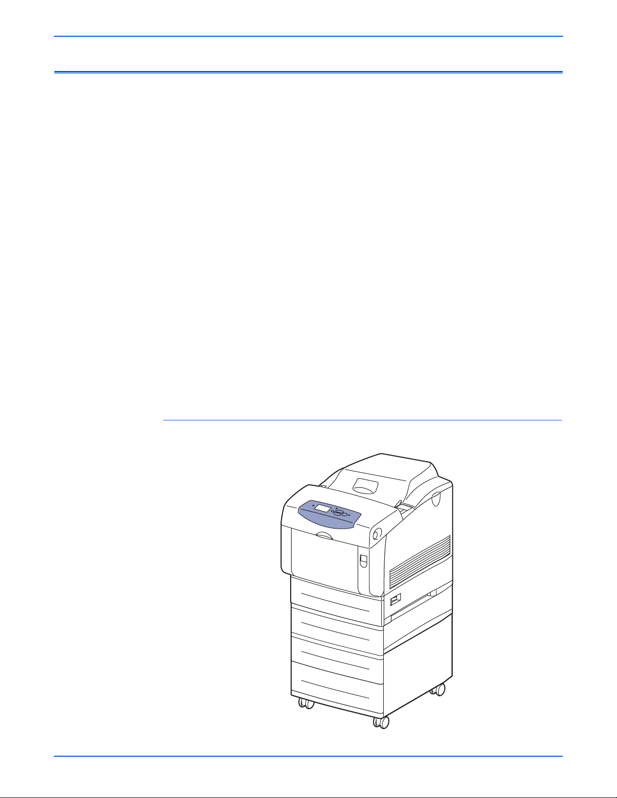
General Information
Printer Introduction and Overview
The Phaser 6300/6350/6360 Color Laser Printer combines a single-pass,
tandem color laser design, with an image processor supporting PostScript 3
and PCL5c page description languages. The printer is a high performance,
Letter or A4, 25 (Phaser
per minute (ppm), desktop color laser printer supporting resolutions up to
2400 x 600 dots-per-inch (dpi). The printer features USB and 10/100baseT
Ethernet ports. The Phaser 6300/6350/6360 printer provides a 150-sheet
Tray 1 (MPT) from which specialty media, card stock, and envelopes are fed.
Tray 1 (MPT) also supports manual feeding. An additional tray, Tray 2 provides
550 sheets of capacity. The Output Tray holds 250 sheets facedown.
Phaser 6300/6350/6360 printer options add memory, paper capacity and
functionality. For configurations not originally equipped, an internal Hard Drive
is available for font storage, storing print files, job collation, proof, personal,
and secure print support. A selection of RAM memory upgrades are available
to raise the installed quantity to the 1 GB maximum. A 1100-Sheet Feeder is
available with two, 550-sheet universal trays. A 550-Sheet Feeder (Tray 3) is
also available. However, the installation of two 550-Sheet feeders is not
supported. One 1100-Sheet and one 550-Sheet feeder is the maximum
configuration. A Configuration Card enables Auto-duplexing (2-sided) printing.
6300), 36 (Phaser 6350) or 42 (Phaser 6360) page
Caution
Several electrical, chassis, and xerographic parts are unique to the 6360
model. When ordering or installing replacement parts, use the Parts Lists
in Section 9 to find the correct part number for the model being repaired.
Phaser 6360 Printer with Optional 550- and 1100-Sheet Feeders
s6360-011
1-2 Phaser 6300/6350/6360 Color Laser Printer Service Manual
Page 23

Printer Configurations
The Phaser 6300/6350/6360 printer is available in five configurations. The
main differences are standard memory, optional high-capacity feeders,
duplexing (2-sided printing) capabilities, and optional internal hard drive. The
following table lists the available configurations.
Features
6300N/
6360N
Printer Configuration
6300DN/
6360DN 6350DP
General Information
6350DT/
6360DT
6350DX/
6360DX
Max Print Speed
(ppm) color/
26/36
42/42
26/36
42/42
36/36 36/36
42/42
36/36
42/42
mono
Hard Drive Optional Optional Optional Optional Yes
Standard
256 MB 256 MB 256 MB 512 MB 512 MB
Memory*
USB Port Yes Yes Yes Yes Yes
10/100 Ethernet Yes Yes Yes Yes Yes
RAM Collation Yes Yes Yes Yes Yes
Duplex Unit No Yes Yes Yes Yes
PostScript and
Yes Yes Yes Yes Yes
PCL Fonts
Banner Sizes Yes Yes Yes Yes Yes
Photo Mode** Yes/
No
Yes/
No
Yes Yes/
No
Yes/
No
Resolutions
(dpi):
Standard
Enhanced
Photo**
1200x600
2400x600
1200x1200
1200x600
2400x600
1200x1200
1200x600
2400x600
1200x1200
1200x600
2400x600
1200x1200
1200x600
2400x600
1200x1200
Tray 1 (MPT) Yes Yes Yes Yes Yes
Tray 2 Yes Yes Yes Yes Yes
550-Sheet
Optional Optional Optional Yes Optional
Feeder***
1100-Sheet
Optional Optional Optional Optional Yes
Feeder***
* All configurations have two memory slots supporting 256 MB and 512 MB cards, to a
maximum of 1 GB.
** Photo Mode not available on Phaser 6360
***Trays 1 and 2 are standard on all configurations. All configurations support additional
paper trays in the following combinations:
One 550-sheet feeder (Tray 3)
One 1100-sheet high-capacity feeder (Trays 3 and 4 or 4 and 5)
One 550-sheet feeder (Tray 3) and one 1100-sheet feeder (Trays 4 and 5)
Phaser 6300/6350/6360 Color Laser Printer Service Manual 1-3
Page 24

General Information
Not
Not
Metered Printing
Metered printing (PagePack), involves the combination of control software and
specialized Toner Cartridges to meter printer activity for billing purposes. The
Configuration page lists Metered Toner as Enabled when metering is enabled.
Metered Operation
When a metered printer is initialized at first power-up, the customer sets the
printer to Metered operation using a unique, factory-supplied, 4-digit PIN. The
customer may use the Control Panel or SNMP to set the PIN. Once set to
Metered operation, the control software performs the following:
1. The Mode and PIN-entered values in Engine Control Board NVRAM are
set.
2. The Control Panel momentarily displays “Metered Toner is now enabled”,
then returns to “Ready” (if no other errors).
3. The First Time Tips pages and the Configuration page are printed.
If an incorrect PIN is entered, “Incorrect Numeric Password, n Retries
Remaining” displays with a prompt “Retry” or “Do not retry.” Retry returns to
the enter prompt, “Do not retry” returns to the Replace [C][M][Y][K] Toner
Cartridge error message.
For 6360 models, the customer is allowed five attempts to set the correct PIN.
After the fifth unsuccessful attempt, the message “Password Entry is Locked”
is displayed. PIN entry remains locked for 24 hours. The lock persists until the
correct PIN is entered.
e
The Hidden Service menu provides an Enable Metered Toner option to
restore the Metered mode parameters to NVRAM should they become
lost or corrupt.
Metered Toner Cartridges
To support metered printing, metered Toner Cartridges are available in all four
colors. When a metered Toner Cartridge is installed in a printer not set for
Metered operation, the printer displays the “Replace [C][M][Y][K] Toner
Cartridge” error. If a metered Toner Cartridge is placed into a printer
manufactured before metering was available, the printer displays “Replace
Incorrect Toner Cartridge.” All other combinations of normal or metered printer
and cartridges are accepted without warning or error.
e
Metered Toner Cartridges for 6360 models are keyed differently from
those available for 6300/6350 models. Toner Cartridges are not
interchangeable.
1-4 Phaser 6300/6350/6360 Color Laser Printer Service Manual
Page 25

Diagnostics Mode
Not
Parts of the Printer
General Information
Service Diagnostics does not provide the utilities to set or clear Metered
NVRAM values. Service Diagnostics does not check these values and does
not display the current status of these values. However, the Configuration
page does identify the printer setting as mentioned above.
e
When replacing the Engine Control Board from a metered printer,
exchange NVRAM devices or use the Save/Restore utilities in Service
Diagnostics to preserve the NVRAM settings. The Mode and PIN-entered
values are not affected by NVRAM reset utilities.
1
2
7
3
8
4
9
5
6
s6360-099
1. Top Cover (Output Tray) 6. Optional Feeders (Tray 3 / Tray 4 and 5)
2. Control Panel 7. Door B Latch
3. Front Cover 8. Door A Latch
4. Tray 1 (MPT) Latch 9. Power Switch
5. Tray 2 (Universal Paper Tray)
Phaser 6300/6350/6360 Color Laser Printer Service Manual 1-5
Page 26
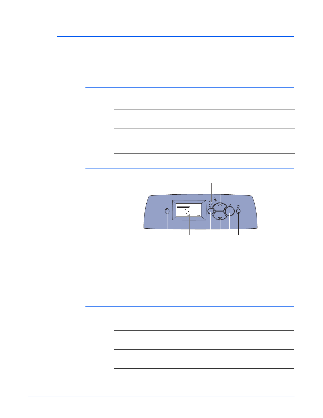
General Information
Control Panel
The Control Panel contains one tricolor LED, a display window, and six
function buttons. These buttons navigate the menu system shown in the
display window, perform various functions, and select modes of operation for
the printer.
LED Indicators:
LED State Printer State
Green Ready to Print
Flashing Yellow Warning (but can still print)
Flashing Green In Power Saver mode or busy (receiving or
processing data)
Flashing Red Error; cannot print
Control Panel Button Descriptions
1 LED (Power/Status) 5 Up Arrow Button - scrolls up the menu
2
Control Panel Display 6 Down Arrow Button - scrolls down the
3 Cancel Button 7 OK (select) Button
4 Back Button 8 Help (?) Button - for explanation or help
Control Panel Shortcuts
Action Press this at Power On
3
5
READY TO PRINT
Walk-Up Features
Information
Paper Tray Setup
Printer Setup
Troubleshooting
1
CMYK
2
4 687
s6360-013
menu
Skip Execution of POST Diagnostics OK
Print Service Diagnostics Menu Map Help (?)
Reset PostScript NVRAM Back + OK
Password Bypass Up Arrow + Down Arrow
Enter Service Diagnostics Back + Help (?)
1-6 Phaser 6300/6350/6360 Color Laser Printer Service Manual
Page 27
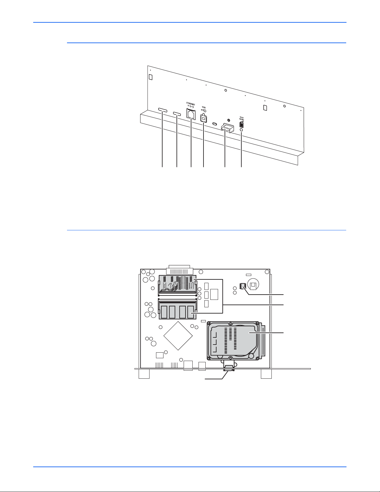
Rear Panel
General Information
s6360-3631 2 3 4 5 6
1. Mode Select Port 4. USB Port
2. Serial Debug Port 5. Configuration Card Port
3. Ethernet Port 6. Test Print Button
Image Processor Board
Transfer the following components, if installed, to the new board when
replacing the Image Processor Board.
Caution
NVRAM
RAM
Hard Drive
Configuration Card
The Image Processor Board used in the 6360 model is unique to that
model. Use care to select the correct replacement part for the model
being repaired.
s6360-380
Phaser 6300/6350/6360 Color Laser Printer Service Manual 1-7
Page 28

General Information
Printer Options
Hard Drive
Phaser 6300/6350/6360 printer options include:
■ Hard Drive
■ Additional Memory
■ Configuration Card
■ 1100-Sheet Feeder
■ 550-Sheet Feeder
Options are common for all models. However, the Configuration Cards are
unique for each model and configuration.
A Hard Drive is available to enable the Job Collation, Saved Jobs, Proof,
Personal, and Secure Print options. The Hard Drive installs on the Image
Processor Board with stand-offs and connects to the board with a single data/
power connector. Hard Drive utilization appears on the Configuration page.
Additional Memory
Configuration Card
The printer features two slots that accept 256 or 512 MB of high-speed DDR
RAM. All combinations are allowed for 256, 512, 768 MB and 1 GB. Memory
modules must have the following characteristics:
■ DDR PC2700 Memory Standard
■ 200-Pin SODIMM
■ Unbuffered, Non-parity
■ Serial Presence Detect
■ 2.5 Volt
■ CL 2.5
The Startup page and the Configuration page list the amount of RAM installed
in the printer. Installed memory not meeting the above specifications, is
ignored by the printer.
A Configuration Card identifies the printer configuration, stores shadowed
non-CRUM consumable data, consumable life counts, and network
configuration parameters.
1-8 Phaser 6300/6350/6360 Color Laser Printer Service Manual
Page 29
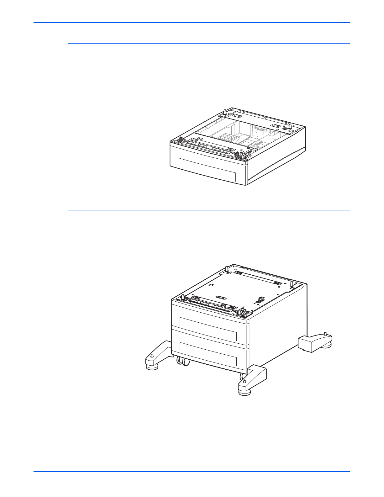
550-Sheet Feeder
General Information
The 550-Sheet Feeder (Tray 3) increases the input capacity of the printer. The
feeder attaches below Tray 2 with four screws. When used in combination with
the 1100-Sheet Feeder, the 550-Sheet Feeder is installed between the printer
and 1100-Sheet Feeder. Only one 550-Sheet Feeders per printer is allowed.
Electrical connection to the printer is made by a single interface connector.
s6360-018
1100-Sheet Feeder
The 1100-Sheet Feeder adds two, 550-sheet trays. Control signals reach the
sheet feeder by a single connection. The sheet feeder is secured to the print
engine or 550-Sheet Feeder with four screws located under the front and rear
edges of the tray.
s6300-019
Phaser 6300/6350/6360 Color Laser Printer Service Manual 1-9
Page 30
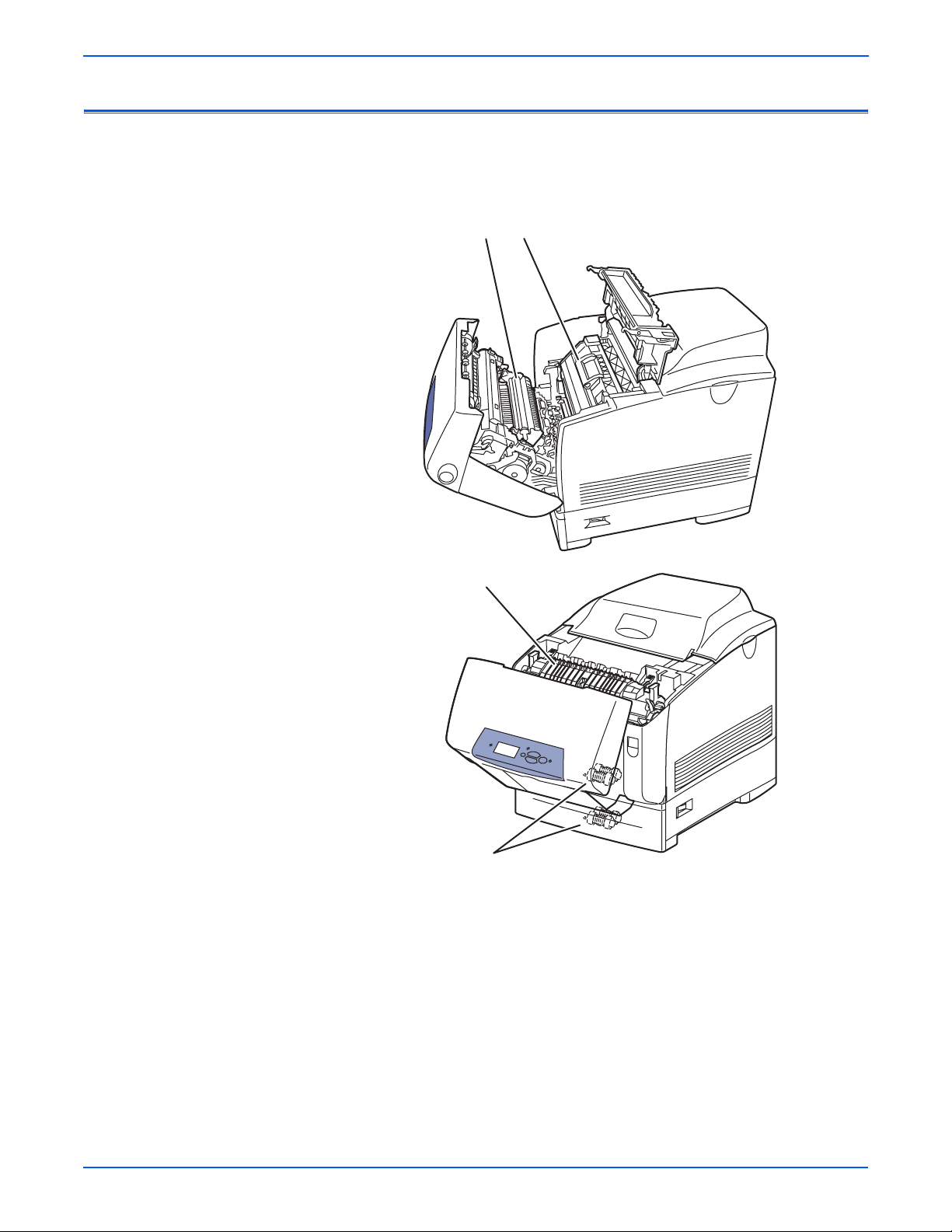
General Information
Not
Maintenance Items
A maintenance item is a printer part or assembly that has a limited life, and
requires periodic replacement.
21
3
4
1. Transfer Roller 3. Fuser
2. Imaging Unit 4. Feed Rollers
e
The 6360 model Fuser is different than the Fuser used in the 6300/6350
models. Also for 6360 models, two Envelope Feed Rollers have been
added to the Tray 1 (MPT) shaft.
s6360-016
1-10 Phaser 6300/6350/6360 Color Laser Printer Service Manual
Page 31

Consumables
Not
General Information
Consumables consist of the four toner cartridges used in the printer. Toner
Cartridges used in the 6360 model are keyed differently from those used in
the 6300/6350 models.
e
Toner Cartridges installed at the time of manufacture contain sufficient
additional toner to prime the Auger Tubes without reducing the 4K life
expectancy. These specialty cartridges are not available as replacement
parts.
s6300-017
Consumable Life Counter Behavior
Internal counters track Consumables and Maintenance Items life usage. The
Image Processor Board monitors these counters in order to display the near
end-of-life and end-of-use messages.
Phaser 6300/6350/6360 Color Laser Printer Service Manual 1-11
Page 32

General Information
Life ratings are based on A-size sheets at 5% coverage. Imaging Unit life
ratings are based on average 5 page job length.
Toner Cartridges Print Life
Specifications
Memory Specifications
Black-Capacity
Color Capacity
Metered (PagePack) Capacity (all colors)
Maintenance Items
Imaging Unit 35,000
Fuser 100,000
Transfer Roller and Waste Box 35,000
Feed Roller Kit up to 100,000
Long-Life Maintenance Kit up to 300,000
Characteristic Specification
Minimum RAM 256 MB
9000 standard, 18,000 high capacity
5000 standard, 12,000 high capacity
18,000 high capacity
Maximum RAM 1 GB
Supported RAM SODIMM 200-pin module of 256 or 512 MB. All combinations are
NVRAM Single chip of either PPROM or StrataFlash 16 MB
Electrical Specifications
Characteristic Specification
Primary line
voltages
Primary line
voltage
frequency
range
In-rush
Current
Power
consumption
at rated
voltage input
allowed for configurations of 256, 512, 768 MB, and 1 GB.
110-127 V Printer - (90 - 135 V) 13 amp circuit
220-240 V Printer - (198 - 254 V) 7-8 amp circuit
100-120 V Printer - 50/60 Hz + 3
Hz
220-240 V Printer - 50/60 Hz + 3
Hz
100A, and 10m sec (half cycle) or less. at rated voltage: ±10%
Mode
Print Mode
Ready Mode
Sleep Mode
Condition
Maximum
Fuser On
Fuser Off
NOTE Power the printer directly
from the wall outlet. Do not
use “Power Strips” as they
may limit available current.
100/120 VAC
1300 W or less
180 W or less
45 W or less
220/240 VAC
1300 W or less
180 W or less
45 W or less
1-12 Phaser 6300/6350/6360 Color Laser Printer Service Manual
Page 33

Physical Dimensions and Clearances
Print Engine Value
Height: 513 mm (20.20 in.)
Width: 429 mm (16.88 in.)
Depth: 580 mm (22.83 in.)
Weight: Approximately 34.6 kg (76.1 lb.) Print engine
1100-Sheet Feeder Value
Height: 341 mm (13.42 in.) Optional Paper Tray Assembly
Width: 429 mm (16.88 in.)
Depth: 509 mm (20.04 in.)
Weight: Approximately 17.6 kg (38.72 lb.)
550-Sheet Feeder Value
Height: 130 mm (5.12 in.) Optional Paper Tray Assembly
Width: 429 mm (16.88 in.)
Depth: 509 mm (20.04 in.)
Weight: 6.3 kg (13.9 lb.)
General Information
Approximately 56.5 kg (124.5 lb.) with Paper Tray(s)
Surface Value
Tilt tolerance: Within 10 mm front to back or 5 mm side to side.
Minimum Clearances
(14 in.)
10 cm
10 cm
(4 in.)
(4 in.)
69 cm
60 cm
(24 in.)
10 cm
(4 in.)
135 cm
(53 in.)
(27 in.)
35 cm
s6360-373
Phaser 6300/6350/6360 Color Laser Printer Service Manual 1-13
Page 34

General Information
Functional Specifications
Functional Specifications
Characteristic Specification
Printing
Process
Imaging System: - 4-tandem drums, electro-photographic system
using intermediate drum transfer rolls (IDTs).
Exposure System: - Semiconductor laser, simultaneous scan by 4
beams.
Development System: - Dry type 2-component developer.
Fusing System: - Heat fusing, free nip-belt system.
Color Medium Yellow, Magenta, Cyan, and Black Toner Cartridges
Resolution /
Addressability
Operating
Modes
Standard
Enhanced
Photo
1200 x 600 dpi (default)
2400 x 600 dpi
1200 x 1200 dpi (not on 6360)
Print Mode: Print Engine capable of making prints immediately.
Ready Mode: 20 seconds from completion of a print.
Sleep/ Low Power/ Power Saver Mode: Entered after a specified
period of inactivity since completion of the last print.
Maximum
Color
Coverage
6300N and DN configurations is 240% at 26 ppm
6350DP, DT, and DX configurations is 200% at 36 ppm
6360 all configurations is 200% at 42 ppm
Print Speed Phaser 6350DP, 6350DT, and 6350DX Configurations
Resolution Letter/A4 Letter/A4 Duplex
Legal Legal Duplex
(ipm)
Standard:
Enhanced:
Photo:
Transparencies
100-163 g/m
163-216 g/m
36/35
26/24
18/18
12
2
18/18
12
2
21/20
15/15
11/11
N/A
11/11
N/A
29
20
12
N/A
12
8
(ipm)
20
13
8
N/A
8
N/A
Print Speed Phaser 6300N and 6300DN Configurations
Resolution Letter/A4 Letter/A4 Duplex
(ipm)
Standard:
Enhanced:
Photo:
Transparencies
100-163 g/m
163-216 g/m
26/24
26/24
18/18
12
2
18/18
12
2
15/15
15/15
11/11
N/A
11/11
N/A
Legal Legal Duplex
(ipm)
20
20
12
N/A
12
8
13
13
8
N/A
8
N/A
1-14 Phaser 6300/6350/6360 Color Laser Printer Service Manual
Page 35

Functional Specifications (Continued)
Characteristic Specification
Print Speed Phaser 6360 All Configurations
General Information
Resolution Letter/A4 Letter/A4 Duplex
Standard:
Enhanced:
Transparencies
100-163 g/m
163-216 g/m
Warm-up Time Less than 45 seconds from cold start (power off condition)
Image Specifications
Characteristic Specification
Maximum Print Area
Guaranteed Print Area
Skew
Registration
Leading Edge
Side Edge
Duplex (front to back)
(ipm)
42/40
36/35
14/13
2
21/20
14/13
2
24.5/24.0
21.3/21.8
N/A
13.5/13.1
N/A
Less than 30 seconds from (standby)
a
210.9 mm (8.3 inches) x 890 mm (35 inches)
b
207.9 mm (8.2 inches) x 347.6 mm (13.7 inches)
± 1.2 mm across 190 mm image
± 2.0 mm
± 2.5 mm
± 4.0 mm
Legal Legal Duplex
(ipm)
33
28
N/A
14
9
23
18
N/A
9
N/A
Parallelism ± 1.2 mm across 234 mm image
Linearity
Vertical
Horizontal
Slant
a. Set margin area within 2.5 mm from each of side edge and 2.0 mm from each of
top/bottom edge.
b. The printer prints images meeting the Print Quality Specification except the margin
area, which is 4.0 mm inside each edge of the paper.
± 0.5 mm across 234 mm image
± 0.5 mm across 190 mm image
± 1.2 mm across 269 mm image
Phaser 6300/6350/6360 Color Laser Printer Service Manual 1-15
Page 36

General Information
Imaging Unit Cleaning Cycle Intervals
Cleaning cycle intervals decrease as the Imaging Unit print volume (life count)
increases. Other factors, such as print mode, environment, temperature,
relative humidity, and area of coverage per print can also increase the
frequency of cleaning cycles irrespective of the Imaging Unit life count.
Cleaning Cycle Interval
Imaging Unit
Print Volume
0 - 5120 108 108 54 39 72 72 52 36 26
5121 - 10240 72 72 36 26 48 48 35 34 17
10241 - 15360 72 72 36 26 48 48 35 34 17
15361 - 20480 72 72 36 26 48 48 35 34 17
20481 - 25600 54 54 27 20 36 36 26 18 13
25601 - 30720 54 54 27 20 36 36 26 18 13
above 30721 54 54 27 20 36 36 26 18 13
a. 42 ppm (6360 standard mode)
b. 36 ppm (6350 standard mode)
c. 26 ppm (6300 standard & Enhanced mode)
d. 18 ppm (Most specialty medias and Photo mode)
e. 12 ppm (Thick Card & envelopes)
Environmental Specifications
Characteristic Specification
42
ppm
B/W Speed Color Speed
36
18
12
42
ppm
ppm
ppm
ppm
36
ppm
26
ppm
18
ppm
12
ppm
Temperature:
Operating
Optimal Print Quality
5o C to 32o C (41o F to 90o F)
15o -28oC (60o to 82o F)
Range
Storage
12 month maximum
48 hours maximum
Normal: 0o C to 35o C (32o F to 95o F), at 15% - 85% RH
Severe: -20o C to 40o C (-4o F to 104o F) at 5% - 95% RH
Humidity (RH)
Operating
Optimal Print Quality
15% - 85% RH
20% to 70% RH
Range
Altitude
Operating
Transportation
Acoustic Noise (Lwa)
Idle
Printing
0 - 3,100 meters (10,170 ft.)
0 - 15,000 meters (30,000 ft.) in pressurized containers.
Printer Only With Feeder Option
5.0 B or less 5.0 B or less
6.65 B or less (Full Speed) 7.35 B or less (Full Speed)
6.65 B or less (Half Speed) 7.30 B or less (Half Speed)
1-16 Phaser 6300/6350/6360 Color Laser Printer Service Manual
Page 37

First Print Output Time
Not
First Print Output Time (FPOT) is defined as a time from receipt of the print
command in Ready mode until the first page sourced from either Tray 1 or
Tray 2 is delivered to the Output Tray. Sourcing media from the optional trays
increases FPOT.
General Information
e
This does not include the execution times for the Boot Loader or POST
which vary depending on printer configuration.
First Print Out Time (seconds)
Process Speed
Simplex
6300-6350 / 6360
Duplex
6300-6350 / 6360
Laser Ready* Laser Off** Laser Ready* Laser Off**
Full 6.0 / 5.4 10.5 / 9.9 10.0 / 8.8 14.5 / 13.3
High 8.0 / 6.0 12.5 / 10.5 13.5 / 10.0 18.0 / 14.5
Mid 10.5 / 9.2 15.0 / 15.0 17.5 / 15.2 22.0 / 22.0
Low 15.0 / 13.2 19.5 / 19.5 25.5 / 21.7 30.0 / 30.0
These conditions apply to the values in the table above:
* At Fuser ready and Laser Unit Motor is rotating normally.
** At Fuser stand-by and Laser Unit Motor Off.
A4 SEF paper
Plain paper mode
Phaser 6300/6350/6360 Color Laser Printer Service Manual 1-17
Page 38

General Information
Media and Tray Specifications
Print the Paper Tips page for a complete listing of supported media types and
sizes.
Media and Tray Specifications
Specification Tray s
Media
Sizes
Media
Types
and
Weights
Paper Type
Letter
Legal
Executive
Statement
US Folio
A4
A5
A6
B5 JIS
ISO B5
Custom Size & Banner
Type
Plain Paper
Heavy Plain Paper
Xerox Premium
Transparency Film (Only)
Thin Card Stock
Thick Card Stock
Labels
Letterhead
Glossy Coated Paper
Digital Photo Paper
Phaser Premium Post-
cards
Pre-printed
Pre-punched
Special
Size
8.5 x 11 in.
8.5 x 14 in.
7.25 x 10.5 in.
5.5 x 8.5 in.
8.5 x 13 in.
210 x 297 mm
148 x 210 mm
105 x 148 mm
182 x 257 mm
176 x 250 mm
8.5 x 36.0 in.
Weight
65 - 90 g/m2 (17 - 24 lb. Bond)
85 - 120 g/m2 (22 - 32 lb. Bond)
100-163 g/m2 (36 - 60 lb.)
160 - 216 g/m2 (59 - 80 lb.)
N/A
85 - 120 g/m2 (22 - 32 lb. Bond)
100 - 163 g/m2 (81 - 110 lb.
Text)
163 g/m2 (60 lb. Cover)
176 g/m2 (65 lb. Cover)
65 - 90 g/m2 (17 - 24 lb. Bond)
65 - 90 g/m2(17 - 24 lb. Bond)
100 - 163 g/m2 (30 - 60 lb.
Cover
All Trays
All Trays
All Trays
All trays
All Trays
All Trays
All Trays
Tray 1 Only
All Trays
Tray 1 Only
Tray 1 Only
All Trays
All Trays
All Trays
All trays
Tray 1 Only
All Trays
All Trays
All Trays
Tray 1 Only
Tray 1 Only
All trays
All trays
All trays
Envelope*Envelopes Weight
Commercial #10
Monarch Envelope
A7 Envelope Custom
DL Envelope
C5 Envelope
C6 Envelope
B5 Envelope
NOTE Do not use envelopes with hot melt glue, windows, or metal
clasps.
20 - 24 lb. Bond
4.12 x 9.5 in.
3.87 x 7.5 in.
5.25 x 7.25 in
110 x 220 mm
162 x 229 mm
114 x 162 mm
175 x 250 mm
Tray 1 Only
1-18 Phaser 6300/6350/6360 Color Laser Printer Service Manual
Page 39

Not
Media and Tray Specifications (Continued)
Specification Trays
General Information
Special
Media
Xerox Premium
Transparencies
Letter
A4
216 x 279 mm (8.5 x 11 in.)
210 x 297 mm (8.27 x 11.69 in.)
All trays
(Other sizes through Tray
1 using custom size
option.)
Phaser Premium
Postcards
Letter
A4
Tray
Capacity*Standard Paper
Transparency
Envelopes
* Some wrinkling and embossing may occur when printing envelopes.
** To avoid Jams be sure to follow the paper weight guidelines for the Universal Tray
capacity: Up to 90 g/m2 paper - load the tray to the top fill line. Between 90 ~ 163
g/m2 - load the tray to the lower fill line only.
216 x 279 mm (8.5 x 11 in.)
210 x 297 mm (8.27 x 11.69 in.)
Universal Tray
550 Sheets
100 Sheets
N/A
Tray 1 Only
Tray 1 Only
Tray 1 MPT
100 Sheets
50 Sheets
10 each
e
For duplex configured printers, auto-duplex operation is available through
all trays. Refer to the Paper Tips page for information on which paper
types can be used for 2-sided printing.
Phaser 6300/6350/6360 Color Laser Printer Service Manual 1-19
Page 40

Theory of Operation
In this chapter...
■ Phaser 6300/6350/6360 Operational Overview
■ Printer Controls
■ Paper Path of the Printer
■ Sensors
■ Print Engine Assemblies
■ 1100-Sheet Feeder Assemblies
■ 550-Sheet Feeder Assemblies
Chapter
2
Page 41

Theory of Operation
Phaser 6300/6350/6360 Operational Overview
The Phaser 6300/6350/6360 Color Laser Printer is a full-color laser printer
that utilizes electrophotographic recording principals to place a full color
image onto the print media. The system, as it appears in the following
illustration, contains a drum and developing unit for each color [yellow,
magenta, cyan and black (YMCK)], and places the toner image of each color
onto print media producing full-color prints through three transfer units
(primary transfer units [IDT1 (2 ea) and secondary transfer unit IDT2 (1 ea)].
Print Process Block Diagram
Drum Y
(1)
(2)
(3)
Intermediate
transfer unit
( IDT1)
Charged
with
electricity
Exposure
Development
(4)
Intermediate
transfer unit
( IDT2)
Paper
Primary transfer
(Drum & IDT1)
(6)
(5)
Secondary transfer
( IDT1
Drum M Drum C Drum K
Charged
with
(1)
electricity
(2)
Exposure
Develop-
(3)
ment
Cleaning
( IDT1)
&
IDT2)
(8)
(7)
Tertiary transfer
( IDT2
&
(9)
Static elimination
Cleaning ( IDT2)
Paper)
(1)
(2)
(3)
Intermediate
transfer unit
( IDT1)
(11)
Charged
with
electricity
Exposure
Development
(4)
Cleaning
(general)
Primary transfer
(Drum & IDT1)
(6)
Transfer Roller
(1)
(2)
(3)
Cleaning
( IDT1)
Charged
with
electricity
Exposure
Development
(10)
Fixing
s6300-020
2-2 Phaser 6300/6350/6360 Color Laser Printer Service Manual
Page 42

Summary of the Printing Process
The printing process is summarized in the following steps. While reading the
summary, refer to the figures on pages 2-2, 2-5, and 2-6. These diagrams
show process flow and indicate the relative position of the components
involved. The diagrams also include reference numbers that correspond to
each numbered step.
1. Charging: The charge roller (RTC) is negatively charged by the High
Voltage Power Supply (HVPS) and is kept in contact with the drum
surface to provide a uniform negative charge on the drum as it rotates at a
constant speed. This occurs simultaneously for YMCK. The refresher is a
conductive brush that is also negatively charged by the HVPS to pick off
any toner particles left on the drum after image transfer to the IDT.
2. Exposure: The Laser Unit uses a system of mirrors and lenses to scan
the drum surface in response to image data from the Image Processor.
Where the laser exposes (writes) the drum surface it reduces the negative
charge to form an invisible latent image. This process is preformed
simultaneously for YMCK.
3. Development: Toner is electrostatically attached to the invisible latent
image on the drum surface to form the visible image on the drum. Toner is
fed into the developer using the agitator in the Toner Cartridge and auger
system in the Toner Cartridge Holder. The toner and the carrier in the
developer form a homogeneous layer on the magnet roller in the
Developer Assembly. The magnet roller turns against the surface of the
drum and is kept at a constant negative potential. At areas on the drum
surface where the negative charge has not been reduced by the impact of
laser light, potential between the drum and the toner particles is lower
than that between the magnet roller and the toner particles. At areas
where the drum charge has been reduced, the potential between the
particles and drum is higher than between the magnet roller and toner
particles are attracted to the drum. A thin semiconducting sleeve on the
magnet roller is vibrated by an AC voltage to encourage migration of the
toner particles to the drum. When the toner particles attach to the drum,
the negative charge of the particles reduces drum potential at that point,
thus reducing the attraction of additional toner particles. This process
occurs simultaneously for YMCK.
The electrostatic characteristics of the carrier deteriorate due to surface
contamination by toner or scratches during agitation. In order to maintain
electrostatic characteristics, a slight amount of carrier is mixed with the
toner in the toner cartridge.The deteriorated carrier is collected in the
Imaging Unit.
Theory of Operation
Phaser 6300/6350/6360 Color Laser Printer Service Manual 2-3
Page 43

Theory of Operation
A
Nozzle
Imaging Unit
Developer
s6360-386
a. The toner and the carrier are moved by the two Augers in the
Developer Assembly.
b. As carrier reaches point A, it’s deposited into the carrier chute.
c. The carrier is then transported toward the Imaging Unit by the nozzle
mounted on the Developer Frame Assembly.
d. The carrier collected in the Imaging Unit is leveled by another Auger
that deposits the carrier at the center of the reservoir.
4. Primary Transfer (drum --> IDT1): The toner image formed on the
individual drum surface is transferred onto the surface of the IDT1
(Intermediate Drum Transfer 1: intermediate transfer roller 1). There are
two IDT1’s: one for yellow and magenta and one for cyan and black. IDT1
is conductive and receives a high positive charge from the HVPS. The
negatively charged toner image on the drum surface is attracted by the
high positive potential and transfers to IDT1. During this transfer, the
remaining negative charge on the drum is neutralized by the high positive
charge on IDT1.
5. Secondary Transfer (IDT1 --> IDT2): The toner images formed on both
IDT1 surfaces are then transferred onto the surface of IDT 2 to create a
complete, 4-color toner image. IDT2 is biased at a higher positive
potential than IDT1 thus attracting the toner image and transferring it from
IDT1 to IDT2.
6. Cleaning: The IDT1 cleaner consists of a conductive roller brush rotating
in contact with IDT1 after the point where the toner is transferred to IDT2.
The cleaner receives a high positive voltage from the HVPS allowing it to
electrically attract any toner particles remaining on IDT1. Toner remaining
on both IDT1’s after the image transfer to IDT2 is temporarily stored in the
IDT1 cleaners.
7. Tertiary Transfer: The finished toner image on IDT2 is transferred onto
the print media using the biasing charges supplied by the Transfer Roller.
The conductive Transfer Roller receives a high positive voltage from the
HVPS that puts it at a higher potential than IDT2. Since the Transfer
Roller is located behind the print media, the 4-color toner image is
attracted to the high potential and transfers to the surface of the print
media.
2-4 Phaser 6300/6350/6360 Color Laser Printer Service Manual
Page 44

Theory of Operation
8. Cleaning: The IDT2 cleaner consists of a conductive roller brush rotating
in contact with IDT2 after the point where the toner is transferred to the
print media. The cleaner receives a high positive voltage from the HVPS
allowing it to electrically attract any toner particles remaining on IDT2.
Toner remaining on IDT 2 after the image transfer to the print media is
temporarily stored in the IDT2 cleaner.
9. Static Elimination: The positive charge on the print media can cause
image quality problems by scattering toner. To prevent this, negative DC
voltage from the HVPS is applied to the back side of the print media by
the Detack Saw, located on the Transfer Roller. This negative charge
neutralizes and eliminates the static charge on the print media resulting
from the tertiary transfer.
10. Fixing: The initial image is unstable and easily smeared. To fix the image,
the print media goes through the Fuser where it passes between a
pressure belt and the heat roller. The toner is fused onto the print media
by the combination of heat and pressure.
11. Cleaning: During the general cleaning process, the voltage applied to the
IDT rollers and drums go through a cycle of changes to move the negative
and positive charged toner particles from the cleaners and IDTs and then
the Transfer Roller. The toner stored in the IDT1 cleaner, the IDT 2
cleaner is removed and deposited into the Imaging Unit waste toner
reservoir. Toner from the Transfer Roller, charge roller and refresher is
also removed and deposited into the Transfer Roller waste toner reservoir.
In each case the voltage at the point of attraction is set high and the
voltage at the point of disposal is set to 0V with the result that the toner is
moved to the high potential until at last it is deposited on the Transfer
Roller. Toner is removed from the Transfer Roller by the attached cleaning
blade and deposited in the attached waste toner reservoir.
Print Process Components
The relative position of the components involved in the printing process, the
tray and duplex paper paths, and numbered references to the “Print Process
Block Diagram” on page 2-2, appear in the following figure.
Y Toner Cartridge
[(3) Development]
M Toner Cartridge
[(3) Development]
C Toner Cartridge
[(3) Development]
K Toner Cartridge
[(3) Development]
: Laser beam
: Paper transfer
Laser Unit [(2) Exposure]
Developer Frame Assembly
Imaging Unit
Fuser
[(10) Fixing]
Transfer Roller
[(7) Tertiary transfer]
[(11) Cleaning]
s6300-021
Phaser 6300/6350/6360 Color Laser Printer Service Manual 2-5
Page 45

Theory of Operation
2
The Developer Frame Assembly, Imaging Unit, and numbered references to
the
“Print Process Block Diagram” on page 2-2, are detailed in the following
figure.
Developer Frame Assembly Imaging Unit
Drum (Y)
Drum (M)
IDT1
[(4) Primary transfer]
[(5) Secondary transfer]
IDT2 Cleaner [(8) Cleaning]
IDT1 Cleaner [(6) Cleaning]
IDT2
Developer
[(3) Development]
[(5) Primary transfer]
[(7) Secondary transfer]
Drum (C)
IDT1
[(4) Primary transfer]
[(5) Secondary transfer]
Print-Quality Modes
IDT1 Cleaner [(6) Cleaning]
:Refresher
Drum (K)
:RTC [(1) Changing
with electricity]
s6300-02
There are four print-quality modes on the 6300 and 6350, three on the 6360:
Print-Quality Mode Description
Automatic Automatically selects the optimal print-quality mode for the
paper type selected. For example, Photo print-quality mode is
used when printing on Glossy Paper and Standard printquality mode is used when printing on Plain Paper. (This
setting is only available in the printer driver.)
Standard 1200 X 600 dpi resolution. High-speed, general-purpose mode
for crisp, bright, color prints. Recommended for most office
use and quick prints.
Enhanced 2400 X 600 dpi resolution. High-quality mode for fine lines and
detail. Recommended for vibrant, saturated, color prints.
Balances printing speed with quality.
Photo
(Not on 6360)
1200 X 1200 dpi resolution. Highest-quality mode for color
prints and smoothest light colors. Recommended for
photographs, smooth shaded drawings, and vibrant color.
:
2-6 Phaser 6300/6350/6360 Color Laser Printer Service Manual
Page 46

Printer Controls
Not
Paper Size Control
Theory of Operation
The paper size detection for Trays 2, 3, 4, and 5 is determined by the Paper
Size Switch, composed of three microswitches, located in each paper tray
slot. The switch condition is set by moving the paper guide in the tray. This in
turn sets the plastic actuators on the side of the paper tray to a specific
position that activates the switch combination indicating the media size.
Paper Size Switches Indicated as SW1, SW2, and SW3
SW 1
SW 2
SW 3
Selective Control; Paper Pick
Unless changed in printer setup, the default tray is Tray 2. Trays in the optional
1100-Sheet Feeder are identified as Tray 3 and Tray 4. The tray in the optional
550-Sheet Feeder is identified as Tray 3. If both optional Feeders are
installed, the 550-Sheet Feeder tray is identified as Tray 3, and the trays of the
1100-Sheet Feeder are identified as Tray 4 and Tray 5.
e
The Phaser 6300/6350/6360 printer supports the installation of only one
550-Sheet Feeder. Attempting to install a second results in an
unsupported configuration error.
s6360-385
Paper Size
Paper Size Switch
SW1 SW2 SW3
Legal 14" On On On
US Folio (Legal 13") On On Off
Executive On Off On
B5 On Off Off
A4 Off On On
A5 (Tray 1(MPT) only) Off On Off
Letter Off Off On
No Tray Off Off Off
Laser Light Intensity Control
The Laser Unit in the Phaser 6300/6350/6360 printer has four laser diodes:
one each for yellow, magenta, cyan, and black. The diode control circuitry
adjusts the light intensity for each color automatically. Image data is
transmitted to the laser diodes in the Laser Unit as digital signals. The laser
diodes convert the image data from digital signals to optical signals. The
Laser Unit monitors and adjusts the intensity of the laser beams to attain a
stable electrostatic image.
Phaser 6300/6350/6360 Color Laser Printer Service Manual 2-7
Page 47

Theory of Operation
The data path of image data is shown in the following figure.
Host (Electric Signal)
Printer Controller (Electric Signal)
Engine Control Circuit Board (Electric Signal)
Laser Unit (Laser Beams)
Electrostatic Latent On Drum
(Invisible Image)
Toner Image On Drum
Process Control
Toner Image On Intermediate Transfer Unit
(IDT1)
Toner Image On Intermediate Transfer Unit
(IDT2)
Toner Image On Paper
Print Image On Paper
s6300-043
For stable printing, the parameters related to forming both the electrostatic
and toner image are continuously monitored and adjusted by the printer.
Parameter correction and control over the entire printing process is called
“process control”. There are two main areas of control:
■ Bias Control
■ Toner Density Control
To supplement these two controls, the following are provided:
■ High-Area Coverage Mode Control
■ Admix Mode Control
■ Toner Density Control (CTD) Sensor (ADC - Automatic Density Control)
LED light density setting.
2-8 Phaser 6300/6350/6360 Color Laser Printer Service Manual
Page 48

Bias Control
Theory of Operation
To attain stable image density, toner density is monitored for each color and
the drum charging voltage and biasing DC voltages are adjusted accordingly.
The bias control adjustment is made immediately before the start of printing, if
any of the following conditions is satisfied:
■ First print produced after the power on.
■ Cumulative print count exceeds 16 since power on.
■ A cleaning cycle is executed during continuous printing.
Bias control operates as follows:
1. The Temperature/Humidity Sensor provides input to establish target
values of the drum charging voltage and biasing DC voltage.
2. Bias control test patches (see the adjacent
About 11 mm
figure for patch configuration) of each of the
four toner colors (yellow, magenta, cyan, and
Y
black) are generated and transferred to the
About 12 mm
Transfer Roller.
3. The CTD (ADC) Sensor compares an area on
the Transfer Roller where no toner is present
M
About 3 mm
About 57 mm
with the test patches to determine toner
density for each of the four colors.
C
4. The density measured in Step 3 is compared
with the target value set in Step 1 and the
resulting difference is used to adjust the drum
charging voltage and the biasing DC voltage
K
s6360-066
for each toner color.
Toner Density Control
Toner density is kept constant to maintain a stable print image. To achieve
this, the rate at which toner is dispensed is adjusted to exactly match the rate
at which it is consumed. There are two systems that work together to control
toner density: the Pixel Count Dispense Control (PCDC) and the Toner
Density Control (CTD). (The CTD uses data from the ADC sensor, measured
as described in the preceding paragraphs covering bias control.)
PCDC: The amount of toner consumed in the developing process is
determined by counting the digital pulses applied to the Laser Unit as part of
the Image data transfer. Based on this count, the toner motor is driven to
dispense an equivalent amount of toner to compensate for the loss.
CTD (ADC): Toner test patches of each color (yellow, magenta, cyan, and
black), are generated and applied to the Transfer Roller as described in the
Bias Control discussion. The CTD (ADC) Sensor is used to measure the
density of each patch. The CTD (ADC) Sensor signal indicates how much to
adjust the toner dispense time (Toner Motor rotation) for each color. The CTD
adjustment is made following completion of printing under either the following
conditions:
■ Cumulative print count since power on exceeds 16 pages.
■ When a cleaning cycle is executed during continuous printing.
If an adjustment to the toner quantity is necessary, a Dispense Count is
calculated and executed as a specific number of Toner Motor rotations.
Phaser 6300/6350/6360 Color Laser Printer Service Manual 2-9
Page 49

Theory of Operation
The Dispense Count is implemented over the next eight prints. For example, if
the Dispense Count is 16, two dispense counts are added during each of the
next eight prints. This is in addition to any counts added or subtracted during
each print as a result of PCDC.
If the CTD (ADC) Sensor indicates that toner density is too high and that 16
Dispense Counts are required to return toner density to normal, the
adjustment is accomplished by subtracting two counts from the calculated
PCDC count over each of the next eight prints. If the excess amount cannot
be subtracted in 8 print cycles, it is subtracted in the ninth and subsequent
prints. The following figure illustrates this process.
Total Dispense Counts
Correction Amount By ADC +16
Dispense Counts By PCDC
Correction Amount By ADC -8
Total Dispense Counts
High Area Coverage Mode
The High Area Coverage mode delays page feeding giving the printer
additional time to dispense toner. This mode compensates for images whose
toner density exceeds the printer’s toner dispense capabilities. This typically
occurs during continuous runs of images that drop the toner density for any
color Developer below the reference value.
Admix Mode
If High Area Coverage mode fails to compensate for the reduction in
Developer toner density, or if the printer is moved to an environment with a
different humidity level changing the reference value, Admix mode dispenses
toner immediately to restore toner density levels if needed.
4534223432
Even Allotment In First 8 Prints
2 3 1 2 0 0 1 2 3 2
1201000022
s6360-067
2-10 Phaser 6300/6350/6360 Color Laser Printer Service Manual
Page 50

LED Light Density CTD (ADC) Control Sensor
The CTD (ADC) Sensor is a photo-reflective sensor that emits light from an
LED and detects the reflected light returning from the Transfer Roller. The
CTD (ADC) Sensor reference voltage (reflected light density) is established
when both the sensor and the Transfer Roller are clean and free of defects.
The light emitted from the LED is controlled so that the reflected light density
meets the reference value.
LED light emission control is implemented in two ways:
■ Sets the light density so that the light reflected satisfies a specific
value.
■ Adjusts the subsequent light density to be within a specific tolerance
value.
1. Light Density Setting
The reflected light density can vary greatly if the Transfer Roller has just been
replaced or the CTD (ADC) Sensor has just been cleaned, or is dusty with
waste toner. To compensate with this variance, the light density is reset each
time the power is turned on or a door is opened.
When the output of the CTD (ADC) Sensor does not meet the reference
value, the intensity of the LED light emissions are increased gradually and the
Light Density Setting is adjusted. If the light density is increased to the
maximum and output of the CTD (ADC) Sensor does not reach the reference
value, a warning message indicates the sensor is dirty. If the sensor output
remains above the reference value, a fatal error reports that the sensor is
faulty.
Theory of Operation
2. Light Density Adjustment
At the execution of Automatic Density Control, the Light Density Adjustment is
made just before the toner patches for toner density control are generated.
Light is emitted from the LED using the current Light Density Setting, to check
if the output value of the CTD (ADC) Sensor is within the specified range. If
the output value is low, light density is increased. If the output value is high,
light density is decreased.
If the output value is less than the first lower limit, a warning message
indicates the sensor is dirty. If the output value is less than the second lower
limit, a Fatal Error signals that the sensor is faulty and the printer stops
printing.
Phaser 6300/6350/6360 Color Laser Printer Service Manual 2-11
Page 51

Theory of Operation
Color Registration Control
The printer uses a quad system where drums and developers are used
exclusively for each of the four colors (yellow, magenta, cyan, and black).
Images are formed on the drums, in the respective colors, and then layered to
form one image. To avoid a positional shift between the different color images,
the color registration control calculates how much the registration has shifted
by comparing each of the other color patches in the registration string to the
black bar that precedes it. Shift is corrected by adjusting the laser write timing
to compensate.
Color registration control is made depending on the internal temperature and
print count at the execution of process control.
This control is outlined below:
1. With no toner on the Transfer Roller, the output value of the CTD (ADC)
Sensor is measured to determine the reference value.
2. Patches for color registration control are
generated on the Transfer Roller. These
patches are composed of 10 mm lines
of each toner color in the following
order: K, C, K, M, K. The string of
patches is led by a black trigger patch
that is larger than the registration
patches.
3. The density of patches generated is
measured by the CTD (ADC) Sensor.
About One Turn
Of Transfer Roller
10 mm
K
K
C
K
M
K
Y
4. The amount of registration shift is
calculated from the reference value
determined in Step 1 and the patch
density measured in Step 3.
5. The laser write timing is changed to
s6360-068
compensate for any registration shift.
2-12 Phaser 6300/6350/6360 Color Laser Printer Service Manual
Page 52

Transfer Roller Control
Detecting the Transfer Roller
The CTD (ADC) Sensor is used to detect the presence of the Transfer Roller.
This determination is made whenever power is turned on, or a door is opened
and closed.
If the output of the CTD (ADC) Sensor is greater than the reference value the
controller signals that the Transfer Roller is present. If the sensor output is
lower than the reference, a Fatal Error indicates that the Transfer Roller is not
installed.
If printing is stopped by a jam, a latent image remains on the Transfer Roller.
To prevent a false error, the controller rotates the Transfer Roller a half turn. If
the sensor output remains below the reference, a Transfer Roller missing error
is generated. Otherwise, the sensor output indicates that the Transfer Roller is
present and no additional error is reported.
Detecting Transfer Roller Life
Theory of Operation
The Transfer Roller consists of a bias transfer roller and a waste toner
recovery space. Transfer Roller end of life occurs when the Toner Full Sensor
detects that the waste toner recovery space is full.
1. Status of the waste toner reservoir is checked:
a. When the power is turned on.
b. When a door is opened and closed.
c. When paper exits the print engine.
2. Transfer Roller is at End of Life warning message is generated when the
Toner Full Sensor detects the waste toner reservoir is full.
3. Replace Transfer Roller error message is generated if the print count and
the toner dispense time are counted and the total count exceeds 15,000
prints.
4. Transfer Roller is at End of Life warning and Replace Transfer Roller error
messages are reset if the Toner Full Sensor does not detect a full waste
toner reservoir when power is turned on, or a door is opened and closed.
Phaser 6300/6350/6360 Color Laser Printer Service Manual 2-13
Page 53

Theory of Operation
Toner Control
Toner Cartridge presence is detected by a combination of the Toner Sensor
Actuator and CRUM Reader. Presence of toner in the cartridge is detected by
the No Toner Sensor. These sensors are provided for each toner color
(CMYK), and detection is made for each individually.
No Toner Sensor
The No Toner Sensor located on each Toner Cartridge Holder checks one
color every 3.5 seconds, requiring 14 seconds to detect all four colors. The
sensor detects toner as it’s dispensed from the toner cartridge into the auger
tube.
To prevent false errors resulting from toner obscuring the sensor, a film
attached near the auger in the Toner Cartridge Holder cleans the sensor
surface whenever toner is dispensed. False errors related to toner detection
are avoided by the printer’s internal Toner Presence Control.
Toner Presence Control
1. Checks for toner presence when the power is turned on, or after a door is
opened and closed. Checks every 14 seconds when printing.
2. The "Replace [CMYK] Toner Cartridge" error displays when the counter
on the Customer Replaceable Unit Monitor (CRUM) indicates that the
toner is empty.
3. The "Replace Toner Cartridge” error displays when the No Toner Sensor
detects that a cartridge is empty.
4. When a new Toner Cartridge is installed prior to receipt of a "Replace
Toner Cartridge” error, toner is dispensed for 1.7 seconds. At the next
toner presence control sampling, if the No Toner Sensor detects toner
present, all Toner “Warnings", and "Errors" are reset. When toner is
dispensed and the No Toner Sensor detects toner present three or more
times consecutively, the controller regards this status as "Toner Present".
5. If the No Toner Sensor does not detect toner, toner is dispensed for 1.7
seconds again 5 seconds later. If toner present is not detected after
executing toner dispense three times and if Toner Cartridge dispense time
is 0, the “Remove Ribbon From ‘x’ Cartridge” error displays.
2-14 Phaser 6300/6350/6360 Color Laser Printer Service Manual
Page 54

Fuser Control
Fuser Temperature Control
Cool Down
Theory of Operation
During Fuser temperature control the printer’s target temperature is set based
on the media type. The Heat Roller surface temperature is controlled to match
the target temperature by turning the heater lamp On and Off.
The Heat Roller surface temperature is detected by two sensors. A NonContact Sensor (NCS) in the middle of the roller and the Temperature Sensor
at the edge of the roller. These sensors are checked every 10 ms to maintain
an even temperature across the Heat Roller. If the readings indicate the
temperature is higher than the target, the heater lamp is turned Off. If the
readings fall below the target temperature, the heater lamp is turned On.
For the target temperature, different temperatures are set for standby, printing,
and process control. The target temperature is also changed according to the
inside temperature detected with the Temperature/Humidity Sensor, print
count, print mode, input power supply voltage and paper type.
During printing, the temperature distribution of the Heat Roller becomes
uneven. To compensate, a wait time is provided and the heater lamp is kept
Off. When Heat Roller temperature stabilizes, printing resumes.
Phaser 6300/6350/6360 Color Laser Printer Service Manual 2-15
Page 55

Theory of Operation
8
Paper Path of the Printer
Paper path components and routing for the printer and the optional 1100Sheet High-Capacity Feeder are shown in the following figure.
: Paper transfer
Exit Roller
Duplex Roller
Transfer Roller
Metal
Registration Roller
Rubber
Registration Roller
Tray 1 Feed Roller
Retard Roller
Feed Roller Assembly
Tray 1 Turn Roller
Feeder Chute
Turn Roller
Retard Roller
Feeder Chute
Turn Roller
Retard Roller
Feeder Chute
Turn Roller
Retard Roller
s6360-07
2-16 Phaser 6300/6350/6360 Color Laser Printer Service Manual
Page 56

Paper Path Route
Theory of Operation
Paper Feed From Tray 4
Paper Feed By
"Tray 4 Feed Roller"
Paper Feed By
"Roller Assy"
And
"Tray 4 Feed Roller"
Paper Transfer By
"Tray 4 Turn Roller"
And
"Tray 4 Turn Chute"
Paper Transfer By "Tray 3 Turn Roller"
And "Tray 3 Feeder Chute Assembly"
Paper Transfer By "Turn Roller" And "Feeder Chute"
Paper Transfer By "Rubber Regi Roller" And "Metal Regi Roller" Of Registration Chute Assembly
Paper Feed From Tray 3 Paper Feed From Tray 2 Paper Feed From Tray 1
Paper Feed By
"Tray 3 Feed Roller"
Paper Feed By
"Roller Assy"
And
"Tray 3 Feed Roller"
Paper Transfer By "Tray 1 Turn Roller" And "Turn Pinch Roller"
Paper Transfer By "IDT2" Of Imaging Unit And "Transfer Roller"
Paper Feed By
"Tray 2 Feed Roller"
Paper Feed By
"Roller Assy"
And
"Tray 2 Feed Roller"
Paper Feed By
"Tray 1 Feed Roller"
And
"Retard Roller"
Paper Transfer By "Heat Roller" And "Fuser Belt"
Paper Transfer By "Exit Roller Assembly" And "Fuser Pinch Roller"
Paper Transfer By "Exit Roller" And "Exit Pinch Roller" Of Chute Assembly Out
Print Output
Paper Transfer To Duplex Path
By Reversing "Exit Roller"
Paper Transfer By "Duplex Roller"
And "Duplex Pinch Roller"
s6360-077
Phaser 6300/6350/6360 Color Laser Printer Service Manual 2-17
Page 57

Theory of Operation
Sensors
Sensor Types
The printer contains sensors of various types that perform a variety of
functions. One group of sensors track the progress of the paper along the
paper path, and detects if a paper jam occurs. Other sensors detect the
presence of the Toner Cartridges, stop printer activity if a door is open
(interlock), detect the presence and size of media in the trays, and monitor the
fusing temperature.
The types of sensors used vary with function. In general, there are three types
in use:
Photo Sensors
Two types of photo sensors are used, photo-reflective and photo-receptive.
Photo-reflective sensors use light reflected back from an object to detect its
presence. Photo-receptive sensors use an actuator or the object itself to block
the light path to detect an object or condition.
Photo-reflective sensors have the light emitter and light receiver aligned on a
single surface. Output of the photo-receptor is High (> +4.5 V) when light is
being reflected back and Low (< +.3 V) when it isn’t. Photo-receptive sensors
consist of a LED in one arm of a U-shaped holder, and a photo-transistor in
the other arm. When the sensing area is vacant, nothing is between the arms
of the sensor, light falls on the photo-receptor sending the signal High. If the
light is interrupted, the photo-transistor goes Low.
Microswitches
Microswitches are used primarily as paper size sensors and cover interlocks.
They are in a normally open state, and close when actuated. A bank of
microswitches is used to detect paper size in the universal trays.
Microswitches also employ hooks or catches for retention in the bracket or
frame.
Thermistors
Thermistors have a known value of resistance whose value varies with
temperature. Used primarily in the Fuser for temperature sensing.
2-18 Phaser 6300/6350/6360 Color Laser Printer Service Manual
Page 58

Sensors in the Paper Path
The following illustration identifies the various sensors located along the
paper path. Error reporting is dependent on these designators. Error detection
is based on paper transport timing through the sensing area.
Theory of Operation
Full Stack
Sensor
Fuser Exit
Sensor
Duplex Jam
Sensor
Tray 1 (MPT)
No Paper
Sensor
Registration
Sensor
Paper Size Sensor
Low Paper Sensor
No Paper
Sensor
s6360-340
Phaser 6300/6350/6360 Color Laser Printer Service Manual 2-19
Page 59

Theory of Operation
Paper Path Sensor Locations
The following diagrams show the relative position of sensors located along the
paper path.
Duplex Jam
Sensor
Fuser Exit
Sensor
Full Stack Sensor
Interlock Switch
Registration Sensor
Tray 1 (MPT) No Paper Sensor
No Paper Sensor
Low Paper Sensor
Paper Size Switch
s6360-362
2-20 Phaser 6300/6350/6360 Color Laser Printer Service Manual
Page 60

Xerographic Sensor Locations
The following diagrams show the relative position of xerographic sensors.
CRUM Connector
Theory of Operation
Temperature/Humidity Sensor
Toner Cartridge In Sensor
No Toner Sensors
CTD (ADC) Sensor
Toner Full Sensor
s6360-374
Phaser 6300/6350/6360 Color Laser Printer Service Manual 2-21
Page 61

Theory of Operation
Not
Print Engine Assemblies
Drive Assemblies
The following section describes the major functional components of the print
engine.
e
The drive assemblies used in the 6360 model are different than those
used in the 6300/6350 models. Use care when selecting the replacement
part.
Developer Drive Assembly
Fuser Drive Assembly
■ Developer Drive Assembly
Main Drive Assembly
s6360-064
Drives the Developer Frame Assembly.
■ Main Drive Assembly
Drives the following parts:
■ Paper Pick Assembly
■ Chute Assembly Out (MPT position)
■ Registration Roller Assembly
■ Tray 1 (MPT) Retard Roller
■ Imaging Unit
■ Transfer Roller
■ Fuser Drive Assembly
Drives the Fuser Assembly.
2-22 Phaser 6300/6350/6360 Color Laser Printer Service Manual
Page 62

Developer Drive Assembly
The Developer Drive Motor drives the four developers housed in the
Developer Unit. The drive transmission route differs depending on the print
mode. For monochrome printing, the developer for the K drum is activated as
shown in the following figure.
Developer Drive Motor
Gear D5 (1 Way Clutch)
Theory of Operation
Gear D2-IN
Gear D7
Gear D8
Gear Developer Input (K)
Mag Roll (K)
Deve Assy (K)
s6360-342
Phaser 6300/6350/6360 Color Laser Printer Service Manual 2-23
Page 63

Theory of Operation
The following figure shows the relative positions of the gears being driven
during monochrome printing.
Developer
Drive Motor
Drive Motor
Gear
Gear D2-In
Gear D8
Gear Developer
Input (K)
Gear D7
Gear D5
Front
s6360-052
2-24 Phaser 6300/6350/6360 Color Laser Printer Service Manual
Page 64

Theory of Operation
When printing in full color, the Developer Drive Assembly uses a series of
gears to drive all four developers to support the Y, M, C, and K drums. The
following figure diagrams the transmission path of the Developer Drive
Assembly in full color printing.
Developer Drive Motor
Gear D2-In
Gear D2-Out
Gear D3 (1 Way Clutch)
Gear D6
Gear D8
Gear Deve Input (Y)
Mag Roller (Y)
Developer Assy (Y)
Gear D4 (1 Way Clutch)
Gear D6
Gear D8
Gear Deve Input (M)
Mag Roller (M)
Developer Assy (M)
Gear D8
Gear Deve Input (C)
Mag Roller (C)
Developer Assy (C)
Gear D5
(1 Way Clutch)
Gear D7
Gear D8
Gear Deve Input (K)
Mag Roller (K)
Developer Assy (K)
s6300-045
Phaser 6300/6350/6360 Color Laser Printer Service Manual 2-25
Page 65

Theory of Operation
The following figure shows the relative positions of the gears being driven
during full color printing.
Full Color Mode
Gear D8
Gear Developer
Input (Y)
Gear D8
Gear Developer
Input (M)
Gear D8
Gear Developer
Input (C)
Gear D8
Gear Developer
Input (K)
Gear D7
Gear D6
Gear D6
Gear D4
Developer
Drive Motor
Drive Motor
Gear
Gear D3
Gear D2-In
Gear D2-Out
Gear D5
Front
s6360-053
2-26 Phaser 6300/6350/6360 Color Laser Printer Service Manual
Page 66

Main Drive Assembly
The Main Drive Motor drives the Imaging Unit, Transfer Roller, Registration
Chute, and paper feed. The following figure diagrams the relationship of the
Main Drive Motor, the gear set, and printer functions.
Theory of Operation
Main Drive Assembly
Gear Idler In
Gear Idler Feed Tray 1(MPT) Turn Roller
Registration Clutch
Rubber Regi Roller
Metal Regi RollerGear Feed 2
Feed Roller Assembly
Gear Feed H2
Registration Chute Assembly
Gear Idler Turn
Gear Feed H1
Gear Feed 2
Feed Roller Assembly
Turn Roller Assembly
Roller Assembly
Paper Feeder
Gear (MPT)
Turn Clutch
Gear P1
Gear Turn
IDT2
Feed Roller Assembly
IDT1 (2)
Chute Assembly Out
Drum (4)
Retard Roller
Imaging Unit
Transfer Roller
s6300-044
Phaser 6300/6350/6360 Color Laser Printer Service Manual 2-27
Page 67

Theory of Operation
The following figure shows the location of the various components driven by
the Main Drive Assembly.
Chute Assembly Out
Imaging Unit
Transfer Roller
Tray 1 Gear
Main Drive
Assembly
Retard Roller
Gear Idler In
Gear Idler Feed
/ Gear Feed 2
Paper Pick Assembly
Gear Feed 2
Gear Feed H2
Front
/ Gear Feed H1
s6360-049
A number of other motors are used to drive rollers, move paper, and supply
toner. These motors are described in detail in subsequent sections that
highlight printer function in more detail.
2-28 Phaser 6300/6350/6360 Color Laser Printer Service Manual
Page 68

Fuser Drive Assembly
Supplies the drive to the Fuser as shown in the following figure.
Theory of Operation
Fuser Drive Assembly
Heat Roll
Gear Exit
Fuser Exit Roller
Fuser
s6360-343
Phaser 6300/6350/6360 Color Laser Printer Service Manual 2-29
Page 69

Theory of Operation
Not
Registration Roller Assembly
Shown in the following figure are the components associated with aligning the
paper in preparation for image transfer (Registration), and feeding paper from
Tr ay
1 (MPT). The Registration, Turn and Retard rollers are driven by the Main
Drive Motor.
e
The Registration Roller Assembly used in the 6360 model is different than
the roller assembly used in 6300/6350 models. Use care when selecting
the replacement part.
Registration Sensor
Metal Registration Roller
Rubber Registration Roller
Retard Roller Assembly
Registration Clutch
Tray 1 (MPT) Turn Roller
Turn Clutch
■ Registration Sensor
s6360-058
Detects the when the media’s leading edge has reached the Registration
Chute.
■ Rubber Registration Roller
Driven by the Main Drive Assembly through the Registration Clutch, the
2-30 Phaser 6300/6350/6360 Color Laser Printer Service Manual
Page 70

Theory of Operation
Rubber Registration Roller works with the Metal Registration Roller to
correct media skew and transport media.
■ Metal Registration Roller
Works in conjunction with the Rubber Registration Roller. When the
leading edge of the paper arrives at the registration rollers, the rollers are
not turning and the paper buckles against the rollers to correct any skew
at the leading edge.
■ Turn Roller
The Turn Roller is rotated by the Main Drive Assembly, through the Turn
Clutch to feed paper from Tray 1 (MPT) to the Registration Chute.
■ Turn Clutch
Transfers drive from the Main Drive Assembly to the Turn Roller through a
friction clutch.
■ Registration Clutch
Transfers drive from the Main Drive Assembly to the Rubber Registration
Roller, and transports the paper from Tray 1 (MPT) and the duplex path
toward the Imaging Unit.
Main Drive Assembly
Registration Chute Assembly
Gear Turn
Front
Registration Clutch
Gear P1
Turn Clutch
Gear Idler Turn
Paper Pick Assembly
s6360-050
Phaser 6300/6350/6360 Color Laser Printer Service Manual 2-31
Page 71

Theory of Operation
Not
Chute Assembly In
e
The Chute Assembly In used in the 6360 model is different than the
assembly used in 6300/6350 models. However, some sub-components of
the assembly are common for all models. Use care when selecting the
replacement parent assembly or component part.
Fuser
Toner Full Sensor
CTD (ADC) Sensor Holder
Fuser Drive Assembly
■ CTD (ADC) Sensor
s6360-059
Checks image registration, detects the presence of the Transfer Roller,
and monitors the density of toner on the surface of the Transfer Roller.
■ Toner Full Sensor
Detects when the waste toner reservoir in the Transfer Roller is full.
■ Fuser
Sets the image using pressure and heat to bond the toner to the media.
2-32 Phaser 6300/6350/6360 Color Laser Printer Service Manual
Page 72

Chute Assembly Out
Not
Theory of Operation
e
The Chute Assembly Out used in the 6360 model is different than the
assembly used in 6300/6350 models. However, some sub-components of
the assembly are common for all models. Use care when selecting the
replacement parent assembly or component part.
Duplex Motor
Duplex Jam
Sensor
Duplex Roller
Exit Roller
Full Stack Sensor
Envelope Rollers
Tray 1 (MPT)
Feed Roller
Tray 1 (MPT) No Paper Sensor
Tray 1 (MPT) Feed Solenoid
Gear (MPT)
■ Full Stack (Output Tray Full) Sensor
s6360-060
Detects a full output tray. This is only checked when paper is fed into the
exit.
■ Duplex Jam Sensor
Detects when print media has reached the Duplex Roller.
Phaser 6300/6350/6360 Color Laser Printer Service Manual 2-33
Page 73

Theory of Operation
■ Duplex Motor
Drives the Exit and Duplex rollers as shown in the following figure. A
different version of this motor is used in the 6360 model.
Duplex Motor
Gear 40/66H
Gear 52
Gear 40/66H
Gear 41
Gear Exit/Dup Gear 41
Exit Roller Gear Exit/Dup
Chute Assembly Out
■ Duplex Roller
Duplex Roller
s6360-344
Driven by the Duplex Motor, the Duplex Roller feeds the print media
returned from the Exit Roller to the Turn and Retard Rollers.
■ Feed Roller
When the Tray 1 (MPT) Feed Solenoid energizes, the Gear MPT and Idler
gear are engaged. The Feed Roller rotates feeding paper from Tray 1.
After rotating one turn, the Gear MPT and the Idler gear disengage, and
the Feed Roller stops, allowing only one sheet of paper to be fed through
at a time.
■ Envelope Rollers
These rollers assist in transporting envelopes or other custom media
sizes through Tray 1 (MPT).
■ Tray 1 (MPT) No Paper Sensor
Detects whether print media is present.
■ Tray 1 Feed Solenoid
Controls the operation (rotation/stop) of the Tray 1 (MPT) Feed Roller.
■ Exit Roller
Driven by the Duplex Motor, the Exit Roller moves the fused print media
partially into the output tray where it then reverses in duplex mode and
feeds the print media (fused on one side) in the direction of the
Registration Chute.
2-34 Phaser 6300/6350/6360 Color Laser Printer Service Manual
Page 74

Theory of Operation
Not
The position of the Chute Assembly Out gears is shown in the following figure.
e
These gears are spared as part of the Chute Assembly Gear Kit PL5.4.99
Gear Exit / Duplex
Gear 40 / 66H
Gear Exit / Duplex
Gear 52
Gear 40 / 66H
Duplex Motor
Gear 41
Gear 41
Chute Assembly Out
Front
s6360-051
Phaser 6300/6350/6360 Color Laser Printer Service Manual 2-35
Page 75

Theory of Operation
Not
Transfer Roller and Fuser
e
The Fuser used in the 6360 model is different than those used in the
6300/6350 models. Use care when selecting the replacement part.
Fuser Fan
Fuser
Fuser Exit
Sensor
Transfer Roller Assembly
■ Exit Sensor
Detects passage of the print media after fusing.
■ Transfer Roller
Consists of the Transfer Roller and a waste toner recovery system. The
Transfer Roller transfers the image from IDT2 in the Imaging Unit onto the
print media.
■ Fuser Fan
Cools the Fuser Assembly to prevent overheating.
■ Fuser
Using heat and pressure, the Fuser fixes the transferred toner onto print
media.
s6360-061
2-36 Phaser 6300/6350/6360 Color Laser Printer Service Manual
Page 76

Theory of Operation
Fuser Assembly Components
Component Function
Heat Roller The Heat Roller is a metal tube with a coated surface and a
Heater Assembly inside. As paper passes between the Heat
Roller and Pressure Roller, the heat fuses the toner to the paper.
Belt The Belt maintains pressure on the paper passing between it
and the Heat Roller. Pressure bonds the melted toner to the
paper.
Heater Lamps The Heater Rods are glass tubes containing heater coils. The
Main Heater Rod heats the entire length of the Heat Roller, and
the Dual Sub-Heater Rods heat the center.
Fuser Exit Roller Transports media out of the Fuser.
Non-Contact
This sensor detects the center temperature of the Heat Roller.
Sensor
Thermistors These sensors monitor the Heat Roller outside edge
temperature.
Thermostat The Thermostat provides a second-level of protection. If the
Heat Roller temperature exceeds the preset temperature, the
Thermostat cuts off the AC power to the Heater Lamps.
CRUM Maintains Fuser usage information.
Fuser Exit Sensor This sensor detects paper at the exit area behind the Fuser.
When paper is present, the signal /EXIT is Low.
The following figure shows how the Heat Roller and belt compress the paper
and applied toner to fuse the image to the media.
Paper
Spring Nip
Fixed Toner
Nip Head
Heat Roll
Belt
Felt
Heater Lamp
Unfixed Toner
Pad
Belt Frame
Sheet
s6360-040
Phaser 6300/6350/6360 Color Laser Printer Service Manual 2-37
Page 77

Theory of Operation
Not
T
Tray 1 (MPT)
e
Envelope Feed Rollers have been added to the Tray 1 (MPT) Shaft for the
6360 model. These rollers are clipped to the shaft and held in place by
moulded pins that engage holes in the shaft.
ray 1 (MPT)
Feed Roller
Envelope Rollers
No Paper Sensor
Feed Solenoid
■ Feed Roller
Gear MPT
s6360-350
When the Tray 1 (MPT) Feed Solenoid energizes, the Gear MPT and the
Idler Gear are engaged by the force of the solenoid spring. The Feed
Roller rotates from the drive of the Main Drive Assembly and feeds paper
from Tray 1. After rotating one turn, the Gear MPT and the Idler Gear are
disengaged, the Main Drive Assembly and Feed Roller stop, allowing only
one sheet of paper to be fed through at a time.
■ Envelope Feed Rollers
These rollers, present on 6360 models, assist in transporting envelopes
or other custom media sizes through Tray 1 (MPT).
■ Tray 1 (MPT) No Paper Sensor
Detects whether print media is present.
■ Tray 1 (MPT) Feed Solenoid
Controls the operation (rotation/stop) of the Tray 1 (MPT) Feed Roller.
■ Size Guides
Indicates the paper width, maximum capacity, and holds the paper in
proper alignment for feeding.
2-38 Phaser 6300/6350/6360 Color Laser Printer Service Manual
Page 78

Tray 2
Theory of Operation
Bottom Plate
Rear Guide
Side Guide
Paper Size
Switch Actuators
Side Guide
Retard Roller
■ Retard Roller
The Retard Roller limits paper pickup 1 sheet at a time. The Retard Roller
and the Nudge Roller are interchangeable parts in all universal trays.
s6360-056
■ Side Guides Right and Left
The side guides move against media to align or register the width of print
media in the paper feed direction.
■ Rear Guide
The Rear Guide moves to determine the length of print media in the paper
feed direction. The Rear Guide contacts the Paper Size Switch actuators
to detect the paper size loaded in the tray.
Phaser 6300/6350/6360 Color Laser Printer Service Manual 2-39
Page 79

Theory of Operation
Tray 2 Paper Pick Assembly
Temperature/Humidity Sensor
Turn Roller
Low Paper Sensor
No Paper Sensor
Paper Size Switch
Power Switch
Feed Roller
■ Temperature/Humidity Sensor
Feed Solenoid
Detects temperature and humidity inside the printer to adjust the charge
voltage (the voltage supplied to the Transfer Roller and the developing
bias).
s6360-057
■ No Paper Sensor
Detects presence or absence of print media in the tray based on the
position of the Actuator.
■ Feed Rollers
When the Feed Solenoid energizes, the Spring Feed force engages the
Gear Feed and the Gear Idler Feed to turn and feed the paper from the
paper tray. This activates the Paper Pick Assembly. After completion of
one turn, determined by a cutout in the Gear Feed, the Gear Feed and the
Gear Idler Feed are disengaged stopping the paper Retard Feed Roller.
This allows one sheet to be fed at a time.
■ Tur n Cl u t c h
Transfers the drive energy from the Main Drive Motor to the Turn Roller.
■ Paper Size Switches
Detects print media size using the position of the side and rear guides,
and presence of the paper tray.
■ Gear Feed
See Feed Rollers.
■ Spring Feed
See Feed Rollers.
■ Gear Idler Feed
See Feed Rollers.
2-40 Phaser 6300/6350/6360 Color Laser Printer Service Manual
Page 80

Xerographics
Not
Theory of Operation
■ Feed Solenoid
Controls the operation (rotation/stop) of the Feed Roller Assembly by
controlling the rotations of the Gear Feed.
■ Low Paper Sensor
The actuator lowers as print media is used in the tray. When the actuator
lowers to a pre-determined position, it blocks the sensor beam to trigger a
low paper status. The actuator position can be seen from the front of the
paper tray allowing confirmation of the print media quantity.
■ Turn Roller
The Turn Roller receives drive energy from the Main Drive Motor through
the Turn Clutch and transports the print media out of the paper tray to the
Registration Roller.
e
The Laser Unit used in the 6360 model is different than the Laser Unit
used in 6300/6350 models. Use care when selecting the replacement
part.
Developer Frame Assembly
Imaging Unit
Waste Toner Reservoir
Laser Unit
Developer Assemblies
s6360-062
■ Developer Assemblies
The Developer Assemblies receive toner from the Toner Cartridge and
through electrostatic attraction, transfer toner to the latent image on each
of the four color drums.
Phaser 6300/6350/6360 Color Laser Printer Service Manual 2-41
Page 81

Theory of Operation
■ Imaging Unit
The Imaging Unit carries out the operations of the printing process, such
as charging, primary and secondary transfer. The Imaging Unit consists
of the following parts:
■ Drum (Y M C K) ■ Refresher (Y M C K)
■ Charge Roller (Y M C K) ■ IDT2
■ IDT1 (2) ■ IDT2 Cleaner
■ IDT1 Cleaner (2) ■ Waste Toner Reservoir
■ Laser Unit
The Laser Unit receives image data from the Engine Control Board and
generates laser beams to form an electrostatic latent image on the
surface of each of the four imaging unit drums. The Laser Unit consists of
the following parts:
■ Quad-beam Laser Diode ■ Scanner Motor
■ SOS Board ■ Lenses
■ Polygon Mirror ■ Window
The components of the Laser Unit appear in the following figure.
: Laser beams (Y)
: Laser beams (M)
: Laser beams (C)
: Laser beams (K)
Polygon Mirror
Quad-beam
Laser Diode
Mirrors
Lenses
Mirrors
Mirrors
Drum (Y)
Drum (M)
Drum (C)
Drum (K)
s6360-026
2-42 Phaser 6300/6350/6360 Color Laser Printer Service Manual
Page 82

Toner Cartridge Holder Assembly
Not
The Toner Cartridge Holder is responsible for transporting toner from the four
Toner Cartridges to the Developer Assemblies. The following figure shows the
location of each major component.
e
The Toner Cartridges, Toner Cartridge Holders and CRUM Reader used
in the 6360 model are different than those used in 6300/6350 models.
However, some sub-components of the holders are common for all
models. Use care when selecting the replacement parent assembly or
component part.
When servicing components of the Toner Cartridge Holders, CRUM
Reader, and cartridge sensors, avoid disconnecting the Auger Tubes from
the Developer Frame Assembly. All repairs, excluding replacement of the
holder itself and removal of the Developer Frame Assembly, are possible
with the Auger Tubes attached. Once the Top Main Cover is removed, reinstall the Toner Cartridges to help avoid toner spills.
Theory of Operation
Toner Cartridge In Sensor
No Toner Sensors
Toner Cartridges
Toner Motors
CRUM Reader
■ No Toner Sensors [Y] [M] [C] [K]
s6360-063
Detects level of toner at the mouth of each auger tube.
■ Toner Cartridge In Sensors [Y] [M] [C] [K]
Detects the presence of the Toner Cartridge in the holder.
■ CRUM Reader
Reads the information contained in the Toner Cartridge CRUM.
Phaser 6300/6350/6360 Color Laser Printer Service Manual 2-43
Page 83

Theory of Operation
■ Toner Cartridges [Y] [M] [C] [K]
Individual Toner Cartridges containing a toner mixture.
■ Toner Motors [Y] [M] [C] [K]
The Toner Cartridge Holder Assemblies each contain a Toner Motor
which drives the Agitator in the Toner Cartridges and the Auger in the
Toner Cartridge Holder, supplying toner through the Auger Tube to the
Developer Assembly.
Toner Motor
Gear
Auger
Auger
Film Agitator
Toner Cartridge Holder
Gear
Toner Cartridge
s6360-046
Toner MotorAuger Assembly
Auger Tube
Agitator Assembly
s6360-345
2-44 Phaser 6300/6350/6360 Color Laser Printer Service Manual
Page 84

Electrical
Not
Theory of Operation
e
Many of the electrical components used in the 6360 model differ from
those used in 6300/6350 models. The LVPS Fan is only used in 6360
models. Use care when selecting the replacement parent assembly or
component part
Image Processor Board
High Voltage
Power Supply Board
LVPS Fan
Rear Fan
Hard Drive
EEPROM Board
Memory
Low Voltage
Power Supply
AC Switch Harness
Power Switch
I/P Board
NVRAM
Power Switch Actuator
Power Switch Link
Engine Control Board
Engine Control Board
■ Image Processor Board
NVRAM
Receives data from the workstation or host, rasterizes the data and
passes it on to the Engine Control Board. The microprocessors on the
Image Processor Board, generate the control signals used by the Engine
Control Board. Also located on the Image Processor Board are the
system NVRAM chip, Memory, and optional Hard Drive.
■ EEPROM Board
Consumable use (Fuser and Imaging Unit NVRAM data) information is
stored and communicated to the Engine Control Board.
s6360-065
■ Rear and LVPS Fans
Remove heat from the printer to prevent over-heating.
■ Power Switch
An actuator and linkage is used to activate the Power Switch located on
the Low-Voltage Power Supply.
■ High-Voltage Power Supply Board (HVPS)
Supplies high-voltage to the Transfer Roller and Imaging Unit.
Phaser 6300/6350/6360 Color Laser Printer Service Manual 2-45
Page 85

Theory of Operation
■ Low-Voltage Power Supply Board (LVPS)
Supplies AC power from the power source to the Fuser heater. Generates
and supplies stable low-voltage DC power (+3.3 VDC, +5 VDC, and +24
VDC) to be used for the logic and other circuits within the printer. The
LVPS includes the LVPS Board with attached Power Switch, the AC
Harness, and the box enclosure.
■ Engine Control Board
Controls printing operation based on the communication with the Image
Processor Board and input from the sensors and switches.
Major Functions:
■ Communicates with the Image Processor Board
■ Receives information from the sensors and/or switches.
■ Generates the video for the laser based on information from the
Image Processor Board.
■ Controls high-voltage sent to the Imaging Unit to perform charging,
development, primary and secondary transfer.
■ Distributes the low-voltage DC power from the Low-Voltage Power
Supply.
■ Controls the motor in the Main Drive Assembly, Developer Drive
Assembly, Fuser Drive Assembly, Duplex Motor Assembly and the
Toner Cartridge Holder.
2-46 Phaser 6300/6350/6360 Color Laser Printer Service Manual
Page 86

1100-Sheet Feeder Assemblies
The 1100-Sheet Feeder forms a base for the printer and adds two, 550-sheet,
universal trays. Control signals reach the sheet feeder by a single connection.
The sheet feeder is secured to the print engine with four screws located under
Tr ay 2.
Major functional components of the optional 1100-Sheet Feeder are
described below.
■ No Paper Sensor
Detects presence or absence of print media in the tray based on the
position of the Actuator.
■ Feed Rollers
When the Feed Solenoid energizes, the Spring Feed force engages the
Gear Feed and the Gear Idler Feed to turn and feed the paper from the
paper tray. This activates the Paper Pick Assembly. After completion of
one turn, determined by a cutout in the Gear Feed, the Gear Feed and the
Gear Idler Feed are disengaged stopping the paper Retard Roller. This
allows one sheet to be fed at a time.
Theory of Operation
■ Turn Clutch
Transfers the drive energy from the main drive assembly to the roll turn
assembly.
■ Paper Size Switch
Detects print media size and installation of the paper tray.
■ Feed Solenoid
Controls the operation (rotation/stop) of the Feed Roller Assembly by
controlling the rotations of the Gear Feed.
■ Turn Roller
The Turn Roller receives drive energy from the Drive Assembly through
the Turn Clutch and transports the print media out of the paper tray to the
printer’s Registration Rollers.
Phaser 6300/6350/6360 Color Laser Printer Service Manual 2-47
Page 87

Theory of Operation
Paper Pick Assemblies
Feed Roller No Paper Sensor
Turn Roller
Turn Clutch
Low Paper Sensor
Paper Size Switch
Feed Solenoid
s6360-079
2-48 Phaser 6300/6350/6360 Color Laser Printer Service Manual
Page 88

Electrical
Theory of Operation
Upper
Circuit Board HCF
Lower
Circuit Board HCF
Feeder Drive Assembly
■ Circuit Board HCF (OPTFDR 2)
Controls the paper pickup operation of each tray based on communication
with the Engine Control Board and information from the sensors and
switches.
Major Functions:
■ Communicates with the Engine Control Board.
■ Receives information transmitted from the sensors and switches.
■ Controls the Feeder Drive Assembly.
■ Controls the paper pick process.
■ Distributes the DC voltage from the printer’s LVPS to each
component.
■ Drive Assembly
Drives the Pickup Assemblies.
■ Low Paper Sensors
The actuator lowers as print media is used in the tray. When the actuator
blocks the sensor, low paper status is indicated.
s6360-080
Phaser 6300/6350/6360 Color Laser Printer Service Manual 2-49
Page 89

Theory of Operation
Drive
The Drive Assembly incorporates a stepper motor to power the gear train as
shown in the following figure.
Feeder Drive Assembly
Gear 24
Idle Gear 21/29
Turn Clutch
Turn Roller
Feed Gear 2
Feed Gear H2
Upper Paper Pick Assembly
Turn Clutch
Turn Roller
Gear Idler Feed
Feed Roller
Feed Gear H1
Feed Gear 2
Feed Roller
Idle Gear 21/29
Feed Gear 2
Gear 24
Gear Idler Feed
Feed Roller
Feed Gear H2
Lower Paper Pick Assembly
Feed Gear
H1
Feed Gear 2
Feed Roller
s6360-075
2-50 Phaser 6300/6350/6360 Color Laser Printer Service Manual
Page 90

Drive Gears
Theory of Operation
The gears involved in feeding print media into the printer are identified in the
following figure.
Gear Idler Feed
Feed Gear 2
Turn Clutch Assy
Idle Gear 21/29
Gear 24
Feeder Drive Assy
Turn Clutch Assy
Gear Idler Feed
Feed Gear 2
Front
Feed Gear 2
Feed Gear H1
Feed Gear H2
Gear 24
Idle Gear 21/29
Feed Gear 2Feed Gear H1Feed Gear H2
s6360-076
Phaser 6300/6350/6360 Color Laser Printer Service Manual 2-51
Page 91

Theory of Operation
Not
550-Sheet Feeder Assemblies
The 550-Sheet Feeder forms a base for the printer and adds a 550-sheet,
universal tray. Control signals reach the sheet feeder by a single connection.
The sheet feeder is secured to the print engine with four screws located under
Tray 2 .
Major functional components of the optional 1100-Sheet Feeder are
described below.
■ No Paper Sensor
Detects presence or absence of print media in the tray based on the
position of the Actuator.
■ Feed Rollers
When the Feed Solenoid energizes, the Spring Feed force engages the
Gear Feed and the Gear Idler Feed to turn and feed the paper from the
paper tray. This activates the Paper Pick Assembly. After completion of
one turn, determined by a cutout in the Gear Feed, the Gear Feed and the
Gear Idler Feed are disengaged stopping the paper Retard Roller. This
allows one sheet to be fed at a time.
■ Tur n Cl u t c h
Transfers the drive energy from the main drive assembly to the roll turn
assembly.
■ Paper Size Switch
Detects print media size and installation of the paper tray.
■ Feed Solenoid
Controls the operation (rotation/stop) of the Feed Roller Assembly by
controlling the rotations of the Gear Feed.
■ Tur n Ro l l e r
The Turn Roller receives drive energy from the Drive Assembly through
the Turn Clutch and transports the print media out of the paper tray to the
printer’s Registration Rollers.
e
The Phaser 6300/6350/6360 supports the installation of only one 550Sheet Feeder. However, an 1100-Sheet Feeder is available to increase
the tray count to the maximum of five.
2-52 Phaser 6300/6350/6360 Color Laser Printer Service Manual
Page 92

Tray 3 Feeder
Not
Theory of Operation
e
The Tray 2 Paper Pick Assembly has a different part number than the 550Sheet Feeder’s Paper Pick Assembly.
Feed Roller
Turn Roller
Low Paper Sensor
Turn Clutch
No Paper Sensor
Paper Size Switch
Feed Solenoid
s6360-073
Phaser 6300/6350/6360 Color Laser Printer Service Manual 2-53
Page 93

Theory of Operation
Electrical
Circuit Board LTA
Feeder Drive Assembly
■ Circuit Board LTA (OPTFDR 1)
Controls the paper pickup operation based on communication with the
Engine Control Board and information from the sensors and switches.
Major Functions:
■ Communicates with the Engine Control Board.
■ Receives information transmitted from the sensors and switches.
■ Controls the Feeder Drive Assembly.
■ Controls the paper pick process.
■ Distributes the DC voltage from the printer’s LVPS to each
component.
■ Drive Assembly
Drives the Paper Pick Assembly.
■ Low Paper Sensors
The actuator lowers as print media is used in the tray. When the actuator
blocks the sensor, low paper status is indicated.
s6360-074
2-54 Phaser 6300/6350/6360 Color Laser Printer Service Manual
Page 94

Drive
Theory of Operation
The Drive Assembly incorporates a stepper motor to power the gear train as
shown in the following figure.
Feeder Drive Assembly
Gear 24
Idle Gear 21/29
Turn Clutch
Turn Roller
Paper Pick Assembly
Feed Gear 2
Feed Gear H2
Gear Idler Feed
Feed Roller
Feed Gear H1
Feed Gear 2
Feed Roller
s6360-069
Phaser 6300/6350/6360 Color Laser Printer Service Manual 2-55
Page 95

Theory of Operation
Drive Gears
The gears involved in feeding print media into the printer are identified in the
following figure.
Gear Idler Feed
Feed Gear 2
Turn Clutch
Assembly
Idle Gear 21/29
Gear 24
Feeder Drive
Assembly
Front
Feed Gear H1Feed Gear H2
Feed Gear 2
s6360-070
2-56 Phaser 6300/6350/6360 Color Laser Printer Service Manual
Page 96

Error Messages and Codes
In this chapter...
■ Introduction
■ Servicing Instructions
■ Messages, Codes, and Procedures
■ Jam Error Procedures
■ Door and Cover Error Procedures
■ Consumable/Routine Maintenance Procedures
■ Tray and Media Errors
■ Media Mismatch Errors
■ Configuration Errors
■ Fatal Error Procedures
Chapter
3
Page 97

Error Messages and Codes
Introduction
This section describes error messages and numeric codes displayed on the
Control Panel, listed on the Status page, or logged in the Service Usage
Profile. These error indications serve as the entry point into the
troubleshooting process. Along with the error message itself, help text
including the associated code is available by pressing the Help (?) button.
Printer problems not directly indicated by, or associated with an error
message or code are covered in Chapter 4, “General Troubleshooting.” Printquality problems are covered in Chapter 5, “Print-Quality Troubleshooting.”
The printer tracks and reports errors in a number of ways. The three types of
error reporting discussed in this Section include:
■ Error messages and help text displayed on the Control Panel.
■ Fault Descriptions and Codes listed on the Status page.
■ Engine (fatal) and Jam Error logs displayed on the Control Panel or listed
in the Service Usage Profile.
Messages indicating the occurrence of either a fatal or jam error appear on
the Control Panel and include their related code within the help text. Warning
messages also appear, but in most cases do not have a corresponding code.
Accessing Fault History
Listed below are three ways in which you can access fault history records.
1. Print (if possible) the Status page from the Troubleshooting menu -->
2. View the printer’s fault history on the Control Panel. Go to
3. If the printer is connected to a network and has a TCP/IP address, view
If additional information is required, print the Service Usage Profile from
Troubleshooting --> Service Tools.
Service Tools. The fault history is listed on the second page of the report.
Troubleshooting
--> Service Tools --> Engine Error History.
Note
Definitions of the codes that appear in the fault history are given in
“Printer Status Codes” on page A-6.
the printer’s web page using a web browser.
a. Open a web browser.
b. Enter the printer’s IP address as the URL.
c. Select the Support --> Troubleshooting --> Diagnostics Logs and
the fault history displays.
3-2 Phaser 6300/6350/6360 Color Laser Printer Service Manual
Page 98

Status Page
The Status page is a two-page report that provides general information about
the printer, the consumables, the status of routine maintenance items,
registration and color test patterns. The first page includes general
information about the printer including firmware versions, page count, feature
set, and consumables. Page 1 also provides color registration, calibration,
and print target examples.
The second page provides a log of the last 50 errors with date, page count,
description, and code. For a complete listing of all possible codes, refer to the
“Printer Status Codes” on page A-6.
To print the Status page, go to the Troubleshooting menu, and then select
Service Tools. The Status page appears as an option on the Service Tools
menu.
Service Usage Profile
The Service Usage Profile tracks printer activity, consumable usage and
printer status. This data is stored in NVRAM. Service Usage Profile data
includes error logs that retain detail on the type, date, location and frequency
of both engine and jam errors. While the Service Usage Profile includes data
on all aspects of the printer, this section focuses on accessing these two error
logs to review printer fault history. Only Engine (fatal) and jam errors are
recorded in these two logs. Other errors and warnings are recorded
elsewhere in the Service Usage Profile. Print the Status page for a complete
history. The Error Message Summary table beginning on (page 3-6) lists all
errors, their respective codes, and the page where the troubleshooting
procedure begins.
Error Messages and Codes
Interpreting Error Logs
Error logs appear on the Control Panel as a list of semi-colon separated value
pairs of the form <code>, <pg_count>;. The Engine and Jam Error Logs
record the last 30 events. Log entries move top to bottom. Note that a value of
0 (zero) or “--“ in a log indicates no data and <pg_count> is the Total Page
count when the error occurred.
For example, the following provides a partial example of the Engine Error Log
as it might appear on the display:
105,1460;
0,0;
0,0;
0,0;
0,0;
The 105,1460 pair indicates the printer recorded a Main Motor failure,
represented by the code 105, at total page count 1460. The 0,0 pairs indicate
no error activity, A printed log consists of several lines in the Service Usage
Profile report (typically 2-5 lines). Each log typically includes an event code, a
corresponding date, a corresponding page, and a total event counter. In the
case of fatal errors, there are four lines (261-264). In the case of jams, there
are five lines (291-295 and 298).
Phaser 6300/6350/6360 Color Laser Printer Service Manual 3-3
Page 99

Error Messages and Codes
Servicing Instructions
The service checklist below is an overview of the path a service technician
should take when servicing the printer and printer optional equipment.
Step 1 - Identify the Problem
1. Verify the reported problem does exist. Verify failure symptoms/behavior/
noises with customer/end user.
2. Check for any error codes and write them down.
3. Print normal customer prints and service test prints.
4. Make note of any print quality problems in the test prints.
5. Make note of any mechanical or electrical abnormalities present.
6. Make note of any unusual noise or smell coming from the printer.
7. Print a Status page, if the printer is able to print.
8. View the fault history under the Service Tools Menu.
9. Verify the AC input power supply is within proper specifications.
Step 2 - Inspect and Clean the Printer
1. Switch Off printer power.
2. Disconnect the AC power cord from the wall outlet.
3. Verify the power cord is serviceable.
4. Remove the Imaging Unit and protect it from light.
5. Inspect the printer interior and remove any foreign matter, dust or loose
toner.
■ Do not use solvents or chemical cleaners to clean the printer interior.
■ Do not use any type of oil or lubricant on printer parts.
■ Do not use canned air to clean spilled toner or dust from the printer.
■ Use only an approved toner vacuum.
6. Clean all rubber rollers with a lint-free cloth, dampened slightly with cold
water.
7. Inspect the interior of the printer for damaged wires, loose connections,
toner leakage, and damaged or obviously worn parts.
8. Replace damaged or empty Toner Cartridges with new, customer-supplied
ones.
Step 3 - Find the Cause of the Problem
1. Read and understand the theory of how the printer operates.
2. Use the troubleshooting procedures to find the cause of the problem.
3. Use Service Diagnostics to check printer and optional components.
4. Use the wiring diagrams and plug/jack locator to locate test points.
5. Take voltage readings at various test points as instructed in the appropriate
troubleshooting procedure.
6. Use the "Engine Test Print" on page 5-10, to isolate problems to the Engine
or the Image Processor Board.
Step 4 - Correct the Problem
1. Use the Parts List to locate a part number.
2. Use the Disassembly Procedures to replace the part.
Step 5 - Final Check
Test the printer to be sure you have corrected the initial problem and verify
there are no additional problems present.
3-4 Phaser 6300/6350/6360 Color Laser Printer Service Manual
Page 100

Messages, Codes, and Procedures
The error messages and codes generated by the printer’s operating system
are the lead-in to the troubleshooting procedures that follow in subsequent
pages. This section correlates the output of the printer’s diagnostic aids and
provides the troubleshooting procedure to locate and correct reported errors.
Error Message Abbreviations
Due to limited display space, some error messages include abbreviations.
The most common abbreviations used throughout this chapter are listed here.
Term Definition Comment
Error Messages and Codes
Reg or
REGI
SNR Sensor Often seen as SNR1 or Reg SNR
DUP Duplex Optional for 2-sided printing
I/P Board Image Processor Image Processor Board
LTA Lower Tray Assembly Optional 550-Sheet Feeder (Tray 3)
HCF High-Capacity Feeder Optional 1100-Sheet Feeder
MSI or
MPT
P/J Plug/Jack Plug (P) and or Jack (J) designators
SW Switch Appears as a designator.
NVM Non-volatile Memory Used instead of NVRAM.
CRUM Customer-Replaceable
Comm Communication As in Comm Error
TNR Toner Used as an abbreviation for Toner
FDR Feeder Used as an abbreviation for Feeder
FSR Fuser Used as an abbreviation for Fuser
Registration Used in designators such as Reg SNR
Multi-Sheet Input Used to describe Tray 1 (MPT)
Device used to store usage information on
Unit Monitor
the Imaging Unit and Toner Cartridges.
CTD/ADC Toner Density Control Designator for the CTD/ADC Sensor
LVPS Low-Voltage Power
Supply
PWB Printed Wire Board Used to describe a circuit board
HVPS High-Voltage Power
Supply
Phaser 6300/6350/6360 Color Laser Printer Service Manual 3-5
Primary power supply
Supplies voltages to the Imaging and Laser
units
 Loading...