

Page 1
Phaser® 6128MFP
Multi-Function Printer
Phaser® 6128MFP
Service Manual
Page 2

Phaser® 6128MFP
Warning
Service Manual
The following servicing instructions are for use by qualified service personnel
only. To avoid personal injury, do not perform any servicing other than that
contained in the operating instructions, unless you are qualified to do so.
First Printing: March 2009
Page 3

Prepared By:
Xerox Corporation
XOG Worldwide Product Training and Information
26600 SW Parkway
Wilsonville, OR 97070
© 2009 by Xerox Corporation. All rights reserved.
Unpublished rights reserved under the copyright laws of the United States. Contents of this publication may not be reproduced in any form without
permission of Xerox Corporation.
Copyright protection claimed includes all forms and matters of copyrightable materials and information now allowed by statutory or judicial law or
hereinafter granted, including without limitation, material generated from the software programs which are displayed on the screen such as styles,
templates, icons, screen displays, looks, etc.
Xerox technical training materials and service manuals are intended for use by authorized Xerox service technicians and service partners only and are not
for resale. These materials may not be distributed, copied, or otherwise reproduced without prior written consent from Xerox Corporation.
XEROX®, CentreWare®, Phaser®, PrintingScout™, and Walk-Up® are trademarks of Xerox Corporation in the United States and/or other countries.
Adobe Reader®, Adobe Type Manager®, ATM™, and PostScript® are trademarks of Adobe Systems Incorporated in the United States and/or other
countries.
Apple®, AppleTalk®, Bonjour®, EtherTalk®, LaserWriter®, LocalTalk®, Macintosh®, Mac OS®, and TrueType® are trademarks of Apple Computer, Inc.
in the United States and/or other countries.
HP-GL®, HP-UX®, and PCL® are trademarks of Hewlett-Packard Corporation in the United States and/or other countries.
Windows®, Vista™, and Windows Server™ are trademarks of Microsoft Corporation in the United States and/or other countries.
Novell®, NetWare®, NDPS®, NDS®, Novell Directory Services®, IPX™, and Novell Distributed Print Services™ are trademarks of Novell, Incorporated in
the United States and/or other countries.
SM
Sun
, Sun Microsystems™, and Solaris™ are trademarks of Sun Microsystems, Incorporated in the United States and/or other countries.
SWOP® is a trademark of SWOP, Inc.
UNIX® is a registered trademark in the US and other countries, licensed exclusively through X/Open Company Limited.
As an ENERGY STAR® partner, Xerox Corporation has determined that this product meets the ENERGY STAR guidelines for energy efficiency. The
ENERGY STAR name and logo are registered U.S. marks.
PANTONE® Colors generated may not match PANTONE-identified standards. Consult current PANTONE Publications for accurate color. PANTON E® and
other Pantone, Inc. trademarks are the property of Pantone, Inc. © Pantone, Inc., 2000.
ii Phaser 6128MFP Service Manual
Page 4

Contents
About this Service Manual . . . . . . . . . . . . . . . . . . . . . . . . . . . . . . . . . . . . . . . . . . . . . . . . . . . . . . . . . . . . . . . . . . . . . . . . . . . . . . . xiii
Manual Organization . . . . . . . . . . . . . . . . . . . . . . . . . . . . . . . . . . . . . . . . . . . . . . . . . . . . . . . . . . . . . . . . . . . . . . . . . . . . . . . . . . . xiv
Symbols Marked on the Product . . . . . . . . . . . . . . . . . . . . . . . . . . . . . . . . . . . . . . . . . . . . . . . . . . . . . . . . . . . . . . . . . . . . . . . . . . xv
Power Safety Precautions . . . . . . . . . . . . . . . . . . . . . . . . . . . . . . . . . . . . . . . . . . . . . . . . . . . . . . . . . . . . . . . . . . . . . . . . . . . . . . . xvi
Electrostatic Discharge (ESD) Precautions . . . . . . . . . . . . . . . . . . . . . . . . . . . . . . . . . . . . . . . . . . . . . . . . . . . . . . . . . . . . . . . . xvii
Service Safety Summary. . . . . . . . . . . . . . . . . . . . . . . . . . . . . . . . . . . . . . . . . . . . . . . . . . . . . . . . . . . . . . . . . . . . . . . . . . . . . . . . xviii
Regulatory Specifications . . . . . . . . . . . . . . . . . . . . . . . . . . . . . . . . . . . . . . . . . . . . . . . . . . . . . . . . . . . . . . . . . . . . . . . . . . . . . . . . xx
1 General Information
Printer Introduction and Overview . . . . . . . . . . . . . . . . . . . . . . . . . . . . . . . . . . . . . . . . . . . . . . . . . . . . . . . . . . . . . . . . . . . . . . . 1-2
Technical Support Information . . . . . . . . . . . . . . . . . . . . . . . . . . . . . . . . . . . . . . . . . . . . . . . . . . . . . . . . . . . . . . . . . . 1-2
Printer Configurations. . . . . . . . . . . . . . . . . . . . . . . . . . . . . . . . . . . . . . . . . . . . . . . . . . . . . . . . . . . . . . . . . . . . . . . . . . . . . . . . . . . 1-3
Parts of the Printer . . . . . . . . . . . . . . . . . . . . . . . . . . . . . . . . . . . . . . . . . . . . . . . . . . . . . . . . . . . . . . . . . . . . . . . . . . . . . . . . . . . . . . 1-4
Front and Side Views . . . . . . . . . . . . . . . . . . . . . . . . . . . . . . . . . . . . . . . . . . . . . . . . . . . . . . . . . . . . . . . . . . . . . . . . . . . 1-4
Rear View . . . . . . . . . . . . . . . . . . . . . . . . . . . . . . . . . . . . . . . . . . . . . . . . . . . . . . . . . . . . . . . . . . . . . . . . . . . . . . . . . . . . . . 1-5
Internal View. . . . . . . . . . . . . . . . . . . . . . . . . . . . . . . . . . . . . . . . . . . . . . . . . . . . . . . . . . . . . . . . . . . . . . . . . . . . . . . . . . . 1-6
Control Panel. . . . . . . . . . . . . . . . . . . . . . . . . . . . . . . . . . . . . . . . . . . . . . . . . . . . . . . . . . . . . . . . . . . . . . . . . . . . . . . . . . . 1-7
Maintenance Items . . . . . . . . . . . . . . . . . . . . . . . . . . . . . . . . . . . . . . . . . . . . . . . . . . . . . . . . . . . . . . . . . . . . . . . . . . . . . . . . . . . . . 1-9
Consumables . . . . . . . . . . . . . . . . . . . . . . . . . . . . . . . . . . . . . . . . . . . . . . . . . . . . . . . . . . . . . . . . . . . . . . . . . . . . . . . . . . . . . . . . . . 1-10
Specifications . . . . . . . . . . . . . . . . . . . . . . . . . . . . . . . . . . . . . . . . . . . . . . . . . . . . . . . . . . . . . . . . . . . . . . . . . . . . . . . . . . . . . . . . .1-11
Printer Specifications . . . . . . . . . . . . . . . . . . . . . . . . . . . . . . . . . . . . . . . . . . . . . . . . . . . . . . . . . . . . . . . . . . . . . . . . . .1-11
Scanning Specifications . . . . . . . . . . . . . . . . . . . . . . . . . . . . . . . . . . . . . . . . . . . . . . . . . . . . . . . . . . . . . . . . . . . . . . . .1-12
Copy Specifications . . . . . . . . . . . . . . . . . . . . . . . . . . . . . . . . . . . . . . . . . . . . . . . . . . . . . . . . . . . . . . . . . . . . . . . . . . . .1-13
Fax Specifications . . . . . . . . . . . . . . . . . . . . . . . . . . . . . . . . . . . . . . . . . . . . . . . . . . . . . . . . . . . . . . . . . . . . . . . . . . . . .1-14
Memory Specifications. . . . . . . . . . . . . . . . . . . . . . . . . . . . . . . . . . . . . . . . . . . . . . . . . . . . . . . . . . . . . . . . . . . . . . . . . 1-15
Electrical Specifications . . . . . . . . . . . . . . . . . . . . . . . . . . . . . . . . . . . . . . . . . . . . . . . . . . . . . . . . . . . . . . . . . . . . . . . .1-15
Print Speed. . . . . . . . . . . . . . . . . . . . . . . . . . . . . . . . . . . . . . . . . . . . . . . . . . . . . . . . . . . . . . . . . . . . . . . . . . . . . . . . . . . .1-16
Environmental Specifications. . . . . . . . . . . . . . . . . . . . . . . . . . . . . . . . . . . . . . . . . . . . . . . . . . . . . . . . . . . . . . . . . . . 1-16
Operating Mode . . . . . . . . . . . . . . . . . . . . . . . . . . . . . . . . . . . . . . . . . . . . . . . . . . . . . . . . . . . . . . . . . . . . . . . . . . . . . . . 1-17
First Print Output Time (FPOT). . . . . . . . . . . . . . . . . . . . . . . . . . . . . . . . . . . . . . . . . . . . . . . . . . . . . . . . . . . . . . . . . .1-18
First Copy Output Time . . . . . . . . . . . . . . . . . . . . . . . . . . . . . . . . . . . . . . . . . . . . . . . . . . . . . . . . . . . . . . . . . . . . . . . .1-18
Image Specifications . . . . . . . . . . . . . . . . . . . . . . . . . . . . . . . . . . . . . . . . . . . . . . . . . . . . . . . . . . . . . . . . . . . . . . . . . .1-19
Physical Dimensions and Clearances . . . . . . . . . . . . . . . . . . . . . . . . . . . . . . . . . . . . . . . . . . . . . . . . . . . . . . . . . . . .1-20
Mounting Surface Specifications . . . . . . . . . . . . . . . . . . . . . . . . . . . . . . . . . . . . . . . . . . . . . . . . . . . . . . . . . . . . . . .1-21
Media and Tray Specifications. . . . . . . . . . . . . . . . . . . . . . . . . . . . . . . . . . . . . . . . . . . . . . . . . . . . . . . . . . . . . . . . . . 1-22
Controller Functions. . . . . . . . . . . . . . . . . . . . . . . . . . . . . . . . . . . . . . . . . . . . . . . . . . . . . . . . . . . . . . . . . . . . . . . . . . . . . . . . . . . .1-23
Job Control. . . . . . . . . . . . . . . . . . . . . . . . . . . . . . . . . . . . . . . . . . . . . . . . . . . . . . . . . . . . . . . . . . . . . . . . . . . . . . . . . . . .1-23
Non-Genuine Mode . . . . . . . . . . . . . . . . . . . . . . . . . . . . . . . . . . . . . . . . . . . . . . . . . . . . . . . . . . . . . . . . . . . . . . . . . . . . 1-25
Maintenance Function . . . . . . . . . . . . . . . . . . . . . . . . . . . . . . . . . . . . . . . . . . . . . . . . . . . . . . . . . . . . . . . . . . . . . . . . . 1-26
Diagnostics . . . . . . . . . . . . . . . . . . . . . . . . . . . . . . . . . . . . . . . . . . . . . . . . . . . . . . . . . . . . . . . . . . . . . . . . . . . . . . . . . . .1-26
Information Pages. . . . . . . . . . . . . . . . . . . . . . . . . . . . . . . . . . . . . . . . . . . . . . . . . . . . . . . . . . . . . . . . . . . . . . . . . . . . .1-27
Contents
Phaser 6128MFP Service Manual iii
Page 5

Contents
2 Theory of Operation
Phaser 6128MFP Operational Overview . . . . . . . . . . . . . . . . . . . . . . . . . . . . . . . . . . . . . . . . . . . . . . . . . . . . . . . . . . . . . . . . . . 2-2
Print Process Block Diagram . . . . . . . . . . . . . . . . . . . . . . . . . . . . . . . . . . . . . . . . . . . . . . . . . . . . . . . . . . . . . . . . . . . . . 2-2
Printing Process. . . . . . . . . . . . . . . . . . . . . . . . . . . . . . . . . . . . . . . . . . . . . . . . . . . . . . . . . . . . . . . . . . . . . . . . . . . . . . . . . . . . . . . . . 2-3
Charging . . . . . . . . . . . . . . . . . . . . . . . . . . . . . . . . . . . . . . . . . . . . . . . . . . . . . . . . . . . . . . . . . . . . . . . . . . . . . . . . . . . . . . . 2-4
Exposure . . . . . . . . . . . . . . . . . . . . . . . . . . . . . . . . . . . . . . . . . . . . . . . . . . . . . . . . . . . . . . . . . . . . . . . . . . . . . . . . . . . . . . . 2-5
Development. . . . . . . . . . . . . . . . . . . . . . . . . . . . . . . . . . . . . . . . . . . . . . . . . . . . . . . . . . . . . . . . . . . . . . . . . . . . . . . . . . . 2-7
Transfer (Drum ---> Paper). . . . . . . . . . . . . . . . . . . . . . . . . . . . . . . . . . . . . . . . . . . . . . . . . . . . . . . . . . . . . . . . . . . . . . . 2-8
Imaging Unit. . . . . . . . . . . . . . . . . . . . . . . . . . . . . . . . . . . . . . . . . . . . . . . . . . . . . . . . . . . . . . . . . . . . . . . . . . . . . . . . . . . 2-9
Excess Toner Collection . . . . . . . . . . . . . . . . . . . . . . . . . . . . . . . . . . . . . . . . . . . . . . . . . . . . . . . . . . . . . . . . . . . . . . . .2-10
Fusing . . . . . . . . . . . . . . . . . . . . . . . . . . . . . . . . . . . . . . . . . . . . . . . . . . . . . . . . . . . . . . . . . . . . . . . . . . . . . . . . . . . . . . . . 2-11
Media Path. . . . . . . . . . . . . . . . . . . . . . . . . . . . . . . . . . . . . . . . . . . . . . . . . . . . . . . . . . . . . . . . . . . . . . . . . . . . . . . . . . . . . . . . . . . .2-12
Media Path. . . . . . . . . . . . . . . . . . . . . . . . . . . . . . . . . . . . . . . . . . . . . . . . . . . . . . . . . . . . . . . . . . . . . . . . . . . . . . . . . . . .2-12
Media Path Components. . . . . . . . . . . . . . . . . . . . . . . . . . . . . . . . . . . . . . . . . . . . . . . . . . . . . . . . . . . . . . . . . . . . . . .2-13
Major Assemblies and Functions . . . . . . . . . . . . . . . . . . . . . . . . . . . . . . . . . . . . . . . . . . . . . . . . . . . . . . . . . . . . . . . . . . . . . . . .2-14
Tray . . . . . . . . . . . . . . . . . . . . . . . . . . . . . . . . . . . . . . . . . . . . . . . . . . . . . . . . . . . . . . . . . . . . . . . . . . . . . . . . . . . . . . . . . . 2-14
Feeder . . . . . . . . . . . . . . . . . . . . . . . . . . . . . . . . . . . . . . . . . . . . . . . . . . . . . . . . . . . . . . . . . . . . . . . . . . . . . . . . . . . . . . . . 2-16
Manual Feed & Registration . . . . . . . . . . . . . . . . . . . . . . . . . . . . . . . . . . . . . . . . . . . . . . . . . . . . . . . . . . . . . . . . . . . .2-18
Transfer Belt and Fuser . . . . . . . . . . . . . . . . . . . . . . . . . . . . . . . . . . . . . . . . . . . . . . . . . . . . . . . . . . . . . . . . . . . . . . . .2-22
Laser Unit . . . . . . . . . . . . . . . . . . . . . . . . . . . . . . . . . . . . . . . . . . . . . . . . . . . . . . . . . . . . . . . . . . . . . . . . . . . . . . . . . . . . .2-23
Toner Cartridge & Dispenser. . . . . . . . . . . . . . . . . . . . . . . . . . . . . . . . . . . . . . . . . . . . . . . . . . . . . . . . . . . . . . . . . . . .2-25
Imaging Unit. . . . . . . . . . . . . . . . . . . . . . . . . . . . . . . . . . . . . . . . . . . . . . . . . . . . . . . . . . . . . . . . . . . . . . . . . . . . . . . . . .2-26
Drive. . . . . . . . . . . . . . . . . . . . . . . . . . . . . . . . . . . . . . . . . . . . . . . . . . . . . . . . . . . . . . . . . . . . . . . . . . . . . . . . . . . . . . . . . .2-27
Electrical . . . . . . . . . . . . . . . . . . . . . . . . . . . . . . . . . . . . . . . . . . . . . . . . . . . . . . . . . . . . . . . . . . . . . . . . . . . . . . . . . . . . . .2-29
Printer Modes. . . . . . . . . . . . . . . . . . . . . . . . . . . . . . . . . . . . . . . . . . . . . . . . . . . . . . . . . . . . . . . . . . . . . . . . . . . . . . . . . . . . . . . . . . 2-33
Operational Modes . . . . . . . . . . . . . . . . . . . . . . . . . . . . . . . . . . . . . . . . . . . . . . . . . . . . . . . . . . . . . . . . . . . . . . . . . . . .2-33
Printer Control . . . . . . . . . . . . . . . . . . . . . . . . . . . . . . . . . . . . . . . . . . . . . . . . . . . . . . . . . . . . . . . . . . . . . . . . . . . . . . . . . . . . . . . . .2-33
Paper Size Detection . . . . . . . . . . . . . . . . . . . . . . . . . . . . . . . . . . . . . . . . . . . . . . . . . . . . . . . . . . . . . . . . . . . . . . . . . . . 2-33
Laser Unit Light Quantity Control . . . . . . . . . . . . . . . . . . . . . . . . . . . . . . . . . . . . . . . . . . . . . . . . . . . . . . . . . . . . . . .2-33
Process Control . . . . . . . . . . . . . . . . . . . . . . . . . . . . . . . . . . . . . . . . . . . . . . . . . . . . . . . . . . . . . . . . . . . . . . . . . . . . . . . .2-34
Color Registration Control . . . . . . . . . . . . . . . . . . . . . . . . . . . . . . . . . . . . . . . . . . . . . . . . . . . . . . . . . . . . . . . . . . . . . . 2-35
Fuser Control . . . . . . . . . . . . . . . . . . . . . . . . . . . . . . . . . . . . . . . . . . . . . . . . . . . . . . . . . . . . . . . . . . . . . . . . . . . . . . . . . . 2-36
Drive Transmission. . . . . . . . . . . . . . . . . . . . . . . . . . . . . . . . . . . . . . . . . . . . . . . . . . . . . . . . . . . . . . . . . . . . . . . . . . . . . . . . . . . . . 2-37
Main Drive . . . . . . . . . . . . . . . . . . . . . . . . . . . . . . . . . . . . . . . . . . . . . . . . . . . . . . . . . . . . . . . . . . . . . . . . . . . . . . . . . . . . 2-37
Sub-Drive Assembly. . . . . . . . . . . . . . . . . . . . . . . . . . . . . . . . . . . . . . . . . . . . . . . . . . . . . . . . . . . . . . . . . . . . . . . . . . . .2-39
Scanner . . . . . . . . . . . . . . . . . . . . . . . . . . . . . . . . . . . . . . . . . . . . . . . . . . . . . . . . . . . . . . . . . . . . . . . . . . . . . . . . . . . . . . . . . . . . . . .2-48
CCD Image Sensor. . . . . . . . . . . . . . . . . . . . . . . . . . . . . . . . . . . . . . . . . . . . . . . . . . . . . . . . . . . . . . . . . . . . . . . . . . . . .2-51
Scanning on Document Glass. . . . . . . . . . . . . . . . . . . . . . . . . . . . . . . . . . . . . . . . . . . . . . . . . . . . . . . . . . . . . . . . . . .2-52
Automatic Document Feeder . . . . . . . . . . . . . . . . . . . . . . . . . . . . . . . . . . . . . . . . . . . . . . . . . . . . . . . . . . . . . . . . . . . . . . . . . . . 2-53
ADF Components. . . . . . . . . . . . . . . . . . . . . . . . . . . . . . . . . . . . . . . . . . . . . . . . . . . . . . . . . . . . . . . . . . . . . . . . . . . . . .2-53
ADF Media Path . . . . . . . . . . . . . . . . . . . . . . . . . . . . . . . . . . . . . . . . . . . . . . . . . . . . . . . . . . . . . . . . . . . . . . . . . . . . . . . 2-54
ADF Drive . . . . . . . . . . . . . . . . . . . . . . . . . . . . . . . . . . . . . . . . . . . . . . . . . . . . . . . . . . . . . . . . . . . . . . . . . . . . . . . . . . . . .2-56
Fax . . . . . . . . . . . . . . . . . . . . . . . . . . . . . . . . . . . . . . . . . . . . . . . . . . . . . . . . . . . . . . . . . . . . . . . . . . . . . . . . . . . . . . . . . . . . . . . . . . . 2-58
Fax Overview . . . . . . . . . . . . . . . . . . . . . . . . . . . . . . . . . . . . . . . . . . . . . . . . . . . . . . . . . . . . . . . . . . . . . . . . . . . . . . . . . . 2-58
Fax Scans . . . . . . . . . . . . . . . . . . . . . . . . . . . . . . . . . . . . . . . . . . . . . . . . . . . . . . . . . . . . . . . . . . . . . . . . . . . . . . . . . . . . . 2-58
Protocol Monitor. . . . . . . . . . . . . . . . . . . . . . . . . . . . . . . . . . . . . . . . . . . . . . . . . . . . . . . . . . . . . . . . . . . . . . . . . . . . . . .2-61
Fax Standards (ITU-T Recommendations). . . . . . . . . . . . . . . . . . . . . . . . . . . . . . . . . . . . . . . . . . . . . . . . . . . . . . .2-65
iv Phaser 6128MFP Service Manual
Page 6

3 Error Messages and Codes
Introduction . . . . . . . . . . . . . . . . . . . . . . . . . . . . . . . . . . . . . . . . . . . . . . . . . . . . . . . . . . . . . . . . . . . . . . . . . . . . . . . . . . . . . . . . . . . . 3-2
Accessing Error History Report . . . . . . . . . . . . . . . . . . . . . . . . . . . . . . . . . . . . . . . . . . . . . . . . . . . . . . . . . . . . . . . . . . . 3-2
Error History Report . . . . . . . . . . . . . . . . . . . . . . . . . . . . . . . . . . . . . . . . . . . . . . . . . . . . . . . . . . . . . . . . . . . . . . . . . . . . . 3-2
Servicing Instructions . . . . . . . . . . . . . . . . . . . . . . . . . . . . . . . . . . . . . . . . . . . . . . . . . . . . . . . . . . . . . . . . . . . . . . . . . . . . . . . . . . . 3-4
Messages, Codes, and Procedures . . . . . . . . . . . . . . . . . . . . . . . . . . . . . . . . . . . . . . . . . . . . . . . . . . . . . . . . . . . . . . . . . . . . . . . . 3-5
Error Messages Abbreviations . . . . . . . . . . . . . . . . . . . . . . . . . . . . . . . . . . . . . . . . . . . . . . . . . . . . . . . . . . . . . . . . . . . 3-5
Error Message and Code Summary. . . . . . . . . . . . . . . . . . . . . . . . . . . . . . . . . . . . . . . . . . . . . . . . . . . . . . . . . . . . . . . 3-6
Jam Errors . . . . . . . . . . . . . . . . . . . . . . . . . . . . . . . . . . . . . . . . . . . . . . . . . . . . . . . . . . . . . . . . . . . . . . . . . . . . . . . . . . . . . . . . . . . . .3-37
Jam at Tray or Jam at Exit . . . . . . . . . . . . . . . . . . . . . . . . . . . . . . . . . . . . . . . . . . . . . . . . . . . . . . . . . . . . . . . . . . . . . 3-37
Jam at Front Cover . . . . . . . . . . . . . . . . . . . . . . . . . . . . . . . . . . . . . . . . . . . . . . . . . . . . . . . . . . . . . . . . . . . . . . . . . . . . 3-41
Jam at Front Cover Open Front Cover and Remove Paper . . . . . . . . . . . . . . . . . . . . . . . . . . . . . . . . . . . . . . . . 3-43
Jam at Exit . . . . . . . . . . . . . . . . . . . . . . . . . . . . . . . . . . . . . . . . . . . . . . . . . . . . . . . . . . . . . . . . . . . . . . . . . . . . . . . . . . . .3-45
Jam at Manual Feed Slot. . . . . . . . . . . . . . . . . . . . . . . . . . . . . . . . . . . . . . . . . . . . . . . . . . . . . . . . . . . . . . . . . . . . . . .3-47
Jam at Registration Roller . . . . . . . . . . . . . . . . . . . . . . . . . . . . . . . . . . . . . . . . . . . . . . . . . . . . . . . . . . . . . . . . . . . . . . 3-50
Jam at Scanner. . . . . . . . . . . . . . . . . . . . . . . . . . . . . . . . . . . . . . . . . . . . . . . . . . . . . . . . . . . . . . . . . . . . . . . . . . . . . . . .3-53
Consumable/Routine Maintenance Errors . . . . . . . . . . . . . . . . . . . . . . . . . . . . . . . . . . . . . . . . . . . . . . . . . . . . . . . . . . . . . . . 3-54
Replace Fuser or Fuser Life Error . . . . . . . . . . . . . . . . . . . . . . . . . . . . . . . . . . . . . . . . . . . . . . . . . . . . . . . . . . . . . . . .3-54
Fuser Error . . . . . . . . . . . . . . . . . . . . . . . . . . . . . . . . . . . . . . . . . . . . . . . . . . . . . . . . . . . . . . . . . . . . . . . . . . . . . . . . . . . .3-55
Reseat Fuser Error . . . . . . . . . . . . . . . . . . . . . . . . . . . . . . . . . . . . . . . . . . . . . . . . . . . . . . . . . . . . . . . . . . . . . . . . . . . . .3-56
Toner Cartridge Errors . . . . . . . . . . . . . . . . . . . . . . . . . . . . . . . . . . . . . . . . . . . . . . . . . . . . . . . . . . . . . . . . . . . . . . . . .3-58
Low Density Yellow Cartridge Error. . . . . . . . . . . . . . . . . . . . . . . . . . . . . . . . . . . . . . . . . . . . . . . . . . . . . . . . . . . . . .3-59
Low Density Magenta Cartridge Error . . . . . . . . . . . . . . . . . . . . . . . . . . . . . . . . . . . . . . . . . . . . . . . . . . . . . . . . . . .3-60
Low Density Cyan Cartridge Error . . . . . . . . . . . . . . . . . . . . . . . . . . . . . . . . . . . . . . . . . . . . . . . . . . . . . . . . . . . . . . .3-62
Low Density Black Cartridge Error . . . . . . . . . . . . . . . . . . . . . . . . . . . . . . . . . . . . . . . . . . . . . . . . . . . . . . . . . . . . . . .3-63
Non-Xerox Toner Cartridge Error . . . . . . . . . . . . . . . . . . . . . . . . . . . . . . . . . . . . . . . . . . . . . . . . . . . . . . . . . . . . . . . . 3-65
Insert Cartridge Error . . . . . . . . . . . . . . . . . . . . . . . . . . . . . . . . . . . . . . . . . . . . . . . . . . . . . . . . . . . . . . . . . . . . . . . . . . 3-66
Non-Xerox Toner . . . . . . . . . . . . . . . . . . . . . . . . . . . . . . . . . . . . . . . . . . . . . . . . . . . . . . . . . . . . . . . . . . . . . . . . . . . . . . 3-68
IU CRUM Error . . . . . . . . . . . . . . . . . . . . . . . . . . . . . . . . . . . . . . . . . . . . . . . . . . . . . . . . . . . . . . . . . . . . . . . . . . . . . . . .3-69
Imaging Unit Life, Replace Imaging Unit Error . . . . . . . . . . . . . . . . . . . . . . . . . . . . . . . . . . . . . . . . . . . . . . . . . .3-70
Check Imaging Unit Error . . . . . . . . . . . . . . . . . . . . . . . . . . . . . . . . . . . . . . . . . . . . . . . . . . . . . . . . . . . . . . . . . . . . . .3-71
Insert Imaging Unit Error . . . . . . . . . . . . . . . . . . . . . . . . . . . . . . . . . . . . . . . . . . . . . . . . . . . . . . . . . . . . . . . . . . . . . .3-72
Tray and Media Errors. . . . . . . . . . . . . . . . . . . . . . . . . . . . . . . . . . . . . . . . . . . . . . . . . . . . . . . . . . . . . . . . . . . . . . . . . . . . . . . . . .3-73
Load Tray or Manual Feed . . . . . . . . . . . . . . . . . . . . . . . . . . . . . . . . . . . . . . . . . . . . . . . . . . . . . . . . . . . . . . . . . . . . . 3-73
Load Tray or Illegal Settings. . . . . . . . . . . . . . . . . . . . . . . . . . . . . . . . . . . . . . . . . . . . . . . . . . . . . . . . . . . . . . . . . . . . 3-75
Insert Output to Tray . . . . . . . . . . . . . . . . . . . . . . . . . . . . . . . . . . . . . . . . . . . . . . . . . . . . . . . . . . . . . . . . . . . . . . . . . . 3-77
Check Manual Feed . . . . . . . . . . . . . . . . . . . . . . . . . . . . . . . . . . . . . . . . . . . . . . . . . . . . . . . . . . . . . . . . . . . . . . . . . . . .3-78
Insert Output to Manual Feed . . . . . . . . . . . . . . . . . . . . . . . . . . . . . . . . . . . . . . . . . . . . . . . . . . . . . . . . . . . . . . . . . . 3-80
Load or Remove Paper from Manual Feed . . . . . . . . . . . . . . . . . . . . . . . . . . . . . . . . . . . . . . . . . . . . . . . . . . . . . . . 3-81
Reseat Paper at Manual Feed . . . . . . . . . . . . . . . . . . . . . . . . . . . . . . . . . . . . . . . . . . . . . . . . . . . . . . . . . . . . . . . . . .3-83
Configuration, Memory, and Firmware Errors . . . . . . . . . . . . . . . . . . . . . . . . . . . . . . . . . . . . . . . . . . . . . . . . . . . . . . . . . . . .3-86
Invalid User Error . . . . . . . . . . . . . . . . . . . . . . . . . . . . . . . . . . . . . . . . . . . . . . . . . . . . . . . . . . . . . . . . . . . . . . . . . . . . . .3-86
Disabled Func Error . . . . . . . . . . . . . . . . . . . . . . . . . . . . . . . . . . . . . . . . . . . . . . . . . . . . . . . . . . . . . . . . . . . . . . . . . . . .3-86
Limit Exceeded Error . . . . . . . . . . . . . . . . . . . . . . . . . . . . . . . . . . . . . . . . . . . . . . . . . . . . . . . . . . . . . . . . . . . . . . . . . . .3-87
Invalid Job Error . . . . . . . . . . . . . . . . . . . . . . . . . . . . . . . . . . . . . . . . . . . . . . . . . . . . . . . . . . . . . . . . . . . . . . . . . . . . . . .3-88
MCU Firmware Error . . . . . . . . . . . . . . . . . . . . . . . . . . . . . . . . . . . . . . . . . . . . . . . . . . . . . . . . . . . . . . . . . . . . . . . . . . . 3-89
Download Mode Error. . . . . . . . . . . . . . . . . . . . . . . . . . . . . . . . . . . . . . . . . . . . . . . . . . . . . . . . . . . . . . . . . . . . . . . . . .3-90
PAGEC Timer Error . . . . . . . . . . . . . . . . . . . . . . . . . . . . . . . . . . . . . . . . . . . . . . . . . . . . . . . . . . . . . . . . . . . . . . . . . . . . . 3-91
RAM Disk Full Error . . . . . . . . . . . . . . . . . . . . . . . . . . . . . . . . . . . . . . . . . . . . . . . . . . . . . . . . . . . . . . . . . . . . . . . . . . . .3-92
Collate Full Error . . . . . . . . . . . . . . . . . . . . . . . . . . . . . . . . . . . . . . . . . . . . . . . . . . . . . . . . . . . . . . . . . . . . . . . . . . . . . . . 3-93
Firmware Errors. . . . . . . . . . . . . . . . . . . . . . . . . . . . . . . . . . . . . . . . . . . . . . . . . . . . . . . . . . . . . . . . . . . . . . . . . . . . . . . .3-94
MCU Communication Error. . . . . . . . . . . . . . . . . . . . . . . . . . . . . . . . . . . . . . . . . . . . . . . . . . . . . . . . . . . . . . . . . . . . .3-95
MCU NVRAM Error. . . . . . . . . . . . . . . . . . . . . . . . . . . . . . . . . . . . . . . . . . . . . . . . . . . . . . . . . . . . . . . . . . . . . . . . . . . . .3-96
Contents
Phaser 6128MFP Service Manual v
Page 7

Contents
Electrical . . . . . . . . . . . . . . . . . . . . . . . . . . . . . . . . . . . . . . . . . . . . . . . . . . . . . . . . . . . . . . . . . . . . . . . . . . . . . . . . . . . . . . . . . . . . . . 3-98
Control Panel Error. . . . . . . . . . . . . . . . . . . . . . . . . . . . . . . . . . . . . . . . . . . . . . . . . . . . . . . . . . . . . . . . . . . . . . . . . . . . .3-98
K Mode Sol Error . . . . . . . . . . . . . . . . . . . . . . . . . . . . . . . . . . . . . . . . . . . . . . . . . . . . . . . . . . . . . . . . . . . . . . . . . . . . . . . 3-99
Main Motor Error . . . . . . . . . . . . . . . . . . . . . . . . . . . . . . . . . . . . . . . . . . . . . . . . . . . . . . . . . . . . . . . . . . . . . . . . . . . . 3-100
Sub Motor Error . . . . . . . . . . . . . . . . . . . . . . . . . . . . . . . . . . . . . . . . . . . . . . . . . . . . . . . . . . . . . . . . . . . . . . . . . . . . . 3-102
Fan Motor Error . . . . . . . . . . . . . . . . . . . . . . . . . . . . . . . . . . . . . . . . . . . . . . . . . . . . . . . . . . . . . . . . . . . . . . . . . . . . . 3-103
Laser Error . . . . . . . . . . . . . . . . . . . . . . . . . . . . . . . . . . . . . . . . . . . . . . . . . . . . . . . . . . . . . . . . . . . . . . . . . . . . . . . . . . 3-104
Front Cover Open Close Front Cover . . . . . . . . . . . . . . . . . . . . . . . . . . . . . . . . . . . . . . . . . . . . . . . . . . . . . . . . . . 3-105
Side Door Open Close Side Door . . . . . . . . . . . . . . . . . . . . . . . . . . . . . . . . . . . . . . . . . . . . . . . . . . . . . . . . . . . . . . 3-106
Scanner ADF Cover R Open . . . . . . . . . . . . . . . . . . . . . . . . . . . . . . . . . . . . . . . . . . . . . . . . . . . . . . . . . . . . . . . . . . . 3-108
CTD Sensor Error (CMYK). . . . . . . . . . . . . . . . . . . . . . . . . . . . . . . . . . . . . . . . . . . . . . . . . . . . . . . . . . . . . . . . . . . . . 3-109
Check Unit CTD Sensor Error . . . . . . . . . . . . . . . . . . . . . . . . . . . . . . . . . . . . . . . . . . . . . . . . . . . . . . . . . . . . . . . . . 3-111
Transfer Life or DTB Life Over Error . . . . . . . . . . . . . . . . . . . . . . . . . . . . . . . . . . . . . . . . . . . . . . . . . . . . . . . . . . . 3-112
Env Sensor Error . . . . . . . . . . . . . . . . . . . . . . . . . . . . . . . . . . . . . . . . . . . . . . . . . . . . . . . . . . . . . . . . . . . . . . . . . . . . . 3-113
Memory Errors. . . . . . . . . . . . . . . . . . . . . . . . . . . . . . . . . . . . . . . . . . . . . . . . . . . . . . . . . . . . . . . . . . . . . . . . . . . . . . . 3-114
Out of Memory . . . . . . . . . . . . . . . . . . . . . . . . . . . . . . . . . . . . . . . . . . . . . . . . . . . . . . . . . . . . . . . . . . . . . . . . . . . . . . 3-115
RAM Errors . . . . . . . . . . . . . . . . . . . . . . . . . . . . . . . . . . . . . . . . . . . . . . . . . . . . . . . . . . . . . . . . . . . . . . . . . . . . . . . . . . 3-116
Controller Error . . . . . . . . . . . . . . . . . . . . . . . . . . . . . . . . . . . . . . . . . . . . . . . . . . . . . . . . . . . . . . . . . . . . . . . . . . . . . . 3-117
Email Errors. . . . . . . . . . . . . . . . . . . . . . . . . . . . . . . . . . . . . . . . . . . . . . . . . . . . . . . . . . . . . . . . . . . . . . . . . . . . . . . . . . . . . . . . . . 3-118
Email Errors . . . . . . . . . . . . . . . . . . . . . . . . . . . . . . . . . . . . . . . . . . . . . . . . . . . . . . . . . . . . . . . . . . . . . . . . . . . . . . . . . 3-118
SMB Errors . . . . . . . . . . . . . . . . . . . . . . . . . . . . . . . . . . . . . . . . . . . . . . . . . . . . . . . . . . . . . . . . . . . . . . . . . . . . . . . . . . . . . . . . . . 3-120
SMB Login Error . . . . . . . . . . . . . . . . . . . . . . . . . . . . . . . . . . . . . . . . . . . . . . . . . . . . . . . . . . . . . . . . . . . . . . . . . . . . . 3-120
SMB or DNS Error . . . . . . . . . . . . . . . . . . . . . . . . . . . . . . . . . . . . . . . . . . . . . . . . . . . . . . . . . . . . . . . . . . . . . . . . . . . . 3-121
SMB Login Error . . . . . . . . . . . . . . . . . . . . . . . . . . . . . . . . . . . . . . . . . . . . . . . . . . . . . . . . . . . . . . . . . . . . . . . . . . . . . 3-122
SMB Error . . . . . . . . . . . . . . . . . . . . . . . . . . . . . . . . . . . . . . . . . . . . . . . . . . . . . . . . . . . . . . . . . . . . . . . . . . . . . . . . . . . 3-123
SMB or FTP Errors. . . . . . . . . . . . . . . . . . . . . . . . . . . . . . . . . . . . . . . . . . . . . . . . . . . . . . . . . . . . . . . . . . . . . . . . . . . . 3-124
Scanner and Copier Errors . . . . . . . . . . . . . . . . . . . . . . . . . . . . . . . . . . . . . . . . . . . . . . . . . . . . . . . . . . . . . . . . . . . . . . . . . . . . 3-126
PC Scan Time Out . . . . . . . . . . . . . . . . . . . . . . . . . . . . . . . . . . . . . . . . . . . . . . . . . . . . . . . . . . . . . . . . . . . . . . . . . . . 3-126
Scanner Error . . . . . . . . . . . . . . . . . . . . . . . . . . . . . . . . . . . . . . . . . . . . . . . . . . . . . . . . . . . . . . . . . . . . . . . . . . . . . . . . 3-128
Scanner Error . . . . . . . . . . . . . . . . . . . . . . . . . . . . . . . . . . . . . . . . . . . . . . . . . . . . . . . . . . . . . . . . . . . . . . . . . . . . . . . . 3-129
Scanner Error . . . . . . . . . . . . . . . . . . . . . . . . . . . . . . . . . . . . . . . . . . . . . . . . . . . . . . . . . . . . . . . . . . . . . . . . . . . . . . . . 3-130
Copier Error Last Sheet not Copied . . . . . . . . . . . . . . . . . . . . . . . . . . . . . . . . . . . . . . . . . . . . . . . . . . . . . . . . . . . . 3-131
Controller Error . . . . . . . . . . . . . . . . . . . . . . . . . . . . . . . . . . . . . . . . . . . . . . . . . . . . . . . . . . . . . . . . . . . . . . . . . . . . . . 3-132
Fax Errors . . . . . . . . . . . . . . . . . . . . . . . . . . . . . . . . . . . . . . . . . . . . . . . . . . . . . . . . . . . . . . . . . . . . . . . . . . . . . . . . . . . . . . . . . . . 3-133
Memory Full / Fax Communications. . . . . . . . . . . . . . . . . . . . . . . . . . . . . . . . . . . . . . . . . . . . . . . . . . . . . . . . . . . 3-133
Fax Codec Error. . . . . . . . . . . . . . . . . . . . . . . . . . . . . . . . . . . . . . . . . . . . . . . . . . . . . . . . . . . . . . . . . . . . . . . . . . . . . . 3-134
MFD Controller Errors . . . . . . . . . . . . . . . . . . . . . . . . . . . . . . . . . . . . . . . . . . . . . . . . . . . . . . . . . . . . . . . . . . . . . . . . 3-135
Fax Communication Error . . . . . . . . . . . . . . . . . . . . . . . . . . . . . . . . . . . . . . . . . . . . . . . . . . . . . . . . . . . . . . . . . . . . 3-137
Fax Communication Error . . . . . . . . . . . . . . . . . . . . . . . . . . . . . . . . . . . . . . . . . . . . . . . . . . . . . . . . . . . . . . . . . . . . 3-138
Target Fax Connect Errors. . . . . . . . . . . . . . . . . . . . . . . . . . . . . . . . . . . . . . . . . . . . . . . . . . . . . . . . . . . . . . . . . . . . 3-139
Fax Communication Error . . . . . . . . . . . . . . . . . . . . . . . . . . . . . . . . . . . . . . . . . . . . . . . . . . . . . . . . . . . . . . . . . . . . 3-140
Fax Codec Error. . . . . . . . . . . . . . . . . . . . . . . . . . . . . . . . . . . . . . . . . . . . . . . . . . . . . . . . . . . . . . . . . . . . . . . . . . . . . . 3-141
Fax Data Errors . . . . . . . . . . . . . . . . . . . . . . . . . . . . . . . . . . . . . . . . . . . . . . . . . . . . . . . . . . . . . . . . . . . . . . . . . . . . . . 3-142
Incorrect Password Error . . . . . . . . . . . . . . . . . . . . . . . . . . . . . . . . . . . . . . . . . . . . . . . . . . . . . . . . . . . . . . . . . . . . . 3-144
Fax Communication Error . . . . . . . . . . . . . . . . . . . . . . . . . . . . . . . . . . . . . . . . . . . . . . . . . . . . . . . . . . . . . . . . . . . . 3-145
Fax Communication Error . . . . . . . . . . . . . . . . . . . . . . . . . . . . . . . . . . . . . . . . . . . . . . . . . . . . . . . . . . . . . . . . . . . . 3-146
Target Fax No Answer . . . . . . . . . . . . . . . . . . . . . . . . . . . . . . . . . . . . . . . . . . . . . . . . . . . . . . . . . . . . . . . . . . . . . . . 3-147
Fax Communications Error . . . . . . . . . . . . . . . . . . . . . . . . . . . . . . . . . . . . . . . . . . . . . . . . . . . . . . . . . . . . . . . . . . . 3-148
vi Phaser 6128MFP Service Manual
Page 8

4 General Troubleshooting
Introduction . . . . . . . . . . . . . . . . . . . . . . . . . . . . . . . . . . . . . . . . . . . . . . . . . . . . . . . . . . . . . . . . . . . . . . . . . . . . . . . . . . . . . . . . . . . . 4-2
System Startup . . . . . . . . . . . . . . . . . . . . . . . . . . . . . . . . . . . . . . . . . . . . . . . . . . . . . . . . . . . . . . . . . . . . . . . . . . . . . . . . . . . . . . . . . 4-2
Power On Self Test (POST) . . . . . . . . . . . . . . . . . . . . . . . . . . . . . . . . . . . . . . . . . . . . . . . . . . . . . . . . . . . . . . . . . . . . . . . . . . . . . . . 4-3
Service Diagnostics . . . . . . . . . . . . . . . . . . . . . . . . . . . . . . . . . . . . . . . . . . . . . . . . . . . . . . . . . . . . . . . . . . . . . . . . . . . . . . . . . . . . . 4-4
Entering Service Diagnostics Mode . . . . . . . . . . . . . . . . . . . . . . . . . . . . . . . . . . . . . . . . . . . . . . . . . . . . . . . . . . . . . . 4-4
Using Service Diagnostics . . . . . . . . . . . . . . . . . . . . . . . . . . . . . . . . . . . . . . . . . . . . . . . . . . . . . . . . . . . . . . . . . . . . . . . 4-4
Exiting Service Diagnostics Mode . . . . . . . . . . . . . . . . . . . . . . . . . . . . . . . . . . . . . . . . . . . . . . . . . . . . . . . . . . . . . . . . 4-5
Service Diagnostics Menu Maps . . . . . . . . . . . . . . . . . . . . . . . . . . . . . . . . . . . . . . . . . . . . . . . . . . . . . . . . . . . . . . . . . 4-6
Service Diagnostic Tests . . . . . . . . . . . . . . . . . . . . . . . . . . . . . . . . . . . . . . . . . . . . . . . . . . . . . . . . . . . . . . . . . . . . . . . . . . . . . . . . . 4-9
IIT Diagnostic Tests . . . . . . . . . . . . . . . . . . . . . . . . . . . . . . . . . . . . . . . . . . . . . . . . . . . . . . . . . . . . . . . . . . . . . . . . . . . . 4-9
IIT I/O Diagnostic Testing Procedures . . . . . . . . . . . . . . . . . . . . . . . . . . . . . . . . . . . . . . . . . . . . . . . . . . . . . . . . . .4-18
IOT Diagnostic Tests. . . . . . . . . . . . . . . . . . . . . . . . . . . . . . . . . . . . . . . . . . . . . . . . . . . . . . . . . . . . . . . . . . . . . . . . . . . 4-25
IOT Sensor Testing Procedures . . . . . . . . . . . . . . . . . . . . . . . . . . . . . . . . . . . . . . . . . . . . . . . . . . . . . . . . . . . . . . . . .4-33
IOT Motor, Solenoid Testing Procedures. . . . . . . . . . . . . . . . . . . . . . . . . . . . . . . . . . . . . . . . . . . . . . . . . . . . . . . . .4-41
Feed Roller Rotation . . . . . . . . . . . . . . . . . . . . . . . . . . . . . . . . . . . . . . . . . . . . . . . . . . . . . . . . . . . . . . . . . . . . . . . . . . .4-45
Control Panel Troubleshooting . . . . . . . . . . . . . . . . . . . . . . . . . . . . . . . . . . . . . . . . . . . . . . . . . . . . . . . . . . . . . . . . . . . . . . . . . .4-52
Printer Does Not Come to a “Ready” State . . . . . . . . . . . . . . . . . . . . . . . . . . . . . . . . . . . . . . . . . . . . . . . . . . . . . .4-52
Control Panel LED is On, Control Panel Display is Blank . . . . . . . . . . . . . . . . . . . . . . . . . . . . . . . . . . . . . . . . . . . 4-52
Fax Troubleshooting . . . . . . . . . . . . . . . . . . . . . . . . . . . . . . . . . . . . . . . . . . . . . . . . . . . . . . . . . . . . . . . . . . . . . . . . . . . . . . . . . . .4-52
Transmission Fault. . . . . . . . . . . . . . . . . . . . . . . . . . . . . . . . . . . . . . . . . . . . . . . . . . . . . . . . . . . . . . . . . . . . . . . . . . . . .4-52
Reception Fault. . . . . . . . . . . . . . . . . . . . . . . . . . . . . . . . . . . . . . . . . . . . . . . . . . . . . . . . . . . . . . . . . . . . . . . . . . . . . . . . 4-53
Other Fax Problems . . . . . . . . . . . . . . . . . . . . . . . . . . . . . . . . . . . . . . . . . . . . . . . . . . . . . . . . . . . . . . . . . . . . . . . . . . . . 4-54
Fax Failure After Installation/Relocation . . . . . . . . . . . . . . . . . . . . . . . . . . . . . . . . . . . . . . . . . . . . . . . . . . . . . . . .4-55
Fax Failure After Continuous Normal Operation . . . . . . . . . . . . . . . . . . . . . . . . . . . . . . . . . . . . . . . . . . . . . . . . . 4-58
Color Fax Troubleshooting . . . . . . . . . . . . . . . . . . . . . . . . . . . . . . . . . . . . . . . . . . . . . . . . . . . . . . . . . . . . . . . . . . . . .4-60
Engine Test Print. . . . . . . . . . . . . . . . . . . . . . . . . . . . . . . . . . . . . . . . . . . . . . . . . . . . . . . . . . . . . . . . . . . . . . . . . . . . . . . . . . . . . . .4-62
Inoperable Printer Troubleshooting . . . . . . . . . . . . . . . . . . . . . . . . . . . . . . . . . . . . . . . . . . . . . . . . . . . . . . . . . . . . . . . . . . . . . 4-63
Engine Power-Up Sequence . . . . . . . . . . . . . . . . . . . . . . . . . . . . . . . . . . . . . . . . . . . . . . . . . . . . . . . . . . . . . . . . . . . .4-63
Printer Continually Displays Warming Up . . . . . . . . . . . . . . . . . . . . . . . . . . . . . . . . . . . . . . . . . . . . . . . . . . . . . . .4-63
AC Power Supply Troubleshooting . . . . . . . . . . . . . . . . . . . . . . . . . . . . . . . . . . . . . . . . . . . . . . . . . . . . . . . . . . . . . . . . . . . . . . 4-63
DC Power Supply Troubleshooting . . . . . . . . . . . . . . . . . . . . . . . . . . . . . . . . . . . . . . . . . . . . . . . . . . . . . . . . . . . . . . . . . . . . . .4-64
LVPS Overcurrent Protection Circuit . . . . . . . . . . . . . . . . . . . . . . . . . . . . . . . . . . . . . . . . . . . . . . . . . . . . . . . . . . . . .4-64
LVPS Overvoltage Protection Circuit. . . . . . . . . . . . . . . . . . . . . . . . . . . . . . . . . . . . . . . . . . . . . . . . . . . . . . . . . . . . . 4-64
LVPS . . . . . . . . . . . . . . . . . . . . . . . . . . . . . . . . . . . . . . . . . . . . . . . . . . . . . . . . . . . . . . . . . . . . . . . . . . . . . . . . . . . . . . . . . .4-64
+24 VDC Interlock Switch . . . . . . . . . . . . . . . . . . . . . . . . . . . . . . . . . . . . . . . . . . . . . . . . . . . . . . . . . . . . . . . . . . . . . . . . . . . . . .4-66
Abnormal Noise and Electrical Problems . . . . . . . . . . . . . . . . . . . . . . . . . . . . . . . . . . . . . . . . . . . . . . . . . . . . . . . . . . . . . . . . .4-67
Abnormal Noise When Power is Turned On . . . . . . . . . . . . . . . . . . . . . . . . . . . . . . . . . . . . . . . . . . . . . . . . . . . . . .4-67
Abnormal Noise During Standby. . . . . . . . . . . . . . . . . . . . . . . . . . . . . . . . . . . . . . . . . . . . . . . . . . . . . . . . . . . . . . . .4-68
Abnormal Noise During Printing . . . . . . . . . . . . . . . . . . . . . . . . . . . . . . . . . . . . . . . . . . . . . . . . . . . . . . . . . . . . . . . .4-69
Electrical Noise . . . . . . . . . . . . . . . . . . . . . . . . . . . . . . . . . . . . . . . . . . . . . . . . . . . . . . . . . . . . . . . . . . . . . . . . . . . . . . . .4-72
AC Supply Problems . . . . . . . . . . . . . . . . . . . . . . . . . . . . . . . . . . . . . . . . . . . . . . . . . . . . . . . . . . . . . . . . . . . . . . . . . . .4-73
DC Short . . . . . . . . . . . . . . . . . . . . . . . . . . . . . . . . . . . . . . . . . . . . . . . . . . . . . . . . . . . . . . . . . . . . . . . . . . . . . . . . . . . . . . 4-74
Operating System and Application Problems. . . . . . . . . . . . . . . . . . . . . . . . . . . . . . . . . . . . . . . . . . . . . . . . . . . . . . . . . . . . .4-75
Windows 2000, Windows XP, Windows Server Troubleshooting . . . . . . . . . . . . . . . . . . . . . . . . . . . . . . . . . . . 4-75
Verify Settings. . . . . . . . . . . . . . . . . . . . . . . . . . . . . . . . . . . . . . . . . . . . . . . . . . . . . . . . . . . . . . . . . . . . . . . . . . . . . . . . .4-75
Verify Driver Installation . . . . . . . . . . . . . . . . . . . . . . . . . . . . . . . . . . . . . . . . . . . . . . . . . . . . . . . . . . . . . . . . . . . . . . .4-75
Macintosh Troubleshooting (Mac OS 10.2 and Higher) . . . . . . . . . . . . . . . . . . . . . . . . . . . . . . . . . . . . . . . . . . .4-76
Contents
Phaser 6128MFP Service Manual vii
Page 9

Contents
5 Print-Quality Troubleshooting
Print-Quality Problems Overview . . . . . . . . . . . . . . . . . . . . . . . . . . . . . . . . . . . . . . . . . . . . . . . . . . . . . . . . . . . . . . . . . . . . . . . . . 5-2
Defects Associated with Specific Printer Components . . . . . . . . . . . . . . . . . . . . . . . . . . . . . . . . . . . . . . . . . . . . . 5-2
Checklist Before Troubleshooting Print-Quality. . . . . . . . . . . . . . . . . . . . . . . . . . . . . . . . . . . . . . . . . . . . . . . . . . . . . . . . . . . . 5-4
Check Printer Condition . . . . . . . . . . . . . . . . . . . . . . . . . . . . . . . . . . . . . . . . . . . . . . . . . . . . . . . . . . . . . . . . . . . . . . . . . 5-4
Symptom Checklist . . . . . . . . . . . . . . . . . . . . . . . . . . . . . . . . . . . . . . . . . . . . . . . . . . . . . . . . . . . . . . . . . . . . . . . . . . . . . 5-4
Print-Quality Troubleshooting. . . . . . . . . . . . . . . . . . . . . . . . . . . . . . . . . . . . . . . . . . . . . . . . . . . . . . . . . . . . . . . . . . . . . . . . . . . . 5-7
Print-Quality Defect Definitions. . . . . . . . . . . . . . . . . . . . . . . . . . . . . . . . . . . . . . . . . . . . . . . . . . . . . . . . . . . . . . . . . . 5-7
Light or Undertone Print . . . . . . . . . . . . . . . . . . . . . . . . . . . . . . . . . . . . . . . . . . . . . . . . . . . . . . . . . . . . . . . . . . . . . . . . 5-8
Blank Print . . . . . . . . . . . . . . . . . . . . . . . . . . . . . . . . . . . . . . . . . . . . . . . . . . . . . . . . . . . . . . . . . . . . . . . . . . . . . . . . . . . . 5-10
Black Print. . . . . . . . . . . . . . . . . . . . . . . . . . . . . . . . . . . . . . . . . . . . . . . . . . . . . . . . . . . . . . . . . . . . . . . . . . . . . . . . . . . . . 5-14
Vertical Blank Lines . . . . . . . . . . . . . . . . . . . . . . . . . . . . . . . . . . . . . . . . . . . . . . . . . . . . . . . . . . . . . . . . . . . . . . . . . . . .5-16
Horizontal Band, Voids, or Streaks . . . . . . . . . . . . . . . . . . . . . . . . . . . . . . . . . . . . . . . . . . . . . . . . . . . . . . . . . . . . . .5-18
Vertical Stripes . . . . . . . . . . . . . . . . . . . . . . . . . . . . . . . . . . . . . . . . . . . . . . . . . . . . . . . . . . . . . . . . . . . . . . . . . . . . . . . .5-20
Horizontal Stripes. . . . . . . . . . . . . . . . . . . . . . . . . . . . . . . . . . . . . . . . . . . . . . . . . . . . . . . . . . . . . . . . . . . . . . . . . . . . . .5-22
Partial Band . . . . . . . . . . . . . . . . . . . . . . . . . . . . . . . . . . . . . . . . . . . . . . . . . . . . . . . . . . . . . . . . . . . . . . . . . . . . . . . . . . . 5-24
Random Spots. . . . . . . . . . . . . . . . . . . . . . . . . . . . . . . . . . . . . . . . . . . . . . . . . . . . . . . . . . . . . . . . . . . . . . . . . . . . . . . . .5-26
Repeating Bands, Lines, Marks, or Spots . . . . . . . . . . . . . . . . . . . . . . . . . . . . . . . . . . . . . . . . . . . . . . . . . . . . . . . . . 5-28
Residual Image or Ghosting . . . . . . . . . . . . . . . . . . . . . . . . . . . . . . . . . . . . . . . . . . . . . . . . . . . . . . . . . . . . . . . . . . . . 5-29
Background Contamination . . . . . . . . . . . . . . . . . . . . . . . . . . . . . . . . . . . . . . . . . . . . . . . . . . . . . . . . . . . . . . . . . . . .5-31
Skew. . . . . . . . . . . . . . . . . . . . . . . . . . . . . . . . . . . . . . . . . . . . . . . . . . . . . . . . . . . . . . . . . . . . . . . . . . . . . . . . . . . . . . . . . .5-33
Damaged Media . . . . . . . . . . . . . . . . . . . . . . . . . . . . . . . . . . . . . . . . . . . . . . . . . . . . . . . . . . . . . . . . . . . . . . . . . . . . . . 5-35
Unfused Image. . . . . . . . . . . . . . . . . . . . . . . . . . . . . . . . . . . . . . . . . . . . . . . . . . . . . . . . . . . . . . . . . . . . . . . . . . . . . . . . 5-38
Color Registration . . . . . . . . . . . . . . . . . . . . . . . . . . . . . . . . . . . . . . . . . . . . . . . . . . . . . . . . . . . . . . . . . . . . . . . . . . . . . 5-39
Wavy Lines. . . . . . . . . . . . . . . . . . . . . . . . . . . . . . . . . . . . . . . . . . . . . . . . . . . . . . . . . . . . . . . . . . . . . . . . . . . . . . . . . . . . 5-41
Incorrect Magnification . . . . . . . . . . . . . . . . . . . . . . . . . . . . . . . . . . . . . . . . . . . . . . . . . . . . . . . . . . . . . . . . . . . . . . . .5-42
Lines or Streaks (from ADF) . . . . . . . . . . . . . . . . . . . . . . . . . . . . . . . . . . . . . . . . . . . . . . . . . . . . . . . . . . . . . . . . . . . . 5-43
Spots from ADF . . . . . . . . . . . . . . . . . . . . . . . . . . . . . . . . . . . . . . . . . . . . . . . . . . . . . . . . . . . . . . . . . . . . . . . . . . . . . . .5-44
Test Prints . . . . . . . . . . . . . . . . . . . . . . . . . . . . . . . . . . . . . . . . . . . . . . . . . . . . . . . . . . . . . . . . . . . . . . . . . . . . . . . . . . . . . . . . . . . . .5-45
No Image IOT Test Print . . . . . . . . . . . . . . . . . . . . . . . . . . . . . . . . . . . . . . . . . . . . . . . . . . . . . . . . . . . . . . . . . . . . . . .5-45
Pattern IOT Test Print. . . . . . . . . . . . . . . . . . . . . . . . . . . . . . . . . . . . . . . . . . . . . . . . . . . . . . . . . . . . . . . . . . . . . . . . . . 5-45
Grid 2 ESS Test Print . . . . . . . . . . . . . . . . . . . . . . . . . . . . . . . . . . . . . . . . . . . . . . . . . . . . . . . . . . . . . . . . . . . . . . . . . . . 5-46
Cyan 20% ESS Test Print. . . . . . . . . . . . . . . . . . . . . . . . . . . . . . . . . . . . . . . . . . . . . . . . . . . . . . . . . . . . . . . . . . . . . . . 5-46
Magenta 20% ESS Test Print . . . . . . . . . . . . . . . . . . . . . . . . . . . . . . . . . . . . . . . . . . . . . . . . . . . . . . . . . . . . . . . . . . .5-47
Yellow 20% ESS Test Print . . . . . . . . . . . . . . . . . . . . . . . . . . . . . . . . . . . . . . . . . . . . . . . . . . . . . . . . . . . . . . . . . . . . .5-47
Black 20% ESS Test Print . . . . . . . . . . . . . . . . . . . . . . . . . . . . . . . . . . . . . . . . . . . . . . . . . . . . . . . . . . . . . . . . . . . . . .5-48
CMY 20% ESS Test Print . . . . . . . . . . . . . . . . . . . . . . . . . . . . . . . . . . . . . . . . . . . . . . . . . . . . . . . . . . . . . . . . . . . . . . .5-48
Gradation ESS Test Print . . . . . . . . . . . . . . . . . . . . . . . . . . . . . . . . . . . . . . . . . . . . . . . . . . . . . . . . . . . . . . . . . . . . . . . 5-49
Toner Pallet Check Test Print . . . . . . . . . . . . . . . . . . . . . . . . . . . . . . . . . . . . . . . . . . . . . . . . . . . . . . . . . . . . . . . . . . . 5-49
Contamination Check Test Prints . . . . . . . . . . . . . . . . . . . . . . . . . . . . . . . . . . . . . . . . . . . . . . . . . . . . . . . . . . . . . . .5-50
Pitch Chart Test Print . . . . . . . . . . . . . . . . . . . . . . . . . . . . . . . . . . . . . . . . . . . . . . . . . . . . . . . . . . . . . . . . . . . . . . . . . .5-51
Imaging Unit Refresh Test Print . . . . . . . . . . . . . . . . . . . . . . . . . . . . . . . . . . . . . . . . . . . . . . . . . . . . . . . . . . . . . . . . 5-52
MQ Test Print . . . . . . . . . . . . . . . . . . . . . . . . . . . . . . . . . . . . . . . . . . . . . . . . . . . . . . . . . . . . . . . . . . . . . . . . . . . . . . . . .5-53
Alignment Test Print . . . . . . . . . . . . . . . . . . . . . . . . . . . . . . . . . . . . . . . . . . . . . . . . . . . . . . . . . . . . . . . . . . . . . . . . . . . 5-54
Ghost Test Print . . . . . . . . . . . . . . . . . . . . . . . . . . . . . . . . . . . . . . . . . . . . . . . . . . . . . . . . . . . . . . . . . . . . . . . . . . . . . . .5-54
Print-Quality Specifications . . . . . . . . . . . . . . . . . . . . . . . . . . . . . . . . . . . . . . . . . . . . . . . . . . . . . . . . . . . . . . . . . . . . . . . . . . . . . 5-55
Color Chart. . . . . . . . . . . . . . . . . . . . . . . . . . . . . . . . . . . . . . . . . . . . . . . . . . . . . . . . . . . . . . . . . . . . . . . . . . . . . . . . . . . .5-55
Skew. . . . . . . . . . . . . . . . . . . . . . . . . . . . . . . . . . . . . . . . . . . . . . . . . . . . . . . . . . . . . . . . . . . . . . . . . . . . . . . . . . . . . . . . . .5-56
Parallelism . . . . . . . . . . . . . . . . . . . . . . . . . . . . . . . . . . . . . . . . . . . . . . . . . . . . . . . . . . . . . . . . . . . . . . . . . . . . . . . . . . . .5-56
Linearity . . . . . . . . . . . . . . . . . . . . . . . . . . . . . . . . . . . . . . . . . . . . . . . . . . . . . . . . . . . . . . . . . . . . . . . . . . . . . . . . . . . . . .5-57
Perpendicularity . . . . . . . . . . . . . . . . . . . . . . . . . . . . . . . . . . . . . . . . . . . . . . . . . . . . . . . . . . . . . . . . . . . . . . . . . . . . . . .5-58
Magnification Error . . . . . . . . . . . . . . . . . . . . . . . . . . . . . . . . . . . . . . . . . . . . . . . . . . . . . .
Registration . . . . . . . . . . . . . . . . . . . . . . . . . . . . . . . . . . . . . . . . . . . . . . . . . . . . . . . . . . . . . . . . . . . . . . . . . . . . . . . . . . .5-59
Guaranteed and Maximum Print Areas. . . . . . . . . . . . . . . . . . . . . . . . . . . . . . . . . . . . . . . . . . . . . . . . . . . . . . . . . .5-59
. . . . . . . . . . . . . . . . . . . . . .5-58
viii Phaser 6128MFP Service Manual
Page 10

6 Adjustments and Calibrations
Adjustments. . . . . . . . . . . . . . . . . . . . . . . . . . . . . . . . . . . . . . . . . . . . . . . . . . . . . . . . . . . . . . . . . . . . . . . . . . . . . . . . . . . . . . . . . . . . 6-2
Color Registration . . . . . . . . . . . . . . . . . . . . . . . . . . . . . . . . . . . . . . . . . . . . . . . . . . . . . . . . . . . . . . . . . . . . . . . . . . . . . . 6-2
Printing the Color Registration Correction Chart . . . . . . . . . . . . . . . . . . . . . . . . . . . . . . . . . . . . . . . . . . . . . . . . . . 6-2
Enabling/Disabling Automatic Color Registration . . . . . . . . . . . . . . . . . . . . . . . . . . . . . . . . . . . . . . . . . . . . . . . . . 6-3
Adjusting Color Registration. . . . . . . . . . . . . . . . . . . . . . . . . . . . . . . . . . . . . . . . . . . . . . . . . . . . . . . . . . . . . . . . . . . . . 6-3
Resetting the Fuser . . . . . . . . . . . . . . . . . . . . . . . . . . . . . . . . . . . . . . . . . . . . . . . . . . . . . . . . . . . . . . . . . . . . . . . . . . . . . 6-5
Calibrations . . . . . . . . . . . . . . . . . . . . . . . . . . . . . . . . . . . . . . . . . . . . . . . . . . . . . . . . . . . . . . . . . . . . . . . . . . . . . . . . . . . . . . . . . . . . 6-6
Initializing Print Meter . . . . . . . . . . . . . . . . . . . . . . . . . . . . . . . . . . . . . . . . . . . . . . . . . . . . . . . . . . . . . . . . . . . . . . . . . . 6-6
Initializing NVM (NVRAM) . . . . . . . . . . . . . . . . . . . . . . . . . . . . . . . . . . . . . . . . . . . . . . . . . . . . . . . . . . . . . . . . . . . . . . 6-6
Scanner Calibration. . . . . . . . . . . . . . . . . . . . . . . . . . . . . . . . . . . . . . . . . . . . . . . . . . . . . . . . . . . . . . . . . . . . . . . . . . . . . 6-7
Parameter Settings . . . . . . . . . . . . . . . . . . . . . . . . . . . . . . . . . . . . . . . . . . . . . . . . . . . . . . . . . . . . . . . . . . . . . . . . . . . . . . . . . . . . . 6-9
Print Parameter Setting . . . . . . . . . . . . . . . . . . . . . . . . . . . . . . . . . . . . . . . . . . . . . . . . . . . . . . . . . . . . . . . . . . . . . . . . . 6-9
Fax/Scanner Parameter Setting. . . . . . . . . . . . . . . . . . . . . . . . . . . . . . . . . . . . . . . . . . . . . . . . . . . . . . . . . . . . . . . . .6-11
7 Cleaning and Maintenance
Service Maintenance Procedure. . . . . . . . . . . . . . . . . . . . . . . . . . . . . . . . . . . . . . . . . . . . . . . . . . . . . . . . . . . . . . . . . . . . . . . . . . 7-2
Recommended Tools. . . . . . . . . . . . . . . . . . . . . . . . . . . . . . . . . . . . . . . . . . . . . . . . . . . . . . . . . . . . . . . . . . . . . . . . . . . . 7-2
Cleaning . . . . . . . . . . . . . . . . . . . . . . . . . . . . . . . . . . . . . . . . . . . . . . . . . . . . . . . . . . . . . . . . . . . . . . . . . . . . . . . . . . . . . . . . . . . . . . . 7-2
Maintenance . . . . . . . . . . . . . . . . . . . . . . . . . . . . . . . . . . . . . . . . . . . . . . . . . . . . . . . . . . . . . . . . . . . . . . . . . . . . . . . . . . . . . . . . . . . 7-3
RIP (Repair, Inspect, and Prevent) Procedure . . . . . . . . . . . . . . . . . . . . . . . . . . . . . . . . . . . . . . . . . . . . . . . . . . . . . 7-3
Contents
8 Service Parts Disassembly
Overview . . . . . . . . . . . . . . . . . . . . . . . . . . . . . . . . . . . . . . . . . . . . . . . . . . . . . . . . . . . . . . . . . . . . . . . . . . . . . . . . . . . . . . . . . . . . . . . 8-2
Standard Orientation of the Printer . . . . . . . . . . . . . . . . . . . . . . . . . . . . . . . . . . . . . . . . . . . . . . . . . . . . . . . . . . . . . . 8-2
Preparation . . . . . . . . . . . . . . . . . . . . . . . . . . . . . . . . . . . . . . . . . . . . . . . . . . . . . . . . . . . . . . . . . . . . . . . . . . . . . . . . . . . . 8-3
Notations in the Disassembly Text . . . . . . . . . . . . . . . . . . . . . . . . . . . . . . . . . . . . . . . . . . . . . . . . . . . . . . . . . . . . . . . 8-5
Fastener Types . . . . . . . . . . . . . . . . . . . . . . . . . . . . . . . . . . . . . . . . . . . . . . . . . . . . . . . . . . . . . . . . . . . . . . . . . . . . . . . . . 8-6
Maintenance Items and Consumables . . . . . . . . . . . . . . . . . . . . . . . . . . . . . . . . . . . . . . . . . . . . . . . . . . . . . . . . . . . . . . . . . . . 8-7
Separator Roller . . . . . . . . . . . . . . . . . . . . . . . . . . . . . . . . . . . . . . . . . . . . . . . . . . . . . . . . . . . . . . . . . . . . . . . . . . . . . . . . 8-7
Imaging Unit. . . . . . . . . . . . . . . . . . . . . . . . . . . . . . . . . . . . . . . . . . . . . . . . . . . . . . . . . . . . . . . . . . . . . . . . . . . . . . . . . . . 8-8
Feed Roller . . . . . . . . . . . . . . . . . . . . . . . . . . . . . . . . . . . . . . . . . . . . . . . . . . . . . . . . . . . . . . . . . . . . . . . . . . . . . . . . . . .8-10
Fuser . . . . . . . . . . . . . . . . . . . . . . . . . . . . . . . . . . . . . . . . . . . . . . . . . . . . . . . . . . . . . . . . . . . . . . . . . . . . . . . . . . . . . . . . .8-11
Toner Cartridges. . . . . . . . . . . . . . . . . . . . . . . . . . . . . . . . . . . . . . . . . . . . . . . . . . . . . . . . . . . . . . . . . . . . . . . . . . . . . . . 8-13
Covers . . . . . . . . . . . . . . . . . . . . . . . . . . . . . . . . . . . . . . . . . . . . . . . . . . . . . . . . . . . . . . . . . . . . . . . . . . . . . . . . . . . . . . . . . . . . . . . . 8-15
Front Cover . . . . . . . . . . . . . . . . . . . . . . . . . . . . . . . . . . . . . . . . . . . . . . . . . . . . . . . . . . . . . . . . . . . . . . . . . . . . . . . . . . .8-15
Left Side Cover . . . . . . . . . . . . . . . . . . . . . . . . . . . . . . . . . . . . . . . . . . . . . . . . . . . . . . . . . . . . . . . . . . . . . . . . . . . . . . . .8-17
Outer Pole Cover. . . . . . . . . . . . . . . . . . . . . . . . . . . . . . . . . . . . . . . . . . . . . . . . . . . . . . . . . . . . . . . . . . . . . . . . . . . . . . . 8-19
Inner Pole Cover . . . . . . . . . . . . . . . . . . . . . . . . . . . . . . . . . . . . . . . . . . . . . . . . . . . . . . . . . . . . . . . . . . . . . . . . . . . . . . . 8-20
ESS Cover . . . . . . . . . . . . . . . . . . . . . . . . . . . . . . . . . . . . . . . . . . . . . . . . . . . . . . . . . . . . . . . . . . . . . . . . . . . . . . . . . . . . . 8-21
Rear Cover . . . . . . . . . . . . . . . . . . . . . . . . . . . . . . . . . . . . . . . . . . . . . . . . . . . . . . . . . . . . . . . . . . . . . . . . . . . . . . . . . . . .8-22
Right Side Cover . . . . . . . . . . . . . . . . . . . . . . . . . . . . . . . . . . . . . . . . . . . . . . . . . . . . . . . . . . . . . . . . . . . . . . . . . . . . . . . 8-23
Right Side Door. . . . . . . . . . . . . . . . . . . . . . . . . . . . . . . . . . . . . . . . . . . . . . . . . . . . . . . . . . . . . . . . . . . . . . . . . . . . . . . .8-24
Top Cover . . . . . . . . . . . . . . . . . . . . . . . . . . . . . . . . . . . . . . . . . . . . . . . . . . . . . . . . . . . . . . . . . . . . . . . . . . . . . . . . . . . . .8-25
Lower Scanner Cover. . . . . . . . . . . . . . . . . . . . . . . . . . . . . . . . . . . . . . . . . . . . . . . . . . . . . . . . . . . . . . . . . . . . . . . . . . . 8-26
Phaser 6128MFP Service Manual ix
Page 11

Contents
Feeder . . . . . . . . . . . . . . . . . . . . . . . . . . . . . . . . . . . . . . . . . . . . . . . . . . . . . . . . . . . . . . . . . . . . . . . . . . . . . . . . . . . . . . . . . . . . . . . .8-27
Manual Feed No Paper Sensor . . . . . . . . . . . . . . . . . . . . . . . . . . . . . . . . . . . . . . . . . . . . . . . . . . . . . . . . . . . . . . . . . .8-27
Manual Feed Sensor Actuator . . . . . . . . . . . . . . . . . . . . . . . . . . . . . . . . . . . . . . . . . . . . . . . . . . . . . . . . . . . . . . . . . . 8-28
Registration Sensor . . . . . . . . . . . . . . . . . . . . . . . . . . . . . . . . . . . . . . . . . . . . . . . . . . . . . . . . . . . . . . . . . . . . . . . . . . . .8-29
Registration Roller . . . . . . . . . . . . . . . . . . . . . . . . . . . . . . . . . . . . . . . . . . . . . . . . . . . . . . . . . . . . . . . . . . . . . . . . . . . . .8-30
Registration Sensor Actuator . . . . . . . . . . . . . . . . . . . . . . . . . . . . . . . . . . . . . . . . . . . . . . . . . . . . . . . . . . . . . . . . . . .8-32
Tray No Paper Sensor . . . . . . . . . . . . . . . . . . . . . . . . . . . . . . . . . . . . . . . . . . . . . . . . . . . . . . . . . . . . . . . . . . . . . . . . . . 8-33
Tray No Paper Sensor Actuator . . . . . . . . . . . . . . . . . . . . . . . . . . . . . . . . . . . . . . . . . . . . . . . . . . . . . . . . . . . . . . . . .8-33
Feed Solenoid . . . . . . . . . . . . . . . . . . . . . . . . . . . . . . . . . . . . . . . . . . . . . . . . . . . . . . . . . . . . . . . . . . . . . . . . . . . . . . . . . 8-34
Drive Clutch and Bearing Kit. . . . . . . . . . . . . . . . . . . . . . . . . . . . . . . . . . . . . . . . . . . . . . . . . . . . . . . . . . . . . . . . . . . . 8-35
Feed Drive Assembly . . . . . . . . . . . . . . . . . . . . . . . . . . . . . . . . . . . . . . . . . . . . . . . . . . . . . . . . . . . . . . . . . . . . . . . . . . .8-37
Gear P2 . . . . . . . . . . . . . . . . . . . . . . . . . . . . . . . . . . . . . . . . . . . . . . . . . . . . . . . . . . . . . . . . . . . . . . . . . . . . . . . . . . . . . . .8-40
Electrical . . . . . . . . . . . . . . . . . . . . . . . . . . . . . . . . . . . . . . . . . . . . . . . . . . . . . . . . . . . . . . . . . . . . . . . . . . . . . . . . . . . . . . . . . . . . . . 8-41
Image Processor Board . . . . . . . . . . . . . . . . . . . . . . . . . . . . . . . . . . . . . . . . . . . . . . . . . . . . . . . . . . . . . . . . . . . . . . . . 8-41
Control Panel. . . . . . . . . . . . . . . . . . . . . . . . . . . . . . . . . . . . . . . . . . . . . . . . . . . . . . . . . . . . . . . . . . . . . . . . . . . . . . . . . .8-43
Humidity Sensor . . . . . . . . . . . . . . . . . . . . . . . . . . . . . . . . . . . . . . . . . . . . . . . . . . . . . . . . . . . . . . . . . . . . . . . . . . . . . . . 8-45
ESS Shield. . . . . . . . . . . . . . . . . . . . . . . . . . . . . . . . . . . . . . . . . . . . . . . . . . . . . . . . . . . . . . . . . . . . . . . . . . . . . . . . . . . . . 8-46
FAX Board . . . . . . . . . . . . . . . . . . . . . . . . . . . . . . . . . . . . . . . . . . . . . . . . . . . . . . . . . . . . . . . . . . . . . . . . . . . . . . . . . . . .8-47
LVPS . . . . . . . . . . . . . . . . . . . . . . . . . . . . . . . . . . . . . . . . . . . . . . . . . . . . . . . . . . . . . . . . . . . . . . . . . . . . . . . . . . . . . . . . . .8-47
Fan . . . . . . . . . . . . . . . . . . . . . . . . . . . . . . . . . . . . . . . . . . . . . . . . . . . . . . . . . . . . . . . . . . . . . . . . . . . . . . . . . . . . . . . . . . .8-50
Right Side Door Switch . . . . . . . . . . . . . . . . . . . . . . . . . . . . . . . . . . . . . . . . . . . . . . . . . . . . . . . . . . . . . . . . . . . . . . . .8-51
Interlock Harness . . . . . . . . . . . . . . . . . . . . . . . . . . . . . . . . . . . . . . . . . . . . . . . . . . . . . . . . . . . . . . . . . . . . . . . . . . . . . .8-52
HVPS . . . . . . . . . . . . . . . . . . . . . . . . . . . . . . . . . . . . . . . . . . . . . . . . . . . . . . . . . . . . . . . . . . . . . . . . . . . . . . . . . . . . . . . . .8-54
Power Switch Harness. . . . . . . . . . . . . . . . . . . . . . . . . . . . . . . . . . . . . . . . . . . . . . . . . . . . . . . . . . . . . . . . . . . . . . . . . .8-54
GFI Breaker . . . . . . . . . . . . . . . . . . . . . . . . . . . . . . . . . . . . . . . . . . . . . . . . . . . . . . . . . . . . . . . . . . . . . . . . . . . . . . . . . . .8-56
MCU Board . . . . . . . . . . . . . . . . . . . . . . . . . . . . . . . . . . . . . . . . . . . . . . . . . . . . . . . . . . . . . . . . . . . . . . . . . . . . . . . . . . .8-57
Main Drive Assembly. . . . . . . . . . . . . . . . . . . . . . . . . . . . . . . . . . . . . . . . . . . . . . . . . . . . . . . . . . . . . . . . . . . . . . . . . . .8-58
Sub-Drive Assembly. . . . . . . . . . . . . . . . . . . . . . . . . . . . . . . . . . . . . . . . . . . . . . . . . . . . . . . . . . . . . . . . . . . . . . . . . . . .8-60
Chassis . . . . . . . . . . . . . . . . . . . . . . . . . . . . . . . . . . . . . . . . . . . . . . . . . . . . . . . . . . . . . . . . . . . . . . . . . . . . . . . . . . . . . . . . . . . . . . . .8-62
Duct Plate. . . . . . . . . . . . . . . . . . . . . . . . . . . . . . . . . . . . . . . . . . . . . . . . . . . . . . . . . . . . . . . . . . . . . . . . . . . . . . . . . . . . .8-62
Breaker Chassis. . . . . . . . . . . . . . . . . . . . . . . . . . . . . . . . . . . . . . . . . . . . . . . . . . . . . . . . . . . . . . . . . . . . . . . . . . . . . . . .8-64
LVPS Card Cage . . . . . . . . . . . . . . . . . . . . . . . . . . . . . . . . . . . . . . . . . . . . . . . . . . . . . . . . . . . . . . . . . . . . . . . . . . . . . . .8-66
Upper Frame Assembly . . . . . . . . . . . . . . . . . . . . . . . . . . . . . . . . . . . . . . . . . . . . . . . . . . . . . . . . . . . . . . . . . . . . . . . . 8-68
Feeder Assembly . . . . . . . . . . . . . . . . . . . . . . . . . . . . . . . . . . . . . . . . . . . . . . . . . . . . . . . . . . . . . . . . . . . . . . . . . . . . . . 8-75
IIT Procedures . . . . . . . . . . . . . . . . . . . . . . . . . . . . . . . . . . . . . . . . . . . . . . . . . . . . . . . . . . . . . . . . . . . . . . . . . . . . . . . . . . . . . . . . .8-77
ADF Feed Roll Assembly. . . . . . . . . . . . . . . . . . . . . . . . . . . . . . . . . . . . . . . . . . . . . . . . . . . . . . . . . . . . . . . . . . . . . . . . 8-77
ADF Seperator Pad . . . . . . . . . . . . . . . . . . . . . . . . . . . . . . . . . . . . . . . . . . . . . . . . . . . . . . . . . . . . . . . . . . . . . . . . . . . .8-78
ADF Input Tray . . . . . . . . . . . . . . . . . . . . . . . . . . . . . . . . . . . . . . . . . . . . . . . . . . . . . . . . . . . . . . . . . . . . . . . . . . . . . . . .8-78
ADF Assembly . . . . . . . . . . . . . . . . . . . . . . . . . . . . . . . . . . . . . . . . . . . . . . . . . . . . . . . . . . . . . . . . . . . . . . . . . . . . . . . . .8-79
IIT Sub-Assembly . . . . . . . . . . . . . . . . . . . . . . . . . . . . . . . . . . . . . . . . . . . . . . . . . . . . . . . . . . . . . . . . . . . . . . . . . . . . . .8-82
Xerographics . . . . . . . . . . . . . . . . . . . . . . . . . . . . . . . . . . . . . . . . . . . . . . . . . . . . . . . . . . . . . . . . . . . . . . . . . . . . . . . . . . . . . . . . . .8-86
Erase LED Assembly. . . . . . . . . . . . . . . . . . . . . . . . . . . . . . . . . . . . . . . . . . . . . . . . . . . . . . . . . . . . . . . . . . . . . . . . . . . .8-86
Right Imaging Unit Restraint Block . . . . . . . . . . . . . . . . . . . . . . . . . . . . . . . . . . . . . . . . . . . . . . . . . . . . . . . . . . . . . 8-87
Left Imaging Unit Restraint Block. . . . . . . . . . . . . . . . . . . . . . . . . . . . . . . . . . . . . . . . . . . . . . . . . . . . . . . . . . . . . . .8-88
Toner Cartridge Holders. . . . . . . . . . . . . . . . . . . . . . . . . . . . . . . . . . . . . . . . . . . . . . . . . . . . . . . . . . . . . . . . . . . . . . . .8-90
Dispense Assembly . . . . . . . . . . . . . . . . . . . . . . . . . . . . . . . . . . . . . . . . . . . . . . . . . . . . . . . . . . . . . . . . . . . . . . . . . . . . 8-91
Toner Motor Frame Assembly . . . . . . . . . . . . . . . . . . . . . . . . . . . . . . . . . . . . . . . . . . . . . . . . . . . . . . . . . . . . . . . . . .8-94
Laser Unit . . . . . . . . . . . . . . . . . . . . . . . . . . . . . . . . . . . . . . . . . . . . . . . . . . . . . . . . . . . . . . . . . . . . . . . . . . . . . . . . . . . . .8-98
Transfer Belt Pivot Kit . . . . . . . . . . . . . . . . . . . . . . . . . . . . . . . . . . . . . . . . . . . . . . . . . . . . . . . . . . . . . . . . . . . . . . . . 8-100
Transfer Belt . . . . . . . . . . . . . . . . . . . . . . . . . . . . . . . . . . . . . . . . . . . . . . . . . . . . . . . . . . . . . . . . . . . . . . . . . . . . . . . . 8-103
x Phaser 6128MFP Service Manual
Page 12

9 Parts List
Serial Number Format. . . . . . . . . . . . . . . . . . . . . . . . . . . . . . . . . . . . . . . . . . . . . . . . . . . . . . . . . . . . . . . . . . . . . . . . . . . . . . . . . . . 9-2
Using the Parts List . . . . . . . . . . . . . . . . . . . . . . . . . . . . . . . . . . . . . . . . . . . . . . . . . . . . . . . . . . . . . . . . . . . . . . . . . . . . . . . . . . . . . 9-3
Parts Lists . . . . . . . . . . . . . . . . . . . . . . . . . . . . . . . . . . . . . . . . . . . . . . . . . . . . . . . . . . . . . . . . . . . . . . . . . . . . . . . . . . . . . . . . . . . . . . 9-4
Xerox Supplies and Accessories . . . . . . . . . . . . . . . . . . . . . . . . . . . . . . . . . . . . . . . . . . . . . . . . . . . . . . . . . . . . . . . . . . . . . . . . .9-34
Contents
Parts List 3.2 Feeder . . . . . . . . . . . . . . . . . . . . . . . . . . . . . . . . . . . . . . . . . . . . . . . . . . . . . . . . . . . . . . . . . . . . . . . . . . . . 9-4
Parts List 4.1 Xerographics . . . . . . . . . . . . . . . . . . . . . . . . . . . . . . . . . . . . . . . . . . . . . . . . . . . . . . . . . . . . . . . . . . . . . . 9-6
Parts List 5.1 Dispenser. . . . . . . . . . . . . . . . . . . . . . . . . . . . . . . . . . . . . . . . . . . . . . . . . . . . . . . . . . . . . . . . . . . . . . . . . . 9-8
Parts List 6.1 Transfer & Fuser . . . . . . . . . . . . . . . . . . . . . . . . . . . . . . . . . . . . . . . . . . . . . . . . . . . . . . . . . . . . . . . . . .9-10
Parts List 7.1 Drive . . . . . . . . . . . . . . . . . . . . . . . . . . . . . . . . . . . . . . . . . . . . . . . . . . . . . . . . . . . . . . . . . . . . . . . . . . . . . 9-12
Parts List 10.1 Covers . . . . . . . . . . . . . . . . . . . . . . . . . . . . . . . . . . . . . . . . . . . . . . . . . . . . . . . . . . . . . . . . . . . . . . . . . .9-14
Parts List 10.2 Front Cover . . . . . . . . . . . . . . . . . . . . . . . . . . . . . . . . . . . . . . . . . . . . . . . . . . . . . . . . . . . . . . . . . . . . . 9-16
Parts List 10.3 Media Tray. . . . . . . . . . . . . . . . . . . . . . . . . . . . . . . . . . . . . . . . . . . . . . . . . . . . . . . . . . . . . . . . . . . . . . 9-18
Parts List 10.4 Feeder . . . . . . . . . . . . . . . . . . . . . . . . . . . . . . . . . . . . . . . . . . . . . . . . . . . . . . . . . . . . . . . . . . . . . . . . . .9-20
Parts List 10.5 Frame . . . . . . . . . . . . . . . . . . . . . . . . . . . . . . . . . . . . . . . . . . . . . . . . . . . . . . . . . . . . . . . . . . . . . . . . . . 9-22
Parts List 10.6 Electrical (1/2). . . . . . . . . . . . . . . . . . . . . . . . . . . . . . . . . . . . . . . . . . . . . . . . . . . . . . . . . . . . . . . . . . .9-24
Parts List 10.7 Electrical (2/2). . . . . . . . . . . . . . . . . . . . . . . . . . . . . . . . . . . . . . . . . . . . . . . . . . . . . . . . . . . . . . . . . . .9-26
Parts List 10.8 Harnesses . . . . . . . . . . . . . . . . . . . . . . . . . . . . . . . . . . . . . . . . . . . . . . . . . . . . . . . . . . . . . . . . . . . . . . .9-28
Parts List 10.9 Scanner . . . . . . . . . . . . . . . . . . . . . . . . . . . . . . . . . . . . . . . . . . . . . . . . . . . . . . . . . . . . . . . . . . . . . . . . .9-30
Parts List 10.10 ADF . . . . . . . . . . . . . . . . . . . . . . . . . . . . . . . . . . . . . . . . . . . . . . . . . . . . . . . . . . . . . . . . . . . . . . . . . . .9-32
Service Kits . . . . . . . . . . . . . . . . . . . . . . . . . . . . . . . . . . . . . . . . . . . . . . . . . . . . . . . . . . . . . . . . . . . . . . . . . . . . . . . . . . . .9-34
10 Wiring
Plug/Jack Designations and Locator Diagrams . . . . . . . . . . . . . . . . . . . . . . . . . . . . . . . . . . . . . . . . . . . . . . . . . . . . . . . . . . .10-2
Wiring Diagrams. . . . . . . . . . . . . . . . . . . . . . . . . . . . . . . . . . . . . . . . . . . . . . . . . . . . . . . . . . . . . . . . . . . . . . . . . . . . . . . . . . . . . 10-10
Reference
Phaser 6128MFP Menu Map. . . . . . . . . . . . . . . . . . . . . . . . . . . . . . . . . . . . . . . . . . . . . . . . . . . . . . . . . . . . . . . . . . . . . . . . . . . . . A-2
Procedural Flow Diagrams . . . . . . . . . . . . . . . . . . . . . . . . . . . . . . . . . . . . . . . . . . . . . . . . . . . . . . . . . . . . . . . . . . . . . . . . . . . . . . . A-3
Acronyms and Abbreviations . . . . . . . . . . . . . . . . . . . . . . . . . . . . . . . . . . . . . . . . . . . . . . . . . . . . . . . . . . . . . . . . . . . . . . . . . . . . A-7
Firmware Update . . . . . . . . . . . . . . . . . . . . . . . . . . . . . . . . . . . . . . . . . . . . . . . . . . . . . . . . . . . . . . . . . . . . . . . . . . . . . . . . . . . . . .A-10
Print Engine Plug/Jack Designators . . . . . . . . . . . . . . . . . . . . . . . . . . . . . . . . . . . . . . . . . . . . . . . . . . . . . . . . . . . . .10-2
System Connections . . . . . . . . . . . . . . . . . . . . . . . . . . . . . . . . . . . . . . . . . . . . . . . . . . . . . . . . . . . . . . . . . . . . . . . . . . . 10-5
Plug/Jack Locators . . . . . . . . . . . . . . . . . . . . . . . . . . . . . . . . . . . . . . . . . . . . . . . . . . . . . . . . . . . . . . . . . . . . . . . . . . . . . 10-6
Notations Used in the Wiring Diagrams . . . . . . . . . . . . . . . . . . . . . . . . . . . . . . . . . . . . . . . . . . . . . . . . . . . . . . . 10-10
Wiring Diagram Descriptions . . . . . . . . . . . . . . . . . . . . . . . . . . . . . . . . . . . . . . . . . . . . . . . . . . . . . . . . . . . . . . . . . 10-13
LVPS . . . . . . . . . . . . . . . . . . . . . . . . . . . . . . . . . . . . . . . . . . . . . . . . . . . . . . . . . . . . . . . . . . . . . . . . . . . . . . . . . . . . . . . . 10-14
Media Feed . . . . . . . . . . . . . . . . . . . . . . . . . . . . . . . . . . . . . . . . . . . . . . . . . . . . . . . . . . . . . . . . . . . . . . . . . . . . . . . . . 10-15
Main Drive . . . . . . . . . . . . . . . . . . . . . . . . . . . . . . . . . . . . . . . . . . . . . . . . . . . . . . . . . . . . . . . . . . . . . . . . . . . . . . . . . . 10-16
Laser Unit . . . . . . . . . . . . . . . . . . . . . . . . . . . . . . . . . . . . . . . . . . . . . . . . . . . . . . . . . . . . . . . . . . . . . . . . . . . . . . . . . . . 10-17
Xerographics . . . . . . . . . . . . . . . . . . . . . . . . . . . . . . . . . . . . . . . . . . . . . . . . . . . . . . . . . . . . . . . . . . . . . . . . . . . . . . . . 10-18
HVPS . . . . . . . . . . . . . . . . . . . . . . . . . . . . . . . . . . . . . . . . . . . . . . . . . . . . . . . . . . . . . . . . . . . . . . . . . . . . . . . . . . . . . . . 10-19
Toner Dispense . . . . . . . . . . . . . . . . . . . . . . . . . . . . . . . . . . . . . . . . . . . . . . . . . . . . . . . . . . . . . . . . . . . . . . . . . . . . . . 10-20
Fuser . . . . . . . . . . . . . . . . . . . . . . . . . . . . . . . . . . . . . . . . . . . . . . . . . . . . . . . . . . . . . . . . . . . . . . . . . . . . . . . . . . . . . . . 10-21
System Control . . . . . . . . . . . . . . . . . . . . . . . . . . . . . . . . . . . . . . . . . . . . . . . . . . . . . . . . . . . . . . . . . . . . . . . . . . . . . . 10-22
ADF. . . . . . . . . . . . . . . . . . . . . . . . . . . . . . . . . . . . . . . . . . . . . . . . . . . . . . . . . . . . . . . . . . . . . . . . . . . . . . . . . . . . . . . . . 10-23
Imaging . . . . . . . . . . . . . . . . . . . . . . . . . . . . . . . . . . . . . . . . . . . . . . . . . . . . . . . . . . . . . . . . . . . . . . . . . . . . . . . . . . . . 10-24
Removal Flow Diagrams . . . . . . . . . . . . . . . . . . . . . . . . . . . . . . . . . . . . . . . . . . . . . . . . . . . . . . . . . . . . . . . . . . . . . . . . A-3
Replacement Flow Diagrams . . . . . . . . . . . . . . . . . . . . . . . . . . . . . . . . . . . . . . . . . . . . . . . . . . . . . . . . . . . . . . . . . . . . A-5
Boot Controller Update . . . . . . . . . . . . . . . . . . . . . . . . . . . . . . . . . . . . . . . . . . . . . . . . . . . . . . . . . . . . . . . . . . . . . . . .A-10
Firmware Controller Update . . . . . . . . . . . . . . . . . . . . . . . . . . . . . . . . . . . . . . . . . . . . . . . . . . . . . . . . . . . . . . . . . . . .A-11
Firmware MPC Update . . . . . . . . . . . . . . . . . . . . . . . . . . . . . . . . . . . . . . . . . . . . . . . . . . . . . . . . . . . . . . . . . . . . . . . . .A-12
Index
Phaser 6128MFP Service Manual xi
Page 13

About this Service Manual
Warning
Caution
Replacement Note
Note
The Phaser 6128MFP Service Manual is the primary document used for repairing,
maintaining, and troubleshooting the printer. Use this manual as your primary
resource for understanding the operational characteristics of the printer and all
available options. This manual describes specifications, theory, and the diagnosis
and repair of problems occurring in the printer and attached options. Also included
are detailed replacement procedures, parts lists, and wiring diagrams.
Manual Terms
Various terms are used throughout this manual to either provide additional
information on a specific topic or to warn of possible danger present during a
procedure or action. Be aware of all symbols and terms when they are used, and
always read Note, Caution, and Warning statements.
A warning indicates an operating or maintenance procedure, practice or
condition that, if not strictly observed, results in injury or loss of life.
A caution indicates an operating or maintenance procedure, practice or
condition that, if not strictly observed, results in damage to, or destruction of,
equipment.
A replacement note provides important information related to parts
replacement. When needed, replacement notes appear at the end of the
disassembly procedure.
A note indicates an operating or maintenance procedure, practice or condition
that is necessary to efficiently accomplish a task.
A note can provide additional information related to a specific subject or add
a comment on the results achieved through a previous action.
Phaser 6128MFP Service Manual xiii
Page 14

Manual Organization
The Phaser 6128MFP Service Manual contains these sections:
Introductory, Safety, and Regulatory Information: This section contains
important safety information and regulatory requirements.
Chapter 1 - General Information: This section contains an overview of the
printer’s operation, configuration, specifications, and consumables.
Chapter 2 - Theory of Operation: This section contains detailed functional
information on the print engine components.
Chapter 3 - Error Codes and Messages: This section provides detailed
troubleshooting procedures for error messages and codes generated by resident
diagnostics.
Chapter 4 - General Troubleshooting: Troubleshooting discussions cover the
operation of Power On Self Test (POST), Service Diagnostics, In addition, this
section includes troubleshooting methods for situations where error indicator is
not available.
Chapter 5 - Print-Quality Troubleshooting: This section focuses on techniques to
correct image quality problems associated with the printer output.
Chapter 6 - Adjustments and Calibrations: This section provides procedures for
the adjustment of print engine components.
Chapter 7 - Cleaning and Maintenance: This section provides periodic cleaning
procedures for the printer.
Chapter 8 - Service Parts Disassembly: This section contains removal procedures
for spare parts listed in the Parts List. A replacement procedure is included when
necessary.
Chapter 9 - Parts List: This section contains exploded views of the print engine
and optional Field Replaceable Units (FRUs), as well as part numbers for orderable
parts.
Chapter 10 - Plug/Jack and Wiring Diagrams: This section contains the plug/jack
locations and the wiring diagrams for the printer.
Reference: This section provides an illustration of the printer’s menu structure,
printer firmware update instructions, and a list of acronyms and abbreviations.
xiv Phaser 6128MFP Service Manual
Page 15
Symbols Marked on the Product
Danger invisible laser radiation when open. Avoid direct
exposure to beam.
Hot surface on or in the printer. Use caution to avoid personal
injury.
Use caution (or draws attention to a particular component).
Refer to the manua l(s) for information.
It may take 30 minutes for the Fuser to cool down.
Product Terms
Do not touch the item.
Do not expose the item to sunlight.
Do not expose the item to light.
Caution: A personal injury hazard exists that may not be apparent. For example, a
panel may cover the hazardous area.
Danger: A personal injury hazard exists in the area where you see the sign.
Phaser 6128MFP Service Manual xv
Page 16

Power Safety Precautions
Warning
Power Source
For 115 VAC printers, do not apply more than 127 volts RMS between the supply
conductors or between either supply conductor and ground. For 230 VAC printers,
do not apply more than 254 volts RMS between the supply conductors or between
either supply conductor and ground. Use only the specified power cord and
connector. This manual assumes that the reader is a qualified service technician.
Plug the three-wire power cord (with grounding prong) into a grounded AC outlet
only. If necessary, contact a licensed electrician to install a properly grounded
outlet. If the product loses its ground connection, contact with conductive parts
may cause an electrical shock. A protective ground connection by way of the
grounding conductor in the power cord is essential for safe operation.
Disconnecting Power
Turning the power Off using the power switch does not completely de-energize
the printer. You must also disconnect the power cord from the printer’s
Alternating Current (AC) inlet. Disconnect the power cord by pulling the plug,
not the cord.
Disconnect the power cord in the following cases:
• if the power cord or plug is frayed or otherwise damaged,
• if any liquid or foreign material is spilled into the product,
• if the printer is exposed to any excess moisture,
• if the printer is dropped or damaged,
• if you suspect that the product needs servicing or repair,
• whenever you clean the product.
xvi Phaser 6128MFP Service Manual
Page 17

Electrostatic Discharge (ESD) Precautions
Some semiconductor components, and the respective sub-assemblies that contain
them, are vulnerable to damage by Electrostatic Discharge (ESD). These
components include Integrated Circuits (ICs), Large-Scale Integrated circuits
(LSIs), field-effect transistors, and other semiconductor chip components. The
following techniques will reduce the occurrence of component damage caused by
static electricity.
Be sure the power is Off to the chassis or circuit board, and observe all other safety
precautions.
• Immediately before handling any semiconductor components assemblies,
drain the electrostatic charge from your body. This can be accomplished by
touching an earth ground source or by wearing a wrist strap device connected
to an earth ground source. Wearing a wrist strap will also prevent
accumulation of additional bodily static charges. Be sure to remove the wrist
strap before applying power to the unit under test to avoid potential shock.
• After removing a static sensitive assembly from its anti-static bag, place it on
a grounded conductive surface. If the anti-static bag is conductive, you may
ground the bag and use it as a conductive surface.
• Do not use freon-propelled chemicals. These can generate electrical charges
sufficient to damage some devices.
• Do not remove a replacement component or electrical sub-assembly from its
protective package until you are ready to install it.
• Immediately before removing the protective material from the leads of a
replacement device, touch the protective material to the chassis or circuit
assembly into which the device will be installed.
• Minimize body motions when handling unpacked replacement devices.
Motion such as your clothes brushing together, or lifting a foot from a
carpeted floor can generate enough static electricity to damage an electrostatically sensitive device.
• Handle ICs and Erasable Programmable Read-Only Memories (EPROM’s)
carefully to avoid bending pins.
• Pay attention to the direction of parts when mounting or inserting them on
Printed Circuit Boards (PCB’s).
Phaser 6128MFP Service Manual xvii
Page 18

Service Safety Summary
General Guidelines
For qualified service personnel only: Refer also to the preceding “Power Safety
Precautions” on page xvi.
Avoid servicing alone: Do not perform internal service or adjustment of this
product unless another person capable of rendering first aid or resuscitation is
present.
Use care when servicing with power: Dangerous voltages may exist at several
points in this product. To avoid personal injury, do not touch exposed connections
and components while power is On. Disconnect power before removing the power
supply shield or replacing components.
Do not wear jewelry: Remove jewelry prior to servicing. Rings, necklaces and
other metallic objects could come into contact with dangerous voltages and
currents.
Warning Labels
Read and obey all posted warning labels. Throughout the printer, warning labels
are displayed on potentially dangerous components. As you service the printer,
check to make certain that all warning labels remain in place.
Safety Interlocks
Make sure all covers are in place and all Interlock Switches are functioning
correctly after you have completed a printer service call. If you bypass an Interlock
Switch during a service call, use extreme caution when working on or around the
printer.
Class 1 Laser Product
The Phaser 6128MFP is certified to comply with Laser Product Performance
Standards set by the U.S. Department of Health and Human Services as a Class 1
Laser Product. This means that this product does not emit hazardous laser
radiation; which is possible only because the laser beam is totally enclosed during
all modes of customer operation. When servicing the printer or laser unit, follow
the procedures specified in this manual and there will be no hazards from the laser.
xviii Phaser 6128MFP Service Manual
Page 19

Servicing Electrical Components
Warning
Warning
Warning
Before starting any service procedure, switch the printer power Off and unplug the
power cord from the wall outlet. If you must service the printer with power applied,
be aware of the potential for electrical shock.
Do not touch any electrical component unless you are instructed to do so by a
service procedure.
Servicing Mechanical Components
When servicing mechanical components within the printer, manually rotate the
Drive Assemblies, Rollers, and Gears.
Do not try to manually rotate or manually stop the drive assemblies while any
motor is running.
Servicing Fuser Components
This printer uses heat to fuse the image to paper. When operating, the Fuser is
very hot. Turn the printer power Off and wait at least 5 minutes for the Fuser
to cool before you attempt to service the Fuser or adjacent components.
Phaser 6128MFP Service Manual xix
Page 20

Regulatory Specifications
Xerox has tested this product to electromagnetic emission and immunity
standards. These standards are designed to mitigate interference caused or
received by this product in a typical office environment.
United States (FCC Regulations)
This equipment has been tested and found to comply with the limits for a Class B
digital device, pursuant to Part 15 of the Federal Communications Commission
(FCC) Rules. These limits are designed to provide reasonable protection against
harmful interference in a residential installation. This equipment generates, uses,
and can radiate radio frequency energy. If it is not installed and used in
accordance with these instructions, it may cause harmful interference to radio
communications. However, there is no guarantee that interference will not occur in
a particular installation. If this equipment does cause harmful interference to radio
or television reception, which can be determined by turning the equipment Off
and On, the user is encouraged to try to correct the interference by one or more of
the following measures:
• Reorient or relocate the receiver (device being interfered with).
• Increase the separation between the printer and the receiver.
• Connect the equipment into an outlet on a circuit different from that which
• Consult the dealer or an experienced radio/television technician for help.
Any changes or modifications not expressly approved by Xerox could void the
user's authority to operate the equipment. To ensure compliance with Part 15 of
the FCC rules, use shielded interface cables.
Canada (Regulations)
This Class B digital apparatus complies with Canadian ICES-003.
Cet appareil numérique de la classe B est conforme à la norme NMB-003 du
Canada.
the receiver is connected.
xx Phaser 6128MFP Service Manual
Page 21

European Union
The CE mark applied to this product symbolizes Xerox’s declaration of conformity
with the following applicable Directives of the European Union as of the dates
indicated:
January 1, 1995: Low Voltage Directive 73/23/EEC as amended by 93/68/EEC
January 1, 1996: Electromagnetic Compatibility Directive 89/336/EEC
This product, if used properly in accordance with the user's instructions, is neither
dangerous for the consumer nor for the environment.
To ensure compliance with European Union regulations, use shielded interface
cables.
A signed copy of the Declaration of Conformity for this product can be obtained
from Xerox.
Phaser 6128MFP Service Manual xxi
Page 22

General Information
In this chapter...
• Printer Introduction and Overview
• Printer Configurations
• Parts of the Printer
• Maintenance Items
• Consumables
• Specifications
• Controller Functions
Chapter
1
Page 23

General Information
Printer Introduction and Overview
The Xerox Phaser 6128MFP combines a color laser print engine, scanner, copier,
and Fax. The Phaser 6128MFP has a single-pass color laser architecture, which
offers color and mono print speed at 12/16-ppm, and resolutions up to 600 x 600
dots-per-inch (dpi). The printer supports USB 2.0 and 10/100 Base-TX Ethernet
connectivity. The Scanner supports USB Scan to Desktop, Network Scan to FTP,
Network Scan to Server Message Block (SMB), and Network Scan to E-Mail with
resolution up to 1200 dpi and interpolated up to 9600 dpi.
The Phaser 6128MFP provides a 35-sheet Automatic Document Feeder (ADF), a
250-sheet Tray, a manual feed slot supporting single-sheet feed of specialty
media, card stock, and envelopes. The Output Tray holds 150 sheets facedown.
Tec hn ic al Su ppo rt In for ma t ion
The Xerox Service Manual is the primary document used for repairing,
maintaining, and troubleshooting the printer.
To ensure complete understanding of this product, participation in Xerox Service
Training is strongly recommended. To service this product, Xerox certification for
this product is required.
For updates to the Service Manual, Service Bulletins, knowledge base, etc., go to:
• Xerox Global Service Net -https://www.xrxgsn.com/secure/main.p
• Service Partners: http://www.office.xerox.com/partnersl
For further technical support, contact your assigned Xerox Technical Support for
this product.
1-2 Phaser 6128MFP Service Manual
Page 24

Printer Configurations
The printer is available in these configurations
Printer Configuration
Printer
Fea tures
Configuration
Processor and Clock Speed 400 MHz
Memory Configuration
a
384 MB
Print Speed (Color/Mono) 12/16
Resolutions (dpi)
Standard 600 x 600 x 1 bit
Enhanced 600 x 600 x 4 bit
PCL6 Fonts Standard
USB 2.0 Support Standard
General Information
Ethernet Interface 10/100 Base-TX
Manual Feed Slot (Single sheet) Standard
Standard Tray (250 Sheets) Standard
Wireless LAN Optional
a. The Phaser 6128MFP has one memory slot with 256 MB DDR2
DIMM installed to provide the maximum of 384 MB.
Phaser 6128MFP Service Manual 1-3
Page 25
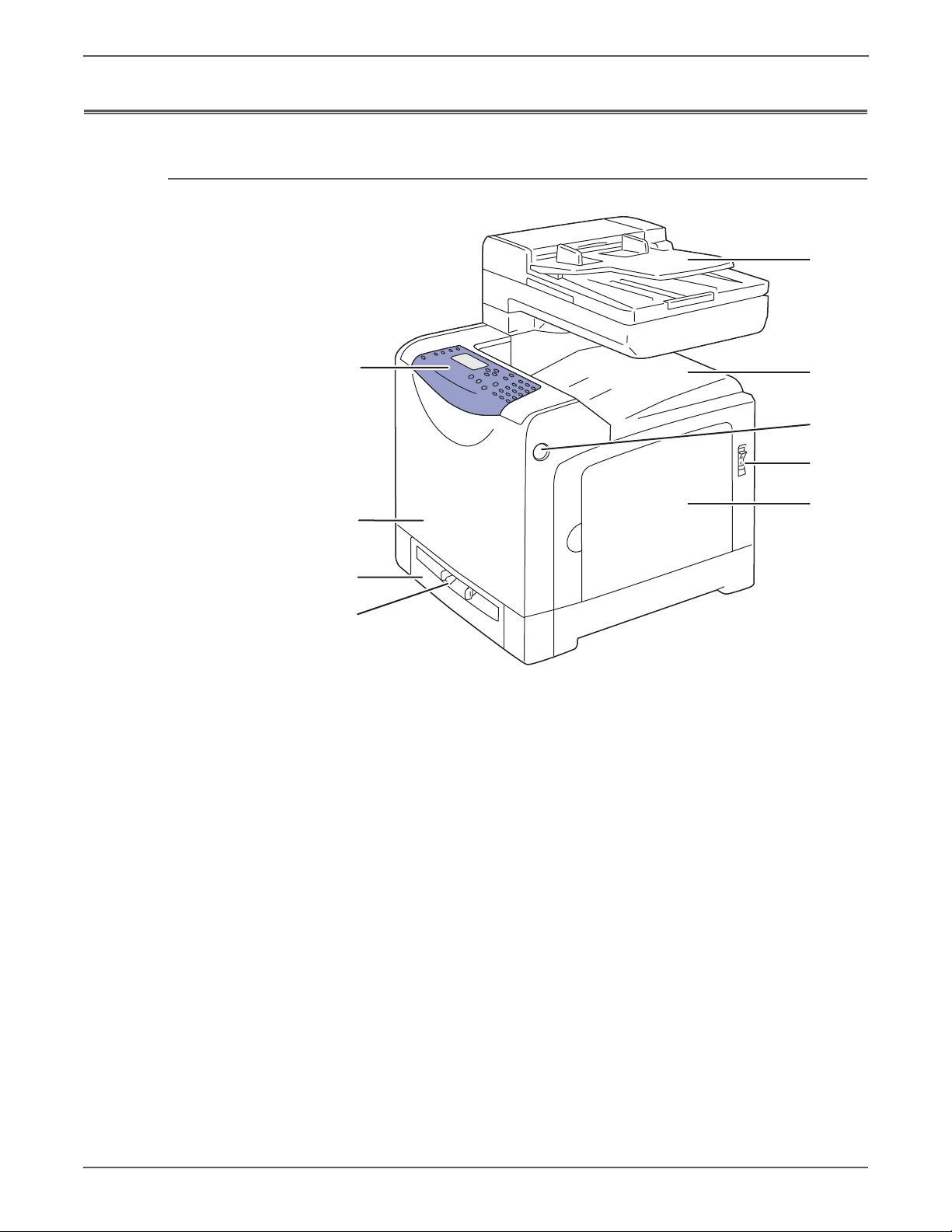
General Information
1
2
3
4
5
6
7
8
9
s6128mfp-126
Parts of the Printer
Front and Side Views
1. Automatic Document Feeder (ADF)
2. Output Tray
3. Front Door Release
4. Power Switch
5. Right Side Door
6. Sheet Feeder
7. Paper Tray
8. Front Door
9. Control Panel
1-4 Phaser 6128MFP Service Manual
Page 26
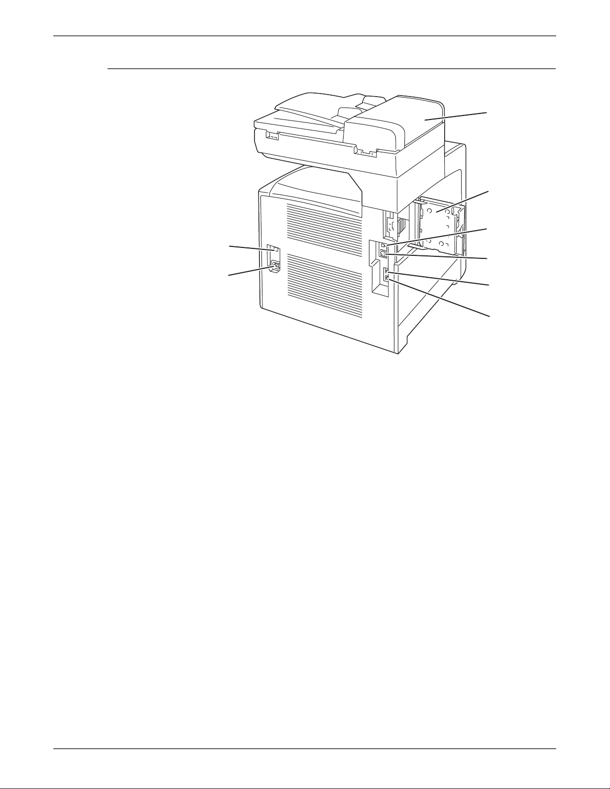
Rear View
1
2
3
4
5
6
7
8
s6128mfp-127
General Information
1. A D F Co v e r
2. E S S Co v e r
3. U S B Po r t
4. Ethernet Port
5. P h o n e Li ne o u t
6. P h o n e Li ne i n
7. P ow e r t es t
8. AC input
Phaser 6128MFP Service Manual 1-5
Page 27
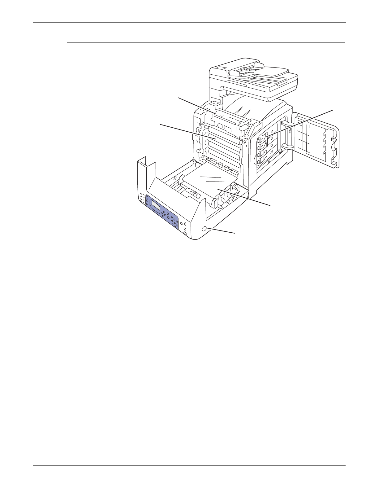
General Information
s6128mfp-128
2
1
3
4
5
Internal View
1. F u s e r
2. I m a gi n g U ni t
3. Toner Cartridges
4. T r a n sfe r B e l t
5. F ro n t C ov e r R e le as e
1-6 Phaser 6128MFP Service Manual
Page 28
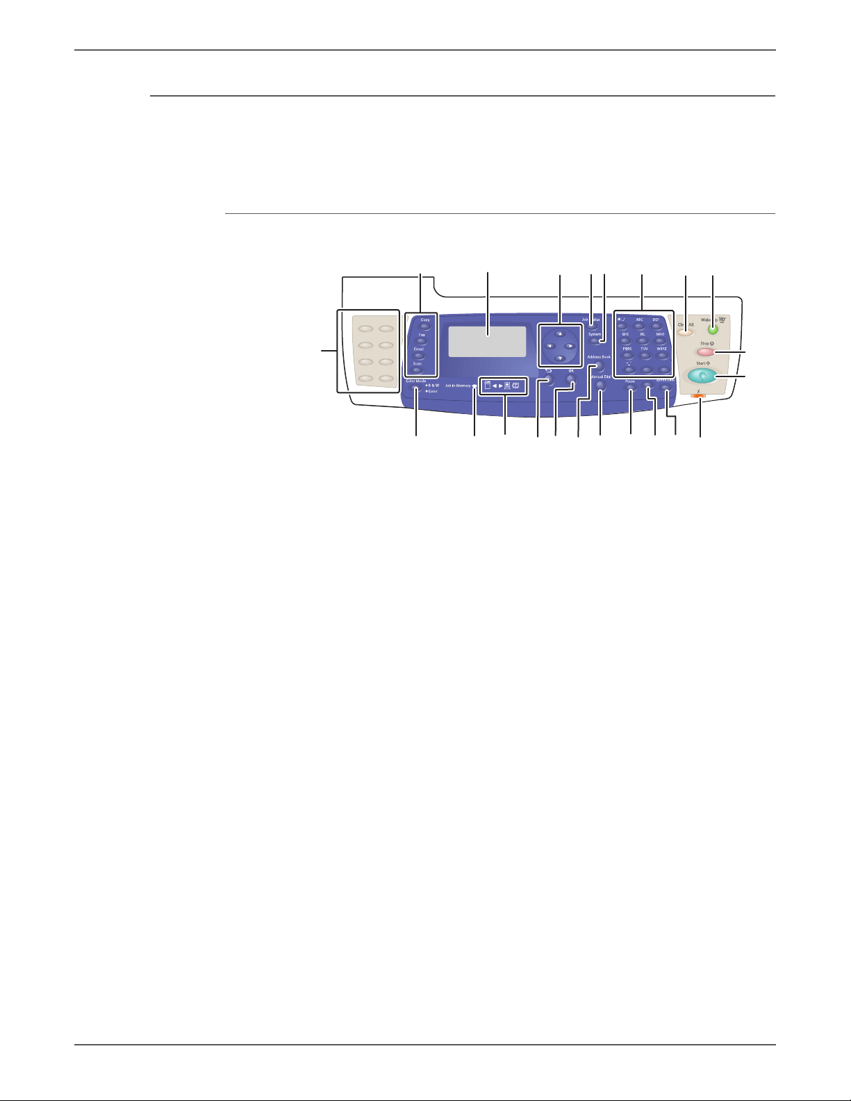
Control Panel
s6128mfp-129
1 4 7 82 356
9
10
11121314151617181921
20
22
Control Panel Button Descriptions
General Information
The Control Panel consists of multiple LEDs, a display, and several function
buttons. These buttons are used to navigate the menu system, perform functions,
and select modes of operation.
Phaser 6128MFP Service Manual 1-7
Page 29

General Information
1. Function Select
buttons
2. Display Indicates messages, menus, and toner levels.
3. Arrow buttons Scroll through the menus. The Back Arrow
4. Job Status button Press to check active job status.
5. System button Switches the display to the Setup menu. The
6. Alphanumeric key pad Use to enter letters and numbers for names and
7. Clear All button Clears all text or numbers or instructions.
8. Power Saver button This light is on in power saver mode. Push the
9. Stop button Cancels the current print job.
10. Start button Press to start a copy, scan, or fax job.
11. Error LED The red light indicates an error condition.
Press to use the Copy, Fax, Email, and Scan
menus on the display screen.
button also displays the Walk-Up Features
menu.
green light indicates that the printer is ready. If
the light is blinking, the printer is receiving data.
phone numbers.
button to exit power saver mode.
12. Speed Dial button Press to access directories of group or individual
fax telephone numbers.
13. Clear button Deletes a single character each time the button
is pressed. For use when entering email
addresses and telephone numbers.
14. Redial/Pause button Press the button to recall the last fax number
used or to insert pauses in fax numbers.
15. Manual Dial button When faxing, press this button to enter a fax
number with the alphanumeric key pad.
16. Address Book button Press to access the Fax and Email address books.
17. OK button Press to accept the setting selected.
18. Exit button Press to go up one level in the menu.
19. Arrow LEDs These LEDs indicate the flow of data either into
or out of the printer.
20. Job in Memory LED When illuminated, it indicates that there is a job
in the printer’s memory.
21. Color Mode button Press to switch between Color and Black and
White modes for your copy, fax, and scan job.
22. One touch keypad Use to dial stored speed-dial numbers.
1-8 Phaser 6128MFP Service Manual
Page 30

LED Indicators
Note
LED State Printer State
Green Ready to Print or in Power Saver mode
Flashing Green Processing print job
Red Error occurs, can be fixed by user
Flashing Red Error occurs, cannot be fixed by user
Control Panel Shortcuts
Mode Buttons Pressed at Power On
Service Diagnostics Up + Down arrow buttons
General Information
Maintenance Items
Reset Password to 0000
(used when the Control Panel menus
are locked)
Boot Download for Controller Up + Down + System buttons
Routine maintenance items are parts or assemblies that require periodic
replacement. These items are typically customer replaceable (CRU).
The listed items have limited life and require periodic replacement.
Maintenance Items
Item Print Life
Imaging Unit Approximately 30,000 pages
Fuser Up to 50,000 pages
Tray Separator Pad Up to 50,000 pages
Tray Pick Roller Up to 50,000 pages
ADF Feed Roll Assy Up to 35,000 pages
System
ADF Seperator Pad Up to 35,000 pages
Print life is based on “typical” office printing and 5% coverage per color on 24
lb. paper. Print life figures are not guaranteed and varies depending on usage
habits. Imaging Unit print life is based on 3-page jobs using letter-size paper.
Phaser 6128MFP Service Manual 1-9
Page 31

General Information
s6128mfp-130
PL10.10.3
ADF Feed Roller Assembly
PL10.10.4
ADF Separator Pad Assembly
PL6.1.1
Fuser Assembly
PL4.1.21
PHD Assembly
PL10.3.5
Separator Roller
Assembly
PL3.2.4
Feed Roller
Assembly
PL5.1.21
Toner Cartridge (K)
PL5.1.22
Toner Cartridge (C)
PL5.1.23
Toner Cartridge (M)
PL5.1.24
Toner Cartridge (Y)
Consumables
Consumables consist of 4 Toner Cartridges.
Each Toner Cartridge has a CRUM (Customer Replaceable Unit Meter) to record
toner usage information. A CRUM counts the amount of remaining toner. When
toner empty is detected, Life End status is displayed to indicate toner empty.
CMY Toner is not consumed when printing in monochrome mode or when printing
Gray scale. Internal counters track consumables and maintenance life.
Life ratings are based on A-size sheets at 5% coverage.
Toner Cartridge Print Life
C,M,Y Black
Standard Capacity 1,000 pages 1,000 pages
High Capacity 2,500 pages 3,100 pages
1-10 Phaser 6128MFP Service Manual
Page 32

Specifications
Printer Specifications
General Information
Characteristic Specification
Printing Technology Recording System: Tandem electro-photographic system
using OPC Drum and direct transfer by the Transport Belt
Exposure System: 4 semiconductors laser beam
scanning system
Transfer System: Four-color finished toner image is
transferred onto the paper
Fusing System: Thermal fusing system by Free Belt Nip
Fusing (FBNF)
Print Volume Average 450 PV/month
Maximum 40,000 PV/month
Median 300 PV/month
Color Medium Cyan, Magenta, Yellow, and Black Toner Cartridges
Resolution /
Addressability (dpi)
Print-Quality Mode 600 x 600 x 1bit (Standard)
Average Image
Coverage
Maximum Image
Coverage
Printer Life 100,000 pages
Maximum Duty
Cycle
Warm-Up Time Less than 30 seconds from Power On
Operating System Windows 2000/ 2003 Server/ XP Pro/ XP/
Standard 600 x 600 x 1
Enhanced 600 x 600 x 4
600 x 600 x 4bit (Enhanced)
Color 5% each CMYK
Mono 5%
240% for all C, M, Y, K combined
40,000 pages/month*
Vista
Macintosh OS 10.2 or higher
Linux Redhat, SuSe, and TurboLinux 10
Desktop
* Assumes a 30 day month of printing.
Phaser 6128MFP Service Manual 1-11
Page 33

General Information
Scanning Specifications
Scanning Specifications
Characteristic Specifications
Scanning Mode
■ Platen Mode: Scan document using the document glass
■ Constant Velocity Transport (CVT) Mode: Scan
document via the Automatic Document Feeder (ADF)
Maximum Scan Size
■ Platen Mode: 215.9 mm x 297 mm (8.5 in. x 11.7 in.)
■ CVT mode; 215.9 mm x 355.6 mm (8.5 in. x 14 in.)
Media Size
Minimum
Maximum
■ Fast Scan Direction: 148 mm (5.8 in.)
■ Slow Scan Direction; 210 mm (8.3 in.)
■ Fast Scan Direction: 215.9 mm (8.5 in.)
■ Slow Scan Direction: 355.6 mm (14.0 in.)
USB Scanning
Resolution Up to 9600 dpi
■ Scan Interface
■ File Formats
TWAIN/ WIA
BMP, JPG, PDF, TIFF
Network Scanning
Resolution Up to 600 dpi
Color Mode Color, Black & White
Original Type Text, Photo, Mixed
File Format JPG, PDF, TIFF
Lighter/Darker 7 levels
Sharpness 3 levels
Contrast 3 levels
Auto Exposure Off, Normal, Higher (1, 2)
Scan to Desktop via
Up to 6 SMB servers
SMB
Scan to FTP Up to 6 FTP servers
Scan to E-mail Yes (no individual user log in)
Network Scan to
Computer via SMB
Document Glass,
150 dpi, mixed,
9 sec.
letter size
1-12 Phaser 6128MFP Service Manual
Page 34

General Information
Scan Performance
Function Document Black & White Color
Copy Specifications
Copy Specifications
USB Scan to
Application (TWAIN)
USB Scan to
Computer (via Express
Document Glass, 300 dpi,
24-bit color, letter size
Document Glass, 300 dpi,
24-bit color, letter size
Scan Manager)
Network Scan to
Computer via SMB
Network Scan to Email
Document Glass, 150 dpi,
mixed, letter size
Document Glass, 150 dpi,
mixed, letter size
Characteristic Specifications
Resolution
■ Black & White: 600 x 600 dpi
■ Color: 600 x 600 dpi
Copy Mode Color, Black & White
8 sec. 10 sec.
12 sec. 33 sec.
9 sec. 8 sec.
9 sec. 10 sec.
Output Type Standard, Enhanced (Best)
Or i g i n a l Type Text, Phot o , Te x t / P ho t o
Reduce/Enlarge 25%-400%
Lighter/Darker 7 levels
Color Saturation 3 levels
Sharpness 3 levels
Color Balance 4 colors, 3 densities, 5 levels
Auto Exposure Off, Normal, Higher (1, 2)
Number of Copies 1-99
Multiple Up (N to 1) Off, Auto, ID Copy, Manual
Duplex Copy On, Off
Poster 2x2, 3x3, 4x4
Auto Fit On, Off
Cloning On, Off
Collate
■ Color: 19
■ B/W: 50
Phaser 6128MFP Service Manual 1-13
Page 35

General Information
Fax Specifications
Fax Specifications
Characteristic Specifications
Communication
Mode
Resolution
Lines:
Pixels
Supported Protocols
Compression
Form at
Incoming Call
Control
■ Priority 1: ITU-T Super G3
■ Priority 2: ITU-T G3 ECM
■ Priority 3: ITU-T G3
B&W (Fast Scan x Slow Scan)
■ 8 pixels x 3.85 line / mm
■ 8 pixels x 7.7 line / mm
■ 8 pixels x 15.4 line / mm
■ 16 pixels x 15.4 line /mm
■ 400 x 400 ppi / 25mm
■ 300 x 300 ppi / 25mm
■ 200 x 200 ppi / 25mm
■ 100 x 100 ppi / 25mm
■ V. 34 (Max.33.6 kbps)
■ V. 17 (14.4/12/9.6/7.2 kbps)
■ V. 29 (9.6/7.2 kbps)
■ V. 27ter (4.8/2.4 kbps)
MH, MR, MMR, JBIG (B&W 1-bit)
JPEG (Color Fax)
Telephone Mode, Fax Mode, Telephone/ Fax Mode,
Answering Machine Mode, Distinctive Ring Pattern
Detection (DRPD)
Lighter/Darker 7 levels
DM Protection Reject junk Fax
Forwarding & Local
Supported
Print
Color Fax Resolution is fixed by 200 x 200 dpi
Fax Address Book Up to 200 Speed Dial numbers and up to 6 Group Dial
numbers stored in device memory. The Group Dial
Numbers may have up to 200 fax numbers associated
with each group; however, the total number of allowable
fax numbers for all groups is 200.
Lan Fax
Resolution Normal: 200 x 100 dpi
Fine: 200 x 200 dpi
Super Fine: 400 x 400 dpi
Driver PCL driver - supported
PS driver - not support
Color Not support
Delayed Start Up to 24 hours
Broadcast Sending Up to 30 destinations
Zoom 25%-400% (same as printer driver)
1-14 Phaser 6128MFP Service Manual
Page 36

Fax Specifications (continued)
Characteristic Specifications
General Information
Auto Reduction/
Enlarge (Auto Fit)
Rotation On/Off (same as printer driver)
N-Up 1/ 2/ 4/ 8/ 16/ 32 (same as printer driver)
Watermark Supported (same as printer driver)
Phone Book Up to 500 Speed Dial numbers and up to 500 Group Dial.
Memory Specifications
Characteristic Specifications
Memory Minimum 128 MB Onboard
Supported RAM Supports one 256 MB DDR2 DIMM in one
On/Off (same as printer driver)
Local phone book stored on PC not linked device.
memory
Maximum 384 MB
expansion slot with 128 MB mounted onboard.
Electrical Specifications
Characteristic Specification
Power Supply Voltage/Frequency
Line Voltages 110-127 VAC ± 10%
Frequency Range 50/60 Hz ± 3 Hz
Current Capacity 110 V Engine: < 9 A
Power Consumption (with all options, 110 or 220 V)
Power Saver Mode 18.4W or less
Standby Mode (Fuser On) 60W or less
Color Continuous Printing 360W or less
B/W Continuous Printing 360W or less
Maximum Value 1100 W or less
220-240 VAC ± 10%
220 V Engine: < 5 A
Phaser 6128MFP Service Manual 1-15
Page 37

General Information
Print Speed
Resolution
600 Standard 12/12 16/16
600 Enhanced 12/12 16/16
Environmental Specifications
Characteristic
Te mp e ra tu re
Operating 5 to 32° C (41 to 90° F)
Standby -20 to 40° C (-4 to 104° F)
Humidity (% RH)
Operating 15 to 85% RH
Standby 5 to 85% RH
Altitude
Color
A/A4
Mono
A/A4
Specification
Operating 0 to 3,100 meters (10,171 feet)
Acoustic Noise LWA(B) Sound Power Level (B) Sound Pressure (dBA)
Printing 6.16 51.6
Standby 4.3 25.7
1-16 Phaser 6128MFP Service Manual
Page 38

Operating Mode
General Information
Mode Condition Description
Running Mode The printer is under operating condition
such as running or recording.
Fusing Maintained at operating temperature.
Exposure The Laser Unit Motor runs at the
operating speed.
Recording The system is operating.
Cooling Fan The fan operates at high speed.
Control Panel
Operation
Fax
LCD - Backlight: On
LED - Ready LED is turned On.
Sending or receiving a Fax.
Communication
Ready Mode The printer is in standby status, ready to
run.
Fusing The system keeps the standby
temperature.
Exposure The system is at Pause.
Recording The system is at Pause.
Cooling Fan The fan operates at low speed.
Control Panel
Operation
LCD - Backlight: On
LED: If printer is online, Ready LED is
turned On.
Power Saver
Mode (Deep
Sleep)
The printer enters into the Power Saver
mode to reduce power consumption
when it has not received print data for
the specified time.
Fusing The system is Off.
Exposure The system is at Pause.
Recording The system is at Pause.
Cooling Fan The system is Off.
Control Panel
Operation
NOTE
When the printer receives a print job or a button is pressed, the printer exits the Power
Saver mode and enters the Ready mode.
LCD: Off, LCD Backlight: Off
LED: Power Saver LED is turned On.
Phaser 6128MFP Service Manual 1-17
Page 39

General Information
First Print Output Time (FPOT)
First Print Output Time is defined as a time from when the engine receives a Start
signal in Ready state, until a single page is printed and delivered to the output tray.
The following conditions are applied:
• The Controller does not keep the print engine waiting
• The printer is at Ready mode
• Paper is A size Short Edge Feed (SEF)
• Process control time is not included
Mode Tray FPOT (sec.)
Color Tray As fast as 17.0 sec.
Manual Feed As fast as 17.0 sec.
Mono Tray As fast as 14.0 sec.
Manual Feed As fast as 14.0 sec.
First Copy Output Time
First Copy Output Time (FCOT) is defined as the time when the Start button is
pressed until the trail edge of the first copied media passes the printer Exit Roller.
The following conditions are applied:
• The Controller does not keep the print engine waiting.
• The printer is at Ready mode (Laser Unit Motor Off, Fuser Ready).
• Paper is A size Short-Edge Feed (SEF).
• Document is on the document glass (Document setting: Platen mode).
• Media: Media feed from the standard media tray.
Mode FCOT (sec.)
Color Less than 30.0 sec.
Mono Less than 21.0 sec.
1-18 Phaser 6128MFP Service Manual
Page 40

Image Specifications
Note
Refer to “Print-Quality Troubleshooting” on page 5-1 for detailed specifications.
Characteristic Specification
Maximum Print Area 210.9 mm (8.2 inches) x 351.6 mm (13.8 inches)
Guaranteed Print Area 207.9 mm (8.2 inches) x 347.6 mm (13.7 inches)
Skew 190 mm ± 1.2 mm
Perpendicularity 114.5 mm ± 0.8 mm
Parallelism
Horizontal 180 mm ± 1.2 mm
Vertical 234 mm ± 1.2 mm
Linearity
General Information
The printed image has 4 mm margins on all sides.
Horizontal 190 mm ± 0.5 mm
Vertical 234 mm ± 0.5 mm
Slant 269 mm ± 1.2 mm
Magnification Error
Horizontal Simplex 234 mm ± 0.5 mm
Horizontal Duplex 234 mm ± 0.8 mm
Vertical Simplex 190 mm ± 0.5 mm
Vertical Duplex 190 mm ± 0.8 mm
Registration
Leading Edge 10.0 mm ± 2.0 mm
Side Edge 8.5 mm ± 2.5 mm
Phaser 6128MFP Service Manual 1-19
Page 41

General Information
s6128mfp-131
250 mm/
9.84 inches
425 mm/16.73 inches
100 mm/3.94 inches
100 mm/
3.94 inches
585 mm/
23.03 inches
507 mm/
19.96 inches
600 mm/23.62 inches
320 mm/
12.60 inches
Physical Dimensions and Clearances
Dimensions
Height 585 mm (23”)
Width 420 mm (16.7 in.)
Depth 507 mm (20”)
Weight (base printer
without consumables)
Minimum Clearances
25 kg (55 lb.)
1-20 Phaser 6128MFP Service Manual
Page 42

Mounting Surface Specifications
s6128mfp-132
10°
10°
10°
10°
These specifications apply to any printer used as a table-top printer.
Mounting surface flatness must be within the specified range. The printer must
not be tipped or tilted more than 10 degrees or 7 mm.
General Information
Known problems that occur as a result of exceeding the mounting surface
specifications are:
• Color-to-Color mis-registration, primarily in the horizontal (laser scan)
direction.
• A smear or line of toner approximately 40 mm from the trailing edge of the
print.
Phaser 6128MFP Service Manual 21
Page 43

General Information
Media and Tray Specifications
The following tables list the recommended Xerox paper for the printer.
Supported Paper Size
Paper Type Dimension
Manual Feed Tray
Letter 8.5 x 11 in. Yes Yes
Legal 8.5 x 14 in. Yes Yes
US Folio 8.5 x 13 in. Yes Yes
Executive 7.25 x 10.5 in. Yes Yes
A4 210 x 297 mm Yes Yes
A5 148 x 210 mm Yes Yes
B5 JIS 182 x 257 mm Yes Yes
Custom Size
a. Minimum 3"x5", maximum 8.66"x14".
a
Ye s Ye s
Supported Paper Types and Weights
Paper Type Dimension
Plain Paper
65-90 g/m
Letter Head 85-120 g/m
2
2
(22-32 lb.
Manual Feed Tray
Ye s Ye s
Ye s Ye s
Bond)
Pre-Punched 65-90 g/m
2
(17-24 lb. Bond) Yes Yes
Color
Thin Card Stock 100-163 g/m
Special 100-163 g/m
2
2
Ye s Ye s
Ye s Ye s
(30-60 lb. Cover)
Thick Card Stock 170-216 g/m
Glossy Paper 100-163 g/m
Thick Glossy Paper 164-216 g/m
2
2
2
Ye s No
Ye s Ye s
Ye s Ye s
Label N/A Yes Yes
Supported Envelopes
Type Di mension
Manual Feed Tray
Envelope #10 4.12 x 9.5 in. Yes Yes
Monarch Envelope 3.87 x 7.5 in. Yes Yes
C5 Envelope 162 x 229 mm Yes Yes
DL Envelope 110 x 220 mm Yes Yes
NOTE
Do not use envelopes with hot melt glue, windows, or metal clasps.
22 Phaser 6128MFP Service Manual
Page 44

Controller Functions
Job Control
Cancel Print
Forced Output
IP Filter
General Information
Cancel a print job while printing is in progress using the Stop button on the Control
Panel. Job cancellation is not immediate. Depending on the job size, it may take
several seconds to completely cancel.
This function forces the printer to print the received data when the printer is
waiting for the remaining data during job processing.
Accept or reject print jobs from up to five specified IP addresses. IP filter is
available only to LPD and Port9100.
Job Recovery
When a print job fails due to a jam, the printer automatically restarts the job after
the jam is removed
Job Timeout
When job transmission is interrupted for a certain period of time, the print data is
deleted as an error. The timeout setting can be changed using the menu on the
printer’s Control Panel.
Print Volume Management
Print Volume (PV) Management manages print volume per user and can manage
up to 50 users.
RAM Disk
RAM Disk functions when memory is expanded, enabling Collation, Secure Print,
Proof Print, Form Overlay, and Font Download. 256 MB is needed to enable RAM
Disk and all related functions.
Collation
Phaser 6128MFP Service Manual 23
Page 45

General Information
The job is stored in the memory and multiple copies are printed. When the entire
job does not fit in the memory, the printer prints one copy up to the stored pages,
and the remaining are discarded.
An error message will appear on the Control Panel: “Error xxxx Press set key.”
Two options are available to ensure Job Collation will process effectively:
• Break large print job into multiple small print jobs
• Increase memory for the printer
Secure Print
When memory is expanded to 256 MB or more, the printer holds print data,
including a User Password (11 digits), User Name, and Document Name in the
memory.
• User ID – consists of a variable length from 1 to 24 byte characters (20HFFH). The driver requests the User ID from the user when the Secure Print
option is selected. A user ID cannot be blanked with only space characters.
• User Password – consists of a variable length from 0 to 11 digits. The
password is an optional input and hidden from the user interface by displaying
“*” for each digit. If a password is not specified, the driver will accept it as a
zero-length string so that a password will not be required when requesting job
output from the printer.
• Document Name – consists of a variable length from 0 to 24 characters (20HFFH) that specifies the document name.
The data will not be printed until the same password, user name, and document
name are provided via the printer menu on the Control Panel. User can remove or
keep the data after printing the document. The data remains in the printer
memory as long as it is not cleared and will be cleared when the printer is turned
off. User can omit entering a password (this is called Store Print - not available for
MAC OS 10.2.).
Proof Print
Proof Print can be selected only when multiple sets of prints are specified in the
printer driver. Proof Print requires at least 256 MB of memory. The printer prints
only the first set of the print data including a user name and document name
specified in the printer driver. User can keep or remove the data using the printer
menu on the Control Panel. The data remains in the printer memory as long as it is
not cleared and erased when the printer is turned Off. This function is not available
for MAC OS 10.2 and Linux operating systems.
Form Overlay
The function for writing PCL6 forms are downloaded into RAM Disk.
Font Download
PCL6 fonts can be downloaded into RAM Disk.
24 Phaser 6128MFP Service Manual
Page 46

Billing Meters
The Billing Print counter provides the number of pages printed properly (simplex
print is counted as 1 and duplex print is counted as 2 - including N up).
If an error has occurred after the one side printed properly during duplex printing,
it is counted as 1.
Color Print Counter Counts the number of pages printed in color (7
Mono Print Counter Counts the number of pages printed in mono (7
Total Print Counter Count the total number of pages printed in color and
ID Print
General Information
Counter Description
digits).
digits).
mono (7 digits).
User can position and print the User Name on the upper right, upper left, lower
right, and lower left (only for PCL6) of the page.
Non-Genuine Mode
When the Toner Cartridge life has ended, the printer stops accepting print request
(life of the Toner Cartridge is counted by the counter in the CRUM). This mode can
be changed so the printer will not stop at the end of the Toner Cartridge rated life;
however, the printer will display an end of life message on the Control Panel.
Toner Cartridge Control Panel Display
To ne r
Cartridge Control Panel Display Functionality
Life
Normal Status
Xerox Xerox (TM)
To n er
Cartridge
Xerox (refill
To n er
Cartridge)
Xerox (TM)
To n er
Cartridge
Warning
Error
Replace
Soon
Replace
Soon
End of
Life Error
Replace
To n er
Cartridge
Empty Prints with full
Prints with full
functionality.
functionality up to
40% of the Toner
Cartridge life.
Other OEM
(non-Xerox
printer
manufacturer)
Phaser 6128MFP Service Manual 25
Non-Xerox
To n er
Cartridge
Printer displays error
and will not print.
Page 47

General Information
Note
Toner Cartridge Control Panel Display (continued)
To ne r
Cartridge Control Panel Display Functionality
Life
Normal Status
Warning
Error
End of
Life Error
Non-Xerox
To n er
Cartridge
Manufacturer
Maintenance Function
Firmware Update
The Image Processor Board can be updated by customers and service technicians
using a Windows PC or Macintosh with dedicated utilities. Firmware updates are
available at www.xerox.com/office/support.
Detailed procedures are available in “Firmware Update” on page A-10.
Boot Code can be updated via USB port only.
Image Processor Board Available Available
MCU Board
Non-Xerox
To n er
Cartridge
Updated Firmware Windows
a
No Life
Track ing
Via USB/IEEE1284 Via Network (port 9100)
Available Available
Replace
To n er
Cartridge
Prints with full
functionality.
a. MCU Board cannot be updated when ROM starts to be used for MCU Board.
Diagnostics
Two types of diagnostic functions are available:
1. Auto Diagnostics: The printer is checked when it is turned on. It is checked
whether hardware (ROM, RAM, ASIC, etc....) operates properly.
2. Manual Diagnostics: Only qualified service personnel can perform manual
diagnostics using the Service Mode in the Control Panel.
26 Phaser 6128MFP Service Manual
Page 48

Information Pages
s6128mfp-133
Configuration Page
General Information
Print the Configuration Page from the Control Panel > System > Information
Pages > Configuration. The Configuration Page includes this information.
Configuration Page Information
General Description Detail Description
Title Prints Title of the document
Product Name (Logo) Prints organization’s logo
General Total Impressions, Total Color Impressions, Total
Black Impressions, Memory Capacity, Printer
Language, Number of Fonts Available, PostScript
Ver sion, PostScript Serial Number, Firmware
Version, Boot Version, Engine Version, PostScript
CRD Version, Default Paper, Default Language,
Current Temperature, Current Humidity
Print Volume Print Volume for each paper size
Network Setup Firmware Version, MAC Address, Ethernet, TCP/IP,
Protocol, Host Access List, Adobe Protocol
Phaser 6128MFP Service Manual 27
Page 49

General Information
Configuration Page Information
General Description Detail Description
USB Setup Adobe Protocol
System Setup PowerSaver Time, Audio Tones, Time-Out,
Language, Auto Log Print, Print ID, Print Text,
Banner Sheet, RAM Disk, Tray Switching, mm/inch,
Start Up Page
Maintenance Auto Reg Adj., Non-Xerox Toner
PCL Paper Tray, Paper Size, Orientation, 2-Sided, Font,
Symbol Set, Font Size, Font Pitch, Form Line,
Quantity, Image Enhance, Hex Dump, Draft
Mode, Line Termination, Default Color
Control Panel Panel Lock
Tray Settings Tray
PCL Fonts List
The PCL Font List contains No., Fonts, Escape Sequence, Font ID, Sample
PCL Macro List
Print the PCL Macro List on A paper size from default tray.
Job History Report
The printer retains up to 20 job logs. Job History can be manually or automatically
printed when the number of the retained job logs reaches 20. Job History reports
include:
• Job sent data and time
• Input Interface (USB, LPD,...etc.)
• Document Name (File Name)
•Output Color
• User Name/Host Name
• Number of Printed Pages (Color/Mono)
• Number of Printed Impressions (Color/Mono)
•Paper Size
• Result (successful, error,...etc.)
28 Phaser 6128MFP Service Manual
Page 50

Error History Report
Phaser® 6128MFP-N
Color Multifunction Printer
Error History Report
System Fail History
Paper Jam History
Date
10/30/2008
Time
11:13
Paper Jam Type
IOT Remain Registration Jam
Date & Time : 10/30/2008 11:14
Page:1(Last Page)
XEROX CORPORATION and Fui Xerox Co., Ltd. 2008
The printer retains up to 42 jam and up to 42 fatal errors.. The error logs include
the following information:
• Jam Errors: Item No., Total Print Count, Paper Jam Type
• Fatal Errors: Item No., Total Print Count, Chain-Link Code
General Information
Print Meter (Print Volume Report)
The Print Meter page contains, Date of Initialization, Job Accounting User Name,
Pages, Sheets, and Date/Time.
Phaser 6128MFP Service Manual 1-29
Page 51

Theory of Operation
In this chapter...
• Phaser 6128MFP Operational Overview
•Printing Process
•Media Path
• Major Assemblies and Functions
• Printer Modes
• Printer Control
• Drive Transmission
Chapter
2
Page 52

Theory of Operation
Phaser 6128MFP Operational Overview
The Phaser 6128MFP is a full-color multifunction printer that uses raster output
scanner (ROS) lasers with an electrophotographic four-color CMYK process. The
tandem system consists of four color drums (C, M, Y, and K) which creates the
toner image.
The following block diagram provides the sequence of events for the xerographic
process (dashed lines) and the paper flow (solid lines) into and out of the printer.
Print Process Block Diagram
Imaging Unit
(1) Charge
(2) Exposure
(3) Development
(5) Cleaning
Transfer Belt
(4) Transfer (Drum to Paper)
(7) Cleaning
Paper
(6) Fusing
s6128mfp-001
2-2 Phaser 6128MFP Service Manual
Page 53

Printing Process
Theory of Operation
The print process consists of the following steps:
1. Charging – The Drum surfaces are charged with electricity.
2. Exposure – The Drums are exposed to laser beams.
3. Development – Image is developed with toner.
4. Transfer (Drum ---> Paper) – Four color finished toner image on the Drums is
transferred onto the paper.
5. Imaging Unit – Excess toner is removed from the Drum and BCR.
6. Excess Toner Collection – Excess toner is moved to the collection box.
7. Fusing – The Fuser applies toner on to paper using heat and pressure.
Exit Pinch Roller (Fuser)
Exit Roller (Fuser)
Heat Roller (Fuser)
Fuser Belt (Fuser)
PHD
BCR (PHD)
BCR Cleaner Roller (PHD) Magnet Roller (PHD)
Drum (PHD)
Fuser
BTR (Printer)
BTR (Printer)
BTR (Printer)
BTR (Printer)
Drive Roller (Printer)
s6128mfp-002
Phaser 6128MFP Service Manual 2-3
Page 54

Theory of Operation
s6128mfp-003
Cleaning Roller
BCR
Photoreceptor
Conductor
Drum
HVPS
Charging
The drum surface is charged with negative electricity by discharging of the bias
charge roller (BCR) while rotating at a constant speed. This process is performed in
parallel for Cyan, Magenta, Yellow, and Black colors.
The BCR is kept in contact with the drum and rotates following the rotations of the
drum. The BCR is a conductive roller, which receives negative voltage from the
High-Voltage Power Supply (HVPS) and discharges a negative Direct Current (DC)
voltage.
The drum surface is uniformly and negatively charged with DC bias voltage. The
drum surface is a photoreceptor (which is an insulator in a dark area and a
conductor when receiving light) and the drum inside is composed of conductor.
The cleaning roller is a sponge that contacts the BCR to catch the toner.
2-4 Phaser 6128MFP Service Manual
Page 55

Exposure
: Laser beams (Y)
: Laser beams (M)
: Laser beams (C)
: Laser beams (K)
s6128mfp-004
Front
Drum (K)
Drum (C)
Drum (M)
Drum (Y)
Polygon Mirror
Mirror
Mirror
Lens
Mirror
Mirror
Mirror
Lens
Mirror
Lens
Mirror
Lens
Mirror
Mirror
Lens
Laser Diode
Board
Polygon Mirror
Scanner
SOS Board
Lens
Lens
Mirror
Mirror
Mirror
Mirror
Rear View
SOS Sensor
Theory of Operation
Four laser diodes (one for each color) in the Laser Unit emit laser beams. The
beams are directed by mirrors to the rotating polygon mirror attached to the
scanner motor. As the polygon mirror rotates, the beams are directed through a
series of lenses and mirrors to each of the drums, which are scanned by the beams
from end to end in the axial direction.
Phaser 6128MFP Service Manual 2-5
The negatively charged drum surface is scanned by the laser beams to form an
invisible electrostatic latent image on the drum surface. The process is performed
in parallel for Cyan, Magenta, Yellow, and Black colors.
The area on the surface where the laser beam strikes becomes conductive. The
negative charge on the surface flows to the more positive drum, lowering the
voltage potential. In this way the surface areas exposed to the laser beam become
the electrostatic latent image.
Page 56

Theory of Operation
Laser Unit
Laser Beams
Laser Beam
Laser Beam
Laser Beam
Negative Electric Charge
Positive Electric Charge
Photoreceptor
Photoreceptor
Conductor
Conductor
Drum
Electrostatic
Latent Image
Electrostatic
Latent Image
Potential on
Drum Surface
-V
0
Drum Surface
Concept of Drum
s6128mfp-005
2-6 Phaser 6128MFP Service Manual
Page 57

Development
HVPS
s6128-006
: Negative Electric Charge
: Positive Electric Charge
: Toner
: Carrier
Trimmer Rod
Paddle
Toner Cartridge
Auger
Auger
Magnet Roller
Agitator
Drum
Theory of Operation
Toner is electrically attached to the invisible electrostatic latent image on the drum
surface to form the visible toner image on the drum.
The toner in the Toner Cartridge is agitated by the built-in agitator and fed into
the developer. The augers are driven by the Toner Motor and the developer motor
in the Main Drive. The toner to be consumed according to the print count is
calculated and fed into the developer. This process, called toner dispensation, is
controlled by two processes: pixel count dispense control (PCDC) and automatic
density control (ADC).
The toner fed into the developer and the carrier in the developer are agitated by
the auger, and supplied to the magnet roller arranged in the drum surface area.
The toner and carrier are charged by friction due to agitation (toner in negative,
carrier in positive), and they are attracted electrically. A uniform layer is formed by
the trimmer bar as the carrier magnetic substance is attracted to the magnetic
roller.
Phaser 6128MFP Service Manual 2-7
The magnet roller is covered by a thin semi-conductive sleeve. The developer bias
voltage is supplied to the sleeve by the HVPS. Developer bias is negative DC
voltage combined with AC voltage. The magnet roller is kept at constant negative
voltage against the photoreceptor layer of the drum by DC voltage. Therefore, at
the area on the drum surface where the negative electric charge does not
decrease, potential is lower than the magnet roller, while the potential is higher
than the magnet roller at the area where the negative charge on the drum surface
decreases. The AC voltage shakes the developer on the magnet roller surface,
causing the toner to transfer to the drum.
Thus, the negatively charged toner is attracted only to the area on the drum
surface (electrostatic latent image) where the negative charge is lower than the
charge on the magnet roller, forming the toner image on the drum. Once the toner
adheres to the drum, the negative charge of the toner-bearing location increases,
which decreases the potential and the toner-attracting force.
Page 58

Theory of Operation
Drum Surface
Toner
Image
Electric Potential
on Drum
Developing
Bias
-V
0
s6128-007
s6128-008
Drum Surface
(Black Toner Image)
Drum Surface
(Cyan Toner Image)
Drum Surface
(Magenta Toner Image)
Drum Surface
(Yellow Toner Image)
Paper
Black
Toner Image
Cyan
Toner Image
Magenta
Toner Image
Yellow
Toner Image
Transfer (Drum ---> Paper)
The toner image formed on the drum surface is transferred onto the surface of the
paper. The toner is transferred onto the paper in the order of Y, M, C, and K.
2-8 Phaser 6128MFP Service Manual
Page 59

Imaging Unit
s6128-009
: Positive Electric Charge
: Negative Electric Charge
: Toner
Erase Lamp (LED Assembly)
Blade
Cleaning Roll
BCR
Drum
Conductor
Photoreceptor
Theory of Operation
• Bias Transfer Roller (BTR) – The BTR is a conductive roller that receives
positive voltage from the HVPS. The BTR contacts the rear side of the Belt and
applies the positive voltage to the Belt.
• Transfer B elt – The Transfer Belt is a conductive unit that receives positive
voltage from the BTR. After the negative charged toner image on the Drum
surface is drawn by the positive charge on the belt, it is transferred from the
Drum to the paper. The Transfer Belt feeds the paper toward the direction of
the Fuser.
Excess toner is removed from the Drum and the BCR surfaces, while excess charge
is also eliminated from the drum surface.
• Drum Cleaning – The cleaning blade contacts the surface of the drum
collecting the excess toner by scraping off toner.
• Cleaning Roller – The Cleaning Roller contacts the surface of the BCR
collecting the excess toner by scraping off toner.
• Charge Cleaning – When the Drum is charged by the BCR, any excess charge
hinders the Drum surface from being uniformly charged, which may lead to
print quality problems. The the latent charge pattern remaining on the
photoconductive drum is neutralized by the Erase Lamp (LED) to prepare the
drum for the next Exposure cycle.
Phaser 6128MFP Service Manual 2-9
Page 60

Theory of Operation
s6128mfp-010
Toner Cartridge
Collection Box
Auger Cleaning Side
Auger
Cleaner Blade
Excess Toner Collection
The excess toner is collected by the cleaner blade contacting the drum and is
moved to the Toner Cartridge collection box by two augers.
2-10 Phaser 6128MFP Service Manual
Page 61

Fusing
Theory of Operation
The image is bonded to the media by the Fuser. The heat roller with the heat lamp
melts the toner particles. Toner is fused onto the media by the combination of
heat and pressure.
Warm-Up Stand By Printing
Main Heater Lamp On On/Off On
Paper
Fixed Toner
Heat Roller
Heater Lamp
Nip Spring
Unfixed Toner
Nip Head
Felt
Belt
Belt Frame
Sheet
s6128-011
Phaser 6128MFP Service Manual 2-11
Page 62

Theory of Operation
Media Path
Media Path
Media is supplied from the Tray or the manual feed slot, and is transported into the
printer along the paper path as shown in the diagram.
Manual Feed Slot
Registration Assembly
Exit Roller in the Fuser
Transfer Belt
Fuser
Top Cover
Tray
Motor Drive/
Solenoid/Feed Roller
Motor Drive/Clutch/
Registration Roller
Motor Drive/Belt
Motor Drive/Heat Roller/
Pressure Belt
Multiple Sheet
Feed Prevention
Leading Edge
Registration
(Except SSI)
s6128-012
2-12 Phaser 6128MFP Service Manual
Page 63

Media Path Components
s6128mfp-013
: Laser Beam
: Paper Transfer
: Paper Sensors
Exit Roller
Heat Roller
Pressure Belt
Belt
Rubber Registration Roller
Metal Registration Roller
Exit Sensor
Manual Feed
No Paper Sensor
Registration Sensor
Separator Roller
Feed Roller
Tray No Paper Sensor
Media path components for the printer are shown in the following figure.
Theory of Operation
Phaser 6128MFP Service Manual 2-13
Page 64

Theory of Operation
s6128-014
Bottom Plate
Side Guide (L)
Side Guide (R)
End Guide
Separator Roller
Major Assemblies and Functions
Major functional components are classified into the following categories:
•Tray
•Feeder
• Manual Feed & Registration
• Transfer Belt and Fuser
•Laser Unit
• Toner Cartridge & Dispenser
•Imaging Unit
•Drive
•Electrical
Tray
• Separator Roller
The Separator Roller and Feed Roller pinch the media to prevent multiple
sheets from feeding.
• Left/Right Side Guide
The side guides move at a right angle to the paper transfer direction to align
the paper width.
•Tray End Guide
The end guide moves in toward the paper transfer direction to determine the
paper size.
2-14 Phaser 6128MFP Service Manual
Page 65

• Bottom Plate
s6128-015
Feed Roller
Separator Roller
Separator Roller
Friction Clutch
The bottom plate is locked to the Tray bottom when the Tray is pulled out of
the paper feeder, and unlocked when the Tray is installed in the paper feeder.
When unlocked, the bottom plate lifts the paper, pushing it against the feed
roller using spring tension.
Seperator Roller
The sheets loaded into the Tray are occasionally stuck together along the edges,
which can cause a multiple feed or a jam. The sheets are fed by the Feed Roller to a
position between the Feed Roller and the Separator Roller. Normally, when only
one sheet is fed, both the Feed Roller and Separator Roller rotate to allow the sheet
to pass.
However, when two sheets are fed concurrently, only the Feed Roller rotates. The
Separator Roller is locked, allowing the upper sheet to pass, separated from the
lower sheet that is stopped by the friction with the Separator Roller at rest.
The Separator Roller is pushed toward the Feed Roller by spring pressure, and
controlled by the Friction Clutch.
Theory of Operation
Phaser 6128MFP Service Manual 2-15
Page 66

Theory of Operation
s6128mfp-016
Feed Roller
Feed Solenoid
Tray No Paper Sensor
Feeder
• Tray No Paper Sensor
Detects the presence/absence of paper in the Tray based on the position of
No Paper Actuator.
2-16 Phaser 6128MFP Service Manual
Page 67

Theory of Operation
Tray No Paper Sensor
Tray No Paper Sensor
Paper
Bottom Plate
No Paper Actuator
No Paper Actuator
(No Paper Position)
• Feed Solenoid
The Feed Solenoid transmits drive energy from the Main Drive Assembly to the
Feed Roller.
• Feed Roller
When the Feed Solenoid operates, it allows the Feed Roller to rotate and feed
the paper.
s6128-017
Main Drive
Feed Solenoid
Feed Roller Drive
Feed Roller
s6128-018
Phaser 6128MFP Service Manual 2-17
Page 68

Theory of Operation
Manual Feed & Registration
Manual Sheet Feed
No Paper Sensor
Registration
Rollers
Manual Sheet Feed Actuator
(No Paper Position)
Manual Sheet Feed
No Paper Sensor
Manual Sheet
Feed Actuator
Paper
Registration
Rollers
s6128-019
• Manual Feed No Paper Sensor
Detects media in the manual feed slot by the change in actuator position.
Upon detecting the sheet, the Registration Roller rotates for a predetermined
duration to feed the sheet. The rollers stop immediately when the Registration
Sensor detects the media.
• Registration Sensor
The Registration Sensor detects paper when the paper leading edge reaches
the registration chute. When paper is fed from the manual feed slot, the
Registration Sensor measures the paper length. The On time of the
Registration Sensor determines the media length.
2-18 Phaser 6128MFP Service Manual
Page 69

Theory of Operation
s6128-020
Registration Sensor
Rubber Registration Roller
Metal Registration Roller
Registration Clutch
Registration
Output Spring
Registration Actuator Spring
Registration
Output Actuator
Registration Input Actuator
Registration Roller Actuator
Registration Sensor
Rear View
Front
• Registration Clutch
The Registration Clutch transmits drive energy from the Main Drive to the
rubber registration roller, and transports paper from the Tray and manual feed
slot toward the Imaging Unit. The timing of sheets feeding from the
Registration Assembly is adjusted by the duration of the Registration Clutch
operation so that the toner image on the drum is transferred to the correct
position on the sheet.
Phaser 6128MFP Service Manual 2-19
Page 70

Theory of Operation
Registration Rollers
Lead Edge Registration
When a sheet is fed from the Tray to the toner transfer position, the registration of
the sheet may not be correctly maintained due to misalignment of lead edges in
the tray.
To avoid this problem, the lead edge position needs to be aligned at the
Registration rollers before the sheet is fed in front of the Transfer Belt, or in front of
the BTRs.
Before the registration rollers are energized, the paper is advanced from the tray to
the rollers. This process aligns the leading edge as shown below.
By pushing the edge of the sheet against the registration roller that is not turning,
the lead edge of the sheet is registered.
Registration Rollers
Skewed Paper
Paper Size Control
The printer doesn’t have switches for detecting paper size, and the length of paper
is detected only by the Registration Sensor when feeding paper. If printing data
and paper size don’t match, an error is sent to the Image Processor board.
s6128-022
2-20 Phaser 6128MFP Service Manual
Page 71

Paper Detection
Front
s6128-023
Registration Output Spring
Registration Actuator Spring
Registration Output Actuator
Registration Input Actuator
Registration Input Actuator
Registration
Input Actuator
Registration
Input Actuator
Registration Input Actuator
Registration
Roller Actuator
Registration
Roller Actuator
Normal Position
Paper Detection: Trailing Edge
From Paper Tray
From Manual Sheet Feed
Paper
Paper
Paper
Registration Sensor
Registration Sensor
Registration
Sensor
Registration
Sensor
Registration
Sensor
Rear View
Registration
Sensor
Registration
Roller
Actuator
Registration
Roller
Actuator
Since the paper path from manual feed slot to the Registration Sensor is different
than from the Tray to the Registration Sensor, the Registration Sensor is provided
with the Registration In Actuator and the Registration Roller Actuator.
• The Registration Roller Actuator detects the sheet from the manual feed slot
and detects the tail edge of the paper from the Tray.
• The Registration In Actuator detects the lead edge of the paper from the Tray.
The movement of the Registration In Actuator does not affect the Registration
Roller Actuator.
Theory of Operation
Phaser 6128MFP Service Manual 2-21
Page 72

Theory of Operation
Transfer Belt and Fuser
Rear View
Exit Sensor
Front
Heater Lamp
Pressure Belt
NCS Temperature Sensor
STS Temperature Sensor
Heat Roller
Thermostat
Exit Roller
Fuser
ADC Sensor
Blade Assembly
Transfer Belt
The Transfer Belt consists of the transfer belt and ADC Sensor.
• transfer belt
• ADC Sensor
Transfer Belt
Belt
The Belt feeds the paper toward the direction of the Fuser.
The ADC Sensor detects the toner patches on the Belt and converts them to
voltage value. The voltage value is used to control the density of toner.
s6128-024
2-22 Phaser 6128MFP Service Manual
Page 73

Fuser
Laser Unit
Theory of Operation
The Fuser fixes transferred toner onto the paper using heat and pressure and feeds
the paper before and after toner is fixed. The Fuser consists of the following
components: Heat Roller, Heater Lamp, Thermostat, Temperature Sensor, Pressure
Belt, Exit Roller, and Exit Sensor.
•Exit Sensor
The Exit Sensor detects passage of printed pages after fusing on the
Actuator’s position changes.
Rear View
Mirror
Scanner
Lens
Mirror
Polygon Mirror
Front
Laser Diode
Board
Lens
Mirror
SOS Board
SOS Sensor
Mirror
Laser Unit
Windows
s6128-025
Phaser 6128MFP Service Manual 2-23
Page 74

Theory of Operation
The Laser Unit is an exposure unit that generates laser beams to form an
electrostatic latent image on the drum surface. The Laser Unit consists of the
following components: laser diode (LD) board, scanner, start of scan (SOS) board,
lenses, mirrors, and windows.
• Laser Diode Board
The laser diode board consists of four laser diodes (LDs) corresponding to C,
M, Y, and K. Each LD converts the electric signals of incoming image data into
laser waves. In order to stabilize the laser light quantity during formation of
an electrostatic latent image, the laser diode board monitors the intensity of
the laser beam to adjust it to the appropriate level. This process is called auto
power control (APC).
• Scanner
The scanner consists of a scanner motor that rotates at a constant speed and
a polygon mirror that is mounted on the motor shaft. The laser light output
from the LD is directed onto the polygon mirror. The polygon mirror, provided
with six reflecting mirror faces, changes the reflection angle of the laser light
as it rotates, thereby allowing the laser light to scan the drum along its axial
direction. Scanning is performed using one reflecting mirror face for each line.
• Start of Scan (SOS) Board
The SOS Sensor on the SOS Board converts incoming laser beam, upon
detection, to an electric signal as reference for starting scanning, and
transmits this signal to the MCU Board. The SOS sensor signals are used to
synchronize the starting point of the laser beam scanning with the starting
point of the image writing.
•Lenses
The laser light reflected from the polygon mirror reaches the drum surface via
the lenses, mirror, and window. The Lenses correct aberration.
•Mirror
The mirror directs the laser beam to the Imaging Unit.
• Window
The window is the area where the laser beams exit the Laser Unit.
2-24 Phaser 6128MFP Service Manual
Page 75

Toner Cartridge & Dispenser
Theory of Operation
Dispenser Motor (K)
Toner Cartridge (K)
Dispenser Motor (C)
CRUM Connector (K)
Toner Cartridge (C)
Dispenser Motor (M)
CRUM Connector (C)
Toner Cartridge (M)
Dispenser Motor (Y)
CRUM Connector (M)
Toner Cartridge (Y)
CRUM Connector (Y)
s6128-026
The Toner Cartridge is a customer replaceable item that includes the following
components:
• Customer Replaceable Unit Memory (CRUM) Connector
The CRUM Connector reads and writes the CRUM data. Printer specific
information is stored in the CRUM.
• Dispenser Motor (C/M/Y/K)
The Dispenser Motor provides the drive for the Agitator and Auger in the
Toner Cartridge, and supplies toner to the Developer.
Phaser 6128MFP Service Manual 2-25
Page 76

Theory of Operation
Print Cartridge
Drum (K)
LED Assembly
Drum (C)
Drum (M)
Drum (Y)
s6128-027
Developer (K)
Developer (C)
Developer (M)
CRUM
Developer (Y)
Rear View
Front
Imaging Unit
The Imaging Unit is a customer replaceable item that carries out the charging,
development, transfer, and cleaning steps in the print process (see “Printing
Process” on page 2-3).
The Imaging Unit consists of the following items:
• Developers
Each of the four Developers includes the Augers that distribute the toner and
the Magnet Roller that applies toner to the Drum to develop the latent image.
•Drums
Each drum is given a latent image to which toner is applied by the Developer.
The resulting toner image is transferred to the paper.
•CRUM
Information specific to the Developer/Imaging unit is stored in the CRUM.
•Erase Lamp (LED)
2-26 Phaser 6128MFP Service Manual
Page 77

Drive
Imaging Unit Erase LampErase Lens
LED AssemblyDrum
s6128-028
s6128-029
Sub Drive
Main Drive
Feed Drive
Theory of Operation
The light of the LED passes through the lens of the Developer, illuminates the
drum, and eliminates the charge on the drum.
The drive consists of three assemblies:
• Main Drive Assembly
Drives the Imaging Unit, Transfer Belt, Registration Rollers, and Feeder.
• Sub Drive Assembly
Supplies drive to the Fuser and Developers (C, M, Y, K).
Phaser 6128MFP Service Manual 2-27
Page 78

Theory of Operation
s6128-030
Black And White Mode
Black And White Mode
Full Color Mode
Full Color Mode
Drive From
Sub Motor
Gear D3 In
Color Mode
Switching Sensor
Color Mode
Switching Solenoid
Gear D3 Out
Cam C
Cam C
Gear C
Color Mode
Switching Sensor
Color Mode
Switching Solenoid
Cam C
Gear C
Drive From
Sub Motor
Drive To
Developer
(Y, M, C)
Gear D3 In
Gear D3 Out
Cam C
• Feed Drive Assembly
The Feed Drive Assy transmits the driving force from the Sub Drive Assembly
to relevant parts.
The drive path is changed by the Color Mode Switching Solenoid in the Feed
Drive Assy to allow drive from the Main Drive Assy to reach only the Black
Developer. This is done to ensure that the Sub Drive Assembly cannot rotate
the Yellow, Magenta, and Cyan Developers during B/W printing.
The Color Mode Switching Sensor detects whether the drive path is set for B/W
or full color.
2-28 Phaser 6128MFP Service Manual
Page 79

Electrical
s6128mfp-031
Power Switch
LVPS
IP Board
GFI Breaker
EEPROM
Humidity Sensor
Multi
Protocol
Network
Card (MPC)
HVPS
MCU Board
Fan
Theory of Operation
Side Cover Switch
Control Panel
Interlock Switch
Fan
The Fan removes heat from the printer to prevent overheating.
Power Switch
The Power Switch turns the printer AC Power Supply On/Off.
Phaser 6128MFP Service Manual 2-29
Page 80

Theory of Operation
Note
Low-Voltage Power Supply (LVPS)
Two types of LVPS are available: 100/120V and 230V. The LVPS supplies AC power
from the power source to the Fuser Heater; the LVPS also generates and supplies
stable low-voltage DC power used for the logic circuits. The LVPS contains a control
circuit for the Fuser heater, in addition to the power circuit.
LVPS Over-Current Protection Circuit
This circuit stops all outputs if the power supply voltage 3.3 VDC, 5 VDC, or 24 VDC
is shorted. After short is repaired, cycle main power to reset the circuit.
LVPS Over-Voltage Protection Circuit
This circuit stops all outputs, if the power supply voltage 3.3 VDC, 5 VDC, or 24
VDC exceeds the specified voltage of 32 VDC or less for 24 VDC, 7 VDC or less for 5
VDC, or 4.4 VDC or less for 3.3 VDC. The circuit resets when main power is cycled
after certain period of time.
Deep Sleep Mode (Power Saver)
The output of the following power supply are stopped according to the signals.
Signal +3.3 VDC +5 VDC +24 VDC
Sleep Off Off On
Deep Sleep Off Off Off
Machine Control Unit Board
The Machine Control Unit (MCU) Board controls the printing process based on the
communication with the printer Image Processor Board and information from the
Sensors or Switches. Major functions include:
1. Communicates with the Image Processor Board.
2. Receives information from the Sensors or Switches.
3. Controls the Main and Sub-Drive Assemblies.
4. Distributes low-voltage DC power from the LVPS to each component.
5. Controls the Laser Unit.
When replacing an MCU Board, be sure to transfer the contents of NVM from
the old MCU Board to the new MCU Board.
High-Voltage Power Supply (HVPS)
The HVPS provides high-voltage power to the components in the transfer belt and
Imaging Unit to perform charging, development, and primary transfer of the print
process to the BCR, BTR, and Developer.
2-30 Phaser 6128MFP Service Manual
Page 81

Theory of Operation
s6128mfp-033
RAM DIMM
USB
Connection
Ethernet
Connection
ADF Data Cable
Fax Board Connection
Electrically Erasable Programmable Read-Only Memory (EEPROM) Board
The EEPROM Board stores the printer unique information.
Image Processor Board
The Image Processor (I/P) Board (CONT AIO) is connected to the MCU Board,
which controls the printer, including diagnostic, interface, and image processing.
The primary function of the I/P Board is to receive host data through one of the
available ports (USB, or Ethernet, the Scannner, or FAX). The received host data is
buffered, stored, and sent to the print engine in a rasterized format.
When installing a new I/P Board in the printer, you must transfer the following
parts from the old board to the new board:
•Memory DIMM
•FAX Board
Humidity /Temperature Sensor
The Humidity/Temperature Sensor reads the humidity and temperature within the
printer.
Phaser 6128MFP Service Manual 2-31
Page 82

Theory of Operation
Host (Electric Signal)
Electronic Sub-system Control Board (Electric Signal)
Machine Control Unit (Electric Signal)
Laser Unit (Laser Beams)
Electrostatic Latent On Drum (Invisible Image)
Toner Image On Drum
Toner Image On Paper
Print Image On Paper
s6128-034
Computer
I/P Board
MCU Board
Laser Unit
Imaging Unit
Imaging Unit
Transfer Belt
Fuser
Interlock Switch
The Interlock Switch is a switch that interrupts the supply of +24 VDC power to the
HVPS or Motor upon the opening of the Front Cover.
Toner Access Door Switch
A switch that detects when the Toner Access Door is open.
GFI Breaker
Opens to shut off the AC power if it detects any voltage or current or leakage
current that exceeds the rating of the AC power supply.
Data Flow
The electrical signal flow for the print data from the printer I/P Board is shown in
the following diagram.
2-32 Phaser 6128MFP Service Manual
Page 83

Printer Modes
Operational Modes
Theory of Operation
The Phaser 6128 printer includes the following modes:
•Ready Mode
The printer is ready for printing.
• Printing Mode
Printing is in progress.
•Sleep Mode
The printer has entered a power saving state.
• Deep Sleep Mode
The printer has entered a power saving state.
Printer Control
Paper Size Detection
Laser Unit Light Quantity Control
The printer has no switches for detecting paper size; only the length of the paper is
detected by the Regi Sensor as the paper is feeding. If the detected size does not
match the size sent in the print data, an error is reported to the Image Processor.
Image data is sent to the Laser Unit as an electric signal (data are expressed with
high and low voltage values), and the laser diodes convert the image data from
electric signals to optical signals (data are expressed with blinking laser beams).
Variations in light quantity of laser beams or variations in the optical system (such
as lenses) or drum sensitivity cannot attain a proper electrostatic image.
Therefore, the laser beam light quantity is monitored and controlled by the laser
diodes.
The Laser Unit has four laser diodes for Yellow, Magenta, Cyan, and Black
respectively and the beam intensity is automatically adjusted for each color.
Phaser 6128MFP Service Manual 2-33
Page 84

Theory of Operation
Process Control
For stable printing, the parameters related to the image development must be
corrected as necessary. The process control is performed in two methods after
every 25 cumulative prints, upon termination of a print run, or during a continuous
run.
•Potential Control
• Toner Density Control
The following controls supplement the above controls:
• High Area Coverage Mode
• Admix Mode
Potential Control
To attain stable printing image density, the drum charging voltage, the developing
DC voltage, and the Laser Unit beam intensity are adjusted according to the
developing capability of each color carrier that varies momentarily. The adjusted
drum charging voltage, the developing DC voltage, and the Laser Unit beam
intensity are fed back to keep the printing image density constant.
The outline of controls is as follows:
1. The Humidity/Temperature Sensor detects humidity and temperature.
2. The patches of respective colors (Yellow, Magenta, Cyan, and Black) for the
potential control are generated and transferred on the transfer belt.
3. The ADC Sensor (Density Sensor) detects the density of the patch on the Belt.
4. The drum charging voltage, developing DC voltage, and the Laser Unit beam
intensity are adjusted for each color according to the detected patch density.
Toner Density Control
Toner density must be kept constant to attain stable printing. The control system
for this purpose is called toner density control.
1. PCDC (Pixel Count Dispense Control)
The amount of toner to be consumed in the developing process is calculated
by counting the video signals entered to the Laser Unit. The amount of the
toner to be consumed is calculated by the toner dispensing time. The toner
motor is driven for the calculated toner dispensing time when supplying the
toner to the Developer.
2. ADC (Auto Density Control)
The patches of respective colors (Yellow, Magenta, Cyan, and Black) for the
toner density control are generated under a specified potential condition, and
transferred on the Belt. The ADC Sensor measures this density, and the
measured value is compared with reference value. If the toner density is low,
the toner dispense quantity is increased at the next printing, or if the toner
density is higher, the toner dispense quantity is reduced at the next printing.
The toner dispense quantity is calculated by the toner dispense time. This
calculation is made for each color.
2-34 Phaser 6128MFP Service Manual
Page 85

High Area Coverage Mode
A continuous printing of any image of area coverage exceeding the toner dispense
capability causes the toner density in the Developer to be lowered.
The High Area Coverage Mode postpones the next page feed and dispenses extra
toner during this time, if the toner dispense time reaches the specified value
during a continuous printing.
Admix Mode
The Admix Mode dispenses toner immediately to prevent the reduction of toner
density, whenever the value of the toner density control patch measured by the
ADC Sensor falls far below the standard value, by dispensing extra toner. If the
toner density level cannot be recovered after this operation, it is determined that
toner has run out.
ADC Sensor Control Function
The ADC Sensor is a reflection type sensor that radiates light from its LED onto the
target and detects the reflected light at its photoreceptor and outputs electric
signals responsive to the amount of the detected light.
To ensure an accurate patch density measurement, the surface of the ADC sensor
is cleaned to remove soil due to toner, etc., and the light amount adjustment is
made so that the reflected light amount satisfies the prescribed value, when
creating the patch for potential control and toner density control.
Theory of Operation
Color Registration Control
The printer uses a tandem electro-photographic system with Organic Photo
Conductor (OPC) Drums and direct transfer by the transfer belt. Because the
images are formed on the individual Drums of the respective colors and then
overlapped to form one image, a color shift may occur. The color registration
control calculates how much the registration is shifted, and adjusts the Laser Unit
write timing.
The scan control adjusts all four colors in the process direction.
The color registration control is made from a change in inside temperature and the
print count at the execution of the process control. This control is outlined as
follows:
1. With no toner on the transfer belt, the output value of the ADC Sensor is
measured to determine the threshold value.
2. The patches for color registration control are generated on the Belt. These
patches are composed of 10 mm lines of K, C, K, M, K, and Y in this order by
the amount of four dispense counts, led by a black trigger.
Phaser 6128MFP Service Manual 2-35
Page 86

Theory of Operation
10 mm
About One Half
Turn Of Belt
s6180-035
K
K
C
K
M
K
Y
Fuser Control
1. The ADC Sensor reads the patch density.
2. The amount of registration shift is calculated from the threshold value
determined in step 1 and the patch density measured in step 3.
3. The Laser Unit write timing is changed according to the amount of
registration shift.
Fuser Temperature Control
After the target temperature is set, the Heat Roller surface temperature is
controlled by turning the Heater Lamp On/Off.
Temperature of individual area of the Heat Roller is detected by the Fuser Non-
Cool Down
Contact Sensor (NCS) in the middle of the Heat Roller and the Temp Sensor at the
edge of it.
The target temperature set up varies depending on the time of Warm-up, Printing,
or Process Control. The target set temperature is changed based on the printer’s
interior temperature detected by the Humidity Sensor.
As printing continues, the distribution of temperature in the Heat Roller becomes
uneven in both the paper feed and non-paper feed areas. Cooling Down suspends
paper feeling for a certain period of time so that the Heat Roller temperature
distribution can be uniform.
When the temperature of the Heat Roller edge is high, cooling down is performed
to lower the temperature to the target value.
2-36 Phaser 6128MFP Service Manual
Page 87

Fuser NCS Sensor Warm-Up
Main Drive
[ Belt ]
Transfer Belt
[ Name Of Moving Parts ]
Gear P3
Paper Feed Drive
Registration Feeder Chute
Registration Clutch
Rubber Registration Gear
Metal Registration Gear
Gear P2Gear T4
Gear P4
Gear P5
[ Registration Roller ]
[ Metal Registration Roller ]
Feed GearFeed Solenoid
Drive Gear
[ Feed Roller ]
HSG Xerographics (K)
[ Drum (K) ]
HSG Xerographics (C)
[ Drum (C) ]
Imaging Unit Gear 2
HSG Xerographics (M)
[ Drum (M) ]
HSG Xerographics (Y)
[ Drum (Y) ]
Imaging Unit Gear 2
Imaging Unit Gear 1
Imaging Unit
s6128-036
Drive Transmission
Main Drive
Theory of Operation
The Fuser Non-Contact Sensor at the center of the Heat Roller loses its accuracy
when the temperature of the sensor itself is below -5° C. Therefore, the sensor is
warmed up when the temperature is below -5° C.
The Main Drive transmits power as shown in the following diagram.
Phaser 6128MFP Service Manual 2-37
Page 88

Theory of Operation
s6128-037
Paper Feed Drive
Imaging Unit
Main Drive
Gear P2
Gear P3
Gear P5
Feed Gear
[ Feed Roller ]
Registration Feeder Chute
Registration Clutch
[ Registration Roller ]
Rubber Registration Gear
Metal Registration Gear
[ Metal Registration Roller ]
Feed Solenoid
Imaging Unit
Gear 2
[ Drum (M) ]
[ Drum (Y) ]
Imaging Unit
Gear 1
Imaging Unit
Gear 2
[ Drum (K) ]
[ Drum (C) ]
Transfer Belt
Gear T4
Drive Gear
[ Belt ]
[ Name Of Moving Parts ]
: Indicates The Engagement Of Gears
Front
2-38 Phaser 6128MFP Service Manual
Page 89

Sub-Drive Assembly
Sub Drive power is transmitted differently for Black and White or Color as shown in
the following figures.
Black and White Mode
Theory of Operation
Black And White Mode
Sub Drive
Gear D1 Gear P2
Gear DK
Gear D5
Magnet Gear (K)
[ Magnet Roller (K) ]
Hsg Assy Deve (K)
Imaging Unit
Gear D1
Gear D2
Gear D3 In
Gear D3 Out
Imaging Unit Drive
Main DriveSub Motor
Gear P3
Gear P4
Gear P4-2
Gear C
Cam C
Flange D3
[ Name of Moving Parts ]
Color Mode
Switching
Solenoid
s6128-038
Phaser 6128MFP Service Manual 2-39
Page 90

Theory of Operation
[ Black And White Mode ]
Gear D1
Sub Motor
Gear D1
Gear D2
Gear D3 In
Gear D3 Out
Gear D2
Gear D3 In
Gear D4
Gear D3 Out
Sub Drive
[ Name Of Moving Parts ]
: Indicates The Engagement Of Gears.
HSG Developer (K)
Magnet Gear (K)
Gear DK
[ Magnet Roll (K) ]
Gear D5
Imaging Unit
Cam C
Flange D3
Cam C
Print Cartridge
Drive
Color Mode
Switching Solenoid
Flange D3
Gear C
Gear P2
Gear P4
Gear P4-2
Main Drive
Gear P3
s6128-039
2-40 Phaser 6128MFP Service Manual
Page 91

Color Mode
Theory of Operation
Full Color Mode
Sub Motor
Gear D1
Gear DK
Gear D5
Magnet Gear (K)
[ Magnet Roll (K) ]
Developer
Housing (K)
[ Name Of Moving Parts ]
Sub Drive Imaging Unit Drive
Gear D1
Gear D2
Gear D3 In
Gear D3 Out
Gear D4
Gear D4
Gear D5 Gear D5 Gear D5
Magnet Gear (C)
[ Magnet Roll (C) ]
Developer
Housing (K)
Magnet Gear (M)
[ Magnet Roll (M) ]
Developer
Housing (M)
Magnet Gear (Y)
[ Magnet Roll (Y) ]
Developer
Housing (Y)
Imaging Unit
s6128-040
Phaser 6128MFP Service Manual 2-41
Page 92

Theory of Operation
s6128-041
Gear DK
Gear D1
Sub Motor
Gear D1
Gear D2
Gear D5
Magnet Gear (K)
[ Magnet Roller (K) ]
Sub Drive
Imaging Unit Drive
Developer (K)
Gear D4
Magnet Gear (C)
[ Magnet Roller (C) ]
Developer (C)
Magnet Gear (M)
[ Magnet Roller (M) ]
Magnet Gear (Y)
[ Magnet Roller (Y) ]
Developer (Y)
Developer (M)
Gear D5
Gear D5
Gear D4
Gear D5
Imaging Unit
Gear D2
Gear D4
Gear D3 In
Gear D3 Out
[ Name Of Moving Parts ]Full Color Mode
: Indicates The Engagement Of Gears
Front
2-42 Phaser 6128MFP Service Manual
Page 93

Development and Excess Toner Collection
Theory of Operation
Development And Excess Toner Collecting
Main Drive Sub Drive
Print Cartridge Gear 1
Print Cartridge Gear 2
[ Drum ]
Cleaning Auger Gear
Side Auger Idler Gear
Side Auger Gear
[ Auger ]
[ Side Cleaning Auger ] [ Developer Paddle ]
Xerographics Housing (Y, M, C, K)
Imaging Unit
[ Name Of Moving Parts ]
Magnet Gear (Y, M, C, K)
[ Magnet Roller ]
Magnet Idler Gear
Paddle Idler Gear
Paddle Gear
Auger Gear
[ Auger Front ]
Auger Gear
[ Auger Rear ]
Developer Housing (Y, M, C, K)
s6128-042
Phaser 6128MFP Service Manual 2-43
Page 94

Theory of Operation
Development And Excess Toner Collecting
: Indicates The Engagement Of Gears
Xerographics Housing (Y, M, C, K)
Cleaning Auger Gear
[ Auger ]
Gear Idler Paddle
Developer
Housing
(Y, M, C, K)
Auger Gear
[ Rear Auger ]
Auger Gear
[ Front Auger ]
Paddle Gear
[ Developer Paddle ]
Magnet Gear
[ Magnet Roller ]
[ Name Of Moving Parts ]
Side Auger Gear
[ Side Cleaning Auger ]
Side Auger Idler Gear
[ Drum ]
Magnet Idler Gear
Imaging Unit
Gear 2
[ Drum ]
Imaging Unit
Gear 1
Sub Drive
Main Drive
Imaging Unit
Gear 2
[ Drum ]
Front
Imaging Unit
s6128-043
2-44 Phaser 6128MFP Service Manual
Page 95

Dispense Assembly
Rotation of the toner motors drives the agitator and auger in the Toner Cartridge.
Theory of Operation
Toner Dispenser
Dispenser
Motor (K)
Idler Gear (K)
Auger Idler
Gear (K)
Auger Gear (K)
[ Auger (K) ]
Auger Idler
Gear (K)
Agitator
Gear (K)
[ Agitator (K) ]
Toner
Cartridge (K)
Dispenser
Motor (C)
Idler Gear (C)
Auger Idler
Gear (C)
Auger Gear (C)
[ Auger (C) ]
Auger Idler
Gear (C)
Agitator
Gear (C)
[ Agitator (C) ]
Toner
Cartridge (C)
Idler Gear (M)
Auger Idler
Gear (M)
Dispenser
Cartridge (M)
Dispenser
Motor (M)
Auger Idler
Gear (M)
Auger Gear (M)
[ Auger (M) ]
Agitator
Gear (M)
[ Agitator (M) ]
Toner
[ Name Of Moving Parts ]
Dispenser
Motor (Y)
Idler Gear (Y)
Auger Idler
Gear (Y)
Auger Gear (Y)
[ Auger (Y) ]
Auger Idler
Gear (Y)
Agitator
Gear (Y)
[ Agitator (Y) ]
Toner
Cartridge (Y)
s6128-044
Toner Dispenser
Toner Cartridge (K)
Agitator Gear (K)
[ Agitator (K) ]
Toner Cartridge (C)
Toner Cartridge (M)
Toner Cartridge (Y)
Right
[ Name Of Moving Parts ]
: Indicates The Engagement Of Gears
Dispenser
Agitator Idler Gear (K)
Idler Gear (K)
Dispenser Motor (K)
Auger Idler Gear (K)
Auger Gear (K)
[ Auger (K) ]
Dispenser Motor (C)
Dispenser Motor (M)
Dispenser Motor (Y)
Left
s6128-045
Phaser 6128MFP Service Manual 2-45
Page 96

Theory of Operation
Fuser Drive
Fuser Drive
[ Name Of Moving Parts ]
Sub Drive
Heat Roller Idler Gear
Heat Roller Gear Exit Idler Gear
[ Heat Roller ]
Exit Gear
[ Exit Roller ]
Fuser
s6128-046
2-46 Phaser 6128MFP Service Manual
Page 97

Theory of Operation
Fuser Drive
Exit Gear
[ Exit Roller ]
Exit Idler Gear
[ Name Of Moving Parts ]
: Indicates The Engagement Of Gears
Fuser
Heat Roller Gear
[ Heat Roller ]
Heat Roller Idler Gear
Sub Drive
Front
s6128-047
Phaser 6128MFP Service Manual 2-47
Page 98

Theory of Operation
s6128-048
Scanner
Home Position Sensor
CCD Image Sensor
Scanner Assy
CVT Position
(Home Position)
Platen Registration Point
Scanner
The Scanner consists of a lamp (fluorescent lamp, etc.) that illuminates the
original document with uniform light and a Charged Coupled Device (CCD), which
reads the light reflected from the image.
A CCD is a light-receiving element that produces an electrical signal in response to
light. In the case of a Fax, a number of CCDs are arranged in a line.
The white areas of the original document reflect the light from the lamp. The black
areas reflect no light. The CCDs read the light reflected from the original,
outputting sequentially to the control circuit, which areas are white and which
black as binary data (1/0 digital data: 1 bit).
To scan the original, the CCD device is shifted a distance of one line after each line
is scanned. When the original is scanned directly on the document glass, the CCD
is moved across the original. When the ADFis used, scanning is performed by
moving the original with the CCD fixed at one position. This is called Constant
Velocity Transport (CVT).
The scanning section consists of a Scanner Assembly that scans documents placed
on the document glass.
The optical image reflected from the document reaches the Charged Coupled
Device (CCD) image sensor via the light path.
2-48 Phaser 6128MFP Service Manual
Page 99

Scanner Components
s6128-050
Scanner Assy
Scanner Home Position Sensor
Carriage Motor
Cold Cathode
Fluorescent Lamp
CCD PWBA
Theory of Operation
•ADF Open Sensor
The ADF Open Sensor detects whether or not the ADF is open and determines
the timing of document size detection.
• Carriage Motor
The Carriage Motor drives the Scanner Assembly.
• Scanner Home Position Sensor
The Scanner Home Position Sensor is a part of the rear section of the Scanner
Assembly frame that functions as an Actuator which shields the Scanner
Home Position Sensor, thus detecting the Registration position.
• Cold Cathode Fluorescent Lamp (Exposure Lamp)
The Cold Cathode Fluorescent Lamp exposes the document.
•Charged Coupled Device Board
The Charged Coupled Device (CCD) Board (Image Sensor) converts optical
images into electrical signals.
Phaser 6128MFP Service Manual 2-49
Page 100

Theory of Operation
Media
CCD Image Sensor (Scanner Assy)
Scanner Controller Board
Controller (Image Processor Board)
Laser Unit
Drum (CRU)
Scanner
Engine
s6128-049
Image Data Flow
The image data from the media set on the Scanner or ADF goes through the
following components before it is printed at the Engine section.
Document Scanning Steps
A CCD Image Sensor is used to read image data from the media. The CCD Image
Sensor output is adjusted to ensure the image reading is stabilized. Adjustment
includes Automatic Gain Control (AGC) and Automatic Offset Control (AOC).
Reference data for adjustment is collected and used to perform compensation on
the read image data. Compensation includes shading, white variation, and black
variation compensations. These adjustment and compensation steps are
described below:
1. AGC (Auto Gain Control): White Level Variation Adjustment
During AGC, the Scanner Assembly is moved to the position of the white
reference plate, and the Exposure Lamp is illuminated. The light reflected from
the white reference plate is read by the CCD Image Sensor as the white
reference value, which is used to adjust the CCD Image Sensor output.
2. AOC (Auto Offset Control)
AOC is performed by turning Off the Exposure Lamp after AGC. This state is
read by the CCD Image Sensor as the black reference value, which is used to
adjust the CCD Image Sensor output. (The order of AGC and AOC adjustment
depends on the model.)
3. Shading Compensation
Shading compensation compensates for pixel-by-pixel sensitivity variations
and the non-uniformity of lamp light in the fast scanning direction. The AGC
and AOC adjustment values are used to compensate for the image data read
by the CCD Image Sensor.
2-50 Phaser 6128MFP Service Manual
 Loading...