

Page 1
Phaser® 6121MFP
Multi-Function Printer
Phaser® 6121MFP
Service Manual
Page 2

Page 3

Phaser® 6121MFP
Warning
Service Manual
The following servicing instructions are for use by qualified service personnel
only. To avoid personal injury, do not perform any servicing other than that
contained in the operating instructions, unless you are qualified to do so.
First Printing: May 2009
Page 4

Prepared By:
Xerox Corporation
GPDG Worldwide Product Training and Information
26600 SW Parkway
Wilsonville, OR 97070
© 2009 by Xerox Corporation. All rights reserved.
Unpublished rights reserved under the copyright laws of the United States. Contents of this publication may not be reproduced in any form without
permission of Xerox Corporation.
Copyright protection claimed includes all forms and matters of copyrightable materials and information now allowed by statutory or judicial law or
hereinafter granted, including without limitation, material generated from the software programs which are displayed on the screen such as styles,
templates, icons, screen displays, looks, etc.
Xerox technical training materials and service manuals are intended for use by authorized Xerox service technicians and service partners only and are
not for resale. These materials may not be distributed, copied, or otherwise reproduced without prior written consent from Xerox Corporation.
XEROX®, CentreWare®, Phaser®, PrintingScout™, and Walk-Up® are trademarks of Xerox Corporation in the United States and/or other countries.
Adobe Reader®, Adobe Type Manager®, ATM™, and PostScript® are trademarks of Adobe Systems Incorporated in the United States and/or other
countries.
Apple®, AppleTalk®, Bonjour®, EtherTalk®, LaserWriter®, LocalTalk®, Macintosh®, Mac OS®, and TrueType® are trademarks of Apple Computer, Inc.
in the United States and/or other countries.
HP-GL®, HP-UX®, and PCL® are trademarks of Hewlett-Packard Corporation in the United States and/or other countries.
Windows®, Vista™, and Windows Server™ are trademarks of Microsoft Corporation in the United States and/or other countries.
Novell®, NetWare®, NDPS®, NDS®, Novell Directory Services®, IPX™, and Novell Distributed Print Services™ are trademarks of Novell, Incorporated in
the United States and/or other countries.
SM
Sun
, Sun Microsystems™, and Solaris™ are trademarks of Sun Microsystems, Incorporated in the United States and/or other countries.
SWOP® is a trademark of SWOP, Inc.
UNIX® is a registered trademark in the US and other countries, licensed exclusively through X/Open Company Limited.
As an ENERGY STAR® partner, Xerox Corporation has determined that this product meets the ENERGY STAR guidelines for energy efficiency. The
ENERGY STAR name and logo are registered U.S. marks.
PANTONE® Colors generated may not match PANTONE-identified standards. Consult current PANTONE Publications for accurate color. PAN TONE® and
other Pantone, Inc. trademarks are the property of Pantone, Inc. © Pantone, Inc., 2000.
ii Phaser 6121MFP Service Manual
Page 5

Contents
About this Service Manual . . . . . . . . . . . . . . . . . . . . . . . . . . . . . . . . . . . . . . . . . . . . . . . . . . . . . . . . . . . . . . . . . . . . . . . . . . . . . . . . xi
Manual Organization . . . . . . . . . . . . . . . . . . . . . . . . . . . . . . . . . . . . . . . . . . . . . . . . . . . . . . . . . . . . . . . . . . . . . . . . . . . . . . . . . . . . xii
Symbols Marked on the Product . . . . . . . . . . . . . . . . . . . . . . . . . . . . . . . . . . . . . . . . . . . . . . . . . . . . . . . . . . . . . . . . . . . . . . . . . xiii
Power Safety Precautions . . . . . . . . . . . . . . . . . . . . . . . . . . . . . . . . . . . . . . . . . . . . . . . . . . . . . . . . . . . . . . . . . . . . . . . . . . . . . . . xiv
Electrostatic Discharge (ESD) Precautions . . . . . . . . . . . . . . . . . . . . . . . . . . . . . . . . . . . . . . . . . . . . . . . . . . . . . . . . . . . . . . . . . xv
Service Safety Summary. . . . . . . . . . . . . . . . . . . . . . . . . . . . . . . . . . . . . . . . . . . . . . . . . . . . . . . . . . . . . . . . . . . . . . . . . . . . . . . . . xvi
Regulatory Specifications . . . . . . . . . . . . . . . . . . . . . . . . . . . . . . . . . . . . . . . . . . . . . . . . . . . . . . . . . . . . . . . . . . . . . . . . . . . . . . xviii
1 General Information
Printer Introduction and Overview . . . . . . . . . . . . . . . . . . . . . . . . . . . . . . . . . . . . . . . . . . . . . . . . . . . . . . . . . . . . . . . . . . . . . . . 1-2
Technical Support Information . . . . . . . . . . . . . . . . . . . . . . . . . . . . . . . . . . . . . . . . . . . . . . . . . . . . . . . . . . . . . . . . . . 1-2
Printer Configurations. . . . . . . . . . . . . . . . . . . . . . . . . . . . . . . . . . . . . . . . . . . . . . . . . . . . . . . . . . . . . . . . . . . . . . . . . . . . . . . . . . . 1-3
Parts of the Printer . . . . . . . . . . . . . . . . . . . . . . . . . . . . . . . . . . . . . . . . . . . . . . . . . . . . . . . . . . . . . . . . . . . . . . . . . . . . . . . . . . . . . . 1-4
Front Views . . . . . . . . . . . . . . . . . . . . . . . . . . . . . . . . . . . . . . . . . . . . . . . . . . . . . . . . . . . . . . . . . . . . . . . . . . . . . . . . . . . . 1-4
Rear View . . . . . . . . . . . . . . . . . . . . . . . . . . . . . . . . . . . . . . . . . . . . . . . . . . . . . . . . . . . . . . . . . . . . . . . . . . . . . . . . . . . . . . 1-5
Options . . . . . . . . . . . . . . . . . . . . . . . . . . . . . . . . . . . . . . . . . . . . . . . . . . . . . . . . . . . . . . . . . . . . . . . . . . . . . . . . . . . . . . . . 1-6
Control Panel. . . . . . . . . . . . . . . . . . . . . . . . . . . . . . . . . . . . . . . . . . . . . . . . . . . . . . . . . . . . . . . . . . . . . . . . . . . . . . . . . . . 1-8
Maintenance Items . . . . . . . . . . . . . . . . . . . . . . . . . . . . . . . . . . . . . . . . . . . . . . . . . . . . . . . . . . . . . . . . . . . . . . . . . . . . . . . . . . . . . 1-9
Consumables . . . . . . . . . . . . . . . . . . . . . . . . . . . . . . . . . . . . . . . . . . . . . . . . . . . . . . . . . . . . . . . . . . . . . . . . . . . . . . . . . . . . . . . . . . 1-10
Specifications. . . . . . . . . . . . . . . . . . . . . . . . . . . . . . . . . . . . . . . . . . . . . . . . . . . . . . . . . . . . . . . . . . . . . . . . . . . . . . . . . . . . . . . . . . 1-11
Printer Specifications . . . . . . . . . . . . . . . . . . . . . . . . . . . . . . . . . . . . . . . . . . . . . . . . . . . . . . . . . . . . . . . . . . . . . . . . . . 1-11
Performance Specifications . . . . . . . . . . . . . . . . . . . . . . . . . . . . . . . . . . . . . . . . . . . . . . . . . . . . . . . . . . . . . . . . . . . .1-12
Controller . . . . . . . . . . . . . . . . . . . . . . . . . . . . . . . . . . . . . . . . . . . . . . . . . . . . . . . . . . . . . . . . . . . . . . . . . . . . . . . . . . . . .1-13
Electrical Specifications . . . . . . . . . . . . . . . . . . . . . . . . . . . . . . . . . . . . . . . . . . . . . . . . . . . . . . . . . . . . . . . . . . . . . . . .1-14
Environmental Specifications. . . . . . . . . . . . . . . . . . . . . . . . . . . . . . . . . . . . . . . . . . . . . . . . . . . . . . . . . . . . . . . . . . . 1-14
Media and Tray Specifications. . . . . . . . . . . . . . . . . . . . . . . . . . . . . . . . . . . . . . . . . . . . . . . . . . . . . . . . . . . . . . . . . . 1-15
First Print Output Time (FPOT). . . . . . . . . . . . . . . . . . . . . . . . . . . . . . . . . . . . . . . . . . . . . . . . . . . . . . . . . . . . . . . . . .1-16
First Copy Output Time . . . . . . . . . . . . . . . . . . . . . . . . . . . . . . . . . . . . . . . . . . . . . . . . . . . . . . . . . . . . . . . . . . . . . . . .1-17
Physical Dimensions and Clearances . . . . . . . . . . . . . . . . . . . . . . . . . . . . . . . . . . . . . . . . . . . . . . . . . . . . . . . . . . . .1-17
Mounting Surface Specifications . . . . . . . . . . . . . . . . . . . . . . . . . . . . . . . . . . . . . . . . . . . . . . . . . . . . . . . . . . . . . . . 1-18
Information Pages. . . . . . . . . . . . . . . . . . . . . . . . . . . . . . . . . . . . . . . . . . . . . . . . . . . . . . . . . . . . . . . . . . . . . . . . . . . . . 1-19
Contents
Phaser 6121MFP Service Manual iii
Page 6

Contents
2 Theory of Operation
Operational Overview . . . . . . . . . . . . . . . . . . . . . . . . . . . . . . . . . . . . . . . . . . . . . . . . . . . . . . . . . . . . . . . . . . . . . . . . . . . . . . . . . . . 2-2
System Control . . . . . . . . . . . . . . . . . . . . . . . . . . . . . . . . . . . . . . . . . . . . . . . . . . . . . . . . . . . . . . . . . . . . . . . . . . . . . . . . . 2-4
Paper Path of the Printer . . . . . . . . . . . . . . . . . . . . . . . . . . . . . . . . . . . . . . . . . . . . . . . . . . . . . . . . . . . . . . . . . . . . . . . . . . . . . . . . 2-5
Print Engine Paper Path . . . . . . . . . . . . . . . . . . . . . . . . . . . . . . . . . . . . . . . . . . . . . . . . . . . . . . . . . . . . . . . . . . . . . . . . . 2-5
Automatic Document Feeder (ADF) Print Path . . . . . . . . . . . . . . . . . . . . . . . . . . . . . . . . . . . . . . . . . . . . . . . . . . . . 2-6
Sensors . . . . . . . . . . . . . . . . . . . . . . . . . . . . . . . . . . . . . . . . . . . . . . . . . . . . . . . . . . . . . . . . . . . . . . . . . . . . . . . . . . . . . . . . 2-6
Major Assemblies and Functions . . . . . . . . . . . . . . . . . . . . . . . . . . . . . . . . . . . . . . . . . . . . . . . . . . . . . . . . . . . . . . . . . . . . . . . . . 2-9
Main Engine Component Overview . . . . . . . . . . . . . . . . . . . . . . . . . . . . . . . . . . . . . . . . . . . . . . . . . . . . . . . . . . . . .2-10
Fuser . . . . . . . . . . . . . . . . . . . . . . . . . . . . . . . . . . . . . . . . . . . . . . . . . . . . . . . . . . . . . . . . . . . . . . . . . . . . . . . . . . . . . . . . .2-13
Scanner . . . . . . . . . . . . . . . . . . . . . . . . . . . . . . . . . . . . . . . . . . . . . . . . . . . . . . . . . . . . . . . . . . . . . . . . . . . . . . . . . . . . . . .2-17
Laser Unit . . . . . . . . . . . . . . . . . . . . . . . . . . . . . . . . . . . . . . . . . . . . . . . . . . . . . . . . . . . . . . . . . . . . . . . . . . . . . . . . . . . . .2-20
Imaging Unit. . . . . . . . . . . . . . . . . . . . . . . . . . . . . . . . . . . . . . . . . . . . . . . . . . . . . . . . . . . . . . . . . . . . . . . . . . . . . . . . . .2-23
Toner Cartridge . . . . . . . . . . . . . . . . . . . . . . . . . . . . . . . . . . . . . . . . . . . . . . . . . . . . . . . . . . . . . . . . . . . . . . . . . . . . . . .2-25
Toner Cartridge Rack . . . . . . . . . . . . . . . . . . . . . . . . . . . . . . . . . . . . . . . . . . . . . . . . . . . . . . . . . . . . . . . . . . . . . . . . . . 2-27
Transfer Belt . . . . . . . . . . . . . . . . . . . . . . . . . . . . . . . . . . . . . . . . . . . . . . . . . . . . . . . . . . . . . . . . . . . . . . . . . . . . . . . . . . 2-32
Transfer Roller. . . . . . . . . . . . . . . . . . . . . . . . . . . . . . . . . . . . . . . . . . . . . . . . . . . . . . . . . . . . . . . . . . . . . . . . . . . . . . . . .2-37
Process Control . . . . . . . . . . . . . . . . . . . . . . . . . . . . . . . . . . . . . . . . . . . . . . . . . . . . . . . . . . . . . . . . . . . . . . . . . . . . . . . .2-40
Temperature/Humidity Sensor. . . . . . . . . . . . . . . . . . . . . . . . . . . . . . . . . . . . . . . . . . . . . . . . . . . . . . . . . . . . . . . . . .2-44
System Thermal Regulation . . . . . . . . . . . . . . . . . . . . . . . . . . . . . . . . . . . . . . . . . . . . . . . . . . . . . . . . . . . . . . . . . . . .2-45
Waste Toner Collection . . . . . . . . . . . . . . . . . . . . . . . . . . . . . . . . . . . . . . . . . . . . . . . . . . . . . . . . . . . . . . . . . . . . . . . .2-47
Media Handling . . . . . . . . . . . . . . . . . . . . . . . . . . . . . . . . . . . . . . . . . . . . . . . . . . . . . . . . . . . . . . . . . . . . . . . . . . . . . . . . . . . . . . .2-50
Tray 1 Feeder . . . . . . . . . . . . . . . . . . . . . . . . . . . . . . . . . . . . . . . . . . . . . . . . . . . . . . . . . . . . . . . . . . . . . . . . . . . . . . . . .2-50
Output Tray . . . . . . . . . . . . . . . . . . . . . . . . . . . . . . . . . . . . . . . . . . . . . . . . . . . . . . . . . . . . . . . . . . . . . . . . . . . . . . . . . . .2-53
Automatic Document Feeder (ADF). . . . . . . . . . . . . . . . . . . . . . . . . . . . . . . . . . . . . . . . . . . . . . . . . . . . . . . . . . . . . 2-54
Duplex Unit . . . . . . . . . . . . . . . . . . . . . . . . . . . . . . . . . . . . . . . . . . . . . . . . . . . . . . . . . . . . . . . . . . . . . . . . . . . . . . . . . . .2-57
500-Sheet Feeder Unit (Tray 2). . . . . . . . . . . . . . . . . . . . . . . . . . . . . . . . . . . . . . . . . . . . . . . . . . . . . . . . . . . . . . . . .2-61
3 Error Messages and Codes
Introduction . . . . . . . . . . . . . . . . . . . . . . . . . . . . . . . . . . . . . . . . . . . . . . . . . . . . . . . . . . . . . . . . . . . . . . . . . . . . . . . . . . . . . . . . . . . . 3-2
Accessing the Error Log History List . . . . . . . . . . . . . . . . . . . . . . . . . . . . . . . . . . . . . . . . . . . . . . . . . . . . . . . . . . . . . . 3-2
Error Messages . . . . . . . . . . . . . . . . . . . . . . . . . . . . . . . . . . . . . . . . . . . . . . . . . . . . . . . . . . . . . . . . . . . . . . . . . . . . . . . . . . . . . . . . . 3-4
Jam Errors. . . . . . . . . . . . . . . . . . . . . . . . . . . . . . . . . . . . . . . . . . . . . . . . . . . . . . . . . . . . . . . . . . . . . . . . . . . . . . . . . . . . . . 3-4
Service Call Messages . . . . . . . . . . . . . . . . . . . . . . . . . . . . . . . . . . . . . . . . . . . . . . . . . . . . . . . . . . . . . . . . . . . . . . . . . . . 3-5
Scan Errors . . . . . . . . . . . . . . . . . . . . . . . . . . . . . . . . . . . . . . . . . . . . . . . . . . . . . . . . . . . . . . . . . . . . . . . . . . . . . . . . . . . . . 3-7
Fax Errors . . . . . . . . . . . . . . . . . . . . . . . . . . . . . . . . . . . . . . . . . . . . . . . . . . . . . . . . . . . . . . . . . . . . . . . . . . . . . . . . . . . . . . 3-9
Other Error/Warning Messages . . . . . . . . . . . . . . . . . . . . . . . . . . . . . . . . . . . . . . . . . . . . . . . . . . . . . . . . . . . . . . . . .3-50
Using the Troubleshooting Procedures . . . . . . . . . . . . . . . . . . . . . . . . . . . . . . . . . . . . . . . . . . . . . . . . . . . . . . . . . .3-54
Jam Error Procedures . . . . . . . . . . . . . . . . . . . . . . . . . . . . . . . . . . . . . . . . . . . . . . . . . . . . . . . . . . . . . . . . . . . . . . . . . . . . . . . . . . . 3-56
Initial Actions for Jam Errors . . . . . . . . . . . . . . . . . . . . . . . . . . . . . . . . . . . . . . . . . . . . . . . . . . . . . . . . . . . . . . . . . . . 3-56
Jam Errors. . . . . . . . . . . . . . . . . . . . . . . . . . . . . . . . . . . . . . . . . . . . . . . . . . . . . . . . . . . . . . . . . . . . . . . . . . . . . . . . . . . . .3-57
Jam Error Procedures . . . . . . . . . . . . . . . . . . . . . . . . . . . . . . . . . . . . . . . . . . . . . . . . . . . . . . . . . . . . . . . . . . . . . . . . . . 3-58
iv Phaser 6121MFP Service Manual
Page 7

Contents
Service Call Error Troubleshooting Procedures. . . . . . . . . . . . . . . . . . . . . . . . . . . . . . . . . . . . . . . . . . . . . . . . . . . . . . . . . . . . 3-69
0001 Main Motor Failure. . . . . . . . . . . . . . . . . . . . . . . . . . . . . . . . . . . . . . . . . . . . . . . . . . . . . . . . . . . . . . . . . . . . . . .3-69
001B Toner Rack Failure . . . . . . . . . . . . . . . . . . . . . . . . . . . . . . . . . . . . . . . . . . . . . . . . . . . . . . . . . . . . . . . . . . . . . . .3-70
0045 Scanner Fan Failure . . . . . . . . . . . . . . . . . . . . . . . . . . . . . . . . . . . . . . . . . . . . . . . . . . . . . . . . . . . . . . . . . . . . . .3-71
004A Duplex Unit Fan Failure . . . . . . . . . . . . . . . . . . . . . . . . . . . . . . . . . . . . . . . . . . . . . . . . . . . . . . . . . . . . . . . . . .3-72
004C Exhaust Fan Failure . . . . . . . . . . . . . . . . . . . . . . . . . . . . . . . . . . . . . . . . . . . . . . . . . . . . . . . . . . . . . . . . . . . . . .3-73
004E LVPS Fan Failure . . . . . . . . . . . . . . . . . . . . . . . . . . . . . . . . . . . . . . . . . . . . . . . . . . . . . . . . . . . . . . . . . . . . . . . . .3-74
0092 Transfer Belt Failure. . . . . . . . . . . . . . . . . . . . . . . . . . . . . . . . . . . . . . . . . . . . . . . . . . . . . . . . . . . . . . . . . . . . . . 3-75
0094 Transfer Roll Failure . . . . . . . . . . . . . . . . . . . . . . . . . . . . . . . . . . . . . . . . . . . . . . . . . . . . . . . . . . . . . . . . . . . . . . 3-76
0300 Laser Motor Failure and 0310 Laser Unit Failure . . . . . . . . . . . . . . . . . . . . . . . . . . . . . . . . . . . . . . . . . . .3-77
0500 Fuser Failure and 0503 Thermistor Failure . . . . . . . . . . . . . . . . . . . . . . . . . . . . . . . . . . . . . . . . . . . . . . . . .3-79
0502 Thermistor Failure, 0510 Fuser Failure, and 0520 Fuser Failure . . . . . . . . . . . . . . . . . . . . . . . . . . . . . . 3-80
0650 Scanner Home Failure . . . . . . . . . . . . . . . . . . . . . . . . . . . . . . . . . . . . . . . . . . . . . . . . . . . . . . . . . . . . . . . . . . . .3-81
0F51 Waste Toner Failure . . . . . . . . . . . . . . . . . . . . . . . . . . . . . . . . . . . . . . . . . . . . . . . . . . . . . . . . . . . . . . . . . . . . . .3-82
1038 Interface Failure . . . . . . . . . . . . . . . . . . . . . . . . . . . . . . . . . . . . . . . . . . . . . . . . . . . . . . . . . . . . . . . . . . . . . . . . .3-83
133C Fax Modem Failure . . . . . . . . . . . . . . . . . . . . . . . . . . . . . . . . . . . . . . . . . . . . . . . . . . . . . . . . . . . . . . . . . . . . . . 3-84
13C0 Print Control Board Malfunction . . . . . . . . . . . . . . . . . . . . . . . . . . . . . . . . . . . . . . . . . . . . . . . . . . . . . . . . . . 3-84
13DD Initial Toner Failure. . . . . . . . . . . . . . . . . . . . . . . . . . . . . . . . . . . . . . . . . . . . . . . . . . . . . . . . . . . . . . . . . . . . . .3-85
13E2 Engine ROM Failure . . . . . . . . . . . . . . . . . . . . . . . . . . . . . . . . . . . . . . . . . . . . . . . . . . . . . . . . . . . . . . . . . . . . . . 3-85
14A3 Scanner Head Failure . . . . . . . . . . . . . . . . . . . . . . . . . . . . . . . . . . . . . . . . . . . . . . . . . . . . . . . . . . . . . . . . . . . .3-86
3FFF Control ROM Failure . . . . . . . . . . . . . . . . . . . . . . . . . . . . . . . . . . . . . . . . . . . . . . . . . . . . . . . . . . . . . . . . . . . . . . 3-87
CF01 Controller Failure. . . . . . . . . . . . . . . . . . . . . . . . . . . . . . . . . . . . . . . . . . . . . . . . . . . . . . . . . . . . . . . . . . . . . . . . .3-87
4 General Troubleshooting
Introduction . . . . . . . . . . . . . . . . . . . . . . . . . . . . . . . . . . . . . . . . . . . . . . . . . . . . . . . . . . . . . . . . . . . . . . . . . . . . . . . . . . . . . . . . . . . . 4-2
Servicing Instructions . . . . . . . . . . . . . . . . . . . . . . . . . . . . . . . . . . . . . . . . . . . . . . . . . . . . . . . . . . . . . . . . . . . . . . . . . . . . . . . . . . . 4-3
Service Diagnostic Tests . . . . . . . . . . . . . . . . . . . . . . . . . . . . . . . . . . . . . . . . . . . . . . . . . . . . . . . . . . . . . . . . . . . . . . . . . . . . . . . . . 4-4
General Printer Problems . . . . . . . . . . . . . . . . . . . . . . . . . . . . . . . . . . . . . . . . . . . . . . . . . . . . . . . . . . . . . . . . . . . . . . . . . . . . . . . . 4-5
2-Sided Printing Problems . . . . . . . . . . . . . . . . . . . . . . . . . . . . . . . . . . . . . . . . . . . . . . . . . . . . . . . . . . . . . . . . . . . . . . . . . . . . . . . 4-9
Changing the Duplexing Speed . . . . . . . . . . . . . . . . . . . . . . . . . . . . . . . . . . . . . . . . . . . . . . . . . . . . . . . . . . . . . . . . . . 4-9
Media-Based Problems . . . . . . . . . . . . . . . . . . . . . . . . . . . . . . . . . . . . . . . . . . . . . . . . . . . . . . . . . . . . . . . . . . . . . . . . . . . . . . . . . . 4-9
Multiple-Sheet Pick . . . . . . . . . . . . . . . . . . . . . . . . . . . . . . . . . . . . . . . . . . . . . . . . . . . . . . . . . . . . . . . . . . . . . . . . . . . . 4-10
Mis-Pick . . . . . . . . . . . . . . . . . . . . . . . . . . . . . . . . . . . . . . . . . . . . . . . . . . . . . . . . . . . . . . . . . . . . . . . . . . . . . . . . . . . . . . . 4-10
Control Panel Troubleshooting . . . . . . . . . . . . . . . . . . . . . . . . . . . . . . . . . . . . . . . . . . . . . . . . . . . . . . . . . . . . . . . . . . . . . . . . . .4-10
Printer Does Not Come to a “Ready” State . . . . . . . . . . . . . . . . . . . . . . . . . . . . . . . . . . . . . . . . . . . . . . . . . . . . . .4-10
Control Panel LED is On, Control Panel Display is Blank . . . . . . . . . . . . . . . . . . . . . . . . . . . . . . . . . . . . . . . . . . .4-10
Fax Troubleshooting . . . . . . . . . . . . . . . . . . . . . . . . . . . . . . . . . . . . . . . . . . . . . . . . . . . . . . . . . . . . . . . . . . . . . . . . . . . . . . . . . . .4-11
Fax Protocol Report . . . . . . . . . . . . . . . . . . . . . . . . . . . . . . . . . . . . . . . . . . . . . . . . . . . . . . . . . . . . . . . . . . . . . . . . . . . . 4-11
Transmission Fault. . . . . . . . . . . . . . . . . . . . . . . . . . . . . . . . . . . . . . . . . . . . . . . . . . . . . . . . . . . . . . . . . . . . . . . . . . . . . 4-13
Reception Fault. . . . . . . . . . . . . . . . . . . . . . . . . . . . . . . . . . . . . . . . . . . . . . . . . . . . . . . . . . . . . . . . . . . . . . . . . . . . . . . . 4-16
Other Fax Problems . . . . . . . . . . . . . . . . . . . . . . . . . . . . . . . . . . . . . . . . . . . . . . . . . . . . . . . . . . . . . . . . . . . . . . . . . . . . 4-19
Fax Failure After Installation/Relocation . . . . . . . . . . . . . . . . . . . . . . . . . . . . . . . . . . . . . . . . . . . . . . . . . . . . . . . .4-22
Fax Failure After Continuous Normal Operation . . . . . . . . . . . . . . . . . . . . . . . . . . . . . . . . . . . . . . . . . . . . . . . . .4-24
Power Supply Problems. . . . . . . . . . . . . . . . . . . . . . . . . . . . . . . . . . . . . . . . . . . . . . . . . . . . . . . . . . . . . . . . . . . . . . . . . . . . . . . . .4-26
Power Supply Troubleshooting . . . . . . . . . . . . . . . . . . . . . . . . . . . . . . . . . . . . . . . . . . . . . . . . . . . . . . . . . . . . . . . . . 4-26
Control Panel Indicators Do Not Light. . . . . . . . . . . . . . . . . . . . . . . . . . . . . . . . . . . . . . . . . . . . . . . . . . . . . . . . . . .4-27
Abnormal Noise and Electrical Problems . . . . . . . . . . . . . . . . . . . . . . . . . . . . . . . . . . . . . . . . . . . . . . . . . . . . . . . . . . . . . . . . .4-28
Electrical Noise . . . . . . . . . . . . . . . . . . . . . . . . . . . . . . . . . . . . . . . . . . . . . . . . . . . . . . . . . . . . . . . . . . . . . . . . . . . . . . . . 4-29
Abnormal Noise During Standby. . . . . . . . . . . . . . . . . . . . . . . . . . . . . . . . . . . . . . . . . . . . . . . . . . . . . . . . . . . . . . . .4-30
Operating System and Application Problems. . . . . . . . . . . . . . . . . . . . . . . . . . . . . . . . . . . . . . . . . . . . . . . . . . . . . . . . . . . . .4-31
Windows 2000, Windows XP, Windows Server Troubleshooting . . . . . . . . . . . . . . . . . . . . . . . . . . . . . . . . . . .4-31
Verify Settings. . . . . . . . . . . . . . . . . . . . . . . . . . . . . . . . . . . . . . . . . . . . . . . . . . . . . . . . . . . . . . . . . . . . . . . . . . . . . . . . .4-31
Verify Driver Installation . . . . . . . . . . . . . . . . . . . . . . . . . . . . . . . . . . . . . . . . . . . . . . . . . . . . . . . . . . . . . . . . . . . . . . .4-31
Macintosh Troubleshooting (Mac OS 10.2 and Higher) . . . . . . . . . . . . . . . . . . . . . . . . . . . . . . . . . . . . . . . . . . .4-32
Phaser 6121MFP Service Manual v
Page 8

Contents
5 Print-Quality Troubleshooting
Print-Quality Problems Overview . . . . . . . . . . . . . . . . . . . . . . . . . . . . . . . . . . . . . . . . . . . . . . . . . . . . . . . . . . . . . . . . . . . . . . . . . 5-2
Defects Associated with Specific Printer Components . . . . . . . . . . . . . . . . . . . . . . . . . . . . . . . . . . . . . . . . . . . . . 5-2
Initial Actions for Troubleshooting Print-Quality . . . . . . . . . . . . . . . . . . . . . . . . . . . . . . . . . . . . . . . . . . . . . . . . . . . . . . . . . . 5-5
Check the Media and Media Settings . . . . . . . . . . . . . . . . . . . . . . . . . . . . . . . . . . . . . . . . . . . . . . . . . . . . . . . . . . . . 5-5
Check Printer Condition . . . . . . . . . . . . . . . . . . . . . . . . . . . . . . . . . . . . . . . . . . . . . . . . . . . . . . . . . . . . . . . . . . . . . . . . . 5-5
Environmental Checks . . . . . . . . . . . . . . . . . . . . . . . . . . . . . . . . . . . . . . . . . . . . . . . . . . . . . . . . . . . . . . . . . . . . . . . . . . 5-6
Print Quality Troubleshooting . . . . . . . . . . . . . . . . . . . . . . . . . . . . . . . . . . . . . . . . . . . . . . . . . . . . . . . . . . . . . . . . . . . . . . . . . . . 5-7
Printing Test Patterns . . . . . . . . . . . . . . . . . . . . . . . . . . . . . . . . . . . . . . . . . . . . . . . . . . . . . . . . . . . . . . . . . . . . . . . . . . . 5-7
Automatic Document Feeder (ADF) Print Quality Problems . . . . . . . . . . . . . . . . . . . . . . . . . . . . . . . . . . . . . . . . 5-8
Blank Copy or Black Copy . . . . . . . . . . . . . . . . . . . . . . . . . . . . . . . . . . . . . . . . . . . . . . . . . . . . . . . . . . . . . . . . . . . . . . . 5-8
Light Print. . . . . . . . . . . . . . . . . . . . . . . . . . . . . . . . . . . . . . . . . . . . . . . . . . . . . . . . . . . . . . . . . . . . . . . . . . . . . . . . . . . . .5-10
Foggy Background. . . . . . . . . . . . . . . . . . . . . . . . . . . . . . . . . . . . . . . . . . . . . . . . . . . . . . . . . . . . . . . . . . . . . . . . . . . . .5-12
White or Colored Lines and Bands in Feed Direction . . . . . . . . . . . . . . . . . . . . . . . . . . . . . . . . . . . . . . . . . . . . .5-14
White or Colored Lines and Bands in Scan Direction. . . . . . . . . . . . . . . . . . . . . . . . . . . . . . . . . . . . . . . . . . . . . .5-16
Black Spots. . . . . . . . . . . . . . . . . . . . . . . . . . . . . . . . . . . . . . . . . . . . . . . . . . . . . . . . . . . . . . . . . . . . . . . . . . . . . . . . . . . .5-19
Gradation Reproduction Failure . . . . . . . . . . . . . . . . . . . . . . . . . . . . . . . . . . . . . . . . . . . . . . . . . . . . . . . . . . . . . . . .5-20
Void Areas and White Spots . . . . . . . . . . . . . . . . . . . . . . . . . . . . . . . . . . . . . . . . . . . . . . . . . . . . . . . . . . . . . . . . . . . .5-21
Colored Spots . . . . . . . . . . . . . . . . . . . . . . . . . . . . . . . . . . . . . . . . . . . . . . . . . . . . . . . . . . . . . . . . . . . . . . . . . . . . . . . . . 5-23
Blurred Image . . . . . . . . . . . . . . . . . . . . . . . . . . . . . . . . . . . . . . . . . . . . . . . . . . . . . . . . . . . . . . . . . . . . . . . . . . . . . . . . .5-24
Incorrect Color Image Registration . . . . . . . . . . . . . . . . . . . . . . . . . . . . . . . . . . . . . . . . . . . . . . . . . . . . . . . . . . . . .5-25
Poor Fusing Performance or Offset. . . . . . . . . . . . . . . . . . . . . . . . . . . . . . . . . . . . . . . . . . . . . . . . . . . . . . . . . . . . . .5-26
Brush Effect or Blurred Image . . . . . . . . . . . . . . . . . . . . . . . . . . . . . . . . . . . . . . . . . . . . . . . . . . . . . . . . . . . . . . . . . . 5-27
Back Marking. . . . . . . . . . . . . . . . . . . . . . . . . . . . . . . . . . . . . . . . . . . . . . . . . . . . . . . . . . . . . . . . . . . . . . . . . . . . . . . . . . 5-28
Uneven Pitch . . . . . . . . . . . . . . . . . . . . . . . . . . . . . . . . . . . . . . . . . . . . . . . . . . . . . . . . . . . . . . . . . . . . . . . . . . . . . . . . . .5-29
Skew. . . . . . . . . . . . . . . . . . . . . . . . . . . . . . . . . . . . . . . . . . . . . . . . . . . . . . . . . . . . . . . . . . . . . . . . . . . . . . . . . . . . . . . . . .5-31
Uneven Density in the Feed Direction . . . . . . . . . . . . . . . . . . . . . . . . . . . . . . . . . . . . . . . . . . . . . . . . . . . . . . . . . . .5-33
Uneven Density in The Scan Direction . . . . . . . . . . . . . . . . . . . . . . . . . . . . . . . . . . . . . . . . . . . . . . . . . . . . . . . . . .5-34
Print-Quality Specifications . . . . . . . . . . . . . . . . . . . . . . . . . . . . . . . . . . . . . . . . . . . . . . . . . . . . . . . . . . . . . . . . . . . . . . . . . . . . . 5-35
6 Adjustments and Calibrations
Adjust Function Procedures . . . . . . . . . . . . . . . . . . . . . . . . . . . . . . . . . . . . . . . . . . . . . . . . . . . . . . . . . . . . . . . . . . . . . . . . . . . . . . 6-2
Using the Adjust Functions . . . . . . . . . . . . . . . . . . . . . . . . . . . . . . . . . . . . . . . . . . . . . . . . . . . . . . . . . . . . . . . . . . . . . . 6-2
Service Mode . . . . . . . . . . . . . . . . . . . . . . . . . . . . . . . . . . . . . . . . . . . . . . . . . . . . . . . . . . . . . . . . . . . . . . . . . . . . . . . . . . . . . . . . . . . 6-2
Entering Service Mode . . . . . . . . . . . . . . . . . . . . . . . . . . . . . . . . . . . . . . . . . . . . . . . . . . . . . . . . . . . . . . . . . . . . . . . . . . 6-2
Service Mode Menu Maps . . . . . . . . . . . . . . . . . . . . . . . . . . . . . . . . . . . . . . . . . . . . . . . . . . . . . . . . . . . . . . . . . . . . . . . 6-3
Service Mode Menu. . . . . . . . . . . . . . . . . . . . . . . . . . . . . . . . . . . . . . . . . . . . . . . . . . . . . . . . . . . . . . . . . . . . . . . . . . . . . 6-5
Service’s Choice Function Descriptions . . . . . . . . . . . . . . . . . . . . . . . . . . . . . . . . . . . . . . . . . . . . . . . . . . . . . . . . . . . 6-9
Adjustment Function Descriptions . . . . . . . . . . . . . . . . . . . . . . . . . . . . . . . . . . . . . . . . . . . . . . . . . . . . . . . . . . . . . .6-14
Counter Function Descriptions. . . . . . . . . . . . . . . . . . . . . . . . . . . . . . . . . . . . . . . . . . . . . . . . . . . . . . . . . . . . . . . . . . 6-28
Display. . . . . . . . . . . . . . . . . . . . . . . . . . . . . . . . . . . . . . . . . . . . . . . . . . . . . . . . . . . . . . . . . . . . . . . . . . . . . . . . . . . . . . . . 6-30
Functional Tests . . . . . . . . . . . . . . . . . . . . . . . . . . . . . . . . . . . . . . . . . . . . . . . . . . . . . . . . . . . . . . . . . . . . . . . . . . . . . . . 6-31
Report . . . . . . . . . . . . . . . . . . . . . . . . . . . . . . . . . . . . . . . . . . . . . . . . . . . . . . . . . . . . . . . . . . . . . . . . . . . . . . . . . . . . . . . .6-37
Fixed Zoom Change . . . . . . . . . . . . . . . . . . . . . . . . . . . . . . . . . . . . . . . . . . . . . . . . . . . . . . . . . . . . . . . . . . . . . . . . . . . 6-40
Factory Test. . . . . . . . . . . . . . . . . . . . . . . . . . . . . . . . . . . . . . . . . . . . . . . . . . . . . . . . . . . . . . . . . . . . . . . . . . . . . . . . . . .6-41
Clear Data . . . . . . . . . . . . . . . . . . . . . . . . . . . . . . . . . . . . . . . . . . . . . . . . . . . . . . . . . . . . . . . . . . . . . . . . . . . . . . . . . . . . 6-42
Maintenance Mode . . . . . . . . . . . . . . . . . . . . . . . . . . . . . . . . . . . . . . . . . . . . . . . . . . . . . . . . . . . . . . . . . . . . . . . . . . . . . . . . . . . . 6-43
Maintenance Mode Entry Procedure . . . . . . . . . . . . . . . . . . . . . . . . . . . . . . . . . . . . . . . . . . . . . . . . . . . . . . . . . . . .6-43
vi Phaser 6121MFP Service Manual
Page 9

7 Cleaning and Maintenance
Maintenance Summary . . . . . . . . . . . . . . . . . . . . . . . . . . . . . . . . . . . . . . . . . . . . . . . . . . . . . . . . . . . . . . . . . . . . . . . . . . . . . . . . . 7-2
Recommended Tools . . . . . . . . . . . . . . . . . . . . . . . . . . . . . . . . . . . . . . . . . . . . . . . . . . . . . . . . . . . . . . . . . . . . . . . . . . . 7-2
Cleaning . . . . . . . . . . . . . . . . . . . . . . . . . . . . . . . . . . . . . . . . . . . . . . . . . . . . . . . . . . . . . . . . . . . . . . . . . . . . . . . . . . . . . . . . . . . . . . . 7-2
Maintenance Procedures . . . . . . . . . . . . . . . . . . . . . . . . . . . . . . . . . . . . . . . . . . . . . . . . . . . . . . . . . . . . . . . . . . . . . . . . . . . . . . . . 7-3
RIP (Repair, Inspect, and Prevent) Procedure . . . . . . . . . . . . . . . . . . . . . . . . . . . . . . . . . . . . . . . . . . . . . . . . . . . . . 7-3
Clean the Scanner Glass. . . . . . . . . . . . . . . . . . . . . . . . . . . . . . . . . . . . . . . . . . . . . . . . . . . . . . . . . . . . . . . . . . . . . . . . . 7-4
Feed Roller . . . . . . . . . . . . . . . . . . . . . . . . . . . . . . . . . . . . . . . . . . . . . . . . . . . . . . . . . . . . . . . . . . . . . . . . . . . . . . . . . . . . . 7-5
Laser Window . . . . . . . . . . . . . . . . . . . . . . . . . . . . . . . . . . . . . . . . . . . . . . . . . . . . . . . . . . . . . . . . . . . . . . . . . . . . . . . . . . 7-7
ADF Retard Roller and Feed Roller . . . . . . . . . . . . . . . . . . . . . . . . . . . . . . . . . . . . . . . . . . . . . . . . . . . . . . . . . . . . . . . 7-8
ADF Pick Pad . . . . . . . . . . . . . . . . . . . . . . . . . . . . . . . . . . . . . . . . . . . . . . . . . . . . . . . . . . . . . . . . . . . . . . . . . . . . . . . . . . . 7-9
500-Sheet Feeder Paper Pick-up Roller . . . . . . . . . . . . . . . . . . . . . . . . . . . . . . . . . . . . . . . . . . . . . . . . . . . . . . . . . . 7-10
Duplexer Transport Rollers . . . . . . . . . . . . . . . . . . . . . . . . . . . . . . . . . . . . . . . . . . . . . . . . . . . . . . . . . . . . . . . . . . . . .7-12
8 Service Parts Disassembly
Overview . . . . . . . . . . . . . . . . . . . . . . . . . . . . . . . . . . . . . . . . . . . . . . . . . . . . . . . . . . . . . . . . . . . . . . . . . . . . . . . . . . . . . . . . . . . . . . . 8-2
Standard Orientation of the Printer . . . . . . . . . . . . . . . . . . . . . . . . . . . . . . . . . . . . . . . . . . . . . . . . . . . . . . . . . . . . . . 8-2
Preparation . . . . . . . . . . . . . . . . . . . . . . . . . . . . . . . . . . . . . . . . . . . . . . . . . . . . . . . . . . . . . . . . . . . . . . . . . . . . . . . . . . . . 8-3
Notations in the Disassembly Text . . . . . . . . . . . . . . . . . . . . . . . . . . . . . . . . . . . . . . . . . . . . . . . . . . . . . . . . . . . . . . . 8-4
Fastener Types . . . . . . . . . . . . . . . . . . . . . . . . . . . . . . . . . . . . . . . . . . . . . . . . . . . . . . . . . . . . . . . . . . . . . . . . . . . . . . . . . 8-5
Maintenance Items and Consumables . . . . . . . . . . . . . . . . . . . . . . . . . . . . . . . . . . . . . . . . . . . . . . . . . . . . . . . . . . . . . . . . . . . 8-6
Imaging Unit. . . . . . . . . . . . . . . . . . . . . . . . . . . . . . . . . . . . . . . . . . . . . . . . . . . . . . . . . . . . . . . . . . . . . . . . . . . . . . . . . . . 8-6
Fuser . . . . . . . . . . . . . . . . . . . . . . . . . . . . . . . . . . . . . . . . . . . . . . . . . . . . . . . . . . . . . . . . . . . . . . . . . . . . . . . . . . . . . . . . . . 8-9
Feed Roller . . . . . . . . . . . . . . . . . . . . . . . . . . . . . . . . . . . . . . . . . . . . . . . . . . . . . . . . . . . . . . . . . . . . . . . . . . . . . . . . . . .8-11
Separation Pad . . . . . . . . . . . . . . . . . . . . . . . . . . . . . . . . . . . . . . . . . . . . . . . . . . . . . . . . . . . . . . . . . . . . . . . . . . . . . . . . 8-12
ADF Pick-up Roller . . . . . . . . . . . . . . . . . . . . . . . . . . . . . . . . . . . . . . . . . . . . . . . . . . . . . . . . . . . . . . . . . . . . . . . . . . . . .8-13
ADF Feed Roller . . . . . . . . . . . . . . . . . . . . . . . . . . . . . . . . . . . . . . . . . . . . . . . . . . . . . . . . . . . . . . . . . . . . . . . . . . . . . . . 8-14
ADF Pick Pad . . . . . . . . . . . . . . . . . . . . . . . . . . . . . . . . . . . . . . . . . . . . . . . . . . . . . . . . . . . . . . . . . . . . . . . . . . . . . . . . . .8-18
Toner Cartridges. . . . . . . . . . . . . . . . . . . . . . . . . . . . . . . . . . . . . . . . . . . . . . . . . . . . . . . . . . . . . . . . . . . . . . . . . . . . . . . 8-20
Covers . . . . . . . . . . . . . . . . . . . . . . . . . . . . . . . . . . . . . . . . . . . . . . . . . . . . . . . . . . . . . . . . . . . . . . . . . . . . . . . . . . . . . . . . . . . . . . . . 8-28
Rear Cover . . . . . . . . . . . . . . . . . . . . . . . . . . . . . . . . . . . . . . . . . . . . . . . . . . . . . . . . . . . . . . . . . . . . . . . . . . . . . . . . . . . .8-28
Left Side Cover . . . . . . . . . . . . . . . . . . . . . . . . . . . . . . . . . . . . . . . . . . . . . . . . . . . . . . . . . . . . . . . . . . . . . . . . . . . . . . . .8-28
Right Side Cover . . . . . . . . . . . . . . . . . . . . . . . . . . . . . . . . . . . . . . . . . . . . . . . . . . . . . . . . . . . . . . . . . . . . . . . . . . . . . . . 8-29
ADF Rear Cover. . . . . . . . . . . . . . . . . . . . . . . . . . . . . . . . . . . . . . . . . . . . . . . . . . . . . . . . . . . . . . . . . . . . . . . . . . . . . . . . 8-30
Disassembly Procedures . . . . . . . . . . . . . . . . . . . . . . . . . . . . . . . . . . . . . . . . . . . . . . . . . . . . . . . . . . . . . . . . . . . . . . . . . . . . . . . .8-31
Scanner . . . . . . . . . . . . . . . . . . . . . . . . . . . . . . . . . . . . . . . . . . . . . . . . . . . . . . . . . . . . . . . . . . . . . . . . . . . . . . . . . . . . . . .8-31
ADF Unit . . . . . . . . . . . . . . . . . . . . . . . . . . . . . . . . . . . . . . . . . . . . . . . . . . . . . . . . . . . . . . . . . . . . . . . . . . . . . . . . . . . . . . 8-39
Lifting Plate Assembly . . . . . . . . . . . . . . . . . . . . . . . . . . . . . . . . . . . . . . . . . . . . . . . . . . . . . . . . . . . . . . . . . . . . . . . . .8-43
Feeder . . . . . . . . . . . . . . . . . . . . . . . . . . . . . . . . . . . . . . . . . . . . . . . . . . . . . . . . . . . . . . . . . . . . . . . . . . . . . . . . . . . . . . . . 8-46
Laser Unit . . . . . . . . . . . . . . . . . . . . . . . . . . . . . . . . . . . . . . . . . . . . . . . . . . . . . . . . . . . . . . . . . . . . . . . . . . . . . . . . . . . . .8-50
Contents
Phaser 6121MFP Service Manual vii
Page 10

Contents
Electrical . . . . . . . . . . . . . . . . . . . . . . . . . . . . . . . . . . . . . . . . . . . . . . . . . . . . . . . . . . . . . . . . . . . . . . . . . . . . . . . . . . . . . . . . . . . . . . 8-54
Control Panel. . . . . . . . . . . . . . . . . . . . . . . . . . . . . . . . . . . . . . . . . . . . . . . . . . . . . . . . . . . . . . . . . . . . . . . . . . . . . . . . . .8-54
Transfer Roller. . . . . . . . . . . . . . . . . . . . . . . . . . . . . . . . . . . . . . . . . . . . . . . . . . . . . . . . . . . . . . . . . . . . . . . . . . . . . . . . .8-56
High Voltage Board. . . . . . . . . . . . . . . . . . . . . . . . . . . . . . . . . . . . . . . . . . . . . . . . . . . . . . . . . . . . . . . . . . . . . . . . . . . .8-57
Engine Control Board . . . . . . . . . . . . . . . . . . . . . . . . . . . . . . . . . . . . . . . . . . . . . . . . . . . . . . . . . . . . . . . . . . . . . . . . . . 8-59
Fax Board . . . . . . . . . . . . . . . . . . . . . . . . . . . . . . . . . . . . . . . . . . . . . . . . . . . . . . . . . . . . . . . . . . . . . . . . . . . . . . . . . . . . .8-62
Image Processor Board . . . . . . . . . . . . . . . . . . . . . . . . . . . . . . . . . . . . . . . . . . . . . . . . . . . . . . . . . . . . . . . . . . . . . . . .8-66
USB Board . . . . . . . . . . . . . . . . . . . . . . . . . . . . . . . . . . . . . . . . . . . . . . . . . . . . . . . . . . . . . . . . . . . . . . . . . . . . . . . . . . . . 8-70
Power Supply. . . . . . . . . . . . . . . . . . . . . . . . . . . . . . . . . . . . . . . . . . . . . . . . . . . . . . . . . . . . . . . . . . . . . . . . . . . . . . . . . .8-72
Speaker . . . . . . . . . . . . . . . . . . . . . . . . . . . . . . . . . . . . . . . . . . . . . . . . . . . . . . . . . . . . . . . . . . . . . . . . . . . . . . . . . . . . . . .8-79
Main Motor . . . . . . . . . . . . . . . . . . . . . . . . . . . . . . . . . . . . . . . . . . . . . . . . . . . . . . . . . . . . . . . . . . . . . . . . . . . . . . . . . . .8-79
Developing Motor . . . . . . . . . . . . . . . . . . . . . . . . . . . . . . . . . . . . . . . . . . . . . . . . . . . . . . . . . . . . . . . . . . . . . . . . . . . . .8-84
Power Supply Fan Motor . . . . . . . . . . . . . . . . . . . . . . . . . . . . . . . . . . . . . . . . . . . . . . . . . . . . . . . . . . . . . . . . . . . . . . . 8-89
Fan Duct Guide Assembly/Ventilation Fan Motor . . . . . . . . . . . . . . . . . . . . . . . . . . . . . . . . . . . . . . . . . . . . . . . . 8-95
Exit Tray Cooling Fan . . . . . . . . . . . . . . . . . . . . . . . . . . . . . . . . . . . . . . . . . . . . . . . . . . . . . . . . . . . . . . . . . . . . . . . . . . 8-96
Paper Path Guide Assembly . . . . . . . . . . . . . . . . . . . . . . . . . . . . . . . . . . . . . . . . . . . . . . . . . . . . . . . . . . . . . . . . . . . .8-98
Front Door Switch . . . . . . . . . . . . . . . . . . . . . . . . . . . . . . . . . . . . . . . . . . . . . . . . . . . . . . . . . . . . . . . . . . . . . . . . . . . . .8-99
Solenoids and Sensors. . . . . . . . . . . . . . . . . . . . . . . . . . . . . . . . . . . . . . . . . . . . . . . . . . . . . . . . . . . . . . . . . . . . . . . . . . . . . . . . 8-100
Tray 1 Feed Solenoid . . . . . . . . . . . . . . . . . . . . . . . . . . . . . . . . . . . . . . . . . . . . . . . . . . . . . . . . . . . . . . . . . . . . . . . . 8-100
Registration Roller Solenoid . . . . . . . . . . . . . . . . . . . . . . . . . . . . . . . . . . . . . . . . . . . . . . . . . . . . . . . . . . . . . . . . . . 8-101
Image Transfer Solenoid . . . . . . . . . . . . . . . . . . . . . . . . . . . . . . . . . . . . . . . . . . . . . . . . . . . . . . . . . . . . . . . . . . . . . 8-103
Cleaning Blade Solenoid (SD5) . . . . . . . . . . . . . . . . . . . . . . . . . . . . . . . . . . . . . . . . . . . . . . . . . . . . . . . . . . . . . . . 8-104
Humidity Sensor/Registration Sensor . . . . . . . . . . . . . . . . . . . . . . . . . . . . . . . . . . . . . . . . . . . . . . . . . . . . . . . . . 8-106
Duplex Unit Transport Sensor . . . . . . . . . . . . . . . . . . . . . . . . . . . . . . . . . . . . . . . . . . . . . . . . . . . . . . . . . . . . . . . . 8-108
500-Sheet Feeder Tray . . . . . . . . . . . . . . . . . . . . . . . . . . . . . . . . . . . . . . . . . . . . . . . . . . . . . . . . . . . . . . . . . . . . . . . . . . . . . . . 8-109
500-Sheet Feeder Tray (PL15.0) . . . . . . . . . . . . . . . . . . . . . . . . . . . . . . . . . . . . . . . . . . . . . . . . . . . . . . . . . . . . . . 8-109
Duplex Unit . . . . . . . . . . . . . . . . . . . . . . . . . . . . . . . . . . . . . . . . . . . . . . . . . . . . . . . . . . . . . . . . . . . . . . . . . . . . . . . . . . . . . . . . . 8-110
Duplex Unit (PL14.1). . . . . . . . . . . . . . . . . . . . . . . . . . . . . . . . . . . . . . . . . . . . . . . . . . . . . . . . . . . . . . . . . . . . . . . . . 8-110
9 Parts List
Serial Number Format. . . . . . . . . . . . . . . . . . . . . . . . . . . . . . . . . . . . . . . . . . . . . . . . . . . . . . . . . . . . . . . . . . . . . . . . . . . . . . . . . . . 9-2
Part Lists . . . . . . . . . . . . . . . . . . . . . . . . . . . . . . . . . . . . . . . . . . . . . . . . . . . . . . . . . . . . . . . . . . . . . . . . . . . . . . . . . . . . . . . . . . . . . . . 9-3
Duplex Unit . . . . . . . . . . . . . . . . . . . . . . . . . . . . . . . . . . . . . . . . . . . . . . . . . . . . . . . . . . . . . . . . . . . . . . . . . . . . . . . . . . . . . . . . . . .9-40
Using the Parts List . . . . . . . . . . . . . . . . . . . . . . . . . . . . . . . . . . . . . . . . . . . . . . . . . . . . . . . . . . . . . . . . . . . . . . . . . . . . . 9-3
Parts List Index . . . . . . . . . . . . . . . . . . . . . . . . . . . . . . . . . . . . . . . . . . . . . . . . . . . . . . . . . . . . . . . . . . . . . . . . . . . . . . . . . 9-4
Part List 1.1 Automatic Document Feeder (1/2) . . . . . . . . . . . . . . . . . . . . . . . . . . . . . . . . . . . . . . . . . . . . . . . . . . . 9-6
Part List 1.2 Automatic Document Feeder (2/2) . . . . . . . . . . . . . . . . . . . . . . . . . . . . . . . . . . . . . . . . . . . . . . . . . . . 9-8
Part List 2.0 Scanner . . . . . . . . . . . . . . . . . . . . . . . . . . . . . . . . . . . . . . . . . . . . . . . . . . . . . . . . . . . . . . . . . . . . . . . . . . .9-10
Part List 3.0 External Parts. . . . . . . . . . . . . . . . . . . . . . . . . . . . . . . . . . . . . . . . . . . . . . . . . . . . . . . . . . . . . . . . . . . . . .9-12
Part List 4.0 Main Frame Section. . . . . . . . . . . . . . . . . . . . . . . . . . . . . . . . . . . . . . . . . . . . . . . . . . . . . . . . . . . . . . . .9-14
Part List 5.1 Rack/Rack Drive Section (1/2). . . . . . . . . . . . . . . . . . . . . . . . . . . . . . . . . . . . . . . . . . . . . . . . . . . . . . .9-16
Part List 5.1 Rack/Rack Drive Section (2/2). . . . . . . . . . . . . . . . . . . . . . . . . . . . . . . . . . . . . . . . . . . . . . . . . . . . . . .9-18
Part List 6.0 Paper Take-up Section . . . . . . . . . . . . . . . . . . . . . . . . . . . . . . . . . . . . . . . . . . . . . . . . . . . . . . . . . . . . .9-20
Part List 7.1 Transfer Section (1/2) . . . . . . . . . . . . . . . . . . . . . . . . . . . . . . . . . . . . . . . . . . . . . . . . . . . . . . . . . . . . . .9-22
Part List 7.2 Transfer Section (2/2) . . . . . . . . . . . . . . . . . . . . . . . . . . . . . . . . . . . . . . . . . . . . . . . . . . . . . . . . . . . . . .9-24
Part List 8.0 Paper Exit Section. . . . . . . . . . . . . . . . . . . . . . . . . . . . . . . . . . . . . . . . . . . . . . . . . . . . . . . . . . . . . . . . . .9-26
Part List 9.1 Drive Section (1/2) . . . . . . . . . . . . . . . . . . . . . . . . . . . . . . . . . . . . . . . . . . . . . . . . . . . . . . . . . . . . . . . . .9-28
Part List 9.2 Drive Section (2/2) . . . . . . . . . . . . . . . . . . . . . . . . . . . . . . . . . . . . . . . . . . . . . . . . . . . . . . . . . . . . . . . . .9-30
Part List 10.0 Right Guide Section. . . . . . . . . . . . . . . . . . . . . . . . . . . . . . . . . . . . . . . . . . . . . . . . . . . . . . . . . . . . . . .9-32
Part List 11.0 Fuser . . . . . . . . . . . . . . . . . . . . . . . . . . . . . . . . . . . . . . . . . . . . . . . . . . . . . . . . . . . . . . . . . . . . . . . . . . . .9-34
Part List 12.0 Cooling Section. . . . . . . . . . . . . . . . . . . . . . . . . . . . . . . . . . . . . . . . . . . . . . . . . . . . . . . . . . . . . . . . . . .9-36
Part List 13.0 Electrical Components Section . . . . . . . . . . . . . . . . . . . . . . . . . . . . . . . . . . . . . . . . . . . . . . . . . . . .9-38
Part List 14.1 Duplex Unit (1/2) . . . . . . . . . . . . . . . . . . . . . . . . . . . . . . . . . . . . . . . . . . . . . . . . . . . . . . . . . . . . . . . . .9-40
Part List 14.2 Duplex Unit (2/2) . . . . . . . . . . . . . . . . . . . . . . . . . . . . . . . . . . . . . . . . . . . . . . . . . . . . . . . . . . . . . . . . .9-42
Part List 14.3 Duplex Base Unit . . . . . . . . . . . . . . . . . . . . . . . . . . . . . . . . . . . . . . . . . . . . . . . . . . . . . . . . . . . . . . . . .9-46
viii Phaser 6121MFP Service Manual
Page 11

500-Sheet Tray Option . . . . . . . . . . . . . . . . . . . . . . . . . . . . . . . . . . . . . . . . . . . . . . . . . . . . . . . . . . . . . . . . . . . . . . . . . . . . . . . . .9-48
Xerox Supplies and Accessories . . . . . . . . . . . . . . . . . . . . . . . . . . . . . . . . . . . . . . . . . . . . . . . . . . . . . . . . . . . . . . . . . . . . . . . . .9-54
10 Wiring
Plug/Jack Designations and Locator Diagrams . . . . . . . . . . . . . . . . . . . . . . . . . . . . . . . . . . . . . . . . . . . . . . . . . . . . . . . . . . .10-2
Wiring Diagrams. . . . . . . . . . . . . . . . . . . . . . . . . . . . . . . . . . . . . . . . . . . . . . . . . . . . . . . . . . . . . . . . . . . . . . . . . . . . . . . . . . . . . 10-10
Contents
Part List 15.1 500-Sheet Tray (1/2) . . . . . . . . . . . . . . . . . . . . . . . . . . . . . . . . . . . . . . . . . . . . . . . . . . . . . . . . . . . . .9-48
Part List 15.2 500-Sheet Tray (2/2) . . . . . . . . . . . . . . . . . . . . . . . . . . . . . . . . . . . . . . . . . . . . . . . . . . . . . . . . . . . . .9-50
Part List 15.3 500-Sheet Feeder Tray. . . . . . . . . . . . . . . . . . . . . . . . . . . . . . . . . . . . . . . . . . . . . . . . . . . . . . . . . . . .9-52
Service Kits . . . . . . . . . . . . . . . . . . . . . . . . . . . . . . . . . . . . . . . . . . . . . . . . . . . . . . . . . . . . . . . . . . . . . . . . . . . . . . . . . . . .9-54
Print Engine Plug/Jack Designators . . . . . . . . . . . . . . . . . . . . . . . . . . . . . . . . . . . . . . . . . . . . . . . . . . . . . . . . . . . . .10-2
System Connections . . . . . . . . . . . . . . . . . . . . . . . . . . . . . . . . . . . . . . . . . . . . . . . . . . . . . . . . . . . . . . . . . . . . . . . . . . . 10-4
Plug/Jack Locators . . . . . . . . . . . . . . . . . . . . . . . . . . . . . . . . . . . . . . . . . . . . . . . . . . . . . . . . . . . . . . . . . . . . . . . . . . . . . 10-5
Notations Used in the Wiring Diagrams . . . . . . . . . . . . . . . . . . . . . . . . . . . . . . . . . . . . . . . . . . . . . . . . . . . . . . . 10-10
Control Panel Wiring . . . . . . . . . . . . . . . . . . . . . . . . . . . . . . . . . . . . . . . . . . . . . . . . . . . . . . . . . . . . . . . . . . . . . . . . . 10-13
Engine Control Board Wiring . . . . . . . . . . . . . . . . . . . . . . . . . . . . . . . . . . . . . . . . . . . . . . . . . . . . . . . . . . . . . . . . . 10-14
Imaging Wiring . . . . . . . . . . . . . . . . . . . . . . . . . . . . . . . . . . . . . . . . . . . . . . . . . . . . . . . . . . . . . . . . . . . . . . . . . . . . . 10-15
Image Processor Board Wiring. . . . . . . . . . . . . . . . . . . . . . . . . . . . . . . . . . . . . . . . . . . . . . . . . . . . . . . . . . . . . . . . 10-16
Power Supply Wiring . . . . . . . . . . . . . . . . . . . . . . . . . . . . . . . . . . . . . . . . . . . . . . . . . . . . . . . . . . . . . . . . . . . . . . . . . 10-17
HVPS Wiring . . . . . . . . . . . . . . . . . . . . . . . . . . . . . . . . . . . . . . . . . . . . . . . . . . . . . . . . . . . . . . . . . . . . . . . . . . . . . . . . 10-18
Reference
Phaser 6121MFP Menu Map. . . . . . . . . . . . . . . . . . . . . . . . . . . . . . . . . . . . . . . . . . . . . . . . . . . . . . . . . . . . . . . . . . . . . . . . . . . . . A-2
Firmware Update . . . . . . . . . . . . . . . . . . . . . . . . . . . . . . . . . . . . . . . . . . . . . . . . . . . . . . . . . . . . . . . . . . . . . . . . . . . . . . . . . . . . . .A-15
Acronyms and Abbreviations . . . . . . . . . . . . . . . . . . . . . . . . . . . . . . . . . . . . . . . . . . . . . . . . . . . . . . . . . . . . . . . . . . . . . . . . . . .A-16
Index
Menu Navigation . . . . . . . . . . . . . . . . . . . . . . . . . . . . . . . . . . . . . . . . . . . . . . . . . . . . . . . . . . . . . . . . . . . . . . . . . . . . . . .A-4
System Menu - Main . . . . . . . . . . . . . . . . . . . . . . . . . . . . . . . . . . . . . . . . . . . . . . . . . . . . . . . . . . . . . . . . . . . . . . . . . . . . A-4
Copy Menu. . . . . . . . . . . . . . . . . . . . . . . . . . . . . . . . . . . . . . . . . . . . . . . . . . . . . . . . . . . . . . . . . . . . . . . . . . . . . . . . . . . . . A-7
Scan Menu . . . . . . . . . . . . . . . . . . . . . . . . . . . . . . . . . . . . . . . . . . . . . . . . . . . . . . . . . . . . . . . . . . . . . . . . . . . . . . . . . . . . .A-9
Fax Menu . . . . . . . . . . . . . . . . . . . . . . . . . . . . . . . . . . . . . . . . . . . . . . . . . . . . . . . . . . . . . . . . . . . . . . . . . . . . . . . . . . . . .A-10
Phaser 6121MFP Service Manual ix
Page 12

Contents
x Phaser 6121MFP Service Manual
Page 13

About this Service Manual
Warning
Caution
Replacement Note
Note
The Phaser 6121MFP Service Manual is the primary document used for repairing,
maintaining, and troubleshooting the printer. Use this manual as your primary
resource for understanding the operational characteristics of the printer and all
available options. This manual describes specifications, theory, and the diagnosis
and repair of problems occurring in the printer and attached options. Also included
are detailed replacement procedures, parts lists, and wiring diagrams.
Manual Terms
Various terms are used throughout this manual to either provide additional
information on a specific topic or to warn of possible danger present during a
procedure or action. Be aware of all symbols and terms when they are used, and
always read Note, Caution, and Warning statements.
A warning indicates an operating or maintenance procedure, practice or
condition that, if not strictly observed, results in injury or loss of life.
A caution indicates an operating or maintenance procedure, practice or
condition that, if not strictly observed, results in damage to, or destruction of,
equipment.
A replacement note provides important information related to parts
replacement. When needed, replacement notes appear at the end of the
dissasembly procedure.
A note indicates an operating or maintenance procedure, practice or condition
that is necessary to efficiently accomplish a task.
A note can provide additional information related to a specific subject or add
a comment on the results achieved through a previous action.
Phaser 6121MFP Service Manual xi
Page 14

Manual Organization
The Phaser 6121MFP Service Manual contains these sections:
Introductory, Safety, and Regulatory Information: This section contains
important safety information and regulatory requirements.
Chapter 1 - General Information: This section contains an overview of the
printer’s operation, configuration, specifications, and consumables.
Chapter 2 - Theory of Operation: This section contains detailed functional
information on the print engine components.
Chapter 3 - Error Codes and Messages: This section provides detailed
troubleshooting procedures for error messages and codes generated by resident
diagnostics.
Chapter 4 - General Troubleshooting: Troubleshooting discussions covering
troubleshooting procedures not associated with a Service Call code or Control
Panel error message.
Chapter 5 - Print-Quality Troubleshooting: This section focuses on techniques to
correct image quality problems associated with the printer output.
Chapter 6 - Adjustments and Calibrations: This section provides procedures for
the adjustment of print engine components.
Chapter 7 - Cleaning and Maintenance: This section provides periodic cleaning
procedures for the printer.
Chapter 8 - Service Parts Disassembly: This section contains removal procedures
for spare parts listed in the Parts List. A replacement procedure is included when
necessary.
Chapter 9 - Parts List: This section contains exploded views of the print engine
and optional Field Replaceable Units (FRUs), as well as part numbers for orderable
parts.
Chapter 10 - Plug/Jack and Wiring Diagrams: This section contains the plug/jack
locations and the wiring diagrams for the printer.
Reference: This section provides an illustration of the printer’s menu structure,
printer firmware update instructions, and a list of acronyms and abbreviations.
xii Phaser 6121MFP Service Manual
Page 15
Symbols Marked on the Product
Danger invisible laser radiation when open. Avoid direct
exposure to beam.
Hot surface on or in the printer. Use caution to avoid personal
injury.
Use caution (or draws attention to a particular component).
Refer to the manua l(s) for information.
It may take 30 minutes for the Fuser to cool down.
Product Terms
Do not touch the item.
Do not expose the item to sunlight.
Do not expose the item to light.
Caution: A personal injury hazard exists that may not be apparent. For example, a
panel may cover the hazardous area.
Danger: A personal injury hazard exists in the area where you see the sign.
Phaser 6121MFP Service Manual xiii
Page 16

Power Safety Precautions
Warning
Power Source
For 115 VAC printers, do not apply more than 127 volts RMS between the supply
conductors or between either supply conductor and ground. For 230 VAC printers,
do not apply more than 254 volts RMS between the supply conductors or between
either supply conductor and ground. Use only the specified power cord and
connector. This manual assumes that the reader is a qualified service technician.
Plug the three-wire power cord (with grounding prong) into a grounded AC outlet
only. If necessary, contact a licensed electrician to install a properly grounded
outlet. If the product loses its ground connection, contact with conductive parts
may cause an electrical shock. A protective ground connection by way of the
grounding conductor in the power cord is essential for safe operation.
Disconnecting Power
Turning the power Off using the power switch does not completely de-energize
the printer. You must also disconnect the power cord from the printer’s
Alternating Current (AC) inlet. Disconnect the power cord by pulling the plug,
not the cord.
Disconnect the power cord in the following cases:
• If the power cord or plug is frayed or otherwise damaged,
• If any liquid or foreign material is spilled into the product,
• If the printer is exposed to any excess moisture,
• If the printer is dropped or damaged,
• If you suspect that the product needs servicing or repair,
• Whenever you clean the product.
xiv Phaser 6121MFP Service Manual
Page 17

Electrostatic Discharge (ESD) Precautions
Some semiconductor components, and the respective sub-assemblies that contain
them, are vulnerable to damage by Electrostatic Discharge (ESD). These
components include Integrated Circuits (ICs), Large-Scale Integrated circuits
(LSIs), field-effect transistors, and other semiconductor chip components. The
following techniques reduce the occurrence of component damage caused by
static electricity.
Ensure the power is Off to the chassis or circuit board, and observe all other safety
precautions.
• Immediately before handling any semiconductor components assemblies,
drain the electrostatic charge from your body. To drain the electrostatic
charge, touch an earth ground source or wear a wrist strap device connected
to an earth ground source. Wearing a wrist strap also prevents accumulation
of additional bodily static charges. Remove the wrist strap before applying
power to the unit under test to avoid potential shock.
• After removing a static sensitive assembly from its anti-static bag, place it on
a grounded conductive surface. If the anti-static bag is conductive, you may
ground the bag and use it as a conductive surface.
• Do not use freon-propelled chemicals. These can generate electrical charges
sufficient to damage some devices.
• Do not remove a replacement component or electrical sub-assembly from its
protective package until you are ready to install it.
• Immediately before removing the protective material from the leads of a
replacement device, touch the protective material to the chassis or circuit
assembly that the device is being installed in.
• Minimize body motions when handling unpacked replacement devices.
Motion such as your clothes brushing together, or lifting a foot from a
carpeted floor can generate enough static electricity to damage an electrostatically sensitive device.
• Handle ICs and Erasable Programmable Read-Only Memories (EPROM’s)
carefully to avoid bending pins.
• Pay attention to the direction of parts when mounting or inserting them on
Printed Circuit Boards (PCB’s).
Phaser 6121MFP Service Manual xv
Page 18

Service Safety Summary
General Guidelines
For qualified service personnel only: Refer also to the preceding “Power Safety
Precautions” on page xiv.
Avoid servicing alone: Do not perform internal service or adjustment of this
product unless another person capable of rendering first aid or resuscitation is
present.
Use care when servicing with power: Dangerous voltages may exist at several
points in this product. To avoid personal injury, do not touch exposed connections
and components while power is On. Disconnect power before removing the power
supply shield or replacing components.
Do not wear jewelry: Remove jewelry prior to servicing. Rings, necklaces and
other metallic objects could come into contact with dangerous voltages and
currents.
Warning Labels
Read and obey all posted warning labels. Throughout the printer, warning labels
are displayed on potentially dangerous components. As you service the printer,
check to make certain that all warning labels remain in place.
Safety Interlocks
Make sure all covers are in place and all Interlock Switches are functioning
correctly after you have completed a printer service call. If you bypass an Interlock
Switch during a service call, use extreme caution when working on or around the
printer.
Class 1 Laser Product
The Phaser 6121MFP is certified to comply with Laser Product Performance
Standards set by the U.S. Department of Health and Human Services as a Class 1
Laser Product. This means that this product does not emit hazardous laser
radiation; which is possible only because the laser beam is totally enclosed during
all modes of customer operation. When servicing the printer or laser unit, follow
the procedures specified in this manual to minimize hazards from the laser.
xvi Phaser 6121MFP Service Manual
Page 19

Servicing Electrical Components
Warning
Warning
Warning
Before starting any service procedure, switch the printer power Off and unplug the
power cord from the wall outlet. If you must service the printer with power applied,
be aware of the potential for electrical shock.
Do not touch any electrical component unless you are instructed to do so by a
service procedure.
Servicing Mechanical Components
When servicing mechanical components within the printer, manually rotate the
Drive Assemblies, Rollers, and Gears.
Do not try to manually rotate or manually stop the drive assemblies while any
motor is running.
Servicing Fuser Components
This printer uses heat to fuse the image to paper. When operating, the Fuser is
very hot. Turn the printer power Off and wait at least 5 minutes for the Fuser
to cool before you attempt to service the Fuser or adjacent components.
Phaser 6121MFP Service Manual xvii
Page 20

Regulatory Specifications
Xerox has tested this product to electromagnetic emission and immunity
standards. These standards are designed to mitigate interference caused or
received by this product in a typical office environment.
United States (FCC Regulations)
This equipment has been tested and found to comply with the limits for a Class B
digital device, pursuant to Part 15 of the FCC Rules. These limits are designed to
provide reasonable protection against harmful interference in a residential
environment. This equipment generates, uses, and can radiate radio frequency
energy. If it is not installed and used in accordance with these instructions, it may
cause harmful interference to radio communications. However, there is no
guarantee that interference will not occur in a particular installation.
If this equipment does cause harmful interference to radio or television reception,
which can be determined by turning the equipment off and on, the user is
encouraged to try to correct the interference by one or more of the following
measures:
• Reorient or relocate the receiver (device being interfered with).
• Increase the separation between the equipment and receiver.
• Connect the equipment into an outlet on a circuit different from that which
• Consult the dealer or an experienced radio/television technician for help.
Any changes or modifications not expressly approved by Xerox could void the
user's authority to operate the equipment. To ensure compliance with Part 15 of
the FCC rules, use shielded interface cables.
Canada (Regulations)
This Class B digital apparatus complies with Canadian ICES-003.
Cet appareil numérique de la classe B est conforme à la norme NMB-003 du
Canada.
the receiver is connected.
xviii Phaser 6121MFP Service Manual
Page 21

European Union
The CE mark applied to this product symbolizes Xerox’s declaration of conformity
with the following applicable Directives of the European Union as of the dates
indicated:
December 12, 2006: Low Voltage Directive 2006/95/EC
December 15, 2004: Electromagnetic Compatibility Directive 2004/108/EC
March 9, 1999: Radio & Telecommunications Terminal Equipment Directive 1999/
5/EC
This product, if used properly in accordance with the user's instructions, is neither
dangerous for the consumer nor for the environment.
To ensure compliance with European Union regulations, use shielded interface
cables.
A signed copy of the Declaration of Conformity for this product can be obtained
from Xerox.
Phaser 6121MFP Service Manual xix
Page 22

xx Phaser 6121MFP Service Manual
Page 23

General Information
In this chapter...
• Printer Introduction and Overview
• Printer Configurations
• Parts of the Printer
• Maintenance Items
• Consumables
•Specifications
Chapter
1
Page 24

General Information
Printer Introduction and Overview
The Xerox Phaser 6121MFP combines a color laser print engine, scanner, copier,
and Fax. The print engine uses a four-pass color laser architecture producing 20
page per minute (ppm) monochrome or 5 ppm color prints on Letter or A4 media.
The system connects to the host with USB or 10/100baseT Ethernet ports and
provides a 35-sheet Automatic Document Feeder (ADF) and the standard
200-sheet input Tray. The Output Tray holds 100 (75.2 gsm) sheets facedown.
Available options include a 500-Sheet Feeder (Tray 2) to add input capacity, and
the Duplex Unit enables auto-duplexed (2-sided) printing.
Copy speed is 3 copies per minute (cpm) at a resolution of 600x300 dpi,
monochrome copies at10cpm (600x300 dpi) or 20cpm (300x300 dpi). The Fax
portion of the system incorporates a resolution of up to 203 dpi by 392 dpi. Fax
features include a modem speed of up to 33.6 Kbps using V.34 standard
transmission, print capability of up to a maximum of 250 printed pages. The Fax
includes a phone book, real time clock, and auto redial.
Technical Support Information
The Xerox Phaser 6121 MFP Color Laser Printer Service Manual is the primary
document used for repairing, maintaining, and troubleshooting the printer.
To ensure complete understanding of this product, participation in Xerox Phaser
6121MFP Service Training is strongly recommended. To service this product, Xerox
certification for this product is required.
For updates to the Service Manual, Service Bulletins, knowledge base, etc., go to:
• Xerox Global Service Net: https://www.xrxgsn.com/secure/main.p
• Service Partners: http://www.office.xerox.com/partners/
For further technical support, contact your assigned Xerox Technical Support for
this product.
1-2 Phaser 6121MFP Service Manual
Page 25

Printer Configurations
General Information
The Phaser 6121MFP is available in three configurations. The 3-in-1 version
connects to the host by USB and provides platen scan. The 4-in-1 versions are
expandable with both the options Tray 2 and Duplex Unit to enable 2-sided
printing. The following table lists shared features of all configurations.
Fea tures Specification
Processor Speed 120 MHz
Max Print Speed (ppm) color/mono 5/20
Memory 128 MB
USB Port Yes
Print Resolutions (dpi):
Draft
Enhanced
600x600
1200x600
Copy Speed with auto document
feeder
Scan speed (Phaser 6121MFP/N or /D
printer configurations only.)
Scan Resolutions 150 x 150 dpi
The following table lists printer features by configuration.
Fea tures
10/100 Ethernet Port No Yes Yes
ADF No Yes Yes
Duplex Unit No Optional Yes
Color: 3 cpm (600 x 300 dpi)
Monochrome: 10 cpm (600 x 300 dpi)
Monochrome: 20 cpm (300 x 300 dpi)
Color:
600 x 600 dpi: 9.94 mm/second
600 x 300 dpi: 19.88 mm/second
Monochrome:
600 x 600 dpi: 29.81 mm/second
600 x 300 dpi: 59.62 mm/second
300 x 300 dpi: 119.5.25 mm/second
300 x 300 dpi
Configuration
6121/S 6121/N 6121/D
500-Sheet Feeder (Tray 2) No Optional Yes
Phaser 6121MFP Service Manual 1-3
Page 26

General Information
1
2
3
4
5
6
7
8
9
10
11
12
13
14
15
16
s6121mfp-017
Parts of the Printer
Front Views
Item Description Item Description
1 Document Output Tray 9 Document Cover
2 ADF (Auto Document
Feeder) Cover
3 ADF Guides 11 Tray 1
4 ADF Tray 12 Tray 1 Dust Cover
5 Document Stopper 13 Front Door
10 Output Tray
6 Printer Top 14 Tray Extension
1-4 Phaser 6121MFP Service Manual
7Power Switch 15Control Panel
8 USB Drive Port 16 Document Glass
Page 27
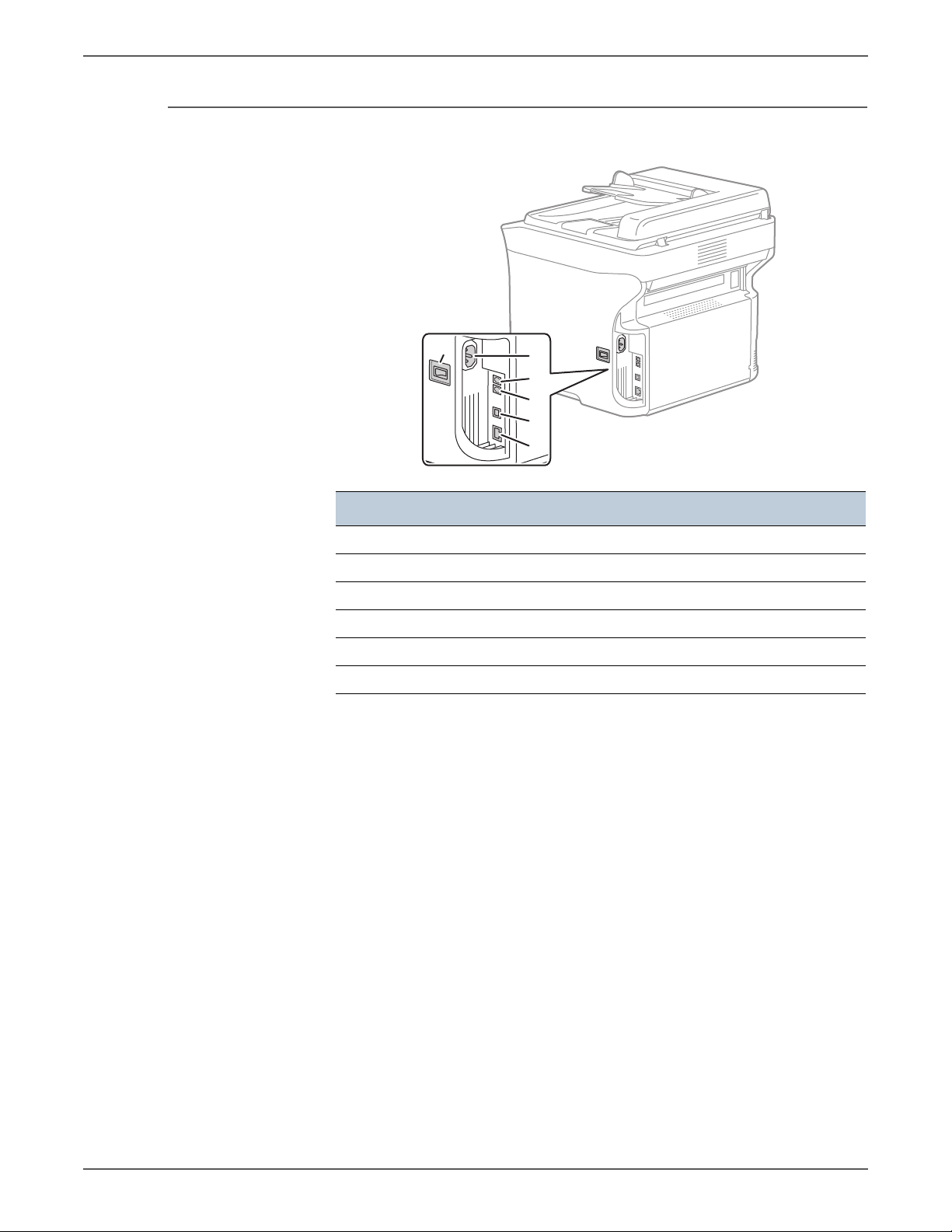
Rear View
s6121mfp-173
2
3
4
5
6
1
General Information
Item Description
1Power switch
2 Power cord connection
3 Fax Phone line out (Phaser 6121MFP/N and /D only)
4 Line out jack (Phaser 6121MFP/N and /D only)
5USB cable port
6 Network/Ethernet connections (Phaser 6121MFP/N and /D only)
Phaser 6121MFP Service Manual 1-5
Page 28
General Information
s6121mfp-175
1
2
3
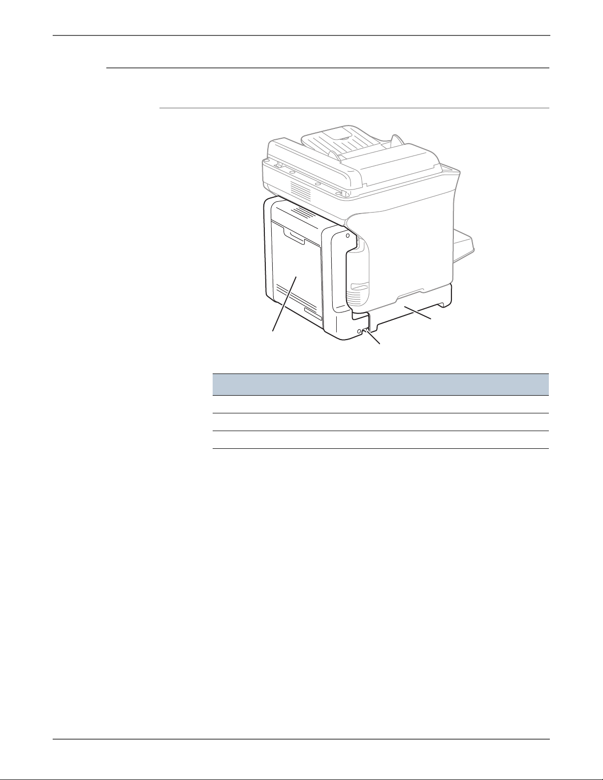
Options
Duplex Unit
Item Description
1Duplex Unit Optional Base
2 Release Lever
3Duplex Unit
1-6 Phaser 6121MFP Service Manual
Page 29

Lower Feeder Tray
2
1
s6121mfp-176
General Information
Item Description
1 Lower Feeder Unit
2 500-Sheet Feeder with Tray Cover
Phaser 6121MFP Service Manual 1-7
Page 30
General Information
s6121mfp-177
43
21
5
8
11
15149 131276
10
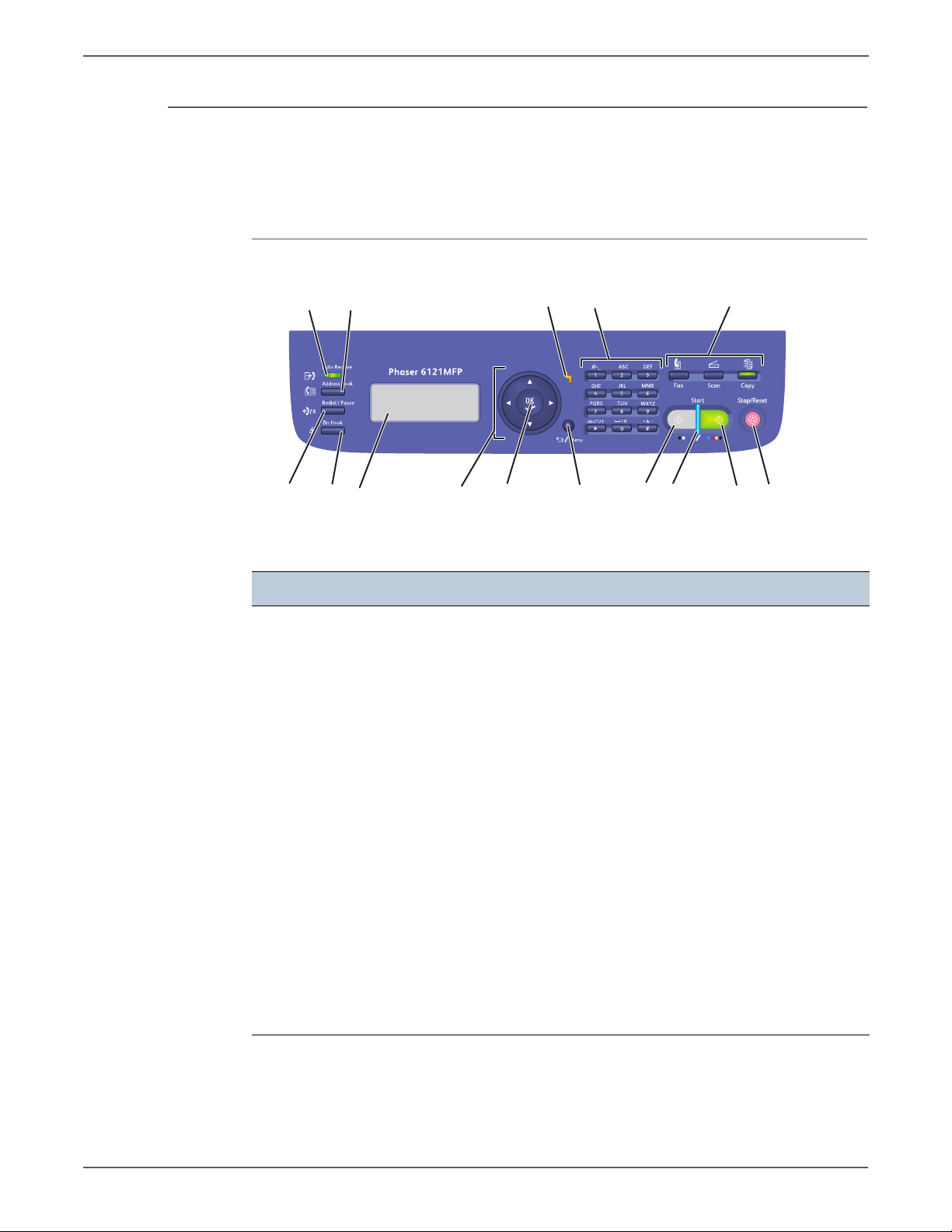
Control Panel
The Control Panel consists of multiple LEDs, a display, and several function
buttons. These buttons are used to navigate the menu system, perform functions,
and select modes of operation.
Control Panel Button Descriptions
Left side: Fax Controls Middle Right side
1. Auto Receive LED
Remains lit while the
automatic receive function
is on. Blinks when there is a
stored fax in memory.
2. Address Book button
Press to access the printer’s
address book, fax numbers,
and E-mail addresses.
3. Redial / Pause button
Recalls the last number
dialed. Inserts a pause
when a fax number is
dialed.
4. On Hook button
When the fax line is shared
with a telephone, pressing
On Hook before sending or
receiving disables the
telephone extension.
5. Menu Display window
Displays settings, menus,
and messages
6. Navigation / Menu buttons
Up / Down arrow buttons
move through menus,
options.
Back / Forward arrow
buttons move left and right
through menus, options.
7. OK (confirm) button
Press to select the setting
that is currently displayed.
8. Alert indicator
When lit, indicates an error
condition or warning.
9. Back/Menu button
Press to go to the System
Menu, cancel an entered
character, or return to the
previous screen.
10.Alphanumeric keypad
Use to enter information.
11.Mode buttons
Press to select Fax, Scan, or
Copy mode.
12.B&W Start button
Starts a fax or B&W copy
or scan.
13.Ready indicator
Lights up when it is OK to
press the Start button to
copy, scan, or fax.
14.Color Start button
Starts a color copy or scan.
15.Stop/Reset button
Press to return to the
default mode main menu;
cancel current print/copy/
fax job.
1-8 Phaser 6121MFP Service Manual
Page 31

Maintenance Items
Note
s6121mfp-172
2
3
4
1
General Information
Routine maintenance items are parts or assemblies that require periodic
replacement. These items are typically customer replaceable (CRU).
The listed items have limited life and require periodic replacement.
Maintenance Items
Item Print Life
Transfer Roller Up to 50,000 pages
Fuser Up to 50,000 pages
Imaging Unit Approximately 30,000 pages
Tray Separator Pad Up to 50,000 pages
ADF Feed Roller Up to 35,000 pages
ADF Separator Pad Up to 35,000 pages
Print life is based on “typical” office printing and 5% coverage per color on 24
lb. paper. Print life figures are not guaranteed and varies depending on usage
habits. Imaging Unit print life is based on 3-page jobs using letter-size paper.
Item Description
1Transfer Roller
2Fuser
3Imaging Unit
Phaser 6121MFP Service Manual 1-9
4 Toner Cartridge
Page 32

General Information
Consumables
Consumables consist of 4 Toner Cartridges.
Each Toner Cartridge has a CRUM (Customer Replaceable Unit Meter) to record
toner usage information. A CRUM counts the amount of remaining toner. When
toner empty is detected, Life End status is displayed to indicate toner empty.
CMY Toner is not consumed when printing in monochrome mode or when printing
Gray scale. Internal counters track consumables and maintenance life.
Life ratings are based on A-size sheets at 5% coverage.
Print Life
Toner Cartridge
Standard Capacity 1,500 pages 1,000 pages
High Capacity 2,500 pages 2,500 pages
C,M,Y Black
1-10 Phaser 6121MFP Service Manual
Page 33

Specifications
Printer Specifications
General Information
Characteristic Description
Type Desktop full-color laser beam printer
Printing system Laser and electrostatic image transfer to plain paper
Exposure system 2 laser diodes and polygon mirror
PC drum type OPC (organic photo conductor)
Photoconductor
cleaning
Resolution 1200 x 600 dpi, 600 x 600 dpi
Media feeding 6121MFP/S Tray 1: 200 sheets
Developing system Single-element developing system
Charging system DC comb electrode Scorotron system
Image transfer
system
Media separating Curvature separation + Charge-neutralizing system
Fusing system Roller fusing
Media exit system Face down (Output tray capacity: 100 sheets)
Warm-up time Average 30 seconds (return to Ready from Energy Saver)
Print resolution 600 x 600 dpi x 1 bit (Standard)
Custom media sizes Paper width: 92 to 216 mm (3.6" to 8.5")
Blade cleaning system
6121MFP/N/D Tray 1: 200 sheets
Expandable to a two-tray system by
adding optional 500-Sheet Lower
Feeder Unit.
Intermediate transfer belt system
1200 x 600 dpi x 1 bit (Enhanced)
Paper length:
195 to 356 mm (Plain paper)
184 to 297 mm (Thick paper)
Media types Plain paper (60 to 90 g/m2)
Thin card stock 1 (91 to 163 g/m2)
Thick card stock 2 (164 to 209 g/m2)
Postcards
Envelopes
Letterhead
Label stock
Tray capacities Plain paper and letterhead: 200 sheets
Thick stock, postcards, labels, and glossy stock: 50 sheets
Envelopes: 10 sheets
Phaser 6121MFP Service Manual 1-11
Page 34

General Information
Performance Specifications
Characteristic Specification
Copy speed with auto document
feeder
(Phaser 6121MFP/N and /D
printer configurations only.)
Copy resolution 600 x 600 dpi x 1 bit
Scan speed
(Phaser 6121MFP/N or /D printer
configurations only.)
Scan resolution 150 x 150 dpi
Fax M ode m spe ed
(Phaser 6121MFP/N or /D printer
configurations only.)
Fax T X speed
(Phaser 6121MFP/N or /D printer
configurations only.)
Color: 3 cpm (600 x 300 dpi)
Monochrome: 10 cpm (600 x 300 dpi)
Monochrome: 20 cpm (300 x 300 dpi)
Color:
600 x 600 dpi: 9.94 mm/second
600 x 300 dpi: 19.88 mm/second
Monochrome:
600 x 600 dpi: 29.81 mm/second
600 x 300 dpi: 59.62 mm/second
300 x 300 dpi: 119.5.25 mm/second
300 x 300 dpi
V.34 (up to 33.6 k bps)
3 seconds/page (at V.34)
1-12 Phaser 6121MFP Service Manual
Page 35

Controller
General Information
The following table lists controller functionality for the Phaser 6121MFP/S.
Characteristic Description
Memory RAM (128 MB)
Flash ROM (4 MB for F/W)
Interface USB 2.0 compliant
Hard Disk Not supported
Support Microsoft Windows Vista, Windows XP (Service Pack 2 or
later), Windows XP Professional x64, Windows Server
2003, Windows Server 2003 x64 Edition, Windows 2000
(Service Pack 4 or later)
Mac OS X (10.2.8 or later; We recommend installing the
latest patch)
The following table lists controller functionality for the Phaser 6121MFP/N/D.
Characteristic Description
Standard memory RAM (128 MB)
Flash ROM (4 MB for F/W)
Fax (6 MB )
Hard Disk Not supported
Interface USB 2.0 (High Speed) compliant, 10Base-T/100Base-T
Ethernet, Host USB (for scan to USB memory)
PSTN (Fax) Connector Two RJ11 (Phone and Line) for US models; phone port is
closed in European models
Support Microsoft Windows Vista, Windows XP (Service Pack 2 or
later), Windows XP Professional x64, Windows Server
2003, Windows Server 2003 x64 Edition, Windows 2000
(Service Pack 4 or later)
Mac OS X (10.2.8 or later; We recommend installing the
latest patch)
Phaser 6121MFP Service Manual 1-13
Page 36

General Information
Electrical Specifications
Characteristic Specification
Power Supply Voltage/Frequency
Line Voltages 110 – 127 VAC
220 – 240 VAC
Frequency Range 50 – 60 Hz
Current Capacity 110 V Engine: < 9 A
220 V Engine: < 5 A
Power Consumption (with all options, 110 or 220 V)
Power Saver Mode 10W or less
Standby Mode (Fuser On) 80W or less
Color Continuous Printing 300W or less
B/W Continuous Printing 396W or less
Maximum Value 1060 W or less
Environmental Specifications
Characteristic Specification
Te mp e ra tu re
Operating 10 to 35° C (50 to 95° F)
Storage -20 to 55° C (-4° to 131° F)
Humidity (% RH)
Operating 10 to 85% RH
Storage 35 to 85% RH
Operating Altitude
Acoustic Noise LWA(B) Sound Pressure (dBA)
0 to 2,500 meters (8,000 feet)
Printing 52
Standby 35
1-14 Phaser 6121MFP Service Manual
Page 37

Media and Tray Specifications
Auto Document Feeder
Characteristic Specification
Paper Size A4 (210 x 297 mm / 8.2 x 11.5 in.)
Paper Type (Weight) Plain (50 – 110 gsm / 16 – 34 lb.)
Loading Capacity Holds up to 35 standard sheets
Paper Tray 1 – Multi-purpose
Characteristic Specification
General Information
Letter (8.5 x 11 in.)
Legal (8.5 x 14 in.)
Custom size range:
W: 140 – 216 mm, H: 148 mm – 356 mm
Paper Size A4 (210 x 297 mm / 8.2 x 11.5 in.)
A5 (148 x 210 mm / 5.8 x 8.2 in.)
B5 (ISO) (176 x 250 mm)
Envelopes C6 (114 x 162 mm)
Envelopes DL (110 x 220 mm)
Executive (7.25 x 10.5 in.)
Foolscap (8 x 13 in.)
Government Legal (8.5 x 13 in.)
Government Letter (8 x 10.5 in.)
Letter (8.5 x 11 in.)
Letter Plus (8.5 x 12.69 in.)
Legal (8.5 x 14 in.)
SP Folio (210 x 330 mm)
Statement (5.5 x 8.5 in.)
UK Quarto (203 x 254 mm / 8 x 10 in.)
Custom size range:
W: 92 – 216 mm (3.6 – 8.5 in.)
H: 184 – 356 mm (7 – 14 in.)
Paper Type (Weight) Plain (60 – 90 gsm / 16 – 24 lb.)
Letterhead
Thin Card Stock (91 – 162 gsm / 30 – 60 lb. Cover)
Thick Card Stock (164 – 209 gsm / 61 – 80 lb. Cover)
Envelopes (DL and C6 sizes only)
Labels
Loading Capacity 200 sheets (20 lb.)
Phaser 6121MFP Service Manual 1-15
Page 38

General Information
First Print Output Time (FPOT)
500-Sheet Feeder (Tray 2)
Characteristic Specification
Paper Sizes A4, Letter
Paper Type (Weight) Plain (60 – 90 gsm / 16 – 24 lb.)
Loading Capacity 500 sheets (20 lb.)
Duplex Unit
Characteristic Specification
Paper Sizes A4, Letter
Paper Type (Weight) Plain, Letterhead (60 – 90 gsm / 16 – 24 lb.)
First Print Output Time is defined as a time from when the engine receives a Start
signal in Ready state, until a single page is printed and delivered to the output tray.
The following conditions are applied:
• The Controller does not keep the print engine waiting
• The printer is at Ready mode
• Paper is A size Short Edge Feed (SEF)
• Process control time is not included
Tray 1
Size
A4/Letter
Simplex
A4/Letter
Duplex
Legal Simplex < 33 sec. < 11 sec. N/A N/A N/A N/A
Legal Duplex N/A N/A N/A N/A N/A N/A
Normal paper
color mono color mono color mono
< 21 sec. < 11 sec. < 21 sec. < 11 sec. < 28 sec. < 19 sec.
< 33 sec. < 23 sec. < 33 sec. < 23 sec. N/A N/A
Tray 2
Normal paper
Tray 1
Thick paper
1-16 Phaser 6121MFP Service Manual
Page 39

First Copy Output Time
10 cm
(3.9 in.)
10 cm
(3.9 in.)
27.8 cm
(10.9 in.)
71 cm
(27.9 in.)
67.3 cm
(26.5 in.)
60.5 cm
(23.8 in.)
s6121mfp-178
First Copy Output Time (FCOT) is defined as the time when the Start button is
pressed until the trail edge of the first copied media passes the printer Exit Roller.
The following conditions are applied:
• The Controller does not keep the print engine waiting.
• The printer is at Ready mode (Laser Unit Motor Off, Fuser Ready).
• Paper is A size Short-Edge Feed (SEF).
• Media: Media feed from the standard media tray.
Mode FCOT (second) Platen FCOT (second) ADF
Color 57.0 sec. 45.0 sec.
Mono 23.0 sec. 19.0 sec.
Physical Dimensions and Clearances
General Information
Minimum Clearances
Minimum clearances for the Phaser 6121MFP/S.
Phaser 6121MFP Service Manual 1-17
Page 40

General Information
(
)
s6121mfp-180
2°2°
Minimum clearances for the Phaser 6121MFP/N
81.4 cm
(32.0 in.)
60.5 cm
(23.8 in.)
79.4 cm
(31.3 in.)
10 cm
(3.9 in.)
Mounting Surface Specifications
These specifications apply to any printer used as a table-top printer.
Mounting surface flatness must be within the specified range. The printer must
not be tipped or tilted more than 2 degrees.
10 cm
3.9 in.
25.4 cm
(10.0 in.)
s6121mfp-179
1-18 Phaser 6121MFP Service Manual
Page 41

Information Pages
Configuration Page
General Information
Known problems that occur as a result of exceeding the mounting surface
specifications are:
• Color-to-Color mis-registration, primarily in the horizontal (laser scan)
direction.
• A smear or line of toner approximately 40 mm from the trailing edge of the
print.
Print the Configuration Page from the Control Panel, System Menu > Print Config
Page. The Configuration Page includes this information.
Configuration Page Information
General Description Detail Description
Title Prints Title of the document
Supplies Status Shows the status of toner cartridges and Imaging
Unit, and displays the remaining life of each as a
percentage.
Coverage Information Shows coverage information for each toner
cartridge as a percentage.
Counter Information Shows usage data by job type.
General Information Xerox Serial Number, Engine Serial Number,
Installation Date, Engine Firmware, Boot Code,
Controller Firmware, Language, Energy Saver
Mode, Toner Low Prompt, Toner Out Action, Initial
Mode, Size Mismatch, Tray type and size
Machine Defaults Shows the default settings for copying, scanning,
and faxing.
Network Settings Network Interface, Host Name, DHCP/BOOTP,
IP Address, Subnet Mask, Gateway Address, MAC
Address, DNS Addresses, and the status of
Bonjour, HTTP, SNMP, FTP, and IPP
Fax Settings Fax Number, Tone/Pulse, No. of Ring, Line
Monitor, Header, Footer, Fax PTT Country, Send
Speed, Receive Speed, ECM Mode
Email Settings Sender Name, Sender’s Email, SMTP Protocol,
SMTP Server Address, SMTP Port No., SMTP
Authentication, POP Before SMTP, POP3 Server
Address, LDAP Protocol, LDAP Server Address,
LDAP Port No.
Phaser 6121MFP Service Manual 1-19
Page 42

General Information
1-20 Phaser 6121MFP Service Manual
Page 43

Theory of Operation
In this chapter...
• Operational Overview
• Paper Path of the Printer
• Major Assemblies and Functions
• Media Handling
Chapter
2
Page 44

Theory of Operation
Operational Overview
Print Process
The Phaser 6121MFP is a full-color laser printer that utilizes electrophotographic
recording principals to place a full color image onto the print media. The system
contains a drum and developing unit that places the toner image of each color
onto print media producing full-color prints.
The following illustration shows the Phaser 6121 print cycle.
Paper Separation
2nd Image Transfer
Transfer Belt
Cleaning
1st Image Transfer
Photo
Developing
Printer Image
Processing
The Phaser 6121 print process consists of these steps:
1. Exposure
The surface of the Drum is irradiated with the laser light and an electrostatic
latent image is formed.
2. Developing
The toner, negatively charged, is attracted onto the electrostatic latent image
formed on the surface of the Drum.
Conductor
Laser Exposure
PC Drum Cleaning
Photo Conductor Charging
s6121mfp-103
2-2 Phaser 6121MFP Service Manual
Page 45

Theory of Operation
s6121mfp-104
Photo Conductor
s6121mfp-105
Transfer Belt
2nd Transfer Roller
Charge Neutralizing Cloth
Charge Neutralizing Cloth
A DC negative bias voltage is applied to the Developing Roller, thereby
preventing toner from sticking to the background image portion.
3. Image Transfer to Belt
A DC positive voltage is applied to the backside of the Transfer Belt to attract
the visible, developed image from the surface of the Drum.
4. Image Transfer to Media
A DC positive voltage is applied to the backside of the paper to attract the
visible, developed image on the surface of the Transfer Belt to the media.
5. Paper Separation
A Charge Neutralizing Cloth is provided on the guide plate to neutralize the
charge.
Phaser 6121MFP Service Manual 2-3
Page 46

Theory of Operation
Transfer Belt
2nd Transfer Roller
s6121mfp-106
s6121mfp-280
Engine Control Board
Image Processor Board
CPU
Control Panel
Scanner
TC/Y TC/KTC/CTC/M
Image Processing
Fusing
Image Process
Paper Pick-Up/
Transport
Laser Unit
Image Bus Line
Control System Line
FAX
Power Supply/
High Voltage
6. Transfer Roller Cleaning
The residual toner left on the surface of the Transfer Roller is removed by an
alternating DC charge that transfers the waste toner back to the Transfer Belt
for collection by the Transfer Belt cleaning blade.
7. Transfer Belt Cleaning
A charge is applied to the Transfer Belt. By potential difference, residual toner
on the surface of the Transfer Belt is collected for cleaning. The toner scraped
off the surface of the photo conductor is collected in the Imaging Unit.
8. Fusing
Toner is permanently fused to the paper by the combination of heat and
pressure applied by the Fuser.
System Control
The following diagram shows the major operating components and their basic
connection to each other.
2-4 Phaser 6121MFP Service Manual
Page 47

Paper Path of the Printer
s6128mfp-107
1
2
3
Print Engine Paper Path
The print media is supplied from Tray 1 or the optional Tray 2, and is transported
into the printer along the paper path as shown in the diagram.
Theory of Operation
Item Description
1Output Tray
2Tray 1 (MPT)
3 Tray 2 (Optional 500-Sheet Feeder)
Phaser 6121MFP Service Manual 2-5
Page 48

Theory of Operation
s6121mfp-378
Automatic Document Feeder (ADF) Print Path
Sensors
The printer contains sensors of various types that perform a variety of functions.
One group of sensors track the progress of the paper along the paper path, and
detects if a jam occurs. Other sensors detect the presence of the Toner Cartridges,
stop printer activity if a door is open (interlock), detect the presence of media in
the trays, and monitor the fusing temperature.
For an overview of sensors in the printer, see “Sensors and Switches” on page 2-11.
Sensor Types
The types of sensors used vary with function. In general, there are three types in
use: photo sensors, microswitches, and thermistors.
Photo Sensors
Two types of photo sensors are used, photo-reflective and photo-receptive. Photoreflective sensors use light reflected back from an object to detect its presence.
Photo-receptive sensors use an actuator or the object itself to block the light path
to detect an object or condition.
Photo-reflective sensors have the light emitter and light receiver aligned on a
single surface. Output of the photo-receptor is High (> +4.5 V) when light is being
reflected back and Low (< +.3 V) when it isn’t. Photo-receptive sensors consist of a
LED in one arm of a U-shaped holder, and a photo-transistor in the other arm.
When the sensing area is vacant, nothing is between the arms of the sensor, light
falls on the photo-receptor sending the signal High. If the light is interrupted, the
photo-transistor goes Low.
Microswitches
Microswitches are used primarily as cover interlocks. They are in a normally open
state, and close when actuated. Microswitches employ hooks or catches for
retention in the bracket or frame.
2-6 Phaser 6121MFP Service Manual
Page 49

Thermistors
s6128mfp-108
1
2
3
4
Thermistors have a known value of resistance whose value varies with
temperature. Used primarily in the Fuser for temperature sensing.
Sensors in the Paper Path
The following illustration identifies the various sensors located along the paper
path of a printer equipped with the Lower Feeder Unit and Duplex Unit. Error
reporting is dependent on these designators. Error detection is based on paper
transport timing through the sensing area.
Theory of Operation
Item Description
1Exit Sensor
2 2nd Image Transfer Retraction Position Sensor
3 Registration Sensor
4 Media Empty Sensor
Phaser 6121MFP Service Manual 2-7
Page 50

Theory of Operation
s6121mfp-109
1
2
Automatic Document Feeder (ADF) Sensors
Item
Description
1 Paper Feed Sensor
2ADF Tray
2-8 Phaser 6121MFP Service Manual
Page 51

Major Assemblies and Functions
s6121mfp-110
Scanner
Auto Document Feeder
Imaging Unit
Toner Cartridges
Laser Unit
Paper Feed Unit
2nd Image Transfer Section
Fuser
1st Image Transfer Section
The location of the system’s primary functional components is shown.
Theory of Operation
Phaser 6121MFP Service Manual 2-9
Page 52

Theory of Operation
Scanner Control Board
LVPS
HVPS
Fax Board
Engine Control
Board
s6121mfp-360
Main Engine Component Overview
Board Locations
2-10 Phaser 6121MFP Service Manual
Page 53

Sensors and Switches
s6121mfp-227
Paper Feed Sensor
Registration Sensor
Exit Sensor
Temperature/Humidity Sensor
Registration
Sensor
Rack Position Sensor
Front Door Switch
Main Power Switch
Contact Switch
Paper Full
Sensor
2nd Image Transfer
Retraction/Position
Sensor
Theory of Operation
Phaser 6121MFP Service Manual 2-11
Page 54

Theory of Operation
s6121mfp-361
Ozone Fan
LVPS Fan
Exit Tray Cooling Fan
Scanner Motor
Rack Motor
Developing Motor
Tray 1 Paper Feed Solenoid
Cleaning Blade
Pressure/
Retraction
Solenoid
Conveyance Solenoid
2nd Image Transfer
Pressure/Retraction
Solenoid
Main Motor
Motors, Fans, and Solenoids
2-12 Phaser 6121MFP Service Manual
Page 55

Fuser
s6121mfp-111
Thermostat
Exit Sensor (PS7)
Pressure Roller
Thermistor (TH1)
Heater Lamp
Fusing Roller
s6121mfp-162
Theory of Operation
Functional components of the Fuser appears below.
Fuser Drive
The Fuser is driven by the Main Motor.
Phaser 6121MFP Service Manual 2-13
Page 56

Theory of Operation
Fuser Temperature Control
To fuse the image on the media, the heater lamps are turned On and Off as
necessary to bring the fusing temperature to an appropriate level. Thermistors are
used to detect the surface temperature of the Fuser roller.
Warm-up Control Wait Control Print Control Wait Control
Printing
Temperature
Warm-up
Complete
Temperature
s6121mfp-113
Warm-up Control
Control is provided until the Fuser roller reaches the predetermined level.
Control Start Timing
• The power switch is turned On.
• A malfunction or media misfeed is reset.
• The main body leaves the power save mode.
• A door is closed.
Control Termination Timing
• The Fuser roller reaches a predetermined temperature.
• A malfunction or media misfeed is reset.
•A door is opened.
2-14 Phaser 6121MFP Service Manual
Page 57

Control Start Decision
Either of the following two control start decisions is made according to the
temperature detected by the temperature/humidity sensor. The fusing
temperature during the print cycle varies depending on the type of the start
control carried out, either low temperature or ordinary start control.
Wait Control
Control is provided to ensure that the temperatures at different parts of the Fuser
reach a constant level during the wait state.
Theory of Operation
Control Start Decision Environment on Start
Low temperature start control The temperature/humidity sensor detects a
temperature lower than the predetermined
value.
Ordinary start control The temperature/humidity sensor detects a
temperature equivalent to, or higher than, the
predetermined value.
Control Start Timing
• At the end of the warm-up control.
• At the end of the post-print cycle control (print start control).
Control Termination Timing
• The front cover is opened and closed.
• A malfunction or media misfeed occurs.
Print Control
To ensure a good fixing level and light transmission performance, the fusing speed
and Fuser Roller temperature are controlled.
Control Start Timing
A print request is received.
Control Termination Timing
A malfunction or media misfeed occurs.
Phaser 6121MFP Service Manual 2-15
Page 58

Theory of Operation
Print Control Temperatures
• The Fuser Roller temperature is set according to the type of media, main body
interior temperature (as measured by the temperature/humidity sensor), and
warm-up start decision.
• For types of media other than plain paper, the fusing speed is controlled at the
1/2 speed.
Print Control Temperature Adjustments
• The temperature during print control is adjusted using the menu available
from the control panel.
• Adjustment steps are 0°C, -5°C, and -10°C.
Protection Against Abnormally High Temperature
The machine provides protection at three different stages to prevent abnormally
high temperature of the Fuser.
Soft Protection
If the Thermistor (TH1) detects a temperature exceeding a predetermined value,
the malfunction code representing abnormally high temperature is displayed. At
this time, the power supply line is shut down.
If the temperature of the Fusing Roller does not reach a predetermined value
within a predetermined period of time after the start of the warm-up cycle, the
power supply line is shut down.
Hard Protection
If the CPU overruns and the output level of the CPU of the Mechanical Control
Board becomes a HIGH or LOW level, and not a pulse output, and a predetermined
temperature or higher is detected, a circuit within the Mechanical Control Board
turns OFF the relay to shut down each power supply line.
Thermostat Protection
If a faulty Thermistor (TH) prevents detection of abnormally high temperatures by
soft protect or hard protect, the thermostat operates at a predetermined
temperature to shut down the power supply line.
2-16 Phaser 6121MFP Service Manual
Page 59

PPM control
s6121mfp-114
Scanner Motor (M101)
Exposure Unit
PPM (page per minute) control prevents the edge temperature of the heating
roller from increasing during a multi-print cycle using smaller sized media. The
distance between fed sheets is increased according to the number of printed
pages that are to be produced and the media length. This evens out the
temperature of the heating roller and thus stabilizes fusing performance of the
printed toner image.
The PPM control is provided at 20 ppm for a multi-print cycle of producing 20
pages. The number of printed pages per minute is established as detailed below
for each media size for the 21st and subsequent pages.
No PPM control is provided for a multi-print cycle of color printing, as it is 1/4 of
the monochrome printing.
Theory of Operation
Media Conditions PPM
A5, invoice 14 ppm
Media having a narrower width and longer length than above 8 ppm
Scanner
Scanner components include:
• Scanner Motor and Drive Belt
•Platen Glass
•Scanhead
Functional components of the Scanner are illustrated below.
Phaser 6121MFP Service Manual 2-17
The Scanner does not include sensors for determining the size of the original
document. Original media size settings are made on the Control Panel.
Page 60

Theory of Operation
s6121mfp-115
Home Position (Stand-by Position)
Reference
Position
Original Reading
Start Position
Original Reading
Finish Position
Scanner Stop
Position
Shading
Original Reading
Reference Position Detection
Scan from Platen
The Scanner performs these steps during a scan of an original placed on the
platen.
• The exposure unit moves from the home position (stand-by position) reading
the calibration sheet to make a shading compensation.
• The exposure units moves to the stand-by position.
• Original image reading starts from the start position of original reading.
• When the original reading completes, it moves to scanner stop position.
• After the reading completes, the exposure lamp lights OFF and it moves to the
stand-by position.
• It moves again to detect the reference position.
• It moves to the stand-by position and stops there.
2-18 Phaser 6121MFP Service Manual
Page 61

Scan from ADF
s6121mfp-116
ADF Reading
Position
Home Position (Stand-by Position)
Reference Position
Shading
Reference Position Detection
Original
Reading
The Scanner performs these steps during a scan of an original placed on the
platen.
• The exposure unit moves from the home position (stand-by position) reading
• The exposure units moves to the stand-by position.
• It moves to ADF reading position and original image reading starts.
• After the reading completes, the exposure lamp turns OFF and moves to the
• After it moves again to detect the reference position, it moves to the stand-by
Theory of Operation
the shading sheet to make a shading compensation.
stand-by position.
position and stops.
Phaser 6121MFP Service Manual 2-19
Page 62

Theory of Operation
s6121mfp-117
Semiconductor Laser
SOS Sensor
Polygon Mirror
G2 Lens
SOS Mirror
Return Mirror
s6121mfp-118
Photo
Conductor
Polygon Mirror
Laser Diode
Beam A
Photo Conductor Surface
Beam B
Return Mirror
G2 Lens
G1 Lens
Laser Unit
The Laser Unit in the Phaser 6121 printer has two laser diodes. The laser diode
control circuitry adjusts the light intensity for each beam automatically. Image
data is transmitted to the laser diodes in the Laser Assembly as digital signals. The
laser diodes convert the image data from digital signals to optical signals. The
Laser Assembly monitors and adjusts the intensity of the laser beams to attain a
stable electrostatic image. The Laser Assembly is replaced as a complete assembly.
Functional components within the Laser appear in the following.
Imaging Unit Exposure
The surface of the Imaging Unit is irradiated with laser light to form an
electrostatic latent image. The polygon mirror has four faces. The two-beam laser
array consists of two laser diodes arranged vertically. Two lines are scanned
through a single face of the polygon mirror.
2-20 Phaser 6121MFP Service Manual
Page 63

Laser Write Process
s6121mfp-281
Photoconductor
Semiconductor Laser
SOS Board
Polygon Motor
1. The laser light strikes the polygon mirror.
2. The four-sided polygon mirror rotates at high speeds driven by the Polygon
Motor.
3. The Start-of-Scan (SOS) Sensor monitors laser light emission and initiates
timing for each line of the scanning process.
Theory of Operation
Phaser 6121MFP Service Manual 2-21
Page 64

Theory of Operation
Laser Write Timing
When a Ready signal is detected after the print cycle begins, a Laser On signal is
output from the Engine Control Board. The Laser On signal triggers each laser
diode illuminating the SOS Board and generating an SOS signal. The SOS signal is
used to synchronize the timing at which the laser write each scan line.
The print start position in the CD direction is determined by the CD Print Start
signal (/HSYNC) that is output from the Image Processor Board and the width of
the paper.
The print start position in the FD direction is determined by the Image Write Start
signal (TOD) that is output from the Image Processor Board and the length of the
paper. The laser emission area is determined by the paper size. The area of 4 mm
on both the leading and trailing edges of the paper is, however, the void image
area.
/HSYNC
/VIDEO
4 mm
4 mm
4 mm
/VIDEO /TOD
4 mm
s6121mfp-119
2-22 Phaser 6121MFP Service Manual
Page 65

Imaging Unit
s6121mfp-120
Transfer Belt
Cleaning Blade
s6121mfp-123
Theory of Operation
The Imaging Unit contains the photo-conductive drum, cleaning blade, transfer
belt, transfer roller, and waste toner reservoir.
The photo-conductive drum is driven by the Main Motor through a series of gears.
When the Main Motor is energized, it turns the drive gear, which in turn rotates the
drum.
Phaser 6121MFP Service Manual 2-23
The cleaning blade is pressed against the drum to remove excess toner. Waste
toner is stored in the Imaging Unit.
Page 66

Theory of Operation
s6121mfp-124
Cleaning Blade
s6121mfp-282
Grid Mesh
An electrical charge is applied to the drum by an electrode mounted near the
drum. This charge attracts toner from the Toner Cartridge developer roller. The
image stabilization control process controls the grid voltage (Vg) applied to the
electrode’s grid mesh.
Imaging Unit Life
A counter tracks the number of prints since the last detection of a new Imaging
Unit. As this count nears its maximum value, the system generates a warning
message. When the count reaches the maximum value, a replacement error is
generated. The counter is reset following the detection of a new Imaging Unit.
The system checks for a new Imaging Unit when the Power Switch is turned On or
the front door is closed. If a new Imaging Unit is detected, the image stabilization
sequence is carried out.
The life counter is reset when a new Imaging Unit is detected. When a
predetermined number of printed pages are produced after the life value has been
reached, the machine displays a Imaging Unit replacement message.
2-24 Phaser 6121MFP Service Manual
Page 67

Toner Cartridge
s6121mfp-126
Supply Section
Developer
Roller
Supply Roller
Hopper Section
s6121mfp-127
Theory of Operation
The system employs four Toner Cartridges (CMYK) installed in a revolving Toner
Cartridge Rack that positions each cartridge’s developer roller over the Drum. A
cross section of the Toner Cartridge showing functional components follows.
1. Toner stored in the hopper is moved into the toner supply portion by the
rotation of the Toner Cartridge rack
2. Toner in the toner supply portion is conveyed by the supply roller onto the
developing roller.
3. Toner then sticks to the electrostatic latent image formed on the surface of
the photo conductor drum. That part of toner left on the surface of the
developing roller is returned to the toner supply portion.
Phaser 6121MFP Service Manual 2-25
Page 68

Theory of Operation
s6121mfp-283
Bias Contact Point
4. To attract toner to the drum, a developing bias voltage (Vb) that includes both
DC (-) and + AC components is applied to the developing roller during
development. The AC component is applied only during development. The
developing bias voltage (Vb) supplied by the High Voltage Power Supply is
applied to the developing roller at the contact point shown below.
Developer Roller Drive
The Developer Roller is driven by the Developing Motor and intermediate gears.
Developing Roller
Intermediate Gear
Developing Roller Drive Gear
Developing Motor (M3)
s6121mfp-128
2-26 Phaser 6121MFP Service Manual
Page 69

When the Toner Cartridge Rack is stationery at the developing position, the
s6121mfp-130
Developer Roller drive gear meshes with intermediate gears allowing the
Developing Motor to engage the roller.
Toner Cartridge Rack
The Toner Cartridge Rack holds the four Toner Cartridges and rotates to position
each cartridges’ Developer Roller in the developing position. The rack is driven by
the Rack Motor.
Theory of Operation
The Toner Cartridge Rack has three stop positions driven by the Rack Motor: the
standby (reference) position, the developing position, and the cartridge
replacement position.
• The standby position is the Toner Cartridge Rack position when the system
completes a warm-up cycle or waits for a print command.
• The development position is when the Toner Cartridge Rack stops during
development of a specific color of toner.
• The cartridge replacement position refers to the position at which the Toner
Cartridge Rack is stopped for replacement of the Toner Cartridge of a specific
color of toner.
Phaser 6121MFP Service Manual 2-27
Page 70

Theory of Operation
C
M
Y
K
s6121mfp-131
K
Y
0°
C
M
C
M
Y
K
s6121mfp-132
M
Y
K
M
K
Y
C
C
s6121mfp-133
90°
The standby position is 28° degrees before the developing position of the
Magenta Toner Cartridge.
The developing position is where the Toner Cartridge Rack is rotated 62° degrees
from the standby position.
The cartridge replacement position is where the Toner Cartridge Rack is rotated
90° degrees from the developing position.
2-28 Phaser 6121MFP Service Manual
Page 71

Monochrome Process Operation
K
Y
C
M
K
Y
C
M
M
Y
K
C
M
Y
K
C
Y
M
K
C
Y
M
K
C
M
Y
CK
M
Y
CK
CK
K
MC
YYM
M
Y
K
C
M
Y
K
C
s6121mfp135
The Toner Cartridge Rack follows these steps for monochrome prints.
1. The Toner Cartridge Rack is stationary at the standby position.
2. When a print request is received from the controller, the Toner Cartridge Rack
is rotated to bring the K Toner Cartridge to its developing position.
3. Development of monochrome printing is started.
4. When the development is completed, the Toner Cartridge Rack is rotated and
brought to a stop at the standby position.
Color Process Operation
The Toner Cartridge Rack follows these steps for color prints.
Theory of Operation
1. The Toner Cartridge Rack is stationary at the standby position.
2. When a print request is received, the Toner Cartridge Rack rotates to place the
Y Toner Cartridge to its developing position.
3. Development of Y is carried out.
4. When development of Y is completed, the Toner Cartridge Rack is rotated to
bring the M Toner Cartridge to its developing position.
5. Development of M is carried out.
6. Similarly, the Toner Cartridge Rack rotates and development of C is carried
out, followed by K.
7. When the development of K is completed, the Toner Cartridge Rack rotates to
the standby position.
Phaser 6121MFP Service Manual 2-29
Page 72

Theory of Operation
s6121mfp-136
Rack Positioning
Sensor (PS5)
Position Detection
The Toner Cartridge Rack stop position for each color of toner is detected by the
Rack Positioning Sensor. Openings around the circumference of the Toner
Cartridge Rack actuate the Rack Position Sensor at each stop position.
The Magenta Toner Cartridge includes a slit for detecting the standby position.
When the Toner Cartridge Rack is rotated, the Rack Positioning Sensor (PS5)
detects the standby position slit. To bring the toner cartridge rack to a stop at the
corresponding developing position, the rack is rotated from the standby position
62° degrees by the Rack Motor.
2-30 Phaser 6121MFP Service Manual
Page 73

Theory of Operation
M
M
Y
Y
K
K
C
C
s6121mfp-137
Detection Of M
Developing Position
Detection Of Y
Developing Position
Detection Of K
Developing Position
Detection Of C
Developing Position
Standby Position
Detecting Position
Rack Positioning Sensor
(In Standby Position)
Direction of Rotation of the
Toner Cartridge Rack
Photo Conductor
When a replacement request is made for a Toner Cartridge, the Toner Cartridge
Rack is rotated 70 degrees from the depleted cartridges’ developing position by
the Rack Motor.
Phaser 6121MFP Service Manual 2-31
Page 74

Theory of Operation
s6121mfp-138
Transfer Belt
Drive Roller
Belt Positioning Sensor
Transport Belt
1st Transfer
Roller
Driven Roller
Toner
Collecting Auger
Cleaning Blade
IDC Sensor
2nd Transfer Roller
Pressure
Slider
Pressure/Retraction Roller
Transfer Belt
The Transfer Belt serves to accumulate the images produced by the four developer
rollers before transferring the composite image to the media with the Transfer
Roller. Components of the Transfer Belt appear below.
In addition to the Transfer Belt, a Transfer Roller (sometimes referred to as the 2nd
Transfer Roller) transfers the composite image to the media for fusing.
2-32 Phaser 6121MFP Service Manual
Page 75

Transfer Drive
s6121mfp-121
Transfer Belt
Imaging Unit
Photoconductor
1st Transfer Roller
Driven Roller
Transfer Belt Drive Roller
Main Motor
The Transfer Belt and the 2nd Transfer Roller are driven by the Main Motor. The
Transfer Roller Clutch at one end of the (2nd) Transfer Roller engages the Main
Motor drive.
Theory of Operation
Phaser 6121MFP Service Manual 2-33
Page 76

Theory of Operation
s6121mfp-139
Transfer Belt Cleaning
The Transfer Belt Cleaning Blade collects residual toner off the surface of the
Transfer Belt, and a toner collecting auger transfers waste toner to the Imaging
Unit reservoir. The prevention seal is affixed to prevent waste toner from leaking
through a gap above the cleaning blade.
During color printing, an image is formed on the Transfer Belt for each color. The
cleaning blade uses a retraction mechanism to lift off the belt during the printing
process. However, no pressure/retraction sensor is used to trigger cleaning blade
retraction. Instead, the IDC sensor detects a sample image on the Transfer Belt to
control the pressure/retraction operation. During monochrome printing, no
retraction sequence is needed. The cleaning blade is normally in contact with the
Transfer Belt.
2-34 Phaser 6121MFP Service Manual
Page 77

Theory of Operation
s6121mfp-140
s6121mfp-141
1
234
Cleaning Blade retraction operations are driven by the Main Motor, Cleaning Blade
Solenoid, pressure cam, and lever. When the Cleaning Blade Solenoid is energized,
drive from the Main Motor is transmitted to the pressure cam.
The sequence of events to retract the cleaning blade are:
1. Drive from the Main Motor is transmitted to the drive gear.
2. Rotation of the drive gear is transmitted to the pressure cam.
3. When the cleaning blade pressure/retraction solenoid (SD5) is energized, the
half-moon-shaped pressure cam rotates a half turn to push the lever forward.
4. When the lever is pushed forward, the cleaning blade is retracted.
Item Description
1 Cleaning Blade Pressure/Retraction Solenoid
2Cam
3Lever
4Cleaning Blade
Phaser 6121MFP Service Manual 2-35
Page 78

Theory of Operation
s6121mfp-143
Belt Positioning Sensor
Detection Hole B
To return the cleaning blade to the Transfer Belt:
1. The cleaning blade pressure/retraction solenoid (SD5) is energized rotating
the pressure cam a half turn. This pushes the lever backward.
2. When the lever is pushed backward, the cleaning blade is returned. Then, the
cleaning blade is pressed against the transfer belt.
Image development requires the creation of a composite image on the surface of
the Transfer Belt. The leading edge of each color component of the image must
register correctly on the Transfer Belt’s surface. The position of the Transfer Belt is
monitored by the Transfer Belt Position Sensor. The optical sensor detects holes in
the Transfer Belt.
Two detection holes are punched in the Transfer Belt. The image write start
position varies according to the media size. For A4 or smaller media, the image
write start position, as determined by the sensor, is detection hole A. For a media
sizes larger than A4, detection hole B is the reference for the image write start
position.
2-36 Phaser 6121MFP Service Manual
Page 79

Transfer Roller
s6121mfp-144
Theory of Operation
The Transfer Roller (sometimes referred to as the 2nd Transfer Roller) transfers the
developed image from the Transfer Belt to the media. To allow development of the
composite color image on the Transfer Belt, the Transfer Roller retracts from the
belt while the image is developed.
The Transfer Roller retraction operation is performed by the Main Motor, Image
Transfer Solen oid, and Transfer Roller C lutch. When the Image Transfer Solenoid is
energized, drive from the Main Motor is transmitted to the Transfer Roller Clutch.
Phaser 6121MFP Service Manual 2-37
Page 80

Theory of Operation
Pressure/Retraction Clutch
2nd Transfer Assembly
Ribs
Pressure Slider
2nd Image Transfer Pressure/
Retraction Solenoid (SD4)
s6121mfp-286
Transfer Roller Drive
The Transfer roller is driven through a set of intermediate gears by the Main Motor.
2nd Transfer Roller
Image Transfer
To apply pressure to the Transfer Roller (sometimes referred to as the 2nd Transfer
Roller), the system follows these steps:
1. Drive from the Main Motor is transmitted to the drive gear.
2. Rotation of the drive gear is transmitted to the Transfer Roller Clutch.
3. When the 2nd Image Transfer Solenoid is energized, the Transfer Roller Clutch
rotates a half turn. This moves the Pressure Slider.
4. When the Pressure Slider is moved, the ribs push against the Pressure
Retraction Roller.
5. When the assembly is pushed up, the Transfer Roller presses against the
Transfer Belt.
Main Motor (M1)
s6121mfp-285
2-38 Phaser 6121MFP Service Manual
Page 81

Transfer Roller Retraction
Pressure/Retraction Clutch
2nd Transfer Assembly
Ribs
Pressure Slider
2nd Image Transfer Pressure/
Retraction Solenoid
s6121mfp-287
To retract the Transfer Roller from the Transfer Belt, the system performs the
following steps:
1. When the Image Transfer Solenoid is energized, the Transfer Roller is presses
against the Transfer Belt and the Transfer Roller Clutch rotates a half turn. This
moves the Pressure Slider.
2. When the Pressure Slider moves, the Transfer Assembly, which has been
pushed up by the ribs on the Pressure Slider, lowers.
3. When the Transfer Assembly lowers, the Transfer Roller retracts from the
Transfer Belt.
Theory of Operation
Transfer Roller Cleaning
DC positive and negative transfer bias voltages are alternately applied to the
Transfer Roller. These charges oppose those on the Transfer Belt attracting toner
residue on the Transfer Roller back to the Transfer Belt. The Transfer Belt cleaning
blade collects the waste toner from the belt and stores the waste in the Imaging
Unit.
Transfer Roller cleaning occurs when:
• Power Switch is turned ON.
• Cover is opened and closed.
• A media error occurs during a print cycle.
• A paper empty condition occurs during a print cycle.
• A paper size error occurs during a print cycle.
Phaser 6121MFP Service Manual 2-39
Page 82

Theory of Operation
Apply The Constant Current To
The 1st Transfer Roller
Apply The Constant Current To
The 2nd Transfer Roller
Measure The Resistance Of
The 1st Transfer Roller
Establish The 1st Transfer
Output Voltage
Measure The Resistance Of
The 2nd Transfer Roller
Establish The 2nd Transfer
Output Voltage
Constant
Voltage
Constant
Current
Measure
Resistance
Constant
Current
2nd Transfer Roller
Transfer Belt
Transfer Belt
Drive Roller
1st Transfer Roller
Transfer Belt
Photo Conductor
Ground
HVPS
s6121mfp-146
Process Control
For stable printing, the parameters related to forming both the electrostatic and
toner image are continuously monitored and adjusted by the printer. Parameter
correction and control over the entire printing process is called “process control”.
Two primary process control mechanisms are used by the system, Automatic
Transfer Voltage Control (ATVC) and Automatic Image Density Control (ADC).
Automatic Transfer Voltage Control (ATVC)
ATVC optimizes the transfer output. A constant current flows through each of the
Transfer Rollers. The resistance of each of the 1st Transfer Roller, the Transfer Roller
(sometimes referred to as the 2nd Transfer Roller), and Transfer Belt is measured.
ATVC automatically adjusts the appropriate image transfer output voltage (bias)
that is applied to each Transfer Roller and transfer belt during the print cycle.
Automatic Density Control (ADC)
ADC stabilizes image density to provide accurate tone reproduction. ADC uses the
IDC Sensor and Temperature/Humidity Sensor to monitor system and
environmental parameters to regulate the following:
• Leak detection control
For the clearance between the Drum and Developing Roller, an optimum
2-40 Phaser 6121MFP Service Manual
Page 83

Theory of Operation
s6121mfp-147
IN
OUT
Grid Bias Developing Bias
Developing
Charging
PC
ADC Sensor
Temperature/
Humidity Sensor
ADC Control
1st Transfer Roller
2nd Transfer Roller
ATVC
developing bias voltage is established that prevents leak image or uneven
density.
• IDC Sensor intensity control
Adjustments are made to correct changes in IDC Sensor characteristics due to
changes over time or contamination. The IDC Sensor is a photo-reflective
sensor that emits light from an LED and detects the reflected light returning
from the Transfer Belt. The light emitted from the LED is controlled so that the
reflected light density is constant.
• Reflectance measurement control
The reflectance of the Transfer Belt is measured using the IDC Sensor. The
measurement is taken for one complete revolution of the Transfer Belt. The
measured value is corrected during the intensity adjustment and G-correction
control.
• Toner adherence control
The developing bias voltage value is adjusted to keep constant the amount of
toner sticking to the surface of the Drum with reference to the 100% solid
image.
• Laser intensity adjustment control
Characteristics of the Drum, developing, and charging processes are affected
over time and by the environment. The intensity of the laser light is adjusted
so that fine lines and gradations of a predetermined level are reproduced at
all times.
• G-correction control
A gradation pattern is produced on the surface of the Transfer Belt. The IDC
Sensor measures the density of the pattern and sends the measured result to
the controller for gradation adjustment.
Phaser 6121MFP Service Manual 2-41
Page 84

Theory of Operation
Depending on the state of the system, the process control mechanisms are
activated. Factors for each state are listed in the following table.
Mode Process Control Criteria
Mode 1 ■ When the Power Switch is turned On, the current environmental
readings are different from when the Power Switch was turned
Off.
■ The stored environmental readings taken when Energy Saver
mode was entered differ from those taken when the system woke
from Energy Saver mode.
■ The Power Switch is turned Off and On or Energy Saver mode is
canceled after a predetermined number of printed pages have
been produced.
■ A new Imaging Unit or Toner Cartridge is detected.
Mode 2 The Power Switch is turned Off and On, or Energy Saver mode is
canceled after a predetermined number of printed pages have
been produced.
2-42 Phaser 6121MFP Service Manual
Page 85

Theory of Operation
Mode 2
ADC Intensity Control
Reflectance
Measurement Control
Laser Intensity Control
Mode 1
ATVC Control
Leak Detection Control
ADC Intensity Control
Reflectance
Measurement Control
Control Of The Maximum
Amount Of Toner Sticking
Control Of The Maximum
Amount Of Toner Sticking
Laser Intensity Control
G Correction Control
s6121mfp-288
The process controls invoked and the order in which they occur for each mode
appears below.
Phaser 6121MFP Service Manual 2-43
Page 86

Theory of Operation
Note
Temperature/Humidity Sensor
The Temperature/Humidity Sensor monitors the internal temperature of the
system. It is also used for image stabilization, transfer ATVC, and fusing
temperature control.
There is a Control Panel command which obtains environmental temperature
and humidity levels. However, this command is for internal use only and not
available from the service menus.
s6121mfp-148
2-44 Phaser 6121MFP Service Manual
Page 87

System Thermal Regulation
s6121mfp-149
1
2
3
Fans are the primary means used to limit the rise in internal temperature. Three
fans are controlled by specialized circuity on the Main Board. The following
illustration shows the location and airflow direction of these fans.
Theory of Operation
Item Description
Output Tray Fan Cools the Scanner and output media.
Power Supply Fan Draws cool air across the Power Supply.
Ventilation Fan Recovers toner powder in the Imaging Cartridge and
exhausts the ozone produced to the outside.
Phaser 6121MFP Service Manual 2-45
Page 88

Theory of Operation
Power Supply Fan
The Power Supply Fan cools the system Power Supply and operates at full-speed,
half-speed, or stopped states.
The Power Supply Fan runs at full-speed for:
• A set period of time after the Power Switch is turned On.
• A set period of time after exiting Energy Saver mode.
• At the start of a print cycle (full-speed rotation after a set period of half-speed
rotation).
The Power Supply Cooling Fan runs at half-speed:
• At the end of a print cycle (half-speed rotation following the predetermined
period of time needed for full-speed rotation).
• During half-speed rotation under any condition other than above.
The Power Supply Fan stops when:
• The system enters the Energy Saver mode.
• The Power Switch is turned Off.
Ventilation Fan
The Ventilation Fan cools the system cabinet and operates at full-speed when the
Main Motor is in operation.
Output Tray Fan
The Output Tray Fan cools the Scanner and operates at full-speed, half-speed, or
stopped states according to these conditions:
The Output Tray Fan runs at full-speed:
• A set period of time after the Power Switch is turned On.
• A set period of time after exiting Energy Saver mode.
• At the start of a print cycle (full-speed rotation after a set period of half-speed
rotation).
The Output Tray Fan runs at half-speed:
• At the end of a print cycle (half-speed rotation following the predetermined
period of time needed for full-speed rotation).
•During standby.
The Output Tray Fan stops when:
• During Energy Saver mode.
• During firmware upgrade.
2-46 Phaser 6121MFP Service Manual
Page 89

Waste Toner Collection
s6121mfp-150
Waste toner removed from the Transfer Belt and drum by the cleaning blade is
transferred by two gear driven augers into the Imaging Unit waste toner reservoir.
Theory of Operation
Phaser 6121MFP Service Manual 2-47
Page 90

Theory of Operation
s6121mfp-151
Waste Toner Collection Drive
Waste toner collection augers are driven by the Main Motor.
2-48 Phaser 6121MFP Service Manual
Page 91

Waste Toner Full Sensor
s6121mfp-152
Waste toner near full and full conditions are detected by the waste toner near full
sensor, toner agitating screw, and an internal counter. An agitating auger is used
in the reservoir to provide the maximum waste toner storage capacity. A waste
toner near full condition occurs when light emitted from the sensor LED is
obstructed during its travel through the light guide.
Theory of Operation
Rotation of the toner agitating screw causes the actuator to move up and down
via the float plate, so that the waste toner near full sensor detects “H” and “L”
signals alternately. When the amount of waste toner in the waste toner reservoir
exceeds a predetermined level, the toner agitating screw no longer rotates. This
stops the signal transitions from the waste toner near full sensor indicating a near
full condition.
A waste toner full condition exists when 200 images are reached after a waste
toner near full condition is detected. When the LED light is unblocked following
Imaging Unit replacement, the waste toner full condition is reset.
Phaser 6121MFP Service Manual 2-49
Page 92

Theory of Operation
s6121mfp-153
Media Handling
Tray 1 Feeder
2-50 Phaser 6121MFP Service Manual
Page 93

Tray 1 Drive
s6121mfp-154
Pick Roller
Main Motor (M1)
Tray 1 Pick Solenoid (SD1)
s6121mfp-155
When the Tray1 Pick Solenoid is energized, drive from the Main Motor is
transmitted to the Pick Roller via the Tray 1 Pick Clutch. At the same time, the Lift
Cam is rotated, which raises the Lift Plate. The media is taken up and fed in by the
Pick Roller.
Theory of Operation
Phaser 6121MFP Service Manual 2-51
Page 94

Theory of Operation
s6121mfp-156
Separation Pad
Retard Rollers
Pick-Up Roller
s6121mfp-157
Registration Sensor
The fixed Separation Pad system plus the Retard Rollers are used for paper
separation. This ensures that only one sheet of paper is fed.
Tray 1 Media Detection
Tray media empty/misfeed conditions are detected by the registration sensor.
To reduce the number of detected paper misfeeds, another feed sequence is
carried out if a registration sensor signal transition fails to occur within a
predetermined period of time. If after the second feed attempt media is not
detected, a media empty/misfeed condition is reported.
2-52 Phaser 6121MFP Service Manual
Page 95

Media Size Detection
s6121mfp-165
Output Tray
Theory of Operation
Media size is detected using the Registration Sensor. The length of the media is
determined by the length of time the Registration Sensor remains High indicating
media in the registration section.
If the media size specified by the controller does not match the media size
detected by the Registration Sensor, the system displays an error message on the
Control Panel. The sheet causing the size error continues through the print process
and is output to the tray. Operations for subsequent sheets are specified from the
controller.
Media is transported from the Fuser to the output tray using the Exit Roller. The
Exit Sensor monitors the media output.
For printers without an installed Duplex Unit, the exit roller is driven by the Main
Motor. During 1-sided printing, the exit roller rotates in the forward direction and
feeds the media onto the output tray. If an optional Duplex Unit is attached, the
exit roller is driven by the Duplex Unit.
Phaser 6121MFP Service Manual 2-53
Page 96

Theory of Operation
Paper Feed Roller
Pick-Up Roller
Document Feeder
Transport Motor
s6121mfp-224
Output Tray Full Sensor
The Output Tray Full Sensor monitors output tray status.
Paper Full Sensor
Automatic Document Feeder (ADF)
The ADF feeds documents to the Scanner platen for scanning. The functional
components within the ADF are illustrated below.
Paper Exit Roller
Paper Exit Rollers
s6121mfp-289
2-54 Phaser 6121MFP Service Manual
Page 97

ADF Pick Operation
s6121mfp-225
s6121mfp-112
Paper Feed Roller
Separator Pad
1. The media feed sensor detects media loaded in the document feeder.
2. The document stopper establishes the leading edge position of the document.
The stopper is lowered in the standby state and raised when the document is
taken up and fed in.
3. The document stopper is raised and lowered in synchronism with the raising
and lowering motion of the pick-up roller.
4. The pick-up roller and media feed roller turn to take up and feed the original
properly.
5. The pick-up roller transports the original up to the media feed roller.
6. The ADF Transport Motor drives the pick-up roller and media feed roller
through a gear train.
Theory of Operation
Double feeding of paper is prevented using coefficient of friction between the feed
roller and separator pad.
Single sheet feeding The coefficient of friction on the front side of the paper fed
between the media feed roller and separator pad is equal to that on the backside
of the paper. This allows the media feed roller to transport the paper.
Multiple sheet feeding The coefficient of friction between the paper and
separator pad is greater than that between sheets of paper. This ensures that only
the first sheet of paper is transported by the media feed roller.
Phaser 6121MFP Service Manual 2-55
Page 98

Theory of Operation
s6121mfp-159
Registration Roller 1
Registration Roller 2
Registration Roller
Registration Sensor
Document Feeder Transport Motor (M100)
s6121mfp-166
Document Feeder Transport Motor (M100)
Exit Roller
ADF Transport Operation
ADF Exit Operation
1. The registration roller is rotated by the drive from the ADF Transport Motor
and move the original to the document scanning position.
2. The ADF Transport Motor drives the transport roller through a gear train.
3. Activation of the registration sensor establishes the document scan start
timing.
4. Deactivation of the registration sensor establishes the document scan end
timing and timing to de-energize the ADF Transport Motor.
The exit roller, driven by the ADF Transport Motor, turns to feed the original out of
the ADF. The original is fed onto the output tray.
2-56 Phaser 6121MFP Service Manual
Page 99

Duplex Unit
s6121mfp-164
Switchback Motor
Door Sensor
Transport
Motor (M6)
Loop Sensor (PS13)
Registration
Solenoid (SD7)
Registration Roller
AD Drive Board
Transport Sensor
Transport Roller
Cooling Fan Motor (FM3)
Theory of Operation
The Duplex Unit adds 2-sided print capability to the system. The following
illustrations show the location of components within the Duplex Unit.
Phaser 6121MFP Service Manual 2-57
Registration Roller
Transport Roller
s6121mfp-163
Page 100

Theory of Operation
s6121mfp-169
s6121mfp-170
Duplex Unit Drive
The print engine’s Exit Roller, driven by the Fuser gear assembly during one-sided
operations, feeds media into the Duplex Unit. For duplex operation, the duplex
option lever disconnects drive to the Exit Roller, and engages the Duplex
Switchback Motor.
This reverses the Exit Roller feeding the media into the Duplex Unit.
After entering the Duplex Unit, two Transport Rollers, driven by the Duplex Unit
Transport Motor, move media through the system.
2-58 Phaser 6121MFP Service Manual
 Loading...