

Page 1
Phaser® 6115MFP
Color Laser Multifunction Product
Service Manual
701P45784
Page 2

Phaser®6115MFP
W
Color Laser Multifunction Product
Service Manual
701P45784
First Printing: Jan 2007
arning
The following servicing instructions are for use by qualified service
personnel only. To avoid personal injury, do not perform any servicing
other than that contained in the operating instructions, unless you are
qualified to do so.
Page 3

Service Terms
Not
W
Manual Terms
Various terms are used throughout this manual to either provide additional
information on a specific topic or to warn of possible danger present during a
procedure or action. Be aware of all symbols and terms when they are used,
and always read NOTE, CAUTION, and WARNING statements.
Common Acronyms:
The following list defines the acronyms that may be found in this manual.
ADC: Automatic Density Control FRU: Field Replaceable Unit
BTR: Bias Transfer Roller IPB: Image Processor Board
CTD: Toner Density Control IU: Imaging Unit
ECB: Engine Control Board NCS: Non-Contact Sensor
ESD: Electrostatic Discharge PL: Corresponds to the FRU Parts List.
e
A note indicates an operating or maintenance procedure, practice or
condition that is necessary to efficiently accomplish a task.
A note can provide additional information related to a specific subject or
add a comment on the results achieved through a previous action.
Product Terms
Caution
A caution indicates an operating or maintenance procedure, practice or
condition that, if not strictly observed, results in damage to, or destruction
of, equipment.
arning
A warning indicates an operating or maintenance procedure, practice or
condition that, if not strictly observed, results in injury or loss of life.
Caution: A personal injury hazard exists that may not be apparent. For
example, a panel may cover the hazardous area.
Danger: A personal injury hazard exists in the area where you see the sign.
Phaser 6115MFP Multifunction Product Service Manual iii
Page 4

Symbols Marked on the Product
Hot surface on or in the printer. Use caution to avoid personal
injury.
Do not touch the item.
Use caution (or draws attention to a particular component). Refer
to the manual(s) for information.
iv Phaser 6115MFP Multifunction Product Service Manual
Page 5

Power Safety Precautions
W
Power Source
Disconnecting Power
For 115 VAC printers, do not apply more than 135 volts RMS between the
supply conductors or between either supply conductor and ground. For 230
VAC printers, do not apply more than 254 volts RMS between the supply
conductors or between either supply conductor and ground. Use only the
specified power cord and connector. This manual assumes that the reader is
a qualified service technici an .
Plug the three-wire power cord (with grounding prong) into a grounded AC
outlet only. If necessary, contact a licensed electrician to install a properly
grounded outlet. If the product loses its ground connection, contact with
conductive parts may cause an electrical shock. A protective ground
connection by way of the grounding conductor in the power cord is essential
for safe operation.
arning
Turning the power off using the power switch does not completely deenergize the printer. You must also disconnect the power cord from the
printer’s AC inlet. Disconnect the power cord by pulling the plug, not the
cord.
Moving the Printer
Disconnect the power cord in the following cases:
■ if the power cord or plug is frayed or otherwise damaged,
■ if any liquid or foreign material is spilled into the product,
■ if the printer is exposed to any excess moisture,
■ if the printer is dropped or damaged,
■ if you suspect that the product needs servicing or repair,
■ whenever you clean the product.
Follow these guidelines to avoid injuring yourself or damaging the printer:
■ Do not place any food or liquids on the printer.
■ Turn off the printer and unplug all power cables before moving the printer.
Phaser 6115MFP Multifunction Product Service Manual v
Page 6

■ Always lift the printer from the designated lift points.
s6115-418
Caution
Damage to the printer resulting from improper moving or failure to
repackage the printer properly for shipment, is not covered by the
warranty, service agreement, or T otal Satisfaction Guarantee. The
Total Satisfaction Guarantee is available in the United States and
Canada. Coverage may vary outside these areas; please contact
your local representative for details.
vi Phaser 6115MFP Multifunction Product Service Manual
Page 7

Electrostatic Discharge (ESD) Precautions
Some semiconductor components, and the respective sub-assemblies that
contain them, are vulnerable to damage by Electrostatic discharge (ESD).
These components include Integrated Circuits (ICs), Large-Scale Integrated
circuits (LSIs), field-effect transistors and other semiconductor chip
components. The following techniques will reduce the occurrence of
component damage caused by static electricity.
Be sure the power is off to the chassis or circuit board, and observe all other
safety precautions.
■ Immediately before handling any semiconductor components assemblies,
drain the electrostatic charge from your body. This can be accomplished
by touching an earth ground source or by wearing a wrist strap device
connected to an earth ground source. Wearing a wrist strap will also
prevent accumulation of additional bodily static charges. Be sure to
remove the wrist strap before applying power to the unit under test to
avoid potential shock.
■ Do not remove a replacement component or electrical sub-assembly from
its protective package until you are ready to install it.
■ After removing a static sensitive assembly (such as a PCB board or an
NVRAM) from its anti-static bag, place it on a grounded conductive
surface. If the anti-static bag is conductive, you may ground the bag and
use it as a conductive surface.
■ Do not use freon-propelled chemicals. These can generate electrical
charges sufficient to damage some devices.
■ Immediately before removing the protective material from the leads of a
replacement device, touch the protective material to the chassis or circuit
assembly into which the device will be installed.
■ Minimize body motions when handling unpacked replacement devices.
Motion such as your clothes brushing together, or lifting a foot from a
carpeted floor can generate enough static electricity to damage an
electro-statically sensitive device
■ Handle IC’s and EPROM’s carefully to avoid bending pins.
■ Pay attention to the direction of parts when mounting or inserting them on
Printed Circuit Boards (PCB’s).
Phaser 6115MFP Multifunction Product Service Manual vii
Page 8

Service Safety Summary
General Guidelines
Warning Labels
For qualified service personnel only: Refer also to the preceding Power Safety
Precautions.
Avoid servicing alone: Do not perform internal service or adjustment of this
product unless another person capable of rendering first aid or resuscitation is
present.
Use care when servicing with power: Dangerous voltages may exist at several
points in this product. To avoid personal injury, do not touch exposed
connections and components while power is on. Disconnect power before
removing the power supply shield or replacing components.
Do not wear jewelry: Remove jewelry prior to servicing. Rings, necklaces and
other metallic objects could come into contact with dangerous voltages and
currents.
Read and obey all posted warning labels. Throughout the printer, warning
labels are displayed on potentially dangerous components. As you service the
printer, check to make certain that all warning labels remain in place.
Safety Interlocks
Make sure all covers are in place and all interlock switches are functioning
correctly after you have completed a printer service call. If you bypass an
interlock switch during a service call, use caution when working on or around
the printer.
CLASS 1 LASER PRODUCT
The Phaser 6115MFP Multifunction Product is certified to comply with Laser
Product Performance Standards set by the U.S. Department of Health and
Human Services as a Class 1 Laser Product. This means that this product
does not emit hazardous laser radiation; which is possible only because the
laser beam is totally enclosed during all modes of customer operation. When
servicing the printer or laser unit, follow the procedures specified in this
manual and there will be no hazards from the laser.
viii Phaser 6115MFP Multifunction Product Service Manual
Page 9

Servicing Electrical Components
W
W
W
Before starting any service procedure, switch off the printer power and unplug
the power cord from the wall outlet. If you must service the printer with power
applied, be aware of the potential for electrical shock.
arning
Do not touch any electrical component unless you are instructed to do so
by a service procedure.
s6115-216
Servicing Mechanical Components
When servicing mechanical components within the printer, manually rotate
drive assemblies, rollers, and gears.
arning
Do not try to manually rotate or manually stop the drive assemblies while
any printer motor is running.
Servicing Fuser Components
arning
This printer uses heat to fuse the toner image to media. The Fusing Unit
is VERY HOT. Turn the printer power off and wait at least 5 minutes for
the Fusing Unit to cool before you attempt to service the unit or adjacent
components.
s6115-217
0
5 min.
Phaser 6115MFP Multifunction Product Service Manual ix
Page 10

Regulatory Specifications
United States (FCC Regulations)
Xerox has tested this product to electromagnetic emission and immunity
standards. These standards are designed to mitigate interference caused or
received by this product in a typical office environment.
This equipment has been tested and found to comply with the limits for a
Class B digital device, pursuant to Part 15 of the FCC Rules. These limits are
designed to provide reasonable protection against harmful interference in a
residential installation. This equipment generates, uses, and can radiate radio
frequency energy. If it is not installed and used in accordance with these
instructions, it may cause harmful interference to radio communications.
However, there is no guarantee that interference will not occur in a particular
installation. If this equipment does cause harmful interference to radio or
television reception, which can be determined by turning the equipment off
and on, the user is encouraged to try to correct the interference by one or
more of the following measures:
■ Reorient or relocate the receiver (device being interfered with).
■ Increase the separation between the printer and the receiver.
■ Connect the equipment into an outlet on a circuit different from that which
the receiver is connected.
■ Consult the dealer or an experienced radio/television technician for help.
Any changes or modifications not expressly approved by Xerox could void the
user's authority to operate the equipment. To ensure compliance with Part 15
of the FCC rules, use shielded interface cables.
Canada (Regulations)
This Class B digital apparatus complies with Canadian ICES-003.
Cet appareil numérique de la classe B est conforme à la norme NMB-003 du
Canada.
x Phaser 6115MFP Multifunction Product Service Manual
Page 11

European Union
Xerox Corporation declares, under our sole responsibility, that the product to
which this declaration relates is in conformity with the following standards and
other normative documents:
■ January 1, 1995: Low Volt age Directive 73/23/EEC as amended by 93/
■ January 1, 1996: Electromagnetic Compatibility Directive 89/336/
■ March 9, 1999: Radio & Telecommunications Terminal Equipment
This product, if used properly in accordance with the user's instructions, is
neither dangerous for the consumer nor for the environment.
To ensure compliance with European Union regulations, use shielded
interface cables.
A signed copy of the Declaration of Conformity for this product can be
obtained from Xerox.
68/EEC.
EEC.
Directive 1999/5/EC.
Phaser 6115MFP Multifunction Product Service Manual xi
Page 12

Manual Organization
The Phaser 6115MFP Multifunction Product Service Manual is the primary
document used for repairing, maintaining, and troubleshooting the printer.
Use this manual as your primary resource for understanding the operational
characteristics of the printer and all available options. This manual describes
specifications, theory, and the diagnosis and repair of problems occurring in
the print engine and attached options. Also included are detailed replacement
procedures, parts lists, and wiring diagrams.
The Phaser 6115MFP Multifunction Product Service Manual contains these
sections:
Introductory, Safety, and Regulatory Information: This section contains important
safety information and regulatory requirements.
Chapter 1 - General Information: This section contains an overview of the
printer’s operation, configuration, specifications, and consumables.
Chapter 2 - Theory of Operation: This section contains detailed functional
information on print engine components.
Chapter 3 - Error Codes and Messages: This section provides detailed
troubleshooting procedures for error messages and codes generated by
resident diagnostics.
Chapter 4 - General Troubleshooting: Troubleshooting discussions cover the
operation of Power On Self Test (POST), Service Diagnostics, In addition, this
section includes troubleshooting methods for situations where no error
indicator is available.
Chapter 5 - Print-Quality Troubleshooting: This section focuses on techniques to
correct image quality problems associated with printer output.
Chapter 6 - Adjustments and Print Function Settings: This section provides
procedures for the adjustment of print engine components and service
settings for print functions.
Chapter 7 - Cleaning and Maintenance: This section provides periodic cleaning
procedures for the printer.
Chapter 8 - Service Parts Disassembly: This section contains removal
procedures for spare parts listed in the Parts List. A replacement procedure is
included when necessary.
Chapter 9 - Parts List: This section contains exploded views of the print engine
and option FRUs, as well as part numbers for orderable parts.
Chapter 10 - Wiring Diagrams: This section contains the plug/jack locations and
the wiring diagrams for the print engine.
Index: This section indexes all part numbered components and associated
error codes, troubleshooting, operational information, disassembly
procedures, and wiring.
xii Phaser 6115MFP Multifunction Product Service Manual
Page 13

1 General Information
Printer Introduction and Overview. . . . . . . . . . . . . . . . . . . . . . . . . . . . . . . . . . . . . . . . . . . . . . . . . . . . . . . . . . . . . . . . 1-2
Phaser 6115MFP Front View (with Optional Sheet Feeder) . . . . . . . . . . . . . . . . . . . . . . . . . . . . . . . . . . . . . .1-2
Phaser 6115 MFP Rear View. . . . . . . . . . . . . . . . . . . . . . . . . . . . . . . . . . . . . . . . . . . . . . . . . . . . . . . . . . . . . 1-3
System Configurations. . . . . . . . . . . . . . . . . . . . . . . . . . . . . . . . . . . . . . . . . . . . . . . . . . . . . . . . . . . . . . . . . . . . . . . . . 1-4
System Specifications . . . . . . . . . . . . . . . . . . . . . . . . . . . . . . . . . . . . . . . . . . . . . . . . . . . . . . . . . . . . . . . . . . . . . . . . . 1 -5
Electrical Specifications. . . . . . . . . . . . . . . . . . . . . . . . . . . . . . . . . . . . . . . . . . . . . . . . . . . . . . . . . . . . . . . . . 1-5
Operating Environment . . . . . . . . . . . . . . . . . . . . . . . . . . . . . . . . . . . . . . . . . . . . . . . . . . . . . . . . . . . . . . . . . 1-5
Product Specifications. . . . . . . . . . . . . . . . . . . . . . . . . . . . . . . . . . . . . . . . . . . . . . . . . . . . . . . . . . . . . . . . . . 1-6
Physical Dimensions and Clearances . . . . . . . . . . . . . . . . . . . . . . . . . . . . . . . . . . . . . . . . . . . . . . . . . . . . .1-10
ADF Specifications. . . . . . . . . . . . . . . . . . . . . . . . . . . . . . . . . . . . . . . . . . . . . . . . . . . . . . . . . . . . . . . . . . . . 1-11
Options Specifications. . . . . . . . . . . . . . . . . . . . . . . . . . . . . . . . . . . . . . . . . . . . . . . . . . . . . . . . . . . . . . . . . 1-11
Control Panel Description . . . . . . . . . . . . . . . . . . . . . . . . . . . . . . . . . . . . . . . . . . . . . . . . . . . . . . . . . . . . . . . . . . . . .1 -12
Control Panel Buttons . . . . . . . . . . . . . . . . . . . . . . . . . . . . . . . . . . . . . . . . . . . . . . . . . . . . . . . . . . . . . . . . .1-12
Control Panel Display . . . . . . . . . . . . . . . . . . . . . . . . . . . . . . . . . . . . . . . . . . . . . . . . . . . . . . . . . . . . . . . . . 1-13
Main Engine Components . . . . . . . . . . . . . . . . . . . . . . . . . . . . . . . . . . . . . . . . . . . . . . . . . . . . . . . . . . . . . . . . . . . . . 1-14
Boards and Power Supplies Locator . . . . . . . . . . . . . . . . . . . . . . . . . . . . . . . . . . . . . . . . . . . . . . . . . . . . . . 1-14
Motors and Fans Locator. . . . . . . . . . . . . . . . . . . . . . . . . . . . . . . . . . . . . . . . . . . . . . . . . . . . . . . . . . . . . . . 1-15
Sensors and Switches Locator . . . . . . . . . . . . . . . . . . . . . . . . . . . . . . . . . . . . . . . . . . . . . . . . . . . . . . . . . .1-16
Solenoids and Power Switch Locator . . . . . . . . . . . . . . . . . . . . . . . . . . . . . . . . . . . . . . . . . . . . . . . . . . . . . 1-17
System Options . . . . . . . . . . . . . . . . . . . . . . . . . . . . . . . . . . . . . . . . . . . . . . . . . . . . . . . . . . . . . . . . . . . . . . . . . . . . . 1-18
Consumables and Maintenance Parts . . . . . . . . . . . . . . . . . . . . . . . . . . . . . . . . . . . . . . . . . . . . . . . . . . . . . 1-20
Table of Contents
Table of Contents
2 Theory of Operation
Operational Overview of the Phaser 6115MFP. . . . . . . . . . . . . . . . . . . . . . . . . . . . . . . . . . . . . . . . . . . . . . . . . . . . . . . 2-2
System Control . . . . . . . . . . . . . . . . . . . . . . . . . . . . . . . . . . . . . . . . . . . . . . . . . . . . . . . . . . . . . . . . . . . . . . . 2-4
Paper Path of the Printer . . . . . . . . . . . . . . . . . . . . . . . . . . . . . . . . . . . . . . . . . . . . . . . . . . . . . . . . . . . . . . . . . . . . . . . 2-5
Major Assemblies and Functions. . . . . . . . . . . . . . . . . . . . . . . . . . . . . . . . . . . . . . . . . . . . . . . . . . . . . . . . . . . . . . . . . 2-6
Fusing Unit . . . . . . . . . . . . . . . . . . . . . . . . . . . . . . . . . . . . . . . . . . . . . . . . . . . . . . . . . . . . . . . . . . . . . . . . . . 2-7
Scanner. . . . . . . . . . . . . . . . . . . . . . . . . . . . . . . . . . . . . . . . . . . . . . . . . . . . . . . . . . . . . . . . . . . . . . . . . . . .2-14
Laser Assembly. . . . . . . . . . . . . . . . . . . . . . . . . . . . . . . . . . . . . . . . . . . . . . . . . . . . . . . . . . . . . . . . . . . . . . 2-15
Imaging Unit . . . . . . . . . . . . . . . . . . . . . . . . . . . . . . . . . . . . . . . . . . . . . . . . . . . . . . . . . . . . . . . . . . . . . . . . 2-19
Toner Cartridge . . . . . . . . . . . . . . . . . . . . . . . . . . . . . . . . . . . . . . . . . . . . . . . . . . . . . . . . . . . . . . . . . . . . . . 2 -21
Toner Cartridge Rack. . . . . . . . . . . . . . . . . . . . . . . . . . . . . . . . . . . . . . . . . . . . . . . . . . . . . . . . . . . . . . . . . . 2-24
Transfer Belt . . . . . . . . . . . . . . . . . . . . . . . . . . . . . . . . . . . . . . . . . . . . . . . . . . . . . . . . . . . . . . . . . . . . . . . . 2 -28
Transfer Roller. . . . . . . . . . . . . . . . . . . . . . . . . . . . . . . . . . . . . . . . . . . . . . . . . . . . . . . . . . . . . . . . . . . . . . .2-33
Process Control . . . . . . . . . . . . . . . . . . . . . . . . . . . . . . . . . . . . . . . . . . . . . . . . . . . . . . . . . . . . . . . . . . . . . . 2-35
Temperature/Humidity Sensor. . . . . . . . . . . . . . . . . . . . . . . . . . . . . . . . . . . . . . . . . . . . . . . . . . . . . . . . . . . 2-39
System Thermal Regulation. . . . . . . . . . . . . . . . . . . . . . . . . . . . . . . . . . . . . . . . . . . . . . . . . . . . . . . . . . . . .2 -40
Waste Toner Collection . . . . . . . . . . . . . . . . . . . . . . . . . . . . . . . . . . . . . . . . . . . . . . . . . . . . . . . . . . . . . . . . 2-42
Tray 1 Feeder. . . . . . . . . . . . . . . . . . . . . . . . . . . . . . . . . . . . . . . . . . . . . . . . . . . . . . . . . . . . . . . . . . . . . . . . 2-43
Exit Tray . . . . . . . . . . . . . . . . . . . . . . . . . . . . . . . . . . . . . . . . . . . . . . . . . . . . . . . . . . . . . . . . . . . . . . . . . . . 2-48
Automatic Document Feeder (ADF). . . . . . . . . . . . . . . . . . . . . . . . . . . . . . . . . . . . . . . . . . . . . . . . . . . . . . . 2-49
Duplex Unit . . . . . . . . . . . . . . . . . . . . . . . . . . . . . . . . . . . . . . . . . . . . . . . . . . . . . . . . . . . . . . . . . . . . . . . . . 2-52
500-Sheet Feeder Unit. . . . . . . . . . . . . . . . . . . . . . . . . . . . . . . . . . . . . . . . . . . . . . . . . . . . . . . . . . . . . . . . . 2-55
Sensors . . . . . . . . . . . . . . . . . . . . . . . . . . . . . . . . . . . . . . . . . . . . . . . . . . . . . . . . . . . . . . . . . . . . . . . . . . . . . . . . . . . 2-57
Photo Sensors. . . . . . . . . . . . . . . . . . . . . . . . . . . . . . . . . . . . . . . . . . . . . . . . . . . . . . . . . . . . . . . . . . . . . . .2-57
Microswitches. . . . . . . . . . . . . . . . . . . . . . . . . . . . . . . . . . . . . . . . . . . . . . . . . . . . . . . . . . . . . . . . . . . . . . .2-58
Thermistors. . . . . . . . . . . . . . . . . . . . . . . . . . . . . . . . . . . . . . . . . . . . . . . . . . . . . . . . . . . . . . . . . . . . . . . . . 2-58
Sensor Layout. . . . . . . . . . . . . . . . . . . . . . . . . . . . . . . . . . . . . . . . . . . . . . . . . . . . . . . . . . . . . . . . . . . . . . . 2-58
Phaser 6115MFP Multifunction Product Service Manual xiii
Page 14

Table of Contents
3 Error Codes and Messages
Overview of Error Messages . . . . . . . . . . . . . . . . . . . . . . . . . . . . . . . . . . . . . . . . . . . . . . . . . . . . . . . . . . . . . . . . . . . . 3-2
Index of Error and Warning Messages. . . . . . . . . . . . . . . . . . . . . . . . . . . . . . . . . . . . . . . . . . . . . . . . . . . . . . . . . . . . . 3-2
Other Error/Warning Messages. . . . . . . . . . . . . . . . . . . . . . . . . . . . . . . . . . . . . . . . . . . . . . . . . . . . . . . . . . . 3-3
Messages, Codes, and Procedures . . . . . . . . . . . . . . . . . . . . . . . . . . . . . . . . . . . . . . . . . . . . . . . . . . . . . . . . . . . . . . . 3-7
Error Message Summary. . . . . . . . . . . . . . . . . . . . . . . . . . . . . . . . . . . . . . . . . . . . . . . . . . . . . . . . . . . . . . . . 3-8
Using the Troubleshooting Procedures . . . . . . . . . . . . . . . . . . . . . . . . . . . . . . . . . . . . . . . . . . . . . . . . . . . . .3-9
Measurement Techniques . . . . . . . . . . . . . . . . . . . . . . . . . . . . . . . . . . . . . . . . . . . . . . . . . . . . . . . . . . . . . . .3-9
Jam Error Procedures . . . . . . . . . . . . . . . . . . . . . . . . . . . . . . . . . . . . . . . . . . . . . . . . . . . . . . . . . . . . . . . . . . . . . . . . 3-11
04H Engine Malfunction . . . . . . . . . . . . . . . . . . . . . . . . . . . . . . . . . . . . . . . . . . . . . . . . . . . . . . . . . . . . . . . 3-11
05H Flash ROM Malfunction . . . . . . . . . . . . . . . . . . . . . . . . . . . . . . . . . . . . . . . . . . . . . . . . . . . . . . . . . . . . 3-12
08H Main Motor Malfunction. . . . . . . . . . . . . . . . . . . . . . . . . . . . . . . . . . . . . . . . . . . . . . . . . . . . . . . . . . . . 3-13
0BH Ventilation Fan Motor Malfunction. . . . . . . . . . . . . . . . . . . . . . . . . . . . . . . . . . . . . . . . . . . . . . . . . . . .3-14
0CH Power Supply Cooling Fan Malfunction . . . . . . . . . . . . . . . . . . . . . . . . . . . . . . . . . . . . . . . . . . . . . . . .3-15
10H Polygon Motor Malfunction . . . . . . . . . . . . . . . . . . . . . . . . . . . . . . . . . . . . . . . . . . . . . . . . . . . . . . . . . 3-16
12H Laser Malfunction . . . . . . . . . . . . . . . . . . . . . . . . . . . . . . . . . . . . . . . . . . . . . . . . . . . . . . . . . . . . . . . . 3-17
14H Second Image Transfer Pressure/Retraction Failure . . . . . . . . . . . . . . . . . . . . . . . . . . . . . . . . . . . . . . 3-18
15H Cleaning Blade Pressure/Retraction Failure . . . . . . . . . . . . . . . . . . . . . . . . . . . . . . . . . . . . . . . . . . . . .3-19
16H Transfer Belt Rotation Failure. . . . . . . . . . . . . . . . . . . . . . . . . . . . . . . . . . . . . . . . . . . . . . . . . . . . . . . . 3-21
17H Rack Rotation Failure. . . . . . . . . . . . . . . . . . . . . . . . . . . . . . . . . . . . . . . . . . . . . . . . . . . . . . . . . . . . . . 3-22
18H Heating Roller Warmup Failure . . . . . . . . . . . . . . . . . . . . . . . . . . . . . . . . . . . . . . . . . . . . . . . . . . . . . . 3-23
19H Abnormally Low Heating Roller Temperature . . . . . . . . . . . . . . . . . . . . . . . . . . . . . . . . . . . . . . . . . . . . 3-23
1AH Abnormally High Heating Roller Temperature . . . . . . . . . . . . . . . . . . . . . . . . . . . . . . . . . . . . . . . . . . . 3-23
1BH Faulty Thermistor. . . . . . . . . . . . . . . . . . . . . . . . . . . . . . . . . . . . . . . . . . . . . . . . . . . . . . . . . . . . . . . . . 3-23
21H Faulty Transparency Sensor. . . . . . . . . . . . . . . . . . . . . . . . . . . . . . . . . . . . . . . . . . . . . . . . . . . . . . . . .3-25
23H Faulty Waste Toner Near Full Detection Board. . . . . . . . . . . . . . . . . . . . . . . . . . . . . . . . . . . . . . . . . . . 3-26
31H Scanner Cooling Fan Motor Malfunction . . . . . . . . . . . . . . . . . . . . . . . . . . . . . . . . . . . . . . . . . . . . . . .3-27
101H Scanner Motor Malfunction . . . . . . . . . . . . . . . . . . . . . . . . . . . . . . . . . . . . . . . . . . . . . . . . . . . . . . . . 3-28
102H Faulty Scanner Exposure Lamp . . . . . . . . . . . . . . . . . . . . . . . . . . . . . . . . . . . . . . . . . . . . . . . . . . . . .3-29
Machine is Not Energized . . . . . . . . . . . . . . . . . . . . . . . . . . . . . . . . . . . . . . . . . . . . . . . . . . . . . . . . . . . . . . 3-31
Control Panel Indicators Do Not Light. . . . . . . . . . . . . . . . . . . . . . . . . . . . . . . . . . . . . . . . . . . . . . . . . . . . . 3-32
Fusing Heaters Do Not Operate. . . . . . . . . . . . . . . . . . . . . . . . . . . . . . . . . . . . . . . . . . . . . . . . . . . . . . . . . . 3-33
4 General Troubleshooting
Servicing Instructions . . . . . . . . . . . . . . . . . . . . . . . . . . . . . . . . . . . . . . . . . . . . . . . . . . . . . . . . . . . . . . . . . . . . . . . . .4-2
Main Print Engine Troubleshooting . . . . . . . . . . . . . . . . . . . . . . . . . . . . . . . . . . . . . . . . . . . . . . . . . . . . . . . . . . . . . . . 4-3
Media-Based Problems . . . . . . . . . . . . . . . . . . . . . . . . . . . . . . . . . . . . . . . . . . . . . . . . . . . . . . . . . . . . . . . . .4-3
Multiple-Sheet Pick . . . . . . . . . . . . . . . . . . . . . . . . . . . . . . . . . . . . . . . . . . . . . . . . . . . . . . . . . . . . . . . . . . . . 4-3
Mis-Pick . . . . . . . . . . . . . . . . . . . . . . . . . . . . . . . . . . . . . . . . . . . . . . . . . . . . . . . . . . . . . . . . . . . . . . . . . . . . 4-3
Misfeed at Paper Feed Section. . . . . . . . . . . . . . . . . . . . . . . . . . . . . . . . . . . . . . . . . . . . . . . . . . . . . . . . . . . .4-4
Misfeed at 2nd Transfer Section . . . . . . . . . . . . . . . . . . . . . . . . . . . . . . . . . . . . . . . . . . . . . . . . . . . . . . . . . . 4-5
Misfeed at Fusing Section . . . . . . . . . . . . . . . . . . . . . . . . . . . . . . . . . . . . . . . . . . . . . . . . . . . . . . . . . . . . . . .4-6
Misfeed at Exit Section . . . . . . . . . . . . . . . . . . . . . . . . . . . . . . . . . . . . . . . . . . . . . . . . . . . . . . . . . . . . . . . . .4-7
Undefined Misfeed. . . . . . . . . . . . . . . . . . . . . . . . . . . . . . . . . . . . . . . . . . . . . . . . . . . . . . . . . . . . . . . . . . . . . 4-8
Auto Document Feeder Troubleshooting . . . . . . . . . . . . . . . . . . . . . . . . . . . . . . . . . . . . . . . . . . . . . . . . . . . . . . . . . . . 4-9
Misfeed at the Document Feeding Section. . . . . . . . . . . . . . . . . . . . . . . . . . . . . . . . . . . . . . . . . . . . . . . . . . . 4-9
Misfeed at the Document Transport Section . . . . . . . . . . . . . . . . . . . . . . . . . . . . . . . . . . . . . . . . . . . . . . . . 4-10
Misfeed at the Document Exit Section. . . . . . . . . . . . . . . . . . . . . . . . . . . . . . . . . . . . . . . . . . . . . . . . . . . . .4-11
Lower Feeder Unit Troubleshooting. . . . . . . . . . . . . . . . . . . . . . . . . . . . . . . . . . . . . . . . . . . . . . . . . . . . . . . . . . . . . . 4-12
Misfeed at Tray 2 Paper Feed Section . . . . . . . . . . . . . . . . . . . . . . . . . . . . . . . . . . . . . . . . . . . . . . . . . . . . . 4-12
Duplexer Troubleshooting . . . . . . . . . . . . . . . . . . . . . . . . . . . . . . . . . . . . . . . . . . . . . . . . . . . . . . . . . . . . . . . . . . . . . 4-13
Misfeed at Duplex Option Reverse Drive/Storage Section. . . . . . . . . . . . . . . . . . . . . . . . . . . . . . . . . . . . . .4 -13
Misfeed at Duplex Option Paper Feed Section. . . . . . . . . . . . . . . . . . . . . . . . . . . . . . . . . . . . . . . . . . . . . . .4-14
xiv Phaser 6115MFP Multifunction Product Service Manual
Page 15

5 Print-Quality Troubleshooting
Print-Quality Problems Overview. . . . . . . . . . . . . . . . . . . . . . . . . . . . . . . . . . . . . . . . . . . . . . . . . . . . . . . . . . . . . . . . . 5-2
Defects Associated with Specific Printer Components . . . . . . . . . . . . . . . . . . . . . . . . . . . . . . . . . . . . . . . . . 5-3
Print Quality Troubleshooting Summary . . . . . . . . . . . . . . . . . . . . . . . . . . . . . . . . . . . . . . . . . . . . . . . . . . . . . . . . . . . 5-5
Automatic Document Feeder (ADF) Print Quality Problems. . . . . . . . . . . . . . . . . . . . . . . . . . . . . . . . . . . . . . . . . . . . .5-6
Scanner System. . . . . . . . . . . . . . . . . . . . . . . . . . . . . . . . . . . . . . . . . . . . . . . . . . . . . . . . . . . . . . . . . . . . . . . . . . . . . . 5-6
Blank Copy or Black Copy . . . . . . . . . . . . . . . . . . . . . . . . . . . . . . . . . . . . . . . . . . . . . . . . . . . . . . . . . . . . . . . 5-6
Low Image Density or Rough Image. . . . . . . . . . . . . . . . . . . . . . . . . . . . . . . . . . . . . . . . . . . . . . . . . . . . . . . 5-7
Foggy Background. . . . . . . . . . . . . . . . . . . . . . . . . . . . . . . . . . . . . . . . . . . . . . . . . . . . . . . . . . . . . . . . . . . . . 5-9
Black Streaks or Bands . . . . . . . . . . . . . . . . . . . . . . . . . . . . . . . . . . . . . . . . . . . . . . . . . . . . . . . . . . . . . . . . 5-10
Black Spots . . . . . . . . . . . . . . . . . . . . . . . . . . . . . . . . . . . . . . . . . . . . . . . . . . . . . . . . . . . . . . . . . . . . . . . . .5-11
White Streaks or Bands. . . . . . . . . . . . . . . . . . . . . . . . . . . . . . . . . . . . . . . . . . . . . . . . . . . . . . . . . . . . . . . . 5-13
Uneven Pitch. . . . . . . . . . . . . . . . . . . . . . . . . . . . . . . . . . . . . . . . . . . . . . . . . . . . . . . . . . . . . . . . . . . . . . . . 5-14
Image Processing System. . . . . . . . . . . . . . . . . . . . . . . . . . . . . . . . . . . . . . . . . . . . . . . . . . . . . . . . . . . . . . . . . . . . . 5-16
White or Colored Lines and Bands in Feed Direction. . . . . . . . . . . . . . . . . . . . . . . . . . . . . . . . . . . . . . . . . .5-16
White or Colored Lines and Bands in Scan Direction. . . . . . . . . . . . . . . . . . . . . . . . . . . . . . . . . . . . . . . . . . 5-17
Uneven Density in the Feed Direction . . . . . . . . . . . . . . . . . . . . . . . . . . . . . . . . . . . . . . . . . . . . . . . . . . . . . 5-19
Uneven Density in The Scan Direction. . . . . . . . . . . . . . . . . . . . . . . . . . . . . . . . . . . . . . . . . . . . . . . . . . . . .5-20
Low Image Density . . . . . . . . . . . . . . . . . . . . . . . . . . . . . . . . . . . . . . . . . . . . . . . . . . . . . . . . . . . . . . . . . . . 5-22
Gradation Reproduction Failure. . . . . . . . . . . . . . . . . . . . . . . . . . . . . . . . . . . . . . . . . . . . . . . . . . . . . . . . . .5-23
Foggy Background. . . . . . . . . . . . . . . . . . . . . . . . . . . . . . . . . . . . . . . . . . . . . . . . . . . . . . . . . . . . . . . . . . . . 5-24
Poor Color Reproduction. . . . . . . . . . . . . . . . . . . . . . . . . . . . . . . . . . . . . . . . . . . . . . . . . . . . . . . . . . . . . . . 5-26
Void Areas and White Spots . . . . . . . . . . . . . . . . . . . . . . . . . . . . . . . . . . . . . . . . . . . . . . . . . . . . . . . . . . . . 5-27
Colored Spots . . . . . . . . . . . . . . . . . . . . . . . . . . . . . . . . . . . . . . . . . . . . . . . . . . . . . . . . . . . . . . . . . . . . . . . 5-28
Blurred Image . . . . . . . . . . . . . . . . . . . . . . . . . . . . . . . . . . . . . . . . . . . . . . . . . . . . . . . . . . . . . . . . . . . . . . . 5-30
Black or Blank Copy. . . . . . . . . . . . . . . . . . . . . . . . . . . . . . . . . . . . . . . . . . . . . . . . . . . . . . . . . . . . . . . . . . . 5-31
Incorrect Color Image Registration . . . . . . . . . . . . . . . . . . . . . . . . . . . . . . . . . . . . . . . . . . . . . . . . . . . . . . . 5-32
Fusing System. . . . . . . . . . . . . . . . . . . . . . . . . . . . . . . . . . . . . . . . . . . . . . . . . . . . . . . . . . . . . . . . . . . . . . . . . . . . . .5-34
Poor Fusing Performance or Offset. . . . . . . . . . . . . . . . . . . . . . . . . . . . . . . . . . . . . . . . . . . . . . . . . . . . . . .5-34
Brush Effect or Blurred Image. . . . . . . . . . . . . . . . . . . . . . . . . . . . . . . . . . . . . . . . . . . . . . . . . . . . . . . . . . . 5-35
Back Marking. . . . . . . . . . . . . . . . . . . . . . . . . . . . . . . . . . . . . . . . . . . . . . . . . . . . . . . . . . . . . . . . . . . . . . . .5 -36
Uneven Pitch. . . . . . . . . . . . . . . . . . . . . . . . . . . . . . . . . . . . . . . . . . . . . . . . . . . . . . . . . . . . . . . . . . . . . . . . 5-37
Contents
6 Adjustments and Print Function Settings
Adjust Function Procedures. . . . . . . . . . . . . . . . . . . . . . . . . . . . . . . . . . . . . . . . . . . . . . . . . . . . . . . . . . . . . . . . . . . . .6-2
Using the Adjust Functions . . . . . . . . . . . . . . . . . . . . . . . . . . . . . . . . . . . . . . . . . . . . . . . . . . . . . . . . . . . . . . 6-2
Service Mode Functions. . . . . . . . . . . . . . . . . . . . . . . . . . . . . . . . . . . . . . . . . . . . . . . . . . . . . . . . . . . . . . . . . . . . . . . . 6 -3
Service Mode Entry Procedure . . . . . . . . . . . . . . . . . . . . . . . . . . . . . . . . . . . . . . . . . . . . . . . . . . . . . . . . . . . 6-3
Service Mode Function Tree . . . . . . . . . . . . . . . . . . . . . . . . . . . . . . . . . . . . . . . . . . . . . . . . . . . . . . . . . . . . . 6-4
1 System Default . . . . . . . . . . . . . . . . . . . . . . . . . . . . . . . . . . . . . . . . . . . . . . . . . . . . . . . . . . . . . . . . . . . . . . . . . . . . . 6-6
Send Speed. . . . . . . . . . . . . . . . . . . . . . . . . . . . . . . . . . . . . . . . . . . . . . . . . . . . . . . . . . . . . . . . . . . . . . . . . . 6-6
Receive Speed. . . . . . . . . . . . . . . . . . . . . . . . . . . . . . . . . . . . . . . . . . . . . . . . . . . . . . . . . . . . . . . . . . . . . . . . 6-6
Send Level. . . . . . . . . . . . . . . . . . . . . . . . . . . . . . . . . . . . . . . . . . . . . . . . . . . . . . . . . . . . . . . . . . . . . . . . . . . 6-6
Receive Level. . . . . . . . . . . . . . . . . . . . . . . . . . . . . . . . . . . . . . . . . . . . . . . . . . . . . . . . . . . . . . . . . . . . . . . . .6-6
DTMF Level . . . . . . . . . . . . . . . . . . . . . . . . . . . . . . . . . . . . . . . . . . . . . . . . . . . . . . . . . . . . . . . . . . . . . . . . . . 6-7
CNG Level . . . . . . . . . . . . . . . . . . . . . . . . . . . . . . . . . . . . . . . . . . . . . . . . . . . . . . . . . . . . . . . . . . . . . . . . . . . 6-7
CED Level . . . . . . . . . . . . . . . . . . . . . . . . . . . . . . . . . . . . . . . . . . . . . . . . . . . . . . . . . . . . . . . . . . . . . . . . . . .6-7
ECM Mode. . . . . . . . . . . . . . . . . . . . . . . . . . . . . . . . . . . . . . . . . . . . . . . . . . . . . . . . . . . . . . . . . . . . . . . . . . . 6-7
Coding Scheme. . . . . . . . . . . . . . . . . . . . . . . . . . . . . . . . . . . . . . . . . . . . . . . . . . . . . . . . . . . . . . . . . . . . . . . 6-8
TNR Empty Rep (Toner Empty Report) . . . . . . . . . . . . . . . . . . . . . . . . . . . . . . . . . . . . . . . . . . . . . . . . . . . . . 6-8
Protocol Report. . . . . . . . . . . . . . . . . . . . . . . . . . . . . . . . . . . . . . . . . . . . . . . . . . . . . . . . . . . . . . . . . . . . . . . 6-8
GDI Time-out . . . . . . . . . . . . . . . . . . . . . . . . . . . . . . . . . . . . . . . . . . . . . . . . . . . . . . . . . . . . . . . . . . . . . . . . . 6-9
Energy Save Mode. . . . . . . . . . . . . . . . . . . . . . . . . . . . . . . . . . . . . . . . . . . . . . . . . . . . . . . . . . . . . . . . . . . . . 6-9
Phaser 6115MFP Multifunction Product Ser vice Manual xv
Page 16

Table of Contents
2 Adjustment . . . . . . . . . . . . . . . . . . . . . . . . . . . . . . . . . . . . . . . . . . . . . . . . . . . . . . . . . . . . . . . . . . . . . . . . . . . . . . . 6-10
3 Counter Functions. . . . . . . . . . . . . . . . . . . . . . . . . . . . . . . . . . . . . . . . . . . . . . . . . . . . . . . . . . . . . . . . . . . . . . . . . .6-23
4 Configuration . . . . . . . . . . . . . . . . . . . . . . . . . . . . . . . . . . . . . . . . . . . . . . . . . . . . . . . . . . . . . . . . . . . . . . . . . . . . . 6-25
5 Function Test . . . . . . . . . . . . . . . . . . . . . . . . . . . . . . . . . . . . . . . . . . . . . . . . . . . . . . . . . . . . . . . . . . . . . . . . . . . . .6-26
6 Soft Switch Functions (Internal Only). . . . . . . . . . . . . . . . . . . . . . . . . . . . . . . . . . . . . . . . . . . . . . . . . . . . . . . . . . .6-31
7 Reports. . . . . . . . . . . . . . . . . . . . . . . . . . . . . . . . . . . . . . . . . . . . . . . . . . . . . . . . . . . . . . . . . . . . . . . . . . . . . . . . . .6-31
8 Fixed Zoom Change . . . . . . . . . . . . . . . . . . . . . . . . . . . . . . . . . . . . . . . . . . . . . . . . . . . . . . . . . . . . . . . . . . . . . . . . 6-34
9 Factory Test . . . . . . . . . . . . . . . . . . . . . . . . . . . . . . . . . . . . . . . . . . . . . . . . . . . . . . . . . . . . . . . . . . . . . . . . . . . . . .6-35
10 Clear Data Functions. . . . . . . . . . . . . . . . . . . . . . . . . . . . . . . . . . . . . . . . . . . . . . . . . . . . . . . . . . . . . . . . . . . . . . . 6-36
Maintenance Mode Functions . . . . . . . . . . . . . . . . . . . . . . . . . . . . . . . . . . . . . . . . . . . . . . . . . . . . . . . . . . . . . . . . . . 6-38
PRN Main Regist. . . . . . . . . . . . . . . . . . . . . . . . . . . . . . . . . . . . . . . . . . . . . . . . . . . . . . . . . . . . . . . . . . . . .6-10
PRN Sub Regist. . . . . . . . . . . . . . . . . . . . . . . . . . . . . . . . . . . . . . . . . . . . . . . . . . . . . . . . . . . . . . . . . . . . . . 6-11
CCD Main Zoom . . . . . . . . . . . . . . . . . . . . . . . . . . . . . . . . . . . . . . . . . . . . . . . . . . . . . . . . . . . . . . . . . . . . . 6-12
CCD Sub Zoom . . . . . . . . . . . . . . . . . . . . . . . . . . . . . . . . . . . . . . . . . . . . . . . . . . . . . . . . . . . . . . . . . . . . . .6-14
CCD Main Regist . . . . . . . . . . . . . . . . . . . . . . . . . . . . . . . . . . . . . . . . . . . . . . . . . . . . . . . . . . . . . . . . . . . . .6-15
CCD Sub Regist. . . . . . . . . . . . . . . . . . . . . . . . . . . . . . . . . . . . . . . . . . . . . . . . . . . . . . . . . . . . . . . . . . . . . . 6-16
ADF Sub Zoom . . . . . . . . . . . . . . . . . . . . . . . . . . . . . . . . . . . . . . . . . . . . . . . . . . . . . . . . . . . . . . . . . . . . . . 6-18
ADF Main Regist . . . . . . . . . . . . . . . . . . . . . . . . . . . . . . . . . . . . . . . . . . . . . . . . . . . . . . . . . . . . . . . . . . . . . 6-19
ADF Sub Regist. . . . . . . . . . . . . . . . . . . . . . . . . . . . . . . . . . . . . . . . . . . . . . . . . . . . . . . . . . . . . . . . . . . . . . 6-20
DMAX (Manufacturing Only). . . . . . . . . . . . . . . . . . . . . . . . . . . . . . . . . . . . . . . . . . . . . . . . . . . . . . . . . . . . 6-20
1st Transfer Voltage (Manufacturing Only) . . . . . . . . . . . . . . . . . . . . . . . . . . . . . . . . . . . . . . . . . . . . . . . . . 6-20
2nd Transfer Voltage (Manufacturing Only). . . . . . . . . . . . . . . . . . . . . . . . . . . . . . . . . . . . . . . . . . . . . . . . . 6-21
VPP Offset. . . . . . . . . . . . . . . . . . . . . . . . . . . . . . . . . . . . . . . . . . . . . . . . . . . . . . . . . . . . . . . . . . . . . . . . . . 6-21
ROHS. . . . . . . . . . . . . . . . . . . . . . . . . . . . . . . . . . . . . . . . . . . . . . . . . . . . . . . . . . . . . . . . . . . . . . . . . . . . . .6-22
Flicker Special . . . . . . . . . . . . . . . . . . . . . . . . . . . . . . . . . . . . . . . . . . . . . . . . . . . . . . . . . . . . . . . . . . . . . . . 6-22
Total Print . . . . . . . . . . . . . . . . . . . . . . . . . . . . . . . . . . . . . . . . . . . . . . . . . . . . . . . . . . . . . . . . . . . . . . . . . . 6-23
Total Scan . . . . . . . . . . . . . . . . . . . . . . . . . . . . . . . . . . . . . . . . . . . . . . . . . . . . . . . . . . . . . . . . . . . . . . . . . . 6-24
Printer Jam . . . . . . . . . . . . . . . . . . . . . . . . . . . . . . . . . . . . . . . . . . . . . . . . . . . . . . . . . . . . . . . . . . . . . . . . . 6-24
ADF Jam . . . . . . . . . . . . . . . . . . . . . . . . . . . . . . . . . . . . . . . . . . . . . . . . . . . . . . . . . . . . . . . . . . . . . . . . . . . 6-24
Trouble . . . . . . . . . . . . . . . . . . . . . . . . . . . . . . . . . . . . . . . . . . . . . . . . . . . . . . . . . . . . . . . . . . . . . . . . . . . . 6-24
Main F/W Version.. . . . . . . . . . . . . . . . . . . . . . . . . . . . . . . . . . . . . . . . . . . . . . . . . . . . . . . . . . . . . . . . . . . . 6-25
Engine F/W Version. . . . . . . . . . . . . . . . . . . . . . . . . . . . . . . . . . . . . . . . . . . . . . . . . . . . . . . . . . . . . . . . . . .6-25
NIC F/W Version . . . . . . . . . . . . . . . . . . . . . . . . . . . . . . . . . . . . . . . . . . . . . . . . . . . . . . . . . . . . . . . . . . . . . 6-25
Main Ram Size. . . . . . . . . . . . . . . . . . . . . . . . . . . . . . . . . . . . . . . . . . . . . . . . . . . . . . . . . . . . . . . . . . . . . . .6-25
BB CPLD Version. . . . . . . . . . . . . . . . . . . . . . . . . . . . . . . . . . . . . . . . . . . . . . . . . . . . . . . . . . . . . . . . . . . . . 6-26
NAND Code Version. . . . . . . . . . . . . . . . . . . . . . . . . . . . . . . . . . . . . . . . . . . . . . . . . . . . . . . . . . . . . . . . . . .6-26
Paper Feed Test. . . . . . . . . . . . . . . . . . . . . . . . . . . . . . . . . . . . . . . . . . . . . . . . . . . . . . . . . . . . . . . . . . . . . . 6-26
Print Test Pattern. . . . . . . . . . . . . . . . . . . . . . . . . . . . . . . . . . . . . . . . . . . . . . . . . . . . . . . . . . . . . . . . . . . . .6-27
ADF Feed Test . . . . . . . . . . . . . . . . . . . . . . . . . . . . . . . . . . . . . . . . . . . . . . . . . . . . . . . . . . . . . . . . . . . . . . .6-28
Copy ADF Glass Area . . . . . . . . . . . . . . . . . . . . . . . . . . . . . . . . . . . . . . . . . . . . . . . . . . . . . . . . . . . . . . . . . . 6-28
Park Scan Head. . . . . . . . . . . . . . . . . . . . . . . . . . . . . . . . . . . . . . . . . . . . . . . . . . . . . . . . . . . . . . . . . . . . . .6-29
FAX Reg Copy Test . . . . . . . . . . . . . . . . . . . . . . . . . . . . . . . . . . . . . . . . . . . . . . . . . . . . . . . . . . . . . . . . . . . 6-30
Scan Test. . . . . . . . . . . . . . . . . . . . . . . . . . . . . . . . . . . . . . . . . . . . . . . . . . . . . . . . . . . . . . . . . . . . . . . . . . .6-31
Service Data List . . . . . . . . . . . . . . . . . . . . . . . . . . . . . . . . . . . . . . . . . . . . . . . . . . . . . . . . . . . . . . . . . . . . .6-31
Error Code List . . . . . . . . . . . . . . . . . . . . . . . . . . . . . . . . . . . . . . . . . . . . . . . . . . . . . . . . . . . . . . . . . . . . . . 6-33
Protocol List . . . . . . . . . . . . . . . . . . . . . . . . . . . . . . . . . . . . . . . . . . . . . . . . . . . . . . . . . . . . . . . . . . . . . . . . 6-33
Signal Test. . . . . . . . . . . . . . . . . . . . . . . . . . . . . . . . . . . . . . . . . . . . . . . . . . . . . . . . . . . . . . . . . . . . . . . . . .6-35
Relay Test . . . . . . . . . . . . . . . . . . . . . . . . . . . . . . . . . . . . . . . . . . . . . . . . . . . . . . . . . . . . . . . . . . . . . . . . . . 6-35
Sensor Test. . . . . . . . . . . . . . . . . . . . . . . . . . . . . . . . . . . . . . . . . . . . . . . . . . . . . . . . . . . . . . . . . . . . . . . . . 6-35
Dial Test . . . . . . . . . . . . . . . . . . . . . . . . . . . . . . . . . . . . . . . . . . . . . . . . . . . . . . . . . . . . . . . . . . . . . . . . . . . 6-35
Volume Test . . . . . . . . . . . . . . . . . . . . . . . . . . . . . . . . . . . . . . . . . . . . . . . . . . . . . . . . . . . . . . . . . . . . . . . . 6-35
Panel Buzzer Test . . . . . . . . . . . . . . . . . . . . . . . . . . . . . . . . . . . . . . . . . . . . . . . . . . . . . . . . . . . . . . . . . . . . 6-35
RAM Test. . . . . . . . . . . . . . . . . . . . . . . . . . . . . . . . . . . . . . . . . . . . . . . . . . . . . . . . . . . .
SRAM Clear. . . . . . . . . . . . . . . . . . . . . . . . . . . . . . . . . . . . . . . . . . . . . . . . . . . . . . . . . . . . . . . . . . . . . . . . . 6-36
Memory Clear . . . . . . . . . . . . . . . . . . . . . . . . . . . . . . . . . . . . . . . . . . . . . . . . . . . . . . . . . . . . . . . . . . . . . . . 6-37
Maintenance Mode Entry Procedure . . . . . . . . . . . . . . . . . . . . . . . . . . . . . . . . . . . . . . . . . . . . . . . . . . . . . . 6-38
Maintenance Mode Function Tree . . . . . . . . . . . . . . . . . . . . . . . . . . . . . . . . . . . . . . . . . . . . . . . . . . . . . . . . 6-39
. . . . . . . . . . . . . . .6-35
xvi Phaser 6115MFP Multifunction Product Service Manual
Page 17

Table of Contents
1 FAX Maintenance . . . . . . . . . . . . . . . . . . . . . . . . . . . . . . . . . . . . . . . . . . . . . . . . . . . . . . . . . . . . . . . . . . . . . . . . . .6-39
Send Speed. . . . . . . . . . . . . . . . . . . . . . . . . . . . . . . . . . . . . . . . . . . . . . . . . . . . . . . . . . . . . . . . . . . . . . . . . 6-39
Receive Speed. . . . . . . . . . . . . . . . . . . . . . . . . . . . . . . . . . . . . . . . . . . . . . . . . . . . . . . . . . . . . . . . . . . . . . .6-40
Send Level. . . . . . . . . . . . . . . . . . . . . . . . . . . . . . . . . . . . . . . . . . . . . . . . . . . . . . . . . . . . . . . . . . . . . . . . . .6-40
Receive Level. . . . . . . . . . . . . . . . . . . . . . . . . . . . . . . . . . . . . . . . . . . . . . . . . . . . . . . . . . . . . . . . . . . . . . . .6-40
DTMF Level . . . . . . . . . . . . . . . . . . . . . . . . . . . . . . . . . . . . . . . . . . . . . . . . . . . . . . . . . . . . . . . . . . . . . . . . . 6-40
CNG Level . . . . . . . . . . . . . . . . . . . . . . . . . . . . . . . . . . . . . . . . . . . . . . . . . . . . . . . . . . . . . . . . . . . . . . . . . . 6-41
CED Level . . . . . . . . . . . . . . . . . . . . . . . . . . . . . . . . . . . . . . . . . . . . . . . . . . . . . . . . . . . . . . . . . . . . . . . . . .6-41
ECM Mode. . . . . . . . . . . . . . . . . . . . . . . . . . . . . . . . . . . . . . . . . . . . . . . . . . . . . . . . . . . . . . . . . . . . . . . . . .6-41
Coding Scheme. . . . . . . . . . . . . . . . . . . . . . . . . . . . . . . . . . . . . . . . . . . . . . . . . . . . . . . . . . . . . . . . . . . . . . 6-41
Toner Empty Report . . . . . . . . . . . . . . . . . . . . . . . . . . . . . . . . . . . . . . . . . . . . . . . . . . . . . . . . . . . . . . . . . . 6-42
Protocol Report. . . . . . . . . . . . . . . . . . . . . . . . . . . . . . . . . . . . . . . . . . . . . . . . . . . . . . . . . . . . . . . . . . . . . . 6-42
2 SVC Part Life. . . . . . . . . . . . . . . . . . . . . . . . . . . . . . . . . . . . . . . . . . . . . . . . . . . . . . . . . . . . . . . . . . . . . . . . . . . . . .6-42
Transfer Belt . . . . . . . . . . . . . . . . . . . . . . . . . . . . . . . . . . . . . . . . . . . . . . . . . . . . . . . . . . . . . . . . . . . . . . . . 6 -42
Fusing Unit . . . . . . . . . . . . . . . . . . . . . . . . . . . . . . . . . . . . . . . . . . . . . . . . . . . . . . . . . . . . . . . . . . . . . . . . .6-43
Transfer Roller. . . . . . . . . . . . . . . . . . . . . . . . . . . . . . . . . . . . . . . . . . . . . . . . . . . . . . . . . . . . . . . . . . . . . . .6-43
3 Reset Count . . . . . . . . . . . . . . . . . . . . . . . . . . . . . . . . . . . . . . . . . . . . . . . . . . . . . . . . . . . . . . . . . . . . . . . . . . . . . .6-44
Transfer Belt . . . . . . . . . . . . . . . . . . . . . . . . . . . . . . . . . . . . . . . . . . . . . . . . . . . . . . . . . . . . . . . . . . . . . . . . 6 -44
Fusing Unit . . . . . . . . . . . . . . . . . . . . . . . . . . . . . . . . . . . . . . . . . . . . . . . . . . . . . . . . . . . . . . . . . . . . . . . . .6-44
Transfer Roller. . . . . . . . . . . . . . . . . . . . . . . . . . . . . . . . . . . . . . . . . . . . . . . . . . . . . . . . . . . . . . . . . . . . . . .6-45
4 Park Scan Head. . . . . . . . . . . . . . . . . . . . . . . . . . . . . . . . . . . . . . . . . . . . . . . . . . . . . . . . . . . . . . . . . . . . . . . . . . . .6-45
Additional Scanner Adjustment Procedures. . . . . . . . . . . . . . . . . . . . . . . . . . . . . . . . . . . . . . . . . . . . . . . . . . . . . . . . 6-46
Scanner CD Registration. . . . . . . . . . . . . . . . . . . . . . . . . . . . . . . . . . . . . . . . . . . . . . . . . . . . . . . . . . . . . . . 6-46
Scanner FD Registration . . . . . . . . . . . . . . . . . . . . . . . . . . . . . . . . . . . . . . . . . . . . . . . . . . . . . . . . . . . . . . . 6-48
Scanner Function Setting Procedure. . . . . . . . . . . . . . . . . . . . . . . . . . . . . . . . . . . . . . . . . . . . . . . . . . . . . . 6-49
Additional ADF Adjustment Procedures. . . . . . . . . . . . . . . . . . . . . . . . . . . . . . . . . . . . . . . . . . . . . . . . . . . . . . . . . . . 6-50
ADF FD Magnify. . . . . . . . . . . . . . . . . . . . . . . . . . . . . . . . . . . . . . . . . . . . . . . . . . . . . . . . . . . . . . . . . . . . . . 6-50
ADF CD Registration . . . . . . . . . . . . . . . . . . . . . . . . . . . . . . . . . . . . . . . . . . . . . . . . . . . . . . . . . . . . . . . . . . 6-51
ADF FD Registration . . . . . . . . . . . . . . . . . . . . . . . . . . . . . . . . . . . . . . . . . . . . . . . . . . . . . . . . . . . . . . . . . . 6-52
Leading Edge Skew Adjustment . . . . . . . . . . . . . . . . . . . . . . . . . . . . . . . . . . . . . . . . . . . . . . . . . . . . . . . . . 6-53
7 Cleaning and Maintenance
Service Maintenance Procedures. . . . . . . . . . . . . . . . . . . . . . . . . . . . . . . . . . . . . . . . . . . . . . . . . . . . . . . . . . . . . . . . . 7-2
Consumables/Routine Maintenance Items. . . . . . . . . . . . . . . . . . . . . . . . . . . . . . . . . . . . . . . . . . . . . . . . . . . . . . . . . . 7-2
Cleaning Procedures . . . . . . . . . . . . . . . . . . . . . . . . . . . . . . . . . . . . . . . . . . . . . . . . . . . . . . . . . . . . . . . . . . . . . . . . . . 7-4
Paper Feed Roller . . . . . . . . . . . . . . . . . . . . . . . . . . . . . . . . . . . . . . . . . . . . . . . . . . . . . . . . . . . . . . . . . . . . . 7-5
Laser Window . . . . . . . . . . . . . . . . . . . . . . . . . . . . . . . . . . . . . . . . . . . . . . . . . . . . . . . . . . . . . . . . . . . . . . . . 7-6
500-Sheet Feeder Paper Pick-up Roller. . . . . . . . . . . . . . . . . . . . . . . . . . . . . . . . . . . . . . . . . . . . . . . . . . . . . 7 -9
ADF Pick Up Roller . . . . . . . . . . . . . . . . . . . . . . . . . . . . . . . . . . . . . . . . . . . . . . . . . . . . . . . . . . . . . . . . . . . .7-9
ADF Registration Roller. . . . . . . . . . . . . . . . . . . . . . . . . . . . . . . . . . . . . . . . . . . . . . . . . . . . . . . . . . . . . . . . 7-10
Duplexer Transport Roller. . . . . . . . . . . . . . . . . . . . . . . . . . . . . . . . . . . . . . . . . . . . . . . . . . . . . . . . . . . . . . 7-10
Maintenance Replacement Procedures . . . . . . . . . . . . . . . . . . . . . . . . . . . . . . . . . . . . . . . . . . . . . . . . . . . . . . . . . . . 7-11
Toner Cartridge Removal. . . . . . . . . . . . . . . . . . . . . . . . . . . . . . . . . . . . . . . . . . . . . . . . . . . . . . . . . . . . . . . 7-11
Imaging Unit . . . . . . . . . . . . . . . . . . . . . . . . . . . . . . . . . . . . . . . . . . . . . . . . . . . . . . . . . . . . . . . . . . . . . . . .7-15
Phaser 6115MFP Multifunction Product Ser vice Manual xvii
Page 18

Table of Contents
8 Service Parts Disassembly
Overview Of Disassembly Procedures . . . . . . . . . . . . . . . . . . . . . . . . . . . . . . . . . . . . . . . . . . . . . . . . . . . . . . . . . . . . .8-2
Preparation . . . . . . . . . . . . . . . . . . . . . . . . . . . . . . . . . . . . . . . . . . . . . . . . . . . . . . . . . . . . . . . . . . . . . . . . . . 8-2
Fastener Types . . . . . . . . . . . . . . . . . . . . . . . . . . . . . . . . . . . . . . . . . . . . . . . . . . . . . . . . . . . . . . . . . . . . . . . 8-3
Notations in the Disassembly Text. . . . . . . . . . . . . . . . . . . . . . . . . . . . . . . . . . . . . . . . . . . . . . . . . . . . . . . . . 8-3
Cover Disassembly Procedures. . . . . . . . . . . . . . . . . . . . . . . . . . . . . . . . . . . . . . . . . . . . . . . . . . . . . . . . . . . . . . . . . . 8-4
Top Cover (PL4.1.3) . . . . . . . . . . . . . . . . . . . . . . . . . . . . . . . . . . . . . . . . . . . . . . . . . . . . . . . . . . . . . . . . . . . 8-4
Rear Cover (PL2.1.1). . . . . . . . . . . . . . . . . . . . . . . . . . . . . . . . . . . . . . . . . . . . . . . . . . . . . . . . . . . . . . . . . . . 8-6
Left Cover (PL2.1.13) . . . . . . . . . . . . . . . . . . . . . . . . . . . . . . . . . . . . . . . . . . . . . . . . . . . . . . . . . . . . . . . . . . 8-7
Right Cover (PL2.1.10) . . . . . . . . . . . . . . . . . . . . . . . . . . . . . . . . . . . . . . . . . . . . . . . . . . . . . . . . . . . . . . . . . 8-8
Tray 1 and Cover (PL4.21.1). . . . . . . . . . . . . . . . . . . . . . . . . . . . . . . . . . . . . . . . . . . . . . . . . . . . . . . . . . . . . 8-9
Front Cover (PL2.1.12) . . . . . . . . . . . . . . . . . . . . . . . . . . . . . . . . . . . . . . . . . . . . . . . . . . . . . . . . . . . . . . . . 8-10
Unit Disassembly Procedures . . . . . . . . . . . . . . . . . . . . . . . . . . . . . . . . . . . . . . . . . . . . . . . . . . . . . . . . . . . . . . . . . . 8-11
Auto Document Feeder Unit (PL1.1.1). . . . . . . . . . . . . . . . . . . . . . . . . . . . . . . . . . . . . . . . . . . . . . . . . . . . . 8-11
Imaging Unit (PL4.15.9) . . . . . . . . . . . . . . . . . . . . . . . . . . . . . . . . . . . . . . . . . . . . . . . . . . . . . . . . . . . . . . . 8-13
Laser Unit (PL4.14.1) . . . . . . . . . . . . . . . . . . . . . . . . . . . . . . . . . . . . . . . . . . . . . . . . . . . . . . . . . . . . . . . . . 8-15
Scanner Unit (PL3.1.1) . . . . . . . . . . . . . . . . . . . . . . . . . . . . . . . . . . . . . . . . . . . . . . . . . . . . . . . . . . . . . . . . 8-25
Transfer Belt Unit (PL4.15.5). . . . . . . . . . . . . . . . . . . . . . . . . . . . . . . . . . . . . . . . . . . . . . . . . . . . . . . . . . . . 8-33
Fusing Unit (PL4.18.12) . . . . . . . . . . . . . . . . . . . . . . . . . . . . . . . . . . . . . . . . . . . . . . . . . . . . . . . . . . . . . . . 8-36
Paper Take-Up Unit (PL4.20.1) . . . . . . . . . . . . . . . . . . . . . . . . . . . . . . . . . . . . . . . . . . . . . . . . . . . . . . . . . .8-45
High Voltage Unit (PL4.19.6). . . . . . . . . . . . . . . . . . . . . . . . . . . . . . . . . . . . . . . . . . . . . . . . . . . . . . . . . . . . 8-50
Disassembly/Assembly Procedures (Main Engine) . . . . . . . . . . . . . . . . . . . . . . . . . . . . . . . . . . . . . . . . . . . . . . . . . .8-53
Control Panel (PL3.1.2) . . . . . . . . . . . . . . . . . . . . . . . . . . . . . . . . . . . . . . . . . . . . . . . . . . . . . . . . . . . . . . . . 8-53
Image Processor Board (PL4.19.1). . . . . . . . . . . . . . . . . . . . . . . . . . . . . . . . . . . . . . . . . . . . . . . . . . . . . . . 8-55
Engine Control Board (PL4.19.15). . . . . . . . . . . . . . . . . . . . . . . . . . . . . . . . . . . . . . . . . . . . . . . . . . . . . . . . 8-57
DC Power Supply 1 (PL4.19.3) . . . . . . . . . . . . . . . . . . . . . . . . . . . . . . . . . . . . . . . . . . . . . . . . . . . . . . . . . . 8-60
DC Power Supply 2 (PL4.5.4) . . . . . . . . . . . . . . . . . . . . . . . . . . . . . . . . . . . . . . . . . . . . . . . . . . . . . . . . . . . 8-68
Waste Toner Near Full Detection Board/LED (PL4.6.6) . . . . . . . . . . . . . . . . . . . . . . . . . . . . . . . . . . . . . . . . 8-70
LAN (and FAX Modem) Board (PL4.19.11) . . . . . . . . . . . . . . . . . . . . . . . . . . . . . . . . . . . . . . . . . . . . . . . . . 8-72
NCU (Network Card) Board (PL4.19.14) . . . . . . . . . . . . . . . . . . . . . . . . . . . . . . . . . . . . . . . . . . . . . . . . . . . 8-74
AC Inlet Harness (PL4.19.7) . . . . . . . . . . . . . . . . . . . . . . . . . . . . . . . . . . . . . . . . . . . . . . . . . . . . . . . . . . . . 8-77
Paper Feed Roller (PL4.20.17) . . . . . . . . . . . . . . . . . . . . . . . . . . . . . . . . . . . . . . . . . . . . . . . . . . . . . . . . . . 8-84
Transfer Roller (PL4.16.3). . . . . . . . . . . . . . . . . . . . . . . . . . . . . . . . . . . . . . . . . . . . . . . . . . . . . . . . . . . . . . 8-86
Tray 1 Separation Pad (PL4.20.7). . . . . . . . . . . . . . . . . . . . . . . . . . . . . . . . . . . . . . . . . . . . . . . . . . . . . . . . 8-89
Print Engine Motors and Fans Disassembly Preparation . . . . . . . . . . . . . . . . . . . . . . . . . . . . . . . . . . . . . . . . . . . . . .8-90
Main Motor (PL4.12.1) . . . . . . . . . . . . . . . . . . . . . . . . . . . . . . . . . . . . . . . . . . . . . . . . . . . . . . . . . . . . . . . . 8-93
Power Supply Cooling Fan Motor (PL4.8.1) . . . . . . . . . . . . . . . . . . . . . . . . . . . . . . . . . . . . . . . . . . . . . . . . 8-94
Ventilation Fan Motor (PL4.8.2) . . . . . . . . . . . . . . . . . . . . . . . . . . . . . . . . . . . . . . . . . . . . . . . . . . . . . . . . . 8-96
Fusing Motor (PL4.11.1). . . . . . . . . . . . . . . . . . . . . . . . . . . . . . . . . . . . . . . . . . . . . . . . . . . . . . . . . . . . . . . 8-98
Developing Motor (PL4.13.8) . . . . . . . . . . . . . . . . . . . . . . . . . . . . . . . . . . . . . . . . . . . . . . . . . . . . . . . . . . . 8-98
Rack Motor (PL4.13.9) . . . . . . . . . . . . . . . . . . . . . . . . . . . . . . . . . . . . . . . . . . . . . . . . . . . . . . . . . . . . . . . 8-101
Print Engine Solenoids and Sensors . . . . . . . . . . . . . . . . . . . . . . . . . . . . . . . . . . . . . . . . . . . . . . . . . . . . . . . . . . . . 8-102
Tray 1 Paper Pick Solenoid (PL4.20.20) . . . . . . . . . . . . . . . . . . . . . . . . . . . . . . . . . . . . . . . . . . . . . . . . . . 8-102
Registration Roller Solenoid (PL4.12.3) . . . . . . . . . . . . . . . . . . . . . . . . . . . . . . . . . . . . . . . . . . . . . . . . . . 8-104
Cleaning Blade Solenoid (PL4.11.2) . . . . . . . . . . . . . . . . . . . . . . . . . . . . . . . . . . . . . . . . . . . . . . . . . . . . . 8-105
Image Transfer Solenoid (4.10.14) . . . . . . . . . . . . . . . . . . . . . . . . . . . . . . . . . . . . . . . . . . . . . . . . . . . . . . 8-106
Exit Tray Full Sensor (PL4.1.7) . . . . . . . . . . . . . . . . . . . . . . . . . . . . . . . . . . . . . . . . . . . . . . . . . . . . . . . . . 8-107
Rack Positioning Sensor (PL4.3.12) . . . . . . . . . . . . . . . . . . . . . . . . . . . . . . . . . . . . . . . . . . . . . . . . . . . . . 8-112
Fusing Paper Loop Sensor (PL4.17.2). . . . . . . . . . . . . . . . . . . . . . . . . . . . . . . . . . . . . . . . . . . . . . . . . . . . 8-114
Registration Sensor (PL4.17.2). . . . . . . . . . . . . . . . . . . . . . . . . . . . . . . . . . . . . . . . . . . . . . . . . . . . . . . . .8-116
Transparency Sensor (PL4.17.16). . . . . . . . . . . . . . . . . . . . . . . . . . . . . . . . . . . . . . . . . . . . . . . . . . . . . . . 8-117
Temperature/Humidity Sensor (PL4.20.37). . . . . . . . . . . . . . . . . . . . . . . . . . . . . . . . . . . . . . . . . . . . . . . . 8-118
Tray 1 No Paper Sensor (PL4.20.39). . . . . . . . . . . . . . . . . . . . . . . . . . . . . . . . . . . . . . . . . . . . . . . . . . . . . 8-120
Exit Sensor (PL4.18.9) . . . . . . . . . . . . . . . . . . . . . . . . . . . . . . . . . . . . . . . . . . . . . . . . . . . . . . . . . . . . . . . 8-122
xviii Phaser 6115MFP Multifunction Product Service Manual
Page 19

Disassembly/Assembly Procedures (500-Sheet Feeder Tray) . . . . . . . . . . . . . . . . . . . . . . . . . . . . . . . . . . . . . . . . .8-125
500-Sheet Feeder Unit (PL5.1.17). . . . . . . . . . . . . . . . . . . . . . . . . . . . . . . . . . . . . . . . . . . . . . . . . . . . . . .8-125
Tray Removal (PL5.3.1). . . . . . . . . . . . . . . . . . . . . . . . . . . . . . . . . . . . . . . . . . . . . . . . . . . . . . . . . . . . . . .8-126
Rear Cover (PL5.1.1). . . . . . . . . . . . . . . . . . . . . . . . . . . . . . . . . . . . . . . . . . . . . . . . . . . . . . . . . . . . . . . . . 8-126
Pick Roller and Holder (PL5.2.10). . . . . . . . . . . . . . . . . . . . . . . . . . . . . . . . . . . . . . . . . . . . . . . . . . . . . . . 8-127
Paper Feed Drive Board (PL5.2.9). . . . . . . . . . . . . . . . . . . . . . . . . . . . . . . . . . . . . . . . . . . . . . . . . . . . . . .8-130
Paper Pick-Up Solenoid (PL5.2.16). . . . . . . . . . . . . . . . . . . . . . . . . . . . . . . . . . . . . . . . . . . . . . . . . . . . . . 8-131
Paper Size Switch (PL5.2.12) . . . . . . . . . . . . . . . . . . . . . . . . . . . . . . . . . . . . . . . . . . . . . . . . . . . . . . . . . . 8-133
Disassembly/Assembly Procedures (Duplexer). . . . . . . . . . . . . . . . . . . . . . . . . . . . . . . . . . . . . . . . . . . . . . . . . . . . 8-134
Duplex Unit Replacement (PL6.1.27) . . . . . . . . . . . . . . . . . . . . . . . . . . . . . . . . . . . . . . . . . . . . . . . . . . . .8-134
Duplex Right Cover (6.1.13) . . . . . . . . . . . . . . . . . . . . . . . . . . . . . . . . . . . . . . . . . . . . . . . . . . . . . . . . . . .8-138
Duplex Drive Board Removal (PL6.1.19). . . . . . . . . . . . . . . . . . . . . . . . . . . . . . . . . . . . . . . . . . . . . . . . . . 8-139
Transport Motor (PL6.1.6) . . . . . . . . . . . . . . . . . . . . . . . . . . . . . . . . . . . . . . . . . . . . . . . . . . . . . . . . . . . . 8-145
Reverse Motor (PL6.1.6). . . . . . . . . . . . . . . . . . . . . . . . . . . . . . . . . . . . . . . . . . . . . . . . . . . . . . . . . . . . . . 8-146
Registration Solenoid (PL6.3.15) . . . . . . . . . . . . . . . . . . . . . . . . . . . . . . . . . . . . . . . . . . . . . . . . . . . . . . . 8-147
Tray Set Actuator (PL6.1.17). . . . . . . . . . . . . . . . . . . . . . . . . . . . . . . . . . . . . . . . . . . . . . . . . . . . . . . . . . . 8-148
9 Parts Lists
Serial Number Format . . . . . . . . . . . . . . . . . . . . . . . . . . . . . . . . . . . . . . . . . . . . . . . . . . . . . . . . . . . . . . . . . . . . . . . . . 9-2
Using the Parts List . . . . . . . . . . . . . . . . . . . . . . . . . . . . . . . . . . . . . . . . . . . . . . . . . . . . . . . . . . . . . . . . . . . . . . . . . . . 9-3
Parts List Index . . . . . . . . . . . . . . . . . . . . . . . . . . . . . . . . . . . . . . . . . . . . . . . . . . . . . . . . . . . . . . . . . . . . . . . . . . . . . . 9-4
Automatic Document Feeder Parts. . . . . . . . . . . . . . . . . . . . . . . . . . . . . . . . . . . . . . . . . . . . . . . . . . . . . . . . . . . . . . . . 9 -5
Parts List 1.1 ADF . . . . . . . . . . . . . . . . . . . . . . . . . . . . . . . . . . . . . . . . . . . . . . . . . . . . . . . . . . . . . . . . . . . . . 9 -5
Covers . . . . . . . . . . . . . . . . . . . . . . . . . . . . . . . . . . . . . . . . . . . . . . . . . . . . . . . . . . . . . . . . . . . . . . . . . . . . . . . . . . . . . 9-7
PL 2.1 External Parts. . . . . . . . . . . . . . . . . . . . . . . . . . . . . . . . . . . . . . . . . . . . . . . . . . . . . . . . . . . . . . . . . . . 9-7
Scanner Parts . . . . . . . . . . . . . . . . . . . . . . . . . . . . . . . . . . . . . . . . . . . . . . . . . . . . . . . . . . . . . . . . . . . . . . . . . . . . . . . 9-9
PL 3.1 Scanner Platen and Drive. . . . . . . . . . . . . . . . . . . . . . . . . . . . . . . . . . . . . . . . . . . . . . . . . . . . . . . . . .9-9
Print Engine Parts . . . . . . . . . . . . . . . . . . . . . . . . . . . . . . . . . . . . . . . . . . . . . . . . . . . . . . . . . . . . . . . . . . . . . . . . . . . 9-11
PL 4.1 Top Cover. . . . . . . . . . . . . . . . . . . . . . . . . . . . . . . . . . . . . . . . . . . . . . . . . . . . . . . . . . . . . . . . . . . . . 9-11
PL 4.3 Main Frame . . . . . . . . . . . . . . . . . . . . . . . . . . . . . . . . . . . . . . . . . . . . . . . . . . . . . . . . . . . . . . . . . . . 9-13
PL 4.4 Side Plates. . . . . . . . . . . . . . . . . . . . . . . . . . . . . . . . . . . . . . . . . . . . . . . . . . . . . . . . . . . . . . . . . . . . 9-15
PL 4.5 Left Side Frame . . . . . . . . . . . . . . . . . . . . . . . . . . . . . . . . . . . . . . . . . . . . . . . . . . . . . . . . . . . . . . . . 9-17
PL 4.6 Left Frame . . . . . . . . . . . . . . . . . . . . . . . . . . . . . . . . . . . . . . . . . . . . . . . . . . . . . . . . . . . . . . . . . . . . 9-19
PL 4.7 Left Side Frame . . . . . . . . . . . . . . . . . . . . . . . . . . . . . . . . . . . . . . . . . . . . . . . . . . . . . . . . . . . . . . . . 9-21
PL 4.8 Right Frame (1 of 2). . . . . . . . . . . . . . . . . . . . . . . . . . . . . . . . . . . . . . . . . . . . . . . . . . . . . . . . . . . . . 9-23
PL 4.9 Right Frame (2 of 2). . . . . . . . . . . . . . . . . . . . . . . . . . . . . . . . . . . . . . . . . . . . . . . . . . . . . . . . . . . . . 9-25
PL 4.10 Drive (1/4) . . . . . . . . . . . . . . . . . . . . . . . . . . . . . . . . . . . . . . . . . . . . . . . . . . . . . . . . . . . . . . . . . . . 9-27
PL 4.11 Drive (2/4) . . . . . . . . . . . . . . . . . . . . . . . . . . . . . . . . . . . . . . . . . . . . . . . . . . . . . . . . . . . . . . . . . . . 9-29
PL 4.12 Drive (3/4) . . . . . . . . . . . . . . . . . . . . . . . . . . . . . . . . . . . . . . . . . . . . . . . . . . . . . . . . . . . . . . . . . . . 9-31
PL 4.13 Drive (4/4) . . . . . . . . . . . . . . . . . . . . . . . . . . . . . . . . . . . . . . . . . . . . . . . . . . . . . . . . . . . . . . . . . . . 9-33
PL 4.14 Laser Imaging . . . . . . . . . . . . . . . . . . . . . . . . . . . . . . . . . . . . . . . . . . . . . . . . . . . . . . . . . . . . . . . . 9-35
PL 4.15 Transfer . . . . . . . . . . . . . . . . . . . . . . . . . . . . . . . . . . . . . . . . . . . . . . . . . . . . . . . . . . . . . . . . . . . . . 9-37
PL 4.16 Transfer Roller. . . . . . . . . . . . . . . . . . . . . . . . . . . . . . . . . . . . . . . . . . . . . . . . . . . . . . . . . . . . . . . . 9-39
PL 4.17 Vertical Transport. . . . . . . . . . . . . . . . . . . . . . . . . . . . . . . . . . . . . . . . . . . . . . . . . . . . . . . . . . . . . . 9-41
PL 4.18 Fusing Unit . . . . . . . . . . . . . . . . . . . . . . . . . . . . . . . . . . . . . . . . . . . . . . . . . . . . . . . . . . . . . . . . . . . 9-43
PL 4.19 Electrical. . . . . . . . . . . . . . . . . . . . . . . . . . . . . . . . . . . . . . . . . . . . . . . . . . . . . . . . . . . . . . . . . . . . .9-45
PL 4.20 Media Feeder Assembly (1/2). . . . . . . . . . . . . . . . . . . . . . . . . . . . . . . . . . . . . . . . . . . . . . . . . . . . . 9-47
PL 4.20 Media Input (2/2). . . . . . . . . . . . . . . . . . . . . . . . . . . . . . . . . . . . . . . . . . . . . . . . . . . . . . . . . . . . . . 9-48
PL 4.21 Tray 1. . . . . . . . . . . . . . . . . . . . . . . . . . . . . . . . . . . . . . . . . . . . . . . . . . . . . . . . . . . . . . . . . . . . . . .9-50
PL 4.22 Wiring Harnesses. . . . . . . . . . . . . . . . . . . . . . . . . . . . . . . . . . . . . . . . . . . . . . . . . . . . . . . . . . . . . . 9-52
PL 4.24 Accessory Parts. . . . . . . . . . . . . . . . . . . . . . . . . . . . . . . . . . . . . . . . . . . . . . . . . . . . . . . . . . . . . . . 9-54
500-Sheet Feeder. . . . . . . . . . . . . . . . . . . . . . . . . . . . . . . . . . . . . . . . . . . . . . . . . . . . . . . . . . . . . . . . . . . . . . . . . . . . 9-56
PL 5.1 Feeder Housing . . . . . . . . . . . . . . . . . . . . . . . . . . . . . . . . . . . . . . . . . . . . . . . . . . . . . . . . . . . . . . . . 9-56
PL 5.2 Feeder . . . . . . . . . . . . . . . . . . . . . . . . . . . . . . . . . . . . . . . . . . . . . . . . . . . . . . . . . . . . . . . . . . . . . . . 9-58
PL 5.3 Tray . . . . . . . . . . . . . . . . . . . . . . . . . . . . . . . . . . . . . . . . . . . . . . . . . . . . . . . . . . . . . . . . . . . . . . . . .9 -60
PL 5.4 Feeder Wiring Harness. . . . . . . . . . . . . . . . . . . . . . . . . . . . . . . . . . . . . . . . . . . . . . . . . . . . . . . . . . . 9-62
Table of Contents
Phaser 6115MFP Multifunction Product Service Manual xix
Page 20

Table of Contents
Duplex Module. . . . . . . . . . . . . . . . . . . . . . . . . . . . . . . . . . . . . . . . . . . . . . . . . . . . . . . . . . . . . . . . . . . . . . . . . . . . . . 9-64
PL 6.1 Duplex Assembly . . . . . . . . . . . . . . . . . . . . . . . . . . . . . . . . . . . . . . . . . . . . . . . . . . . . . . . . . . . . . . . 9-64
Pl 6.2 Duplex Cover and Fan . . . . . . . . . . . . . . . . . . . . . . . . . . . . . . . . . . . . . . . . . . . . . . . . . . . . . . . . . . . . 9-66
PL 6.3 Duplex Transport . . . . . . . . . . . . . . . . . . . . . . . . . . . . . . . . . . . . . . . . . . . . . . . . . . . . . . . . . . . . . . . 9-68
PL 6.4 Duplex Wiring Harnesses. . . . . . . . . . . . . . . . . . . . . . . . . . . . . . . . . . . . . . . . . . . . . . . . . . . . . . . . . 9-70
PL 7.1 Xerox Supplies. . . . . . . . . . . . . . . . . . . . . . . . . . . . . . . . . . . . . . . . . . . . . . . . . . . . . . . . . . . . . . . . . 9-72
10 Wiring Diagrams
Plug/Jack Locator Diagrams . . . . . . . . . . . . . . . . . . . . . . . . . . . . . . . . . . . . . . . . . . . . . . . . . . . . . . . . . . . . . . . . . . . 10-2
Print Engine Board Plug/Jack Designators . . . . . . . . . . . . . . . . . . . . . . . . . . . . . . . . . . . . . . . . . . . . . . . . .10-3
Map 1 - Engine Control Board Plug/Jack Locator . . . . . . . . . . . . . . . . . . . . . . . . . . . . . . . . . . . . . . . . . . . .10-5
Map 2 - Image Processor Board Plug/Jack Locator . . . . . . . . . . . . . . . . . . . . . . . . . . . . . . . . . . . . . . . . . . 10-6
Map 3 - DC Power Supply 1 Board Plug/Jack Locator. . . . . . . . . . . . . . . . . . . . . . . . . . . . . . . . . . . . . . . . . 10-7
Map 4 - DC Power Supply 2 Board Plug/Jack Locator. . . . . . . . . . . . . . . . . . . . . . . . . . . . . . . . . . . . . . . . . 10-8
Map 5 - High Voltage Power Supply Board Plug/Jack Locator . . . . . . . . . . . . . . . . . . . . . . . . . . . . . . . . . . 10-9
Map 6 - LAN (and FAX) Board Plug/Jack Locator . . . . . . . . . . . . . . . . . . . . . . . . . . . . . . . . . . . . . . . . . . . 10-10
Map 7 - NCU Board Plug/Jack Locator . . . . . . . . . . . . . . . . . . . . . . . . . . . . . . . . . . . . . . . . . . . . . . . . . . .10-11
Print Engine Wiring Diagrams . . . . . . . . . . . . . . . . . . . . . . . . . . . . . . . . . . . . . . . . . . . . . . . . . . . . . . . . . . . . . . . . . 10-12
Print Engine Wiring Map . . . . . . . . . . . . . . . . . . . . . . . . . . . . . . . . . . . . . . . . . . . . . . . . . . . . . . . . . . . . . .10-12
Engine Control Board to Solenoid and Sensor Wiring . . . . . . . . . . . . . . . . . . . . . . . . . . . . . . . . . . . . . . . . 10-13
Engine Control Board to Power Supply and Laser Unit Wiring . . . . . . . . . . . . . . . . . . . . . . . . . . . . . . . . . 10-14
Engine Control Board to Motor Wiring . . . . . . . . . . . . . . . . . . . . . . . . . . . . . . . . . . . . . . . . . . . . . . . . . . . 10-15
Engine Control Board to Main Motor and Positioning Sensor Wiring . . . . . . . . . . . . . . . . . . . . . . . . . . . . 10-16
Engine Control Board to Miscellaneous Motor and Sensor Wiring . . . . . . . . . . . . . . . . . . . . . . . . . . . . . . 10-17
Engine Control Board to DC Power Wiring . . . . . . . . . . . . . . . . . . . . . . . . . . . . . . . . . . . . . . . . . . . . . . . . 10-18
Engine Control Board to Duplex Unit and Feeder Wiring . . . . . . . . . . . . . . . . . . . . . . . . . . . . . . . . . . . . . . 10-19
Engine Control Board to Image Processor Board Wiring. . . . . . . . . . . . . . . . . . . . . . . . . . . . . . . . . . . . . . 10-20
Image Processor Board to Laser and Scanner Wiring. . . . . . . . . . . . . . . . . . . . . . . . . . . . . . . . . . . . . . . . 10-21
Image Processor Board to Scanner and Control Panel Wiring. . . . . . . . . . . . . . . . . . . . . . . . . . . . . . . . . . 10-22
Document Feeder Control Board to Optional Feeder Tray Wiring. . . . . . . . . . . . . . . . . . . . . . . . . . . . . . . . 10-23
Image Processor Board to LAN and NCU Board Wiring . . . . . . . . . . . . . . . . . . . . . . . . . . . . . . . . . . . . . . . 10-24
Service Wiring Views. . . . . . . . . . . . . . . . . . . . . . . . . . . . . . . . . . . . . . . . . . . . . . . . . . . . . . . . . . . . . . . . . . . . . . . . 10-25
Front View: Covers Removed. . . . . . . . . . . . . . . . . . . . . . . . . . . . . . . . . . . . . . . . . . . . . . . . . . . . . . . . . . . 10-25
Rear View: Covers Removed. . . . . . . . . . . . . . . . . . . . . . . . . . . . . . . . . . . . . . . . . . . . . . . . . . . . . . . . . . . 10-26
Rear View: Image Processor Board Cover Removed. . . . . . . . . . . . . . . . . . . . . . . . . . . . . . . . . . . . . . . . . 10-27
Right Rear View: Covers Removed . . . . . . . . . . . . . . . . . . . . . . . . . . . . . . . . . . . . . . . . . . . . . . . . . . . . . . 10-28
Left Side View: Covers Removed. . . . . . . . . . . . . . . . . . . . . . . . . . . . . . . . . . . . . . . . . . . . . . . . . . . . . . . .10-29
Left Side View: Scanner Removed. . . . . . . . . . . . . . . . . . . . . . . . . . . . . . . . . . . . . . . . . . . . . . . . . . . . . . .10-30
Left Side View: Left Frame Removed. . . . . . . . . . . . . . . . . . . . . . . . . . . . . . . . . . . . . . . . . . . . . . . . . . . . . 10-31
Right Side View: Covers Removed . . . . . . . . . . . . . . . . . . . . . . . . . . . . . . . . . . . . . . . . . . . . . . . . . . . . . . 10-32
Right Side View: Scanner Removed . . . . . . . . . . . . . . . . . . . . . . . . . . . . . . . . . . . . . . . . . . . . . . . . . . . . .10-33
Right Side View: Right Frame Removed . . . . . . . . . . . . . . . . . . . . . . . . . . . . . . . . . . . . . . . . . . . . . . . . . .10-34
Index
xx Phaser 6115MFP Multifunction Product Service Manual
Page 21

General Information
In this chapter...
■ Printer Introduction and Overview
■ System Options
■ System Specifications
Chapter
1
Page 22
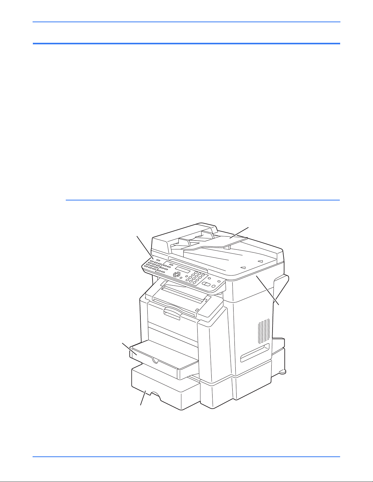
General Information
Printer Introduction and Overview
The Xerox Phaser 6115MFP Multifunction Product combines a color laser
print engine, a Copier, Scanner, and Fax. The system is a high performance,
Letter or A4, 20 page per minute (ppm) monochrome, 5 ppm Color desktop
multifunction product supporting resolutions up to 2400 x 600 dots-per-inch
(dpi). The system features USB and 10/100baseT Ethernet ports. The
Phaser 6115MFP provides a 200-sheet Tray 1 (MPT) from which specialty
media, card stock, and envelopes are fed. Tray 1 (MPT) also supports manual
feeding. An additional tray, Tray 2, provides 500 sheets of capacity. The Exit
Tray holds 100 sheets facedown.
Phaser 6115MFP options add paper capacity and functionality. For
configurations not originally equipped, a 500-Sheet Feeder (Tray 2) adds
input capacity, and the Duplex Unit enables auto-duplexed (2-sided) printing.
The Fax portion of the system incorporates a resolution of up to 203 dpi by
392 dpi. Fax features include a modem speed of up to 33.6 Kbps using V.34
standard transmission, print capability of up to a maximum of 250 printed
pages. The Fax includes a phone book, real time clock, and auto redial.
Phaser 6115MFP Front View (with Optional Sheet Feeder)
Automatic Document Feeder
Control Panel
Tray 1
Scanner
Optional Sheet Feeder
1-2 Phaser 6115MFP Multifunction Product Service Manual
s6115-419
Page 23

Phaser 6115 MFP Rear View
General Information
Duplex
Power Switch
s6115-420
Phaser 6115MFP Multifunction Product Service Manual 1-3
Page 24

General Information
System Configurations
The Phaser 6115MFP Multifunction Product is available in two configurations.
The main differences is the addition of the Duplex Unit to enable 2-sided
printing. The following table lists both configurations.
Configuration
Features
6115N 6115D
Max Print Speed (ppm) color/monochrome
Memory* 128 MB 128 MB
USB Port Yes Yes
10/100 Ethernet Port Yes Yes
Duplex Unit No Yes
PostScript and PCL Fonts Yes Yes
Print Resolutions (dpi):
Draft
Standard
Enhanced
Copy Speed (dpi or ppm):
600x300
600x600
Scan Resolutions (dpi or ppm):
600x300
600x600
500-Sheet Feeder** Optional Optional
5/20 5/20
600x600
1200x600
2400x600
Color/Mono
5/12 ppm
2.5/6 ppm
Color/Mono
70/30 mm/
sec
35/14 mm/
sec
600x600
1200x600
2400x600
Color/Mono
5/12 ppm
2.5/6 ppm
Color/Mono
70/30 mm/
sec
35/14 mm/
sec
* All configurations have two memory slots supporting 256 MB and 512 MB cards, to
a maximum of 1 GB.
**One 500-sheet feeder (Tray 2)
1-4 Phaser 6115MFP Multifunction Product Service Manual
Page 25

System Specifications
Electrical Specifications
Operating Environment
General Information
Power Requirements Voltage: AC 110 to 127 V
AC 220 to 240 V
Frequency: 50/60 Hz ± 3 Hz
Max Power Consumption 1100 W or less
Dimensions 528 (W) x 475 (D) x 531 (H) mm
20 3/4 (W) x 18 3/4 (D) x 21 (H) inch
Weight 32 kg (70 1/ 2 lb) or less
39 kg (86 lb) or less (w/packing material)
Operating Noise During standby: 39 dB (A) or less
During printing: 53 dB (A) or less
Operating Noise During standby: 35 dB (A) or less
During printing: 54 dB (A) or less
Operating Range
Temperature
Operating Range
Humidity
Operating Range
Altitude
Transportation
Range
Temperature
Transportation
Range
Humidity
10° to 32° C / 50° to 90° F (with a fluctuation of 10° C / 18° F or
less per hour)
10%-80% RH @ 15° to 32° C /59° t o 89° F t o w ith water vapor no
higher than 25.5C/77.9° F 80% condition.
0-2,500 meters (8,000 ft.)
-20° C to +55° C/-4° to 131° F
30%-85% RH, non-condensing
Phaser 6115MFP Multifunction Product Service Manual 1-5
Page 26

General Information
Product Specifications
Media Input Capacity
Type Desktop
Printing System Semiconductor laser and electrostatic image transfer to plain
Exposure System 2 laser diodes and polygon mirror
PC Drum Type OPC (organic photo conductor)
Photoconductor
Cleaning
Scan Resolution 600 x 600 dpi, 600 x 300 dpi
Print Resolution 2400 x 600 dpi, 1200 x 600 dpi, 600 x 600 dpi
Copy Resolution 600 x 600 dpi
Platen Stationary
Original Scanning Scanning in main scanning direction with a CCD
Registration Rear left edge
Paper Feeding
System
Developing
System
Charging System DC comb electrode Scorotron system
Image Transfer
System
Paper Separating
System
Fusing System Roller fusing
Paper Exit System Face down (Exit Tray capacity: 100 sheets)
paper
Blade cleaning system
Tray1: 200 sheets
Tray2: 500 sheets (Option)
Single-element developing system
Intermediate transfer belt system
Curvature separation + Charge-neutralizing system
Built-in Controllers
CPU Embedded RISC processor 48MHz
Standard memory
SDRAM
Optional Memory Not supported Interfaces Host (PC)
interface
Camera direct
interface
Network
interface
PSTN line
(Fax RX/TX)
OS compatibility Windows 98SE/Me/2000/XP/Server 2003
1-6 Phaser 6115MFP Multifunction Product Service Manual
128 MB on IPB 16 MB on LANB
USB device (High-speed mode 480 Mbps)
USB Host (Full-speed mode 12 Mbps)
Ethernet 10/100 BaseT
Telephone line jack/External device jack
Page 27

Media Specifications
Paper Type Size Paper Type Size
Letter 8.5" x 11" Government Letter 8.0" x 10.5" A4 210 x 297 mm Government Legal 8.0" x 13" Legal 8.5" x 14" SP Folio 8.5" x 12.69" Folio 210 x 330 mm DL 110 x 220 mm Executive 7.25" x 10.5" C5 162 x 229 mm B5 (JIS) 182 x 257 mm C6 114 x 162 mm B5 (ISO) 176 x 250 mm Monarch 3.88" x 7.5" A5 148 x 210 mm Com 10 4.13" x 9.5" Statement 5.5" x 8.5" Japanese PostCard 100 x 148 mm Foolscap 8" x 13" Custom size Width 92-216 mm UK Quatro 8" x 10" Length 148-356 mm* Custom Paper
Sizes
Media Types
Paper width: 92 to 216 mm (3.6" to 8.5")
Paper length: 148 to 356 mm (5.9" to 14")
2
Plain Paper (60 to 90 g/m
/ 16 to 24 lb.)
Transparencies
2
Thick stock (90 to 163 g/m
/ 25 to 40 lb.)
Postcards
Envelopes
Letterhead
2
Label stock (60-163 g/m
Glossy stock(163 g/m
/16-43 lb. bond)
2
index max/110 lb. book max)
General Information
Phaser 6115MFP Multifunction Product Service Manual 1-7
Page 28

General Information
Functional Specifications
Function Table
Function Description
Warm-up time Average: 45 seconds (100 V area)
Average: 49 seconds (200 - 240 V area)
(at ambient temperature of 23 °C/73.4 °F and rated source voltage)
Plain paper 126.78 mm/second
System Speed
First-page-out time (Plain paper)
First copy time (Plain paper)
Copy / Print speed (Plain paper)
Custom paper
sizes
Media types
Thick stock 63.39 mm/second
Transparency
42.26 mm/second
film
Full color 22 seconds or less: LetterS, A4S Monochrome 13 seconds or less: LetterS, A4S
Full color 52 seconds (600 x 300 dpi scan) Monochrome 23 seconds (600 x 300 dpi scan) Full color 5 pages/minute Monochrome 20 pages/minute
Paper width: 92 to 216 mm (3 1/2 to 8 1/2 inch)
Paper length: 148 to 356 mm (5 3/4 to 14 inch)
Plain Paper (60 to 90 g/m2 / 16 to 24 lb)
Recycled paper (60 to 90 g/m2 / 16 to 24 lb)
Transparencies
Thick stock (91 to 163 g/m2 / 25 to 40 lb)
Postcards
Envelopes
Letterhead
Label stock
Glossy stock
Plain paper and letterhead, 200 sheets
Tray capacities
Transparencies, thick stock, postcards, labels stock,
and glossy stock, 50 sheets
Envelopes, 10 sheets
Machine Durability 200,000 prints or 5 years, whichever comes first
1-8 Phaser 6115MFP Multifunction Product Service Manual
Page 29

FAX Specifications
General Information
Standard (203 dpi x 98 dpi)
Resolution
Halftone Level Standard/Fine/Super fine
Automatic
reduction
Compatibility ECM/Super G3
Modem speed V.34 (up to 33.6 Kbps)
Transmit
speed
Compression MH/MR/MMR/JBIG
Memory for
receiving
Remote setting Available via USB/Network
Paper size A4, Legal, Letter
Functions
Fine (203 dpi x 196 dpi)
Super fine (203 dpi x 392dpi)
Half tone standard/Half tone fine/Half tone super fine
Receive Supported
Transmit Not supported
3 second/page (at V.34)
4 MB for fax-RX (approx. 250 pages), (included in 32 MB NAND flash)
One touch
dial
Speed dial 100 fax numbers
Group dial 9 groups (50 destination stations for one group)
9 one-touch key on operation panel
Broadcast Available maximum 125 stations.
(One-touch dial 9 stations, speed dial 100 stations, full
dial 16 stations)
Other
supported
functions
Timer transmission, phone book, real time clock, auto
redial, reduce/split, smoothing
Phaser 6115MFP Multifunction Product Service Manual 1-9
Page 30
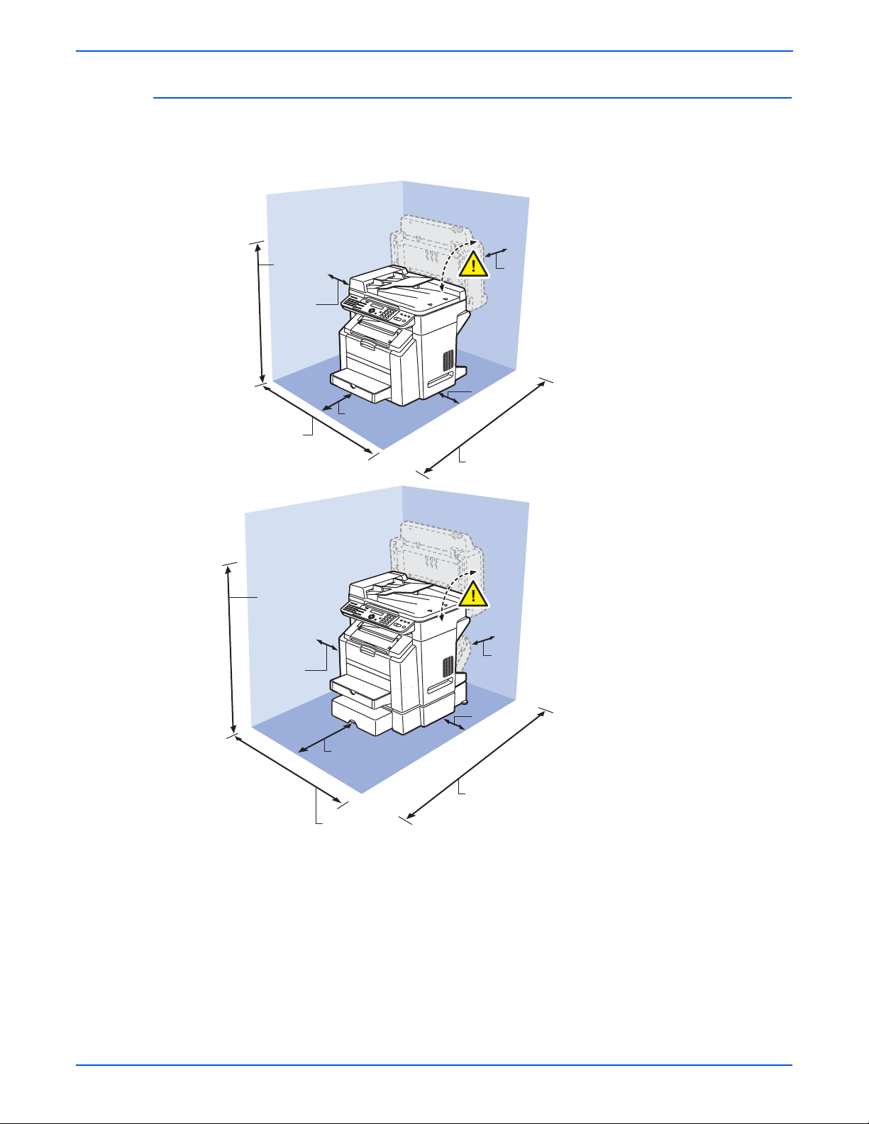
General Information
Physical Dimensions and Clearances
To ensure easy operation, consumable replacement and maintenance,
adhere to the recommended space requirements detailed below.
76.4 cm
(30.1 in.)
10 cm
(3.9 in.)
72.8 cm
(28.7 in.)
90.2 cm
(35.5 in.)
10 cm
(3.9 in.)
10 cm
(3.9 in.)
10 cm
(3.9 in.)
10 cm
(3.9 in.)
72.6 cm
(28.6 in.)
10 cm
(3.9 in.)
10 cm
(3.9 in.)
32 cm
(12.6 in.)
80 cm
(31.5 in.)
72.8 cm
(28.7 in.)
1-10 Phaser 6115MFP Multifunction Product Service Manual
s6115-459
Page 31

ADF Specifications
ADF Unit
Power requirements DC 24 V (supplied from the main unit)
Max. power consumption 30 W Dimensions 518 (W) x 350.1 (D) x 90.3 (H) mm
Weight 3.2 kg (7 lb)
Options Specifications
Duplex Unit
General Information
DC 5 V (supplied from the main unit)
1
20
/2 (W) x 13 3/4 (D) x 3 1/2 (H) inch
Power Requirements DC 24 V ± 10% (supplied fr om the main un it)
Max. Power Consumption
Dimensions 370 (W) × 153 (D) × 318 (H) mm
Weight Approx. 2.4 kg (5
500-Sheet Feeder
Power Requirements DC 24 V ± 10% (supplied from the main unit)
Max. Power
Consumption
Dimensions 495 (W) × 581 (D) × 138 (H) mm
Weight 5.0 kg
DC 5 V ± 5% (supplied from the main unit)
42 W
1
14
/2 (W) × 6 (D) × 12 3/4 (H) inch
1
/4 lb)
DC 5 V ± 5%
12 W
1
19
/2 (W) × 22 3/4 (H) × 5 1/2 (D) inch
Phaser 6115MFP Multifunction Product Service Manual 1-11
Page 32

General Information
Control Panel Description
Control Panel Buttons
The Control Panel contains one tricolor LED, a display window, and six
function buttons. These buttons navigate the menu system shown in the
display window, perform various functions, and select modes of operation for
the printer.
Auto Receive Resolution
Auto Receive Resolution
Redial/ Pause Speed Dial
Redial/ Pause Speed Dial
1 LED (Power/Status) 5 Up Arrow Button - scrolls up the menu
2 Control Panel Display 6 Down Arrow Button - scrolls down the menu
3 Cancel Button 7 OK (select) Button
4 Back Button 8 TC Change Button - rotates the toner rack to
LED Indicators:
LED State Printer State
01 02 03
01 02 03
04 05 06
04 05 06
07 08 09
07 08 09
On Hook
On Hook
1
Error Display
Error Display
QualityFunction
QualityFunction
2 in 1
Reduce/ Enlarge
2 in 1
Reduce/ Enlarge
Collate Light/ Dark
Collate Light/ Dark
4
2
Phaser 6115MFP
Phaser 6115MFP
MIX x1.00 01
A4 EMPTY
Y M C K
Y M C K
Menu
Menu
Select
Select
5 6 7
select the individual toner cartridges
8
DEF
DEF
ABC@
ABC@
1
2
3
1
2
3
GHI4JKL5MNO
GHI4JKL5MNO
6
6
PQRS7TUV8WXYZ
PQRS7TUV8WXYZ
9
0 #
0 #
9
C
C
3
CopyFax Scan
CopyFax Scan
Stop/ Reset
Start
Stop/ Reset
Start
s6115-422
Green Ready to Print
Flashing Yellow Warning (but can still print)
Flashing Green In Power Saver mode or busy (receiving or
processing data)
Flashing Red Error; cannot print
1-12 Phaser 6115MFP Multifunction Product Service Manual
Page 33

Control Panel Display
After Power-up, the following screen appears on the Control Panel:
General Information
1
6
No. Name Description
[1] Document type Displays the type of the document currently set.
[2] Zoom ratio Displays the zoom ratio currently set.
[3] Number of copies Displays the number of copies set to be made.
[4] Status Displays messages such as when paper is empty.
Displays messages such as when toner is low.
[5] Paper tray/paper size Indicates the selected paper tray and paper size.
[6] Copy density Displays the copy density currently set.
2
5
4
3
s6115-351
■ Pressing the Display key will display the [TONER REMAINING] screen.
■ Pressing the Cancel/C key will cause the Main screen to reappear.
TONER REMAINING
s6115-352
Phaser 6115MFP Multifunction Product Service Manual 1-13
Page 34

General Information
Main Engine Components
Boards and Power Supplies Locator
The following illustration provides a basic locator for the main system boards
and power supplies.
Engine Control Board
Thermistor
Image
Processor
Board
Fuser
Connectors
DC Power Supply 1
Control Panel
High Voltage
Power Supply
DC Power Supply 2
s6115-513
1-14 Phaser 6115MFP Multifunction Product Service Manual
Page 35

Motors and Fans Locator
The following illustration provides a basic locator for the main engine motors
and fans.
General Information
Scanner Cooling Fan
Fusing Motor
Scanner Motor
Power Supply Cooling Fan
Main Motor
Ventilation Fan
Developing
Motor
Rack Motor
s6115-512
Phaser 6115MFP Multifunction Product Service Manual 1-15
Page 36

General Information
Sensors and Switches Locator
The following illustration provides a basic locator for the main system sensors
and switches.
Original Cover Set Switch
Scanner Open/Close
Sensor
Output Tray Full Sensor
Cleaning Blade Sensor
Fuser Exit Sensor
Fusing Paper
Loop Sensor
Waste Toner
Near Full
Detect Board
Registration
Sensor
Transparency Sensor
IDC Sensor
Interlock
Switch
Rack
Positioning
Sensor
Temperature/
Humidity Sensor
Tray 1 Paper Empty Sensor
2nd Image Transfer Sensor
s6115-510
1-16 Phaser 6115MFP Multifunction Product Service Manual
Page 37

Solenoids and Power Switch Locator
The following illustration provides a basic locator for the main system
solenoids.
General Information
Image Transfer Solenoid
Cleaning Blade Solenoid
Power Switch
Tray 1 Paper Take-Up Solenoid
Registration Roller Solenoid
s6115-511
Phaser 6115MFP Multifunction Product Service Manual 1-17
Page 38

General Information
System Options
Phaser 6115MFP options include a 500-Sheet Feeder and a Duplex Unit.
500-Sheet Feeder (Tray 2)
The 500-Sheet Feeder (Tray 2) increases the input capacity of the system.
The feeder attaches below Tray 1 with four screws. Only one 500-Sheet
Feeder is supported. Electrical connection to the printer is made by a single
interface connector.
s6115-423
1-18 Phaser 6115MFP Multifunction Product Service Manual
Page 39

Duplex Unit
General Information
The Duplex Unit adds two-sided printing. The Duplex Unit attaches in back of
the system using two twist locks. Electrical connection to the printer is made
by an interface cable.
s6115-391
Phaser 6115MFP Multifunction Product Service Manual 1-19
Page 40

General Information
Consumables and Maintenance Parts
Consumables consist of the four toner cartridges (standard and high
capacity). Maintenance items consist of the imaging unit, the Fusing Unit, the
Transfer Roller, the Waste Box, and a maintenance kit of spare hardware.
Consumable Part Numbers
The following table lists the cartridge types and their part numbers. Refer to
Chapter 9 for a complete listing of all print engine and option parts.
Consumable Part Numbers
Description Part number
CYAN STANDARD CAPACITY PRINT CARTRIDGE,
PHASER 6120/6115mfp
MAGENTA STANDARD CAPACITY PRINT CARTRIDGE,
PHASER 6120/6115MFP
YELLOW STANDARD CAPACITY PRINT CARTRIDGE,
PHASER 6120/6115MFP
CYAN HIGH CAPACITY PRINT CARTRIDGE, PHASER 6120/
6115MFP
MAGENTA HIGH CAPACITY PRINT CARTRIDGE, PHASER
6120/6115MFP
YELLOW HIGH CAPACITY PRINT CARTRIDGE, PHASER
6120/6115MFP
BLACK HIGH CAPACITY PRINT CARTRIDGE, PHASER
6120/6115MFP
Maintenance Part Numbers
The following table lists the cartridge types and their part numbers. Refer to
Chapter 9 for a complete listing of all print engine and option parts.
Maintenance Part Numbers
113R00689
113R00691
113R00690
113R00693
113R00695
113R00694
113R00692
Description Part number
FUSING UNIT, 110V, PHASER 6120/6115mfp 126K23192
FUSING UNIT, 220V, PHASER 6120/6115MFP 126K23202
IMAGING UNIT, PHASER 6120/6115MFP 108R00691
TRANSFER ROLLER, PHASER 6120/6115MFP 059E05450
HARDWARE MAINTENANCE KIT, PHASER 6120/6115MFP 604K35500
1-20 Phaser 6115MFP Multifunction Product Service Manual
Page 41

Consumable Life Counter Behavior
Internal counters track Consumables and Maintenance Items life usage. The
Image Processor Board monitors these counters in order to display the near
end-of-life and end-of-use messages.
Life ratings are based on A-size sheets at 5% coverage. Imaging Unit life
ratings are based on average 4 page job length.
Toner Cartridges Print Life
General Information
Black-Capacity
Color Capacity Standard/Hi
Maintenance Items
Imaging Unit 35,000
Fusing Unit 100,000
Transfer Roller and Waste Box 25,000
Feed Roller Kit up to 100,000
Low/Out Behavior for Consumables
Front Panel
Message Low Hard Stop Reset to 0
Toner (pixel) Low / Out 96%/
88%*
Toner (page) Low / Out 6000 pages By new toner
Imaging unit
(rotation)
Transfer belt No No No By front panel
Fusing Unit No No No By control panel
Transfer roller No No No By front panel
Pick roller No No No none
* For 4.5K/1.5K toner. Toner life calculations are based on 5% coverage.
** 45,000 images for continuous printing, shorter job length will shorten the
imaging unit life.
Low / Out 96% when waste toner box full By new imaging
4500
1500, 4500
By new toner
unit
(user)
(Service)
(Service)
Phaser 6115MFP Multifunction Product Service Manual 1-21
Page 42

Theory of Operation
In this chapter...
■ Operational Overview of the Phaser 6115MFP
■ Paper Path of the Printer
■ Major Assemblies and Functions
■ Sensors
Chapter
2
Page 43

Theory of Operation
Operational Overview of the Phaser 6115MFP
The Phaser 6115MFP Multifunction Product is a full-color laser printer that
utilizes electrophotographic recording principals to place a full color image
onto the print media. The system, as it appears in the following illustration,
contains a drum and developing unit for each color [yellow, magenta, cyan
and black (YMCK)], and places the toner image of each color onto print media
producing full-color prints.
Print Cycle
The block diagram of the Phaser 6115MFP print cycle provides the sequence
of events for the xerographic process and the paper flow into and out of the
printer.
Paper Separation
2nd Image Transfer
Transfer Belt
Cleaning
1st Image Transfer
Photo
Developing
Printer Image
Processing
The Phaser 6115MFP print process consists of these steps:
1. Exposure
The surface of the Drum is irradiated with the laser light and an
electrostatic latent image is formed.
2. Developing
The toner, negatively charged in the Hopper, is attracted onto the
electrostatic latent image formed on the surface of the Drum.
Conductor
Laser Exposure
PC Drum Cleaning
Photo Conductor Charging
s6115-396
2-2 Phaser 6115MFP Multifunction Product Service Manual
Page 44

Theory of Operation
A DC negative bias voltage is applied to the Developing Roller, thereby
preventing toner from sticking to the background image portion.
Developing Roller
Photo Conductor
s6115-081
3. Image Transfer to Belt
A DC positive voltage is applied to the backside of the Transfer Belt to
attract the visible, developed image from the surface of the Drum.
4. Image Transfer to Media
A DC positive voltage is applied to the backside of the paper to attract the
visible, developed image on the surface of the Transfer Belt to the media.
5. Paper Separation
A Charge Neutralizing Cloth is provided on the guide plate to neutralize
the charge.
Charge Neutralizing Cloth
Charge Neutralizing Cloth
Transfer Belt
2nd Transfer Roller
6. Transfer Roller Cleaning
The residual toner left on the surface of the Transfer Roller) is removed by
an alternating DC charge that transfers the waste toner back to the
Transfer Belt for collection by the Transfer Belt cleaning blade.
2nd Transfer Roller
s6115-096
Transfer Belt
s6115-095
Phaser 6115MFP Multifunction Product Service Manual 2-3
Page 45

Theory of Operation
System Control
7. Transfer Belt Cleaning
A charge is applied to the Transfer Belt. By potential difference, residual
toner on the surface of the Transfer Belt is collected for cleaning. The
toner scraped off the surface of the photo conductor is collected in the
Imaging Unit.
8. Fusing
Toner is permanently fused to the paper by the combination of heat and
pressure applied by the Fuser.
The following diagram shows the major operating components and their basic
connection to each other.
CCD Unit
Scanner Motor
Various Scanner Sensors
DC Power Supply 2
Scanner Cooling
Fan Motor
Scanner Unit
Open/Close Sensor
DC Power Supply 1
Lower Feeder Unit
Duplex Unit
Paper Pick-up/
Transport
Scanner
Control Panel
Image Processing Board
Image Processing
Laser unit
Engine Control Board
CPU
Auto Document
Feeder
Control System Line
Image Bus Line
Image Process
Fusing
Power Supply/
High Voltage
s6115-068
2-4 Phaser 6115MFP Multifunction Product Service Manual
Page 46

Paper Path of the Printer
s6115-0
Main Print Engine Paper Path
Theory of Operation
The print media is supplied from Tray 1 or the optional Tray 2, and is
transported into the printer along the paper path as shown in the diagram.
Output Tray
Tray 1 (MPT)
Tray 2 (Optional
500-Sheet Feeder)
Automatic Document Feeder (ADF) Print Path
s6115-045
ADF Tray
47
Phaser 6115MFP Multifunction Product Service Manual 2-5
Page 47

Theory of Operation
Major Assemblies and Functions
The location of the system’s primary functional components is shown.
11
10
9
8
7
6
5
1 Fusing Unit 7 Toner Cartridges
2 Duplex Unit 8 Imaging Unit
1
s6115-044
2
3
4
3 Transfer Roller 9 Transfer Belt
4 Tray 2 Feeder 10 Scanner
5 Tray 1 Feeder 11 Auto Document Feeder (ADF)
6 Laser
2-6 Phaser 6115MFP Multifunction Product Service Manual
Page 48

Fusing Unit
Theory of Operation
Functional components of the Fusing Unit appear below.
Thermistor
Cleaning Roller
Heater Lamp
Fuser Speed Regulation
Thermostat
Heating Roller
Exit Sensor
Pressure Roller
s6115-057
The Fuser is driven by the Fusing Motor and employs both speed and
temperature regulation to maintain the proper fusing properties. The fusing
speed is changed in three steps depending on the media type.
Fusing Speeds
Media Type
Fusing
Speed
(mm/sec)
Fusing
Speed
(PPM)
Plain paper, letterhead 126.78 13
Thick stock, postcards, labels, glossy stock 63.39 6
Transparency film, envelopes 42.26 4
To prevent double transferred image or brush effect, the difference between
the fusing speed and paper transport speed during image transfer is
corrected. The fusing speed is changed in two steps relative to the system
speed, either at high speed (which is +2% of the system speed) or low speed
(which is -2.5% of the system speed).
Phaser 6115MFP Multifunction Product Service Manual 2-7
Page 49

Theory of Operation
Fusing Motor speed is regulated using the Fusing Loop Sensor output
following this process:
1. The initial fusing speed is set to the low speed. This causes the Transfer
Roller of the paper transport system to feed paper at a faster rate than the
speed of the fuser. This action causes a loop, or a bending effect of the
paper (see illustration below).
2. When the length of the loop formed in the paper becomes greater, the
Fusing Loop Sensor is activated (blocked).
3. While the Fusing Paper Loop Sensor remains activated, the fusing speed
increases to the high level.
4. When the Fusing Paper Loop Sensor is deactivated, the fusing speed
immediately switches to the low level.
5. The sequence of these operations is repeated so that the fusing speed is
changed automatically according to the loop length. This effectively
compensates for the difference between the fusing speed and paper
transport speed during image transfer.
s6115-073
s6115-072
2-8 Phaser 6115MFP Multifunction Product Service Manual
Page 50

Fuser Temperature Regulation
A thermistor detects the surface temperature of the Fusing Unit’s heat roller.
The heater lamp is turned On and Off as necessary to achieve the set
temperature.
The following chart illustrates fusing temperature regulation during
monochrome printing on plain paper.
Theory of Operation
Power Switch ON
Copy/Print Start
Fusing Ready Temperature
[3]
(°C)
185
180
174
169
167
100
[1]
[2]
[*a]
[*b]
60
Approx. 45 sec.
■ Warm-up (1), heat the roller to 178 C set temperature. Warm-up requires
[4]
s6115-069
approximately 45 seconds (120 V) or 49 seconds (240 V).
■ Standby state (2), maintain the roller temperature at 180 C. If the roller
temperature is 60 C or less when the warm-up cycle starts, the set
temperature changes to 185 C. (5 min.) After 5 min., the set temperature
returns to 180 C.
■ Print cycle (3), the set temperature is 189 C. If the Temperature/Humidity
Sensor indicates a temperature of less than 60 C, the set temperature is
increased to 184 C.
■ Standby state (4), maintain the roller temperature at 180 C.
Phaser 6115MFP Multifunction Product Service Manual 2-9
Page 51

Theory of Operation
The following chart illustrates fusing temperature regulation during color
printing on plain paper.
Power Switch ON
Copy/Print Start
Fusing Ready Temperature
[4]
184
(°C)
189
185
180
167
100
[3]
[*a]
[2]
[*b]
[1]
60
Approx. 45 sec.
s6115-070
■ Warm-up (1), heat the roller to 178 C set temperature. Warm-up requires
approximately 45 seconds (120 V) or 49 seconds (240 V).
■ Standby state (2), maintain the roller temperature at 180 C. If the roller
temperature is 60 C or less when the warm-up cycle starts, the set
temperature changes to 185 C. (5 min.) After 5 min., the set temperature
returns to 180 C.
■ Print cycle (3), the set temperature is 169 C. If the Temperature/Humidity
Sensor indicates a temperature of less than 20 C, the set temperature is
increased to 174 C.
■ Standby state (4), maintain the roller temperature at 180 C.
Warm-up regulation is performed when the Power Switch is turned On, a
malfunction or paper misfeed is reset, the Energy Saver mode is canceled, or
the door is opened and closed.
After 20 minutes of inactivity, the standby state set temperature changes to
170 C if interior temperature is less than 20 C or 165 C if the interior
temperature is 20 C or higher.
2-10 Phaser 6115MFP Multifunction Product Service Manual
Page 52

Fusing Temperatures by Media
Not
During printing, the roller set temperature varies according to the media as
listed in the following tables:
Fusing Temperatures for Monochrome
Theory of Operation
Media Type Typical (°C)
Temperature/humidity
Sensor more than 20 °C
Plain paper, letterhead 169 174
Plain paper , lette rhead 257 mm
169 174
or less
Thick stock, postcards, labels 169
Transparencies 169
Envelopes 194*
Glossy stock 169
* The temperature is controlled at 159 C if the system’s interior temperature is 20 ×C or
more and relative humidity is 40% or higher.
e
There is a Control Panel command which obtains environmental
temperature and humidity levels. However, this command is for internal
use only and not available from the service menus.
If the print cycle is started while the Temperature/Humidity Sensor indicates
an internal temperature of 20 C or more, control is returned back to one
having a control temperature of more than 60 ×C after five printed pages have
been produced.
Fusing Temperatures for Color (1-sided)
Temperature/
Media Type
Plain paper,
letterhead
Plain paper,
letterhead 257
mm or less
Thick stock,
Roller temp at
warm-up start
Typical (°C)
60 C or less 189 194 189
More than 60 C 184 194 184
60 C or less 189 194 189
More than 60 C 184 194 184
_ 184
humidity
Sensor less
than 20 °C
postcards,
labels
Transparencies _ 179
Envelopes _ 194*
Glossy stock _ 190 190 185
Temperature/
humidity Sensor
more than 20 °C
Phaser 6115MFP Multifunction Product Service Manual 2-11
Page 53

Theory of Operation
Not
* The temperature is controlled at 159 ×C if the system’s interior temperature is 20 ×C or
more and relative humidity is 40% or higher.
e
Fuser thermal regulation stops and the Fuser heat lamp turned Off when
the system enters Energy Saver mode, a door is opened, or an error
occurs.
Fuser Overheat Protection
The machine provides protection at three different stages to prevent
abnormally high temperature of the Fusing Unit.
■ Soft Protection. If the Thermistor detects a temperature exceeding a
predetermined value, the error code representing abnormally high
temperature is displayed. At this time, the heater lamp is turned Off, and
new print cycles are prohibited.
■ Hard Protection. If the CPU overruns and the output level of the CPU of
the Mechanical Control Board becomes a HIGH or LOW level, and not a
pulse output, and a predetermined temperature or higher is detected, a
circuit within the Mechanical Control Board turns OFF the relay to shut
down the power supply to the Heater Lamp.
■ Thermostat Protection. If neither the soft protection nor hard protection
detect an abnormally high temperature due to a defective Thermistor or
other reason, the Thermostat operates at the specified temperature. This
shuts down the power supply to the Heater Lamp, thus forcibly turning it
OFF.
5V
Engine Control Board
CPU
Heater Lamp
A/D
Thermistor
Thermostat
Heating Roller
GND
Hard
Protection
Fusing Pressure Roller
Circuit
Laser Safety Switch
Watchdog
Circuit
Fuser Wdt
Reset
Triac Circuit
Heater
Remote
Power Switch
ON/OFF
s6115-101
2-12 Phaser 6115MFP Multifunction Product Service Manual
Page 54

Theory of Operation
Not
Print Speed Thermal Control
Print speed thermal control prevents the temperature on edges of the heat
roller from increasing during a multi-print cycle using smaller size media. The
process timing between sheets increases according to the number of printed
pages per job and the paper length. The following tables provide page per
minute (ppm) output by media size during print speed thermal control
conditions. Output speeds are also affected by environmental conditions.
Monochrome Prints in Typical Environmental Conditions
In millimeters(mm)
Media Length
Width Less than 210 210 ~ 215 216 ~ 256 257 ~ 296
139 mm or less 14 ppm 14 ppm 14 ppm 14 ppm
140 - 148 mm 18 ppm 18 ppm 14 ppm 14 ppm
149 - 182 mm 19 ppm 18 ppm 14 ppm 14 ppm
183 ~ 210 mm 20 ppm 20 ppm 20 ppm 14 ppm
The low temperature environment refers to the condition, in which the
Temperature/Humidi ty Sen so r detects a temperatu re of less than 20 C.
e
There is a Control Panel command which obtains environmental
temperature and humidity levels. However, this command is for internal
use only and not available from the service menus.
Monochrome Prints in Low Temperature Environmental Conditions
In millimeters(mm)
Media Length
Width 210 211 ~ 216 217 ~ 257 258~ 297
139 mm or less 12 ppm 12 ppm 12 ppm 12 ppm
140 - 148 mm 15 ppm 15 ppm 12 ppm 12 ppm
149 - 182 mm 16 ppm 15 ppm 12 ppm 12 ppm
183 ~ 210 mm 17 ppm 17 ppm 17 ppm 12 ppm
For Color printing, these output speeds apply:
Color Prints in Typical Environmental Conditions
In millimeters(mm)
Media Length
Width 210 211 ~ 216 217 ~ 257 258~ 297
139 mm or less 3 ppm 3 ppm 3 ppm 3 ppm
140 - 148 mm 5 ppm 5 ppm 3 ppm 3 ppm
149 - 182 mm 5 ppm 5 ppm 3 ppm 3 ppm
183 ~ 210 mm 5 ppm 5 ppm 5 ppm 3 ppm
Phaser 6115MFP Multifunction Product Service Manual 2-13
Page 55

Theory of Operation
Scanner
Scanner components include:
■ Scanner Latch
■ Scanner Motor and Drive Belt
■ Scanner Fan
■ Platen Glass
■ Scanhead
Functional components of the Scanner are illustrated below.
s6115-067
The Scanner does not include sensors for determining the size of the original
document. Original media size settings are made on the Control Panel. An
error occurs following the print cycle if the correct media size is not selected
on the Control Panel or loaded in the tray.
2-14 Phaser 6115MFP Multifunction Product Service Manual
Page 56

Scanner Latch
The Scanner Latch works with the ADF Lever to prevent the simultaneous
opening of both assemblies. When the Scanner is opened, the ADF is locked
closed. Likewise, when the ADF is opened, the Scanner is locked closed.
Pulling the Scanner Latch Lever disengages the Scanner Lock Pawl, allowing
the Scanner to be opened.
If the ADF is open, the ADF Lever locks the Scanner Latch mechanism to
prevent the Scanner from opening.
Theory of Operation
s6115-059
Laser Assembly
s6115-058
The Laser Assembly in the Phaser 6115MFP printer has two laser diodes.
The laser diode control circuitry adjusts the light intensity for each beam
automatically. Image data is transmitted to the laser diodes in the Laser
Assembly as digital signals. The laser diodes convert the image data from
digital signals to optical signals. The Laser Assembly monitors and adjusts the
intensity of the laser beams to attain a stable electrostatic image. The Laser
Assembly is replaced as a complete assembly. Functional components within
the Laser appear below.
Phaser 6115MFP Multifunction Product Service Manual 2-15
Page 57

Theory of Operation
Semiconductor Laser Assembly
G2 Lens
SOS Board
Mirror
G1 Lens
Prism
Imaging Unit Exposure
The surface of the Imaging Unit is irradiated with a laser light and an
electrostatic latent image is formed. The polygon mirror has four faces. The
two-beam laser array consists of two laser diodes arranged vertically. Two
lines are scanned through a single face of the polygon mirror.
Beam A
Beam B
Direction of Rotation
of Photo Conductor
Laser Diode
Polygon Mirror Assembly
Beam A
Beam B
Photo
Conductor
G2 Lens
G1 Lens
s6115-048
Photo Conductor Surface
scan motion.
Two lines are
scanned in a single
Polygon Mirror
Return Mirror
Direction of Rotation
s6115-076
2-16 Phaser 6115MFP Multifunction Product Service Manual
of Photo Conductor
Page 58

Laser Write Process
1. The laser light strikes the polygon mirror.
2. The four-sided polygon mirror rotates at high speeds driven by the
polygon motor.
3. The Start-of-Scan (SOS) Sensor monitors laser light emission and
initiates timing for each line of the scanning process.
Theory of Operation
Photo Conductor
Semiconductor Laser
SOS Board
Polygon Motor
s6115-077
Laser Write Timing
When a Ready signal is detected after the print cycle begins, a Laser On
signal is output from the Engine Control Board. The Laser On signal triggers
each laser diode illuminating the SOS Board and generating an SOS signal.
The SOS signal is used to synchronize the timing at which the laser write
each scan line.
The print start position in the CD direction is determined by the CD Print Start
signal (/HSYNC) that is output from the Image Processor Board and the width
of the paper.
The print start position in the FD direction is determined by the Image Write
Start signal (TOD) that is output from the Image Processor Board and the
length of the paper. The laser emission area is determined by the paper size.
Phaser 6115MFP Multifunction Product Service Manual 2-17
Page 59

Theory of Operation
/
The area of 4 mm on both the leading and trailing edges of the paper is,
however, the void image area.
HSYNC
/VIDEO
/VIDEO /TOD
s6115-041
2-18 Phaser 6115MFP Multifunction Product Service Manual
Page 60

Imaging Unit
Theory of Operation
The Imaging Unit contains the photo-conductive drum, a cleaning blade, and
a waste toner reservoir. The Drum is driven by the Main Motor through a
series of gears. When the Main Motor is energized, it turns the drive gear,
which in turn rotates the drum.
Main Motor
Photo Conductor
s6115-071
The cleaning blade is pressed against the drum to remove excess toner.
Waste toner is stored in the Imaging Unit.
Phaser 6115MFP Multifunction Product Service Manual 2-19
Page 61

Theory of Operation
Waste toner levels are monitored by the Waste Toner Sensor.
Cleaning Blade
s6115-078
An electrical charge is applied to the drum by an electrode mounted near the
drum. This charge attracts toner from the Toner Cartridge developer roller.
The image stabilization control process controls the grid voltage (Vg) applied
to the electrode’s grid mesh.
Grid Mesh
s6115-049
2-20 Phaser 6115MFP Multifunction Product Service Manual
Page 62

Imaging Unit Life
Toner Cartridge
Theory of Operation
A counter tracks the number of prints since the last detection of a new
Imaging Unit. As this count nears its maximum value, the system generates a
warning message. When the count reaches the maximum value, a
replacement error is generated. The counter is reset following the detection of
a new Imaging Unit.
The system checks for a new Imaging Unit when the Power Switch is turned
On or the front door is closed. If a new Imaging Unit is detected, the image
stabilization sequence is carried out.
The life counter is reset when a new DC is detected. When a predetermined
number of printed pages are produced after the life value has been reached,
the machine displays a DC replacement message.
The system employs four Toner Cartridges (CMYK) installed in a revolving
Toner Cartridge Rack that positions each cartridge’s developer roller over the
Drum. A cross section of the Toner Cartridge showing functional components
appears below.
Hopper
Supply Roller
Developing Roller
2nd Regulator
Blade
Agitating Blade
1. Toner stored in the hopper is agitated by the agitating blade and
conveyed into the toner supply portion by the conveyance blade fitted to
the leading edge of the agitating blade.
2. Toner in the toner supply portion is conveyed by the supply roller onto the
developing roller.
3. At this time, the 1st and 2nd regulator blades moderate the height of toner
on the surface of the developer roller.
4. When positioned by the Toner Cartridge Rack in the developing position,
toner adheres to the latent image on the drum. T oner left on the surface of
the developer roller following transfer to the drum is returned to the toner
supply portion.
1st Regulator Blade
s6115-079
To attract toner to the drum, a developing bias voltage (Vb) that includes
both DC (-) and + AC components is applied to the developing roller
during development. The AC component is applied only during
Phaser 6115MFP Multifunction Product Service Manual 2-21
Page 63

Theory of Operation
development. The developing bias voltage (Vb) supplied by the High
Voltage Power Supply is applied to the developing roller at the contact
point shown below.
Developing Bias Contact Point
Seal Bias Contact Point
Developer Roller Drive
The Developer Roller is driven by the Developing Motor and intermediate
gears.
Photoconductor
Regulator Blade Contact Points
Developer Roller
s6115-080
Main Motor
Developing
Motor
s6115-050
2-22 Phaser 6115MFP Multifunction Product Service Manual
Page 64

Theory of Operation
When the Toner Cartridge Rack is stationery at the developing position, the
Developer Roller drive gear meshes with int er med iat e gear s allowi ng the
Development Motor to engage the roller.
Intermediate Gear
s6115-051
Phaser 6115MFP Multifunction Product Service Manual 2-23
Page 65

Theory of Operation
Toner Cartridge Rack
The Toner Cartridge Rack holds the four Toner Cartridges and rotates to
position each cartridges’ Developer Roller in the developing position. The
rack is driven by the Rack Motor.
s6115-065
The Toner Cartridge Rack has three stop positions: the standby (reference)
position, the developing position, and the cartridge replacement position:
■ The standby position is the Toner Cartridge Rack position when the
system completes a warm-up cycle or waits for a print command.
■ The development position is when the Toner Cartridge Rack stops during
development of a specific color of toner.
■ The cartridge replacement position refers to the position at which the
Toner Cartridge Rack is stopped for replacement of the Toner Cartridge of
a specific color of toner.
2-24 Phaser 6115MFP Multifunction Product Service Manual
Page 66

Theory of Operation
The standby position is 45 degrees before the developing position of the
Black (K) Toner Cartridge.
C
K
M
Y
Standby Position
The developing position is where the Toner Cartridge Rack is rotated 45
degrees from the standby position.
C
M
The cartridge replacement position is where the Toner Cartridge Rack is
rotated 70 degrees from the developing position.
K
Y
45°
45°
s6115-082
Photo Conductor
C
M
Developing Position
K
Y
s6115-083
0°
For Developing of K
70°
C
M
K Developing Position
Phaser 6115MFP Multifunction Product Service Manual 2-25
K
Y
Cartridge Replacement Position
K
Y
C
M
s6115-084
Page 67

Theory of Operation
Operation for Monochrome
The Toner Cartridge Rack follows these steps for monochrome prints.
1. The Toner Cartridge Rack is stationary at the standby position.
2. When a print request is received from the controller, the Toner Cartridge
Rack is rotated to bring the K Toner Cartridge to its developing position.
3. Development of monochrome printing is started.
4. When the development is completed, the Toner Cartridge Rack is rotated
and brought to a stop at the standby position.
Step 1 Step 2 Step 3
C
M
Y
Standby
Position
Operation for Color
The Toner Cartridge Rack follows these steps for color prints.
1. The Toner Cartridge Rack is stationary at the standby position.
2. When a print request is received, the Toner Cartridge Rack rotates to
place the Y Toner Cartridge to its developing position.
3. Development of Y is carried out.
4. When development of Y is completed, the Toner Cartridge Rack is rotated
to bring the M Toner Cartridge to its developing position.
5. Development of M is carried out.
6. Similarly, the Toner Cartridge Rack rotates and development of C is
carried out, followed by K.
7. When the development of K is completed, the Toner Cartridge Rack
rotates to the standby position.
Step 1 Step 2 Step 3
Step 4
C C
K K
K
Y
M
Rack is Rotated
M
Y
Monochrome
Printing
C
M
Y
Standby
Position
K
s6115-085
Step 4
C
K
M
Y
Standby
Position
Step 5
Y
M
K
C
M Development
K K
Y Y
C MC
M
Step 6
M C
C K
K
Y YM
Rack is Rotated
+
C Development
Y Development
Step 7
Rack is Rotated
+
K Development
Rack is RotatedRack is Rotated
Y
Step 8
C
M
Y
Standby
Position
M
CK
K
s6115-086
2-26 Phaser 6115MFP Multifunction Product Service Manual
Page 68

Position Detection
The Toner Cartridge Rack stop position for each color of toner is detected by
the Rack Positioning Sensor. Openings around the circumference of the
Toner Cartridge Rack actuate the Rack Position Sensor at each stop position.
Theory of Operation
Slits
Rack Positioning Sensor
s6115-087
When the Toner Cartridge Rack rotates past the slit for the K developing
position, the Rack Positioning Sensor is actuated. This indicates that the
current development is for K. Through pulse control of the Rack Motor, the
Rack Motor drives the Toner Cartridge Rack to the standby position.
Direction of Rotation of
the Toner Cartridge Rack
Rack Positioning
Sensor
C
M
K
Y
Toner
Cartridge
Rack
Standby
Position
Standby Position Detecting Position
YMCK
Detection of C
Developing
Position
Detection of M
Developing
Position
Detection of Y
Developing
Position
Detection of K
Developing
Position
s6115-088
When a replacement request is made for a Toner Cartridge, the Toner
Cartridge Rack is rotated 70 degrees from the depleted cartridges’ developing
position through pulse control of the Rack Motor.
Phaser 6115MFP Multifunction Product Service Manual 2-27
Page 69

Theory of Operation
Transfer Belt
The Transfer Belt serves to accumulate the images produced by the four
developer rollers before transferring the composite image to the media with
the Transfer Roller. Components of the Transfer Belt appear below.
Driven Roller
Transport Belt
1st Transfer Roller
IDC Sensor
Transfer Belt
Drive Roller
Cleaning Blade
Toner
Collecting Auger
Photoconductor
Belt Positioning Sensor
s6115-052
In addition to the Transfer Belt, a Transfer Roller (sometimes referred to as
the 2nd Transfer Roller) transfers the composite image to the media for
fusing.
2nd Transfer Roller
Pressure
Slider
Pressure/Retraction Roller
s6115-053
2-28 Phaser 6115MFP Multifunction Product Service Manual
Page 70

Transfer Drive
The Transfer Belt and Transfer Roller (sometimes referred to as the 2nd
Transfer Roller) are driven by the Main Motor. The Transfer Roller Clutch at
one end of the (2nd) Transfer Roller engages the Main Motor drive.
Theory of Operation
Main Motor
Transfer Roller Clutch
2nd Transfer Roller
Transfer Belt
Drive Roller
1st Transfer Roller
Transfer Belt Unit
s6115-054
Phaser 6115MFP Multifunction Product Service Manual 2-29
Page 71

Theory of Operation
Transfer Belt Cleaning
The Transfer Belt Cleaning Blade collects residual toner off the surface of the
Transfer Belt, and a toner collecting auger transfers waste toner to the
Imaging Unit reservoir.
During color printing, an image is formed on the Transfer Belt for each color.
The Cleaning Blade uses a retraction mechanism to lift off the belt during the
printing process. During monochrome printing, no retraction sequence is
needed. The Cleaning Blade is normally in contact with the Transfer Belt.
Driven Roller
Cleaning Blade
Toner Collecting Screw
s6115-089
Cleaning Blade retraction operations are driven by the Main Motor, Cleaning
Blade Solenoid, pressure cam, lever, and Cleaning Blade Position Sensor.
2-30 Phaser 6115MFP Multifunction Product Service Manual
Page 72

Theory of Operation
When the Cleaning Blade Solenoid is energized, drive from the Main Motor is
transmitted to the pressure cam.
Cleaning Blade Solenoid
Lever
Pressure Cam
Main Motor
Cleaning Blade
Sensor
Belt Cleaner Assy
s6115-090
The sequence of events to retract the Cleaning Blade are:
1. Drive from the Main Motor is transmitted to the drive gear.
2. Rotation of the drive gear is transmitted to the pressure cam.
3. When the Cleaning Blade Solenoid is energized, the half-moon-shaped
pressure cam rotates a half turn to push the lever forward to retract the
Cleaning Blade.
Phaser 6115MFP Multifunction Product Service Manual 2-31
Page 73

Theory of Operation
4. The Cleaning Blade Position Sensor signal indicates whether or not the
Cleaning Blade is retracted from the Transfer Belt.
Lever
Pressure Cam
s6115-091
The position of the Cleaning Blade is unknown when the Power Switch is
turned On or the cover is opened and closed. To determine home position for
the Cleaning Blade, the system performs a home position detection sequence
during a warm-up cycle. The Cleaning Blade Solenoid is energized to start a
retraction sequence. When the Cleaning Blade Position Sensor is blocked,
indicating home position, the Cleaning Blade Solenoid is de energized.
Transfer Belt Position Sensor
Image development requires the creation of a composite image on the
surface of the Transfer Belt. The leading edge of each color component of the
image must register correctly on the Transfer Belt’s surface. The position of
the Transfer Belt is monitored by the Transfer Belt Position Sensor. The
optical sensor detects holes in the Transfer Belt.
Two detection holes are punched in the Transfer Belt. The image write start
position varies according to the media size. For A4 or smaller media, the
image write start position, as determined by the sensor, is detection hole A.
2-32 Phaser 6115MFP Multifunction Product Service Manual
Page 74

Theory of Operation
For a media sizes larger than A4, detection hole B is the reference for the
image write start position.
Direction of Rotation of Transfer Belt
Transfer Roller
Detection
Hole B
Belt Positioning Sensor
Detection
Hole A
s6115-104
The Transfer Roller (sometimes referred to as the 2nd Transfer Roller)
transfers the developed image from the Transfer Belt to the media. To allow
development of the composite color image on the Transfer Belt, the Transfer
Roller retracts from the belt while the image is developed.
The Transfer Roller retraction operation is performed by the Main Motor,
Image Transfer Solenoid, and Transfer Roller Clutch. When the Image
Transfer Solenoid is energized, drive from the Main Motor is transmitted to the
Transfer Roller Clutch.
Main Motor
Transfer Belt
2nd Transfer Assy
Pressure/Retraction
Clutch
2nd Transfer Roller
Pressure/Retraction Clutch
2nd Image Transfer Solenoid
s6115-092
Phaser 6115MFP Multifunction Product Service Manual 2-33
Page 75

Theory of Operation
Image Transfer
To apply pressure to the Transfer Roller (sometimes referred to as the 2nd
Transfer Roller), the system follows these steps:
1. Drive from the Main Motor is transmitted to the drive gear.
2. Rotation of the drive gear is transmitted to the Transfer Roller Clutch.
3. When the 2nd Image Transfer Solenoid is energized, the Transfer Roller
Clutch rotates a half turn. This moves the Pressure Slider.
4. When the Pressure Slider is moved, the ribs push against the Pressure
Retraction Roller.
5. When the assembly is pushed up, the Transfer Roller presses against the
Transfer Belt.
Pressure/Retraction Roller
2nd Image Transfer
Transfer Roller Retraction
To retract the Transfer Roller from the Transfer Belt, the system performs the
following steps:
1. When the Image Transfer Solenoid is energized, the Transfer Roller is
presses against the Transfer Belt and the Transfer Roller Clutch rotates a
half turn. This moves the Pressure Slider.
2. When the Pressure Slider moves, the Transfer Assembly, which has been
pushed up by the ribs on the Pressure Slider, lowers.
2nd Transfer Assy
2nd Image Transfer Solenoid
Pressure Slider
Pressure/Retraction
Clutch
Ribs
s6115-093
2-34 Phaser 6115MFP Multifunction Product Service Manual
Page 76

Theory of Operation
3. When the Transfer Assembly lowers, the Transfer Roller retracts from the
Transfer Belt.
Pressure/Retraction Roller
2nd Image Transfer
Transfer Roller Cleaning
DC positive and negative transfer bias voltages are alternately applied to the
Transfer Roller. These charges oppose those on the Transfer Belt attracting
toner residue on the Transfer Roller back to the Transfer Belt. The Transfer
Belt cleaning blade collects the waste toner from the belt and stores the waste
in the Imaging Unit.
Transfer Roller cleaning occurs when:
2nd Transfer Assy
2nd Image Transfer Solenoid
Pressure Slider
Pressure/Retraction
Clutch
Ribs
s6115-094
Process Control
■ Power Switch is turned ON
■ Cover is opened and closed
■ A media error occurs during a print cycle.
■ A paper em pty condition occurs during a print cycle.
■ A paper size error occurs during a print cycle.
For stable printing, the parameters related to forming both the electrostatic
and toner image are continuously monitored and adjusted by the printer.
Parameter correction and control over the entire printing process is called
“process control”. Two primary process control mechanisms are used by the
system, Automatic Transfer Voltage Control (ATVC) and Automatic Image
Density Control (AIDC).
Phaser 6115MFP Multifunction Product Service Manual 2-35
Page 77

Theory of Operation
Automatic Transfer Voltage Control (ATVC)
ATVC optimizes the transfer output. A constant current flows through each of
the Transfer Rollers. The resistance of each of the 1st Transfer Roller, the
Transfer Roller (sometimes referred to as the 2nd Transfer Roller), and
Transfer Belt is measured. A TVC automatically adjusts the appropriate image
transfer output voltage (bias) to be applied to each Transfer Roller and
transfer belt during the print cycle.
Apply the constant current to
the 1st Transfer Roller
Measure the resistance of
the 1st Transfer Roller
Establish the 1st Transfer
output voltage
Constant
Current
Constant
Voltage
Measure
Resistance
HVPS
Constant
Current
Apply the constant current to
the 2nd Transfer Roller
Measure the resistance of
the 2nd Transfer Roller
Establish the 2nd Transfer
output voltage
Automatic Image Density Control (AIDC)
AIDC stabilizes image density to provide accurate tone reproduction. AIDC
uses the IDC Sensor and Temperature/Humidity Sensor to monitor system
and environmental parameters to regulate the following:
■ Leak detection control
For the clearance between the Drum and Developing Roller, an optimum
developing bias voltage is established that prevents leak image or uneven
density.
2nd Transfer Roller
Transfer Belt
Transfer Belt
Drive Roller
1st Transfer Roller
Transfer Belt
Photo Conductor
Ground
s6115-397
■ IDC Sensor intensity control
Adjustments are made to correct changes in IDC Sensor characteristics
due to changes over time or contamination. The IDC Sensor is a photoreflective sensor that emits light from an LED and detects the reflected
light returning from the Transfer Belt. The light emitted from the LED is
controlled so that the reflected light density is constant.
2-36 Phaser 6115MFP Multifunction Product Service Manual
Page 78

Theory of Operation
■ Reflectance measurement control
The reflectance of the Transfer Belt is measured using the IDC Sensor.
The measurement is taken for one complete revolution of the Transfer
Belt. The measured value is corrected during the intensity adjustment and
G-correction control.
■ Toner adherence control
The developing bias voltage value is adjusted to keep constant the
amount of toner sticking to the surface of the Drum with reference to the
100% solid image.
■ Laser intensity adjustment control
Characteristics of the Drum, developing, and charging processes are
affected over time and by the environment. The intensity of the laser light
is adjusted so that fine lines and gradations of a predetermined level are
reproduced at all times.
■ G-correction control
A gradation pattern is produced on the surface of the Transfer Belt. The
IDC Sensor measures the density of the pattern and sends the measured
result to the controller for gradation adjustment.
AIDC Sensor
Developing
1st Transfer Roller
PC
Charging
AIDC Control
Temperature/
Humidity Sensor
2nd Transfer Roller
Grid BiasDeveloping Bias
ATVC
IN
OUT
s6115-102
Phaser 6115MFP Multifunction Product Service Manual 2-37
Page 79

Theory of Operation
Depending on the state of the system, the process control mechanisms are
activated. Factors for each state are listed in the following table.
Process Control Operational Mode Definitions
Mode Process Control Criteria
Mode 1 ■ When the Power Switch is turned On, the current environmental
readings are different from when the Power Switch was turned Off.
■ The stored environmental readings taken when Energy Saver mode
was entered differ from those taken when the system woke from
Energy Saver mode.
■ The Power Switch is turned Off and On or Energy Saver mode is
canceled after a predetermined number of printed pages have been
produced.
■ A new Imaging Unit or Toner Cartridge is detected.
Mode 2 Only the Power Switch is turned Off and On, or Energy Saver mode is
canceled after a predetermined number of printed pages have been
produced.
The process controls invoked and the order in which they occur for each
mode appears below.
Mode 1
ATVC Control
Leak Detection Control
AIDC Intensity Control
Reflectance
Measurement Control
Control Of The Maximum
Amount Of Toner Sticking
Mode 2
AIDC Intensity Control
Control Of The Maximum
Amount Of Toner Sticking
Reflectance
Measurement Control
Laser Intensity Control
Laser Intensity Control
G Correction Control
s6115-103
2-38 Phaser 6115MFP Multifunction Product Service Manual
Page 80

Temperature/Humidity Sensor
Not
The Temperature/Humidity Sensor monitors the internal temperature of the
system. It is also used for image stabilization, transfer ATVC, and fusing
temperature control.
e
There is a Control Panel command which obtains environmental
temperature and humidity levels. However, this command is for internal
use only and not available from the service menus.
Theory of Operation
s6115-064
Phaser 6115MFP Multifunction Product Service Manual 2-39
Page 81

Theory of Operation
System Thermal Regulation
Fans are the primary means used to limit the rise in internal temperature.
Three fans are controlled by specialized circuity on the Main Board.
The following illustration shows the location and airflow direction of the
Scanner Unit, Power Supply, and Chassis Fans.
Scanner Fan
Power Supply Fan
Power Supply Cooling Fan
The Power Supply Cooling Fan cools the system Power Supply and operates
at full-speed, half-speed, or stopped states according to these conditions:
The Power Supply Cooling Fan runs at full-speed for:
Ventilation
Fan
s6115-063
■ A predetermined period of time after the Power Switch is turned On
■ A specified period of time representing the end of Energy Saver mode
2-40 Phaser 6115MFP Multifunction Product Service Manual
Page 82

Chassis Fan
Theory of Operation
■ At the start of a print cycle following the lapse of a predetermined period
of time needed for half-speed rotation.
Note
No full-speed rotation is performed if the print cycle completes during
half-speed rotation.
The Power Supply Cooling Fan runs at half-speed:
■ At the end of a print cycle (half-speed rotation following the
predetermined period of time needed for full-speed rotation)
■ During half-speed rotation under any condition other than above
The Power Supply Fan stops when:
■ The system enters the Energy Saver mode
■ The fan develops a malfunction
■ The Power Switch is turned Off
Scanner Fan
The Chassis Fan cools the system cabinet and operates at full-speed, halfspeed, or stopped states according to these conditions:
The Chassis Fan runs at full-speed:
■ When the Main Motor is in operation
The Chassis Fan stops:
■ After a predetermined period of time after the Main Motor stops
■ When a Door is opened, a media misfeed or malfunction occurs, or the
Power Switch is turned Off
The Scanner Fan cools the Scanner and operates at full-speed, half-speed, or
stopped states according to these conditions:
The Scanner Fan runs at full-speed:
■ For the predetermined period of time after the Power Switch has been
turned On
■ At the start of a print cycle (full-speed rotation after a predetermined
period of time needed for half-speed rotation)
The Scanner Supply Fan runs at half-speed:
■ At the end of a print cycle (half-speed rotation after a predetermined
period of time needed for full-speed rotation)
■ During half-speed rotation under any condition other than above
Phaser 6115MFP Multifunction Product Service Manual 2-41
Page 83

Theory of Operation
Waste Toner Collection
Waste toner removed from the Transfer Belt and Drum by the Cleaning Blade
is transferred by gear driven augers along the Waste Toner Transfer Unit into
the Imaging Unit waste toner reservoir.
Toner Collecting Screw
Toner Agitating Screw
s6115-097
Waste Toner Full Sensor
The Waste Toner Full Sensor detects a near full condition within the Imaging
Unit waste toner reservoir. Two agitating augers are used in the reservoir to
provide the maximum waste toner storage capacity. A waste toner near full
2-42 Phaser 6115MFP Multifunction Product Service Manual
Page 84

Theory of Operation
condition occurs when light emitted from the sensor LED is obstructed during
its travel through the light guide.
Waste Toner
Detection Area
Tray 1 Feeder
Light Guide
Waste Toner Near Full
Detection Board
s6115-098
A waste toner full condition exists when 200 images are reached after a waste
toner near full condition is detected. The initiation of any new print cycle is
prohibited when 50 full-color printed pages are produced after the waste toner
near full condition is detected.
When the LED light is unblocked following Imaging Unit replacement, the
waste toner full condition is reset.
Tray 1
Pick Roller
Tray 2 Pick Solenoid
Tray 2 No
Paper Sensor
s6115-060
Phaser 6115MFP Multifunction Product Service Manual 2-43
Page 85

Theory of Operation
Tray 1 Drive
When the Tray1 Pick Solenoid is energized, drive from the Main Motor is
transmitted to the Pick Roller via the Tray 1 Pick Clutch. At the same time, the
Lift Cam is rotated, which raises the Lift Plate. This allows the media to be
taken up and fed in by the Pick Roller.
Main Motor
Tray 1 Pick Clutch
Tray 1 Pick Solenoid
Pick Roller
s6115-055
2-44 Phaser 6115MFP Multifunction Product Service Manual
Page 86

Theory of Operation
The fixed Separation Pad system plus the Retard Rollers are used for paper
separation. This ensures that only one sheet of paper is fed.
Pick-up Roller
Retard Rollers
Separation Pad
s6115-099
To reduce the number of detected paper misfeeds, another paper feed
sequence is carried out if the Registration Sensor is not unblocked and
blocked within a predetermined period of time.
Tray 1 No Paper Sensor
The Tray1 No Paper Sensor is located on the underside of Tray 1, and detects
the presence of media in the tray. When there is media loaded in the tray, the
actuator drops into the tray, unblocking the sensor. When media runs out, the
actuator raises, blocking the sensor.
Phaser 6115MFP Multifunction Product Service Manual 2-45
Page 87

Theory of Operation
Registration
The Registration Sensor detects whether or not media has reached the
rollers. The rollers move the media in synchronization with the image. Since
the Conveyance Roller and Registration Roller are synchronized with each
other, no loop is formed in the paper at the Registration Roller.
Registration Sensor
Transparency Sensor
The Transparency Sensor detects the type of the media in the registration
section. When the Registration Sensor is activated, the signal from the
Transparency Sensor is also read to determine the media type. If the
Transparency Sensor signal is High, Transparency film is in the registration
section.
Registration Roller
Conveyance Roller
Main Motor
Registration Roller Solenoid
s6115-056
2-46 Phaser 6115MFP Multifunction Product Service Manual
Page 88

Theory of Operation
If the paper type specified by the controller when a print request is made does
not match the results of Transparency Sensor detection, the machine
suspends the print cycle and displays a corresponding message on the
control panel.
OHP Sensor
Reflection Mirror
Media Size Detection
Media size is detected using the Registration Sensor. The length of the media
is determined by the length of time the Registration Sensor remains High
indicating media in the registration section.
If the media size specified by the controller does not match the media size
detected by the Registration Sensor, the system displays an error message
on the Control Panel. The sheet causing the size error continues through the
print process and is output to the tray. Operations for subsequent sheets are
specified from the controller.
s6115-100
Phaser 6115MFP Multifunction Product Service Manual 2-47
Page 89

Theory of Operation
Exit Tray
Media is transported from the Fuser to the Exit Tray using the Exit Roller. the
The Exit Sensor monitors the Media output.
Exit Roller
The Fusing Motor drives the Exit Roller.
Exit Sensor
Actuator
s6115-061
2-48 Phaser 6115MFP Multifunction Product Service Manual
Page 90

Exit Tray Full Sensor
The Exit Tray Full Sensor monitors the Exit Tray status.
Theory of Operation
Automatic Document Feeder (ADF)
The ADF feeds documents to the Scanner platen for scanning. The functional
components within the ADF are illustrated below.
s6115-062
s6115-113
ADF Pick Operation
Media loaded in the ADF is detected by the Original Detection Sensor. The
Document Stopper establishes the leading edge position of the document
loaded in the Document Feeder. The stopper is lowered in the standby state
and raised when the document is taken up and fed in. A Separation Pad limits
the number of sheets picked to one.
Phaser 6115MFP Multifunction Product Service Manual 2-49
Page 91

Theory of Operation
1. The Document Stopper is raised and lowered in synchronism with the
raising and lowering motion of the Pick Roller.
2. The ADF Motor drives the Pick Roller and Take-up Roller through a gear
train and the ADF Feed Clutch.
3. The Pick Roller and Take-up Roller turn to take up and feed the original
properly.
4. The Pick Roller transports the original up to the Take-up Roller.
s6115-110
ADF Transport Operation
When the sheet obstructs the ADF Feed Sensor, the Transport Roller, driven
by the ADF Motor, turns to move the original to the document scanning
position.
s6115-111
2-50 Phaser 6115MFP Multifunction Product Service Manual
Page 92

ADF Exit Operation
When the leading edge of the sheet obstructs the Leading Edge Detect
Sensor, the Exit Roller, driven by the ADF Motor, turns to feed the original to
the ADF Output Tray.
Theory of Operation
s6115-112
ADF Interlock
The ADF contains a magnet at its edge that activates a switch located in the
Scanner to indicate the position of the ADF.
Magnet
Switch
s6115-066
Phaser 6115MFP Multifunction Product Service Manual 2-51
Page 93

Theory of Operation
Duplex Unit
The Duplex Unit adds 2-sided print capability to the system. The following
illustration shows the location of components within the Duplex Module.
Reverse Motor
Duplex Fan
Transport Motor
Transport
Sensor
Door
Sensor
Duplex Drive
The print engine’s Exit Roller, typically driven by the Fusing Motor during onesided operations, feeds media into the Duplex Option. For duplex operation, a
lever disengages the Fusing Motor from the Exit Roller, and engages the
Duplex Reverse Motor.
Duplex
Control
Board
Paper
Loop
Sensor
Duplex
Solenoid
Registration Rollers
s6115-038
2-52 Phaser 6115MFP Multifunction Product Service Manual
Page 94

Theory of Operation
This reverses the Exit Roller feeding the media into the Duplex Module.
s6115-039
After entering the Duplex Module, two Transport Rollers, driven by the Duplex
Transport Motor, move media through the system.
s6115-040
A deskew loop correction mechanism is provided to prevent skew from
occurring in the second page. The Registration Solenoid is energized after the
lapse of a given period of time after the Paper Loop Sensor has been
activated. This drives the Registration Roller. When the Registration Roller is
driven, the paper is conveyed into the machine.
Phaser 6115MFP Multifunction Product Service Manual 2-53
Page 95

Theory of Operation
Duplex Transport Operations
The following steps detail the transport operations for single, hand-fed sheets.
1. The first sheet of paper is taken up and fed in from the main tray and the
first print cycle begins. Immediately before the one-sided print leaves the
Exit Roller, the direction of rotation of the Exit Roller is reversed and the 1sided print is transported toward and into the Duplex Unit.
2. The print moves through the Duplex Unit and is temporarily stopped at the
Duplex take-up position. Any skew in the paper is corrected at the
Registration Roller before the paper is fed by the Duplex Unit.
3. The second print cycle begins to produce the second image on the
original sheet. While feeding the first two-sided print to the Exit Tray, the
first print cycle for the second sheet begins. This process repeats until the
print job is complete.
4. The first sheet of paper is then taken up and fed in from the tray and the
first print cycle begins to produce the print image on the second page of
the original. Immediately before the first one-sided print leaves the Exit
Roller, the Exit Roller is reversed and the first 1-sided print is transported
into the Duplex Option.
5. At the same time, the second sheet of paper is fed into the print engine.
The first print cycle for the second sheet produces the image on the fourth
page of the original.
6. Also at the same time, the first 1-sided print is transported through the
Duplex Option. The main unit produces the print image of the first page of
the original on the first one-sided print that has been fed through the
Duplex Option. At the same time, the second sheet of paper is subjected
to a switchback sequence at the exit section and fed into the Duplex
Option. Also, the third sheet of paper is taken up and fed into the main
unit.
7. While feeding the first 2-sided print out, the main unit produces the print
image of the 6th page of the original on the third sheet of paper. The
second sheet of paper waits at the Duplex take-up position until the third
sheet of paper is subjected to a switchback sequence.
8. Immediately before the first one-sided print leaves the Paper Exit Roller,
the direction of rotation of the Paper Exit Roller is reversed and the first 1sided print for the third sheet is transported toward and into the Duplex
Unit.
9. At the same time, the second sheet of paper is fed into the main unit
again.The main unit carries out the first print cycle for the second sheet of
paper to produce the print image of the third page of the original. At the
same time, the first 1-sided print for the third is transported through the
Duplex Option. Also at the same time, the forth sheet of paper is taken up
and fed into the main unit.
10. While feeding the second 2-sided print out, main unit produces the print
image of the 8th page of the original on the fourth sheet of paper. The
third sheet of paper waits at the Duplex take-up position until the fourth
sheet of paper is subjected to a switchback sequence. The process
repeats until the print job is complete.
2-54 Phaser 6115MFP Multifunction Product Service Manual
Page 96

500-Sheet Feeder Unit
The optional 500-Sheet Feeder is replaced as a single assembly.
Components of the optional 500-Sheet Feeder appear below.
Theory of Operation
Feeder
s6115-034
The feeder is driven by the system’s Main Motor through a coupling gear. The
paper separation mechanism uses separation claws installed in the unit and
elasticity of the paper. It ensures that only one sheet of paper is fed in at time.
The Pick Solenoid is controlled by the system through the Feeder Control
Board mounted in the feeder.
Coupling gear
PF Drive Board
Paper Empty Sensor
Paper Pick-up Solenoid
s6115-035
Phaser 6115MFP Multifunction Product Service Manual 2-55
Page 97

Theory of Operation
Tray 1 No Paper Sensor
The Tray 1 No Paper Sensor located on the Feeder Control Board detects
when the tray is empty. When media is present in the tray, the actuator is
raised unblocking the sensor. When the tray is empty, the actuator drops into
the slit in the Lift Plate blocking the sensor
PF Drive Board
Paper Empty Sensor
At Paper Empty Condition Under Normal Conditions
s6115-036
2-56 Phaser 6115MFP Multifunction Product Service Manual
Page 98

Tray Detect Switch
The Tray Detect Switch signals the presence of a tray in the feeder. The
switch is On when the tray is fully-inserted in the feeder.
Theory of Operation
Lever
Tray Set Detecting Switch
OFF
Sensors
Photo Sensors
Switch Actuator
Tray 2
The printer contains sensors of various types that perform a variety of
functions. One group of sensors track the progress of the paper along the
paper path, and detects if a paper jam occurs. Other sensors detect the
presence of the Toner Cartridges, stop printer activity if a door is open
(interlock), detect the presence and size of media in the trays, and monitor the
fusing temperature.
The types of sensors used vary with function. In general, there are three types
in use:
Two types of photo sensors are used, photo-reflective and photo-receptive.
Photo-reflective sensors use light reflected back from an object to detect its
presence. Photo-receptive sensors use an actuator or the object itself to block
the light path to detect an object or condition.
Photo-reflective sensors have the light emitter and light receiver aligned on a
single surface. Output of the photo-receptor is High (> +4.5 V) when light is
being reflected back and Low (< +.3 V) when it isn’t. Photo-receptive sensors
consist of a LED in one arm of a U-shaped holder, and a photo-transistor in
the other arm. When the sensing area is vacant, nothing is between the arms
of the sensor, light falls on the photo-receptor sending the signal High. If the
light is interrupted, the photo-transistor goes Low.
ON
s6115-037
Phaser 6115MFP Multifunction Product Service Manual 2-57
Page 99

Theory of Operation
Microswitches
Thermistors
Sensor Layout
Microswitches are used primarily as tray detect sensors and cover interlocks.
They are in a normally open state, and close when actuated. A bank of
microswitches detect the paper size in the universal trays. Microswitches also
employ hooks or catches for retention in the bracket or frame.
Thermistors have a known value of resistance whose value varies with
temperature. Used primarily in the Fuser for temperature sensing.
Exit Tray Full Sensor
Exit Sensor
Fusing Paper
Loop Sensor
Registration Sensor
s6115-350
2-58 Phaser 6115MFP Multifunction Product Service Manual
Page 100

Error Codes and Messages
In this chapter...
■ Overview of Error Messages
■ Index of Error and Warning Messages
■ Messages, Codes, and Procedures
■ Jam Error Procedures
Chapter
3
 Loading...