

Page 1
®
Phaser
Color Laser Printer
6100
Service
Manual
XEROX
X
Page 2

Phaser 6100 Color Laser Printer
Service Manual
Warning
The following servicing instructions are for use by qualified service personnel only. To avoid personal injury, do
not perform any servicing other than that contained in the operating instructions, unless you are qualified to do
so.
First Printing: February 2003
071-0872-00
Page 3

Copyright © 2004, Xerox Corporation. All Rights Reserved. Unpublished rights reserved under the copyright laws of the United States. Contents
of this publication may not be reproduced in any form without permission of Xerox Corporation.
Copyright protection claimed includes all forms of matters of copyrightable materials and information now allowed by statutory or judicial law or
hereinafter granted, including without limitation, material generated from the software programs which are displayed on the screen such as styles,
templates, icons, screen displays, looks, etc.
®
XEROX
TekColor
, The Document Company®, the stylized X®, CentreWare®, infoSMART®, Made For Each Other®, Phaser®, PhaserSMART®, and
®
are registered trademarks of Xerox Corporation in the United States and/or other countries. PhaserPort™ and PhaserTools™ are
trademarks of Xerox Corporation.
®
Reader®, Illustrator®, PageMaker®, Photoshop®, PostScript®, ATM®, Adobe Garamond®, Birch®, Carta®, Mythos®, Quake®, and
Adobe
®
are registered trademarks of Adobe Systems Incorporated in the United States and/or other countries. Adobe Jenson™, Adobe Brilliant
Tek to n
™
Screens
Apple
Yo r k
technology, and IntelliSelect™ are trademarks of Adobe Systems Incorporated.
®
, LaserWriter®, LocalTalk®, Macintosh®, Mac OS®, AppleTalk®, TrueType®, Apple Chancery®, Chicago®, Geneva®, Monaco®, and New
®
are registered trademarks of Apple Computer, Inc. in the United States and/or other countries. QuickDraw™ is a trademark of Apple
Computer, Inc.
®
and HP-GL® are registered trademarks of Hewlett-Packard Corporation in the United States and/or other countries.
PCL
®
is a registered trademark of International Business Machines Corporation in the United States and/or other countries.
IBM
®
Windows
Novell
other countries. IPX
Sun
SWOP
UNIX
, Windows NT®, and Wingdings® are registered trademarks of Microsoft Corporation in the United States and/or other countries.
®
, NetWare®, NDPS®, NDS®, and Novell Directory Services® are registered trademarks of Novell, Incorporated in the United States and/or
®
and Sun Microsystems® are registered trademarks of Sun Microsystems, Incorporated in the United States and/or other countries.
®
is a registered trademark of SWOP, Inc.
®
is a registered trademark in the United States and other countries, licensed exclusively through X/Open Company Limited.
™
and Novell Distributed Print Services™ are trademarks of Novell, Incorporated.
This product uses code for SHA-1 written by John Halleck, which is being used with his permission.
This product includes an implementation of LZW licensed under U.S. Patent 4,558,302.
®
PANTONE
PANTONE
Colors generated may not match PANTONE-identified standards. Consult current PANTONE Publications for accurate color.
®
and other Pantone, Inc. trademarks are the property of Pantone, Inc. © Pantone, Inc., 2000.
.
Page 4

Contents
1 Precautions
1. Precautions . . . . . . . . . . . . . . . . . . . . . . . . . . . . . . . . . . . . . . . . . . . . . . . . . . . . . . . . . . . . . . . . . . . . . . . . . . . . 1-1
1.1 Service Terms . . . . . . . . . . . . . . . . . . . . . . . . . . . . . . . . . . . . . . . . . . . . . . . . . . . . . . . . . . . . . . . . . 1-1
1.1.1 Manual Terms . . . . . . . . . . . . . . . . . . . . . . . . . . . . . . . . . . . . . . . . . . . . . . . . . . . . 1-1
1.1.2 Product Terms . . . . . . . . . . . . . . . . . . . . . . . . . . . . . . . . . . . . . . . . . . . . . . . . . . . . 1-1
1.2 Symbols Marked on the Product . . . . . . . . . . . . . . . . . . . . . . . . . . . . . . . . . . . . . . . . . . . . . . . . . . 1-2
1.3 Power Safety Precautions . . . . . . . . . . . . . . . . . . . . . . . . . . . . . . . . . . . . . . . . . . . . . . . . . . . . . . . . 1-3
1.3.1 Power Source . . . . . . . . . . . . . . . . . . . . . . . . . . . . . . . . . . . . . . . . . . . . . . . . . . . . . 1-3
1.3.2 Disconnecting Power . . . . . . . . . . . . . . . . . . . . . . . . . . . . . . . . . . . . . . . . . . . . . . . 1-3
1.4 Electrostatic Discharge (ESD) Precautions. . . . . . . . . . . . . . . . . . . . . . . . . . . . . . . . . . . . . . . . . . . 1-4
1.5 Service Safety Summary. . . . . . . . . . . . . . . . . . . . . . . . . . . . . . . . . . . . . . . . . . . . . . . . . . . . . . . . . 1-4
1.5.1 General Guidelines. . . . . . . . . . . . . . . . . . . . . . . . . . . . . . . . . . . . . . . . . . . . . . . . . 1-4
1.5.2 Warning Labels . . . . . . . . . . . . . . . . . . . . . . . . . . . . . . . . . . . . . . . . . . . . . . . . . . . 1-5
1.5.3 Safety Interlocks . . . . . . . . . . . . . . . . . . . . . . . . . . . . . . . . . . . . . . . . . . . . . . . . . . 1-5
1.5.4 Servicing Electrical Components . . . . . . . . . . . . . . . . . . . . . . . . . . . . . . . . . . . . . . 1-5
1.5.5 Servicing Mechanical Components . . . . . . . . . . . . . . . . . . . . . . . . . . . . . . . . . . . . 1-5
1.5.6 Servicing Fuser Components . . . . . . . . . . . . . . . . . . . . . . . . . . . . . . . . . . . . . . . . . 1-6
1.6 Regulatory Specifications . . . . . . . . . . . . . . . . . . . . . . . . . . . . . . . . . . . . . . . . . . . . . . . . . . . . . . . . 1-6
1.6.1 Federal Communications Compliance . . . . . . . . . . . . . . . . . . . . . . . . . . . . . . . . . . 1-6
1.6.2 Declaration of Conformity . . . . . . . . . . . . . . . . . . . . . . . . . . . . . . . . . . . . . . . . . . . 1-6
2 Reference Information
2. Reference Information . . . . . . . . . . . . . . . . . . . . . . . . . . . . . . . . . . . . . . . . . . . . . . . . . . . . . . . . . . . . . . . . . . . 2-1
2.1 Tools for Troubleshooting the Printer. . . . . . . . . . . . . . . . . . . . . . . . . . . . . . . . . . . . . . . . . . . . . . . 2-1
2.2 Acronyms and Abbreviations . . . . . . . . . . . . . . . . . . . . . . . . . . . . . . . . . . . . . . . . . . . . . . . . . . . . . 2-2
2.3 Selecting a Location for the Printer . . . . . . . . . . . . . . . . . . . . . . . . . . . . . . . . . . . . . . . . . . . . . . . . 2-4
2.4 Printer Serial Number Format. . . . . . . . . . . . . . . . . . . . . . . . . . . . . . . . . . . . . . . . . . . . . . . . . . . . . 2-5
3 Specifications
3.1 General Specifications . . . . . . . . . . . . . . . . . . . . . . . . . . . . . . . . . . . . . . . . . . . . . . . . . . . . . . . . . . 3-1
3.2 Controller Specification . . . . . . . . . . . . . . . . . . . . . . . . . . . . . . . . . . . . . . . . . . . . . . . . . . . . . . . . . 3-2
3.3 Electrical Specification . . . . . . . . . . . . . . . . . . . . . . . . . . . . . . . . . . . . . . . . . . . . . . . . . . . . . . . . . . 3-2
3.4 Environmental Range . . . . . . . . . . . . . . . . . . . . . . . . . . . . . . . . . . . . . . . . . . . . . . . . . . . . . . . . . . . 3-3
3.5 Periodically Replaced Parts. . . . . . . . . . . . . . . . . . . . . . . . . . . . . . . . . . . . . . . . . . . . . . . . . . . . . . . 3-3
3.5.2 Consumables . . . . . . . . . . . . . . . . . . . . . . . . . . . . . . . . . . . . . . . . . . . . . . . . . . . . . 3-3
3.5.3 Options . . . . . . . . . . . . . . . . . . . . . . . . . . . . . . . . . . . . . . . . . . . . . . . . . . . . . . . . . 3-3
3.6 Media Specifications. . . . . . . . . . . . . . . . . . . . . . . . . . . . . . . . . . . . . . . . . . . . . . . . . . . . . . . . . . . . 3-4
3.6.1 Paper Size and Weights . . . . . . . . . . . . . . . . . . . . . . . . . . . . . . . . . . . . . . . . . . . . . 3-4
3.6.1 Paper Size and Weights (cont’d) . . . . . . . . . . . . . . . . . . . . . . . . . . . . . . . . . . . . . . 3-5
3.6.2 Print Margins and Skew . . . . . . . . . . . . . . . . . . . . . . . . . . . . . . . . . . . . . . . . . . . . 3-5
3.6.3 PC (Host) Specifications . . . . . . . . . . . . . . . . . . . . . . . . . . . . . . . . . . . . . . . . . . . . 3-5
4 Product Summary
4.1 System Structure . . . . . . . . . . . . . . . . . . . . . . . . . . . . . . . . . . . . . . . . . . . . . . . . . . . . . . . . . . . . . . . . . . . . . . 4-1
4.1.1 Major Assemblies of the Printer . . . . . . . . . . . . . . . . . . . . . . . . . . . . . . . . . . . . . . . . . . . . . . . . . 4-1
i
Page 5

Front View . . . . . . . . . . . . . . . . . . . . . . . . . . . . . . . . . . . . . . . . . . . . . . . . . . . . . . . . . . . 4-2
Rear View . . . . . . . . . . . . . . . . . . . . . . . . . . . . . . . . . . . . . . . . . . . . . . . . . . . . . . . . . . . . 4-2
4.1.2 Motor and Fan Layout . . . . . . . . . . . . . . . . . . . . . . . . . . . . . . . . . . . . . . . . . . . . . . . . . . . . . . . . . 4-6
4.1.3 Clutch and Solenoid Layout. . . . . . . . . . . . . . . . . . . . . . . . . . . . . . . . . . . . . . . . . . . . . . . . . . . . . 4-7
4.1.4 Sensor and Switch Layout . . . . . . . . . . . . . . . . . . . . . . . . . . . . . . . . . . . . . . . . . . . . . . . . . . . . . . 4-8
4.1.5 Main Board. . . . . . . . . . . . . . . . . . . . . . . . . . . . . . . . . . . . . . . . . . . . . . . . . . . . . . . . . . . . . . . . . . 4-9
4.1.6 LVPS (SMPS) Board . . . . . . . . . . . . . . . . . . . . . . . . . . . . . . . . . . . . . . . . . . . . . . . . . . . . . . . . . 4-13
4.1.7 HVPS (High Voltage Supply) Board . . . . . . . . . . . . . . . . . . . . . . . . . . . . . . . . . . . . . . . . . . . . . 4-14
5 System Outline
5.1 Color Laser Printing Process . . . . . . . . . . . . . . . . . . . . . . . . . . . . . . . . . . . . . . . . . . . . . . . . . . . . . . . . . . . . . 5-1
5.1.1 Imaging Unit (Drum Charge Section) . . . . . . . . . . . . . . . . . . . . . . . . . . . . . . . . . . . . . . . . . . . . . 5-1
5.1.2 LSU (Exposure) . . . . . . . . . . . . . . . . . . . . . . . . . . . . . . . . . . . . . . . . . . . . . . . . . . . . . . . . . . . . . . 5-2
5.1.3 Toner Cartridge (Development Section) . . . . . . . . . . . . . . . . . . . . . . . . . . . . . . . . . . . . . . . . . . . 5-2
5.1.4 Image Transfer . . . . . . . . . . . . . . . . . . . . . . . . . . . . . . . . . . . . . . . . . . . . . . . . . . . . . . . . . . . . . . . 5-4
5.1.5 Fuser (Fusing Process). . . . . . . . . . . . . . . . . . . . . . . . . . . . . . . . . . . . . . . . . . . . . . . . . . . . . . . . . 5-7
5.1.6 Exit . . . . . . . . . . . . . . . . . . . . . . . . . . . . . . . . . . . . . . . . . . . . . . . . . . . . . . . . . . . . . . . . . . . . . . . . 5-8
5.1.7 Waste Toner Collection Process . . . . . . . . . . . . . . . . . . . . . . . . . . . . . . . . . . . . . . . . . . . . . . . . . 5-8
5.2 System Start-Up Sequence. . . . . . . . . . . . . . . . . . . . . . . . . . . . . . . . . . . . . . . . . . . . . . . . . . . . . . . . . . . . . . . 5-9
5.2.1 System Initialization. . . . . . . . . . . . . . . . . . . . . . . . . . . . . . . . . . . . . . . . . . . . . . . . . . . . . . . . . . . 5-9
5.2.2 Warm-Up . . . . . . . . . . . . . . . . . . . . . . . . . . . . . . . . . . . . . . . . . . . . . . . . . . . . . . . . . . . . . . . . . . . 5-9
5.2.3 Ready . . . . . . . . . . . . . . . . . . . . . . . . . . . . . . . . . . . . . . . . . . . . . . . . . . . . . . . . . . . . . . . . . . . . . 5-10
5.2.4 Processing . . . . . . . . . . . . . . . . . . . . . . . . . . . . . . . . . . . . . . . . . . . . . . . . . . . . . . . . . . . . . . . . . 5-10
5.2.5 Print . . . . . . . . . . . . . . . . . . . . . . . . . . . . . . . . . . . . . . . . . . . . . . . . . . . . . . . . . . . . . . . . . . . . . . 5-11
5.2.6 Post-Print . . . . . . . . . . . . . . . . . . . . . . . . . . . . . . . . . . . . . . . . . . . . . . . . . . . . . . . . . . . . . . . . . . 5-12
6 Disassembly
6.1.1 Precautions for Disassembly/Reassembly . . . . . . . . . . . . . . . . . . . . . . . . . . . . . . . . . . . . . . . . . . 6-1
6.1.2 Precautions When Removing Circuit Boards . . . . . . . . . . . . . . . . . . . . . . . . . . . . . . . . . . . . . . . 6-1
6.2 Maintenance and Supplies . . . . . . . . . . . . . . . . . . . . . . . . . . . . . . . . . . . . . . . . . . . . . . . . . . . . . . . . . . . . . . . 6-2
6.2.2 Printer Cleaning . . . . . . . . . . . . . . . . . . . . . . . . . . . . . . . . . . . . . . . . . . . . . . . . . . . . . . . . . . . . . . 6-3
6.3 Information Related to Disassembly and Reassembly. . . . . . . . . . . . . . . . . . . . . . . . . . . . . . . . . . . . . . . . . . 6-4
6.3.1 Service Part Assemblies Warnings and Cautions . . . . . . . . . . . . . . . . . . . . . . . . . . . . . . . . . . . . 6-4
Screws Used in the Printer (Hardware Kit) . . . . . . . . . . . . . . . . . . . . . . . . . . . . . . . . . . 6-5
6.3.2 Removing Consumables. . . . . . . . . . . . . . . . . . . . . . . . . . . . . . . . . . . . . . . . . . . . . . . . . . . . . . . . 6-6
6.3.4 Replacing the Waste Toner Cartridge (PL 9.1.57). . . . . . . . . . . . . . . . . . . . . . . . . . . . . . . . . . . . 6-9
6.4.1 Top Cover (PL 9.1.17) and Front Cover (PL 9.1.15). . . . . . . . . . . . . . . . . . . . . . . . . . . . . . . . . 6-11
6.4.2 Control Panel (PL 9.2.19) . . . . . . . . . . . . . . . . . . . . . . . . . . . . . . . . . . . . . . . . . . . . . . . . . . . . . 6-14
6.4.3 Rear Cover (PL 9.1.16) . . . . . . . . . . . . . . . . . . . . . . . . . . . . . . . . . . . . . . . . . . . . . . . . . . . . . . . 6-15
6.4.4a Duplex Cover - Door C (PL 9.6.0). . . . . . . . . . . . . . . . . . . . . . . . . . . . . . . . . . . . . . . . . . . . . . 6-16
6.4.4b Duplex Unit (PL 9.6.2) and Transfer Roller (PL 9.1.54). . . . . . . . . . . . . . . . . . . . . . . . . . . . . 6-17
6.3.5a Fuser (PL 9.1.9) . . . . . . . . . . . . . . . . . . . . . . . . . . . . . . . . . . . . . . . . . . . . . . . . . . . . . . . . . . . . 6-18
6.4.5b Fuser Base Cover (PL 9.13.29) . . . . . . . . . . . . . . . . . . . . . . . . . . . . . . . . . . . . . . . . . . . . . . . . 6-19
6.4.6 Exit Cover - Door B (PL 9.5.0) . . . . . . . . . . . . . . . . . . . . . . . . . . . . . . . . . . . . . . . . . . . . . . . . . 6-20
6.4.7a Low-Voltage Power Supply - LVPS/SMPS (PL 9.1.19) . . . . . . . . . . . . . . . . . . . . . . . . . . . . . 6-21
6.4.7b Main Controller Board (PL 9.1.10) . . . . . . . . . . . . . . . . . . . . . . . . . . . . . . . . . . . . . . . . . . . . . 6-23
6.4.8 Fuser Fan Assembly (PL 9.1.27) . . . . . . . . . . . . . . . . . . . . . . . . . . . . . . . . . . . . . . . . . . . . . . . . 6-24
6.4.9 Main Drive Assembly (PL 9.1.7). . . . . . . . . . . . . . . . . . . . . . . . . . . . . . . . . . . . . . . . . . . . . . . . 6-25
6.4.10 HVPS (High Voltage Power Supply) (PL 9.1.20) . . . . . . . . . . . . . . . . . . . . . . . . . . . . . . . . . . 6-27
ii
Page 6

6.4.11 Developer Drive Assembly (PL 9.1.8). . . . . . . . . . . . . . . . . . . . . . . . . . . . . . . . . . . . . . . . . . . 6-29
6.4.12 DEVE Drive Board (PL 9.13.20) and
DEVE Cover Open Switch (PL 9.15.36) (Door A Interlock) . . . . . . . . . . . . . . . . . . . . . . . . . . . . . . . 6-31
6.4.13 DEVE Drive Motor (PL 9.7.16) and
Clutch Cam Solenoid (PL9.1.33) (T1 Clean) . . . . . . . . . . . . . . . . . . . . . . . . . . . . . . . . . . . . . . . . . . . 6-33
6.4.14 Erase Lamp (PL 9.13.12) . . . . . . . . . . . . . . . . . . . . . . . . . . . . . . . . . . . . . . . . . . . . . . . . . . . . . 6-34
6.4.15a Laser Brush (PL 9.1.49) . . . . . . . . . . . . . . . . . . . . . . . . . . . . . . . . . . . . . . . . . . . . . . . . . . . . . 6-35
6.4.15 DEVE Cover - Door A (PL 9.1.18) . . . . . . . . . . . . . . . . . . . . . . . . . . . . . . . . . . . . . . . . . . . . . 6-36
6.4.16 Laser Unit (PL 9.1.21) . . . . . . . . . . . . . . . . . . . . . . . . . . . . . . . . . . . . . . . . . . . . . . . . . . . . . . . 6-37
6.4.17 DEVE OEM Key Board - CRUM Reader Board (PL 9.14.36) . . . . . . . . . . . . . . . . . . . . . . . . 6-39
6.4.18 Waste Toner Auger Assembly (PL 9.13.1) . . . . . . . . . . . . . . . . . . . . . . . . . . . . . . . . . . . . . . . 6-40
6.4.18a Waste Toner Cartridge Full Sensor (PL 9.14.1). . . . . . . . . . . . . . . . . . . . . . . . . . . . . . . . . . . 6-41
6.4.19 MPT (Multi-Purpose Tray) Feed Assembly and Roller (PL 9.17.0) . . . . . . . . . . . . . . . . . . . . 6-42
6.4.20 Main Frame (PL 9.13) and Base Frame (PL 9.16). . . . . . . . . . . . . . . . . . . . . . . . . . . . . . . . . . 6-45
6.4.21 Pick Roller Assembly, Tray1 (PL 9.18.0) . . . . . . . . . . . . . . . . . . . . . . . . . . . . . . . . . . . . . . . . 6-46
6.4.22 Pick Roller (PL 9.18.12) . . . . . . . . . . . . . . . . . . . . . . . . . . . . . . . . . . . . . . . . . . . . . . . . . . . . . 6-47
6.4.23 Paper Pickup Solenoid (PL 9.16.22) . . . . . . . . . . . . . . . . . . . . . . . . . . . . . . . . . . . . . . . . . . . . 6-48
6.4.24 Temperature Sensor (PL 9.16.23) . . . . . . . . . . . . . . . . . . . . . . . . . . . . . . . . . . . . . . . . . . . . . . 6-49
6.4.25 Paper Feed Roller (PL 9.19.13) . . . . . . . . . . . . . . . . . . . . . . . . . . . . . . . . . . . . . . . . . . . . . . . . 6-50
6.4.26 Paper Feed Roller Mid (PL 9.19.9) . . . . . . . . . . . . . . . . . . . . . . . . . . . . . . . . . . . . . . . . . . . . . 6-51
6.4.27 Feed Sensor (PL 9.20.2). . . . . . . . . . . . . . . . . . . . . . . . . . . . . . . . . . . . . . . . . . . . . . . . . . . . . . 6-52
6.4.28 Fuser Exit Sensor (PL 9.14.5) . . . . . . . . . . . . . . . . . . . . . . . . . . . . . . . . . . . . . . . . . . . . . . . . . 6-53
6.4.29 500-Sheet Feeder (PL 9.1.44) . . . . . . . . . . . . . . . . . . . . . . . . . . . . . . . . . . . . . . . . . . . . . . . . . 6-54
7 Maintenance and Diagnostics
7.1 Paper path and Paper jam. . . . . . . . . . . . . . . . . . . . . . . . . . . . . . . . . . . . . . . . . . . . . . . . . . . . . . . . . . . . . . . . 7-1
7.1.1 Paper path . . . . . . . . . . . . . . . . . . . . . . . . . . . . . . . . . . . . . . . . . . . . . . . . . . . . . . . . 7-1
7.1.2 Jams . . . . . . . . . . . . . . . . . . . . . . . . . . . . . . . . . . . . . . . . . . . . . . . . . . . . . . . . . . . . 7-2
7.2 Jam Removal. . . . . . . . . . . . . . . . . . . . . . . . . . . . . . . . . . . . . . . . . . . . . . . . . . . . . . . . . . . . . . . . . . 7-4
7.2.1 Factors that Cause Paper to Jam . . . . . . . . . . . . . . . . . . . . . . . . . . . . . . . . . . . . . . 7-4
7.3 Sample Prints . . . . . . . . . . . . . . . . . . . . . . . . . . . . . . . . . . . . . . . . . . . . . . . . . . . . . . . . . . . . . . . . . 7-5
7.3.1 Printing a Demo Page . . . . . . . . . . . . . . . . . . . . . . . . . . . . . . . . . . . . . . . . . . . . . . 7-5
7.3.2 Printing a Configuration Page . . . . . . . . . . . . . . . . . . . . . . . . . . . . . . . . . . . . . . . 7-5
7.3.3 Customer Mode Test Prints . . . . . . . . . . . . . . . . . . . . . . . . . . . . . . . . . . . . . . . . . 7-5
7.3.4 Checking Consumable Life . . . . . . . . . . . . . . . . . . . . . . . . . . . . . . . . . . . . . . . . . . 7-6
7.3.5 Checking Other Routine Maintenance Items . . . . . . . . . . . . . . . . . . . . . . . . . . . . 7-6
7.4 Control Panel Functions . . . . . . . . . . . . . . . . . . . . . . . . . . . . . . . . . . . . . . . . . . . . . . . . . . . . . . . . . 7-7
7.4.1 The Display . . . . . . . . . . . . . . . . . . . . . . . . . . . . . . . . . . . . . . . . . . . . . . . . . . . . . 7-7
7.4.2 Control Panel Buttons . . . . . . . . . . . . . . . . . . . . . . . . . . . . . . . . . . . . . . . . . . . . . . 7-8
7.4.3 Control Panel Menu Map . . . . . . . . . . . . . . . . . . . . . . . . . . . . . . . . . . . . . . . . . . . . 7-9
7.5 Repeating Defects . . . . . . . . . . . . . . . . . . . . . . . . . . . . . . . . . . . . . . . . . . . . . . . . . . . . . . . . . . . . . . . . . . . . 7-10
7.6 How to use Engine Diagnostic Control Mode (EDC) . . . . . . . . . . . . . . . . . . . . . . . . . . . . . . . . . . . . . . . . . 7-11
7.6.1 What is EDC Mode . . . . . . . . . . . . . . . . . . . . . . . . . . . . . . . . . . . . . . . . . . . . . . . . . . . . . . . . . . 7-11
7.6.1.1 Entering EDC Mode . . . . . . . . . . . . . . . . . . . . . . . . . . . . . . . . . . . . . . . . . . . . . 7-11
7.6.1.2 Functions of the Buttons While in EDC Mode . . . . . . . . . . . . . . . . . . . . . . . . 7-11
7.6.1.3 LCD Functions and Directions . . . . . . . . . . . . . . . . . . . . . . . . . . . . . . . . . . . . . 7-11
7.6.2 EDC Menu Map . . . . . . . . . . . . . . . . . . . . . . . . . . . . . . . . . . . . . . . . . . . . . . . . . . . . . . . . . . . . . 7-12
7.6.2.1 Motor Tests . . . . . . . . . . . . . . . . . . . . . . . . . . . . . . . . . . . . . . . . . . . . . . . . . . . . 7-13
7.6.2.2 Solenoid Tests . . . . . . . . . . . . . . . . . . . . . . . . . . . . . . . . . . . . . . . . . . . . . . . . . 7-14
7.6.2.3 Sensor Tests . . . . . . . . . . . . . . . . . . . . . . . . . . . . . . . . . . . . . . . . . . . . . . . . . . . 7-15
7.6.2.5 Test Prints . . . . . . . . . . . . . . . . . . . . . . . . . . . . . . . . . . . . . . . . . . . . . . . . . . . . . 7-16
iii
Page 7

7.6.2.6 HVPS Tests . . . . . . . . . . . . . . . . . . . . . . . . . . . . . . . . . . . . . . . . . . . . . . . . . . . 7-17
7.6.2.7 Regi.Set Test . . . . . . . . . . . . . . . . . . . . . . . . . . . . . . . . . . . . . . . . . . . . . . . . . . . 7-18
7.6.2.8 Color Calibration . . . . . . . . . . . . . . . . . . . . . . . . . . . . . . . . . . . . . . . . . . . . . . . 7-19
8 Troubleshooting
8.1 Verifying Symptoms . . . . . . . . . . . . . . . . . . . . . . . . . . . . . . . . . . . . . . . . . . . . . . . . . . . . . . . . . . . . . . . . . . . 8-1
8.1.1 Basic Check List . . . . . . . . . . . . . . . . . . . . . . . . . . . . . . . . . . . . . . . . . . . . . . . . . . . . . . . . . . . . . 8-2
8.1.2 Initial Inspection. . . . . . . . . . . . . . . . . . . . . . . . . . . . . . . . . . . . . . . . . . . . . . . . . . . . . . . . . . . . . . 8-3
8.1.3 Check the Consumable Life. . . . . . . . . . . . . . . . . . . . . . . . . . . . . . . . . . . . . . . . . . . . . . . . . . . . . 8-4
8.2 Print-Quality Problems. . . . . . . . . . . . . . . . . . . . . . . . . . . . . . . . . . . . . . . . . . . . . . . . . . . . . . . . . . . . . . . . . . 8-5
8.3 Paper Feed Problems and Troubleshooting . . . . . . . . . . . . . . . . . . . . . . . . . . . . . . . . . . . . . . . . . . . . . . . . . 8-10
8.3.1 Trouble with the Top Margin. . . . . . . . . . . . . . . . . . . . . . . . . . . . . . . . . . . . . . . . . . . . . . . . . . . 8-10
8.3.2 Jam at Tray 1 / Tray 2 . . . . . . . . . . . . . . . . . . . . . . . . . . . . . . . . . . . . . . . . . . . . . . . . . . . . . . . . 8-10
8.3.3 Jam at C . . . . . . . . . . . . . . . . . . . . . . . . . . . . . . . . . . . . . . . . . . . . . . . . . . . . . . . . . . . . . . . . . . . 8-10
8.3.4 Jam at B, C . . . . . . . . . . . . . . . . . . . . . . . . . . . . . . . . . . . . . . . . . . . . . . . . . . . . . . . . . . . . . . . . . 8-11
8.3.5 Jam at C (in the duplex area) . . . . . . . . . . . . . . . . . . . . . . . . . . . . . . . . . . . . . . . . . . . . . . . . . . . 8-11
8.3.6 Jam at MPT . . . . . . . . . . . . . . . . . . . . . . . . . . . . . . . . . . . . . . . . . . . . . . . . . . . . . . . . . . . . . . . . 8-12
8.3.7 Multi-Feeding. . . . . . . . . . . . . . . . . . . . . . . . . . . . . . . . . . . . . . . . . . . . . . . . . . . . . . . . . . . . . . . 8-12
8.3.8 Paper Wrapped in the Fuser . . . . . . . . . . . . . . . . . . . . . . . . . . . . . . . . . . . . . . . . . . . . . . . . . . . . 8-12
8.4 Printer Symptoms and General Troubleshooting . . . . . . . . . . . . . . . . . . . . . . . . . . . . . . . . . . . . . . . . . . . . . 8-13
8.4.1 Fuser Error . . . . . . . . . . . . . . . . . . . . . . . . . . . . . . . . . . . . . . . . . . . . . . . . . . . . . . . . . . . . . . . . . 8-13
8.4.2 Laser Error . . . . . . . . . . . . . . . . . . . . . . . . . . . . . . . . . . . . . . . . . . . . . . . . . . . . . . . . . . . . . . . . . 8-13
8.4.3 Fuser Does Not Work Due to the Drive Gear Having Heat Damage . . . . . . . . . . . . . . . . . . . . 8-13
8.4.4 Paper Empty. . . . . . . . . . . . . . . . . . . . . . . . . . . . . . . . . . . . . . . . . . . . . . . . . . . . . . . . . . . . . . . . 8-14
8.4.5 Paper Empty not Detected . . . . . . . . . . . . . . . . . . . . . . . . . . . . . . . . . . . . . . . . . . . . . . . . . . . . . 8-14
8.4.6 Cover Open . . . . . . . . . . . . . . . . . . . . . . . . . . . . . . . . . . . . . . . . . . . . . . . . . . . . . . . . . . . . . . . . 8-14
8.4.7 Cover Open Not Detected . . . . . . . . . . . . . . . . . . . . . . . . . . . . . . . . . . . . . . . . . . . . . . . . . . . . . 8-15
8.4.8 Defective Motor . . . . . . . . . . . . . . . . . . . . . . . . . . . . . . . . . . . . . . . . . . . . . . . . . . . . . . . . . . . . . 8-15
8.4.9 No Power . . . . . . . . . . . . . . . . . . . . . . . . . . . . . . . . . . . . . . . . . . . . . . . . . . . . . . . . . . . . . . . . . . 8-15
8.4.10 Curved or Distorted Vertical Lines . . . . . . . . . . . . . . . . . . . . . . . . . . . . . . . . . . . . . . . . . . . . . 8-16
8.4.11 Low Toner . . . . . . . . . . . . . . . . . . . . . . . . . . . . . . . . . . . . . . . . . . . . . . . . . . . . . . . . . . . . . . . . 8-16
8.4.12 Replace Toner [Color] . . . . . . . . . . . . . . . . . . . . . . . . . . . . . . . . . . . . . . . . . . . . . . . . . . . . . . . 8-16
8.5 Error Message Handling. . . . . . . . . . . . . . . . . . . . . . . . . . . . . . . . . . . . . . . . . . . . . . . . . . . . . . . . . . . . . . . . 8-17
9 Parts List
Contents . . . . . . . . . . . . . . . . . . . . . . . . . . . . . . . . . . . . . . . . . . . . . . . . . . . . . . . . . . . . . . . . . . . . . . . . . . . . . . . . 9-1
9.0 Consumables, Routine Maintenance Items and Options. . . . . . . . . . . . . . . . . . . . . . . . . . . . . . . . . 9-2
9.1 Main Exploded View . . . . . . . . . . . . . . . . . . . . . . . . . . . . . . . . . . . . . . . . . . . . . . . . . . . . . . . . . . . 9-4
9.2 Front Cover . . . . . . . . . . . . . . . . . . . . . . . . . . . . . . . . . . . . . . . . . . . . . . . . . . . . . . . . . . . . . . . . . . . 9-7
9.3 Top Cover . . . . . . . . . . . . . . . . . . . . . . . . . . . . . . . . . . . . . . . . . . . . . . . . . . . . . . . . . . . . . . . . . . . . 9-8
9.4 DEVE Cover (Door A) . . . . . . . . . . . . . . . . . . . . . . . . . . . . . . . . . . . . . . . . . . . . . . . . . . . . . . . . . . 9-9
9.5 Exit Assembly . . . . . . . . . . . . . . . . . . . . . . . . . . . . . . . . . . . . . . . . . . . . . . . . . . . . . . . . . . . . . . . . 9-10
9.6 Duplex Assembly . . . . . . . . . . . . . . . . . . . . . . . . . . . . . . . . . . . . . . . . . . . . . . . . . . . . . . . . . . . . . 9-12
9.7 DEVE Drive Assembly. . . . . . . . . . . . . . . . . . . . . . . . . . . . . . . . . . . . . . . . . . . . . . . . . . . . . . . . . 9-15
9.8 Main Drive Assembly . . . . . . . . . . . . . . . . . . . . . . . . . . . . . . . . . . . . . . . . . . . . . . . . . . . . . . . . . . 9-17
9.9 Fuser Assembly. . . . . . . . . . . . . . . . . . . . . . . . . . . . . . . . . . . . . . . . . . . . . . . . . . . . . . . . . . . . . . . 9-19
9.10 Paper Tray, Tray 1 (FCT) . . . . . . . . . . . . . . . . . . . . . . . . . . . . . . . . . . . . . . . . . . . . . . . . . . . . . . 9-21
9.11 Paper Tray, Tray 2 (SCT) . . . . . . . . . . . . . . . . . . . . . . . . . . . . . . . . . . . . . . . . . . . . . . . . . . . . . . 9-22
iv
Page 8

9.12 Optional 500-Sheet Feeder (SCF). . . . . . . . . . . . . . . . . . . . . . . . . . . . . . . . . . . . . . . . . . . . . . . . 9-23
9.13 Main Frame . . . . . . . . . . . . . . . . . . . . . . . . . . . . . . . . . . . . . . . . . . . . . . . . . . . . . . . . . . . . . . . . 9-26
9.14 Front Frame Assembly . . . . . . . . . . . . . . . . . . . . . . . . . . . . . . . . . . . . . . . . . . . . . . . . . . . . . . . . 9-29
9.15 Rear Frame Assembly. . . . . . . . . . . . . . . . . . . . . . . . . . . . . . . . . . . . . . . . . . . . . . . . . . . . . . . . . 9-32
9.16 Base Frame Assembly. . . . . . . . . . . . . . . . . . . . . . . . . . . . . . . . . . . . . . . . . . . . . . . . . . . . . . . . . 9-34
9.17 MPT Assembly . . . . . . . . . . . . . . . . . . . . . . . . . . . . . . . . . . . . . . . . . . . . . . . . . . . . . . . . . . . . . . 9-36
9.18 Pickup Assembly. . . . . . . . . . . . . . . . . . . . . . . . . . . . . . . . . . . . . . . . . . . . . . . . . . . . . . . . . . . . . 9-38
9.19 Feeder Assembly. . . . . . . . . . . . . . . . . . . . . . . . . . . . . . . . . . . . . . . . . . . . . . . . . . . . . . . . . . . . . 9-39
9.20 Paper Guide Assembly . . . . . . . . . . . . . . . . . . . . . . . . . . . . . . . . . . . . . . . . . . . . . . . . . . . . . . . . 9-41
9.21 Transfer Belt Cam Assembly . . . . . . . . . . . . . . . . . . . . . . . . . . . . . . . . . . . . . . . . . . . . . . . . . . . 9-42
9.22 Fuser Base Assembly . . . . . . . . . . . . . . . . . . . . . . . . . . . . . . . . . . . . . . . . . . . . . . . . . . . . . . . . . 9-44
9.23 Xerox Kits and Accessories . . . . . . . . . . . . . . . . . . . . . . . . . . . . . . . . . . . . . . . . . . . . . . . . . . . . 9-45
10 Block Diagram
10. Block Diagram . . . . . . . . . . . . . . . . . . . . . . . . . . . . . . . . . . . . . . . . . . . . . . . . . . . . . . . . . . . . . . . . . . . . . . . 10-1
10.1 Controller Block Diagram. . . . . . . . . . . . . . . . . . . . . . . . . . . . . . . . . . . . . . . . . . . . . . . . . . . . . . 10-2
11 Connection Diagram
v
Page 9

Precautions
Precautions
1
1. Precautions
In order to prevent accidents and damage to the printer, please read all the precautions listed in this section carefully
before servicing the printer.
1.1 Service Terms
1.1.1 Manual Terms
Various terms are used throughout this manual to either provide additional information on a specific topic or to warn
of possible danger present during a procedure or action. Be aware of all symbols and terms when they are used, and
always read NOTE, CAUTION, and WARNING statements.
Note
A note indicates an operating or maintenance procedure, practice or condition that is neccessary to
efficiently accomplish a task.
A note can provide additional information related to a specific subject or add a comment on the
results achieved through a previous action.
Caution
A caution indicates an operating or maintenance procedure, practice or condition that, if not
strictly observed, results in damage to, or destruction of, equipment.
Warning
A warning indicates an operating or maintenance procedure, practice or condition that, if not strictly
observed, results in injury or loss of life.
1.1.2 Product Terms
Caution: A personal injury hazard exists that may not be apparent. For example, a panel may cover the hazardous
area.
Service Manual 1-1
Page 10
Precautions
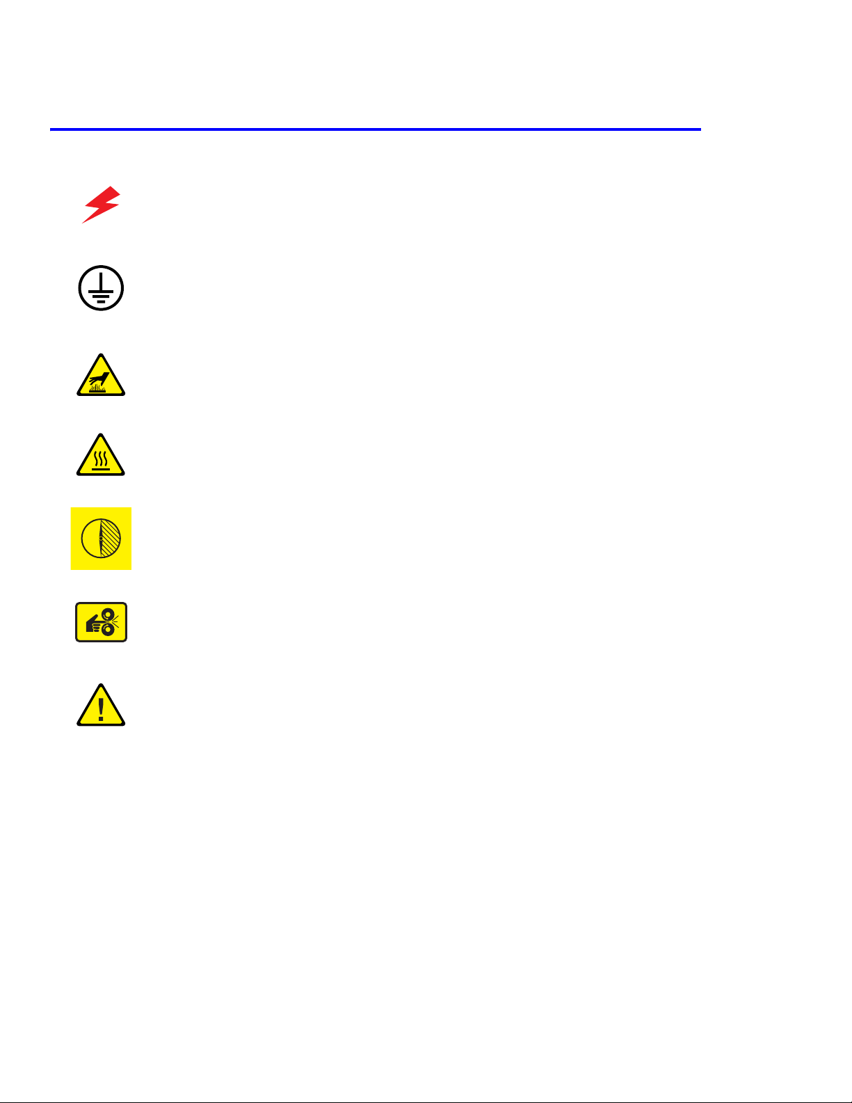
1.2 Symbols Marked on the Product
DANGER high voltage.
Protective ground (earth) symbol.
Hot surface on or in the printer. Use caution to avoid personal
injury.
0
30 min.
The surface is hot while the printer is running. After turning off
the power, wait 30 minutes.
Avoid pinching fingers in the printer. Use caution to avoid
personal injury.
Use caution (or draws attention to a particular component).
Refer to the manual(s) for information.
1-2
Page 11

Precautions
1.3 Power Safety Precautions
1.3.1 Power Source
For 110 VAC printers, do not apply more than 140 volts RMS between the supply conductors or between either
supply conductor and ground. Use only the specified power cord and connector. For 220 VAC printers, do not apply
more than 260 volts RMS between the supply conductors or between either supply conductor and ground. Use only
the specified power cord. This manual assumes that the reader is a qualified service technician.
Plug the power cord, with a grounding prong, into a grounded AC outlet only. If necessary, contact a licensed
electrician to install a properly grounded outlet. If the product loses its ground connection, contact with conductive
parts may cause an electrical shock.
1.3.2 Disconnecting Power
Turning the power off using the On/Off switch does not completely de-engergize the printer. You must also
disconnect the printer power cord from the AC outlet. Position the power cord so that it is easily accessible during
servicing so that you may power down the printer during an emergency. Disconnect the power plug by pulling the
plug, not the cord.
Disconnect the power cord in the following cases:
■ if the power cord or plug is frayed or otherwise damaged,
■ if any liquid or foreign material is spilled into the case,
■ if the printer is exposed to any excess moisture,
■ if the printer is dropped or damaged,
■ if you suspect that the product needs servicing or repair,
■ whenever you clean the product.
Service Manual 1-3
Page 12

Precautions
1.4 Electrostatic Discharge (ESD) Precautions
Some semiconductor components , and the respective sub-assemblies that contain them, are vulnerable to damage by
Electrostatic discharge (ESD). These components include Integrated Circuits (ICs), Large-Scale Integrated circuits
(LSIs), field-effect transistors and other semiconductor chip components. The following techniques will reduce the
occurrence of component damage caused by static electricity.
Be sure the power is off to the chassis or circuit board, and observe all other safety precautions.
■ Immediately before handling any semiconductor components assemblies, drain the electrostatic charge from
your body. This can be accomplished by touching an earth ground source or by wearing a wrist strap device
connected to an earth ground source. Wearing a wrist strap will also prevent accumulation of additional bodily
static charges. Be sure to remove the wrist strap before applying power to the unit under test to avoid potential
shock.
■ After removing a static sensitive assembly from its anti-static bag, place it on a grounded conductive surface. If
the anti-static bag is conductive, you may ground the bag and use it as a conductive surface.
■ Do not use freon-propelled chemicals. These can generate electrical charges sufficient to damage some devices.
■ Do not remove a replacement component or electrical sub-assembly from its protective package until you are
ready to install it.
■ Immediately before removing the protective material from the leads of a replacement device, touch the protective
material to the chassis or circuit assembly into which the device will be installed.
■ Minimize body motions when handling unpackaged replacement devices. Motion such as your clothes brushing
together, or lifting a foot from a carpeted floor can generate enough static electricity to damage an electrostatically sensitive device
■ Handle IC’s and EPROM’s carefully to avoid bending pins.
■ Pay attention to the direction of parts when mounting or inserting them on Printed Circuit Boards (PCB’s).
1.5Service Safety Summary
1.5.1 General Guidelines
For qualified service personnel only:
Refer also to the preceding Power Safety Precautions.
Avoid servicing alone: Do not perform internal service or adjustment of this product unless another person capable
of rendering first aid or resuscitation is present.
Use care when servicing with power: Dangerous voltages may exist at several points in this product. To avoid
personal injury, do not touch exposed connections and components while power is on. Disconnect power before
removing the power supply shield or replacing components.
Do not wear jewelry: Remove jewelry prior to servicing. Rings, necklaces and other metallic objects could come
into contact with dangerous voltages and currents.
Power source: This product is intended to operate from a power source that will not apply more then 260 volts rms
for a 220 volt AC outlet or 140 volts rms for a 110 volt AC outlet between the supply conductors or between either
supply conductor and ground. A protective ground connection by way of the grounding conductor in the power cord
is essential for safe operation.
1-4
Page 13

Precautions
1.5.2 Warning Labels
Read and obey all posted warning labels. Throughout the printer, warning labels are displayed on potentially
dangerous components. As you service the printer, check to make certain that all warning labels remain in place.
1.5.3 Safety Interlocks
Make sure all covers and the printer’s front panel are in place and all interlock switches are functioning correctly after
you have completed a printer service call. If you bypass an interlock switch during a service call, use extreme caution
when working on or around the printer.
CLASS 1 LASER PRODUCT
The Phaser® 6100 Color Laser Printer is certified to comply with Laser Product Performance Standards set by the
U.S. Department of Health and Human Services as a Class 1 Laser Product. This means that this is a class of laser
product that does not emit hazardous laser radiation; this is possible only because the laser beam is totally enclosed
during all modes of customer operation. When servicing the printer or laser unit, follow the procedures specified in
this manual and there will be no hazards from the laser.
1.5.4 Servicing Electrical Components
Before starting any service procedure, switch off the printer power and unplug the power cord from the wall outlet. If
you must service the printer with power applied, be aware of the potential for electrical shock.
Warning
Turning the power off by using the On/Off switch does not completely de-energize the printer. You must also
disconnect the printer power cord from the AC outlet. Position the power cord so that it is easily accessible
during servicing.
Warning
Do not touch any electrical component unless you are instructed to do so by a service procedure.
S7300-02
1.5.5 Servicing Mechanical Components
When servicing mechanical components within the printer, manually rotate drive assemblies, rollers, and gears.
Warning
Do not try to manually rotate or manually stop the drive assemblies while any printer motor is running.
S7300-03
Service Manual 1-5
Page 14

Precautions
1.5.6 Servicing Fuser Components
Warning
This printer uses heat to fuse the toner image to media. The fuser is VERY HOT. Turn the printer power off,
open Door B, and wait at least 5 minutes for the Fuser to cool before you attempt to service the Fuser
Assembly or adjacent components.
1.6 Regulatory Specifications
1.6.1 Federal Communications Compliance
The equipment described in this manual generates and uses radio frequency energy. If it is not installed properly in
strict accordance with Xerox instructions, it may cause interference with radio and television reception or may not
function properly due to interference from another device. However, there is no guarantee that interference will not
occur in a particular installation. If this equipment does cause harmful interference to radio or television reception,
which can be determined by turning the equipment off and on, the user is encouraged to try to correct the interference
by one or more of the following measures:
■ Reorient or relocate the receiver (device being interfered with).
■ Increase the separation between the printer and the receiver.
■ Connect the printer into an outlet on a circuit different from that which the receiver is connected.
■ Route the interface cables on the printer away from the receiver
■ Consult the dealer, Xerox service, or an experienced radio/television technician for help.
Changes or modifications not expressly approved by Xerox can affect the emission and immunity compliance and
could void the user's authority to operate this product. To ensure compliance, use shielded interface cables. A shielded
parallel cable can be purchased directly from Xerox at www.xerox.com/office/6100supplies
Xerox has tested this product to internationally accepted electromagnetic emission and immunity standards. These
standards are designed to mitigate interference caused or received by this product in a normal office environment.
This product is also suitable for use in a residential environment based on the levels tested.
In the United States this product complies with the requirements of an unintentional radiator in part 15 of the FCC
rules. Operation is subject to the following two conditions: (1) this device may not cause harmful interference; (2) this
device must accept any interference received, including interference that may cause undesired operation.
This digital apparatus does not exceed the Class B limits for radio noise emissions from digital apparatus set out in
the Radio Interference Regulations of the Canadian Department of Communications, ICES-003.
Le présent appareil numérique n'émet pas de bruits radioélectrique dépassant les limits applicables aux appareils
numériques de la classe B prescrites dans le Réglement sur le brouillage radioélectrique édicté par le ministere des
Communications du Canada, NMB-003.
.
1.6.2 Declaration of Conformity
Xerox Corporation, declares, under our sole responsibility that the printer to which this declaration relates, is in
conformity with the standards and other normative documents:
This product, if used properly in accordance with the user's instructions is neither dangerous for the consumer nor for
the environment. A signed copy of the Declaration of Conformity for this product can be obtained from Xerox.
1-6
Page 15

Reference Information
Reference Information
2
2. Reference Information
This section contains a tools list, list of abbreviations used in this manual, and a clearance required specification when
installing the Phaser 6100 printer.
2.1 Tools for Troubleshooting the Printer
The following tools are recommended for safe and easy troubleshooting as described in this service manual.
■ DVM (Digital Voltage Meter) standard: indicating more than 3 digits
■ Screwdrivers:
■ Tweezers
■ Cotton swabs
■ Cleaning equipment: Standard: dry, lint-free cloth and/ or mild detergent
■ Toner Type II Vacuum
■ Soft bristle brush
■ Printer Installer and Utilities CD-ROM
Service Manual 2-1
Page 16

Reference Information
2.2 Acronyms and Abbreviations
Definition Definition
ADC Analog-to-digital Conversion F/W Firmware
AP Access Point FCF/FCT Tray 1 or First Cassette Feeder
AC Alternating Current FISO Front In, Side Out
ASIC Circuit Application Specific Integrated FPOT First Print Out Time
Ass’y Assembly GDI Windows Graphic Device Interface
BIOS Basic Input Output Sytem GIF Graphic Interchange Format
BLDC Motor Brushless Dc Motor GND Ground
CMOS Complementary Metal Oxide
Semiconductor
CMYK Cyan, Magenta, Yellow, Black HDD Hard Disk Drive
CN Connector HTML Hyper-text Transfer Protocol
CON Connector HV High Voltage
CPU Central Processing Unit HVPS High Voltage Power Supply
CTD Sensor Color Toner Density Sensor I/F Interface
dB Decibal I/O Input/output
dBA A Weighted Decibel lb Pound(S)
dBm Decibel Milliwatt IC Integrated Circuit
DC Direct Current ICC International Color Consortium
DCU Diagnostic Control Unit IDE Intelligent/integrated Drive Electronics
DIMM Dual In-line Memory Module IEEE Institute Of Electrical And Electronics
DPI Pots Per Inch IOT Image Output Terminal (Color Printer,
DRAM Dynamic Random Access Memory IPA Isopropyl Alcohol
HBP Host Based Printing
Engineers, Inc.
Copier)
DVM Digital Voltmeter IPC Inter Process Communication
ECP Enhanced Capability Port IPM Images Per Minute
ECU Engine Control Unit ITB Image Transfer Belt (Transfer Belt)
EEPROM Electronically Erasable
Programmable Read Only Memeory
EMI Electro Magnetic Interference LBP Laser Beam Printer
EP Electro Photographic LCD Liquid Crystal Display
EPP Enhanced Parallel Port LED Light Emitting Diode
LAN Local Area Network
LSU Laser Scanning Unit
2-2
Page 17

Reference Information
Definition Definition
LVPS Low Voltage Power Supply Or SMPS
MB Megabyte Q’ty Quantity
MHz Megahertz RAM Random Access Memory
MPBF Mean Prints Between Failure ROM Read Only Memory
MPF/MPT Multi-purpose Tray SCF/SCT Tray 2 Or Second Cassette Feeder
NIC Network Interface Card SMPS Switching Mode Power Supply or LVPS
NPC Network Printer Card SPGPm Samsung Printer Graphic Processor
NVRAM Non-volitale Random Access Memory SPL Samsung Printer Language
OPC Organic Photo Conductor Spool Simultaneous Peripheral Operation Online
PBA Print Board Assembly SW Switch
PCI Peripheral Component Interconnect SURF Surface Rapid Fusing
PCL Printer Command Language Sync Synchronous
PDF Portable Document Format T1 ITB or Transfer Belt Imaging
PDL Page Description Language T2 Transfer Roller Imaging
Ping Packet Internet Or Inter-network
Grouper
PPD Postscript Printer Description PnP Universal Plug-n-play
PPM Pages Per Minute URL Uniform Resource Locator
PS Postscript USB Universal Serial Bus
PTL Pre-transfer (Erase) Lamp
PWM Pulse Width Moduration
TRC Toner Reproductive Curve
Service Manual 2-3
Page 18
Reference Information
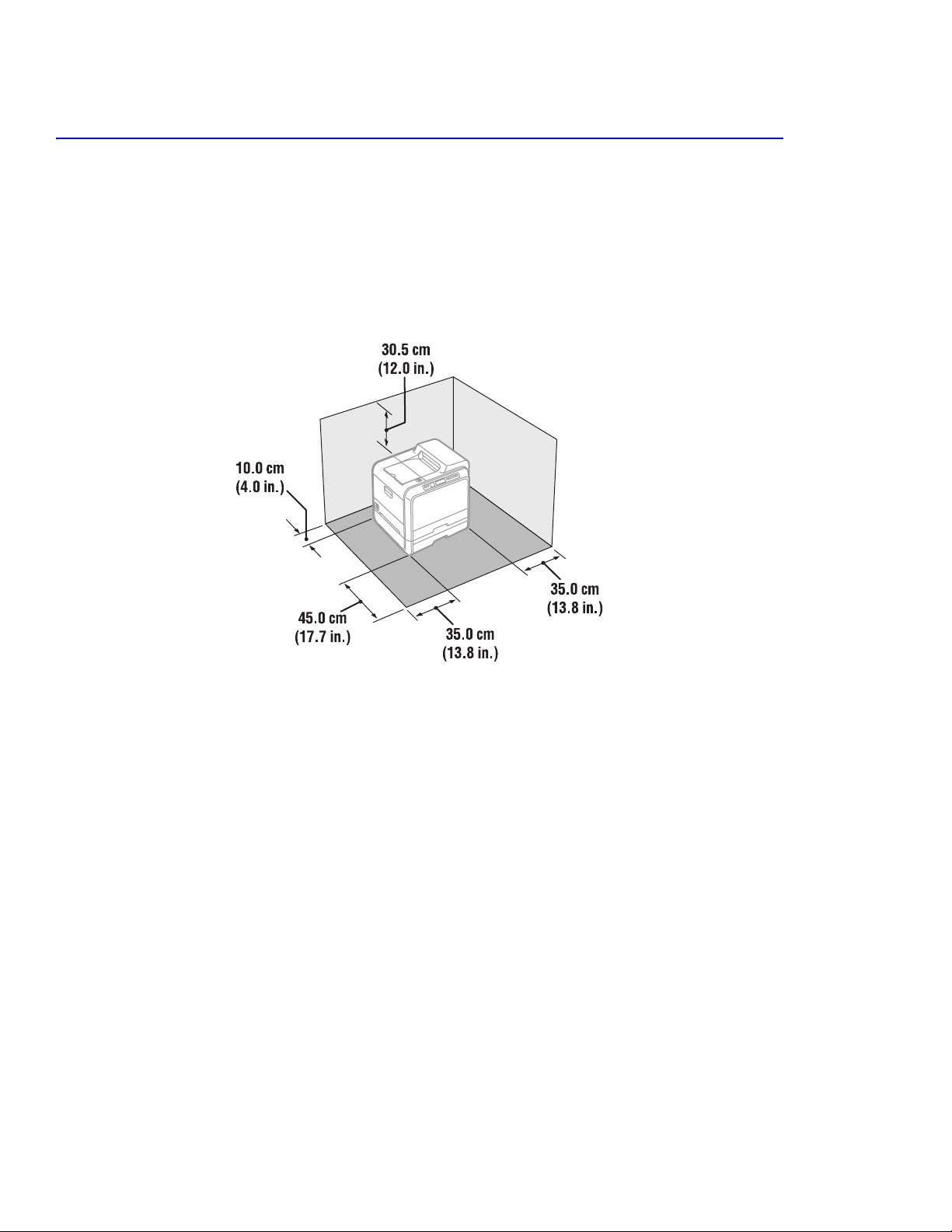
2.3 Selecting a Location for the Printer
■ Leave enough room to open the printer trays, covers, and allow for proper ventilation.
■ Provide the proper environment
■ A sturdy, level surface
■ Away from the direct airflow of air conditioners, heaters, or ventilators.
■ Free from extreme fluctuations in temperature, sunlight, or humidity.
■ Clean, dry, and free from excessive dust.
2-4
Page 19
Reference Information
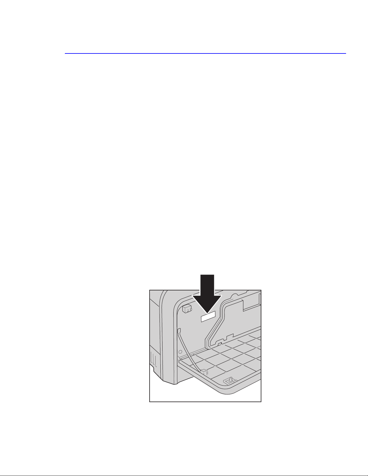
2.4 Printer Serial Number Format
Changes to Xerox products are made to accommodate improved components as they become available. It is
important when ordering parts to include the following information:
■ Component's part number
■ Product type or model number
■ Serial number of the printer
Serial numbering. Particular fields in the serial number indicate the modification level of the printer, the date of its
manufacture and the sequence number of the printer produced on that day.
The serial number is coded as follows:
■ RENXXXXXX - 110V Printer
■ REPXXXXXX - 220V Printer
■ 1st three alpha = Product Code
■ 1st numeric value = Revision of the Printer.
■ Remaining 5 numeric values indicate the printers serial number.
BD serial number ranges - 30,000~ 59,999
DN serial number ranges - 60,000 and above
Serial Number Example:
REN130159...
REN: 110V printer
1: revision 1
30159: serial number, BD configuration
Service Manual 2-5
Page 20

Reference Information
2-6
Page 21

Specifications
Specifications
3
The specifiations in this manual are correct at the time of printing. Product specifications are subject to change
without notice.
3.1 General Specifications
Item Description
Print Method Non-impact electro-photography
Developing system Non-magnetic, Mono-component, Non-contact method
Exposure System Semiconductor laser diode beam scanning
Fuser (toner fixing) Thermal rollers fusing with pressure (heat lamp: 800 watts)
Resolution True: 600 x 600 dpi
Addressable: 1200 x 1200 dpi
Warm-up time 110 and 220 volt units: 120 seconds (2 minutes from power on to ready)
FPOT Mono: Less than 15 seconds (Ready to 1st page out)
Color: Less than 24 seconds (Ready to 1st page out)
Feed Method MPT (Multi-Purpose Tray), Tray 1 (FCT-First CassetteTray),
Tray 2 (SCT-Second Cassette (Tray)
Dimensions Width: 510 mm (20.07 in)
Depth: 470 mm (18.5 in)
Height: 405 mm (15.94 in)
Weight Printer: 35 kg (77.2 lb) with consumables
Optional Tray 2: 3 kg (6.6 lb) with packaging
Acoustic Noise Standby: less than 41 dB
Printing: less than 48 dB (color)
Power Saver Mode Available, user settings enabled
Service Manual 3-1
Page 22

Specifications
3.2 Controller Specification
Item Description
Processor SPGPM (Samsung Printer Graphic Processor) Clock speed 120 MHz
Memory The controller has 64 MB SDRAM and 4 MB flash ROM on Board.
1 DIMM expansion slot for SDRAM DIMM Package: DIMM; 100-pin
Type: SDRAM
DIMM Type: Unbuffered (SEC Custom, support other products within SEC)
Error Checking: Non-parity
Speed: 120/133 MHz
Voltage: 3.3 V
Samsung proprietary design 64/128MB
(128 MB Not currently supported)
Emulation SPL-Color
Operating Systems Win 95/98/Me/NT/2000/XP, Mac OS 9 USB only, Linux
Interface One parallel port
IEEE 1284 -1994 compliant, (Bi-directional, ECP/Nibble/Byte Mode)
One USB port
USB v.2.0 compliant
Color-coded to meet WHQL requirements, connector must be Pantone 426C
One 10/100 BaseT NIC connector
- The printer supports an internal Network Interface Card (NIC), which can be
installed pre-configured at the factory. This NIC supports all of the major
Network Operating Systems, such as the Novell NetWare, TCP/IP, etc.
Interface switching Automatic
Interface time-out 5 min (max.)
Font Windows Font
Color Management ICC ICM V3.4
3.3 Electrical Specification
Item Description
Input Voltage Low voltage: 100-127 VAC High voltage: 220-240 VAC
Input Range 90-135 VAC 180-264 VAC
Nominal Frequency: +/- 47/63 Hz +/- 47/63 Hz
Frequency tolerance +3 Hz +3 Hz
Power Consumption Print mode: 450 watts or less
Standby mode: 160 watts
Sleep mode: 35 watts
3-2
Page 23

3.4 Environmental Range
Items Operating Storage (packaged) Optimum
Specifications
Temperature
Humidity 20 - 80% RH 20 - 80 % RH 30 - 70% RH
Altitude 2,500 meters (8,200 feet)
15 ~ 30oC (59 ~ 86oF) 5 ~ 35 oC (41 ~ 95oF) 20 - 25 oC
3.5 Periodically Replaced Parts
Item Life Expectancy
Imaging Unit 50,000 images User replaceable
Transfer Belt 50,000 images User replaceable
Fuser 100,000 pages mono / 50,000 pages color User replaceable
Transfer Roller (T2) 50,000 pages (simplex prints) User replaceable
Waste Toner Cartridge 3,000 to 5,000 pages (color 5%) User replaceable
Printer 300,000 images or 5 years
3.5.2 Consumables
Item Life based on 5% coverage
Standard Toner Cartridge: Black
High capacity
Standard Toner Cartridge: Cyan
High capacity
Standard Toner Cartridge: Yellow
High capacity
Standard Toner Cartridge: Magenta
High capacity
3,000
7,000
2,000
5,000
2,000
5,000
2,000
5,000
3.5.3 Options
Item Description
Tray 2 (SCT) Paper capacity: 500 Sheets (20lb.)
Paper weight: 60 ~ 90 g/m
2
(16 - 24 lb)
Service Manual 3-3
Page 24

Specifications
3.6 Media Specifications
3.6.1 Paper Size and Weights
The supported media types for this printer include, but are not limited to: labels, envelopes, cardstock, plain paper,
transparency, letterhead and colored paper.
Paper Type Size Tray Support
A4 210 x 297mm All Trays
Letter 8.5” x 11” (216 x 279 mm) All Trays
Folio (Legal 13”) 8.5” x 13” (216 x 330 mm) MPT
Legal (Legal 14”) 8.5” x 14” (216 x 356 mm) MPT
Executive 7.25” x 10.5” (184 x 267 mm) MPT
Statement 5.5” x 8.5” (140 x 216 mm) MPT
ISO B5 176 x 250 mm MPT
JIS B5 182 x 257 mm MPT
A5 148 x 210 mm MPT
A6 105 x 148 mm MPT
Com-10 Envelope 4.15” x 9.5” (105 x 241 mm) MPT
#9 Envelope 3.88” x 8.88” MPT
Monarch Envelope 3.88” x 7.5” (98 x 191 mm) MPT
DL Envelope 110 x 220 mm (4.33” x 8.66”) MPT
C5 Envelope 162 x 229 (6.38” x 9”) MPT
C6 Envelope 114 x 162 (4.5” x 6.38”) MPT
B5 Emvelope MPT
OHP Transparency*, Paper Label, Card stock MPT
Custom size paper 90 x 140 mm (3” x 5”)
216 x 356 mm (8.5” x 14”)
* Transparencies CANNOT
white) ONLY
.
be used for color prints in this printer. monochrome (black and
MPT
3-4
Page 25

3.6.1 Paper Size and Weights (cont’d)
Tray Support Media Types / Capacity Sizes Weight
Specifications
Tray 1
Tray 2
MPT
Auto Duplex
Output Tray
Paper; 250 sheets (20 lb)
Paper; 500 sheets (20 lb)
Paper; 100 sheets
Envelope; 10
Label; 10 sheets
Transparency; 30 sheets
Card stock; N/A
Paper A4, Letter, Folio, Legal 20 ~ 24 lb
Paper; 250 sheets (20 lb)
A4, Letter 16 ~ 24 lb
A4, Letter, Legal, Folio, Executive,
A5, ISO and JISB5, A6, Statement,
Monarch, COM10, #9, C5, B5 Env.
and DL
3.6.2 Print Margins and Skew
Print Margins
Side print position accuracy +/- 2.0 mm (+/- 0.08”)
Lead print position accuracy +/- 3.0 mm (+/- 0.12”)
Skew
A rectangular box of 189 mm x 256 mm will be used to measure skew.
60 ~ 90 gsm
16 ~ 43 lb
60 ~ 163 gsm
75 ~ 90 gsm
b
Simplex Tray 1, 2 MPT
A: Vertical < 2.0 mm (+/- 0.08”) < 2.0 mm (+/- 0.08”)
B: Horizontal < 1.5 mm (+/- 0.06”) < 1.5 mm (+/- 0.06”)
Duplex
1.5 times simplex printing
3.6.3 PC (Host) Specifications
For reliable operation, the following PC configurations are recommended:
■ Windows 98, Me; Pentioum 166 MHz; 64 MB RAM
■ Windows NT 4.0, 2000, XP, Server 2003; Pentium 233 MHz; 128 MB RAM
■ Mac OS9; USB only; Power Macintosh G3, G4, iMac, PowerBook, iBook
■ All; 200 MB free hard drive space, CD-ROM Drive
a
Service Manual 3-5
Page 26

Specifications
3-6
Page 27
Product Summary
HVPS
Eraser Lamp
DEV. - Black
DEV. - Yellow
Pick-up
Roller
DEV. - Magenta
DEV. - Cyan
CASSETTE
LSU
Feeder
DUPLEX
Fuser Unit
EXIT Unit
MPF
SCF
Deve Cover
Transfer
Belt
Transfer
Roller
Imaging Unit
w/OPC Drum
PTL
SCF Path
Pick-up
Roller
Pick-up
Roller
4
4.1 System Structure
4.1.1 Major Assemblies of the Printer
Summary of Product
Fuser Unit
EXIT Unit
HVPS
Roller
Transfer
Belt
Transfer
PTL
DEV. - Black
Pick-up
DUPLEX
Eraser Lamp
Imaging Unit
w/OPC Drum
DEV. - Yellow
DEV. - Magenta
LSU
DEV. - Cyan
Roller
Feeder
Roller
Pick-up
Tray 1
MPT
Roller
Pick-up
Tray 2
Deve Cover
Service Manual 4-1
Page 28
Summary of Product
Conrtoller Board
Deve Cover
Open S/W
(Interlock Door A)
Front View
Control Panel
Rear View
Deve OEM
Board
CRUM
Reader
Waster Toner Sensor
Waster Toner Motor
Deve DriveDeve Drive
Duplex Cover
Duplex Cover
Open Switch
Open Switch
4-2
Fuser FanFuser Fan
Main DriveMain Drive
LVPSLVPS
Deve Drive
Deve Drive
Board
Board
Deve Cover
Open S/W
(Interlock Door A)
Conrtoller Board
Page 29

Summary of Product
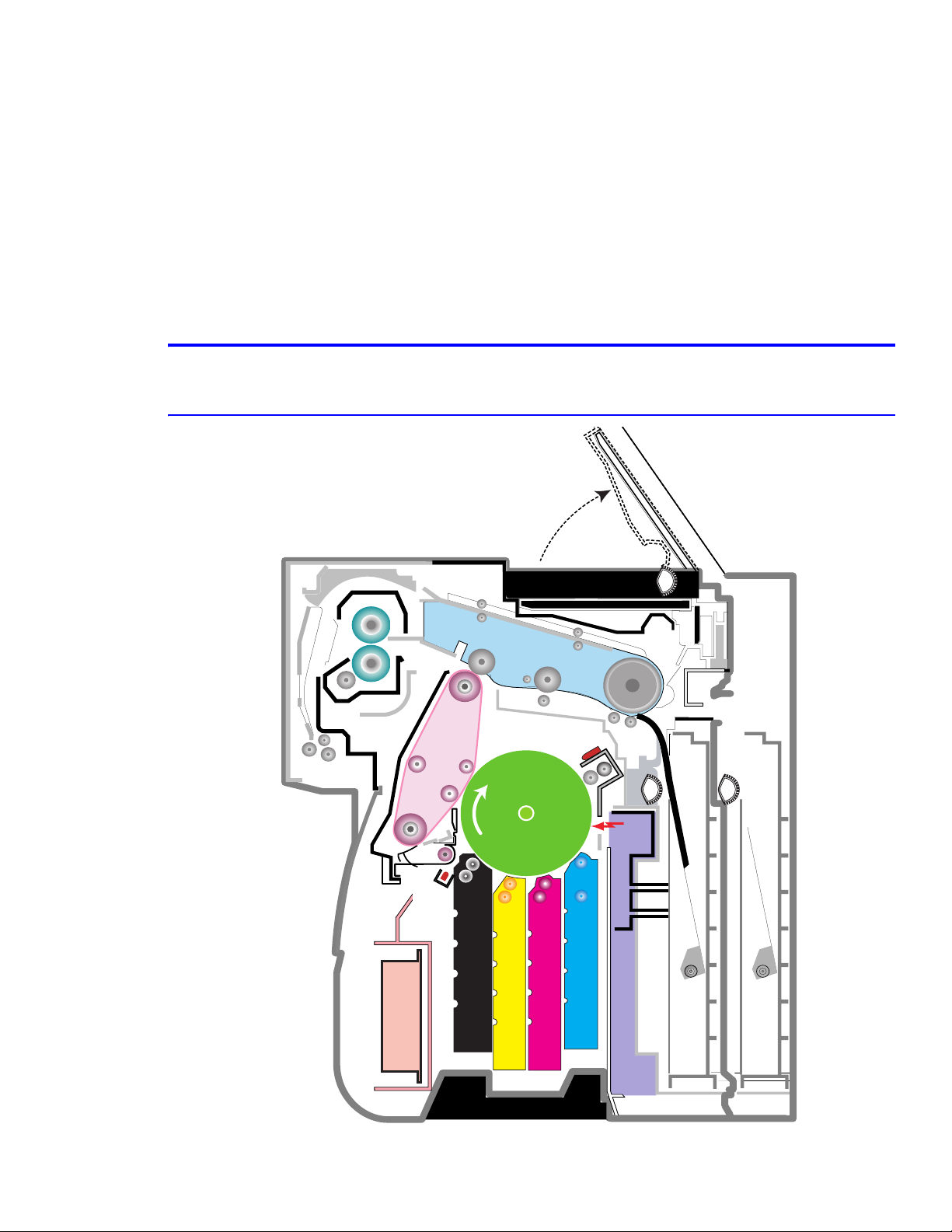
1) Imaging Unit
The imaging unit creates the image using an electro-photo process. The imaging unit consists of the following:
■ An OPC Drum
■ Waste Toner Assembly
■ Charge Roller Assembly
2) Transfer Belt (ITB)
ITB stands for Image Transfer Belt. The image developed on the drum is transferred first to the transfer belt. This
is called the T1 transfer (Primary Image Transfer).
■ The printer uses a four pass process to place the image on the transfer belt.
■ The image is created on the drum and transferred to the transfer belt in the following order: first yellow (Y),
then magenta, then cyan, and finally black.
3) Transfer Roller
Once the transfer of the image from the drum to the belt is complete, the full image is transferred from the belt to
the transfer roller. The transfer roller then transfers the image to paper. This is called the T2 transfer (Secondary
Image Transfer).
4) Tray 1 or FCT (First Cassette Tray)
Tray 1 stores and feeds paper to the printer. A pick roller picks paper, controls drive, feeds paper, and removes
static electricity from the paper.
Tray 1 Specifications:
■ Paper Feed: side registration
■ Paper Direction: Long edge
■ Paper Discharge: Separation Claw
■ Capacity: 250 Sheets
■ Paper Size: A4, Letter
■ Paper Weight (average): 60~90gsm (16~24lbs)
■ Paper Type: *see the approved Xerox media specifications in Section 3.
5) Tray 2 SCT (Second Cassette Tray) (contained in the Optional 500-Sheet Feeder)
Same as Tray 1, but holds up to 500(20 lb) sheets of paper.
6) MPT (Multi Purpose Tray)
The Multi-Purpose Tray supports custom size media and manual feed.
MPT Specifications:
■ Capacity: Cut Sheet: 100 Sheets (75 gsm / 20lb)
■ OHP: 30 Sheets, Envelopes, Labels, and Card Stock: 10 Sheets
■ Paper Arrangement: Side Registration
■ Drive: Main Motor (Brushless DC (BLDC))
■ Driving Management: Solenoid
■ Paper Discharge: Friction Pad Method
■ Paper Size: Legal, Folio, A4, Letter, Executive, JIS B5, A5, A6, Statement, Monarch (7 3/4), #9, C5, B5
Envelope, DL
■ Paper Weight and Type: See the approved Xerox media specifications in Section 3.
■ Paper Empty Sensor
Service Manual 4-3
Page 30

Summary of Product
7) Feeder
■ Paper Arrangement: Side Registration.
■ Drive: Main Motor DC
■ Paper Management: Feed Clutch
8) Duplex Unit
The duplex unit is used to reverse paper feed to print the on backside of paper. The duplex unit is not an option.
The transfer roller is part of the duplex unit.
Duplex Unit Specifications
■ Drive: Main Motor DC
■ Paper Reversal: After the front side of the original document is printed and begins reaches the exit path, the
exit roller pulls the paper back through the duplex unit for printing on the reverse side.
9) Exit Unit
The exit unit guides the paper to the output tray.
Exit Unit Specification
■ Capacity : 250 sheets standard (20 lb)A4/Letter (There is no output tray full sensor)
■ Paper Direction: Face Down
■ Exit Roller Drive: Driven by the main motor DC, rotating clockwise for normal feed and counter-clockwise
to reverse feed for duplex printing.
10) Toner Cartridges
There are four toner cartridges, one each for C (Cyan), M (Magenta), Y (Yellow) , and K (Black).
11) Fuser Unit
The fuser unit consists of 2 heat lamps, 2 heat rollers, 2 thermostats and one thermister. After the image is
transferred from the transfer roller onto the media, the fuser melts and fuses the toner to the paper by applying
pressure and heat to complete the print job.
12) Laser Unit (LSU)
The laser unit forms the latent image on the surface of the drum using a static charge.
13) Main Motor (Brushless DC)
The main motor drives the following components: imaging unit, transfer belt, feeder, fuser, exit, and duplex unit.
Main Motor Specification:
■ Power: 40W Max (24V)
14) DEVE Drive Motor
The DEVE motor drives the toner cartridges and transfer belt cleaning cam.
DEVE Motor Specification:
■ Power : 40W Max (24V)
4-4
Page 31

Summary of Product
15) Low Voltage Power Supply (LVPS or SMPS (Switching Mode Power Supply))
The LVPS uses the AC supply voltage to generate the DC voltages used by the printer.
■ The LVPS has 3 output channels (+3.3V, +5V, +24V).
■ The LVPS sends AC power to the fuser and DC voltages to the cover interlock switches, and to the main
board.
■ The LVPS generates power to the, motors, clutches, waste toner motor and the CRUM reader board
(DEVE_OEM board).
■ AC heater control unit supplying power to the fuser is also located on the LVPS.
16) HVPS (High Voltage Power Supply)
The HVPS creates the high voltages used for the electro photographic process.
■ The high voltage is created from the 24V line from the LVPS.
■ High Voltage output is supplied to the charge roller, toner cartridge, imaging unit (T1), transfer belt (T2),
and transfer roller.
17) Main Board
The main board receives DC voltages from the LVPS to control the sensors, fuser fan, imaging components, main
motor and HVPS.
The main board has several major function blocks.
■ CPU Block: Creates bitmap data for the engine to print and controls various devices that are needed to
operate the printer.
■ Engine Control Block: Manages images and controls motors, clutches, and solenoids.
■ Memory Block : Stores video data and print orders from the computer.
■ ROM Block : The printer operating system and PDL interpreter are stored here.
■ USB 2.0 Block, IEEE 1284 Block, Option Block, and Control Panel.
18) DEVE Drive Board
Each toner cartridge requires high voltage when that color is being processed. The DEVE drive board, using four
solenoids, selects which cartridge is to receive the supply voltage. The DEVE board also controls the DEVE
motor, DEVE clutch, and DEVE solenoid drives. These are activated in sequence as required by the print
process.
19) DEVE_OEM Board (CRUM Reader)
The DEVE_OEM board verifies the toner cartridges are new, used and whether they are Xerox parts. An error
message will display on the front panel if the toner cartridge is a non-Xerox toner cartridge.
20) Waste Toner Assembly
A cleaning blade removes waste toner from the drum after every image is transferred to the transfer belt. Once
the complete image is transferred from the transfer belt to paper, the transfer belt cleaning solenoid activates and
another cleaning blade removes waste toner from the transfer belt. All the waste toner is then transferred to the
waste toner cartridge.
Replace the Waste Toner Cartridge immediately if the error message “Waste Toner Cartridge Full/ Not Installed”
is displayed on the control panel.
Caution
Failure to have a waste cartridge installed or replaced when full can damage the printer.
Service Manual 4-5
Page 32

Summary of Product
3. Fuser Fan
1. Main Motor
2. DEVE Motor
4. Waste Toner Motor
4.1.2 Motor and Fan Layout
1. Main Motor
1. Main Motor
3. Fuser Fan
3. Fuser Fan
2. DEVE Motor
2. DEVE Motor
4. Waste Toner Motor
4. Waste Toner Motor
No. Name Description
1. Main Motor Drives the imaging unit, transfer belt, feed, fuser, exit and duplex unit.
2. DEVE Motor Drives the toner cartridges and transfer belt cleaning cam.
3. Fuser Fan Cools the fuser.
4. Waste Toner Motor Transfer collected waste toner from the imaging unit and transfer belt
to the waste toner cartridge.
4-6
Page 33

4.1.3 Clutch and Solenoid Layout
Transfer Belt
Home Solenoid
Duplex Solenoid
Transfer Belt
Cleaning
Solenoid
Summary of Product
Cartridge Solenoid(C, K, Y, M)
Cartridge Solenoid(C, M, Y, K)
Transfer Belt
Home Solenoid
MP Pick_up
MPT Pick_up
Solenoid
Solenoid
Feed Regi
Clutch
Pick_up Solenoid
Black Deve
Black Deve
Clutch
Clutch
Yellow Deve Clutch
Yellow Deve Clutch
Magenta Deve Clutch
Magenta Deve Clutch
Cyan Deve Clutch
Cyan Deve Clutch
No. Solenoid Name Description
1. Y DEVE solenoid Controls high voltage to the yellow toner cartridge.
2. M DEVE solenoid Controls high voltage to the magenta toner cartridge.
3. C DEVE solenoid Controls high voltage to the cyan toner cartridge.
4. K DEVE solenoid Controls high voltage to the black toner cartridge.
5. Pickup solenoid Controls drive to the pickup roller.
6. MPT pick solenoid Controls drive to the MPT pick roller.
7. Duplex solenoid Reverses rotation of the main motor during duplexing
8. Transfer belt home solenoid Engages and disengages the transfer roller from the transfer belt.
9. Transfer belt cleaning solenoid
Operates the transfer belt cleaning blade.
(cam)
No. Clutch Name Description
1. Y DEVE clutch Controls the yellow toner cartridge drive.
2. M DEVE clutch Controls the magenta toner cartridge drive.
3. C DEVE clutch Controls the cyan toner cartridge drive.
4. K DEVE clutch Controls the black toner cartridge drive.
5. Feed Clutch Controls registration of the paper pick.
Service Manual 4-7
Page 34

Summary of Product
DEV. - Black
DEV. - Yellow
Pick-up
Roller
DEV. - Magenta
DEV. - Cyan
CASSETTE
Feeder
DUPLEX
Fuser Unit
EXIT Ass'y
MPF Path
Duplex Path
MPF
Imaging
Unit
SCF
Transfer
Belt
SCF Path
4.1.4 Sensor and Switch Layout
Exit Sensor
EXIT Unit
Duplex Path
Fuser Unit
Transfer
Unit
Belt
DUPLEX
Feeder
Paper Pick-Up Roller
Transfer Roller
Feed Sensor
MPT Path
DEV. - Black
DEV. - Yellow
DEV. - Magenta
DEV. - Cyan
Imaging
Tray 1
Path
Tray 2
Path
Paper Empty Sensor(SCT)
Paper Empty Sensor(FCT)
No. Name Description
MPT
Paper Empty
Sensor(MPT)
1. Tray 1 paper empty sensor Detects absence of paper in Tray 1.
2. Tray 2 paper empty sensor Detects absence of paper in Tray 2.
3. MPT paper empty sensor Detects absence of media in the MPT.l
4. Feed sensor The feed sensor is used to detect a jam condition if paper does not
pass the sensor within a specified amount of time after paper is
picked.
5. Transfer belt home sensor The sensor detects the transfer belt start location for image transfer,
ensuring that all four color images are registered correctly.
6. CTD sensor The color toner density sensor detects toner density for each color
transferring to the drum.
7. Waste toner sensor Detects amount of toner in the waste cartridge, and if a waste
cartridge is installed. See page 4-2 for location of sensor.
Detects the open or closed condition of the DEVE cover (Door A). See
page 4-2 for location of sensor.
Detects the open or closed condition of the Duplex cover (Door C).
See page 4-2 for location of sensor.
8. Exit sensor Detects whether or not media has exited the printer.
9. DEVE cover open switch
10. Duplex cover open switch
Note
(Door A interlock)
(Door C)
The transfer belt home sensor and CTD sensor are located in the transfer belt. If these sensors become
damaged or faulty, replace the transfer belt assembly. The sensors are not spared separately.
4-8
Page 35

4.1.5 Main Board
DEVE_DRIVER
PA NE L
HVPS
ITB
CN4
CN7
CN10
NPC
USB
Summary of Product
Parallel Port
DEVE_DRIVER
DEVE_DRIVER
LSU SW
ERASER
LSU_FAN
WASTE TONER
CN17
PTL
TH4
TH3
CN11
CN13
CN15
NIC
CN9
For Test
CN1
CN5
LSU
CN12
SCF
CN16
CN8
CN14
OPC KEY
CN6
CN35
CN19
EXIT
CN24
DUPLEX
CN26
T2 HOME
CN27
BLDC1
CN28
FSR_ROLL
CN29
FUSER_FAN
CN30
SMPS
CN30
CN32
MP SOL
MP EMPT
CN33
FEED
CN25
CN23
CN21
PICK_UP
EMPT
CLT_FEED
Service Manual 4-9
Page 36

Summary of Product
FLASH MEMORY
ENGINE CONTROL
DIMM
RAM
SPGPm
Main Control
4-10
Page 37

Summary of Product
Flash Memory
4MB
5pin UART
Panel
16x2 L C D
(W-LAN)
NOT SUPPORTED
SPGPm
EEPROM
2048 bytes
SDRAM
64MB
SDRAM DIMM
34MB~128MB
USB 2.0
LPEC 1
Engine
Control
Block
1) CPU BLOCK
A 120MHz - 32bit RISC processor is used to manage commands and data supplied by the host. This is converted
into a bitmap image which is passed to the engine block for printing.
2) SPGPm (Samsung Printer Graphics Processor) overview
■ Package: 272 pins PBGA
■ Power: 1.8V(Core), 3.3V(IO) power operation, P1284 inputs : 5V tolerant
■ Speed: 120MHz core ( ARM946ES) operation, 60MHz bus operation,
supportable engine speed: under 30ppm
■ Dual bus architecture for bus traffic distribution:
AMBA High performance Bus (AHB)
System Bus with SDRAM
■ Integrated ARM946ES: 32-bit RISC embedded processor core
■ Direct connection up to 5 SDRAM arrays:
SDRAM controller supports PC-66, PC-100 and PC-133 SDRAMs running at 60MHz
Up to 128MB per array, up to 512MB totally
Wide supports for various SDRAM configurations, including programmable band and column address
Programmable SDRAM refresh time interval
■ IEEE1284 compliant parallel port interface
Compatible ECP communications are supported
Direct support for IEEE1284 compliant data transceivers
■ High performance DMA based Interface to Printer Engine
■ Engine Controller
Motor Control Unit: Motor Speed Lookup Table Memory (128 x 16 x 2)
Pulse Width Modulation Unit
ADC Interface Unit
LSU Interface Unit
■ Ethernet Controller (MAC)
Full compliance with IEEE standard 802.3, 802.3u specification
Support 10/100 Mbps data transfer rates
Service Manual 4-11
Page 38

Summary of Product
■ USB 2.0 interface
USB 1.1 backward compatible UDC (USB Device Controller) block and USB Physical block are integrated
Both of High Speed (480 Mbps) and Full Speed (12 Mbps) are supported
2 DMA channels support: one RX Channel and one TX Channel
3) Memory Block
The operating program runs from memory (see below). It is used to store video data and print jobs from the host.
Standard factory fitted memory is 64MB, and can be expanded using a DIMM module mounted in the SODIMM
connector. DIMMs from 64Mb - 128MB can be used giving a total of up to 192MB of memory.
modules are non-standard and not currently supported
controls the SDRAM memory connected using a 32 bit 60 MHz bus.
. The memory controller is located in the SPGPm
Note: DIMM
4) ROM Block
An 2MB flash ROM is used to store the OS. After power on, the contents of ROM are downloaded into memory
and the OS is run from within memory.
5) USB 2.0 Block
Is used to provide support for USB 2.0 and is capable of interface speeds up to 480 Mbps.
6) IEEE 1284 Block
An IEEE 1284 controller is controlled directly by the SPGPm processor. ECP mode is supported.
7) Option Block
An Ethernet card can be attached using the 100 pin connector. It is connected directly to the SPGPm processor
and communicates using a 16 bit bus.
8) Control Panel
The control panel is controlled by a UART Block located in the SPGPm.
9) Memory
There are two types of memory, program memory; that uses flash and a working memory that uses SDRAM.
10) Sensors
Various sensors are used to detect various conditions during the print process.
11) Actuator Control
Drives the various motors and clutches that are required for the paper feed and print process.
12) ADC (Analog to Digital Conversion)
Detects the current of: imaging unit, transfer belt, transfer roller, and fusing temperature, waste agitator, DC
motor CRUM reader board, set temperature, and CTD sensing.
13) DAC
Controls the output of the LED on the CTD Sensor.
4-12
Page 39

Summary of Product
CON4
CON3
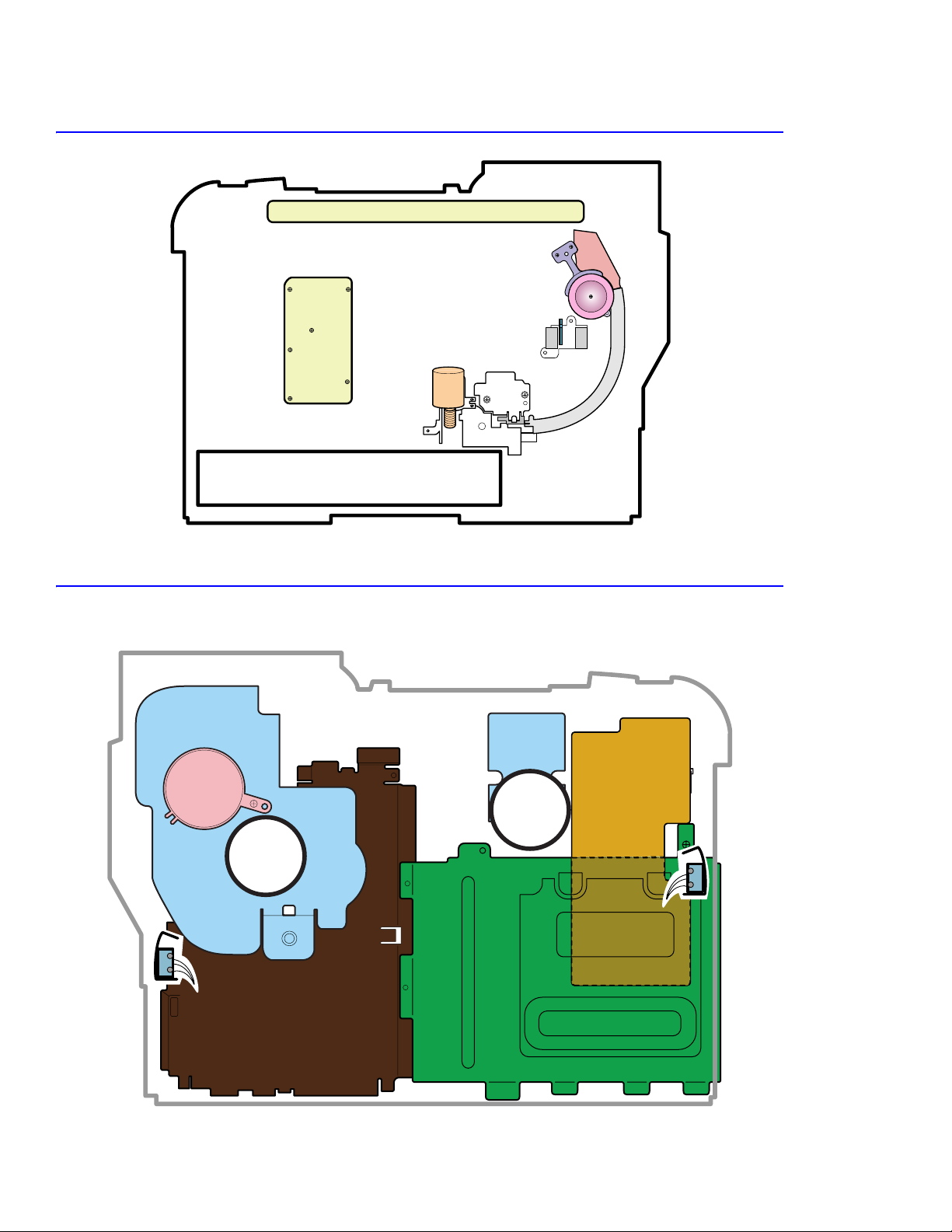
4.1.6 LVPS (SMPS) Board
The LVPS board supplies DC power for driving the whole system, it also contains an AC heater control unit that
supplies power to the fuser.
1) DC output
Main board, control panel, Tray 1, developer drive board, interlocks, sensors imaging components, motors,
clutches, solenoides and HVPS.
2) AC output
Fuser
3) Output voltage
No. Item CH1 CH2 CH3 CH4
1. Channel Name +3.3 V +5 V +24 V +24 V
2. Rated output voltage 3.3 V +/-4% +5 V +/-4% +24 +15%/-10% +24 V +15%/-10%
3. Uses MICOM,
CMOS LOGIC
MICOM,
CMOS LOGIC
MOTOR, FAN MOTOR, FAN
CON4
CON4
CON3
CON4
CON3
CON3
CON1
CON2
CON1
Fuse
CON2
Service Manual 4-13
Page 40

Summary of Product
SUPPLY
T1
T2
CN1
CN2
CHARGER
4.1.7 HVPS (High Voltage Supply) Board
The HVPS uses the +24 volts supplied by the LVPS to generate the high voltages used by the charge roller, toner
cartridge, imaging unit (T1), transfer belt (T2), and transfer roller. For the best print-quality images, these hifh
voltages must be controlled and maintained accurately.
Warning
High Voltage! Be sure to follow the steps outlined in Section 1.5.4 when servicing this assembly.
T1 T2
CHARGER
SUPPLY
CHARGER
CHARGER
SUPPLY
SUPPLY
CN1
CN1
CN1
CN2
CN2
CN2
T1
T1 T2
T2
4-14
Page 41

Summary of Product
1) Charging Voltage: Charger
■ Function: Charges the surface of the drum to about -500 volt ~ 800 volt.
■ Output voltage: -200 V~-2.0K V DC +/- 3% (Duty is changeable, no loading)
■ Error type: If the correct voltage was not present, the surface of the drum is not charged. As a result, toner
on the developer roller transferred to the drum could produce entirely black prints.
2) Transfer high voltage: T1(+)
■ Function: Used to transfer toner from the drum to the transfer belt.
■ Output voltage: +400 V~ +3.5K V DC +/- 3% (Duty is changeable, no loading)
■ Error type: If the primary transfer voltage was not present, it is not possible to transfer toner from the drum
to the transfer belt. As a result, print output could be faint or blank.
3) Transfer High Voltage: T2 (+)
■ Function: Used to transfer toner from the transfer roller to the paper.
■ Output voltage: +400 V~ +5K VDC +/- 3% (Duty is changeable, no loading)
■ Error type: If the secondary transfer voltage was not present, it is not possible to transfer toner from the
transfer roller to the paper. As a result, print output could be fain or blank.
4) Cleaning voltage: T2 (-)
■ Used in the cleaning process to transfer/clean off the (-) negative toner reamaining on the transfer roller to
the waste toner cartridge.
■ Output voltage: There is no feedback control, and it outputs a fixed voltage (-900V).
■ Error type: Toner contamination occurs on the reverse side of the printed-paper.
5) Supplying voltage: Supply
■ Function: Supply the duplicated (AC+DC) voltage from the HVPS to the DEVE drive board.
■ Output voltage
■ AC Voltage F:1 KHz ~ 3 KHz (Duty is changeable)
■ AC Voltage Vp-p: 1 KV ~ 3 KV
■ DC : -100 V ~ -1000 V
■ Error type: 1. If this voltage is ground, print density is extremely low.
2. If this voltage is floating due to unstable contact points at the HV terminal, density becomes so low as that
printing results appear non-existent.
Service Manual 4-15
Page 42

Summary of Product
4-16
Page 43

System Outline
5
5.1 Color Laser Printing Process
5.1.1 Imaging Unit (Drum Charge Section)
The imaging unit contains the drum, waste toner cleaning assembly and charge roller.
Imaging Unit
OPC Drum
System Outline
Charge Roller
-1000V ~ -1500V
LSU
Charge Roller
Cleaning Roller
Charge Bias
Cleaning Blade
Waste Toner
Cartridge
Eraser Lamp
HVPS
1) Structure
■ OPC drum: The laser light forms a latent electric image on the surface of the drum.
■ Cleaning blade: Removes remaining unwanted toner from the drum.
■ Waste toner cartridge: Collects and stores the waste toner.
■ Charge roller: Charges with a negative high voltage (-1 KV~1.5 KV), while in contact with the drum and
produces a uniform (-) voltage on its surface of approximately -500~-800 V.
2) Type
■ Life span: 50,000 Images (Color 12,500 pages)
■ Waste toner removal: Transferred to a user replaceable tank
■ Waste cartridge sensors: LED type, detects cartridge presence and full
■ OPC drum diameter: 120 mm
■ Power: Main motor (BLDC)
■ Charge method: Charge roller
■ Eraser method: LED lamp (+5 V)
■ PTL (Pre-transfer lamp: LED lamp (+ V)
Service Manual 5-1
Page 44

System Outline
DEV. - Black
DEV. - Yellow
DEV. - Magenta
DEV. - Cyan
Drum
5.1.2 LSU (Exposure)
The latent image is formed on the drum using an image data stream to switch the laser beam On or Off. Where no
image is required the beam is off, where toner is required the beam is turned on. When the laser is on and the beam
strikes the drum surface, the charge is reduced to -50 V, where the beam is switched off the charge on the drum
surface remains at -600 V.
Unexposed Exposed Unexposed
-600V -600V
-50V
(30,000rpm)
Reflecting MirrorPolygon Motor
5.1.3 Toner Cartridge (Development Section)
In the development stage, toner particles are transferred from the toner cartridge onto the surface of the drum. The
drum and the developer roller rotate in opposite directions. Toner on the developer roller is charged to the developing
voltage. (see, page 5-7). Toner is attracted to the drum in those areas where the surface charge is -50V. Toner is not
attracted to those areas of the surface carrying a -600 V charge.
DEV. - Black
DEV. - Yellow
Drum
DEV. - Magenta
DEV. - Cyan
Dev Roller
Developing
Voltage
Dev Gap
OPC
Drum
1) Type
■ Developing method: Non-magnetic, Mono-component developing system.
■ Toner cartridge order: K, Y, M, C from top.
■ Developing sequence: Y, M, C, K
■ Life span: High Capacity Toner: 7,000 (K) / 5,000 (C, M, Y); Standard: 3000 (K) / 2000 (C,M,Y)
■ Power: DEVE motor (BLDC)
■ Power transmission: Electric clutch
■ Toner remaining: TRC (Toner Reproductive Curve) sensor, +Dot counting method
5-2
Page 45

2) Developing
The latent image is formed as described below.
Developing Sequence: Y, M, C, and K
T1 Process
The image is created using a four color pass
process. Each of the four colors is applied to the
drum one at a time in the following order: Y, M,
C, and then K.
The image formed on the drum is then
transferred to the transfer belt.
T2 Process
The full four color image formed on the transfer
roller, from the transfer belt, is then transferred
to the media.
Fuser and Exit
The image on the page is then fused and the
paper is ejected into the output tray.
Yellow ColorYellow Color
Magenta ColorMagenta Color
Cyan ColorCyan Color
Blacl BolorBlack Color
Paper Pick-up
Cleaning of
Transfer Belt
System Outline
Developing and Image Transfer
Developing and Image Transfer
Developing and Image Transfer
Developing and Image Transfer
Image Transfer to page
Fusing
3) Toner Cartridge Empty Detection
The toner cartridge empty state is detected by the
CRUM (NVRAM) contained in each cartridge.
Paper Exit
Service Manual 5-3
Page 46

System Outline
DUPLEX
5
5.1.4 Image Transfer
The toner image formed on the drum and transferred to the transfer belt is called the primary image transfer or T1.
When the final color image has been placed on the transfer belt it is then transferred onto the paper by the transfer
roller, this is called the secondary image transfer or T2.
1
2
3
6
4
OPC DRUM
Paper Path
No. Name Description
1. Transfer Belt (T1) Receives the four color image from the drum in Y, M, C, K order.
2. Image Transfer Cleaner After the final image is transferred onto paper by the transfer roller, any
toner left on the belt is removed using this cleaning blade.
3. PTL Pre-Transfer Lamp The pre-transfer lamp removes the charge holding the toner on the drum
allowing the toner to be transferred to the belt.
4. CTD Sensor This sensor monitors the density of each color toner being placed on the
drum. It is also used to detect a toner cartridge empty state.
The drum surface and toner have different light reflecting characteristics,
the CTD sensor uses this to detect the difference in the amount of toner
present on the drum.
Caution
Be careful not to contaminate the surface of the CTD sensor, this will
cause problems with color reproduction and quality.
Process: The TRC (Tone Reproduction Curve) control process is used
at power on, after waking from sleep mode, after every 100 pages of
printing, and after installing a new toner cartridge or OPC drum to check
the toner density transferred onto the OPC. Small patches of 6.25%,
25%, 37.5%, 50%, 62.5%, 75%, 87.5%, and 100% density for each of the
4 colors are deposited on the OPC drum surface and the CTD is used to
detect how much toner is transferred. Based on an internal calibration
curve the TCR control process adjusts the developer bias voltage to
ensure that optimal toner transfer takes place.
5-4
Page 47

System Outline
DUPLEX
r
DUPLEX
r
No. Name Description
5. Transfer Roller (T2) The transfer roller transfer the final toner image from the transfer belt to
the paper.
■ The HVPS applies the image transfer bias voltage to the transfer
roller allowing transfer of the image from the belt onto the paper.
■ When the image is to be transferred from the transfer belt to the
paper, the transfer roller pressure contact solenoid is activated and
this activates a cam which moves the transfer roller into contact with
the belt.
■ After the transfer has taken place, any remaining charge on the paper
is removed by applying a charge removal bias (generated in the
HVPS) to a detack saw.
Transfer method: Semi-conductive roller contact method
Effective transferring range: 218 mm (i.e. maximum image length)
6. Transfer Belt Home
Sensor
1. Primary Transfer (T1)
3. PTL (Pre-Transfer Lamp)
This sensor is used to ensure each color of toner is placed on the
transfer belt at the exactly the same location.
Image Transfer Belt
OPC DRUM
Image Transfer Rolle
HVPS
Primary Image Transfer Bias
Image Transfer Belt
PTL
(LED)
OPC DRUM
Image Transfer Rolle
Service Manual 5-5
Page 48

System Outline
4. CTD Sensor
CTD Sensor
Transfer Unit
OPC DRUM
5) Secondary Image Transfer, Transfer Roller (T2)
Image Transfer Belt
LED
TONER
Image Transfer Roller
OPC Drum
Charge Removal Bias
PBS (Polarized Beam Splitter)
PD (Photo Diode)
OPC DRUM
Paper
Image Transfer Bias
HVPS
5-6
Page 49

5.1.5 Fuser (Fusing Process)
Toner that has been through the primary and
secondary image transfer processes is fused or fixed
to the paper..
The fuser consists of two heat lamps, two heat
rollers, one thermistor, and two thermostats. The
fuser melts the toner onto the paper using pressure
and heat to complete the printing process.
Heat Lamp
(500W)
Heat Lamp
(300W)
System Outline
Heat Roller
Paper
Spring
Heat Roller
1) Thermostat (2)
The thermostats are temperature cut-off devices.If the heat lamps or heat rollers overheat, the thermostat turns off
power to the lamps to prevent fire.
2) Thermistor (1)
The thermistor detects the temperature of the heat roller’s surface, and feeds this information to the main
processor. The processor uses this information to control power to the fuser lamps in order to maintain a steady
temperature to the heat rollers.
3) Heat Roller (2)
Halogen lamps are used to heat the heat rollers. The heat rollers have a special Teflon surface which ensures that
any melted toner coming into contact with the heat roller surface does not stick. Paper passes between the two
rollers which evenly heat the paper from both sides to melt the toner and fusing it onto the media.
4) Safety Information - Warning
Overheat protection
1st level protection: Print engine is stopped if overheat
is condition is detected.
2nd level protection: Software turns off lamp power if
overheat condition is detected.
3rd level protection: Thermostat turns off lamp power if overheat condition is detected.
Protection device
Fuser power is turned off when the duplex cover or the toner cartridge door is open.
The printer keeps the surface temperature of the fuser cover under 80° C, and has a caution label attached inside
the exit cover where it can be easily seen by the user.
Service Manual 5-7
Page 50

System Outline
5.1.6 Exit
After passing through the fuser, media is ejected into the output tray. Any static electrical charge is removed by static
discharge brushes.
When operating in duplex print mode, after printing the front side of the page, the paper exit roller reverses to feed the
paper back into the printer in order to print on the back side of the paper.
5.1.7 Waste Toner Collection Process
Waste toner left on the drum and on the transfer belt is collected into the waste toner cartridge.
■ After transferring the toner image from the drum to the transfer belt, a cleaning blade removes waste toner
off the drum depositing it into the waste toner cartridge.
■ A second transfer belt cleaning blade removes waste toner from the transfer belt and deposits waste toner
into the waste toner cartridge.
1) Waste toner cartridge sensor
The waste toner cartridge sensor is used to detect the presence of the waste toner cartridge and its full condition.
> No waste toner cartridge
If a waste toner cartridge is not installed in the printer,
the waste toner sensor actuator blocks light from the
sensor LED and displays a cartridge not installed
message on the control panel.
> Low waste toner
If the sensors LED light reaches the photo sensor, by
passing through the waste cartridge, this indicates the
waste toner cartridge has not reached its full state.
> Waste toner tank full
If the sensors LED light is blocked or not received by the
photo sensor, it will indicate a waste toner cartridge full
state on the control panel.
Waste Toner Tank
Waste Toner Sensor
Waste Toner Sensor Actuator
Waste Toner Sensor
Waste Toner Sensor
5-8
Waste Toner TankWaste Toner Tank
Page 51

System Outline
5.2 System Start-Up Sequence
The printer uses 4 different colored toners (Yellow, Magenta, Cyan, Black) and is a color laser printer. Engine
firmware controls the print processes, drives the print engine, paper feed, developer, fuser, and paper exit systems. It
has both color and mono printing modes. During normal power up, the printer goes through four main stages:
Normal Power-ON
1. Initialize the system: This is silent as the main board is initializing.
2. Motors engage: All the motors engage and the printer checks the developer solenoids one at a time.
3. Laser engages / ADC Check: The laser unit engages and the printer applies patches of toner to the transfer belt
for the ADC toner density check.
4. Motors stop / Fuser Fan on: The printer quiets as all motors stop and the fuser fan starts.
5.2.1 System Initialization
1. Initialize ASIC
2. Initialize system variables
3. Initialize a virtual timer
4. Initialize fuser control
5. Initialize ADC
6. Establish ITB HOME interrupt
5.2.2 Warm-Up
During the warm-up stage, the following tasks are performed:
1. Self Test
■ System check
■ Cover open check
■ Device (Transfer Belt, Imaging Unit, Toner cartridge) check
■ Fuser check
■ Motion of motors, jams and paper empty check
■ Check feed and exit sensors. If paper is detected it is ejected. If the paper detection does not clear a jam,
recovery is carried out by the printer and the paper exit is instructed to drive for the maximum permitted
paper length.
2) Heat Control
The heater control unit separately manages the temperature of the heat lamps.
■ Target temperature 165° C
■ Temperature below 130° C - heat unit fully on,
■ Temperature above 135° C temperature is controlled by reading the temperature value every 10 msec.
3) TRC (Tone Reproduction Curve)
■ The TRC process (see page 5-4) is carried out and the developer bias voltage is determined.
4) Cleaning
■ Transfer rollers, imaging unit, and transfer belt are electrically and mechanically cleaned.
Service Manual 5-9
Page 52

System Outline
5.2.3 Ready
1) Host interface is monitored for print commands
2) Heat control
■ Target temperature (165° C).
■ Every 40 seconds, temperature value for the previous 250ms is read and a proportional control process is
carried out.
3) Printer is in “Ready” mode entered after warm-up or after completing a print job.
4) System Error check
5) Power save state is entered after timeout
Wakeup condition
■ When a “wakeup” order is received.
■ When a cover is opened or closed.
■ When the level of the paper empty sensor changes.
Heat lamp is off
5.2.4 Processing
There is a preparation stage before processing a print job and after receiving a print command.
1) Start Laser
■ Run scanning motor.
■ Check motor ready.
■ Turn LD on.
2) Start Main Motor, Eraser/PTL ON
■ Run main motor.
■ Check lock signal.
■ Run developer roll motor.
■ Check lock signal.
3) Turn High Voltage On
■ Charger ON.
■ Developer high voltage OFF.
4) Cleaning
■ Imaging unit and transfer belt cleaning.
5) Jam Check
5-10
Page 53

6) Motor Torque Check
7) Check and Set a High Voltage Condition (T1, T2, Charger)
8) Initialize Printing Parameters
■ Paper size, copies, trays
■ Image pixels, image times, y-offset, x-offset
■ Sensors
■ Color print mode:
■ Except legal & OHP/Legal/OHP
■ Simplex/Duplex
■ Mono print mode: Simplex/Duplex/OHP
5.2.5 Print
After sensing the transfer belt home position the following tasks are performed:
■ Send Psync signal to controller
■ Operates virtual timer for each color(Vdata)
■ Forms latent image on drum
■ Supplies toner on OPC drum
■ Transfers image to transfer belt (T1 )
■ Picks paper
■ Transfers image to paper (T2)
System Outline
1) Check Transfer Belt Home (Treated by Home interrupt every 3 seconds):
a. Transfer belt home sensing
b. If test mode is selected, a test pattern is printed.
c. A counter value is set up that addresses the timing to turn on page sync.
d. The virtual timer for each color (Y, M, C, and K) is set up.
e. If home is not detected every 3 seconds, an error is reported on the control panel.
2) Paper Path Printing
a. Paper is picked from Tray 1, Tray 2, or MPT
b. Control paper path
■ Paper pick stops when the leading edge of the paper reaches the feed sensor.
■ If the leading edge doesn’t reach the feed sensor, an error is reported.
■ While transferring the last color to the transfer belt, transports the paper.
■ Checks if the paper reaches the exit sensor in the specified amount of time, otherwise an error is reported.
■ Checks paper passing the exit sensor.
c. Jam check
■ Check paper reaching and passing the feed and exit sensors, otherwise an error is reported.
d. Duplex control
■ After passing the exit sensor, the duplex clutch is engaged to mechanically change the direction of the
paper in order to print the other side.
e. Printing sequence for each color
■ Uses a virtual timer for printing the colors in the correct sequence. (Yellow, Magenta, Cyan, Black)
A virtual timer is an algorithm for creating regular action at fixed time intervals. The standard setting is for a
5 msc timer interrupt.
Service Manual 5-11
Page 54

System Outline
5.2.6 Post-Print
This is the last stage of the printing process. Its functions are described below.
a. Clean transfer rollers.
b. Stops all virtual timers.
c. Re-initialize parameters used in the print process.
d. Stops motors.
5-12
Page 55

Disassembly
Disassembly
6
6.1.1 Precautions for Disassembly/Reassembly
■ Use only approved Xerox spare parts. Ensure that the part number, product name, any voltage, current or
temperature ratings are correct. Failure to do so could result in damage to the printer, circuit overload, fire or
electric shock.
■ Do not make any unauthorized changes or additions to the printer, this could cause the printer to malfunction and
create electrical shock or fire hazards.
■ When disassembling the printer, note where each screw goes. There are 19 different screws. Use of the wrong
screw could lead to system failure, short circuits or electrical shock.
■ Do not disassemble the laser unit. Once it is disassembled dust is admitted to the mirror chamber and will
seriously degrade print quality. There are no serviceable parts inside.
■ Regularly check the condition of the power cord, plug and socket. Bad contacts could lead to overheating and
fire. Damaged cables could lead to electric shock or component malfunctions.
6.1.2 Precautions When Removing Circuit Boards
Static electricity can damage a board, follow the ESD precautions in Section 1 of this manual when handling or
storing a board.
Precautions when moving and storing boards
■ Place boards in an approved anti-static discharge bag.
■ Do not store a board where it is exposed to direct sunlight.
Precautions when replacing boards
■ Disconnect power connectors first, before disconnecting other cables.
■ Do not touch any soldered connections, connector terminals, or other electronic parts when handling
insulated parts.
Precautions when checking boards
■ Before touching a board, touch a grounded area on the printer chassis to discharge any static electrical
charge on the body or wear an anti-static wrist strap.
■ Do not touch the board with your bare hands or metal objects, this can create a short circuit or cause an
electrical shock. Take extra care when handling boards containing sensors, motors or lamps as they may get
hot.
■ Take care when fitting, or removing, screws. Check for hidden screws.
Always ensure that the correct screw is used. When toothed washers are
removed, ensure they are refitted in their original positions.
Caution
Many of the parts are held in place with plastic latches. The latches break easily;
Remove them carefully. To remove such parts, gently pull the hook end of the
latch away from the part to which it is latched.
Service Manual 6-1
Page 56

Disassembly
6.2 Maintenance and Supplies
There are parts in this printer that have a limited life compared to the life of the printer, these parts must be
periodically replaced.
The table shows the life of each part and is measured using A4/Letter paper. When servicing a printer, always check
the status of these parts using the control panel and ensure that parts are replaced at the appropriate times. Otherwise
a general degradation in print quality can occur.
Item Life based on 5% coverage Auto Reset* Replaceable By
Black Standard Toner Cartridge
Black High capacity
Cyan Standard Toner Cartridge
Cyan High capacity
Yellow Standard Toner Cartridge
Yellow High capacity
Magenta Standard Toner Cartridge
Magenta High capacity
Imaging Unit 50,000 images Yes User replaceable
Transfer Belt 50,000 images No User replaceable
*Fuser 100,000 pages mono / 50,000
*Transfer Roller (T2) 50,000 pages (simplex prints) Yes User replaceable
Waste Toner Cartridge 3,000 to 5,000 pages (color
■ Page count values based on individual sides of paper printed (Duplex = 2 pages).
■ Image count value based on monochrome printed images.
■ When printing a color section 1 page = 4 images. (i.e. each side is made up of 4 color images)
3,000
7,000
2,000
5,000
2,000
5,000
2,000
5,000
pages color
5%)
Yes User replaceable
Yes User replaceable
Yes User replaceable
Yes User replaceable
No User replaceable
Yes User replaceable
The life span of each part is stored in memory. The amount of ‘life’ used can be checked at any time using the control
panel.
*When this part is replaced, it is necessary to reset the “life” used stored in memory.
To reset the fuser and transfer roller life usage from the printers control panel:
a. From the main menu select, Menu-Setup --> Maintenance --> Check other.
b. Select the appropriate part name from the list by using the Up Scroll and Down Scroll buttons
c. Select Reset.
6-2
Page 57

Disassembly
6.2.2 Printer Cleaning
The printer should be cleaned regularly, especially if it is used in a dusty environment. This ensures that print-quality
remains high and failures due to contamination are less likely to occur.
■ Clean the printer with a soft, lint free, cloth dipped in a mild detergent.
■ Do not touch the transfer roller when cleaning the inside of the printer. Grease and oils from the skin will
contaminate the surface and reduce print quality.
■ To clean the laser, open and close Door A a few times.
■ Please refer to the User Guide for more cleaning instructions.
Service Manual 6-3
Page 58

Disassembly
6.3 Information Related to Disassembly and Reassembly
Before diassembling the printer:
Caution
Do not use a power screwdriver for reassembling the printer. The plastic screw holes in the chassis can become
damaged or stripped. If holes are already damaged, use spare untapped holes. This printer uses 19 different
screw types, please refer page 6-5 for a list of all the screws used.
Note
Before disassembling the printer, always remove the toner cartridges, imaging unit and transfer unit. Protect the
assemblies from light, fingerprints and scratching. To prevent toner spills when removing the front cover, first
remove the waste toner cartridge and cover the openings with the caps provided.
6.3.1 Service Part Assemblies Warnings and Cautions
Do not disassemble or adjust the components listed below, these are spared as complete assemblies.
Warning
High Voltage! Be sure to follow the steps outlined in Section 1.5.4 when servicing this assembly
1) Laser Unit (LSU)
There are no serviceable parts inside the LSU. Alignment of the mirrors is critical. Opening the LSU will allow dust
into the laser and significantly reduce print quality.
with the LSU open or system interlocks disabled. Exposure to laser radiation can cause blindness
2) Transfer Belt (ITB)
Do not disassemble the ITB. The alignment of the home sensor is critical and is set up in the factory. Incorrect reassembly will cause print quality degradation.
3) Imaging Unit (OPC drum)
If the imaging unit is exposed to direct sunlight for a long time the parameters and response of the electrostatic
surface are changed, causing image transfer and print quality issues.
drum to prevent scratching Please use extra care to ensure the drum is protected from light and physical
contact when servicing the printer.
4) Toner Cartridges
Toner cartridges contain an extremely fine powder. Please keep toner cartridges away from children. The toner
powder contained in the toner cartridge can be harmful and if swallowed you should contact a doctor. Take care not to
spill toner - spillages should be cleaned with a Type II toner vacuum and cleaned up with cold water (hot water sets
the toner). Do not touch the developer roller surface as contamination will reduce print quality. Take care not to
damage the rollers surface when installing or removing a toner cartridge.
5) Developer (DEVE) Drive and Main Drive Assemblies
The alignment of the drive mechanism is critical and has been set by the factory. They are adjusted for the best
gearing alignment. If these motors are disassembled, misalignment will occur causing operational noise and image
problems: image alignment and toner distribution may be affected.
Warning: It is very dangerous to operate or service a printer
.
Caution: There is no protective shutter on the
6) Boards
Do not adjust the variable resistors on the boards. They have been already adjusted in the factory.
6-4
Page 59

Disassembly
7) Fuser Unit
Warning: The fuser melts toner onto the paper at a very high temperature, use care when handling the Fuser
or severe burns can result. When removing the fuser from a printer that has recently been operating, let the fuser
cool before handling. Do not touch the AC line (copper contact) on a main frame even after removing the fuser.
Screws Used in the Printer (Hardware Kit)
NO DESCRIPTION SPEC
S1 SCREW-MACHINE 2.6*4, GOLD
S2 SCREW-TAPPING 4*15, GOLD
S3 SCREW-TAPPING 3*8, GOLD
S4 SCREW-TAPTITE 2.6*6, GOLD
S5 SCREW-TAPTITE 3*8, BLACK
S6 SCREW-TAPTITE 2*10, GOLD
S7 SCREW-TAPTITE 3*6, GOLD
NO DESCRIPTION SPEC
S11 SCREW-TAPTITE 3*6, GOLD
S12 SCREW-TAPTITE 3*8, BLACK
S13 SCREW-MACHINE 3*8, SILVER
S14 SCREW-TAPTITE 4*10 SILVER
S15 SCREW-TAPTITE 3*6, GOLD
S16 SCREW-MACHINE 2*16, BLACK
S17 SCREW-TAPTITE 4*6, YELLOW
S18 SCREW-SPICIAL 3*10, BLACK
S8 SCREW-TAPTITE 3*10 SILVER
S9 SCREW-TAPTITE 3*6, GOLD
S10
SCREW-ASS’Y MACH
3*6, GOLD
S19 SCREW-TAPTITE 4*6, SILVER
S20 SCREW-TAPTITE 3*12, YELLOW
S21
COVER DIME SCREW
EMBERGOLD
Service Manual 6-5
Page 60

Disassembly
6.3.2 Removing Consumables
This section shows you how to open the covers (front cover, DEVE cover, exit cover, and duplex cover) and how to
remove and replace the consumable parts (toner cartridge, transfer belt, and imaging unit).
Orientation of the Printer Doors
1. Pull the side handle to open the DEVE cover (Door A) and then press down firmly until the toner cartridges are
ejected.
Note
Before opening the exit cover, completely open the DEVE cover, 90o to the main frame, ejecting
the toner cartridges.
2. Removing a toner cartridge (K, Y, M, and C)
6-6
Page 61

Caution
Do not damage the rollers. Keep the toner cartridges on a flat surface.
3. Open the exit cover by pressing the cover open button.
Disassembly
DEVE Cover
Door A
Exit Cover
Door B
Service Manual 6-7
Page 62

Disassembly
4. Remove the transfer belt by releasing the lock levers on both sides.
Transfer
Belt
Lever Lever
5. To remove the imaging unit, carefully lift the unit using the handle provided.
Imaging Unit
6-8
Caution
Ensure the drum surface is not scratched or damaged, while removing from the printer or after
placing it on a flat surface. Do not touch the surface of the drum. Exposing the drum surface to
direct light for more than 5 minutes will damage the drum, cover it with paper as shown below.
Pape r
OPC Drum
Page 63

6.3.4 Replacing the Waste Toner Cartridge (PL 9.1.57)
1. Push in the top corners of the front cover.
Disassembly
2. Lift the latch at the top of the waste toner cartridge and pull the top edge forward, then lift the cartridge out.
Note
Do not spill toner from the waste toner cartridge.
Service Manual 6-9
Page 64

Disassembly
3. Remove the toner caps and fit them to the inlets as shown below.
Toner Cap
6-10
Page 65

6.4.1 Top Cover (PL 9.1.17) and Front Cover (PL 9.1.15)
1. Remove Tray 1.
2. Open DEVE Cover (Door A), Exit Cover (Door B), and Duplex (Door C).
Exit Cover
Door B
DEVE Cover
Door A
Duplex Cover
Door C
Disassembly
3. Remove 2 screws (3-10 silver) from the top cover.
Screw
Top Cover
Screw
Service Manual 6-11
Page 66

Disassembly
4. Rotate the top cover, towards Door A, to release it from the two tabs at the base of the cover and remove as
shown.
5. Open the front cover.
6. Remove 7 screws (3-10 silver) located inside the front cover.
Note
To access the bottom, right front screw, tray 1 needs to be removed from the printer.
7. Remove 2 screws (3-10 silver) located on the top of the front cover.
6-12
Page 67

Disassembly
8. Close the front cover door.
9. Push the cover down, and using a flathead screwdriver remove the cover from the posts on the bottom to release
it from the printer.
10. Remove the front cover.
Post
Post
Service Manual 6-13
Page 68

Disassembly
6.4.2 Control Panel (PL 9.2.19)
1. Remove the front cover (6.4.1).
2. Remove 3 ((A) 3-8 gold).
3. Disconnect the wiring harness connector.
4. Rotate the control panel to release it from the tabs and remove the control panel from the printer.
Connector
Screw
A
A
A
A
Screw
Screw
A
A
6-14
Page 69

6.4.3 Rear Cover (PL 9.1.16)
1. Open the duplex cover, the DEVE cover and the exit cover. (Refer to 6.3.3)
2. Remove the top cover. (Refer to 6.4.1)
3. Remove 10 screws.
■ A: Top 2 EA (3 * 10 Silver)
■ B: Side 3 EA (3 * 10 Silver)
■ C: Bottom 3 EA (4 * 10 Silver)
■ D: Rear 2 EA (3 * 10 Silver)
■ E: Side 2 EA (3 * 6 Gold) - Only for the DN Model.
A
A
Disassembly
D
D
4. Remove the rear cover.
Screw
Screw
Screw
Screw Screw
Screw
C
C
Screw
Screw
Screw
Screw
B
B
Service Manual 6-15
Page 70

Disassembly
6.4.4a Duplex Cover - Door C (PL 9.6.0)
1. Remove the Front and Rear Covers (6.4.3)
2. Open Door C.
3. Remove the top 2 hinge screws (3*10 silver) on either side of each hinge rail.
4. Disconnect the links from the door.
o
5. Holding the door at a 90
remove it.
angle, snap the front hinge out. Slide the door towards the front of the printer and
Duplex
Assembly
A
B
Screw
A
B
6-16
Screws
Page 71

6.4.4b Duplex Unit (PL 9.6.2) and Transfer Roller (PL 9.1.54)
1. Remove the Duplex Cover Assembly (Door C) (6.4.4a)
2. Release the 4 hooks on the right and left side of the duplex unit with a flat-blade screwdriver.
3. Remove the duplex assembly from the door.
Hook
Hook
Disassembly
Duplex
Assembly
Hook
4. Remove the transfer roller by turning the bushing on each end of the roller.
Duplex
Assembly
Transfer
Roller
Hook
Service Manual 6-17
Page 72

Disassembly
6.3.5a Fuser (PL 9.1.9)
Warning
If the printer has been printing recently, the fuser will be hot. Open the exit cover and let the fuser
cool before removing it.
1. Open the DEVE cover (Door A).
Note
Before opening the exit cover, completely open the DEVE cover until it is at a 90o angle to the main
frame and the toner cartridges are ejected.
2. Open the exit cover (Door B).
3. Remove the 4 thumbscrews.
4. Remove the fuser by holding both sides and pulling straight up and out of the priner.
Screw
Screw
Screw
Screw
6-18
Page 73

6.4.5b Fuser Base Cover (PL 9.13.29)
1. Remove the fuser (6.4.5a).
2. Remove 3 screws (3-10 silver).
3. Lift the base cover off.
Screws
Disassembly
Service Manual 6-19
Page 74

Disassembly
6.4.6 Exit Cover - Door B (PL 9.5.0)
1. Open the duplex cover (Door C).
2. With the exit cover closed, remove the E-ring and the hinge pin.
Caution
Do not lose the hinge pins.
Note
The diagram shows the door open and covers off for reference only.
3. Remove the exit cover.
E-Ring
Hinge Pin
6-20
Page 75

6.4.7a Low-Voltage Power Supply - LVPS/SMPS (PL 9.1.19)
1. Remove the rear cover (6.4.3)
2. Remove 5 screws (3-6 machine, gold) from the main board shield.
Screw
Screw
Screw
Main PBA Bracket
Disassembly
Screw
Screw
Screw
3. Remove 2 screws (3-10 machine, silver) connected to the parallel port and then remove the main board shield.
Screw
Screw
Service Manual 6-21
Page 76

Disassembly
4. Remove 5 screws from the LVPS.
■ A: Right side 2EA (3 * 6 Gold)
■ B: Left side 1EA (3 * 10 Silver)
■ C: Bottom 1EA (4 * 10 Silver)
5. Remove 2 screws (3*10 silver) from the harness guide and free the harness, then remove the guide.
Harness Guide
Screw
LVPS
Screw
BB
Screw
C
C
Screw
A
A
Screw
6. Press the top of the LVPS cage towards door C and tilt it out to access and disconnect the 4 harnesses from the
LV PS .
7. Remove the LVPS.
CON4
CON4
CON4
CON3
CON4
CON3CON3
CON3
6-22
CON1
CON2
CON1
Fuse
CON2
Page 77

6.4.7b Main Controller Board (PL 9.1.10)
1. Perform steps 1 and 2 from procedure 6.4.7a.
Warning
Move the NVRAM Chip from the old board TO the new board. Failure to perform this step will result in
the loss of important customer information, like page count and consumable life usage information.
2. Disconnect all harness connected to the main board.
3. Remove 5 screws (3*6 machine screw, gold) and then remove the main board.
Disassembly
T2 HOME
BLDC1
FSR_ROLL
FUSER_FAN
SMPS
CN26
CN27
CN28
CN29
CN30
Screw
EXIT
DUPLEX
Screw
CN19
CN24
Screw
CN17
WASTE TONER
TH3
TH4
CN15
CN13
PTL
CN11
Screw
CN9
Screw
NIC
NVRam Chip
Main
Board
NPC
USB
CN10
CN7
CN4
ITB
HVPS
PANEL
MP EMPT
MP SOL
FEED
CN30
CN32
CN33
PICK_UP
CLT_FEED
EMPT
CN25
CN23
CN21
CN1
CN16
For Test
SCF
CN6
CN12
OPC KEY
LSU
Parallel Port
CN5
DEVE_DRIVERDEVE_DRIVER
CN14
LSU SW
CN8
ERASER
CN35
LSU_FAN
Service Manual 6-23
Page 78

Disassembly
6.4.8 Fuser Fan Assembly (PL 9.1.27)
1. Remove the top cover. (6.4.1)
2. Remove the rear cover. (6.4.3)
3. Remove the main board shield. (6.4.7)
4. Remove 3 screws (3*10 silver).
5. Disconnect and free the harness from the main board and then remove the fuser fan.
Screw
Screw
Fuser Fan
Screw
6-24
Page 79

Disassembly
6.4.9 Main Drive Assembly (PL 9.1.7)
1. Remove the rear cover. (6.4.3)
2. Remove the fuser. (6.4.5)
3. Remove the LVPS. (6.4.7a)
4. Remove the fuser fan. (6.4.8)
5. Remove all harnesses from the harness guides. Two harnesses need to be freed from the bottom of the bracket.
6. Remove the LVPS cover bracket.
Bracket-Cover LVPS
7. Look inside the imaging unit cavity and locate the transfer roller (T2) cam.
Note
Place a piece of paper below the transfer roller (T2) cam to avoid dropping the split ring washer into
the drive gears.
8. Remove the split washer and then remove the transfer roller cam.
Cam-Drive
Washer-Plain
Service Manual 6-25
Page 80

Disassembly
9. Remove the washer and then remove the drum gear and pin. (The drum gear can be found inside the printer after
removing the imaging unit.)
Note
Take care that the pin is not lost as you remove the gear.
Pin-Drive
Gear-Drive
Washer-Plain
10. Disconnect CN 23, 24, 27, and 32.
11. Remove 5 screws (3*10 silver) and then take out the main drive assembly.
Screw
Screw
Screw
Screw
Screw
Screw
>> On Re-assembly:
1. Be sure to reconnect the grounding wire.
6-26
Page 81

6.4.10 HVPS (High Voltage Power Supply) (PL 9.1.20)
Warning
High Voltage! Be sure to follow the steps outlined in Section 1.5.4 when servicing this assembly
1. Remove the front cover and top cover. (6.4.1)
2. Remove the rear cover. (6.4.3)
3. Remove the main board shield. (6.4.7b)
4. Remove and free the CN7 harness from the main board.
CN7
HVPS
Disassembly
CHARGER
SUPPLY
USB
Parallel Port
5. Remove 1 harness and 4 high-voltage harnesses from the HVPS.
Caution
Do not swap the HVPS wires, they are the same color, size, and shape. Note the wire connectors
and connection points for T1 and T2.
6. Free the white wiring harness through the channel in the chassis.
CN1(to Deve Driver)
T1
CN2(to Deve OEM)
T2
Harness
RedRed
BlackBlack
Harness
RedRedBlackBlack
Harness
Service Manual 6-27
Page 82

Disassembly
7. Remove 5 screws (3-6 machine gold) and then remove the HVPS.
Screw
Screw
Screw
Screw
Screw
6-28
Page 83

6.4.11 Developer Drive Assembly (PL 9.1.8)
1. Remove the rear cover. (6.4.3)
2. Remove the main board. (6.4.7b)
3. Remove 5 screws securing the main board bracket.
■ Left, 2 EA 3*6 machine screw, gold
■ Top Right, 2 EA 3*10 silver
■ Bottom, 1 EA 4*10 silver
Disassembly
Screw
Screw
Screw
3 x 6 Gold
Main Board Bracket
Screw
Screw
4x 10 White
Note
The black harness guide will fall off.
4. Remove the ground harness and the harness guide bracket by removing 3 screws.
■ Top, 2 EA 3*6 machine screw, gold
■ Bottom, 1 EA 4*10 silver
Screw
Harness Guide
3x 10 White
Guide Harness Bracket
Screw
Screw
Screw
4 x 10 White
Service Manual 6-29
Page 84

Disassembly
5. Disconnect the harness from the DEVE Motor.
Screw
Screw
Screw
Screw
6. Remove 4 harnesses connected to the DEVE drive board, then remove the DEVE drive assembly.
7. Remove 5 screws (3*10 silver) from the DEVE drive assembly.
6-30
Page 85

6.4.12 DEVE Drive Board (PL 9.13.20) and
DEVE Cover Open Switch (PL 9.15.36) (Door A Interlock)
Warning
High Voltage! Be sure to follow the steps outlined in Section 1.5.4 when servicing this assembly
1. Remove the rear cover. (6.4.3)
2. Remove the main board. (6.4.7b)
3. Remove the main board shield. (6.4.7b)
4. Remove the main board bracket, steps 1 and 2 from 6.4.11.
5. Free the wiring from the black harness guide.
6. Remove the screw (3-10 silver) from the guide and remove it.
7. Remove the screw (3-10 silver) and then take out the DEVE cover open S/W.
Disassembly
Screw
DEVE
Board
Deve Cover Open S/W
Service Manual 6-31
Page 86

Disassembly
8. Disconnect 8 harnesses from the DEVE drive board: CN1, CN10, CN5, CN9, CN4, CN8, and supply.
9. Remove 6 screws (3*10 silver) and then take out the DEVE drive Board
Caution
CN5, CN9, CN4, and CN8 are keyed the same and can be plugged in incorrectly. Start with CN8
which corresponds to the bottom clutch assembly, then work up to CN4, CN9, and CN5..
SUPPLY
Screw
Screw
Screw
SOL_1ST
SOL_4TH
CLT_4TH
CLT_3RD
CLT-2ND
CN1
CN10
CN6
CN3
CN5
CN9
CN7
SOL-3RD
CN2
SOL-2ND
CN1
CN4
CN8
CLT-1ST
Screw
BLCD_DEV
SOL_T1_CLN
Screw
Screw
10. Remove the 4 high-voltage terminals to ensure they don’t become damaged or lost.
Caution
Do not lose or damage the terminal springs.
.
Terminal
Terminal
Terminal
Terminal
6-32
Page 87

6.4.13 DEVE Drive Motor (PL 9.7.16) and
Clutch Cam Solenoid (PL9.1.33) (T1 Clean)
1. Remove the rear cover. (6.4.3)
2. Remove the main board shield. (6.4.7b)
3. Remove 4 screws (3*6 gold) and then remove the DEVE drive motor.
4. Unplug 1 harness from the DEVE drive board.
Disassembly
Screw
Screw
5. Release the locking tab from the shaft.
6. Remove the solenoid.
Clutch Cam Solenoid
Screw
Screw
Service Manual 6-33
Page 88

Disassembly
6.4.14 Erase Lamp (PL 9.13.12)
1. Remove all the consumables (6.3.3)
2. Remove the front cover and top cover (6.4.1)
3. Remove the waster toner cartridge (o 6.4.18)
4. Open the DEVE cover (Door A) and the exit cover (Door B).
5. Remove 2 screws (4*10 silver) from the laser unit cover and 2 clips located next to the DEVE cover hinge.
6. Remove the laser unit cover.
(A)
Screw
Screw
Screw
B
ABA
7. Remove the waste auger tube.
8. Remove 1 screw (4*10 silver) and then remove the lamp cover. (B)
9. Remove the 2 clips and lift the eraser lamp assembly, and disconnect the harness and then remove the erase lamp.
Erase Lamp
6-34
Page 89

Disassembly
6.4.15a Laser Brush (PL 9.1.49)
1. Remove all consumables (toner cartridges, transfer unit, and imaging unit (protect from light)) (6.3.3)
2. Remove the front cover and top cover. (6.4.1)
3. Remove the laser unit cover. (Steps 1-3 of 6.4.14)
4. Remove 3 screws (4-15 silver) from the hinge bracket on the right of the DEVE cover
5. Release the brush arms from the laser housing and pull the brush out of the printer..
Brush Arm
3 Screws
DEVE Cover
Service Manual 6-35
Page 90

Disassembly
6.4.15 DEVE Cover - Door A (PL 9.1.18)
1. Remove the Laser Brush (6.4.15a).
2. Remove the DEVE cover by pulling it in the direction of the arrows.
LSU Cleaner
Deve Cover
6-36
Page 91

6.4.16 Laser Unit (PL 9.1.21)
1. Remove the transfer unit and imaging unit (protect from light and damage). (6.3.3)
2. Remove the DEVE cover (Door A). (6.4.15)
3. Remove the Laser Unit Brush. (6.4.15.1)
4. Remove 4 screws (4*10 silver).
Disassembly
5. Remove 1 screw (3*8 yellow).
Screw
Screw
Screw
Screw
LSU GroundLSU Ground
Screw
Service Manual 6-37
Page 92

Disassembly
6. Disconnect 2 harnesses and remove the laser unit.
Harness
Harness
6-38
Page 93

6.4.17 DEVE OEM Key Board - CRUM Reader Board (PL 9.14.36)
1. Remove the Front Cover and the Top Cover. (6.4.1)
2. Disconnect the harness (CN1) from the HVPS and free it from the channel.
3. Disconnect the harness (CN2) from the DEVE OEM board.
4. 2) Remove the 6 screws (3*8 black) and remove the Board
.
Harness
Disassembly
5. Remove the 12 terminals so they dont get lost
.
Screw
Screw
Screw
Screw
Deve OEM PBA
Screw
Screw
Terminals
>> On Reassembly:
Caution
On reassembly ensure the springs are seated correctly and not damaged or bent.
Service Manual 6-39
Page 94

Disassembly
6.4.18 Waste Toner Auger Assembly (PL 9.13.1)
1. Remove the Front Cover and the Top Cover. (6.4.1)
Caution
It is very likely that waste toner will be spilled when removing the waste toner assemby. Have a
toner vacuum when servicing this part. NEVER use a standard vacuum cleaner to clean up spilled
toner.
2. Disconnect harness CN2 from the DEVE OEM Board.
3. Remove 6 screws (3*10 silver; Upper part - 4 screws, Lower part - 2 screws)
.
Screw
Screw
Screw
Screw
Screw
Screw
Caution
Do not damage the foam gaskets located behind the auger tube and dust cover.
4. Reach into the drum cavity and lightly depress the waste toner receiver. Holding the toner receiver down, gently
pull the waste toner assembly away from the printer. Once the assembly is released, refer to the photograph and
slowly remove the assembly.
.
OPC Lifter
6-40
Page 95

Disassembly
6.4.18a Waste Toner Cartridge Full Sensor (PL 9.14.1)
1. Remove the Front Cover and the Top Cover. (6.4.1)
2. Remove the Rear Cover. (6.4.3)
3. Remove the Fuser and Fuser Cover Base. (6.4.5 and 6.4.5.1)
4. Remove the LVPS. (6.4.7)
5. Remove the Main Drive Assembly. (6.4.9)
6. Disconnect the harness CN17 from the main board.
7. Remove 2 screws (3*10 silver) from the waste toner assembly and rotate the waste auger tube away from the
printer (towards you), but do not disconnect it.
Caution
Be careful not to spill waste toner. Pay attention to the position of the foam gasket, as it can be
easily damaged.
8. Route the wiring harness through the channel to free it from the chassis.
9. Remove 1 screw (3*10 Silver) from the toner waste cartridge full sensor.
Screw
Screw
Screw
Note
Note the orientation of the sensor for reassembly.
10. Release the sensor assembly from the tabs to remove the sensor.
>> On re-assembly:
1. When re-securing the waste auger, ensure proper alignment of the foam gasket.
Caution
Be careful no to pinch or damage the wiring when reinstalling the main drive assembly.
Service Manual 6-41
Page 96

Disassembly
6.4.19 MPT (Multi-Purpose Tray) Feed Assembly and Roller (PL 9.17.0)
1. Remove all consumables (Toner cartridges, Transfer unit, and Imaging Unit (protect from light)) (6.3.3)
2. Remove the Front Cover and Top Cover. (6.4.1)
3. Remove the Rear Cover. (6.4.3)
4. Remove the Duplex Cover. (6.4.4)
5. Remove the LVPS and LVPS Cover. (6.4.7a)
6. Remove the LVPS inner cover by lifting it out of the printer, there are no screws. (See PL 9.1-55)
7. Disconnect 2 harnesses (CN31 and CN32) from the main board.
8. Free the wiring harness. Cut the tie wrap to loosen the sensor and solenoid harness on the rear of the printer.
9. Remove the 4 screws (3*10 Silver) securing the asembly to the base.
Screw
Screw
10. Slide the right side of the printer 3 to 4 inches over the edge of the table to give access to the underside.
Screw
Screw
Caution
Do not tilt the printer excessively or waste toner will spill.
Snap -Fit Snap -Fit
11. Reach up underneath to locate the locking tabs which secure the MPT to the base. Pull the tabs forward and up
to release the assembly. Rotate the whole assembly towards you to remove it.
>> On re-assembly:
o
1. Insert the assembly in at a 45
angle, aligning with the 3 tabs on the base of the printer.
Caution
Be careful not to damage the solenoid on reassembly.
6-42
Page 97

Disassembly
6.4.19 cont’d
>> MPT Feed Roller
1. Place the MPT assembly on a flat surface and remove the e-ring and washer securing the pick roller shaft to the
assembly.
2. Slide the shaft to the right to free the roller and remove it.
Service Manual 6-43
Page 98

Disassembly
>> On re-assembly:
Note
The roller has 3 pieces; 2 collars and the roller. When re-assembling the roller, the collars fit with the long ends
facing out.
The hole through the roller is round on one end and D shaped on the other. The D shaped end needs to face the
left.
The black plastic bearing that the roller shaft fits into is not attached to the printer and is easily lost. It has a small
key that fits into a slot in the MPT assembly.
Caution
Do not pinch the black washer in the e-ring slot.
6-44
Page 99

6.4.20 Main Frame (PL 9.13) and Base Frame (PL 9.16)
1. Remove the Front Cover and Top Cover. (6.4.1)
2. Remove the Rear Cover. (6.4.3)
3. Remove the Duplex Cover. (6.4.4)
4. Remove the LVPS and LVPS Cover. (6.4.7a)
5. Remove the Main Board Shield. (Steps 1 and 2 of 6.4.11)
6. Remove the DEVE Cover (Door A). (6.4.15)
7. Remove the Laser Cover. (6.4.15.1)
8. Remove the DEVE Drive Assembly. (6.4.11)
9. Remove the Erase Lamp. (6.4.14)
10. Remove the Waste Toner Auger Assembly. (6.4.18)
11. Remove the Main Drive.
12. At the end of the erase lamp, remove the 1 black screw (3-8) from the grounding strap.
13. Disconnect all wiring harnesses from the lower portion of the chassis.
14. Cut the two tie wraps securing the harnesses together.
Caution
Be sure the harnesses are all routed out of the way so that on reassembly the harnesses do not
get damaged. Use care to protect the harnesses and erase lamp from damage.
Disassembly
15. Lift the main frame of the chassis off the base frame.
>> On re-assembly:
Note
There are 2 extra untapped holes on the front and back of the base that can be used if the others
become damaged.
Service Manual 6-45
Page 100

Disassembly
6.4.21 Pick Roller Assembly, Tray1 (PL 9.18.0)
1. Remove the Main Frame and Base Frame. (6.4.20)
2. Remove the split ring from the white gear.
3. Remove the gear by rotating it to the no tooth portion.
4. Gently pull out on the outer bushing’s locking tab, where the gear was, to free it from the chassis. Align the tab in
the bushing with the slot in the base and slide it toward the back of the printer to free it.
5. Remove 3 screws (type).
6. Free the wiring harnesses from the channel.
7. Remove the assembly from the base frame.
>> On re-assembly:
Note
Ensure the mylar shield is in front of the pick assembly before reinstalling.
6-46
 Loading...