

Page 1
Phaser® 6000/6010/6015
Color Laser Printer/Multi-Funtion Printer
Phaser® 6000/6010 Printer
& WorkCentre 6015 MFP
Service Manual
Xerox Internal-Use Only
Page 2

Phaser® 6000/6010 Printer
Warning
& WorkCentre 6015 MFP
Service Manual
The following servicing instructions are for use by qualified service personnel
only. To avoid personal injury, do not perform any servicing other than that
contained in the operating instructions, unless you are qualified to do so.
First Printing: March 2011 Xerox Internal Use Only
Page 3

Prepared By:
Xerox Corporation
GPDG Worldwide Product Training and Information
26600 SW Parkway
Wilsonville, OR 97070
© 2011 by Xerox Corporation. All rights reserved.
Unpublished rights reserved under the copyright laws of the United States. Contents of this publication may not be reproduced in any form without
permission of Xerox Corporation.
Copyright protection claimed includes all forms and matters of copyrightable materials and information now allowed by statutory or judicial law or
hereinafter granted, including without limitation, material generated from the software programs which are displayed on the screen such as styles,
templates, icons, screen displays, looks, etc.
Xerox technical training materials and service manuals are intended for use by authorized Xerox service technicians and service partners only and are
not for resale. These materials may not be distributed, copied, or otherwise reproduced without prior written consent from Xerox Corporation.
XEROX®, CentreWare®, Phaser®, PrintingScout™, and Walk-Up® are trademarks of Xerox Corporation in the United States and/or other countries.
Adobe Reader®, Adobe Type Manager®, ATM™, and PostScript® are trademarks of Adobe Systems Incorporated in the United States and/or other
countries.
Apple®, AppleTalk®, Bonjour®, EtherTalk®, LaserWriter®, LocalTalk®, Macintosh®, Mac OS®, and TrueType® are trademarks of Apple Computer, Inc.
in the United States and/or other countries.
HP-GL® and HP-UX® are trademarks of Hewlett-Packard Corporation in the United States and/or other countries.
Windows®, Vista™, and Windows Server™ are trademarks of Microsoft Corporation in the United States and/or other countries.
Novell®, NetWare®, NDPS®, NDS®, Novell Directory Services®, IPX™, and Novell Distributed Print Services™ are trademarks of Novell, Incorporated in
the United States and/or other countries.
SM
Sun
, Sun Microsystems™, and Solaris™ are trademarks of Sun Microsystems, Incorporated in the United States and/or other countries.
SWOP® is a trademark of SWOP, Inc.
UNIX® is a registered trademark in the US and other countries, licensed exclusively through X/Open Company Limited.
As an ENERGY STAR® partner, Xerox Corporation has determined that this product meets the ENERGY STAR guidelines for energy efficiency. The
ENERGY STAR name and logo are registered U.S. marks.
PANTONE® Colors generated may not match PANTONE-identified standards. Consult current PANTONE Publications for accurate color. PAN TONE ® a nd
other Pantone, Inc. trademarks are the property of Pantone, Inc. © Pantone, Inc., 2000.
ii Xerox Internal Use Only Phaser 6000/6010 and WC 6015 MFP
Page 4

Contents
About this Service Manual . . . . . . . . . . . . . . . . . . . . . . . . . . . . . . . . . . . . . . . . . . . . . . . . . . . . . . . . . . . . . . . . . . . . . . . . . . . . . . . xiii
Manual Organization . . . . . . . . . . . . . . . . . . . . . . . . . . . . . . . . . . . . . . . . . . . . . . . . . . . . . . . . . . . . . . . . . . . . . . . . . . . . . . . . . . . xiv
Symbols Marked on the Product . . . . . . . . . . . . . . . . . . . . . . . . . . . . . . . . . . . . . . . . . . . . . . . . . . . . . . . . . . . . . . . . . . . . . . . . . . xv
Power Safety Precautions . . . . . . . . . . . . . . . . . . . . . . . . . . . . . . . . . . . . . . . . . . . . . . . . . . . . . . . . . . . . . . . . . . . . . . . . . . . . . . . xvi
Electrostatic Discharge (ESD) Precautions . . . . . . . . . . . . . . . . . . . . . . . . . . . . . . . . . . . . . . . . . . . . . . . . . . . . . . . . . . . . . . . . xvii
Service Safety Summary. . . . . . . . . . . . . . . . . . . . . . . . . . . . . . . . . . . . . . . . . . . . . . . . . . . . . . . . . . . . . . . . . . . . . . . . . . . . . . . . xviii
Regulatory . . . . . . . . . . . . . . . . . . . . . . . . . . . . . . . . . . . . . . . . . . . . . . . . . . . . . . . . . . . . . . . . . . . . . . . . . . . . . . . . . . . . . . . . . . . . . xxi
1 General Information
Printer Overview . . . . . . . . . . . . . . . . . . . . . . . . . . . . . . . . . . . . . . . . . . . . . . . . . . . . . . . . . . . . . . . . . . . . . . . . . . . . . . . . . . . . . . . . 1-2
Technical Support Information . . . . . . . . . . . . . . . . . . . . . . . . . . . . . . . . . . . . . . . . . . . . . . . . . . . . . . . . . . . . . . . . . . 1-2
Printer Configurations. . . . . . . . . . . . . . . . . . . . . . . . . . . . . . . . . . . . . . . . . . . . . . . . . . . . . . . . . . . . . . . . . . . . . . . . . . . . . . . . . . . 1-3
Parts of the Printer . . . . . . . . . . . . . . . . . . . . . . . . . . . . . . . . . . . . . . . . . . . . . . . . . . . . . . . . . . . . . . . . . . . . . . . . . . . . . . . . . . . . . . 1-4
Front and Side View . . . . . . . . . . . . . . . . . . . . . . . . . . . . . . . . . . . . . . . . . . . . . . . . . . . . . . . . . . . . . . . . . . . . . . . . . . . . 1-4
Rear View . . . . . . . . . . . . . . . . . . . . . . . . . . . . . . . . . . . . . . . . . . . . . . . . . . . . . . . . . . . . . . . . . . . . . . . . . . . . . . . . . . . . . . 1-6
Control Panel. . . . . . . . . . . . . . . . . . . . . . . . . . . . . . . . . . . . . . . . . . . . . . . . . . . . . . . . . . . . . . . . . . . . . . . . . . . . . . . . . . . 1-8
Consumables . . . . . . . . . . . . . . . . . . . . . . . . . . . . . . . . . . . . . . . . . . . . . . . . . . . . . . . . . . . . . . . . . . . . . . . . . . . . . . . . . . . . . . . . . . 1-13
Specifications. . . . . . . . . . . . . . . . . . . . . . . . . . . . . . . . . . . . . . . . . . . . . . . . . . . . . . . . . . . . . . . . . . . . . . . . . . . . . . . . . . . . . . . . . . 1-15
Printer Specifications . . . . . . . . . . . . . . . . . . . . . . . . . . . . . . . . . . . . . . . . . . . . . . . . . . . . . . . . . . . . . . . . . . . . . . . . . . 1-15
Copy Specifications . . . . . . . . . . . . . . . . . . . . . . . . . . . . . . . . . . . . . . . . . . . . . . . . . . . . . . . . . . . . . . . . . . . . . . . . . . . .1-17
Scanning Specifications . . . . . . . . . . . . . . . . . . . . . . . . . . . . . . . . . . . . . . . . . . . . . . . . . . . . . . . . . . . . . . . . . . . . . . . .1-18
Fax Specifications (WorkCentre 6015N/NI Color MFP) . . . . . . . . . . . . . . . . . . . . . . . . . . . . . . . . . . . . . . . . . . . 1-20
Environmental Specifications. . . . . . . . . . . . . . . . . . . . . . . . . . . . . . . . . . . . . . . . . . . . . . . . . . . . . . . . . . . . . . . . . . . 1-23
Electrical Specifications . . . . . . . . . . . . . . . . . . . . . . . . . . . . . . . . . . . . . . . . . . . . . . . . . . . . . . . . . . . . . . . . . . . . . . . . 1-24
Image Specifications . . . . . . . . . . . . . . . . . . . . . . . . . . . . . . . . . . . . . . . . . . . . . . . . . . . . . . . . . . . . . . . . . . . . . . . . . .1-25
Operating Modes . . . . . . . . . . . . . . . . . . . . . . . . . . . . . . . . . . . . . . . . . . . . . . . . . . . . . . . . . . . . . . . . . . . . . . . . . . . . . . 1-25
First Print Output Time . . . . . . . . . . . . . . . . . . . . . . . . . . . . . . . . . . . . . . . . . . . . . . . . . . . . . . . . . . . . . . . . . . . . . . . . .1-26
First Copy Output Time (WorkCentre 6015 MFP) . . . . . . . . . . . . . . . . . . . . . . . . . . . . . . . . . . . . . . . . . . . . . . . . 1-27
Physical Dimensions and Clearances . . . . . . . . . . . . . . . . . . . . . . . . . . . . . . . . . . . . . . . . . . . . . . . . . . . . . . . . . . . .1-28
Mounting Surface Specifications . . . . . . . . . . . . . . . . . . . . . . . . . . . . . . . . . . . . . . . . . . . . . . . . . . . . . . . . . . . . . . . 1-30
Media and Tray Specifications. . . . . . . . . . . . . . . . . . . . . . . . . . . . . . . . . . . . . . . . . . . . . . . . . . . . . . . . . . . . . . . . . . 1-31
Contents
2 Theory of Operation
Print Process Overview . . . . . . . . . . . . . . . . . . . . . . . . . . . . . . . . . . . . . . . . . . . . . . . . . . . . . . . . . . . . . . . . . . . . . . . . . . . . . . . . . . 2-2
Print Process. . . . . . . . . . . . . . . . . . . . . . . . . . . . . . . . . . . . . . . . . . . . . . . . . . . . . . . . . . . . . . . . . . . . . . . . . . . . . . . . . . . . 2-2
Xerograhic Components . . . . . . . . . . . . . . . . . . . . . . . . . . . . . . . . . . . . . . . . . . . . . . . . . . . . . . . . . . . . . . . . . . . . . . . . 2-4
Fusing . . . . . . . . . . . . . . . . . . . . . . . . . . . . . . . . . . . . . . . . . . . . . . . . . . . . . . . . . . . . . . . . . . . . . . . . . . . . . . . . . . . . . . . . 2-15
Phaser 6000/6010 and WC 6015 MFP Xerox Internal Use Only iii
Page 5

Contents
Media Handling . . . . . . . . . . . . . . . . . . . . . . . . . . . . . . . . . . . . . . . . . . . . . . . . . . . . . . . . . . . . . . . . . . . . . . . . . . . . . . . . . . . . . . .2-17
Media Path. . . . . . . . . . . . . . . . . . . . . . . . . . . . . . . . . . . . . . . . . . . . . . . . . . . . . . . . . . . . . . . . . . . . . . . . . . . . . . . . . . . .2-17
Media Path Components . . . . . . . . . . . . . . . . . . . . . . . . . . . . . . . . . . . . . . . . . . . . . . . . . . . . . . . . . . . . . . . . . . . . . . .2-18
Feeding from the Main Paper Tray. . . . . . . . . . . . . . . . . . . . . . . . . . . . . . . . . . . . . . . . . . . . . . . . . . . . . . . . . . . . . .2-19
Feeding from the Bypass Tray . . . . . . . . . . . . . . . . . . . . . . . . . . . . . . . . . . . . . . . . . . . . . . . . . . . . . . . . . . . . . . . . . .2-21
Feeding in Registration Section . . . . . . . . . . . . . . . . . . . . . . . . . . . . . . . . . . . . . . . . . . . . . . . . . . . . . . . . . . . . . . . . .2-22
Transfer/Fusing/Exit . . . . . . . . . . . . . . . . . . . . . . . . . . . . . . . . . . . . . . . . . . . . . . . . . . . . . . . . . . . . . . . . . . . . . . . . . . .2-24
Major Printer Components . . . . . . . . . . . . . . . . . . . . . . . . . . . . . . . . . . . . . . . . . . . . . . . . . . . . . . . . . . . . . . . . . . . . . . . . . . . . .2-25
Sensors . . . . . . . . . . . . . . . . . . . . . . . . . . . . . . . . . . . . . . . . . . . . . . . . . . . . . . . . . . . . . . . . . . . . . . . . . . . . . . . . . . . . . . . 2-26
Main Paper Tray. . . . . . . . . . . . . . . . . . . . . . . . . . . . . . . . . . . . . . . . . . . . . . . . . . . . . . . . . . . . . . . . . . . . . . . . . . . . . . .2-27
Paper Feeder . . . . . . . . . . . . . . . . . . . . . . . . . . . . . . . . . . . . . . . . . . . . . . . . . . . . . . . . . . . . . . . . . . . . . . . . . . . . . . . . . .2-28
Registration Assembly . . . . . . . . . . . . . . . . . . . . . . . . . . . . . . . . . . . . . . . . . . . . . . . . . . . . . . . . . . . . . . . . . . . . . . . . .2-30
Process Control Sensors . . . . . . . . . . . . . . . . . . . . . . . . . . . . . . . . . . . . . . . . . . . . . . . . . . . . . . . . . . . . . . . . . . . . . . . . 2-32
LED Print Head . . . . . . . . . . . . . . . . . . . . . . . . . . . . . . . . . . . . . . . . . . . . . . . . . . . . . . . . . . . . . . . . . . . . . . . . . . . . . . . .2-33
Toner Cartridge . . . . . . . . . . . . . . . . . . . . . . . . . . . . . . . . . . . . . . . . . . . . . . . . . . . . . . . . . . . . . . . . . . . . . . . . . . . . . . .2-34
Xerographic Assembly . . . . . . . . . . . . . . . . . . . . . . . . . . . . . . . . . . . . . . . . . . . . . . . . . . . . . . . . . . . . . . . . . . . . . . . . .2-35
Fuser & Exit . . . . . . . . . . . . . . . . . . . . . . . . . . . . . . . . . . . . . . . . . . . . . . . . . . . . . . . . . . . . . . . . . . . . . . . . . . . . . . . . . . . 2-37
Drive Assemblies. . . . . . . . . . . . . . . . . . . . . . . . . . . . . . . . . . . . . . . . . . . . . . . . . . . . . . . . . . . . . . . . . . . . . . . . . . . . . . .2-39
Electrical . . . . . . . . . . . . . . . . . . . . . . . . . . . . . . . . . . . . . . . . . . . . . . . . . . . . . . . . . . . . . . . . . . . . . . . . . . . . . . . . . . . . . .2-42
Scanner . . . . . . . . . . . . . . . . . . . . . . . . . . . . . . . . . . . . . . . . . . . . . . . . . . . . . . . . . . . . . . . . . . . . . . . . . . . . . . . . . . . . . . .2-46
Automatic Document Feeder (ADF). . . . . . . . . . . . . . . . . . . . . . . . . . . . . . . . . . . . . . . . . . . . . . . . . . . . . . . . . . . . . 2-52
Fax . . . . . . . . . . . . . . . . . . . . . . . . . . . . . . . . . . . . . . . . . . . . . . . . . . . . . . . . . . . . . . . . . . . . . . . . . . . . . . . . . . . . . . . . . . .2-59
Operation Modes / Consumables. . . . . . . . . . . . . . . . . . . . . . . . . . . . . . . . . . . . . . . . . . . . . . . . . . . . . . . . . . . . . . . . . . . . . . . .2-62
Operation Modes . . . . . . . . . . . . . . . . . . . . . . . . . . . . . . . . . . . . . . . . . . . . . . . . . . . . . . . . . . . . . . . . . . . . . . . . . . . . . .2-62
Replacement Timing of Consumables Parts . . . . . . . . . . . . . . . . . . . . . . . . . . . . . . . . . . . . . . . . . . . . . . . . . . . . .2-62
Control . . . . . . . . . . . . . . . . . . . . . . . . . . . . . . . . . . . . . . . . . . . . . . . . . . . . . . . . . . . . . . . . . . . . . . . . . . . . . . . . . . . . . . . . . . . . . . . .2-64
Process Control . . . . . . . . . . . . . . . . . . . . . . . . . . . . . . . . . . . . . . . . . . . . . . . . . . . . . . . . . . . . . . . . . . . . . . . . . . . . . . . .2-64
Color Registration Control . . . . . . . . . . . . . . . . . . . . . . . . . . . . . . . . . . . . . . . . . . . . . . . . . . . . . . . . . . . . . . . . . . . . . .2-66
Fuser Control . . . . . . . . . . . . . . . . . . . . . . . . . . . . . . . . . . . . . . . . . . . . . . . . . . . . . . . . . . . . . . . . . . . . . . . . . . . . . . . . . . 2-67
Main Drive Assembly . . . . . . . . . . . . . . . . . . . . . . . . . . . . . . . . . . . . . . . . . . . . . . . . . . . . . . . . . . . . . . . . . . . . . . . . . . . . . . . . . . . 2-68
Paper Feed Drive Flow . . . . . . . . . . . . . . . . . . . . . . . . . . . . . . . . . . . . . . . . . . . . . . . . . . . . . . . . . . . . . . . . . . . . . . . . . 2-68
Full Color Mode Development Drive Flow. . . . . . . . . . . . . . . . . . . . . . . . . . . . . . . . . . . . . . . . . . . . . . . . . . . . . . . .2-70
B/W Mode Development Drive Flow . . . . . . . . . . . . . . . . . . . . . . . . . . . . . . . . . . . . . . . . . . . . . . . . . . . . . . . . . . . .2-72
Drum, Belt Drive, and Excess Toner Collecting Drive Flow . . . . . . . . . . . . . . . . . . . . . . . . . . . . . . . . . . . . . . . . . 2-74
Toner Dispenser (Y, M, C, K) Drive Flow . . . . . . . . . . . . . . . . . . . . . . . . . . . . . . . . . . . . . . . . . . . . . . . . . . . . . . . . . . 2-76
3 Error Messages and Codes
Introduction . . . . . . . . . . . . . . . . . . . . . . . . . . . . . . . . . . . . . . . . . . . . . . . . . . . . . . . . . . . . . . . . . . . . . . . . . . . . . . . . . . . . . . . . . . . . 3-2
Printing the Error History Report . . . . . . . . . . . . . . . . . . . . . . . . . . . . . . . . . . . . . . . . . . . . . . . . . . . . . . . . . . . . . . . . . . . . . . . . . 3-2
Printing the Error History Report at the WorkCentre 6015 MFP Control Panel . . . . . . . . . . . . . . . . . . . . . . . 3-2
Printing the Error History Report at the Phaser 6010N Control Panel . . . . . . . . . . . . . . . . . . . . . . . . . . . . . . .3-2
Printing the Error History Report at the Phaser 6000B Control Panel . . . . . . . . . . . . . . . . . . . . . . . . . . . . . . .3-2
Printing the Error History Report with the Printer Settings Utility . . . . . . . . . . . . . . . . . . . . . . . . . . . . . . . . . . . 3-3
Error History Report . . . . . . . . . . . . . . . . . . . . . . . . . . . . . . . . . . . . . . . . . . . . . . . . . . . . . . . . . . . . . . . . . . . . . . . . . . . . . 3-3
Servicing Instructions . . . . . . . . . . . . . . . . . . . . . . . . . . . . . . . . . . . . . . . . . . . . . . . . . . . . . . . . . . . . . . . . . . . . . . . . . . . . . . . . . . . 3-4
Messages, Codes, and Procedures . . . . . . . . . . . . . . . . . . . . . . . . . . . . . . . . . . . . . . . . . . . . . . . . . . . . . . . . . . . . . . . . . . . . . . . . 3-5
Error Messages Abbreviations . . . . . . . . . . . . . . . . . . . . . . . . . . . . . . . . . . . . . . . . . . . . . . . . . . . . . . . . . . . . . . . . . . . 3-5
Phaser 6010N and WorkCentre 6015 MFP Errors . . . . . . . . . . . . . . . . . . . . . . . . . . . . . . . . . . . . . . . . . . . . . . . . . 3-6
Phaser 6000B Errors . . . . . . . . . . . . . . . . . . . . . . . . . . . . . . . . . . . . . . . . . . . . . . . . . . . . . . . . . . . . . . . . . . . . . . . . . . .3-18
iv Xerox Internal Use Only Phaser 6000/6010 and WC 6015 MFP
Page 6

Contents
Error Code Troubleshooting. . . . . . . . . . . . . . . . . . . . . . . . . . . . . . . . . . . . . . . . . . . . . . . . . . . . . . . . . . . . . . . . . . . . . . . . . . . . . 3-24
ADF Jam . . . . . . . . . . . . . . . . . . . . . . . . . . . . . . . . . . . . . . . . . . . . . . . . . . . . . . . . . . . . . . . . . . . . . . . . . . . . . . . . . . . . . .3-24
ADF Cover Open . . . . . . . . . . . . . . . . . . . . . . . . . . . . . . . . . . . . . . . . . . . . . . . . . . . . . . . . . . . . . . . . . . . . . . . . . . . . . . . 3-25
Main Motor Failure . . . . . . . . . . . . . . . . . . . . . . . . . . . . . . . . . . . . . . . . . . . . . . . . . . . . . . . . . . . . . . . . . . . . . . . . . . . .3-26
Fuser Error . . . . . . . . . . . . . . . . . . . . . . . . . . . . . . . . . . . . . . . . . . . . . . . . . . . . . . . . . . . . . . . . . . . . . . . . . . . . . . . . . . . .3-27
IP Memory Check Fail . . . . . . . . . . . . . . . . . . . . . . . . . . . . . . . . . . . . . . . . . . . . . . . . . . . . . . . . . . . . . . . . . . . . . . . . . .3-28
Fax Checksum Error . . . . . . . . . . . . . . . . . . . . . . . . . . . . . . . . . . . . . . . . . . . . . . . . . . . . . . . . . . . . . . . . . . . . . . . . . . . .3-29
DRAM Memory Allocation Error. . . . . . . . . . . . . . . . . . . . . . . . . . . . . . . . . . . . . . . . . . . . . . . . . . . . . . . . . . . . . . . . . 3-30
Firmware Errors. . . . . . . . . . . . . . . . . . . . . . . . . . . . . . . . . . . . . . . . . . . . . . . . . . . . . . . . . . . . . . . . . . . . . . . . . . . . . . . .3-31
E-mail Error. . . . . . . . . . . . . . . . . . . . . . . . . . . . . . . . . . . . . . . . . . . . . . . . . . . . . . . . . . . . . . . . . . . . . . . . . . . . . . . . . . . . 3-32
Checksum Error . . . . . . . . . . . . . . . . . . . . . . . . . . . . . . . . . . . . . . . . . . . . . . . . . . . . . . . . . . . . . . . . . . . . . . . . . . . . . . . .3-33
NVRAM Checksum Error. . . . . . . . . . . . . . . . . . . . . . . . . . . . . . . . . . . . . . . . . . . . . . . . . . . . . . . . . . . . . . . . . . . . . . . . 3-34
Download Errors . . . . . . . . . . . . . . . . . . . . . . . . . . . . . . . . . . . . . . . . . . . . . . . . . . . . . . . . . . . . . . . . . . . . . . . . . . . . . . . 3-35
Download Error. . . . . . . . . . . . . . . . . . . . . . . . . . . . . . . . . . . . . . . . . . . . . . . . . . . . . . . . . . . . . . . . . . . . . . . . . . . . . . . .3-36
PJL Request Error . . . . . . . . . . . . . . . . . . . . . . . . . . . . . . . . . . . . . . . . . . . . . . . . . . . . . . . . . . . . . . . . . . . . . . . . . . . . . . 3-37
Memory Overflow . . . . . . . . . . . . . . . . . . . . . . . . . . . . . . . . . . . . . . . . . . . . . . . . . . . . . . . . . . . . . . . . . . . . . . . . . . . . .3-38
Decode Error . . . . . . . . . . . . . . . . . . . . . . . . . . . . . . . . . . . . . . . . . . . . . . . . . . . . . . . . . . . . . . . . . . . . . . . . . . . . . . . . . .3-39
PDL Error. . . . . . . . . . . . . . . . . . . . . . . . . . . . . . . . . . . . . . . . . . . . . . . . . . . . . . . . . . . . . . . . . . . . . . . . . . . . . . . . . . . . . . 3-40
E-mail Errors. . . . . . . . . . . . . . . . . . . . . . . . . . . . . . . . . . . . . . . . . . . . . . . . . . . . . . . . . . . . . . . . . . . . . . . . . . . . . . . . . . .3-40
USB Memory Removal Error . . . . . . . . . . . . . . . . . . . . . . . . . . . . . . . . . . . . . . . . . . . . . . . . . . . . . . . . . . . . . . . . . . . .3-41
Invalid Job . . . . . . . . . . . . . . . . . . . . . . . . . . . . . . . . . . . . . . . . . . . . . . . . . . . . . . . . . . . . . . . . . . . . . . . . . . . . . . . . . . . .3-42
Wireless Error. . . . . . . . . . . . . . . . . . . . . . . . . . . . . . . . . . . . . . . . . . . . . . . . . . . . . . . . . . . . . . . . . . . . . . . . . . . . . . . . . .3-43
Collate Full . . . . . . . . . . . . . . . . . . . . . . . . . . . . . . . . . . . . . . . . . . . . . . . . . . . . . . . . . . . . . . . . . . . . . . . . . . . . . . . . . . . .3-44
USB Host Error . . . . . . . . . . . . . . . . . . . . . . . . . . . . . . . . . . . . . . . . . . . . . . . . . . . . . . . . . . . . . . . . . . . . . . . . . . . . . . . .3-44
Mail Size Limits Error, PCScan Time Out, Memory Full . . . . . . . . . . . . . . . . . . . . . . . . . . . . . . . . . . . . . . . . . . . .3-45
Report File Open/Close Error . . . . . . . . . . . . . . . . . . . . . . . . . . . . . . . . . . . . . . . . . . . . . . . . . . . . . . . . . . . . . . . . . . . .3-46
Wireless Error. . . . . . . . . . . . . . . . . . . . . . . . . . . . . . . . . . . . . . . . . . . . . . . . . . . . . . . . . . . . . . . . . . . . . . . . . . . . . . . . . .3-47
Scanner Calibration Failure. . . . . . . . . . . . . . . . . . . . . . . . . . . . . . . . . . . . . . . . . . . . . . . . . . . . . . . . . . . . . . . . . . . . . 3-48
Firmware Error 024-340. . . . . . . . . . . . . . . . . . . . . . . . . . . . . . . . . . . . . . . . . . . . . . . . . . . . . . . . . . . . . . . . . . . . . . . .3-49
Download Error. . . . . . . . . . . . . . . . . . . . . . . . . . . . . . . . . . . . . . . . . . . . . . . . . . . . . . . . . . . . . . . . . . . . . . . . . . . . . . . .3-50
MCU Comm Error . . . . . . . . . . . . . . . . . . . . . . . . . . . . . . . . . . . . . . . . . . . . . . . . . . . . . . . . . . . . . . . . . . . . . . . . . . . . . .3-51
Paper Size Mismatch. . . . . . . . . . . . . . . . . . . . . . . . . . . . . . . . . . . . . . . . . . . . . . . . . . . . . . . . . . . . . . . . . . . . . . . . . . .3-52
No Suitable Paper . . . . . . . . . . . . . . . . . . . . . . . . . . . . . . . . . . . . . . . . . . . . . . . . . . . . . . . . . . . . . . . . . . . . . . . . . . . . . 3-53
USB Memory Full/USB Memory Write Error. . . . . . . . . . . . . . . . . . . . . . . . . . . . . . . . . . . . . . . . . . . . . . . . . . . . . .3-54
USB Memory Write Protect Error / File Path Limit Error . . . . . . . . . . . . . . . . . . . . . . . . . . . . . . . . . . . . . . . . . . . 3-55
Scan Communication Fail . . . . . . . . . . . . . . . . . . . . . . . . . . . . . . . . . . . . . . . . . . . . . . . . . . . . . . . . . . . . . . . . . . . . . .3-56
IPv6 Duplicate. . . . . . . . . . . . . . . . . . . . . . . . . . . . . . . . . . . . . . . . . . . . . . . . . . . . . . . . . . . . . . . . . . . . . . . . . . . . . . . . .3-57
IPv4 Duplicate. . . . . . . . . . . . . . . . . . . . . . . . . . . . . . . . . . . . . . . . . . . . . . . . . . . . . . . . . . . . . . . . . . . . . . . . . . . . . . . . .3-58
SMB Error . . . . . . . . . . . . . . . . . . . . . . . . . . . . . . . . . . . . . . . . . . . . . . . . . . . . . . . . . . . . . . . . . . . . . . . . . . . . . . . . . . . . .3-59
SMB Connection Error. . . . . . . . . . . . . . . . . . . . . . . . . . . . . . . . . . . . . . . . . . . . . . . . . . . . . . . . . . . . . . . . . . . . . . . . . . 3-60
FTP Connection Error . . . . . . . . . . . . . . . . . . . . . . . . . . . . . . . . . . . . . . . . . . . . . . . . . . . . . . . . . . . . . . . . . . . . . . . . . .3-61
FTP Error . . . . . . . . . . . . . . . . . . . . . . . . . . . . . . . . . . . . . . . . . . . . . . . . . . . . . . . . . . . . . . . . . . . . . . . . . . . . . . . . . . . . . .3-62
FTP Error . . . . . . . . . . . . . . . . . . . . . . . . . . . . . . . . . . . . . . . . . . . . . . . . . . . . . . . . . . . . . . . . . . . . . . . . . . . . . . . . . . . . . .3-63
Memory Error . . . . . . . . . . . . . . . . . . . . . . . . . . . . . . . . . . . . . . . . . . . . . . . . . . . . . . . . . . . . . . . . . . . . . . . . . . . . . . . . .3-64
Fax Errors . . . . . . . . . . . . . . . . . . . . . . . . . . . . . . . . . . . . . . . . . . . . . . . . . . . . . . . . . . . . . . . . . . . . . . . . . . . . . . . . . . . . .3-65
Memory Full Fax Job Failure . . . . . . . . . . . . . . . . . . . . . . . . . . . . . . . . . . . . . . . . . . . . . . . . . . . . . . . . . . . . . . . . . . . .3-66
Fax Busy / No Dial Tone. . . . . . . . . . . . . . . . . . . . . . . . . . . . . . . . . . . . . . . . . . . . . . . . . . . . . . . . . . . . . . . . . . . . . . . .3-67
Communication Error . . . . . . . . . . . . . . . . . . . . . . . . . . . . . . . . . . . . . . . . . . . . . . . . . . . . . . . . . . . . . . . . . . . . . . . . . . 3-68
RX Communication Errors . . . . . . . . . . . . . . . . . . . . . . . . . . . . . . . . . . . . . . . . . . . . . . . . . . . . . . . . . . . . . . . . . . . . . .3-69
NVRAM Error . . . . . . . . . . . . . . . . . . . . . . . . . . . . . . . . . . . . . . . . . . . . . . . . . . . . . . . . . . . . . . . . . . . . . . . . . . . . . . . . . .3-70
Motor Error. . . . . . . . . . . . . . . . . . . . . . . . . . . . . . . . . . . . . . . . . . . . . . . . . . . . . . . . . .
Fan Motor Failure . . . . . . . . . . . . . . . . . . . . . . . . . . . . . . . . . . . . . . . . . . . . . . . . . . . . . . . . . . . . . . . . . . . . . . . . . . . . .3-72
Deve Mode Change Failure. . . . . . . . . . . . . . . . . . . . . . . . . . . . . . . . . . . . . . . . . . . . . . . . . . . . . . . . . . . . . . . . . . . . . 3-73
LPH Failure . . . . . . . . . . . . . . . . . . . . . . . . . . . . . . . . . . . . . . . . . . . . . . . . . . . . . . . . . . . . . . . . . . . . . . . . . . . . . . . . . . . . 3-75
Carriage Motor Error . . . . . . . . . . . . . . . . . . . . . . . . . . . . . . . . . . . . . . . . . . . . . . . . . . . . . . . . . . . . . . . . . . . . . . . . . . . 3-76
Scanner Motor Error . . . . . . . . . . . . . . . . . . . . . . . . . . . . . . . . . . . . . . . . . . . . . . . . . . . . . . . . . . . . . . . . . . . . . . . . . . .3-77
Copy Limit . . . . . . . . . . . . . . . . . . . . . . . . . . . . . . . . . . . . . . . . . . . . . . . . . . . . . . . . . . . . . . . . . . . . . . . . . . . . . . . . . . . . 3-78
. . . . . . . . . . . . . . . . . . . . . . . . . .3-71
Phaser 6000/6010 and WC 6015 MFP Xerox Internal Use Only v
Page 7

Contents
Waiting for Continue Key to be Pressed After Reloading Paper . . . . . . . . . . . . . . . . . . . . . . . . . . . . . . . . . . .3-79
Misfeed Jam . . . . . . . . . . . . . . . . . . . . . . . . . . . . . . . . . . . . . . . . . . . . . . . . . . . . . . . . . . . . . . . . . . . . . . . . . . . . . . . . . . 3-80
Paper Remain at Regi . . . . . . . . . . . . . . . . . . . . . . . . . . . . . . . . . . . . . . . . . . . . . . . . . . . . . . . . . . . . . . . . . . . . . . . . . . 3-83
Reg Off Jam. . . . . . . . . . . . . . . . . . . . . . . . . . . . . . . . . . . . . . . . . . . . . . . . . . . . . . . . . . . . . . . . . . . . . . . . . . . . . . . . . . .3-84
Exit On Jam . . . . . . . . . . . . . . . . . . . . . . . . . . . . . . . . . . . . . . . . . . . . . . . . . . . . . . . . . . . . . . . . . . . . . . . . . . . . . . . . . . .3-86
Exit Off Jam/Exit Off Early Jam . . . . . . . . . . . . . . . . . . . . . . . . . . . . . . . . . . . . . . . . . . . . . . . . . . . . . . . . . . . . . . . . .3-89
Rear Cover Open. . . . . . . . . . . . . . . . . . . . . . . . . . . . . . . . . . . . . . . . . . . . . . . . . . . . . . . . . . . . . . . . . . . . . . . . . . . . . . .3-90
Exit Jam . . . . . . . . . . . . . . . . . . . . . . . . . . . . . . . . . . . . . . . . . . . . . . . . . . . . . . . . . . . . . . . . . . . . . . . . . . . . . . . . . . . . . .3-92
Registration Jam . . . . . . . . . . . . . . . . . . . . . . . . . . . . . . . . . . . . . . . . . . . . . . . . . . . . . . . . . . . . . . . . . . . . . . . . . . . . . . 3-93
XERO Near Life . . . . . . . . . . . . . . . . . . . . . . . . . . . . . . . . . . . . . . . . . . . . . . . . . . . . . . . . . . . . . . . . . . . . . . . . . . . . . . . .3-94
Check Unit ADC Sensor . . . . . . . . . . . . . . . . . . . . . . . . . . . . . . . . . . . . . . . . . . . . . . . . . . . . . . . . . . . . . . . . . . . . . . . .3-95
ADC Sensor Error . . . . . . . . . . . . . . . . . . . . . . . . . . . . . . . . . . . . . . . . . . . . . . . . . . . . . . . . . . . . . . . . . . . . . . . . . . . . . . 3-96
ENV Sensor Error . . . . . . . . . . . . . . . . . . . . . . . . . . . . . . . . . . . . . . . . . . . . . . . . . . . . . . . . . . . . . . . . . . . . . . . . . . . . . . 3-97
X CRU Near Life . . . . . . . . . . . . . . . . . . . . . . . . . . . . . . . . . . . . . . . . . . . . . . . . . . . . . . . . . . . . . . . . . . . . . . . . . . . . . . .3-98
X Toner Low Density . . . . . . . . . . . . . . . . . . . . . . . . . . . . . . . . . . . . . . . . . . . . . . . . . . . . . . . . . . . . . . . . . . . . . . . . . . .3-99
X CRU Life Over . . . . . . . . . . . . . . . . . . . . . . . . . . . . . . . . . . . . . . . . . . . . . . . . . . . . . . . . . . . . . . . . . . . . . . . . . . . . . 3-100
X Toner Comm Fail . . . . . . . . . . . . . . . . . . . . . . . . . . . . . . . . . . . . . . . . . . . . . . . . . . . . . . . . . . . . . . . . . . . . . . . . . . 3-101
CRUM ID Error, X CRU Detached. . . . . . . . . . . . . . . . . . . . . . . . . . . . . . . . . . . . . . . . . . . . . . . . . . . . . . . . . . . . . . 3-102
Insert Print Cartridge . . . . . . . . . . . . . . . . . . . . . . . . . . . . . . . . . . . . . . . . . . . . . . . . . . . . . . . . . . . . . . . . . . . . . . . . 3-104
ESS Error . . . . . . . . . . . . . . . . . . . . . . . . . . . . . . . . . . . . . . . . . . . . . . . . . . . . . . . . . . . . . . . . . . . . . . . . . . . . . . . . . . . . 3-105
Fax Board Modem Error . . . . . . . . . . . . . . . . . . . . . . . . . . . . . . . . . . . . . . . . . . . . . . . . . . . . . . . . . . . . . . . . . . . . . . 3-106
ASIC Failure . . . . . . . . . . . . . . . . . . . . . . . . . . . . . . . . . . . . . . . . . . . . . . . . . . . . . . . . . . . . . . . . . . . . . . . . . . . . . . . . . 3-107
On Board Network Fatal Error . . . . . . . . . . . . . . . . . . . . . . . . . . . . . . . . . . . . . . . . . . . . . . . . . . . . . . . . . . . . . . . . 3-108
System USB Port Error . . . . . . . . . . . . . . . . . . . . . . . . . . . . . . . . . . . . . . . . . . . . . . . . . . . . . . . . . . . . . . . . . . . . . . . 3-109
System Restart . . . . . . . . . . . . . . . . . . . . . . . . . . . . . . . . . . . . . . . . . . . . . . . . . . . . . . . . . . . . . . . . . . . . . . . . . . . . . . 3-110
XERO Life Over . . . . . . . . . . . . . . . . . . . . . . . . . . . . . . . . . . . . . . . . . . . . . . . . . . . . . . . . . . . . . . . . . . . . . . . . . . . . . . 3-111
Custom Toner Mode . . . . . . . . . . . . . . . . . . . . . . . . . . . . . . . . . . . . . . . . . . . . . . . . . . . . . . . . . . . . . . . . . . . . . . . . . 3-111
4 Troubleshooting
Introduction . . . . . . . . . . . . . . . . . . . . . . . . . . . . . . . . . . . . . . . . . . . . . . . . . . . . . . . . . . . . . . . . . . . . . . . . . . . . . . . . . . . . . . . . . . . . 4-2
Troubleshooting Overview. . . . . . . . . . . . . . . . . . . . . . . . . . . . . . . . . . . . . . . . . . . . . . . . . . . . . . . . . . . . . . . . . . . . . . . 4-2
Initial Actions . . . . . . . . . . . . . . . . . . . . . . . . . . . . . . . . . . . . . . . . . . . . . . . . . . . . . . . . . . . . . . . . . . . . . . . . . . . . . . . . . . 4-2
Display Problems . . . . . . . . . . . . . . . . . . . . . . . . . . . . . . . . . . . . . . . . . . . . . . . . . . . . . . . . . . . . . . . . . . . . . . . . . . . . . . . 4-3
Printing Problems. . . . . . . . . . . . . . . . . . . . . . . . . . . . . . . . . . . . . . . . . . . . . . . . . . . . . . . . . . . . . . . . . . . . . . . . . . . . . . . 4-3
Copy Problems . . . . . . . . . . . . . . . . . . . . . . . . . . . . . . . . . . . . . . . . . . . . . . . . . . . . . . . . . . . . . . . . . . . . . . . . . . . . . . . . . 4-3
Scanning Problems . . . . . . . . . . . . . . . . . . . . . . . . . . . . . . . . . . . . . . . . . . . . . . . . . . . . . . . . . . . . . . . . . . . . . . . . . . . . . 4-4
Fax Problems . . . . . . . . . . . . . . . . . . . . . . . . . . . . . . . . . . . . . . . . . . . . . . . . . . . . . . . . . . . . . . . . . . . . . . . . . . . . . . . . . . . 4-6
Media-Based Problems. . . . . . . . . . . . . . . . . . . . . . . . . . . . . . . . . . . . . . . . . . . . . . . . . . . . . . . . . . . . . . . . . . . . . . . . . . 4-7
Using Phaser 6010N and WorkCentre 6015 MFP Service Diagnostics. . . . . . . . . . . . . . . . . . . . . . . . . . . . . . . . . . . . . . 4-10
Using Service Diagnostics . . . . . . . . . . . . . . . . . . . . . . . . . . . . . . . . . . . . . . . . . . . . . . . . . . . . . . . . . . . . . . . . . . . . . . 4-10
Entering Service Diagnostics Mode . . . . . . . . . . . . . . . . . . . . . . . . . . . . . . . . . . . . . . . . . . . . . . . . . . . . . . . . . . . . . 4-11
Exiting Service Diagnostics Mode . . . . . . . . . . . . . . . . . . . . . . . . . . . . . . . . . . . . . . . . . . . . . . . . . . . . . . . . . . . . . . . 4-11
Phaser 6010N Service Diagnostics . . . . . . . . . . . . . . . . . . . . . . . . . . . . . . . . . . . . . . . . . . . . . . . . . . . . . . . . . . . . . . . . . . . . . .4-12
Service Diagnostics Menu Map . . . . . . . . . . . . . . . . . . . . . . . . . . . . . . . . . . . . . . . . . . . . . . . . . . . . . . . . . . . . . . . . . 4-12
Phaser 6010N Diagnostic Test Descriptions . . . . . . . . . . . . . . . . . . . . . . . . . . . . . . . . . . . . . . . . . . . . . . . . . . . . .4-13
Phaser 6010N Sensor Test Procedures . . . . . . . . . . . . . . . . . . . . . . . . . . . . . . . . . . . . . . . . . . . . . . . . . . . . . . . . . .4-20
Phaser 6010N Motor Test Procedures . . . . . . . . . . . . . . . . . . . . . . . . . . . . . . . . . . . . . . . . . . . . . . . . . . . . . . . . . . .4-26
WorkCentre 6015 MFP Service Diagnostics . . . . . . . . . . . . . . . . . . . . . . . . . . . . . . . . . . . . . . . . . . . . . . . . . . . . . . . . . . . . . . 4-32
WorkCentre 6015 MFP Service Diagnostics Menu Map . . . . . . . . . . . . . . . . . . . . . . . . . . . . . . . . . . . . . . . . . . .4-32
WorkCentre 6015 MFP Diagnostic Test Descriptions . . . . . . . . . . . . . . . . . . . . . . . . . . . . . . . . . . . . . . . . . . . . .4-33
WorkCentre 6015 MFP Print Engine Test Procedures . . . . . . . . . . . . . . . . . . . . . . . . . . . . . . . . . . . . . . . . . . . . . 4-39
WorkCentre 6015 MFP Sensor Test Procedures . . . . . . . . . . . . . . . . . . . . . . . . . . . . . . . . . . . . . . . . . . . . . . . . . . 4-43
WorkCentre 6015 MFP Motor Test Procedures. . . . . . . . . . . . . . . . . . . . . . . . . . . . . . . . . . . . . . . . . . . . . . . . . . .4-50
WorkCentre 6015 MFP Fax/Scanner Diagnostic Test Descriptions. . . . . . . . . . . . . . . . . . . . . . . . . . . . . . . . .4-57
WorkCentre 6015 MFP Fax/Scanner Diagnostic Test Procedures . . . . . . . . . . . . . . . . . . . . . . . . . . . . . . . . . .4-60
vi Xerox Internal Use Only Phaser 6000/6010 and WC 6015 MFP
Page 8

Control Panel Troubleshooting . . . . . . . . . . . . . . . . . . . . . . . . . . . . . . . . . . . . . . . . . . . . . . . . . . . . . . . . . . . . . . . . . . . . . . . . . .4-65
Printer Does not Come to a “Ready” State . . . . . . . . . . . . . . . . . . . . . . . . . . . . . . . . . . . . . . . . . . . . . . . . . . . . . . . 4-65
Ready LED is On, Display is Blank . . . . . . . . . . . . . . . . . . . . . . . . . . . . . . . . . . . . . . . . . . . . . . . . . . . . . . . . . . . . . . . 4-65
Control Panel has Failed . . . . . . . . . . . . . . . . . . . . . . . . . . . . . . . . . . . . . . . . . . . . . . . . . . . . . . . . . . . . . . . . . . . . . . . 4-65
Abnormal Noises. . . . . . . . . . . . . . . . . . . . . . . . . . . . . . . . . . . . . . . . . . . . . . . . . . . . . . . . . . . . . . . . . . . . . . . . . . . . . . . . . . . . . . .4-66
Electrical Noise . . . . . . . . . . . . . . . . . . . . . . . . . . . . . . . . . . . . . . . . . . . . . . . . . . . . . . . . . . . . . . . . . . . . . . . . . . . . . . . . 4-66
Power Supply Troubleshooting . . . . . . . . . . . . . . . . . . . . . . . . . . . . . . . . . . . . . . . . . . . . . . . . . . . . . . . . . . . . . . . . . . . . . . . . . .4-67
AC Power Troubleshooting . . . . . . . . . . . . . . . . . . . . . . . . . . . . . . . . . . . . . . . . . . . . . . . . . . . . . . . . . . . . . . . . . . . . .4-67
DC Power Troubleshooting . . . . . . . . . . . . . . . . . . . . . . . . . . . . . . . . . . . . . . . . . . . . . . . . . . . . . . . . . . . . . . . . . . . . .4-68
5 Image Quality
Image Quality Overview. . . . . . . . . . . . . . . . . . . . . . . . . . . . . . . . . . . . . . . . . . . . . . . . . . . . . . . . . . . . . . . . . . . . . . . . . . . . . . . . . 5-2
Defects Associated with Specific Printer Components . . . . . . . . . . . . . . . . . . . . . . . . . . . . . . . . . . . . . . . . . . . . . 5-2
Repeating Defects . . . . . . . . . . . . . . . . . . . . . . . . . . . . . . . . . . . . . . . . . . . . . . . . . . . . . . . . . . . . . . . . . . . . . . . . . . . . . . 5-3
Checklist Before Troubleshooting Print-Quality. . . . . . . . . . . . . . . . . . . . . . . . . . . . . . . . . . . . . . . . . . . . . . . . . . . . . . . . . . . . 5-3
Check Printer Condition . . . . . . . . . . . . . . . . . . . . . . . . . . . . . . . . . . . . . . . . . . . . . . . . . . . . . . . . . . . . . . . . . . . . . . . . . 5-3
Symptom Checklist . . . . . . . . . . . . . . . . . . . . . . . . . . . . . . . . . . . . . . . . . . . . . . . . . . . . . . . . . . . . . . . . . . . . . . . . . . . . . 5-4
Print-Quality Troubleshooting. . . . . . . . . . . . . . . . . . . . . . . . . . . . . . . . . . . . . . . . . . . . . . . . . . . . . . . . . . . . . . . . . . . . . . . . . . .5-11
Print-Quality Defect Definitions. . . . . . . . . . . . . . . . . . . . . . . . . . . . . . . . . . . . . . . . . . . . . . . . . . . . . . . . . . . . . . . . .5-12
Light or Undertone Print . . . . . . . . . . . . . . . . . . . . . . . . . . . . . . . . . . . . . . . . . . . . . . . . . . . . . . . . . . . . . . . . . . . . . . .5-13
Blank Print . . . . . . . . . . . . . . . . . . . . . . . . . . . . . . . . . . . . . . . . . . . . . . . . . . . . . . . . . . . . . . . . . . . . . . . . . . . . . . . . . . . . 5-15
Black Print. . . . . . . . . . . . . . . . . . . . . . . . . . . . . . . . . . . . . . . . . . . . . . . . . . . . . . . . . . . . . . . . . . . . . . . . . . . . . . . . . . . . . 5-16
Toner Smears . . . . . . . . . . . . . . . . . . . . . . . . . . . . . . . . . . . . . . . . . . . . . . . . . . . . . . . . . . . . . . . . . . . . . . . . . . . . . . . . . 5-17
Random Spots. . . . . . . . . . . . . . . . . . . . . . . . . . . . . . . . . . . . . . . . . . . . . . . . . . . . . . . . . . . . . . . . . . . . . . . . . . . . . . . . .5-18
Streaks. . . . . . . . . . . . . . . . . . . . . . . . . . . . . . . . . . . . . . . . . . . . . . . . . . . . . . . . . . . . . . . . . . . . . . . . . . . . . . . . . . . . . . . .5-19
Pitched Color Dots . . . . . . . . . . . . . . . . . . . . . . . . . . . . . . . . . . . . . . . . . . . . . . . . . . . . . . . . . . . . . . . . . . . . . . . . . . . . . 5-20
Vertical Blank Lines . . . . . . . . . . . . . . . . . . . . . . . . . . . . . . . . . . . . . . . . . . . . . . . . . . . . . . . . . . . . . . . . . . . . . . . . . . . .5-21
Residual Image or Ghosting . . . . . . . . . . . . . . . . . . . . . . . . . . . . . . . . . . . . . . . . . . . . . . . . . . . . . . . . . . . . . . . . . . . . 5-22
Jagged Characters. . . . . . . . . . . . . . . . . . . . . . . . . . . . . . . . . . . . . . . . . . . . . . . . . . . . . . . . . . . . . . . . . . . . . . . . . . . . .5-23
Horizontal Band, Voids, or Streaks . . . . . . . . . . . . . . . . . . . . . . . . . . . . . . . . . . . . . . . . . . . . . . . . . . . . . . . . . . . . . .5-24
Auger Mark . . . . . . . . . . . . . . . . . . . . . . . . . . . . . . . . . . . . . . . . . . . . . . . . . . . . . . . . . . . . . . . . . . . . . . . . . . . . . . . . . . .5-25
Damaged Media . . . . . . . . . . . . . . . . . . . . . . . . . . . . . . . . . . . . . . . . . . . . . . . . . . . . . . . . . . . . . . . . . . . . . . . . . . . . . . 5-26
Image Not Centered. . . . . . . . . . . . . . . . . . . . . . . . . . . . . . . . . . . . . . . . . . . . . . . . . . . . . . . . . . . . . . . . . . . . . . . . . . .5-28
Color Registration . . . . . . . . . . . . . . . . . . . . . . . . . . . . . . . . . . . . . . . . . . . . . . . . . . . . . . . . . . . . . . . . . . . . . . . . . . . . .5-31
Skew. . . . . . . . . . . . . . . . . . . . . . . . . . . . . . . . . . . . . . . . . . . . . . . . . . . . . . . . . . . . . . . . . . . . . . . . . . . . . . . . . . . . . . . . . .5-32
Unfused Image. . . . . . . . . . . . . . . . . . . . . . . . . . . . . . . . . . . . . . . . . . . . . . . . . . . . . . . . . . . . . . . . . . . . . . . . . . . . . . . .5-34
Hunting . . . . . . . . . . . . . . . . . . . . . . . . . . . . . . . . . . . . . . . . . . . . . . . . . . . . . . . . . . . . . . . . . . . . . . . . . . . . . . . . . . . . . . .5-36
Incorrect Magnification . . . . . . . . . . . . . . . . . . . . . . . . . . . . . . . . . . . . . . . . . . . . . . . . . . . . . . . . . . . . . . . . . . . . . . . . 5-37
Test Prints . . . . . . . . . . . . . . . . . . . . . . . . . . . . . . . . . . . . . . . . . . . . . . . . . . . . . . . . . . . . . . . . . . . . . . . . . . . . . . . . . . . . . . . . . . . . .5-38
WorkCentre 6015 MFP Test Prints . . . . . . . . . . . . . . . . . . . . . . . . . . . . . . . . . . . . . . . . . . . . . . . . . . . . . . . . . . . . . . 5-38
Phaser 6000/6010 Test Prints . . . . . . . . . . . . . . . . . . . . . . . . . . . . . . . . . . . . . . . . . . . . . . . . . . . . . . . . . . . . . . . . . .5-43
Image Specifications. . . . . . . . . . . . . . . . . . . . . . . . . . . . . . . . . . . . . . . . . . . . . . . . . . . . . . . . . . . . . . . . . . . . . . . . . . . . . . . . . . .5-49
Specification Chart . . . . . . . . . . . . . . . . . . . . . . . . . . . . . . . . . . . . . . . . . . . . . . . . . . . . . . . . . . . . . . . . . . . . . . . . . . . .5-50
Skew. . . . . . . . . . . . . . . . . . . . . . . . . . . . . . . . . . . . . . . . . . . . . . . . . . . . . . . . . . . . . . . . . . . . . . . . . . . . . . . . . . . . . . . . . .5-51
Parallelism . . . . . . . . . . . . . . . . . . . . . . . . . . . . . . . . . . . . . . . . . . . . . . . . . . . . . . . . . . . . . . . . . . . . . . . . . . . . . . . . . . . .5-52
Linearity . . . . . . . . . . . . . . . . . . . . . . . . . . . . . . . . . . . . . . . . . . . . . . . . . . . . . . . . . . . . . . . . . . . . . . . . . . . . . . . . . . . . . .5-53
Perpendicularity . . . . . . . . . . . . . . . . . . . . . . . . . . . . . . . . . . . . . . . . . . . . . . . . . . . . . . . . . . . . . . . . . . . . . . . . . . . . . . .5-54
Magnification Error . . . . . . . . . . . . . . . . . . . . . . . . . . . . . . . . . . . . . . . . . . . . . . . . . . . . . . . . . . . . . . . . . . . . . . . . . . . . 5-54
Registration . . . . . . . . . . . . . . . . . . . . . . . . . . . . . . . . . . . . . . . . . . . . . . . . . . . . . . . . . . . . . . . . . . . . . . . . . . . . . . . . . . .5-55
Guaranteed Print Areas . . . . . . . . . . . . . . . . . . . . . . . . . . . . . . . . . . . . . . . . . . . . . . . . . . . . . . . . . . . . . . . . . . . . . . . . 5-56
Contents
Phaser 6000/6010 and WC 6015 MFP Xerox Internal Use Only vii
Page 9

Contents
6 Adjustment and Calibration
Color Registration. . . . . . . . . . . . . . . . . . . . . . . . . . . . . . . . . . . . . . . . . . . . . . . . . . . . . . . . . . . . . . . . . . . . . . . . . . . . . . . . . . . . . . . 6-2
Performing Automatic Color Registration . . . . . . . . . . . . . . . . . . . . . . . . . . . . . . . . . . . . . . . . . . . . . . . . . . . . . . . . 6-2
Phaser 6000/6010 Color Registration With the Printer Setting Utility . . . . . . . . . . . . . . . . . . . . . . . . . . . . . .6-3
Adjusting the Bias Transfer Roller . . . . . . . . . . . . . . . . . . . . . . . . . . . . . . . . . . . . . . . . . . . . . . . . . . . . . . . . . . . . . . . . . . . . . . . . 6-8
Adjusting the WorkCentre 6015 MFP Bias Transfer Roller . . . . . . . . . . . . . . . . . . . . . . . . . . . . . . . . . . . . . . . . . 6-8
Adjusting the Phaser 6000/6010 Bias Transfer Roller . . . . . . . . . . . . . . . . . . . . . . . . . . . . . . . . . . . . . . . . . . . . . 6-8
Refreshing the Bias Transfer Roller. . . . . . . . . . . . . . . . . . . . . . . . . . . . . . . . . . . . . . . . . . . . . . . . . . . . . . . . . . . . . . . 6-8
Adjusting the Fuser . . . . . . . . . . . . . . . . . . . . . . . . . . . . . . . . . . . . . . . . . . . . . . . . . . . . . . . . . . . . . . . . . . . . . . . . . . . . . . . . . . . . . 6-9
Adjusting the WorkCentre 6015 MFP Fuser. . . . . . . . . . . . . . . . . . . . . . . . . . . . . . . . . . . . . . . . . . . . . . . . . . . . . . . 6-9
Adjusting the Phaser 6000/6010 Fuser. . . . . . . . . . . . . . . . . . . . . . . . . . . . . . . . . . . . . . . . . . . . . . . . . . . . . . . . . . . 6-9
Adjusting Altitude . . . . . . . . . . . . . . . . . . . . . . . . . . . . . . . . . . . . . . . . . . . . . . . . . . . . . . . . . . . . . . . . . . . . . . . . . . . . . . . . . . . . .6-10
WorkCentre 6015 MFP Altitude Adjustment . . . . . . . . . . . . . . . . . . . . . . . . . . . . . . . . . . . . . . . . . . . . . . . . . . . . . 6-10
Phaser 6000/6010 Altitude Adjustment. . . . . . . . . . . . . . . . . . . . . . . . . . . . . . . . . . . . . . . . . . . . . . . . . . . . . . . . . 6-10
Scanner Adjustment . . . . . . . . . . . . . . . . . . . . . . . . . . . . . . . . . . . . . . . . . . . . . . . . . . . . . . . . . . . . . . . . . . . . . . . . . . . . . . . . . . .6-11
7 Cleaning and Maintenance
Service Maintenance . . . . . . . . . . . . . . . . . . . . . . . . . . . . . . . . . . . . . . . . . . . . . . . . . . . . . . . . . . . . . . . . . . . . . . . . . . . . . . . . . . . . 7-2
Recommended Tools . . . . . . . . . . . . . . . . . . . . . . . . . . . . . . . . . . . . . . . . . . . . . . . . . . . . . . . . . . . . . . . . . . . . . . . . . . . 7-2
Cleaning . . . . . . . . . . . . . . . . . . . . . . . . . . . . . . . . . . . . . . . . . . . . . . . . . . . . . . . . . . . . . . . . . . . . . . . . . . . . . . . . . . . . . . . . . . . . . . . 7-3
Cleaning the LED Windows . . . . . . . . . . . . . . . . . . . . . . . . . . . . . . . . . . . . . . . . . . . . . . . . . . . . . . . . . . . . . . . . . . . . . . 7-3
Cleaning the Color Toner Density Sensors . . . . . . . . . . . . . . . . . . . . . . . . . . . . . . . . . . . . . . . . . . . . . . . . . . . . . . . . 7-7
Cleaning the Document Glass . . . . . . . . . . . . . . . . . . . . . . . . . . . . . . . . . . . . . . . . . . . . . . . . . . . . . . . . . . . . . . . . . . . 7-7
Maintenance . . . . . . . . . . . . . . . . . . . . . . . . . . . . . . . . . . . . . . . . . . . . . . . . . . . . . . . . . . . . . . . . . . . . . . . . . . . . . . . . . . . . . . . . . . . 7-8
Moving the Printer . . . . . . . . . . . . . . . . . . . . . . . . . . . . . . . . . . . . . . . . . . . . . . . . . . . . . . . . . . . . . . . . . . . . . . . . . . . . . . . . . . . . . . 7-9
8 Service Parts Disassembly
Overview . . . . . . . . . . . . . . . . . . . . . . . . . . . . . . . . . . . . . . . . . . . . . . . . . . . . . . . . . . . . . . . . . . . . . . . . . . . . . . . . . . . . . . . . . . . . . . . 8-2
Standard Orientation of the Printer . . . . . . . . . . . . . . . . . . . . . . . . . . . . . . . . . . . . . . . . . . . . . . . . . . . . . . . . . . . . . . 8-2
Preparation . . . . . . . . . . . . . . . . . . . . . . . . . . . . . . . . . . . . . . . . . . . . . . . . . . . . . . . . . . . . . . . . . . . . . . . . . . . . . . . . . . . . 8-3
Notations in the Disassembly Text . . . . . . . . . . . . . . . . . . . . . . . . . . . . . . . . . . . . . . . . . . . . . . . . . . . . . . . . . . . . . . . 8-4
Fastener Types . . . . . . . . . . . . . . . . . . . . . . . . . . . . . . . . . . . . . . . . . . . . . . . . . . . . . . . . . . . . . . . . . . . . . . . . . . . . . . . . . 8-5
Consumables . . . . . . . . . . . . . . . . . . . . . . . . . . . . . . . . . . . . . . . . . . . . . . . . . . . . . . . . . . . . . . . . . . . . . . . . . . . . . . . . . . . . . . . . . . . 8-6
Removing Toner Cartridges . . . . . . . . . . . . . . . . . . . . . . . . . . . . . . . . . . . . . . . . . . . . . . . . . . . . . . . . . . . . . . . . . . . . . 8-6
Phaser 6000/6010 Printer Covers . . . . . . . . . . . . . . . . . . . . . . . . . . . . . . . . . . . . . . . . . . . . . . . . . . . . . . . . . . . . . . . . . . . . . . . . 8-7
Phaser 6000/6010 Main Paper Tray Cover . . . . . . . . . . . . . . . . . . . . . . . . . . . . . . . . . . . . . . . . . . . . . . . . . . . . . . . 8-7
Phaser 6000/6010 Front Cover . . . . . . . . . . . . . . . . . . . . . . . . . . . . . . . . . . . . . . . . . . . . . . . . . . . . . . . . . . . . . . . . . . 8-8
Phaser 6000/6010 Left Side Cover. . . . . . . . . . . . . . . . . . . . . . . . . . . . . . . . . . . . . . . . . . . . . . . . . . . . . . . . . . . . . . 8-10
Phaser 6000/6010 Top Cover Assembly . . . . . . . . . . . . . . . . . . . . . . . . . . . . . . . . . . . . . . . . . . . . . . . . . . . . . . . . . 8-11
Phaser 6000/6010 Output Tray Extension. . . . . . . . . . . . . . . . . . . . . . . . . . . . . . . . . . . . . . . . . . . . . . . . . . . . . . .8-12
Phaser 6000/6010 Rear Door. . . . . . . . . . . . . . . . . . . . . . . . . . . . . . . . . . . . . . . . . . . . . . . . . . . . . . . . . . . . . . . . . . .8-13
Transfer Roller. . . . . . . . . . . . . . . . . . . . . . . . . . . . . . . . . . . . . . . . . . . . . . . . . . . . . . . . . . . . . . . . . . . . . . . . . . . . . . . . .8-14
Phaser 6000/6010 Rear Cover . . . . . . . . . . . . . . . . . . . . . . . . . . . . . . . . . . . . . . . . . . . . . . . . . . . . . . . . . . . . . . . . . .8-15
Phaser 6000/6010 Rear Cover Interlock Switch . . . . . . . . . . . . . . . . . . . . . . . . . . . . . . . . . . . . . . . . . . . . . . . . . . 8-17
Phaser 6000/6010 Toner Door . . . . . . . . . . . . . . . . . . . . . . . . . . . . . . . . . . . . . . . . . . . . . . . . . . . . . . . . . . . . . . . . .8-19
Phaser 6000/6010 Hinge Cover. . . . . . . . . . . . . . . . . . . . . . . . . . . . . . . . . . . . . . . . . . . . . . . . . . . . . . . . . . . . . . . . .8-20
Phaser 6000/6010 Top Rear Cover. . . . . . . . . . . . . . . . . . . . . . . . . . . . . . . . . . . . . . . . . . . . . . . . . . . . . . . . . . . . . .8-21
Phaser 6000/6010 Inner Top Cover. . . . . . . . . . . . . . . . . . . . . . . . . . . . . . . . . . . . . . . . . . . . . . . . . . . . . . . . . . . . . 8-21
viii Xerox Internal Use Only Phaser 6000/6010 and WC 6015 MFP
Page 10

Contents
WorkCentre 6015 MFP Covers . . . . . . . . . . . . . . . . . . . . . . . . . . . . . . . . . . . . . . . . . . . . . . . . . . . . . . . . . . . . . . . . . . . . . . . . . . 8-22
WorkCentre 6015 MFP Top Cover. . . . . . . . . . . . . . . . . . . . . . . . . . . . . . . . . . . . . . . . . . . . . . . . . . . . . . . . . . . . . . . 8-22
WorkCentre 6015 MFP Rear Door. . . . . . . . . . . . . . . . . . . . . . . . . . . . . . . . . . . . . . . . . . . . . . . . . . . . . . . . . . . . . . .8-24
WorkCentre 6015 MFP Rear Cover . . . . . . . . . . . . . . . . . . . . . . . . . . . . . . . . . . . . . . . . . . . . . . . . . . . . . . . . . . . . . .8-24
WorkCentre 6015 MFP Rear Interlock Switch . . . . . . . . . . . . . . . . . . . . . . . . . . . . . . . . . . . . . . . . . . . . . . . . . . . .8-26
WorkCentre 6015 MFP Toner Door . . . . . . . . . . . . . . . . . . . . . . . . . . . . . . . . . . . . . . . . . . . . . . . . . . . . . . . . . . . . .8-27
WorkCentre 6015 MFP Hinge Cover. . . . . . . . . . . . . . . . . . . . . . . . . . . . . . . . . . . . . . . . . . . . . . . . . . . . . . . . . . . . . 8-28
WorkCentre 6015 MFP Main Paper Tray Cover . . . . . . . . . . . . . . . . . . . . . . . . . . . . . . . . . . . . . . . . . . . . . . . . . .8-29
WorkCentre 6015 MFP Left Side Cover . . . . . . . . . . . . . . . . . . . . . . . . . . . . . . . . . . . . . . . . . . . . . . . . . . . . . . . . . .8-29
WorkCentre 6015 MFP Output Tray Extension. . . . . . . . . . . . . . . . . . . . . . . . . . . . . . . . . . . . . . . . . . . . . . . . . . .8-31
WorkCentre 6015 MFP Left and Right Scanner Arms . . . . . . . . . . . . . . . . . . . . . . . . . . . . . . . . . . . . . . . . . . . . .8-32
WorkCentre 6015 MFP Front Cover . . . . . . . . . . . . . . . . . . . . . . . . . . . . . . . . . . . . . . . . . . . . . . . . . . . . . . . . . . . . .8-34
IIT Procedures . . . . . . . . . . . . . . . . . . . . . . . . . . . . . . . . . . . . . . . . . . . . . . . . . . . . . . . . . . . . . . . . . . . . . . . . . . . . . . . . . . . . . . . . .8-35
WorkCentre 6015 MFP Scanner Assembly . . . . . . . . . . . . . . . . . . . . . . . . . . . . . . . . . . . . . . . . . . . . . . . . . . . . . . . 8-35
WorkCentre 6015 MFP ADF Assembly. . . . . . . . . . . . . . . . . . . . . . . . . . . . . . . . . . . . . . . . . . . . . . . . . . . . . . . . . . .8-37
WorkCentre 6015 MFP ADF Cover . . . . . . . . . . . . . . . . . . . . . . . . . . . . . . . . . . . . . . . . . . . . . . . . . . . . . . . . . . . . . .8-39
WorkCentre 6015 MFP ADF Separator Pad . . . . . . . . . . . . . . . . . . . . . . . . . . . . . . . . . . . . . . . . . . . . . . . . . . . . . .8-40
WorkCentre 6015 MFP ADF Input Tray . . . . . . . . . . . . . . . . . . . . . . . . . . . . . . . . . . . . . . . . . . . . . . . . . . . . . . . . .8-41
Paper Feeder . . . . . . . . . . . . . . . . . . . . . . . . . . . . . . . . . . . . . . . . . . . . . . . . . . . . . . . . . . . . . . . . . . . . . . . . . . . . . . . . . . . . . . . . . . 8-42
Main Tray Extension . . . . . . . . . . . . . . . . . . . . . . . . . . . . . . . . . . . . . . . . . . . . . . . . . . . . . . . . . . . . . . . . . . . . . . . . . . .8-42
Bypass Tray Cover/Dust Cover . . . . . . . . . . . . . . . . . . . . . . . . . . . . . . . . . . . . . . . . . . . . . . . . . . . . . . . . . . . . . . . . . .8-43
Paper Guide . . . . . . . . . . . . . . . . . . . . . . . . . . . . . . . . . . . . . . . . . . . . . . . . . . . . . . . . . . . . . . . . . . . . . . . . . . . . . . . . . . . 8-44
Left and Right Feed Roller Cam/Feed Roller . . . . . . . . . . . . . . . . . . . . . . . . . . . . . . . . . . . . . . . . . . . . . . . . . . . . .8-45
Separator Pad Assembly and Spring . . . . . . . . . . . . . . . . . . . . . . . . . . . . . . . . . . . . . . . . . . . . . . . . . . . . . . . . . . . .8-49
Left/Right Follower, Arm, and Spring . . . . . . . . . . . . . . . . . . . . . . . . . . . . . . . . . . . . . . . . . . . . . . . . . . . . . . . . . . . . 8-52
No Paper Spring Actuator, No Paper Actuator, No Paper Cover . . . . . . . . . . . . . . . . . . . . . . . . . . . . . . . . . . .8-55
No Paper Sensor . . . . . . . . . . . . . . . . . . . . . . . . . . . . . . . . . . . . . . . . . . . . . . . . . . . . . . . . . . . . . . . . . . . . . . . . . . . . . . . 8-57
Registration Pinch Roller . . . . . . . . . . . . . . . . . . . . . . . . . . . . . . . . . . . . . . . . . . . . . . . . . . . . . . . . . . . . . . . . . . . . . . .8-57
Registration Roller . . . . . . . . . . . . . . . . . . . . . . . . . . . . . . . . . . . . . . . . . . . . . . . . . . . . . . . . . . . . . . . . . . . . . . . . . . . . .8-61
Main Paper Tray Chute . . . . . . . . . . . . . . . . . . . . . . . . . . . . . . . . . . . . . . . . . . . . . . . . . . . . . . . . . . . . . . . . . . . . . . . . 8-64
Registration Sensor . . . . . . . . . . . . . . . . . . . . . . . . . . . . . . . . . . . . . . . . . . . . . . . . . . . . . . . . . . . . . . . . . . . . . . . . . . . .8-65
Registration Clutch . . . . . . . . . . . . . . . . . . . . . . . . . . . . . . . . . . . . . . . . . . . . . . . . . . . . . . . . . . . . . . . . . . . . . . . . . . . . 8-66
Registration Actuator . . . . . . . . . . . . . . . . . . . . . . . . . . . . . . . . . . . . . . . . . . . . . . . . . . . . . . . . . . . . . . . . . . . . . . . . . .8-67
Xerographics . . . . . . . . . . . . . . . . . . . . . . . . . . . . . . . . . . . . . . . . . . . . . . . . . . . . . . . . . . . . . . . . . . . . . . . . . . . . . . . . . . . . . . . . . .8-68
Xerographics Assembly . . . . . . . . . . . . . . . . . . . . . . . . . . . . . . . . . . . . . . . . . . . . . . . . . . . . . . . . . . . . . . . . . . . . . . . . 8-68
Toner Dispenser . . . . . . . . . . . . . . . . . . . . . . . . . . . . . . . . . . . . . . . . . . . . . . . . . . . . . . . . . . . . . . . . . . . . . . . . . . . . . . . . . . . . . . .8-73
Idler 34 Gear, Oneway Clutch Assembly, and Idler 23 Gear . . . . . . . . . . . . . . . . . . . . . . . . . . . . . . . . . . . . . . . 8-73
Toner Motor. . . . . . . . . . . . . . . . . . . . . . . . . . . . . . . . . . . . . . . . . . . . . . . . . . . . . . . . . . . . . . . . . . . . . . . . . . . . . . . . . . . 8-75
Connector Cover. . . . . . . . . . . . . . . . . . . . . . . . . . . . . . . . . . . . . . . . . . . . . . . . . . . . . . . . . . . . . . . . . . . . . . . . . . . . . . .8-78
Cleaner Assembly. . . . . . . . . . . . . . . . . . . . . . . . . . . . . . . . . . . . . . . . . . . . . . . . . . . . . . . . . . . . . . . . . . . . . . . . . . . . . .8-79
Fuser. . . . . . . . . . . . . . . . . . . . . . . . . . . . . . . . . . . . . . . . . . . . . . . . . . . . . . . . . . . . . . . . . . . . . . . . . . . . . . . . . . . . . . . . . . . . . . . . . .8-80
Drive . . . . . . . . . . . . . . . . . . . . . . . . . . . . . . . . . . . . . . . . . . . . . . . . . . . . . . . . . . . . . . . . . . . . . . . . . . . . . . . . . . . . . . . . . . . . . . . . . .8-82
Main Drive Assembly. . . . . . . . . . . . . . . . . . . . . . . . . . . . . . . . . . . . . . . . . . . . . . . . . . . . . . . . . . . . . . . . . . . . . . . . . . .8-82
Drive Gears F3 and PH3 . . . . . . . . . . . . . . . . . . . . . . . . . . . . . . . . . . . . . . . . . . . . . . . . . . . . . . . . . . . . . . . . . . . . . . . .8-87
Feed Drive Assembly . . . . . . . . . . . . . . . . . . . . . . . . . . . . . . . . . . . . . . . . . . . . . . . . . . . . . . . . . . . . . . . . . . . . . . . . . . .8-91
Developer Drive Assembly . . . . . . . . . . . . . . . . . . . . . . . . . . . . . . . . . . . . . . . . . . . . . . . . . . . . . . . . . . . . . . . . . . . . . .8-95
Feed Solenoid . . . . . . . . . . . . . . . . . . . . . . . . . . . . . . . . . . . . . . . . . . . . . . . . . . . . . . . . . . . . . . . . . . . . . . . . . . . . . . . . . 8-98
Phaser 6000/6010 and WC 6015 MFP Xerox Internal Use Only ix
Page 11

Contents
Electrical . . . . . . . . . . . . . . . . . . . . . . . . . . . . . . . . . . . . . . . . . . . . . . . . . . . . . . . . . . . . . . . . . . . . . . . . . . . . . . . . . . . . . . . . . . . . 8-101
9 Parts List
Serial Number Format. . . . . . . . . . . . . . . . . . . . . . . . . . . . . . . . . . . . . . . . . . . . . . . . . . . . . . . . . . . . . . . . . . . . . . . . . . . . . . . . . . . 9-2
Using the Parts List . . . . . . . . . . . . . . . . . . . . . . . . . . . . . . . . . . . . . . . . . . . . . . . . . . . . . . . . . . . . . . . . . . . . . . . . . . . . . . . . . . . . . 9-4
Print Engine Parts . . . . . . . . . . . . . . . . . . . . . . . . . . . . . . . . . . . . . . . . . . . . . . . . . . . . . . . . . . . . . . . . . . . . . . . . . . . . . . . . . . . . . . . 9-5
Xerox Supplies and Accessories . . . . . . . . . . . . . . . . . . . . . . . . . . . . . . . . . . . . . . . . . . . . . . . . . . . . . . . . . . . . . . . . . . . . . . . . .9-41
Phaser 6000/6010 Control Panel . . . . . . . . . . . . . . . . . . . . . . . . . . . . . . . . . . . . . . . . . . . . . . . . . . . . . . . . . . . . . 8-101
Wi-Fi Assembly . . . . . . . . . . . . . . . . . . . . . . . . . . . . . . . . . . . . . . . . . . . . . . . . . . . . . . . . . . . . . . . . . . . . . . . . . . . . . . 8-103
WorkCentre 6015 MFP Control Panel . . . . . . . . . . . . . . . . . . . . . . . . . . . . . . . . . . . . . . . . . . . . . . . . . . . . . . . . . 8-104
Fan . . . . . . . . . . . . . . . . . . . . . . . . . . . . . . . . . . . . . . . . . . . . . . . . . . . . . . . . . . . . . . . . . . . . . . . . . . . . . . . . . . . . . . . . . 8-106
LED Driver Board and Harness . . . . . . . . . . . . . . . . . . . . . . . . . . . . . . . . . . . . . . . . . . . . . . . . . . . . . . . . . . . . . . . . 8-107
LED/MCU Cable . . . . . . . . . . . . . . . . . . . . . . . . . . . . . . . . . . . . . . . . . . . . . . . . . . . . . . . . . . . . . . . . . . . . . . . . . . . . . 8-111
Image Processor Board . . . . . . . . . . . . . . . . . . . . . . . . . . . . . . . . . . . . . . . . . . . . . . . . . . . . . . . . . . . . . . . . . . . . . . 8-114
Front USB Board. . . . . . . . . . . . . . . . . . . . . . . . . . . . . . . . . . . . . . . . . . . . . . . . . . . . . . . . . . . . . . . . . . . . . . . . . . . . . 8-117
Fax Board . . . . . . . . . . . . . . . . . . . . . . . . . . . . . . . . . . . . . . . . . . . . . . . . . . . . . . . . . . . . . . . . . . . . . . . . . . . . . . . . . . . 8-118
LVPS . . . . . . . . . . . . . . . . . . . . . . . . . . . . . . . . . . . . . . . . . . . . . . . . . . . . . . . . . . . . . . . . . . . . . . . . . . . . . . . . . . . . . . . . 8-119
MCU Board . . . . . . . . . . . . . . . . . . . . . . . . . . . . . . . . . . . . . . . . . . . . . . . . . . . . . . . . . . . . . . . . . . . . . . . . . . . . . . . . . 8-121
HVPS . . . . . . . . . . . . . . . . . . . . . . . . . . . . . . . . . . . . . . . . . . . . . . . . . . . . . . . . . . . . . . . . . . . . . . . . . . . . . . . . . . . . . . . 8-123
Image Processor Harness . . . . . . . . . . . . . . . . . . . . . . . . . . . . . . . . . . . . . . . . . . . . . . . . . . . . . . . . . . . . . . . . . . . . 8-126
Phaser 6000/6010 Serial Number Format . . . . . . . . . . . . . . . . . . . . . . . . . . . . . . . . . . . . . . . . . . . . . . . . . . . . . . . . 9-3
Parts List 1.1 Phaser 6000/6010 Covers . . . . . . . . . . . . . . . . . . . . . . . . . . . . . . . . . . . . . . . . . . . . . . . . . . . . . . . . . . 9-5
Parts List 1.1 WorkCentre 6015 MFP Covers . . . . . . . . . . . . . . . . . . . . . . . . . . . . . . . . . . . . . . . . . . . . . . . . . . . . . . 9-7
Parts List 2.1 Feeder (1/3) . . . . . . . . . . . . . . . . . . . . . . . . . . . . . . . . . . . . . . . . . . . . . . . . . . . . . . . . . . . . . . . . . . . . . .9-11
Parts List 2.2 Feeder (2/3) . . . . . . . . . . . . . . . . . . . . . . . . . . . . . . . . . . . . . . . . . . . . . . . . . . . . . . . . . . . . . . . . . . . . . .9-13
Parts List 2.3 Feeder (3/3) . . . . . . . . . . . . . . . . . . . . . . . . . . . . . . . . . . . . . . . . . . . . . . . . . . . . . . . . . . . . . . . . . . . . . .9-15
Parts List 3.1 Xerographics (1/3) . . . . . . . . . . . . . . . . . . . . . . . . . . . . . . . . . . . . . . . . . . . . . . . . . . . . . . . . . . . . . . . .9-17
Parts List 3.2 Xerographics (2/3) . . . . . . . . . . . . . . . . . . . . . . . . . . . . . . . . . . . . . . . . . . . . . . . . . . . . . . . . . . . . . . . .9-19
Parts List 3.3 Xerographics (3/3) . . . . . . . . . . . . . . . . . . . . . . . . . . . . . . . . . . . . . . . . . . . . . . . . . . . . . . . . . . . . . . . .9-21
Parts List 4.1 Toner Dispense . . . . . . . . . . . . . . . . . . . . . . . . . . . . . . . . . . . . . . . . . . . . . . . . . . . . . . . . . . . . . . . . . . .9-23
Parts List 5.1 Fuser . . . . . . . . . . . . . . . . . . . . . . . . . . . . . . . . . . . . . . . . . . . . . . . . . . . . . . . . . . . . . . . . . . . . . . . . . . . . .9-25
Parts List 6.1 Drive . . . . . . . . . . . . . . . . . . . . . . . . . . . . . . . . . . . . . . . . . . . . . . . . . . . . . . . . . . . . . . . . . . . . . . . . . . . . . 9-27
Parts List 7.1 Phaser 6000/6010 Electrical (1/2). . . . . . . . . . . . . . . . . . . . . . . . . . . . . . . . . . . . . . . . . . . . . . . . . .9-29
Parts List 7.2 Phaser 6000/6010 Electrical (2/2). . . . . . . . . . . . . . . . . . . . . . . . . . . . . . . . . . . . . . . . . . . . . . . . . .9-31
Parts List 7.1 WorkCentre 6015 MFP Electrical (1/2). . . . . . . . . . . . . . . . . . . . . . . . . . . . . . . . . . . . . . . . . . . . . .9-33
Parts List 7.2 WorkCentre 6015 MFP Electrical (2/2). . . . . . . . . . . . . . . . . . . . . . . . . . . . . . . . . . . . . . . . . . . . . .9-35
Parts List 8.1 WorkCentre 6015N/NI MFP Scanner . . . . . . . . . . . . . . . . . . . . . . . . . . . . . . . . . . . . . . . . . . . . . . .9-37
Parts List 9.1 WorkCentre 6015B MFP Scanner. . . . . . . . . . . . . . . . . . . . . . . . . . . . . . . . . . . . . . . . . . . . . . . . . . .9-39
Service Kits . . . . . . . . . . . . . . . . . . . . . . . . . . . . . . . . . . . . . . . . . . . . . . . . . . . . . . . . . . . . . . . . . . . . . . . . . . . . . . . . . . . .9-41
10 Wiring
Wiring Diagrams. . . . . . . . . . . . . . . . . . . . . . . . . . . . . . . . . . . . . . . . . . . . . . . . . . . . . . . . . . . . . . . . . . . . . . . . . . . . . . . . . . . . . . .10-2
Notations Used in the Wiring Diagrams . . . . . . . . . . . . . . . . . . . . . . . . . . . . . . . . . . . . . . . . . . . . . . . . . . . . . . . . .10-2
Phaser 6000/6010 Printer Plug/Jack Designations. . . . . . . . . . . . . . . . . . . . . . . . . . . . . . . . . . . . . . . . . . . . . . . . . . . . . . . .10-5
Phaser 6000/6010 Plug and Jack Locator Diagrams . . . . . . . . . . . . . . . . . . . . . . . . . . . . . . . . . . . . . . . . . . . . . . . . . . . . . . 10-7
Map 1 - Phaser 6000/6010 . . . . . . . . . . . . . . . . . . . . . . . . . . . . . . . . . . . . . . . . . . . . . . . . . . . . . . . . . . . . . . . . . . . . .10-7
Map 2 - Phaser 6000/6010 . . . . . . . . . . . . . . . . . . . . . . . . . . . . . . . . . . . . . . . . . . . . . . . . . . . . . . . . . . . . . . . . . . . . .10-8
Map 3 - Phaser 6000/6010 . . . . . . . . . . . . . . . . . . . . . . . . . . . . . . . . . . . . . . . . . . . . . . . . . . . . . . . . . . . . . . . . . . . . .10-9
x Xerox Internal Use Only Phaser 6000/6010 and WC 6015 MFP
Page 12

Contents
Phaser 6000/6010 Wiring Diagrams . . . . . . . . . . . . . . . . . . . . . . . . . . . . . . . . . . . . . . . . . . . . . . . . . . . . . . . . . . . . . . . . . . 10-10
Phaser 6000/6010 System Wiring . . . . . . . . . . . . . . . . . . . . . . . . . . . . . . . . . . . . . . . . . . . . . . . . . . . . . . . . . . . . 10-10
Phaser 6000/6010 LVPS . . . . . . . . . . . . . . . . . . . . . . . . . . . . . . . . . . . . . . . . . . . . . . . . . . . . . . . . . . . . . . . . . . . . . 10-11
Phaser 6000/6010 Feeder. . . . . . . . . . . . . . . . . . . . . . . . . . . . . . . . . . . . . . . . . . . . . . . . . . . . . . . . . . . . . . . . . . . . 10-12
Phaser 6000/6010 Drive . . . . . . . . . . . . . . . . . . . . . . . . . . . . . . . . . . . . . . . . . . . . . . . . . . . . . . . . . . . . . . . . . . . . . 10-13
Phaser 6000/6010 Xerographics. . . . . . . . . . . . . . . . . . . . . . . . . . . . . . . . . . . . . . . . . . . . . . . . . . . . . . . . . . . . . . 10-14
Phaser 6000/6010 HVPS . . . . . . . . . . . . . . . . . . . . . . . . . . . . . . . . . . . . . . . . . . . . . . . . . . . . . . . . . . . . . . . . . . . . . 10-15
Phaser 6000/6010 Developer. . . . . . . . . . . . . . . . . . . . . . . . . . . . . . . . . . . . . . . . . . . . . . . . . . . . . . . . . . . . . . . . . 10-16
Phaser 6000/6010 Fuser . . . . . . . . . . . . . . . . . . . . . . . . . . . . . . . . . . . . . . . . . . . . . . . . . . . . . . . . . . . . . . . . . . . . . 10-17
Phaser 6000/6010 Image Processor Board . . . . . . . . . . . . . . . . . . . . . . . . . . . . . . . . . . . . . . . . . . . . . . . . . . . . 10-18
WorkCentre 6015 MFP Printer Plug/Jack Designations. . . . . . . . . . . . . . . . . . . . . . . . . . . . . . . . . . . . . . . . . . . . . . . . . . 10-19
WorkCentre 6015 MFP Plug and Jack Locator Diagrams . . . . . . . . . . . . . . . . . . . . . . . . . . . . . . . . . . . . . . . . . . . . . . . . 10-21
Map 1 - WorkCentre 6015 MFP . . . . . . . . . . . . . . . . . . . . . . . . . . . . . . . . . . . . . . . . . . . . . . . . . . . . . . . . . . . . . . . 10-21
Map 2 - WorkCentre 6015 MFP . . . . . . . . . . . . . . . . . . . . . . . . . . . . . . . . . . . . . . . . . . . . . . . . . . . . . . . . . . . . . . . 10-22
Map 3 - WorkCentre 6015 MFP . . . . . . . . . . . . . . . . . . . . . . . . . . . . . . . . . . . . . . . . . . . . . . . . . . . . . . . . . . . . . . . 10-23
WorkCentre 6015 MFP Wiring Diagrams . . . . . . . . . . . . . . . . . . . . . . . . . . . . . . . . . . . . . . . . . . . . . . . . . . . . . . . . . . . . . . 10-24
WorkCentre 6015 MFP System Wiring . . . . . . . . . . . . . . . . . . . . . . . . . . . . . . . . . . . . . . . . . . . . . . . . . . . . . . . . 10-24
WorkCentre 6015 MFP LVPS . . . . . . . . . . . . . . . . . . . . . . . . . . . . . . . . . . . . . . . . . . . . . . . . . . . . . . . . . . . . . . . . . 10-25
WorkCentre 6015 MFP Feeder. . . . . . . . . . . . . . . . . . . . . . . . . . . . . . . . . . . . . . . . . . . . . . . . . . . . . . . . . . . . . . . . 10-26
WorkCentre 6015 MFP Drive . . . . . . . . . . . . . . . . . . . . . . . . . . . . . . . . . . . . . . . . . . . . . . . . . . . . . . . . . . . . . . . . . 10-27
WorkCentre 6015 MFP Xerographics . . . . . . . . . . . . . . . . . . . . . . . . . . . . . . . . . . . . . . . . . . . . . . . . . . . . . . . . . . 10-28
WorkCentre 6015 MFP HVPS . . . . . . . . . . . . . . . . . . . . . . . . . . . . . . . . . . . . . . . . . . . . . . . . . . . . . . . . . . . . . . . . . 10-29
WorkCentre 6015 MFP Developer. . . . . . . . . . . . . . . . . . . . . . . . . . . . . . . . . . . . . . . . . . . . . . . . . . . . . . . . . . . . . 10-30
WorkCentre 6015 MFP Fuser . . . . . . . . . . . . . . . . . . . . . . . . . . . . . . . . . . . . . . . . . . . . . . . . . . . . . . . . . . . . . . . . . 10-31
WorkCentre 6015 MFP Image Processor Board . . . . . . . . . . . . . . . . . . . . . . . . . . . . . . . . . . . . . . . . . . . . . . . . 10-32
WorkCentre 6015 MFP Scanner. . . . . . . . . . . . . . . . . . . . . . . . . . . . . . . . . . . . . . . . . . . . . . . . . . . . . . . . . . . . . . . 10-33
A Reference
WorkCentre 6015 MFP Menu Map . . . . . . . . . . . . . . . . . . . . . . . . . . . . . . . . . . . . . . . . . . . . . . . . . . . . . . . . . . . . . . . . . . . . . . . A-2
Phaser 6010N Menu Map . . . . . . . . . . . . . . . . . . . . . . . . . . . . . . . . . . . . . . . . . . . . . . . . . . . . . . . . . . . . . . . . . . . . . . . . . . . . . . . A-3
Using the CE Diags Tool Software. . . . . . . . . . . . . . . . . . . . . . . . . . . . . . . . . . . . . . . . . . . . . . . . . . . . . . . . . . . . . . . . . . . . . . . .A-4
CE Diags Tool . . . . . . . . . . . . . . . . . . . . . . . . . . . . . . . . . . . . . . . . . . . . . . . . . . . . . . . . . . . . . . . . . . . . . . . . . . . . . . . . . .A-4
Starting the CE Diags Tool . . . . . . . . . . . . . . . . . . . . . . . . . . . . . . . . . . . . . . . . . . . . . . . . . . . . . . . . . . . . . . . . . . . . . . A-4
CE Diags Screen . . . . . . . . . . . . . . . . . . . . . . . . . . . . . . . . . . . . . . . . . . . . . . . . . . . . . . . . . . . . . . . . . . . . . . . . . . . . . . . . A-4
CE Diags Menu Tree . . . . . . . . . . . . . . . . . . . . . . . . . . . . . . . . . . . . . . . . . . . . . . . . . . . . . . . . . . . . . . . . . . . . . . . . . . . . A-6
Diag Types and Test Contents . . . . . . . . . . . . . . . . . . . . . . . . . . . . . . . . . . . . . . . . . . . . . . . . . . . . . . . . . . . . . . . . . . . A-7
Acronyms and Abbreviations . . . . . . . . . . . . . . . . . . . . . . . . . . . . . . . . . . . . . . . . . . . . . . . . . . . . . . . . . . . . . . . . . . . . . . . . . . .A-28
Phaser 6000/6010 and WC 6015 MFP Xerox Internal Use Only xi
Page 13

About this Service Manual
Warning
Caution
Replacement Note
Note
The Phaser 6000/6010 and WC 6015 MFP Service manual is the primary
document used for repairing, maintaining, and troubleshooting the printers. Use
this manual as your primary resource for understanding the operational
characteristics of the printer and all available options. This manual describes
specifications, theory, and the diagnosis and repair of problems occurring in the
printer. Also included are detailed replacement procedures, parts lists, and wiring
diagrams.
Manual Terms
Various terms are used throughout this manual to either provide additional
information on a specific topic or to warn of possible danger present during a
procedure or action. Be aware of all symbols and terms when they are used, and
always read Note, Caution, and Warning statements.
A warning indicates an operating or maintenance procedure, practice or
condition that, if not strictly observed, results in injury or loss of life.
A caution indicates an operating or maintenance procedure, practice or
condition that, if not strictly observed, results in damage to, or destruction of,
equipment.
A replacement note provides important information related to parts
replacement. When needed, replacement notes appear at the end of the
disassembly procedure.
A note indicates an operating or maintenance procedure, practice or condition
that is necessary to efficiently accomplish a task. A note can provide
additional information related to a specific subject or add a comment on the
results achieved through a previous action.
Phaser 6000/6010 and WC 6015 MFP Xerox Internal Use Only xiii
Page 14

Manual Organization
The Phaser 6000/6010 and WC 6015 MFP Service Manual contains these sections:
Introductory, Safety, and Regulatory Information: This section contains
important safety information and regulatory requirements.
Chapter 1 - General Information: This section contains an overview of the
printer’s operation, configuration, specifications, and consumables.
Chapter 2 - Theory of Operation: This section contains detailed functional
information on the print engine components.
Chapter 3 - Error Codes and Messages: This section provides detailed
troubleshooting procedures for error messages and codes generated by resident
diagnostics.
Chapter 4 - General Troubleshooting: Troubleshooting covers the operation of
Service Diagnostics. In addition, this section includes troubleshooting methods for
situations where error indicator is not available.
Chapter 5 - Print-Quality Troubleshooting: This section focuses on techniques to
correct image quality problems associated with the printer output.
Chapter 6 - Adjustments and Calibrations: This section provides procedures for
the adjustment of print engine components.
Chapter 7 - Cleaning and Maintenance: This section provides periodic cleaning
procedures for the printer.
Chapter 8 - Service Parts Disassembly: This section contains removal procedures
for spare parts listed in the Parts List. A replacement procedure is included when
necessary.
Chapter 9 - Parts List: This section contains exploded views of the print engine
and optional Field Replaceable Units (FRUs), as well as part numbers for orderable
parts.
Chapter 10 - Wiring: This section contains the plug/jack locations and wiring
diagrams for the printer.
Reference: This section provides an illustration of the printer’s menu structure,
information on the CE Diag Tool, and a list of acronyms and abbreviations.
xiv Xerox Internal Use Only Phaser 6000/6010 and WC 6015 MFP
Page 15
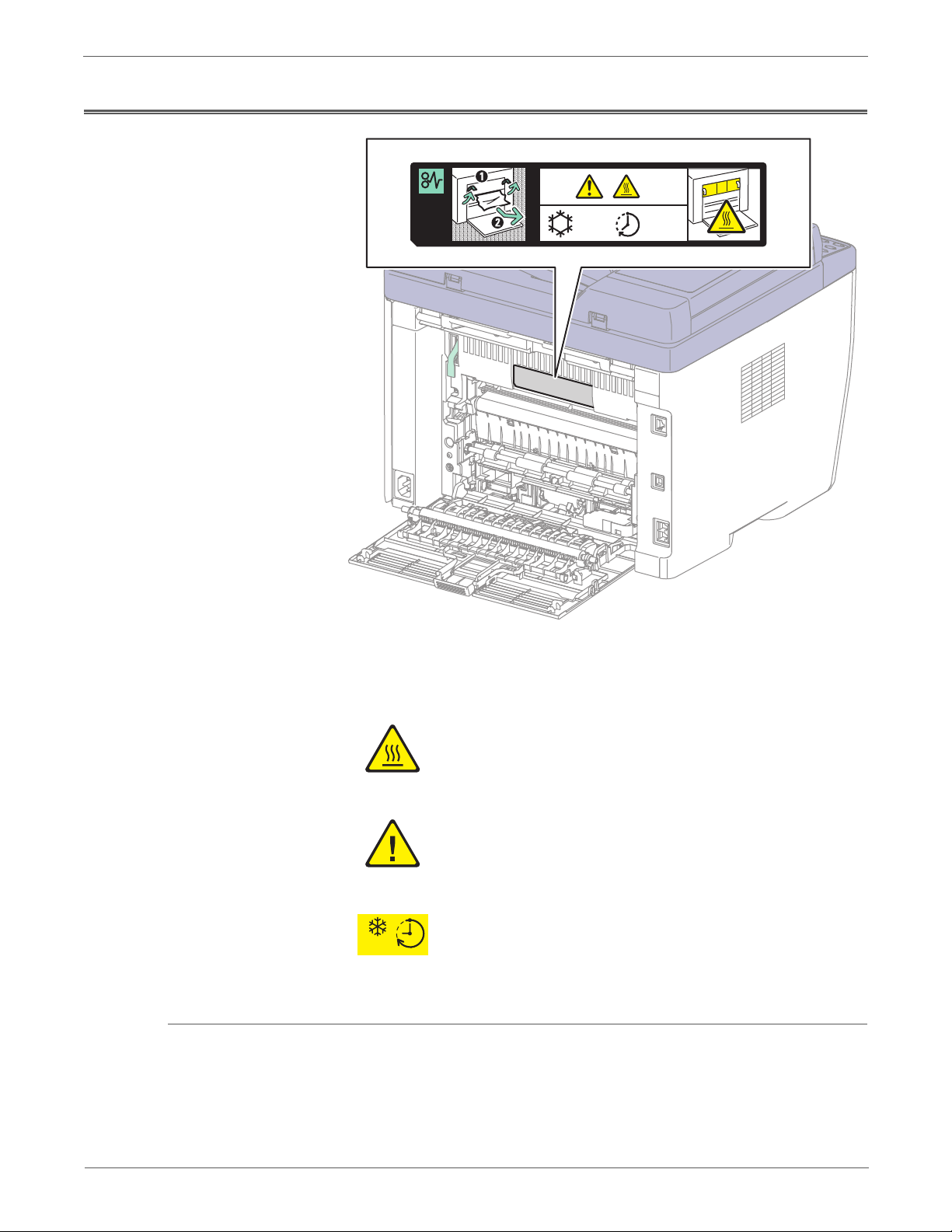
Symbols Marked on the Product
s6015-043
155°C
311° F
00:40
00
Product Terms
Hot surface on or in the printer. Use caution to avoid personal
injury.
Use caution (or draws attention to a particular component).
Refer to the manua l(s) for information.
It may take 40 minutes for the Fuser to cool down.
00:40
Caution: A personal injury hazard exists that may not be apparent. For example, a
panel may cover the hazardous area.
Danger: A personal injury hazard exists in the area where you see the sign.
Phaser 6000/6010 and WC 6015 MFP Xerox Internal Use Only xv
Page 16

Power Safety Precautions
Warning
Power Source
For 115 VAC printers, do not apply more than 127 volts RMS between the supply
conductors or between either supply conductor and ground. For 230 VAC printers,
do not apply more than 254 volts RMS between the supply conductors or between
either supply conductor and ground. Use only the specified power cord and
connector. This manual assumes that the reader is a qualified service technician.
Plug the three-wire power cord (with grounding prong) into a grounded AC outlet
only. If necessary, contact a licensed electrician to install a properly grounded
outlet. If the product loses its ground connection, contact with conductive parts
may cause an electrical shock. A protective ground connection by way of the
grounding conductor in the power cord is essential for safe operation.
Disconnecting Power
Turning the power Off using the power switch does not completely de-energize
the printer. You must also disconnect the Power Cord from the printer’s
Alternating Current (AC) inlet. Disconnect the Power Cord by pulling the plug,
not the cord.
Disconnect the Power Cord in the following cases:
• if the power cord or plug is frayed or otherwise damaged,
• if any liquid or foreign material is spilled into the product,
• if the printer is exposed to any excess moisture,
• if the printer is dropped or damaged,
• if you suspect that the product needs servicing or repair,
• whenever you clean the product.
xvi Xerox Internal Use Only Phaser 6000/6010 and WC 6015 MFP
Page 17

Electrostatic Discharge (ESD) Precautions
Some semiconductor components, and the respective sub-assemblies that contain
them, are vulnerable to damage by Electrostatic Discharge (ESD). These
components include Integrated Circuits (ICs), Large-Scale Integrated circuits
(LSIs), field-effect transistors, and other semiconductor chip components. The
following techniques will reduce the occurrence of component damage caused by
static electricity.
Be sure the power is Off and observe these other safety precautions.
• Immediately before handling any semiconductor component assemblies,
drain the electrostatic charge from your body. This can be accomplished by
touching an earth ground source or by wearing a wrist strap device connected
to an earth ground source. Wearing a wrist strap will also prevent
accumulation of additional bodily static charges. Be sure to remove the wrist
strap before applying power to the unit under test to avoid potential shock.
• After removing a static sensitive assembly from its anti-static bag, place it on
a grounded conductive surface. If the anti-static bag is conductive, you may
ground the bag and use it as a conductive surface.
• Do not use freon-propelled chemicals. These can generate electrical charges
sufficient to damage some devices.
• Do not remove a replacement component or electrical sub-assembly from its
protective package until you are ready to install it.
• Immediately before removing the protective material from the leads of a
replacement device, touch the protective material to the chassis or circuit
assembly into which the device will be installed.
• Minimize body motions when handling unpacked replacement devices.
Motion such as your clothes brushing together, or lifting a foot from a
carpeted floor can generate enough static electricity to damage an electrostatically sensitive device.
• Handle ICs and Erasable Programmable Read-Only Memories (EPROM’s)
carefully to avoid bending pins.
• Pay attention to the direction of parts when mounting or inserting them on
Circuit Boards.
Phaser 6000/6010 and WC 6015 MFP Xerox Internal Use Only xvii
Page 18

Service Safety Summary
General Guidelines
For qualified service personnel only: Refer also to the preceding “Power Safety
Precautions” on page xvi.
Avoid servicing alone: Do not perform internal service or adjustment of this
product unless another person capable of rendering first aid or resuscitation is
present.
Use care when servicing with power: Dangerous voltages may exist at several
points in this product. To avoid personal injury, do not touch exposed connections
and components while power is On. Disconnect power before removing the power
supply shield or replacing components.
Do not wear jewelry: Remove jewelry prior to servicing. Rings, necklaces and
other metallic objects could come into contact with dangerous voltages and
currents.
Warning Labels
Read and obey all posted warning labels. Throughout the printer, warning labels
are displayed on potentially dangerous components. As you service the printer,
check to make certain that all warning labels remain in place.
Safety Interlock
Make sure all covers are in place and the Interlock Switch is functioning correctly
after you have completed a printer service call. If you bypass an Interlock Switch
during a service call, use extreme caution when working on or around the printer.
xviii Xerox Internal Use Only Phaser 6000/6010 and WC 6015 MFP
Page 19
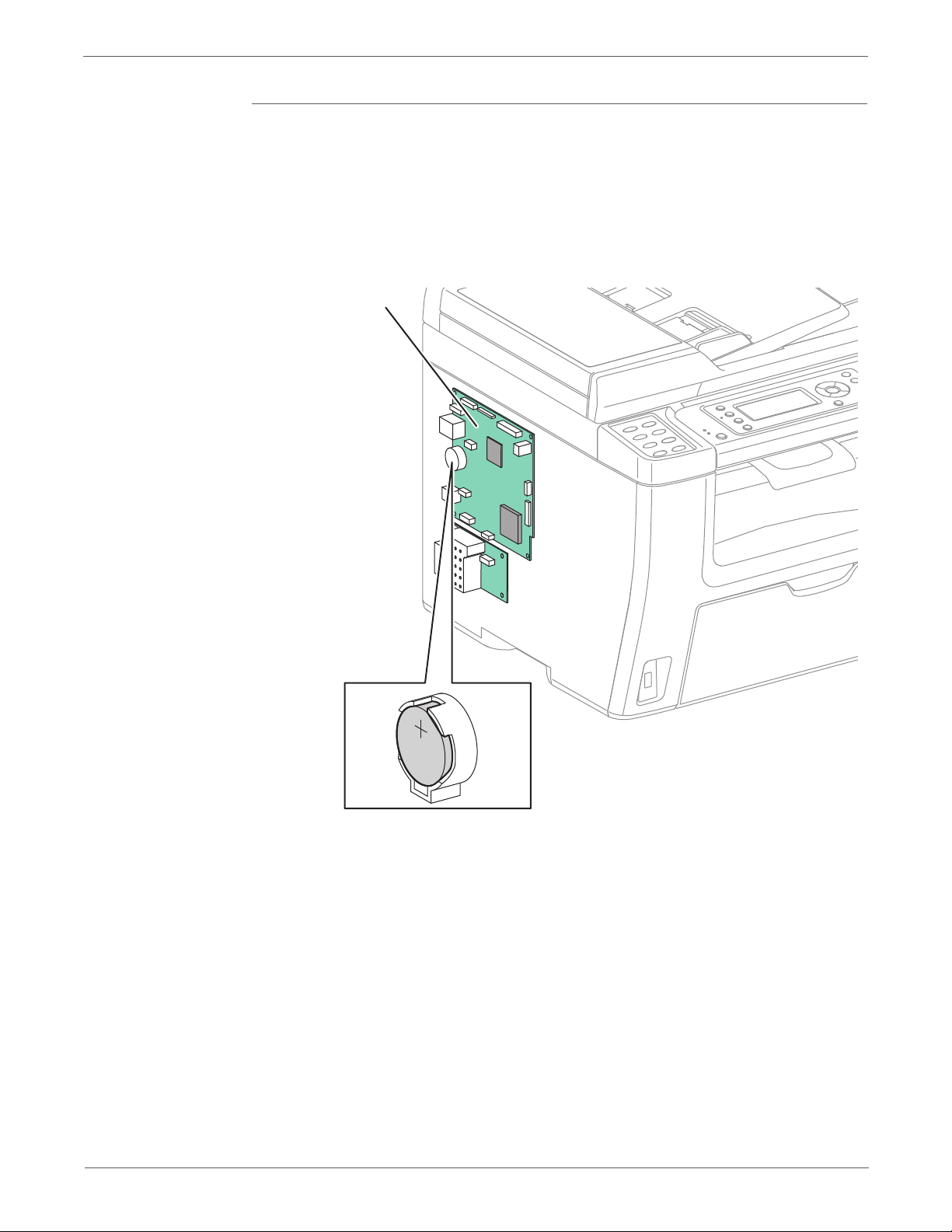
Battery
Warning
IP Board
s6015-042
A Lithium battery is used on the Image Processor Board.
There is a danger of a new battery exploding if it is incorrectly installed.
Replace the battery with the same or equivalent type. Dispose the battery
according to the manufacture’s instruction.
Phaser 6000/6010 and WC 6015 MFP Xerox Internal Use Only xix
Page 20

Servicing Electrical Components
Warning
Warning
Warning
Before starting any service procedure, switch the printer power Off and unplug the
power cord from the wall outlet. If you must service the printer with power applied,
be aware of the potential for electrical shock.
Do not touch any electrical component unless you are instructed to do so by a
service procedure.
Servicing Mechanical Components
When servicing mechanical components within the printer, manually rotate the
Drive Assemblies, Rollers, and Gears.
Do not try to manually rotate or manually stop the drive assemblies while any
motor is running.
Servicing Fuser Components
This printer uses heat to fuse the image to the media. During operation, the
Fuser is very hot. Allow at least 5 minutes for the Fuser to cool before you
attempt to service the Fuser or adjacent components.
xx Xerox Internal Use Only Phaser 6000/6010 and WC 6015 MFP
Page 21

Regulatory
United States (FCC Regulations)
Xerox has tested this product to electromagnetic emission and immunity
standards. These standards are designed to mitigate interference caused or
received by this product in a typical office environment.
This equipment has been tested and found to comply with the limits for a Class B
digital device, pursuant to Part 15 of the Federal Communications Commission
(FCC) Rules. These limits are designed to provide reasonable protection against
harmful interference in a residential installation. This equipment generates, uses,
and can radiate radio frequency energy. If it is not installed and used in
accordance with these instructions, it may cause harmful interference to radio
communications. However, there is no guarantee that interference will not occur in
a particular installation. If this equipment does cause harmful interference to radio
or television reception, which can be determined by turning the equipment Off
and On, the user is encouraged to try to correct the interference by one or more of
the following measures:
• Reorient or relocate the receiver (device being interfered with).
• Increase the separation between the printer and the receiver.
• Connect the equipment into an outlet on a circuit different from that which
• Consult the dealer or an experienced radio/television technician for help.
Any changes or modifications not expressly approved by Xerox could void the
user's authority to operate the equipment. To ensure compliance with Part 15 of
the FCC rules, use shielded interface cables.
Canada (Regulations)
This Class B digital apparatus complies with Canadian ICES-003.
Cet appareil numérique de la classe B est conforme à la norme NMB-003 du
Canada.
the receiver is connected.
Phaser 6000/6010 and WC 6015 MFP Xerox Internal Use Only xxi
Page 22

European Union
The CE mark applied to this product symbolizes Xerox’s Declaration of Conformity
with the following applicable Directives of the European Union as of the dates
indicated:
December 12, 2006: Low Voltage Directive 2006/95/EC
December 15, 2004: Electromagnetic Compatibility Directive 2004/108/EC
March 9, 1999: Radio Equipment & Telecommunications Terminal Equipment
Directive 1999/5/EC
This product, if used properly in accordance with the user's instructions, is neither
dangerous for the consumer nor for the environment.
To ensure compliance with European Union regulations, use shielded interface
cables.
A signed copy of the Declaration of Conformity for this product can be obtained
from Xerox.
xxii Xerox Internal Use Only Phaser 6000/6010 and WC 6015 MFP
Page 23

General Information
In the chapter....
• Printer Overview
• Printer Configurations
• Parts of the Printer
• Consumables
•Specifications
Chapter
1
Page 24

General Information
Printer Overview
Technical Support Information
The Xerox Phaser Phaser 6000/6010 and WC 6015 MFPs have a LED xerography
color tandem print engine. These printers offers print speeds of 10-15 pages-perminute (ppm), and resolutions up to 600 x 600 dots-per-inch (dpi).
The WorkCentre 6015 MFP is a multifunction printer (MFP) that combines a
600 dpi scanner with the color LED printer to provide print, copy, and scan
functionality. In addition to USB2.0, the WorkCentre 6015NI Color MFP provides
10/100 Base-T, wireless capability, and Fax functionality.
The Xerox Service Manual is the primary document used for repairing,
maintaining, and troubleshooting the printers. To ensure complete understanding
of this product, participation in Xerox Service Training is strongly recommended.
For updates to the Service Manual, Service Bulletins, knowledge base, etc., go to:
• Xerox Global Service Net: https://www.xrxgsn.com/secure/main.pl
• Service Partners: http://www.office.xerox.com/partners
For further technical support, contact your assigned Xerox Technical Support for
this product.
1-2 Xerox Internal Use Only Phaser 6000/6010 and WC 6015 MFP
Page 25

Printer Configurations
General Information
The following tables list the configurations of the Phaser 6000/6010 Printers and
the WorkCentre 6015 MFPs.
Phaser 6000/6010 Printer Configurations
Fea tures Phaser 6000B Phaser 6010N
Processor Speed 192 MHz 384 MHz
Memory 64 MB 128 MB
Print Speed (A4) 10 Color/12 BW 12 Color/15 BW
Resolution 1200 x 1200 dpi 1200 x 1200 dpi
USB 2.0 Support Standard Standard
Ethernet Interface
10/100 Base-TX
Manual Feed Slot None Standard
Main Paper Tray Standard Standard
WorkCentre 6015 MFP Configurations
Fea tures
Processor Speed 295 MHz 295 MHz 295 MHz
Memory 128MB 128 MB 128 MB
Print Speed (A4) 12 Color/15 BW 12 Color / 15 BW12 Color / 15
Resolution 1200 x 1200
USB 2.0 Support Standard Standard Standard
Ethernet Interface
10/100 Base-TX
None Standard
WorkCentre
6015B Color
MFP
dpi
None Standard Standard
WorkCentre
6015N Color
MFP
1200 x 1200
dpi
WorkCentre
6015NI Color
MFP
BW
1200 x 1200
dpi
Wireless Interface None None Standard
Fax None Standard Standard
Automatic Document
Feeder
Manual Feed Slot Standard Standard Standard
Main Paper Tray Standard Standard Standard
Phaser 6000/6010 and WC 6015 MFP Xerox Internal Use Only 1-3
None Standard Standard
Page 26
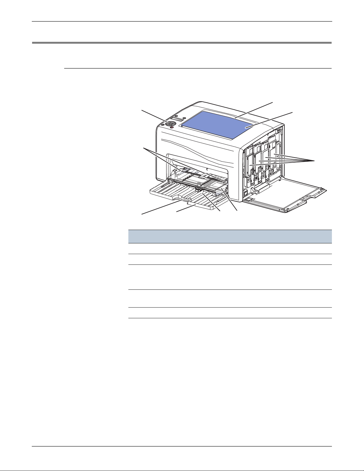
General Information
s6000-171
1
4
2
3
9
7
5
6
8
Parts of the Printer
Front and Side View
Phaser 6000/6010
Item Description Item Description
1Output Tray 6Front Cover
2 Output Tray Extension 7 Front Cover Handle
3 Toner Cartridges 8 Bypass Tray Feeder Guides
(6010N and WorkCentre 6015
MFP only)
4 Bypass Tray (6010N an
WorkCentre 6015 MFP only)
5 Main Paper Tray
9 Control Panel
1-4 Xerox Internal Use Only Phaser 6000/6010 and WC 6015 MFP
Page 27
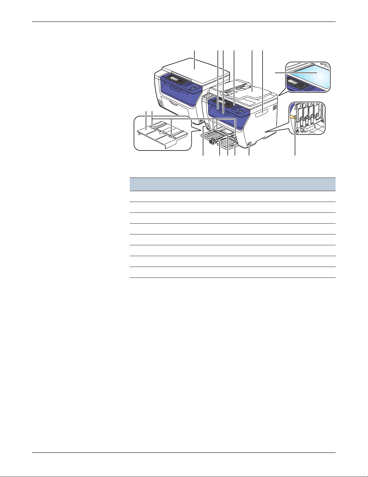
WorkCentre 6015 MFP
12
64 5 73 8
9
1114 1213 1015
s6015-044
Item Description Item Description
General Information
1Bypass Tray 9Document Glass
2 Feeder Guides 10 LED Cleaning Rod
3Platen Cover 11Power Switch
4 Output Tray 12 Front Cover
5 Output Tray Extension 13 Main Paper Tray
6 Control Panel 14 Main Tray Extension
7 ADF Input Tray 15 USB Connector
8 Toner Door Handle
Phaser 6000/6010 and WC 6015 MFP Xerox Internal Use Only 1-5
Page 28
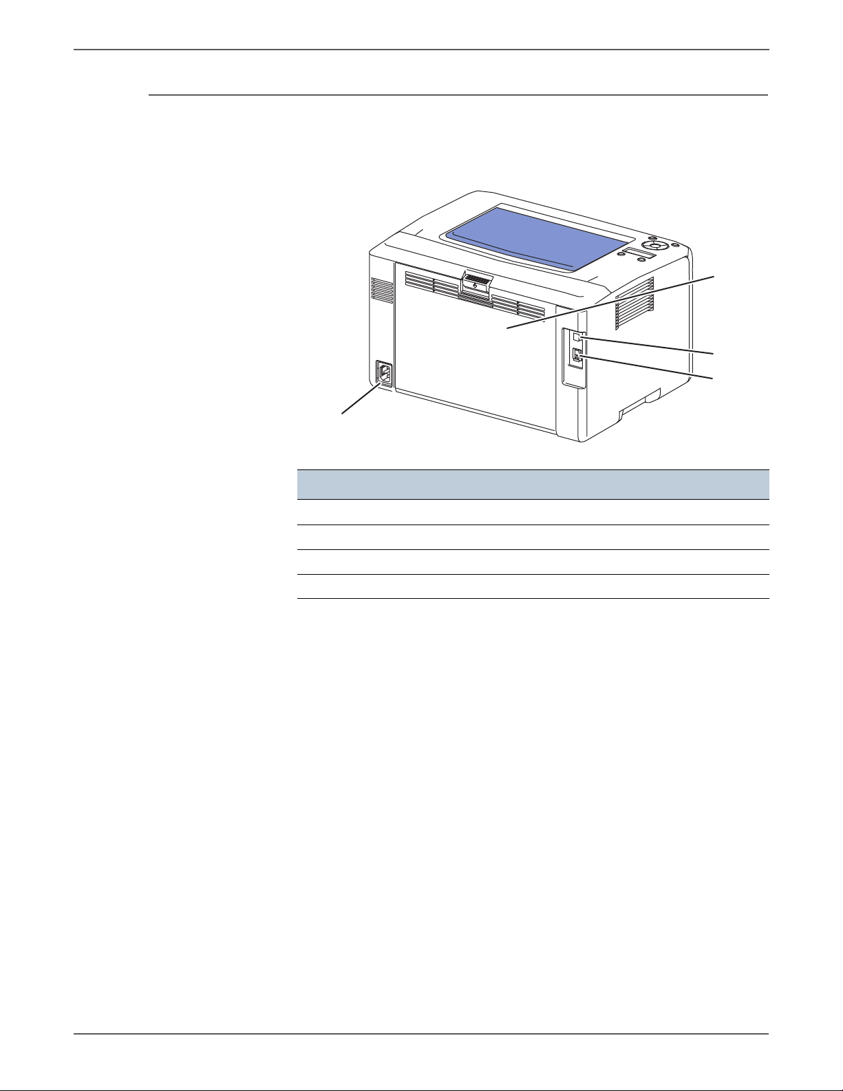
General Information
s6000-172
1
2
3
4
Rear View
Phaser 6000/6010 Printer
Item Description
1Rear Door
2USB Port
3 Network Port (6010N only)
4Power Receptacle
1-6 Xerox Internal Use Only Phaser 6000/6010 and WC 6015 MFP
Page 29
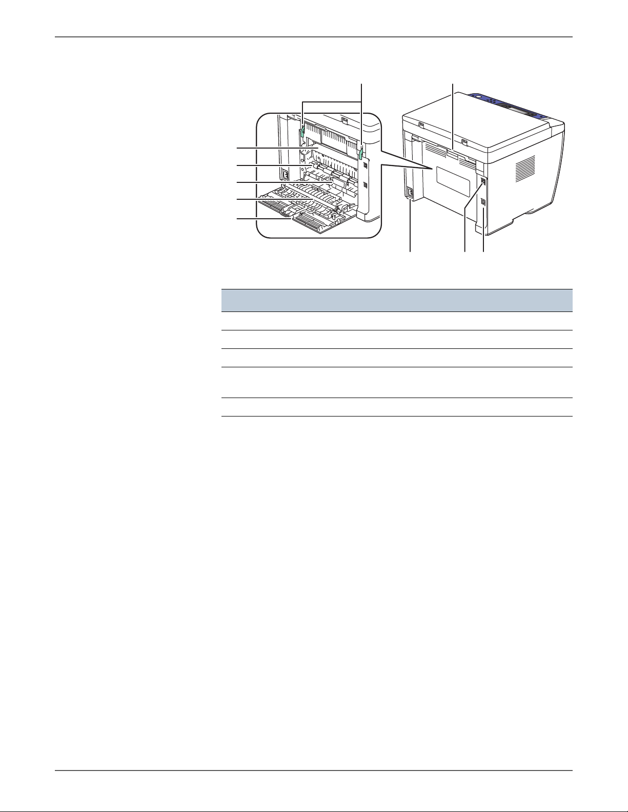
WorkCentre 6015 MFP
5
67
4
3
2
1
10 89
s6015-045
Item Description Item Description
1 Rear Door 6 Fuser Levers
General Information
2 Transfer Roller 7 Rear Door Latch
3 Separator Pad Assembly 8 USB Port
4 Registration Pinch Roller 9 Ethernet Port (6015N/NI
5 Transfer Belt 10 Power Receptacle
models only)
Phaser 6000/6010 and WC 6015 MFP Xerox Internal Use Only 1-7
Page 30
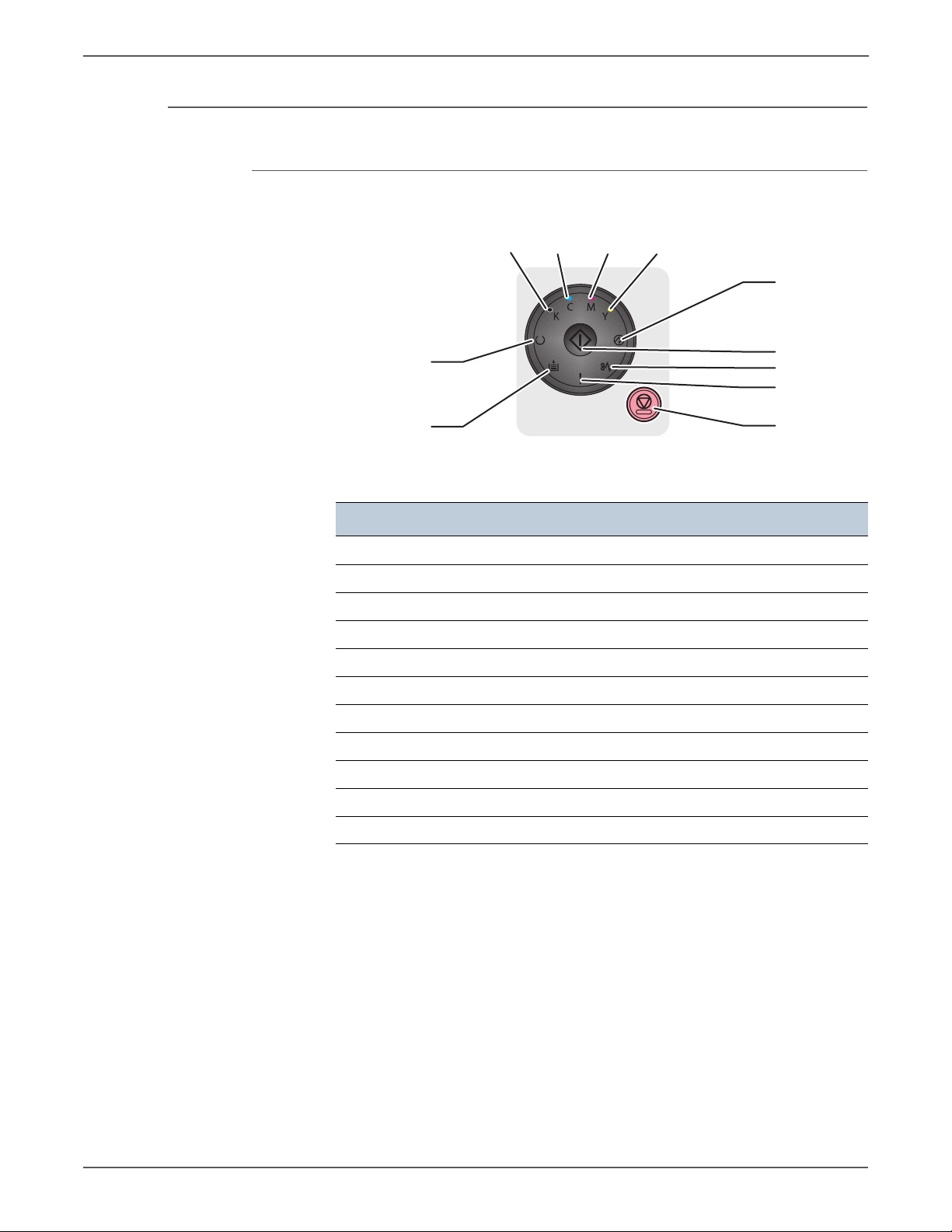
General Information
1
2
11
10
9
7
8
3456
s6000-138
Control Panel
Phaser 6000B Control Panel
Item Fea ture
1 Load Paper LED
2 Ready/Data LED
3 Black Toner LED
4 Cyan Toner LED
5 Magenta Toner LED
6 Yellow Toner LED
7 Power Saver LED
8 OK LED
9 Jam LED
10 Error LED
11 Cancel button
For more information on the 6000B Control Panel, see “Phaser 6000B Errors” on
page 3-18.
1-8 Xerox Internal Use Only Phaser 6000/6010 and WC 6015 MFP
Page 31

Phaser 6010N Control Panel
Ready
1
10
9
8
7
6
5
2
3
4
s6000-139
Item Fea ture Description
1 Online LED Displays the online printer status.
General Information
2Back Button Move back to upper menu.
3 LCD Indicates printer status, warnings, and error
messages.
4Menu Button When pressed the top menu level is displayed on
the LCD.
5Energy Saver
Button
When illuminated, indicates the printer is in Power
Saver Mode 1.
Press to change to Ready to Print from Energy Saver
mode.
6 Toner Status Indicates the amount of toner left in each Toner
Cartridge.
7Arrow Buttons Use to navigate the menu.
8OK Button Enter current setting/confirm current selection.
9Cancel Button Cancels print job.
10 Error LED When illuminated, indicates a printer error.
Phaser 6000/6010 and WC 6015 MFP Xerox Internal Use Only 1-9
Page 32

General Information
1 32 4
5
6
7
8
91012 1113
s6015-064
WorkCentre 6015B Color MFP Control Panel
Item Feature (number) Description
1Copy
Scan
Print
2 Navigation/Menu
select buttons (5)
Move to the top of the Copy menu.
Move to the top of the Scan menu.
Move to the top of the Print menu.
Scroll up, down, forward, and back through the
menus.
Use the OK button to enter current setting/confirm
current selection.
3System Switches the display to the System menus.
4 Alpha Numeric
Input and delete numbers.
Keypad (11)
5 Wake Up / Energy
Saver button
When illuminated, indicates the printer is in Power
Saver Mode 1.
Press to move to Ready to Print from Energy Saver
mode.
6 Clear All button When the user is making changes to a service
(Copy, Scan, Print, or Fax), pressing the Clear All
button restores the previous settings and returns
the menu to the top level of the service.
7Stop button Stops the current job.
8Start button Starts the current job.
9 Data LED
Indicates the status of the printer – power and
ready-to-print.
Error LED
When illuminated, indicates a printer error such as a
paper jam.
10 Back button Move back to previous screen.
11 LCD Indicates printer status, warnings, and error
messages.
12 Color Mode
Switch color mode (Color/B&W) for Copy and Scan.
Button
13 B/W, Color
indicator LEDs
Upper LED indicates Black and White mode. Lower
LED indicates Color mode.
1-10 Xerox Internal Use Only Phaser 6000/6010 and WC 6015 MFP
Page 33

WorkCentre 6015N/NI Color MFP Control Panel
2 7 84 53 61
9
10
11
12
13141517 1618
s6015-046
Item Feature (number) Description
General Information
1 Direct Address
Keys(8)
Press to quickly dial Fax number s that are
registered in the Phone Book. The first four entries
are assigned to the keys.
2
■ Copy
■ Scan
■ Print
■ Fax
3 Navigation/Menu
select buttons (5)
Use these buttons to move to the top of each
menu.
Scroll up, down, forward, and back through the
menus. Use the OK button to select a current
setting/confirm current selection.
4Job Status button Press to check active job status.
5System button Switches the display to the System menus.
6 Alpha Numeric
Input and delete letters and numbers.
Keypad (13)
7 Redial/Pause
button
Press the button to recall the last Fax number used
or to insert pauses in Fax numbers.
8Speed Dial button Press to access directories of group or individual Fax
telephone numbers.
9 Wake Up / Energy
Saver button
When illuminated, indicates the printer is in Power
Saver Mode 1.
Press to move to Ready to Print from Energy Saver
mode.
10 Clear All button When the user is making changes to a function
(Copy, Scan, Print, or Fax), pressing the Clear All
button restores the previous settings and returns
the menu to the top level of that function.
11 Stop button Stops the current job.
12 Start button Starts the current job.
13 Data LED
Indicates the status of the printer – power and
ready-to-print.
Error LED
14 Address Book
button
15 Back button Move back to previous screen.
When illuminated, indicates a printer error.
Move to Address Book menu for Fax and E-mail.
Phaser 6000/6010 and WC 6015 MFP Xerox Internal Use Only 1-11
Page 34

General Information
Item Feature (number) Description
16 LCD Indicates printer status, warnings, and error
messages.
17 Color Mode
Button
18 Black and
White/Color
indicator LEDs
Switch color mode (Color/B&W) for Copy and Scan.
Upper LED indicates Black and White mode. Lower
LED indicates Color mode.
1-12 Xerox Internal Use Only Phaser 6000/6010 and WC 6015 MFP
Page 35

Consumables
s6000-020
Toner
Cartridge (K)
Toner
Cartridge (C)
Toner
Cartridge (M)
Toner
Cartridge (Y)
General Information
The Toner Cartridges are the only consumables. The Toner Cartridge CRUM
(Customer Replaceable Unit Meter) records toner usage data.
Phaser 6000:
When a Toner Cartridge reaches the end of estimated cartridge life, the status is
indicated by the Error LED on the Control Panel.
Phaser 6010 and WorkCentre 6015 MFP:
When a Toner Cartridge reaches the end of estimated cartridge life, the status is
indicated on the LCD.
Toner Cartridge Capacity
Approximate Print Life
Black Starter Capacity 500 pages
Standard Capacity 2000 pages
Yellow, Magenta,
and Cyan
Starter Capacity 500 pages
Standard Capacity 1000 pages
a. Declared cartridge yield in accordance with ISO/IEC 19798 and
ISO/IEC 24712
a
Phaser 6000/6010 and WC 6015 MFP Xerox Internal Use Only 1-13
Page 36

General Information
s6015-063
Toner Cartridges (C, M, Y, K)
1-14 Xerox Internal Use Only Phaser 6000/6010 and WC 6015 MFP
Page 37

Specifications
Printer Specifications
General Information
Printer Specifications
Characteristic Specifications
Printing Technology LED xerography
Printer Life 5 years from the start of use,
or 30 kPV or more in A4 SEF, or total number of
platen scan and ADF scan reaches 40k or more.
Average Monthly Print Volume 6000B: 250 PV/month
6010N: 350 PV/month
WorkCentre 6015 MFP: 350 to 450 PV/month
Maximum Monthly Duty Cycle 30,000 kPV/month
Monthly Scan Volume 350
Warm-Up Time Less than 25 seconds
Power Saver Mode 1 The default setting is 60 minutes. Use the
Printer Settings Utility to change the default
setting from 5 to 60 minutes.
Power Saver Mode 2 The printer enters Power Saver Mode 2 after the
specified time. The default setting is 1 minute,
and can be set from 1 minute to 60 minutes.
Resolution 1200 x 1200 dpi
Main Paper Tray (150 Sheets) Standard
Bypass Tray (15 Sheets) Standard on Phaser 6010N and WorkCentre
6015 MFPs
Memory (Phaser 6000B) 64 MB
Memory (Phaser 6010N and
128 MB
WorkCentre 6015 MFPs)
External Interfaces
Phaser 6000B
USB 2.0
■ Connector Type: One Type B
■ Protocol: Hi-speed USB 2.0 compatible
Phaser 6010N
USB 2.0 ■ Connector Type: One Type B
■ Protocol: Hi-speed USB 2.0 compatible
Ethernet
■ Connector Type: One RJ-45 connector
■ 10 BASE-T/100 BASE-TX compatible
Phaser 6000/6010 and WC 6015 MFP Xerox Internal Use Only 1-15
Page 38

General Information
Printer Specifications (Continued)
Characteristic Specifications
WorkCentre 6015B Color
MFP
USB 2.0 ■ Connector Type: One Type A, One Type B
■ Protocol: Hi-speed USB 2.0 compatible
WorkCentre 6015N Color
MFP
USB 2.0 ■ Connector Type: One Type A, One Type B
■ Protocol: Hi-speed USB 2.0 compatible
Ethernet
■ Connector Type: One RJ-45 connector
■ 10 BASE-T/100 BASE-TX compatible
WorkCentre 6015NI Color
MFP
USB 2.0 ■ Connector Type: One Type A, One Type B
■ Protocol: Hi-speed USB 2.0 compatible
Ethernet
Wireless
■ Connector Type: One RJ-45 connector
■ 10 BASE-T/100 BASE-TX compatible
■ Compliant Standard: IEEE802.11b/g
■ Security Protocol: WEP (64/128bits), WPA-PSK
(TKIP, AES), WPA-2PSK (AES)
■ Certifications: Wi-Fi, WPA2.0
■ Wi-Fi Protected Setup (WPS): Push Button
Configuration (PBC), Personal Identification
Number (PIN)
Operating System
Phaser 6000/6010
Mac Mac OS X 10.5 or later
Windows Windows 7 (32/64 bit), Windows XP (32/64 bit),
Vista (32/64 bit), 2003 Server (32/64 bit),
2008 Server (32/64 bit)
Linux Supported
WorkCentre 6015 MFPs
Mac Mac OS 10.4.11/10.5.8 or later, and 10.6.X
(Power PC, Intel X86 Processors)
Windows Windows 7 (32/64 bit), Windows XP (32/64 bit),
Vista (32/64 bit), 2003 Server (32/64 bit),
2008 Server (32/64 bit), 2008R2 (64 bit)
Linux Supported
Memory Specifications Memory
Phaser 6000B ■ Main Memory: 64 MB
■ Flash ROM: 2 MB
Phaser 6010N
■ Main Memory: 128 MB
■ Flash ROM: 8 MB
1-16 Xerox Internal Use Only Phaser 6000/6010 and WC 6015 MFP
Page 39

Printer Specifications (Continued)
Characteristic Specifications
WorkCentre 6015B Color MFP ■ Main Memory: 128 MB
■ Flash ROM: 16 MB
General Information
WorkCentre 6015N Color MFP
WorkCentre 6015NI Color MFP
Copy Specifications
Copy Specifications
■ Main Memory: 128 MB
■ Flash ROM: 16 MB
■ Memory for Fax: 2 MB
Characteristic Specifications
Auto Exposure On/Off
Collate (max pages) 50 Color / Black and White pages max.
Color Balance 5 Levels (RGB)
Continuous Copy Speed of
2.5 Color / 12.8 Black and White cpm
Multiple-sheet Document in
ADF Mode (cpm)
Grey Balance Supported
Image Rotation The image can be rotated by 180° before
printing.
Lighten/Darken 5 Levels
Margin Adjustment Top/Bottom, Left/Right, and middle.
Multiple Up (N to 1) Continuous 2, 4, 8, or 32 pages can be printed
on one sheet of paper.
Number of Copies 1-99
Or i g i n a l Typ e Text, P h o t o , Te x t/P h o t o
Poster 2x3, 3x3, 4x4
Sharpness 5 Levels
Auto Fit On, Off
Cloning On, Off
Watermarks Documents can be printed with pre-registered
watermarks.
Copy Mode
Color (default) The following modes are available
■ Te x t / P h o to ( d efaul t )
■ Photo
■ Te x t
Phaser 6000/6010 and WC 6015 MFP Xerox Internal Use Only 1-17
Page 40

General Information
Copy Specifications (Continued)
Characteristic Specifications
Black and White The following modes are available
■ Te x t / P h o to ( d efaul t )
■ Photo
■ Te x t
Image Quality
Resolution
WorkCentre 6015B Color MFP
WorkCentre 6015N/NI Color
MFP
Auto Exposure Off, Normal, Higher (1, 2)
Color Balance 4 colors, 3 densities, 5 levels (RGB)
Color Saturation 3 levels
Density Adjustment 5 levels
Sharpness 5 levels
Magnification
Fixed 200%, 141%, 122%, 100%, 81%, 70%, 50%
Variable 25% to 400% in 1% increments
Scanning Specifications
Scanning Specifications
Characteristic Specifications
Platen
600 x 600
600 x 600
ADF
Not applicable
600 x 300
Scan Mode
■ Platen Mode: Scan document using the
document glass.
■ Constant Velocity Transport (CVT) Mode:
Scan document via the ADF.
Local (USB) Scanning
Scan Interface TWAIN, WIA 2.0
Resolution Up to 4800 dpi
Network Scanning
Scan Interface TWAIN, WIA 2.0
Color Mode Color, Black & White
Original Type Text, photo, mixed
1-18 Xerox Internal Use Only Phaser 6000/6010 and WC 6015 MFP
Page 41

General Information
Scanning Specifications (Continued)
Characteristic Specifications
Lighten/Darken 5 levels
Sharpness 3 levels
Image Rotation 90, 180, 270 degrees
Auto Exposure Off, Normal, Higher(1), Higher(2)
File Format TIFF, JPEG, PDF
Resolution
■ TWAIN: 75 x 75 dpi up to 4800 x 4800 dpi
■ WIA: 75/100/150/200/300/400/600 dpi
■ Resolutions other than the following are
achieved by driver's resolution conversion.
200 x 200 dpi
300 x 300 dpi
600 x 600 dpi
1200 x 1200 dpi
File Format JPG, TIFF, PDF
Scan to “Desktop” via SMB Up to 6 SMB servers
Scan to FTP Up to 6 FTP servers
Scan to E-mail Supported
E-mail Address Book Up to 100 E-mail Addresses, and up to 10
E-mail Groups.
Addresses are stored in device memory. Each
E-mail Group may have up to 10 addresses
associated with it.
Black and
Scan Performance Document
USB Scan to PC (via Express
Scan Manager)
Platen, 300
dpi, 24-bit
White
Color
11 seconds 9 seconds
color, letter
Network Scan to PC via SMB Platen, 150
9 seconds 9 seconds
dpi, mixed,
letter size
USB Scan to PC (Twain/WIA) Platen, 300
11 seconds 9 seconds
dpi, 24-bit
color letter
Maximum Scanning Area
Document Glass 215.9 mm x 297 mm (8.5” x 11.7”)
ADF
215.9 mm x 355.6 mm (8.5” x 14”)
Scanning Halftone Level
Output from the CCD has the
following halftone levels.
B/W: 1 bit for Line art and 8 bit for grayscale.
Color: 24 bit.
Phaser 6000/6010 and WC 6015 MFP Xerox Internal Use Only 1-19
Page 42

General Information
Scanning Specifications (Continued)
Characteristic Specifications
Platen
Document Setting Reference
Left rear corner as viewed from printer front.
Position
Document Glass Size 220 mm x 300 mm (8.66 in. x 11.8 in) (Flat
glass area)
ADF
Resolution (Line Density in Fast
1200 dots/25.4 mm (1200 dots/1 inch)
Scan Direction)
Document Thickness
60 g/m
2
to 105 g/m
Capacity 15 sheets (plain paper)
Fax Specifications (WorkCentre 6015N/NI Color MFP)
Fax Specifications
Characteristic Specifications
Communication Mode Priority 1: ITU-T Super G3
Priority 2: ITU-T G3 ECM
Priority 3: ITU-T G3
2
Direct Fax Supported
Facsimile Communication
Not supported
Network (FAX NET)
Fax Send/Receive Buffer 2 MB
Supported Network PSTN, PBX
NOTE The printer can not be connected to an ISDN
network.
Supported Protocols ■ V. 34 (Max.33.6 kbps)
■ V. 17 (14.4/12/9.6/7.2 kbps)
■ V. 29 (9.6/7.2 kbps)
■ V. 27ter (4.8/2.4 kbps)
Transfer If the machine cannot print received FAX data
because of printer trouble, or when the user
specifies transfer of received data, received
data is automatically sent to a pre-registered
machine.
Settings: OFF, Forward only, or Print & Forward.
Walk-up Fax
Incoming Call Control Telephone Mode, Auto Receive, iFax, Tel/Fax,
Ans/Fax, DRPD
Color Fax Not supported
Resolution Standard, Fine, Super Fine, and Ultra Fine
1-20 Xerox Internal Use Only Phaser 6000/6010 and WC 6015 MFP
Page 43

General Information
Fax Specifications (Continued)
Characteristic Specifications
Compression Method B/W: 1bit, JBIG, MMR, MR, MH encoding
Color: Not supported
DM Protection Rejects junk Fax
Polling Receive Auto, Manual
Auto Reduction Rec On, Off, and Auto
Delayed Start Up to 23 hours and 59 minutes
Broadcast Sending Sequential only
Fax Cov er Page Suppor ted
On Hook Supported
Remote Receive Supported
Fax A ddr ess Book Suppo rted
Lan Fax
Driver GDI Drivers
Resolution Normal (200 x 100), Fine (200 x 200),
Superfine (400 x 400)
Color Not supported
Delayed Start Up to 24 hours
Broadcast Sending Up to 30 destinations
Zoom Same as printer driver.
Auto RE (auto fit) Same as printer driver.
Rotation Same as printer driver.
N-up Same as printer driver.
Watermark Same as printer driver.
Phone Book Up to 500 Speed Dial Numbers and up to 500
Group Dial. Local phone book stored on PC.
Secure Receive Supported
Phaser 6000/6010 and WC 6015 MFP Xerox Internal Use Only 1-21
Page 44

General Information
s6015-033
CMOS Image
Sensor
111111
100001
101111
Scanner
Scanning
LED
Original
Original
Black becomes 0,
white 1 creating...
Digital data
Image
Control Circuit
Digital signal
Modem
DA
Conversion
(Modulation)
A/D Conversion Unit
A/D Conversion Unit
NCU
NCU
Analog signal
Sending FAX
Telephone line
Receiving FAX
Control Circuit
Modem
AD
conversion
(demodulation)
Printer
Digital signal
Printing
Print
1-22 Xerox Internal Use Only Phaser 6000/6010 and WC 6015 MFP
Page 45

Environmental Specifications
Environmental Specifications
Characteristic Specifications
Temperature and Humidity
Operating 10° to 32° C (50° to 90° F) at 15% to 85%
Storage (Packaged) -20° to 0° C (-4° to 32° F) at 5% to 15% RH
Altitude
Operating 0 to 3,100 meters (10,170 feet)
Storage (Packaged) 0 to 15,000 meters (49,212 feet)
Acoustic Noise Level
General Information
RH
to
35 to 40° C (95° to 104° F) at 80% to 90%
RH
Printing
Phaser 6000B
Phaser 6010N
Standby
Printing
WorkCentre 6015B Color MFP
WorkCentre 6015N Color MFP no
ADF
WorkCentre 6015NI Color MFP no
ADF
WorkCentre 6015N Color MFP ADF
in use
WorkCentre 6015NI Color MFP ADF
in use
Standby
WorkCentre 6015 MFP all models
Power Save Mode (all models) Background level
Less than 50.0 dB
Less than 52.0 dB
Less than 25.0 dB
64.3 dB
63.5 dB
63.5 dB
65.0 dB
65.0 dB
43.0 dB
Phaser 6000/6010 and WC 6015 MFP Xerox Internal Use Only 1-23
Page 46

General Information
Electrical Specifications
Electrical Specifications
Characteristic Specifications
Inrush Current
Phaser 6000/6010 Printer
Maximum of 120 A within 10 msec (half cycle)
or less
WorkCentre 6015 MFP
Maximum of 100 A within 10 msec (half cycle)
or less
Power Supply Voltage/Frequency
Line Voltages
a
110-127 VAC ± 10%
220-240 VAC ±10%
Max Current 110 V Engine: < 8 A
220 V Engine: < 5 A
Frequency Range 50/60 Hz ± 3 Hz
Power Consumption
Continuous Color Printing
■ Phaser 6000B
■ Phaser 6010N
■ WorkCentre 6015 MFP
285 W or less
340 W or less
310 W or less
(full option model)
Continuos Black and White
■ Phaser 6000B
■ Phaser 6010N
■ WorkCentre 6015 MFP
285 W or less
340 W or less
350 W or less
(full option model)
Ready Mode
■ Phaser 6000B
■ Phaser 6010N
■ WorkCentre 6015 MFP
65 W or less
69 W or less
65 W or less
(full option model)
Power Saver Mode 1
■ Phaser 6000B
■ Phaser 6010N
■ WorkCentre 6015 MFP
11 W or less
14 W or less
16 W or less
(full option model)
Power Saver Mode 2
■ Phaser 6000B
■ Phaser 6010N
■ WorkCentre 6015 MFP
5 W or less
7 W or less
7 W or less
(full option model)
a. See the Rating label on the machine for the correct voltage, frequency
(hertz), and current for your machine.
1-24 Xerox Internal Use Only Phaser 6000/6010 and WC 6015 MFP
Page 47

Image Specifications
Note
Image Area
Area Definition Specifications
General Information
Edge-to-edge printing is not available.
Operating Modes
Usable Area (maximum paper
size)
Unprintable Area 4.1 mm from edge of all four sides
Printable Area 207.9 x 347.6 mm
Operating Modes
Mode Condition Definition
Running Mode The printer is in an operating status such as
Fusing Kept at the operating temperature.
Exposure
system
Recording
system
Cooling fan The fan operates at high speed.
215.9 mm x 355.6 mm (8.5 inches x 14
inches)
running or recording.
Operating
Operating
Ready Mode The printer is in standby status, ready to
run.
Fusing Kept at standby temperature.
Exposure
system
Recording
system
Cooling fan The fan operates at low speed.
Phaser 6000/6010 and WC 6015 MFP Xerox Internal Use Only 1-25
The system is at Pause.
The system is at Pause.
Page 48

General Information
Operating Modes (Continued)
Mode Condition Definition
Power Saver
Mode 1
Power Saver
Mode 2
Warm Up Time
The printer enters Power Saver Mode 1
when it has not received print data for the
specified time.
Fusing The system is at Pause.
Exposure
system
Recording
system
Cooling fan The system is at Pause.
Fusing The system is at Pause.
Exposure
system
Recording
system
Cooling fan The system is at Pause.
The system is at Pause.
The system is at Pause.
The printer enters Power Saver Mode 2 to
reduce power consumption.
The system is at Pause.
The system is at Pause.
The printer reaches the Ready state within 36 seconds after power on, transition
from Low Power to Ready, and transition from Sleep to Ready.
First Print Output Time
First Print Output Time (FPOT) is defined as the time from when the engine
receives a Start signal, until a single A4 sized page is printed and delivered to the
output tray.
Printer Color Mode
Phaser
6000B
Phaser
6010N,
WorkCentre
6015 MFPs
Ready Mode
Color 29 seconds or
less
Black and
white
Color 27 seconds or
Black and
white
24 seconds or
less
less
22 seconds or
less
FPOT (sec.)
Power Saver
Mode 2
54 seconds or
less
49 seconds or
less
52 seconds or
less
47 seconds or
less
After Power-on
54 seconds or
less
49 seconds or
less
52 seconds or
less
47 seconds or
less
1-26 Xerox Internal Use Only Phaser 6000/6010 and WC 6015 MFP
Page 49

First Copy Output Time (WorkCentre 6015 MFP)
First Copy Output Time (FCOT) is the time required for the printer to deliver the
first sheet of paper after the user presses Start. The following conditions are
applied:
• Printer is in the Ready state
• Document setting: Platen mode
• Magnification Ratio: 100%
• Paper source: Feed from the standard paper tray
• Paper type: Standard paper
•Paper size: A4
• Mode: Standard mode (Factory default)
FCOT:
• Color: 37 seconds or less
• B/W: 24 seconds or less
General Information
Phaser 6000/6010 and WC 6015 MFP Xerox Internal Use Only 1-27
Page 50

General Information
s6000-021
10 cm
(3.9 in.)
30 cm
(12.1 in.)
29.5 cm
(11.6 in.)
33 cm
(13 in.)
Physical Dimensions and Clearances
Phaser 6000/6010 Printer Dimensions and Weight
Print Engine Specification
Height (Output Tray open) 294 mm (11.7 in.)
Width 394 mm (15.5 in.)
Depth (Main Paper Tray open) 429.5 mm (16.9 in.)
Weight Net.: 10.7 kg (23.6 lb.)
1-28 Xerox Internal Use Only Phaser 6000/6010 and WC 6015 MFP
Page 51

General Information
20 cm
(7.9 in.)
10 cm
(3.9 in.)
10 cm
(3.9 in.)
10 cm
(3.9 in.)
11.4 cm
(4.5 in.)
69 cm
(27.2 in.)
93.6 cm
(36.8 in.)
84.8 cm
(33.4 in.)
s6015-047
WorkCentre 6015N/NI Color MFP Printer Dimensions and Weight
Print Engine Specification
Height (Output Tray open) 338 mm (13.31 in.)
Width 410 mm (16.14 in.)
Depth (Main Paper Tray closed) 379 mm (14.92 in.)
Weight (Toner cartridges installed)
WorkCentre 6015B Color MFP
WorkCentre 6015N Color MFP
14.95 kg (32.96 lb.) ± 5%
15.2 kg (33.51 lb.) ± 5%
Phaser 6000/6010 and WC 6015 MFP Xerox Internal Use Only 1-29
Page 52

General Information
Right Hand Side
s6000-184
5 mm Max
s6015-048
1° or 7 mm
1° or 7 mm
Mounting Surface Specifications
The printer must not be tipped or tilted more than 1 degree, front to back and left
to right.
Failure to adhere to the specified mounting specification will void all guarantees of
print-quality and/or performance.
1-30 Xerox Internal Use Only Phaser 6000/6010 and WC 6015 MFP
Page 53

Media and Tray Specifications
Media recommended for use with this printer is known as standard paper. The feed
performance, reliability, and print quality satisfy the specifications.
The following table lists supported media for the Phaser 6000/6010 and WC 6015
MFP printers.
Supported Media Sizes
Size
A4 (210 x 297 mm (8.27 x 11.69 in.)) Y Y
B5 (182 x 257 mm (7.17 x 10.12 in.)) Y Y
A5 (148 x 210 mm (5.83 x 8.27 in.)) Y Y
C5 (162 x 229 mm (6.38 x 9.02 in.)) Y Y
Monarch (98 x 191 mm (3.875 x 7.5 in.)) Y Y
Monarch LEF (191 x 98 mm (7.5 x 3.875 in.)) Y Y
General Information
Main Paper
Tray
Bypass Tray
Envelope #10 (105 x 241 mm (4.125 x 9.5 in.)) Y Y
DL (110 x 220 mm (4.33 x 8.66 in.)) Y Y
DL LEF (220 x 110 mm (8.66 x 4.33 in.)) Y Y
Letter (216 x 279 mm (8.5 x 11 in.)) Y Y
Legal (216 x 356 mm (8.5 x 14 in.)) Y Y
Folio (216 x 330 mm (8.5 x 13 in.)) Y Y
Executive (184 x 267 mm (7.25 x 10.5 in.)) Y Y
Custom Y Y
Width: 76.2 to 215.9 mm (3 to 8.5 in.)
Length: 127 to 355.6 mm (5 to 14 in.)
Maximum width of 220 mm for envelope (DL LEF)
Minimum length of 98.4 mm for envelope (Monarch LEF)
The following table lists supported media types.
Supported Media Types
Media
Weight
2
(g/m
)
Main
Paper Tray
Bypass
Tray
Plain 60 to 90 Y Y
Plain Thick 91 to 105 Y Y
Recycled 60 to 105 Y Y
Label
a
-YY
Covers Normal (lightweight card stock) 106 to 163 Y Y
Coated Normal
a
(lightweight glossary
106 to 163 Y Y
card stock)
Phaser 6000/6010 and WC 6015 MFP Xerox Internal Use Only 1-31
Page 54

General Information
Supported Media Types (Continued)
Media
Envelope - Y Y
a. Inkjet printer paper cannot be used.
Tray Ca pacities
Tray Quantity
Main Paper Tray 150 sheets plain paper, or 16.2 mm or
Bypass Tray 10 sheets plain paper, or 1 sheet for
Output Tray 100 sheets plain paper, or 5 sheets for
ADF 15 sheets plain paper, or paper stack
ADF Specifications
Weight
2
)
(g/m
Main
Paper Tray
Bypass
Tray
less in height
other paper
Label, Envelope, thick paper, or other
paper
height of 2.2 mm or less
Description Specification
Capacity 15 sheets plain paper, or paper stack height of 2.2 mm
or less
Paper Size Min: Fast scan direction 148.0 mm (5.83") x Slow scan
direction 210.0 mm (8.27")
Max: Fast scan direction 215.9 mm (8.5") x Slow scan
direction 355.6 mm (14")
Paper Weight
60 g/m
2
to 105 g/m
2
Feeding Order Top to bottom feed
1-32 Xerox Internal Use Only Phaser 6000/6010 and WC 6015 MFP
Page 55

Theory of Operation
In this chapter...
• Print Process Overview
• Media Handling
•Major Printer Components
• Operation Modes / Consumables
• Control
• Main Drive Assembly
Chapter
2
Page 56

Theory of Operation
Print Process Overview
Print Process
The Phaser 6000/6010 and WC 6015 MFPs are LED-based full-color xerographic
printers operating on a tandem printing system that has four color-specific
drum/developer sets for Yellow, Magenta, Cyan, and Black (YMCK).
The four color-separated images of the original document are created with toner
on the drums and then transferred in registration onto the transfer belt (IBT =
Intermediate Belt Transfer) to reproduce a full color image. The completed toner
image is transferred and fixed on the print medium, and then output as a print.
This section focuses on the printer’s operational characteristics providing detailed
descriptions of the media path, sensors, xerographic and major system assemblies.
The print process consists of these steps:
1. Xerographics
a. Charging – The drum surfaces are charged with electricity.
b. Exposure – The drums are exposed to LEDs.
c. Development – Image is developed with toner.
d. Primary Transfer – The four color separation images on the drums are
transferred onto the transfer belt.
e. Cleaning – The drums are electrically neutralized and the toner remaining
on the drums and BCRs (bias charge rollers) is removed.
f. Secondary Transfer – The toner image on the transfer belt is transferred
onto the media.
g. Neutralization – Electric charge of the paper is eliminated.
h. Cleaning – The toner remaining on the transfer belt and Transfer Roller is
removed.
2. Fusing – The Fuser applies toner on to paper using heat and pressure.
2-2 Xerox Internal Use Only Phaser 6000/6010 and WC 6015 MFP
Page 57

Theory of Operation
Paper
Image
Transfer Belt
Xerographic
Developer
Assembly (Y)
Development
(c)
Charging
(a)
(1) Xerographic Assembly
(d) Primary Transfer
(Drum Belt)
(b)
(e)
(2) Fusing
(g)
Neutralization
Xerographic
Developer
Assembly (M)
Xerographic
Developer
Assembly (C)
Xerographic
Developer
Assembly (K)
Secondary
Transfer
(Belt Paper)
(f)
(h) Cleaning
s6000-022
Exposure
Cleaning
Development
(c)
Charging
(a)
(d) Primary Transfer
(Drum Belt)
(b)
(e)
Exposure
Cleaning
Development
(c)
Charging
(a)
(d) Primary Transfer
(Drum Belt)
(b)
(e)
Exposure
Cleaning
Development
(c)
Charging
(a)
(d) Primary Transfer
(Drum Belt)
(b)
(e)
Exposure
Cleaning
Phaser 6000/6010 and WC 6015 MFP Xerox Internal Use Only 2-3
Page 58

Theory of Operation
Y
M
C
K
: Paper Path
Eliminator
[(7) Neutralization]
Cleaning Blade
[(8) Cleaning]
Fuser
[(9) Fusing]
Transfer Roller
[(6) Secondary
Transfer]
: LED Lights
LED Print Head
[(2) Exposure]
Magnet Roller
[(3) Development]
1st BTR
[(4) Primary transfer]
Cleaning Blade
[(5) Cleaning]
Cleaning Roll
[(5) Cleaning]
Drum
Belt
BCR
[(1) Charging]
Transfer Belt
s6000-023
Xerograhic Components
The location of the xerographic components and the media path are shown:
2-4 Xerox Internal Use Only Phaser 6000/6010 and WC 6015 MFP
Page 59

Charging
s6000-024
Photoreceptor
: Negative electric charge
: Positive electric charge
BCR
HVPS
Conductor
Cleaning Roll
Drum Surface
Electric Potential
on Drum
Drum
Theory of Operation
The drum surface is charged with negative electricity by discharging of the bias
charge roller (BCR) while rotating at a constant speed. This process is performed in
parallel for Cyan, Magenta, Yellow, and Black colors.
The BCR is kept in contact with the drum and rotates following the rotations of the
drum. The BCR is a conductive roller, which receives negative voltage from the
High-Voltage Power Supply (HVPS) and discharges a negative Direct Current (DC)
voltage.
The drum surface is uniformly and negatively charged with DC bias voltage. The
drum surface is a photoreceptor (an insulator in a dark area and a conductor when
receiving light), and the drum inside is conductive.
The cleaning roller is a sponge that contacts the BCR to catch the toner.
Phaser 6000/6010 and WC 6015 MFP Xerox Internal Use Only 2-5
Page 60

Theory of Operation
Note
s6000-056
Drum
Exposure
Point
Illuminating point
SLED
LPH
Aggregated
Optical
System
Exposure
The Exposure process forms an invisible electrostatic latent image on the
negatively charged drum surface by illuminating it with the LEDs (Light Emitting
Diodes). This process is performed in parallel for Yellow, Magenta, Cyan, and Black
colors.
The printers uses a LED Print Head (LPH) for exposure. The LPH is made up of
numerous LEDs that are lined up in the fast scan direction.
The LPH has 57 SLEDs (Self-Scanning Light Emitting Diodes), and each SLED has
256 dots of luminous points. The result is 14592 luminous dots that are capable of
producing a high quality image of 1200 dpi in the fast scan direction.
The LEDs are lit in one line units based on the print data (image data) that is sent
from the printer controller.
The lenses then focus the light onto the drum surface. The LED is only lit for the
parts where the one line is made up of pixels (small dots that form characters or
images). When parts of the drum surface are exposed, they become conductive
and the negative charges flow towards the positive side to cancel out the positive
charges, reducing the potential on the drum surface. These sections with lowered
surface potential form the electrostatic latent image.
2-6 Xerox Internal Use Only Phaser 6000/6010 and WC 6015 MFP
Page 61

Theory of Operation
s6000-057
Photoreceptor
: Negative Electric Charge
: Positive Electric Charge
Conductor
(LED Lights)
(LED Lights)
Drum
LPH
Drum Concept
LED Lights
Electrostatic
Latent Image
Electrostatic
Latent Image
Potential On
Drum Surface
Photoreceptor
Conductor
Drum Surface
Phaser 6000/6010 and WC 6015 MFP Xerox Internal Use Only 2-7
Page 62

Theory of Operation
s6000-058
Toner Cartridge
Auger
Auger
Imaging Unit
Toner Motor
Development
The development process makes a visible image appear on the drum surface by
electrically attracting toner particles to the electrostatic latent image. This process
is performed in parallel for Yellow, Magenta, Cyan, and Black color independently.
Toner Suppl y
The toner in the Toner Cartridge is fed into the imaging unit by an auger. The
auger is driven by the Toner Motor.
2-8 Xerox Internal Use Only Phaser 6000/6010 and WC 6015 MFP
Page 63

Theory of Operation
HVPS
s6000-059
: Negative Electric Charge
: Positive Electric Charge
: Toner
: Carrier
Trimmer Rod
Toner Cartridge
Auger
Magnet Roller
Auger Auger
Drum
Xerographic Developer Assembly
Drum Surface
Toner Image
Electric Potential
On Drum
Developing
Bias
Development
In the developer section, incoming toner is mixed with the existing developer
(toner/carrier mixture) by the auger, and then supplied to the magnet roller
located near the drum surface. The toner and carrier are charged by friction due to
agitation (toner in negative, carrier in positive), and they attract each other
electrically. The carrier, due to its magnetic properties, is attracted to the magnet
roller, and then uniformly leveled by the trimmer rod.
The magnet roller is covered by a thin semi-conductive sleeve all over the surface.
The DB (Developing Bias) voltage is supplied to this semiconductor sleeve from the
HVPS. The DB voltage is negative DC voltage combined with AC voltage. The DC
voltage keeps the magnet roller at a constant negative voltage against the
photoreceptor layer of the drum. Therefore, at the area where the negative electric
charge on the drum surface does not decrease, the potential is lower than that of
the magnet roller, while the potential is higher than that of the magnet roller at
the area where the negative charge on the drum surface decreases. The AC
voltage shakes the developer on the surface of the magnet roller so that the toner
easily flies to the drum.
Phaser 6000/6010 and WC 6015 MFP Xerox Internal Use Only 2-9
Page 64

Theory of Operation
s6000-060
Drum (K)Drum (C)Drum (M)Drum (Y)
1st BTR (Y)
Belt
: Negative electric charge
: Positive electric charge
: Toner
HVPS
1st BTR (M) 1st BTR (C) 1st BTR (K)
Only the portions of the drum surface where the negative charge has decreased
below that of the magnet roller (electrostatic latent image) attract the toner to
form an image on the drum.
Once the toner is deposited on the drum, the potential and the toner-attracting
force of the corresponding portion decreases because the increase of negative
charge lowers the potential at that portion.
Primary Transfer
In the primary transfer process, the toner images formed on the drums are
transferred onto the transfer belt via the 1st BTR (first bias transfer roller). The four
color separation images are transferred from the drums onto the transfer belt in
the order of Y, M, C, and K.
The 1st BTR is a metal roller, to which the positive voltage from the HVPS is
applied. The 1st BTR positively charges the backside of the transfer belt with the
voltage generated by the contact resistance with the transfer belt.
The toner images on the drums are transferred to the transfer belt due to the
attracting force generated between the negative polarity of the toner image and
the positive polarity on the transfer belt.
2-10 Xerox Internal Use Only Phaser 6000/6010 and WC 6015 MFP
Page 65

Theory of Operation
s6000-061
: Toner
Cleaning Blade
Drum
BCR
Cleaning Roller
Drum Cleaning
During cleaning, excess toner and charge is removed from the drum and BCR.
• Drum cleaning
The excess toner that was not transferred to the transfer belt in the “Primary
Transfer” process remains on the drum surface. To prevent the excess toner
from causing troubles in the subsequent processes, the toner is scraped off by
the cleaning blade in contact with the drum surface, and then is collected into
the waste toner bottle (see “Waste Toner Collection” on page 2-16).
•BCR cleaning
The excess toner remaining on the BCR surface is wiped off by the cleaning
roller made of spongy material, and then is collected into the waste toner
bottle (see “Waste Toner Collection” on page 2-16).
Phaser 6000/6010 and WC 6015 MFP Xerox Internal Use Only 2-11
Page 66

Theory of Operation
HVPS
s6000-062
Paper
2nd BTR
Belt
Back Up Roller
Belt SurfaceDrum Surface
Excess
Toner
: Negative electric charge
: Positive electric charge
: Toner
Secondary Transfer
In the secondary transfer process, the toner image completed on the surface of
the transfer belt is transferred onto the print medium using the Transfer Roller. The
print medium passes between the Transfer Roller and the transfer belt that runs in
contact with the conductive roller (back up roller).
The toner image on the transfer belt moves onto the print medium due to the
attracting force generated between the back up roller negatively charged by the
HVPS and the Transfer Roller grounded and positively polarized.
2-12 Xerox Internal Use Only Phaser 6000/6010 and WC 6015 MFP
Page 67

Theory of Operation
s6000-063
Eliminator
Paper
2nd BTR
Belt
: Negative electric charge
: Positive electric charge
: Toner
Neutralization
In the neutralization process, the charge on the paper is neutralized or eliminated
by the eliminator. If the charge was not removed, the toner on the paper would
spread over the surrounding metal surfaces.
The eliminator is a metal sheet that is held at the ground level. The eliminator is
installed several millimeters away from the backside of the belt.
Phaser 6000/6010 and WC 6015 MFP Xerox Internal Use Only 2-13
Page 68

Theory of Operation
s6000-064
2nd BTR
Belt
: Negative electric charge
: Positive electric charge
: Toner
Back Up Roll
HVPS
Cleaning Blade
Belt Cleaning
In the cleaning process, the toner and charge remaining on the transfer belt and
the toner remaining on the Transfer Roller are removed after the toner image is
transferred onto the print medium.
• Belt cleaning
The excess toner that was not transferred to the sheet in the “Secondary Transfer”
process remains on the Belt surface. To prevent the excess toner from causing
troubles in the subsequent processes, the toner is scraped off by the cleaning
blade in contact with the drum surface, and then is collected into the waste toner
bottle in the Black Toner Cartridge (see “Waste Toner Collection” on page 2-16).
• Transfer Roller cleaning
The excess toner deposited on the Transfer Roller in the “Secondary Transfer”
process soils the backsides of the subsequent sheets. To prevent this trouble, the
excess toner on the Transfer Roller is transferred back onto the transfer belt using
the attracting force generated by the back up roller which is positioned opposite to
the Transfer Roller and is positively polarized by the DC voltage from the HVPS. The
excess toner remaining on the transfer belt is scraped off by the cleaning blade
that is in contact with the transfer belt, and then is collected into the waste toner
bottle in the Black Toner Cartridge (see “Waste Toner Collection” on page 2-16).
2-14 Xerox Internal Use Only Phaser 6000/6010 and WC 6015 MFP
Page 69

Fusing
s6000-065
Paper Belt Assembly
Heat Roller
Unfixed Toner
Heat Lamp
Fixed toner
Spring Nip
Theory of Operation
In the fusing process, toner is fixed onto the print medium by heat and pressure.
• The toner particles are melted by the heat roller heated by the heat lamp, and
fused onto the print medium by the pressure between the heat roller and the
belt assembly.
• The belt assembly, friction-driven by the heat roller, nips the print media
against the heat roller using the pressurizing mechanism it contains.
Phaser 6000/6010 and WC 6015 MFP Xerox Internal Use Only 2-15
Page 70

Theory of Operation
Drum Cleaning Blade
Drum Cleaning Auger
Waste Toner Bottle
Toner Cartridge
Drum
s6000-077
Belt Cleaning Blade
Belt Cleaning Auger
Transfer Belt
Waste Toner Bottle (K)
Toner Cartridge (K)
Drum Cleaning Auger (K)
s6000-078
Waste Toner Collection
The waste toner collected in the cleaning process of each drum and the degraded
developer ejected from each imaging unit are transported to the waste toner
bottle in each Toner Cartridge via the auger in each imaging unit.
The waste toner collected in the cleaning process of the transfer belt is transported
by auger to the Black imaging unit through the duct. The waste toner is then
transported to the waste toner bottle in the Black Toner Cartridge via the auger in
the Black imaging unit.
2-16 Xerox Internal Use Only Phaser 6000/6010 and WC 6015 MFP
Page 71

Media Handling
Multiple Sheet Feed
Prevention
Registration Assembly
IBT Belt Assembly
Fuser Assembly
Exit Roller in the Fuser Assembly
Top Cover
Bypass
Motor Drive / Solenoid /
Feed Roller
Multiple Sheet Feed
Prevention
Main
Motor Drive / Solenoid /
Feed Roller
Motor Drive / Clutch /
Registration Roller
Motor Drive / Belt /
2nd BTR
Motor Drive / Heat Roller /
Pressure Belt
Leading Edge
Registration
s6000-079
Media Path
Theory of Operation
Phaser 6000/6010 and WC 6015 MFP Xerox Internal Use Only 2-17
Page 72

Theory of Operation
Y
M
C
K
: Paper Transfer
: Paper Sensors
Exit Roll [Fuser Assy]
Heat Roll [Fuser Assy]
Pressure Belt [Fuser Assy]
Exit Sensor [Fuser Assy]
Transfer Roller
Rubber
Registration
Roller
[Regi Assy]
Registration
Pinch Roller
[Regi Assy]
Registration Sensor
[Regi Assy]
Separator Roller
No Paper Sensor
Feed Roller
s6000-080
Transfer Belt
[Belt Assy IBT]
Media Path Components
2-18 Xerox Internal Use Only Phaser 6000/6010 and WC 6015 MFP
Page 73

Feeding from the Main Paper Tray
Feed Solenoid
Right Cam
Right Arm
Left Cam
Left Arm
Feed Roller
Separator
Roller
Bottom Plate Assembly
Bottom Plate Assembly
Multipurpose Feeder
s6000-081
When sheet feeding from the Main Paper Tray starts, the Feed Roller rotates,
driven by the Main Drive Assembly and controlled by the Feed Solenoid, to feed
the sheet to the position where it is nipped between the Feed Roller and the
Separator Pad.
As the Feed Roller rotates, the Left Feed Roller Cam and Right Feed Roller Cam also
rotate to lift the bottom plate via the Left Follower Arm and Right Follower Arm to
the position for sheet feeding.
Theory of Operation
Phaser 6000/6010 and WC 6015 MFP Xerox Internal Use Only 2-19
Page 74

Theory of Operation
s6000-082
Feed Roller
Separator
Roller
Bottom Plate Assembly
Separator Roller
Friction Clutch
Multiple Sheet Feed Prevention
The sheets in the tray are occasionally stuck together along the edges. The stuck
sheets cause a multiple sheet feed or a jam. The sheets are fed by the Feed Roller
to a position between the Feed Roller and the Separator Pad. Normally, when only
one sheet is fed, both the Feed Roller and Separator Pad rotate to allow the sheet
to pass. However, when two sheets are fed concurrently, only the Feed Roller
rotates and the Separator Pad is locked thereby allowing the upper sheet to
separate from the lower sheet that is stopped by the friction with the Separator
Pad at rest.
The Separator Pad is pushed toward the Feed Roller by spring pressure, and is
controlled by the torque limiter (Friction Clutch) with which it is coupled.
2-20 Xerox Internal Use Only Phaser 6000/6010 and WC 6015 MFP
Page 75

Feeding from the Bypass Tray
Feed Roller
Paper (PSI)
Bottom PlateSeparator Roller
Paper (MPF)
Feed Solenoid
Bypass Tray
s6000-083
When feeding from the Bypass Tray starts, the Feed Roller rotates, driven by the
Main Drive Assembly and controlled by the Feed Solenoid, to feed the sheet to the
position where it is nipped between the Feed Roller and the Separator Pad.
The paper path from the Main Paper Tray and the paper path from the Bypass
Tray are the same. The sheets loaded in the Bypass Tray are positioned nearer to
the Feed Roller, and are given the higher priority in feeding if both the Main Paper
Tray and the Bypass Tray are loaded.
Theory of Operation
Phaser 6000/6010 and WC 6015 MFP Xerox Internal Use Only 2-21
Page 76

Theory of Operation
Registration Roller
Registration Clutch
Paper
Registration Roller
s6000-084
Feeding in Registration Section
The sheet fed out of the Tray is forwarded to the registration section, driven by the
Main Drive Assembly and controlled by the Registration Clutch.
When the sheet reaches the registration section, its lead-edge position is adjusted
(see “Lead-edge Registration” on page 2-23), and then the sheet is forwarded to
the toner transfer section (Transfer Roller).
2-22 Xerox Internal Use Only Phaser 6000/6010 and WC 6015 MFP
Page 77

Lead-edge Registration
Registration Roller
Registration Pinch Roller
Registration Rollers
Skewed Paper
s6000-085
When a sheet is fed from the Tray to the toner transfer section, the registration of
the sheet may not be correctly maintained due to misalignment of lead edges in
the tray.
To avoid this problem, the lead edge position needs to be aligned at the
Registration Rollers before the sheet is fed in front of the transfer belt, or in front of
the BTRs.
By thrusting the edge of the sheet fed out of the Main Paper Tray or Bypass Tray
against the Registration Roller that is locked, the lead edge position of the sheet is
corrected.
Before the Registration Rollers are energized, the paper is advanced from the tray
to the rollers. This process aligns the leading edge as shown in the following
illustration.
By pushing the edge of the sheet against the Registration Roller that is not turning,
the lead edge of the sheet is registered.
Theory of Operation
Phaser 6000/6010 and WC 6015 MFP Xerox Internal Use Only 2-23
Page 78

Theory of Operation
Transfer Belt
Transfer Roller
Exit Roller
Pressure Belt
Heat Roller
s6000-086
Transfer/Fusing/Exit
When the sheet passes the registration section it then passes through the toner
transfer position. There it is nipped between the transfer belt and the Transfer
Roller that are driven by the Main Drive Assembly. The toner image on the transfer
belt is transferred onto the sheet. As the sheet is forwarded to the exit section, the
toner image is fused onto the sheet surface by the heat roller that is driven by the
Main Drive Assembly.
At the exit section, the sheet is ejected by the Fuser’s exit roller. The exit roller is
driven by the Main Drive Assembly.
2-24 Xerox Internal Use Only Phaser 6000/6010 and WC 6015 MFP
Page 79

Major Printer Components
In this section, major functional components of the printer are described with
illustrations.
These components are classified into the following functional blocks.
•Sensors
• Main Paper Tray
• Registration Assembly
•Process Control Sensors
•LED Print Head
• Toner Cartridge
• Xerographic Assembly
•Fuser & Exit
•Drive Assemblies
Theory of Operation
•Electrical
• Scanner
• Automatic Document Feeder (ADF)
Phaser 6000/6010 and WC 6015 MFP Xerox Internal Use Only 2-25
Page 80

Theory of Operation
CRUM Sensors (K, C, M, Y)
Exit Sensor
Interlock Switch
(Cover Open Sensor)
Registration
Sensor
No Paper Sensor
K Mode Sensor
s6000-140
Interlock
Switch
Registration
Sensor
No Paper
Sensor
K Mode
Sensor
CRUM Y
CRUM M
CRUM C
CRUM K
Exit Sensor
s6015-033
Sensors
The printer contains sensors of various types that perform a variety of functions.
One group of sensors track media along the media path to detects jams. Other
sensors detect the presence of the Toner Cartridges, stop printer activity if a door is
open (interlock), detect the presence of media in the trays, and monitor fusing
temperature.
Phaser 6000/6010 Sensors
WorkCentre 6015 MFP Sensors
2-26 Xerox Internal Use Only Phaser 6000/6010 and WC 6015 MFP
Page 81

Main Paper Tray
Bottom Plate
Separator Holder
Right Side Guide
Left Side Guide
Tray Extension
s6000-087
Major Functions
Theory of Operation
• Side Guides
The side guides align the print media stack in the width direction by moving
perpendicularly to the paper feeding direction.
• Tray Extension
The Tray Extension aligns the print media stack in the length direction and
determines the paper size by moving in the paper feeding direction.
•Separator Pad
The Separator Pad and the Feed Roller nip the print medium to prevent
multiple sheet feed.
• Bottom Plate
When sheets are fed, the bottom plate rises to the position where sheets can
be fed (see “Feeding from the Main Paper Tray” on page 2-19).
Phaser 6000/6010 and WC 6015 MFP Xerox Internal Use Only 2-27
Page 82

Theory of Operation
Feed Roller
Feed Solenoid
No Paper Sensor
s6000-174
Paper Feeder
Major Functions
•Feed Solenoid
Transmits the torque from the Main Drive Assembly to the Feed Roller. See
“Main Drive Assembly” on page 2-68.
• Feed Roller
When the Feed Solenoid operates, the Feed Roller starts rotating to feed the
print medium. See “Main Drive Assembly” on page 2-68.
2-28 Xerox Internal Use Only Phaser 6000/6010 and WC 6015 MFP
Page 83

Theory of Operation
No Paper Actuator
(No Paper Position)
Bottom Plate
Bottom Plate
No Paper Sensor
No Paper Sensor
No Paper Actuator
No Paper Actuator
No Paper Sensor
Paper
s6000-173
• No Paper Sensor (6010N and WorkCentre 6015 MFP Only)
Detects the presence/absence of sheets in the Main Paper Tray or Bypass Tray
based on the change of the actuator position. (No sheets: Sensor beam is
received.)
Phaser 6000/6010 and WC 6015 MFP Xerox Internal Use Only 2-29
Page 84

Theory of Operation
s6000-088
Registration Sensor
Registration Actuator
Registration Actuator (No Paper Position)
Registration Sensor
Registration Sensor
Registration Actuator
Paper
Registration Assembly
Major Functions
• Registration Sensor
The Registration Sensor detects that the leading edge of the print medium
has reached the registration section. No paper: sensor beam is blocked.
• Registration Clutch
The Registration Clutch transmits the driving torque from the Main Drive
Assembly to the Registration Roller to feed the sheet from the Main Paper
Tray, or Bypass Tray, to the Fuser. See “Main Drive Assembly” on page 2-68.
2-30 Xerox Internal Use Only Phaser 6000/6010 and WC 6015 MFP
Page 85

Theory of Operation
Registration Pinch Roller
Registration Roller
Registration Clutch
Registration Sensor
s6000-089
To place the toner image at an appropriate position on the sheet, the timing
of feeding from the Registration Assembly is adjusted by the duration for
which the Registration Clutch operates.
Phaser 6000/6010 and WC 6015 MFP Xerox Internal Use Only 2-31
Page 86

Theory of Operation
ADC Sensor
MOB Sensor
Transfer Belt
s6000-090
Process Control Sensors
Major Functions
•ADC Sensor
Measures the density of the toner patches on the belt at the Window position
before the secondary transfer, and converts it to a voltage value. This voltage
value is used for toner density control.
• MOB (Mark On Belt sensor) Sensor
Detects misregistration among the YMCK colors based on the marks created
on the rear side of the Belt.
2-32 Xerox Internal Use Only Phaser 6000/6010 and WC 6015 MFP
Page 87

LED Print Head
LPH Assembly (Y)
LPH Assembly
LPH Assembly (M)
LPH Assembly (C)
LPH Assembly (K)
ASIC PWB
Bottom View
s6000-091
Major Functions
Theory of Operation
•LED Print Head (LPH)
An exposure device for creating an electrostatic latent image on the drum
surface. One unit is provided for each of Yellow, Magenta, Cyan, and Black.
•LED Board
A circuit board that distributes signals from the LED Driver Board to the LPH.
Phaser 6000/6010 and WC 6015 MFP Xerox Internal Use Only 2-33
Page 88

Theory of Operation
Toner
Cartridges
(Y, M, C, K)
Dispense Motor (Y/M)
Connector CRUMs (Y, M, C, K)
Dispense Motor (C/K)
s6000-102
Toner Cartridge
Major Functions
• Toner Cartridge
Contains toner and a small amount of carrier. The Black toner cartridge
contains the waste toner bottle for storing waste toner.
•CRUM Connector
The CRUM stores, reads, and writes printer-specific information regarding the
CRU (Customer-Replaceable Unit).
•Toner Motor
Supplies toner from the Toner Cartridge to the xerographics assembly by
driving the Toner Cartridge auger. The toner dispense assembly contains a
motor for driving the augers for Yellow and Magenta, and a motor for driving
the augers for Cyan and Black.
2-34 Xerox Internal Use Only Phaser 6000/6010 and WC 6015 MFP
Page 89

Xerographic Assembly
Developer (Y)
Developer (M)
Developer (C)
Developer (K)
Cleaning Roller
Trimmer Rod
Auger
Magnet Roller
BCR
Drum
Cleaning Blade
Cleaning Auger
Developer Part
Xerographic Part
s6000-103
Front
Front
The xerograhic assembly contains the developers and transfer belt.
Major Functions
Theory of Operation
•Drum
The drums are exposed to LED light to create latent images for each of Yellow,
Magenta, Cyan, and Black.
• Bias Charge Roller (BCR)
Charges the drum electrically.
• Cleaning Roller
Removes the toner remaining on the BCR.
Phaser 6000/6010 and WC 6015 MFP Xerox Internal Use Only 2-35
Page 90

Theory of Operation
Belt
Cleaning Blade
Back Up Roller
1st BTR (K)
1st BTR (C)
1st BTR (M)
1st BTR (Y)
s6000-104
• Cleaning Blade
Removes the toner remaining on the drum after the toner image is transferred
to the print medium.
• Magnet Roller
The magnet roller contacts the drum to form the toner image on the drum
surface.
•Auger
The auger agitates the toner particles.
• Trimmer
The trimmer uniformly levels the toner/carrier particles deposited on the
surface of the magnet roller.
Transfer Belt
Major Functions
• 1st BTR Roller (Y/M/C/K)
Attracts the toner image on the drum to the transfer belt by positively
charging the transfer belt from the backside.
•Transfer Belt
Receives the four color-separated toner images from each drum in registration
with one another.
2-36 Xerox Internal Use Only Phaser 6000/6010 and WC 6015 MFP
Page 91

Fuser & Exit
Fuser Exit Sensor
Fuser
Temperature Sensor
(Contact Type)
Thermostat
Heat Roller
Pressure Belt
Heater Lamp
s6000-105
Front
Theory of Operation
•Back Up Roller
Helps the toner particles migrate onto the transfer belt by retaining the belt at
a position where it nearly contacts the print media during the second transfer
process. See “Secondary Transfer” on page 2-12.
•Cleaning Blade
Scrapes off the excess toner remaining on the transfer belt.
Phaser 6000/6010 and WC 6015 MFP Xerox Internal Use Only 2-37
Page 92

Theory of Operation
Major Functions
The Fuser fixes the toner image onto the sheet by heat and pressure and guides
the sheet into and out of the fixing position.
• Heat Roller
A metal roller that transfers heat to the sheet to fuse the toner particles onto
the sheet surface.
•Pressure Belt
A combination of a belt and a pressurizing system for pressing the sheet
against the heat roller.
•Heater Lamp
A heating-coil-enclosed lamp located inside the heat roller to heat its entire
length.
• Temperature Sensor (contact type)
A thermistor (temperature-responsive resistance) positioned in contact with
the heat roller to detect its surface temperature and regulate heat lamp
operation.
•Thermostat
A component connected in series with the power supply for the heat lamp.
Prevents the overheating of the heat roller by releasing the contacts when the
contact section has reached a certain temperature due to a overheating
fai lure.
•Fuser Exit Sensor
Detects whether the fused print has passed through the Fuser based on the
change of the actuator position. (Sheet passed: Sensor beam received.)
2-38 Xerox Internal Use Only Phaser 6000/6010 and WC 6015 MFP
Page 93

Drive Assemblies
Main Drive
MU Drive Assembly
Drive Gear Assembly
Developer Drive Assembly
Switching Sensor
Switching Solenoid
s6000-106
Theory of Operation
Major Functions
• Main Drive Assembly
A motor for driving components such as MU Drive Assembly, Feed Drive
Assembly, and the Fuser.
• Developer Drive Assembly
An assembly to relay torque from the Main Drive Assembly to the MU Drive
Assembly.
Contains the Switching Solenoid and the Switching Sensor.
• Switching Sensor
• Switching Solenoid
•Feed Drive Assembly
Detects whether the printer is running in the full color mode or the B/W
mode based on the position of the actuator. (Full Color mode: Sensor
beam is received)
Switches between the full color mode and the B/W mode by
disconnecting the imaging units for Yellow, Magenta, and Cyan from the
torque from the Main Drive Assembly in the B/W mode. See “Full Color
Mode and B/W Mode” on page 2-40.
An assembly that rotates the Paper Feed and Registration Roller by the torque
from the Main Drive Assembly.
•MU Drive Assembly
An assembly that rotates the transfer belt, drums (YMCK), and the augers and
magnet rolls in the Developer Drive Assembly by the torque from the Main
Drive Assembly.
Phaser 6000/6010 and WC 6015 MFP Xerox Internal Use Only 2-39
Page 94

Theory of Operation
Magnet Roller (K)
Gear C
Flange D4
Gear D4 In
Gear D4 Out
Drive From Main Drive
Drive To Magnet Roller (Y), (M), (C)
Magnet Roller (C)
Magnet Roller (M)
Magnet Roller (Y)
Flange D4
Actuator K
(Full Color Mode
Position)
Switching Sensor
Switching Solenoid
Developer Drive
s6000-107
Full Color Mode and B/W Mode
The Full Color mode uses the four colors of Y, M, C, and K. The B/W mode uses K
only.
To deactivate the components for Y, M, and C during B/W operation, the torque
transmission route is changed between the Full Color and B/W modes.
•Operation in Full Color mode
In the Full Color mode, the magnet rollers for YMCK rotate to form a full-color
visible toner image. The magnet rollers are driven by torque from the Main
Drive Assembly.
2-40 Xerox Internal Use Only Phaser 6000/6010 and WC 6015 MFP
Page 95

Theory of Operation
s6000-108
[ Black And White Mode ]
Magnet Roller (K)
Gear C
Gear C
Gear Cam
Flange D4
Flange D4
Gear D4 In
Gear D4 Out
Drive From Main Motor
Cutting Off Drive
Flange D4
Actuator K
(Black And White
Mode Position)
Switching Sensor
Switching Solenoid
•Operation in B/W mode
In B/W mode, the Switching Solenoid in the Developer Drive Assembly
disconnects the magnet rollers for YMC from the torque from the Drive
Assembly. This allows only the K magnet roller to rotate to form a visible toner
image in Black.
Phaser 6000/6010 and WC 6015 MFP Xerox Internal Use Only 2-41
Page 96

Theory of Operation
Front
Rear
Main Fan
Main Fan
s6000-109
Electrical
Major Functions
•Fan
Exhausts heat out of the printer.
2-42 Xerox Internal Use Only Phaser 6000/6010 and WC 6015 MFP
Page 97

Theory of Operation
s6015-002
•Switches
•Power Switch
Turns on/off the AC power to the printer.
•Rear Interlock Switch
Detects Rear Door position. Interrupts DC power to the printer (+24VDC)
when the Rear Door is opened.
•LVPS
Supplies the AC power from the power supply to the heater section of the
Fuser and generates stable low DC voltage to be used by the logic circuits and
other components.
•HVPS
Supplies high voltage to the BCRs and the magnet rollers for each color.
•MCU Board
Controls the print operation based on communication with the print controller
and on the information from the sensors or switches.
•IP Board
The Image Processor Board is the print controller. The IP Board converts print
data received at the USB or Ethernet port to image data suitable for the LED
Driver Board.
•LED Driver Board
The LED Driver Board generates image signals for the LPHs.
Phaser 6000/6010 and WC 6015 MFP Xerox Internal Use Only 2-43
Page 98

Theory of Operation
Front
MCU
Fan
Main Power Switch
Interlock
Switch
LVPS
HVPS
IP Board
LED Driver Board
Control Panel
Rear
s6000-110
• Control Panel
Allows the user to view the printer status or execute operations via the LCD,
LED, and buttons.
2-44 Xerox Internal Use Only Phaser 6000/6010 and WC 6015 MFP
Page 99

Data Flow
s6000-111
Host (Electric Signal)
Electronic Sub-System Control Board (Electrical Signal)
Machine Control Unit (Electric Signal)
LPH (LEDs)
Electrostatic Latent on Drum (Invisible Image)
Toner Image on Drum
Toner Image on Belt
Toner Image on Paper
Print Image on Paper
Theory of Operation
The print data (electric signal) from the printer controller flows as shown in the
following illustration before it is turned into a print.
Phaser 6000/6010 and WC 6015 MFP Xerox Internal Use Only 2-45
Page 100

Theory of Operation
s6015-018
ADF
IIT
Carriage
Assembly
Document
LED Array
Rod Scope
CMOS
Image Sensor
Scanner
The Scanner Assembly consists of the Image Input Terminal (IIT), and in the
WorkCentre 6015N/NI Color MFP models, an Automatic Document Feeder (ADF).
Document scanning is performed by the carriage assembly in the IIT. The carriage
assembly consists of a CMOS image sensor for converting image to data, a LED
array for illuminating the original, and a rod scope for converting the original
image to a full-size image.
2-46 Xerox Internal Use Only Phaser 6000/6010 and WC 6015 MFP
 Loading...