

Page 1

WORKCENTRE PE 220
SERVICE MANUAL
11/05
708P88337
Page 2

Service Documentation
708P88337
November 2005
Prepared by:
Xerox Europe,
Global Knowledge & Language Services,
Enterprise Centre,
P.O. Box 17,
Bessemer Road,
Welwyn Garden City,
Hertfordshire,
AL7 1BU, England.
© Copyright 2005 by Xerox Ltd.
Xerox, and all identifying numbers used in connection with the Xerox products mentioned in this
publication are registered trademarks of Xerox. Other company trademarks are also acknowledged.
NOTICE
While every care has been taken in the preparation of this manual, no liability will be accepted by
Xerox Europe arising out of any inaccuracies or omissions.
All service documentation is supplied to Xerox external customers for informational purposes
only. Xerox service documentation is intended for use by certified, product trained service personnel only. Xerox does not warrant or represent that it will notify or provide to such customer
any future change to this documentation. Customer performed service of equipment, or modules,
components or parts of such equipment may affect whether Xerox is responsible to fix machine
defects under the warranty offered by Xerox with respect to such equipment. You should consult
the applicable warranty for its terms regarding customer or third-party provided service.
11/05 Workcentre PE 220
Page 3

Introduction
Introduction
Safety Precautions .................................................................................................................. iii
1. Service Call Procedures
Section Contents.................................................................................................................. 1-1
2. Repair Analysis Procedures
Section Contents.................................................................................................................. 2-1
3. Image Quality
Section Contents.................................................................................................................. 3-1
4. Repairs/Adjustments
Section Contents.................................................................................................................. 4-1
5. Parts List
Section Contents.................................................................................................................. 5-1
6. General Procedures/Information
Section Contents.................................................................................................................. 6-1
7. Wiring Data
Section Contents.................................................................................................................. 7-1
Workcentre PE 220 11/05 i
Page 4

Introduction
Page intentionally blank
ii 11/05 Workcentre PE 220
Page 5

Introduction
Introduction
Precautions
In order to prevent accidents and to prevent damage to the equipment please read the precautions
listed below carefully before servicing the machine and follow them closely.
Safety Warning
1. Only to be serviced by appropriately qualified service engineers.
High voltages and lasers inside this product are dangerous. This machine should only be serviced
by a suitably trained and qualified service engineer.
2. Use only Xerox replacement parts
There are no user serviceable parts inside the machine. Do not make any unauthorized changes
or additions to the machine, these could cause the machine to malfunction and create electric
shock or fire hazards.
3. Laser Safety Statement
The machine is certified in the U.S. to conform to the requirements of DHHS 21 CFR, chapter 1
Subchapter J for Class 1(1) laser products, and elsewhere, it is certified as a Class I laser product
conforming to the requirements of IEC 825. Class I laser products are not considered to be haz-
ardous. The laser system and machine are designed so there is never any human access to laser
radiation above a Class I level during normal operation, user maintenance, or prescribed service
condition.
Workcentre PE 220 11/05 iii
Page 6
Introduction
CAUTION - INVISIBLE LASER RADIATION
WHEN THIS COVER OPEN.
DO NOT OPEN THIS COVER.
VORSICHT - UNSICHTBARE LASERSTRAHLUNG,
WENN ABDECKUNG GE FFNET.
NICHT DEM STRAHL AUSSETZEN.
ATTENTION - RAYONNEMENT LASER INVISIBLE EN CAS
D OUVERTURE. EXPOSITION DANGEREUSE
AU FAISCEAU.
ATTENZIONE - RADIAZIONE LASER INVISIBILE IN CASO DI
APERTURA. EVITARE LESPOSIZIONE AL
FASCIO.
PRECAUCION - RADIACION LASER IVISIBLE CUANDO SE ABRE.
EVITAR EXPONERSE AL RAYO.
ADVARSEL. - USYNLIG LASERSTR LNING VED BNING, N R
SIKKERHEDSBRYDERE ER UDE AF FUNKTION.
UNDG UDSAETTELSE FOR STR LNING.
ADVARSEL. - USYNLIG LASERSTR LNING N R DEKSEL
PNES. STIRR IKKE INN I STR LEN.
UNNG EKSPONERING FOR STR LEN.
VARNING - OSYNLIG LASERSTR LNING N R DENNA DEL
R PPNAD OCH SP RREN R URKOPPLAD.
BETRAKTA EJ STR LEN. STR LEN R FARLIG.
VARO! - AVATTAESSA JA SUOJALUKITUS OHITETTAESSA
OLET ALTTIINA N KYM TT M LLE LASERS TEILYLLE L KATSO S TEESEEN.
WARNING
Never operate or service the machine with the protective cover removed from Laser/Scanner
assembly. The reflected beam, although invisible, can damage your eyes. When using this product, these basic safety pre-cautions should always be followed to reduce risk of fire, electric
shock, and injury to persons.
Caution for safety
Toxic material
This product contains toxic materials that could cause illness if ingested.
1. If the LCD control panel is damaged it is possible for the liquid inside to leak. This liquid is
toxic. Contact with the skin should be avoided, wash any splashes from eyes or skin immediately and contact your doctor. If the liquid gets into the mouth or is swallowed see a doctor
immediately.
2. Please keep print cartridges away from children. The toner powder contained in the print cartridge may be harmful and if swallowed you should contact a doctor.
iv 11/05 Workcentre PE 220
Page 7

Introduction
Electric Shock and Fire Safety Precautions
Failure to follow the following instructions could cause electric shock or potentially cause a fire.
1. Use only the correct voltage, failure to do so could damage the machine and potentially
cause a fire or electric shock.
2. Use only the power cable supplied with the machine. Use of an incorrectly specified cable
could cause the cable to overheat and potentially cause a fire.
3. Do not overload the power socket, this could lead to overheating of the cables inside the wall
and could lead to a fire.
4. Do not allow water or other liquids to spill into the machine, this can cause electric shock. Do
not allow paper clips, pins or other foreign objects to fall into the machine these could cause a
short circuit leading to an electric shock or fire hazard.
5. Never touch the plugs on either end of the power cable with wet hands, this can cause electric shock. When servicing the machine remove the power plug from the wall socket.
6. Use caution when inserting or removing the power connector. The power connector must be
inserted completely otherwise a poor contact could cause overheating possibly leading to a
fire. When removing the power connector grip it firmly and pull.
7. Take care of the power cable. Do not allow it to become twisted, bent sharply round corners
or otherwise damaged. Do not place objects on top of the power cable. If the power cable is
damaged it could overheat and cause a fire or exposed cables could cause an electric shock.
Replace a damaged power cable immediately, do not reuse or repair the damaged cable.
Some chemicals can attack the coating on the power cable, weakening the cover or exposing
cables causing fire and shock risks.
8. Ensure that the power sockets and plugs are not cracked or broken in any way. Any such
defects should be repaired immediately. Take care not to cut or damage the power cable or
plugs when moving the machine.
9. Use caution during thunder or lightning storms. Xerox recommend that this machine be disconnected from the power source when such weather conditions are expected. Do not touch
the machine or the power cord if it is still connected to the wall socket in these weather conditions.
10. Avoid damp or dusty areas, install the machine in a clean well ventilated location. Do not
position the machine near a humidifier. Damp and dust build up inside the machine can lead
to overheating and cause a fire.
11. Do not position the machine in direct sunlight. This will cause the temperature inside the
machine to rise possibly leading to the machine failing to work properly and in extreme conditions could lead to a fire.
12.Do not insert any metal objects into the machine through the ventilator fan or other part of the
casing, it could make contact with a high voltage conductor inside the machine and cause an
electric shock.
Workcentre PE 220 11/05 v
Page 8

Introduction
Handling Precautions
The following instructions are for your own personal safety, to avoid injury and so as not to damage the machine
1. Ensure the machine is installed on a level surface, capable of supporting its weight. Failure to
do so could cause the machine to tip or fall.
2. The machine contains many rollers, gears and fans. Take great care to ensure that you do
not catch your fingers, hair or clothing in any of these rotating devices.
3. Do not place any small metal objects, containers of water, chemicals or other liquids close to
the machine which if spilled could get into the machine and cause damage or a shock or fire
hazard.
4. Do not install the machine in areas with high dust or moisture levels, beside on open window
or close to a humidifier or heater. Damage could be caused to the machine in such areas.
5. Do not place candles, burning cigarettes, etc. on the machine, these could cause a fire.
Assembly / Disassembly Precautions
Replace parts carefully, always use Xerox parts. Take care to note the exact location of parts and
also cable routing before dismantling any part of the machine. Ensure all parts and cables are replaced correctly.
Please carry out the following procedures before dismantling the machine or replacing any parts.
1. Check the contents of the machine memory and make a note of any user settings. These will
be erased if the mainboard is replaced.
2. Ensure that power is disconnected before servicing or replacing any electrical parts.
3. Disconnect printer interface cables and power cables.
4. Only use approved spare parts. Ensure that part number, product name, any voltage, current
or temperature rating are correct.
5. When removing or re-fitting any parts do not use excessive force, especially when fitting
screws into plastic.
6. Take care not to drop any small parts into the machine.
7. Handling of the OPC Drum
- The OPC Drum can be irreparably damaged if it exposed to light.
Take care not to expose the OPC Drum either to direct sunlight or to fluorescent or incandes-
cent room lighting. Exposure for as little as 5 minutes can damage the surface’s photoconductive properties and will result in print quality degradation. Take extra care when servicing
the machine. Remove the OPC Drum and store it in a black bag or other lightproof container.
Take care when working with the covers (especially the top cover) open as light is admitted to
the OPC area and can damage the OPC Drum.
- Take care not to scratch the green surface of OPC Drum Unit.
If the green surface of the Drum Cartridge is scratched or touched the print quality will be
compromised.
vi 11/05 Workcentre PE 220
Page 9

Introduction
Disregarding this warning may cause bodily injury
1. Be careful with the high temperature part.
The fuser unit works at a high temperature. Use caution when working on the machine. Wait
for the fuser to cool down before disassembly.
2. Do not put fingers or hair into the rotating parts (paper feeding entrance, motor, fan, etc.).
Doing so may cause injury.
3. When you move the machine.
This machine weighs 10.4kg including print cartridge and cassette. Use safe lifting and han-
dling techniques. Back injury could be caused if you do not lift carefully.
4. Ensure the machine is installed safely.
The machine weighs 10.4Kg, ensure the machine is installed on a level surface, capable of
supporting its weight. Failure to do so could cause the machine to tip or fall possibly causing
personal injury or damaging the machine.
5. Do not install the machine on a sloping or unstable surface. After installation, double check
that the machine is stable.
ESD Precautions
Certain semiconductor devices can be easily damaged by static electricity. Such components are
commonly called “Electrostatically Sensitive (ES) Devices”, or ESDs. Examples of typical ESDs
are: integrated circuits, some field effect transistors, and semiconductor “chip” components.
The techniques outlined below should be followed to help reduce the incidence of component
damage caused by static electricity.
CAUTION
Be sure no power is applied to the chassis or circuit, and observe all other safety precautions.
1. Immediately before handling a semiconductor component or semiconductor-equipped
assembly, drain off any electrostatic charge on your body by touching a known earth ground.
Alternatively, employ a commercially available wrist strap device, which should be removed
for your personal safety reasons prior to applying power to the unit under test.
2. After removing an electrical assembly equipped with ESDs, place the assembly on a conductive surface, such as aluminium or copper foil, or conductive foam, to prevent electrostatic
charge buildup in the vicinity of the assembly.
3. Use only a grounded tip soldering iron to solder or desolder ESDs.
4. Use only an “anti-static” solder removal device. Some solder removal devices not classified
as “anti-static” can generate electrical charges sufficient to damage ESDs.
5. Do not use Freon-propelled chemicals. When sprayed, these can generate electrical charges
sufficient to damage ESDs.
6. Do not remove a replacement ESD from its protective packaging until immediately before
installing it. Most replacement ESDs are packaged with all leads shorted together by conductive foam, aluminium foil, or a comparable conductive material.
7. Immediately before removing the protective shorting material from the leads of a replacement
ESD, touch the protective material to the chassis or circuit assembly into which the device will
be installed.
Workcentre PE 220 11/05 vii
Page 10

Introduction
8. Maintain continuous electrical contact between the ESD and the assembly into which it will be
installed, until completely plugged or soldered into the circuit.
9. Minimize bodily motions when handling unpackaged replacement ESDs. Normal motions, such
as the brushing together of clothing fabric and lifting one’s foot from a carpeted floor, can generate
static electricity sufficient to damage an ESD.
Super Capacitor or Lithium Battery Precautions
1. Exercise caution when replacing a super capacitor or Lithium battery. There could be a danger of explosion and subsequent operator injury and/or equipment damage if incorrectly
installed.
2. Be sure to replace the battery with the same or equivalent type recommended by the manufacturer.
3. Super capacitor or Lithium batteries contain toxic substances and should not be opened,
crushed, or burned for disposal.
4. Dispose of used batteries according to the manufacturers instructions.
Print Cartridge Service
Only print cartridges supplied by Xerox should be used. Printing defects or set damage caused by
the use of non-approved print cartridges or un-licensed toner refills are not covered by the guarantee.
Precautions on Safe-keeping of Print Cartridge
Excessive exposure to direct light for more than a few minutes may cause damage to the cartridge.
Service for the Life of Print Cartridge
If the printed image is light due to the toner supply becoming low you can temporarily improve the
print quality by redistributing the toner (Shake the print cartridge), however you should replace the
print cartridge to solve the problem permanently.
Redistributing Toner
When the print cartridge is near the end of its life, white streaks or light print occurs. The LCD displays the warning message, “Toner Low.” You can temporarily re-establish the print quality by redistributing the remaining toner in the cartridge.
Standard of guarantee for consumable parts.
Please refer to User Manual or Instructions on Fax/Printer Consumables SVC manual for the criteria for judging the quality of consumable parts the standard of guarantee on those parts.
• Spotting a refilled cartridge by eye.
One way security screws are used in the manufacture of the cartridge – check if these are damaged.
viii 11/05 Workcentre PE 220
Page 11

Introduction
Health and Safety Incident Reporting
I. Summary
This section defines requirements for notification of health and safety incidents involving Xerox
products (equipment and materials) at customer locations.
II. Scope
Xerox Corporation and subsidiaries worldwide.
III. Objective
To enable prompt resolution of health and safety incidents involving Xerox products and to ensure
Xerox regulatory compliance.
IV. Definitions
Incident:
An event or condition occurring in a customer account that has resulted in injury, illness or property damage. Examples of incidents include machine fires, smoke generation, physical injury to
an operator or service representative. Alleged events and product conditions are included in this
definition.
V. Requirements
Initial Report:
1. Xerox organisations shall establish a process for individuals to report product incidents to
Xerox Environment Health & Safety within 24 hours of becoming aware of the event.
2. The information to be provided at the time of reporting is contained in Appendix A (Health and
Safety Incident Report involving a Xerox product).
3. The initial notification may be made by any of the following methods:
• For incidents in North America and Developing Markets West (Brazil, Mexico, Latin Amer-
ican North and Latin American South):
- Phone* Xerox EH&S at: 1-800-828-6571.
- Electronic mail Xerox EH&S at: Doris.Bush@usa.xerox.com.
- Fax Xerox EH&S at: 1-585-422-6449 [intelnet 8*222 6449].
• For incidents in Europe and Developing Markets East (Middle East, Africa, India, China
and Hong Kong):
- Phone* Xerox EH&S at: +44 (0) 1707 353434.
- Electronic mail Xerox EH&S at: Elaine.Grange@GBR.xerox.com.
- Fax Xerox EH&S at: +44 (0) 1707 353914 [intelnet 8*668 3914].
*Initial notification made by phone must be followed within 24 hours by a completed incident
report and sent to the indicated electronic mail address or fax number.
Note: If sending a fax, please also send the original via internal mail.
Workcentre PE 220 11/05 ix
Page 12

Introduction
Responsibilities for Resolution:
1. Business Groups/Product Design Teams responsible for the product involved in the incident
shall:
a. Manage field bulletins, customer correspondence, product recalls, safety retrofits.
b. Fund all field retrofits.
1. Field Service Operations shall:
a. Preserve the Xerox product involved and the scene of the incident inclusive of any associ-
ated equipment located in the vicinity of the incident.
b. Return any affected equipment/part(s) to the location designated by Xerox EH&S and/or
the Business Division.
c. Implement all safety retrofits.
2. Xerox EH&S shall:
a. Manage and report all incident investigation activities.
b. Review and approve proposed product corrective actions and retrofits, if necessary.
c. Manage all communications and correspondence with government agencies.
d. Define actions to correct confirmed incidents.
VI. Appendices
The Health and Safety Incident Report involving a Xerox Product (Form # EH&S-700) is available
at the end of the manual.
x 11/05 Workcentre PE 220
Page 13

Service Call Procedures
1. Service Call Procedures
SCP 1 Service Call Actions ...................................................................................................... 1-3
SCP 2 Final Actions ................................................................................................................ 1-4
Workcentre PE 220 11/05 1-1
Page 14

Service Call Procedures
Page intentionally blank
1-2 11/05 Workcentre PE 220
Page 15

Service Call Procedures
SCP 1 Service Call Actions
Procedure
Throughout this manual, observe the following Warnings:
WARNING
Switch off the electricity to the machine. Disconnect the power cord from the customer supply
while performing tasks that do not need electricity. Electricity can cause death or injury. Moving
parts can cause injury.
WARNING
Do not touch the fuser while it is hot.
WARNING
Take care during this procedure. Sharp edges may be present that can cause injury.
1. Take note of symptoms or error messages.
2. Ask the operator to describe or demonstrate the problem.
3. Make sure that:
• The power cord is connected to the wall outlet and to the machine.
• All cables are connected correctly.
4. If available, check the machine service log book for any previous actions that may be relevant
to the call.
5. Review any defective print or copy samples.
6. Perform 1 Initial Checks RAP.
Workcentre PE 220 11/05 1-3
Page 16

Service Call Procedures
SCP 2 Final Actions
Final Actions are used to evaluate the total operation of the system and to identify the actions required to complete the service call.
Procedure
• Exercise the machine in all modes.
• Make a proof copy or print of a customer document.
• If any of the customers selections were changed, return them to the customers preferred settings.
• Mark off any hardware/software options and modifications installed and/or enabled on the
Service Log book.
• At the first service and at any subsequent service where changes are made or options are
added, print the configuration report and store it with the machine log book. Discard any previous versions of the configuration report.
• Remove and destroy any copies of test patterns.
• Complete the machine service log book, refer to GP 14 Service Log.
• Ensure the machine and service area are clean before leaving the customer premises.
• Provide customer training if required.
1-4 11/05 Workcentre PE 220
Page 17

Status Indicator RAPs
2. Status Indicator RAPs
1 Initial Checks RAP ................................................................................................................. 2-3
2 JAM 0 RAP ............................................................................................................................ 2-5
3 JAM 1 RAP ............................................................................................................................ 2-6
4 JAM 2 RAP ............................................................................................................................ 2-7
5 Multi-Feeding RAP ................................................................................................................ 2-8
6 Fuser Jam RAP ..................................................................................................................... 2-9
7 Paper rolled in the Print Cartridge (OPC Drum) RAP .......................................................... 2-10
8 Control Panel RAP ............................................................................................................. 2-11
9 Paper Empty RAP ............................................................................................................... 2-12
10 Cover Open RAP ............................................................................................................... 2-13
11 No Power RAP .................................................................................................................. 2-14
12 Bad Software Environment RAP ....................................................................................... 2-15
13 Abnormal Printing RAP ..................................................................................................... 2-17
14 SPOOL Error RAP ............................................................................................................. 2-18
15 Fax & Phone Problems RAP ............................................................................................. 2-19
16 Abnormal Noise RAP ........................................................................................................ 2-24
17 Scanning RAP ................................................................................................................... 2-25
18 Print Cartridge Problems RAP ........................................................................................... 2-26
19 Software Problems RAP .................................................................................................... 2-27
Workcentre PE 220 11/05 2-1
Page 18

Status Indicator RAPs
Page intentionally blank
2-2 11/05 Workcentre PE 220
Page 19

Status Indicator RAPs
1 Initial Checks RAP
Basic Check List
1. Check the Power.
• Does "Warming Up" appear on the display?
--> If not check power cable, switch or SMPS.
--> Does the wall socket work?
• Do the Motors or other components initialize (listen for main motor, fan and LSU sounds)?
--> If not or there are none of the normal startup sounds check cable, switch or SMPS.
--> Does the wall socket work?
2. Check the LCD Panel.
• Refer to General Procedures.
• Is there any display at all?
--> If not check power cable, switch or SMPS.
• Is the display a meaningful message. Are there any broken or badly formed characters?
• Is the message on the LCD Panel a standard error message? Refer to GP 6.
--> Does the wall socket work?
--> Check the main PBA and cable harness.
--> Refer to RAP 3.
3. Check the Paper Path
• Is there a Paper Jam?
--> Remove any paper fragments caught in the paper path.
• Paper Jam occurs repeatedly at a specific point in the Paper Path
--> Open the fuser cover, Clear jam.
--> Dismantle the machine and carefully inspect the region where the jam occurs.
Especially, check if paper fragments are caught in the Fuser, refer to REP 16.
4. Print the Information Page (Configuration).
• Try printing a test page from a computer.
--> If there is an error, check cables and driver installation.
5. Check the Print Quality.
• Is there a Print Quality Problem?
--> Go to Section 3, Image Quality.
6. Check consumables (toner etc.).
• Using the keys print the Test Pattern.
--> Expected life of various consumable parts, compare this with the figures printed and
replace as required
Enter Tech mode, GP 4. Check the CRU print count. If necessary, install a new print cartridge,
PL 1.
Workcentre PE 220 11/05 2-3
Page 20

Status Indicator RAPs
Initial Inspection
1. Check the power.
1. The machine does not work no matter how long you wait.
A. Is the Power Switch (machine and wall socket) turned on?
B. Is the Power Cord connected to the machine correctly?
C. Is the Power cord connected to the wall socket correctly?
D. Is wall socket working?
E. Is the unit rated at the same voltage as the supply?
2. Does the Fan work when power is turned on?
A. Check the connectors on the SMPS.
B. Check the fuses in the SMPS (F1).
2. Check the Installation Environment.
1. Ensure the installation surface is flat, level and free from vibration.
If necessary move the machine.
2. Ensure that the temperature and humidity of the surroundings are within specification
If necessary move the machine.
3. Ensure that the machine is positioned away from any air conditioning or other heating or cooling equipment. Also ensure that is not positioned in a direct draft from any air conditioning,
fan or open window.
If necessary move the machine.
4. Ensure the machine is not positioned in direct sunlight.
If it is unavoidable use a curtain to shade the machine.
5. Ensure the machine is installed in a clean dust free environment.
Move the machine to clean area if necessary.
6. Some industrial or cleaning processes give of fumes which can affect the machine.
Move the machine away from this type of air pollution
3. Check paper type.
1. Use only paper which is of a suitable quality, weight and size.
See the user guide.
4. Check the overall condition of the machine
1. Clean the Paper Transport areas.
Any rollers with dirt surfaces should be cleaned or replaced.
2-4 11/05 Workcentre PE 220
Page 21
2 JAM 0 RAP
Description
Paper is not exited from the cassette.
Jam-0 occurs if the paper feeds into the machine.
Status Indicator RAPs
Check and Cause Solution
1. Check the Solenoid by using Engine Test
1. Replace the solenoid, PL 6.
Mode-Pick up Test.
2. Check the paper guides in the cassette. 2. Adjust the paper guides.
Install new parts as necessary, PL 1.
3. Check the surface of the roller-pickup for
foreign matter.
4. If the paper feeds into the machine and
Jam 0 occurs, perform Engine Test Mode-
3. Clean with soft cloth dampened with IPA
(Isopropyl Alcohol) or water.
4. Replace the SMPS, PL 1, HVPS, PL 1 or
feed sensor actuator, PL 6.
Feed Sensor Test. Refer to GP 4.
Workcentre PE 220 11/05 2-5
Page 22
Status Indicator RAPs
3 JAM 1 RAP
Description
Paper is jammed in front of or just inside the fuser.
Paper is jammed in the discharge roller and in the fuser just after passing through the ActuatorFeed.
Check and Cause Solution
1. Check for small pieces of paper jammed in
the fuser.
2. If paper is jammed in front of or inside the
fuser.
3. If paper is jammed in the discharge roller
and the fuser just after passing through the
Actuator Feed, the Feed Actuator may be
defective.
1. Clear paper from the fuser.
2. Replace the SMPS, PL 1.
3. Check the actuator for damage, PL 6.
2-6 11/05 Workcentre PE 220
Page 23
Status Indicator RAPs
4 JAM 2 RAP
Description
Paper is jammed inside the fuser.
Paper is jammed in the discharge roller and in the fuser just after passing through the ActuatorFeed.
Check and Cause Solution
1. If the paper is completely fed out of the
machine, but Jam 2 occurs: Exit sensor is
defective.
• After the paper is completely fed out, actua-
tor Exit should return to the original position to
shut the photo-sensor. Sometimes it takes
longer +than it should and does not return.
2. If the paper is rolled in the Fuser Roller:
• This occurs when a stripper finger is dam-
aged.
• It occurs when the Heat-Roller or Pressure-
Roller is seriously contaminated,
1. Check the exit sensor actuator, PL 7.
2. If the paper is stuck in the fuser: disassemble the fuser and remove the jammed paper.
Clean the surface of the pressure roller, heat
roller and the stripper fingers.
If necessary, install a new fuser, PL 7.
Workcentre PE 220 11/05 2-7
Page 24

Status Indicator RAPs
5 Multi-Feeding RAP
Description
Multiple sheets of paper are fed together.
Check and Cause Solution
1. Badly cut paper. 1. Fan the paper. Recommend the use of
good quality paper.
2. Solenoid malfunction (the solenoid does
not work properly): Perform Engine Test
Mode-Pick up Test. Refer to GP 4.
3. Pad-Friction is contaminated with foreign
matter.(oil...)
2. Replace the solenoid if necessary, PL 6.
3. Clean the pad friction with soft cloth, dampened with IPA (Isopropyl Alcohol).
2-8 11/05 Workcentre PE 220
Page 25

6 Fuser Jam RAP
Description
Constant Jam where paper is entering Fuser unit.
Fuser rollers do not turn.
Check and Cause Solution
Status Indicator RAPs
1. Check if the fuser has overheated and
melted the fuser gear. Check for heat damage
to the fuser roll and the pressure roll.
1. Check the Heat Lamp, thermostat and thermistor
2. Use Engine Test Mode, GP 7, to test the
Fuser
-THERM ADC 120.
3. Replace Fuser unit. PL 7.
4. Replace SMPS, PL 1 or Main PBA, PL 1,
as appropriate.
Workcentre PE 220 11/05 2-9
Page 26

Status Indicator RAPs
7 Paper rolled in the Print Cartridge (OPC Drum) RAP
Description
Paper is rolled up in the OPC.
Check and Cause Solution
1. Paper is too thin. 1. Recommend use normal paper. Use paper
within specification. Refer to the User Guide.
2. Paper curl. 2. Remove the paper while turning the OPC
Drum against the feed direction.
Turn the paper over.
Recommend the use of good quality ‘long
grain’ paper.
2-10 11/05 Workcentre PE 220
Page 27

Status Indicator RAPs
8 Control Panel RAP
8A LCD Defect
Description
Strange characters are displayed in the LCD Window and OPE Panel keys do not work.
Check and Cause Solution
1. Switch off the machine, then switch on the
machine.
2. Check that the OPE HARNESS is con-
nected to the Connection Board correctly.
1. Try again after clearing the memory.
2. If re-connecting the harness does not correct the fault replace the OPE Assembly, PL 5
and the Main board, PL 1, in sequence.
8B Defective OPE Keypad
Description
Pressing keys does not cause the set to respond correctly.
Check and Cause Solution
1. Switch off the machine, then switch on the
machine.
1. Check that the keypad is assembled correctly and the membrane is not damaged.
Replace the membrane or whole keypad
assembly if necessary, PL 5.
2. If the fault remains replace the Main board,
PL 1.
Workcentre PE 220 11/05 2-11
Page 28

Status Indicator RAPs
9 Paper Empty RAP
Description
Paper Empty is displayed in the LCD panel even when paper is loaded in the cassette.
The paper empty message does not appear in the LCD when the paper cassette is empty.
Check and Cause Solution
1. Deformed paper sensor actuator or faulty
sensor.
1. Replace the defective actuator or sensor,
PL 1.
2. SMPS PBA or Main PBA is defective 2. Replace the SMPS PBA, PL 1, or Main
PBA, PL 1, as appropriate.
3. Faulty cables or connectors. 3. Check the cables and connectors.
4. Memory error 4. Perform clear all memory, GP 4.
2-12 11/05 Workcentre PE 220
Page 29

Status Indicator RAPs
10 Cover Open RAP
Description
The Cover Open message appears on the LCD even when the print cover is closed.
The Cover Open message does not appear on the LCD even when the print cover is open.
Check and Cause Solution
1. The ‘Open Cover’ microswitch may be
stuck or faulty
2. The tab on the front cover may be dam-
aged or broken.
3. Check the connector and cables between
HVPS and Main PBA, SMPS and Main PBA
1. Use TECH mode (“cover sensor test”),
GP 4, to check the relevant cover switch oper-
ation. Check and replace the switch if necessary, PL 1.
Note: The front cover microswitch is on the
HVPS. The rear cover microswitch is on the
SMPS.
2. Replace the front cover, PL 1.
3. Install a new harness as necessary, PL 1.
Reseat the connectors. Replace the Main
Control board, PL 1, or HVPS, PL 1, or
SMPS, PL 1, as necessary.
Workcentre PE 220 11/05 2-13
Page 30

Status Indicator RAPs
11 No Power RAP
Description
When system power is turned on the LCD panel does not come on.
Check and Cause Solution
1. Check fuses on SMPS, PL 1. 1. Install new fuses or SMPS, PL 1, as necessary.
2. Check if the power input and SMPS output
are normal.
3. LCD panel does not come on but normal
start up sounds are heard.
4. After replacing OPE unit display does not
come on and no start up sounds are heard.
2. Replace the power supply cord or SMPS,
PL 1. Check power fuse and SMPS fuses.
Replace if necessary, PL 1.
3. Replace the OPE unit, PL 5.
4. Replace the Main PBA, PL 1.
2-14 11/05 Workcentre PE 220
Page 31

12 Bad Software Environment RAP
12A The machine is not working (1)
Description
While Power turned on, the machine is not working in the printing mode.
Check and Cause Solution
Status Indicator RAPs
1. Ensure that the customer knows how to
install the correct printer driver and to select
the PE220 as the default printer.
2. Run Self-Test Mode: Turn the power on
and select “System Data List” by pressing
Menu-Reports-System Data.
3. Check if the PC and the machine is prop-
erly connected and the print cartridge
installed.
4. Printing is not working in Windows. 4. Check if the connection between PC and
1. Refer the customer to the PE220 User
Guide.
2.Check the power of the machine and perform the Self-Test, GP 4. If the test printing
works, that means no problems in the
machine itself. If the test printing does not
work, that means bad functioning of the
machine (not because of software).
3. Replace the printer cable. If the problems is
not solved even after replacing the cable,
check the amount of remaining toner.
printer port is correct. Uninstall the driver,
then re-install new drivers. Refer to
Xerox.com. Ask the customer to check the
BIOS of the PC to ensure that there are no
IRQ conflicts and to check that the input/output range is 0378.
5. Check if the printer cable is directly con-
nected to peripheral devices
Workcentre PE 220 11/05 2-15
5. If the scanner needs to be connected to the
machine, remove the scanner from the PC to
see if the machine is working alone properly.
Page 32

Status Indicator RAPs
12B The machine is not working (2)
Description
After receiving the printing order, no response at all or the low speed of printing occurs due to
wrong setup of the environment rather than malfunction of the machine itself.
Check and Cause Solution
1. Ensure that the customer knows how to
install the correct printer driver and to select
1. Refer the customer to the PE220 User
Guide.
the PE220 as the default printer.
2. Secure more space of the hard disk. 2. Not working with the message 'insufficient
printer memory' means hard disk space problem rather than the RAM problem. Ask the
customer to provide more space for the hard
disk, using the disk utilities program.
3. Printing error occurs even if there is
enough space in the hard disk.
3. The connection of the cable and printer port
is not correct. Check if the connection is correct. Ask the customer to check the BIOS of
the PC to ensure that there are no IRQ conflicts and to check that the input/output range
is 0378.
4. Check the parallel-port-related items in the
BIOS
4. Ask the customer to select ECP or SPP.
SPP (Normal), ECP, and EPP modes
(increase printing speed). SPP normal mode
supports 8-bit data transfer. ECP mode supports 12-bit data transfer.
5. Reboot the system to print. 5. If the regular font is not printing, the cable
or the print driver may be defective.
Turn the PC and machine off, and reboot the
system to print again. If not solved, doubleclick the printer in my computer. If the regular
fonts are not printing again, the cable must be
defective. Replace the cable with new one.
2-16 11/05 Workcentre PE 220
Page 33

Status Indicator RAPs
13 Abnormal Printing RAP
Description
The machine is not working correctly even when there is no problem with the printer cable.
If the machine will not work at all or the strange fonts are repeated, the printer driver may be defective or wrong setup in the BIOS Setup.
Check and Cause Solution
1. Set up the parallel port in the BIOS. 1. Ask the customer to select SPP (Normal) or
ECP LPT Port in the BIOS.
2. Printer Driver Error. 2. Uninstall the driver. Re-install the latest
driver. Refer to Xerox.com
3. Error message from insufficient memory.
(The printing job sometimes stops or due to
insufficient virtual memory, but it actually
comes from the insufficient space of the hard
disk.)
3. Ask the customer to delete the unnecessary files to secure enough space of the hard
disk and start printing job again.
Workcentre PE 220 11/05 2-17
Page 34

Status Indicator RAPs
14 SPOOL Error RAP
Description
Insufficient disk space to spool the document.
Check and Cause Solution
1. Insufficient space of the hard disk in the
directory assigned for the basic spool.
1. Ask the customer to delete the unnecessary files to provide more space to start printing job.
2. If the previous printing error not solved. 2. Inform the customer.
There may be files from previous failed print
jobs on the hard disk with the name in the
form ‘*.jnl’. Delete these files and Reboot Windows to restart the machine.
3. There may be conflict with other drivers or
programs.
4. When an application program or the printer
driver is damaged.
5. When some files related to OS are dam-
aged or virus infected.
3. Ask the customer to shut down all other
programs except the current one, if possible.
4. Uninstall the print driver. Re-install the latest driver. Refer to Xerox.com.
5. After rebooting the computer ask the customer to check for viruses, restore the damaged files and reinstall the application
program which is not working properly.
6. Insufficient memory. 6. Ask the customer to add memory to the
PC.
7. Check the print queue. 7. Ask the customer to manage the print
queue.
How to delete the data in the spool manager.
In the spool manager, the installed drivers and the list of the documents waiting to be printed are
shown.
Select the document to be deleted and check delete in the menu.
If the job you are deleting is the current job, when you delete the job data that has already been
transferred to the machine’s memory will still be printed. If there is a problem with the machine
(out of toner, off-line, out of paper etc.) the job may take a long time to delete as it must wait for a
time out.
2-18 11/05 Workcentre PE 220
Page 35

15 Fax & Phone Problems RAP
15A No Dial Tone
Description
There is no dial tone when the Manual Dial key is pressed.
Check and Cause Solution
Status Indicator RAPs
1. Check that the telephone line cord supplied
with the set is connected to TEL LINE correctly.
2. Listen for a CLICK sound when the Manual
Dial key is pressed.
Note: Key sound must be set to “on” in GP 3,
User Mode.
3. Check the connection of the HARNESS
between the LIU and the Main Board.
4. Check that the SPEAKER is connected
correctly.
1. If the telephone cord is OK but there is no
dial tone, try plugging a normal telephone into
the wall socket. If this is OK then replace the
LIU PBA, PL 1.
2. If you cannot hear the Manual Dial CLICK
sound, the OPE Assembly may be defective.
Replace the OPE Assembly, PL 5.
3. Check the Speaker connection and the harness between the LIU and the Main PBA,
replace as necessary, PL 1.
4. Use Tech mode / Modem Test, GP 4, to
check that the speaker and amplifier are
working. Replace the Main PBA, PL 1.
Workcentre PE 220 11/05 2-19
Page 36

Status Indicator RAPs
15B Defective MF DIAL
Description
The MF DIAL is not functioning.
Check and Cause Solution
1. Check that the telephone line cord supplied
with the set is connected to TEL LINE correctly.
2. Listen for a CLICK sound when the KEY is
pressed.
Note: Key sound must be set to “on” in GP 3,
User Mode.
3. Check the connection of the HARNESS
between the LIU and the Main PBA.
4. Check that the SPEAKER is connected
correctly.
15C Defective FAX SEND/RECEIVE
1. If the telephone cord is OK but there is no
dial tone, try plugging a normal telephone into
the wall socket. If this is OK then replace the
LIU PBA, PL 1.
2. If you cannot hear the Manual Dial CLICK
sound, the OPE Assembly may be defective.
Replace the OPE Assembly, PL 5.
3. Check the Speaker connection and the harness between the LIU and the Main PBA,
replace as necessary, PL 1.
4. Use Tech mode / Modem Test, GP 4, to
check that the speaker and amplifier are
working. Replace the LIU and Main Board in
sequence
Note: Product supports MF DIAL type only.
Description
FAX SEND/RECEIVE is not functioning.
Check and Cause Solution
1. Check that you can hear a dial tone by
pressing Manual Dial.
2. Check that you can hear a RECEIVE tone
when MODEM testing in TECH Mode, GP 4.
2-20 11/05 Workcentre PE 220
1. If MODEM testing is normal and there is no
dial tone, replace the LIU PBA, PL 1.
2. If testing the MODEM shows a fault replace
the Main PBA, PL 1.
Page 37

Status Indicator RAPs
15D Defective FAX SEND
Description
RECEIVE is functioning, but FAX SEND is not functioning or received data is corrupt.
Check and Cause Solution
1. Check for NOISE on the line. Press Manual
1. If the line is noisy, inform the customer.
Dial and listen.
2. Check that the destination fax machine can
2. Replace LIU PBA, PL 1.
receive forwarded faxes by using a different
sending fax machine (preferably from the
same wall socket).
3. Check the cable between the set and the
3. Replace the line cord, PL 1.
wall socket for damage.
15E Defective FAX RECEIVE (1)
Description
FAX SEND is functioning, but RECEIVE is not functioning or the received data is corrupt.
Check and Cause Solution
1. Check for NOISE on the line. Press Manual
Dial and listen.
2. Use a different fax machine to receive from
the same sender (if possible on the same wall
socket).
1. If the line is noisy, inform the customer.
2. Replace the LIU PBA, PL 1.
Workcentre PE 220 11/05 2-21
Page 38

Status Indicator RAPs
15F Defective FAX RECEIVE (2)
Description
Received data is corrupted.
Check and Cause Solution
1. Check for NOISE on the line. Press Manual
Dial and listen.
2. Ask sender to send to another fax machine
(if possible connected to the same wall
socket)
1. If you can hear a noisy line when using
Manual Dial, replace or repair the telephone
line.
2. Replace LIU or main PBA , PL 1.
15G Defective FAX RECEIVE (3)
Description
The phone is ringing continuously, but the machine does not answer the call.
Check and Cause Solution
1. Check that the RECEIVE Mode is set to
FAX MODE.
1. If the fault persists even when the
RECEIVE Mode is changed to FAX MODE
then replace the LIU and the Main PBA, PL 1.
15H Defective FAX RECEIVE (4)
Description
Received data is reduced by more than 50% in the printing.
Check and Cause Solution
Check the FAX status of the forwarding side. This is a problem with the sending fax
machine. Inform the customer.
2-22 11/05 Workcentre PE 220
Page 39

15I Defective Automatic Receiving
Description
The automatic receiving function is not working.
Check and Cause Solution
Status Indicator RAPs
1. Check that the RECEIVE Mode is set to
FAX MODE.
1. If the RECEIVE Mode is set to the TEL
MODE, reset it to the FAX MODE.
2. Even after the RECEIVE Mode is changed
to the FAX Mode, the problem persists then
try to replace the LIU and the Main PBA, PL 1.
Workcentre PE 220 11/05 2-23
Page 40

Status Indicator RAPs
16 Abnormal Noise RAP
Description
There is noise from the ADF when copying.
Check and Cause Solution
1. Check the Scanner Motor, gearbox and
rollers.
1. Check for correct assembly of gears and
motor. Ensure no parts are damaged and
there are no foreign objects in the mechanism
or scan path. Replace any worn parts, PL 2.
2. Check the Motor Driver on Driver PBA. 2. Replace the Main PBA, PL 1 and ADF
PBA, PL 2.
2-24 11/05 Workcentre PE 220
Page 41

17 Scanning RAP
17A PC Scanning Problems
Description
Unable to scan using a PC.
Check and Cause Solution
Status Indicator RAPs
1. Check the Cable (USB or Parallel) is prop-
erly connected and that the machine can print
correctly.
2. Check that the driver is installed properly. 2. If printing is OK check that the Scan driver
3. Check that the copy function operates nor-
mally.
1. Reconnect the PC and machine, replace
any faulty cables. If using a parallel cable,
check that the parallel port is properly configured. Ask the customer to check the BIOS of
the PC to ensure that there are no IRQ conflicts and to check that the input/output range
is 0378.
is also installed (Refer to User's Manual.)
3. If the copy function works, replace the Main
PBA, PL 1. If the copy function does not work,
replace the CIS, PL 4 and try again.
17B Poor Quality of PC Scanned images
Description
Poor quality of scanned to PC images.
Check and Cause Solution
1. Use TECH mode, GP 4, to carry out a
shading test and examine the waveform printout.
2. Check if the resolution is set too low in PC
Scan options. (Refer to the User Manual.)
Workcentre PE 220 11/05 2-25
1. If the CIS waveform form is abnormal
replace the CIS, PL 4.
2. Teach the user about scanner resolution –
refer to the User Guide.
Page 42

Status Indicator RAPs
18 Print Cartridge Problems RAP
This section explains messages on the LCD that are related to the data stored in the EEPROM in
the print cartridge.
Toner Low
- Explanation: The amount of toner remaining is less than 10%. The print cartridge is almost
empty or at end of life.
- Solution: Replace the print cartridge, PL 1.
Toner Empty
- Explanation: The print cartridge is empty
- Solution: Replace the print cartridge, PL 1.
Drum Warning
- Explanation: This message appears when the OPC drum is nearing the end of its life
(14,000 pages). This means that the life of the mechanical parts in the print cartridge has
expired (this is not an indication of toner remaining).
- Solution: After printing about 15,000 pages, in a worst case scenario, the waste toner collector might overflow and it may cause the system to fail. Also after 15,000 pages the OPC drum
surface will be becoming worn and print quality will degrade, print images will become misty.
It is therefore necessary to replace the print cartridge even though there may be toner left in
it. When this message occurs there are approximately 1,000 pages left.
Replace Drum
- Explanation: The print cartridge mechanical life is expired.
- Solution: Replace the print cartridge, PL 1.
2-26 11/05 Workcentre PE 220
Page 43

19 Software Problems RAP
19A The machine is not working (1)
Description
While Power turned on, the machine is not working in print mode.
Check and Cause Solution
Status Indicator RAPs
1. Ensure that the customer knows how to
install the correct printer driver and to select
the PE220 as the default printer.
2. Perform the pattern test, GP 4. 2. If the test print works that means there are
3. Check that the PC and the machine are
properly connected and that the print cartridge is installed correctly.
4. Printing is not working in Windows. 4. Check if the connection between PC and
1. Refer the customer to the PE220 User
Guide.
no problems in the machine itself. If the test
printing does not work that means the
machine is faulty and the problem is not due
to computer software or driver settings.
3. Replace the printer cable. If the problem is
not solved even after the cable is replaced,
check the amount of the remaining toner.
(refer to print Cartridge Service)
printer port is correct. Uninstall the driver,
then re-install new drivers. Refer to
Xerox.com. Ask the customer to check the
BIOS of the PC to ensure that there are no
IRQ conflicts and to check that the input/output range is 0378.
5. Check that the printer cable is directly con-
nected to the machine.
Workcentre PE 220 11/05 2-27
5. If you have other devices that need to
share the printer port try temporarily disconnecting these devices and perhaps even uninstalling their drivers) to ensure the machine
works by itself. If you are using a USB hub try
connecting directly to the back of the PC
instead.
Page 44

Status Indicator RAPs
19B The machine is not working (2)
Description
After receiving the print command there is no response at all or print speed is low due to wrong
setup of the environment rather than malfunction of the machine itself.
Check and Cause Solution
1. Ensure that the customer knows how to
install the correct printer driver and to select
1. Refer the customer to the PE220 User
Guide.
the PE220 as the default printer.
2. Ensure you have sufficient free hard disk
space for the temporary work files created
during printing.
2. The message 'insufficient printer memory'
means there is a hard disk space problem on
the PC, rather than a printer RAM problem.
Inform the customer.
3. Printing error occurs even if there is
enough space in the hard disk.
3. The connection of the cable and printer port
is not correct. Check that the cable is properly
connected. Ask the customer to check the
BIOS of the PC to ensure that there are no
IRQ conflicts and to check that the input/output range is 0378.
4. Check the parallel-port-related items in the
BIOS.
4. For the printer port, select ECP. SPP and
normal modes support 8-bit data transfer.
ECP mode supports 12-bit data transfer.
5. Reboot the system to print. 5. If the regular font is not printing, the cable
or the printer driver may be defective. Turn
the PC and machine off, and reboot the system to print again. If not solved, double-click
the printer in my computer. If the regular fonts
are not printed this time the cable must be
defective so replace the cable with new one.
2-28 11/05 Workcentre PE 220
Page 45

Status Indicator RAPs
19C Abnormal Printing
Description
Printing does not work – even after replacing the cable
Machine does not work at all or strange fonts are printed.
Check and Cause Solution
1. Set up the parallel port in the BIOS. 1. Ask the customer to ensure that ECP (best)
or SPP is selected in the BIOS setup.
2. Printer Driver Error. 2. Ensure that the correct driver is loaded.
Use the driver supplied on the CD or downloaded from the Xerox.com. DO NOT use the
Microsoft driver supplied with the Windows
operating system. If the machine is a GDI
printer ensure that ALL OTHER GDI drivers
are un-installed as Windows allows only 1
type of driver to be loaded.
3. Error message “insufficient memory”.
(The printing job sometimes stops due to
insufficient virtual memory, this is caused by
insufficient space on the PC hard disk.)
3. Inform the customer.
Workcentre PE 220 11/05 2-29
Page 46

Status Indicator RAPs
Page intentionally blank
2-30 11/05 Workcentre PE 220
Page 47

Image Quality
3. Image Quality
IQ 1 Vertical Black Line and Band ............................................................................................ 3-3
IQ 2 Vertical White Line ............................................................................................................ 3-4
IQ 3 Horizontal Black Band ...................................................................................................... 3-5
IQ 4 Black/White Spot .............................................................................................................. 3-6
IQ 5 Light Image ....................................................................................................................... 3-7
IQ 6 Dark Image or Black Image .............................................................................................. 3-8
IQ 7 Uneven Density ................................................................................................................ 3-9
IQ 8 Background .................................................................................................................... 3-10
IQ 9 Ghost (1) ......................................................................................................................... 3-11
IQ 10 Ghost (2) ....................................................................................................................... 3-11
IQ 11 Ghost (3) ....................................................................................................................... 3-12
IQ 12 Ghost (4) ....................................................................................................................... 3-12
IQ 13 Contamination on the Face of Page ............................................................................. 3-13
IQ 14 Contamination on Back of Page ................................................................................... 3-13
IQ 15 Blank Page Print out (1) ............................................................................................... 3-14
IQ 16 Blank Page Print out (2) ............................................................................................... 3-14
IQ 17 Misregistration .............................................................................................................. 3-15
IQ 18 Printed Vertical Lines Not Straight ................................................................................ 3-16
IQ 19 Blurred Image ............................................................................................................... 3-17
Workcentre PE 220 11/05 3-1
Page 48

Image Quality
Page intentionally blank
3-2 11/05 Workcentre PE 220
Page 49

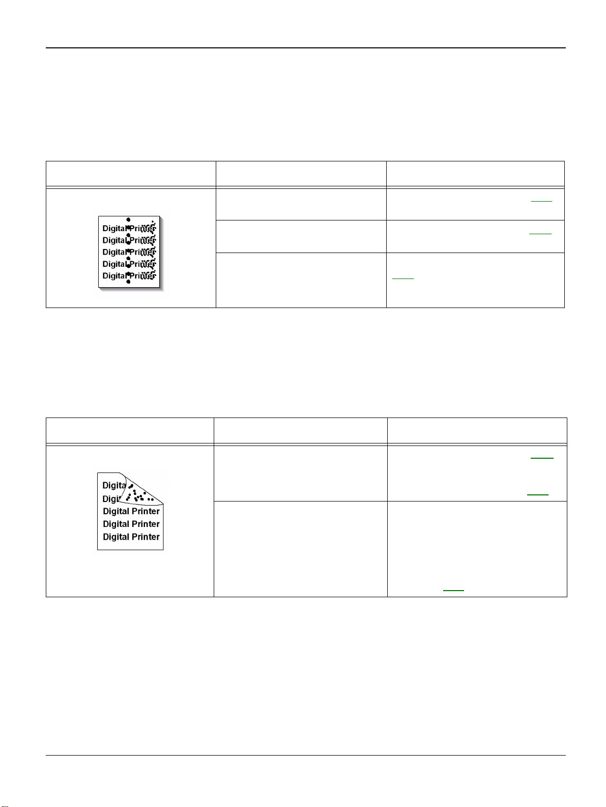
IQ 1 Vertical Black Line and Band
Description
Straight thin black vertical line occurs in the printing.
Dark black vertical band occur in the printing.
Check and Cause Solution
1. Dirty CVT Glass. 1. Clean the CVT Glass.
Image Quality
2. Damaged develop roller in the
Developer.
Deformed Doctor-blade or cleaningblade.
3. Scratched surface of the discharge roller in the print cartridge.
4. Partly depression or deformation
on the surface of the transfer roller.
2. If causes 1 and 2 occur in the print
cartridge. Install a new print cartridge,
PL 1
.
3. Install a new print cartridge, PL 1
4. Replace the transfer roller, PL 6
.
.
Workcentre PE 220 11/05 3-3
Page 50

Image Quality
IQ 2 Vertical White Line
Description
White vertical voids in the image.
Check and Cause Solution
1. Foreign matter stuck onto the
window of internal lenses of LSU
mirror.
2. Foreign matter or toner particles
between the developer roller and
blade. (In case the life of the developer has been expired, white lines
or light image occur in front of the
image.)
3. If the fuser is defective, voids
occur periodically at the top of a
black image.
1. Clean the LSU window with recommended cleaner (IPA). Clean the
window with a clean cotton swab. If
necessary, install a new LSU, PL 1
2. Install new print cartridge, PL 1
3. Open the front cover. Clean the
stripper fingers. Install parts as necessary, PL 7
If the problems are not solved,
replace the print cartridge, PL 1
.
.
.
.
3-4 11/05 Workcentre PE 220
Page 51

IQ 3 Horizontal Black Band
Description
Dark or blurry horizontal stripes on print.
Check and Cause Solution
Image Quality
1. Bad contacts of the voltage terminals to developer.
2. The rollers used in the image
development process may be contaminated.
OPC Drum = 75.5mm
Charge Roller = 37.7mm
Supply Roller = 47.5mm
Develop Roller = 35.2mm
Transfer Roller = 46.2mm
Heat Roller = 63.9mm
Pressure Roller = 75.4mm
1. Clean each voltage terminal of
the Charge, Supply, Develop and
Transfer roller.
(remove the toner particles and
paper particles)
2. Clean the component that corresponds to the repeat interval of the
defect.
If the defect persists, install a new
print cartridge, PL 1
based on the interval of the black
band.
or fuser, PL 1
Workcentre PE 220 11/05 3-5
Page 52

Image Quality
IQ 4 Black/White Spot
Description
Dark or blurry black spots on the print.
White spots occur on the print.
Check and Cause Solution
1. If dark or blurry black spots occur
periodically, the rollers in the Developer may be contaminated with foreign matter or paper particles.
(Charge roller: 37.7 mm interval
OPC drum: 75.5 mm interval)
2. If faded areas or voids occur in a
black image at intervals of 75.5
mm, or black spots occur elsewhere, the OPC drum surface is
damaged.
3. If a black image is partially broken, the transfer voltage is abnormal or the transfer roller's life has
expired.
(Approximately 50,000 sheets)
1. Run OPC cleaning Mode Print
and run the Self-test 2 or 3 times.
Refer to GP 3
If necessary, install a new print cartridge, PL 1
2. In case of 75.5 mm interval unremovable in 1, cleanly remove foreign substances stuck on the OPC
location equivalent to black spots
and white spots with a clean cloth.
3. If the roller's life is expired,
replace it. Install a new transfer
roller, PL 6
4. In case of 37.7 mm interval unremovable in 1, take measures as to
replace the print cartridge and try to
print out.
5. Clean the inside of the machine.
.
.
.
3-6 11/05 Workcentre PE 220
Page 53

IQ 5 Light Image
Description
The printed image is light, with no ghost.
Check and Cause Solution
Image Quality
1. Develop roller is contaminated
when the print cartridge is almost
consumed.
2. Ambient temperature is below
than 10°C.
3. Check shading profile. 3. Redo shading profile in the Tech
4. Bad contact caused by the toner
contamination between the high
voltage terminal in the HVPS and
the one in the set.
5. Abnormal output from the HVPS
can be caused by contamination
1. Install a new print cartridge, PL 1.
2. Wait 30 minutes after printer is
powered on before you start printing.
mode.
4. Clean the contaminated area.
5. If necessary, install a new HVPS,
PL 1
.
Workcentre PE 220 11/05 3-7
Page 54

Image Quality
IQ 6 Dark Image or Black Image
Description
The printed image is dark.
Check and Cause Solution
1. Identify if the problem is caused
by the Scanner or the LSU / Xerographics.
2. No charge voltage. 2. Clean the high voltage charge
3. Charge voltage is not turned on
due to bad contact between the
power supply in the side of the
Developer and charge terminal of
HVPS.
4. Check for CIS problem on the
Main PBA.
5. Check shading profile. 5. Perform the shading test, GP 4
1. Perform pattern test, GP 4. If pattern is good, check the scanner. If
pattern is bad, check the LSU /
Xerographics.
terminal.
3. Check the connections between
the main PBA and HVPS.
If necessary install a new main PBA
or HVPS, PL 1
4. Check the CIS FFC Cable is
properly connected.
.
.
3-8 11/05 Workcentre PE 220
Page 55

IQ 7 Uneven Density
Description
Print density is uneven.
Image Quality
Check and Cause Solution
1. The pressure force on the left
and right springs of the transfer
roller is not even, the springs are
damaged, the transfer roller is
improperly installed, or the transfer
roller bushing or holder is damaged.
2. The toner level is not even on the
developer roller.
3. Low toner in print cartridge. 3. Shake the print cartridge. If
1. Install parts as necessary, PL 6
2. Install a new print cartridge, PL 1
Image Quality is still poor, install a
new print cartridge, PL 1
.
.
.
Workcentre PE 220 11/05 3-9
Page 56

Image Quality
IQ 8 Background
Description
Light dark background on the print.
Check and Cause Solution
1. Has the customer been making a
lot of prints at less than 2% area
coverage?
Note: The print cartridge is basically designed to print 3,000 sheets
with 5% image.
2. Is recycled paper being used? 2. Image quality is not guaranteed if
3. Has the life span of the developer ended?
4. Is the movement (Up and Down)
of the transfer roller smooth?
5. The HVPS maybe defective. 5. If the problem is still present,
1. Inform the customer that low
area coverage will cause background problems.
recycle paper is used.
3. Install a new print cartridge, PL 1
4. Clean the bushings on the transfer roller, PL 6
install a new print cartridge, PL 1
HVPS as necessary, PL 1
.
, or
.
.
3-10 11/05 Workcentre PE 220
Page 57

IQ 9 Ghost (1)
Description
Ghost occurs at 75.5 mm intervals of the OPC drum on the print.
Check and Cause Solution
Image Quality
1. Bad contacts caused by contamination from toner particles between high
voltage terminal in the main body and
the electrode of the Developer.
2. The life of developer is expired. 2. Install a new print cartridge, PL 1
3. Transfer roller lifetime (50.000
sheets) has expired.
4. Abnormal low temperature (below
10°C).
5. Bad contacts caused by contamination from toner particles between high
voltage terminal in the main body and
the one in the HVPS board.
1. Clean the terminals.
3. Check the transfer roller lifetime
and if necessary install a new transfer roller, PL 6
4. Wait about 30 minutes after
power on before using the machine.
5. Install a new main PBA or
HVPS, PL 1
IQ 10 Ghost (2)
Description
Ghost occurs at 75.5 mm intervals of the OPC drum on the print.
(When printing on card stock or transparencies using manual feeder)
.
.
.
Check and Cause Solution
When printing on card stock thicker
than normal paper or transparencies such as OHP, higher transfer
voltage is required.
Workcentre PE 220 11/05 3-11
Inform the customer to Select 'Thick
Mode' on paper type menu from the
software application and after using
returning to the original mode is
recommended.
Page 58

Image Quality
IQ 11 Ghost (3)
Description
White ghost occurs in the black image printing at 47.5mm intervals.
Check and Cause Solution
1. The life of the developer may be
expired.
2. Possible abnormal voltage and
bad contact of the terminal of the
supply roller in the print cartridge.
IQ 12 Ghost (4)
Description
Ghost occurs at 47.5mm(or 63.9mm) intervals.
Check and Cause Solution
1. The temperature of the fuser is
too high because the thermistor is
contaminated.
1. Install a new print cartridge, PL 1.
2. Install a new print cartridge, PL 1
CAUTION
Take care not to bend or break the
thermistor.
.
1. Clean the heat roll, pressure roll
and thermistor, PL 7
install a new fuser, PL 1
3-12 11/05 Workcentre PE 220
. If necessary
.
Page 59
IQ 13 Contamination on the Face of Page
Description
The background on the face of the printed page is contaminated.
Check and Cause Solution
Image Quality
1. Toner leakage due to improperly
sealed developer.
2. The transfer roller maybe contamInated.
3. The fuser roll may be contaminated
IQ 14 Contamination on Back of Page
Description
The back of the page is contaminated at 47 mm intervals.
Check and Cause Solution
1. Transfer roller is contaminated. 1. Run DRUM Cleaning Mode, GP 3.
1. Install a new print cartridge, PL 1.
2. Run DRUM Cleaning Mode, GP 3
Make 2 or 3 prints
3. Inspect and clean the fuser roll,
PL 7
. Replace if necessary.
Make 2 or 3 prints
2. Replace the transfer roller, PL 6
.
.
2. Pressure roller is contaminated. CAUTION
Take care not to bend or break the
thermistor.
3. Clean the heat roll, pressure roll
and thermistor. If necessary install a
new fuser, PL 1
Workcentre PE 220 11/05 3-13
.
Page 60

Image Quality
IQ 15 Blank Page Print out (1)
Description
Blank page is printed.
Check and Cause Solution
1. Bad ground contacts in OPC
and/or developer.
2. Check the Scanner Cover is
properly closed.
3. Check shading profile. 3. Redo shading profile in the tech
4. Check white/black reference voltage on Main PBA.
IQ 16 Blank Page Print out (2)
Description
Blank page is printed.
One or several blank pages are printed.
When the machine turns on, several blank pages print.
Check and Cause Solution
1. Bad ground contacts in OPC
and/or developer.
1. Remove contamination from the
terminals of the developer and the
OPC unit.
2. Room light can pass through a
thin original.
mode, refer to GP 4
4. Replace the Main PBA, PL 1
1. Remove contamination from the
terminals of the developer.
.
.
2. Abnormal solenoid. 2. Perform the engine self test
using Engine Test Mode to check
the Solenoid, GP 7
3. Turn the power off, then on.
Resend the job.
4. Install a new Main PBA, PL 1
3-14 11/05 Workcentre PE 220
.
.
Page 61

IQ 17 Misregistration
Description
Printing begins at wrong position on the paper.
Check and Cause Solution
Image Quality
Wrong sense time caused by defective feed sensor
actuator.
Replace the defective actuator, PL 6.
Workcentre PE 220 11/05 3-15
Page 62

Image Quality
IQ 18 Printed Vertical Lines Not Straight
Description
When printing, vertical lines are not straight.
Check and Cause Solution
1. Check stability of 24V supply to LSU. 1. 24V stable - Replace LSU, PL 1.
24V unstable replace SMPS, PL 1
If the problem persists replace the main PBA, PL 1
.
.
3-16 11/05 Workcentre PE 220
Page 63

Image Quality
IQ 19 Blurred Image
Description
Image is blurred.
Check and Cause Solution
1. Check the gap between original and platen glass. 1. A gap of more than 0.5 mm can cause a blurred
image. Ensure rollers and cover close correctly.
Replace as necessary, PL 1
.
Workcentre PE 220 11/05 3-17
Page 64

Image Quality
Page intentionally blank
3-18 11/05 Workcentre PE 220
Page 65

Repairs/Adjustments
4. Repairs/Adjustments
REP 1 MP Tray ........................................................................................................................ 4-3
REP 2 Pick Up Roller ............................................................................................................... 4-4
REP 3 Front Cover ................................................................................................................... 4-4
REP 4 Cassette Tray ................................................................................................................ 4-5
REP 5 Rear Cover .................................................................................................................... 4-5
REP 6 Right Cover ................................................................................................................... 4-6
REP 7 Left Cover ..................................................................................................................... 4-7
REP 8 Scan Assembly ............................................................................................................. 4-8
REP 9 ADF Housing ................................................................................................................. 4-9
REP 10 OPE Unit ................................................................................................................... 4-11
REP 11 Platen Housing .......................................................................................................... 4-12
REP 12 Middle Cover ............................................................................................................. 4-14
REP 13 HVPS ........................................................................................................................ 4-15
REP 14 Main PBA .................................................................................................................. 4-15
REP 15 RX Drive .................................................................................................................... 4-16
REP 16 Fuser ......................................................................................................................... 4-17
REP 17 Engine Shield (LIU PBA, SMPS) .............................................................................. 4-21
REP 18 LSU ........................................................................................................................... 4-22
REP 19 Paper Path Frame ..................................................................................................... 4-23
Workcentre PE 220 11/05 4-1
Page 66

Repairs/Adjustments
Page intentionally blank
4-2 11/05 Workcentre PE 220
Page 67
Repairs/Adjustments
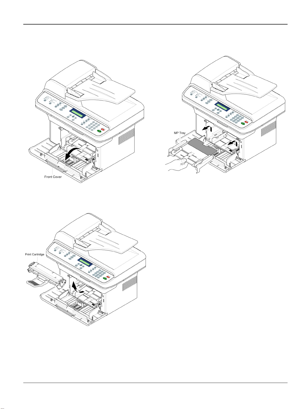
REP 1 MP Tray
1. Open the Front Cover.
Figure 1
2. Remove the Print Cartridge.
3. Hold the MP Tray and pull it in the direction of the arrow.
Figure 3
Figure 2
Workcentre PE 220 11/05 4-3
Page 68

Repairs/Adjustments
REP 2 Pick Up Roller
1. Before you remove the Pick Up Roller,
you should remove:
- MP Tray (Refer to REP 1)
2. To exchange the Pick Up Sponge, pull
apart Pick Up Housing U while pressing
the hooks on both sides of Pick Up Housing B.
REP 3 Front Cover
1. Open the Front Cover.
Figure 1
2. To remove the Front Cover, carefully pull
the part below the right side of the Front
Cover in the direction of the arrow (left).
Figure 2
4-4 11/05 Workcentre PE 220
Page 69

Repairs/Adjustments
REP 4 Cassette Tray
1. Open the Cassette Tray.
Figure 1
2. To remove the Cassette Tray, carefully lift
the knob in the direction of the arrow while
holding the Set (left).
REP 5 Rear Cover
1. Remove four screws securing the Rear
Cover.
Figure 1
2. Open the Jam Cover.
Figure 2
Workcentre PE 220 11/05 4-5
Figure 2
Page 70
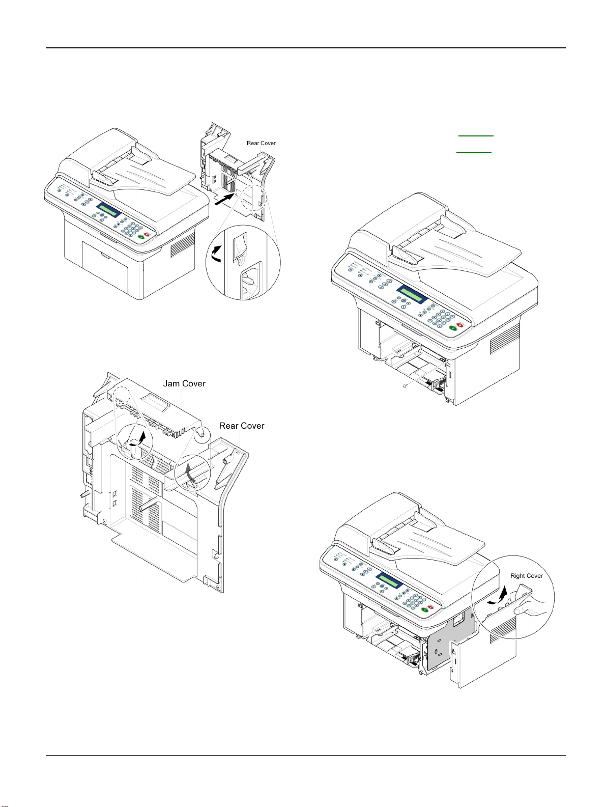
Repairs/Adjustments
3. To remove the Rear cover, make sure the
right Power Switch does not get jammed
to the Rear Cover.
Figure 3
4. If necessary, remove the Jam Cover in
the direction of arrow.
REP 6 Right Cover
1. Before you remove the Right Cover, you
should remove:
- Front Cover (Refer to REP 3)
- Rear Cover (Refer to REP 5)
2. Remove the screw securing the Right
Cover.
Figure 4
Figure 1
3. Apply light pressure to the back of the
Right Cover and pull it to the right side in
the direction of the arrow.
Figure 2
4-6 11/05 Workcentre PE 220
Page 71

Repairs/Adjustments
REP 7 Left Cover
1. Before you remove the Left Cover, you
should remove:
- Front Cover (Refer to REP 3)
- Rear Cover (Refer to REP 5)
2. Remove the screw securing the Left
Cover.
3. Apply light pressure to the back of the Left
Cover and pull it to the left side in the
direction of the arrow.
Figure 1
Figure 2
4. Unplug the Speaker Connector from the
Main PBA.
Figure 3
5. If necessary, remove the two screws
securing the Speaker.
Workcentre PE 220 11/05 4-7
Page 72

Repairs/Adjustments
REP 8 Scan Assembly
1. Before you remove the Scan Assembly,
you should remove:
- Rear Cover (Refer to REP 5)
- Right Cover (Refer to REP 6)
- Left Cover (Refer to REP 7)
2. Remove two screws from the Middle
Cover and remove the screw securing the
Ground Cable.
3. Unplug the three Connectors (ADF, Scan
Motor, OPE) and Flat Cable-CIS.
Figure 2
4. Release the Scan Assembly in the direction of the arrow.
Figure 1
Figure 3
4-8 11/05 Workcentre PE 220
Page 73
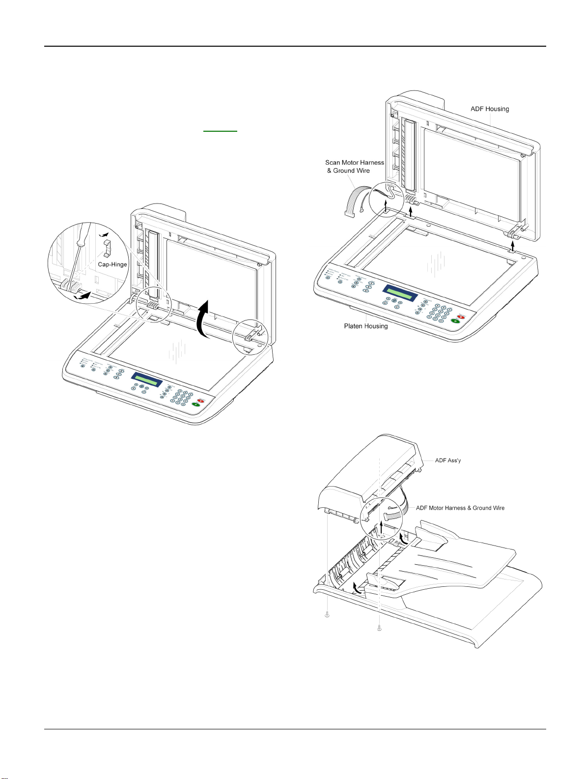
REP 9 ADF Housing
1. Before you remove the ADF Housing, you
should remove:
- Scan Assembly (Refer to REP 8)
2. Open the ADF Housing and insert a flatblade screwdriver into the slot and
remove the Cap-Hinge from the Platen
Housing and ADF Housing.
Repairs/Adjustments
Figure 1
3. Remove the ADF Housing from the Platen
Housing, while carefully releasing the
ADF Motor Harness and ground wire from
the Platen Housing.
Figure 2
4. Remove two screws securing the ADF
Assembly. Carefully release the ADF
Motor Harness and ground wire from the
Platen Cover..
Figure 3
Workcentre PE 220 11/05 4-9
Page 74

Repairs/Adjustments
5. If necessary, remove two screws securing
the TX Stacker Assembly.
Figure 4
6. Open the Open Cover and remove the
Open Cover in the direction of the arrow.
7. Pull and rotate the Bushing until it reaches
the slot, then lift the Pick Up Unit.
Figure 6
8. Remove two screws securing the ADF
Upper and insert a flat-blade screwdriver
in to the slot and remove the ADF Upper.
Figure 5
Figure 7
4-10 11/05 Workcentre PE 220
Page 75
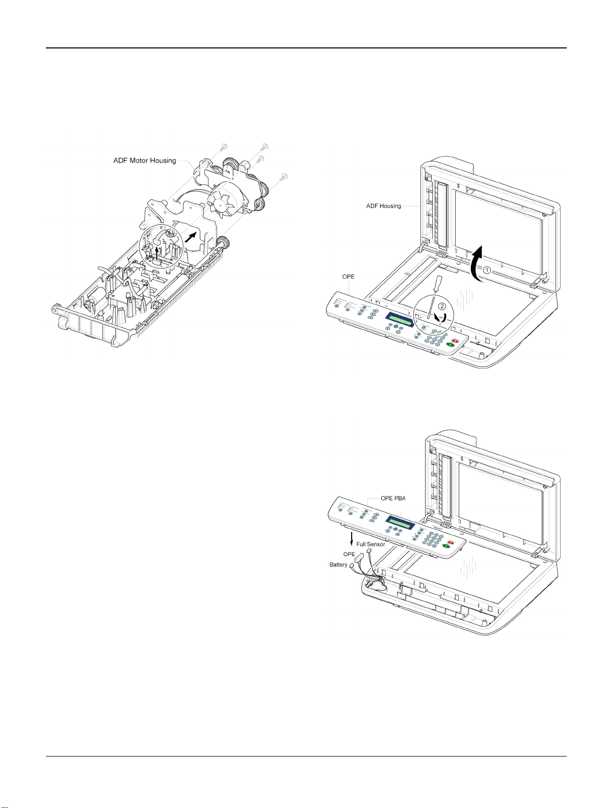
Repairs/Adjustments
9. Unplug the Connector from the ADF PBA
and remove four screws securing the ADF
Motor Housing and remove it in the direction of the arrow.
Figure 8
REP 10 OPE Unit
1. Open the ADF Housing and insert a flatblade screwdriver into the crack and
remove the OPE Unit from the Platen
Housing.
Figure 1
2. Unplug the three Connectors (Battery,
OPE, Full Sensor).
Figure 2
3. Remove the screws securing the OPE
PBA and remove it.
4. Release the Contact Rubbers.
5. Release the Keys.
Workcentre PE 220 11/05 4-11
Page 76

Repairs/Adjustments
REP 11 Platen Housing
1. Before you remove the Platen Housing,
you should remove:
- Scan Assembly (Refer to REP 8)
- ADF Housing (Refer to REP 9)
- OPE Unit (Refer to REP 10)
2. Remove five screws from the Scan Upper
and remove it from the Scan Lower.
4. Push the Holder in the direction of arrow
and remove the Belt, as shown below.
(The CIS will come out at the same time.)
Figure 3
5. Release the Belt and Flat Cable from the
CIS.
Figure 1
3. Take out the Battery.
Figure 2
Figure 4
4-12 11/05 Workcentre PE 220
Page 77
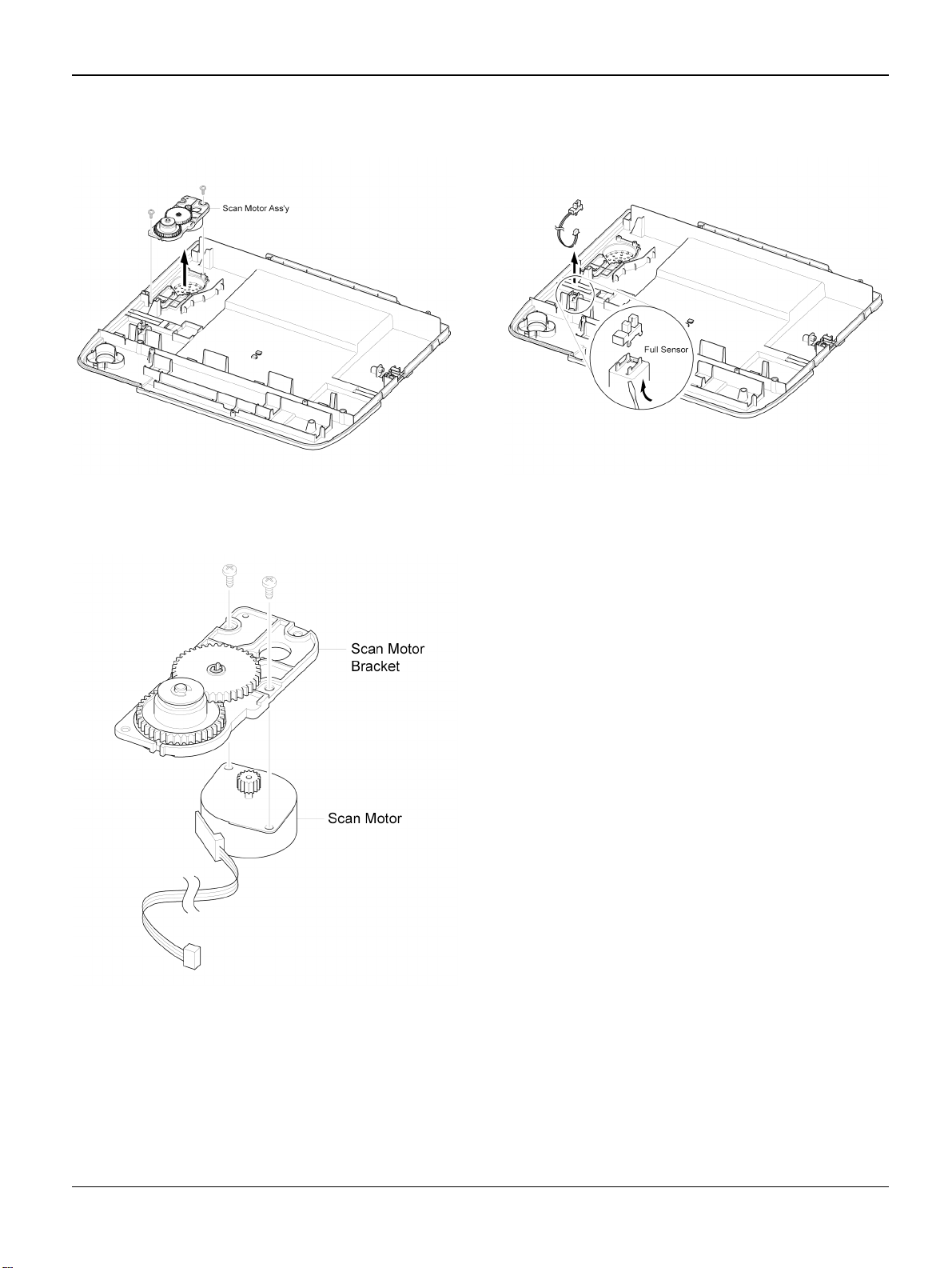
Repairs/Adjustments
6. Remove two screws securing the Scan
Motor Assembly and remove it.
Figure 5
7. If necessary, remove two screws securing
the Scan Motor and remove it.
8. Using a flat-blade screwdriver remove the
Full Sensor.
Figure 7
Figure 6
Workcentre PE 220 11/05 4-13
Page 78
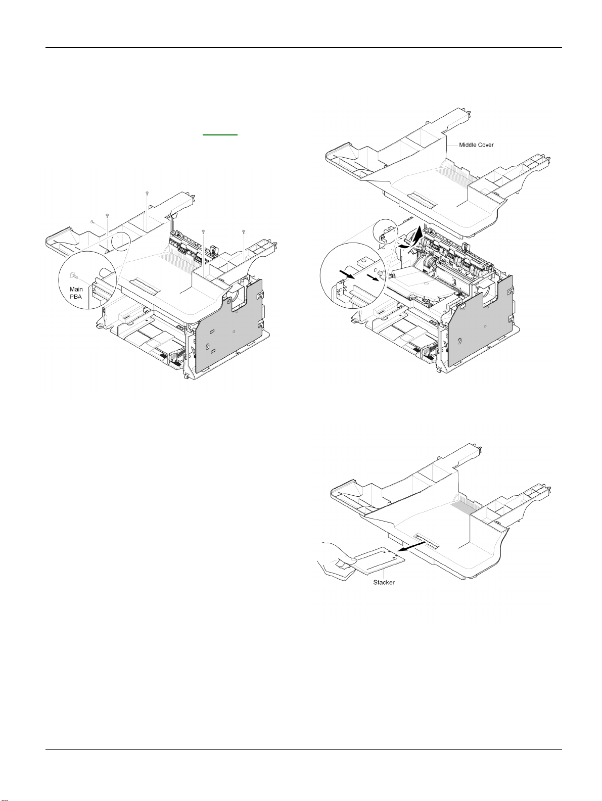
Repairs/Adjustments
REP 12 Middle Cover
1. Before you remove the Middle Cover, you
should remove:
- Scan Assembly (Refer to REP 8)
2. Remove five screws securing the Middle
Cover.
3. Carefully release the Middle Cover from
the Main PBA.
Figure 1
Figure 2
4. If necessary, take out the Stacker.
Figure 3
4-14 11/05 Workcentre PE 220
Page 79

Repairs/Adjustments
REP 13 HVPS
1. Before you remove the HVPS, you should
remove:
- Scan Assembly (Refer to REP 8)
- Middle Cover (Refer to REP 12)
2. Remove five screws securing the HVPS
and remove it with the HVPS Ground.
REP 14 Main PBA
1. Before you remove the Main PBA, you
should remove:
- Scan Assembly (Refer to REP 8)
- Middle Cover (Refer to REP 12)
2. Unplug the all Connectors from the Main
PBA, as shown below.
Figure 1
3. Unplug the Connector from the HVPS.
HVPS Ground
Figure 2
Figure 1
3. Remove six screws securing the Main
PBA and remove it.
Figure 2
Workcentre PE 220 11/05 4-15
Page 80

Repairs/Adjustments
REP 15 RX Drive
1. Before you remove the RX Drive, you
should remove:
- Scan Assembly (Refer to REP 8)
- Middle Cover (Refer to REP 12)
- Main PBA (Refer to REP 14)
2. If necessary, remove Bracket Port,
Bracket Main PBA and Ground.
3. Remove two screws securing the Engine
Shield and remove six screws securing
the Frame, then remove the RX Drive in
the direction of the arrow.
Figure 2
4. Remove the Connector.
Figure 1
Figure 3
4-16 11/05 Workcentre PE 220
Page 81

Repairs/Adjustments
5. Release the four Gears (RDCN, OPC,
Fuser, Feed) from the Frame.
Figure 4
6. Remove four screws securing the Motor
Bracket and remove it. Then remove two
screws securing the Motor and remove it.
REP 16 Fuser
1. Before you remove the Fuser, you should
remove:
- Scan Assembly (Refer to REP 8)
- Middle Cover (Refer to REP 12)
2. Unplug the two Connectors from the
SMPS and Main PBA.
Figure 5
Figure 1
3. Remove four screws securing the Fuser
and remove it.
Figure 2
Workcentre PE 220 11/05 4-17
Page 82

Repairs/Adjustments
4. Remove the Lever-M-Act Exit in the direction of arrow.
Figure 3
5. Remove the Cover-M-Safety.
6. Remove the Cover-M-Guide Exit.
Figure 5
Figure 4
4-18 11/05 Workcentre PE 220
Page 83

Repairs/Adjustments
7. Rotate the Holder in the direction of the
arrow which is attached to the Exit Roller
F/Down and Exit Gear (DRV17). (The
Roller_Main, Roller_FR, F/Down Holder,
Spring will come out at the same time.)
9. Pull out the Thermostat and release the
CBF Harness.
Figure 8
10.Remove the screw securing the Harness
then take out the Thermistor.
Figure 6
Note: If you don't follow the direction above
the Spring will come out forcing the
Roller_Main, Roller_FR, F/Down Holder
inside the Frame Assembly.
8. Remove two screws securing the Thermo
Cap and remove it.
Figure 7
Figure 9
Workcentre PE 220 11/05 4-19
Page 84

Repairs/Adjustments
11. Release the CBF Harness from the Halogen Lamp and remove two screws securing the Halogen Lamp.
Figure 10
12.Remove two screws securing the CoverM and remove it.
CAUTION
Do not touch the lamp body (glass). Contamination from your fingers can cause the lamp
to fail.
13.Take out the Halogen Lamp in the direction of arrow.
Figure 12
Figure 11
4-20 11/05 Workcentre PE 220
Page 85

Repairs/Adjustments
REP 17 Engine Shield (LIU PBA, SMPS)
1. Before you remove the Engine Shield, you
should remove:
- Scan Assembly (Refer to REP 8)
- Middle Cover (Refer to REP 12)
2. Unplug all Connectors from the SMPS
and LIU PBA.
Figure 1
3. Remove six screws securing the Engine
Shield and release the Harness. Carefully
release the Engine Shield from the Actuator Feed Sensor Lever.
4. If only removing the SMPS, remove the
Rear Cover (refer to REP 5) and unplug
the Fuser Connector. Remove six screws
securing the SMPS. Unplug the Connector from the Main PBA and carefully
release the SMPS.
Figure 3
5. If only removing the LIU PBA, remove the
Rear Cover (refer to REP 5) and remove
two screws securing the LIU PBA. Unplug
the Connector from the Main PBA and
release the LIU PBA.
Figure 4
Figure 2
Workcentre PE 220 11/05 4-21
Page 86

Repairs/Adjustments
REP 18 LSU
CAUTION
Do not touch the LSU Glass Window. Contamination on the LSU Glass Window can
lead to Image Quality problems.
1. Before you remove the LSU, you should
remove:
- Scan Assembly (Refer to REP 8)
- Middle Cover (Refer to REP 12)
2. Remove three screws securing the LSU
and remove it. Unplug the two Connectors
from the LSU.
Figure 1
4-22 11/05 Workcentre PE 220
Page 87

Repairs/Adjustments
REP 19 Paper Path Frame
1. Before you remove the Paper Path
Frame, you should remove:
- Scan Assembly (Refer to REP 8)
- Middle Cover (Refer to REP 12)
- Fuser (Refer to REP 16)
- Engine Shield (Refer to REP 17)
2. Remove four screws securing the Paper
Path Frame and remove it in the direction
of the arrow.
4. Remove the screw securing the SolenoidMP and remove it. .
Figure 3
Figure 1
3. Remove the Transfer Roller from the
Frame.
Figure 2
Workcentre PE 220 11/05 4-23
Page 88

Repairs/Adjustments
Page intentionally blank
4-24 11/05 Workcentre PE 220
Page 89

Spare Parts List
5. Spare Parts List
PL 1 Main Assembly ................................................................................................................. 5-2
PL 2 ADF Assembly ................................................................................................................ 5-4
PL 3 Platen Cover Assembly ................................................................................................... 5-6
PL 4 ADF Platen Assembly ..................................................................................................... 5-8
PL 5 OPE Unit ....................................................................................................................... 5-10
PL 6 Paper Path Assembly ................................................................................................... 5-12
PL 7 Fuser Unit ..................................................................................................................... 5-14
PL 8 Main Frame Assembly .................................................................................................. 5-16
PL 9 MP Tray Assembly ........................................................................................................ 5-18
PL 10 Common Hardware & General Service Items ............................................................. 5-20
Workcentre PE 220 11/05 5-1
Page 90

Spare Parts List
PL 1 Main Assembly
5-2 11/05 Workcentre PE 220
Page 91

Spare Parts List
PL 1 Main Assembly
Item Part Number Description Qt’y Remark
0 SET
1 ELA HOU-FRAME LOWER (REFER TO PL 8
2 122N00243 UNIT-LSU 1
3 CBF HARNESS-LSU 1
4 INITIAL(1K) PRINT CARTRIDGE 1
5 101N01380 FUSER_110V (REFER TO PL 7
5 101N01381 FUSER_220V (REFER TO PL 7
6 SHEILD-P-ENGINE 1
7 GROUND-P-HVPS 2
8 105N02066 SMPS 110V 1
8 105N02067 SMPS 220V 1
9 140N63039 PBA SUB-LIU WESTERN EUROPE 1
9 140N63038 PBA SUB-LIU US/CANADA/SAUDI ARABIA/RUSSIA... 1
10 CBF HARNESS HVPS 1
11 HARNESS CLAMP 1
12 CBF HARNESS LIU 1
13 116N00244 ELA UNIT-TERMINAL TR L 5
13-1 SPRING ETC-HV LARGE 1
13-2 ICT-SHAFT HV LARGE 1
14 015N00557 PLATE-P-CHANNEL 1
15 105N02068 HVPS 1
16 NOT USED
17 BRACKET-P-MAIN BOARD 1
18 117N01691 GROUND-P-MAIN BOARD 1
19 030N00711 BRACKET-P-PORT 1
20 140N63040 PBA MAIN 1
21 ELA HOU-FULL SENSOR HARNESS 1
21-1 PHOTO INTERRUPTER 1
21-2 CBF HARNESS-JAM_SENSOR 1
22 002N02429 COVER-M-SIDE R 1
23 002N02430 ELA HOU-COVER SIDE L 1
23-1 002N02431 COVER-M-SIDE L 1
23-2 130N01412 SPEAKER 1
23-3 IPR-UNIT FIXING BRACKET 1
24 002N02432 MEA-COVER FRONT 1
24-1 COVER-M-FRONT 1
24-2 050N00480 TRAY-M-CASSETTE 1
24-3 TRAY-M-EXTENSION LARGE 1
24-4 TRAY-M-EXTENSION SMALL 1
25 002N02433 ELA HOU-COVER MIDDLE 1
25-1 COVER-M-MIDDLE 1
25-2 PMO-M-STACKER 1
25-3 SHEET-FAN 1
26 002N02435 MEA UNIT-COVER REAR 1
26-1 COVER-M-REAR 1
26-2 MEA UNIT-COVER JAM 1
26-2-1 COVER-M-JAM 1
26-2-2 COVER-M-JAM DUMMY 1
27 002N02435
27-1 021N02251 CAP-M-HINGE 2
28
29 AC POWER CORD (US VER.) (REFER TO PL 10
30 USB CABLE (REFER TO PL 10
31 TELEPHONE LINE CORD (US VER.) (REFER TO PL 10
ELA HOU-SCAN (ALSO REFER TO PL 2
MEA UNIT-MP TRAY (REFER TO
)1
)1
PL 9)
)1
)1
, PL 3 & PL 4)
)1
)1
1
1‘
Workcentre PE 220 11/05 5-3
Page 92

Spare Parts List
PL 2 ADF Assembly
5-4 11/05 Workcentre PE 220
Page 93

Spare Parts List
PL 2 ADF Assembly
Item Part Number Description Qt’y Remark
0 002N02441 ELA HOU-ADF 1
1 002N02444 ELA HOU-ADF LOWER 1
1-1 COVER-M-ADF LOWER 1
1-2 002N02445 ELA HOU-ADF MOTOR 1
1-2-1 GEAR-IDLE 35 ADF 3
1-2-2 007N01369 GEAR-CLUTCH 39 1
1-2-3 GEAR-SWING 31/20 ADF 1
1-2-4 GEAR-58/25 ADF 1
1-2-5 007N01370 GEAR-40/21 ADF 2
1-2-6 BRACKET-P-MOTOR 1
1-2-7 MOTOR STEP-ADF 1
1-2-8 IMPELLER-ADF 1
1-2-9 BRACKET-M-GEAR 1
1-3 140N63041 PBA SUB-ADF 1
1-4 GROUND-P-ADF 1
1-5 CBF HARNESS-ADF 1
1-6 ROLLER-DRIVE 1
1-7 013N13842 PMO-BUSH 4
1-8 007N01368 SHAFT-M-FEED GEAR 38 1
1-9 RING-C 1
1-10 130N01413 PMO-ACTUATOR SCAN SENSOR 1
1-11 009N01512 SPRING-CS 3
1-12 115N00856 MEC-BRUSH ANTISTATIC 1
1-13 009N01513 SPRING ETC-TORSION DOC (CC2-F) 3
1-14 015N00559 PLATE-M_WHITE BAR 1
1-15 PMO-ACTUATOR DOC SENSOR 1
1-16 GEAR-CLUTCH 29 1
1-17 PMO-ACTUATOR REGI SENSOR 1
1-18 ROLLER-EXIT 1
1-19 GUIDE-STACKER SUB 2
1-20 SHAFT-IDLE FEED 2
2 002N02446 MEA-ADF UPPER 1
2-1 COVER-M-ADF UPPER 1
2-2 500N00107 MEA UNIT-HOLDER ADF 1
2-2-1 HOLDER-M-ADF 1
2-2-2 019N00842 SHEET-ADF HOLDER 1
2-2-3 019N00566 ADF RUBBER 1
2-2-4 019N00843 SPRING ETC-PAD 1
3 002N02447 MEA-COVER OPEN 1
3-1 COVER-M-ADF OPEN 1
3-2 130N01414 MEA UNIT PICKUP ADF 1
3-2-1 022N02190 MEC-ADF ROLLER ASSEMBLY 1
3-2-2 013N13842 PMO-BUSH 1
3-2-3 022N02191 MEC-PICK UP ROLLER ASSEMBLY 1
3-3 038N00462 PMO-GUIDE PAPER 1
Workcentre PE 220 11/05 5-5
Page 94

Spare Parts List
PL 3 Platen Cover Assembly
5-6 11/05 Workcentre PE 220
Page 95

Spare Parts List
PL 3 Platen Cover Assembly
Item Part Number Description Qt’y Remark
0 002N02448 MEA-COVER PLATEN 1
1 002N02436 COVER-M-PLATEN 1
2 095N00274 SHEET-WHITE SPONGE 1
3 038N00405 PMO-TX STACKER 1
4 38N00410 PMO-DOC GUIDE(R) 1
5 38N00406 PMO-DOC GUIDE(L) 1
6 028N00321 IPR-WASHER SPRING CU 2
7 007N01178 GEAR-PINION 1
8 009N01514 SPRING ETC-FEED 6
9 SHAFT PINCH 1
10 022N02014 PMO-ROLL PINCH 2
11 SHAFT-IDLE FEED 2
12 022N02019 RPR-ROLLER EXIT IDLE 2
13 050N00479 MEA-TX STACKER 1
Workcentre PE 220 11/05 5-7
Page 96

Spare Parts List
PL 4 ADF Platen Assembly
5-8 11/05 Workcentre PE 220
Page 97

Spare Parts List
PL 4 ADF Platen Assembly
Item Part Number Description Qt’y Remark
0 002N02443 ELA HOU-PLATEN 1
1 002N02449 ELA HOU-SCAN LOWER 1
1-1 002N02450 COVER-M-SCAN LOWER 1
1-2 101N01345 ELA HOU-SCAN MOTOR 1
1-2-1 BRACKET-M-SCAN MOTOR 1
1-2-2 127N07398 MOTOR STEP-SCAN 1
1-2-3 GEAR-TIMING 1
1-2-4 PMO-HOLDER BELT 1
1-2-5 RING-E 1
1-2-6 GEAR-IDLE 1
1-2-7 GEAR-REDUCTION 1
1-3 130N01415 CONTACT IMAGE SENSOR (CIS) 1
1-4 CBF SIGNAL-CIS FFC 1
1-5 SHAFT-CIS 1
1-6 023N01140 PMO-HOLDER BELT_1 1
1-7 PMO-HOLDER BELT_2 1
1-8 PMO-PULLEY 1
1-9 009N01515 SPRING ETC-BELT 1
1-12 121N01112 BATTERY 2
1-13 152N11632 ELA HOME-FULL SENSOR HARNESS 1
1-14 109N00542 BELT-TIMING GEAR 1
2 109N00650 MEA-SCAN UPPER 1
2-1 002N02438 COVER-M-SCAN UPPER 1
2-2 091N80223 LABEL(P)-SHADING 1
2-3 062N00266 GLASS-ADF 1
2-4 090N00161 GLASS-PLATEN 1
Workcentre PE 220 11/05 5-9
Page 98

Spare Parts List
PL 5 OPE Unit
5-10 11/05 Workcentre PE 220
Page 99

Spare Parts List
PL 5 OPE Unit
Item Part Number Description Qt’y Remark
0 002N02442 ELA HOU-OPE(XEROX) 1
1 002N02437 COVER-M-OPE 1
2 110N01390 RUBBER-TEL 1
3 110N01391 RUBBER-SCROLL 1
4 140N63042 PBA SUB-OPE 1
5 003N00972 KEY-M_SHIFT 1
6 029N00367 KEY-M_STATUS 1
7 003N00969 KEY-M_TEL_R2_XRX 1
8 003N00893 KEY-M-STOP 1
9 003N00970 KEY-M_START_XRX 1
10 029N00368 KEY-M_FAX 1
11 003N00971 KEY-M_SCROLL_R2X 1
12 152N11627 CBF HARNESS-OPE 1
13 LCD DISPLAY 1
14... 002N02421 SHEET-OVERLAY ENGLISH 1
14... 002N02422 SHEET-OVERLAY SPANISH 1
14... 002N02423 SHEET-OVERLAY BRAZILIAN PORTUGUESE 1
14... 002N02424 SHEET-OVERLAY FRENCH 1
14... 002N02425 SHEET-OVERLAY RUSSIAN 1
Workcentre PE 220 11/05 5-11
Page 100

Spare Parts List
PL 6 Paper Path Assembly
5-12 11/05 Workcentre PE 220
 Loading...