

Page 1

Operating Instructions
HOB
GBGB
GB
GBGB
English, 2
ET 6124
ET 6124 X
ET 7424
Contents
GB
Installation, 2-3
Positioning
Connecting the hob
Disposal
Description of the appliance, 4-5
Control panel
Cooking zone description
Start-up and use, 6
Turning on the hob
Turning off the hob
The booster
The safety devices, 7
Pan recognition
What cookware to use
Acoustic signal
Safety cut out
Overheating protection device
Precautions and tips, 8
Practical advice on using the appliance
General safety
Care and maintenance, 9
Switching the appliance off
Cleaning the appliance
Disassembling the hob
Page 2
Installation
GB
! Before operating your new appliance please read
this instruction booklet carefully. It contains
important information concerning the safe operation,
installation and maintenance of the appliance.
! Please keep these operating instructions for future
reference. Pass them on to possible new owners of
the appliance.
Positioning
! Keep all packaging materials out of the reach of
children. It may present a choking or suffocation
hazard (see Precautions and tips).
! The appliance must be installed by a qualified
professional in accordance with the instructions
provided. Incorrect installation may damage
property or cause harm to people or animals.
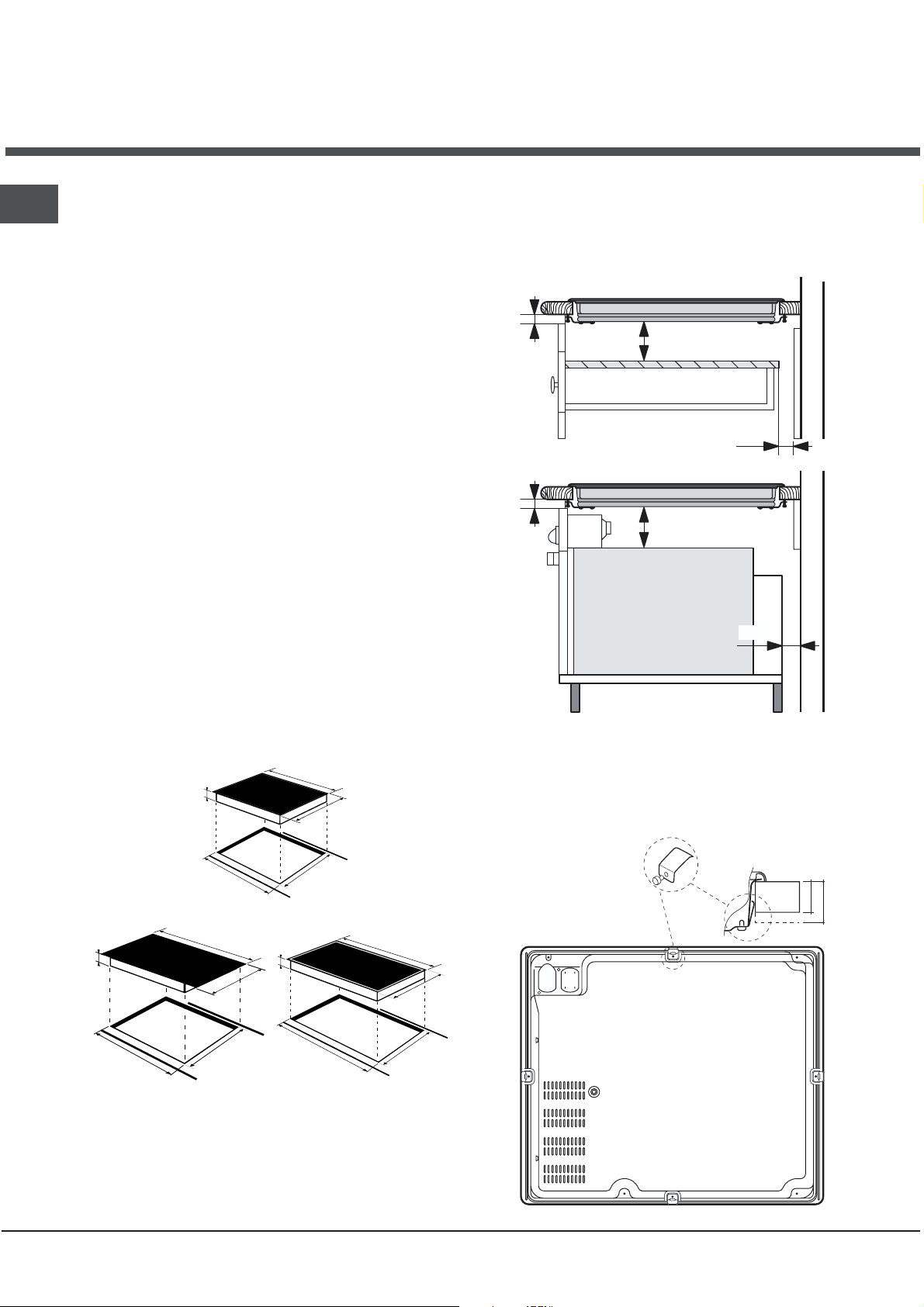
Built-in appliance
Use the appropriate cabinet to ensure that the
appliance functions properly.
The supporting surface must be heat-resistant up
to a temperature of approximately 100°C.
If the appliance is to be installed above an oven,
the oven must have a forced ventilation cooling
system.
Avoid installing the hob above a dishwasher: if
this cannot be avoided, place a waterproof
separation device between the two appliances.
Depending on the hob you want to install, the
cabinet must have the following dimensions (see
figure):
590
48
520
At a minimum of 40 mm from the back panel and
600 mm from any other vertical surfaces.
So that a minimum distance of 20 mm is
maintained between the installation cavity and the
cabinet underneath.
min. 20 mm
5 mm
COMPARTMENT
min. 40 mm
min. 20 mm
5 mm
FAN-ASSISTED
OVE N
min. 40 mm
Fixing
The appliance must be installed on a perfectly level
supporting surface.
Any deformities caused by improper fixing could
change the features and the operation of the hob.
REAR SPRING ASSEMBLY
560 +/- 1
690
48
520
490 +/- 1
785
48
560 +/- 1
490 +/- 1
750 +/- 1
Ventilation
To allow adequate ventilation and to avoid
overheating of the surrounding surfaces the hob
should be positioned as follows:
2
510
490+/- 1
FRONT OF HOB
HOB FROM BELOW
KITCHEN
WORKTOP
30
40
Page 3
Connecting the hob
The electrical safety of this appliance can only be
guaranteed if the latter is correctly and efficiently
earthed, in compliance with regulations on electrical
safety. Always ensure that this vital safety measure
has been taken. If you have any doubts, call in a
qualified technician to check the electrical system
thoroughly.
The manufacturer denies all responsibility for damage
resulting from a system which has not been earthed
correctly.
Before powering the appliance, check whether the
technical characteristics featured on the appliance
data plate correspond with those of the mains
electrical system.
Check that the current load of the mains supply and of
the power sockets is suitable for the maximum power
of the appliance, indicated on the appliance data
plate. If in doubt, contact a qualified professional.
2. Loosen the cable
clamp screw and remove
it, using a screwdriver as
a lever (see figure).
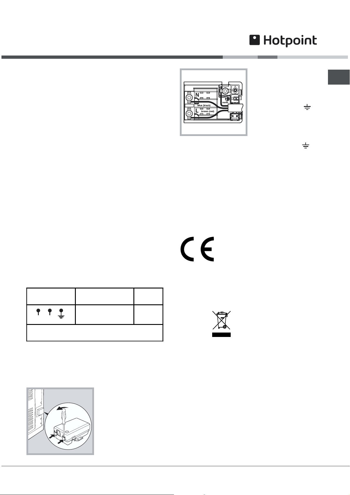
3. Remove the wire
contact screws L-Nthen fasten the wires
under the screw heads,
respecting the colour
code: Black/Blue (N),
Red/Brown (L) and Bare
Wire/Yellow-Green ( ).
Position the power supply cable wires according to
the indications in the table.
Once the connections have been made, tighten all
the terminal screws fully.
Fasten the supply cable in place with the clamp and
close the cover of the terminal board.
GB
,
Disconnect the appliance from the electricity supply
before all operations.
Connect your hob to the electrical system by means of a
junction box:junction box:
junction box: if the appliance is connected
junction box:junction box:
permanently to the mains, an
breakerbreaker
breaker, accessible if necessary, with a minimum
breakerbreaker
contact opening of 3 mm should be installed.
Valid only for models with a power supply cable
Some models are supplied with a single-phase power
supply cable, and should consequently only be connected
to the single-phase mains. Observe the wire colours, as
indicated in the diagram attached.
Electrical
connections
N
L
* Application of the simultaneity coefficient in
accordance with cei 60335-2-6 norm
Voltage, Frequency
omnipolar circuitomnipolar circuit
omnipolar circuit
omnipolar circuitomnipolar circuit
GB 220-240V
-1+N~50 Hz
Fuses,
Sections
25 A*
2,5 mm²
Valid only for models without a power supply cable
Some models are not fitted with a power supply cable,
as the cable should be sized according to the type of
electrical connection in use (see connection table
below). To connect the cable, proceed as follows:
1. Open the terminal
board by inserting a
screwdriver into the
side tabs of the cover.
Use the screwdriver as
a lever by pushing it
down to open the cover
(see diagram).
! If the hob is fitted above a built-in oven, the hob and the
oven must be connected to the mains separately for safety
reasons and to simplify operations when it is necessary to
pull the oven out for some reason.
This appliance conforms to the
following European Economic
Community directives:
- 73/23/EEC dated 19/02/73 (Low Voltage) and subsequent
amendments;
- 89/336/EEC dated 03/05/89 (Electromagnetic
Compatibility) and subsequent amendments;
- 93/68/EEC dated 22/07/93 and subsequent amendments.
Disposal
When disposing of packaging material: observe local
legislation so that the packaging may be reused.
The European Directive 2002/96/EC relating to Waste
Electrical and Electronic Equipment (WEEE) states that
household appliances should not be disposed of using
the normal solid urban waste cycle. Exhausted
appliances should be collected separately in order to
optimise the cost of re-using and recycling the materials
inside the machine, while preventing potential damage
to the atmosphere and to public health. The crossed-out
dustbin is marked on all products to remind the owner of
their obligations regarding separated waste collection.
For further information relating to the correct disposal of
exhausted household appliances, owners may contact
the public service provided or their local dealer.
3
Page 4
Description
of the appliance
GB
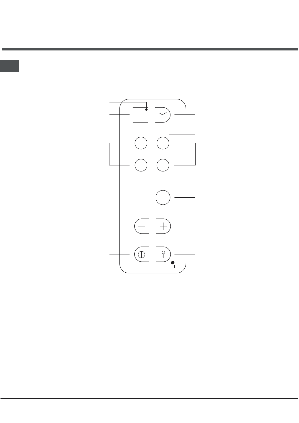
Control panel
Indicator light corresponding to the
PROGRAMMED COOKING ZONE *
PROGRAMMED COOKING
TIME indicator *
POWER (from 0 to 9) and
RESIDUAL HEAT indicators
COOKING ZONE
SELECTOR Keys
POWER (from 0 to 9) and
RESIDUAL HEAT indicators
15.
0
5.
00
Booster
TIMER CONTROL key for
COOKING TIME PROGRAMMING *
POWER (from 0 to 9) and
RESIDUAL HEAT indicators
ZONE SELECTION indicator
COOKING ZONE
SELECTOR Keys
POWER (from 0 to 9) and
RESIDUAL HEAT indicators
BOOSTER * Key
POWER DECREASE Key
ON/OFF Key
POWER INCREASE Key
Controls LOCK Key
LOCK indicator light
Only available on certain models.
*
4
Page 5

HOBS ET 6004 ET 6124 ET 7424
Cooking zones Power (in W) Power (in W) Power (in W)
Back Right (BR)
Front Right (FR)
Front Left (FL)
Back Left (BL)
I 1800
I 1200
I 1800
I 1200
ID 1800 – B 3000*
I 1200 – 600 if BR*
I 1800
I 1200
I 2400 – B 3000*
I 1200 – 600 if BR*
IO 1200/2400 – B 3000*
I 1200 – 600
Overall power 6000 6600 7200
è single induction zone
I
IO
è oval induction zone
B 3000* è the zone can be boosted to 3000 W
600 if BR* è the power of the cooking zone is reduced to 600 W as long as the BR zone is boosted
(for example)
GB
Cooking zone description
Induction is the fastest cooking method available.
Unlike traditional cooking zones, the induction zone
does not heat up the glass surface. The pan itself is
the heating element: the pan evenly transfers heat to
its contents as long as it is made of ferromagnetic
material.
Each zone is controlled:
by a selector key whose silk screen printing
reproduces the cooking zone drawing,
and by a power adjustment set comprising two
parts (+,-).
As long as the temperature of the cooking zones
remains above 60°C, even after use,
heat indicators stay onheat indicators stay on
heat indicators stay on (the power display
heat indicators stay onheat indicators stay on
indicates H) to prevent the risk of burns.
The table below features information on how to use
the zones to their full potential.
Power Type of dish
1 Melted butter or chocolate
2
3
4 Preparation of creams and sauces
5 Cooking stews, blanquette, desserts
6 Cooking pasta and rice
7
8
9 Fried food
Reheating liquids
Sealing meat, fish, omelettes
the residualthe residual
the residual
the residualthe residual
5
Page 6

Start-up and use
GB
When you connect the hob to the power supply, a
beep will sound after a few seconds: you can now
turn the hob on.
Turning on the hob
Press key for 3 seconds to turn the hob on.
Cooking zone control
Each cooking zone is operated by a control key and
by a power adjustment set (+ and -).
0
5.
00
Turning on a cooking zone
To turn a cooking zone on, press the
corresponding control key and set the desired
heating power (from 0 to 9) using the
keys.
To set the maximum power directly (9), press key
--
- briefly.
--
++
+ and
++
--
-
--
Controls lock
When the hob is in use, you can lock the controls to
avoid any accidental changes to the settings (by
children or when cleaning, for example).
Just press the
key lights up and
To change the power level setting or stop cooking,
the controls have to be unlocked: press the
the indicator light turns off and
unlockedunlocked
unlocked.
unlockedunlocked
To access the setting of a cooking zone again,
select the zone by pressing the corresponding
control key.
Cooking time programming
you may programme all the cooking zones
simultaneously for a maximum cooking time of 99
minutes.
Proceed as follows:
select the cooking zone by pressing the
corresponding control key,
set the desired heating power using the + and -
keys,
press the programming key
set the desired cooking time using the + and -
keys,
confirm the programming by pressing the
again.
key, the indicator light next to the
the controls are lockedthe controls are locked
the controls are locked.
the controls are lockedthe controls are locked
key,
the controls arethe controls are
the controls are
the controls arethe controls are
,
key
Turning off the hob
Press the key; the appliance has been turned off.
If you have locked the hob controls (see paragraph
below), the same will still be locked when you turn
the hob back on. Unlock the controls in order to
operate the cooking zones.
The booster
To speed up the rise in temperature of the cooking
zones (see cooking zone table on the previous
page), press the
The power display will indicate
function comes to an automatic stop after 4 minutes.
When the booster function is on, certain cooking
zones (see the cooking zone table on the previous
page) are limited to a maximum power of 600W.
Booster
key.
PP
P. The booster
PP
The countdown begins immediately.
The end of programmed cooking is signalled by a
beep (one minute long) and the cooking zone is
turned off.
6
Page 7
The safety devices
Pan recognition
Each induction cooking zone is fitted with a pan
recognition device. The cooking zone only provides
heat in the presence of a pan which is suitable for
the cooking zone.
A blinking pan recognition indicator could signal:
that the pan is made of unsuitable material, which
is not ferromagnetic,
that the diameter of the pan is too small,
that the pan has been removed.
Always match the
of the cooking zones.of the cooking zones.
of the cooking zones.
of the cooking zones.of the cooking zones.
Warning: oval cooking zones
Oval cooking zones can only be boosted if the full
oval is enabled.
Do not place two small saucepans on oval cooking
zones.
diameter of the pan with thatdiameter of the pan with that
diameter of the pan with that
diameter of the pan with thatdiameter of the pan with that
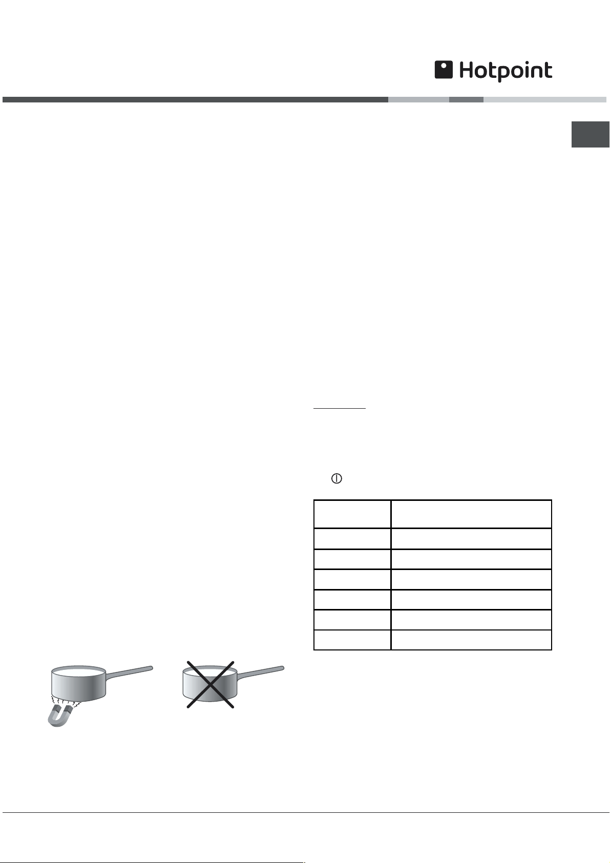
What cookware to use
Given that induction only exists when the magnetic
field is sealed by a metallic recipient, the pan stops
being heated as soon as it is taken off the cooking
zone.
Use cookware made of material which is
compatible with induction (ferromagnetic
material).
Cast iron, enamelled steel or special induction
stainless steel saucepans are ideal.
Copper, ceramic, earthenware, glass, terracotta,
aluminium and non magnetic stainless steel
cookware is incompatible with induction cooking.
The easiest way to find out whether the pan is
suitable is with a magnet. If the magnet is
attracted by the pan bottom and stays stuck to the
same, the pan is made of ferromagnetic material
and can be used on your induction hob.
We recommend you use pans with a very flat and
thick bottom and avoid at all costs all cookware
with irregular rough bases which could scratch the
glass surface.
SUITABLE
UNSUITABLE
Acoustic signal
Anomalies such as:
an object (such as a saucepan or a lid, etc.)
placed for more than 10 seconds on the control
zone,
boiled-over liquids or food spilled on the control
zone,
prolonged pressure on a key,...could cause a
beep to sound and the hob to turn off.
To stop the beep from sounding, remove the cause
of the malfunction.
To use the hob, turn it back on and re-select the
cooking zone(s) you wish to use. Set the desired
heating power.
Safety cut out
Your appliance is fitted with a safety cut out which
intervenes after a certain amount of time (see table)
depending on the power setting. When the safety
cut out has intervened, the power display indicates
0.
for example: the back right cooking zone is set to 5
and the front left zone is set to 2. The back right
zone will turn off after 4 hours of operation and the
front left zone will turn off after 6 hours of operation.
To unlock the controls, turn the hob off by pressing
the
key.
Power level Maximum duration of operation
1-2 10 hours
3 5 hours
4 4 hours
5-6 3 hours
7-8 2 hours
9 1 hour
GB
*
Enamelled steel
Special stainless steel
Cast iron
Aluminium, Glass, Earthenware,
Ceramic, non magnetic Stainless steel
Copper,
Overheating protection device
Should your appliances electronic components
overheat, the hob will turn off automatically and a
will come up on the power level display.
The letter will disappear as soon as the temperature
drops back down to an acceptable level.
7
Page 8

Precautions and tips
GB
This appliance has been designed and
manufactured in compliance with international safety
standards. The following warnings are provided for
safety reasons and must be read carefully.
Practical advice on using the appliance
To obtain the best results from your hob:
Use flat-bottomed pans to ensure that they adhere
to the cooking zone perfectly.
Always use pans with a diameter that is large
enough to cover the hotplate fully, in order to use
all the available heat.
Make sure that the bottom of the cookware is
always dry and clean to guarantee correct
adherence and durability, not only for the cooking
zones but also for the cookware itself.
Avoid using the same cookware that is used on
gas burners: the heat concentration on gas
burners may have warped the base of the pan,
causing it not to adhere to the surface correctly.
Never leave a cooking zone on without cookware
placed on it because it heats up and rapidly
reaches the maximum level, which could damage
the heating elements.
General safety
The appliance should not be operated by people
(including children) with reduced physical,
sensory or mental capacities, by inexperienced
individuals or by anyone who is not familiar with
the product. These individuals should, at the very
least, be supervised by someone who assumes
responsibility for their safety or receive
preliminary instructions relating to the operation of
the appliance.
The appliance was designed for domestic use
inside the home and is not intended for
commercial or industrial use.
The appliance must not be installed outdoors,
even in covered areas. It is extremely dangerous
to leave the appliance exposed to rain and
storms.
Do not touch the appliance with bare feet or with
wet or damp hands and feet.
The appliance must be used by adults only for the
preparation of food, in accordance with the
instructions provided in this booklet. Do not use
the hob as a worktop or chopping board.
The glass ceramic hob is resistant to mechanical
shocks, but it may crack (or even break) if hit with
a sharp object such as a tool. If this happens,
disconnect the appliance from the electricity
mains immediately and contact a Service Centre.
If the surface of the hob is cracked, switch off the
appliance to prevent electric shocks from occurring.
Ensure that power supply cables of other
electrical appliances do not come into contact
with the hot parts of the hob.
Remember that the cooking zones remain relatively
hot for at least thirty minutes after they have been
switched off. An indicator light provides a warning
when residual heat is present (see Start-up and use).
Keep any object which could melt away from the
hob, for example plastic and aluminium objects,
or products with a high sugar content. Be
especially careful when using plastic film and
aluminium foil or packaging:
if placed on surfaces that are still hot, they may
cause serious damage to the hob.
Always make sure that pan handles are turned
towards the centre of the hob in order to avoid
accidental burns.
When unplugging the appliance, always pull the
plug from the mains socket; do not pull on the
cable.
Never perform any cleaning or maintenance work
without having disconnected the appliance from
the electricity mains.
Do not place metal objects (knives, spoons, pan lids,
etc.) on the hob as they may become hot.
For the attention of wearers of pacemakers or
other active implants:
The hob complies with all current standards on
electromagnetic interference.
Your induction hob is therefore perfectly in
keeping with legal requirements (89/336/CEE
directives). It is designed not to create
interference on any other electrical apparatus
being used on condition that the apparatus in
question also complies with this legislation.
Your induction hob generates short-range
magnetic fields.
To avoid any interference between your induction
hob and a pacemaker, the latter must be
designed to comply with relevant regulations.
In this respect, we can only guarantee our own
product conformity. Please consult the pacemaker
manufacturer or your doctor concerning its
conformity or any possible incompatibility.
8
Page 9

Care and maintenance
Switching the appliance off
Disconnect your appliance from the electricity
supply before carrying out any work on it.
Cleaning the appliance
Do not use abrasive or corrosive detergents (for
example, products in spray cans for cleaning
barbecues and ovens), stain removers, anti-rust
products, powder detergents or sponges with
abrasive surfaces: these may scratch the surface
beyond repair.
Never use steam cleaners or pressure cleaners on
the appliance.
It is usually sufficient simply to wash the hob
using a damp sponge and dry it with absorbent
kitchen roll.
If the hob is particularly dirty, rub it with a special
glass ceramic cleaning product, then rinse well
and dry thoroughly.
Food residue and dirt can be removed using a
special scraper. Do this as soon as possible, do
not wait for the hob to cool down in order to avoid
incrustations. For excellent results, use a special
stainless steel wool pad for vitroceramic glass
cleaning soaked in soapy water.
Stainless steel frame *
Stainless steel can be marked by hard water which
has been left on the surface for a long time, or by
cleaning products containing phosphorus.
After cleaning, it is advisable to rinse the surface
well and dry it thoroughly. If water is spilt on the
surface, dry it quickly and thoroughly.
Some hobs have an aluminium frame which is
similar to stainless steel. Do not use any cleaning or
degreasing products which are not suitable for use
with aluminium.
Disassembling the hob
If it is necessary to disassemble the hob:
1. Loosen the screws fixing the alignment springs on
each side.
2. Loosen the screws holding the fixing hooks in
each corner.
3. Take the hob out of its installation cavity.
Do not attempt to repair the appliance yourself. If
the appliance breaks down, contact a Service
Centre.
GB
If any plastic or sugary substances are
accidentally melted on the hob, remove them
immediately with the scraper, while the surface is
still hot.
Once it is clean, the hob may be treated with a
special protective maintenance product: the
invisible film left by this product protects the
surface from drips during cooking. This
maintenance should be carried out while the
appliance is warm (not hot) or cold.
Always remember to rinse the appliance well with
clean water and dry it thoroughly: residues can
become encrusted during subsequent cooking
processes.
Only available on certain models.
*
9
Page 10

GB
After Sales Service
"No company is better positioned to offer an after sales service on a
Hotpoint appliance than us - the manufacturer"
As part of our commitment to you, all Hotpoint appliances have the added benefit of a fully inclusive parts and
labour guarantee for the first 12 months. In addition to this you also have the advantage of
replacement parts for the first 5 yearsreplacement parts for the first 5 years
replacement parts for the first 5 years when fitted by a Hotpoint
replacement parts for the first 5 yearsreplacement parts for the first 5 years
engineer. When the 12 months parts and labour guarantee expires we offer the following after sales service
options:
Repair Service and Information Help Desk
UK: 08709 066066
www.theservicecentre.co.uk
Republic of Ireland: 1850 302 200
Note: Our operators will require the Model number and the Serial number of your appliance
Available 364 days a year with a fast, effective and value for money service. We have the largest white goods
repair service in the UK with over 1200 of our own fully trained engineers. All repairs include a parts and labour
guarantee for 12 months from the date of the repair.
If you require any information or have any questions about your appliance, our operators are on hand with help
and advice.
All this ensures that you will receive the best available after sales service possible.
freefree
free
freefree
Extended Warranties
UK: 08709 088 088
www.theservicecentre.co.uk
Republic of Ireland: 1850 502 200
Whether you have just one or a number of Hotpoint appliances in your kitchen, we offer two service cover plans
to give you total peace of mind.
● Repair Protection Plan - FREE service repairs for a single Hotpoint appliance during the period
of cover.
● Kitchen Cover - FREE service repairs for all your Hotpoint appliances less than 8
years old.
Genuine Parts and AccessoriesGenuine Parts and Accessories
Genuine Parts and AccessoriesUK: 08709 077 077
Genuine Parts and AccessoriesGenuine Parts and Accessories
www.theservicecentre.co.uk
Republic of Ireland: (01) 842 6836
A wide range of genuine parts and accessories are available from our hotline or through our web site.
Genuine parts and accessories, extended warranties and service repairs are all
available on our web-site at:
10
www.theservicecentre.co.uk
Page 11

GuaranteeGuarantee
Guarantee
GuaranteeGuarantee
"Satisfaction guaranteed or your money back""Satisfaction guaranteed or your money back"
"Satisfaction guaranteed or your money back"
"Satisfaction guaranteed or your money back""Satisfaction guaranteed or your money back"
GB
We give you a unique 'satisfaction guaranteed' promise -
purchased your Hotpoint appliance. If there is a technical problem simply call Hotpoint Repair
service or visit our web-site at
an engineer to call. If the technical problem is not resolved under this guarantee,
your machine or, if you prefer, give you your money back.your machine or, if you prefer, give you your money back.
your machine or, if you prefer, give you your money back.
your machine or, if you prefer, give you your money back.your machine or, if you prefer, give you your money back.
All Hotpoint appliances carry a fully inclusive 12 month parts and labour guarantee as well as free
replacement parts for the first 5 years (except microwaves, selected integrated appliances and
cooker hoods, which have a one year guarantee) provided that they are fitted by a Hotpoint engineer.
Guarantee terms and conditionsGuarantee terms and conditions
Guarantee terms and conditions
Guarantee terms and conditionsGuarantee terms and conditions
Your guarantee is only applicable in the United Kingdom or Republic of Ireland and is subject to the
following provisions that your appliance:
● Has been installed and used correctly in accordance with this instruction booklet.
● Has been used solely for domestic purposes and is located on domestic premises (ie. not for
commercial or trade use).
● Has been properly connected to a suitable electrical supply voltage as stated on the appliance
rating plate.
● Has not been subject to misuse, accident, modified or repaired by anyone other than one of our
own service engineers.
www.theservicecentre.co.uk and where necessary, we will arrange for
valid for 90 daysvalid for 90 days
valid for 90 days - after you have
valid for 90 daysvalid for 90 days
we will replacewe will replace
we will replace
we will replacewe will replace
For pre purchase information on any other Hotpoint product call: 08701 50 60 70
or visit: www.hotpoint.co.uk
Recycling & Disposal Information Recycling & Disposal Information
Recycling & Disposal Information
Recycling & Disposal Information Recycling & Disposal Information
As part of Hotpoint's continued commitment to helping the environment, Hotpoint reserves the right to
use quality recycled components to keep down customer costs and minimise material wastage.
Please dispose of packaging and old appliances carefully.
To minimise risk of injury to children, remove the door, plug and cut mains cable off flush with the
appliance. Dispose of these parts separately to ensure that the appliance can no longer be plugged
into a mains socket, and the door cannot be locked shut.
11
Page 12

GB
09/2007 - 195043663.05
XEROX BUSINESS SERVICES
Key Contacts
After Sales Service
Over 1200 trained specialists, directly employed by us, ensure that you can have complete
confidence in both the appliances and services we offer.
Repair Service and Information DeskRepair Service and Information Desk
Repair Service and Information Desk
Repair Service and Information DeskRepair Service and Information Desk
UK: 08709 066 066
(Open 8 to 8 Mon - Fri, 8 to 6 Sat, 10 to 4 Sun & Bank Holidays)
www.theservicecentre.co.uk
Republic of Ireland: 1850 302 200
Note: Our operators will require the following information:
Model number:
Serial number:
Extended WarrantiesExtended Warranties
Extended Warranties
Extended WarrantiesExtended Warranties
UK: 08709 088 088
(Open 8 to 8 Mon - Sun)
www.theservicecentre.co.uk
Republic of Ireland: 1850 502 200
Genuine Parts and AccessoriesGenuine Parts and Accessories
Genuine Parts and Accessories
Genuine Parts and AccessoriesGenuine Parts and Accessories
UK: 08709 077 077
(Open 8-30 to 5-30 Mon - Fri & 9 to 12 Sat)
www.theservicecentre.co.uk
Republic of Ireland: (01) 842 6836
12
Indesit Company UK Ltd. Morley Way, Peterborough, PE2 9JB.
 Loading...