

Page 1

Machine Overview........................................................................................................... 8-3
Power.............................................................................................................................. 8-5
User Interface..................................................................................................................8-10
Machine Run Control ...................................................................................................... 8-12
Single Pass Document Handler (SPDH)......................................................................... 8-18
Fusing and Copy Transportation..................................................................................... 8-33
Low Capacity Stapler Stacker (2K LCSS)....................................................................... 8-47
LVF BM ........................................................................................................................... 8-56
High Volume Finisher (HVF)........................................................................................... 8-75
Fax .................................................................................................................................. 8-98
Main Drive Module .......................................................................................................... 8-98
Scanner Module.............................................................................................................. 8-102
LED Print Head (LPH)..................................................................................................... 8-108
Paper Supply................................................................................................................... 8-111
Paper Transportation and Registration ........................................................................... 8-136
Xerographics................................................................................................................... 8-140
8 Principles of Operation
Launch Issue
Xerox® AltaLink® B8090 Family Multifunction Printe r
April 2017
8-1
Principles of Operation
Page 2

Principles of Operation
April 2017
8-2
Launch Issue
Xerox® AltaLink® B8090 Family Multifunction Printer
Page 3

Machine Overview
Configuration Options
The Xerox® AltaLink® B8090 Family is available as a basic machine with trays 1, 2, 3, 4 and 5
(bypass tray) plus an optional tray 6 (external paper feede r platform - PFP). Five machine
speeds are available in two variants.
First machine variant:
• AltaLink® B8045 - 45 ppm
• AltaLink® B8055 - 55 ppm
Second machine variant:
• AltaLink® B8065 - 65 ppm
• AltaLink® B8075 - 75 ppm
• AltaLink® B8090 - 90 ppm
Refer to Overview within the Main Drive Module section for details of the two variants and how
the speeds are achieved.
General
For the space requirements, environment range and the print out time. Refer to:
• GP 21 Installation Space Requirements.
• GP 23 Environmental Data.
• GP 25 First Copy / Print Out Time and Power On / Off Time.
Paper Supply and Paper Handling Options
• 200 sheet single pass document handler (SPDH).
• Two 500 sheet paper trays (designated tray 1 and tray 2).
• 3600 sheet high capacity feeder (designated trays 3 and 4).
• 100 sheet bypass tray (designated tray 5).
• Optional 3300 sheet high capacity feeder (designated tray 6).
Output Options
• A horizontal transport is also installed when a finisher is fitted.
• Office finisher (2K LCSS). See 2K LCSS General Description.
• Office finisher with booklet maker (LVF BM). See LVF BM General Description.
• High volume finisher (HVF). See HVF General Description.
• High volume finisher with booklet maker (HVF BM). See Booklet Maker Module.
• Post print inserter (PPI) used with an HVF BM. See Tray 7 Inserter .
• Tri-folder used with an HVF and HVF BM. See Tri-Folder.
Table 1 describes finisher and paper handling options for each speed variant.
Table 1 Paper handling and finisher options
Tray 6
(PFP)
45ppm Yes Centre tray or horizontal transport Yes Yes No
55ppm Yes Centre tray or horizontal transport Yes Yes No
65ppm Yes Centre tray or horizontal transport Yes Yes Yes
75ppm Yes Centre tray or horizontal transport Yes Yes Yes
90ppm Yes Horizontal transport only No No Yes
Centre tray or horizontal
transport
2K LCSS LVF BM
HVF BM Tri
folder/ PPI
NOTE: If an incompatible fin isher is installed the s tatus line will displa y Status Code 12.765
Incompatible/unknown finisher detec ted .
Registration
The AltaLink® B8090F are centre registered multifunction printers as follows:
• Side 1 scanning:
– Centre registered document guides are used when the document is scanned
through the single pass document handler.
– Edge registered when the document is manually placed on the platen glass.
• Side 2 scanning - centr e registered document guides ar e used when the document is
scanned through the single pass document handler.
• All paper trays use centre registered paper guides.
• The paper is not actively registered along the paper path.
•2K LCSS:
– Stacking - centred by tampers
– Stapling - centred by tampers
– Hole punching - no active registration
• LVF BM:
– Stacking - centred by tampers
– Stapling - centred by tampers
– Hole punching - no active registration
– Booklet making - centred by tampers
•HVF BM:
– Stacking - centred by tampers
– Stapling - centred by tampers
– Hole punching - centred by activ e re gistrat ion. A s ensor d etects th e to p edge of the
paper. The control board co mmands a motor to move the punch into the d esired
position.
– Booklet making - centred by tampers
Accessories and Kits
• Workshelf.
• 50 sheet convenience stapler.
• 2 hole punch kit.
• Legal 2 hole punch kit.
• 3 hole punch kit.
• 4 hole punch kit.
• Swedish 4 hole punch kit.
• 1 Line Fax kit.
• 2 Line Fax kit.
• Scan to PC desktop SE - standard.
• Scan to PC desktop SE - professional.
• Nationalization kits.
• Foreign device interface kit.
• Tray 2/4 lock kit.
• Envelope tray feed kit.
Launch Issue
Xerox® AltaLink® B8090 Family Multifunction Printe r
April 2017
8-3
Principles of Operation
Page 4
• Unicode international printing kit.
• Secure access kit.
• Common access card.
• McAfee Integrity Control enablement kit.
• XPS enablement kit.
• Wireless print kit.
• Smartcard kit.
• User interface external keyboard.
Consumables and Billing
There are three types of consumables:
• Print cartridge
• Toner cartridge
• Fuser
for full details of consumables refer to GP 39. For full details of billing and service plans refer to
GP 9.
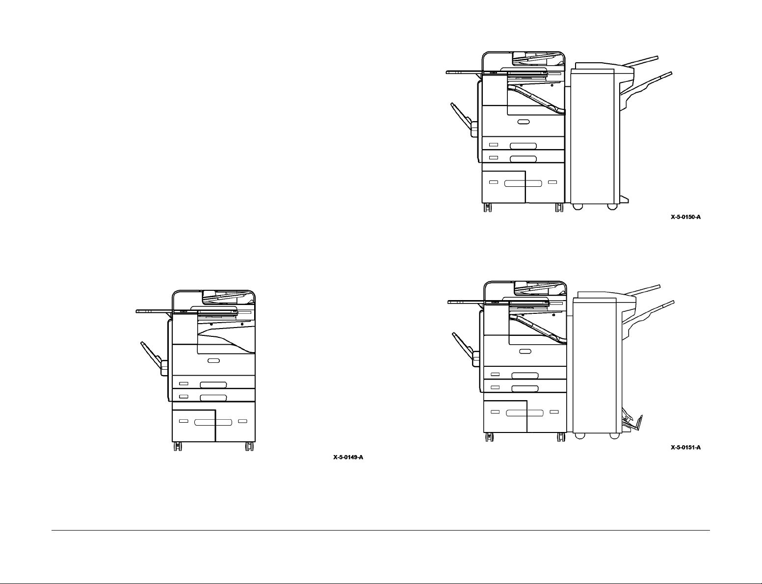
Machine Identificatio n
• Figure 1 AltaLink® B8075 with centre output tray and workshelf.
• Figure 2 AltaLink® B8055 with 2K LCSS.
• Figure 3 AltaLink® B8065/B8075 with LVF BM.
• Figure 4 AltaLink® B8090 with tray 6, HVF BM, inserter and tri folder.
Figure 2 Machine with 2K LCSS
Figure 1 With centre output tray and workshelf
Principles of Operation
April 2017
8-4
Figure 3 Machine with LVF BM
Launch Issue
Xerox® AltaLink® B8090 Family Multifunction Printer
Page 5
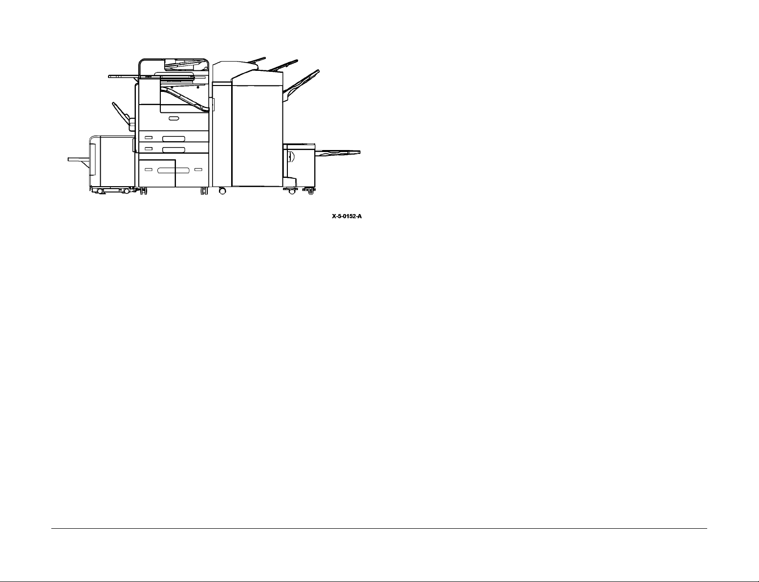
Figure 4 With tray 6, HVF BM, tray 7, tri-folder
Power
Power Generation and Distribution
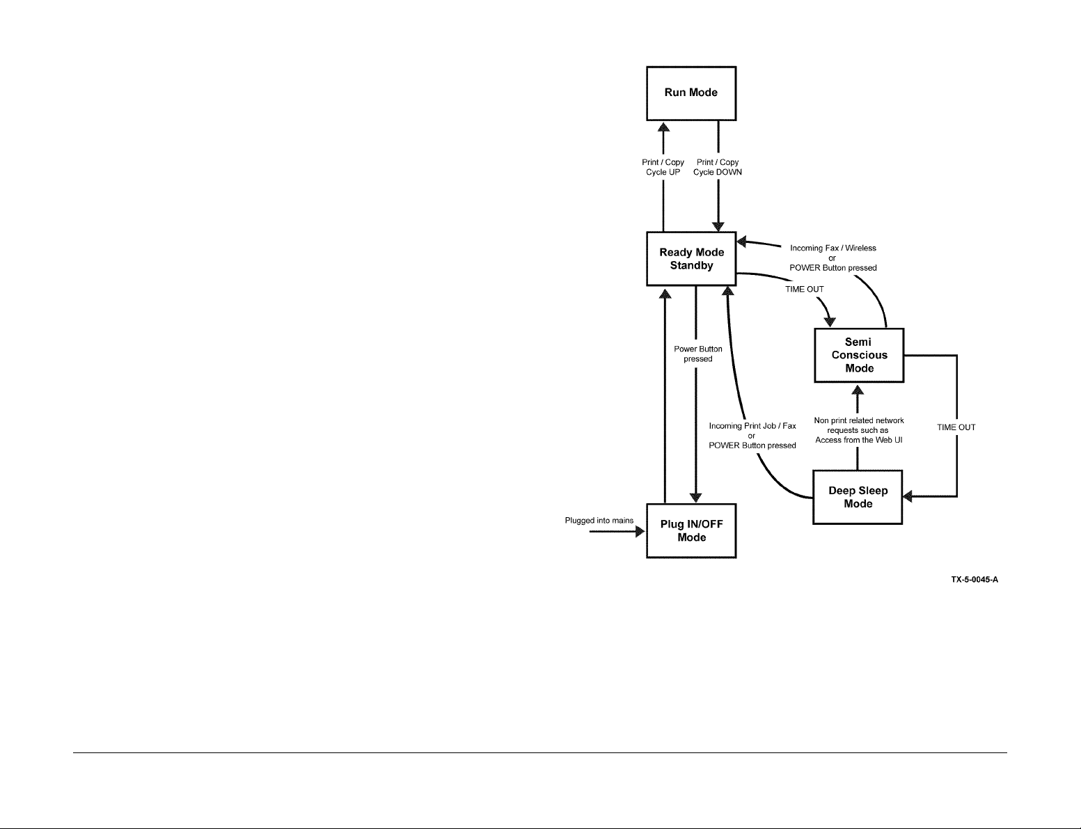
System Operating Modes
In order to comply with the environmental agency requirements the system must have different
power states called o perating modes. Each mode has different levels of power consumption
and system functionality. See also GP 22 Electrical Power Requirements.
Plug-in/Off Mode
This is not an operati ng mode. P lug in/off i s the condi tion of the machine when power is connected but the machine is powered down. When the power butt on is pressed to shut down
(and confirmed) this is the condition of the machine.
This is the lowest power state that the mac hi ne c an ent er. On ly the LV PS and po wer man agement circuitry on the SBC is active.
The only method that can be used to power the machine on, in this mod e, is to press the UI
power button.
Standby/Ready Mode
Also referred to as Level 1 power (Blue Angel RAL-UZ 171 specifications).
This is the n o rma l op er at i ng co nd i ti o n of th e m ac hi n e wh en it is r ea dy fo r wa lk-up copying . Th e
UI is active and illuminated in this mode. This is the cond ition of the machine wh ile a user is
programming a job via the UI or performing any other UI activity.
In this mode the system is ready to print/copy/fax with little or no delay in hard copy output. The
system has full fun ctionality when in this mode, is capable of meeting FCO T (first copy out
time) and FPOT (first print out time) requirements when in this mode only.
Launch Issue
Xerox® AltaLink® B8090 Family Multifunction Printe r
Run Mode
This is the condition of the machin e when it is acti vely print ing a job. The machine enters this
mode when a user selec ts the final command to run a co py jo b. T he mac hi ne ente rs th is st ate
when it executes a print job via the network.
In this mode the system is in the pr ocess of marking images and/or collating in an output
device.
Sleep States
NOTE: The user will not be able to tell the di fference semi conscious state and deep sle ep
state. Visually the machine appears the same.
Semi Conscious Mode
The machine enters semi conscious mode after a period of inactivity after the most recent print
job or copy job. In semi-co ns cious mo de th e UI is i nactiv e a nd th e power button is illuminated.
The delay time is preset but is adjustable by the customer in the range 0 to 30 minutes.
Semi conscious mode allows the system to perform the following limited functions:
• Access to the remote control panel via the web UI.
April 2017
8-5
Principles of Operation
Page 6
• Wireless printing (if installed)
• All non print related network requ ests (including HDD a ccess), such as access from the
web UI.
NOTE: If Wake on USB is enabled the sys tem remai ns in semi conscious mode and does not
enter deep sleep mode.
Deep Sleep Mode
Also referred to as S3 power (Blue Angel RAL-UZ 171 specifications).
Recovery from this mod e to standby/read y is from either pressing the UI powe r button or an
incoming fax and or print job. The machine does not wake from sleep mode upon insertion of a
USB drive.
• Only standby power is available. SBC network control, power management.
• The system is able to wake up for network printing or incoming fax (if installed).
• The system is able to wake up when the user presses the UI power button.
• The system will be ‘rea dy to scan’ from any wak e up event i n less than 1 5 seconds w ith
UI available within 1 second.
Auto Power Off
Enables the system to switch off aft er a specified time in deep sleep mode via an adjustab le
timeout that is acc essed using tools or in the Web UI. The default is ‘disabled’. Once the
machine has switched o ff it can be switched on via the po wer switch on the UI. When the
machine has powered down auto matically it is in the same stat e as it would be after fir st con
necting mains power.
Operating Mode Transitions
Warm Up
In this condition the system is booting up from plug in/off mode or recovering from sleep mode.
The system will be ‘ready to scan’ with in 135 seconds from power up. Product perfor mance
specification warm up times quoted are from ‘pow er save’ to ‘system ready’ (ac ceptance of
scan, print or fax input) . Fus er war m up ti me wi ll v ar y de pen ding on li ne v ol tage , amb ie nt tem
perature and time since machine was last switched on, etc.
-
-
Figure 1 shows the system operating modes and the associated transitions from mode to
mode that are required to ensure the s ystem meets all envir onmental a gency energy require
ments.
Principles of Operation
April 2017
-
Figure 1 Operating mode state transition diagram
Launch Issue
8-6
Xerox® AltaLink® B8090 Family Multifunction Printer
Page 7

LVPS Functions
The LVPS is split into the following main functions:
• Provides a +5V stand-b y supply to the powe r management c ontrol circuitry on th e SBC
PWB. In plug-in off mode thi s consumes le ss than 0.5W AC to enable m onitoring for the
power button.
• Switches on and off AC power to the output device outlet, and +5V and +24V main as
directed by the SBC PWB.
• Provides +5V and +24V to power the SBC PWB in ready, and run modes.
• Provides main +5V interlocked power to the IOT PWB during normal operation.
• Provides main +24V non-interlocked power to the IOT PWB during normal operation.
• Provides power to the fuser using a combination of cycle switching and phase control patterns. Firmware within the LVPS us es look up ta bles based on power demand ed by the
IOT software and the line voltage detected at the LVPS input.
There are two types of LVPS (PL 1.10 Item 1):
• A single 12 amp LVPS is used for the A ltaLin k® B8045/B 8055 1 10V or 23 0V and for the
AltaLink® B8065/B8075/B8090 230V.
• A 16 amp LVPS is used for the A ltaLink ® B806 5/B807 5/B809 0 110V. T his LV PS h as an
IEC320 C20 type mains connector.
Control Lines and Operating Modes
This section describe s the co ntrol line s between the SBC PW B, IOT P WB and LV PS used to
control the operating modes by the switching of AC and DC supplies in the system.
Interlock Switches
When the interlock sw i tches ar e clos ed an d th e I OT C Fail s ig nal is lo w, th e L VP S ena ble s the
+24V INTLK, and enables fuser power.
The front door interlock sw itch, S01 -300, and the le ft door interl ock switch , S01-305, are connected in series to the LVPS.
IOT-LVPS Interface Hotlines
POWER_FAIL
The IOTC_Fail signal is an early warning of an imminent loss of AC power.
LVPS to IOT Comms Line
The LVPS communicates with the IOT to signal power availability.
SBC-LVPS interface hotlines
PS_ON
When this signal is e nabled (low), the LVPS enables main +5V, +24V and +24 Interlocked
power.
Entering/Exiting Power Modes
From Plug In/Off Mode
+5VSB power is act ive during all modes as soon as the mach ine is plugged in to a powered
wall socket to monitor the UI power button.
From plug in/off mode to ready: User presses the UI power button which cause s the power
management circuitry on the SBC PWB to enable th e PS_ON signal to switch on the main
LVPS outputs. The system can then boot up and perform initialisation and the warm up
sequence.
From Ready (Ready to Scan) Mode:
All power supply outputs are ‘on’ in this mode. A user pressing the UI power button invokes the
pop-up: ‘power down option s, quick restart, enter power saver m ode or power off’ selection
screen on the UI.
From ready (ready to scan) mo de to pl ug-in off m ode: If “ powe r down” is s elec ted, a fter c onfi rmation from all modules is ac cepted, the SBC PW B disables the P S_ON hotline. This in turn,
removes all AC and DC outpu ts, except +5VSB. An additional met hod to achieve this is to
keep the power button pressed for 5 seconds which overrides software.
From ready (ready to scan) mode to sleep mode: If “enter sleep mode” is selected, after confirmation from all modules is accepted , the PS_ON signal is disabled whic h removes the main
DC outputs from the LVPS as well as AC power to the finisher. +5VSB remains on in this
mode.
From ready (ready to scan) mode to quick restart: If quick restart is selected, the SB C PWB
and IOT PWB perfor m soft resets and re-initi alize the system as per s witch on from plug in
mode.
From Deep Sleep Mode or Semi Conscious Mode:
+5VSB output is activ e in thi s mod e. Only th e S B C P WB , f ax mo dule a nd the UI power button
are active in this mode.
From sleep mode to s tand-by mode via wake up from incoming print job: T he SBC PWB is
capable of waking the system from sleep m ode on receipt of any i ncoming job that re quires
marking. The SBC PWB enables the PS_ON signal, which enables all main power.
From sleep mode to stand-by mode via wake up from incoming fax job: The fax modu le is
capable of waking the system from slee p mode on receipt of an incoming job that requires
marking. The PME signal is used to ind icate to the SB C PWB that the wake up call ha s been
initiated. The SBC PWB enables the PS_ON signal, which enables all main power.
From sleep mode to stand-by mode via wake up from user intervention at UI: The UI is capable
of waking the system from sleep mode by pressing the power button. The On Off Button signal
is detected by the SBC PWB, which enables the PS_ON signal, which enables all main power.
Launch Issue
Xerox® AltaLink® B8090 Family Multifunction Printe r
April 2017
8-7
Principles of Operation
Page 8

DC Power Distribution
Table 1 below shows how the power is distri buted from the LVPS to the rest of the su b-sys-
tems (excluding the AC distribution to the finisher and the fuser).
Table 1 LVPS DC power distribution
+24V
+24V
Module Description +5VSB +5V
Image output terminal controller (IOTC) yes yes yes
Single board controller (SBC) yes yes yes
Drives module yes
Other voltages are generate d and d is tribu ted by the SBC and IOT PWBs . Refe r to Tabl e 2 and
Table 3.
Table 2 SBC DC power distribution
Module Description +3.3V +5V +12V +24V
Fax module yes yes
LED Print head (LPH) yes
Scanner module yes yes yes yes
User interface (UI) yes
Hard disk drive (HDD) yes
Table 3 IOT PWB DC power distribution
Module Description +3.3V +5V
High voltage power supply (HVPS) yes
Paper feed module (PFM), tray 1 and 2 yes yes
High capacity feeder (HCF), tray 3 and tray 4 yes yes
Tray 6 yes yes
HCF transport motor yes
Left door yes yes
Tray 5 (bypass tray) yes
Bypass tray clutch yes
Horizontal transport yes yes
Drives Module yes
INTLK
+24V
INTLK
non
INTLK
+24V
non
INTLK
System Power On/Off Times
Refer to Table 4.
Table 4 System power on/off times
Power on
Power Timings
Power LED on UI flashes <2s N/A <41s N/A
First UI screen displayed N/A <4.5s N/A N/A
Services Home Screen
displayed
Ready to Scan (Fax, File
or E-mail send)
Ready to Scan (Cop y) (3) <135s (1) <15s (2) <176s (1) N/A
Ready to Mark <160s (1) <28s <201s (1) N/A
Power Off N/A N/A N/A <36s
Blue Angel recovery time
(45ppm) (4)
NOTE:
1. The time taken for a machine to power on, is dependent o n the numbe r and type of s ervices enabled on the de vice b eing evaluated . Th e val ues sho wn in the tabl e ass ume the
basic configuratio n as shipped from the facto ry. i.e. Copy; Print From; ID Copy; Serve r
Fax:. Additionally, automatic data integrity routines that can occur randomly after 20
power on events from a software alt -boot, can add up to 90 seconds to these ti mes.
Therefore measurement of power on times needs to be done shortly after an Alt-boot.
2. Recovery from sleep is dependent on which of two sleep modes the machine has
entered. Recovery from sleep can be considerably faster than the time shown .
3. Ready to Copy is indicated by the message “Ready to Scan” being displayed on the GUI.
4. Tested as per Blue Ange l RAL UZ-171 on 45ppm only. Higher speed machines have
higher limits hence this is critical path.
from off
<120s (1) <15s <161s (1) N/A
<135s (1) <15s (2) <176s (1) N/A
N/A <25.58s(4) N/A N/A
Sleep Recovery
(touch power
button)
Ready from
Restart
Power off from
Ready
Principles of Operation
April 2017
8-8
Launch Issue
Xerox® AltaLink® B8090 Family Multifunction Printer
Page 9

High Voltage Power Supply
The high voltage power supply generates the voltages used by the xerographics system.
The IOT PWB supplies 24V to the HVPS.
The IOT PWB sends the following control signals to the HVPS. Refer to Table 5.
Table 5 HVPS control signals
Signal Description
BCR AC PWM Pulse-width-modulation control line for activation and setting of the BCR AC
BCR DC PWM Pulse-width-modulation control line for activation and setting of the BCR DC
BCR CLOCK Control line for BCR frequency. Typical 1.6 kHz.
DB AC PWM Pulse-width-modulation control line for activation and setting of the DB AC
DB DC PWM Pulse-width-modulation control line for activation and setting of the DB DC
DB CLOCK Contr ol lin e for DB fre que ncy. Typi c al 9 kHz.
BTR CC PWM Pulse-width-modulation control line for activation and setting of the BTR pos-
BTR MODE Control line which disables the BTR constant current mode, and then
DTS ON Control line which enables the DTS negative voltage source.
The HVPS returns a BTR MON signa l to the IOT PW B . The vo lta ge is scal ed ac cor di ng to this
formula: BTR MON = 2.5 + (0.00045 x BTR Voltage). For example, BTR MON = 2.5 when BTR
voltage = 0.
current source.
voltage source.
current source.
voltage source.
itive current source.
enables the BTR negative constant voltage mode.
Based on the inputs, the HVPS supplies the following to the xerographics system:
• BCR (Bias Charge Roll) is the sum of the BCR AC and BCR DC sources.
• DB (Developer Bias) is the sum of the DB AC and DB DC sources.
• BTR (Bias Transfer Roll) is either the BTR CC or BTR CV source, depending on the state
of the BTR MODE input. Both sources are DC.
• DTS (DeTack Saw) is simply the DTS negative voltage source.
Launch Issue
Xerox® AltaLink® B8090 Family Multifunction Printe r
April 2017
Principles of Operation
8-9
Page 10
User Interface
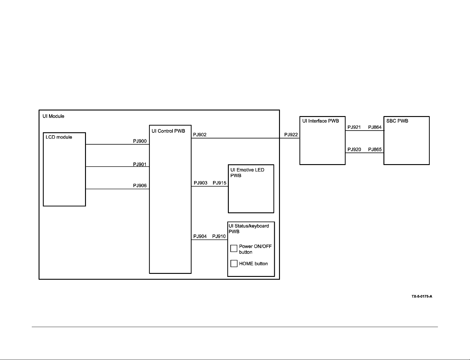
The UI module is ma de of four assemblies, the LCD module, the contr ol PWB, the emotive
LED PWB and the status/LED PWB, PL 2.10.
The UI includes the following features.
• A 10.1" LCD display and capacitive multi touch LCD screen.
• Emotive LED bar, an array of LED's for machine status indication.
• Machine power ON/OFF control with wh ite LED backlight for power sav er mode indication.
• Audio speaker.
• Near field communication (NFC) module.
The UI consists of 5 components, Figure 1.
1. LCD module (within the UI module).
2. UI control PWB (within the UI module).
3. UI status PWB (within the UI module).
4. UI emotive LED PWB (within the UI module).
5. UI interface PWB (mounted within machi ne frame) .
6. External keyboard (accessory).
Only the following components are accessible:
• UI module, PL 2.10 Item 1.
• UI interface PWB, PL 2.10 Item 15.
Principles of Operation
Figure 1 User interface components
April 2017
8-10
Launch Issue
Xerox® AltaLink® B8090 Family Multifunction Printer
Page 11

LCD Module
The LCD module comprises,
• a color TFT screen (Thin Film Transistor),
• embedded backlight,
• capacitive touch panel.
The cables are wired directl y into the LCD mod ule. All the LCD mo dule cable s connect to the
UI control PWB. PJ numbers are detailed on the UI control PWB.
Display video input for the TFT display is provided from the control PWB; four Pairs of LVDS
display data and one p ai r of c lo ck fr om the PS 862 2 de vice whi ch c onv erts di splay p or t da ta to
required LVDS data which is driven to the TFT display through buffer FIN1108.
UI Control PWB
The control board is the main board in the UI assembly which supplies power and the required
ON/OFF sequence for the TFT LCD module. Microcontroller MSP43 0F5510 provides PWM
drive for the emotive LED and au dio, required control signal s for power sequencing and I2C
bus for EEPROM access which stores EDID data. An RS-422 interface is used for communica
tion to the SBC.
The UI module provides an audi tory response that indicates machi ne statuses such as fault
conditions, authentica tio n, powe r s aver en try/e xi t a nd tou ch ton es. T h e UI c ont rol PWB stores
all the audio files and includes a speaker on the board for the audio output.
UI Emotive LED PWB
The emotive LED PWB contains 4 blue LE Ds and 4 amber LED s. The emo tiv e PW B also con tains the required biasing resistor and the mai n drive circu it is loca ted in the con tr ol PW B.
• PJ915 connects to the UI control PWB.
UI Interface PWB
The UI interface PWB, PL 2.10 Item 15, connects the UI control PWB to the rest of the
machine.
• PJ920 connects to the SBC PWB.
• PJ921 connects to the SBC PWB.
External Interface connectors/signal details
The SBC interface to th e main control PWB is via the UI interface board through an RJ150
connector for video and an 18 way DF11 connector for control and power signals. The connec
tor into the UI module from the UI interface board is via a 40 way FFC connector.
Grounding scheme
There is a common single digital ground. All the return c urrent is passed to the SBC via the
interface connector. There is no chassis ground for the UI module as it as made of plastic.
-
Connections on the UI control PWB
• PJ900 to the LCD module - 1024 x 600 color TFT
• PJ901 to the LCD module - capacitive touch panel
• PJ902 to the UI interface PWB
• PJ903 to the UI emotive LED PWB
• PJ904 to the UI status PWB
• PJ906 to the LCD module - LED backlight
UI Status/Keyboard PWB
The Status/keyboard PWB contains the machine power button and the home button.
• The power ON/OFF but ton is for system power ON/OFF an d features an array of white
LEDs as a back light driven direc tly from the SBC PWM signal. This LED is for pow er
saver indic ation.
• The Home button returns the syste m to the ho me screen. This signal i s mapped directly
to the SBC GPIO.
The UI module is provided with an NFC (near field communication) tag to enable printing functionality through NFC. The NFC antenn a and chi p are mo unte d on the UI sta tus PW B. A wh ite
light LED on the UI status PWB illuminates when the NFC is active.
NFC provides the RF interfa ce for contactless communic ation with an external read er/writer,
serial interface for contact communication with an external host, control logic for command pro
cessing and various con trols. It also consists of access restr iction of RF communication by
password. Supply voltage provided is 3.3 V.
• PJ910 connects to the UI control PWB.
Launch Issue
Xerox® AltaLink® B8090 Family Multifunction Printe r
April 2017
External keyboard (accessory)
A slide out keyboa rd, c on nec ted to a U SB po rt, c an be mou nted be neath the main UI modul e.
This keyboard can be used as an alternative to the touchscreen keyboard. (PL 2.10 Item 14)
-
Principles of Operation
8-11
Page 12
Machine Run Control
e
Overview
The Single Board Controller (SBC) PWB interfaces with the Image Output Terminal (IOT)
PWB, scanner, netw ork, fax, and the UI. Control of the subsystems is de legated to the IOT
PWB, or the PWBs within the subsystem, while the SBC maintains system level control.
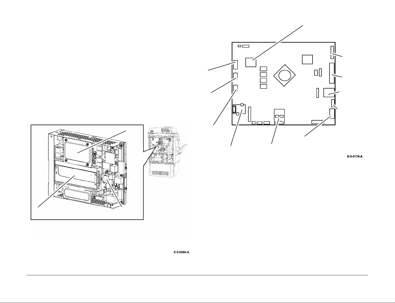
SBC Module Overview
The SBC module has different configuration options. When option al configurations are not
used, blanking plates are needed.
Backup battery
LED print
head
The SBC PWB supports existing optional PWB interfaces such as FDI, Common Interface Fax
(CIF) and PWS.
Refer to PL 3.22. The SBC PWB is contained in a c ha ss is. T h e S BC PW B c has sis c onsis ts of
a metal cage, interior bracke t, and top cover. The module co ntains the SBC PWB , HDD, and
optionally, the fax module and FDI PW B , alon g with mec hanic al pa rts and harnesses. Refer to
Figure 1 and Figure 2.
HDD
Fax PWB SBC PWB
Ethernet port
USB host
USB device
IIT power
SIM card slot
SBC Performance
The image path for this color s cann er brin gs the sc anner v ideo d irectly t o the S oftware Ima ge
Path (SWIP).
The SWIP is used as the main video controller for the high speed digital printer and multi function digital copier color applications. The device is controlled through a 32 bit, 66 MHz host PCI
bus. The Calypso SWIP scan im age processing (with JPEG), print image proces sing, image
data compression/decompression capability, rotation and merge engines, input data inter
faces, and image outp ut capab ility. I mage data may be sto red in either EPC or system memory.
SD card
Figure 2 SBC PWB
IIT video
User interfac
User Interface
power
-
Principles of Operation
Figure 1 SBC PWB module
The SBC PWB also contains a USB dev ice (singl e) and U SB host ( single and dual) por ts, as
well as a three-speed (10/100/1000) Ethernet port, a debug port, a SIM port to configure
machine speed and a For ei gn Devic e Int erfac e. T h e FD I P WB requi r es th e u se o f a s ep arate
cable from the bulkhead to the actual FDI PWB.
Backup Battery
The backup battery is used to suppl y power to the real- time c lo ck and the powe r mana gem ent
circuitry when the machine is not plugged in.
April 2017
8-12
Xerox® AltaLink® B8090 Family Multifunction Printer
Launch Issue
Page 13

SBC PWB Interfaces
The SBC PWB interfaces with:
• IOT PWB (including hotlines)
• User interface
• Image input terminal
• LED print head
• Portable workstation
•Network
•Fax
• External debug communication port.
The SBC PWB has provisions for the plug in items listed in Table 1.
Table 1 Plug in items
Standard Configurat ion Optional Configuration
SD Memory Card FDI
HDD Common Interface Fax
SIM Card
UI Interface
• The RS-422 (TX and RX only) at a baud rate of 480K.
• A USB host is connected to the SBC PWB USB port through an on-board connector.
• The SBC PWB provides +3.3V DC and +12V DC power to the UI.
• The SBC PWB is capable of waking up from the UI Wake up switch (Wake UP switch signal).
• The interface supports a low vol tage differential signal (LVDS) output to drive a color
LCD.
image Input T erminal
• The SBC PWB supplies +3.3V, +5V, +12V, and +24V DC to the scanner.
• The RS422 (RX and TX Only) at a baud rate up to 480K.
• The scanner PWB further connects to the SPDH PWB.
SD Memory Card
The SD card replaces the software module used on other products. The card will support these
functions:
•Boot ROM
•NVM
• MFD feature key
NOTE: These functions are not accessible by the customer.
SIM Card Interface
Provides a slot accessible to the user for configuring the machine.
A cryptomemory card ca n be plugged into a SIM c ard slot on the SBC PWB t o authenticate
machine features. The SBC will control this device via an I2C bus.
System Memory
System memory is 2GByte of DDR3 RAM. The chips are mounted directly to the SBC PWB.
Ethernet Base 10/100/1000T
• The Ethernet interface connects directly to the network.
• Is capable of waking up from sleep mode on detection of network traffic.
USB Interface
• The SBC PWB has 3 USB host ports and 1 USB device port. The USB host port 3 is connected to the UI USB port through an on-board connector.
• The Host ports support potential host functions, such as flash-drive plugability, biometrics
(security), USB printing, software upgrade and other user-identification devices, etc.
There are 2 ports acces sible through t he SBC tra y front and 1 p ort accessi ble within the
SBC tray for front of machine (UI) access.
NOTE: The USB Host power for attached peripherals is limited to 2.5W per port.
• The device port suppo rts functions such as fi eld service PWS (Po rtable Work Stations )
connection, and direct USB printing.
Debug
• UART. The SBC provides a UA RT interface for software debug/Altb oot. This interface
supports industry standard baud rates.
• Video. Video data, produced by the image path captured through debug connector on the
SBC PWB.
• JTAG. As required for any board updates and for access to CPU for software debug.
• 7 segment LED display. As required for debug purposes.
SATA HDD (Hard Disk Drive)
• The system provides one SATA HDD with a capac it y of 78GB and a data rat e of approx i mately 100MB/s (for sequential data).
• The HDD is used to store jobs from scan to export and some other jobs as well as to store
Ethernet jobs coming from the network.
Fax Card (Option)
The SBC PWB accommodates an interfa ce to the Fax . A Flat Pr inted Ci rcuit (FPC) cable pro vides the electrical interfa ce. The module pro vides 2 telephone line s, each serviced by a Fax
Modem.
Foreign Device Interface (Option)
• The FDI PWB is an optional PWB. It is used to interface to external input devices such as
coin input device.
• The FDI PWB option is an upgrade intended to be performed by a Xerox representative.
Harnesses
The SBC PWB module has its own set of har nesses to enabl e connecti vity of po wer and data
to the items within itself. The module internal harnesses are:
• SBC PWB to HDD (power and data).
• SBC PWB to fax connector PWB.
• FDI PWB to cage backplane.
Launch Issue
Xerox® AltaLink® B8090 Family Multifunction Printe r
April 2017
8-13
Principles of Operation
Page 14

Mechanical Enclosure of the SBC Module
The SBC enclosure consists of a removable c over which allows access to the HDD an d Fax
bracket. The bracket is rem oved to gain ac cess to the SBC PWB. Th is enclo sure is located at
the rear of the machine.
The SBC complies with MN2-950 and contains ESD warnings.
SBC Power Up Sequence
The following events occur after the machine is plugged in.
1. The LVPS begins generating +5VSB for the SBC.
2. On the SBC PWB, the +5VSB is converted to +3.3V for the power management circuitry.
3. The power management circuitry begins flashing LED CR23 on the SBC PWB.
When the user presses the power button:
1. The power management circuitry activates the PS_ON signal.
2. The LVPS activates the main +5V and +24V supplies.
3. The power management circuitry begins enabling the remainder of the SBC.
4. The +5V is used to generate a number of voltages used by the main CPU.
5. The PWR_GOOD LED (CR7) will light.
6. The CPU will load the initial boot software from the SD card.
7. The initial boot software wil l enable the memory controller, SATA har d drive controller,
etc. and update the 7-segment display.
8. The initial boot software wil l load config urati on for the Horizo n FPGA, and then swit ch off
the Horizon_Configuration_Not_Done LED (CR19).
9. The Horizon FPGA will enable image path power, and hard disk power.
10. The KAMA_Configuration_Not_Done LED (CR11), and Image_Power_OK LED (CR6)
will switch on, and the Xerox screen will appear on the UI.
11. The initial boot software will load the configuration for the KAMA FPGA from the SD card,
and then switch off the KAMA_Configuration_Not_Done LED (CR11).
12. The initial boot software will read version number from each device on the SBC.
13. The main software kernel is loaded from the SD card.
14. The USB ports are searched for a software upgrade file. If available, the software is
upgraded.
If no upgrade is found, the main software code is loaded from the hard drive.
IOT PWB
The IOT PWB is respons ible for the control of all functions within the IOT. It is an inte lligent
controller containing a CPU with built-in flash ROM, RAM, and Magnetoresistive RandomAccess Memory (MR AM) to store NVM . Its primary funct ion is to drive the motors, solen oids
and clutches within the IOT, supply control to the HVPS, contr ol the fuser power and mon itor
sensors. The IOT PWB has the following interfaces:-
• Serial RS422 and page sync control interface to the SBC PWB.
• Serial RS422 interfaces to optional finishing devices.
• Motor drives for trays 1, 2, 3 and 4.
• Control of the main drive module in AltaLink® B8065/B8075/B8090.
Power On
On application of power, the IOT PWB will perfor m its POS T (powe r on self-t est). On succ ess ful POST:
• The IOT application will flash the IOT diagnostic LED (0.5 second on / 0.5 second off).
The IOT will set sub-system defaults i.e. (load a copy of NVM to RAM pre-sets and messages.
e.g. fuser off and motors off.
The IOT will check communication channels (in order):
1. RS422/USB.
2. I2C for CRUM RFID reader.
3. Communication synchroni sation is attem pted between the IOT and finisher . If communications between IOT PWB an d finish er can no t be est ablished, a fault is decla red to the
device controller.
4. Communication synchronisation is attempted with the SBC PWB.
5. Check paper path sensors are clear (no paper present).
6. Check interlocks are closed.
7. initialize the fuser (warm up).
8. initialize the paper trays (raise).
9. initialize the toner dispense system (ready to mark).
Power Off
When the power off button is pressed, the user will be offered the option to initiate a controlled
power off via the user interface, put the system into power saver mode, reboot or cancel the
power off request.
When the SBC software has estab li shed that power can be removed it will disa ble the P S_ON
signal to the LVPS.
Principles of Operation
Prior to any occurrence of stopping the IOT, the IOT PWB will save CRUM data to NVM.
April 2017
8-14
Xerox® AltaLink® B8090 Family Multifunction Printer
Launch Issue
Page 15

Software Loading
Overview
Software loading may be performed as part of a repair procedure or as a customer upgrade.
Software upgrades may inc lude software fixes, enhancements , maintenance, client softwa re
tools and optional features.
Software Upgrade Methods
There are various methods to upgrade the software. Refer to Table 2.
Software Upgrade Process Descriptions
DLM
The System Administrator sends a *.dlm file containing all device software to the device via the
network (received as a p rint job) . The de vice re cognize s the p rint job as a ‘D LM upgrad e’ and
extracts the file. The DLM then updates the device.
NOTE: DLM needs to be enabled first.
Power on Software Compatibility Checking
Table 2 Software upgrade methods
Further
User Upgrade Type Occurs when
Power on upgrade. At install if an optional device is fit-
Customer DLM upgrade via a net-
work.
DLM upgrade via USB. A customer requires a SPAR or
CSE Altboot via USB (see
Note).
Altboot via PWS (see
Note).
NOTE: A normal or forced AltBoot can be performed.
Software Compatibility Database (SCD)
Software upgrade relies on the Software Co mpatibil ity Database (S CD). The SCD spe cifies a
set of compatible software versions for all software module s that can be p art of the system.
The SCD also holds a collective version nu mber known as the Softwa re Set Number which
uniquely defines the set of software versions in the SCD.
The Software Set Num ber inc lu des a Prod uc t ID tha t is u se d to chec k tha t th e S oftwa re S et i s
correct for the product to be up graded. Pr oduct IDs are defined by the So ftware Confi guration
Management (SCM) team.
The machine SCD is stored by the machine and is retained across power cycles. The machine
SCD specifies the set o f software versions that the machine ex pects to be on its modules,
known as the Machine Software Set. In additi on to the software ver sions, the machine SCD
holds the Machine Software Set Number which uniquely defines the set of software versions in
the machine SCD.
ted which has a different software
level to the machine.
During service when a new component is installed that has a different
software level to the machine.
A customer requires a SPAR or
later software installed.
later software installed.
As directed by service procedures GP 4.
information
Refer to the
ReadMe sup
plied with the
software.
GP 4.
GP 4.
-
At power on the system verifies all modu le software versions. All inco mpatible software versions in any module are upgraded automatically.
USB Drive Upgrade
A software upgrade can be performed loc ally by downloading a DLM fil e from a USB drive to
the device. This feature allows non-connected devices to have system upgrades without
requiring a PWS or network drop.
NOTE: This is not an AltBoot upgrade and does not erase all of the data on the hard disk.
USB Drive AltBoot
USB drive AltBoot is used to repair problems where the network controller fails to boot due to a
software problem. AltBoot erases all the data on the hard disk. USB drive AltBoot is invoked by
inserting a USB drive with an AltBoot file on it.
If there is more than one AltBoot software file on the USB drive in the AltBoot directory the AltBoot software file with the most recent version will be selected.
Normal and Forced AltBoot Modes
Normal Altboot
A normal (unforced) AltBoo t will repartition and reformat the hard disk and when applicable,
then install the software o n th e S BC h ar d dis k d riv e an d the mem ory mod ule . If a later version
of software has been in stall ed, the AltBo ot will be follo wed by a power on upg rade of al l mod
ules that had were at a lower software level.
Critical data and user settings are preserved by the AltBoot (as summarised below):
• Network Configuration settings including:
– User NVM settings.
– Web certificates.
– Local template pool web user interface created Scan to File templates.
All other data is not backed up or restored by the AltBoot.
Forced Altboot
In addition to repartitioning and reformatting the hard disk then installing software, a forced AltBoot will upgrade all upgradable modules regardless of the current software version.
-
Launch Issue
Xerox® AltaLink® B8090 Family Multifunction Printe r
April 2017
8-15
Principles of Operation
Page 16

Software Upgrade Progress
During the software upgrade, a progress screen is displayed on the UI (refer to GP 4).
Refer to Table 3 for details of which modules are represented by each pr og re ss bar dur in g the
software upgrade.
Table 3 Represented modules
Progress bar Module
User Interface UI PWB
Copy Controller Hard disk drive
Network Controller Hard disk drive and memory module
Print / Copy Engine IOT PWB
Scan Engine Scanner PWB
Fax HDD SBC
Finisher 2K LCSS PWB, L V F PWB, HVF PWB
Upgradable Modules
Refer to Figure 3 and Figure 4. The followi ng modules ar e upgradable by a software upgr ade
(GP 4):
• SBC PWB SD card.
• Hard disk drive.
• Scanner PWB.
• SPDH PWB.
• UI PWB.
•IOT PWB.
• Finishers (2K LCSS, LVF BM or HVF BM).
• Tray 6 module (Paper Feeder Platform)
SBC PWB (CC/XUI/NC)
IOT PWB and Finishers
The IOT PWB is connected to the SBC PWB and the finisher. The IOT PWB receives software
upgrades from the SBC PWB and sends software upgrade s to the finisher. The IOT PWB
receives version number s from each installed finisher and sends the version numbers to the
SBC PWB.
Tray 6 Module (Paper Feeder Platform)
The IOT PWB is connected to the tray 6 control PWB. The IOT PWB receives software
upgrades from the SBC PWB and sends software upgrades to the tray 6 control PWB. The IOT
PWB receives version the number from the installed tray 6 module and sends the version num
ber to the IOT PWB.
-
The copy controll er, UI and networ k controller software modu les run o n the same SB C hardware platform (subsystem).
Software Upgrade (SWUP) runs on the SBC hardware platform and receives software
upgrades for the software modu le s on the SBC PWB itself and the other par ts of the machi ne.
The SWUP may obtain software u pgrades from the network controller, a USB driv e, or the
PWS.
UI
For the purposes of a soft war e up grade , the UI i s con nec ted to th e S BC PW B. T h e UI m odu le
is upgradable by the SBC PWB.
Scanner and SPDH
Both the scanner PWB and SPDH PWB are upgradab le by the SB C PWB.
Principles of Operation
April 2017
8-16
Launch Issue
Xerox® AltaLink® B8090 Family Multifunction Printer
Page 17
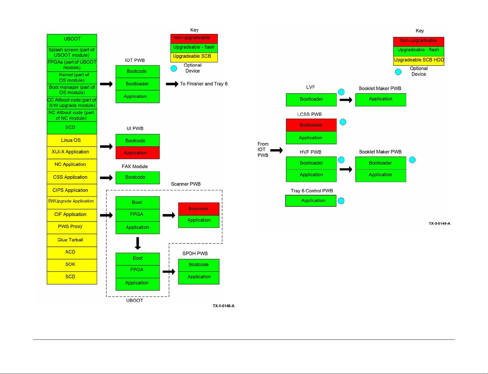
Figure 3 Software upgrade information (1 of 2)
Figure 4 Software upgrade information (2 of 2)
Launch Issue
Xerox® AltaLink® B8090 Family Multifunction Printe r
April 2017
8-17
Principles of Operation
Page 18
Single Pass Document Handler (SPDH)
Overview
The Single Pass Document Hand ler (SPDH) is mounted above the pl aten scanner. Together
the SPDH and platen scanner form the image input terminal (IIT) for the AltaLink® B8090F
machines. (See also Scanner Overview.)
The SPDH allows a user to scan origi nal documents of various sizes and original types to
enable either the system c opy or system scan to file functional ity. The user inter acts with the
SPDH in the following ways:
• Lifting and lowering the SPDH to access the document glass for registering original documents for platen scanning
• Lifting and lowerin g th e SP DH to a cc ess the do cu men t glas s an d CV T g lass s urfac es f or
cleaning and maintenance
• Loading original documents into the input tray of the SPDH
• Adjusting the document width guide positions to register the original document
• Removing re-compile d original docume nts from the SPDH output t ray once scanning is
complete
• Lifting and lowering the SPDH to ope n the SPDH paper path for the remov al of jammed
sheets, and to allow access to the side 2 scan assembly for cleaning
The SPDH is a center registered automa tic doc ument han dler, that se parates and feeds up to
200 (face up) original documents of 80gsm individually in 1 to N order. It is capable of scanning
simplex (this mode scan s only on e sid e of a doc ument set) and d uplex ( this mode scan s both
sides of a document set) documents . For simplex images the SPDH transports documen ts
over the CVT window of the pla ten scann er. The do cumen t is the n transpo rted to the r e-stac k
tray. For duplex images side 2 of the document is scanned via the side 2 scan assembly as the
document is transported to the re-s tack tr ay. The sid e 2 scan assemb ly is mo unted in ternal to
the SPDH. Document output to the re-stack tray will be in the same order as input (face down),
Figure 1.
Input tray
Principles of Operation
April 2017
8-18
Restack tray
Figure 1 SPDH
Launch Issue
Xerox® AltaLink® B8090 Family Multifunction Printer
Page 19
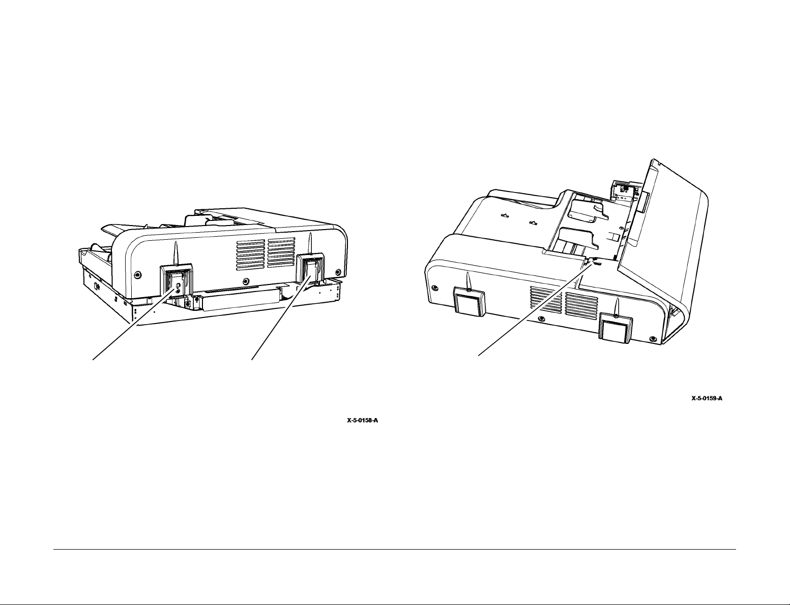
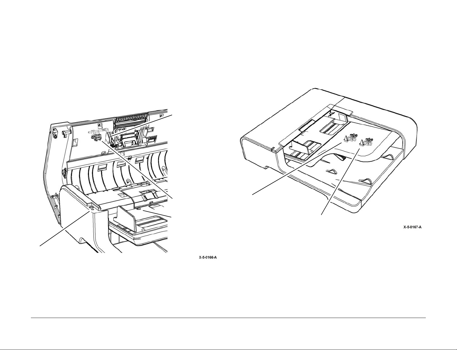
Counterbalances
Two counterbalance assemblies, Figure 2, secure the document handler to the scanner frame.
A counterbalancing force is generated by compression springs acting on a cam-follower
arrangement, all housed within sheet metal brackets. Above a set drop-down angle, the SPDH
will hold or rise slowly to the maximum opening angle. Bel ow the set drop-down angle, the
SPDH will gently close onto the sca nner. The right hand brac ket provides a me ans of adjust
ment for document skew. In addition, the counterb alance assemblies are double-hinged to
allow a customer to close the SPDH onto books of up to 25mm in thick ness without appl ying
excessive force to the doc ument glass of the scanne r. This feature is known as bo ok-mode
operation.
SPDH Power
The SPDH top cover interlock s witch, S05-305, Figure 3, is located at the rear of the SPDH.
S05-305 controls the +24V supply to all clutches, solenoids, motors and the side 2 scan
assembly via the SPDH PWB . The SPDH top cover switch isolates the SPDH +24V circuit
when the top cover asse mbly is opened. The inte rlock is used to ensure o perator safety by
-
removing power to the SPDH driv es when not actuated. The scanner PWB su pplies +3.3V,
+5V, +12V and +24V to the SPDH PWBA. The SPDH PWB then controls the output of powe r
to all the components in the SPDH.
Right counterbalance Left counterbalance
Figure 2 Counterbalances
Launch Issue
Xerox® AltaLink® B8090 Family Multifunction Printe r
April 2017
8-19
Top cover interlock switch
Figure 3 Top cover interlock switch
Principles of Operation
Page 20
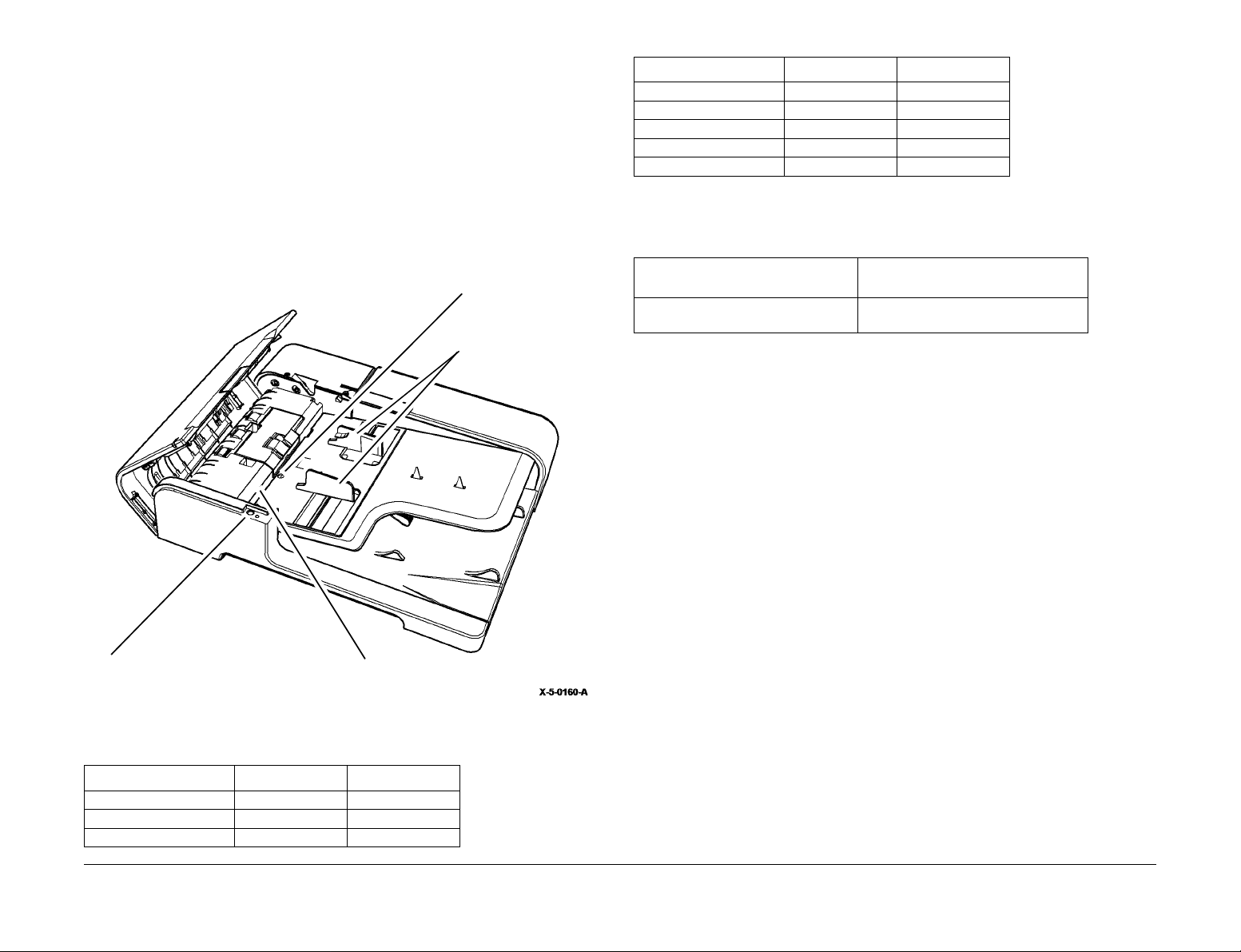
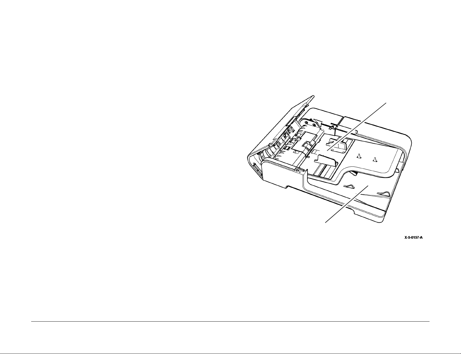
Input Tray
s
Copies are placed into the input tray face up, 1 to N order. The capacity of the input tray is 200
originals of 80gs m w eight. The mi nimum siz e origi nal i s A5 ( 5.5 X 8.5 in ch), SEF o r LE F. The
maximum size of original is A3 (11 X 17 inch), SEF only . Table 1 lists re cognized pape r sizes
and orientations. Intermi xed lengths (feed direction) are accepta ble for a limited number of
document pairs, which ar e des cribed b elow in the Mixed S ize M ode secti on. T he tray wi ll pro
vide for center feedi ng in 1 to N sequ ence. Movable tray gu ides for the docume nt width are
provided. Correct guide adjustmen t by the operator is imperati ve for reliabl e feeding and auto
paper select. The SPDH document present sensor (Q05-309), detects originals loaded against
the document registration wall. When the SPDH document present sensor is actuated the doc
ument set LED (LP05-084), illuminates. Refer to Figure 4.
Refer to Table 1 and Table 2 for details of document sizes.
Document present
sensor
Document width guide
T able 1 Document sizes
Document Sizes SEF Document LEF Document
8.5 x 11 Yes Yes
8.5 x 13 or 8.5 x 14 (1) Yes No
-
B4 Yes No
A3 Yes No
11 x 7 Yes No
-
NOTE: (1) The SPDH cannot differen tiate between these sizes. The UI wil l display relevant
media size dependent upon market region stored in NVM.
Table 2 Document sizes
Maximum and Minimum document size
in the process direction
138mm/5.4 inches to 432mm/17
inches
Document Size Sensing and Selection
Document size sensing and selection is achieved by a combination of:
• Width sensing (cros s-process direction).
• Static and dynamic length detection (process direction).
• Mixed Size Mode.
Static Size Sensing
Maximum and Minimum document size
in the cross process direction
138mm/5.4 inches to 432mm/17 inch es
Document set LED
Figure 4 Input tray
Table 1 Document sizes
Document Sizes SEF Document LEF Document
A5 or 5.5 x 8.5 (1) Yes Yes
B5 Yes Yes
A4 Yes Yes
Principles of Operation
Document registration wall
The SPDH determines the s ize of th e of th e or i gin al d ocument and whether the paper is being
fed long-edge feed (LEF) or shor t-edge feed (SEF) upon the combin ed sign als from the docu
ment side guide width sensors and the input tray length sensors. Each combination of the input
tray sensing regions have an associated default paper size, so when a user places a document
into the input tray the SPDH makes an assumption of the loaded document size.
Static Width Sensing
Three document width s ensors determine the width of the ori ginal document, wi dth sensor 1
(Q05-325), width sensor 2 (Q05-326), and width sensor 3 (Q05-327). The width sensors detect
flags mounted to the bottom of the movable in-board and out-board document side guides. The
document side guides are cen trally register ed and synchrono usly move via a rack and pinion
mechanism. As the guides mov e, the flags block and unblock the wi dth sensors. The SPDH
uses the signals from the width sens ors to determine pape r width of the original docum ent. If
the guides are not positioned correctly then the top edge registration and LE skew of the
scanned documents cannot be guaranteed. The guides provide some resistance to movement
so that they remain in position du ring the scanning of the original do cument. The side guide s
also limit the maximum thickn es s of orig ina l doc um ent st ack tha t can be load ed wit h stack lim
iting features.
April 2017
8-20
Xerox® AltaLink® B8090 Family Multifunction Printer
Launch Issue
-
-
Page 21

Static Length Sensing
Auto Reduction/Enlargement
Static length detection is used to determine document length of the original document, for most
document sizes and orientations. This is accomplished with two sensors, length sensor 1,
Q05-315, and length sensor 2, Q05-320, located in the input tray, which are at appropriate dis
tances from the docume nt r eg istr ation wall. The state of these two le ngth s ensor s whe n d ocu ments are loaded from against the document registration wall at start of a job will determine the
stack length range.
Dynamic Length Sensing
Dynamic length sensing is utilized to determine the length of docu ments that are not recognized by the static le ngth sensors. This featur e only works if the paper su pply automatically
select feature has been chosen by the operator.
At the start of a c opy job the i mage data of the first s canned docume nt of unknown length is
reconciled with docu ment length data stored on SB C PWB. If the scanned image leng th is
matched with stored document length data on the SBC PWB, image processing will continue. If
no document length match is foun d the SB C PWB wil l reques t a UI stat us mess age to be d is
played to the operator to enter the required paper size.
Dynamic length sensing is required for the document sizes shown in Table 3.
Table 3 Document sizes
Document size
8.5” x 11” SEF
A5 LEF
8.5” x 5.5” LEF
A5 SEF
8.5” x 5.5” SEF
In combination with mixed s ize mode the user can select auto reduction/enlargemen t. When
selected the document will be scanned to the copy paper size. All copy enlargement and
-
reduction is controlled by the SBC PWB.
-
Mixed Size Mode
This option is selected thr oug h th e fea tures i n the us er in ter fac e a nd a llows the us er to c op y a
set of documents th at contai n two di fferen t si ze s as l isted i n Ta ble 4. With all Mixed size origi
nal jobs, both sizes in the pair must be of the same cross-process width.
Table 4 lists the valid pairs of doc ument sizes which the I IT will recognise and enable as a
mixed size mode job. Dur ing mixed size mode dynami c length sensing will be p erformed on
each individual scanned document.
T able 4 Document sizes
Valid document pair Short doc length
A3 SEF + A4 LEF 210mm
A4 SEF +A5 LEF 148mm
8.5” x 11 SEF + 8.5 x 5.5 LEF 139.7mm
8.5 x 14 SEF + 8.5 x 11 SEF 279.4mm
11 x 17 SEF + 8.5 x 11 LEF 216mm
B4 SEF + B5 LEF 176mm
Launch Issue
Xerox® AltaLink® B8090 Family Multifunction Printe r
April 2017
-
Principles of Operation
8-21
Page 22
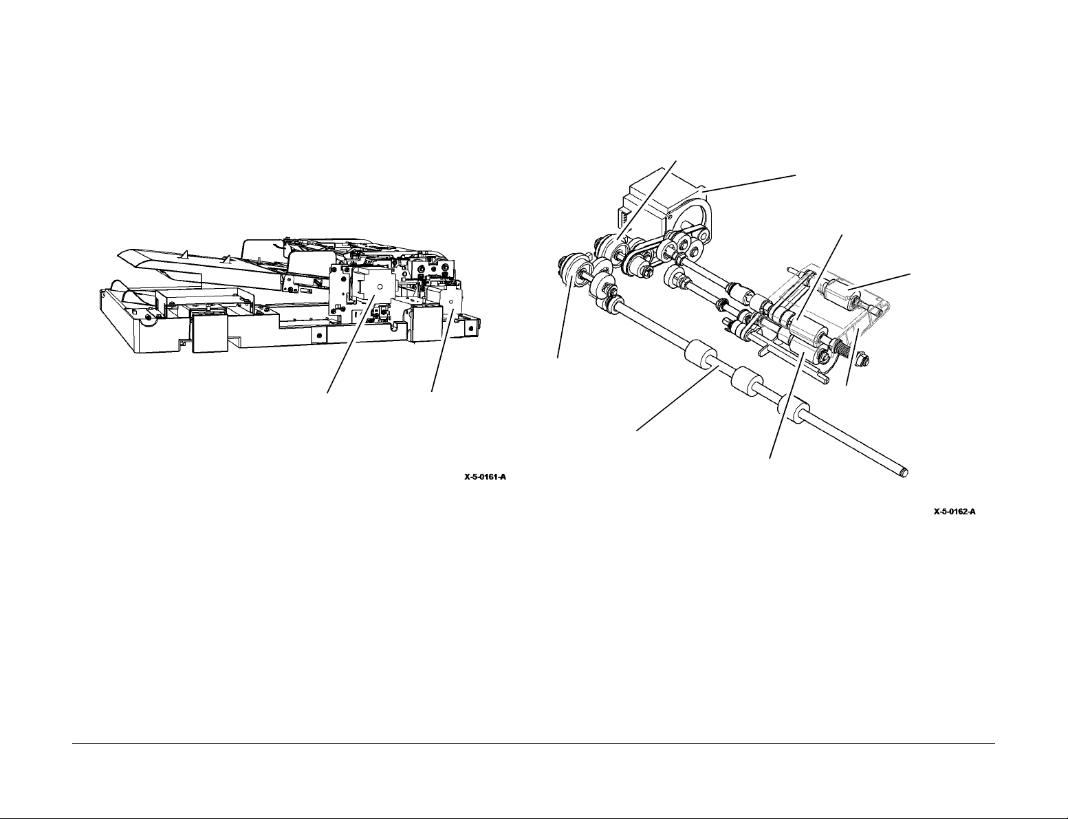
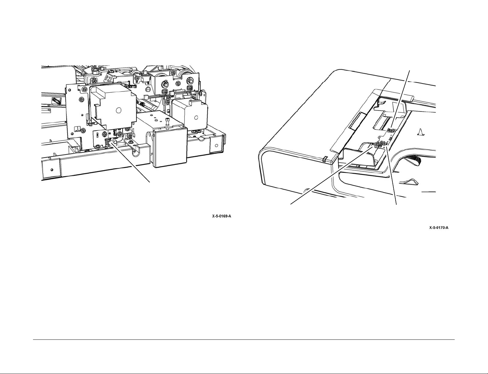
Drives
Three 24V motors provide the drive for the SPDH components, the feed motor and read
motors are shown on Figure 5, the Tray elevator motor is shown on Figure 8.
Feed Motor
The feed motor (PL 5.18 Item 2) supplies continuous drive via a toothed belt and gears to both
the takeaway roll clutch, CL05-425, and feed clu tch, CL05 -0 25, du ring the scan pr oces s of the
document. The TAR clutch, when energized provides drive to the takeaway roll. The feed
clutch when energized provides drive to th e feed, nudger and retard r olls that form the full y
active retard feed assembly, via their respective gear trains, Figure 6.
Feed clutch
Feed motor
Feed roll
Nudger roll
TAR clutch
Principles of Operation
Feed motor Read motor
Figure 5 Feed motor and read motor
Fully active retard (FAR) feed
mechanism
Takeaway roll assembly
Retard roll
Figure 6 Feed motor
April 2017
8-22
Xerox® AltaLink® B8090 Family Multifunction Printer
Launch Issue
Page 23
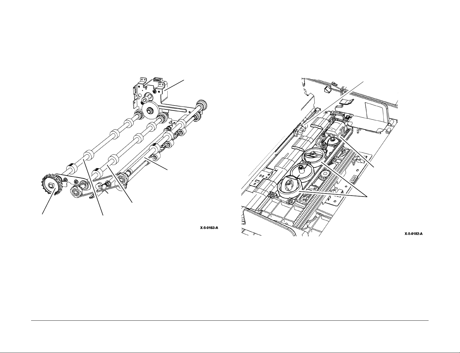
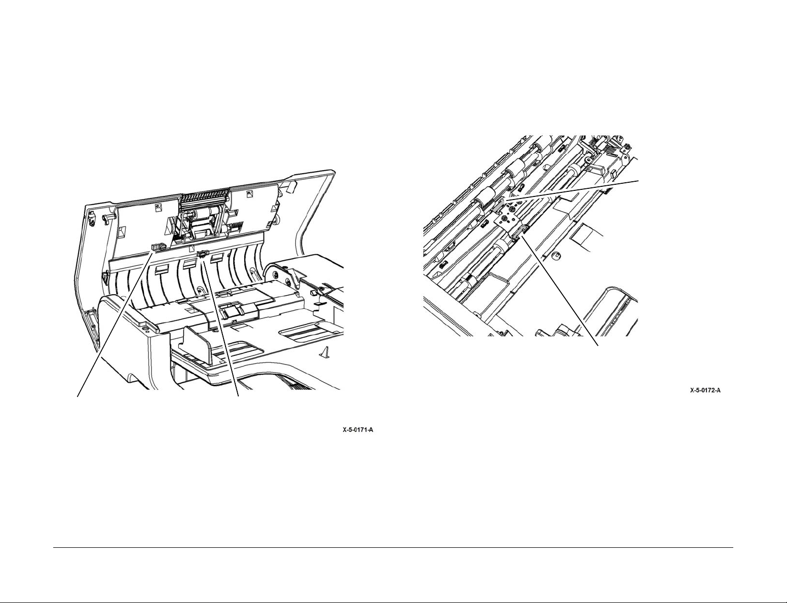
Read Motor
The read motor (PL 5.1 8 Item 1) supplie s continuous dr ive to the pre scan r oll assembly and
mid scan roll assembl y. The exi t roll assem bly is dr iven by a p ulley and to othed b elt arrang e
ment from the mid scan roll, Figure 7. The rea d motor also provides the drive (when run in
reverse) for the side 2 scan assembly calibration mechanism, shown in detail in Figure 16. The
exit jam clearance knob (PL 5.17 Item 5), under the front left corner of the SPDH, can be used
to clear jams and feed documents along the document path to activate sensors for diagnostics.
Tray Elevator Motor
The tray elevator motor (PL 5.30 Ite m 1 4) raises and lowe rs the input tr ay in order to mai ntain
-
the document stack at the optimum feed position, Figure 8. The motor drives a gear chain that
rotates a pair of actuators that raise and lower the tray.
Lift Home Position Sensor
The lift home position (lowered) sensor, Q05-307 , is a flag actuated sensor th at senses the
input tray is in the home position, Figure 8.
Exit jam clearance knob
Mid scan roll assembly
Pre scan roll assembly
Figure 7 Read motor
Read motor
Exit roll assembly
Lift home position sensor
Tray elevator motor
Actuators
Figure 8 Tray elevator motor
Launch Issue
Xerox® AltaLink® B8090 Family Multifunction Printe r
April 2017
8-23
Principles of Operation
Page 24

Scanning Process
1. The document present s ensor, Q05- 309, detect s that a docum ent has be en loaded o nto
the input tray and positioned against the registration wall of the separation assembly.
2. At the detection of a d oc ume nt, o r at p ower o n, t he S P DH i nit ial izes th e c alib ra tio n of the
side 2 scan module and platen scanner.
3. The size of the document is calcula ted by a combinati on of signals from width se nsor 1,
Q05-325, width sensor 2, Q 05-326, width se nsor 3, Q05-327, a nd length sensor 1 Q 05315, and length sensor 2, Q05-320.
4. The input tray elevator mechani sm, in con junct ion with the stack height sensor Q05 -310,
raises the input tray to position the doc ument stack at the optimum heigh t for feeding at
the start of a copy job . The tr a y he ig ht will r ais e in i nc re men ts (a ppr oxim ate ly at e ve ry 25
sheet feed for xerox 8 0gs m pa per) to ma in tai n a n o pti mum fe edi ng po sitio n throughout a
copy job.
5. By means of a fully active reta rd feed mechanism the SPDH feeds the document s from
the input tray into the paper path of the SPDH. The feed and read motor are activated and
the feed clutch is energized. On activation of the feed clutch the nudger roll is driven down
onto the document stack. Simultan eou sl y as the feede r me chani sm drive s the nud ger ro ll
down it raises the two gate finge rs. The nudger drives the top document off the s tack
across to the separation assembl y and in to the full y active re tard nip, fo rmed by the feed
and retard rolls (see Docum ent Separation) . The nudger roll rema ins energized until the
lead edge of the docu me nt arr ives at the feed se nsor , Q 05 -330. W he n th e l as t docum ent
has been fed the feed m otor mom enta rily ru ns in r evers e, this ena ble th e feede r me cha
nism to raise the nudger roll and drop the two gate fingers.
6. The feed sensor, Q05-330, positioned between the TAR nip and the separation nip
detects the lead edge (LE) of a doc ument once it has been acquired and th en the trail
edge (TE) to confirm an inter document gap (IDG).
7. The document momentarily butts against the takeaway roll assembly where the document
realigns if skewed. The document has space to corrugate witho ut creasing within the
buckle chamber of the document handler.
8. The feed clutch, CL05-025, is deenergized, thereby de-coupling the nudger and feed rolls
and the takeaway clutch, CL 05-425, is energized and the take away roll assembly pulls
the document through the FAR nip.
9. The document contin ues through the takea way nip until the lead edge is dete cted at the
registration sensor, Q 05-340, and the ta keaway clutch , CL05-425, is de energized. If the
SPDH has not received a feed request signal from the scanner PWB the takeaway clutch,
CL05-425, will de-energise and the document feed will stop. If the feed request signal has
been received the document will continue to be scanned.
10. The feed request signal starts the scanning operation. The read motor drives the pre scan
roll assembly, which transpor ts the document across the image ar ray for scanning, and
onto the mid scan roll assemb ly. Since the rolls driving the pap er are controlled by the
same timing belt and motor, the velocity of the paper is constant.
11. If a simplex job has been requested the document passes the CVT window, is lifted by the
CVT ramp, and is deliv ered into the re- stack tray. If a dupl ex job has been r equested a
scan of side two of the document is made. The side 2 registration sensor, Q05-343,
detects the lead edge of the doc ume nt in ord er to tim e the s tart of the side two scan. The
document then continues into the re-stack tray after side two is scanned.
Document Separation
The separation of documents is performed by the feeder assembly working in conjunction with
the separation ass emb ly and operates on a diff er enti al of fric ti on princ i ple . T he fe ed as sembl y
contains the nudger a nd feed rolls and the separation assem bly contains the retard roll. The
retard roll is dri ven via a s lip cl utch, and in the op erati onal positi on it is spr ung l oaded again st
the feed roll to form the separation nip.
The feed roll has a high coefficie nt of friction with the do cuments fed from the in put tray. The
retard roll also has a coeffic ient of friction with th e documents fed fro m the input tray but one
that is lower than that of the feed roll, though higher than the coefficient of friction between two
documents.
Once activated the nudger roll feeds the top document off the input tray and into the separation
nip. In turn the feed roll drives the top document towards th e TAR assembly while the r etard
roll is driven in the op posite direc tion, in order to seg regate all documents other than the top
document passing through the FAR nip.
The feed roll transports the top document in the proc ess dir ec tion bec au se it has a high coe fficient of friction with the top document. The top document is given a coefficient of friction due to
the force imparted by the feed roll and ov ercome s the torque suppli ed by the sl ip clutch of the
retard roll. This causes the retard roll to be driven by the feed roll. If more than one document is
fed from the document stack on the input tray, documents other than the top document are put
in contact with the retard roll. The se lowe r docu men ts are pr evente d fr om be ing tra nspor ted in
the process direction because the torque of the ret ard roll slip c lutch is not ov ercome by the
friction between the two docu ments, resulting in only the top sheet being tr ansported in the
process direction toward the TAR assembly.
Principles of Operation
April 2017
8-24
Launch Issue
Xerox® AltaLink® B8090 Family Multifunction Printer
Page 25
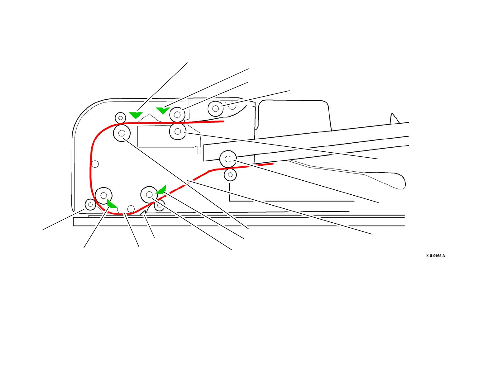
5.4 SPDH Sensors
There are several sen sors located throughout the document path to detec t the positi on of the
document. The signals from these sensors initiate operations within the SPDH, and also assist
with jam detection, Figure 9.
Takeaway sensor
Feed sensor
Feed roll
Nudger roll
Retard roll
Pre scan roll
Registration sensor Side 1 scan line Mid scan roll
Launch Issue
Xerox® AltaLink® B8090 Family Multifunction Printe r
CVT ramp
TAR roll
Side 2 registration sensor
Figure 9 SPDH document path
April 2017
8-25
Exit roll
Side 2 scan line
Principles of Operation
Page 26
Sensor Types and Locations
Document Present Sensor
The document present sensor, Q05 -309 (PL 5.30 Item 6), is a r eflection a ctuated sen sor that
senses the presence of a document loaded into the input tray, Figure 10. When the SPDH doc
ument present sensor is actuated the docum ent set LED, LP05- 084, illuminates in the SPDH
top cover. When the last she et has left the inp ut tray the sensor triggers t he signal to stop the
document feeding process.
Stack Height Sensor
The stack height sensor, Q05-310 ( PL 5.20 Item 4) , is a flag ac tuated sensor that senses the
paper stack and maintains the stack height by triggering activity of the tray elevator motor, Fig
ure 10.
Stack height sensor
actuator
Length Sensor 1
The length sensor 1, Q05-3 15 (PL 5.30 Item 5), is a fl ag actuated sen sor that sense s documents in the input tray longer than 300mm, Figure 11.
-
Length Sensor 2
Length sensor 2, Q05-320 (PL 5.30 Item 5), is a flag actuated sensor that senses documents in
the input tray longer than 240mm, Figure 11.
-
Document set LED
Principles of Operation
Figure 10 Paper stack sensors
Stack height sensor
Document present
sensor
April 2017
8-26
Length sensor 2
Length sensor 1
Figure 11 Length sensors
Launch Issue
Xerox® AltaLink® B8090 Family Multifunction Printer
Page 27
Calibration Home Position Sensor
The calibration home posit ion sensor , Q 05-36 0 ( PL 5.18 Item 9), is a flag actuated sensor that
senses that the calibration strip of the side 2 scan assembly is in the home position, Figure 12.
Calibration home position sensor
Width Sensors: 1, 2 and 3
Width sens or s (PL 5.30 Item 5) 1, Q05-325, 2, Q05-326, and 3, Q05-327, are actuated by flags
attached to the document wid th gu ide s o f the i npu t tray . The 3 wi dth se nsor s are p os itione d to
allow the detection of common document widths. Working with length sens ors 1 and 2 they
enable the machine software to determine various document sizes, Figur e 13.
Width sensor 1
Figure 12 Calibration home position sensor
Launch Issue
Xerox® AltaLink® B8090 Family Multifunction Printe r
April 2017
8-27
Width sensor 3 Width sensor 2
Figure 13 Width sensors
Principles of Operation
Page 28
Feed Sensor
The feed sensor, Q 05-330 (PL 5.20 Item 9), is a reflection activated sensor that senses the
lead edge and trail edge of documents leaving the feed assembly to confirm the presence of an
inter document gap, Figure 14.
TAR Sensor
The takeaway sensor, Q0 5-335 (PL 5.20 Item 9), is a reflection acti vated sensor that senses
the lead edge and tr ail edge of documen ts entering the takeaway roll ass embly. This sens or
triggers the stop of the separation nip and nudger rotation. This allows the takeaway roll
assembly to pull the doc ument through the separation nip to ensure an interdocum ent gap,
Figure 14.
Registration Sensor
Registration sens or, Q05-340 (PL 5.18 Item 9), is a reflection activated sensor that senses the
lead edge and trail edge of documents just prior to the side 1 scan area, Figure 15.
Side 2 Registration Sensor
The side 2 registration se nsor, Q05-34 3 (PL 5.18 It em 9), is a reflection activated sensor that
senses the lead edge and trail edge of documents just prior to the side 2 scan area, Figure 15.
Registration sensor
(side 1)
Feed sensor Takeaway sensor
Figure 14 Feed and takeaway sensors
Principles of Operation
April 2017
8-28
Side 2 registration sensor
Figure 15 Registration sensors
Launch Issue
Xerox® AltaLink® B8090 Family Multifunction Printer
Page 29

Side 2 Scan Assembly C al i b ra ti o n
The calibration mechanism consists of a white calibration strip attached to the glass surface of
the scanner face on th e underside o f the scanner. The white strip on the glas s surface oper
ates as a spring loaded sliding shutter driven by a pair of cams. The white calibration strip provides a scannable area for th e ful l w idt h of t he s ide 2 s c an a ssem bly , a nd s erv es as a uni for m
reference for the video control system that uses it to calibrate the video data.
Calibration is nece ssary because tolerance variatio ns in the scanner may result in different
video data. The calibration procedure scans the calibrati on strip, compares the sign als to set
point values stor ed as Non-Volatile Memor y (NVM) data, and then cal culates a white point
value to ensure consistent video data. There is no black calibration strip. Black calibration is
performed with the lamp off.
Calibration of the side 2 scan assembly is performed at power on or the sensing of a document
in the input tray. At the time of calibr ation the read moto r is driven in the op posite rotational
direction to that of the scanning proc ess. The spring loaded sliding glas s of the side 2 scan
assembly is moved by a cam and actuator arran gement. A pair of ca ms is rotated on a cam
shaft via a belt and pulley syst em. In norm al oper ation th e mechanis m is prev ented from rotation by the use of a one way clutch-gear.
As the cams rotate they push against followers at either end of a pivot shaft that move a pair of
actuators. The inboard a nd outboard actuators push against pegs attached to the s canner
glass. The action of the actuators on the pegs cause the glass to slide in the scan process
direction, positioning the calibration strip directly under the scan line of the side 2 scan assem
bly. Once the calibration strip is in this position the calibration process takes place.
Further reverse rotation of the cam disengages the two actuators and the spring loaded shutter
returns to it’s scannin g operation p osition. A flag on th e inboard end of the cam shaft s ignals
the calibration hom e position sensor, Q05-360, that th e calibration strip of the side 2 scan
assembly is in the home position, Figure 16.
-
-
-
Launch Issue
Xerox® AltaLink® B8090 Family Multifunction Printe r
April 2017
8-29
Principles of Operation
Page 30

Side 2 Scan Assembly C al i b ra ti o n Drive Train
The drive train for the side 2 sca n assembly cal ibration mec hanism is as follows (refer to Fig-
ure 16):
1. Read motor, PL 5.18 Item 1(not shown).
2. Read motor idler gear, PL 5.19 Item 16.
3. Mid scan drive gear, PL 5.19 Item 12.
4. Mid scan roll, PL 5.17 Item 3.
5. Mid scan roll pulley PL 5.19 Item 18.
6. Exit roll drive belt, PL 5.19 Item 19.
7. Exit roll pulley, PL 5.19 Item 21.
8. Exit roll assembly, PL 5.17 Item 2.
9. Calibration shutter drive gear, PL 5.19 Item 8.
10. Calibration shutter idler gear, PL 5.19 Item 6.
11. Calibration shutter driven gear, PL 5.19 Item 7.
12. One way gear clutch.
13. Cam shaft
14. Front calibration cam, PL 5.19 Item 20.
15. Cam follower
16. Pivot shaft.
17. Outboard (front) actuator and inboard (rear) actuator.
Principles of Operation
April 2017
8-30
Launch Issue
Xerox® AltaLink® B8090 Family Multifunction Printer
Page 31

5.
Mid scan roll pulley
6.
Exit roll drive belt
7.
Exit roll pulley
8.
Exit roll assembly
14.
Front calibration cam
15.
Cam follower
13.
Cam shaft
2.
Read motor idler gear
9.
Calibration shutter drive gear
12.
One way gear clutch
17.
Outboard actuator
(front)
Actuator acting on peg
Pre scan roll
Calibration strip on the scanner glass 17.
Launch Issue
Xerox® AltaLink® B8090 Family Multifunction Printe r
4.
Mid scan roll
3.
Mid scan drive gear
Pre scan roll drive gear
Figure 16 SPDH scanner calibration
April 2017
8-31
16.
Pivot shaft
10.
Calibration shutter idler gear
11.
Calibration shutter driven gear
Calibration home position sensor
Calibration home position sensor flag
Inboard actuator (rear)
Principles of Operation
Page 32

DC Routines and Adjustments
• dC604 Registration Setu p Procedure. This routi ne measures and adjustmen ts image to
paper registration for the Image Output Terminal. It must be performed whenever a part is
changed, removed or replaced within the SPDH and scanner module.
• dC608 Document Feeder Reg istration. This routine check s the registration of the document feeder and corrects any misalignment. The process runs automatically and does not
require any user inter vention other than inserting three bla nk sheets in the document
feeder. This routine must be performed whenever a part is changed, removed or
replaced, including a complete SPDH module.
• dC609 Document Glass Registration. This feature checks the r egistration of the document glass and corrects an y misalignm ent . The process runs autom aticall y and doe s not
require any user interventi on other tha n keepin g the SP DH open d uring the o peration . It
routine must be p erformed when ever a part is changed, removed or r eplaced withi n the
scanner module.
• dC610 CCD Lamp Profi le Adjus tment. Th is routin e adjusts the side 1 (scanner ) then the
side 2 (SPDH) scan lamps to maintain optimum image quality.
• dC945 IIT Calibratio n. This rout ine auto matically calculates and sets the white-re ference
correction factor for paper whit e and calibra tion strip v ariations. Thi s procedure must be
run whenever a side 2 scan assembly, scan carriage assembly, scanner module, scanner
module component, or a complete SPDH is removed
• ADJ 5.1 SPDH Drive Belts Adjustment
• ADJ 5.1 SPDH Height Adjustment
• ADJ 5.2 SPDH Skew Adjustment
• ADJ 5.3 SPDH Cleaning Procedure
Principles of Operation
April 2017
8-32
Launch Issue
Xerox® AltaLink® B8090 Family Multifunction Printer
Page 33

Fusing and Copy Transportation
Fusing
The primary function of th e fuser module is to fix the t oner to the media a nd to transport that
media from the pr e fuser transport to the p ost fuser transport with no damage or excessi ve
curl. Fixing the tone r to the me dia is done by a combina tion of heat and pressur e. There a re
four fuser module configurations 45-55ppm (50Hz and 60Hz) and 65-90ppm (50Hz and 60Hz).
Heat warning lab els and fl ocking a re used t o prev ent the cus tomer f rom contac ting high temperature surfaces.
The fuser module receives its drive from the drive assembl y. After the toner image is trans ferred to the paper, the paper passes throug h the fus er . The pr essu re roller is press ed again st
the heat roller to melt the toner and bond the image to the paper.
The fuser module is a customer replaceable unit (CRU) (PL 10.8). The average life of the fuser
module is 350,000 prints. A CRU m onitor (CRUM) in the fuser module ensures the correct
module is installed for the mar ket regi on of the mac hine and mo nitors th e remainin g life of the
fuser. When a new fuser module is installed, the fuser life counters are reset.
There are four types of fuser (PL 10.8 Item 1):
• 50Hz for AltaLink® B8045/B8055
• 50Hz for AltaLink® B8065/B8075/B8090
• 60Hz for AltaLink® B8045/B8055
• 60Hz for AltaLink® B8065/B8075/B8090
If a 50Hz fuser is install ed in a US market re gion machine or if a 60Hz fuser is install ed in a
European market region machine a 310-399-00 Fuser CRUM incompatibility fault will be
declared.
The following information pertaining to fuser module life is available to the customer via the UI:
• Projected end of life (estimated days remaining).
• Image count (estimated pages remaining).
• Life remaining (estimated percent remaining).
• Re-order notification.
• Configuration of re-order information (set by System Administrator - 0 to 20 days).
Fuser Components
Fuser Roll
The fuser roll is heated by two internal halogen lamps, and contacts the pressure roll to form a
nip through which t he media is tra nsported. Th e toner i s melte d by the fus er roll and pre ssed
into the media by the pressure roll. Drive for the fuser module is provided by the main drive via
a gear on the fuser roll.
Pressure Roll
The pressure roll is a metal shaft coated with a hard silicone rubber and a PFA sleeve. It maintains pressure on the paper pas sing between it and the heat r oller. This pressure bonds the
melted toner to the paper.
Springs are used to force the fu ser roll and p ressure roll together. The pressure rol l is pulled
upwards into the fuser roll by springs maintaining nip force. The pressure roll is at a 10 degree
angle to the fuser roll. The pressure rol l has a slight symmetrical profil e with nominal outside
diameter of 30mm.
Heat Lamps
Two halogen lamps are used to heat the fuser roll and are mounted in parallel along the bore of
the fuser roll. Refer to Table 1 for the heat lamp power.
Table 1 Heat lamp power
Machine
speed
45-55ppm 50Hz 825W @230V AC 655W @230V AC
65-90ppm 50Hz 825W @230V AC 910W @230V AC
45-55ppm 60Hz 825W @115V AC 655W @115V AC
65-90ppm 60Hz 825W @115V AC 910W @115V AC
Temperature Sensors
The temperature sensors are contac t thermist ors having a kno wn value of resis tance that varies with temperature. Ther e are two temperature sensors in the fuser. One is located at the
center of the heat roller, the other is located toward the front of the heat roller. Both thermistors
monitor the temperature of the heat roller. Refer to Figure 1.
Frequency End lamp
A4 (8.5 x 11 inches)
SEF
The fuser roll is a s teel tube with a PFA coating . It has a symmetr ic profiled sh ape to ensu re
the edges of the paper move slightly faster than the center for wrinkle control.
• AltaLink® B8045/B8 055 - the fuser roll is 0. 75mm thick and has a nom inal 30 mm diam eter.
• AltaLink® B8065/B8 075/B8090 - the fus er roll is 0.75mm thi ck and has a nomin al 30mm
diameter.
Launch Issue
Xerox® AltaLink® B8090 Family Multifunction Printe r
April 2017
Figure 1 Lamps and temperature sensors layout
Principles of Operation
8-33
Page 34

Thermostats - Thermal Cutouts (TCO)
Two non resettable thermostats (TCOs) are mounted directly above the center of the fuser roll.
They provide the final level of safety for the fuser system.
• In a case where the temperatu re control system fails to operate c orrectly the TCO will
blow when the temperature at the thermistor is 227 degrees C.
• There is a temperature differ entiation between the th ermisto r and the fu ser due to the air
gap between the two.
• When the thermistor detects 227 degrees C the temperature at the fuser roll will be
approximately 272 degrees C.
When the TCO blows p ower to the lamps i s cut preventing damage to the modu le. If a TCO
blows a new fuser module must be installed. Refer to Figure 2.
TCO 1 and TCO 2
Stripper Fingers
Five stripper fingers are kept in light contact with the fuser roll by spring tension. These prevent
paper from remaining attached to the fuser roll. Refer to Figure 3.
Drawer connector
Stripper finger (5)
Pressure roll
Heat roll
Heat lamps (2)
Figure 3 Fuser components
Principles of Operation
Figure 2 TCOs and thermistors
Thermistor 1 and
thermistor 2
April 2017
8-34
Launch Issue
Xerox® AltaLink® B8090 Family Multifunction Printer
Page 35

CRUM
The CRU monitor (CRUM) is used to identify the type and age of the fuser module. It also identifies the market reg ion and stores th e print count. It also acts a s an interloc k. If the machi ne
senses that the CRUM is disconnected, the machine will not run. Refer to Figure 4.
CRUM
Drawer connector
Drawer Connector
The drawer connector (Fi gure 4) provide s the interfac e to the power and cont rol for the fuser.
Refer to Figure 5 for pin number locations on the fuser side, PJ100:
• Pin 1 thermistor 1 and thermistor 2 RET.
• Pin 2: thermistor 1.
• Pin 3: thermistor 2.
• Pin 7: lamp 2 RET (A4 SEF).
• Pin 8: AC Supply.
• Pin 9: lamp 1 RET (A4 LEF).
• Pin 10: AC GND.
Pin 10
AC GND
Pin 7
Lamp 2 RET
Pin 3
Thermistor 2
Figure 4 CRUM and drawer connector
Launch Issue
Xerox® AltaLink® B8090 Family Multifunction Printe r
April 2017
8-35
Pin 9
Lamp 1 RET
Pin 1
Pin 8
Thermistor 1 and 2 RET
AC Supply
Figure 5 Fuser drawer connector pins
Pin 2
Thermistor 1
Principles of Operation
Page 36

Fuser Paper Guides
Refer to Figure 6. The fuser has the following paper guides:
• Left input guide. This guides the paper into the fuser.
• Right input guide. The r ight input guide is floc ked and has the dual fun ction of assisting
with the alignment of t he media on fus er entry and prev enting an operator from gaining
access to the hot fuser ro ll. In addition, it help s guide the paper i nto the fuser, ensuring
that the lead edge contacts the fuser roll first.
• Left output guide. This guide hinges open to aid jam clearance.
• Right output guide. Th is guides the pape r to the post fuser tra nsport roller. The st ripper
fingers are mounted to this guide.
Left input guide
Right input
guide
Fuser entrance
Right output
guide
Fuser exit
Left output guide
Fuser Life Expectancy
Life expectancy of the fuser is dependent on the speed of the machine:
• 45ppm - 264,000 prints
• 55ppm - 300,000 prints
• 65ppm - 315,000 prints
• 76ppm - 330,000 prints
• 90ppm - 345,000 prints
Several other factors can reduce fuser life:
• Greater than 5% coverage.
• Paper use larger than letter size.
• Printing on heavy media.
• Printing short-edge feed.
• Printing on transparencies or speciality media.
Fuser Operating States
Refer to Table 2. The fuser has the following operating states:
• Warm up state.
• Stand-by state.
• Run state.
• Power save (off) state.
• Power save (simmer) state.
Table 2 Fuser temperatures
NVM Description
FsrStandbyTemp
FsrRange Temperature range below
FsrRunTemp Target temperature during
HeavyWeightMediaTempOffset
Target temperature during
standby mode.
FsrStandbyTemp at which
start print can begin.
run mode.
Temperature offset added to
fuser temperature media over
120gsm.
Machine speed (PPM)
45 55 65 75 90
60 C. 60 C. 60 C. 60 C. 60 C.
20 C 20 C 20 C 20 C 20 C
195 C. 195 C. 200 C. 200 C. 200 C.
+10 C +10 C +10 C +10 C + 10 C
Principles of Operation
Figure 6 Fuser guides
Warm up State
The fuser enters the warm up state when ‘thermistor measured temperature is less than (NVM
value FsrStandbyTemp minus NV M value F srRunTe mp) wh en IOT i s powere d from pow er off
state’.
When the fuser is in the warm up state, the IOT informs the device controller that the fuser is in
the warm up state. The user is info rmed via the UI tha t the fuser is warming up and pri nting is
inhibited until the me asured temperature is within (NVM value F srStandbyTemp minus NV M
value FsrRunTemp) standby mode target temperature.
Warm-up is also trigg ered by user inter action with the device, such as pl acing a docu ment in
the SPDH or a print command.
April 2017
8-36
Xerox® AltaLink® B8090 Family Multifunction Printer
Launch Issue
Page 37

Standby State
When in the standby state, the measured temperature does not drop by greater than 2 degrees
of the target temperature (NVM value FsrStandbyTemp).
The standby state may be entered from the following states:
• Warm-up
•Run
• Recovery
• Suspend
Run State
When in the run state, the fuser uses the nomina l target temperature of NVM value FsrRunTemp plus any offset applied.
When in the run state and A4 (8.5 x 11 inches) LEF media is selected, the measured temperature does not drop by greater than 2 de grees of the targ et temperature, NV M value FsrRunTemp plus any offset applied.
To compensate the type of media being fused and to ensure that the pressure roll has acquired
an even temperature, t he fuser roll may ne ed additional time to reach and establi sh a stable
run temperature. This is ach ieved by introd ucing a dela y when sending a read y to pri nt stat us
to the IOT.
Power Save (Off) State
Entry to the power save (off) state is from the following states:
•Warm Up
• Stand-by
• Power Save (simmer)
When the front doo r interlock and the left door interlocks a re broken, AC power t o the fuser
module is removed. The I OT, v ia the LV PS, i s infor med t hat pow er ha s been r emov ed. When
the IOT detects that power has been removed the fuser enters the power off state.
Power to the fuser is not be applied when:
• A fuser module is not detected.
• The CRUM is not validated.
• Interlocks are broken.
In the power save (off) state the fu ser uses power lev el 0. When i n the powe r save (off) state,
the fuser does not rais e a the rmistor fault when the front door inte rlock and the left do or inter
locks are broken.
Fuser Control Watchdog Signal
The fuser is contr olled by the TT L serial comman ds sent to the LVPS by the IOT PWB. The
commands can range from 0 to 20. The fu ser con tains two lamp s that are c ontroll ed inde pen
dently.
The watchdog time fun ction is incorporated in the s erial link. The current demand fo r each
lamp must be communicated to the IOT PWB every 2000ms or power to the lamps wil l be
turned off by the LVPS.
Temperature Control
The fuser temperature needs to be controlled constantly and the temperature pr ofile varied
depending on the machine’ s operating mode. The fuser transitions between fou r operating
modes, warm-up, ready , print, and low power. Both heat lam ps can be controlled indepen
dently to achieve all the r e quire d op er ating temperatures and which c omp ly wit h al l s afe ty a nd
environmental legislation.
The surface temperature of the fus er roll is monitored us ing two thermistor s. The output from
each thermistor is monitored by the IOT PWB, which then controls the output power to the heat
lamps, via the fuser power cont rol module. This mai ntains a constant tem perature across the
entire length of the fuser roll, regardless of the width of paper being passed through the fuser.
As the resistance of each thermistor changes with a change in fuser roll temperature, the resultant change in voltage is mon itored by the IOT PWB, via an anal ogue to digital converter. A
control algorithm uses thi s feedba ck sign al to va ry the AC po wer to the heat lamps, in order to
maintain the required tempe rature. The heat lamps are controlled independen tly within the
fuser power control module.
Temperature Control and Productivity
To maintain a uniform tempe rature across the fuser roll surface, productiv ity is reduced to
10ppm for media with a width less than or equal to 150mm.
For low input voltage conditions, productivity will be reduced to allow the fuser to maintain temperature set point.
-
-
-
Launch Issue
Xerox® AltaLink® B8090 Family Multifunction Printe r
April 2017
8-37
Principles of Operation
Page 38

Fuser Cooling
The AltaLink® B8045/B805 5 variants and the AltaLink® B8065/B8075/B809 0 variants have
differing cooling arrangements.
AltaLink® B8045/B8055 variants
Two fans, MOT80-015 (PL 80.11 Item 9), mounted in the left door assembly provide cooling for
the fuser and remove hot air from the xerographic subsystem. Refer to Figure 7 and Figure 8.
Left door fan 1, MOT80-015
Left door fan 2,
MOT80-015
Cooling fans
Principles of Operation
Figure 7 Cooling fans in left door assembly
April 2017
8-38
Figure 8 Cooling fans in left door assembly
Launch Issue
Xerox® AltaLink® B8090 Family Multifunction Printer
Page 39

AltaLink® B8065/B8075/B8090 variants
e
The higher speed variants do not have fans in the left door . A duct along the top of the left
frame member extrac ts heat from th e machine and connects to a duct utilizing a single large
fan inside the rear cover, Figure 9.
Duct drawing air from insid
Vents remain open but
are not used
Cooling fanLocation of VOC filter accessed from
inside cover
Figure 9 Cooling duct and fan 65/75/90 machines
Fuser Cooling Fans Operation and Component Control
The fuser cooling fans don’t run conti nuous ly. The fans ar e started by the software dep ending
on a number of factors in cluding the numbe r of prints in a prin t run and enviro nmental condi
tions outside of the spec of the machine.
Component control code 80-01 5 is used to energ ise th e fuser c oolin g fans in bot h speed vari ants. Component control code 80-015 will energise the left door fans or the rear fan depending
on the speed variant of the machine. Component control code 80-015 is calle d Left Do or Fans
in both speed variants.
Removal of Volatile Organic Compounds (VOC)
• The B8065, B8075 and B8095 variants feature a filter to remove volatile orga nic compounds, such as ozone. The filter is situated in the air flow from the fuser as shown in Fig-
ure 9.
• The B8045 and B8055 variants do not include a VOC filter.
Fuser Safety
There are 3 fuser safety levels:
1. Feedback control softwar e detects the thermistor tempe rature. If the temperature goes
high, software cuts the power (current software shutdown temperature is 240 degrees C).
2. Hardware comparator ci rcuit trips and la tches if the temperatu re goes too high ( current
hardware comparator is set to 255 degrees C).
3. The thermostats (see TCOs in Fuse r Components) blow at 227 degrees C. If this happens, a new fuser module must be installed.
Copy/Print Transportation
The function of the copy tr ansportation subsystem is to transport im aged sheets after they
have been fused to one of the following:
• The output tray.
• The horizontal transport (for transport to the finisher).
• The inverter for side 2 imaging.
NOTE: The duplex transport is located in the left door assembly.
The function of the horizonta l transport is to transport s implex or duplex copi es to one of the
following finishing devices:
• Low capacity stapler stacker (2K LCSS).
• Low volume finisher/booklet maker (LVF BM).
• High volume finisher/booklet maker (HVF BM).
NOTE: The horizontal transport is installed when one of the optional finishing devices is
installed.
Machine Speed
Machine speeds of 45, 55, 65, 75 and 90 prints per minute are available.
• The 45-55ppm IOT paper path runs at a process speed of 258.0 mm/s. Changing the inter
document gap enables 45 or 55 prints per minute.
• The 65-90ppm IOT paper path runs at a different process speed for each print speed.
– 65ppm process speed = 300.5 mm/s.
– 75ppm process speed = 340.5 mm/s
– 90ppm process speed = 362.6 mm/s
Refer to the main drive module Overview section for further details.
-
Copy/print Path
The system can operate in the following modes:
• Simplex to the IOT exit.
• Duplex to the IOT exit.
Copy/print Tra nsport
Refer to Figure 10 and Figure 11. The foll owing describes th e flow of operation of the paper
transport subsystem:
1. A sheet is received from a paper tray.
2. The sheet is transported from the registration transport to the xerographic module.
3. The sheet is received from xerographic module and transported to the fuser module.
4. The sheet is received from the fuser module.
Launch Issue
Xerox® AltaLink® B8090 Family Multifunction Printe r
April 2017
8-39
Principles of Operation
Page 40

5. The sheet is output:
• to the horizontal transport and then to the finisher.
• inverted sheets to the duplex path.
6. The sheet is re-registered at the registration rolls.
7. The sheet is transported to the xerographic module for duplex printing.
8. The sheet is received from xerographic module and transported to the fuser module.
9. The sheet is received from the fuser module.
10. The 2-sided sheet is output to the horizontal transport, then to the finisher.
Duplex paper
path
Inverter/exit
Diverter output guide
Duplex pap er
path
Inverter/exit
Simplex paper path
Fuser
Side 2 paper path
Registration transport
Simplex staging
location (SSL)
Duplex staging
location (DSL)
Figure 10 Copy/print transport with output tray
Diverter output guide
Output tray
Print cartridge
Fuser
Simplex paper path
Side 2 paper path
Registration transport
Simplex staging
location (SSL)
Duplex staging
location (DSL)
Figure 11 Paper path with horizontal transport
Registration and Deskew
Refer to Figure 12. The lead edg e of sheets arriving fr om the vertical trans port, tray 5, or the
duplex transport arrive at the registration rolls, which are stopped, before the sheets lead edge
arrives at the registration nip.
For sheets coming from one of the paper trays, the TAR/bypass tray motor continues to run. As
these nips push the sheet forward, the sheet is forced to buckle against the stationary registra
tion nip. If the sheet is skewed, the bu ckle beco mes differen tial in th e cross-proc ess direc tion
resulting in the lead edge of the sheet orientating itself square against the registration nip. The
deskewing processes for the s implex and dupl ex sheets are sim ilar but use dif ferent nips and
the same buckle area.
Horizontal transport
Finisher
Print cartridge
-
Principles of Operation
For sheets coming from the duplex transport, the duplex motor continues to run. As the duplex
nips push the sheet forward, the sheet is forced to buckle against the stationary registr ation
nip. If the sheet is skewed, the buckle becomes differential in the cross-process direction
resulting in the lead edge of the sheet orientating itself square against the registration nip. The
deskewing processes for the s implex and dupl ex sheets are sim ilar but use dif ferent nips and
buckling spaces.
April 2017
8-40
Xerox® AltaLink® B8090 Family Multifunction Printer
Launch Issue
Page 41

The time the buckling lasts is a parameter controlled by the IOT PWB. For simplex and duplex,
the registration sensor si gnal is us ed as a trig ger to star t a timer. When the timer has expired,
the registration motor is energized and the sheet is transported to the xerographic subsystem.
Registration roll idler
Invert to Dup l ex
Inverter Motor
The inverter motor, MO T10-030 is a 4-phase stepper motor used to rotate the inverter ro ll in
forward and revers e direc tion. T he in verter roll is u sed to i nvert the paper to the d uplex pape r
path. If the duplex pa per path is selected, t he inverter motor speed varies according to the
paper size. The speed and direction of the motor is controlled by the IOT PWB.
• For sheets longer than 2 16mm in the process direction, the i nverter motor operates at
process speed.
• For sheets equal to or sh orter than 216mm in the proc ess direction, the inverte r motor
speed is increased.
Diverters
Refer to Figure 13. The paper path has on e active diverte r and one passiv e gate. The activ e
diverter named the inverter gate, is driven by the inverter gate solenoid, SOL10-045. The
inverter gate defaults to deliver sheets to the IOT exit. When the inverter gate solenoid is ener
gized, if the shee t f oll ows a p ath to th e inv er te r. T he i nv erter m oto r, MOT 1 0-030, will drive the
sheet forward until the trail edge is past the passive diverter. Once the trail edge of the sheet is
past the passive diverter, the inver ter motor will operate in the reverse dire ction to drive the
sheet to the duplex paper path.
The passive inverter gate, PL 10.13 Item 11 is located between the simplex paper path and the
duplex paper path.
-
Buckle space
guide
Figure 12 Registration transport
Lead Edge Registration
The time the sheet’s lea d edge arrives at the photorece ptor drum is governed mai nly by the
time the registration motor rotation is started.
Launch Issue
April 2017
Xerox® AltaLink® B8090 Family Multifunction Printe r
The sheet diverted to the duplex path travels under the passive gate until the trail edge is clear
of the fingers. The trail edge then flips up above the gate. This is due to the geometry between
the gate and the drive rolls. The rolls’ nip being higher than the gate causes the trail edge to flip
up above the gate’s fingers. When the motor reverses the shee t then passes over the top of
the gate and into the exit path.
The machine will by default deliver sheets to the IOT exit nip image facing down.
The inverter function is p rovi ded by an i nv er ter ro ll that rotates i n the for ward di r ection and the
reverse direction. The inverter gate guides the sheet to the inverter after the post fuser nip.
Principles of Operation
8-41
Page 42

Duplex nip drive rolls,
(MOT83-060)
Duplex nip drive rolls,
(MOT83-060)
Passive diverter
Post fuser nip drive
roll, (MOT10-020)
Inverter roll,
(MOT10-030)
Exit nip drive roll,
(MOT10-020)
Inverter gate
Duplex Motor
Refer to Figure 14. The duplex motor, MOT83-060 is a 4-phase stepper motor used to rotate 4
sets of duplex paper path rolls wi thin the duplex transpor t. The duplex transport i s located in
the left door assembly. The duplex motor runs at du plex speed to trans port the lead edge of
the sheet from the inverter to the duplex staging location (DSL). The speed of the motor is con
trolled by the IOT PWB.
The AltaLink® B8065/B807 5/B8090 variants use a mo re powerful duplex motor to co pe with
the increased speed, PL 80.22 Item 8.
-
Figure 13 Inverter and duplex paper path
Fuser/Exit Motor
The fuser/exit motor, MOT10-020 is a brus hless DC motor and drives the fuser ni p, the post
fuser nip and the exit nip.
Offset Motor
The offset motor, MOT10-500 m oves the offset shuttle inboard to outb oard to provide offset
between sheets or sets being delivered to the output tray.
If a horizontal transport is fitted the offs et shuttle is not used and the offset shuttl e is held in
place by the offset motor.
Duplex Transport
The duplex transport is a racetrack type d uplex system. The n ips in the duplex tra nsport are
driven by the duplex motor, MOT83-060 via a drive gear and drive belt. The speed of the motor
is controlled by the IOT PWB.
Principles of Operation
April 2017
8-42
Launch Issue
Xerox® AltaLink® B8090 Family Multifunction Printer
Page 43

Nip 4 idler
Nip 4
Nip 3
Drive Belt
Nip 2
Duplex motor,
MOT83-060
Nip 1
Left door latch handle
Jam clearance
handle
Nip 2 idler
Nip 1 idler
Launch Issue
Xerox® AltaLink® B8090 Family Multifunction Printe r
Figure 14 Duplex transport
April 2017
8-43
Principles of Operation
Page 44

Print/copy Path Sensor Locations
Refer to Figure 15 and Figur e 16.
1. Registration Sensor
The registration senso r, Q82-150 is loca ted in the pr int/copy path imme diately be fore the
registration rolls. Thi s senso r is used for print/ copy path ti ming, jam detect ion and buc kle
creation.
2. Post Fuser Sensor
The post fuser sensor, Q10-120 is located in the print/copy path downstream of the fuser.
This sensor is used for print/copy path timing and jam detection.
3. Duplex Sensor
The duplex sensor, Q83-16 0 is located between the 3rd duplex nip and 4th duple x nip.
This sensor is used for print/copy path timing and jam detection.
4. Offset Sensor
The offset sensor, Q10-120 is located just past the IOT exit nip and detects the position of
the offset shuttle. The sensor is located in the center of the print/copy path.
5. Horizontal Transport Entry Sensor
In a machine equipped with a finishing device, the horizontal transport entry sensor, Q10-
141 is located just befo re the first nip in the horizontal t ransport. This sensor is used fo r
print/copy path timing and jam detection.
Inverter roll idler
Duplex
sensor,
Q83-160
Bypass tray (tray 5) retard roll
Figure 15 Paper path with output tray
Inverter/exit
Inverter roll
Post fuser sensor,
Q10-120
Registration sensor,
Q82-150
Exit roll idler
Offset sensor,
Q10-300
Offset motor,
MOT10-500
Output tray
Inverter roll idler
Inverter roll
Duplex
sensor,
Q83-160
Bypass tray (tray 5)
retard roll
Exit roll idler
Inverter/exit
Exit roll
Horizontal transport
Post fuser sensor,
Q10-120
Registration sensor,
Q82-150
Figure 16 Paper path with horizontal transport
Horizontal transport entry
sensor, Q10-120
Finisher
Principles of Operation
April 2017
8-44
Launch Issue
Xerox® AltaLink® B8090 Family Multifunction Printer
Page 45

Horizontal Transport Assembly
The horizontal transport module is installed when a finisher is installed.
Refer to Figure 17. The electrical components in the horizontal transport are:
• Horizontal transport motor, MOT10-040 (PL 10.16 Item 1).
• Horizontal transport entry sensor, Q10-041(PL 10.15 Item 7).
Refer to Figure 18 and Figure 19 for details of components in the horizontal transport.
Entry
sensor
Horizontal
transport exit
nip
Figure 17 Circuit diagram
Launch Issue
Xerox® AltaLink® B8090 Family Multifunction Printe r
April 2017
8-45
Figure 18 Horizontal transport module front view
Principles of Operation
Page 46

Horizontal
transport motor
(behind support)
Horizontal transport
motor motor drive belt
Horizontal transport belt
Figure 19 Horizontal transport module rear view
All of the pulleys on the horizontal transport act as one-way clutches. This allows the finisher to
accelerate sheets out wh ile the sheet is stil l in the transport nip s. The clutches facilit ate jam
clearance from the finisher side while the trail edge of a sheet is still in the transport.
Principles of Operation
April 2017
8-46
Launch Issue
Xerox® AltaLink® B8090 Family Multifunction Printer
Page 47

Low Capacity Stapler Stacker (2K LCSS)
2K LCSS General Description
The 2K LCSS provides two destinations bins, a 250 sheet capacity top tray and a high capacity
2000 sheet stacker tray. Refer to Table 1 for the capacity of the top tray (bin 0), the stacker tray
(bin 1). Refer to Table 2 for media constraints.
When the top tray is selected the output will be stacked. When the high capacity stacker tray is
selected the output will be compi led, tamped, and sets will be offset 20mm to 30m m for set
separation.
Table 1 2K LCSS bin capacity
Sheet
Capacity
(80gsm)
Top Tray
Bin 0
Stacker tray
Bin 1
Media type Specification
Tabs Top tray only, tabs must be on lead edge
Envelopes Top Tray only
The user may choose from the following finishing options when output is directed to the stacker
tray.
• Offsetting of sets (25mm) to create a visible set boundary stacking feature.
• Hole punching of sheets 2, 3 or 4 hole, Swedish 4 and Legal 2 hole configuration.
• Automatic stapling of up to 50 s hee ts (80 gs m, 20 lb) s ets , with the us er abl e to s el ect one
of the following three positions dependant upon paper size and feed direction:
– Single front
– Single rear
–Dual
Configuration
The 2K LCSS is configured wi th two output bi ns; bin 0 (top tray ) and bin 1 (stac ker tray). The
capacity of the compiler is 50 sheets in collating or collating and stapling mode.
Machine Interface
The 2K LCSS PWB receives and sends serial input and output data to and from the IOT PWB.
The machine interface c omp ri ses o f the 2K LCS S P WB, the communication cable, a bulkh ead
connector, and a harness.
The communication cable is the elect rica l connec ti on betwe en the IOT PW B and the 2K LCSS
PWB.
Communications between the IOT PWB and the 2K LCSS PWB are provided by the communi-
cation cable.
250 A6 (4.25 x 5.5 inches) SEF to A3 (11 x
2000 A5 (8.5 x 5.5 inches) SEF or LEF to A3
Paper sizes Paper weight
60 - 216gsm (16-57lb)
17 inches) SEF
60 - 216gsm (16-57lb)
(11 x 17 inches) SEF
T able 2 Media constraints
Power/Interlock
Refer to Figure 1. The 2K LCSS requires a dedicated power cord which is connected to the self
adjusting 2K LCSS power supply module located inside the 2K LCSS. The power supply mod
ule will accept 90 to 265V AC at 50Hz or 60Hz.
Refer to Figure 2. Interlock switc hes in the 2 K LCSS inte rrupt +24V power whe n either of the
following are open during jam clearance or service:
• Front door interlock switch, S12-303
• Top cover interlock switch, S12-197
2K LCSS PWB
Power supply
module
Figure 1 Power supply module and 2K LCSS PWB
-
Launch Issue
Xerox® AltaLink® B8090 Family Multifunction Printe r
April 2017
8-47
Principles of Operation
Page 48

2K LCSS Paper Path
Refer to Figure 3.
Docking interlock
switch, S12-177
Figure 2 2K LCSS interlock switches
Top cover
interlock
switch,
S12-197
Front door interlock
switch, S12-303
Top tray exit sensor, Q12-106
Transport rolls 1 and 2
- driven by transport
motor 2 MOT12-224
Exit diverter gate exit diverter solenoid ,
SOL12-225
Entrance Rolls 1
and 2 - driven by
transport motor 1
Idler
roll
Punch sensor 1
Q12-078
Idler
roll
Idler
roll
Idler roll
Bin 0 (top tray)
Hole punch - hole
punch motor,
MOT12-243
Compiler rolls 1 and 2 driven by transport
motor 2 MOT12-224
Compiler exit sensor,
Q12-106
Idler roll
Idler
roll
Bin 1 (stacker
tray)
Principles of Operation
April 2017
8-48
Entry sensor,
Q12-077
Figure 3 2K LCSS paper path
Launch Issue
Xerox® AltaLink® B8090 Family Multifunction Printer
Page 49

Entrance Paper Path
The entrance paper path is lo cated in the middle le ft side of the 2K LCSS. It receives printed
sheets from the host machine and transp orts the sheets through the vertic al paper transport.
From there the sheets are d irec ted to ei the r b in 0 ( top tr ay) or to th e hole punch unit and com
piler and then to bin 1 (stacker tray).
Entry Sensor
Refer to Figure 4. The entr y sens or, Q12 -077 is loca ted in the 2K LCSS ent ranc e paper p ath.
In addition to supplyi ng th e 2K LCS S PWB wi th ja m de tec tion i nfor m atio n, th e s ensor s ign al is
used to time the operation of components in the 2K LCSS.
Transport Motor 1
Refer to Figure 5. Transport motor 1, MOT12-223, is a stepper motor located on the rear
frame. The output shaft o f the motor drives a toothed t iming belt, that transfers m echanical
-
drive to two sets of nip rolls in the entrance paper path.
Exit Diverter Gate
Sheets continue up the entran ce pape r path, by way of two sets of ni p roll s, to the exit div ert e r
gate. The gate is opened by the exit diverter gate solenoid, SOL12-225.
If the gate is open, sheets are diverted to bin 0. If the gate is closed, sheets continue to the
hole punch unit, compiler, and bin 1 (stacker tray).
Top tray exit sensor,
Q12-107
Transport motor
2 MOT12-224
Exit diverter
solenoid,
SOL12-225
Figure 4 Entry sensor
Launch Issue
Xerox® AltaLink® B8090 Family Multifunction Printe r
Entry sensor,
Q12-077
Entrance Nip
April 2017
8-49
Transport motor
1 MOT12-223
Figure 5 Transport components
Principles of Operation
Page 50

Bin 0 (Top Tray)
Bin 0 receives all transpar ency jobs, lab el jobs and all jo bs not selected by the operator to be
made into compiled sets or compiled and stapled sets.
Bin 0 Paper Path and Trans port Motor 2
Refer to Figure 5. Transport motor 2, MOT12-224, is a stepper motor loc ated on the rear
frame. The output sh aft of the motor drives a tooth ed timing belt, that transfe rs mechanical
drive to the driven components in the upper paper path. Sheets leavi ng the vertical transport
via the opened upper diverter gate are transported to bin 0 (top tray) by the upper paper path.
Bin 0 Operation
Refer to Figure 5. The top tray exit sen sor, Q12-107 is used to detect jams in th e top tray.
When the trail edge c lears t he sen sor, it si gnals the contr ol lo gic that th e shee t has e xited the
upper paper path.
Sheet edge detection is disabled until just before either edge is expected (approximately
30mm). This is done to avoid reading false signals caused by sensor bounce.
As the paper is ejected, it drops vertically to the surface of the top tray. Subsequent sheets settle on top of the previous sheets, creating a stack.
Hole Punch Unit
Refer to Figure 6. As sheets are received in the 2K LCSS entrance paper path, the exit diverter
gate remains closed and th e sh eets are d ir ected to the hole punch unit. If hole punc hin g is not
requested, sheets pass straight through the hole punch unit to the compiler.
If hole punching has bee n requested, punch se nsor 1, Q12-078 senses th e trail edge of the
sheet, the sheet is halted in the correct position by the 2K LCSS PWB co ntrolling transport
motor 2, MOT12-223. The hole punch motor, MOT12-243 is then energized to punch the
sheet, the hole punch mo tor continues to be driv en until the punch head home sensor, Q12194 sends a signal to the 2K LCSS PWB, so that the hole punch motor is stopped at the home
position.
Hole punch
motor,
MOT12-243
Punch head
home sensor,
Q12-194
Punch sensor 1
Q12-078
Punch head
present sensor,
Q12-195
Principles of Operation
April 2017
8-50
Chad bin level
sensor, Q12-193
Figure 6 Hole punch unit
Launch Issue
Xerox® AltaLink® B8090 Family Multifunction Printer
Page 51

Compiling
Refer to Figure 7. As each sh eet arrives in the compile r, the paddle sh aft assembly is rotated
by the paddle roll motor, MOT12-238, one revolution from the home position to drive the sheet
fully to the left of the c omp il er. T he h ome po sitio n i s s ensed whe n the flag on the padd le s haft
enters the paddle home sensor, Q12-186.
The home position is arrang ed to p ark t he padd le fin gers i nside of the outp ut cov er pro file, so
that set ejection is not impeded by the rubber paddle fingers.
As each sheet is registered against the backstops, it is tamped to ensure a neat set. When the
set is complete it is stapled, if required, before being ejected into bin 1 (stacker tray).
Paddles
Tamping
Refer to Figure 8. The purpose of th e tamping fu nction is to a lign the sheets in the compile r
carriage to eliminate skew and offs et. T am ping r egi ster s all s hee ts in the c orr ec t positi on, as a
set, for correct stapling.
Rear tamper
home sensor,
Q12-181
Front tamper motor,
MOT12-226
Rear tamper
away sensor,
Q12-183
Front tamper
away sensor,
Q12-182
Front tamper
home sensor,
Q12-180
Paddle roll home
sensor, Q12-186
Figure 7 Paddle shaft assembly
Launch Issue
Xerox® AltaLink® B8090 Family Multifunction Printe r
Paddle roll motor,
MOT12-238
Rear tamper motor,
MOT12-227
Figure 8 Tamping components
When the first she et of a s et is abou t to enter the co mpiler, th e tamper arms are m oved fr om
the home or away p osition to th e ready p osition. The r eady position is paper size depend ent
and the information is obta ined from the IOT. When e ach sheet of the set is fully within the
compiling area, the tam per arms are moved to the tamp position an d then back to the read y
position to wait for the n ex t sh eet. The ta mper arms are moved back to t he r ea dy pos ition at a
slower speed so that an over-tamp buckle is avoided which could move sheets out of the regis
tered position.
The front tamper is move d along a track by a toothed belt driven by the front ta mper motor,
MOT12-226. The home p osition of the front tamper is sens ed by the front tamper home sen
sor, Q12-180. This home position is used for wide paper. The away position of the front tamper
is sensed by the front tam per a way sen sor, Q12-18 2. This away positi on is used for nar rower
paper to reduce front tamper movement when tampin g narrower paper. The task of the front
tamper is to align the front of the set, half of the paper width from the centre of the finisher.
April 2017
8-51
Principles of Operation
-
-
Page 52

The rear tamper is moved alon g a track by a toothed belt driven by the rear tamp er motor,
MOT12-227. The home position of the rear tamper is sensed by the rear tamper home sensor,
Q12-181. This home positi on is used for wide pap er. The away pos ition of the rear ta mper is
sensed by the rear ta mper away sensor, Q12-183. T his away position is us ed for narrower
paper to reduce rear tamper movement when tamping nar rower paper. The task of the rear
tamper is to align the rear of the set half of the paper width from the centre of the finisher.
The tampers are also used to perform the required offset to the finished set by mov ing in unison by 25mm (1 inch) to the rear as alternate finished sets are ejected to bin 1.
Stapling
Refer to Figure 9 and Figure 10. The purpose of the stapler is to staple the compiled sets in the
compiler tray. Up to 50 sheets of (80gsm/20lb) paper can be stapled. Single or double stapling
is available on the left edge of the set, corner stapling is also available.
Staple head
SU 1 motor,
MOT12-249
Stapler index
sensor, Q 12-168
Principles of Operation
Staple home
sensor, Q12-135
Stapler Unit 1: staple head 1 motor, MOT12-247, low staple sensor, Q12-133,
stapler jaw home sensor, Q12-318, cartridge present sensor, Q12-363
Figure 9 Stapler unit 1 compone nts
The staple head unit 1 as sembly is mounted on the stapler traverse a ssembly, which mo ves
the stapler to the various staplin g positions within the c ompiler. Dr ive is pro vided by the S U 1
motor, MOT12-249 which drives the stapler mounting along a track via a toothed rubber belt, to
position the stapler . The stapler home sensor, Q12-135 se nses when the stapler is at the
home position.
April 2017
8-52
Xerox® AltaLink® B8090 Family Multifunction Printer
Launch Issue
Page 53

Once the signal has been recei ved to staple, the staple head 1 moto r, MOT12-247 (located
within the staple he ad) is energiz ed. The motor rema ins energiz ed until the cam h as made a
complete revolution and the stapl er jaw home sensor, Q12-318 has been act uated. The one
revolution of the cam enab les a staple to be driven th ough the set, clinched , and then return
the staple head to the home (open) position for the next staple.
SU 1 Motor, MOT12-249
The stapler traverse assembly contains a linear slide and ‘J’ shaped guide with a sliding stapler
mounting which is driven by the SU 1 motor, MO T12- 2 49. The s tapl er tra vers e asse mbl y posi
tions the stapler at the various positions necessary for the stapling operation
Staple index
sensor,
Q12-168
Stapler traverse
assembly
Stapler Index Sensor, Q12-168
The stapler index sensor, Q12-168 is located at the right of the stapler mounting. All stapler traverse positions are achieved by this sensor locating fixed flags at each stapling position on the
stapler traverse assembly.
Self Priming Sensor, Q12-134
Priming of the staple hea d is the pre-forming o f the first two staples in the staple stick. I f the
staple head home sens or is low at machine initialization, the SH1 priming sensor (located
-
within the staple head) is chec ked for staple hea d primed ( H) (high = primed ). If the sensor is
high then the initialization is comple te. If the staple head pr imed si gnal is low, the co ntrol logi c
will cycle the staple hea d 1 motor, MOT12-247 until th e self priming sens or, Q12-134 signal
goes (H).
Stapler Jaw Home Sensor, Q12-318
After the staple has be en form ed in th e compil ed set, the sta ple hea d cam con tin ues to rot ate
until it has made one comp lete rev olution and the stapl er jaw home s ensor, Q12-318 (lo cated
within the staple he ad) h as been actuated, sending a (H) signal to the control logic to sto p the
staple head 1 motor at the home position.
Low Staple Sensor, Q12-133
The low staple sensor, Q12-133 (located within the staple head) is used to detect the presence
of staples in the staple head unit. The sensor signals the control logic when the cartridge is low
on staples.
Cartridge Present Sensor, Q12-363
The cartridge present s ensor, Q12-363 ( located within the s taple head) is u sed to detect the
presence of a staple cartridg e in the staple head unit. The sensor signals the control logic
when the cartridge is missing.
Staple head unit
Figure 10 Staple head and traverse assembly
Launch Issue
Xerox® AltaLink® B8090 Family Multifunction Printe r
Self priming sensor,
Q12-134 (located in
staple head unit)
SU1 motor,
MOT12-249
SH1 paper sensor,
Q12-196
April 2017
8-53
Principles of Operation
Page 54

Set Ejection
The ejector ejects sets in the compiler into bin 1 when the following conditions are met:
• A maximum of 50 sheets of an unstapled job is in the compiler
• An unstapled collated job has completed
• A stapled job has been completed.
Refer to Figure 11. When any of these conditions are met, the ejector motor, MOT12-234 is run
to eject the set. The motor rotates clockwise, d riving the ejector belt. T he ejector belt mov es
the ejector forward to eject the set into bin 1 (stacker tray). When the ejector actuates the ejec
tor out sensor, Q12-185, the eje ctor motor rotates coun ter clockwise. When the ejector actuates the ejector home sensor, Q12-184, the motor is stopped.
Ejector out sensor,
Q12-185
Ejector Out Sensor, Q12-185
The ejector out sensor, Q 12-1 85 detects the ej ector whe n it is in the f ully forward ( eject) posi tion.
Ejector Home Sensor, Q12-184
The ejector home sensor, Q12-184 detects the ejector when it is in the home position.
Ejector Motor, MOT12-234
-
The ejector motor, MOT12-234 drives a pulley which in turn drives the ejector belt to move the
ejector. The rotates counter clo ckwise to eject sets a nd clockwi se to retu rn to the home posi
tion.
-
Ejector home sensor,
Q12-184
Principles of Operation
Ejector belt
Figure 11 Eject asse m bly components
Ejector fingers
Ejector motor,
MOT12-234 and
ejector motor
encoder sensor,
Q12-096
April 2017
8-54
Launch Issue
Xerox® AltaLink® B8090 Family Multifunction Printer
Page 55

Bin 1 Stacking and Positioning
Refer to Figure 12 and Figure 13. Bin 1 of the 2K LCSS provides a platform to stack up to 2000
sheets. The bin 1 tray surface or the top of th e sta ck in bin 1, ass i sts in the com pili ng mod e by
providing an extended surface to support longer documents, e.g. SEF A4 (8.5 x 11 inches) and
A3 (11 x 17 inches).
Bin 1 upper limit
switch, S12-190
Bin 1 90% full sensor,
Q12-187
Bin 1 motor encoder
sensor, Q12-163
The bin 1 upper level sensor, Q12-188 senses the top of the stac k. This signal is used by the
2K LCSS PWB to determi ne when to low er bin 1 in steps to main tain the correc t stac k heig ht,
with regard to the output from the comp il er. Th e bin 1 90% ful l sens or , Q12- 187 i s used to sig
nal when bin 1 is 90% full. T he contr ol log ic will a llow 10% more set feeds p rior to de clarin g a
bin 1 full status to the 2K LCSS PWB.
Bin 1 upper level
sensor, Q12-188
-
Bin 1 elevator motor,
MOT12-241
Bin 1 lower limit
switch, S12-190
Figure 12 Bin 1 components
As the paper stack increas es in the tr ay, the bin 1 elevat or moto r, MOT12- 241 low ers the tr ay
to the appropriate eject height to receive the set.
Launch Issue
Xerox® AltaLink® B8090 Family Multifunction Printe r
April 2017
Figure 13 Bin 1 upper level sensor
Principles of Operation
8-55
Page 56

LVF BM
LVF BM General Description
The LVF provides three selectable destination bins. Refer to Table 1 for the capacity of the top
tray (bin 0), the stac ker tra y (bin 1), and the boo klet maker (bi n 2) . Refer to Table 2 fo r med ia
constraints.
Table 1 LVF BM bin capacity
Sheet Capacity (80gsm) Paper sizes
Top Tray
Bin 0
Stacker tray
Bin 1
Booklet maker
Bin 2
Media type Specification
Tabs Top tray only, tabs must be on lead edge
Envelopes Top Tray only
When bin 0 is the destination, the output will be stacked un-tamped.
When bin 1 is the des tination, the output w ill be comp iled and tamped. T he user may c hoose
the following finishing options when output is directed to the stacker tray:
• Offsetting of sets (25mm) to create a visible set boundary - stacking feature.
• Punching (optional 2, 3 or 4 hole).
• Automatic stapling of up to 50 sheet (80gs m) sets, with the user able to se lect one of the
following three positions dependant upon paper size and feed direction:
– Single front (front corner)
– Single rear
–Dual
When bin 2 is the destination, the user may select between fold mode or staple and fold mode.
250 A6 (4.25 x 5.5 inches) SEF to
2000 A5 (8.5 x 5.5 inches) SEF or
30 booklets of 1-5 sheets A3 (11 x 17 inches), 8.5 x 14
20 booklets of 6-10 sheets
10 booklets of 11-15 sheets
Table 2 Media constraints
A3 (11 x 17 inches) SEF
LEF to A3 (11 x 17 inches)
SEF
inches, A4 (8.4 x 11 inches),
and 8.5 x 13 inches SEF
Paper
weight
60 - 216gsm
(16-57lb)
60 - 216gsm
(16-57lb)
60 - 216gsm
(16-57lb)
Control
Refer to Figure 1. The functions of the LVF BM are controlled by the IOT via a communications
cable connected betwee n the IOT PWB and the LVF PWB. Commun ication signals travel in
both directions to and from the processors in both devices.
Top cover interlock
switch, S12-197
Front door
interlock
switch,
S12-303
LVF PWB
Docking
interlock
switch,
S12-177
Power supply
module
LVF BM PWB
Power Supply
AC power is supplied from the IOT via a power cable to the power supply module in the rear of
the LVF BM. The LV F B M is p owere d o n/off by the IOT. The powe r su pply mo dul e is s up pli ed
with an input of eith er 22 0 to 24 0V AC at 50Hz or 110 to 12 7V AC at 6 0Hz an d ha s outp uts of
+24V, +5V and 0V.
Principles of Operation
April 2017
8-56
Communication cable
Power cable
Figure 1 Power , control and interlock components
Launch Issue
Xerox® AltaLink® B8090 Family Multifunction Printer
Page 57

Safety Interlocks
Refer to Figure 1. Safety interlocks are provided to pr event the ener gizing of mot ors and sol enoids while components may be exposed during jam clearance or maintenance operations.
The top cover interlock switch , S12 -197 c uts the +24V sup pl y from th e powe r suppl y modu le if
the exit cover is open.
The front door interlock switch, S12-303 cuts the +24V supply from the power supply module if
the LVF BM front door is open.
Paper Paths
Paper entering the LVF BM has three possible output destinations:
• Bin 0 on the top of the LVF BM. This output has no finishing capabilities and a capacity of
250 sheets of 80gsm (20 lb) paper.
• Bin 1 on the right side of the LVF BM. This output has the capability of hole punching, set
collating, set stapling, offsetti ng and stacking, with a capacity of 2000 sheets of 80g sm
(20 lb) paper.
• Bin 2 on the bottom right of the LVF BM. This output has a capability of producing stapled
and un-stapled boo klets and a c apa city of 2 0 b ook l ets o f 6 to 1 0 s he ets o f 8 0gs m (20 l b)
paper.
Paper Path to Bin 0
Refer to Figure 2. Paper feed sequence to bin 0:
1. Paper enters the LVF BM, then actuates the finisher entry sensor, Q12-077.
2. The de-energized bo oklet diverter gate sol enoid, SOL12-258 hol ds the booklet diverter
gate in position to send th e paper upwards thr ough the paper entry guid e assemb ly and
left paper guide to the bin0/bi n 1 diverte r gate. The paper is driven by the l ower feed roll
assembly and the upper feed roll assembly, both are driven by transport motor 1, MOT12-
223.
3. The energized bin 0/bin 1 diverter solenoi d holds the bi n 0/bin 1 di verter gate in position
to send the paper upwards between the paper guide and the exit cover, driven by the feed
roll shaft.
4. The paper actuates the top tray exit sensor, Q12-107 and gets fed into bin 0 by the ejector
drive shaft. The feed roll sh aft a nd th e ej ec tor dr ive sh aft a re dr iven b y t rans port m otor 2,
MOT12-224.
Launch Issue
Xerox® AltaLink® B8090 Family Multifunction Printe r
April 2017
8-57
Principles of Operation
Page 58

Bin 0
Ejector drive shaft
Exit cover
Top tray exit sensor,
Q12-107
Paper guide
Feed roll shaft
Bin 0/bin 1 diverter gate
Left paper guide
Upper feed roll assembly
Exit diverter solenoid
SOL12-225
Lower feed roll assembly
Paper entry guide
assembly
Principles of Operation
Transport motor 2,
MOT12-224
Transport motor 1,
MOT12-223
Figure 2 Paper path to bin 0 components
April 2017
8-58
Finishe r entry sensor,
Q12-077
Booklet diverter gate
Booklet diverter gate
solenoid, SOL12-258
Launch Issue
Xerox® AltaLink® B8090 Family Multifunction Printer
Page 59

Paper Path to Bin 1
Refer to Figure 3. Paper feed sequence to bin 1:
1. Paper enters the LVF BM, then actuates the finisher entry sensor, Q12-077.
2. The de-energized bo oklet diverter gate sol enoid, SOL12-258 hol ds the booklet diverter
gate in position to send th e paper upwards th rough the paper entry guid e and le ft paper
guide to the bin0/bin 1 diver ter gate The paper is driven by the lowe r feed roll assembly
and the upper feed roll assembly, both are driven by transport motor 1, MOT12-223.
3. The de-energized bi n 0/bi n 1 di verter sole noid h olds the bin 0/ bin 1 diver ter gate in position to send the paper to the right and through the left paper guide and hole punch.
4. The paper is then d riven by the feed roll shaft through th e gap between the u pper and
lower right paper guides
5. The paper actuates t he 2nd to top tray exit sens or, Q12-10 7 and gets fed into the com piler by the ejector drive shaft. The feed roll shaft and the ejector drive shaft are driven by
transport motor 2, MOT12-224.
6. The compiler receiv es the pap er. If set co mpiling is required the pages are accum ulated
and tamped into a set. If set stapling is required, the stapler is ener gi zed to s tapl e the set
in the specified places. The completed set is then ejected into bin 1 by the ejector.
Launch Issue
Xerox® AltaLink® B8090 Family Multifunction Printe r
April 2017
8-59
Principles of Operation
Page 60

Compiler exit sensor,
Q12-106
Upper right paper guide
Compiler
Bin 1
Ejector drive shaft
Lower right paper guide
Feed roll shaft
Hole punch unit
Bin 0/bin 1 diverter gate
Left paper guide
Upper feed roll assembly
Paper entry guide assembly
Lower feed roll assembly
Finisher entry sensor,
Q12-077
Booklet diverter gate
Principles of Operation
Transport motor 2,
MOT12-224
Figure 3 Paper path to bin 1 components
Exit diverter solenoid,
SOL12-225
April 2017
8-60
Ejector
Booklet diverter gate
solenoid, SOL12-258
Transport motor 1,
MOT12-223
Launch Issue
Xerox® AltaLink® B8090 Family Multifunction Printer
Page 61

Paper Path to Bin 2
Refer to Figure 4. Paper feed sequence to bin 2:
1. Paper enters the LVF BM, then actuates the finisher entry sensor, Q12-077.
2. The energized bookle t dive rter gate solen oid, SOL 12-258 ho ld s the book let di verter g ate
in position to send the paper dow nwards through the upper and lower gui des then actu
ates the BM entry sensor, Q12-089.
3. The crease rolls a re d riven in reve rse as the lead edge o f the f irst sheet o nly p asse s the
crease rolls to avoid the lead edge stubbing into the static rolls.
4. The paper continu es into the booklet compiler area where the flapper motor rotates the
flappers to register the pages against the previously positioned back stop.
5. If stapling is required , when the full set of booklet pages ha ve been compi led, the backstop clamps and lifts the set to the stapling position, two staples are inserted by the booklet stapler assembly.
6. The set is then li fted fur th er to the crease position wh er e the crea se b lad e p ress es a fo ld
into the set and pushes the fold into the nip of the crease rollers.
7. The crease rollers turn to pull the boo klet throu gh the nip, the nip ro llers are dr iven back wards and forwards a few times to improve t he crease, then they feed the completed
booklet to the exit roll ass embly where the booklet it ejected past the BM exit sensor,
Q12-213 into bin 2.
-
Launch Issue
Xerox® AltaLink® B8090 Family Multifunction Printe r
April 2017
8-61
Principles of Operation
Page 62

Upper guide
Booklet diverter gate
Finisher entry sensor,
Q12-077
Transport motor 1,
MOT12-223
Booklet diverter gate
solenoid, SOL12-258
Lower guide
2nd feed roll
BM exit rolls
Booklet maker
entrance guide
1st feed roll
BM entry sensor,
Q12-089
BM exit sensor,
Q12-213
Booklet compiler
BM backstop
BM exit guides
Bin 2
Principles of Operation
Figure 4 Paper path to bin 2 components
April 2017
8-62
Launch Issue
Xerox® AltaLink® B8090 Family Multifunction Printer
Page 63

Hole Punch Unit
Refer to Figure 5. A hole punch unit is available as a kit. Once the kit is installed, the existence
of a hole punch op tion is r eported to the system contr oller by the pun ch he ad pre sent sen sor,
Q12-195. Hole punching i s made av ail abl e to the u ser v ia the use r inte rf ac e. The spe cifi c type
of punch (2, 3 or 4 hole) is not reported.
Pages that are required to be punched are sent along the paper path towards bin 1. The punch
sensor, Q12-078 signals the LVF P WB co ntrol ler when the trail edge of the sheet is seen. The
LVF PWB then drives the hole pun ch motor for one cycle to punch the pap er one sheet at a
time. The punch head home sensor, Q12- 194 signals the LVF PWB contr oller when the rota
tion of the punch cam shaft has reached the home position, the LVF PWB controller then turns
off the hole punch motor.
The chad from the hole p unc hi ng o perat ion fal ls down into the chad bin below the hole punch.
A cam on the front of the hol e p unc h u nit r otat es to t amp the ch ad in the ch ad b in to set tle the
contents and increase the capacity. The chad bin level sensor , Q 12-19 3 si gn als the LVF PWB
controller when the chad bin needs to be emptied, this results in a message being displayed on
the user interface, requesting that the chad bin be emptied.
Hole punch motor,
MOT12-243
Punch sensor,
Q12-078
Chad bin level sensor,
Q12-193
Compiler
Refer to Figure 6. The compiler c ollects pages o f ou tput and comp iles the m into sets tha t can
be stapled in various ways, then offsets the sets into bin 1. The left section of the compiler is
formed by the shape of th e output cover, the right si de of the compiler is for med by the two
tamper arms. The support fingers of the ejector assembly support the pages from below.
-
Tamper assembly
Paddle shaft
assembly
Punch head home
sensor, Q12-194
Punch head present
sensor, Q12-195
Figure 5 Hole punch unit components
Launch Issue
Xerox® AltaLink® B8090 Family Multifunction Printe r
Chad bin
April 2017
8-63
Output cover
Stapler assembly
Figure 6 Compiler components
Support fingers
Ejector as sembly
Principles of Operation
Page 64

Tamper Assembly
Refer to Figure 7. The purpose of th e tamping f unction is to a lign the sheets in the compil er
carriage to eliminate skew an d offs et. Ta mping r egi st ers a ll shee ts in the cor rec t pos it ion , as a
set, for correct stapling.
When the first sheet of a set is about to enter the compil er, the tamper arms are mov ed from
the home position to the ready position. The ready position is paper size dependent and the
information is obtain ed from the IOT. W hen each sheet of the set is fully within the compili ng
area, the tamper arms are moved to the tamp posi tion and then back to the ready pos ition to
wait for the next sheet. The tamper arms are mov ed back to the ready position at a slower
speed so that an o vertamp buckle i s avoided whic h could move sheets out of the registered
position.
Rear tamper
home sensor,
Q12-181
Rear tamper motor,
MOT12-227
Rear tamper
away sensor,
Q12-183
The rear tamper is moved along a track by a toothed belt driven by the rear tamper motor,
MOT12-227. The home position of the rear tamper is sensed by the rear tamper home sensor,
Q12-181. This home posi tion is used for wide paper. The away p osition of the rea r tamper is
sensed by the rear ta mper away sensor, Q12-183. Thi s away position is used fo r narrower
paper to reduce rear tam per movement when tamping na rrower paper. The task of the rea r
tamper is to align the rear of the set. This a lignment position va ries for different pape r sizes
and is derived from the size of the paper registered in the paper tray being used.
The tampers are also used to perform the required offset to the finished set by movi ng in unison by 25mm (1 inch) to the rear as the finished set is ejected to bin 1.
Paddle Shaft Assembly
Refer to Figure 8. The paddle sh aft assembly is positioned in the top s ection of the output
cover and is used to drive the sheets of paper fully left against the edge of the output cover.
As each sheet arrives in the compiler, the paddle shaft assembly is rotated one revolution from
the home position to drive th e sheet fully to the left of the compi ler. The home position is
sensed when the flag on the paddle shaft enters the paddle home sensor, Q12-186. The home
position is arranged to park the paddl e finger s insid e of the output cove r profile , so th at pape r
movement is not impeded by the rubber paddle fingers.
Paddle shaft
assembly
Front tamper away
sensor, Q12-182
Front tamper motor,
MOT12-226
Figure 7 Tamper assembly components
The front tamper is moved a long a track by a toothed bel t driven by the front tampe r motor,
MOT12-226. The home p osition of the fron t tamper is sense d by the front tam per home sen
sor, Q12-180. The task of the front tamper is to align the front of the set with the inner front wall
of the output cover, this alignment position is the same for all paper sizes.
Principles of Operation
Front tamper home
sensor, Q12-180
April 2017
-
8-64
Paddles
Paddle home sensor,
Q12-186
Figure 8 Paddle wheel assembly components
Xerox® AltaLink® B8090 Family Multifunction Printer
Flag
Paddle roll rotor
assembly MOT12-238
Launch Issue
Page 65

Stapler Assembly
Refer to Figure 9. The stapler assembly is used to staple the compiled sets in the compiler. Up
to 50 sheets of 80gsm (20lb) paper can be stapled. Single or double stapling is available in
portrait or landscape mode, corner stapling is also available.
The stapler is mounted on a traverse assembly, which moves the stapler to the various stapling positions w ithin the compiler. Drive is provided by the stapler uni t motor, MOT12-249
which drives the st apler traverse assembly, to position the stapler. The stapler hom e sensor,
Q12-135 senses when the staple head is at the home (corner) position.
Once the signal has been rece ived to stapl e, the tamp er arms are mo ved to the tam p positi on
to hold the set until the stapling operation is completed. The stapler head 1 motor, MOT12-247
(located within the staple he ad) is then ene rgized . The mo tor remai ns energ ized until the cam
has made a complete revolution and the stapler jaw home sensor, Q12-318 (located within the
staple head) has b een actuat ed. The on e revoluti on of the cam enab les a stap le to be driven
though the set, cli nched, and then return the staple head to the home (open) positi on for the
next staple.
During machine initialization, the stapler unit motor, MOT12-249, is driven towards the rear for
a short distance. Aft er this movement, t he moto r is stopped and d riven towa rds the front until
the home position is detected by the stapler home sensor, Q12-135. All traverse values for sta
pling positions are relative to the home position.
SH1 paper sensor, Q12-196
Stapler index sensor, Q12-168
-
Stapling unit motor,
MOT12-249
Priming of the staple he ad is the pre-forming o f the first two staples in th e staple stick. If the
stapler jaw home sensor, Q12- 318 is low at machine initialization, the self primin g sensor,
Q12-134 (located within the staple head) is checked for staple head primed (H) (high =
primed). If the sensor is high then the initialization is complete. If the staple head primed signal
is low, the control lo gic will cycle the s tapler head 1 mo tor, MOT12-247 unti l the self priming
sensor signal goes high.
The SH1 low staples sensor, Q12-133 ( located within the s taple head) is used to detect the
presence of staples in the stapler . The sensor signals the control l ogic when the cartridge is
low on staples.
The cartridge present sensor, Q12-363 ( located within the staple head) is u sed to detect the
presence of a staple cartridge in the stapler. The sensor signals the control logic when the car
tridge is missing from the staple head.
Stapler traverse assembly
Staple head assembly: staple head motor, MOT12247,staples low sensor, Q12-133, stapler jaw home sensor,Q12-318, cartridge present sensor, Q12-363
Stapler home sensor,
Q12-135
-
Figure 9 Stapler assembly components
Launch Issue
Xerox® AltaLink® B8090 Family Multifunction Printe r
April 2017
8-65
Principles of Operation
Page 66

Ejector assembly
Refer to Figure 10. The ejector is used to move the finished set from the compiler to bin 1.
When the first sheet of a set is about to enter the compiler, the ejector is moved from the home
position to the out position. T his is done so that th e ej ec tor su ppor t fing er s can s upp ort the set
from below as the set is built in the c ompiler. Th is also give s the staple head enough room to
traverse to all staple positions if required.
The ejector slides between the home and out positions supported on tw o paral le l s hafts and is
driven by the ej ector motor, MO T12-234. The ejector home sensor, Q 12-184 monitors the
home position of the ejec tor and the ej ector o ut sen sor, Q 12-18 5, mon itors th e out posit ion of
the ejector.
The ejector support fingers are spring mounted onto the ejector. When the set is complete and
the stapler head is in the home (corner) position, the ejector is driven to the home position, dur
ing travel to the hom e p os ition the s upp ort fi nge r s ar e d efl ected downwards under the set and
spring back upwards at the home position where they are clear o f the edge of the set. The
ejector is then move d to the out positi on thereby ejec ting the set to bi n 1. If the set jus t pro
duced was the last o r on ly set of the j ob, th e e jec to r no w r etu rns to the h ome po siti on. If the re
are further sets to be produced in the job, the eject or remain s in the out pos ition whi le the next
set is built in the compiler.
Ejector support
fingers
Ejector home sensor,
Q12-184
-
-
Principles of Operation
April 2017
8-66
Ejector out sensor,
Q12-185
Figure 10 Ejector assembly components
Ejector motor encoder
Ejector motor,
MOT12-234
Xerox® AltaLink® B8090 Family Multifunction Printer
sensor, Q12-096
Launch Issue
Page 67

Bin 1
Refer to Figure 11. Bin 1 of the LVF BM provides a platform to stack up to 2000 sheets. The bin
1 tray surface or the top of the st ack in bin 1, a ssists in the com piling mode by providing an
extended surface to support longer documents, e.g. SEF A4 (8.5 x 11 inches) and A3 (11 x 17
inches).
As the paper ejected from the compi ler increases the stack height in the bin, the top of the
stack actuates the bin 1 upper leve l sensor, Q12- 188. When the L VF BM controll er sees this
signal. It energizes the bin 1 elevator motor, MOT12-241 to lower bin 1. The controller then deenergizes the bin 1 elevator motor.
The bin 1 90% full sensor, Q12-187 is positioned so that a flag mounted on the rear belt clamp
enters the sensor when bin 1 is approximately 90% full. The signal from this sensor results in a
message being displayed on the user interface requesting the operator to unload bin 1.
The bin 1 upper li mit switch, S 12-190 and bin 1 lower l imit switch, S12- 191 are posi tioned to
monitor any over travel of bin 1. T he y will re move th e +24 V s up ply to th e bin 1 elevator motor,
MOT12-241 if over travel occurs due to component failure.
Rear belt
clamp
Bin 1
Bin 1 upper level
sensor, Q12-188
Bin 1 upper limit
switch, S12-190
Bin 1 elevator
motor,
MOT12-241
Launch Issue
Xerox® AltaLink® B8090 Family Multifunction Printe r
Bin 1 drive belt
(front)
Bin 1 lower limit
switch, S12-191
Figure 11 Bin 1 elevator components
Bin 1 drive belt
Bin 1 90% full
sensor, Q12-187
Booklet Maker
Refer to Figure 12. The booklet maker can collect and process output to form booklets from A3
(11 x 17 i n ch es ) , A4 (8 . 5 1 1 i n ch es ) , 8 . 5 x 1 4 i n ch es , 8. 5 x 13 i nches, and 8 .5 x 11 inches s h o rt
edge feed stock to form A4 (8.5 x 11 inches), A5 (8.5 x 5.5 inches), 8.5 x 7 inches and 8.5 x 6.5
inches booklets re spectively (sta pled and non stapled) . The finished booklets a re stacked on
bin 2. If stapled booklets are selected they will be dual stapled on the fold line.
April 2017
8-67
Principles of Operation
Page 68

BM entrance
Lower entrance
guide
BM booklet
tampers
Upper guide
Lower guide
BM compiler guide
assembly
BM crease blade
assembly
Upper crease roll
BM exit guide
Principles of Operation
BM staple head
assembly
BM backstop
assembly
BM staple
cartridge
Lower
crease roll
Figure 12 Booklet maker components
April 2017
8-68
Bin 2
Launch Issue
Xerox® AltaLink® B8090 Family Multifunction Printer
Page 69

Fold Mode
This mode collates and folds between 1-5 sheets of 80gsm (20lb) paper delivered to bin 2. The
fold position, relative to the center line of the sheet, i s service engineer adjust able via NVM
within +/-3mm.
Belt drive to the paper entry
upper and lower feed roll
assemblies.
Staple and Fold Mode
This mode staples and fo lds up to 15 sheets of 80g sm (20lb) paper or equival ent thickness
(e.g. 10 sheets of 120gsm), paralle l to the lead edg e with no trimming , delivere d to bin 2. One
cover of up to 216gsm may be included within the quoted s heet capacity cons istent with the
paperweight of the body of the booklet (i.e. 13 sheets 80gsm + 1 cover sheet of 160gsm). Sta
ple orientation will be w ith the c linc he d le gs on the i ns id e of the f old . T he f old pos i tio n, rel ati ve
to the center line of the sheet, is service engineer adjustable via NVM within +/-3mm.
Transport Motor 1 and Gearbox
Refer to Figure 13. Transport motor 1, M OT12- 223 is used to dri ve the paper entry upp er and
lower feed roll a ssemblies (fo r bin 0 an d bin 1) and also the b ooklet maker 1st and 2n d feed
rolls. This is achieved by taking the drive from the motor through two one way clutches. Clutch
A is arranged to engage i n a coun ter cloc kwise direc tion, cl utch B is arran ged to eng age in a
clockwise direction. In this way when the motor is driven clockwise, clutch B will engage, clutch
A will disengage and dr ive is taken to out put pulley B to d rive the bookle t maker 1st and 2nd
feed rolls. When the motor is driven in a c ounter clockwise direction, cl utch A will engage,
clutch B will disengag e and driv e is tak en to ou tput pul ley A to dr ive the u pper a nd lowe r feed
roll assemblies.
Transport motor 1,
MOT12-223
-
Clutch A
Output pulley A
Output pulley B
Clutch B
Belt drive to the BM
1st and 2nd feed
rolls.
Launch Issue
Xerox® AltaLink® B8090 Family Multifunction Printe r
April 2017
8-69
Figure 13 Transport motor 1 components
Principles of Operation
Page 70

BM Backstop Assembly
Refer to Figure 14. When the firs t she et ar riv es a t the BM entry sensor, Q12- 089, the tam per s
are moved to the ready position. If the sheet is longer than 330mm the backstop motor,
MOT12-255 is energized to move the backstop assembly to a ready po sition based on the
paper size value p rovided by the IOT PWB. The positioning of the b ackstop for long paper
such as A3 (11 x 17 inches), is measured in stepper motor pulse s from the backstop home
sensor, Q12-204. F or shorter paper suc h as A4 (8.5 x 11 inches), the backs top positio ning is
measured from the backstop mid home position sensor, Q12-440.
After the last sheet of the set has bee n rec eiv ed and c om piled, the BM backstop motor mov es
the backstop to lift the set the s tapling position, the upward movement caus es the set clamp
arm to move to the r ight and hold the set in place during movement . After stapling, the BM
backstop motor moves the backstop to lift the stapled set to the creasing position.
BM end stop mid
home sensor,
Q12-440
BM Entrance
Refer to Figure 15. The booklet maker receives sheets fr om the BM div erter gate , throug h the
1st feed roll nip, the BM en try s en so r, Q 12-08 9 and the 2nd feed roll ni p. As ea ch shee t i s fed
through the 2nd feed roll nip, it is driven downwards until it rests against the backstop.
The 2nd feed roll has smaller hard rollers and larger soft foam rollers. As the lead edge of each
sheet touches the backstop , the trai l edge is r eleased by the ha rd rolle r nip, but i s still he ld by
the soft roller, which pushes the s hee t unde r the rolle r an d aga inst the right side of the booklet
compiler. This ensures that the trail edge of every compiled sheet is always located on the right
side of the following sheet, thus eliminating both stubbing and sheet order errors.
BM diverter gate
Upper guide
BM guide home sensor,
Q12-204
Figure 14 BM backstop assembly components
Principles of Operation
Backstop
assembly
Backstop motor,
MOT12-255
April 2017
8-70
1st feed roll
assembly
Lower gui de
BM entry sensor,
Q12-089
2nd feed roll
assembly
Figure 15 BM entrance components
Launch Issue
Xerox® AltaLink® B8090 Family Multifunction Printer
Page 71

BM Booklet Tampers
Refer to Figure 16. Cross process registrati on of the booklet is maintained by using two tampers, which move in o pposite directi ons simultan eousl y, and a re d riven by th e bookle t ta mper
motor, MOT12-256. Tampin g aligns the center of the sheets with the cente r of the booklet
compiler tray. The tamping position is a preset number of motor steps from the booklet tamper
home sensor, Q12-205 and is based on the pape r size of the c ompiled sh eet, pro vided by the
IOT PWB.
The tampers are moved from the home position to a ready positio n stored in NVM, whe n the
lead edge of the first sheet in the set is detected at the BM entry sensor, Q12-089.
700ms after the trail edge o f each s heet has l eft the BM entry se nsor, the tamper s are mov ed
from the ready position to the tamping position, then returned to the ready position. For the last
sheet of the set, the tamping stroke is repeated once more. After the last sheet in a set is com
piled and tamped, the tampers are moved to the home position.
Booklet tamper arms
BM Flapper Assembly
Refer to Figure 17. The BM flapper (located wit hin the BM compiler gui de assembly) is powered for two cycles 280ms after the tra il edge of each sheet has lef t the BM entr y sensor. T he
BM flapper motor, MOT12-271 provides mechanical drive to the BM flapper and the position of
the flapper is controlled by the flapper home sensor, Q12-207. The fingers on the fla ppe r push
the sheet into the booklet tray to aid the registr ation and de-skewing process. T he flapper
rotates after each sheet is tampe d. The flappe rs are then parked in the home positi on, so that
the fingers on the flapper do not impede the next sheet fed into the booklet compiler tray.
At the end of the set compilation:
• If the accumulated weight of the set is less than 400gsm the flappers are cycled 3 times.
• If the accumulated weight of the set is between 400 and 800gsm the flappers are cycled 4
-
times.
• If the accumulated weight of the set is more than 800gsm the flappers are cycled 5 times.
BM flapper motor,
MOT12-271
Booklet tamper motor,
MOT12-256
Booklet tamper
home sensor,
Q12-205
Figure 16 Booklet tamper components
Launch Issue
Xerox® AltaLink® B8090 Family Multifunction Printe r
Booklet tamper
frame assembly
April 2017
8-71
BM flapper
BM compiler
guide
BM flapper home
sensor, Q12-207
BM flapper
Figure 17 BM flapper assembly components
Principles of Operation
Page 72

BM Booklet Stapler Assembly
Refer to Figure 18. On the right side of the bookl et compile r, two B M staple cartridge a ssemblies are mounted on a fixed bracket in the base of the finisher. Each staple cartridge assembly
contains the forming jaws and the stock of flat staple pins as well as three sensors.
The BM front staple car tridge primed sensor, Q12-442 m onitors that the staples have b een
primed to the forming ja ws of the fro nt stap le c ar trid ge. Th e BM SH1 sta pl es low s en so r, Q1 2412 monitors the stock leve l of the staple pins of the fr ont staple cartrid ge. The BM front car
tridge present sensor, Q12-450 monitors that the front staple cartridge is correctly installed.
The BM rear staple ca rtridge primed sensor, Q12-443 monitors that the staples hav e been
primed to the forming jaw s of the r ear stapl e cartr idge. The B M SH2 s taples low senso r, Q12414 monitors the stock level of the stapl e pins of the rear st aple cart ridge. T he BM rear staple
cartridge present sensor, Q12-451 monitors that the rear staple cartridge is correctly installed.
On the left side of the booklet com piler, the booklet stapler assembl y is mounted on a fixed
frame. The booklet stapler is a travelling stapler anvil that is used to first clinch the front (home)
staple, then travel to the rear (away) stapl e position to cl inch the rear sta ple, in this way, two
staples are placed in the center of the comp iled set, spaced 120m m apart using a single sta
pler.
The stapler is cam driven by a BM stapler stitch motor, MOT 12-437 and contains a stapler jaw
home sensor, Q12-441. The BM paper present sensor, Q12-170 is mounted on a bracket con
nected to the booklet tamper assembly. This sensor is used to prevent the staplers being energized if there is no paper present in the booklet compiler, thereby preventing staple jams.
-
-
-
BM staple cartridge
assemblies
BM staple unit
away sensor,
Q12-439
Once the stapler jaw reache s the home positio n, a dynamic b rake is applied to pre vent overrun. The stapler motor wil l be reversed if the staple r jaw home sensor, Q12- 411 is not made
after the stapling operation, in an attempt to bring the stapler home and avoid a fault.
Once the front staple has been completed the BM staple unit move motor, MOT12-435 is energized to move the BM staple head from the home position to the away position. The BM staple
unit home sensor, Q12 -4 38 m oni tors the ho me p os ition of t he B M s ta ple he ad. T h e B M st ap le
unit away sensor, Q12-43 9 monitors the a way position of the BM stapl e head. Once the r ear
staple has been com pleted the B M stap le un it move motor, MOT12 -435 is en ergize d to mo ve
the BM staple head from the away position to the home position in readiness for the next book
let.
Principles of Operation
April 2017
-
8-72
BM paper present sensor, Q12170
Figure 18 BM stapling assembly components
BM stapler frame
BM staple unit
move motor,
MOT12-435
Xerox® AltaLink® B8090 Family Multifunction Printer
BM staple unit
home sensor,
Q12-438
Launch Issue
Page 73

Creasing
Refer to Figure 19. The bookl et creasing sy stem consists of a crease blade, a pair of crease
rolls, crease roll cover guides and the backstop assembly.
The crease roll cover guides are used to cover the entry nip into the crease rolls. This prevents
sheets from coming into cont act with the crease rol ls during co mpiling. Th e crease rol l cover
guides are spring loaded and are moved by the action of the crease blade to provide access to
the crease rolls.
After the set is compi led and s tapled (if st apling was selecte d), the back stop rais es the set to
the fold position, so that the center line of the set is directly in line with the crease blade.
The crease roll motor , MOT12- 253 is ene rgized whe n the bac kstop reac hes the fol d position.
An encoder wheel is mounte d on the sha ft of the cre as e roll moto r. The enc oder whe el i s read
by the crease roll motor encoder sensor, Q12-216 to control the roll surface speed and position
of the blade.
A stapled set is folded by the combi ned func tion of the crea se rolls and the crea se blade. T he
crease blade pushes the center of th e set i nto the c rease roll s nip . The cr ease blade is driv en
by the crease blade mo tor, MOT12-252. The crease blade home sensor, Q12-214 and the
crease blade motor encoder sensor , Q12-215 are used to monitor the locatio n of the crease
blade during the folding process.
During booklet folding, the crea se blade mov es from th e home pos ition by a preset numbe r of
encoder pulses to wards the crease rolls to fold the set and push it into the crea se rolls. The
crease roll motor is then revers ed to the ho me position . As the creas e blade approa ches the
nip of the crease rol ls, the c rease blade bearings con tact th e front an d rea r crease roll l evers,
these levers open the c reas e r o ll ni p sli gh tly to ai d the entr y of the folded set into t he nip . T hi s
is done to prevent the tendency of the outer sheet being torn away from the staples.
The crease roll motor is controlled to roll the booklet fold 2 times for a sheet length of mo re
than 400mm (15.75 inches) or 4 times for a sheet length of less than 400mm (15.75 inches). At
the end of the creasing operations, the crease roll motor continues to run until the BM exit sen
sor, Q12-213 is made, the crease roll motor is then run at a faster speed to eject the bo oklet
into bin 2. When the BM exit sensor goes clear, the crease roll motor is de-energized.
The BM exit roll assembly is driven by a toothed belt from the lower crease roll. The BM exit roll
assembly assists in the transport of the finished booklet to bin 2.
The BM exit sensor, Q12-213, located just after the crease rolls, is also used to detect jams.
As the booklets accumulate on bin 2, they lift the bail arm assembly. The bin 2 90% full sensor,
Q12-206 is actuated b y a flag on the bail arm resulting in a message being displayed asking
the operator to empty bin 2.
Launch Issue
April 2017
Xerox® AltaLink® B8090 Family Multifunction Printe r
-
Principles of Operation
8-73
Page 74

Crease blade
Crease blade motor encoder sensor, Q12-215
Crease blade home sensor, Q12-214
Crease blade motor,
MOT12-252
Crease roll motor,
MOT12-253
BM exit roll
assembly
BM exit sensor,
Q12-213
Principles of Operation
Upper crease roll
Lower crease roll
Bin 2 90% full
sensor, Q12-206
Bail arm assembly
Bin 2
Figure 19 BM creasing components
April 2017
8-74
Crease roll motor encoder
sensor, Q12-216
Launch Issue
Xerox® AltaLink® B8090 Family Multifunction Printer
Page 75

High Volume Finisher (HVF)
HVF General Description
The high volume finisher (HVF) provides the following functions:
• A top tray with a capacity of 250 sheets at 80gsm/20lb.
• A bin 1 output, providing compi led, mu ltiple sheet s ets, wit h a capac ity of 3 000 sheets at
80gsm/20lb. When a tri-folder module is fitted, the bin 1 capacity is 2000 sheets at
80gsm/20lb.
• A booklet maker wit h a minimum capacity of 10 set s of 15-sheet, stapled booklets at
80gsm / 20lb.
• A tri-folder, capable of prod ucing Z-folds or C-folds. Thi s has an output bin with a minimum capacity of 50 single-sheet tr i-folder jobs at 80gsm, (20lb). It can fold 60-12 0gsm,
(15-30lb) sheets.
• An HVF stapler with a maximum capacity of 100 sheets at 80gsm/20lb.
• An HVF hole punch.
• Inserter, which will allow paper to be inserted at any point into compiled sets.
The range of paper weights handl ed by the top tray, bin 1, bo oklet mak er and in serter is 60 to
216gsm, 15 to 54lb. The tri-folder paper weight range is 60 to 120gsm, 15 to 30lb.
Configuration
The HVF comprises the following main systems which are described in this document:
• Machine Interface
• Power/Interlocks
• Paper Paths
• Compiler
• Stacker
• Hole Punch
• Tray 7 Inserter
• Booklet Maker Module
• Tri-Folder
• Booklet Maker Bin 2
Machine Interface
The harness between the rear of the machine, (PJ966), and the HVF PWB carries the communications between the two modules on serial data lines. The machine identifies the type of output device by the voltag es on the I D lines i n this ha rness. Comm unications between the HVF
PWB, (PJ133), and the booklet make r PWB are ca rried on ser ial data l ines. A ‘book let make r
present’ link is also present in this harness. The inserter module does not have dedicated com
munications to the HVF PWB. The ‘inserter present’ information is carried on PJ701 to the HVF
PWB. The tri-folde r module does not in clude a dedicat ed communications line to the booklet
maker PWB. The ‘tri- folder present’ link is carr ied in the harness to PJ563 into the booklet
maker PWB.
Power/Interlocks
Power to the HVF m odule is supplied by a dedicated PS U in the ba se of the HV F. This sup plies +5V and +24V. This PSU includes its own power cord.
A harness from the HVF c ontrol PW B, (PJ131), to the b ooklet maker PWB supplie s +5V and
+24V. The booklet maker PWB, (via PJ553), supplies the tri-folder with +5V and +24V.
The inserter module is powered from the HVF c ontrol PWB, throug h a complex connector at
the base of the insert er. Th is conn ector ha s of tw o lines of ter minals, TO55 / TO77, supplyi ng
the signals and the +5V, and AO55 / AO77. It also provides one higher current terminal at each
corner of the connector body, supplying the +24V, 0V and ground to the inserter, plus the drive
line for the inserter el ectr ic clutc h. The i ns er ter in ter lo cks are de sc rib ed i n th e Ins erte r s ect ion,
and the tri-folder interlocks are described in the Tri-folder section.
In the HVF module, two interlocks, wired in series, pass +24V to the module. These are:
• Top cover interlock switch, S12-197.
• Front door interlock switch, S12-303.
When all three interloc k switches are clo sed, the +24V inter lock indicator, LE D 8 on the HVF
control PWB is lit and the +24V supply is available to motors, solenoids and clutches.
-
Launch Issue
Xerox® AltaLink® B8090 Family Multifunction Printe r
April 2017
8-75
Principles of Operation
Page 76

Figure 1 shows the LEDs on the HVF PWB. These are:
Figure 2 shows the LEDs on the BM PWB. These are:
• LED 1 - red, toggling. The LED c hanges state every time one of the following even ts
occurs:
– When the support fingers are fully extended.
– When the rear wall sensor stops sensing the paper stack rear wall.
– When the stapler mode for the current set is not multiple, dual or rear stapling.
• LED 2 - red. Not used.
• LED 3 - red, flashing. The LED indica tes CPU functi on. When flas hing at 2Hz, ( every 1/2
second), the software is running normally. Whe n flashing at about 1/4 Hz, (every 4 sec
onds), this indicates that the software is encountering a code problem and a possible software upgrade is neede d. If this LED is OFF, the CPU do es not funct ion and a new HVF
control PWB is required.
• LED 4 - red. Not used.
• LED 5 - red, toggling. The LED changes state whenever the paper is accelerated to 1,300
m/s. It is only used for paper that is longer than 220mm.
• LED 6 - red, steady . When the LED is illuminated, a paper jam has been detected. It
remains illuminated until the HVF successfully ini tializes. In all other cases this LED is off.
• LED 7 - red. The LE D is used du ring the mach ine producti on and is connected with the
activity of the stacker nearly full sensor.
• LED 8 - red, steady. The indi cates that the HVF top cover, front d oor and dockin g interlocks are all closed and +24V is available at the HVF module.
• LED 9 - red, steady. The LED indicates that the +5V supply is present in the HVF module.
• LED 1 - red, steady. The LED indicates a fault or other abnormal status.
• LED 2 - yellow, flashing at about 1H z. The LE D ind icate s tha t the so ftware i s ope ratin g in
normal mode. In other modes, e.g., software downloading, the flashing rate is higher.
• LED 3 - orange, steady. The LED indicates either:
– that the tri-folder front door and top cov er interlocks are c losed, and +24V is a vail-
able to the BM module or, if the tri-folder in not installed;
– that the interlock cheater is present in PJ553 on the BM control PWB the logic
-
cheater is present in PJ563 on the BM control PWB.
• LED 4 - orange, steady. The LED indicates that the +24V supply is within voltage and current limits, and that the power limiting circuit has not been active over a set time limit.
• LED 5 - blue, steady. The LED indicates that the +5V supply is present in the BM module.
Principles of Operation
Figure 1 LEDs on the HVF control PWB
April 2017
8-76
Figure 2 LEDs on the BM control PWB
Launch Issue
Xerox® AltaLink® B8090 Family Multifunction Printer
Page 77

Paper Paths
This covers the motors, sensors and solenoids, etc., along the paper paths.
• Entry Sensor, Q12 -077. This is a reflective se nsor at the HVF i nput transport, rec eiving
paper from the finisher transport. Refer to Figure 3.
• Buffer position sensor, Q12-086. A reflective sensor at the end of the input transport. This
senses paper fed to the hole punch and beyond, to the buffer transport. Refer to Figure 3.
• Transport motor 1, MOT12- 223. This is a s tepper motor, lo cated at the rear of th e HVF,
and driving a toothed belt. This provides the drive to the input path from the finisher trans
port. It also drives the vertical paper path from the inserter and takes the paper through to
the hole punch. Refer to Figure 3.
Transport motor 1
(MOT12-223)
• Bypass feed motor, MOT12-263. A stepper motor, located at the rear of the HVF and driving a toothed belt. It ta kes the p aper fro m the ho le punc h to th e buffer transp ort or to the
booklet maker, dependi ng on the act ion of the boo klet maker div erter solenoid . Refer to
Figure 4.
• Set clamp solenoid , SOL12-056. Actuates during multi ple-sheet compiled output jobs.
When actuated, it holds the trail ing edge of the first sheet in the buffer pock et until the
arrival of the second sheet, at whic h time both sheet are fed to the ejecto r. The action is
as follows:
-
– The first sheet is fed v ertically up into the buffer transpor t until it is releas ed by the
action of the nip split motor, which mo ved the idler rolls to the left, away from the
paper. At the same time, the buffer feed motor stops.
– The sheet then drops in to the buffer pocket, whe re it is held by the set cla mp sole-
noid until the second sheet arrives . This actio n main tains the inter -set gap . Ref er to
Figure 4.
• Booklet maker diverter solenoid, SOL12-258. Actuates to pass paper to the booklet
maker. In the non-actuated condition, it allows paper to pass to the buffer transport. Refer
to Figure 4.
• HVF booklet exit sensor, Q12-087. A flag sensor, located in the paper guide leading to the
booklet maker. It senses paper exiting the HVF for the booklet maker. Refer to Figure 4.
Booklet maker diverter
solenoid (SOL12-258)
Entry sensor
(Q12-077)
Figure 3 Entry sensor and entry feed motor
Launch Issue
Xerox® AltaLink® B8090 Family Multifunction Printe r
Buffer position sensor
(Q12-086)
April 2017
8-77
Bypass feed motor
(MOT12-263)
HVF booklet exit sensor
(Q12-087)
Buffer Pocket
Set clamp solenoid
(SOL12-056)
Figure 4 Buffer area components
Principles of Operation
Page 78

• Buffer motor, MOT12-262. A st epper motor located at the rear of the HVF. It ta kes the
paper from the booklet maker diverter to the top tray or stacker. Refer to Figure 5.
• Buffer path sensor, Q12-321. A reflective sensor, located in the buffer transport. It senses
paper being fed to the top tray or stacker. Refer to Figure 5.
Buffer path sensor
Buffer motor
(Q12-321)
(MOT12-262)
• Nip split motor, MOT12-26 4. A DC motor, lo cated in a housi ng at the rear of the 5b jam
clearance guide. It opens the nip in the v er ti cal buf fer path by movi ng the id ler roll s to the
left, away from the paper. This allows the first sheet of a multi-sheet compiled job, to drop
into the buffer pocket, as expl ained in the ‘Buffer clamp sole noid’ bulleted item, above.
Refer to Figure 6.
• Nip split sensor, Q12-091. A flag sensor, operated by a cylindrical flag on the nip split cam
shaft. It senses the open position of the nip. Refer to Figure 6.
• Nip home senso r, Q12-088. A flag sen sor, operate d by a cy lindrical fla g on the nip split
cam shaft. It senses the closed position of the nip. Refer to Figure 6.
Nip split motor (MOT12-264)
Principles of Operation
Figure 5 Buffer motor and buffer path sensor
April 2017
8-78
Nip split sensor
(Q12-091)
Nip home sensor
(Q12-088)
REAR VIEW
Figure 6 Nip split mechanism
Launch Issue
Xerox® AltaLink® B8090 Family Multifunction Printer
Page 79

• Transport motor 2, MOT12-224. A stepper motor, located at the rear of the HVF and driving two toothed belts. It takes the paper from the exit diverter and feeds it either to the top
tray, via the top exit sensor, or to the stacker , via the stac ker exit sen sor. Refer to Figure
7.
• Exit diverter solenoi d, SOL12 -225. Actuates to diver t the p aper f rom the bu ffer to the top
tray. In the non-actuated condition, it allows the paper to pass to the stacker. Refer to Fig
ure 7.
• Top tray exit sensor, Q12-1 07. A flag sensor located in the upper exit paper gui de. It
senses paper passing out to the top tray. Refer to Figure 7.
• Compiler exit sensor, Q12-106. A reflective sensor located on the top jam clearance
paper guide. It senses paper passing out to the stacker. Refer to Figure 7.
Exit diverter solenoid
(SOL12-225)
Top tray exit sensor
(Q12-107)
Compiler
This section includes the fun ctions of paper pusher, upper and lower pa ddles, tamping, stapling, paper ejection, pressing and support.
Paper Pusher: The final roll at the stac ker exit (refer to Fi gure 7), corrugate s the paper to give
-
it stiffness. The paper pus her mo ves down as each she et leav es the final roll, and p ushes the
sheet down to the ejector unit. The components associated with the paper pusher are:
• Paper pusher motor, MOT12-265. A stepper motor located at the inboard end of the compile exit upper guide. The motor dr ives pinions that engage with racks integ ral with the
pusher. Refer to Figure 8.
• Paper pusher upper s ensor, Q12 -092. A flag sensor that de tects the pushe r in the u pper
position. Refer to Figure 8.
• Paper pusher lower sensor , Q12-094. A flag sens or that detects the pu sher in the lower
position. Refer to Figure 8.
• Stapler safety switch, S12-319. A mi cro switch located at the inboard left of the paper
pusher. This switch disab les the +24V supply to the stapler when the paper pus her is
away from the lower positi on. This is to ensure personal safety wh en it is possible to
reach the stapler jaws, under the paper pusher. Refer to Figure 8.
Paper pusher motor
(MOT12-265)
Paper pusher upper
sensor (Q12-092)
sensor
(Q12-106)
Transport motor 2
(MOT12-224)
Figure 7 Top tray and stacker components
Launch Issue
Xerox® AltaLink® B8090 Family Multifunction Printe r
Paper pusher lower
Stacker exit rollCompiler exit
Figure 8 Paper pusher components
April 2017
8-79
sensor (Q12-094)
Stapler safety
switch (S12-319)
Principles of Operation
Page 80

Upper Paddle: As the p aper pusher moves down wi th t he f ir st s hee t, th e p add le uni t m ov es to
the lower position. A s t he p ape r pus her retu rn s to the upper position, ready for th e ne xt sh eet,
the paddles rotate to position the first sheet correctly in the ejector. The sheet is correctly posi
tioned when its trailing edge is in contact with the upright posts in the stapler module.
The number of cycles the paddle rotates depends on the size and orientation of the paper. The
paddle unit remains in the lower p osition and eve ry sheet in the set is positio ned in this way.
When the final sh eet in the set ha s been posi tioned by the p addle, the pad dle unit re turns to
the upper position.
The components associated with the paddle unit are:
-
• Paddle unit motor, MOT1 2-239. A stepper motor located on the rear frame. It d rives the
paddle unit down to the working position and back up at the end of each set. Refer to Fig
ure 9.
• Paddle unit lower sensor , Q12- 17 5. A fl ag senso r loc ate d on a bra cket bes ide the p add le
unit, and sensing the paddle unit in the lower position. Refer to Figure 9.
• Paddle unit upper sensor, Q12-174. A flag sensor located on a bracket beside the paddle
unit, and sensing the paddle unit in the upper position. Refer to Figure 9.
Paddle unit upper
sensor (Q12-174)
Paddle unit lower
sensor (Q12-175)
-
Principles of Operation
April 2017
8-80
Paddle unit motor
(MOT12-239)
Figure 9 Paddle unit components
Launch Issue
Xerox® AltaLink® B8090 Family Multifunction Printer
Page 81

• Paddle roll motor, MOT12-23 8. A DC motor located in the paddle unit. The paddle is
turned one complete revolution. Refer to Figure 10.
• Paddle roll home sensor, Q1 2-186. A fl ag sensor located i n the pa ddle uni t, sensing the
paddle roller in the home position. Refer to Figure 10.
Paddle roll
home sensor
(Q12-186)
Pusher
Lower Paddle: A sin gle paddle that is in tegrated into the e jector unit, which o perates on the
first sheet only in each set. The low er paddle tu rns at the sa me time as the uppe r paddle. It i s
actuated by the ejec tor roll motor, turning in the reverse di rection. The action of this motor in
the forward direction i s described later . The components associated with the lower p addle
function are:
• Ejector roll motor, MOT 12-233. A DC motor located at the rear underside of th e ejector
unit. It runs in the reverse direction to rotate the lower paddle. Refer to Figure 11.
• Ejector roll motor e ncoder sensor , Q12- 097. A normal flag type e ncoder sens or, sen sing
the motor rotation. Refer to Figure 11.
• Ejector home sensor, Q 12-184. A normal flag type sen sor, sensing the ejector home.
Refer to Figure 11.
Paddle roll
motor
(MOT12-238)
Figure 10 Paddle roller components
Launch Issue
Xerox® AltaLink® B8090 Family Multifunction Printe r
April 2017
8-81
Ejector motor encoder sensor
(Q12-097)
Figure 11 Ejector roll motor and sensors
Ejector roll motor
(MOT12-233)
Ejector home sensor
(Q12-184)
Principles of Operation
Page 82

• Ejector lower paddle home switch, S12-099. A micro switch located at the front underside
of the ejector unit, sensing the home posi tion of the low er paddle. Th is switch al lows the
paddle to rotate for one complete cycle. Refer to Figure 12.
Tamping and Offsetting: Offsetting of the compiled sets is performed by the front and rear tampers. Offsetting is p erformed immediately before ejection. If sta pling is selected , offsetting is
performed after stapling. When a stapling operation is selected, the rear tamper operates
before stapling, to en sure that eac h set is corr ectly positio ned for stap ling a t its outb oard e nd.
After stapling the sets ar e alternately either left at the outboard end, or offset to wards the
inboard end by the front tamper. The components associated with the tamping and offset func
tions are:
-
Ejector lower
paddle home
switch
(S12-099)
Ejector lower
paddle
• Front tamper motor, M OT12-226. A DC motor, located ab ove the bracket on the front
frame. This motor moves the front tamper to the away and hom e positions. Refe r to Fig
ure 13.
• Front tamper home sensor, Q12 -180. A flag sensor, located under the bracket on the
front frame. This sensor detects the front tamper in the home position. Refer to Figure 13.
• Front tamper away sensor, Q12-182. A flag sensor, located under the bracket on the front
frame. This sensor detects the front tamper in the away position. Refer to Figure 13.
Front tamper motor
(MOT12-226)
Front tamper away
sensor (Q12-182)
Front tamper home
sensor (Q12-180)
Figure 13 Front tamper components
-
EJECTOR RIGHT UNDERSIDE VIEW
Principles of Operation
Figure 12 Ejector lower paddle and home sensor
April 2017
8-82
Launch Issue
Xerox® AltaLink® B8090 Family Multifunction Printer
Page 83

• Rear tamper motor, MOT12-227. A ste pper motor, loca ted immedia tely to the rear of the
ejector unit. This motor between the rear and home positions. Refer to Figure 14.
• Rear tamper home sensor, Q12-181. A flag sensor, located to the rear of the rear tamper
motor. This sensor detects the rear tamper in the home position. Refer to Figure 14.
• Rear tamper away sensor, Q 12-183. A flag s ensor, located to th e rear of the rea r home
sensor. This sensor detects the rear tamper in the away position. Refer to Figure 14.
Stapling: The stap ling funct ions of the HV F, are dis tinct from those of the booklet m aker and
are performed on each set imm ediately after compiling the last she et of each set. A single,
travelling stapler unit is used. When ‘one staple’ is selected, the stapler unit remains at the out
board end of its travel, and the corner of each set is stapled. When two or more staples are
selected, the stapler unit travel s from out boar d to inboa rd betwee n each sta pl e, then travel s to
the mid home position whe r e it remai ns duri ng th e tam pi ng a nd e jec tion fu nc tio ns . T he sta ple r
unit then returns to th e home pos ition. The compo nents associ ated with the stapling func tion
are:
-
Rear tamper motor
(MOT12-227)
Rear tamper away
sensor (Q12-183)
Rear tamper home
sensor (Q12-181)
• Stapler head 1 motor, MOT12-24 7. A DC motor that drives the closing of the stap ler ja ws
and the forming of the s taple from a strai ght bar . The mo tor is a n integ ral part of the sta
pler and cannot be serviced. The high current to the stapler necessitates mul tiple wires
between the HVF PWB and the stapler unit.
• Stapler self priming sensor, Q12-134. This is an integral part of the stapler and cannot be
serviced. It detects the staples in the correct position, ready for forming and stapling.
• Stapler cartridge sens or, Q12-317. This is an i ntegral part of the stapl er and cannot be
serviced. It detects the presence of cartridge, correctly fitted in position.
• Stapler jaw home sensor, Q 12-318. This is an integral part of th e stapler and canno t be
serviced. It senses that the stapler jaws are correctly positioned, ready for a stapling
cycle.
• Low staples sensor, Q12 -133. This is an integral p art of the stapler and cannot b e serviced. It senses when the staples are running low and warns the user.
• Stapler safety switch, S12 -319. This is described also i n the paper pusher section. The
stapler gate safety switch is a micro switch located at the inboard left of the paper pusher.
This switch disabl es the +24V supply to the stapler m otor drive circuit, when the paper
pusher is away from the lower position. This is to ensure personal safety when it is possi
ble to reach the stapler jaws, under the paper pusher. Refer to Figure 8.
-
-
Figure 14 Rear tamper components
Launch Issue
Xerox® AltaLink® B8090 Family Multifunction Printe r
April 2017
8-83
Principles of Operation
Page 84

• Stapler home sensor, Q12-135 . A flag sensor, located at the ou tboard end of the bed of
the stapler unit. It detects the stapler unit in the home position. Refer to Figure 15.
• Stapler unit mid home sensor, Q12-176. A flag sensor, located towards the inboard end of
the bed of the stapler modul e. It detects the stapler at the inb oard en d of its travel . Refer
to Figure 15.
Stapler unit mid home sensor
(Q12-176)
Paper ejection, pressing an d s uppo r t: Inclu des all actio ns nec es sary to tr an sfe r the pap er se ts
from the compiler to the stacker. W hen the set is com piled, and the pap er pusher and paddle
units have returned to the upper position the ejector unit moves to the out position. The support
fingers move out, takin g the pressing fingers down to hold the previous set in pla ce on the
stacker. The ejector roll motor turns the belts and th e ejector fingers push the s et out to the
stacker. The pressing and support fingers then return to the home position. The ejector fingers
are carried round on the belts to their home position as the ejector unit moves back to its home
position. The components associated with these functions are:
Principles of Operation
Stapler home sensor
(Q12-135)
Figure 15 Stapling components
April 2017
8-84
Launch Issue
Xerox® AltaLink® B8090 Family Multifunction Printer
Page 85

• Ejector motor, MOT12-236. A DC moto r, loca ted at the front und er side of the ej ec tor unit.
This motor moves the ejector unit to the ‘out’ and ‘home’ positions. Refer to Figure 16.
• Ejector motor encoder sensor , Q12-096. A standard flag, encoder-di sc sensor, sensing
the rotation of the ejector unit motor. Refer to Figure 16.
• Ejector out sensor, Q12-185. A flag sensor that senses the ejector unit in the out position.
Refer to Figure 16.
• Ejector home sensor, Q12 -184. A flag sensor that senses the ej ector unit in the home
position. Refer to Figure 16.
Ejector motor
(MOT12-236)
• Ejector roll motor, MOT12 -233. A DC moto r, located at the rea r underside of the ejector
unit. This motor turns in the forward direction to move the belts holding the ejector fingers.
Its function in the reverse direction was described earlier. Refer to Figure 17.
• Ejector roll encoder s ensor, Q12-09 7. A flag sens or located at the rear of the ejecto r roll
motor. This senses the movement of the ejector roll motor. Refer to Figure 17.
• Ejector home sensor, Q12-184. A flag sensor, located at the rear of the ejector assembly,
under the ejector belt . T hi s dete ct s the eje ct fi ngers i n th e h ome po sitio n. Refer to Figure
17.
Ejector roll motor (MOT12-233)
Ejector motor
encoder sensor
(Q12-096)
Ejector home
sensor (Q12-184)
Figure 16 Ejector unit components
Launch Issue
Xerox® AltaLink® B8090 Family Multifunction Printe r
Ejector out sensor
(Q12-185)
April 2017
8-85
Ejector roll motor
encoder sensor
(Q12-097)
Ejector plate home
sensor (Q12-184)
Figure 17 Ejector roll components
Principles of Operation
Page 86

• Pressing and suppor t moto r, MOT1 2-323 . A DC m otor, located belo w the HVF r ear tam per. This motor moves the supp ort fingers to the ‘out’, ‘init’ and ‘home’ positi ons. The
pressing fingers are m echan ically linked to the s uppor t fing ers so that as the suppo rt fin
gers leave the home position, the pressing fingers move down to hold the previous set on
the stack. Refer to Figure 18.
• Pressing and support encoder sensor, Q12-093. This is a standard flag, encoder-disc
sensor, sensing the rotation of the pressing and support motor. Refer to F igur e 18.
• Pressing and suppo rt A sens or, Q12-172 . A flag sensor, d etecting the suppor t fingers in
the ‘home’ position. Refer to Figure 18.
• Pressing and suppo rt B sens or, Q12-171 . A flag sensor, d etecting the suppor t fingers in
the ‘init’ position. Refer to Figure 18.
• Pressing and support C s ensor, Q1 2-173. A fla g sensor, detecting the support fingers in
the ‘out’ position. Refer to Figure 18.
-
Pressing and support A sensor (Q12-172)
Pressing finger
Support
finger
Pressing and support
B sensor (Q12-171)
Principles of Operation
Pressing and support
motor (MOT12-323)
Figure 18 Ejector roll components
Pressing and support
C sensor (Q12-173)
Gear wheel
Pressing and support
encoder sensor (Q12-093)
April 2017
8-86
Launch Issue
Xerox® AltaLink® B8090 Family Multifunction Printer
Page 87

Stacker
This section covers bin 1 tray mov ement and control . As the bin fills, the tray mov es down to
maintain the top of the stack at the correct level. This is controlled by the bin 1 upper level sen
sor, which is in tw o parts, an d also by the pape r pressing sensor th at senses the top e dge of
the rear wall of the stack of paper. If the paper stack is flat, the paper pressing sensor will con
trol the stack height, an d if the paper sta ck is curved, th e bin 1 upper level sensor wi ll detect
the top of the stack and control its height. There is a 90% full sensor, used to warn the user that
the bin is nearly full, and there are uppe r and lower limit switches, to keep the tray within its
allowable range of movement. The active components comprising the stacker are:
• Bin 1 elevator motor, MOT12-241. A DC motor, located on the rear frame. This motor lifts
and lowers the paper s tack via a gear chain, driving two toothed belts. In the forward
direction, this motor drives the stack down. In the reverse direction, the stack is driven up.
Refer to Figure 19.
• Bin 1 motor encoder sen so r, Q1 2-163 . A s tan dar d f lag , encoder-disc sensor, sensing the
rotation of the bin 1 elevator motor. Refer to Figure 19.
• Bin 1 upper level sensor, Q12-188 - Consisting of two sensors, located in the frame at the
front and the rear o f the tray. The r ear sens or is used as the receiving sensor, while the
front sensor is used as the transmitter sensor. Refer to Figure 19.
• Paper pressing sensor, Q12- 322. A reflective sensor, located be neath the ejector front
cover. This sensor detects the top of the rear wall of the paper stack. Refer to Figure 19.
• Bin 1 90% full sensor, Q12-187. A flag sensor, located on the rear frame and mounted on
the same bracket as the lower limit switch. Th e bracket has two pos sible positions; the
lower position, used when a tri-folder module is not installed, and the upper position, used
when a tri-folder is pr esent. This sensor is actuated by a flag on the bin 1 rear bar lift
bracket. Refer to Figure 19.
• Bin 1 upper limit switch, S12-190. A micro switch, located on the rear frame. This switch is
actuated when the t ray is above its normal level of operation. W hen this switch is actu
ated, the reverse, upwa rds, direction of the elevator motor is disabled, but the m otor is
allowed to drive the stack down. Refer to Figure 19.
• Bin 1 lower limit switch, S12 -1 91. A mi cro s wit ch, loc ate d on th e rear fram e and moun ted
on the same bracket as the 90% full sensor. The switch is actuated when the tray is at its
lowest allowable limi t of operation. When this switch is actua ted, the forwards, down
wards, direction of the elevator motor is disab led, but the motor is allo wed to drive the
stack up. Refer to Figure 19.
-
-
Bin 1 motor encoder sensor
Paper pressing sensor (Q12-322)
Bin 1 upper level sensor
(transmitter) (Q12-188)
Bin 1 upper level sensor
(receiver)
Bin 1 upper limit
-
-
switch (S12-190)
Bin 1 90% full sensor (Q12-187)
(Q12-163)
Bin 1 elevator
motor
(MOT12-241)
Launch Issue
Xerox® AltaLink® B8090 Family Multifunction Printe r
April 2017
8-87
Bin 1 lower limit
switch (S12-191)
Figure 19 Stacker components
Principles of Operation
Page 88

Hole Punch
The hole punch is a n optional modul e, providing 2 or 3 h ole options, 4 hole, Swedish 4 ho le
and Legal 2 hole. Each option is provided as a kit, easily in stalled, using a knurled thumb
screw. When the hol e punc h modu le is not i nstalle d, a blankin g ass embly is fit ted in its p lace.
When the hole punch is installed, the punch pre sent link is dete cted at power o n by the HVF
PWB, and the hole punch i s acknowledged on the UI. The active components of the hole
punch are:
• Punch head motor, MOT12-244. A DC motor, driving the punch head to operate all
punches simultaneously, via eccentric cams. Refer to Figure 20.
• Punch head home sensor, Q12-194. A flag sensor, detecting the punch head in the home
position, via a notched, cylindrical flag at the end of the cam shaft. Refer to Figure 20.
• Punch unit motor, MOT12-245. A stepper motor, driving the punch unit between the home
and ‘paper edge detected’ positions. Refer to Figure 20.
• Punch unit home senso r, Q12-114. A f lag sensor, dete cting the punch u nit in the home,
(outboard), position. Refer to Figure 20.
• Punch sensor 1, Q12-078. A reflective sensor, detecting the front, (outboard), edge of 8.5
x 11 inch LE fed paper. The punch unit motor MOT12-245, drives the punch unit forwards
until the paper edge is d etected. The punch unit is then in t he correct position for the
punch head to operate. Refer to Figure 20.
• Punch sensor 2, Q12-075. A reflective sensor, detecting the rear, (inboard), edge of 8.5 x
11 inch SE fed paper. The punch unit motor MOT12 -245, driv es the punch unit forwards
until the paper edge is d etected. The punch unit is then in t he correct position for the
punch head to operate. Refer to Figure 20.
• Punch sensor 3, Q12-076. A reflective sensor, dete cting the rear, (inboa rd), edge of A4
LE fed paper. The punch unit motor drives the punch unit forwards until the paper edge is
detected. The punch unit is then in the correct position for the punch head to oper ate.
Refer to Figure 20.
Punch sensor 1
(Q12-078)
Punch sensor 2 (Q12-075)
Punch head motor
(MOT12-244)
Punch head home
sensor (Q12-194)
Punch unit home
sensor (Q12-114)
Punch unit motor
(MOT12-245)
REAR VIEW
Punch sensor 3 (Q12-076)
Figure 20 Hole punch components
Principles of Operation
April 2017
8-88
Launch Issue
Xerox® AltaLink® B8090 Family Multifunction Printer
Page 89

• Chad bin present s ensor, Q12- 118. A f lag sensor, detectin g the pr esence of a chad b in,
under the hole punch module. Refer to Figur e 21.
• Chad bin level sens or, Q12-193. A reflective sensor, detec ting the presence of chad,
through a hole, high in the side of the chad bin. Refer to Figure 21.
Chad bin level sensor
(Q12-193)
Chad bin present
sensor (Q12-118)
Figure 21 Chad bin components
Launch Issue
Xerox® AltaLink® B8090 Family Multifunction Printe r
April 2017
8-89
Principles of Operation
Page 90

Tray 7 Inserter
The inserter enable s the user to i nsert a shee t at a pre-defi ned point in a set. For exam ple it
may be used to insert cover shee ts or separators. The media ins erted can be hole-pu nched,
stapled or folded, as required. The active components of the Inserter are:
Inserter clutch (CL12-260)
Inserter TE sensor
(Q12-084)
• Inserter motor, MOT12- 261. A stepper motor, located at the rear of the i nserter. This
motor runs forward to drive the paper tray up and to feed the paper . The motor runs in
reverse to drive the paper tray down. Th is is a variab le spee d motor, under the control of
the software. The variable speed is used to synchronize the inserted media with the
printed sheets coming from the IOT, and compensates for any speed mis-match. In the
forward direction, this motor turns the retard roll in the reverse direction, via a torque lim
iter. The retard roll thus acts as a retard pad, continually renewing its point of contact with
the paper, thereby increasing its life and effectiveness. Refer to Figure 22.
• Inserter clutch, CL12-260. Located at the r ear of the inserter , this clutch pas ses the drive
to the feed roll and nudger roll. Refer to Figure 22.
• Inserter pickup senso r, Q12-315. A refl ective sensor, located on the underside of the
inserter top cover. The p icku p se nsor co ntrol s th e elec tr ic cl utch to sta rt fe eding . Refer to
Figure 22.
• Inserter TE sensor, Q12-084. This is a reflective sensor, located mid-module, immediately
in front of the feed roll. The pickup sensor detects the trailing edge of the sheet, to control
the electric clutch and is part of the speed compensation system. Refer to Figure 22.
• Inserter LE sensor, Q12- 083. A reflective se nsor, located mi d-module, immed iately after
the feed roll. The paper path sens or detects the leading edge of the sheet, to v erify that
the sheet was successfully fed. Refer to Figure 22.
• Inserter acceleration sensor, Q12-316. A reflective sensor, located behind the inserter left
hand door. This sensor det ects th e leadi ng edge of the sheet an d oper ates tog ether with
the inserter LE sen sor, to determi ne the spee d of the pape r. When the s peed has been
measured, the information is used to control the speed of the inserter motor. Refer to Fig
ure 22.
• Inserter standby sensor , Q12-32 0. A reflec tive se nsor, loc ated on the HVF v ertical transport, below the inserter. It senses the leading edge of the sheet passing into the HVF from
the inserter and pr ovides the fin al go/w ait informat ion , for feedi ng the sheet into the HVF
at the correct inter-document gap (IDG). Refer to Figure 22.
Inserter LE sensor
(Q12-083)
-
Inserter pickup sensor
(Q12-315)
Inserter Acceleration
sensor (Q12-316)
Inserter motor
(MOT12-261)
-
Inserter standby sensor (Q12-320)
Principles of Operation
April 2017
8-90
Figure 22 Inserter paper path components
Launch Issue
Xerox® AltaLink® B8090 Family Multifunction Printer
Page 91

• Inserter unit empty s ensor, Q12-082. A reflec tive sensor, located on t he inserter paper
2
tray. This sensor detects the pr esence of paper in the inserter tray. In nor mal operation,
once this sensor detects no paper in the tray, the tray lowers after approximately two sec
onds. Refer to Figure 23.
• Inserter paper length sensor 1, Q12-079. A reflective sensor, located on the sensor tray. It
detects paper longer than 203 x 330mm (8 x 13 inches). Refer to Figure 23.
• Inserter paper length sensor 2, Q12-080. A reflective sensor, located on the sensor tray. It
detects paper longer than 203 x 280mm (8 x 11 inches). Refer to Figure 23.
• Inserter paper length sensor 3, Q12-090. A reflective sensor, located on the sensor tray. It
detects paper less than 203 x 280mm (8 x 11 inches). Refer to Figure 23.
• Inserter paper width sensor 1, Q12-081. The detector i ncorporates two width sensors.
Width sensor 1 is a flag sensor, actuat ed by the paper wid th guide posi tion. The sens or
changes state at 285mm, (11 1/4 inches) and 210mm, (8 1/4 inc he s) pa per wid ths . Ref er
to Figure 23.
• Inserter paper width sensor 2, Q12-169. A flag sensor, actuated by the paper width guide
position. The sensor changes state at 273m m, (10 3/ 4) in ches pap er wi dth. Refe r to Fig
ure 23.
Inserter paper width
sensor 1 (Q12-081)
Inserter paper
length sensor
(Q12-080)
• Inserter jam cover interlock, S12-179. A micro switch, located behind the top inside cover.
-
-
This switch is wired in series with the inserter top cover interlock, to supply +24V to the
inserter. When both in ter lock s are c lo sed, the +24V LED on the in se rter PW B is l it. Refe r
to Figure 24.
• Inserter top cover interlock , S12-1 78. A micr o switc h, lo ca ted be hin d the front cover. This
switch is wired in s eries with the inser ter left hand d oor interlock, to sup ply +24V to the
inserter. When both in ter lock s are c lo sed, the +24V LED on the in se rter PW B is l it. Refe r
to Figure 24.
Inserter unit empty
sensor (Q12-082)
Figure 23 Inserter paper sensors
Launch Issue
Xerox® AltaLink® B8090 Family Multifunction Printe r
Inserter paper
length sensor 1
(Q12-079)
Inserter paper
length sensor 3
(Q12-090)
Inserter paper width
sensor 2 (Q12-169)
April 2017
8-91
Inserter jam cover interlock
(S12-179)
Figure 24 Inserter interlocks
Inserter top cover i nt erlock
(S12-178)
Principles of Operation
Page 92

Booklet Maker Module
The booklet maker module receiv es, compile s, staples, folds and delivers finished booklets to
bin 2. Booklets can be up to 15 sheets, including a cover.
Compiling and Tamping
When a booklet maker job is requested, but prior to the first sheet arriving at the booklet
maker, the BM back stop motor, MOT12-255 is en ergi zed to mo ve the back st op a ssem b ly to a
preset receiving pos ition based on the paper size value provided by the media path driver
PWB. The positionin g of the backs top is m easur ed i n st eppe r motor pu ls es fro m the B M gui de
home sensor, Q12-204.
The booklet maker mod ule receives sheets from the lower di verter gate and th rough the BM
entry roll nips. As each shee t is fed through the entry ni p, it is driven downwar ds until it rests
against the backstop.
The BM entry roll has smaller hard rollers and larger soft foam rollers. As the lead edge of each
sheet touches the backsto p, the trail edge is relea sed by the ha rd ro ller nip , but is sti ll held by
the soft roller, which pushes the sheet unde r the ro ller and aga in st th e right s ide of the booklet
compiler tray. This ensures that the trail edge of every compiled sheet is always located on the
same side of the following sheet, thus eliminating both stubbing and sheet order errors.
Cross process registr ation is ma intain ed by using two tamper s, wh ich m ove in o pposi te direc tions simultaneously, and are dri ven by the B M tamper 1 m otor, MO T 12-2 56. Tampi ng alig ns
the centre of the sheets with the centre of the booklet compiler tray.
The tamping position is a pre set number of moto r steps from the BM tam per 1 home senso r,
Q12-205 and is based o n the paper size of the compiled sheet, provi ded by the media path
driver PWB.
The tampers are moved from the home position to a ready positio n stored in NVM, whe n the
lead edge of the first sheet in the set is detected at the BM entry sensor, Q12-089.
As each sheet enters the booklet compiler tray, the tampers are moved from the ready position
to the tamping position, then r eturned to the ready positi on. For the last sheet of the se t, the
tamping stroke is repeated once more. After the last sheet in a set is compiled and tamped, the
tampers are moved to the home position.
Backstop Movement
The BM backstop system consists of a ba ckstop assembly, mounted on a near vertical slide
driven by the BM backstop motor, MOT12-255, via a toothed belt. A flag mounted on the back
stop assembly actuat es the BM guide home sens or, Q12-204 to signal the home position of
the backstop.
After the last sheet of t he set has been r eceived and comp iled, the BM s tack hold soleno ids,
SOL12-259 are energiz ed to hold the set in place. Th e BM backstop motor then m oves the
backstop to the stapling position. The BM motor now performs a short up, then down to jog the
set into place. After stapling, the BM backs top motor mov es the back sto p to the crea si ng posi
tion.
Booklet Stapling
Two BM staple head assemblies are mounted on a bracket, which can be pivoted open for staple jam clearance. The BM staple head carrier closed sensor , Q12-217 detects the closed
position of the stapler bracket assembly.
When the staplers are actua ted, two staples are place d in the centre of the compiled stac k,
spaced 120mm apart. The max im um c apa city for the stapl in g and f old ing in th e boo klet ma ke r
is given in Table 1.
Table 1 Booklet maker stapling and folding capacity
Maximum No. of
Media Paper weight
Plain paper 60 to 80gsm (16 to 21lb
Heavyweight 90gsm (24lb bond) 13 52
Heavyweight 120gsm (32lb bond) 10 40
Heavyweight 160gsm (43lb bond) 7 28
Heavyweight 216gsm (58lb bond) 5 20
Plain paper with
heavyweight cover
bond)
60 to 80gsm (16 to 21lb
bond) with 160gsm (43lb
bond) cover
sheets
15 60
14 including 1 cover 56
Maximum No. of
booklet pages
-
-
The BM flapper is util ized when t he tam pers s tart thei r retu rn s troke f rom the tam p positi on to
the ready position. The BM fla pper motor, MOT12-271 provides mechanical drive to the BM
flapper and the positi on of the flapp er is cont rolled b y the flapper home se nsor Q12-207 . The
fingers on the flapp er push the sh eet int o the b ookle t tray to aid th e regis tration and de- skew
ing process. The flappe r rotates after each she et is tamped. The flapper s are then parked in
the home position, so that the finger s on the flapper do n ot imped e the nex t sheet fe d into the
booklet compiler tray.
The set is then ready to be moved into position for the next operation of stapling.
Principles of Operation
April 2017
Each stapler is cam dr iven by a DC motor and c ontains a home po sition switch. Eac h of the
staplers also contain a l ow s ta ple s switc h to inform the control logic of a lo w st apl es condi ti on.
The BM paper present sen sor, Q12- 170 is mounted on the stapl er brac ket asse mbly betwe en
the two staplers. Thi s sensor is used to prevent the sta plers being energized if there is no
paper present in the booklet compiler tray, thereby preventing staple jams.
The stapling sequence operates as follows:
1. The tampers are energized to engage the stack and keep both edges in place.
2. After 50ms, the front stapler is energized.
3. After a further 80ms the rear stapler is energized.
This sequence pr events wrinkling of the paper and limits the load imposed on the power supply.
Launch Issue
8-92
Xerox® AltaLink® B8090 Family Multifunction Printer
Page 93

Once the staplers reach the home position, a dynamic brake is applied to prevent overrun. The
stapler motor will be reversed if the home switch is not made, after the stapling operation, in an
attempt to bring the stapler home and avoid a fault.
Folding and Creasing
Bin 2 is mounted at the lower ri ght side of the booklet maker, below bin 1. Bi n 2 has two bail
arms and two parallel c onveyor belts over a flat surf ace. With the tray exten sion rais ed, bin 2
has a capacity of 10 booklets of 11 -1 5 sheet s, o r 20 bookl ets of 6-10 s he ets , or 30 bo oklets of
1-5 sheets. With the tray extension lowered, the booklets can be allowed to drop into a suitable
box on the floor.
The booklet creasing system consists of a crease blade, two pairs of crease rolls, a crease roll
gate and the backstop assembly.
The crease roll gate is used to cover the entry nip into t he crease rolls. T his prevents s heets
from coming into contact with the crease rolls during compiling.The crease roll gate is raised to
expose the crease rolls , or low ered to cover th e opening to the cr ease rol ls, by the crease roll
gate motor, MOT12-273. The ho me pos i tion (fully ra is ed) is sen sed by the BM crea se r ol l gate
home sensor, Q12-222.
After the stapling operation is complete, the backstop raises the stapled set to the fold position,
so that the centre li ne of th e set is dire ctly in line with th e cre ase b lade. At th e sam e time, the
crease roll gate motor moves the crease roll gate up until it actuates the crease roll gate home
sensor.
The BM crease roll moto r, MOT12- 253 i s energize d when th e backs top re aches the fold po sition, and continues to run until 220m s afte r the trail ed ge of th e folde d book is detec ted at the
BM exit sensor, Q12- 213. An encod er wheel i s mou nted on th e outpu t shaft o f the BM crease
roll motor. The encoder wheel is read by the BM crease roll motor encoder sensor, Q12-216 to
control the roll surface speed.
A stapled set is folded by the combi ned func tion of the crea se rolls and the crea se blade. T he
crease blade pushes the centre of th e set i nto the c rease ro lls nip . The cr ease blade is driv en
by the BM crease blade motor, MOT12-252. The BM crease blade home sensor, Q12-214 and
the BM crease blade motor encoder sens or, Q12-215 are used to monitor the loc ation of the
crease blade during the folding process.
During booklet folding, the crease blade moves from home position when the backstop
reaches the fold position. The blade stroke is 36 pulses of the crease bla de motor encoder
sensor from the blade home position.
The BM eject sensor, loca ted a t the ex it, p ro vides c ont rol l ogi c sig nal s a nd m onitor s the p ape r
path for jam detection and timing control for actuation of the BM conveyor belt drive motor.
When a booklet has been c ompil ed, it pa sses und er the BM eject s ensor an d push es par tiall y
through the bail arm rollers. 200 ms after the lead edge is detected at the BM eject sensor, the
BM conveyor belt driv e motor , MOT12 -274, is turned on and dri ves th e two conve yor b elts for
a preset time dependent on the booklet size.
The BM bin 2 90% full sensor, Q12-206 is an optical sensor located at the right of bin 2
between the conveyor belts.
As the booklets travel along the conveyor belts, they will actuate the BM bin 2 90% full sensor.
After 2000ms, the con trol log ic will de clare a 90% tray full c ondition . At this point a c ounter is
set and the total number of books allowed after that point is determined by the number of
books already on the tray. Any additional books allowed to be stacked is based on the number
of times the BM eject sensor is actuated and the sizes of the books.
BM Paper Path Transport Motor
The BM compiler motor , MO T12 -2 51 i s dr iv en a t ho st spe ed and provides mechanic al d riv e to
the BM entry roll nip.
Refer to Figure 25 and Figure 26 for component location.
During banner sheet foldi ng, a delay of 700ms f rom the trail edge at the BM e ntry sensor is
used before the crease blade moves from the home position.
The crease blade is held at the fold position by a dynamic brake for 250ms to allow the banner
sheet or stapled set to be drawn into the crease rolls. The BM crease blade motor is then
reversed to drive the cre ase blade back to its home position a s the crease rolls crease and
feed the booklet. Th e BM exit sensor, Q12-213, locate d just after the crease rolls, de tects
jams. When the BM eject sensor is clear, the crease roll gate motor moves the crease roll gate
down to cover the crease rolls.
For a booklet consisting o f 10 or mo re she ets , or when handling 8.5 x 11 inch paper, fo lding is
executed four times before ejecting to provide extra creasing.
Bin 2
After a booklet is folded, it is ejected onto bin 2 by the crease roll nip.
Launch Issue
Xerox® AltaLink® B8090 Family Multifunction Printe r
April 2017
Principles of Operation
8-93
Page 94

Crease
rolls
Crease roll gate
BM staple head assembly
Crease roll
gate motor
BM staple
head carrier
closed sensor
BM
Crease
blade
sensor
BM tamper 1
home
sensor
Crease
roll motor
Booklet maker
PWB
BM complier motor
BM entry
roll nips
BM flapper
assembly
Crease
motor
blade
BM backstop
motor
Backstop assembly
Backstop guide home sensor
BM stack hold solenoids
Figure 25 Booklet maker module components (1) Figure 26 Booklet maker module components (2)
Principles of Operation
April 2017
8-94
Xerox® AltaLink® B8090 Family Multifunction Printer
Launch Issue
Page 95

Tri-Folder
When the job does not require a tr i-fold, the tri-folder becomes a straight-thr ough paper path
from the booklet maker to the output tray. When a tri-fold is requested, the tri-folder clutc h,
diverter solenoid, and for C-folds only, the assist gate solenoid are brought into use.
The tri-folder does not require a d edicated drive motor, but takes its motive power using a
toothed belt and drive coupler, fro m the crease roll moto r in the booklet ma ker. The driv e cou
pler engages when the booklet maker is pushed into the home position. The belt turns as each
sheet is folded and stops as each sheet leaves the tri-folder.
When the tri-folder is not in stalled, a shorting link fitted to PJ 553 in the booklet maker PWB,
simulates the tri-folder interlocks, to feed +24V to the booklet maker PWB.
The tri-folder works in conjunction with the booklet maker, to produce ‘C’ or ‘Z’ folds. The booklet maker makes the first fold, and pas ses the sheet to the tri-folde r to make the second fold.
One sheet at a time is folded, and the tri-folder can fold 60-120gsm, (15-30lbs) sheets.
Figure 27 shows how the C-folds and the Z-fold s ar e formed . Th e diff erence lies i n wher e the
first fold is made in the sheet, by the booklet maker. For a C-fold, the backstop is raised to pro
duce a fold near the leading edge of the sheet. For a Z-fold, the backstop is lowered to produce
a fold near the trailing edge of the sheet, effectively inverting the sheet.
-
-
Booklet maker
Backstop
Booklet maker
Backstop
Tri-folder
Tri-folder
C-FOLD
Z-FOLD
Launch Issue
Xerox® AltaLink® B8090 Family Multifunction Printe r
April 2017
8-95
Figure 27 C and Z folds
Principles of Operation
Page 96

The active components of the tri-folder are:
• Tri-folder entry se nsor, Q12-164. A flag senso r, located in the input paper guide. This
sensor detects the sheet entering the tri-folder from the booklet maker. Re fer to Figure
28.
• Crease roll clutch drive, CL12 -269. The clutch is located at the rear of the tri-folder, and
actuates to drive the tri-folder crease rolls via a toothed belt. Refer to Figure 28.
• Tri-folder diverte r solenoid, SOL12-267. The solen oid is located at the rear of the trifolder, and diverts single, tri-fold job sheets into the folder mechanism. It is actuated
immediately after the drive belt from the BM starts to turn, and de-actuates as each sheet
leaves the tri-folder. Refer to Figure 28.
• Tri-folder assist gate sens or, Q12-165. A fla g sensor, loc ated in the rolle r assembly, and
is mounted on the adjustabl e backstop plate. Thi s sensor detects th e sheet entering the
roller assembly to be folded. Refer to Figure 28.
• Tri-folder assist gate s olenoid, SOL12 -268. The sole noid is located at th e rear of the t rifolder. The assist gate s olenoid is only actu ated during C-folds , to assist the first folded
flap into the crease rolls. It actuate s as the s heet enter s the cr ea se rol ls and ens ures that
the trailing edge of the first fold stays inside the crease of the second fold. Refer to Figure
28.
Drive clutch
(CL12-269)
Tri-folder entry sensor
(Q12-164)
• Tri-folder exit sensor, Q12-166. A flag sensor, located in the exit paper guide. This sensor
detects the sheets as they leave the tri-folder. Refer to Figure 29.
Tri-folder exit sensor (Q12-166)
(SOL12-268)
Figure 28 Entry sesor and folding components
Principles of Operation
Tri-folder assist sensor
(Q12-165)
Tri-folder diverter solenoid
(SOL12-267)Tri-folder assist gate solenoid
April 2017
8-96
Figure 29 Tri-folder exit sensor
Launch Issue
Xerox® AltaLink® B8090 Family Multifunction Printer
Page 97

• Tri-folder top cover in ter lo ck s wi tch. A si ngle- po le mic ro s wi tch , loc ated at t he fr o nt of the
tri-folder. This switc h is co nnecte d in s eries with t he fron t door interlo ck switc h, S12 -209.
When both switches are mad e, the +24V supply is fed to the tri-folder PWB and the BM
PWB. The BM PWB h as +24V LE D i ndi catio n, as described in Power/Interlocks. Refer to
Figure 30.
• Tri-folder top cover interlock s ensor, Q12-21 0. A flag sensor, loc ated toward s the rear of
the tri-folder top cover. This sensor detects whether the top cover is open or closed. Refer
to Figure 30.
• Tri-folder front door inter lock switch, S12-209. A dou ble-pole switch, loca ted behind the
top of the tri-folder fr ont door. One p ole of this swi tch is connected in series wi th the trifolder top cover interlock switch. When both switches are made, the +24V supply is fed to
the tri-folder PWB and the BM PWB. The s econd pole of thi s switch dete cts whether the
tri-folder front door is open or closed. Refer to Figure 30.
Tri-folder top cover
interlock (Q12-210)
Booklet Maker Bin 2
Bin 2 receives the fold ed output from the tri-f older, and the booklets fr om the booklet maker
and/or the tri-folder module. The components associated with this tray are:
• BM conveyor drive motor, MOT12-274. A stepper motor, driving the conveyer belts. Refer
to Figure 31.
• Bin 2 90% full sensor, Q12-206. A flag sensor, detecting a nearly-full tray. Refer to Figure
31.
Figure 30 Tri folder interlock components
Launch Issue
Xerox® AltaLink® B8090 Family Multifunction Printe r
Tri-folder front door
interlock (S12-209)
April 2017
8-97
BM bin 2 90% full
sensor (Q12-206)
BM conveyo r driv e motor
(MOT12-274)
Figure 31 Bin 2 components
Principles of Operation
Page 98

Fax
Overview
The common interfa ce F ax (C IF) is an optional 1 or 2 lin e fa x mod ule lo ca ted in the ca rd cage
with the single board controller (SCB) and the hard disk drive (HDD). Refer to Figure 1
The fax PWB is fitted with either one or two MultiTech MT92 34SMI modems. The PWB su pports fax modem reset con trol, presence indicator, audio v olume control and board revisi on
information. The Fax PWB is connected directly to the SCB PWB, and is controlled by software
running on the SBC PWB.
Fax functionality is selected and controlled via the UI.
Hard disk drive
Main Drive Module
Overview
There are 2 separate drive modules, a 45-55 ppm module and a 65-90 ppm module.
• The 2 machine variants AltaLink® B8045/B8055 and AltaLink® B8065/B8075/B8090
have differing main drive modules with the same fit and identical harnessing.
• Motor speeds on the 45/55ppm variant are con trolled direct from the main driv e module
clock.
• Motor speeds on the 65/75/90ppm variant are under software control from the IOT PWB.
• The 45/55 ppm module ru ns at a process s peed of 257 mm/s. Cha nging the inter do cument gap enables 45 or 55 prints per minute.
• The 65/75/90 ppm module runs at 3 process speeds controlled by the IOT.
– 65 ppm - 300mm/s
– 75 ppm - 340mm/s
– 90 ppm - 362mm/s
Refer to Figure 1. The main dri ve module is mou nted dir ectly to the rear fram e of the IO T and
is located by 2 dowels and secured by 6 screws.
Mounting screws
Principles of Operation
Phone
jacks (2)
Figure 1 Fax location
Fax module
SBC PWB
Dowels
The main drive module has three motors:
• Fuser drive motor
• Cartridge drive motor
• Registration motor
April 2017
8-98
Mounting screws
Figure 1 Main Drive Module mounting
Launch Issue
Xerox® AltaLink® B8090 Family Multifunction Printer
Page 99

Description of Operation
Fuser Drive Motor
The fuser drive motor is a brushless DC motor and is used to provide drive to the fuser and the
post fuser drive components. The fuser motor provides drive to:
• The fuser through a swing-arm gear drive mechanism.
• The post fuser paper path and exit paper path through a belt and drive pulley.
Registration Motor
A stepper motor is used to rotate t he registration s haft. It is contr olled by the IOT PWB. It is
switched on after a print request and off after a controlled time.
The registration motor provides drive to the registration drive shaft via a drive gear.
Print Cartridge Drive Motor
A brushless DC motor is used to rotate the photoreceptor, the developer, and the toner recycle
auger in the process direc tion. It is controlled by an enab le signal from the IOT PWB i n the
form of a logic signal. It is switched on after a print request and off after a controlled time.
The cartridge drive motor provides drive to:
• The photoreceptor through a shaft and drive coupling.
• The developer through a drive coupling.
• The toner recycle auger through a drive coupling.
Electrical Connections
Refer to Figure 2. The only inputs to the main drive module are electrical.
The AltaLink® B8045/B8055 and the AltaLink® B8065/B8075/B8090 variants use the sa me
harnessing to the main drive module.
The Low Voltage Power Supply (LVPS) provides the following via PJ656:
• +24V (used on both speed variants)
• +24V RET (used on both speed variants)
• +5V logic supply (not connected)
• Ground (DC Return) (n ot connected)
The IOT PWB provides the following via PJ761:
• Fuser drive motor enable signal (used on both speed variants)
• Cartridge motor enable signal (used on both speed variants)
• Fuser motor clock (used on 65/75/90ppm variant only)
• Cartridge motor clock (used on 65/75/90ppm variants only)
The IOT PWB provides the following via PJ762:
• Registration motor pulse A+
• Registration motor pulse A-
• Registration motor pulse B+
• Registration motor pulse B-
Refer to Overview for a full explanation of how the speeds are achieved.
Launch Issue
Xerox® AltaLink® B8090 Family Multifunction Printe r
April 2017
8-99
Principles of Operation
Page 100

Component Locations
Figure 3 shows the location of the main driv e mo tors in the main driv e mod ule . Th e mai n driv e
module on the AltaLink® B8045/B8055 and the AltaLin k® B8065/B8075/B8090 var iants are
visually identical.
Fuser drive motor
MOT10-020
Principles of Operation
Figure 2 Circuit diagram
April 2017
8-100
Print cartridge motor
MOT93-045
Figure 3 Main drive module
Registration motor
MOT80-040
Launch Issue
Xerox® AltaLink® B8090 Family Multifunction Printer
 Loading...