

Page 1

Transmittal Page
Search
Product
8825/8830 Printer
Status
SUPERSEDES
Replaces 701P15050 dated May 1999
Title
Service Manual
Part Number
701P15051
Date
January 2002
Page 2

Page 3
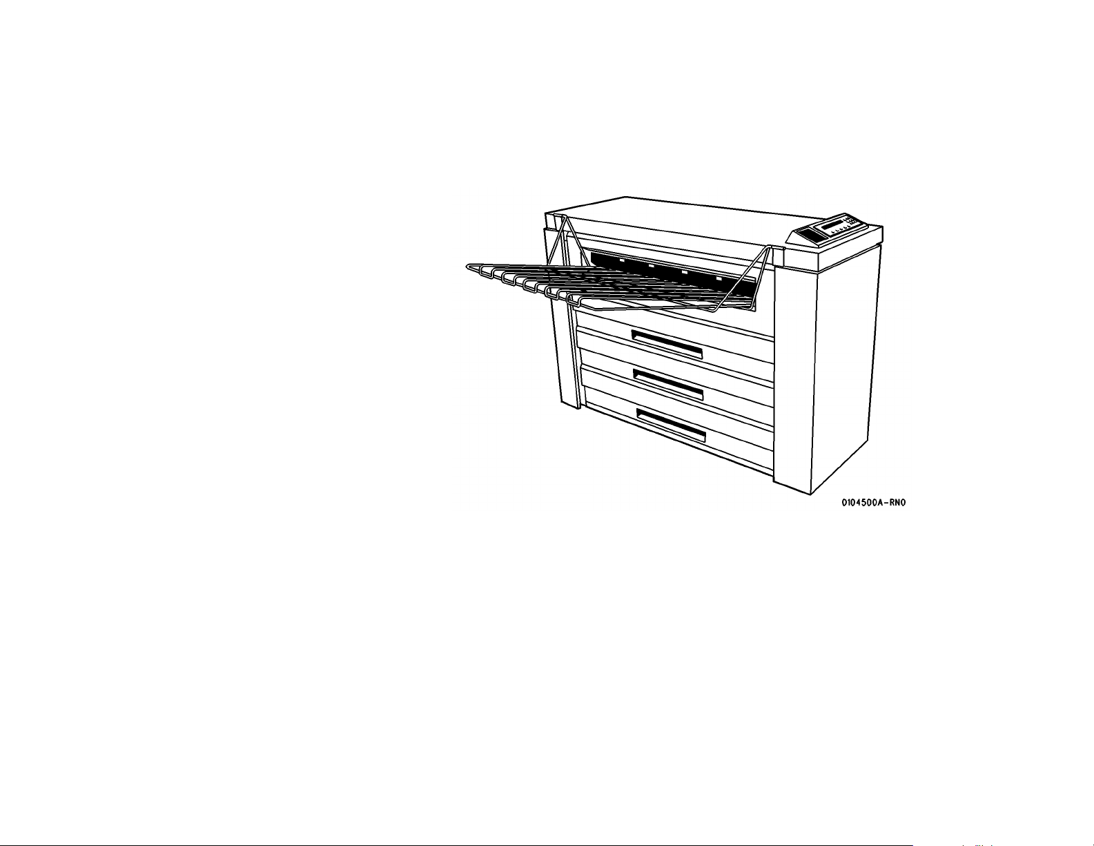
8825/ 8830 Pri nter
Service Manual
THE DOCUMENT COMPANY
XEROX
701P15051
January 2002
CAUTION
Cert ain components in the 8825/ 8830 Printer are
susceptible to d amage from electrostatic discharge. Observe all ESD procedures to avoid component damage.
Page 4

NOTICE
While every care has been taken in the preparation of this manual, no liability will be ac cep ted b y Xero x Cor pora tion a rising out o f any ina ccu racie s or
omissions.
NOTICE
All service documen tation is suppli ed t o Xe rox ex ternal cus tom ers for informational purposes only. Xerox service documentation is intended for use by
certified product trained service personal only. Xerox does not warrant or
represent that such documentation is complete, nor does Xerox represent
or warrant that it will notify or provide to such customer any future changes
to this documentation. Cust omer performed service of equipment, or m odules, components or parts of such equipment may affect the warranty
offered by Xerox with respect to such equipment. You should consult the
applicable warranty for its terms regarding customer or third party provided
service. If the cust om er serv ices suc h equipment, modules, c om ponents or
parts thereof, the customer releases Xerox from any and all liability for the
customer actions, and the cust omer agrees to indemnify, defend and hold
Xerox harmless from any third party claims which arise directly or indirectly
from such service.
Prepared by:
Xerox Corporation
800 Phillips Road
Bldg. 845-17S
Webster, New York 14580-9791
USA
© 1998, 1999, 2000, 2001, 2002 by Xerox Corporation. All rights reserved.
Xerox®, XES®, AccXES®, and The Document Company®
are trademarks of Xerox Corporation.
Xerox product names mentioned in this publication are trademarks of the
XEROX CORPORATIO N.
Page 5

About this Manual ........................................................................................................... iii
Organization....................................................................................................................iii
How to Use This Manu al ............ .... .... ... ........................... ........................... .................... iv
Repair Analysis Procedures (RAPs) ............................................................................... v
Repair / Adjustme nt Proc e du res .... .... ... .... ............... ................ ............... ........................ v
Introduction
8825/8830 Printer
01/02
i
Introduction
Page 6

Introduction
01/02
ii
8825/8 83 0 P rin te r
Page 7

About this Manual
This manual is part of a documentation system that includes the training.
This manual contains Repair Analysis Procedures (RAPs), Repair Procedures, Adjustment
Procedures, Parts List, Diagnostic Procedures, Installation Procedures, Wiring Data and
BSDs.
This m anual will enable t he Servic e Repres entative to repai r the 88 25/8830 p rinters. Those
service procedures affected by the 8825 configuration differences will be identified using the
8825 product name or Tag number .
Organization
This manual consists of eight sections. The title and description of each section are listed
below.
Section 1. - Service Call Procedures
This section contains the following:
• Call Flow Procedure
• Initial Actions/ System Checks
• Print Defect Isolation Procedure
• Workstation Checkout Pr ocedure
• Status Code Entry Chart
• Message Di splay Entry C hart
• Maintenance Procedures
• Callback
• System Checkout/ Final Action
Call Flow Proced ur e
The Call Flow Procedure is a list of activities to be perfor med on each service call.
Initial Actions/ System Checks
This proce du re is de si gn ed to iden ti fy an d cla ssi f y the pr o bl em and to refe r you to th e app rop r iate RAP in order to repair the problem. When the problem has been repaired, perform the Final
Action.
Print Defect Isolation Procedure
This proced ure directs the CSE to make test prints, perfo rm test procedures to identify the
cause of a print defect.
8825/8830 Printer
Workstation Checkout Procedure
This procedure is designed to ensure that the printer is correctly set up to run and communicate with other elements. It consists of a series of connection checks, configuration test prints,
PING tests, and tests made from a laptop PC.
Status Code Entry Chart
This ta ble prov ides a li st of stat us cod es, a des criptio n of the p roble m, the com ponen ts tha t
are affected, RAPs that may resolve the pr oblem, a s well as BSD references and Parts List references.
Message Display Entry Chart
This table contains a list of messages that may be generated by the printer, their cause, clearance procedures , and BSD references.
Maintenance Procedures
The Maintenance Procedures identifies functional checks and cleaning operations that must
be performed on every Normal Call. It also identifies those activities that can be performed as
needed or as scheduled.
01/02
iii
About this Manual, Organization
Introduction
Page 8

Callback
This service is performed when the CSE has been called back to correct a problem that was
thought to have been recently corrected. The Callback is a short procedure performed on only
that subsystem that caused the original service cal
System Check out / Fina l Action
This p rocedure is used to verify that the printer is operating correct ly after a repair, and that the
correct steps are taken to close out a service call.
Section 2. - Repair Analysis Procedures (RAPs)
This s ection conta ins t he Repa ir An alysis Proc edures (RAP s) ne cessa ry to r epair the f aults.
When using a RAP, always exit the procedure when the fault is fixed. Do not perform the
remaining steps.
Section 3. - Image Quality Repair Analysis Procedures (RAPs)
This s ection contai ns th e Rep air An alysis Proced ures (RAPs ) nece ssar y to r epair t he im age
quality faults. Refer to "How to Use the Image Defect Definitions" to compare the image defect
to the definitions. Once you have determined the definition that best describes the defect, go to
the sec tion cont ents page to find the appropr iate RAP. When using a RAP, always exi t the procedure when the fault is fixed. Do not perform the remaining steps.
Section 4. - Repair / Adjustment
This section contains the repair and adjustment procedures for the 8825/8830 printers.
Section 5. - Parts List
This section contains the detailed Parts List for the 8825/8830 printers.
How to Use This Manual
The Service Call Procedures will direct you to the appropriate Section of the Servic e Manual.
You should begin the service call with the Initial Actions/ System Checks Procedure. From
there, you wil l be r ef err e d to either Section 2, St at us Ind i c at or R APs, Sec tion 3, Image Qual ity
RAPs, or Section 7 BSDs.
If you are sent to Section 3, compare the image defect to the print quality definitions. Once you
have determined the definition that best describes the copy defect, go to the section contents.
The section contents will direct you to an image quality RAP. The RAP has a list of probable
causes and corrective actions. From these RAPs you may be referred to other sections of the
manual to make checks, Adjustments, or to replace parts.
When you have made a Repair , always go to the Call Flow Procedure to finish the call.
Section 6. - General Procedures
This se ction contain s Diagnost ic Procedu res, Install ation Proc edures, and G eneral Info rmation, which includes Product Spec ifications for t he 8825/8830 printers.
Section 7. - Wiring Data
This section contains the BSDs.
Introduction
Organization, How to Use This Manual
01/02
iv
8825/8 83 0 P rin te r
Page 9

Repair Analysis Procedures (RAPs)
A RAP is either a table of faults and possible solutions, or a series of steps designed to lead
you to the ca use of a pro blem . In ea ch step , yo u wi ll perfo rm an a ctio n or ob ser ve a n oc currence. For fa ult t ree RAP S, at each step, a stat emen t is m ade tha t ha s a Yes (Y) o r No ( N)
answer.
If the answe r is N O, p erform the a ctio n following th e NO . If th e a nsw e r is YES , pro c ee d to th e
next step.
When several items are listed, perform them in the order listed.
Proceed through the steps only until the observed problem is isolated and solved. Then eva luate the unit f or prope r performance. I f a f u rther de fe ct is observ ed , g o to th e ap propria te RAP
and perform the steps it contains un til the ad ditiona l fault is located and repaired.
Repair / Adjustment Procedures
The repair proc ed ur e s provide de t ai le d steps on how to remov e an d replace com p onents. The
adjustment procedures provide detailed steps on how to check and adjust components. Some
units hav e bee n m odi fied by v ari ous d esi gn chan ges . Ea ch c hang e or mo dific at ion i s lab el ed
with a Tag/ MOD (modification) number. The Tag/ MOD numbers are identified in the Change
Tag/ MOD Index in Section 6 of this Service Manual.
When a modification affects how a particular procedure is performed, the procedure or steps
are ide ntified with either a W/ Tag/ MOD or a W/ O Tag/ MOD statement. Each procedure or
step that is affected by a modification is identified with the statement, W/ Tag/ MOD, followed
by the modification number. The W/ in the sta tement in dicates th at this step m ust be performed on units that are assembled with
When the procedure or steps are not affected by a particular modification, they are identified
with th e sta teme nt, W/ O Tag/ MOD, fo llowe d by the mo dificat ion numb er. The W/ O in the
statement indicates that this step must be performed on units assembled without
modification.
that specific modification.
that s pecific
8825/8830 Printer
01/02
v
Introduction
Page 10

Introduction
01/02
vi
8825/8 83 0 P rin te r
Page 11

Introduction ..................................................................................................................... 1-3
Call Flow
Call Flow Procedure........................................................................................................ 1-5
Initial Actions/Systems Checks....................................................................................... 1-5
Print Defect Isolation Procedure ..................................................................................... 1-6
Workstation Checkout Procedure ................................................................................... 1-6
Status Code Entry Chart ................................................................................................. 1-7
Message Disp la y Entr y Char t..... .... .... ... ................ .......................... ................ ................ 1-11
Maintena nce Pro ce du res ... .... .... .... .... .......................... ................ .......................... ......... 1-1 2
Callback .......................................................................................................................... 1-15
System Checkout / Final Action
System Checkout / Final Action ...................................................................................... 1-17
1 Service Call Procedures
8825/8830 Printer
01/02
1-1
Service Call Proce dure s
Page 12

Service Call Proce dure s
01/02
1-2
8825/8 83 0 P rin te r
Page 13

Introduction
The Service Call Procedures are designed to assist the Service Representative to identify
printer faults, perform the necessary corrective action and perform the correct Maintenance
Procedures. The Service Call Procedures are designed to be used with the Printer Service
Manual and is the entry level for all service calls.
• Call Flow Procedure - The Call Flow Procedure is a list of activities to be performed on
each service call.
• Initial Actions / System Checks - This procedure is designed to identify and classify the
printer problem an d to refer you to the appro priate RAP in order to repair the pro blem.
When the problem has been repaired, perform the System Checkout / Final Action.
• Print Defect Isolation Procedure - This procedure directs the CSE to make test prints, perform test procedures to identify the cause of a print defect.
• Workst a tion Ch ecko ut Pro ced ur e - Th is proc ed ure i s des ig ne d t o ensur e that th e pri nt er is
correctly set up to run an d communica te with other e lements. It c onsists of a se ries of
conne ction che cks, con figurati on test prints, P ING test s, and t ests mad e from a laptop
PC.
• Status Code Entry Chart - This table contains a list of Status Codes, th eir related components, the corre s pond ing R AP (Rep air A nal ysis Pr oced ure ), B SD (B loc k Sc hema tic Diagram), Component Code and Parts List reference. The chart is designed to direct you to
the appropriate Clearance Procedure. When the Status Code problem has been repaired,
refer to the Call Flow Diagram and continue the Service Call.
• Message Display Entry Chart - This table contains a list of messages that may be generated by the printer, their cause, clearance procedures, and BSD references.
• Mainte nanc e Pro ced ures - This ta ble co nt ains a list of m essa ges that may be gener ate d
by the p rinter, their cause, clearance pr ocedures, and BSD references.
• Callback - This service is performed when the CSE has been called back to correct a
problem that was thought to have been recently corrected. The Callback is a short procedure performed on the subsystem that caused the original service call.
• System Checkout / Final Action - The purpose of this procedure is to record the media
feet count and to make a record in the machine l og book of the service activities that were
perfor med. Th e Final A ction is des igned to ensur e that t he prin t is tra nsporte d cor rectly
and to ensu re t h at im ag e quality is wi th in spe cification.
8825/8830 Printer
01/02
1-3
Service Call Proce dure s
Introduction
Page 14

Service Call Proce dure s
Introduction
01/02
1-4
8825/8 83 0 P rin te r
Page 15

Call Flow Procedure
Procedure
Perform the following:
1. Initial Actions.
There h as be en more t h an 5 custo me r w or k da ys o r 50 0 feet (150 met ers) since t he la st
service call.
YN
Perform the following:
1. Perform the Subsystem Checks for the subsystem that caused the problem.
2. System Checkout \ Final Action
Perform the following:
1. Mainte na nc e P ro ce dure for all su bs ys tems.
2. System Checkout / Final Action.
Initial Actions/Systems Checks
1. Ask the operator to try to duplicate the pr oblem.
2. Ask the operator to cancel all of the prin t jobs in the print queue.
3. Review the lo gbook for previous service on the system.
4. Check the Recent Fault Log for trends:
a. With a Controller - Print out the configuration sheet through the Utilities Menu. The
last 25 faults are listed on the upper-right side of the sheet.
b. Withou t a Controller - Ente r [0391]. The display will scro ll through the er ror codes
two at a time.
5. Analyze the frequenc y of the fault codes and refer to the Status Code Entry Chart to troubleshoot the problem:
a. C or E codes should occur no more frequently than once per 1000 linear feet.
b. All Cutt er fau lt s shou ld occ ur no more fre que ntl y tha n on ce per 10 ,00 0 li ne ar fee t.
NOTE: E4-09, Cx-04, and Cx-05 are out-of-media codes and will occur once per 500 linear
feet. A lso , 001 an d 002 co de s are po we r on/of f. Qu esti on the ope rator if the fa ul ts are ex ces sive.
6. Record the readings from the media length counter.
NOTE: Perform each of the following steps in sequence, unless directed elsew here.
7. If there is a fault indicator displayed, determine the type of fault.
• If a status code is displayed, go to the Status Code Entry Chart in this Section.
• If there is a message displayed, go to the Message Display Entry Chart in this Sec-
tion
8. If ther e is a print qu alit y problem , go to th e Print Def ect Is olation Proced ure in this Section.
9. If the Printer Control Panel is blank, go to OF-1 Control Panel RAP in Section 2 of this
servic e manual.
10. If the Printer Control Panel displays numbers during printer warm up, go to
svc.8830prt.2974 in Section 2 of this service manual.
11. If the customers lights flicker when the machine is turned on, go to OF-3 Fuser Ballast
RAP.
8825/8830 Printer
01/02
1-5
Service Call Proce dure s
Call Flow Procedure, Initial Actions/Systems
Page 16

Print Defect Isolatio n Procedure
Procedure
1. Go to Special Tests 0955 i n Sec tion 6 of thi s serv ice ma nual. Selec t opti on 5 (6 00 mm
print length on 36 inch wide paper) and make an internal test print.
2. If the defec t i s sti ll pr esen t, go to Print Quality Initialization Procedure in Section 3 of this
servic e ma nual.
3. Go to Workstation Checkout Procedure located in this Section.
Workstation Checkout Procedure
Initial Actions
1. Ensure that all connectors are seated correctly at the Controller.
2. If 8825 /8830 DDS c onfigurati on, ensure that t he SCSI cabl e from the Sca nner is con nected to the scanner connector on the Controller.
3. The Conf igura tion Test Print prov ides trou blesho oting in forma tion th at will be use d later.
Ensure that the communication parameters are set correctly.
Procedure
NOTE: Do each of the steps in sequence, unless directed otherwise.
1. Ask the customer to print a different file from the workstation. If the file prints OK, then the
original file might be corrupt.
2. If the work s t at io n is co nnected t o a netw ork, go to 3.. Otherwise, go to 5..
3. Ask the customer to obtain the IP address of another device on the network. Ask the customer to go to the DOS prompt and to use the PING function to test the connection to the
other device. If the PING test is successful, then go to 4.. Otherwise, notify the customer
that there seems to be a network problem.
4. Obta in the IP addres s for th e Cont roller from th e Conf iguratio n Test Print. As k the Customer to use the PING function to test the connection to the Controller. if the test is successful, then go to step 5. Otherwise, go to FRU (Field Replaceable Unit) Test in Section
2 of the Controller Servi c e Manual.
5. Connect the laptop computer to the parallel port on the Controller. Open the Document
Submiss ion Tool. Inse rt th e te st fil e disk in th e la pt op . Se nd a test file to the Prin te r. if the
defect is present, go to FRU (Field Replaceable Unit) Test in Section 2 of the Controller
Servic e Manual. O therwise , ask the cus tomer to rel oad the pri nt drivers. If the probl em
still ex is ts , t he re co uld be a defect i ve cab le .
Service Call Proce dure s
Print Defect Isolation Proced ur e, Wor kst atio n Che ck-
01/02
1-6
8825/8 83 0 P rin te r
Page 17

Status Code Entry Chart
T able 1 Stat us Code Entry Chart
Status
Code
C1-01
C2-01
C3-01
No
RAP
C1-04 Media registration sensor
C1-05
C2-05
C3-05
No
RAP
C3-06
No
RAP
C3-07
No
RAP
Position sensor error
The Roll 1, 2, or 3 position
sensor did not actuate or
deactuate.
error
The media sensor did not
actuate or deactuate when
feedi ng from roll 1, 2, or 3.
Motion sens or error
Motion was not detected or
the media stopped moving
when feeding from ro ll 1, 2, or
3.
Roll 2 pos ition sen sor error
8825 with Tag/MOD 90
Media was not detecte d at the
Roll 2 position sensor when
feeding from roll 3.
Roll 1 position sensor error
Media was not detecte d at the
Roll 1 position sensor when
feeding from Roll 3.
Description Components BSD
Roll 1 position sensor
(Q1)
Roll 2 position sensor
(Q2) 8825 with Tag/
MOD 90
Roll 3 position sensor
(Q3)
Main PWB (A3)
NOTE: The se nsors a re
interchangeable.
Media registration sensor
(A21Q1)
Main PWB (A3)
Driver PWB
Registration Rolls
Transport Driver Motor
Motor Driver PWB
Roll 1 motion sensor
(Q4)
Roll 2 motion sensor
(Q5) 8825 with Tag/MOD
90
Roll 3 motion sensor
(Q6)
Main PWB (A3)
Driver PWB
Motor Driver PWB
Media Fe ed Ro lls
Media Fe ed Clu tc h
Media Feed Drive Motor
NOTE: The sensors
and the clutches are
interchangeable.
Roll 2 position sensor
(Q2) 8825 with Tag/MOD
90
Main PWB (A3)
Roll 1 position sensor
(Q1)
Main PWB (A3)
RefPLRef
BSD
PL
7.2
7.1
BSD
PL
7.3
1.1A
BSD
7.4
BSD
8.1PL8.2
PL
1.1A
PL
8.3
BSD
PL
7.2
7.1
BSD
PL
7.3
1.1A
BSD
PL
7.4
7.2
BSD
7.1
BSD
7.3PL7.1
PL
1.1A
BSD
7.2PL7.1
PL
1.1A
Status
Code
C1-09
C2-09
C3-09
No
RAP
C1-19
C2-19
C3-19
No
RAP
C1-29
C2-29
C3-29
No
RAP
C1-39
C2-39
C3-39
No
RAP
C1-59
C2-59
C3-59
RAP
C4-24
No
RAP
C4-34
No
RAP
Table 1 Status Code Entry Char t
Description Components BSD
Firmware error
This is a firmware problem.
Press power off (0) then
power on (1). If problem persists, replace the firmware.
This is a Firmware prob le m
This is a firmware problem.
Press power off (0) then
power on (1). If problem persists, replace the firmware.
This is a Firmware prob le m.
This is a firmware problem.
Press power off (0) then
power on (1). If problem persists, replace the firmware.
This is a Firmware prob le m.
This is a firmware problem.
Press power off (0) then
power on (1). If problem persists, replace the firmware.
Light reflecting off of a
piece of media or from rear
of drawer or a baffle.
Regi stration sensor error
The cut sheet does no t reac h
the med ia registration sensor
in time.
Sheet feed sensor error
The sheet feed sensor deactuated too early while making
a print. The operator may
have removed the cut sheet
media.
Roll 1 position sensor
(Q1)
Roll 2 position sensor
(Q2); 8825 with Tag/
MOD 90
Roll 3 position sensor
(Q3)
Main PWB (A3)
Media registration sensor
(A21Q1)
Main PWB (A3)
Registration Rolls
Transport Drive Motor
Transport Motor Driver
PWB
Cut Sh eet Feed Clut ch /
Rolls
Driver PWB
Sheet feed sensor (Q2)
8825 with Tag/MOD 90
Main PWB (A3)
RefPLRef
PL
1.1A
PL
1.1A
PL
1.1A
PL
1.1A
BSD
PL
7.2
1.1A
BSD
PL
7.3
7.1
BSD
7.4
BSD
8.1PL8.2
PL
1.1A
PL
7.2
PL
8.3
BSD
8.1PL8.4
PL
1.1A
8825/8830 Printer
01/02
1-7
Service Call Proce dure s
Status Code Entry Chart
Page 18

Status
Code
C4-49
No
RAP
E2-01
No
RAP
E2-09
No
RAP
E2-11
No
RAP
E4-01
No
RAP
E4-02
No
RAP
E4-03
No
RAP
E4-04
No
RAP
T able 1 Stat us Code Entry Chart
Description Components BSD
This is a Firmware problem
This is a firmware problem.
Press power off (0) then
power on (1). If problem persists, r eplace the firmware.
Media registration sensor
error
The me dia trail edge jamm ed
in the media registration sensor area.
This is a Firmware problem
This is a firmware problem.
Press power off (0) then
power on (1). If problem persists, r eplace the firmware.
Registration sensor error
The media registration sensor was detected to be actuated when the machine
powered up.
Media exit sensor error.
The logic detected that the
media exit sensor (Q3) was
actuated at the wrong time.
Indic ating that t he media t rail
edge is jammed in the area.
Media exit sensor error
Lead edge of media did not
reach the media exit switch in
time.
Stripper finger jam switch
error
The stripper finger jam switch
was actuated during run.
Stacker Full
The Stacker Full Sensor was
actua ted during a r un or was
detected to be actuated when
the machine powered up.
RefPLRef
PL
1.1A
Media registration sensor
(A21Q1)
Main PWB (A3)
Media registration sensor
(A21Q1)
Main PWB (A3)
Media exit sensor (Q3)
Main PWB (A3)
Exit Drive Pulley, Belt,
Drive Rolls and Idler
Rolls
Transport Drive Motor
Driver PWB (A2)
Media exit sensor (Q3)
Main PWB (A3)
Fuser Drive Motor
Heat Roll
Transfer/Detack
Corotron
Fabric Guid e
Stripper finger jam switch
(A23S1)
Main PWB (A3)
Stripper Finger Damaged
Stacker Full Sensor PL
BSD
8.1PL8.2
PL
1.1A
BSD
8.1PL8.2
PL
1.1A
BSD
PL
10.3
8.4
PL
1.1A
BSD
PL
8.1
8.1
BSD
10.3PL8.4
PL
1.1A
PL
9.4
PL
10.1
BSD
10.3PL10.4
PL
1.1A
14.1
Status
Code
E4-09
No
RAP
E4-11
No
RAP
E4-12
No
RAP
E4-13
No
RAP
E4-14
No
RAP
E5-03
No
RAP
E5-04
No
RAP
E5-05
No
RAP
E5-06
No
RAP
Table 1 Status Code Entry Char t
Description Components BSD
This is a Firmware prob le m
Press power off (0) then
power on (1). If problem persists, replace the firmware.
Media exit senso r error
The media exit sensor was
detect ed t o b e ac tuat ed when
the machine powered up. This
requires the media exit area to
be opened, and the media to
be removed.
Sheet feed sensor error
The sheet feed sensor was
detect ed t o b e ac tuat ed when
the machine powered up. This
requires the media exit area to
be opened, and to be
removed.
Stripper finger jam switch
error
The stri pper fi nger jam switc h
was actuated at power on.
Media buckle sensor err or
The media buckle sensor was
detect ed t o b e ac tuat ed when
the machine powered up. This
requires the media exit area to
be opened, and the media to
be removed.
Top cover interlock switch
error
The top cover was opened
during print.
Cutter cover interlock
switch er ror
The cutter was opened during
print.
Feed shelf interlock switch
error
The sheet feed shelf was
opened during print.
Front door interlock switch
error
The front door was opened
during print.
Media exit sensor
(A23S1)
Main PWB (A3)
Sheet feed sensor
(A21Q2) 8825 with Tag/
MOD 90
Main PWB (A3)
Stripper finger jam switch
(A23S1)
Main PWB (A3)
Media buckle sensor
A21Q5)
Main PWB (A3)
Fabric Guide Position
Top cover interlock
switch (S26)
Driver PWB (A2)
Cutter cover interlock
switch (S1)
Driver PWB (A2)
Feed shelf inte rlo c k
switch (S29)
Driver PWB (A2)
Front door interlock
switch (S21)
Driver PWB (A2)
RefPLRef
PL
1.1A
BSD
10.3PL8.4
PL
1.1A
BSD
8.1PL8.4
PL
1.1A
BSD
10.3PL10.4
PL
1.1A
BSD
4.1PL8.4
PL
1.1A
BSD
1.3PL14.5
PL
1.1A
BSD
1.3PL7.6
PL
1.1A
BSD
1.2PL14.3
PL
1.1A
BSD
1.3PL14.3
PL
1.1A
Service Call Proce dure s
Status Code Entry Chart
01/02
1-8
8825/8 83 0 P rin te r
Page 19
T able 1 Stat us Code Entry Chart
Status
Code
E6-00 F ront door interlock switc h
E6-01 F ront door interlock switc h
E7-01 Communication error
E7-02
No
RAP
E9-XX Software shutdown
Fx-xx Refer to the Folder Service
J1-01
No
RAP
error
The C button was pressed
while a pr int was be ing made
in the roll feed mode. An operator induced soft shutdown
results in a complete print
being ma de. Th e l eft sid e do or
must be opened and then
closed.
error
The Exit button was pressed
while a pr int was be ing made
in the roll feed mode. An operator-induced hard shutdown
result s in a partial print be ing
made. The left side door must
be open ed and th en closed.
The IO T is un able to com municate with the Controller. The
IOT Off-Line and Media
menus will still function, but
cannot print from the Controller or network.
Printer message display
error
A required message is not
available in the language
EPROM. Update the language EPR OM.
This error is of unknown
cause. Please contact Software en gi ne er i ng .
Manual for all F-codes.
Toner sensor error
Out of t oner .
Description Components BSD
RefPLRef
Instruct the customer as
to the appropriate time to
press “C”
Instruct the customer as
to the appropriate time to
press “Exit”
Go to E701 RAP i n 8830
Controller Service Manual.
Language EPROM BSD
2.1
Toner sensor (A22Q1)
Main PWB (A3)
BSD
9.7PL9.9
PL
1.1A
Table 1 Status Code Entry Char t
Status
Code
J2-02
No
RAP
LL-00 Communication error
LL-02 Check sum test error
LL-05
No
RAP
LL-06
No
RAP
LL-07
No
RAP
LL-10
No
RAP
LL-11
No
RAP
Cartridge home sensor
error
Toner cartridge could not find
the home position.
Applies only to printe rs with a
bit mapped user interface
(FX).
Both message ROMs have
failed the checksum test
immed ia tel y after pow er up .
Fuser oil web error
NVM count of web encoder
pulses indicates the fuser oil
web has reac hed end of lif e.
Fuser oil web error
No encoder pulses are being
received from the fuser oil
web.
Fuser oil web error
Web Oiler Assembly connector not connected.
Module wrap-a round error
The paper transport assembly or the Xerographic module
is disconnected.
Communications error
Failed communications
between the Driver PWB (A2)
and the Mai n PWB (A3).
Description Components BSD
Cartridge Home Sensor
(A22Q2)
Main PWB (A3)
Cartri dge Drive Mo t o r
Cartri dg e D r iv e Gear
Web oiler motor
(A23MOT1)
Driver PWB (A2)
CONTROL EPROMS
Web oiler optical switch
(A23S2)
Web oiler motor
(A23MOT1)
Driver PWB (A2)
P/J 4, wiring harness,
pins
Driver PWB (A2)
NOTE: TAG 3 must be
installed for this code.
If not, disable the fault
detecti on using [10-35
Xerographic module
(A23)
Paper transport assembly (A21)
Driver PWB (A2)
Driver PWB (A2) (fuser
drive c ircuit)
Driver PWB (A2) (drum
drive c ircuit)
Main PWB (A3)
CAUTION: Fuser must
be up to temperature
before running motors.
RefPLRef
BSD
9.7PL9.9
PL
1.1A
PL
9.10
BSD
10.2PL1.1A
PL
9.6
BSD
10.2PL1.1A
PL
9.6
BSD
10.2PL10.4
PL
1.1A
BSD
7.5PL1.1A
BSD
PL
4.1
1.1A
BSD
4.3
8825/8830 Printer
01/02
1-9
Service Call Proce dure s
Status Code Entry Chart
Page 20
Status
Code
LL-12
No
RAP
LL-21
No
RAP
LL-22
No
RAP
LL-30
No
RAP
LL-41 Fuser error
LL-42
Thermal
Control
RAP
LL-43
Fuser
Over
Temperature
RAP
LL-44
Fuser
Too
Hot
RAP
Photoreceptor motor stall
fault
HVPS Charge error
The charge scorotron fault
signal was active for 1.5 seconds.
Transfer / Detack HVPS
Charge error
The transfer / detack corotron
fault signal was active for 1.5
seconds.
Cutter error
The cutter did not leave or
reach the home sensor. Turn
power off, then on.
The fuser did not reach 110
within one minute.
Fuser temperature error
The fuser roll temperature is
greater than the maximum
allowable temperature for
more than thirty seconds.
Maximum temperature is currently 348
Fuser temperature error
Fuser temperature has
exceeded the temperature
limit. The FUSER OPEN (L)
+26 VDC signal is low.
Fuser temperature error
Fuser tempera tu r e ex ce ed ed
420
PERATURE LIMIT signal
exceeds it’s limit.
Description Components BSD
° F (215° C). The TEM-
T able 1 Stat us Code Entry Chart
Drum drive motor
(A20MOT3)
Driver PWB (A2)
ADJ 8.4 Medi a Tran sp ort
Xerographic HVPS (A25)
Driver PWB (A2)
Scorotron
Xerographic HVPS (A25)
Driver PWB (A2)
Transfer/Detack
Corotron
Cutter ho m e se ns or
(A8Q1)
Driver PWB (A2)
Cutter Drive Motor
Fuser heat rod (HTR1)
°F
Thermistor assembly
(A23RT1)
Fuser power relay
(K1)Triac (Q1)
AC Power module (A1)
Driver PWB (A2)
Main PWB (A3)
Triac (Q1)
AC Power module (A1)
Driver PWB (A2)
° F (176° C).
Triac (Q1)
AC Power module (A1)
Driver PWB (A2)
Thermal fuse (A23F1)
Triac (Q1)
LVPS (A5)
Driver PWB (A2)
Main PWB (A3)
RefPLRef
BSD
4.3PL1.1A
PL
9.1
BSD
9.1PL1.3
PL
1.1A
BSD
9.8PL1.3
PL
1.1A
BSD
7.5PL1.1A
PL
7.8
10.1 PL
10.2
PL
10.4
PL
1.1A
10.1 PL
1.2A
PL
1.1A
10.1 PL
1.1A
PL
1.2A
PL
10.4
10.1
PL
1.2
10.4
10.1
PL
10.1
1.1A
Table 1 Status Code Entry Char t
Status
Code
LL-41 Fuser temperature error
LL-4F
No
RAP
LL-50
No
RAP
LL-51
No
RAP
LL-52
No
RAP
LL-53
No
RAP
LL-54
No
RAP
LL-55
No
RAP
LL-56
No
RAP
LL-57
No
RAP
Fuser was in the warm up
mode too long.
Fuser fault
Fuser was expected to be
warming but is was not.
Power supply error
26 VDC Bulk power supply
failure.
Power On Self T est fault
The internal RAM failed
POST.
Power On Self T est fault
or
Main PWB in stalled withou t
CONTROL EPROMS
The external RAM failed
POST.
Power On Self T est fault
IOT firmware checksum error.
Power On Self T est fault
An unknown device failed
POST.
Power On Self Test LVPS
fault
The +10 V FW R voltage was
detected to be off when it
should have been on.
Power On Self Test ADC/
DAC fault
The ADC/DAC failed POST
Power On Self Test SCC
fault
Description Components BSD
RefPLRef
Fuser heat rod (HTR1)
Fuser power relay (K1)
Triac (Q1)
Ballast resistors (R1 &
R2)
Fuser ballast power relay
(K3)
Driver PWB (A2)
Main PWB (A3)
Fuser power relay (1K1)
Fuser ballast power relay
(A1K3)
Fuser Triac (A1Q1)
Fuser he ater (A23H R 1)
LVPS (A5)
Driver PWB (A2)
Main PWB (A3)
Main PWB (A3) PL
Install the Control
EPROM
Main PWB (A3)
Install the Control
EPROM
Main PWB (A3)
Main PWB (A3) PL
LVPS BSD
Main PWB (A3)
Driver PWB (A2)
Main PWB (A3) PL
10.1 PL
10.2
PL
1.1A
PL
1.2A
PL
1.3
BSD
10.1PL1.2A
PL
10.2
BSD
1.2PL1.1A
PL
1.3
PL
1.3
1.1A
PL
1.1A
PL
1.1A
1.1A
1.2PL1.1A
PL
1.1A
1.1A
Service Call Proce dure s
Status Code Entry Chart
01/02
1-10
8825/8 83 0 P rin te r
Page 21
Status
Code
LL-58
No
RAP
LL-60
No
RAP
LL-61
No
RAP
LL-89
No
RAP
LL-90
Overtoned
Fault
RAP
LL-91
Undertoned
Fault
RAP
U1-01
No
RAP
T able 1 Stat us Code Entry Chart
Description Components BSD
Power On Self T es t
Extra “Return Value” from the
Operating System. Reboot
(Power off / Power On).
Power On Self Test NVM
Checksum fault
Recor d the exis ting NVM values. Ru n diagnos tic [036 0] to
reset NV M to the default v alues. Manually restore the
required NVM values.
Power O n S elf Test revi sion
level fault
Power the printer up in diagnostics and run [0360] to reset
NVM to default values.
This is a Firmware problem
This is a firmware problem.
Press power off (0) then
power on (1). If problem persists, r eplace the firmware.
Overtoned fault
Toner concentration of the
develo per material is too high.
Undertoned fault
Toner concentration of the
develo per material is too low.
Media counter error
Print counter is disconnected.
Install the Control
EPROM
Main PWB (A3)
Cartridge drive motor
(A22MOT1)
Cartridge home sensor
(A22Q2)
Toner sensor (A22Q1)
Main PWB (A3)
Cartridge drive motor
(A22MOT1)
Cartridge home sensor
(A22Q2)
Toner sensor (A22Q1)
Main PWB (A3)
Media co un ter
Main PWB (A3)
RefPLRef
1.1A
1.1A
3.1
PL
9.7
1.1A
9.7
PL
9.3
9.9
9.7 PL
9.9
PL
1.1A
BSD
3.1PL1.3
PL
1.1A
PL
PL
Message Display Entry Chart
Table 1 Message Display Entry Chart
MESSAGE DIS-
PLAYED
PRINTER IS WARMING UP (Continuously
displayed)
ADJUSTING THE
PRINT QUALITY (Continuously disp layed)
PLEASE CLOSE THE
MEDIA DRAWER X
(Refer to Note)
PLEASE CLOSE THE
CUT SHEET FEED
SHELF
PLEASE CLOSE THE
FRONT DOOR
PLEASE CLOSE THE
TOP DOOR
PLEASE CLOSE THE
CUTTER DRAWER
NVM FAULT CALL FOR
ASSISTANCE
Re-feed Roll 1 Re-feed roll 1
Re-feed Roll 2 Re-feed roll 2
Re-feed Roll 3 Re-feed roll 3
Flashing 1, 2, 3, 4, 5, 6
or 7
UNABLE TO CALIBRATE TONER SENSOR
TONER FAULT CALL
FOR ASSISTANCE
CAUSE CLEARANCE PROCEDURE BSD
No fuser heat - - - BSD
Toner dispense
problem
Drawer X read
switch is open.
Cut sheet feed
shelf interlock
switch (S29) is
open.
Front door interlock switch (S21)
is open.
Top cover interlo ck
switch (S26) is
open.
Cutter cover interlock sw itch (S1) is
open.
Corrupted data in
NVM.
problem.
problem.
problem.
Copier failed
power on self-tes t.
The sensor did not
calibrate when the
code [0921-6] was
entered.
Excessive toner
sensed problem.
Ref
10.1
- - - BSD
9.3
Refer to the display on the control panel
and follow the clearance procedure.
Refer to the display on the control panel
and follow the clearance procedure.
Refer to the display on the control panel
and follow the clearance procedure.
Refer to the display on the control panel
and follow the clearance procedure.
Refer to the display on the control panel
and follow the clearance procedure.
Press power off (0) then power on (1). If
problem persist run diagnostic program
[0363] or [0360]. If problem persist
replace the Control EPROMS.
Re-feed the media. If necessary, press
power off (0) then power on (1).
Re-feed the media. If necessary, press
power off (0) then power on (1).
Re-feed the media. If necessary, press
power off (0) then power on (1).
Press power off (0) then power on (1). If
problem persists, go to
svc.8830prt.2974.
Press power off (0), then power on (1).
If problem persists, go to LL-91 Under-
toned Fault RAP .
Press power off (0), then power on (1).
If probl em persists, go to LL-90 Over-
toned Fault RAP .
BSD
7.1
BSD
1.2
BSD
1.2
BSD
1.2
BSD
1.2
BSD
7.2
BSD
7.3
BSD
7.4
BSD
9.7
BSD
9.7
8825/8830 Printer
01/02
1-11
Service Call Proce dure s
Status Code Entry Chart, Message Display Entry
Page 22
Table 1 Message Display Entry Chart
ALL ROLLS ARE
EMPTY
NOTE: Substitute 1, 2, or 3 for X dep ending on which status code is displayed.
Media Registration
Sens or failed to
sense me di a.
Go to C1-04.
Maintenance Procedures
Table 1 Image Module
INTER
VAL
Nor-
mal
Call
Nor-
mal
Call
Nor-
mal
Call
As
Requir
ed
TASK RE ASON TASK ENA BLE R
Check, clean, or
repair spacing
wheels as
required.
Check and clean, if
required, the
scorotron.
Clean the image
bar.
Repair or replace
the sco rot r on/grid.
Contaminated, dirty or
worn spacing wheels or
drum ends cause print
quality defects.
Contaminated grid, bent
or contaminated pins.
Worn end blocks, are
also causes for scorotron
failure, which results in
print quality defects.
Contamination causes
print quality defects.
Contamination causes
print quality defects.
Clean or replace spacing wheels and
the end surface that the wheels ride
on.
WARNING
The scorotron pin arrays are very
sharp. Use care when handling the
assembly.
If contam inated , rem o v e sc oro t ro n
assembly and clean both sides of the
grid with a brush. Examine pins and
clean with brush Only if contaminated. Cleaning with a cloth can
deposit lint that will cause print quality problems.
Clean the image bar with a lint free
cloth an d len s cl eaner.
WARNING
The scorotron pin arrays are very
sharp. Use care when handling the
assembly.
Replace the grid and/or pin array.
Perform ADJ 9.2 Elect r osta tic
Series.
Service Call Proce dure s
Message Display Entry Chart, Maintenance Proce-
01/02
1-12
INTER
VAL
Table 2 Xerographic Module
TASK REASON TASK ENABLER
8825/8 83 0 P rin te r
Page 23

Nor-
Clean the xero-
mal
graphic module .
Call
Clean the erase
lamp.
Inspect the photoreceptor for damage.
Inspect components for vellum
contamination.
Inspect all seals
for damage.
Inspect the
Cleaner Blade for
damage.
Nor-
Check and clean
mal
or replace the
Call
Stripper Fingers.
Clean the Media
Guides.
Nor-
Clean/check the
mal
Fuser Roll fabric
Call
guide. Re pl ace th e
Fuser Roll.
Nor-
Check the fuser
mal
roll for lack of oil.
Call
Nor-
Inspect/clean the
mal
thermistor pad
Call
Table 2 Xerographic Module
Contamination can cause
print quality problems.
Contaminants can travel
to the LED bar and
scorotrons, which results
in prin t quality pro blems.
Fused toner on the bottom of the module can
cause j ams.
Contamination reduces
the effectiveness of the
lamp to discharge the
photore c eptor drum .
Contaminants from vellum
- Cleaner failure
- Contaminants to prints.
Vellum con taminatio n will
contam ina te an d plu g t he
cleaner auger at the
ends.
Bent stripper fingers may
cause feed out jams and
heat roll damage.
Contaminated or damaged media guides can
cause print quality
defects.
Smooth or worn fuser ro ll
loses ability to drive
media.
Contaminated fabric
guide causes too much
resistance to media
which results in jams/
deletions/wrinkles.
Too little oil can cause
media handling and offsetting print quality problems.
Contamination can cause
fuser heat problems.
Clean the toner from the housing and
cleaner blade with a vacuum cleaner.
NOTE: Ensure that the vacuum
cleaner does not co ntact the edge of
the cleaner blade that touches the
surface of the photoreceptor drum.
Perform the Photoreceptor Cleaning
Enhanceme nt p rocedu re in s ecti on 6.
Use cleaning solvent to remove any
fused toner from the bottom of the
module. R ep lace t he p ho tor ec ep tor if
damaged.
Clean the erase lamp with a brush or
dry lint free clot h.
Replace any damaged xerographic
module seals.
Replace the damaged or contaminated stripper fingers.
Clean the roll with film remover.
Clean the fabric guide with formula A
and film remover.
Perform diagnostic code 1033 every
time the oiler is removed.
Check remaining fuser web life
[1034] and adjust the web oi ler rate
[1032].
If the fuser roll is dry, refer to BSD
10.2.
Clean the thermistor pad with a brush
or dry lint free cloth.
Table 2 Xerographic Module
As
Check/clean the
Requir
photoreceptor.
ed
As
Check/clean the
Requir
cleaning blade.
ed
Replace with the
*Note 3
NOTE: 1. Ensure that the vacuum does not conta c t the edge of the cleaner blade that touc hes
the surface of the photoreceptor drum.
NOTE: 2. Wh e re p os s i b le , du s t th e d r u m a nd t h e c l ea nin g blade w i t h zi nc s tearate a w ay f rom
the xerographic module to prevent the charge scorotron from being contaminated. If the drum
and cleaning blade must be dusted while in the xerographic module, remove the charge
scoro tron. The zin c stearate will contaminate the charge scorotron and caus e print qual ity
defects.
NOTE: 3. Install the complete cleaning blade kit when installing a new photoreceptor.
new photoreceptor or as required.
30K ft.
Replace the fabric
9Km
guide.
30K ft.
Clean the inner
9Km
xerographic module comp onents.
INTER
VAL
Nor-
Clean the lower
mal
paper transports,
Call
turnaround baffle,
paper feed rolls.
Nor-
Clean the under
mal
side of the trans-
Call
port.
TASK REASON TASK ENABLER
Contamination/wear,
scratches, or chips can
generate print quality
problems.
Residual image, streaks,
drum scuffing can occur if
the blade is worn or contaminated.
Jams, de le tions, wrink les. Refer to REP 8.9
If the customer is running
a high percentage of vellum, outgassing of the
vellum contaminates the
cleaner auger and lower
baffle surface resulting in
poor cleaning and high
dirt contamination.
plugge d cleaner auger
T able 3 Media T ransport
Contaminates can cause
the me di a t o sl ip resul tin g
in print qu ality def ec ts .
Reduc e the ai rbo rne contaminants.
Inspect photoreceptor surface for
deep scratches, chips or excessive
wear. Repl ace photor eceptor if damaged.
Apply zinc stearate to the cleaning
blade and ph ot ore cep t or d r um. * Not e
2
Clean photoreceptor surface with
Xerox Film Remover if contaminated.
Apply zinc stear a te when surfa ce is
dry.
Vacuum cle an the clea ning blade .
*Note 1
Apply zinc stearate to the cleaning
blade and ph ot ore cep t or d r um. * Not e
2
Replace the blade if damaged.
Remove the fuser roll and photoreceptor t o enable access.
NOTE: Use caution not to touch or
damage cleaning blade or seals.
Vacuum the Xero Mod and A uger
and then clea n al l con taminated
areas with Film Remover.
Clean the transport with antistatic
fluid and a lint free cloth.
Clean the feed roller wit h Formul a A.
Va cu um cl ea n, th en wip e do wn wit h a
lint free cloth.
8825/8830 Printer
01/02
1-13
Service Call Proce dure s
Maintenance Procedures
Page 24
Nor-
Clean the transfer
mal
corotron
Call
Nor-
Empty the conden-
mal
sation r eclaim bot -
Call
tle.
25K ft.
Repair or replace
7Km
the transfer
corotron.
INTER
VAL
1st
Remove the drive
10K ft.
chain slack.
or 3K
m
40K ft.
Remove the drive
or 13K
chain slack.
m
INTER
VAL
Nor-
Brush the devel-
mal
oper from the
Call
Developer Seal
and lower edge of
the Developer
Housing back into
the Developer Mag
Roll and then
clean the Seal.
Nor-
Check that the
mal
developer housing
Call
is level.
Nor-
Check the canis-
mal
ter for proper rota-
Call
tion.
Nor-
Check the devel-
mal
oper drive s.
Call
Table 3 Media Transport
Improv e toner tra nsfer to
media.
Improve media tack.
Prevent the bottle from
overflowing.
Contamination causes
print quality defects.
Table 4 Media Feed
TASK REASON TASK ENABLER
Feedin g problems . Loosen the feed motor ha rdware to
Feedin g problems . Loosen the feed motor ha rdware to
T able 5 Developer Modu le
TASK REASON TASK ENABLER
Image quality problems
can occur.
If the developer is not
level, densit y may not be
uniform side to side .
If the cani ster i s no t ro tat ing correctly, the copies
will be light.
Worn gears will cause the
housing to move up or
down, which will cause
print quality defects.
Remove the transfer corotron. Clean
loose toner/debris with a brush. Use
only a water-dampened cloth to
remove contaminants from the extrusion.
NOTE: Some of the coating may
come off onto the cloth.
Empty the bottle into a sink.
Clean (same as the step above).
allow the spring to tension the chain.
Tighten the hardware.
allow the spring to tension the chain.
Tighten the hardware.
Clean as re qu ire d.
Developer material s hould not be uniform from end to end. Check the level
of the copier.
Check t h e dry in k di sp ense motor fo r
binding. Check that the cartridge is
locked i n the driv e hub.
Check the gears fo r worn or brok en
teeth; replace the gears, if necessary.
Ensure that the drive coupling is
engaged.
Table 5 Developer Module
Nor-
Check, clean, or
mal
replace the devel-
Call
oper housing
spacin g wheels, as
required.
30K ft.
Check the trickle
9Km
tube and toner Y
tube for obstruction.
30K ft.
Check the pres-
9Km
sure equalizing
tubes.
INTER
VAL
Nor-
mal
Call
INTER
VAL
Nor-
mal
Call
Nor-
mal
Call
INTER
VAL
Nor-
mal
Call
INTER
VAL
Nor-
mal
Call
TASK REASON TASK ENABLER
Clean the covers. Cus tomer satisfaction . Formul a A an d antis tatic f luid on the
TASK REASON TASK ENABLER
Check the cam for
lubrication.
Clean the cutter. To ensure a straight,
TASK REASON TASK ENABLER
Clean the media
drawer.
TASK REASON TASK ENABLER
Check and replace
the Ozone Filter if
necessary.
Contaminated or worn
spacing wheels will cause
print quality defects.
An obstructed Y tube or
trickle tube will clog the
cleaning/trickle system.
Increased contamination
due to poor air flow in the
develop er housing.
Table 6 Covers
T able 7 Cut ter
To ensure the correct cutter operation. The cutter
will n ot p rovide a stra ight
cut.
smooth cut on the lead
edge of the media.
T able 8 Media Drawers
Customer satisfaction. Clean the media dust and contamina-
Table 9 Ozone Fil ter
To ensure correct air flow
through machine, and to
keep heat that is generated to a minimum.
Clean or replace spacing wheels.
Clean as required.
Remove developer hous in g. R em ov e
and vacuum tubes, vacuum lower
holes for toner.
and cut sheet feed-in shelf.
Place a l ig ht fil m of lubri ca ti on on the
cam surface.
Vacuum the medi a dust and co n tam ination from the cutter blade area.
tion from each of the media drawers
with a vacuum cleaner.
Check th eOzo ne Fil ter at 40 K print s,
clean or replace as required. Replace
the Ozone Filter at 120K pr ints.
Service Call Proce dure s
Maintenance Procedures
01/02
1-14
8825/8 83 0 P rin te r
Page 25

Callback
Procedure
1. Perform the Subsystem Checks for the subsystem that caused the problem.
2. Functional Checks:
a. Perform the Initial Actions.
b. Check the Recent Faults listing (see Section 6 - under System Information). If any of
the faul ts desc ribe d i n that se ctio n ar e lis ted, tak e the rec omm end ed step s t o cle ar
the fault.
c. Replace any part or supply that is past its lif e.
3. Perform th e Final Action. Do Not perform the Maintenance Procedures.
8825/8830 Printer
01/02
1-15
Service Call Proce dure s
Page 26

Service Call Proce dure s
01/02
1-16
8825/8 83 0 P rin te r
Page 27

System Checkout / Final Action
Procedure
Enter diagnostic mode and make three (3) prints of internal test pattern from the controller (if
present). If a controller is not present, print [0955-5] from the IOT. Prints are delivered to the
exit tray.
YN
Go to the Initial Actions to begin yo ur repair.
Evaluate the prints using Print D efec ts in Section 3. The print quality is acceptable.
YN
Go to the Print Defects in Section 3 an d go to the ap propriate print quality RA P.
Perform the following:
1. Clean the exterior of the printer and provide print samples to the customer.
2. (Figure 1 ): Fill out the Service Call Report form including:
Enter th e Prin te r M en u, a nd s cr oll t o Bil lin g M ete rs . E nte r B ill in g Me te r a nd re c ord M et er
A and Meter B readi ngs on the S ervice Call Report form.
3
Enter the re ading
from the Media
Counter here
3. Record all activities in the Servic e Log.
4. Record the Print Count Readings on the Ser vice Cal l Report.
5. Give appropriate credit to the Customer.
8825/8830 Printer
1
Access the Control
Panel me nu an d reco rd
the Meter A reading
Figure 1 Recording the Print Count Readings
2
(8830 printer only:) Access
the Control Pa nel menu and
record the Meter B reading.
01/02
1-17
Service Call Proce dure s
System Checkout / Final Action
Page 28

Service Call Proce dure s
System Checkout / Final Action
01/02
1-18
8825/8 83 0 P rin te r
Page 29

Repair Analysis Procedures
C1-04/C2-0 4/ C3-0 4 R AP ...................... ........................... ............... ........................... ..... 2 -3
C1-59/ C2-59/ C3-59 RAP .............................................................................................. 2-4
LL-41/LL-45 Fuser Warm-up Fault RAP ......................................................................... 2-5
LL-42 Thermal Control RAP............................................................................................ 2-6
LL-43 Fuser Over Temperature RAP.............................................................................. 2-7
LL-44 Fuser Too Hot RAP............................................................................................... 2-8
LL-60/LL-61 NVM Fault RAP .......................................................................................... 2-9
LL-90 Overtoned Fault RAP............................................................................................ 2-10
LL-91 Undertoned Fault RAP.......................................................................................... 2-11
Other Faults
OF-1 Control Panel RAP................................................................................................. 2-15
OF-2 Power On Self Test (POST) RAP .......................................................................... 2-15
OF-3 Fuser Ballast RAP.................................................................................................. 2-16
Generic RAPs
Generic Clutc h RA P ............... ............... ................ .......................... ........................... ..... 2-17
Generic Sens or RAP.............. ........................... ........................... ............... .................... 2-1 8
Generic Swit ch RAP....... .... ................ ............... ........................... .......................... ......... 2-1 9
2 Status Indicator RAPs
8825/8830 Printer
01/02
2-1
Status Indicator RAPs
Page 30

Status Indicator RAPs
01/02
2-2
8825/8 83 0 P rin te r
Page 31

A
C1-04/C2-04/C3-04 RAP
NOTE: Roll x means Roll 1, 2, or 3.
The Media Drive Motor (MOT1, BSD 7.1) was trying to feed the Roll x Media for ward to the
registration p os it ion but the Media R eg is tr a ti on Sens o r ( A 21 Q 1, BSD 8.1) fa iled t o se nse th e
media.
Initial Actions
• Check the Media Roll (in the Drawer that was in use when the f ault occurred).
Table 1 Media Roll
Roll 1 BSD 7.2
Roll 2 BSD 7.3
Roll 3 BSD 7.4
• Check that the Drive Chai n, PL 7.2, is OK ( BSD 7.1).
Procedure
Enter DIAGNOSTICS (Gen eral Procedures). Enter [0703] (ROLL FEED M OTOR FOR-WARD)
and observe the Media Drive Motor. The Media Drive Motor runs.
YN
Check that the Media Drawers are closed. Check the operation of the Drawer Interlock
Switched as follows:
Enter [0713] for Drawe r 1
Enter [0714] for Drawe r 2
Enter [0715] for Drawe r 3
Each Drawer Interlock switch functions co rrectly.
YN
Go to BSD 7.1 and check the ci rcuit o f the Draw er Inte rlock Switch that does n ot
function correctly. Check that the actuating magnet is not missing.
Go to BSD 8.1. Enter [0917 and then enter [1] on the keypad. Observe the Transport Drive
Motor (A21MOT1). The Transport Drive Motor (A21MOT1) runs.
YN
Go to BSD 8. 1, NOTE 4, and check the resistances of the windings of the Transport
Drive Motor (A21MOT1). The resistances of the windings of the Transport Drive
Motor (A21MOT1) are O K.
YN
Replace the Transport Drive Motor (A21MOT1), PL 8.1.
Go to BSD 8.1, NOTE 2, and check the voltages at A24P1. The voltages at A24P1 are
OK.
YN
Check all wiring between A2P210 and A24P1. If the wiring is OK, replace the Driver
PWB (A2), PL 1.1A.
NOTE: Drive Motor PWBs (A24) and (A7), BSD 7.1, are identical and can be exchanged
with each other.
Replace the Drive Motor PWB (A24), PL 7.2.
Go to BSD 8.1. Enter [0803 and check the Media Registration Sensor. The Media Registra-
tion Sensor is OK.
YN
Check the circuit of the Media Registration Sensor (A21Q1).
Check for mechanical binding or broken parts in the area of the Registration Drive Rolls and
Pinch Rolls.
Go to BSD 7.1, NO TE 2 , an d ch eck th e res ista nc es o f the win ding s of th e Me dia Driv e
Motor (MOT1) The resistances of the windings of the Media Drive Motor (MOT1) are
OK.
YN
Replace the Medi a Drive Motor (MOT1) , PL 7.2.
Go to BSD 7.1, NO TE 1, and check the voltages at A7P1. The voltages at A7P1 are
OK.
YN
Check all wiring between A2P208 and A7P1. If the wiring is OK, replace the Driver
PWB (A2), PL 1.1A
NOTE: Drive Motor PWBs (A24), BSD 8.1, and (A7) are identical and can be
exchanged with each other.
Replace the Drive Motor PWB (A7), PL 7.2.
A
8825/8830 Printer
01/02
2-3
Status Indicator RAPs
C1-04/C2-04/C3-04 RAP
Page 32

C1-59/ C2-59/ C3-59 RAP
NOTE: C1, C2, C3 means Roll 1, 2, or 3.
The Media Drive Motor (MOT1, BSD 7.1) was trying to feed the Roll x Media for ward to the
regist rat i on p osit io n bu t the Posi ti on Sens or (Q1, Q2, or Q3 , BSD 7. 2, 7. 3, 7.4) se nse d tha t the
media jammed . Th e pro bl em may be caus ed by lig ht ref l ecti ng of f of med ia , the me di a dra wer,
or baffles an d returning to the media Position Sens or.
Initial Actions
• Check that the Roll 1, 2, or 3 (the Drawer that was in use when the fault occurred) Position Sensor Q1, Q 2, or Q3 is not blocked by a piece of media.
• Ensure that there are no strips or pieces of media in the area of the Position Sensor Q1,
Q2, or Q3.
Table 1 Media Roll
Roll 1 BSD 7.2
Roll 2 BSD 7.3
Roll 3 BSD 7.4
Procedure
Enter DIAGNOSTICS (Gen eral Procedures). Enter [0703] (ROLL FEED M OTOR FOR-WARD)
and observe the Media Drive Motor. The Media Drive Motor runs.
YN
Check that the Media Drawers are closed. Check the operation of the Drawer Interlock
Switched as follows:
Enter [0713] for Drawe r 1
Enter [0714] for Drawe r 2
Enter [0715] for Drawe r 3
Repair the Interlock Switch as required.
Check th e rea r of th e appro pri ate D rawe r an d the ba ffle s that ar e lo cate d aro und th e open in g
of the Positio n Sens or for s hinny o r reflec tive sur faces. If thes e condi tions ex ist co rrect th e
problem by painting the surfa c e with flat black paint or use a black mar k er to cover the surface.
Status Indicator RAPs
C1-59/ C2-59/ C3-59 RAP
01/02
2-4
8825/8 83 0 P rin te r
Page 33

LL-41/LL-45 Fuser Warm-up Fault RAP
NOTE: Go to BSD 10.1 whi le us in g t hi s RA P.
This RAP is used when the Fuser does not warm up when the control logic attempts to
increase the heat.
LL-41 is displayed when the Fuser heat does not increase to 110º F (43º C) within one minute.
LL-45 is displayed when the Fuser temperature is greater than 110º F (43 º C) but does not
reach the setpoint temperature within the specified time period.
Initial Actions
• Ensure that the following connectors are correctly seated:
1. Thermistor Assembly RT1J5 / A23P5
2. Thermal Fuse A23XF1
3. Xerographic Module A23J2 / A23P2
4. Fuser Heat Rod A23HR1P2 (blue wire)
5. Fuser Heat Rod A23HR1P1 (brown wire)
• Ensure that the correct Fuse r Heat Rod is installed.
• Check the wa ll ou tle t for co rrec t lin e vo lt ag e.
WARNING
Dangerous Voltage
Procedure
NOTE: After ent ering the code [1004], the Fuser Power Re lay, A1K1, and th e Fuser Power
LED, (A2CR15 without Tag 25 or A2CR31 with Tag 25) on the Driver PWB, are energized for
approximately five minutes.
Enter DIAGNOSTICS (General Procedures). Enter [1004] to test the operation of the Fuser.
After 10 seconds, the Fuser Heat Rod is still on.
YN
Switch off t h e pr in te r an d d is c onnect t he po w er c ord. Me as ur e t h e resistance of t he H e at
Rod as follows: Disconnect A23P1/A23J1. Connect the meter leads to A23J1-1 and
A23J1-3. The resistance is less than 30 Ohms.
YN
Check the wiring between A23J1 and t he Fuser Heat Rod (HR1). The wires have
continuity
YN
Repair the wires
A
B
Check for AC p ower from th e Fuse r Pow er Rela y as fo llows: Recon nect A 23P1/A 23J1 .
Set the meter to read AC voltage and connect the meter leads to A1K1-4 and A1K1-8.
Cheat the front door interlock. Connect the Power Cord and switch on the printer. Wait 10
seconds. AC power is present.
YN
Set the meter to read 26 VDC and connect the (+) meter lead to A1K1-1 and the (-)
meter lead to A1K1-0. Switch off, then switch on, the printer. 26 VDC is present.
YN
Check the Fuser Power Relay On signal from the Driver PWB, A2, as follows:
Connect the (+) meter lead to A2J213-1 and the (-) meter lead to A2J213-3.
26 VDC is present.
YN
PL 1.1A Replace the Driver PWB, A2.
Check and repair the wiring between the Driver PWB, A1, and the Fuser Power
Relay, A1K1.
Replace the Fuser Power Relay, A1K1, PL 1.2A.
Switch off the printer and disconnect the power cord. Check the following wires for continuity.
Table 1
From To Color
A1K1-8 A1Q1MT1-A WHT
A1Q1MT2-A A23P1-1 BLU
A1K1-4 A23P1-3 BLK & BRN
The wires have continuity.
YN
Repair the wires
Set the meter to read +2 VDC. Connect the (+) lead to A1Q1 -G (BRN wire) and the (-)
lead t o A1Q1-M T1 (WHT w ires). R econnec t the Powe r Cord an d switch on the prin ter.
Wait 10 seconds. Set the voltage meter to Peak Hold. The Peak Voltage exceeds 0.9
VDC.
YN
Connect the (+) mete r lead to A2P 213-11 and leave the (-) met er lead c onn ected to
A1Q1-MTI. Pulses are present.
YN
Replace the Driver PWB, A2, PL 1.1A
Replace the Fuser Heat Rod, HR1 ( PL 10.2)
A
B
8825/8830 Printer
01/02
2-5
The machine has TAG 50 (50Hz only) installed.
YN
Repair the wi re be t wee n termina l G an d A1Q 1 and A2 P21 3- 11 (wire no . 31)
A
C D
Status Indicator RAPs
LL-41/LL-45 Fuser Warm-up Fault RAP
Page 34

A C D
Connect the (+) meter lead to A9P1-2 and leave the (-) meter lead connected to
A1Q1-MTI. Pulses are present.
YN
Repair the wires.
Check the wiri ng between the Heat Rod Control PWB (A9) and the Fuser Triac (Q1).
If OK, replace the Heat Rod Control PWB.
Switch off the printer and disconnect the power cord. Replace the Fuser Triac, A1Q1, PL
1.2A. Then go to OF-3 Fuser Ballast RAP to check that the ball ast cir cuit is operating cor-
rectly.
LL-42 Thermal Control RAP
NOTE: Go to BSD 10.1 while using this RAP.
This RAP is used to locate certain problems in the thermal control circuitry in the Fuser area.
WARNING
Dangerou s Voltage
Initial Actions
Switch off, then switch on the printer. If the problem still exists, perform the procedure below.
The Thermistor Pad on the Thermistor Pad Assembly touches the Fuser Roll.
YN
Replace the Thermistor Pad Assembly, PL 10.4.
The Thermistor Pad is free of contamination.
YN
Clean the Thermi stor Pad with a clean c loth.
Check th e wires between th e Fuser Th ermistor, RT1, and the Main PWB, A1, for contin uity.
The wires have continuity.
YN
Repair the wires.
Replace the Thermistor Pad Assembly, PL 10.4.
Procedure
Switch off the printer and disconnect the Power Cord. Disconnect the orange wire from the
Fuser Triac, A1Q1-G. Reconnect the Power Cord and switch on the printer. Wait 10 seconds.
After 5 seconds, the Fuser Heat Rod is off.
YN
Replac e the Fu ser Triac, ATQ1, PL 1.2A. Switch off the printer. Disconnect A23P5 from
the Therm isto r Pad As sem bl y J5 . Se t th e met er to re ad 10 0ohm s . Con nec t th e (+ ) me te r
lead to J5-1. Connect the (-) meter lead to J5-2.
The resistance is greater than 100 ohms.
YN
Replace the Thermistor Pad Assembly, PL 10.4.
Check the wiring between Fuser Thermistor, RT1, and the Main PWB, A2 . The wires have
continuity.
YN
Repair the wires.
Replace the Main PWB, A2, PL 1.1A.
Status Indicator RAPs
LL-41/LL-45 Fuser Warm-up Fault RAP, LL-42 Ther-
01/02
2-6
8825/8 83 0 P rin te r
Page 35

LL-43 Fuser Over Temperature RAP
NOTE: Refer to BSD 10.1 while us ing this RAP.
WARNING
Dangerous Voltage
LL-43 is displayed when the logic detects that there is a problem with the Fuser temperature
and an o v ertemperature condition has caused the Thermal Fuse, A2 3F1, to open.
Initial Actions
• Ensure that the following connectors are correctly seated:
1. Driver PWB A2J213 / A2P213
2. Driver PWB A2J201 / A2P201
3. Xerographics Module A23J2 / A23P2
4. Thermistor Pad Assembly J5 / A23P5
• Ensure that both cooling fans are working. If not, go to BSD 1.3 to repair the cooling fans
circuit.
• Ensure that all interloc ks are closed.
Procedure
Connect the (+) m eter lead to the Driver PWB A2P201-1 and the (-) meter lead to ground.
There is +26 VDC pres ent.
YN
Check continuity through the Overtemperature Fuse, A23F1, as follows:
1. Disconnect the BLU and G RY wires from the fuse.
2. Set the meter to measure continuity.
3. Connect the meter across the fuse terminals.
The fuse has continuity
YN
Switch off the printer and disconnect the Power Cord. Replace the Thermal Fuse,
A23F1, PL 10.4 .
Perform the following steps to determine the cause for the fuse to open:
1. Disconnec t the BLU and WH T wires from the Fuser Tria c, A1Q1.
2. Set the meter to measure 2K ohms. Measure the resistance across the Fuser
Triac connections from which the wires were removed. If the resistance is not
infinite, replace the Fuser Triac, A1Q1, PL 1.2A.
3. Measure the resistance from each of the Fuser Triac connections from which
the wire s were remov ed to ground . If t he re sistan ce i s not i nfin ite, re place the
Fuser Triac, A23Q1, PL 1.2A.
B
Check the BLU a nd GRY wir es b etween t he T h erm al Fuse . A 23F1, an d t he Drive r PWB,
A2 for continuity. The wires have c ontinuity.
YN
Repair the wires.
Disconnect A23P5 from the Thermistor Pad Assembly JS. Set the meter to measure
200K ohms. Connect the (+) meter lead to the Thermistor Pad Assembly J5-1 and the (-)
meter lead to J5-2. The resistance is less that 200K ohms.
YN
Replace the Thermistor Pad Assembly PL 10.4.
Check the YEL and GRN wires between the Fuser Thermistor and the Main PWB, A1 for
continuity. The wires have continuity.
YN
Repair the wires.
Replace t he D riv er PWB, A2 , PL 1.1A. If the problem persists, replace the Main PWB A1,
PL 1.1A.
Connect the (+) meter lea d to the Driver PWB, A2P213-3 and the (-) m eter lead to ground.
Enter Diagnostic code [1009] to turn on the Fuser Power Relay, A1K1. The voltage changes
from +26 VD C to less than 1 VDC when the Fuser Power Relay is turned on.
YN
Check the BRN and ORN wires between the Fuser Power Relay, A1K1, and the Driver
PWB, A2 for contin ui ty. The wires have continuity.
YN
Repair the wires.
Replace t he D riv er PWB, A2 , PL 1.1A. If the problem persists, replace the Main PWB, A1
PL 1.1A.
Replace the Fuser Power Relay, A1K1, PL 1.2A.
YN
Connect the (+) meter lead to the Driver PWB, A2P201-3 and the (-) meter lead to
ground. There is +26 VDC present.
YN
Replace the Driver PWB, A2, PL 1.1A.
AAB
8825/8830 Printer
01/02
2-7
Status Indicator RAPs
LL-43 Fuser Over Temperature RAP
Page 36

LL-44 Fuser Too Hot RAP
NOTE: Refer to BSD 10.1 while using this RAP.
WARNING
Dangerous Voltage
LL-44 is displayed when the Fuser temperature exceeds 420º F (216º C), the maximum
allowed temperature.
The stat us code ma y also be displaye d if the Temperature Limit Ther mistor, A23R T2, has a
malfunction or is contaminated.
Initial Actions
Switch off the printer and allow the fuser to cool. Switch on the printer. If the problem still exists,
perform the following pr ocedure .
Procedure
Check the Fuser Triac, A1 Q1, as follows:
1. Switch off the pri nter and disconnect the Power Cord.
2. Disconnec t the BLU and WH T wires from the Fuser Tria c, A1Q1
3. Set the meter to measure 2K ohms.
4. Measure the resistance across the Fuser Triac connections from which the wires were
removed.
The resistance is infinite.
YN
Replace the Fus er Triac, A1Q1, PL 1.2A.
Measu re the re sistan ce from each of the Fus er Triac connec tions fr om whic h the wir es we re
removed from the ground. Th e resistance is inf inite.
YN
Replace the Fus er Triac, A1Q1, PL 1.2A.
Disconnect A2P201 from the Driver PWB A2J201. Set the meter to measure 5 VDC. Connect
the (+) meter lead to the Driver PWB A2J2-9 and the (-) meter lead to A2J2-10. There is +5
VDC present.
YN
Replace the Driver PWB, A2, PL 1.1A.
Check the YEL and GRN wires between the Temperature Limit Thermistor and the Driver
PWB, A2, f or co ntinuit y an d for a short to ground. The wires are OK.
YN
Repair the wires.
Replace the Thermistor Pad Assembly, PL 10.4.
Status Indicator RAPs
LL-44 Fuser Too Hot RAP
01/02
2-8
8825/8 83 0 P rin te r
Page 37

LL-60/LL-61 NVM Fault RAP
This RAP is used for NVM (Non-Volatile Memory) problems that are indicated by a status code
or a message display. The control panel displays the message NVM Fault Call For A ssistance.
LL-60 or LL-61 may also be displayed. The problem may be caused when the NVM data are
corrupted or partially corrupted. The contents of the NVM do not agree with the checksum, or
the contents of the NVM do not agree with the shadow content s.
LL-60 - Th is status co de indicate s corrup ted data in NVM . Perform steps 1 throug h 4 of the
procedure.
LL-61 - T his sta tus c ode i s an i ndic at ion th at an ol der v ersio n of firm ware has been in stal led.
Ensure that the newest version of firmware is installed. If the problem persists, perform steps 1
through 4 of the procedure.
Procedure
The purpose of this procedure is to restore the printer to normal operation condition. Go to To
Enter The Diagnostic Mode locate d in Se c ti on 6 whe n pe r fo r mi ng this proced u re.
1. Enter t he f ol lo w in g d iagnost ic c od es an d r e co r d the corre sponding data va lu es di sp layed
on the control panel:
Table 1
[02-61] Country Configuration
[0360-2] Electronic Billing Meters value
[0760] Delay Between Film Prints
[0860] Lead Edge Registration value
[0862] Cut length value
[0903] Image Module Output Light Value
[0921-2] Vhigh
[0921-3] Illumi na t io n (E x po su r e) va lue
[1034] Remaining Oiler Web Life
[1060] Fuser Temperature
[1062] Fuser Temperature
[1063] Fuser Temperature
T able 2
ADJ 8.2 Lead Edge Registration
ADJ 8.3 Cut Length
ADJ 9.2 Electrostatic Series
ADJ 10.1 Fuser Temperature
NOTE: If the values entered are not retained, replace the NVM (PL 1.1A) and perform steps 2-
4 again.
2. Enter [0360-1] for NACO printers or [0360-3] for EO printers to reset the contents of the
NVM to the factory default values.
3. Enter [ 0921-6] and then c ompare t he valu es recorde d in step 1 to prev iously rec orded
values for this printer. Enter the codes listed in step 1 and change the default values as
required.
NOTE: If any va lue reco rded in st ep 1 appe ars to be i ncorrect , use the p reviously recorde d
value. If there is no prev iously recorded value, retain the default value.
4. Check/adjust the following:
Table 2
ADJ 8.1 Vertical Ma gn if ic ati on
8825/8830 Printer
01/02
2-9
Status Indicator RAPs
LL-60/LL-61 NVM Fault RAP
Page 38

LL-90 Overtoned Fault RAP
NOTE: Go to BSD 9.7 while using this RAP.
The status code LL-90 is displayed when the logic detects that the toner concentration is significantly greater than the Control Point v alue.
The Toner Contr ol Syst em is desi gned to m ai ntain the Toner Con cent rat ion w ithi n an acc ept able operating range. The Control Point operating range is from 5.2 VDC to 6.0 VDC. The
Toner Sensor continuously senses the Toner Concentration. A change in the Toner Concentration results in a corresponding change of the Sensor signal. As the toner concentration
increases, the Toner Sensor signal voltage decreases. The logic monitors the Sensor signal.
LL-90 indicates that the logic detected that the toner concentration increased greater than the
allowable limit.
The problem may occur if there is a problem with the toner dispensing or the developer mixing
systems.
Initial Actions
• Clean the Pressure Equalizing Tubes with a vacuum cleaner in order to remove toner
from inside the tubes. Clean the Augers and Magnetic Roll
• Examine the Developer Housing and check for a large amount of toner in the area of the
Toner Dispenser.
• Ensure that the printer is level.
• Ensure that the Toner Cartridge is not damaged and that the seal is secured to the Car-
tridge in the correct location.
• Check that all the connectors between the Toner Sensor, A22Q1, and the Main PWB, A2,
are seated correctly.
• (Figure 1): Ensure that the Developer Housing Auger and Drive Gears are not damaged
and are installed correctly.
Ensure that the Rear Auger Drive Gear is positioned with the flange as shown.
Ensure that the Developer Housing Drive Gear is positioned with the flange as
shown.
Ensure that the Front Auger Drive Gear is captured in position by the Rear Auger
Drive Gear Flange and the Developer Housing Drive Gear flange.
Flange
Flange
Cartridge Drive
Motor removed
for clarity
Status Indicator RAPs
LL-90 Overto ned Fault RAP
01/02
2-10
Developer
Housin g D riv e
Gear
Rear Auger
Drive Gear
Front Auger Drive Gear
Figure 1 Developer Housing and Auger Drive Gears
8825/8 83 0 P rin te r
Page 39

Procedure
With the printer in an LL-90 fault condition, enter diagnostic code [9-22] and then press YES, in
order to enable the printer to function with an LL-90 fault condition. Enter the code [0361] in
order to exit the diagnostics mode. Run 3 test prints [9-55 Pattern 5]. The LL-90 code is dis-
played as the print is being made.
YN
Complete the service call.
Use the last print to check the image d ensity. The ima ge densi ty of th e 1.0 Sol id Squar e in
the center of the Test Pattern [0955-5] is equal to or less than the 1.20 Density Square on
the Output Reference SIR 495.1.
YN
Perform th e Tone-Dow n P roc e dure [09- 06 . If the prin te r does not t o ne -down, perform th e
Image Density Adjustment. Go to ADJ 9.3.
Enter the code [9-21-4] in order to switch on the Main Drive Motor and the T oner Sensor circuit.
Connect the (+) meter lead to the Toner Sensor A22Q1P1-2 and the (-) meter lead to
A22Q1P1-4. There is +15 VDC pr esent.
YN
heck fo r an open or s hort circu it to ground in the wires c onnected to A22Q1P1-2 and
A22Q1P1-4. If the wires are ok, replace the Main PWB, A3, PL 1.1A.
Connect the (+) meter lead to the Ma in PWB A3J303-4 and the (-) meter lead to ground.
There is +5.2 to +6.0 VDC is present.
YN
Connect the (+) meter lead to the Toner Sensor A22Q1-1 and the (-) meter lead to
ground. There is greater than +0.2 VDC present.
YN
Discon nect Toner Sensor A22 Q1P1 from A22Q1J1 . Connect th e (+) meter lead to
the Main PWB A3J303-16 and the (-) meter lead to ground. There is greater than
+0.2 VDC present.
YN
Replace the LVPS, A5, PL 1.1APL 1.1A. If the probl em persists, r eplace th e
Main PWB, A3,
Check for an open or short circuit to ground in the wires connected to A22Q1-2 and
A22Q1 -4. If the wires are OK, replace the Toner Sensor A22Q1, PL 9.9. Run [9-21-6
Toner Sensor Calibration.
LL-91 Undertoned Fault RAP
NOTE: Go to BSD 9.7 while us in g this RAP.
The statu s cod e LL -91 is di spla ye d when th e lo gi c det ect s tha t t he ton er co nc ent ra ti on is sign if icantl y less than the Control Point va lue.
The Toner Control System is designed to maintain the Toner Concentration within an acceptable o perating r ange. Th e Contr ol Point ope rating ra nge is fr om 5.2 to 6 .0 VDC. Th e Toner
Sensor continuously senses the Toner Concentration. A change in the Toner Concentration
results in a corresponding change of the Sensor signal. As the Toner Concentration decreases,
the Toner Sensor signal voltage increases. The logic moni tors the Toner Sensor signal.
LL-91 indicates that the logic detected that the toner concentration decreased greater than the
allowable limit.
The problem may occur if there is a problem with the ton er dispensing or the developer m ixing
systems.
Initial Actions
• Examin e the Toner Cartr i dge to ensu r e that th e Car tr id ge is no t empt y an d is ins tall e d correctly.
• Check the Cart ridge fo r dam age and e nsure that the s eal is se cure d to the Cartridg e in
the correct location.
• (Figure 1 ) Ensure th at the D ev e loper Dri ve Coupling is in go o d co nd ition and is engaged
fully.
• (Figure 2) Ensure that the Developer Housing Auger and Drive Gears are not damaged
and are installed correctly.
• Check that all the connectors between the Toner Sensor, A22Q1, and the Main PWB, A2,
are seated corre c tly.
Procedure
With the printer in an LL-91 fault condition, enter diagnostic code [9-22] and press Yes, in order
to enable the pri nte r to fun cti on with an LL- 91 fau lt con di tio n. E nter the code [03 61 ] in ord er to
exit the diagnostics mode.
Check for an open or short circuit to ground in the wire connected to A22Q1P1-3. If the
wire i s OK, repl ac e the Toner Sens or A22Q 1 , PL 9 .9. Run [ 9- 2 1-6 Toner Sensor C al ibration.
Replace the Mai n PWB, A3, PL 1.1A.
8825/8830 Printer
01/02
2-11
Status Indicator RAPs
LL-90 Overtoned Fault RAP, LL-91 Undertoned
Page 40

Main Drive Gear
Drum Drive Gear
YN
Go to BSD 4.3, Drum Dr iv e, to r ep ai r the drive circui t .
The LL-91 code is displayed as the prints are being made.
YN
Complete the Service Call.
Developer Drive
Coupling
Cartri dg e D r iv e
Motor
Developer Drive
Gears
Use the last print to check the image density. The image density of the 1.0 Solid Square in
the center of the Test Pattern [0955-5] is equal to or less than the 1.20 Density Square on
the Output Reference SIR 495.1.
YN
Perform the Tone-Up procedure [09-06. If the printer does not tone up, perform the Image
Density Adjus tm e nt . Go to ADJ 9.3
NOTE: : If unable to perform ADJ 9.3, replace the Developer and repeat ADJ 9.3.
Enter the code [9-21-4]in order to switch on the Main Drive Motor and the Toner Sensor circuit.
Connect the (+) m eter l ead t o the Ma in PW B A3 J30 3-14 and th e (-) met er lea d to A 3J303- 13.
There is between +5.2 and +6.0 VDC pr esent.
YN
Connect the (+) meter lead to the Toner Sensor A22Q1P1-1 and the (-) meter lead to
ground. There is less than +10 VDC present.
YN
Disconnect Toner Sensor A22Q1P1 from A22Q1J1. Connect the (+) meter lead to
the Main PWB A3J303 -16 and the (-) meter lead to ground. There is less than
+10.0 VDC present.
YN
Replace the LVPS, A5, PL 1.1A. If the proble m persists, replace the Main
PWB, A3, PL 1.1A.
Check for an o pen or sh ort circ uit to ground i n the wi res co nnecte d to A2 2Q1P1- 3
(BRN) and A22Q1P1-4 (YEL). If the wires are OK, replace the Toner Sensor,
A22Q1, PL 9.9. Then run [9-21-6] Toner Sensor Calibration.
Check for an open or short ci rcuit to gro und in the wire conne cted to the A22Q1P1-3
(ORN). If the wire is OK, replace the Toner Sensor Calibration.
Figure 1 Location of Developer Drive Coupling
The Developer Housing Auger and Drive Gears are rotating as the prints are being
made.
Status Indicator RAPs
LL-91 Undertoned Fault RAP
Replace the Main PWB, A3, PL 1.1A. If the problem persists, enter the code [0926 to reset the
NVM.
01/02
2-12
8825/8 83 0 P rin te r
Page 41

Ensure that the R ear Auger Drive Gear is positioned with the flange as shown.
Ensure that the Developer Housing Drive Gear is positioned with the flange as
shown.
Ensure that the Front Auger D rive Gear is captur ed in position by the Rear Aug er
Drive Gear Flange and the Developer Housing Drive Gear flange.
Flange
Flange
Cartri dge D rive
Motor removed
for clarity
Developer
Housin g D riv e
Gear
8825/8830 Printer
Rear Auger
Drive Gear
Front A ug er D r iv e Gear
Figure 2 Developer Housing and Auger Drive Gears
01/02
2-13
Status Indicator RAPs
LL-91 Undertoned Fault RAP
Page 42

Status Indicator RAPs
LL-91 Undertoned Fault RAP
01/02
2-14
8825/8 83 0 P rin te r
Page 43

OF-1 Control Panel RAP
OF-2 Power On Self Test (POST) RAP
NOTE: Go to BSD 2.1 while using this RAP, unless otherwise directed.
This RAP is used when the Control Panel does not operate, or when the Control Panel operates incorrectly.
Initial Actions
• Make sure that AC power is applied to the machine.
• Ensure that the 26 -condu ctor ribb on cable, connect ed betw een the Ma in PWB A3J 301
and the U s er Interfac e P WB A 32 J 1 (located in the Control Pan el ), is s e ate d f ul ly a t each
connector.
Procedure
Table 1 Control Panel Probable Cause / Corrective Action
Control Panel Probable Cause Corrective Action
The Message Display is
blank, no characters are
displayed.
The Message Display
LEDs ar e on but no characters are displ ayed.
The Message Display
LEDs ar e on but no characters, random c haracters, or black squa res
appear.
There is no +5 VDC to the
Main PWB, A3.
There is an open circuit in
the ribbon cable between
the Main PWB A3J301 and
the User Interface PWB
A32J1.
There is an internal fault in
the Control Panel or in the
Main PWB A3.
There is no +15 VDC to the
Main PWB, A3.
There is no +5 VDC (Bulk ) to
the Main PWB, A3.
There is an open circuit in
the ribbon cable between
the Main PWB A3J301 and
the User Interface PWB
A32J1.
There is an internal fault in
the Control Panel or in the
Main PWB A3.
Go to BSD 1.2 to trou bleshoot the
+5 VDC power to the Main PWB,
A3.
Check for continuity in all wires in
the ribbon cable.
Replace the Control Panel, PL 1.4.
If the problem persists, replace the
Main PWB, A3, PL 1.1A.
Go to BSD 1.2 to trou bleshoot the
+15 VDC power to the Main PWB,
A3.
Go to BSD 1.2 to trou bleshoot the
+5 VDC (Bulk) power to the Main
PWB, A3.
Check for continuity in all wires in
the ribbon cable.
Replace the Control Panel, PL 1.4.
If the probl em persists, re place the
Main PWB, A3, PL 1.1A.
NOTE: Go to BSD 1.2 and BSD 2.1 while using this RAP.
This RAP is used when the logic detects a fault during the Power On Self-test (POST). The
printer does not initialize and th e Control Panel displays a 1, 2, 3, 4, 5, 6, or 7.
Initial Actions
• Ensure that the EPROMs and the NVM are seated fully on the Main PWB, A3.
• Ensure that the 40-conductor ribbon cable, connected between the Driver PWB A2J206
and the Main PWB A3J313, is seated fully at each conne ctor.
• Ensure that the power cable, connected between the Driver PWB A2J207 and the Main
PWB A3J312 is seated fully at each connector.
• Ensure that the 26-conductor ribbon cable, connected between the Main PWB A3J301
and the Control Pa nel User Interface PWB A32J1, is seate d fully at each connector .
Procedure
Table 1 Power On Self Test (POST) Probable Cause / Corrective Action
The number that is
Displa yed on the
Control Panel.
1 or 2 There is a fault in the RAM
3 The contents of the Control
4 There is a faul t tn th e An alog -
5 There is a fault in the Main
6 There is a fault in the Digital-
7 There is a fault in the printer
Probable Cause Corrective Action
Replace the Mai n PWB, A3, PL 1.1A.
memory.
EPROMs does n ot ag ree w ith
the chec k su m .
The Main PWB is defective.
to-Digital Converter or the
Digital-to-A na lo g C on ve rter.
PWB, A3.
to-Analog Converter .
port ou tp ut circuit r y.
Replace both Control EPROMs on
the Main PWB, A3.
Replace the Mai n PWB, A3, PL 1.1A.
Replace the Mai n PWB, A3, PL 1.1A.
Replace the Mai n PWB, A3, PL 1.1A.
Replace the Driver PWB, A2, PL
1.1A.
If the problem persists, replace the
Main PWB, A3, PL 1.1A.
Replace the Mai n PWB, A3, PL 1.1A.
8825/8830 Printer
01/02
2-15
Status Indicator RAPs
OF-1 Control Panel RAP, OF-2 Power On Self Test
Page 44

OF-3 Fuser Ballast RAP
Procedure
The customers lights flicker when the Machin e is switc hed on.
YN
The fuser ballast is operating properly.
The machine has TAG 50 (50Hz only) installed.
YN
Switch off the printer and disconnect the power co rd. Perform th e following s teps to
check t hat the ballast resistor circuit is operating correctly:
1. Disconnect the BRN wire from A1Q1-G.
2. Set the meter to read 60 VAC (USO) or 120 VAC (XR).
3. Connect the (+) meter lead to A1Q1-MT2 (BLU wires).
4. Connect the (-) meter lead to A1Q1-MT1 (WHT wires).
5. Connect the Power Cord and switch on the printer.
At lea st 60 VAC (USO) or 120 VAC (RX ) is presen t.
YN
Switch off the printer and disconnect the power cord. Set the meter to read 8 to 21
ohms of resistance. Disconnect the wires on each Ballast Resistor, A1R1 and
A1R2R2, before measuring the resista nce. The re sista nc e of ea ch B all ast Resi s-
tor, A1R1 and A1R2, is 7 to 9 ohms (USO) or 19 to 21 ohms (RX)
YN
Replace both Ballast Resistors, A1R 1 and A1R2, PL 1.2A.
Check the following Ballast Resistor wires for continuity;
D
Repair the wires.
Replace the Ballast Relay, A1K3, PL 1.2A.
Replace the Heat Rod Control PWB PL 1.2A.
Table 1 Ballast Resistor Wires
From T o Color
A1R1-1 A1K3-8 RED
A1R1-2A A1Q1-B BLU
A1R2-1 A1K3-4 RED
A1R2-2A A1R1-2B BLU
The wires have continuity.
YN
Repair the wires.
Set the meter to read +26 VDC. C onnect the (+) meter l ead to the Fuser Ballas t
Power Rela y. A1K3-1. Connect th e (-) mete r lead to A1K3-0. Recon nect the Power
Cord and switch on the printer. There is +26 VDC present for approximately 5
seconds.
YN
Connect the (+) meter lead to A2P213-6. Connect the (-) meter lead to
A2P213-7. Reconnect the Power Cord and switch on the printer. There is +26
VDC present for approximately 5 seconds.
YN
Replace the Driver PWB, A2, PL 1.1A.
AABBCCD
Status Indicator RAPs
OF-3 Fuser Ballast RAP
01/02
2-16
8825/8 83 0 P rin te r
Page 45

Generic Clutch RAP
Initial Actions
NOTE: This procedure can be used to check any clutch. Due to the generic format of this RAP
there w ill be no specific AD J, PL or Di agnostic codes ide ntified .
Procedure
( Figure 1): Enter DIAGNOSTIC S (General Proce dures). Enter code [x xxx to test the Clutch
(Refer to appropriate BSD for the specific code). Actuate the Clutch. The Clutch energizes.
YN
Deactuate the clutch. There is +26 VDC at J209-12 (use the actual connector/pin
number on the BSD) on the Driver PWB (A2).
YN
Check the wir e for an open cir c uit. If the wir es are good, replace the Clutch (PL X.X ).
Actuate the Clutch. The voltage decreased to approximately 0 VDC.
YN
Replace the Mai n PWB (PL X.X).
Check the adjustment of th e Clutch (ADJ X.X). If the ad justment is good , rep lace the
Clutch (PL X.X).
The Clutch and its circuit appear to be operating normally. Check the adjustment or alignment
of the Clutch.
8825/8830 Printer
Figure 1 Clutch (Generic)
01/02
2-17
Status Indicator RAPs
Generic Clutch RAP
Page 46

Generic Sensor RAP
Initial Actions
NOTE: This procedure can be used to check any sensor. Due to the generic format of this RAP
there w ill be no specific AD J, PL or Di agnostic codes ide ntified .
• Ensure that the Sensor is not blocked.
• Clean the Sensor surfaces before using thi s procedure.
Procedure
( Figure 1): Enter DI AGNOST ICS (G eneral Proced ures) . Enter c ode [xx xx to tes t the Se nsor
(Refer to appropriate BSD for the specific code). Block and unblock the Sensor. The Display
toggles between [1] and [0].
YN
Block the sensor. There is +5
YN
Check the wire at J1/P1 pin 3 for an open circuit.
If the wire is good, replace the main PWB.
± 0.3 VDC at J1 pin 3 of the sensor.
There is +1.4
YN
Check the wire at J1/P1 pin 1 for an open circuit.
If the w ire is goo d, replace the Sens or before replacing the main PWB.
Unblock the sens or. There is approximately 0 VDC at J1 pin 3 of the sensor.
YN
Replace the sensor.
Replace the mai n PWB.
The Sens or and it s c ircuit ap p ea r t o b e o pe r at ing norm al ly, chec k t he adjustment or al ig nm ent
of the Sensor.
± 0.2 VDC at J1/P1 pin 1 of the sensor.
Figure 1 Sensor (G ener ic )
Status Indicator RAPs
Generic Sensor RAP
01/02
2-18
8825/8 83 0 P rin te r
Page 47

Generic Switch RAP
Initial Actions
NOTE: This procedure can be us ed to che c k any swi tch. Due to the generic format of this RAP
there w ill be no specific AD J, PL or Di agnostic codes ide ntified .
Procedure
( Figure 1) : Enter D IAGNOST ICS (Gene ral Proced ures). Enter cod e [xxxx to test the swi tch
(Refer to appropriate BSD for the specific code). Actuate the switch. The switch toggles
from H to L or from L to H.
YN
The message display indicates LOW all the time.
YN
Actuate the switch. The volta ge at J1-1 (use the actual connector /pin number
from the appropriate BSD) goes to less than 0.4 VDC.
YN
Check the wiring between the switch and the Main PWB (A2).
If the wiring is OK, replace the switch.
Replace the Mai n PWB (A2) (PL X.X)
Replace the Switch (PL X.X)
The swit ch and its cir cui t appe ar to be op era ting n orm all y. check the adju st ment or al ignm ent
of the switch.
8825/8830 Printer
Figure 1 Switch (Generic)
01/02
2-19
Status Indicator RAPs
Generic Switch RAP
Page 48

Status Indicator RAPs
Generic Switch RAP
01/02
2-20
8825/8 83 0 P rin te r
Page 49

Print Quality
Print Quality Initialization Procedure ............................................................................... 3-3
Print Defects........ .... .... .......................... ........................... ........................... ............... ..... 3-3
Print Qualit y Defi nitio ns.................. .......................... ........................... ........................... . 3-4
Print Quality General Diagnostics ................................................................................... 3-5
Print Qualit y Spe cific a tio ns ........ .... .... .......................... ...................................... ............. 3-5
Damaged Media.............................................................................................................. 3-8
Media Handlin g Prob le m s .............. .... ............... ........................... .......................... ......... 3-8
Print Quality RAPs
PQ 1 Background............................................................................................................ 3-9
PQ 2 Bands..................................................................................................................... 3-9
PQ 3 Bands..................................................................................................................... 3-10
PQ 4 Black Lines............................................................................................................. 3-10
PQ 5 Black Prints............................................................................................................ 3-11
PQ 6 Blank Prints / Partial Image.................................................................................... 3-11
PQ 7 Blurred Image ........................................................................................................ 3-12
PQ 8 Deletions (bands)................................................................................................... 3-12
PQ 9 Deletions (bands)................................................................................................... 3-13
PQ 10 Deletions (in solid and halftone areas)................................................................. 3-13
PQ 11 Deletions (spots).................................................................................................. 3-14
PQ 12 Finger Marks ........................................................................................................ 3-14
PQ 13 Light Image .......................................................................................................... 3-15
PQ 14 Misregistration...................................................................................................... 3-15
PQ 15 Residual Image .................................................................................................... 3-16
PQ 16 Skewed Image ..................................................................................................... 3-16
PQ 17 Smears................................................................................................................. 3-17
PQ 17A Smudge ............................................................................................................. 3-17
PQ 18 Spots.................................................................................................................... 3-18
PQ 19 Uneven Density.................................................................................................... 3-18
PQ 20 Unfused Prints ..................................................................................................... 3-19
PQ 21 Wrinkle................................................................................................................. 3-19
PQ 22 Offsetting.............................................................................................................. 3-20
3 Print Quality
8825/8830 Printer
01/02
3-1
Print Quality
Page 50

Print Quality
01/02
3-2
8825/8 83 0 P rin te r
Page 51

Print Quality Initializatio n Procedu re
Prior to any print quality troubleshooting, validate that the problem is in the IOT by entering [955]. Sele ct te st pa tte rn 5. Examine t he te st pr int fo r d ef ects . If d ef ec ts a pp ea r, comple te th e
followin g checklist. If the de fects are still pr esent after com pleting the che cklist, refer to th e
Image Q uality Defe cts and Class ification information on the follow ing pages to classify an d
repair the problem.
Print Defects
Print quality refers to the entire print. Defects can occur anywhere on the print. These defects
could be da ma ge d media or pri nt qu al ity def e c ts .
Always eliminate problems that cau s e the dama ged media before at tempting to fix print quality
problems. Some damaged media problems could cause print quality problems.
1. Drum life (Refer to Section 1)
2. Ensure that the Charge Scorot ron is not damaged or contaminated.
3. Ensure that the Image Module Roller fully contacts the drum and does not exhibit abnormal wear or contam ination .
4. Refer to ADJ 9.2, Electrostatic Series and check that the following voltages are within
specification:
• Charge Scorotron (V High)
• Image Module LED Duty Cycle (V Low)
5. Check that the Toner Concentration (TC) is cali brated correctly [9-21-4]
If the print quality defect is still present, go to the Print Defects in this section.
Compare the print defect to the definitions on this page and the next page. After you have
determined the definiti on that be st descri bes the pri nt defect, go to the Section Contents page.
The Section Contents page will direct you to a Print Quality P roblem / Cause Table. The Problem / Cause Table lists the probable causes and corrective actions.
The PROBAB LE CAUSES are arranged in ord er of most probable cause to least probable
cause or the ease of the check. CORRECTIVE ACTIONS are given for each cause. Read all
of the probable causes before taking any corrective action.
1. Start with the first PROBABLE CAUSE and continue through the list until you come to the
cause that best applies to the image def ect.
2. Perform the CORRECTIVE ACTION.
3. If the defect has been corrected, go to the Maintenance Activities in the Service Call Procedures in Section 1. If the defect is still present, continue with the other PROBABLE
CAUSES.
8825/8830 Printer
01/02
3-3
Print Quality
Print Quality Initialization Procedure, Print Defects
Page 52

Print Quality Definitions
The following terms are some of the most commonly used terms that describe image quality
problems.
Offsetting
This is th e transfe r of tone r from th e prin t to the hea t roll. So metime s the toner is tra nsfe rred
back to the print or cons ec u tiv e pr i nts .
Background
Backg round occurs as dark ness or dirtiness on the non-image areas of the print.
Black Print
This is a print that is entirely black except for the lead edge, trail edge and possibly the left and
right edges.
Blank Print
This i s a print en tirely without an image.
Deletions
An area of the image where information has been lost. The areas of deletions could be localized or bands from top to bottom or side to side.
Density
The relative blackness between the image an d non-ima ge areas.
Fuser Fix
This is a m e as ure of how th e toner pa r tic le s ad here to t he me dia as a r e s ul t of the fu s ing p r ocess.
Print Displacement
Part of the image information is being placed elsewhere on the print or it is completely missing.
The area of the mis sing information is shar ply defined. This is unlike de letions where the
image is not sharply defined or clear.
Print Distortion or Skew
The image is skewed on the media. The image from side to side or lead edge to trail edge is
not parallel to the edges of the print. There is also distortion of the image from one side of the
copy to the other. These de fects are a resul t of a misa djustm ent of th e media tr anspo rtatio n
system components.
Media Damage
This is any physical distortion to the media that is used in making a print. This distortion may
includ e folds, wrinkles, etc.
Media Handling
This i s the proc ess of transporting the media from the su pply are a through the xerographic and
the fusing subsystems.
Resolution
The uniformity or clarity of fine line detail.
Residual Image
This is an image that is repeated onto the same print or consecutive prints. The image can
eithe r be a ghosti ng of the origina l image or a t oner image . The repe ated im age is usual ly
spaced 10.375 inches (265 mm) from the original image. This problem can be caused by poor
cleani ng of the drum, a drum that is wor n, or offsetting by the Fuser.
Smear
This is any image defect that occurs in the direction that is perpendicular to media feed and
caused by a difference in the relative motion between the drum and media.
Spots
These are defects that are 0. 2 inches (5 mm) or smaller in diameter.
Streak
This is any image defect that occurs in the direction of media feed.
Unfused Print
This is a print where the image can ea sily be wiped off the media. The image has not adhered
to the media.
Light Image
These are prints where the density is lighter than the specified density for the printer.
Line Darkne ss
This i s the darkn ess and uniformity for a line.
Misregistration
This is when the distance from the lead ed ge of the image to the lead edge of the media is not
within specification.
Print Quality
Print Quality Definitions
01/02
3-4
8825/8 83 0 P rin te r
Page 53

Print Quality General Diagnostics
It is important to understand the orientation of prints in order to troubleshoot image quality
problems. The following terms will be used when referring to prints made on the printer:
1. Proces s dir e ct i on is in the media feed direc tion.
2. Cross -process direction is in the side-to -side direction.
Determ ining the dista nce betwe en defe cts coul d help isolate problems to a sp ecific c ompo-
nent. Defe cts that are 10. 3 75 inc he s ( 26 5 mm ) ap art (le ad edge of de fec t t o le ad edge of nex t
defect) in the process direction could be caused by the drum. The circumference of the Drum
is 10.375 inches ( 265 mm).
Defects that are 10.375 inches (265 mm) apart (lead edge of defect to lead edge of next
defect ) in the pr o ce s s direction could be cau sed by the heat rol l.
NOTE: The Heat Roller and Drum are the same circumference. Perform a hard stop to examine the Heat Roll er or the D rum to isol ate the ca use of the problem.
Print Quality Specifications
Test Patterns
There are nine internal test patterns that can be run from diagnostic mode [9-55]. (refer to Section 6 for details)
Test Pattern 1 is used whil e adjusting lead edge. trail edge and s ide edge er ase.
Test Pattern 2 is used to produce horizontal black and white horizontal/vertical bands and resolution targets.
Test Pattern 3 is used to produce ROGM image targets and 1.25” solid area squa res that ar e
97.5 mm apart.
Test Pa ttern 4 is used to produce a 49 mm wide horizontal blac k band that is 450 mm from the
lead edge of the print.
Test P atter n 5 i s use d to p rod uce s olid area s qua res , ROG M im age t arg ets a nd a g rid of thin
horizontal and vertical lines.
T est Pattern 6 is used to produce diagonally placed small ROGM targets.
Test Pattern 7 is used to produce diagonal horizontal and vertical lines that are 16.25 mm
apart.
Test Pa ttern 8 is used to produce solid blank vertical ba nds that are 93.5 mm wide.
T est Pattern 9 is used to produce various small ROGM patterns.
Solid Area Density (A)
This term refers to the image density of a totally black portion of the print.
8825/8830 Printer
Figure 1 Use a wide roll of media and run test pattern
[9-55- 5]. Select the black squares (A) and use the SIR 495.01 (PN 82P520) reference scale to
measure the density.
SPECIFICATION:
Media - All sites between 1.0 and 1.3 Solid Area Density (SAD)
Film - All sites equal to or greater than .85 SAD
01/02
3-5
Print Quality General Diagnostics, Print Quality
Print Quality
Page 54

Background
This term refers to the density of the print in any non-image area.
Use a wide roll of media and run test pattern
[9-55-5]. Exami ne the print using the Backgr ound Reference Scale 302.02.
SPECIFICATION:
All non-image area should be no greater than 3.7 at printer installation and no greater than 5.9
over the life of the developer.
Skips
This te rm means that a p rin t image i s p ar t ially del eted or ap pe ar s s tretched at a rig ht angle to
the media feed direction .
Use a wide roll of media and run test pattern
[9-55- 5] . E x am in e the 2.0 LP/mm v er t ic al ba nd lo cated n ea r t h e c en ter o the p rin t fo r s ki ps or
smears.
SPECIFICATION:
The 2.0 LP/mm lines should be resolved.
Resolution
This ter m refers t o the de gree to wh ich fine de tails o f a print a re reprod uced, for exampl e,
lines.
Figure 1 Use a wide roll of media and run test pattern [9-55-5. Evaluate the resolution targets
(B) at each corner and three central locations for a total of seven targets.
SPECIFICATION:
The vertical and horizontal resolution for all targets should be equal to or greater than 4.0 LP/
mm.
Print Quality
Print Quality Specifications
Figure 1 Test Pattern [9-55-5]
Lead Edge Registration (A)
This is th e deg re e to w hic h th e lea d ed ge of a print im age is wit hi n a s pec ified dis tan ce f rom
the lead edge of th e media.
Use a wide roll of media and run 4 prints of test pattern [9-55-7] and use the fourth print. Measure the distance from the lead edge of the media to the first horizontal line at the right side of
the print and the center of the print.
SPECIFICATION:
16.25 +/- 2.0 mm
Skew (B)
This is t he degree to which media is fed at an angle to the print image .
Use a wide roll of media and run test pattern
[9-55- 7]. Measure the distance at B (bo th places) 70 blocks apart.
SPECIFICATION:
+/- 0.5% or less
01/02
3-6
8825/8 83 0 P rin te r
Page 55

Linearity of Li nes
Linearity of lines refers to the straightness of the horizontal, vertical and diagonal lines.
Use a wide roll of media and run test pattern
[9-55- 7]. Measure the straightne ss of a 50 block length in all three direct ions.
SPECIFICATION:
1 mm or less
Side Edge Registration (C)
This i s the degree to which the center of the image of a print i s within a specified distance from
the center of the media.
Figure 2 Use a wide roll of m edia and run test pattern [9-55-7. Fol d the print in half. At the fold
mark, measure the distance between the fold line and the center line of the image.
SPECIFICATION:
6 mm or less
Magnifi ca t io n ( D1 , D2)
Magnif icatio n refe rs to the rate a t whic h an orig inal im age is enlar ged or r educe d on a p rint.
The cha nge in im age len gth is eit her in the medi a feed dir ectio n (ver tical) or t he sid e-to-s ide
direction (horizontal).
Measur e the leng th of 50 blo cks (D1) from sid e-t o-si de (ho riz onta l) and o ne bl ock dow n fro m
the lead edge.
Figure 2 Test Pattern [9-55-7]
Measure the len gth of 60 blocks in the media feed di rection (vertical) and one block in from the
side.
SPECIFICATION:
Horizontal (D1) 812.8 mm +/- 4.06 mm
Vertical (D2) 975.4 mm +/- 4.88 mm
Cut Accuracy
This is the dimension of var iance from a true, horizontal cut.
SPECIFICATION:
+/- 4 mm
8825/8830 Printer
01/02
3-7
Print Quality
Print Quality Specifications
Page 56

Damaged Media Media Handling Problems
Introduction
Table 1 Damaged Me dia
Defect probable cause correc tive action
1. Crease Marks
A thin irregular line on the
media ca used by stressing the
media.
2. Dog Ears
This is a corner of the lead
edge of the print that has been
bent back.
3. Frayed Side Edge
This is dama ge to t he si des of
the print.
4. Wrinkle
This is damage that is probably caused by the fuser subsystem. This is a severe case
of creases that runs in the
direction of media travel.
5. Cockle
The media has a rough surface like an orange peel.
This damage could be caused
by the fuser subsystem.
6. Other Damage 6. If there are other defects on
1. Thi s de fe ct c an be ca used
by incorrect handling of the
media.
2. Curled media caused by a
failed or damage d Detack
Corotron.
3. Incorrect media side to
side registration
Damag e or obst ructi on in the
media path
Damp media
Incorrect fuser pressure
Heat roller is damaged or
contaminated.
5. Damage or obstruction in
the media path
Fuser is too ho t.
Damp media .
Pressure Plates or Fabric
Guide damaged / installed
incorrectly
1. Ensure that the media is
stored correctly and is not
damaged when inserted in the
printer.
2a. Ensure that TAG 1 2 is
installed.
2b. Try using a new roll of
media.
2c. Check for an obstruction
caused by a detack corotron.
3. Ensure that the media is
loaded correctly.
Check the media path for an
obstruction.
Clear the media path of
obstructions
Refer to BSD 7.1 and BSD 7.3
to check for correct operation
of the Paper heaters.
Ensure that the Customer is
storing the media correctly.
Check the Fabric Guide ( REP
8.9) and the Pres sur e Pla tes (
REP 8.5).
Replace the heat roll ( REP
10.2).
Clear the media path of
obstructions.
Check Fuser Temperature (
ADJ 10.1)
Refer to BSD 7.1 and BSD 7.3
to check for correct operation
of the Paper heaters.
Ensure that the Customer is
storing the media correctly.
Check the Fabric Guide ( REP
8.9) and the Pres sur e Pla tes (
REP 8.5).
the print, go to Media Handling
Problems on, following page.
Experience has shown that many media transportation problems have more than one cause
and must be handled using a systematic approach. Media transportation problems appear as
one of the following symptoms:
• Pre-fuser jams
• Print qu ality defects
• Physic al distortion of media
When these symptoms occur, perform the following checks of the media and printer and perform the correctiv e action s.
T able 1 Media Check
Media Check Corrective Action
1. Check the type of media:
a. Bond media less than 20 lb may perform
with less reliability than Xerox 20 lb.
b. Other brands of media may have different
design specifications than Xerox media and
may not give acceptable performance in the
printer.
2. Check the sto r ag e of me dia:
a. Media that is exposed to the environment
may have damp areas.
b. Media may have curled ends because of
incor rec t st or a ge.
Table 2 Printer Check
Printer Check Corrective Action
1. Contaminated or damaged transfer/ detack
Corotron.
2. An incor rect elect rostatic va lue can cause
jams or deletions.
3. Detack Corotron shield incorrectly installed.
a. Use Xero x-qualified media.
b. After all media checks, test with fresh Xerox
media.
a. Sugg est kee ping the me dia in the pack age
in which the Xerox media is shipped until the
media is to be used.
b. Sug gest that th e media shou ld be stored
correctly.
c. Recommend keeping the printer switched
on overnight to help eliminate moisture
buildup.
1. Clean or replace if necessary ( PL 9.4).
2. Check the following:
a. Clean or replace the Corotron as required (
PL 9. 4).
b. Perform GP 1, HVPS Checkout Procedure.
3. Check for correct installation
Print Quality
Damage d Media, Media Handling Problems
01/02
3-8
8825/8 83 0 P rin te r
Page 57

PQ 1 Background PQ 2 Bands
Table 1 Background Symptom / Check
Symptom / check
Contamination of the blank
area by toner particles on the
print
Probable Cause Corrective Action
1. An incorrect electrostatic
value
2. Developer Bias incorrect. 2A. Perform GP 1 HVPS
3. Toner concentration too
high.
4. Erase Lam p operatio n. 4. Re fer to BSD 9.6 and
5. Contaminated charge
scorotron
6. Defective Cleaner Blade 6. Replace the Cleaner Blade
7. Web O il s y ste m not op er ating correctly.
8. Contaminated or defective
drum.
1A. Perform Electrostatic
Series ( ADJ 9.2).
1B. Perform GP 1 HVPS
Checkout Procedure.
1C. Clean/Replace/Repair
the coro t rons.
Checkout Procedure.
2B. Ensure that TAG 19 is
installed.
3. Perform Image Density (
ADJ 9.3).
check for correct operation of
the Erase Lamp.
5, Clean or replace if necessary ( PL 9.3).
( REP 9.4).
7. Refer to BSD 10.2 and
check Web Oil system for correct operation.
8. Replace the drum ( REP
9.3).
Symptom/ checks
Bands are 1 mm or more w ide
and are in the media feed
directi on. High de nsit y bands
are called black lines.
Table 1 Bands Symp tom / Check
Probable Cause Corrective Action
1. Contaminated charge
scorotron
2. Defect ive Cleaner Blade 2. Replace the Cleaner Blade
3. Contaminated magnetic
roll.
4. Incorrect Electrostatic
value.
5. Toner cloud from the Developer Module contaminating
the Drum and corotrons.
6. T/DT Corotron contaminated.
7. Contaminated or defective
drum.
8. Image Module LEDs operating in co rr ec tl y.
9. LED Bar without Tag 28
incorr ectly connected to Main
PWB.
10. Toner buildup on Magnetic Roll.
1. Clean / replace screen /
pins ( REP 9.8).
( REP 9.4).
3. Check for foreign objects
on the mag roll.
4A. Ensure that TAG 19 is
installed.
4B. Perform Electrostatic
Series ( ADJ 9.2).
4C. Perform GP 1 HVPS
Checkout Procedure.
4D. Clean / replace / repair
the corotrons.
5A. Ensure that the Air Pressure Tubes are clean ( REP
9.18).
5B. Check f or tone r buil dup on
the lowe r edge of the Developer Hou si ng .
6. Check / clean / repair
7. Replace the drum ( REP
9.3).
8. Enter [9- 21 -5 an d chec k for
correct operation. (Refer to
BSD 6.1, BSD 6. 2 and check
for correct electrical connections to/from the Receiver
PWB and the LED Image
Bar).
9. Connect to J307A.
10. Go to Technical Services
Bulletin (TSB 98116) for toner
removal procedure.
8825/8830 Printer
01/02
3-9
Print Quality
PQ 1, PQ 2
Page 58

PQ 3 Bands PQ 4 Black Lines
Sympto m/ check
Bands are 1 mm o r more and
are perpendicular to the
media feed direction. High
densit y bands are called black
lines.
T able 1 Bands Symptom / Check
Probable Cause Corrective Action
1. Defective or intermittent
Charge Scorotron.
2. Defe ctiv e Trans fer / Det ack
Corotron.
3. Poor cleaning 3. Replace the Cleaner Blade
4. Def ectiv e or co ntam inated
Drum.
1. Check / clean / replace the
connections to the Charge
Scorotron ( PL 9.3).
2A. Check / replace the
Transfer / Deta ck Corotr on. (
REP 9.9).
2B. Ensure th at the Corotron
is inst alle d in t he cor rect posi tion.
( REP 9.4).
4. Determine and fix the
cause of the damage to the
drum. Replace the Drum (
REP 9.3).
T able 1 Black Lines Symptom / Check
Symptom/ check
Black lines appear in the
direction of media feed.
Probable Cause Corrective Action
1. Developer Bias and Transfer Corotr on volt age se t incorrectly
2. Contaminated, damaged
or disconnected Charge
Scorotron
3. Poor cleaning 3. Replace the Cleaner Blade
4. The surface of the heat roll
is damaged.
5. The drum surface is contamin ate d or da ma ged.
6. The fuser temperature is
too high .
7. Contaminated or damaged
mag roll.
8. Defective Transfer/Detack
Corotron.
1. Ensure that TAG 19 is
installed.
2. Clean /replace or check the
connections to the charge
scoro tron ( PL 9.3).
( REP 9.4).
4. Determine and fix the
cause of the damage to the
heat roll. Replace the heat
roll ( REP 10.2).
5. Determine and fix the
cause of the damage to the
drum. Replace the Drum (
REP 9.3).
6. Adjust the Fuser temperature ( ADJ 10.1)
7. Check for foreign objects
on the mag roll.
8. Check / repl ac e the Transfer / Detack Corotron. ( REP
9.1).
Print Quality
PQ 3, PQ 4
01/02
3-10
8825/8 83 0 P rin te r
Page 59

PQ 5 Black Prints PQ 6 Blank Prints / Partial Image
T able 1 Black Prints Symptom / Check
Sympto m/ check
The pri nt is totally black w ith
no image.
Probable Cause Corrective Action
1. Defective Charge
Scorotron
2. Charge control circuit/
defective Harness
1. Clean or replace the
screen/pins ( REP 9.8).
2. Perform GP 1 HVPS
Checkout Procedure.
Table 1 Blank Prints / Partial Image Symptom / Check
Symptom/ check
No image or a partial image is
produced when making a
print.
Probable Cause Corrective Action
1. Developer Housing 1A. Ensure that the Devel-
2. Transfer Corotron 2A. Check the Transfer
3. Defective HVPS 3. Perform GP 1, HVPS
4. Image Module LEDs inoperative
5. No drum drive / defective
drum.
6. PJ 330 (Tag 28) or 307A
(with out Tag 28) is not correctly seated.
oper Housing Module drive
gears are engaged and the
developer housing is turning.
1B. Ensure that the gear lock
is released from the Developer Housing Drive Gear.
Corotron for damage / contamination.
2B. Perform GP 1, HVPS
Checkout Procedure.
Checkout procedure.
4A. Enter [9-21-5 and check
for correct operation. (Refer
to BSD 6.1, BSD 6.2 and
check for correct electrical
connections to/from the
Receiver PWB and the LED
Image Bar.)
4B. Ensure that all connectors
are seated and voltages are
correct to the LED, 5VDC,
RS422, Signal Harness,
Receiver PWB.
5. Refer to BSD 4.3 and
check for correct drum drive.
Replace the drum ( REP 9.3).
6. Reseat the connector.
8825/8830 Printer
01/02
3-11
Print Quality
PQ 5, PQ 6
Page 60

PQ 7 Blurred Image PQ 8 Deletions (bands)
T able 1 Blurred Image Symptom / C heck
Sympto m/ check
The image is not clear or
sharp.
Probable Cause Corrective Action
1. Defective/contaminated
Image Module.
2. Contamination on Transfer/
Detack Corotron
3. Defective drive gear 3. Check the following drive
4. Defective registration roller 4. Replace as required ( PL
5. Media transport 5. Check the Media Transport
6. D efecti ve buckle control 6 . Repl ace the buckl e swi tch
1A. Ensure the spacing rollers
and drum ends are not contaminated/defective.
1B. Clean the LED Array with
a lint-free cloth.
2A. Clean or replace as
required.
2B. Perform GP 1, HVPS
Checkout Procedure.
gears for damage:
a. drum drive gear
b. deve loper drive gear
c. cleaner drive gear
8.2).
gap ( ADJ 8.4).
( PL 8.4).
Table 1 Deletions (bands) Symptom / Check
Symptom/ check
Deletion bands or very low
image de ns i ty in t he print feed
direction.
Probable Cause Corrective Action
1. Damp media 1A. Refer to BSD 7.1 and
2. Corotrons 2A. Clean / replace or repair
3. Defective HVPS 3. Perform GP 1, HVPS
4. Developer Housing 4A. Ensure that the Devel-
5. Defective or contaminated
LED Image Bar.
6. Contaminated Erase
Lamp.
7. M edia transpo rt 7. Ensure th at the gap ( ADJ
8. Heat Roll 8. Check for surface damage.
9. Defective drum 9. Replace the drum ( REP
BSD 7.3 to check f or correct
operation of the Paper heaters.
1B. Ensure that the Customer
is storing the media correctly.
the T/DT corotrons ( REP
9.9).
Checkout Procedure.
oper Housing is latched
securely.
4B. Check the mag roll for
foreign mate rial or cont amin ation. Ensure that there is an
even coating of developer
material on the mag roll.
5. Check / clean the LED
Image Bar [ 9- 21-5. ( PL 9.3)
6. Clean with a lint free cloth.
8.4) is set correctly.
( PL 10.2)
9.3).
Print Quality
PQ 7, PQ 8
01/02
3-12
8825/8 83 0 P rin te r
Page 61

PQ 9 Deletions (bands) PQ 10 Deletions (in solid and halftone areas)
Table 1 Deletions (bands) Symptom / Check
Sympto m/ check
Deletion bands or very low
image density perpendicular
to the print feed direction.
Probable Cause Corrective Action
1. Damp media 1A. Refer to BSD 7.1 and
2. Incorrect Corotron operation.
4. Defe c tiv e drum or n o dru m
drive.
5. Magnetic roll 5A. Ensure that the housing
6. Image Module Roller not
contac ting drum
7. Media Transport. 7. Ensure that the Media
BSD 7.3 to check for correct
operation of the Paper heaters.
1B. Ensure tha t the Customer
is storing the media correctly.
2A. Check / Clean or replace
the T/DT corotrons as
required ( PL 9.4).
2B. Perform GP 1 HVPS
Checkout Procedure.
4A. Check for correct operation of the drive system.
4B. Re place t he dru m ( REP
9.3).
is latched securely.
5B. Check the mag roll for
damag e or bi nd ing.
6. Check/clean/replace as
required ( PL 9.3).
Transport gap ( ADJ 8.4) is
set correctly.
Table 1 Deletions (in solid and halftone areas) Symptom / Check
Symptom/ check
Bands of deletion in the solid
or halftone areas in the print
feed direction.
Probable Cause Corrective Action
1. Damp media 1A. Refer to BSD 7.1 and
2. Exposure 2A. Clean the Image Bar.
3. Incorrect Corotron operation
4. Magnetic roll 4. Check the mag roll for
5. The surface of the heat roll
is damaged.
6. Media Transport. 6. Ensure that the Media
BSD 7.3 to check f or correct
operation of the Paper heaters.
1B. Ensure that the Customer
is storing the media correctly.
Check / cl ea n the A ir P ress ur e
Tubes ( REP 9.18).
2B. Enter [9-21-5 and check
for correct operation. (Refer
to BSD 6.1, BSD 6.2 and
check for correct electrical
connections to/from the
Receiver PWB and the LED
Image Bar) .
3. Perform GP 1, HVPS
Checkout Procedure.
damage or binding.
5. Determine and fix the
cause of the damage to the
heat roll. Replace the heat
roll ( REP 10.2).
Transport gap ( ADJ 8.4) is
set correctly.
8825/8830 Printer
01/02
3-13
Print Quality
PQ 9, PQ 10
Page 62

PQ 11 Deletions (spots) PQ 12 Finger Marks
Table 1 Deletions (spots) Symptom / Check
Sympto m/ check
Localized areas of deletion in
the sol id or halftone ar eas in
the print f e ed dir ec ti on .
Probable Cause Corrective Action
1. Damp media 1A. Refer to BSD 7.1 and
2. T/DT Corotrons 2. Perform GP 1, HVPS
3. Develo per Housin g 3A. Ensure that the hou sing
4. Insuffic ient toner r esulting
in developer bead carryover.
5. The surface of t he he at r o ll
is dama ged.
6. Defective drum 6. Replace the drum ( REP
7. Media transport 7. Check for correct gap (
8. The Fa bric Guide is contaminated, wrinkled or incorrectly tensioned.
BSD 7.3 to check for correct
operation of the Paper heaters.
1B. Ensure tha t the Customer
is storing the media correctly.
Checkout Procedure.
is latched securely.
3B. Check the mag roll for
damag e or bi nd ing.
4A. Perform Electrostatic
Series ( ADJ 9.2).
4B. Perform Image Density (
ADJ 9.3).
5. Determine and fix the
cause of the damage to the
heat roll. Replace the heat
roll ( REP 10.2)
9.3)
ADJ 8.4).
8. Check/replace the Fabric
Guide ( PL 10.2).
T able 1 Finger Marks Symptom / Ch eck
Symptom/ check
Toner marks on the lead edge
or trail edge of the print.
Probable Cause Corrective Action
1. Defective or dirty transfer/
detack Coro tro n
2. Cleaner Seal 2. Check / clean as required.
3. Web Oiler 3. Check / replace ( REP
4. Turnaround Baffle 4. Ensure that the baffle is
5. Heat Roll 5. Check / replace ( REP
6. Fabric Guide 6. Check / replace ( REP 8.9)
1A. Clean or replace the
Corotron wire ( PL 9.4).
1B. Perform GP 1, HVPS
Checkout Procedure.
( PL 9.5A)
10.9)
free of contamination ( PL
8.2).
10.2)
Print Quality
PQ 11, PQ 12
01/02
3-14
8825/8 83 0 P rin te r
Page 63

PQ 13 Light Image PQ 14 Misregistration
Table 1 Light Ima ge Sym p to m / Check
Sympto m/ check
Image area of a print has low
density.
Probable Cause Corrective Action
1. Damp media 1A. Refer to BSD 7.1 and
BSD 7.3 to check for correct
operation of the Paper heaters.
1B. Ensure tha t the Customer
is storing the media correctly.
2. Incorrect Image Module
LED duty cycle
3. Incorrect Corotron opera-
tion
4. Incorrect Image Density
adjustment
5. Defective drum ground. 5. Ensure that the drum is cor-
6. Defective drum. 6. Replace the drum ( REP
7. Media Transport 7. Ensure that the Media
8. Developer Housing 8. Ensure the housing is
2. Perform Electrostatic
Series ( ADJ 9.2).
3. Perform GP 1, HVPS
Checkout Procedure.
4A. Perform Image Density (
ADJ 9.3).
4B. Replace the sensor ( PL
9.9).
rectly grounded.
9.3).
Transport gap ( ADJ 8.4) is
set correctly.
latch ed securel y.
T able 1 Misregistration Symptom / Check
Symptom/ check
The regis tration of the im age
on the prints is incorrect from
top to bottom or side to side.
Probable Cause Corrective Action
1. Incorrect registration
adjustment
2. Damaged or worn components in the media feeding
area
3. Defective registration sensor
4. Incorrect registration roller
nip
5. Incorrectly loaded media 5. Instruct the operator on
1. Adjust Lead Edge Registration ( ADJ 8.2).
2. Check the components for
damage or wear.
3. Refer to BSD 8.1 and
check the operation of the
registration sensor. Replace
the sensor if required ( REP
8.8).
4. Clean or replace the registration r ol ler ( PL 8.2).
loading the media correctly .
8825/8830 Printer
01/02
3-15
Print Quality
PQ 13, PQ 14
Page 64

PQ 15 Residual Image PQ 16 Skewed Image
Table 1 Residual Image Symptom / Check
Sympto m/ check
This is an image that is
repeat ed on the sam e pri nt o r
consecutive prints. The
image can either be a ghosting of the original image or a
toner image. The repeated
image is usually spaced 10.38
inches (265 mm) from the
origin al im ag e.
Perform Panic Stop / Image
on Drum procedure (Section
6), and e xamine th e drum fo r
the defec t.
Probable Cause Corrective Action
1. The Cleaner Blade m akes
poor contact with dr u m .
2. Defective erase lamp 2. Refer to BSD 9.6 and
3. Contaminated drum 3. Replace the drum ( REP
1. Replace the Cleaner Blade
( REP 9.4).
check the erase lamp.
Replace the lamp if necessary
( PL 9.5A).
9.3).
Table 1 Skewed Im ag e Symptom / Ch ec k
Symptom/ check
The image is skewed to one
side on the print because th e
media is ske wed.
Probable Cause Corrective Action
1. Media is not loaded correctly.
2. Media Transport. 2. Ensure that the Media
3. Defective or contaminated
rollers in the media feed area
4. Incorrect registration roller
nip
5. Obstruction in media path 5. Check media path.
1. Load the media correctly
and instruct the operator on
loading the media correctly .
Transport gap ( ADJ 8.4) is
set correctly.
3. Check the r oll ers a nd other
components in the media feed
area.
4. Clean or replace the registration r ol ler ( PL 8.2).
Print Quality
PQ 15, PQ 16
01/02
3-16
8825/8 83 0 P rin te r
Page 65

PQ 17 Smears PQ 17A Smudge
Sympto m/ check
Areas of the image on the
print are blurred. This
occurs at the image transfer
area and is caused by a difference of speed between
the drum and the media.
Table 1 Smears Symptom / Check
Location of Smear Probable Cause Corrective Action
20 - 25 mm from the
Lead Edge of the
print
40 - 50 mm from the
Lead Edge of the
print
106 - 126 mm from
the Lead Edge of
the print
150 - 170 mm from
the Lead Edge of
the print
140 - 160 mm from
the Trail Edge of
the print
66 - 86 mm from the
Trail Edge of the
print (Register Roll
Exit Smear)
Random smears Media Transport Ensure that the
Transfer/Detack
Shield incorrectly
installed.
Fabric Guide worn,
contaminated or
incorrectly installed.
1. Worn (smooth)
Heat Roll ( PL 10.2)
2. Worn Contaminated Fabric Guide
( PL 10.3)
3. Pressure Plate A
installed incorrectly
or deformed ( PL
10.3).
Pressure Plate B
installed incorrectly
or deformed.
Cutter Check for loose
Buckle Switch Enter [8-2 and
Check / replace (
PL 9.4)
Check / replace (
REP 8.9).
Check / replace (
REP 10.2)
Check / replace (
REP 8.9)
3. Check / rep lace
( REP 8.5)
Check / replace (
REP 8.5)
Cutter Drive Pulley,
Shim / re place ( PL
7.8)
check for correct
operation ( PL 8.4)
Media Transport
gap ( ADJ 8.4) is set
correctly.
Symptom/ check
A smudge is a displacement
of the toner image on the
drum or the media.
Perform GP 2, Image on
Drum to determine if the
Smudge occurs on the
media or the drum.
Vellum Smud ge is a spec ial
defect tha t exhibits ma rginal
fusing fix. Toner can chip off
of the media and horizontal
lines a re broken (image displacement).
T able 1 Smudge Symptom / Check
Location of
Smudge
Media Heat Roll Check for a worn
Media Fabric Guide Check for a worn /
Media Excessive media
Media Detack Corotr o n Check for contami-
Media Buckle Switch Ch eck the Buck le
Combination of Vellum beam strength
and low Heat Roll drive force. (The
media is flexible enough that it buckles
between Pressure Plates A and B. The
toner then melts and partially sticks to the
Heat Roll. As the media enters the Pressure Pla te B, it flatt ens and the im age is
displaced in front of it’s correct posi tion.
The toner can also become a clump on
the media and easily chip off of the
media.)
Drum Mechanical interfer-
Drum Buildup of devel-
Probable Cau se Corr ec tiv e Actio n
(smooth) Heat Roll.
Replace ( REP
10.2)
contaminated Fabric Guide. ( REP
8.9)
curl (smudge
appears 100 mm
from lead or trail
edge)
ence with the image
on the drum
oper ma ter i al on t he
lower extrusion of
the dev elop er ho using rubbing the
developed image
on the drum.
Ask the customer to
replace the media.
nation or signs of
arcing. Clean /
replace ( PL 9. 4)
Switch for correct
operatio n ( PL 8.4)
Replace the Fa bric
Guid e ( REP 8.9)
and the Heat Roll (
REP 10.2).
Check for interference.
Push excess developer material back
into the housing.
8825/8830 Printer
01/02
3-17
Print Quality
PQ 17, PQ 17A
Page 66

PQ 18 Spots PQ 19 Uneven Density
Table 1 Spots Symptom / Ch e ck
Sympto m/ check
Circular black spots on the
print.
Perform Panic Stop/Image on
Drum procedure (Section 6),
and examine the drum for the
defect.
Repetitive spots 2. Contaminated heat roll 2. Clean or replace the heat
Repetitive spots 3. Contaminated fuser ther-
Random spots 4. Contaminated Web Oiler 4A. Check / replace ( REP
Random spots 5. Defective Lower Cleaning
Random spots 6. Charge scorotron 6. Clean or replace the
Probable Cause Corrective Action
1. Defective, damaged or con-
taminated drum
mistor
Seal
1. If the drum is damaged,
determine and f ix the cause of
the damage to the drum.
Replace the drum ( REP 9.3).
roll ( REP 10.2).
3. Clean the thermistor ( PL
10.4).
10.9)
4B. Check / adjust oil dispense r ate [10-32].
5. Check / replace ( PL 9.10).
scorotron ( REP 9.8).
Table 1 Uneven De ns it y Sym p t o m / Chec k
Symptom/ check
Density and line thickness
vary across the print.
Probable Cause Corrective Action
1. Incorrect Corotron operation
2. Contaminated LED Image
Bar
3. Machine level 3. Check the level of the
4. Developer mag brush not
contac ting the d rum evenly.
5. Defective drum 5. Clean or replace the drum (
1. Perform GP 1, HVPS
Checkout Procedure.
2. Check / clean the Image
Bar. Check / clean the Air
Pressure Tubes ( PL 9.9).
machine. (See Installation
Procedure in Section 6.
4A. Clea n drum en ds and th e
Spacer Rolls on the Developer Hou si ng ( PL 9.10).
4B. E nsure that th e housing
is latched securely.
REP 9.3).
Print Quality
PQ 18, PQ 19
01/02
3-18
8825/8 83 0 P rin te r
Page 67

PQ 20 Unfused Prints PQ 21 Wrinkle
Table 1 Unfused Prints Symptom / Check
Sympto m/ check
Characters and image are
easily rubbed off a print .
Probable Cause Corrective Action
1. Damp media 1A. Refer to BSD 7.1 and
BSD 7.3 to check for correct
operation of the Paper heaters.
1B. Ensure tha t the Customer
is storing the media correctly.
2. Incorrect fuser temperature 2. Adjust the fuser temperature ( ADJ 10.1).
3. Incorrect fuser pressur e 3. Check pressure plates for
damage or deformation ( REP
8.5).
4. Defective heat roll 4. Replace the Heat Roll (
REP 10.2)
5. Fabric Guide. 5. Ensure Fabric Guide is
installed correctly ( REP 8.9).
Symptom/ check
This is damage that is probably caused by the fuser subsystem. This is a seve re case
of creases that runs in the
direction of media travel.
Table 1 Wrinkle Sym pt o m / Ch ec k
Probable Cause Corrective Action
1. Damp media 1A. Refer to BSD 7.1 and
BSD 7.3 to check f or correct
operation of the Paper heaters.
1B. Ensure that the Customer
is storing the media correctly.
2. Damaged or contaminated
pinch rolls
3. Damaged or contaminated
heat roll
4. Incorrect fuser contact
pressure
5. Incorrect fuser temperatur e 5. Adjust Fuser Temperature (
6. Registration Rolls mis-
aligned.
2. Clea n / repla ce the pinc h
rolls ( REP 7.3).
3. Clean / replace the Heat
Roll ( REP 10.2).
4. Check the Pressure Plates
( REP 8.5) and Fabric Guide (
REP 8.9) for damage.
ADJ 10.1).
6. Replace the rolls as
required ( PL 8.2).
8825/8830 Printer
01/02
3-19
Print Quality
PQ 20, PQ 21
Page 68

PQ 22 Offsetting
Sympto m/ check
Offsetting is the result of toner
adhering to the Fuser Heat
Roll and transferring to subsequent prints.
Tab le 1 Offsetting Symptom / Check
Probable Cause Corrective Action
1. There is ins ufficient fus er
oil on the Heat Roll.
2. The fuser temperature is
out of specific ation.
3. The Fabric Guide is not
contacting the Fuser Heat Roll
uniformly.
4. Media is damp. 4A. Ensure that the media is
5. Damage d or contamin ated
heat roll
1A. Check/replace the Web
Oiler ( REP 10.7).
1B. Check/adjust oil dispense
rate [10-32].
2. Check Fuser Temperature
( ADJ 10.1).
3. Check / replace the Fabric
Guide ( REP 8.9) and Pressure Plates ( REP 8.5).
stored co rrectly.
4B. Refer to BSD 7.1 and
BSD 7.3 to check for correct
operation of the paper heaters.
5. Clean or replace the Heat
Roll ( REP 10.2).
Print Quality
PQ 22
01/02
3-20
8825/8 83 0 P rin te r
Page 69

Repairs/Adjustments
Repairs
Electrical
REP 3.1 Main PWB. .... ... ................ .......................... ................ ............... ........................ 4-3
REP 3.2 High Voltage Power Supply.............................................................................. 4-7
RFC
REP 7.1 Media Supply Drawer ....................................................................................... 4-8
REP 7.2 Rewind Gear and Rewind Internal Gear........................................................... 4-9
REP 7.3 Roll Feed Pinc h Roll s .......... ... .... ............... ........................... ............... ............. 4-10
REP 7.4 Roll Feed Drive Rolls ........................................................................................ 4-11
REP 7.5 Feed Clutch ...................................................................................................... 4-12
REP 7.6 Rewind Clutch................................................................................................... 4-13
REP 7.7 Motion Sensor................................................................................................... 4-14
REP 7.9 Roll Drive Moto r ........... .... .... .......................... ........................... ............... ......... 4-1 5
REP 7.10A Lower Media Roll Heater.............................................................................. 4-16
REP 7.10B Upper Media Roll Heater.............................................................................. 4-18
REP 7.11 Encoder Disk ......... .... .... .... ... ................ ............... ........................... ............... . 4-18
Paper Transportation
REP 8.1 Media Transport Assembly............................................................................... 4-20
REP 8.2 Media Exit Switch ............................................................................................. 4-23
REP 8.3 Buckle Switch ................................................................................................... 4-24
REP 8.4 Cut Sheet Media Feed Clutch - 8830 and 8825 with Tag/MOD 90 .................. 4-25
REP 8.5 Pressure Pla te s ........... .... .... ... ................ ............... ........................... ............... . 4-26
REP 8.6 Sheet Drive Roll - 8830 and 8825 with Tag/MOD 90........................................ 4-28
REP 8.7 Sheet Pinch Rolls - 8830 and 8825 with Tag/MOD 90 ..................................... 4-29
REP 8.8 Media Registration Sensor ............................................................................... 4-30
REP 8.9 Fabric Guide ..................................................................................................... 4-31
REP 8.10 Media Tra nspo rt Dr iv e Motor ............ ........................... ............... .................... 4-3 2
REP 8.11 Sheet Feed Switch - 8830 and 8825 with Tag/MOD 90 ................................. 4-34
REP 8.12 Registra tio n Pin ch Roll s..... ... .... .... .... ............... ........................... ............... ..... 4-34
REP 8.13 Media Feed Drive Belt .................. ........................... ............... ........................ 4-37
REP 8.15 Cutter Home Sen s or ............. .... ............... ........................... ............... ............. 4-39
REP 8.16 Exit Roll ... ............... ........................... ............... ........................... ............... ..... 4-40
REP 8.17 Registra tio n Dr ive R oll .......... .... .... .... .... ............... ........................... ................ 4-41
Xerographics
REP 9.1 Xerog rap hic Mo dule... .... ............... ........................... ............... .......................... 4 -43
REP 9.2 Drum Assembly................................................................................................. 4-46
REP 9.3 Drum ................................................................................................................. 4-49
REP 9.4 Cleaner Bla de Kit................... ........................... ............... ........................... ...... 4-50
REP 9.5 Develop er Mo d ule............................. ........................... ............... ...................... 4-54
REP 9.6 Cartridge Drive Motor........................................................................................ 4-58
REP 9.7 Develop er Ma te ria l..... .... .... .... .... .......................... ........................... ............... ... 4 -59
REP 9.8 Scorotron Pin Kit............................................................................................... 4-66
REP 9.9 Transfer / Detack Corotron ............................................................................... 4-68
REP 9.11 Toner Sensor.................................................................................................. 4-69
REP 9.12 Toner Cartridge Home Sensor........................................................................ 4-70
REP 9.13 Sump Shield.................................................................................................... 4-72
REP 9.14 Cartridge Drive Plate....................................................................................... 4-74
REP 9.17 Photoreceptor Seal ......................................................................................... 4-78
REP 9.18 Air Pressure Tubes ......................................................................................... 4-79
REP 9.19 Roller Kit ......................................................................................................... 4-81
REP 9.20 Image Module................................................................................................. 4-81
Fuser
REP 10.1 Heat Rod......................................................................................................... 4-88
REP 10.2 Heat Roll......................................................................................................... 4-92
REP 10.3 Fuser Triac...................................................................................................... 4-92
REP 10.7 Web Oiler Assembly ....................................................................................... 4-93
REP 10.8 Stripper Fingers .............................................................................................. 4-93
REP 10.9 Web Oiler........................................................................................................ 4-94
Adjustments
ADJ 3.2 Country Configuration........................................................................................ 4-97
ADJ 8.1 Vertical Magnification ........................................................................................ 4-97
ADJ 8.2 Lead Edge Registration..................................................................................... 4-99
ADJ 8.3 Cut Length......................................................................................................... 4-100
ADJ 8.4 Media Transport ................................................................................................ 4-101
ADJ 9.2 Electrostatic Series............................................................................................ 4-103
ADJ 9.3 Image Density.................................................................................................... 4-111
ADJ 9.6 Augers ......... .... ............... ........................... ........................... ............... .............. 4-112
ADJ 9.5 Toner Car tri dg e Home Sen s or ... ... ........................... ............... .......................... 4-113
ADJ 10.1 Fuse r Tem per at ure (NVM) ... ........................... .......................... ................ ...... 4-1 15
ADJ 10.2 Fuse r Tem per at ure (with Prob e) . .... ........................... ............... ...................... 4-116
ADJ 10.3 Fuse r Tem per at ure (with Tap e )....... .... .... ............... ........................... .............. 4-118
8825/8830 Printer
01/02
4-1
Repairs and Adjustments
Page 70

Repairs and Adjustments
01/02
4-2
8825/8 83 0 P rin te r
Page 71

REP 3.1 Main PWB
Parts List on PL 1.1A
WARNING
Switch off the Controller and the Printer Main Power S witches. Disconnect the Printer
Power Cord.
CAUTION
Electrostatic Discharge Damage (ESD) may occur. Use ESD procedures and Antistatic Wrist
Strap to avoid damage to PWBs or components.
Removal
1. Check the Printer Tag Matrix to see if Tag 28 is installed. This information will be needed
later in this procedure.
2. (Figure 1): Prepare to remove the Controller.
1
Remove 2 screws
from the Printer
Right Lower Cover,
and tilt the cover
back slightly.
3
Lift out the
Controller
and set it on
the floor.
A3 p307 B
8825/8830 Printer
A1P3
2
Disconnect connectors A3P
307B and A1P3.
Figure 1 Removing the Controller
3. Attach a Static Wrist Strap between your wrist and the unpainted metal chassis of the
Controller.
01/02
4-3
Repairs and Adjustments
REP 3.1
Page 72

4. (Figure 2): Disco nn e ct the 10 conn ec to rs from the Prin ter Ma in PWB.
3
Disconnect Image Bar connector
NOTE: Position the Pin 1 Locating Dot as shown.
1
Disconnect connectors (8)
Figure 2 Ground Connector location on Main PWB
5. Pull the 8 plastic fasteners outward and remove the Printer Main PWB.
6. (Figure 3): Remove the NVM integrated circuit from the existing Main PWB.
Pin 1 locating dot
2
Disconn e ct G r ou nd Co nn ec to r
NVM Int egrated Circ uit
Repairs and Adjustments
REP 3.1
Figure 3 NVM Integra ted Circ uit
01/02
4-4
8825/8 83 0 P rin te r
Page 73

7. (Figure 4): Install the existing NVM integrated circuit into the socket on the new Main
PWB.
NOTE: Position the Pin 1 locating dot as shown.
Pin 1 loca tin g dot
Figure 4 Installing the NVM Integrated Circuit on the new Main PWB
8. Install the new Main PWB over the 8 plastic fasteners. (Press down each plastic fastener
to secure the Main PWB.)
8825/8830 Printer
01/02
4-5
NVM Int egrated Circ uit
Repairs and Adjustments
REP 3.1
Page 74

9. (Figure 5): C on ne ct th e co nn ec t o rs :
1
Connect th e
conn ec to rs ( 8)
2
With Tag 28:
Connect Image
Bar Connector
to J330
Without Tag 28:
Connec t Im ag e Bar
Connector to J307A
3
Connect th e ground
connector
• If the firmware version IS the current version, switch off the printer and continue
on with this procedure.
13. Connect Connectors A3P307B and A1P3.
14. Reinstall the Contr oller.
15. While holding down the 0 key on the Printer Control Panel, switch on the printer and the
controller. Continue to hold down the key until two beeps are heard.
16. Enter the diagnostic code Chain 09 Test 00, and select Plot 5. A test print should be generated.
17. Enter the diagnostic code Chain 03 Test 00 to leave the Diagnostic Mode and resume
normal operati on.
18. Mark Tag/MOD 27 on the Printer Tag Matrix.
Figure 5 Connecting P307A to new Main PWB
10. Connect the remaining connectors and the ground connector to the Main PWB.
11. Check the Xerox BBS to determine the current version of software to be installed on the
Main PWB.
12. Check th e versio n of the firmwa re tha t is curr ently lo aded on to the n ewly ins talled M ain
PWB by performing the following:
a. Connect the Printer Power Cord.
b. Hold down the 0 (zero) button on the Printer Control Panel and switch on the Printer.
Contin ue to hold dow n the 0 but ton u ntil t he Co nt rol P anel has e mitte d t wo bee ps ;.
The printer is now in the Diagnostic Mode.
c. Obser v e the Print er Control Panel Display during the pow er-up sequence:
• If the fir mware version IS NOT the cu rrent versi on, go to GP 6 Downloading
Firmware From a Laptop.
Repairs and Adjustments
REP 3.1
01/02
4-6
8825/8 83 0 P rin te r
Page 75

REP 3.2 High Voltage Power Supply
Parts List on PL 1.3
WARNING
Switch off the Main Power Switch. Disconnect the Power Cord.
Removal
1. Loosen the screws and open the Rear Door.
2. (Figure 1): R em o ve the H igh Voltage Pow er Sup ply.
Replacement
1. If a new Hig h Voltage Pow er Supply is being ins talled, per form the E lectrosta tic Serie s
(ADJ 9.2).
7
Pull the
HVPS off the
pins
6
Disconnect J30
5
Disconnect the Grid wire
4
Disconnect the
Charge Scorotron
wire
3
Disconne ct the T ransfe r
Corotron wire (small
connector)
2
Disconnect the
Detack Corotron wire
(larg e co nn ec t o r)
8825/8830 Printer
8
Remove th e thre e screws
(7 mm hex head)
01/02
4-7
1
Disconnect A25P1
Figure 1 Removing the High Voltage Power Supply
Repairs and Adjustments
REP 3.2
Page 76

REP 7.1 Media Supply Drawer
Parts List on PL 7.1
3. (Fi g ure 2): Remove the Media Supply Drawer.
WARNING
Switch off the Main Power Switch. Disconnect the Power Cord.
NOTE: All thre e R ol l S up pl y D ra w er A s se m bli es ar e re m ov ed the sam e wa y. The 8825 comes
with Media Supply Drawer 1 or 2. The customer can order it with 2 drawers or have Drawer 2
retrofitted on site. (Drawer 2 is TAG 90.)
Removal
1. Open the Media Supply D rawer that is to be removed.
2. (Figure 1): Remove the Cover.
1
Remove the
Media Roll
3
Remove the screws
(one each side)
1
Remo ve the sc r e w s ( on e at
each end)
2
Remove the Media
Supply Drawer
4
Remove the
Cover
Repairs and Adjustments
REP 7.1
2
Loosen the
screws (one ea ch
side)
Figure 1 Removing the Cover
01/02
4-8
Figure 2 Removing the Media Supply Drawer
8825/8 83 0 P rin te r
Page 77

REP 7.2 Rewind Gear and Rewind Internal Gear
Parts List on PL 7.3
WARNING
Switch off the Main Power Switch. Disconnect the Power Cord.
NOTE: All three Rewind Gears and Rewind Internal Gear Assemblies are removed the same
way.
Removal
1. Pull out the Media Sup pl y Drawer.
2. Remove the roll of media.
3. (Figure 1): Remove the Rewind Gear and the Rewind Internal Gear.
3
Remove the E-ring
4
Remove the
Rewind Gear
8825/8830 Printer
01/02
4-9
2
Remove the Rewind
Internal Ge a r
Figure 1 Removing the Rewind Gears
1
Remove the E-ring
Repairs and Adjustments
REP 7.2
Page 78

REP 7.3 Roll Feed Pinch Rolls
Parts List on PL 7.5
WARNING
Switch off the Main Power Switch. Disconnect the Power Cord.
NOTE: All three Roll Feed Pinch Roll Assemblies are removed the same way.
Removal
1. Open the Media Supply Drawer and remove the Media Roll.
2. (Figure 1): Remove the Roll Feed Pinch Rol ls.
1
Remove the springs (two
each Pinch Roll)
2
Remov e the Pi nc h
Rolls
3
Remove t he E-rings
and the shafts
Repairs and Adjustments
REP 7.3
01/02
4-10
Figure 1 Removing the Roll Feed Pinch Rolls
8825/8 83 0 P rin te r
Page 79

REP 7.4 Roll Feed Drive Rolls
Parts List on PL 7.1
WARNING
Switch off the Main Power Switch. Disconnect the Power Cord.
NOTE: All three Roll Feed Drive Roll assemblies are r emoved the same way.
Removal
1. Remove the appropriate Media Supply Drawer (REP 7.1).
2
Remove the bearing
1
Remove the Ering
2. Remove the Feed Clutch (REP 7.5).
3. Remove the Toner Waste Contain er.
4. (Fi g ure 1): Remove the Roll Feed Drive Rolls.
4
Remove the bearing
3
Remove the E-Ring
8825/8830 Printer
Figure 1 Removing the Roll Feed Drive Rolls
01/02
4-11
5
Remove the Drive
Rolls
Repairs and Adjustments
REP 7.4
Page 80

REP 7.5 Feed Clutch
Parts List on PL 7.2
WARNING
Switch off the Main Power Switch. Disconnect the Power Cord.
Removal
1. Loosen the screws and open the Rear Door.
2. (Fi g ure 1): Remove the Feed Clu tch.
8
Remove the Feed Clutch
3
Remove th e chain
2
Move the Motor Brack et to
relieve the tension on the
chain
1
Loosen the screws (2)
6
Disconnect the connector
7
Remove the
E-Ring
4
Remove the E-Ring
5
Remove the sprocket
Repairs and Adjustments
REP 7.5
Figure 1 Removing the Feed Clutch
01/02
4-12
8825/8 83 0 P rin te r
Page 81

REP 7.6 Rewind Clutch
Parts List on PL 7.2
WARNING
Switch off the Main Power Switch. Disconnect the Power Cord.
Removal
1. Loosen the screws and open the Rear Door.
8
Remove the Rewind Clutch
3
Remove the chain
2. (Fi g ure 1): Remove the Rewind Clutch.
6
Disconnect the
connector
7
Remove the E-ring
2
Move the Motor Bracket to
relieve the tension on the
chain
1
Loosen t he screws (2)
8825/8830 Printer
Figure 1 Removing the Rewind Clutch
01/02
4-13
5
Remove the sprocket
4
Remove the E-ring
Repairs and Adjustments
REP 7.6
Page 82

REP 7.7 Motion Senso r
Parts List on PL 7.2
WARNING
Switch off the Main Power Switch. Disconnect the Power Cord.
Removal
1. Loosen the screws and open the Rear Door.
2. Remove the Rewind Clutch (REP 7.6).
3. (Figure 1): R em o ve th e Mo tion Sens or.
6
Remove the
Motion Sensor
1
Disconnect the
connector
5
Press the Motion
Sensor tabs outwa rd
through the slots
4
Remove the
Rewind Housing
Replacement
1. Reinstall the Motio n Sensor and the Rewi nd Housin g.
2. (Fi g ure 2): Reinstall the Encoder Disk.
3
Ensue th at the s lo t i n the
encoder Disk aligns with
the pin in the sha ft
2
Reinstall the Encoder Disk
1
Align the open sl ot in
the Enco der Disk with
the op ening the housi ng
Figure 2 Reinstalling the Encoder Disk
Repairs and Adjustments
REP 7.7
3
Remove the
screws (3)
2
Remove the Encoder
Disk
Figure 1 Removing the Motion Sensor
01/02
4-14
8825/8 83 0 P rin te r
Page 83

REP 7.9 Roll Drive Motor
Parts List on PL 7.2
WARNING
Switch off the Main Power Switch. Disconnect the Power Cord.
Removal
1. Loosen the screws and open the Rear Door.
2. (Fi g ure 1): Remove the Roll Drive Motor Assembly.
6
Remove the Roll Drive
Motor Assembly
5
Remove the screws (2)
1
Disconnect P/J 2
3. (Figure 2): Remove the bracket from the Roll Drive Motor.
8825/8830 Printer
Remove the spring
2
3
Loosen the screws
Figure 1 Removing the Roll Drive Assembly
4
Move the br acke t a nd di sc on ne ct t he ch ain
from the drive spr ocket
01/02
4-15
Repairs and Adjustments
REP 7.9
Page 84

2
Remove th e bracket from
the mo tor
1
Remove the screws (4)
Figure 2 Removing the Roll Drive Motor Bracket
REP 7.10A Lower Media Roll Heater
Parts List on PL 7.2
WARNING
Switch off the Main Power Switch. Disconnect the Power Cord.
Removal
1. Lo osen the screws and open the Rear Door.
Repairs and Adjustments
REP 7.9, REP 7.10A
01/02
4-16
8825/8 83 0 P rin te r
Page 85

2. (Figure 1): R em o ve the Lower Media Roll He at er.
8825/8830 Printer
2
Remove the screw
1
Disconnect
the conn ec t o r
Figure 1 Removing the Lower Me dia Roll Heater
3
Remove the Lower
Media Roll Heater
01/02
4-17
Repairs and Adjustments
REP 7.10A
Page 86

REP 7.10B Upper Media Roll Heater
Parts List on PL 7.2
WARNING
Switch off the Main Power Switch. Disconnect the Power Cord.
Removal
1. Remove Media Supply Drawer 1 (REP 7.1).
CAUTION
Be sure to s upp ort t he Me dia R oll Hea ter/ Gua rd wi th you r ha nd wh ile remo ving the mou nting
screws in the next step.
2. (Fi g ure 1): Remove the Upper Me dia Roll Heater.
Upper Media Roll Heater
and Guard
1
Disconnect the connector
REP 7.11 Encoder Disk
Repairs and Adjustments
REP 7.10B, REP 7.11
2
Remove the screws (2)
and lift out the Upper
Media Roll Heater and
Guard
3
Slide the Media Roll
Heater out from Heater
Guard
Figure 1 Removing the Upper Media Roll Heater
01/02
4-18
8825/8 83 0 P rin te r
Page 87

Parts List on PL 7.2
WARNING
Switch off the Main Power Switch. Disconnect the Power Cord.
Removal
1. Loosen the screws and open the Rear Door.
2. Remove the Rewind Clutch (REP 7.6).
3. (Figure 1): Remove the Encoder Disk.
2. (Fi g ure 2): Reinstall the Encoder Disk.
1
Align the open sl ot in the
Encoder Disk with the
opening in the housing
Figure 2 Reinstalling the Encoder Disk
3
Ensure that the slot in the
Encoder Disk aligns with
the pi n in the shaft
2
Reinstall the
Encoder Disk
1
Remove t he Encoder
Figure 1 Removing the Encoder Disk
Replacement
1. Reinstall the Motion Sensor and the Rewind Housing.
8825/8830 Printer
01/02
4-19
Repairs and Adjustments
REP 7.11
Page 88

REP 8.1 Media Transport Assembly
Parts List on PL 8.1
WARNING
Switch off the Main Power Switch. Disconnect the Power Cord.
NOTE: The art used for this procedure was developed for previous products and may not
match the 8825/8 830 configuratio n exactly.
Removal
1. L atch the Xerographic Module at the Service Position (REP 9.2).
2. Open the Cutter Drawer.
3. (Figure 1): Disconnect the connectors at the rear of the printer.
1
Disconnect the
Transfer and
the Detack
Corotron leads
Disconnect
the tube
Figure 2 Disconnecting the Moisture Collection Tube
2
Disconnect A21P1
Figure 1 Disconnecting the Connectors
4. (Figure 2): Disconnect the Moisture Collection Tube.
Repairs and Adjustments
REP 8.1
01/02
4-20
8825/8 83 0 P rin te r
Page 89

5. (Figure 3): R em o ve th e Me di a Tran sp ort Assem bly.
7
Remove the Media Transport Assembly
1
Disconnect the Latch
Arms from the Transport (Both sides)
6
Move the Medi a Trans port
pin out of the l ocatin g hole
and onto the ramp
5
Ensure that the Moisture
Collection Tube is out of
the hole in the frame
3
Pull the pin and hold it out
of the Transport
2
Loosen the screw and
rotate the bracket downward
Figure 3 Removing the Media Transport As sembly
Replacement
1. If a new Media Transport Assembly is being installed, perform the Media Tr ansport to
Drum Spacing (ADJ 8.4).
2. Open the Cutter Drawer.
8825/8830 Printer
01/02
4-21
4
Ensure that the pin is free
of the bushing, then move
the Right Side of the Media
Transport towards you
Repairs and Adjustments
REP 8.1
Page 90

3. (Figure 4): Reinstal l the Medi a Transport Assembly.
8
Reconnect the Corotron
Leads and Con nector A21 P 1
1
Place the pin on the ramp
3
Move the pin into
the locating hole
7
Route th e Dr ai n H os e
and reconnect it
2
Install the Turnaround Baffle under the
Developer Assembly Shelf (both ends)
6
Rotate and loc k the
bracket
4
Pull and hold the pin
5
Move the Transport in,
aligning the pin with the
bushing, and release the
pin
Repairs and Adjustments
REP 8.1
Figure 4 Rein st a lling the Med i a Transp or t A ss em b ly
01/02
4-22
8825/8 83 0 P rin te r
Page 91

REP 8.2 Media Exit Switch
Parts List on PL 8.4
WARNING
Switch off the Main Power Switch. Disconnect the Power Cord.
Removal
1. L atch the Xerographic Module at the Service Position (REP 9.2).
2. Remove the Media Transport Assembly (REP 8.1).
3. Remove the Fabric Guide (REP 8.9).
4. (Figure 1): Remo ve the Front Piv ot Assem bly.
5. Turn the Front Pivot Assembly over and remove the Media Exit Switch.
a. Disconnect the Switch Assembly Connector Q3.
b. Remove the screw and the Stacker Support.
c. Remove the Media Exit Switch from the bracket.
Front Pivot Assembly
1
Disconnect the connector
from the clutch
8825/8830 Printer
4
Remove the Front Pivot
Assembly
01/02
4-23
2
Loosen the screws ( both
sides)
3
Remove the screws (both
sides)
Figure 1 Removing the Front Pivot Assembly
Repairs and Adjustments
REP 8.2
Page 92

REP 8.3 Buckle Switch
Parts List on PL 8.4
WARNING
Switch off the Main Power Switch. Disconnect the Power Cord.
Removal
1. L atch the Xerographic Module at the Service Position (REP 9.2).
2. Remove the Media Transport Assembly (REP 8.1).
3. Remove the Fabric Guide (REP 8.9).
4. Remove the Pressure Plates (REP 8.5).
5. (Figure 1): Remo ve the Buck le Switch.
a. Remove the screw.
b. Carefully pull the B uckle Switch Assembly until the connector can be disconnected.
c. Disconnect the connector.
d. Remove the Buckle Switch from the bracket.
Screw
Buckle S witch
Repairs and Adjustments
REP 8.3
01/02
4-24
Buckle Switch Assembly
Figure 1 Removing the Buckle Switch
8825/8 83 0 P rin te r
Page 93

REP 8.4 Cut S hee t M edia Fee d C lu tch - 8830 and 8825 with
Tag/MOD 90
Parts List on PL 8.1
WARNING
Switch off the Main Power Switch. Disconnect the Power Cord.
Removal
1. L atch the Xerographic Module at the Service Position (REP 9.2).
2. Remove the Media Transport Assembly (REP 8.1).
3. (Figure 1): Remove the Cut Sheet Media Feed Clutch.
2
Remove the screw and
the bracket
4
Pull the clutc h off the
shaft
1
Disconnect the connector from the clutch
3
Remove the E-ring
8825/8830 Printer
01/02
4-25
Figure 1 Remo vi ng the Cut She et Me dia Feed Cl utch
Repairs and Adjustments
REP 8.4
Page 94

REP 8.5 Pressure Plates
Parts List on PL 10.3
WARNING
Switch off the Main Power Switch. Disconnect the Power Cord.
NOTE: The art used for this procedure was developed for previous products and may not
match the 8825/8 830 configuratio n exactly.
Removal
1. L atch the Xerographic Module at the Service Position (REP 9.2).
2. Remove the Media Transport Assembly (REP 8.1).
3. Remove the Fabric Guide (REP 8.9).
CAUTION
Be sure to push the Buckle Switch Actuator down while starting to remove the Upper Pressure
Plate in order to prevent damage to the actuator.
4. (Figure 1): Remove the Upper and Lower Pressure Plates.
1
Push the Buckle
Switch Actuator
down (n ot shown)
2
Remove the Upper
Pressure Plate
Repairs and Adjustments
REP 8.5
01/02
4-26
3
Remove the Lower
Pressure Plate
Figure 1 Removing the Pressure PLates
8825/8 83 0 P rin te r
Page 95

Replacement
CAUTION
Be caref ul not to da mag e the S he et Me dia S witc h A ctua tor w hil e rein stal li ng the Low er P ressure Plate.
1. (Figure 2): Reinstall the Lower Pressure Plate.
2. (Fi g ure 3): Reinstall the Upper Pressure Plate.
1
Push the Buckle Switch
Actuator down ( not
shown)
2
Reinstall the Upper
Pressure Plate
Reinstall the Lower
Pressure Plate
Figure 2 Reinstalling the Lower Pressure Pl ate
CAUTION
Be sure t o push t he Buck le S wit ch Actu at or do wn w hile re inst al l ing th e Upp er Pre ss ure P la te in
order to prevent damage to the actuator.
8825/8830 Printer
01/02
4-27
Figure 3 Reinstalling the Upper Pressure Plate
Repairs and Adjustments
REP 8.5
Page 96

REP 8.6 Sheet Drive Roll - 8830 and 8825 with Tag/MOD 90
Parts List on PL 8.3
WARNING
Switch off the Main Power Switch. Disconnect the Power Cord.
NOTE: The art used for this procedure was developed for previous products and may not
match the 8825\8 830 configuratio n exactly.
Removal
1. L atch the Xerographic Module at the Service Position (REP 9.2).
2. Remove the Media Transport Assembly (REP 8.1).
3. Remove the Fabric Guide (REP 8.9).
4. Remove the Pressure Plates (REP 8.5).
5. Remove the Cut Sheet Media Feed Clutch (REP 8.4).
6. (Figure 1): R em o ve the Tim in g Belt and the be arings.
1
Remove the E-ring and
pulley (not shown)
7. (Fi g ure 2): Remove the Sheet Drive Roll.
Remove the Sheet Drive Roll
Figure 2 Removing the Sheet Drive Rol l
2
Remove the Pulley
Clutch and Timing Belt
4
Remove the E-ring, Drag Brake, E-ring
and bearing at the opposite end of the
Drive Roll (not shown)
Figure 1 Removing the Bearings
Repairs and Adjustments
REP 8.6
3
Remove the E-ring and bearing
01/02
4-28
8825/8 83 0 P rin te r
Page 97

REP 8.7 Sheet Pinch Rolls - 8830 and 8825 with Tag/MOD
90
Parts List on PL 8.3
WARNING
Switch off the Main Power Switch. Disconnect the Power Cord.
NOTE: The art used for this procedure was developed for previous products and may not
match the 8825/8 830 configuratio n exactly.
Removal
1. L atch the Xerographic Module at the Service Position (REP 9.2).
2. Remove the Media Transport Assembly (REP 8.1).
3. Remove the Fabric Guide (REP 8.9).
4. Remove the Pressure Plates (REP 8.5).
5. Turn the Media T ransport over.
6. (Figure 1): Remove the Sheet Pinch Rolls.
2
Remove the spring from
under the edge of the
channel
5
Remove the
Sheet Pinch Rolls
(one each end)
1
Unlat ch th e spri ng (bot h
ends)
8825/8830 Printer
01/02
4-29
4
Remove the E-rings and
bearings (one each end)
Figure 1 Removing the Sheet Pinch Rolls
3
Remove the Sheet
Pinch Roll Assembly
Repairs and Adjustments
REP 8.7
Page 98

REP 8.8 Media Registration Sensor
Parts List on PL 8.2
WARNING
Switch off the Main Power Switch. Disconnect the Power Cord.
NOTE: The art used for this procedure was developed for previous products and may not
match the 8825/8 830 configuratio n exactly.
Removal
1. L atch the Xerographic Module at the Service Position (REP 9.2).
2. Remove the Media Transport Assembly (REP 8.1).
3. (Figure 1): Remove the Media Registration Sensor.
Sensor Window
3
Remove the two screws and the Media Registration Sensor
1
Push down the tab and
disconnect the connector
2
Remove t he two scr ew s
and the assembly
Repairs and Adjustments
REP 8.8
01/02
4-30
Figure 1 Removing the Media Registration Sensor
8825/8 83 0 P rin te r
Page 99

REP 8.9 Fabric Guide
Parts List on PL 10.3
WARNING
Switch off the Main Power Switch. Disconnect the Power Cord.
NOTE: The art used for this procedure was developed for previous products and may not
match the 8825/8 830 configuratio n exactly.
Removal
1. Lower the Media Transport Cover.
2. (Figure 1): Carefully reach into the Printer and remove the Fabric Guide.
2
Remove the
Fabric Guid e
8825/8830 Printer
01/02
4-31
1
Raise the Retaining Bar
90 degrees
Figure 1 Removing the Fabric Guide
Repairs and Adjustments
REP 8.9
Page 100

Replacement
1. (Figure 2): Rei ns tall the Fabr ic Guide .
REP 8.10 Media Transport Drive Motor
Parts List on PL 8.1
1
Ensure that the edge of
the hand le is inside the
edge of the frame
Frame
2
Latch the Retainer Bar
WARNING
Switch off the Main Power Switch. Disconnect the Power Cord.
Removal
1. Latch the Xerographic Modul e at the Service Position (REP 9.2).
2. Remove the Media Transport Ass embly (REP 8.1).
3. Remove the Fabric Guid e (REP 8.9).
4. Remove the Pressure Plates (REP 8.5).
5. Turn the Media Transport Assembly over.
Figure 2 Reinstalling the Fabric Guide
Repairs and Adjustments
REP 8.9, REP 8.10
01/02
4-32
8825/8 83 0 P rin te r
 Loading...