

Page 1

8825/8830 Controller
Setup Manual for
Firmware 6.0
701P35585 November 2000
Page 2

This page left intentionally blank.
Page 3

Safety Information
This product should be operated from the type of power source indicated
on the marking label. If you are not sure of the type of power available,
consult your local power company.
The power supply cord is the disconnect device for this equipment.
Make sure that the installation is near the socket outlet and is easily
accessible.
Safety Notes
Your Controller has been designed and tested to meet strict safety
requirements. These include safety agency examination and approval and
compliance with established environmental standards.
Please read the following instructions carefully before operating the
Controller and refer to them as needed to ensure the continued safe
operation of the product.
Follow all warnings and instructions marked on or supplied with the product.
Unplug the printer from the wall outlet before cleaning the exterior. Always
use materials specifically designated for the Xerox Controller. Other
materials may result in poor performance and could create a hazardous
situation.
Do not use aerosol cleaners. Follow the instructions in this operator manual
for the proper cleaning methods.
Never use supplies or cleaning materials for purposes other than those for
which they were intended. Keep all supplies and materials out of the reach
of children.
Do not use this product near water, wet locations, or outdoors.
This product is equipped with a three-wire, grounding-type plug (i.e., a plug
having a grounding pin). This plug will only fit into a grounding-type power
outlet. This is a safety feature. To avoid the risk of electric shock, contact
your electrician to replace the receptacle if you are unable to insert the plug
into the outlet.
Do not allow anything to rest on the power cord. Do not locate the
printer where someone can step on the cord.
Slots and openings in the cabinet and in the back and bottom of the printer
are provided for ventilation. To ensure reliable operation of the printer and to
protect it from overheating, these openings should never be placed near a
radiator or heat register. The printer should not be placed in a built-in
installation unless proper ventilation is provided.
Never push objects of any kind into the slots of the printer as they may touch
dangerous voltage points or short out parts, resulting in a risk of fire or
electric shock.
Never spill liquid of any kind on the printer.
Never remove any covers or guards that require a tool for removal. There
are no operator serviceable areas within these covers.
Never attempt any maintenance function that is not specified in this operator
manual.
Never defeat interlock switches. The Controller is designed to prevent
operator access to unsafe areas. Covers, guards, and interlock switches are
provided to ensure that the system will not operate with the covers opened.
Never use a ground adapter plug to connect the printer to a power source
that lacks a ground connection terminal.
8825/8830 Controller Setup Manual for Firmware 6.0 i
Page 4

8825/8830 Controller Setup Manual for Firmware 6.0 ii
Safety Information (continued)
Unplug the printer from the wall outlet and refer servicing to qualified service
personnel under the following conditions:
• When the power cord is damaged or frayed.
• If liquid has been spilled into the product.
• If the controller has been exposed to rain or water.
• If the printer is producing unusual noises or odors.
• If the printer or the cabinet has been damaged.
• If you need additional safety information concerning the Controller or
supplied materials, you may call the Xerox Engineering Systems.
Ground Fault Protection
The 8825/8830 Engineering Printer is equipped with an additional safety
feature, a Ground Fault Interrupter (GFI). This safety device will remove all
power to the printer if an electrical fault is detected.
In the event that power is interrupted to the printer, locate the GFI safety
device below the AC power switch.
If the device interrupts power to the printer again, or if power is not restored
by performing the above procedure, call Xerox Engineering Systems to
correct the problem.
A
B
Check that a red indicator appears in the window (A) of the safety device
shown below. Note: On your Controller this may be a circuit breaker.
If no indicator is present, press and release the black RESET button (B).
The red indicator should appear in the window, and power should be
restored to the printer. Note: If equipped with a circuit breaker, reset the
breaker (or turn on the Controller) by pressing the BLACK button.
Page 5

EMC Notices
Australia/New Zealand
Changes or modifications to this equipment not specifically approved by Fuji
Xerox Australia Pty. Limited may void the user's authority to operate this
equipment.
Shielded cables must be used with this equipment to maintain compliance
with the Radiocommunications Act 1992.
European Union
WARNING
This is a Class A product. In a domestic environment this product may
cause radio interference in which case the user may be required to take
adequate measures.
Changes or modifications to this equipment not specifically approved by
Xerox Europe may void the user's authority to operate this equipment.
Shielded cables must be used with this equipment to maintain compliance
with the EMC Directive (89/336/EEC).
WARNING
In order to allow this equipment to operate in proximity to Industrial,
Scientific and Medical (ISM) equipment, the external radiation from ISM
equipment may have to be limited or special mitigation measures taken.
Canada
This Class "A" digital apparatus complies with Canadian ICES-003.
Cet appareil numérique de la classe "A" est conforme à la norme NMB-003
du Canada.
Continued on next page.
8825/8830 Controller Setup Manual for Firmware 6.0 iii
Page 6

8825/8830 Controller Setup Manual for Firmware 6.0 iv
EMC Notices (continued)
Japan
This is a Class A product based on the standard of the Voluntary Control
Council for Interference by Information Technology Equipment (VCCI). If this
equipment is used in a domestic environment, radio disturbance may arise.
When such trouble occurs, the user may be required to take corrective
actions.
Changes or modifications to this equipment not specifically approved by Fuji
Xerox Limited may void the user's authority to operate this equipment.
Shielded cables must be used with this equipment to maintain compliance
with the Voluntary Control Council for Interference by Information Technology
Equipment regulations.
USA
This equipment has been tested and found to comply with the limits for a
Class A digital device, pursuant to Part 15 of the FCC Rules. These limits
are designed to provide reasonable protection against harmful interference
when the equipment is operated in a commercial environment. This
equipment generates, uses, and can radiate radio frequency energy and, if
not installed and used in accordance with the instruction manual, may cause
harmful interference to radio communications. Operation of this equipment in
a residential area is likely to cause harmful interference in which case the
user will be required to correct the interference at his own expense.
Changes or modifications to this equipment not specifically approved by the
Xerox Corporation may void the user's authority to operate this equipment.
Shielded cables must be used with this equipment to maintain compliance
with FCC regulations.
Page 7

Trademark Acknowledgments
XEROX®, XES, AccXES, The Document Company, and the identifying
product names and numbers herein are trademarks of XEROX
CORPORATION.
Versatec is a copyrighted product of XEROX CORPORATION.
Windows 95, Windows 98, Windows NT, and Windows 2000 are registered
trademarks of Microsoft Corporation.
Internet Explorer is a copyright protected program of Microsoft Corporation.
NetWare is a trademark of Novell.
PostScript is a trademark of Adobe Systems Incorporated.
HP-GL/2 and HP RTL are registered trademarks of Hewlett-Packard
Company.
AutoCAD is a registered trademark of AutoDesk, Inc.
ADI is a registered trademark of Autodesk, Inc.
®
HDI is an acronym for Heidi
trademark of Autodesk, Inc.
Netscape is a registered trademark of Netscape Communications
Corporation.
Device Interface. Heidi is a registered
8825/8830 Controller Setup Manual for Firmware 6.0 v
Page 8

8825/8830 Controller Setup Manual for Firmware 6.0 vi
LANGUAGE ..............................................................................................8
MEDIA....................................................................................................... 8
EXIT ..........................................................................................................8
Contents
Safety Information ............................................................................ i
Safety Notes.................................................................................... i
Ground Fault Protection...................................................................ii
EMC Notices.................................................................................... iii
Australia/New Zealand.................................................................... iii
European Union.............................................................................. iii
Canada........................................................................................... iii
Japan..............................................................................................iv
USA ................................................................................................iv
Trademark Acknowledgments ........................................................ v
Getting Started................................................................................. 1
Purpose of This Manual.................................................................. 1
Section-by-Section Overview.......................................................... 1
Controller Overview ........................................................................ 2
Setting the Controller Port Defaults........................................................... 2
Setting up the Ten Custom Print Job Defaults.......................................... 2
Controller Overview......................................................................... 3
Controller Location.......................................................................... 3
Controller Port Location .................................................................. 4
Printer Control Panel ...................................................................... 6
Learning the Displays ..................................................................... 7
On-Line Indicator Light.............................................................................. 7
LED NAME ...........................................................................................7
On-Line.............................................................................................. 7
Graphic & Message Displays .................................................................... 7
DISPLAY NAME ................................................................................... 7
Graphic Display ................................................................................. 7
Message Display ............................................................................... 7
Learning the Control Panel Buttons ................................................ 8
ON-LINE.................................................................................................... 8
ENTER ...................................................................................................... 8
NEXT......................................................................................................... 8
PREVIOUS................................................................................................ 9
Numeric Keypad and CANCEL/CLEAR button ......................................... 9
Over The Wire Software License Feature Enabling...................... 10
Over The Wire Firmware Upgrading............................................. 12
Controller Specifications (EV4 Controller for 8825)....................... 13
Physical Characteristics .......................................................................... 13
Electrical Requirements ..........................................................................13
Agency Approvals ...................................................................................13
Hardware Specifications ......................................................................... 13
I/O Ports .................................................................................................. 14
Controller Specifications (N5T Product Code)............................... 15
Physical Characteristics .......................................................................... 15
Electrical Requirements ..........................................................................15
Agency Approvals ...................................................................................15
Hardware Specifications ......................................................................... 15
I/O Ports .................................................................................................. 16
Job Printing/Processing Specifications ......................................... 17
Network Protocols ................................................................................... 17
Platforms supported ................................................................................ 17
Auto Port Sensing ...................................................................................17
Client Software ........................................................................................ 17
Windows 95/98 platforms:....................................................................... 17
Windows NT 4.0 & 2000 platforms: ........................................................17
UNIX platform:......................................................................................... 18
Job Control Language ............................................................................. 18
Job Spooling/Queue................................................................................18
Data Formats ..........................................................................................18
Compression types (for applicable raster formats): ................................ 18
Compression ........................................................................................... 18
Job Queue Management......................................................................... 18
Long plot.................................................................................................. 18
Auto format recognition ........................................................................... 18
Color Support .......................................................................................... 18
Extended Processing Options ................................................................. 19
Number of copies .................................................................................... 19
Page 9

Electronic Collation.................................................................................. 19
Folding and Stacking............................................................................... 19
Palettes and Patterns.............................................................................. 19
Preparing The Serial Ports............................................................ 20
The Host Serial Port................................................................................ 20
Enable Controller Serial Port................................................................... 20
Network Protocols Supported ................................................................. 20
Software Supported ................................................................................ 20
WINDOW S 95/98 PLATFORM:.......................................................... 20
WINDOW S NT 4.0 & 2000 PLATFORMS:......................................... 20
UNIX PLATFORM:.............................................................................. 20
Data Formats Supported......................................................................... 21
Serial Cable Description.......................................................................... 22
RS-232 Connector Pin Out ..................................................................... 22
Null Modem Cable Pin Out...................................................................... 22
Preparing The Parallel Port........................................................... 23
Parallel Port............................................................................................. 23
Enable Controller Parallel Port ................................................................23
Network Protocols Supported ................................................................. 23
Software Supported: ............................................................................... 23
WINDOW S 95/98 PLATFORM:.......................................................... 23
WINDOW S NT 4.0 & 2000 PLATFORMS:......................................... 23
DATA FORMATS SUPPORTED ........................................................ 23
Parallel Cable Description ....................................................................... 23
P1284C Parallel Connector Pin Out........................................................ 24
Preparing The VPI Port................................................................. 25
VPI Port................................................................................................... 25
Enable Controller VPI Port ...................................................................... 25
Network Protocols Supported ................................................................. 25
Software Supported ................................................................................ 25
Data Formats Supported......................................................................... 25
VPI Cable Description ............................................................................. 25
VPI Connector Pin Out............................................................................ 25
Preparing the Host Ultra SCSI Port............................................... 26
Ultra SCSI Port (Host)............................................................................. 26
Enable Controller SCSI Port.................................................................... 26
Network Protocols Supported ................................................................. 26
Software Supported ................................................................................ 26
Data Formats Supported......................................................................... 26
SCSI Cable Description .......................................................................... 26
Ultra SCSI Connector Pin Outs (host).....................................................26
Preparing The 3003-XTP NIC Ethernet Port................................. 27
Ethernet Port (Optional NIC for 8830) ..................................................... 27
Enabling the Controller Ethernet Port...................................................... 27
NETWORK PROTOCOLS SUPPORTED .......................................... 27
TCP/IP ................................................................................................27
Novell NetWare (IPX/SPX) .....................................................................27
EtherTalk ................................................................................................. 27
NetBEUI ..................................................................................................27
Software Supported:................................................................................ 28
WINDOW S 95/98 PLATFORM:.......................................................... 28
WINDOW S NT 4.0 & 2000 PLATFORMS: ......................................... 28
UNIX PLATFORM:.............................................................................. 28
Data Formats Supported......................................................................... 29
Ethernet Cable Description .....................................................................29
RJ-45 Connector Pin Assignments .........................................................29
Preparing The 10/100 Ethernet Port............................................. 30
Overview .................................................................................................30
Enable Controller Ethernet Port ..............................................................30
Network Protocols Supported: ................................................................ 30
TCP/IP ................................................................................................30
Software Supported:................................................................................ 30
WINDOW S 95/98 PLATFORM:.......................................................... 30
WINDOW S 4.0 & 2000 PLATFORMS:...............................................30
UNIX PLATFORM:.............................................................................. 30
Data Formats Supported......................................................................... 31
Ethernet Cable Description .....................................................................31
RJ-45 Connector Pin Assignments .........................................................31
Menu Tree Access Instructions and Overview ............................ 32
Access Instructions .................................................................................32
Menu Tree Overview ............................................................................... 33
Accessing the Default Setup Menus ............................................ 34
Quick Menu Locator ..................................................................... 34
Getting to the 6 Controller Setup Menus....................................... 34
Quick Menu Item Locator.............................................................. 34
UTILITIES MENU .................................................................................... 34
SETUP I/O PORTS MENU ..................................................................... 35
SETUP PRINTER MENU........................................................................ 36
PROCESSING DEFAULTS MENU......................................................... 40
8825/8830 Controller Setup Manual for Firmware 6.0 vii
Page 10

8825/8830 Controller Setup Manual for Firmware 6.0 viii
Quick Menu Item Locator ........................................................................ 44
SYSTEM ADMINISTRATION MENU ...................................................... 44
PRINTER MENU..................................................................................... 44
Viewing The System Configuration Defaults................................. 45
Making a Test Print .................................................................................45
TEST PRINT PURPOSE .................................................................... 45
PATH TO TEST PRINT UTILITY ....................................................... 45
MAKING TEST PRINT SELECTION ..................................................45
EXITING TEST PRINT UTILITY......................................................... 45
Displaying Job Accounting Reports............................................. 46
Purpose ........................................................................................ 46
Path to Display Job Accounting Reports ....................................... 46
Viewing Usage Data for Individual Account Numbers ................... 46
Changing the PostScript Partition Parameter ............................. 47
Purpose ........................................................................................ 47
Path to the PostScript Partition Parameter.................................... 47
Making the PostScript Partition Selection ..................................... 47
Displaying The Mismatch Queue.................................................. 48
Purpose ........................................................................................ 48
Path to Displaying the Mismatch Queue ....................................... 48
Working with Jobs in the Mismatch Queue ................................... 48
Configuring the System Communication Defaults...................... 49
Setting The SCSI Options............................................................. 49
SCSI Purpose .........................................................................................49
ENABLING THE CONTROLLER SCSI PORT. .................................. 49
SETTING THE SCSI DEVICE TARGET NUMBER............................ 49
THIS OPTION SETS THE BUS TERMINATION AS REQUIRED...... 49
Path to SCSI options............................................................................... 49
Selecting SCSI options............................................................................ 49
Exiting SCSI options................................................................................ 49
Setting The EtherTalk options (8830 with 3003-XTP NIC) ............ 50
EtherTalk Purpose ..................................................................................50
OPTIONAL SETTINGS WHEN SELECTING THE ETHERTALK
OPTIONS:........................................................................................... 50
Path to EtherTalk options........................................................................ 50
Selecting EtherTalk options .................................................................... 50
EXITING ETHERTALK OPTIONS...................................................... 50
Setting The NETBEUI option (8830 with 3003-XTP NIC).............. 51
The NETBEUI Purpose ........................................................................... 51
Path to the NETBEUI option.................................................................... 51
Selecting the NETBEUI option ................................................................ 51
EXITING THE NETBEUI OPTION...................................................... 51
Setting The IPX/SPX options (8830 with 3003-XTP NIC) ............. 52
The IPX/SPX Purpose............................................................................. 52
ENABLING THE 3003-XTP NIC TO USE THE IPX/SPX PROTOCOL.
............................................................................................................52
CONFIGURING THE IPX/SPX FRAME SETTING............................. 52
Path to the IPX/SPX options ...................................................................52
Selecting the IPX/SPX options ................................................................52
Exiting the IPX/SPX options ....................................................................52
Setting The TCP/IP Options ......................................................... 53
The TCP/IP Purpose ............................................................................... 53
ENABLING THE ETHERNET CARDS/PORT TO USE THE TCP/IP
PROTOCOL........................................................................................ 53
SETTING THE IP ADDRESS OF THE PRINTER ON THE NETWORK
............................................................................................................53
SETTING THE TCP/IP GATEWAY ADDRESS OF THE PRINTER ON
THE NETWORK .................................................................................53
SETTING THE TCP/IP MASK ADDRESS OF THE PRINTER ON THE
NETWORK ......................................................................................... 53
ENABLING THE DYNAMIC HOST CONFIGURATION PROTOCOL
(DHCP) FOR SETTING THE IP ADDRESS .......................................53
ENABLING THE BOOTP/RARP OPTION.......................................... 53
Path to the TCP/IP options......................................................................54
SELECTING THE TCP/IP OPTIONS ................................................. 54
EXITING THE TCP/IP OPTIONS ....................................................... 54
Setting The Serial Options............................................................ 55
The Serial Purpose ................................................................................. 55
ENABLING OR DISABLING THE CONTROLLER SERIAL PORT .... 55
SETTING THE BAUD RATE OF THE CONTROLLER SERIAL PORT
............................................................................................................55
SETTING THE FLOW CONTROL OF THE CONTROLLER SERIAL
PORT.................................................................................................. 55
SETTING THE CONTROLLER SERIAL PORT PARITY ...................55
PATH TO THE SERIAL OPTIONS..................................................... 55
SELECTING THE SERIAL OPTIONS ................................................56
EXITING THE SERIAL OPTIONS ......................................................56
Setting The Parallel Option........................................................... 57
Page 11

The Purpose of the Parallel Option ......................................................... 57
SETTING THE CONTROLLER PARALLEL PORT EITHER ON OR
OFF..................................................................................................... 57
PATH TO THE PARALLEL OPTION.................................................. 57
SELECTING THE PARALLEL OPTION ............................................. 57
EXITING THE PARALLEL OPTION ...................................................57
Setting The VPI Options ............................................................... 58
VPI Purpose ............................................................................................ 58
ENABLING OR DISABLING THE CONTROLLER VPI PORT. .......... 58
ENABLING THE CONTROLLER VPI PORT TIME OUT FUNCTION.
............................................................................................................ 58
PATH TO VPI OPTIONS .................................................................... 58
SELECTING VPI OPTIONS ...............................................................58
EXITING VPI OPTIONS .....................................................................58
Configuring the Printer Setup Defaults........................................ 59
Setting The Banner Page Options ................................................ 59
Banner Page Purpose............................................................................. 59
ENABLING THE PRINTING OF A BANNER PAGE FOR EACH JOB.
............................................................................................................ 59
SPECIFYING WHETHER THE BANNER PAGE IS TO BE PRINTED
BEFORE OR AFTER THE JOB. ........................................................ 59
PATH TO BANNER PAGE OPTIONS................................................ 59
EXITING BANNER PAGE OPTIONS .................................................59
Setting The Diagnostics Page Option ........................................... 60
Purpose of the Diagnostics Page ............................................................ 60
ENABLING EACH PRINT JOB TO BE FOLLOWED BY A PRINTED
COPY OF THE JOB PROCESSING PARAMETERS USED BY THE
PRINT JOB. ........................................................................................ 60
PATH TO DIAGNOSTICS PAGE OPTION ........................................60
SELECTING DIAGNOSTICS PAGE OPTION.................................... 60
EXITING DIAGNOSTICS PAGE OPTION.......................................... 60
Setting The Image Density (Toner) Option ................................... 62
Image Density Purpose........................................................................... 62
SETTING THE TONER DENSITY...................................................... 62
PATH TO IMAGE DENSITY OPTION ................................................ 62
SELECTING IMAGE DENSITY OPTION ...........................................62
EXITING IMAGE DENSITY OPTION .................................................62
Setting The Error Page Option...................................................... 63
Error Page Purpose ................................................................................ 63
ENABLING OR DISABLING ERROR PAGE GENERATION. ............63
PATH TO ERROR PAGE OPTION .................................................... 63
SELECTING ERROR PAGE OPTION ............................................... 63
EXITING ERROR PAGE OPTION .....................................................63
Setting The Image Scale Option................................................... 65
Image Scale Purpose .............................................................................. 65
SETTING THE DESIRED DEFAULT MODE FOR SCALING DOW N
IMAGES.............................................................................................. 65
PATH TO IMAGE SCALE OPTION.................................................... 65
SELECTING IMAGE SCALE OPTION ...............................................65
EXITING IMAGE SCALE OPTION .....................................................65
Setting the Vector Halftone Option ............................................... 66
The Vector Halftone Purpose .................................................................. 66
PATH TO THE VECTOR HALFTONE OPTION................................. 66
SELECTING THE VECTOR HALFTONE OPTION ............................66
EXITING THE VECTOR HALFTONE OPTION ..................................66
Setting The Date and Time Option ............................................... 67
The Purpose of the Date and Time Option .............................................67
PATH TO THE DATE AND TIME OPTION ........................................ 67
SELECTING THE DATE AND TIME OPTION ...................................67
EXITING THE DATE AND TIME OPTION .........................................67
Setting The Time Out Option........................................................ 68
The Purpose of the Time Out Setting .....................................................68
PATH TO THE TIME OUT OPTION................................................... 68
SELECTING THE TIME OUT OPTION ..............................................68
EXITING THE TIME OUT OPTION ....................................................68
Setting The Maximum Plot Length Option .................................... 69
The Purpose of the Maximum Plot Length Option .................................. 69
PATH TO TIME OUT OPTION ...........................................................69
SELECTING TIME OUT OPTION ...................................................... 69
EXITING TIME OUT OPTION ............................................................ 69
Setting The HPGL Emulation Options .......................................... 70
HPGL Emulation Purpose ....................................................................... 70
SELECTING THE HPGL EMULATION MODE. .................................70
SETTING THE CONTROLLER TO TERMINATE THE HPGL PAGE70
SETTING THE SOURCE OF CONTROL FOR PENS IN HPGL FILES
............................................................................................................70
SETTING THE MERGE CONTROL OPTION .................................... 70
SETTING THE REINITIALIZE AFTER EOF OPTION ........................ 70
PATH TO HPGL EMULATION OPTIONS ..........................................71
SELECTING THE HPGL EMULATION OPTIONS .............................71
8825/8830 Controller Setup Manual for Firmware 6.0 ix
Page 12

8825/8830 Controller Setup Manual for Firmware 6.0 x
EXITING HPGL EMULATION OPTIONS ........................................... 71
HPGL EMULATION OPTION COMMENTS ....................................... 71
Setting The CalComp Emulation Options...................................... 72
CalComp Emulation Purpose.................................................................. 72
ENABLING THE CALCOMP CHECK SUM OPERATION.................. 72
SETTING THE DEFAULT CALCOMP EOM CHARACTER. .............. 72
SETTING THE NUMBER OF CALCOMP SYNC CHARACTERS
EXPECTED FOR EACH PACKET. ....................................................72
SETTING THE CALCOMP SYNC CHARACTER............................... 72
SETTING THE CALCOMP RESOLUTION (STEPSIZE).................... 72
SETTING THE CONTROLLER TO TERMINATE THE CALCOMP
FILE WHEN EITHER 1 OR 2 EOP COMMANDS ARE RECEIVED... 72
SETTING THE CALCOMP DEFAULT PALETTE. ............................. 72
SETTING THE SOURCE OF CONTROL FOR PENS IN CALCOMP
FILES.................................................................................................. 72
PATH TO CALCOMP EMULATION OPTIONS .................................. 73
SELECTING THE CALCOMP EMULATION OPTIONS .....................73
EXITING CALCOMP EMULATION OPTIONS ................................... 74
CALCOMP EMULATION OPTION COMMENTS ............................... 74
Setting The CGM Emulation Options ............................................ 75
CGM Purpose .........................................................................................75
SETTING THE DEFAULT PAPER SIZE FOR CGM PLOTS .............75
SETTING THE CGM DEFAULT PALETTE ........................................ 75
SETTING THE SOURCE OF CONTROL FOR PENS IN CGM FILES
............................................................................................................ 75
OVERRIDING THE JOB TO FORCE BLACK MARKINGS ON WHITE
BACKGROUND .................................................................................. 75
PATH TO CGM EMULATION OPTIONS ...........................................75
SELECTING THE CGM EMULATION OPTIONS ..............................75
EXITING CGM EMULATION OPTIONS............................................. 75
Setting The Versatec Raw Raster Emulation Options................... 76
Versatec Raw Raster Emulation Purpose............................................... 76
SELECTING THE DEFAULT RAW RASTER EMULATION DEVICE
TO BE USED ...................................................................................... 76
SELECTING THE DEFAULT RAW RASTER CHARACTER
ENCODING TO BE USED.................................................................. 76
SETTING THE DEFAULT RASTER BYTE PER LINE .......................76
SETTING THE RASTER CHARACTERS PER LINE .........................76
SELECTING THE DEVICE RESOLUTION ........................................ 76
PATH TO VERSATEC RAW RASTER EMULATION OPTIONS ....... 76
SELECTING THE VERSATEC RAW RASTER EMULATION
OPTIONS............................................................................................ 76
EXITING VERSATEC RAW RASTER EMULATION OPTIONS ........76
Setting The VDS Emulation Options............................................. 77
VDS Emulation Purpose ......................................................................... 77
SELECTING THE DESIRED VDS CHARACTER ENCODING .......... 77
SETTING THE DESIRED VDS PALETTE NUMBER......................... 77
SELECTING THE DESIRED SOURCE OF CONTROL FOR PENS
WHEN PROCESSING VDS FILES .................................................... 77
PATH TO VDS EMULATION OPTIONS ............................................77
SELECTING THE VDS EMULATION OPTIONS ...............................77
EXITING VDS EMULATION OPTIONS.............................................. 77
Setting The TIFF Emulation Options............................................. 78
TIFF Emulation Purpose .........................................................................78
PATH TO TIFF EMULATION OPTIONS ............................................ 78
SELECTING THE TIFF EMULATION OPTIONS ............................... 78
EXITING TIFF EMULATION OPTIONS .............................................78
Setting The Versatec Color Graphics Language (VCGL) Emulation
..................................................................................................... 79
VCGL Emulation Purpose ....................................................................... 79
PATH TO VCGL EMULATION OPTIONS ..........................................79
SELECTING THE VCGL EMULATION OPTIONS .............................79
VCGL PARAMETER DESCRIPTIONS............................................... 79
Setting The PostScript Default Media Size Option........................ 81
Path to the PostScript option...................................................................81
SELECTING THE DEFAULT MEDIA SIZE OPTION .........................81
EXITING THE POSTSCRIPT OPTION .............................................. 81
Setting The Bond Mismatch Option .............................................. 82
Bond Mismatch Purpose ......................................................................... 82
PATH TO BOND MISMATCH OPTIONS ........................................... 82
SELECTING THE BOND MISMATCH OPTIONS .............................. 82
EXITING BOND MISMATCH OPTIONS ............................................82
Setting The Film Mismatch Option................................................ 83
Film Mismatch Purpose........................................................................... 83
PATH TO FILM MISMATCH OPTIONS .............................................83
SELECTING THE FILM MISMATCH OPTIONS ................................83
EXITING FILM MISMATCH OPTIONS............................................... 83
Setting The Vellum Mismatch Option............................................ 84
Vellum Mismatch Purpose ...................................................................... 84
PATH TO VELLUM MISMATCH OPTIONS ....................................... 84
Page 13

SELECTING THE VELLUM MISMATCH OPTIONS .......................... 84
EXITING VELLUM MISMATCH OPTIONS ........................................84
Setting The Mismatch Queueing Enable (On or Off)..................... 85
Purpose................................................................................................... 85
Path to Setting the Mismatch Queueing Enable ..................................... 85
Setting The Pen Palette Options................................................... 86
Pen Palette Purpose ...............................................................................86
ASSIGNING A PALETTE NUMBER................................................... 86
ASSIGNING A PEN COLOR NUMBER.............................................. 86
ASSIGNING A PEN PATTERN NUMBER.......................................... 86
ASSIGNING A PEN WIDTH VALUE .................................................. 86
PATH TO PEN PALETTE OPTIONS .................................................86
SELECTING THE PEN PALETTE OPTIONS ....................................86
EXITING PEN PALETTE OPTIONS................................................... 86
Setting The Active Parameters Option.......................................... 87
Active Parameters Purpose ....................................................................87
PATH TO ACTIVE PARAMETERS OPTION .....................................87
SELECTING THE ACTIVE PARAMETERS OPTION ........................87
EXITING ACTIVE PARAMETERS OPTION....................................... 87
Setting The Plot Nesting Option.................................................... 88
PURPOSE .......................................................................................... 88
PARAMETERS ASSOCIATED WITH PLOT NESTING..................... 88
PATH TO SETTING THE PLOT NESTING PARAMETERS.............. 88
ADDITIONAL NOTES REGARDING PLOT NESTING ......................89
EVENTS BREAKING THE NEST ....................................................... 90
Configuring the Printer Processing Defaults............................... 91
Setting the Electronic Collation option........................................... 91
Electronic Collation Purpose ................................................................... 91
PATH TO ELECTRONIC COLLATION OPTION ............................... 91
SELECTING THE ELECTRONIC COLLATION OPTION .................. 91
EXITING ELECTRONIC COLLATION OPTION................................. 91
Setting the Number of Copies option ............................................ 92
Number of Copies Purpose..................................................................... 92
PATH TO NUMBER OF COPIES OPTION ........................................ 92
SELECTING THE NUMBER OF COPIES OPTION ...........................92
EXITING NUMBER OF COPIES OPTION ......................................... 92
Setting the Emulation options ....................................................... 93
Emulation Purpose.................................................................................. 93
PATH TO EMULATION OPTIONS..................................................... 93
SELECTING THE EMULATION OPTIONS........................................ 93
EXITING EMULATION OPTIONS ......................................................93
Setting The Job Priority Option..................................................... 94
Job Priority Purpose................................................................................ 94
PATH TO JOB PRIORITY OPTION ................................................... 94
SELECTING THE JOB PRIORITY OPTION ...................................... 94
EXITING JOB PRIORITY OPTION ....................................................94
HOW JOB PRIORITY SCHEDULING WORKS IN THE
CONTROLLER ...................................................................................94
Setting the Finisher options .......................................................... 96
Finisher Option Purpose .........................................................................96
PATH TO THE FINISHER OPTION ................................................... 96
SELECTING THE FINISHER OPTION ..............................................96
EXITING THE FINISHER OPTION ....................................................96
Setting the Finishing Long Plot Option.......................................... 97
Purpose................................................................................................... 97
PATH TO THE FINISHING LONG PLOT OPTION ............................ 97
Setting the Justification X Set Option............................................ 98
Purpose of Justification X Option............................................................ 98
PATH TO THE JUSTIFICATION X OPTION...................................... 98
SELECTING THE JUSTIFICATION X OPTION .................................98
EXITING THE JUSTIFICATION X OPTION ....................................... 98
Setting the Justification Y Set Option............................................ 99
Purpose of Justification Y Option ............................................................ 99
PATH TO THE JUSTIFICATION Y OPTION...................................... 99
SELECTING THE JUSTIFICATION Y OPTION .................................99
EXITING THE JUSTIFICATION Y OPTION ....................................... 99
Setting the Top Margin option..................................................... 100
Top Margin Purpose.............................................................................. 100
PATH TO TOP MARGIN OPTION ...................................................100
SELECTING THE TOP MARGIN OPTION ......................................100
EXITING THE TOP MARGIN OPTION ............................................100
Setting the Bottom Margin option................................................ 101
Bottom Margin Purpose ........................................................................101
PATH TO BOTTOM MARGIN OPTION ...........................................101
SELECTING THE BOTTOM MARGIN OPTION ..............................101
EXITING THE BOTTOM MARGIN OPTION ....................................101
Setting the Left Margin option..................................................... 102
Left Margin Purpose.............................................................................. 102
8825/8830 Controller Setup Manual for Firmware 6.0 xi
Page 14

8825/8830 Controller Setup Manual for Firmware 6.0 xii
PATH TO LEFT MARGIN OPTION .................................................. 102
SELECTING THE LEFT MARGIN OPTION ..................................... 102
EXITING THE LEFT MARGIN OPTION ........................................... 102
Setting the Right Margin option................................................... 103
Right Margin Purpose ...........................................................................103
PATH TO RIGHT MARGIN OPTION ............................................... 103
SELECTING THE RIGHT MARGIN OPTION .................................. 103
EXITING THE BOTTOM MARGIN OPTION ....................................103
Setting the Oversize Margin option............................................. 104
Oversize Margin Purpose...................................................................... 104
PATH TO OVERSIZE MARGIN OPTION......................................... 104
SELECTING THE OVERSIZE MARGIN OPTION............................ 104
EXITING THE OVERSIZE MARGIN OPTION.................................. 104
Setting the Undersize Margin option ........................................... 105
Undersize Margin Purpose.................................................................... 105
PATH TO UNDERSIZE MARGIN OPTION ...................................... 105
SELECTING THE UNDERSIZE MARGIN OPTION ......................... 105
EXITING THE UNDERSIZE MARGIN OPTION ............................... 105
Setting the Paper Size Detect Set (use marked area) Option..... 106
Paper Size Detect Purpose................................................................... 106
PATH TO PAPER SIZE DETECT OPTION...................................... 106
SELECTING THE PAPER SIZE DETECT OPTION......................... 106
EXITING THE PAPER SIZE DETECT OPTION .............................. 106
Setting the Media Source Option ................................................ 107
Media Source Option Purpose .............................................................. 107
PATH TO MEDIA SOURCE SET OPTION ......................................107
SELECTING THE MEDIA SOURCE OPTION .................................107
EXITING THE MEDIA SOURCE OPTION .......................................107
Setting the Media Type Set Option ............................................. 108
Media Type Option Purpose.................................................................. 108
PATH TO MEDIA TYPE OPTION ....................................................108
SELECTING THE MEDIA TYPE OPTION .......................................108
EXITING THE MEDIA TYPE OPTION .............................................108
Setting the Set Mirror Image Option........................................... 109
Purpose of Set Mirror Image Option .....................................................109
PATH TO THE SET MIRROR IMAGE OPTION............................... 109
SELECTING THE SET MIRROR IMAGE OPTION ..........................109
EXITING THE SET MIRROR IMAGE OPTION ................................ 109
Setting the Page Rotate Set Option............................................ 110
Purpose of Set Page Rotate Option...................................................... 110
PATH TO THE SET PAGE ROTATE OPTION ................................ 110
SELECTING THE SET PAGE ROTATE OPTION ........................... 110
EXITING THE SET PAGE ROTATE OPTION .................................110
Setting the Set Page Scaling Option.......................................... 111
Set Page Scaling Option Purpose......................................................... 111
PATH TO THE SET PAGE SCALING OPTION ...............................111
SELECTING THE SET PAGE SCALING OPTION ..........................111
EXITING THE SET PAGE SCALING OPTION ................................111
Setting the Media Size Option .................................................... 112
Media Size Purpose .............................................................................. 112
PATH TO MEDIA SIZE OPTION ...................................................... 112
SELECTING THE MEDIA SIZE OPTION......................................... 112
EXITING THE MEDIA SIZE OPTION............................................... 112
Media Size Option Information.................................................... 113
Media Standard Size to Dimension Charts ................................. 114
USA ANSI Sizes....................................................................................114
USA ARCH Sizes.................................................................................. 114
Europe (ISO-A) & Japan (JIS-A) Sizes .................................................114
Europe (ISO-B) Sizes............................................................................114
Setting the Raster Stamp Option ................................................ 115
Purpose of Raster Stamp Option ..........................................................115
PATH TO SET THE RASTER STAMP OPTION.............................. 115
SELECTING THE RASTER STAMP OPTION .................................115
EXITING THE RASTER STAMP OPTION .......................................115
Raster Stamp X & Y Location Option.......................................... 116
Purpose of Raster Stamp X & Y Location Option ................................. 116
PATH TO THE RASTER STAMP X & Y LOCATION OPTION ........116
SELECTING THE RASTER STAMP X & Y LOCATION OPTION ...116
EXITING THE RASTER STAMP X & Y LOCATION OPTION .........116
Raster Stamp Rotate Set Option ................................................ 117
Raster Stamp Rotate Set Option Purpose ............................................117
PATH TO THE RASTER STAMP ROTATE SET OPTION ..............117
SELECTING THE RASTER STAMP ROTATE SET OPTION .........117
EXITING THE RASTER STAMP ROTATE SET OPTION ...............117
Raster Stamp Scaling Mode & Numeric Option .......................... 118
Purpose of Raster Stamp Scaling Mode & Numeric ............................. 118
PATH TO THE RASTER STAMP SCALING MODE OPTION ......... 118
SELECTING THE RASTER STAMP SCALING MODE OPTION..... 118
EXITING THE RASTER STAMP SCALING MODE & NUMERIC
OPTIONS.......................................................................................... 118
Page 15

Label String Set Option............................................................... 119
Purpose of Label String Option ............................................................. 119
PATH TO THE LABEL STRING OPTION ........................................ 119
SELECTING THE LABEL STRING OPTION ...................................119
EXITING THE LABEL STRING OPTION .........................................119
Label X & Y Location Option....................................................... 120
Purpose of Label X & Y Location Option............................................... 120
PATH TO THE LABEL X & Y LOCATION OPTION ......................... 120
SELECTING THE LABEL X & Y LOCATION OPTION ....................120
EXITING THE LABEL X & Y LOCATION OPTION ..........................120
Label Font Size Option ............................................................... 121
Purpose of Label Font Size Option .......................................................121
PATH TO THE LABEL FONT SIZE OPTION ................................... 121
SELECTING THE LABEL FONT SIZE OPTION .............................. 121
EXITING THE LABEL FONT SIZE OPTION .................................... 121
Label Rotate Option.................................................................... 122
Purpose of Label Rotate Option............................................................ 122
PATH TO THE LABEL ROTATE OPTION ....................................... 122
SELECTING THE LABEL ROTATE OPTION ..................................122
EXITING THE LABEL ROTATE OPTION ........................................122
Label Shading & Font Options .................................................... 123
Purpose of Label Shading & Font Options ............................................ 123
PATH TO THE LABEL SHADING & FONT OPTIONS..................... 123
SELECTING THE LABEL SHADING & FONT OPTIONS ................ 123
EXITING THE LABEL SHADING & FONT OPTIONS ......................123
The System Administration Menu Options ................................ 124
Configuring the System Administration Parameters.................... 124
Setting The Job Accounting Parameters..................................... 125
Purpose................................................................................................. 125
JOB ACCOUNTING MENU OVERVIEW ......................................... 125
PATH TO THE JOB ACCOUNTING PARAMETERS....................... 126
REFERENCE FOR ADDITIONAL INFORMATION .......................... 126
Setting The Change Password Parameter.................................. 127
Purpose................................................................................................. 127
PATH TO THE CHANGE PASSWORD PARAMETER.................... 127
Setting The Menu Lockouts ........................................................ 128
Purpose................................................................................................. 128
PATH TO SETTING THE MENU LOCKOUTS................................. 128
Setting The Controller Configuration........................................... 129
Purpose................................................................................................. 129
PATH TO SETTING THE CONTROLLER CONFIGURATION ........ 129
Resetting Factory Defaults ......................................................... 130
Purpose................................................................................................. 130
PATH TO SET FACTORY DEFAULTS ............................................130
EXITING THE SET FACTORY DEFAULT UTILITY ......................... 130
Printer Menu Options .................................................................. 131
Setting The Timers..................................................................... 131
Purpose................................................................................................. 131
PATH TO SETTING THE TIMERS................................................... 131
Configuring The Finisher Settings............................................... 132
Purpose................................................................................................. 132
PATH TO THE FINISHER SETTINGS .............................................132
Problem Solving .......................................................................... 133
When a problem occurs, take the following actions:............................. 133
Problem Solving Status Codes ................................................... 134
8825/8830 Controller Setup Manual for Firmware 6.0 xiii
Page 16

8825/8830 Controller Setup Manual for Firmware 6.0 xiv
This page left intentionally blank.
Page 17

Getting Started
Purpose of This Manual
The purpose of this manual is to provide the procedures needed to change
the default Controller settings if required. Depending upon the release
revision of your Controller’s firmware (i.e. 2.5, 2.7, 3.0, 4.0, 5.0, 6.0),
individual options may or may not be available. In addition, information is
provided for each port and protocol to aid in connecting remote workstations
to the 8825/8830 System.
Section-by-Section Overview
This manual includes the following sections:
• Getting Started - states the purpose of this manual and provides a
section-by-section overview.
• Controller Overview - this section details Controller components and
their functions.
• Configuring the Printer Processing Defaults – covers all of the
settings of the “Processing Defaults” menu of the Printer Control
Panel.
• The System Administration Menu Options – covers the System
Administration menu options of the Printer Control Panel.
• Printer Menu Options – provides instructions for setting energy-
saving timers and for configuring the printer for use with a finisher
(folder).
• Accessing the Default Setup Menus - contains a sequential listing of
all the functional items in the menus of the Printer Control Panel.
• Viewing the System Configuration Defaults - contains procedures for
printing Test Prints which provide a permanent record of all current
system settings. This is a MANDATORY step required before
performing a Factory Default Reset or configuring the printer for
communications in a network environment.
• Configuring the System Communication Defaults – covers
procedures for enabling Controller ports and setting applicable
communication parameters.
• Configuring the Printer Setup Defaults – covers all of the settings of
the “Setup Printer” menu of the Printer Control Panel.
8825/8830 Controller Setup Manual for Firmware 6.0 1
Page 18

8825/8830 Controller Setup Manual for Firmware 6.0 2
Getting Started (continued)
Controller Overview
If you are not familiar with the Controller power switch, ports and operation of
the Printer Control panel, refer to this section.
Note: Changes to Controller parameters require up to 60 seconds to be
written to the system memory. When setting changes have been made, and
especially after a Factory Default Reset, wait 60 seconds for the changes to
take effect.
Setting the Controller Port Defaults
The Controller will operate with one, two, or all ports active. The optional,
3003-XTP Network Interface Card (NIC) and optional, external Ethernet
adapter also allow network-to-print communications using TCP/IP, IPX/SPX,
NetBEUI, DLC and EtherTalk protocols. A 10/100 Ethernet interface,
supporting TCP/IP is standard on the N5T, CNG, and new EV4 Controllers.
To prepare the Controller to print:
• Locate all the port(s) to be used. Refer to Controller Overview section of
this document for instructions on preparing each individual port to print.
• Connect cables and interface devices to the appropriate ports, then refer
to Viewing the System Configuration Defaults section of this document
for instructions on activating the port(s).
Setting up the Ten Custom Print Job Defaults
Ten sets of custom job defaults may be assigned and stored for future use.
These custom job default set values may be entered one of two ways:
• Remotely - Using a Workstation with the appropriate software loaded
(such as Netscape 4.0 or Internet Explorer 4.0, or higher), enter the IP
Address of the printer's Controller into the URL box of the browser and
press ENTER. Go to the Miscellaneous Page of the Web Printer
Manager Tool, located in the Printer Setup Group, accessed through the
Printer Defaults hypertext link. The custom job defaults are labeled
"Active User Setup" on this Web PMT page.
• Manually - Using the 8825/8830 Printer Control Panel. When using this
method, refer to ”Setting the Active Parameters Option” in the
“Configuring the Printer Setup Defaults” section of this manual.
• Load your workstation with the desired client software to manage the job
flow to the selected port(s). The software manuals contain install
instructions for each of the Windows platforms, so use the correct
procedure.
• When using the optional NIC, refer to Viewing the System Configuration
Defaults section of this document to enable the appropriate protocol(s).
Additional network setup information is contained in the Xerox 8825/8830
Network Administrator’s Guide that was shipped with your 8825/8830
System.
Page 19

Controller Overview
Controller Location
Control Panel
Floppy Disk Drive Location
Controller
Controller On/Off Switch
Switches the N5T controller on and
off. Not present for N5T with Tag
3, EV4, or CNG.
Circuit Breaker & GFI
Removes power to printer and
controller if electrical fault is
detected. Turns N5T (with Tag 3),
EV4 and CNG Controllers on and
off. Press the RED button to power
off; BLACK to power ON.
Printer On/Off Switch
Switches the printer on and
off.
8825/8830 Controller Setup Manual for Firmware 6.0 3
Power Cord Connection
Connect power cord here and
to a suitable outlet.
Page 20
8825/8830 Controller Setup Manual for Firmware 6.0 4
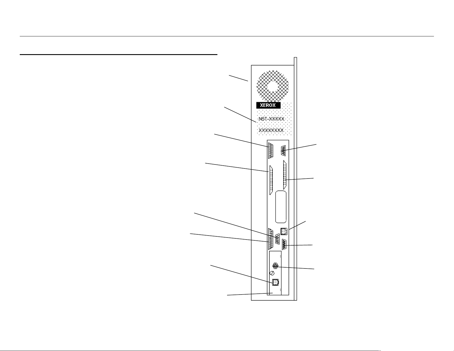
Controller Port Location
Floppy Disk Drive
N5T Product Code
User Interface Power
(7346/56 Scanner)
User Interface Data
(7346/56 Scanner)
Scanner SCSI
Host SCSI
(Not used in DDS
environment)
Parallel
VPI
Ethernet (RJ-45)
Network Interface Card
(Multi-protocol) (Optional)
10/100
Ethernet
Serial
Ethernet (BNC)
Page 21

Controller Port Location (continued)
)
N5T/CNG Product
Code
New EV4
Controller for
use with the
8825 Printer
(Note: This inverted
orientation of ports
denotes an N5T Tag 3
Controller.)
Multiprotocol Network
Interface Card (Legacy
card on N5T, CNG uses
optional adapter on
Parallel Port.
Parallel
10/100 Ethernet
Host SCSI
(not used in DDS
environment)
User Interface
Data (7346/56
Scanners)
Serial
Ethernet (RJ-45)
Ethernet (BNC)
VPI
Scanner SCSI
User Interface
Power (7346/56
Scanner)
10/100 Ethernet
Extra slot for adding
an optional PCI
Mezzanine Card, or
for installation of
7346/56 SCSI Kit.
Parallel
Serial
User Interface to
7346/56 scanners
using only the 15 pin
plug of 7346/56 cable
Serial Debug
8825/8830 Controller Setup Manual for Firmware 6.0 5
Page 22
8825/8830 Controller Setup Manual for Firmware 6.0 6
Controller Overview (continued)
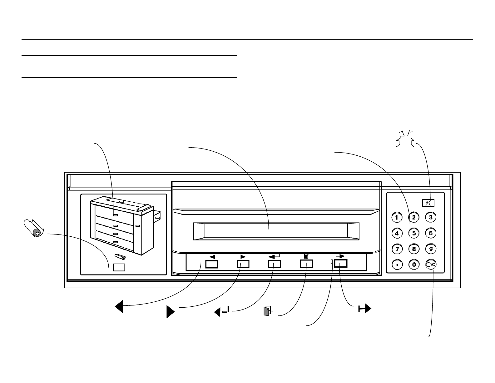
Printer Control Panel
The purpose of this page is to familiarize you with the location of the
8825/8830 printer Control Panel LEDs and buttons. Details on the LEDs and
buttons are available in the sections of this chapter entitled Graphic &
Message Displays and Control Panel buttons respectively.
Graphic Display
(8830 Printer shows 3
drawers; 8825 shows 2)
Media
Numeric Keypad
and Cancel Clear
button
Message Display
Language
Previous
Next
Enter
Exit
LED (On-line)
On-line/Off-line
Cancel/Clear Button
Page 23

Controller Overview (continued)
Learning the Displays
Graphic & Message Displays
The Graphic Display shows an outline of the printer and the Message Display
is a 2 x 40 character LCD window:
On-Line Indicator Light
There is one LED (Light Emitting Diode) on the 8825/8830 Printer’s Control
Panel.
The LED which is located below the Display Window is:
LED NAME
ON-LINE
* When the 8825/8830 Printer OFF-LINE mode is selected, the
Controller will continue to accept prints jobs until the SDRAM or hard disk is
full. The stored data files will be printed when the ON-LINE mode is selected.
If the ON-LINE button is pressed to select the OFF-LINE mode while
the 8825/8830 Printer is printing a job, the job will complete before switching
to the OFF-LINE mode. During the time the printer continues to print the job,
the ON-LINE LED will blink. When the OFF-LINE mode is allowed, the ONLINE LED will be off.
FUNCTION
ON-LINE LED is lit when the printer is set to
accept print jobs through local ports or across the
network. The ON-LINE LED is off when the
printer has been deselected and will not print
jobs*. Select or deselect the On-Line mode by
pressing the ON-LINE button on the Control
Panel.
DISPLAY
NAME
GRAPHIC
DISPLAY
MESSAGE
DISPLAY
STEADY ON FLASHING
Area of printer that is
affected by the fault. Out of
supplies in this area and will
not function.
All status, Printer and
Controller fault messages,
and the menus are
displayed here. All printer
faults are displayed first and
then any controller faults.
Low on supplies
in this area, but
will still function.
Indicates cursor
area of display
screen when
menus are
displayed.
8825/8830 Controller Setup Manual for Firmware 6.0 7
Page 24

8825/8830 Controller Setup Manual for Firmware 6.0 8
Controller Overview (continued)
Learning the Control Panel Buttons
ON-LINE
If the printer is On-line (operating), pressing this key will pause the
printer. Jobs will still be accepted from the various host interfaces
and spooled to DRAM or hard disk; however, print data will not be
sent to the print engine. When the printer is not paused, the
associated LED next to this button will be lit. Taking the printer Offline will not abort the currently printing page; it will print to
completion. During the interval between when the Off-line state
was requested and the currently printing job completes, the Offline LED will blink. Pressing this key when the printer is in any
setup menu will cause the printer to exit the menu and directly
return to On-line. Pressing this key when the printer is Off-line and
not in the menu will also cause the printer to return to On-line.
LANGUAGE
This key switches the display language from the primary
language to the secondary language. A second language option
must be installed in the printer for this function to operate.
EXIT
In menu mode, this EXIT key returns the user to the next higher
level in the menu tree. When in a menu, the ENTER key must be
pressed prior to pressing the EXIT key for the selected operation to
be performed. The EXIT key may therefore be used to “cancel” a
selected operation. At the top level of the menu, pressing the EXIT
key results in going to the printer paused display.
ENTER
In the menu mode, the ENTER key confirms the currently displayed
menu item. If this item is at the end of the menu tree and represents an
actual selection of a setting or parameter, then the selection is executed.
If this item is an intermediate or top-level node in the menu tree, the
selected “branch” of the menu tree is descended. When not in the
printer menu, you may enter the top level of the menu by pressing this
key after pressing the OFF-LINE key.
NEXT
In a menu mode, this key advances the LCD display to the next item in
whatever menu is currently being displayed. It operates in a “wraparound” fashion.
MEDIA
This key enables the user to specify the new media installed in the
printer. This is a print engine setup and does not change any
controller setup modes.
Page 25

Controller Overview (continued)
Learning the Control Panel Buttons (continued)
PREVIOUS
In a menu mode, this key moves the current menu selection to the
previous item in whatever menu is currently being displayed. It
operates in a “wrap-around” fashion.
Numeric Keypad and CANCEL/CLEAR button
In the setup defaults mode, the digits 0 through 9, and the decimal key, are
used to input numeric information.
In the setup defaults mode, the CLEAR key is used to clear the current
entered value prior to entering a new value. In other modes, the CLEAR key
is used to cancel the most mature job in the system, whether it is in a printing
or processing state. When the CLEAR button is pressed, you will be
prompted to confirm the Cancel operation.
8825/8830 Controller Setup Manual for Firmware 6.0 9
Page 26

8825/8830 Controller Setup Manual for Firmware 6.0 10
10. Fill in the requested name and addressing information and click
Controller Overview (continued)
Over The Wire Software License Feature Enabling
Beginning with the release of Firmware 4.0, optional software features can be
enabled by using the Document Submission Tool (part of AccXES Client
Tools) or the Web Printer Manager Tool* to send a “feature key” file to the
Controller over the network, serial, or parallel cable connection.
Typical Method for Enabling Software License Features
1. Order the feature from your authorized XES Reseller.
2. You will receive a kit with a diskette and a unique Coupon ID number.
3. Print a Printer Configuration Test Print from the 8825/8830 system and
identify the Advanced Network HW Address.
4. Using the Test Print, confirm that the firmware version in your printer is
4.0 or greater. If not, see the “Over The Wire Firmware Upgrading”
instructions in this Manual.
5. Using your Internet browser access www.xes.com/keys.
6. Select a language (English, French, German, Italian, Spanish, or
Portuguese).
“Continue.”
11. After submitting the information, verify that all information on the
Summary Page is correct and click on the “Download Feature Key (file)”
button. A “Save As” dialog box will appear. Save the file to your hard
drive or to the diskette that came in the kit.
12. Submit the file to the 8825 or 8830DDS system using the Document
Submission Tool (part of AccXES Client Tools), or using the "Upload File"
page of the Web Printer Manager Tool, accessed through a web browser
installed on your workstation.
13. AFTER WAITING 60 SECONDS, power off, then power on the Printer or
DDS System. Power OFF the Printer switch first, Controller
switch/breaker next, and scanner last. Power ON the Scanner first,
Controller switch/breaker next, and Printer switch last.
14. Print a Printer Configuration Test Print to confirm that the feature has
been enabled. If enabled, the word “PRESENT” will appear next to the
license name on the Test Print.
Three Software License Features Available With Firmware 6.0
Effective with the release of Firmware 6.0, the three Software License
Features that can be “over the wire” enabled are PostScript 3 with PDF
printing, Scan-to-Net* and Job Accounting.
* Note: A 10/100 Ethernet port/card is required Controller equipment for
supporting both the Web PMT and Scan-to-Net functionality.
7. Click on the radio button for “Redeem a Coupon for a Feature Key (file)”
and click “Continue.”
8. Enter the following information and click “Continue”
Coupon ID (obtained from certificate or disk label in the kit)
Feature (Scan-to-Net or Account Data Tracking)
Advanced Network HW Address (from Test Print)
Controller Serial Number (from tag on printer’s Controller)
9. Enter the Advanced Network HW Address a second time and click
“Confirm.”
Page 27

Controller Overview (continued)
Software License Feature Enabling (continued)
Effect of Purchased Hardware on the Need to Enable Software License
Features
The need to enable Software License Features depends upon purchased
equipment as stated below:
Scan-to-Net Licensed Feature
If this feature is desired, a Scan-to-Net license is required for all systems
using a 7346 scanner (such as the 8825 DDS). The license is not required
for systems using a 7356 scanner (such as the 8830 DDS) assuming a
firmware level of 2.5 or higher. W hen the feature is disabled, the “Ready to
Scan” display on the DDS Control Panel will read “Scan Mode Disabled.”
Job Accounting Licensed Feature
If this feature is desired, a Job Accounting license is required for all 8825
systems. The license is not required for 8830 systems assuming a firmware
level of 4.0 or higher. When the feature is disabled, Job Accounting PJL
(printer job language) commands will return an error message. Job
Accounting functions on the Printer Control Panel will be unavailable. Job
Accounting functions on the DDS Control Panel will be unavailable.
PostScript 3 with PDF Printing
If this feature is desired, a license is required for all 8825/8830 systems.
8825/8830 Controller Setup Manual for Firmware 6.0 11
Page 28

8825/8830 Controller Setup Manual for Firmware 6.0 12
Controller Overview (continued)
Over The Wire Firmware Upgrading
Coinciding with the release of Firmware 4.0 and the availability of the new
Web Printer Manager Tool, it is now possible to upgrade Firmware versions
with new releases by sending a file to the Controller over the network, serial,
or parallel cable connection.
Customers can obtain new Firmware releases from the internet or in the form
of a CD ROM upgrade. If obtaining the Firmware from the internet, go to
www.xes.com and follow the instructions provided.
Use the Document Submission Tool (part of AccXES Client Tools) or the
Web Printer Manager Tool to send the downloaded Firmware upgrade to the
Controller. Note that the Web PMT includes a handy Upload button on the
"Upload File" page to assist in sending the new Firmware upgrade to the
Controller.
Note: For upgrading existing Firmware version 2.7 (or newer) to a new
release, existing parameter settings will not be reset to factory defaults.
Parameters that are new in the upgraded release will simply be assigned
new factory defaults. For upgrading existing Firmware 2.5 or older, print
out a full set of Test Prints (from the Printer Control Panel’s “Utilities”
menu) BEFORE performing the upgrade as all settings will be returned to
their Factory Defaults and you will lose your custom settings for the
Active Parameters set. For Active Parameters Set information, see
“Setting the Active Parameters Option” in this manual.
Page 29

Controller Overview (continued)
Controller Specifications(EV4 Controller for 8825)
Physical Characteristics
The Controller is attached to the side panel of the 8825 Printer as an
embedded device.
Electrical Requirements
100 - 250 VAC auto-ranging power supply.
Agency Approvals
Safety: UL 1950, CA22.2 No. 950 (CUL), EN 60950 (CE Mark)
EMC: CE Mark, FCC Class A, Canada Radio Interference Regulations
Class A, VCCI Class 1
Hardware Specifications
CPU Power PC 8240 (603e) operating at 250 MHz clock speed.
RAM 64MB DRAM is standard. Maximum RAM is 256MB. Two DIMM
Slots accommodate 64 or 128MB, PC100, DIMMs.
Hard disk Ultra SCSI, 7200 rpm internal hard disk drive.
8825/8830 Controller Setup Manual for Firmware 6.0 13
Page 30

8825/8830 Controller Setup Manual for Firmware 6.0 14
Controller Overview
Controller Specifications (EV4 for 8825) (continued)
I/O Ports
Serial Two 9 pin Host serial ports provided. One is used by the 8825
DDS scanner (7346 or 7356) when this option is connected. The
second is used as an input port for receiving data via serial port
connection.
Parallel (IEEE 1284 Compliant) High density port connector provided.
SCSI Optional 50 pin SCSI-2 card available.
VPI Optional card available.
TCP/IP 10/100 Ethernet Network Interface Port provided: RJ-45
connection, supporting TCP/IP only.
Network Optional External Ethernet Adapter available to support TCP/IP,
Novell 3.x, 4.x, 5.x, and NetBEUI.
Page 31

Controller Overview
Controller Specifications (N5T/CNG Product Code)
Physical Characteristics
The Controller is attached to the side panel of the 8830 Printer as an
embedded device.
Electrical Requirements
100 - 250 VAC auto-ranging power supply.
Agency Approvals
Safety: UL 1950, CA22.2 No. 950 (CUL), EN 60950 (CE Mark)
EMC: CE Mark, FCC Class A, Canada Radio Interference Regulations
Class A, VCCI Class 1
Hardware Specifications
Note: The hard drive is required for installation of 6.0 firmware.
CPU Power PC 740 operating at 200 MHz clock speed.
ROM/RAM For both Standalone Printer and Printer with Scanner
Configurations
• Non-PostScript - 4MB Flash ROM (N5T only) and 64MB
SDRAM DIMM
• PostScript - 8MB Flash ROM (N5T only) and 64MB SDRAM
DIMM
• Maximum RAM is 192MB
Floppy 1.44 Mbytes (standard 3.5 inch)
Hard disk Ultra SCSI, 7200 rpm internal hard disk drive (optional on N5T,
standard on CNG)
8825/8830 Controller Setup Manual for Firmware 6.0 15
Page 32

8825/8830 Controller Setup Manual for Firmware 6.0 16
Controller Overview
Controller Specifications (N5T/CNG Product Code)
(continued)
I/O Ports
Serial Two 9 pin Host serial ports provided. One is used by the
8825/8830 DDS scanner when this option is connected. The
second is used as an input port for receiving data via serial port
connection.
Note: For firmware releases 2.0, the upper serial port is used for
data input; the lower serial port is used for service.
For later releases, the upper serial port is used for connection to
the 8825/8830 DDS Control Panel if a scanner is detected during
startup. If a scanner is not detected during startup, the upper
serial port becomes the service port.
The lower serial port is used for data input.
Parallel (IEEE 1284 Compliant) High density port connector provided.
SCSI 50 pin Ultra SCSI Connector provided.
VPI 37 pin D Connector provided.
Scanner 50 pin Ultra SCSI Connector provided.
Ethernet Built-in 10/100 Ethernet Network Interface: RJ-45 connection,
supporting TCP/IP only.
Option N5T has a legacy 3003-XTP Network Interface Card: RJ-45 and
Coax connections, with multiprotocol support, 10 Mb/s Ethernet
only. This card is now replaced by the optional External Ethernet
Adapter connected to the parallel port.
Important Note: For the location of the ports with the new N5T with Tag 3
Controller, see the illustration in the Controller Overview section of this
manual.
Page 33

Controller Overview (continued)
• PostScript PPD System Print Driver
• AccXES Client Tools
• Web PMT (requires Firmware Release 4.0 or higher)
Job Printing/Processing Specifications
Network Protocols
Legacy 3003-XTP NIC (replaced by External Ethernet Adapter)
TCP/IP (lpr/lpd, telnet, TFTP puts,...)
EtherTalk
Novell IPX/SPX PServer for Ver. 3.x and 4.x w/NDS
NetBEUI
DLC/LLC
10/100 Ethernet Card/Port
TCP/IP only
External Ethernet Adapter (optional on all Controllers)
TCP/IP, Novell 3.x, 4.x, 5.x, and NetBEUI
Platforms supported
SUN OS and Solaris
Windows 95/98/NT 4.0/2000
Auto Port Sensing
Windows NT 4.0 & 2000 platforms:
• HP-GL/2/RTL Print Driver
• ADI Driver for AutoCAD R13/14
• HDI Driver for AutoCAD 2000 and 2000i
• PostScript PPD System Print Driver
• AccXES Client Tools
• Web PMT (requires Firmware 4.0 or higher)
Yes. Ports may also be enabled or disabled remotely.
Client Software
Windows 95/98 platforms:
• HP-GL/2/RTL Print Driver
• ADI Driver for AutoCAD R13/14
• HDI Driver for AutoCAD 2000 and 2000i
8825/8830 Controller Setup Manual for Firmware 6.0 17
Page 34

8825/8830 Controller Setup Manual for Firmware 6.0 18
Job Queue Management
Controller Overview
Job Printing/Processing Specifications (continued)
Single prioritized queue, adjustable priority, job canceling, queue
monitoring provided.
UNIX platform:
• tftp puts and ftp
• telnet
• lpr/lpd support
• AccXES Client Tools (Solaris)
• Web PMT (requires Firmware Release 4.0 or higher)
Job Control Language
HP-PJL with custom extensions.
Job Spooling/Queue
Internal to EV4 and N5T Controllers. Additional job input buffer with the
hard disk.
Data Formats
HP-GL, HP-GL2, HP-RTL, CalComp 906 /907 /951 /PCI, TIFF 6.0,
NIRS, Cals 1 & 2, Versatec Raster, XES 150 emulation, CGM, C4,
Filenet, VDS (Ordered Vector, Blocked Raster, Compacted Raster,
Versatec Random Format), VCGL, Optional Adobe PostScript 3 with
PDF
Compression types (for applicable raster formats):
Long plot
Up to 80 feet (24.38 Meters) printing.
Up to 100 feet (30.48 Meters) copying.
Auto format recognition
Yes
Color Support
All supported data formats which are color capable (TIFF, HP-RTL,
HPGL/GL2, CGM, CalComp, NIRS, VCGL) will be processed and
converted to grayscale using a proprietary half-toning algorithm
supporting 128 gray levels.
Color input in PostScript is converted to grayscale using the same
halftoning matrix with 128 gray levels.
CCITT G4, G3-ID, G3-2D, Packbits, RLE, Seed Row, Adaptive.
Compression
Hardware lossless Starlite 3410 chip provided.
Page 35

Controller Overview
Job Printing/Processing Specifications (continued)
Electronic Collation
200 E size pages with 64MB RAM and a 9.1GB hard drive.
Folding and Stacking
Extended Processing Options
• Autoscaling
• Autorotation
• Auto Size Detect
• Banner Sheets
• Rotation (0, 90, 180, 270)
• Scaling (10% to 999%)
• Justification
• Margins
• Raster Stamps
• Labeling
• Page Composition/Plot Overlay
• Mirror
• Vector Halftone
• Media Mismatch Management
• Plot Nesting
Optional Online Folder is available. Optional Stacker is available with a
capacity of 1000 prints.
Palettes and Patterns
8 user-defined pen palettes, and 1 read-only factory default palette.
User defines pen color, width, and pattern for up to 256 pens. 64
patterns (33 shading patterns, 16 random patterns, 15 user defined
patterns). Each pen attribute is individually controllable.
• Control Panel Lockout
• Scan-to-Net (8825 DDS optional)
• Job Accounting (8825 & 8825 DDS optional)
Number of copies
1 to 999
8825/8830 Controller Setup Manual for Firmware 6.0 19
Page 36

8825/8830 Controller Setup Manual for Firmware 6.0 20
Controller Overview (continued)
Preparing The Serial Ports
The Host Serial Port
This port requires a null modem serial cable to be connected from the
Controller host serial port to the workstation serial port. It is necessary to
use the appropriate software drivers or system commands to send jobs to
the Controller.
The Controller serial host interface port supports user-definable Baud Rate,
Flow Control, and Parity.
Enable Controller Serial Port
Use the Setup I/O Ports menu of the Printer Control Panel to enable the
Serial port and select the Baud Rate, Flow Control, and Parity to match those
set at the workstation.
Network Protocols Supported
Does not apply to the serial port.
• HDI Driver for AutoCAD 2000 and 2000i
• PostScript PPD System Print Driver
• Document Submission Tool (part of AccXES Client Tools)
UNIX PLATFORM:
Does not apply to the serial port.
Software Supported
WINDOWS 95/98 PLATFORM:
• HP-GL/2/RTL Print Driver
• ADI Driver for AutoCAD R13/14
• HDI Driver for AutoCAD 2000 and 2000i
• PostScript PPD System Print Driver
• Document Submission Tool (part of AccXES Client Tools)
WINDOWS NT 4.0 & 2000 PLATFORMS:
• HP-GL/2/RTL Print Driver
• ADI Driver for AutoCAD R13/14
Page 37

Controller Overview (continued)
Preparing The Serial Ports (continued)
Data Formats Supported
• HP-GL, HP-GL/2
• HP-RTL
• TIFF, NIRS
• CALS 1 & 2
• CalComp 906/907/951/PCI with Electrostatic extensions
• VDS (Versatec Data Standards)
• VCGL
• CGM
• C4
• Filenet
• Versatec Raw Raster
• Optional PostScript 3 with PDF
8825/8830 Controller Setup Manual for Firmware 6.0 21
Page 38

8825/8830 Controller Setup Manual for Firmware 6.0 22
Controller Overview (continued)
Preparing The Serial Ports (continued)
Serial Cable Description
The serial cable should be wired as a null modem with a standard 9 pin D
connector at the controller end and a connector to match the workstation
serial port connector at the host end.
RS-232 Connector Pin Out
Pin Number Signal Name
1 HOST_DCD*
2HOST_SIN
3HOST_SOUT
4HOST_DTR*
5 GROUND
6HOST_DSR
7HOST_RTS*
8HOST_CTS*
9 No Connect.
Null Modem Cable Pin Out
9 Pin 9 Pin
1 DCD 7 RTS
2 RD 3 TD
3 TD 2 RD
4 DTR 6 DSR
5 GRD 5 GRD
6 DSR 4 DTR
7 RTS
8 CTS
99
8 CTS
1 DCD
Page 39

Controller Overview (continued)
Preparing The Parallel Port
Parallel Port
This port requires connecting a parallel cable between your workstation's
parallel port and the Controller parallel port. An appropriate software print
driver or system command is necessary to direct jobs to the printer. Enabling
the parallel port is done from the W eb Printer Manager Tool or from the
8825/8830 Control Panel.
DATA FORMATS SUPPORTED
• HP-GL, HP-GL/2
• HP-RTL
• TIFF, NIRS
• CALS 1 & 2
• CalComp 906/907/951 PCI with Electrostatic extensions
• CGM
• VDS (Versatec Data Standards)
• VCGL
• C4
• Filenet
• Optional PostScript 3 with PDF
Enable Controller Parallel Port
Use the Setup I/O Ports menu of the Printer Control Panel to enable the
Parallel port.
Network Protocols Supported
Does not apply to the parallel port.
Software Supported:
WINDOWS 95/98 PLATFORM:
• HP-GL/2/RTL Print Driver
• ADI Drivers for AutoCAD R13/14
• HDI Driver for AutoCAD 2000 and 2000i
• PostScript PPD System Print Driver
• Document Submission Tool (part of AccXES Client Tools)
WINDOWS NT 4.0 & 2000 PLATFORMS:
• HP-GL/2/RTL Print Driver
• ADI Driver for AutoCAD R13/14
• HDI Driver for AutoCAD 2000 and 2000i
• PostScript PPD System Print Driver
• Document Submission Tool (part of AccXES Client Tools)
Parallel Cable Description
The cable connector is a standard, “mini-Centronics” P1284C connector.
A 10 foot, high density P1284A to P1284C cable is available from Xerox (Part
# 98S03302).
The maximum length of the parallel cable must not exceed 12 feet (3.66 m).
8825/8830 Controller Setup Manual for Firmware 6.0 23
Page 40

8825/8830 Controller Setup Manual for Firmware 6.0 24
Preparing The Parallel Port (continued)
P1284C Parallel Connector Pin Out
Pin
Number
1 PERBSYA 19 GROUND
2 XFLAGA 20 GROUND
3 PERCLKA 21 GROUND
4 DATAVA* 22 GROUND
5 AKDARQA 23 GROUND
6 PPORTA0 24 GROUND
7 PPORTA1 25 GROUND
8 PPORTA2 26 GROUND
9 PPORTA3 27 GROUND
10 PPORTA4 28 GROUND
11 PPORTA5 29 GROUND
12 PPORTA6 30 GROUND
13 PPORTA7 31 GROUND
14 INITA* 32 GROUND
15 HSTCLKA 33 GROUND
16 A1284A 34 GROUND
17 HSTBSYA 35 GROUND
18 No Connect 36 PRINTOK
Signal Name Pin
Number
Signal Name
Page 41

Controller Overview (continued)
Preparing The VPI Port
VPI Port
To use the VPI port requires a workstation with a VPI interface card and
appropriate software. An optional card is also required for use with the 8825
EV4 Controller.
Enable Controller VPI Port
Use the Setup I/O Ports menu of the Printer Control Panel to enable the VPI
port.
Network Protocols Supported
Does not apply to the VPI port.
Software Supported
• ServeWare
• VGS (in Xerox 150 Emulation Mode)
Data Formats Supported
• Xerox 150 Emulation
• Versatec Raw Raster
• VDS
• VCGL
VPI Connector Pin Out
Connector
Pin Number
1 IN01+ 20 IN01-
2 IN02+ 21 IN02-
3 IN03+ 22 IN03-
4 IN04+ 23 IN04-
5 IN05+ 24 IN05-
6 IN06+ 25 IN06-
7 IN07+ 26 IN07-
8 IN08+ 27 IN08-
9 RCLEAR- 28 RCLEAR+
10 PICLK+ 29 PICLK-
11 READY- 30 READY+
12 PRINT+ 31 PRINT-
13 No Connect 32 INOP-
14 RSPP- 33 RSPP+
15 RESET- 34 RESET+
16 RFFED- 35 RFFED+
17 REOT- 36 REOT+
18 RLTER- 37 RLTER+
19 INOP+
Signal Name Connector
Pin Number
Signal Name
VPI Cable Description
The maximum length of a VPI cable must not exceed 1000 feet (304.8 m).
8825/8830 Controller Setup Manual for Firmware 6.0 25
Page 42

8825/8830 Controller Setup Manual for Firmware 6.0 26
Controller Overview (continued)
Preparing the Host Ultra SCSI Port
Ultra SCSI Port (Host)
To use this port your workstation must have a SCSI interface card and
appropriate software installed and operating. An optional card is also
required for use with the 8825 EV4 Controller.
Enable Controller SCSI Port
Use the Setup I/O Ports menu of the Printer Control Panel to enable the port
and set a device number compatible with your workstation. By default, the
host SCSI port bus termination is enabled.
Network Protocols Supported
Does not apply to the SCSI-2 port.
Software Supported
• ServeWare Version 2.42 or later.
• VGS (in Xerox 150 Emulation Mode)
Data Formats Supported
• Xerox 150 Emulation
• Versatec Raw Raster
• VDS
• VCGL
Ultra SCSI Connector Pin Outs (host)
Pin
Numbe
r
1 GROUND 18 GROUND 35 GROUND
2 GROUND 19 GROUND 36 GROUND
3 GROUND 20 GROUND 37 No Connect
4 GROUND 21 GROUND 38 SATRMPW
5 GROUND 22 GROUND 39 No Connect
6 GROUND 23 GROUND 40 GROUND
7 GROUND 24 GROUND 41 SAATN*
8 GROUND 25 GROUND 42 GROUND
9 GROUND 26 SADB0* 43 SABSY*
10 GROUND 27 SADB1* 44 SAACK*
11 GROUND 28 SADB2* 45 SARST*
12 No Connect 29 SADB3* 46 SAMSG*
13 No Connect 30 SADB4* 47 SASEL*
14 No Connect 31 SADB5* 48 SACD*
15 GROUND 32 SADB6* 49 SAREQ*
16 GROUND 33 SADB7* 50 SAIO*
17 GROUND 34 SADBP*
Signal
Name
Pin
Numbe
r
Signal
Name
Pin
Numbe
r
Signal
Name
R
SCSI Cable Description
The SCSI-2 cable must not exceed a maximum length of 9.75 feet (3
meters).
Page 43

Controller Overview (continued)
Dynamic Host Configuration via:
− DHCP
Preparing The 3003-XTP NIC Ethernet Port
Ethernet Port (Legacy NIC for N5T Controller)
The optional, 3003-XTP Network Interface Card (NIC) provides connectivity
to two standard Ethernet type networks. 10Base2 (BNC Thinnet) and
10BaseT (Twisted Pair RJ-45) connectors are both available and the NIC
auto-senses the active connector.
To print using this port your workstation must have a Network Interface card
installed, protocols enabled, and appropriate software running. For complete
setup details see the 8825/8830/8855 Network Administrator’s Guide
available on the Internet at www.xes.com.
Note: All Controllers now use an optional, external Ethernet adapter
attached to the Controller's parallel port, to support TCP/IP, IPX/SPX, and
NetBEUI protocols. Contact your XES sales or service representative for
specific ordering and setup information.
Enabling the Controller Ethernet Port
Use the Setup I/O Ports menu of the Printer Control Panel to set the Ethernet
“Port Enable” to PRINTER, and set a protocol compatible with your network.
− RARP/BOOTP
Novell NetWare (IPX/SPX)
Auto sensing of frame types:
• Ethernet 2, Ethernet SNAP, 802.2, and 802.3
• Bindery mode
• NDS mode
EtherTalk
Phase I and Phase II
NetBEUI
Native MS NetBEUI
Refer to your Network Administrator or the 8825/8830/8855 Network
Administrator's Guide (available at www.xes.com) for additional information.
NETWORK PROTOCOLS SUPPORTED
TCP/IP
• lpr/lpd
• TFTP
• Telnet
8825/8830 Controller Setup Manual for Firmware 6.0 27
Page 44

8825/8830 Controller Setup Manual for Firmware 6.0 28
WINDOWS NT 4.0 & 2000 PLATFORMS:
Controller Overview
Preparing The 3003-XTP NIC Ethernet Port (continued)
• HP-GL/2/RTL Print Driver
• ADI Driver for AutoCAD R13/14
• HDI Driver for AutoCAD 2000 and 2000i
Software Supported:
WINDOWS 95/98 PLATFORM:
• HP-GL/2/RTL Print Driver
• ADI Driver for AutoCAD R13/14
• HDI Driver for AutoCAD 2000 and 2000i
• PostScript PPD System Print Driver
• Web Printer Manager Tool (Administration and Job Queue Management)
• AccXES Client Tools
• PostScript PPD System Print Driver
• Web Printer Manager Tool (Administration and Job Queue Management)
• AccXES Client Tools
UNIX PLATFORM:
• tftp puts
• telnet
• lpr/lpd support
• AccXES Client Tools (Solaris)
• Web PMT (requires firmware 4.0 release, or higher)
Page 45

Controller Overview
Preparing The 3003-XTP NIC Ethernet Port (continued)
Data Formats Supported
• HP-GL, HP-GL2
• HP-RTL
• CalComp 906 /907 /951 /PCI
• TIFF 6.0
• NIRS
• Cals 1 & 2
• CGM
• VDS (Versatec Data Standards)
• VCGL
• C4
• Filenet
RJ-45 Connector Pin Assignments
Pin
Number
1 TX+ 5 No Connection
2TX- 6RX-
3 RX+ 7 No Connection
4 No Connection 8 No Connection
Signal Name Pin
Number
Signal Name
• Optional PostScript 3 with PDF
Ethernet Cable Description
Thinnet (10base2) Coaxial Cable with BNC connectors (plugged into a “T”
connector at each Network Interface).
10BaseT (Twisted Pair) Category 5 cable with RJ-45 connectors.
8825/8830 Controller Setup Manual for Firmware 6.0 29
Page 46

8825/8830 Controller Setup Manual for Firmware 6.0 30
• Web PMT (requires Firmware 4.0 release or higher)
Controller Overview (continued)
Preparing The 10/100 Ethernet Port
Overview
This port is standard on the all Controllers.
To print using this port your workstation must have a Network Interface Card
installed, protocols enabled, and appropriate software running.
Enable Controller Ethernet Port
Use the Setup I/O Ports menu of the Printer Control Panel to set the Ethernet
“Port Enable” to “ADVANCED.”
Refer to your Network Administrator or the 8825/8830/8855 Network
Administrator's Guide (available at www.xes.com) for additional information.
Network Protocols Supported:
TCP/IP
• lpr/lpd
WINDOWS 4.0 & 2000 PLATFORMS:
• HP-GL/2/RTL Print Driver
• ADI Driver for AutoCAD R13/14
• HDI Driver for AutoCAD 2000 and 2000i
• PostScript PPD System Print Driver
• AccXES Client Tools
• Web PMT (requires Firmware 4.0 release or higher)
UNIX PLATFORM:
• Web PMT (requires Firmware 4.0 release or higher)
• tftp puts and ftp
• lpr/lpd support
• AccXES Client Tools (Solaris)
• tftp and ftp
Software Supported:
WINDOWS 95/98 PLATFORM:
• HP-GL/2/RTL Print Driver
• ADI Driver for AutoCAD R13/14
• HDI Driver for AutoCAD 2000 and 2000i
• PostScript PPD System Print Driver
• Web Printer Manager Tool (Administration and Job Queue Management)
• AccXES Client Tools
Page 47

Controller Overview
Preparing The 10/100 Ethernet Port (continued)
Data Formats Supported
RJ-45 Connector Pin Assignments
• HP-GL, HP-GL2
• HP-RTL
• CalComp 906 /907 /951 /PCI
• TIFF 6.0
• NIRS
• Cals 1 & 2
• CGM
• VDS (Versatec Data Standards)
• VCGL
• C4
• Filenet
• Optional PostScript 3 with PDF
Ethernet Cable Description
10Base-T (Twisted Pair) Category 5 cable with RJ-45 connectors.
Pin
Number
1 TX+ 5 No Connection
2TX- 6RX-
3 RX+ 7 No Connection
4 No Connection 8 No Connection
Signal Name Pin
Number
Signal Name
8825/8830 Controller Setup Manual for Firmware 6.0 31
Page 48

8825/8830 Controller Setup Manual for Firmware 6.0 32
Controller Overview (continued)
Menu Tree Access Instructions and Overview
Access Instructions
The Controller has three operating conditions as indicated in the display
window of the Printer Control Panel. These conditions are: PAUSED, IDLE,
and PROCESSING. All the printer setup menus must be accessed in the
PAUSED mode. To gain access to the PAUSED mode, when the display
window of the Printer Control Panel shows IDLE, press the “ON-LINE” key to
take the printer off line.
In the PAUSED condition, press the “ENTER” key to display the UTILITIES
menu. UTILITIES represents the first of six Top Level menus available for
your printer configuration use. If you press the “NEXT” key, the additional 5
Top Level menus will be displayed every time you press the key.
The six Top Level menus are further divided into sub-menus including all
printer default settings and user-selectable operating parameters. These
sub-menus are accessed by pressing the “ENTER” key when one of the six
Top Level menus is displayed in the window of the Printer Control Panel.
The diagram below, and the “Menu Function Locator” information that
immediately follows, provides a quick reference to all of the operating
parameters that can be accessed from the six Top Level menus using the
Printer Control Panel.
Page 49

Menu Tree Overview
UTILITIES SETUP I/O PORTS SETUP PRINTER PROCESSING DEFAULTS SYSTEM ADMINISTRATION PRINTER MENU
TEST PRINT SCSI BANNER PAGE ELECTRONIC COLLATION JOB ACCOUNTING AUDIBLE INDICATORS*
SYSTEM
INFORMATION
POSTSCRIPT
PARTITION
JOB QUEUE IPX/SPX (for legacy
ETHERTALK (for legacy
3003-XTP NIC)
NETBEUI (for legacy
3003-XTP NIC)
3003-XTP NIC)
ETHERNET TCP/IP IMAGE SCALE MODE FINISHER OPTIONS SET FACTORY DEFAULTS DIAGNOSTICS*
SERIAL VECTOR HALFTONE FINISHING LONG PLOT BILLING METERS*
PARALLEL SET DATE AND TIME JUSTIFICATION X
VPI TIMEOUT JUSTIFICATION Y * Refer to Printer Operator
DIAGNOSTICS PAGE NUMBER OF COPIES CHANGE PASSWORD TIMERS**
TONER DENSITY EMULATION MENU LOCKOUT PRINTER ADJUSTMENTS*
ERROR PAGE JOB PRIORITY CONTROLLER CONFIGURATION FINISHER SETTINGS**
Manual
MAXIMUM PLOT LENGTH MARGIN TOP ** Covered in this User
EMULATIONS MARGIN BOTTOM
BOND MISMATCH MODE MARGIN LEFT
FILM MISMATCH MODE MARGIN RIGHT
VELLUM MISMATCH MODE OVERSIZE MARGIN
MISMATCH QUEUEING ENABLE
PEN PALETTE PAPER SIZE DETECT
ACTIVE PARAMETER SET MEDIA SOURCE
PLOT NESTING MEDIA TYPE
UNDERSIZE MARGIN
MIRROR IMAGE
PAGE ROTATE
PAGE SCALING
MEDIA SIZE
RASTER STAMP
LABEL
Guide
8825/8830 Controller Setup Manual for Firmware 6.0 33
Page 50

8825/8830 Controller Setup Manual for Firmware 6.0 34
POSTSCRIPT PARTITION
Accessing the Default Setup
NORMAL
Menus
Quick Menu Locator
The Controller status is one of three conditions as indicated by the display
panel. The conditions are: PAUSED, IDLE, and PROCESSING. All the
controller default setup menus must be accessed in the PAUSED mode.
Getting to the 6 Controller Setup Menus
Press the ON-LINE key, then the ENTER key. This displays the UTILITIES
menu. Press the NEXT key to step to a different menu. Press the ENTER
key when the desired menu is displayed to access the menu items. When in
the desired menu press the NEXT key to access the desired function.
Quick Menu Item Locator
UTILITIES MENU
TEST PRINT
OPTIMIZED
NONE
JOB QUEUE
MISMATCH QUEUE
Notes:
The TEST PRINT set (ALL) consists of one sheet of PRINTER
CONFIGURATIONS, one sheet of PRINTER SETTINGS, 8 sheets of
PEN PALETTES, and one sheet of PostScript firmware information (if this
firmware is installed).
The TEST PRINT(s) will not be processed by the printer until the ONLINE mode is entered. The TEST PRINTS will be printed on ‘A’ size
paper when ‘ANY’ is the media default, otherwise the selected default
paper size is used.
Note: When the POSTSCRIPT PARTITION parameter is changed, the
controller will automatically reboot to re-partition the hard drive.
ALL
PRINTER CONFIGURATION
PRINTER SETTINGS
PEN PALETTES
POSTSCRIPT (displayed when PostScript option is installed)
SYSTEM INFORMATION
JOB ACCOUNTING
DISPLAY REPORTS
Page 51

Accessing the Default Setup Menus (continued)
Quick Menu Item Locator
SETUP I/O PORTS MENU
SCSI
PORT ENABLE
TARGET ID
BUS TERMINATION ENABLE
ETHERTALK (for legacy 3003-XTP NIC)
PORT ENABLE
PHASE
NETBEUI (for legacy 3003-XTP NIC)
PORT ENABLE
IPX/SPX (for legacy 3003-XTP NIC)
PORT ENABLE
FRAME
NDS ENABLE
ETHERNET TCP/IP
PORT ENABLE
OFF
PRINTER
ADVANCED
TCP/IP ADDRESS
TCP/IP GATEWAY
TCP/IP MASK
DHCP ENABLE
RARP/BOOTP ENABLE
SERIAL
PORT ENABLE
BAUD RATE
300 - 19,200
FLOW CONTROL
NONE, XON/XOFF, RTS/CTS, BOTH (XON/XOFF & RTS/CTS).
PARITY
NONE, EVEN, or ODD
PARALLEL
PORT ENABLE
VPI
PORT ENABLE
TIME OUT ENABLE
8825/8830 Controller Setup Manual for Firmware 6.0 35
Page 52

8825/8830 Controller Setup Manual for Firmware 6.0 36
Accessing the Default Setup Menus (continued)
Quick Menu Item Locator
SETUP PRINTER MENU
BANNER PAGE
ENABLE
POSITION
DIAGNOSTICS PAGE
ENABLE
TONER DENSITY
INPUT NUMBER ( 0 - 10 )
ERROR PAGE
LEVEL 1
LINE OPTIMIZED
SET DATE AND TIME
MONTH, DAY, YEAR, HOUR, MINUTE, SECONDS
TIMEOUT
INPUT SECONDS ( 5 - 300 )
MAXIMUM PLOT LENGTH
INPUT CM ( 122 - 2438 cm )
LEVEL 2
NONE
IMAGE SCALE MODE
PHOTO
LINE
VECTOR HALFTONE
AREA OPTIMIZED
Page 53

Accessing the Default Setup Menus
RESOLUTION ( 50 - 4064 dpi )
Quick Menu Item Locator
SETUP PRINTER MENU (continued)
EMULATIONS
HPGL
MODE ( HPGL2 or HPGL758X )
EOP DETECTION
PG COMMAND
RP COMMAND
PLOTTER OFF COMMAND
FR COMMAND
AF COMMAND
AH COMMAND
NR COMMAND
SP/SP0 COMMAND
HPGL PALETTE ( INPUT NUMBER OF PALETTE )
HPGL PALETTE SOURCE ( JOB or PRINTER )
EOP DETECTION
SEARCH ADDRESS ( 999, 9999, BOTH, or NONE )
EOP COMMAND ( 1, 2, or NONE )
PAUSE COMMAND
NEW PLOT COMMAND
MANUAL COMMAND
TOP OF FORM COMMAND
START PLOT COMMAND
FORCE PLOT COMMAND
CALCOMP PALETTE ( INPUT NUMBER OF PALETTE )
CALCOMP PALETTE SOURCE ( JOB or PRINTER )
MERGE CONTROL DEFAULT (OFF or ON)
REINITIALIZE AFTER EOF (OFF or ON)
CALCOMP
CHECKSUM
EOM ( 0 - 31 )
NUM SYNCH ( 1 or 2 )
SYNCH CHARACTER ( 0 - 127 )
8825/8830 Controller Setup Manual for Firmware 6.0 37
Page 54

8825/8830 Controller Setup Manual for Firmware 6.0 38
Accessing the Default Setup Menus
Quick Menu Item Locator
SETUP PRINTER MENU (continued)
CGM
DEFAULT PAPER SIZE
CGM PALETTE ( INPUT NUMBER OF PALETTE )
CGM PALETTE SOURCE ( JOB or PRINTER )
BACKGROUND (FILE CONTROL or FORCE BLACK ON
WHITE )
POSTSCRIPT
DEFAULT PAPER SIZE
VERSATEC
RAW RASTER EMULATION ( MAKE SELECTION )
CHARACTER SET ( ASCII or EBCIDIC )
VCGL PALETTE SOURCE (JOB or PRINTER)
COLOR (FILE CONTROL or FORCE BLACK ON WHITE)
DEVICE RESOLUTION (400, 100, 200, 300)
BOND MISMATCH MODE
SCALING
QUERY
SUBSTITUTE
FILM MISMATCH MODE
SCALING
QUERY
SUBSTITUTE
VDS
CHARACTER SET ( ASCII or EBCIDIC )
VDS PALETTE ( INPUT NUMBER OF PALETTE )
VDS PALETTE SOURCE ( JOB or PRINTER )
TIFF
1 BIT PHOTO ( FILE CONTROL or IGNORE MIN = BLACK)
VCGL
VCGL PALETTE (0 - 8)
Page 55

Accessing the Default Setup Menus
Quick Menu Item Locator
SETUP PRINTER MENU (continued)
VELLUM MISMATCH MODE
SCALING
QUERY
SUBSTITUTE
MISMATCH QUEUEING ENABLE
(ON or OFF)
PEN PALETTE
INPUT NUMBER ( 0 - 8 )
COLOR NUMBER ( 0 - 150 )
PEN PATTERN ( 0 - 49 )
ACTIVE PARAMETER SET
INPUT NUMBER ( 0 - 9 )
PLOT NESTING
MODE ENABLE (ON or OFF)
EXCLUSIVE ENABLE (ON or OFF)
TIMEOUT
MARGIN
MAXIMUM LENGTH
8825/8830 Controller Setup Manual for Firmware 6.0 39
Page 56

8825/8830 Controller Setup Manual for Firmware 6.0 40
Accessing the Default Setup Menus
Quick Menu Item Locator
PROCESSING DEFAULTS MENU
ELECTRONIC COLLATION ( ON or OFF )
NUMBER OF COPIES ( 1 - 999 )
EMULATION
AUTO, CALCOMP, CALS1, CALS2, CGM, HPGL, TIFF6, VDS, C4,
FILENET, POSTSCRIPT, VRASTER
JOB PRIORITY
INPUT VALUE ( 1 - 10 )
FINISHER OPTIONS
NO FOLD, 190MM, 190+20MM, 210MM, 8.5X11, 7.5X11, 7.5X11+1 IN,
9X12 IN
JUSTIFICATION Y
BOTTOM
NUMERIC ( 0 - 2540 mm )
TOP
CENTER
MARGIN TOP
INPUT MM ( 0 - 2540 mm)
FINISHING LONG PLOT
0 (BYPASS) NO FOLD or Z FOLD
JUSTIFICATION X
LEFT
CENTER
RIGHT
NUMERIC ( 0 - 2540 mm )
Page 57

Accessing the Default Setup Menus
ROLL 2
Quick Menu Item Locator
PROCESSING DEFAULTS MENU (continued)
MARGIN BOTTOM
INPUT MM ( 0 - 2540 mm)
MARGIN LEFT
INPUT MM ( 0 - 2540 mm)
MARGIN RIGHT
INPUT MM ( 0 - 2540 mm)
OVER SIZE MARGIN
INPUT % ( 0 - 100 % )
UNDER SIZE MARGIN
INPUT % ( 0 - 100 % )
ROLL 3
MANUAL FEED
MEDIA TYPE
BOND
FILM
VELLUM
ANY
MIRROR IMAGE
OFF
MIRROR X
MIRROR Y
MIRROR XY
PAPER SIZE DETECT
PLOT SPECIFIED
DRAWN AREA
MEDIA SOURCE
AUTO
ROLL 1
8825/8830 Controller Setup Manual for Firmware 6.0 41
Page 58

8825/8830 Controller Setup Manual for Firmware 6.0 42
Accessing the Default Setup Menus
Quick Menu Item Locator
PROCESSING DEFAULTS MENU (continued)
PAGE ROTATE
AUTO
0
90
180
270
PAGE SCALING
NUMERIC (10 – 999)
AUTO
MEDIA SIZE
ANY; ANY ISO; ANY ANSI; ANY ARCH; ANY ROLL; ANSI A, B, C,
D, E; ARCH A, B, C, D, E, 30; ISO A0, A1, A2, A3, A4, B1, B2, B3,
B4; ROLL 297 MM, 353, 420, 500, 594, 620, 707, 750, 841, 860,
880, 900 MM; ROLL 11 IN, 12, 17, 18, 22, 24, 30, 34, 36 IN
RIGHT
NUMERIC
LEFT
LOCATION Y
CENTER
BOTTOM
NUMERIC
TOP
SCALING MODE
RELATIVE
ABSOLUTE
ROTATE
0
90
180
270
SCALING
NUMERIC (INPUT % 10 – 999)
RASTER STAMP
ID
NONE
32 CHARACTER NUMBER
LOCATION X
CENTER
Page 59

LABEL
STRING
LOCATION X
LOCATION Y
NONE
NAME TIME DATE
TRAILING
EXTEND
NUMERIC
LEFT
CENTER
RIGHT
LEADING
BOTTOM
NUMERIC
TOP
CENTER
LABEL SIZE
INPUT POINT ( 6- 72 )
ROTATE
INPUT % ( 0 - 359 )
LABEL SHADING
INPUT % (0 – 100)
FONT
Select FONT from INSTALLED FONT NAMES
8825/8830 Controller Setup Manual for Firmware 6.0 43
Page 60

8825/8830 Controller Setup Manual for Firmware 6.0 44
Accessing the Default Setup Menus
Quick Menu Item Locator
SYSTEM ADMINISTRATION MENU
JOB ACCOUNTING
ACCOUNTING ADMINISTRATION
CREATE ACCOUNT
CREATE FROM DISK (FLOPPY DISK DRIVE)
RESET ACCOUNTS
RESET ALL ACCOUNTS
DELETE ACCOUNTS
DELETE ALL ACCOUNTS
RESTORE FROM DISK
PRINTER ACCOUNTING MODE (DISABLED, ENABLED, OPTIONAL)
REPORTS
DISPLAY REPORT
UNITS = (SQ. FT. or SQ. METERS)
WRITE TO DISK (TO PRINTER’S FLOPPY DISK DRIVE)
PRINTER MENU
Refer to the 8825/8830 Printer Operator Manual to set these printer
functions.
AUDIBLE INDICATORS
TIMERS **
READY TO POWER SAVER
POWER SAVER TO REST
PRINTER ADJUSTMENTS
FINISHER SETTINGS **
FINISHER CONFIG TYPE = NONE, 001, 002
DIAGNOSTICS
BILLING METERS
** Details provided in this User Guide.
CHANGE PASSWORD
MENU LOCKOUT
CONTROLLER CONFIGURATION (DDS = DISABLED or ENABLED)
SET FACTORY DEFAULTS
Page 61

Viewing The System Configuration Defaults
Making a Test Print
TEST PRINT PURPOSE
The purpose of Test Prints is to provide a record of current system settings
for use in daily operations, Network Communications setup, and restoration
of desired parameters in cases of unexpected change (such as through
accidental use of the Restore Factory Default utility). TEST PRINT sets
should be made at the following times:
• When the initial install is complete and default settings are defined.
• Anytime that default settings have been changed.
The reference sets of the TEST PRINT pages should be stored with the
machine service log, behind the front door of the 8825/8830 printer.
NOTE: The printer must have bond paper installed to enable the printing of
any TEST PRINT. When bond paper is not present (vellum or film only
installed in the printer) the TEST PRINT must be canceled.
PATH TO TEST PRINT UTILITY
EXITING TEST PRINT UTILITY
Press the ON-LINE key to go back to ON-LINE mode and print the TEST
PRINT(s).
Display <IDLE>, press [ON-LINE], display <PAUSED>, press [ENTER],
display <UTILITIES>, press [ENTER], display <TEST PRINT>
MAKING TEST PRINT SELECTION
Press the NEXT key to toggle through ALL, PRINTER CONFIGURATION,
PRINTER SETTINGS, PEN PALETTES or POSTSCRIPT selections. When
the desired selection is displayed press the ENTER key to enable the
function.
The TEST PRINT will not be run until the 8825/8830 printer is placed back to
the ON-LINE condition.
8825/8830 Controller Setup Manual for Firmware 6.0 45
Page 62

8825/8830 Controller Setup Manual for Firmware 6.0 46
<TEST PRINT>, press [NEXT] until <SYSTEM INFORMATION> is displayed.
Displaying Job Accounting
Press [ENTER] to display <JOB ACCOUNTING>. Press [ENTER} to display
<DISPLAY REPORTS>.
Reports
Purpose
As implemented in Firmware Release 4.0, the Controller provides the ability
to track media usage from all print jobs containing account number data.
This data is provided by the user of such workstation tools as print drivers
and the Document Submission Tool. The usefulness of the individual
account data is dependent upon the setting of the “Printer Accounting Mode”
option (Enabled, Optional, or Disabled) of the “Job Accounting” submenu of
the “System Administration” main menu accessed through the Printer Control
Panel.
If the “Printer Accounting Mode” option has been set to “Enabled,” media
usage is accrued in System Account 0.1, as well as in the individual user
account numbers (123456.1234, for example).
If the “Printer Accounting Mode” option has been set to “Disabled,” media
usage is accrued in System Accounts 0.1 and 0.3.
If the “Printer Accounting Mode” option has been set to ”Optional,” the user
can enter an account number and media usage will be posted to System
Account 0.1 and the user’s account number (123456.1234, for example). If
the user does not enter in an account number, media usage tracking will
behave as if job accounting is Disabled, with media usage being accrued in
System Accounts 0.1 and 0.3.
Viewing Usage Data for Individual Account Numbers
As prompted, input the account number desired for viewing, then press
[ENTER]. The acceptable form of individual account numbers is parent
account (1…999999).sub-account (1…9999). Note the decimal point
separating the parent account from the sub-account. A sub-account number
of zero (0) provides the total media used by the parent account, which can be
comprised of up to 20 sub-accounts.
Press [EXIT] to cancel operations and escape the current menu. Press the
[ON-LINE] key to put the printer back on line.
Path to Display Job Accounting Reports
At the Printer Control Panel when the display shows <IDLE>, press [ONLINE]. When the display shows <PAUSED>, press [ENTER]. When the
display shows <UTILITIES>, press [ENTER]. W hen the display shows
Page 63

Changing the PostScript Partition Parameter
Purpose
With the PostScript option installed in your printer, the size of the hard drive
partition can be increased (optimized) to provide more memory for PostScript
job processing as might be required for printing large and/or complex
PostScript jobs. Note, however, that by increasing the size of the PostScript
partition, the memory allocated for other partitions to handle such tasks as
spooling, building of copy sets, and scanning jobs to the net will be reduced
to accommodate the larger PostScript partition.
Path to the PostScript Partition Parameter
At the Printer Control Panel, display shows <IDLE>, press [ON-LINE], display
<PAUSED>, press [ENTER], display <UTILITIES>, press [ENTER], display
<TEST PRINT>, press [NEXT], display <POSTSCRIPT PARTITION>.
CAUTION
Changing the partition option will cause the loss of any scanned documents
stored on the hard disk drive during previous scan-to-net operations.
Retrieve these documents before re-partitioning the hard disk drive.
• Pressing [ENTER] implements the selected change of partition.
The Controller will automatically reboot to re-partition the hard drive. The
display indicates, REBOOTING PLEASE WAIT...
When the display indicates IDLE, the printer is ready to use.
Making the PostScript Partition Selection
Press [ENTER], press the NEXT key to toggle between NORMAL and
POSTSCRIPT OPTIMIZED (the largest partition size option). Press [ENTER]
to confirm your choice. The display then indicates, PRESS [ENTER] TO
REBOOT, OR [EXIT] TO CANCEL.
• Pressing [EXIT] cancels the operation and leaves the disk untouched.
Press [ON LINE] to enable printing again.
8825/8830 Controller Setup Manual for Firmware 6.0 47
Page 64

8825/8830 Controller Setup Manual for Firmware 6.0 48
Working with Jobs in the Mismatch
Displaying The Mismatch Queue
Queue
For each item displayed in the Mismatch Queue ( by pressing [PREVIOUS] or
Purpose
The purpose of this feature is to provide access to the “Mismatch Queue”
which provides for continuous printing when a requested media type or size is
not installed and scaling to fit existing sizes of installed media, or printing on
any type of installed media, are not acceptable options. When “Bond
Mismatch,” “Film Mismatch,” and/or “Vellum Mismatch” options of the “Setup
Printer” menu are set to “Query,” with “Mismatch Queuing Enable” set to ON,
print jobs or pages within a print job with mismatches for printer installed
media will be sent to the mismatch queue without blocking the flow of other
printing pages or jobs. The pages or jobs in the mismatch queue can be
viewed, printed, or canceled using the path described below.
Note: An active Mismatch Queue
or jobs
Control Panel.
is indicated by an * in the upper right hand corner of the Printer
containing media mismatched pages
[NEXT] ) follow the on screen directions to clear the mismatched page or job
from the queue. You can cancel the page or job by pressing the “C” key on
the Printer Control Panel’s keypad. After canceling, press [ENTER] to
confirm, or [EXIT] to escape.
Press [EXIT] any time to escape the current menu. Press the [ON-LINE] key
to put the printer back on line.
Path to Displaying the Mismatch Queue
At the Printer Control Panel when the display shows <IDLE>, press [ONLINE]. When the display shows <PAUSED>, press [ENTER]. When the
display shows <UTILITIES>, press [ENTER]. W hen the display shows
<TEST PRINT>, press [NEXT] until <JOB QUEUE> is displayed. Press
[ENTER] to display <MISMATCH QUEUE>. Press [ENTER] to display the
queue. Press the [NEXT] or [PREVIOUS] keys to move through the queue of
mismatched pages or jobs.
Page 65

Path to SCSI options
Configuring the System Communication Defaults
Note: For more detailed information about connecting the Printer to a
network environment, refer to the Network Administrator’s Guide.
Setting The SCSI Options
SCSI Purpose
These options are used to enable and configure the Controller SCSI port, if
available.
Software drivers may be required to be loaded at the customer workstation to
enable printing and control of the 8825/8830 Printer.
NOTE: When using SCSI port, the workstation device target number and the
printer device target number must be different.
When selecting the SCSI port, the following information is required:
ENABLING THE CONTROLLER SCSI PORT.
Display <IDLE>, press [ON-LINE], display <PAUSED>, press [ENTER],
display <UTILITIES>, press [NEXT], display <SETUP I/O PORTS>, press
[ENTER], display <SCSI>
Selecting SCSI options
Press ENTER to change any options. The first option is SCSI port enable
(ON or OFF). The default is ON. Press the ENTER key to change the mode.
Press the NEXT key to select either ON or OFF, when the desired mode is
displayed press the ENTER key.
Press the NEXT key to go to SCSI TARGET ID set option. Press the ENTER
key to change the target ID setting. Press the desired key (0 - 7) at the
Keypad. The displayed ID value will change, then press the ENTER key.
Press the NEXT key to go to SCSI BUS TERMINATION set mode. Press
ENTER to change the mode. Press the NEXT key to select either ON or
OFF, when the desired mode is displayed press the ENTER key.
Exiting SCSI options
Press EXIT to set up additional functions, or press the ON-LINE key to go
back to ON-LINE mode.
Range: ON or OFF
Default: ON
SETTING THE SCSI DEVICE TARGET NUMBER.
Range: 0 - 7
Default: 5
THIS OPTION SETS THE BUS TERMINATION AS REQUIRED.
Range: ON or OFF
Default: ON
8825/8830 Controller Setup Manual for Firmware 6.0 49
Page 66

8825/8830 Controller Setup Manual for Firmware 6.0 50
NOTE: These zone and printer name settings are set using the Xerox
Configuring the System Communication Defaults
(continued)
8825/8830 Printer Manager Tool software. These optional settings may
be required by your network environment. Consult your network
administrator for the requirements for your specific configuration.
Setting The EtherTalk options (Legacy 3003-XTP NIC)
EtherTalk Purpose
The purpose of this option is to set the multiprotocol 3003-XTP NIC to be
enabled to use the EtherTalk protocol. The 10/100 Ethernet card/port does
not support the EtherTalk protocol. All Controllers now use an optional,
external Ethernet Adapter to support EtherTalk.
Required settings when selecting the EtherTalk options:
This option enables the 3003-XTP NIC Ethernet port to use the EtherTalk
protocol.
Range: ON or OFF
Default: ON
This option selects the phase to be used with the EtherTalk protocol.
Range: PHASE 1, or PHASE 2
Default: Phase 2
The phase setting must be set to match the local network configuration.
Path to EtherTalk options
Display <IDLE>, press [ON-LINE], display <PAUSED>, press [ENTER],
display <UTILITIES>, press [NEXT], display <SETUP I/O PORTS>, press
[ENTER], display <SCSI>, press [NEXT], display <ETHERTALK>
Selecting EtherTalk options
Press ENTER to display the first option which is ETHERTALK PORT
ENABLE (ON or OFF). The default is ON. Press the ENTER key to change
the mode. Press the NEXT key to select either ON or OFF, when the desired
mode is displayed press the ENTER key.
Press the NEXT key to go to EtherTalk PHASE set mode. Press the ENTER
to change the mode. Press the NEXT key to toggle through PHASE 1, or
PHASE 2. When the desired mode is displayed press the ENTER key.
EXITING ETHERTALK OPTIONS
Press EXIT to set up additional functions. Press the ON-LINE key to go back
to ON-LINE mode.
OPTIONAL SETTINGS WHEN SELECTING THE ETHERTALK OPTIONS:
Setting the EtherTalk zone
Default = “*”
Note: the “*” means the default EtherTalk zone that is specified by the
EtherTalk router, if a router is in use.
This option sets the AppleTalk printer name.
Default = XEROX PRINTER
Page 67

Configuring the System Communication Defaults
(continued)
Path to the NETBEUI option
Display <IDLE>, press [ON-LINE], display <PAUSED>, press [ENTER],
display <UTILITIES>, press [NEXT], display <SETUP I/O PORTS>, press
[ENTER], display <SCSI>, press [NEXT] until <NETBEUI> is displayed.
Setting The NETBEUI option (Legacy 3003-XTP NIC)
The NETBEUI Purpose
The purpose of this option is to set the multiprotocol 3003-XTP NIC to be
enabled to use the NETBEUI protocol. The 10/100 Ethernet card/port does
not support the NETBEUI protocol. All Controllers now use an optional,
external Ethernet Adapter to support NetBEUI.
This option enables the 3003-XTP NIC to use the NETBEUI protocol:
Range: ON, or OFF
Default: ON
Depending on your network environment the NETBEUI workgroup name may
have to be changed from the factory default of “Workgroup”. Use the Xerox
8825/8830 Printer Manager Tool software to change the workgroup name.
Refer to the Xerox 8825/8830 Printer Manager Tool Manual for the
procedure.
Consult your network administrator for local network requirements. The
Xerox 8825/8830 Network Administrator Guide also contains procedures for
communicating with the printer using the NETBEUI protocol.
Selecting the NETBEUI option
The first option is NETBEUI Port Enable (ON or OFF). The default is ON.
Press the ENTER key to change the mode. Press the NEXT key to select
either ON or OFF, when the desired mode is displayed press the ENTER key.
EXITING THE NETBEUI OPTION
Press EXIT to set up additional functions. Press the ON-LINE key to go back
to ON-LINE mode.
8825/8830 Controller Setup Manual for Firmware 6.0 51
Page 68

8825/8830 Controller Setup Manual for Firmware 6.0 52
Configuring the System Communication Defaults
(continued)
Path to the IPX/SPX options
Display <IDLE>, press [ON-LINE], display <PAUSED>, press [ENTER],
display <UTILITIES>, press [NEXT], display <SETUP I/O PORTS>, press
Setting The IPX/SPX options
[ENTER], display <SCSI>, press [NEXT] until <IPX/SPX> is displayed.
(Legacy 3003-XTP NIC)
The IPX/SPX Purpose
The purpose of this option is to set the multiprotocol 3003-XTP NIC to be
enabled to use the IPX/SPX protocol. The 10/100 Ethernet card/port does
not support the IPX/SPX protocol. All Controllers now use an optional,
external Ethernet Adapter to support IPX/SPX.
When selecting the IPX/SPX port, the following information is required:
ENABLING THE 3003-XTP NIC TO USE THE IPX/SPX PROTOCOL.
Range: ON or OFF
Default: ON
CONFIGURING THE IPX/SPX FRAME SETTING
Range: 802.3, 802.2, SNAP, ETHERNET2, or AUTO
Default: AUTO
To use the IPX/SPX (Novell) protocol requires that the IPX/SPX protocol be
enabled, and a frame type specified. In almost all networks the default frame
type of “Auto” will be appropriate.
Other settings may be required, depending on your network environment.
Consult your network administrator for local network requirements. The
Xerox 8825/8830 Network Administrator Guide contains procedures for
communicating with the printer using the IPX/SPX protocol.
Selecting the IPX/SPX options
Press ENTER to display the first option which is the IPX/SPX Port Enable
(ON or OFF). The default is ON. Press the ENTER key to change the
IPX/SPX option. Press the NEXT key to select either ON or OFF. When the
desired mode is displayed press the ENTER key.
Press the NEXT key to go to IPX/SPX FRAME set option. Press the ENTER
key to change the mode. Press the NEXT key to toggle through 802.2, 802.3,
SNAP, ETHERNET2 or AUTO. When the desired mode is displayed, press
the ENTER key.
If setting up a Novell NDS (NetWare Directory Services) network, press
NEXT to go to the NDS ENABLE option. The default is OFF. To change the
setting to ON, press ENTER, press NEXT, and press ENTER again.
Exiting the IPX/SPX options
Press EXIT to set up additional functions. Press the ON-LINE key to go back
to ON-LINE mode.
Page 69

Configuring the System Communication Defaults
(continued)
SETTING THE TCP/IP MASK ADDRESS OF THE PRINTER ON THE
NETWORK
Range: String of the form nnn.nnn.nnn.nnn.
Default: “255.255.252.0”
Setting The TCP/IP Options
The TCP/IP Purpose
The purpose of these options is to set any of the Controller Ethernet network
interfaces to be used with the TCP/IP protocol.
A 3003-XTP NIC option (legacy card on N5T), or a 10/100 Ethernet port
(standard on all Controllers) is required equipment, with an appropriate
network cable attached to same.
ENABLING THE ETHERNET CARDS/PORT TO USE THE TCP/IP
PROTOCOL
Range: PRINTER, ADVANCED, or OFF
Default: PRINTER
PRINTER = 3003-XTP NIC is TCP/IP enabled.
ADVANCED = 10/100 Ethernet card/port is TCP/IP enabled. This advanced
setting must be used to support scanning to the Net and workstation use of
the Web PMT (requires Firmware release 4.0).
SETTING THE IP ADDRESS OF THE PRINTER ON THE NETWORK
Range: String of the form nnn.nnn.nnn.nnn.
Default: “13.240.20.38”
Note: This value means “there is no gateway used on this network.” Never
set this value to 0.0.0.0; doing so can disrupt operations on your network.
The workstations connected to the printer should be assigned the same
values for the TCP/IP MASK parameter. In the case where the workstation
and controller for a separate small network, the factory default value can be
used.
ENABLING THE DYNAMIC HOST CONFIGURATION PROTOCOL (DHCP)
FOR SETTING THE IP ADDRESS
(used if an IP address is supplied by a remote network server)
Range: ON or OFF
Default: is OFF.
Enables dynamic IP address assignment with the DHCP protocols.
Range: ON or OFF
Default: OFF
ENABLING THE BOOTP/RARP OPTION
(used if an IP address is supplied by a remote network server)
Range: ON or OFF
Default: is OFF.
Enables dynamic IP address assignment with the RARP and/or BOOTP
protocols.
SETTING THE TCP/IP GATEWAY ADDRESS OF THE PRINTER ON THE
NETWORK
Range: String of the form nnn.nnn.nnn.nnn.
Default: “255.255.255.255”
8825/8830 Controller Setup Manual for Firmware 6.0 53
Note: If using either BOOTP/RARP or DHCP to enable dynamic assignment
of a TCP/IP address to the Controller, see the Xerox 8825/8830 Network
Administrator Guide for more information.
Page 70

8825/8830 Controller Setup Manual for Firmware 6.0 54
Setting the TCP/IP Options (continued)
Path to the TCP/IP options
Display <IDLE>, press [ON-LINE], display <PAUSED>, press [ENTER],
display <UTILITIES>, press [NEXT], display <SETUP I/O PORTS>, press
[ENTER], display <SCSI>, press [NEXT] until <ETHERNET TCP/IP> is
displayed.
SELECTING THE TCP/IP OPTIONS
Press ENTER to display PORT ENABLE. Press the ENTER key to change
the option. Press the NEXT key to select either PRINTER, ADVANCED or
OFF, when the desired mode is displayed, press the ENTER key.
Press the NEXT key to display TCP/IP address. Press ENTER to change
settings. Enter the desired TCP/IP address at the keyboard, then press the
ENTER key.
Press the NEXT key followed by the ENTER key to change the net mask
address. Enter the desired TCP/IP net mask address at the keyboard, then
press the ENTER key.
Press the NEXT key followed by the ENTER key to change the gateway
address. Enter the desired TCP/IP gateway address at the keyboard, then
press the ENTER key.
Press the NEXT key followed by the ENTER key to change the DHCP option.
Press the NEXT key to select either ON or OFF. When the desired mode is
displayed press the ENTER key.
Press the NEXT key followed by the ENTER key to change the RARP option.
Press the NEXT key to select ON or OFF, then press the ENTER key.
EXITING THE TCP/IP OPTIONS
Press EXIT to set up additional functions. Press the ON-LINE key to go back
to ON-LINE mode.
Page 71

Configuring the System Communication Defaults
(continued)
Setting The Serial Options
The Serial Purpose
The purpose of these options is to enable and set the needed parameters of
the Controller serial port.
Note: For firmware releases 1.0
data input; the lower serial port was used for service.
For newer firmware releases (2.5, 2.7, 3.0), the upper serial port is used
for connection to the 8825/8830 DDS Control Panel if a scanner is
detected during startup. If a scanner is not detected during startup, the
upper serial port becomes the service port. The lower serial port is used
for RS-232C data transmission at up to and including 19,200 Baud
between a workstation and the printer.
With Firmware 4.0 and the new N5T with Tag 3 Controller the RS-232C
Serial Port is the uppermost port of the Controller.
− 2.0, the upper serial port was used for
A null modem cable with a standard 9-pin D connector at the controller end
and appropriate connector at the workstation end must be installed. Software
drivers may be required to be loaded at the customer workstation to enable
printing and control of the 8825/8830 Printer.
ENABLING OR DISABLING THE CONTROLLER SERIAL PORT
Range: ON or OFF
Default: ON
SETTING THE BAUD RATE OF THE CONTROLLER SERIAL PORT
Range: 300, 600, 1200, 2400, 4800, 9600, or 19200 baud
Default: 9600
Note: When retrieving documents through the serial port using the Document
Retrieval Tool, the port must be set to 9600 baud, Parity NONE, flow control:
NONE.
SETTING THE FLOW CONTROL OF THE CONTROLLER SERIAL PORT
Range: XON/XOFF, RTS CTS, BOTH, or NONE
Default: NONE
SETTING THE CONTROLLER SERIAL PORT PARITY
Range: EVEN, ODD, or NONE
Default: NONE
PATH TO THE SERIAL OPTIONS
Display <IDLE>, press [ON-LINE], display <PAUSED>, press [ENTER],
display <UTILITIES>, press [NEXT], display <SETUP I/O PORTS>, press
[ENTER], display <SCSI>, press [NEXT] until <SERIAL> is displayed.
8825/8830 Controller Setup Manual for Firmware 6.0 55
Page 72

8825/8830 Controller Setup Manual for Firmware 6.0 56
Configuring the System Communication Defaults
(continued)
Setting The Serial Options (continued)
SELECTING THE SERIAL OPTIONS
Press the ENTER key to display PORT ENABLE. Press the ENTER key,
then the NEXT key to select either ON or OFF. When the desired mode is
displayed press the ENTER key.
Press the NEXT key followed by ENTER to change the Baud Rate. Press the
NEXT key to toggle through the Baud Rate Values (300, 600, 1200, 2400,
4800, 9600, 19200), and when the desired value is displayed, press the
ENTER key.
Press the NEXT key followed by ENTER to change the flow control setting.
Press the NEXT key to toggle through the XON/XOFF, RTS/CTS, BOTH, or
NONE menus, then when the desired menu is displayed, press the ENTER
key.
Press the NEXT key followed by ENTER to change the parity option. Press
the NEXT key to toggle through the ODD, EVEN, or NONE menus, then
when the desired menu is displayed, press the ENTER key.
EXITING THE SERIAL OPTIONS
Press EXIT to set up additional functions. Press the ON-LINE key to go back
to ON-LINE mode.
Page 73

Configuring the System Communication Defaults
(continued)
Setting The Parallel Option
The Purpose of the Parallel Option
The purpose of this option is to enable the Controller parallel port.
Software drivers may be required to be loaded at the customer workstation to
enable printing and control of the 8825/8830 Printer.
SETTING THE CONTROLLER PARALLEL PORT EITHER ON OR OFF.
Range: ON or OFF
Default: ON
PATH TO THE PARALLEL OPTION
Display <IDLE>, press [ON-LINE], display <PAUSED>, press [ENTER],
display <UTILITIES>, press [NEXT], display <SETUP I/O PORTS>, press
[ENTER], display <SCSI>, press [NEXT] until <PARALLEL> is displayed.
SELECTING THE PARALLEL OPTION
Press ENTER to display the PORT ENABLE option. Press the ENTER key to
change the option. Press the NEXT key to select either ON or OFF. When
the desired mode is displayed press the ENTER key.
EXITING THE PARALLEL OPTION
Press EXIT to set up additional functions. Press the ON-LINE key to go back
to ON-LINE mode.
8825/8830 Controller Setup Manual for Firmware 6.0 57
Page 74

8825/8830 Controller Setup Manual for Firmware 6.0 58
Configuring the System Communication Defaults
(continued)
Setting The VPI Options
VPI Purpose
The purpose of these options is to enable the Controller VPI port, if available.
Software drivers may be required to be loaded at the customer workstation to
enable printing and control of the 8825/8830 Printer.
ENABLING OR DISABLING THE CONTROLLER VPI PORT.
Range: ON or OFF
Default: ON
ENABLING THE CONTROLLER VPI PORT TIME OUT FUNCTION.
The VPI port time out value is specified with the TIMEOUT option. There is
no VPI port time out period otherwise.
Range: ON or OFF
Default: OFF
EXITING VPI OPTIONS
Press the ON-LINE key to go back to ON-LINE mode. Press EXIT to set up
additional functions.
PATH TO VPI OPTIONS
Display <IDLE>, press [ON-LINE], display <PAUSED>, press [ENTER],
display <UTILITIES>, press [NEXT], display <SETUP I/O PORTS>, press
[ENTER], display <SCSI>, press [NEXT] until <VPI > is displayed.
SELECTING VPI OPTIONS
Press the ENTER key to display PORT ENABLE. Press ENTER to change
the option. Press the NEXT key to select either ON or OFF. When the
desired mode is displayed press the ENTER key.
Press NEXT to display TIMEOUT ENABLE, then press the ENTER key to
change the time out option. Press the NEXT key to select either ON or OFF,
when the desired mode is displayed press the ENTER key.
Page 75

Selecting Banner Page options
Configuring the Printer Setup Defaults
Setting The Banner Page Options
Banner Page Purpose
The purpose of this option is to enable the printing of a separator banner
page and set whether to have the banner page printed before or after the
print job.
ENABLING THE PRINTING OF A BANNER PAGE FOR EACH JOB.
Range: ON or OFF
Default: OFF
SPECIFYING WHETHER THE BANNER PAGE IS TO BE PRINTED
BEFORE OR AFTER THE JOB.
Range: BEFORE JOB, or AFTER JOB
Press the ENTER key to display <ENABLE>. Press ENTER again to change
the option. Press the NEXT key to select either ON or OFF. When the
desired mode is displayed press the ENTER key.
Press the NEXT key to display position. Press the ENTER key to change the
position option. Press the NEXT key to select Before Job or After Job. When
the desired mode is displayed press the ENTER key.
EXITING BANNER PAGE OPTIONS
Press EXIT to set up additional functions. Press the ON-LINE key to go back
to ON-LINE mode.
Default: BEFORE JOB
PATH TO BANNER PAGE OPTIONS
Display <IDLE>, press [ON-LINE], display <PAUSED>, press [ENTER],
display <UTILITIES>, press [NEXT] until <SETUP PRINTER> is displayed,
press [ENTER], display <BANNER PAGE>
Note: When enabled, the banner page will be printed on the narrowest
media size available and be cut to the shortest possible length.
8825/8830 Controller Setup Manual for Firmware 6.0 59
Page 76

8825/8830 Controller Setup Manual for Firmware 6.0 60
Configuring the Printer Setup Defaults (continued)
Setting The Diagnostics Page Option
Purpose of the Diagnostics Page
The purpose of this option is to enable the Controller to print a diagnostic
page for each print job.
Note: The diagnostics page is the only sure method of determining the actual
parameter values used to produce the output page for the actual job,
including those parameters that are modified by the job itself. While the
Printer Settings test print page contains the same parameters, the values
shown in the Printer Settings page are the active parameter default settings
for all jobs, and not necessarily the values used by a particular job.
ENABLING EACH PRINT JOB TO BE FOLLOWED BY A PRINTED COPY
OF THE JOB PROCESSING PARAMETERS USED BY THE PRINT JOB.
Range: OFF or ON
Default: OFF
PATH TO DIAGNOSTICS PAGE OPTION
SELECTING DIAGNOSTICS PAGE OPTION
Press the ENTER key to display ENABLE. Press ENTER to change the
option. Press the NEXT key to select either ON or OFF. When the desired
mode is displayed press the ENTER key.
EXITING DIAGNOSTICS PAGE OPTION
Press EXIT to set up additional functions. Press the ON-LINE key to go back
to ON-LINE mode.
Display <IDLE>, press [ON-LINE], display <PAUSED>, press [ENTER],
display <UTILITIES>, press [NEXT] as required to display <SETUP
PRINTER>, press [ENTER], display <BANNER PAGE>, press [NEXT],
display <DIAGNOSTICS PAGE>
Page 77

Typical Diagnostics Page
8825/8830 Controller Setup Manual for Firmware 6.0 61
Page 78

8825/8830 Controller Setup Manual for Firmware 6.0 62
SELECTING IMAGE DENSITY OPTION
Configuring the Printer Setup Defaults (continued)
Press the ENTER key to change the option. Input a number (0 - 10) at the
Keypad. With the desired value displayed, press the ENTER key.
Setting The Image Density (Toner) Option
Image Density Purpose
The purpose of this option is to set the toner density on the printed page.
The number (0) sets a minimum image density level, and the number (10)
sets a maximum image density level. When a new image density level is set,
the copies will immediately appear darker or lighter regardless of the toner
dispensing level set in the printer. This is because the Image Density (Toner)
setting is changing the image bar LED on time, and not the toner dispensing
rate.
SETTING THE TONER DENSITY.
Range: 0 to 10
Default: 5.
PATH TO IMAGE DENSITY OPTION
Display <IDLE>, press [ON-LINE], display <PAUSED>, press [ENTER],
display <UTILITIES>, press [NEXT] until <SETUP PRINTER> is displayed,
press [ENTER], display <BANNER PAGE>, press [NEXT] until <TONER
DENSITY> is displayed.
EXITING IMAGE DENSITY OPTION
Press EXIT to set up additional functions. Press the ON-LINE key to go back
to ON-LINE mode.
Page 79

Configuring the Printer Setup Defaults (continued)
Setting The Error Page Option
Error Page Purpose
The purpose of this option is to enable the printing of Error Pages. Error
pages may prove useful when troubleshooting print job errors. The two levels
of error reporting are designated as level 1 and level 2. A brief description of
each level follows:
The LEVEL 1 selection prints an ERROR/WARNING page only when a hard
error exists that will not allow the data file to print. Level 1 is a visible
indication that a print job was received, but no output was produced because
of an error. When a hard error is encountered the controller reads in job
data, but then instead of processing, all the data related to the failed job is
discarded.
The LEVEL 2 selection prints an ERROR/WARNING page when any error
(hard and soft error) exists though the data file may print. Level 2 is a visible
indication that a soft error was encountered and the controller printed as
much of the job as it could, given the error condition. When a soft error
occurs, there is at least the possibility that some image data may be missing
in the print.
Note: An error/warning page always follows the job the produced the
error or warning. The error/warning page is always printed on the
narowest roll and cut to the smallest length that will contain the
information.
PATH TO ERROR PAGE OPTION
Display <IDLE>, press [ON-LINE], display <PAUSED>, press [ENTER],
display <UTILITIES>, press [NEXT] until <SETUP PRINTER> is displayed,
press [ENTER], display <BANNER PAGE>, press [NEXT] until <ERROR
PAGE > is displayed.
SELECTING ERROR PAGE OPTION
Press the ENTER key to change the option. Press the NEXT key to select
LEVEL1, LEVEL2 or NONE, then press the ENTER key with the desired
selection displayed.
EXITING ERROR PAGE OPTION
Press EXIT to set up additional functions. Press the ON-LINE key to go back
to ON-LINE mode.
ENABLING OR DISABLING ERROR PAGE GENERATION.
The page will be printed on the job selected paper size.
Range: NONE, LEVEL1, or LEVEL2
Default: LEVEL1
8825/8830 Controller Setup Manual for Firmware 6.0 63
Page 80

8825/8830 Controller Setup Manual for Firmware 6.0 64
Typical Error/Warning Page
Page 81

Configuring the Printer Setup Defaults (continued)
Setting The Image Scale Option
SELECTING IMAGE SCALE OPTION
Press the ENTER key to change the option. Press the NEXT key to select
PHOTO or LINE, then press the ENTER key with the desired selection
displayed.
EXITING IMAGE SCALE OPTION
Image Scale Purpose
The purpose of this option is to define the default scale function as either line
or photo mode.
Note: This option only applies to raster image files such as TIFF, CALS 1
and 2, NIFF, etc. It has no effect on vector image files such as HPGL/2,
CGM, or PostScript.
SETTING THE DESIRED DEFAULT MODE FOR SCALING DOWN
IMAGES
Setting this option to LINE will preserve fine lines when the image is scaled
down. The option has no effect when image files are enlarged.
When the PHOTO setting is used, raster image files that are reduced in size
through the use of the Printer’s SCALE option may lose fine lines in some
cases.
Range: LINE or PHOTO
Default: PHOTO
PATH TO IMAGE SCALE OPTION
Display <IDLE>, press [ON-LINE], display <PAUSED>, press [ENTER],
display <UTILITIES>, press [NEXT] until <SETUP PRINTER> is displayed,
press [ENTER], display <BANNER PAGE>, press [NEXT] until <IMAGE
SCALE MODE> is displayed.
Press EXIT to set up additional functions. Press the ON-LINE key to go back
to ON-LINE mode.
8825/8830 Controller Setup Manual for Firmware 6.0 65
Page 82

8825/8830 Controller Setup Manual for Firmware 6.0 66
Configuring the Printer Setup Defaults (continued)
SELECTING THE VECTOR HALFTONE OPTION
Setting the Vector Halftone Option
Note: This feature is not supported when using PostScript.
Press the ENTER key to change the option. Press the NEXT key to select
AREA OPTIMIZED or LINE OPTIMIZED, then press the ENTER key with the
desired selection displayed.
If problems occur with fine lines being omitted, mainly in filled areas, try
selecting LINE OPTIMIZED.
The Vector Halftone Purpose
This option sets the default mode used to process Halftone images.
Range: LINE OPTIMIZED, or AREA OPTIMIZED
Default: AREA OPTIMIZED
PATH TO THE VECTOR HALFTONE OPTION
Display <IDLE>, press [ON-LINE], display <PAUSED>, press [ENTER],
display <UTILITIES>, press [NEXT] until <SETUP PRINTER> is displayed,
press [ENTER], display <BANNER PAGE>, press [NEXT] until < VECTOR
HALFTONE > is displayed.
EXITING THE VECTOR HALFTONE OPTION
Press EXIT to set up additional functions. Press the ON-LINE key to go back
to ON-LINE mode.
Page 83

Configuring the Printer Setup Defaults (continued)
Setting The Date and Time Option
The Purpose of the Date and Time Option
This utility sets the date and time that is used to time stamp the banner
pages, error pages, and plot labels.
Note: The date/time function is year 2000-compliant until the year 2038.
PATH TO THE DATE AND TIME OPTION
Display <IDLE>, press [ON-LINE], display <PAUSED>, press [ENTER],
display <UTILITIES>, press [NEXT] until <SETUP PRINTER> is displayed,
press [ENTER], display <BANNER PAGE>, press [NEXT] until <SET DATE
AND TIME> is displayed.
SELECTING THE DATE AND TIME OPTION
Press the ENTER key to display MONTH. Press ENTER to enable changes.
Press ENTER again to confirm changes. Press NEXT to display DAY,
YEAR, HOUR, MINUTE, and SECONDS. Use ENTER to enable and confirm
changes.
EXITING THE DATE AND TIME OPTION
Press EXIT to set up additional functions. Press the ON-LINE key to go back
to ON-LINE mode. Press EXIT to set up additional functions.
8825/8830 Controller Setup Manual for Firmware 6.0 67
Page 84

8825/8830 Controller Setup Manual for Firmware 6.0 68
Configuring the Printer Setup Defaults (continued)
Setting The Time Out Option
The Purpose of the Time Out Setting
The Time Out adjustment (range 5 to 300 seconds) sets the time out duration
of the Serial and Parallel communication ports.
The default setting is 5 seconds.
PATH TO THE TIME OUT OPTION
Display <IDLE>, press [OFF-LINE], display <PAUSED>, press [ENTER],
display <UTILITIES>, press [NEXT] until <SETUP PRINTER> is displayed,
press [ENTER], display <BANNER PAGE>, press [NEXT] until <TIME OUT >
is displayed.
SELECTING THE TIME OUT OPTION
Press the ENTER key to change time out value. Input value (5 - 300) on the
Keypad. After the desired value is displayed, press the ENTER key.
EXITING THE TIME OUT OPTION
Press EXIT to set up additional functions. Press the ON-LINE key to go back
to ON-LINE mode.
Page 85

Configuring the Printer Setup Defaults (continued)
Setting The Maximum Plot Length Option
The Purpose of the Maximum Plot Length Option
This option sets the maximum plot length which can be printed, in inches.
Range: 48 inches (4 feet) (122 cm) to 960 inches (80 feet) (2438 cm)
Default: = 960 inches (2438 cm)
The value displayed on the Control Panel is expressed in centimeters. There
are 2.54 cm in one inch.
When the maximum plot length is set to a specified length, plots that are
longer then this value will be terminated. This value is data format
independent. If your plots are being cut at a length less than you expect,
check this value.
PATH TO TIME OUT OPTION
Display <IDLE>, press [ON-LINE], display <PAUSED>, press [ENTER],
display <UTILITIES>, press [NEXT] until <SETUP PRINTER> is displayed,
press [ENTER], display <BANNER PAGE>, press [NEXT] until <MAXIMUM
PLOT LENGTH> is displayed.
SELECTING TIME OUT OPTION
Press the ENTER key to change plot length value. Input value (122 - 2438)
CM on the Keypad. With the desired value displayed, press the ENTER key.
EXITING TIME OUT OPTION
Press EXIT to set up additional functions. Press the ON-LINE key to go back
to ON-LINE mode.
8825/8830 Controller Setup Manual for Firmware 6.0 69
Page 86

8825/8830 Controller Setup Manual for Firmware 6.0 70
Configuring the Printer Setup Defaults (continued)
Setting The HPGL Emulation Options
HPGL Emulation Purpose
SELECTING THE HPGL EMULATION MODE.
Range: HPGL2 or HPGL758X
Default: HPGL2
SETTING THE CONTROLLER TO TERMINATE THE HPGL PAGE
When an AF, AH, FR, NR, PG, RP, SP/SPO, or PLOTTER OFF command is
found and the command enable is ON, this option can be set to terminate the
HPGL page. Command enable OFF implies that the command has no effect
on file termination conditions.
Range: ON or OFF
Default: for AF = ON
Default: for AH = ON
Default: for FR = ON
to PRINTER so that the palette named by HPGLPALETTE determines the
pen settings.
Range: JOB, or PRINTER
Default: JOB
SETTING THE MERGE CONTROL OPTION
The Merge Control Default Feature determines how the pixels of intersecting
lines or graphics will be shown in your printed job. With Merge Control set to
the default of OFF, one line or graphic will overwrite the other. With Merge
Control set to ON, a merge "color" (halftone) will be created at the
intersection of the vectors.
SETTING THE REINITIALIZE AFTER EOF OPTION
In the absence of a universal end of line code, sent to the Controller with your
print job, this feature will reset HPGL parameters to their appropriate default
values. HPGL parameters are defined in the HPGL Initialize command
specification.
Default: for NR= OFF
Default: for PG = ON
Default: for RP = ON
Default: for SP/SPO = OFF
Default: for PLOTTER OFF = ON
HPGL default palette. Default: 0
SETTING THE SOURCE OF CONTROL FOR PENS IN HPGL FILES
Can be set to JOB so that after initialization the pen attributes may be
overridden by any specific attributes specified by the print job. Otherwise, set
Page 87

Configuring the Printer Setup Defaults (continued)
PATH TO HPGL EMULATION OPTIONS
Display <IDLE>, press [ON-LINE], display <PAUSED>, press [ENTER],
display <UTILITIES>, press [NEXT] until <SETUP PRINTER> is displayed,
press [ENTER], display <BANNER PAGE>, press [NEXT] until
<EMULATIONS >is displayed, press [ENTER], display <HPGL>
SELECTING THE HPGL EMULATION OPTIONS
Press the ENTER key to display MODE and press ENTER. Press the NEXT
key to toggle between HPGL2 or HPGL758X, then press the ENTER key with
the desired selection displayed.
Press the NEXT key to display EOP DETECTION, then press the ENTER
key. Use the NEXT key to display commands and the NEXT and ENTER
keys to change values and confirm changes.
Press the EXIT key to return to the HPGL menu where by pressing the NEXT
key you can toggle to <HPGL PALETTE> and <HPGL PALETTE SOURCE>
submenus. Use the ENTER key to enable changes and the NEXT key to
display options.
Press the EXIT key to return to the HPGL menu, then press the NEXT key to
display <MERGE CONTROL DEFAULT = OFF>. Press the ENTER key to
enable changes and the NEXT key to display options. Press the ENTER key
to confirm your selection and return to the HPGL Emulation options.
Press the NEXT key to display <REINITIALIZE AFTER EOF = OFF>. Press
the ENTER key to enable changes and the NEXT key to display options.
Press the ENTER key to confirm your selection and return to the HPGL
Emulation options.
HPGL EMULATION OPTION COMMENTS
The HPGL emulation of the Controller must be set to expect HPGL jobs as
either HPGL/2, or HPGL/HP7585.
Most terminator commands are supported and may be set via the 8825/8830
operator control panel or remotely using the Xerox Printer Manager Tool
software.
HP-RTL is supported for most input color modes and all compression
methods. Color source files are half-toned when printed on the 8825/8830
printer. The HP-RTL data format is supported as an extension of the
HPGL/HPGL2 interpreter. This method allows HP-RTL data embedded
within HPGL/2 jobs to be processed.
Both HPGL and HPGL/2 are supported with user-defined printer pen palettes.
These palettes allow the end user to specify width, color, and pattern for an
assigned pen number. The 8825/8830 printer renders the color attribute of
the palette as levels of gray scale.
There are eight user-definable palettes (1 - 8), and one factory default palette
(palette 0) which cannot be changed. The 8825/8830 printer control panel
menu may be used to define the palette content as well as assign the palette
number for each of the four relevant data format interpreters (HPGL/2, CGM,
VDS/VRF and VDS/ordered vector format).
The user-defined palettes may be remotely modified by using Xerox Printer
Manager Tool software. Pen width, pattern, and color can all be controlled
individually for each pen.
You may also set the job or the palette to control the attributes per pen and
per attribute.
EXITING HPGL EMULATION OPTIONS
Press EXIT to set up additional functions. Press the ON-LINE key to go back
to ON-LINE mode.
8825/8830 Controller Setup Manual for Firmware 6.0 71
Page 88

8825/8830 Controller Setup Manual for Firmware 6.0 72
Configuring the Printer Setup Defaults (continued)
Setting The CalComp Emulation Options
CalComp Emulation Purpose
The purpose of these options is to set the defaults of the Controller when
using the CalComp emulation mode.
ENABLING THE CALCOMP CHECK SUM OPERATION.
Range: ON or OFF
Default: ON
SETTING THE DEFAULT CALCOMP EOM CHARACTER.
Range: 0 - 31
Default: 13
SETTING THE NUMBER OF CALCOMP SYNC CHARACTERS EXPECTED FOR EACH PACKET.
Default: 2032
SETTING THE CONTROLLER TO TERMINATE THE CALCOMP FILE WHEN EITHER 1 OR 2 EOP COMMANDS ARE RECEIVED.
The controller can also be set such that the EOP command has no effect on
determining the file termination (NONE).
Range: 1, 2, or NONE
Default: 2
SETTING THE CALCOMP DEFAULT PALETTE.
Range: 0 - 8
Default: 0
SETTING THE SOURCE OF CONTROL FOR PENS IN CALCOMP FILES.
Can be set to JOB so that after initialization, the default palette assigned by
printer is ignored. Otherwise, set to PRINTER so that the default palette
named by printer determines the pen settings.
Range: JOB or PRINTER
Default: JOB
Range: 1, or 2
Default: 2
SETTING THE CALCOMP SYNC CHARACTER.
Range: 0 - 127
Default: 22
SETTING THE CALCOMP RESOLUTION (STEPSIZE).
The image will be automatically converted from this resolution to the printer’s
resolution.
Range: 50 - 4064
Page 89

Configuring the Printer Setup Defaults
Setting The CalComp Emulation Options (continued)
PATH TO CALCOMP EMULATION OPTIONS
Display <IDLE>, press [ON-LINE], display <PAUSED>, press [ENTER],
display <UTILITIES>, press [NEXT] until <SETUP PRINTER> is displayed,
press [ENTER], display <BANNER PAGE>, press [NEXT] until
<EMULATIONS> is displayed, press [ENTER], display <HPGL>, press
[NEXT], display <CALCOMP>
SELECTING THE CALCOMP EMULATION OPTIONS
Press the ENTER key to change CalComp checksum option. Press ENTER,
then the NEXT key to toggle ON or OFF. Press the ENTER key with the
desired selection displayed.
Press NEXT to enter the desired EOM value (0 - 131). Press ENTER, then
enter numbers on the Keypad. Press ENTER to confirm.
Press NEXT to enter the desired NUM SYNCH value (1 - 2). Press ENTER,
then enter 1 or 2 on the Keypad. Press ENTER to confirm.
Press NEXT to enter the desired SYNCH CHARACTER value (0 - 127).
Press ENTER, then enter a number on the Keypad. Press ENTER to
confirm.
Press NEXT to enter the desired Resolution value (50 - 4064). Press
ENTER, then enter a number on the Keypad. Press ENTER to confirm.
Press the NEXT key to toggle to the CalComp EOP DETECTION menus.
Press the ENTER key. Press the NEXT key to locate <EOP COMMAND>.
Press the ENTER key, then the NEXT key to toggle through the selections 1,
2, or NONE. Press ENTER to confirm your choice.
Press EXIT to escape the EOP DETECTION sub-menus. Press the NEXT
key to toggle to the CalComp Palette menu. Press ENTER, then enter the
desired palette number on the Keypad. Press ENTER to confirm.
Press the NEXT key to toggle to the Palette Source menu. Press the ENTER
key to change the palette source option. Press the NEXT key to toggle to the
JOB or PRINTER, then press the ENTER key with the desired selection
displayed.
8825/8830 Controller Setup Manual for Firmware 6.0 73
Page 90

8825/8830 Controller Setup Manual for Firmware 6.0 74
Configuring the Printer Setup Defaults
Setting The CalComp Emulation Options (continued)
EXITING CALCOMP EMULATION OPTIONS
Press EXIT to set up additional functions. Press the ON-LINE key to go back
to ON-LINE mode.
CALCOMP EMULATION OPTION COMMENTS
CalComp 906 and 907 pen plotter data format files are processed by the
Controller using the CalComp 906/907 emulation. The CalComp PCI
extensions, and several CalComp 951 electrostatic plotter data format
commands are also supported.
The serial host interface handshaking protocol is not supported at this time.
Therefore, all commands beginning with the 08 prefix are ignored by the
Controller CalComp implementation.
Most plot terminator commands are supported and can be set via the
8825/8830 printer control panel, or remotely using the Xerox Printer Manager
Tool software.
The Calcomp plot terminator commands are Force Plot, Start Plot, Manual,
New Plot, Top of Form, Pause (Yes or No), EOP (1, 2, or none), Search
Address (999, 9999, Both, or None).
The user-defined palettes can also be specified using the Xerox Printer
Manager Tool software. The pen width, pattern, and color can all be
controlled individually for each pen.
You may set whether the job or the palette controls the attributes per pen and
per attribute.
The CalComp step sizes are user-defined using the 8825/8830 printer control
panel, or remotely using HP-PJL. Any numeric value from 50 to 4064 dpi is
accepted.
CalComp 906/907, is supported with user-defined printer pen palettes.
These palettes allow the width, color, and pattern to be specified for a given
pen number.
The 8825/8830 printer will render the color attribute of the palette as levels of
gray scale.
Pen palette support includes eight user-definable palettes (1 - 8), and one
factory default palette (palette 0) which cannot be changed. The 8825/8830
printer control panel is used to define the palette content for the data format
interpreter CalComp.
Page 91

Configuring the Printer Setup Defaults (continued)
Default: FILE CONTROL
Setting The CGM Emulation Options
CGM Purpose
SETTING THE DEFAULT PAPER SIZE FOR CGM PLOTS
This option sets the default paper size for CGM plots that do not have a size
assigned or where both dimensions are greater than 36 inches. The value is
similar to Paper Size but must have 2 dimensions; therefore, ANY or a ROLL
size cannot be used. For “abstract” CGM files, the printed output will be
uniformly scaled to this paper size setting.
Range: ANSI A, ANSI B, ANSI C, ANSI D, ANSI E, LEGAL, ARCH A, ARCH
B, ARCH C, ARCH D, ARCH E, ARCH 30,ISO A0, ISO A1, ISO A2, ISO A3,
ISO A4, ISO B1, ISO B2, ISO B3, or ISO B4
Default: ANSI A
SETTING THE CGM DEFAULT PALETTE
Range: 0 - 8
Default: 0
SETTING THE SOURCE OF CONTROL FOR PENS IN CGM FILES
This option can be set to JOB so that after initialization, the printer default
palette assigned is ignored. Otherwise, set to PRINTER so that the printer
default palette determines the pen settings.
Range: JOB or PRINTER
Default: JOB
PATH TO CGM EMULATION OPTIONS
Display <IDLE>, press [ON-LINE], display <PAUSED>, press [ENTER],
display <UTILITIES>, press [NEXT] until <SETUP PRINTER> is displayed,
press [ENTER], display <BANNER PAGE>, press [NEXT] until
<EMULATIONS> is displayed, press [ENTER], display <HPGL>, press
[NEXT] until <CGM> is displayed.
SELECTING THE CGM EMULATION OPTIONS
Press the ENTER key to display DEFAULT PAPER SIZE. Press ENTER,
then the NEXT key to toggle available paper sizes. Press the ENTER key
with the desired selection displayed.
Press the NEXT key to toggle to the CGM Palette menu. Press the ENTER
key to change the palette option. Enter the desired palette number (0 - 8) on
the Keypad, then press the ENTER key.
Press the NEXT key to toggle to the Palette Source menu. Press the ENTER
key to change the palette source option. Press the NEXT key to toggle to the
JOB or PRINTER, then press the ENTER key with the desired selection
displayed.
Press the NEXT key to toggle to the Background color menu. Press the
ENTER key to change the background color option. Press the NEXT key to
toggle to the FILE CONTROL or FORCE BLACK ON W HITE, then press the
ENTER key with the desired selection displayed.
EXITING CGM EMULATION OPTIONS
Press EXIT to set up additional functions. Press the ON-LINE key to go back
to ON-LINE mode.
OVERRIDING THE JOB TO FORCE BLACK MARKINGS ON WHITE BACKGROUND
Range: FILE CONTROL or FORCE BLACK ON W HITE
8825/8830 Controller Setup Manual for Firmware 6.0 75
Page 92

8825/8830 Controller Setup Manual for Firmware 6.0 76
Configuring the Printer Setup Defaults (continued)
Setting The Versatec Raw Raster Emulation Options
Versatec Raw Raster Emulation Purpose
SELECTING THE DEFAULT RAW RASTER EMULATION DEVICE TO BE USED
Range: 7222, 7224, 7225, 7236, 7422, 7424, 7425, 7436, 8222, 8224, 8236,
8510, 8524, 8524HR A, 8524HR I, 8536, 8536HR, 8624 A, 8624 I, 8624HR
A, 8624HR I, 8625, 8625HR, 8636, 8636HR, 8770-24, 8770-24I, 8770-36,
8825/8830, 8845, 8825/8830 SERVEWARE, 8830 EDMICS, or Custom.
Default: 8825/8830
SELECTING THE DEFAULT RAW RASTER CHARACTER ENCODING TO BE USED
Range: EBCDIC or ASCII
Default: ASCII
The following options must be set only when selecting the Raw Raster
Custom mode.
SELECTING THE DEVICE RESOLUTION
Range: 100, 200, 300, or 400
Default: 100
PATH TO VERSATEC RAW RASTER EMULATION OPTIONS
Display <IDLE>, press [ON-LINE], display <PAUSED>, press [ENTER],
display <UTILITIES>, press [NEXT] until <SETUP PRINTER> is displayed,
press [ENTER], display <BANNER PAGE>, press [NEXT] until
<EMULATIONS> is displayed, press [ENTER], display <HPGL>, press
[NEXT] until <VERSATEC> is displayed, press [ENTER], display <RAW
RASTER EMULATION>
SELECTING THE VERSATEC RAW RASTER EMULATION OPTIONS
Press the ENTER key to change the Raw Raster device option. Press the
NEXT key to toggle through the VERSATEC DEVICE choices. When the
desired choice is displayed, press the ENTER key.
Custom requires three values to be input. Follow the screen instructions and
input the: Device resolution, Device Bytes/Line, and Device Characters/Line
values.
Press the NEXT key then the ENTER key to change the Character Set. Press
the NEXT key to toggle the choices, EBCDIC or ASCII. When the desired
choice is displayed press the ENTER key.
EXITING VERSATEC RAW RASTER EMULATION OPTIONS
SETTING THE DEFAULT RASTER BYTE PER LINE
Range: 10 - 3000
Default: 128
SETTING THE RASTER CHARACTERS PER LINE
Range: 10 - 2000
Default: 128
Press EXIT to set up additional functions. Press the ON-LINE key to go back
to ON-LINE mode.
Page 93

Configuring the Printer Setup Defaults (continued)
Setting The VDS Emulation Options
SELECTING THE VDS EMULATION OPTIONS
Press the ENTER key to enter the VDS menu. Press the NEXT key to toggle
to CHARACTER SET. Press ENTER, then the NEXT key to toggle the
choices, EBCDIC or ASCII. When the desired choice is displayed press the
ENTER key.
VDS Emulation Purpose
The purpose of these options is to set the way the Controller processes VDS
files.
To set the VDS Emulation defaults select or input the following three items:
SELECTING THE DESIRED VDS CHARACTER ENCODING
Range: ASCII or EBCDIC
Default: ASCII
SETTING THE DESIRED VDS PALETTE NUMBER
Range: 0 - 8
Default: 0
SELECTING THE DESIRED SOURCE OF CONTROL FOR PENS WHEN PROCESSING VDS FILES
Control can be set to JOB so that after initialization, the printer default palette
is ignored. Otherwise, set to PRINTER so that the printer default palette
determines the pen settings.
Range: JOB or PRINTER
Default: JOB
Press the NEXT key to toggle to VDS PALETTE. Press ENTER and input
the desired PALETTE number, then press the ENTER key.
Press the NEXT key to toggle to the PALETTE SOURCE. Press ENTER and
the NEXT key to toggle the choices, JOB or PRINTER. When the desired
choice is displayed press the ENTER key.
EXITING VDS EMULATION OPTIONS
Press EXIT to set up additional functions. Press the ON-LINE key to go back
to ON-LINE mode.
PATH TO VDS EMULATION OPTIONS
Display <IDLE>, press [ON-LINE], display <PAUSED>, press [ENTER],
display <UTILITIES>, press [NEXT] until <SETUP PRINTER> is displayed,
press [ENTER], display <BANNER PAGE>, press [NEXT] until
<EMULATIONS> is displayed, press [ENTER], display <HPGL>, press
[NEXT] until <VDS> is displayed.
8825/8830 Controller Setup Manual for Firmware 6.0 77
Page 94

8825/8830 Controller Setup Manual for Firmware 6.0 78
Configuring the Printer Setup Defaults (continued)
Setting The TIFF Emulation Options
TIFF Emulation Purpose
This option sets the way the Controller processes TIFF job files. The way the
option is set causes the Controller to ignore or use the tag contained in a
TIFF job which sets the minimum code value to black in single bit TIFF data.
When set to IGNORE MIN = BLACK, the Controller will force a white
background with black data even if the file specifies inverted coloring.
Range: FILECONTROL, or IGNORE MIN = BLACK
Default: FILECONTROL
PATH TO TIFF EMULATION OPTIONS
Display <IDLE>, press [ON-LINE], display <PAUSED>, press [ENTER],
display <UTILITIES>, press [NEXT] until <SETUP PRINTER> is displayed,
press [ENTER], display <BANNER PAGE>, press [NEXT] until
<EMULATIONS> is displayed, press [ENTER], display <HPGL>, press
[NEXT] until <TIFF> is displayed.
SELECTING THE TIFF EMULATION OPTIONS
Press ENTER to display the TIFF menu. Press ENTER again to make
changes. Press the NEXT key to toggle the choices, FILE CONTROL or
IGNORE MIN = BLACK. When the desired choice is displayed press the
ENTER key.
EXITING TIFF EMULATION OPTIONS
Press EXIT to set up additional functions. Press the ON-LINE key to go back
to ON-LINE mode.
Page 95

Configuring the Printer Setup Defaults (continued)
Setting The Versatec Color Graphics Language (VCGL) Emulation
Printer Control Panel’s <SETUP PRINTER> menu and <PEN PALETTE>
submenu, or using the Printer Management Tool (PMT) installed on a remote
workstation. Depending upon whether the Palette Source Parameter is set to
<JOB> or to <PRINTER>, the pen settings specified within your CAD
application, or the pen palette specified by a palette number, will be used to
print your drawing.
Available options include:
VCGL Emulation Purpose
The Versatec Color Graphics Language (VCGL) is an older, Xerox
proprietary data format originally designed to work with Xerox Versatec
plotters.
Firmware 6.0 addition of this emulation feature to the 8825/8830 printer
enables legacy VCGL files to be sent to the 8825/8830 printer over Ethernet,
Parallel, Serial, VPI and SCSI ports.
PATH TO VCGL EMULATION OPTIONS
Display <IDLE>, press [ON-LINE], display <PAUSED>, press [ENTER],
display <UTILITIES>, press [NEXT] until <SETUP PRINTER> is displayed,
press [ENTER], display <BANNER PAGE>, press [NEXT] until
<EMULATIONS> is displayed, press [ENTER], display <HPGL>, press
[NEXT] until <VCGL> is displayed.
SELECTING THE VCGL EMULATION OPTIONS
Press ENTER and <VCGL PALETTE = 0> will be displayed. Zero (0) is the
default setting for this parameter. Press NEXT to display the three additional
parameters of the VCGL menu. These parameters are VCGL PALETTE
SOURCE = JOB (default), COLOR FILE CONTROL (default), and DEVICE
RESOLUTION = 400 (default).
VCGL PARAMETER DESCRIPTIONS
VCGL Palette = 0 (read-only).
VCGL Palette = 1-8 (user-editable) as the default VCGL palette.
VCGL Palette Source =
VCGL Palette Source establishes the source of pen attributes to be used in
printing your drawing. Set to <JOB> to use the pen settings specified within
your CAD application. Set to <PRINTER> to use the palette number
specified by the <VCGL PALETTE = > parameter, described above, to print
your drawing.
VCGL Palette =
One factory default (read only) pen palette and eight user-editable pen
palettes are stored within the printer in support of VCGL emulation printing.
Within each of the eight user-editable pen palettes there are 256 pens (pens
0 to 255) whose drawing attributes can be individually specified using the
8825/8830 Controller Setup Manual for Firmware 6.0 79
Page 96

8825/8830 Controller Setup Manual for Firmware 6.0 80
Setting The VCGL Emulation (continued)
Color =
Since the 8825/8830 printer is a black and white printer only, the
representation of color is by matching shades of gray to the 0 to 255 colors of
the VCGL file, or by representing colors with a black pattern if the color is
defined in the drawing file as a particular pattern in black. If the color to be
drawn is comprised of several patterns, representing a mix of the primary
colors, the printer will convert these mixed patterns to a representative
grayscale.
Setting <COLOR => to <FILE CONTROL>, which is the printer’s default
value, uses your CAD application to determine how colors will be represented
in your printed drawing.
Setting <COLOR => to <FORCE BLACK ON WHITE> overrides all
representations for colors in lines and fills with black only.
Device Resolution =
This setting establishes the default printer resolution for VCGL jobs. Choices
are 100, 200, 300, and 400 DPI. The factory default setting is 400 DPI.
Page 97

Configuring the Printer Setup Defaults (continued)
Setting The PostScript Default Media Size Option
This parameter is used for those PostScript files that do not specify an output
size. Valid values are specific sheet sizes supported by the Controller. ROLL
sizes and the ANY selection cannot be used. The available range is: ANSI A,
ANSI B, ANSI C, ANSI D, ANSI E, ARCH A, ARCH B, ARCH C, ARCH D,
ARCH E, ARCH 30, ISO A0, ISO A1, ISO A2, ISO A3, ISO A4, ISO B1, ISO
B2, ISO B3, or ISO B4. Note that unlike the “abstract” CGM file format,
PostScript output does not automatically scale the printed image to the
default media size. If the image is larger than this default media size, clipping
will occur.
Default: ANSI A
Path to the PostScript option
Display <IDLE>, press [ON-LINE], display <PAUSED>, press [ENTER],
display <UTILITIES>, press [NEXT] until <SETUP PRINTER> is displayed,
press [ENTER], display <BANNER PAGE>, press [NEXT] until
<EMULATIONS> is displayed, press [ENTER], display <HPGL>, press
[NEXT] until <POSTSCRIPT> is displayed.
SELECTING THE DEFAULT MEDIA SIZE OPTION
Press the ENTER key to display DEFAULT PAPER SIZE. Press ENTER,
then the NEXT key to toggle through available paper sizes. Press the
ENTER key with the desired selection displayed.
EXITING THE POSTSCRIPT OPTION
Press EXIT to set up additional functions. Press the ON-LINE key to go back
to ON-LINE mode.
8825/8830 Controller Setup Manual for Firmware 6.0 81
Page 98

8825/8830 Controller Setup Manual for Firmware 6.0 82
Configuring the Printer Setup Defaults (continued)
Setting The Bond Mismatch Option
Bond Mismatch Purpose
This option sets the media size mismatch recovery mode. When set to
SCALING, the printer will scale the print to the nearest paper roll to your
requested print size. When obtaining the correct sheet size is important, you
should specify QUERY. When set to QUERY, the printer pauses until the
correct media is installed. To continue printing other jobs or pages when a
mismatch occurs, you can separately set the option “Mismatch Queuing
Enable” to ON to place the job in a Mismatch Queue for later resolution. If
SUBSTITUTE is selected, the printer will look for a substitute media size or
media type on which to print the requested job in a 1:1 ratio, or scaled to fit
the available media rolls.
Range: SCALING, QUERY, SUBSTITUTE
Default: SCALING
PATH TO BOND MISMATCH OPTIONS
Display <IDLE>, press [ON-LINE], display <PAUSED>, press [ENTER],
display <UTILITIES>, press [NEXT] until <SETUP PRINTER> is displayed,
press [ENTER], display <BANNER PAGE>, press [NEXT] until <BOND
MISMATCH MODE> is displayed.
SELECTING THE BOND MISMATCH OPTIONS
Press the ENTER key to change option. Press the NEXT key until the
desired mode QUERY or SCALING is displayed, then press the ENTER key.
EXITING BOND MISMATCH OPTIONS
Press EXIT to set up additional functions. Press the ON-LINE key to go back
to ON-LINE mode.
Page 99

Configuring the Printer Setup Defaults (continued)
Setting The Film Mismatch Option
Film Mismatch Purpose
This option sets the media size mismatch recovery mode. When set to
SCALING, the printer will scale the print to the nearest film roll to your
requested print size. When obtaining the correct sheet size is important, you
should specify QUERY. When set to QUERY, the printer pauses until the
correct media is installed. To continue printing other jobs or pages when a
mismatch occurs, you can separately set the option “Mismatch Queuing
Enable” to ON to place the job in a Mismatch Queue for later resolution. If
SUBSTITUTE is selected, the printer will look for a substitute media size or
media type on which to print the requested job in a 1:1 ratio, or scaled to fit
the available media rolls.
Range: SCALING, QUERY, SUBSTITUTE
Default: QUERY
PATH TO FILM MISMATCH OPTIONS
Display <IDLE>, press [ON-LINE], display <PAUSED>, press [ENTER],
display <UTILITIES>, press [NEXT] until <SETUP PRINTER> is displayed,
press [ENTER], display <BANNER PAGE>, press [NEXT] until <FILM
MISMATCH MODE> is displayed.
SELECTING THE FILM MISMATCH OPTIONS
Press the ENTER key to change option. Press the NEXT key until the
desired mode QUERY or SCALING is displayed, then press the ENTER key.
EXITING FILM MISMATCH OPTIONS
Press EXIT to set up additional functions. Press the ON-LINE key to go back
to ON-LINE mode.
8825/8830 Controller Setup Manual for Firmware 6.0 83
Page 100

8825/8830 Controller Setup Manual for Firmware 6.0 84
Configuring the Printer Setup Defaults (continued)
Setting The Vellum Mismatch Option
Vellum Mismatch Purpose
This option sets the media size mismatch recovery mode. When set to
SCALING, the printer will scale the print to the nearest vellum roll to your
requested print size. When obtaining the correct sheet size is important, you
should specify QUERY. When set to QUERY, the printer pauses until the
correct media is installed. To continue printing other jobs or pages when a
mismatch occurs, you can separately set the option “Mismatch Queuing
Enable” to ON to place the job in a Mismatch Queue for later resolution. If
SUBSTITUTE is selected, the printer will look for a substitute media size or
media type on which to print the requested job in a 1:1 ratio, or scaled to fit
the available media rolls.
Range: SCALING, QUERY, SUBSTITUTE
Default: SCALING
PATH TO VELLUM MISMATCH OPTIONS
Display <IDLE>, press [ON-LINE], display <PAUSED>, press [ENTER],
display <UTILITIES>, press [NEXT] until <SETUP PRINTER> is displayed,
press [ENTER], display <BANNER PAGE>, press [NEXT] until <VELLUM
MISMATCH MODE> is displayed.
SELECTING THE VELLUM MISMATCH OPTIONS
Press the ENTER key to change option. Press the NEXT key until the desired
mode QUERY or SCALING is displayed, then press the ENTER key.
EXITING VELLUM MISMATCH OPTIONS
Press EXIT to set up additional functions. Press the ON-LINE key to go back
to ON-LINE mode.
 Loading...