

Page 1

February 2010
701P50370
Xerox® 8265/8290/8365/8390
Wide Format Color Printer
User Guide
Page 2
®
©2010 Xerox Corporation. All rights reserved. Xerox, the sphere of connectivity design, and Xerox
8265/8290/8365/8390 Wide Format Color Printer, are trademarks of Xerox Corporation in the United States
and/or other counties. PANTONE is a registered trademark of Pantone, Inc.
Printed in the United States of America.
Changes are periodically made to this document. Changes, technical inaccuracies, and typographic errors will be
corrected in subsequent editions.
Document Version: February 2010
WEEE regulations
Environmental information
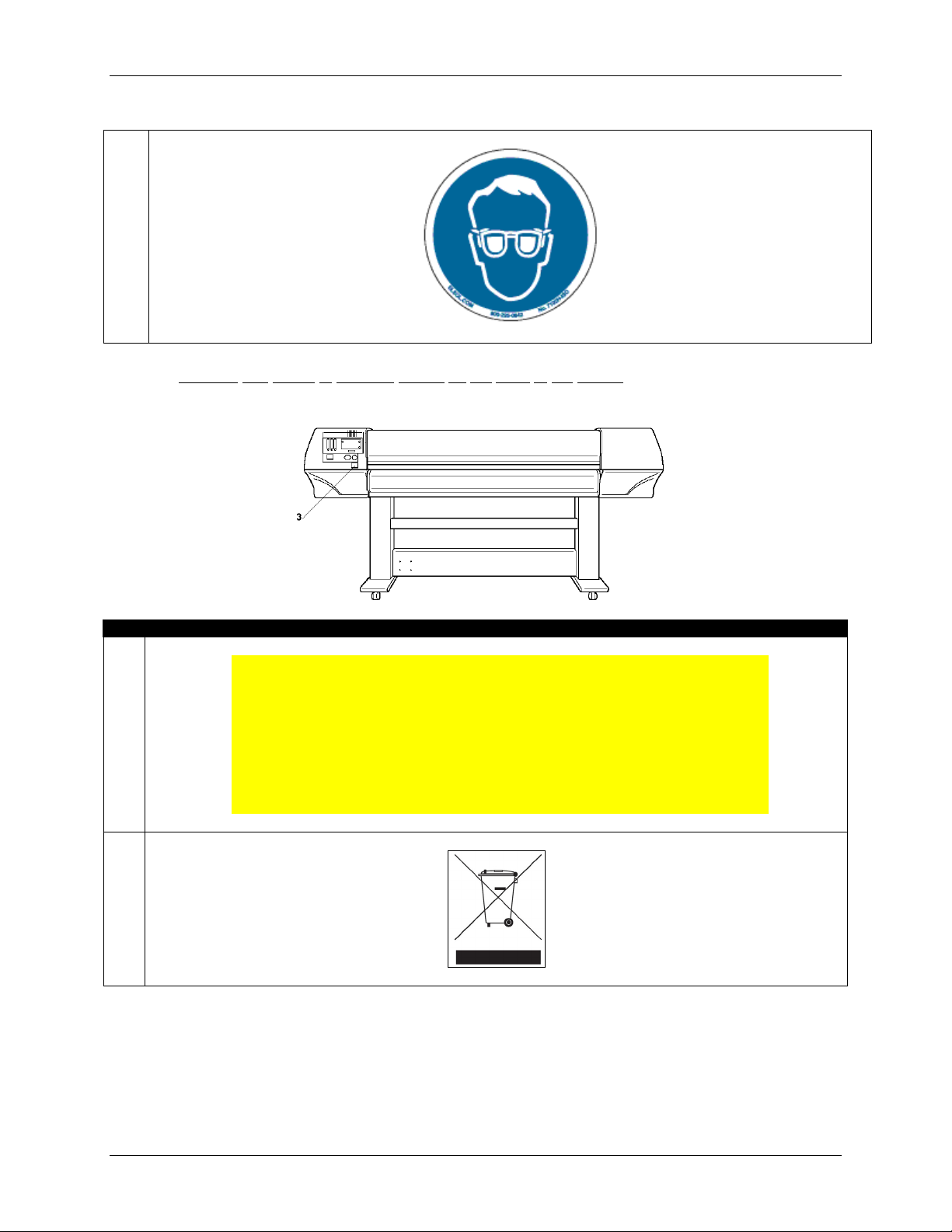
Disposal of your old product
Your product is designed and manufactured with high quality materials and components, which can be
recycled and reused.
When this crossed-out wheeled bin symbol is attached to a product it means the product is covered by
the European Directive 2002/96/EC
Please inform yourself about the local separate collection system for electrical and electronic products.
Please act according to your local rules and do not dispose of your old products with your normal
household waste. The correct disposal of your old product will help prevent potential negative
consequences for the environment and human health.
Page 3

TABLE OF CONTENTS
1 Safety Instructions..................................................................................................... 1
1.1 Introduction ........................................................................................................... 1
1.2 Warnings, Cautions and Notes
1.3 Important Safety Instr
uctions ................................................................................ 1
1.4 Warning Labels ..................................................................................................... 4
1.4.1 Handling the Warning Labels........................................................................... 4
1.4.2 Locations and Types of Warning Labels.......................................................... 4
2 Printer Overvie
w......................................................................................................... 9
2.1 Features................................................................................................................ 9
2.2 Part Names and Functions.................................................................................. 10
2.2.1 Front of Pri
nter............................................................................................... 10
2.2.2 Rear of Printer ............................................................................................... 11
2.2.3 Position and Function of the Heating Elements
2.2.4 Printer Control Panel
..................................................................................... 13
2.2.5 Winder (Front)................................................................................................ 15
2.2.6 Unwinder (Rear) ............................................................................................ 15
2.2.7 Winder/Un-winder Control Panel ................................................................... 16
2.2.8 Winder/Un-winder Operation Labels.............................................................. 17
3 Printer Setup............................................................................................................. 19
3.1 Turning the Printer Power ON/OFF..................................................................... 19
3.1.1 Turning the Power ON ................................................................................... 19
3.1.2 Turning the Power OFF ................................................................................. 19
3.2 Turning the Winder/Un-winder Power ON / OFF................................................. 21
3.3 Connecting the Network Interface....................................................................... 22
3.4 Media Handling ................................................................................................... 23
3.4.1 Loading Sheet Media
3.4.2 Loading Roll Media
3.4.3 Setting Media Type
3.5 Test Printing
........................................................................................................ 29
..................................................................................... 23
........................................................................................ 25
........................................................................................ 28
3.5.1 Setup List....................................................................................................... 31
3.5.2 Nozzle Check
................................................................................................. 32
3.5.3 Colour Palette ................................................................................................ 33
3.5.4 Maintenance Record...................................................................................... 34
4 Printer Operation...................................................................................................... 35
4.1 Printer Status
...................................................................................................... 35
4.1.1 Normal ........................................................................................................... 35
4.1.2 Setting Menu Display..................................................................................... 35
4.1.3 Changing the Printer Status
4.2 Using Media
........................................................................................................ 37
4.2.1 Media Type.................................................................................................... 37
4.2.2 Cautions on Handling Media
............................................................................. 1
............................................. 12
........................................................................... 36
.......................................................................... 37
8265/8290/8365/8390 User Guide i
Page 4

4.2.3 Precaution on Storing Media.......................................................................... 38
4.2.4 Media Printing Area ....................................................................................... 38
4.3 Menu Overview ................................................................................................... 39
4.3.1 Setup Menu 1/7 ............................................................................................. 41
4.3.2 Setup Menu 2/7
4.3.3 Setup Menu 3/7
............................................................................................. 53
............................................................................................. 63
4.3.4 Setup Menu 4/7 ............................................................................................. 67
4.3.5 Setup Menu 5/7 ............................................................................................. 76
4.3.6 Setup Menu 6/7 ............................................................................................. 81
4.3.7 Setup Menu 7/7 ............................................................................................. 83
4.4 Operating from the Control panel........................................................................ 84
4.4.1 Feeding Media ............................................................................................... 84
4.4.2 Controlling the Heater Elements .................................................................... 85
4.4.3 Operating the Pressure Rollers...................................................................... 87
4.4.4 Print Mode Check .......................................................................................... 87
4.5 Control Panel During Printing.............................................................................. 88
4.5.1 Heaters are not Ready during Printing........................................................... 88
4.5.2 Heaters are Ready during Printing................................................................. 88
4.6 Operations After Printing..................................................................................... 90
4.6.1 Cutting Media................................................................................................. 90
5 Troubleshooting....................................................................................................... 91
5.1 Introduction ......................................................................................................... 91
5.2 Failures and Malfunctions of the Printer.............................................................. 91
5.3 Error Messages................................................................................................... 98
5.3.1 Status Messages ........................................................................................... 98
5.3.2 Error Message Display and Solutions............................................................ 99
5.3.3 Data Error Display and Solutions................................................................. 101
5.3.4 Command Error Display and Solutions........................................................ 101
5.3.5 Error Requiring a Printer Restart ................................................................. 102
5.4 When Media Jams Occur.................................................................................. 103
6 Maintenance
........................................................................................................... 105
6.1 Introduction ....................................................................................................... 105
6.2 8265/8290 Periodic Maintenance
6.2.1 Weekly Maintenance
................................................................................... 106
...................................................................... 105
6.2.2 Bi-weekly Maintenance................................................................................ 108
6.2.3 Monthly Maintenance................................................................................... 109
6.2.4 Semi-Annual Maintenance
........................................................................... 111
6.3 8365/8390 Periodic Maintenance...................................................................... 112
6.3.1 Daily Maintenance ....................................................................................... 113
6.3.2 Weekly Maintenance
................................................................................... 115
6.3.3 Bi-weekly Maintenance................................................................................ 117
6.3.4 Monthly Maintenance
................................................................................... 118
6.4 Authorized Service Procedures......................................................................... 120
6.5 Replacing Consumables
6.5.1 Replacing Ink Cassettes
6.5.2 Replacing the Cutting Blade
................................................................................... 121
.............................................................................. 121
........................................................................ 124
ii 8265/8290/8365/8390 User Guide
Page 5

6.5.3 Replacing the Waste Tank........................................................................... 126
6.6 Cleaning............................................................................................................ 127
6.6.1 Cleaning the Outer Case ............................................................................. 127
6.6.2 Cleaning the Inside of the Printer................................................................. 128
6.6.3 Head Cleaning
6.7 LongStore Procedure
............................................................................................. 128
........................................................................................ 131
6.7.1 Ready the Printer for LongStore .................................................................. 131
6.7.2 Starting up after a LongStore....................................................................... 131
7 Adjustments ........................................................................................................... 133
7.1 Uni-Directional Adjustment................................................................................ 133
7.2 Bi-Directional Adjustment.................................................................................. 135
7.3 Step Adjustment................................................................................................ 137
7.3.1 Print the Dist.Check Test Pattern................................................................. 137
7.3.2 Evaluate the Dist. Check Test Pattern ......................................................... 138
7.3.3 Modify the Step Adjust Printer Setting ......................................................... 139
8 Appendix................................................................................................................. 141
8.1 Product Specifications ...................................................................................... 141
8.2 Network Interface Specifications....................................................................... 141
8265/8290/8365/8390 User Guide iii
Page 6

This page has been intentionally left blank.
iv 8265/8290/8365/8390 User Guide
Page 7
1 SAFETY INSTRUCTIONS
1.1 INTRODUCTION
This chapter explains the meaning of safety terms for personnel who operate this equipment, important
safety instructions, and the positions of the warning labels.
Be sure to follow all instructions and warnings in this manual when using the equipment.
1.2 WARNINGS, CAUTIONS AND NOTES
Safety terms in this manual and the contents of warning labels attached to the printer are categorized into
the following three types depending on the degree of risk (or the scale of accident).
Read the following explanations carefully and follow the instructions in this manual.
Safety terms Details
Important
Caution
Notes
Important
Must be followed carefully to avoid death or serious bodily injury
Must be observed to avoid bodily injury (moderate or light) or damage to your equipment
Contains important information and useful tips on the operation of your printer
1.3 IMPORTANT SAFETY INSTRUCTIONS
General safety instructions that must be observed to use the equipment safely are explained below.
Do not place the printer in the following areas. Doing so may result in the printer tipping or falling
over and causing injury.
{ Unstable surfaces
{ Sloping floors
{ Areas subject to vibration by other equipment
Do not stand on or place heavy objects on your printer. Doing so may result in the printer tipping or
falling over and causing injury.
Do not cover the ventilation hole of your printer with cloth, such as a blanket or table cloth. Doing so
could obstruct ventilation and cause fire.
Do not place the printer in humid and dusty areas. Doing so may result in electrical shock or fire.
Do not use a damaged power cable. Doing so may result in electrical shock.
Do not attempt to plug in electrical plugs with wet hands. Doing so may result in electrical shock.
Do not connect earth cables in the following areas.
{ Gas pipes Doing so may cause fire or an explosion.
8265/8290/8365/8390 User Guide 1
Page 8

1 Safety Instructions
{ Earth terminals for telephone line or lightening rod Doing so may cause a large flow of voltage if
lightening occurs.
{ Water pipes or faucets If there is a plastic part in the pipe, the earth will not work properly.
Do not insert or drop metal or inflammable objects into openings, such as ventilation outlets. Doing
so may result in electrical shock and fire.
Stop using your printer if a liquid has been spilled into it. This may cause electrical shock or fire.
Turn the printer off as soon as possible, unplug the power cord, and contact your local Xerox
Customer Service Representative.
Be sure to use the attached cable. Otherwise, electrical shock or fire may occur.
Be sure to use the specified voltage (AC 100 V to 120V, or AC 220V to 240V). Otherwise, electrical
shock or fire may occur.
Use electricity directly from a power outlet (AC 100 V to 120V, or AC 220V to 240V). Do not put
many loads on one electrical output. Otherwise, heat may be generated and cause fire.
Be sure to use an outlet with an earth terminal and use the terminal correctly. Otherwise, electrical
shock or fire may occur.
Follow the instructions below when handling the power cable.
{ Do not modify the cable.
{ Do not put heavy objects on the cable.
{ Do not bend, twist or pull the cable.
{ Do not wire the cable near equipment that generates heat.
Follow the instructions below when handling the power plug. Otherwise, fire may occur.
{ Wipe away dust and any other residue before inserting the plug.
{ Ensure that the plug is firmly inserted as far as it can go.
When handling the foot switch, be aware of the following:
{ Do not place anything heavy on the foot switch.
{ Do not bend the cable of the foot switch with force and do not pull.
{ Do not place the foot switch near thermal devices.
When handling ink cassettes, be careful that ink does not get in your eyes or on your skin. However,
if this happens, flush immediately with water and wash skin with soap. Otherwise, your eyes may
become congested or inflamed slightly. If you feel discomfort, consult a doctor immediately.
Do not disassemble ink cassettes. Otherwise, ink may get in your eyes or on your skin.
8265/8290/8365/8390 Inks
{ General information:
Symptoms of poisoning may even occur after several hours; therefore medical observation for at
least 48 hours after the accident.
After inhalation
:
Supply fresh air. If required, provide artificial respiration. Keep patient warm. Consult doctor if
symptoms persist.
In case of unconsciousness, place patient stably in side position for transportation.
After skin contact
After eye contact
After swallowing
: the product does not irritate the skin.
: Rinse opened eye for several minutes under running water.
: medical advice or consult doctor.
2 8265/8290/8365/8390 User Guide
Page 9

1 Safety Instructions
Be careful not to pinch your fingers when opening and closing the cover of the ink compartment.
Be careful not to pinch your fingers when opening and closing the front cover.
Follow the instructions below when connecting the network interface cable. Otherwise, electrical
shock or fire may occur.
{ Do not touch the connector.
{ Do not connect the network cable connector which has not the same specifications as the
interface board.
When cutting the roll media, be careful of the following. Incorrect handling can result in injury to the
hands and fingers from the razor blade.
{ When holding the media, do not place fingers over the media cut groove.
{ Move the razor blade slowly along the media cutting groove.
Do not use thinner, benzene, alcohol or other active agents. Doing so may result in damage or paint
peeling from the casing.
Be careful not to spill water inside the printer. Doing so may result in a short circuit.
Be careful not to touch the heaters during or after operation. Doing so may result in burns.
Only use Xeror Ink and appropriate cleaning liquid.
Never open the covers fixed with screws, except the left cover. Doing so may result in electrical
shock or a malfunctioning of the printer.
Do not touch the cutter blade. Doing so may result in bodily injury.
Do not cut hard objects or drop the cutter. Doing so may damage or chip the cutter blade.
Do not bend or pull the waste fluid tube. Doing so may cause that the waste fluid will leak out and
malfunction of the product.
Do not touch the cleaning wiper or the head cap unit with bare hands. Use a dust free cloth and
gloves to clean.
Do not tilt the printer, stand it against a wall or turn it upside down. Doing so may cause ink to leak
inside the printer. Movement after transport is also not covered by the warranty.
The equipment that you bought requires the extraction and use of natural resources for its production.
It may content hazardous substances for the health and the environment. In order to avoid the
dissemination of those substances in our environment and to diminish the pressure on the natural
resources, we encourage you to use the appropriate take-back system. Those systems will re-use or
recycle most of the materials of your end life equipment in a sound way. If you need more
information on the collection, re-use and recycling systems, please contact your local or regional
waste administration.
8265/8290/8365/8390 User Guide 3
Page 10
1 Safety Instructions
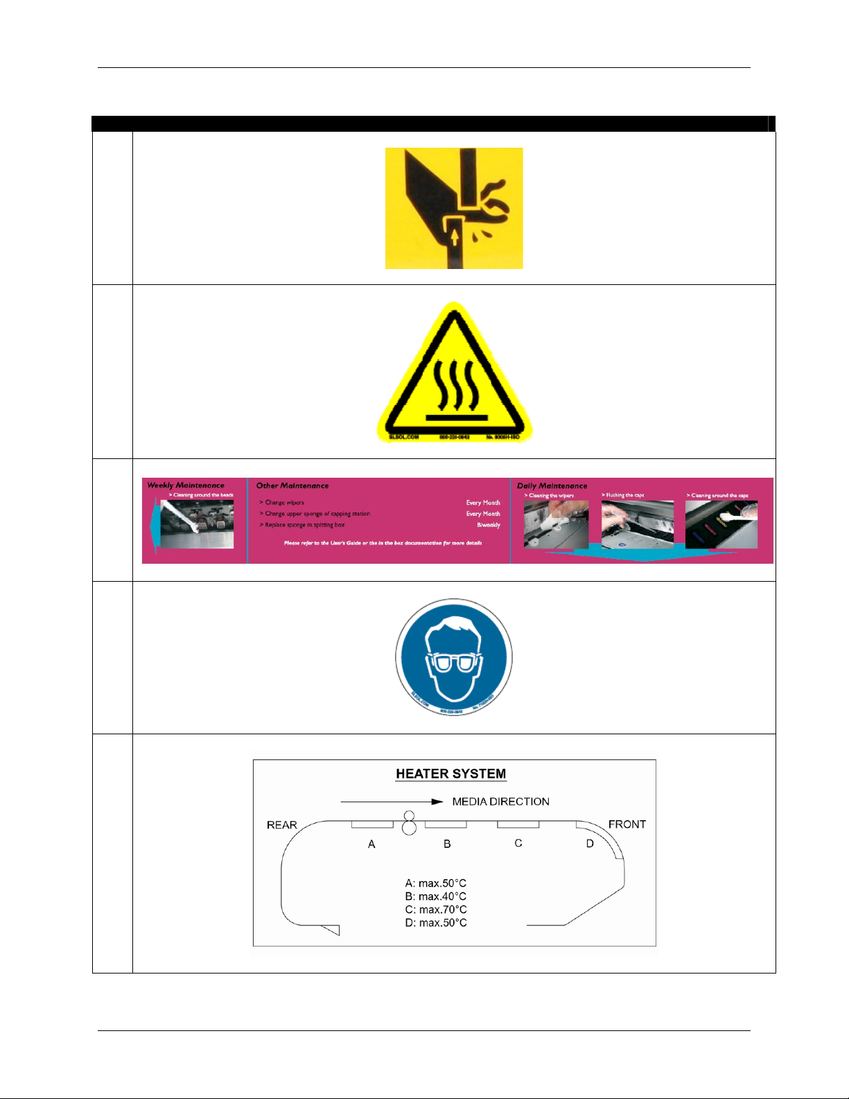
1.4 WARNING LABELS
The handling, attachment locations, and types of warning labels are explained below.
Warning labels are attached on areas which require attention. Read and understand the positions and
contents thoroughly before performing your work.
1.4.1 Handling the Warning Labels
Be sure to note the following when handling the labels.
Make sure that all labels can be recognized. If text or illustrations cannot be seen clearly, either clean
or replace the label.
When cleaning labels, use a cloth with water or neutral detergent. Do not use a solvent or gasoline.
If a warning label is damaged, lost or cannot be recognized, replace the label. When replacing warning
labels, contact your local Xerox Customer Service Representative.
Notes
1.4.2 Locations and Types of Warning Labels
The locations of warning labels are shown below.
1.4.2.1 Location
and Types of Warning Labels on the Front of the Printer
4 8265/8290/8365/8390 User Guide
Page 11
No Type
1
1 Safety Instructions
2
3
4
5
8265/8290/8365/8390 User Guide 5
Page 12
1 Safety Instructions
6
7
8
9
6 8265/8290/8365/8390 User Guide
Page 13
10
1 Safety Instructions
1.4.2.2 Location
No Type
3
4
and Types of Warning Labels on the Rear of the Printer
CAUTION
THIS UNIT HAS TWO POWER SUPPLY CORDS, WHEN WINDING
UNIT IS PROVIDED. TO REDUCE THE RISK OF ELECTRICAL
SHOCK, DISCONNECT ALL POWER SUPPLY CORDS
BEFORE SERVICING.
8265/8290/8365/8390 User Guide 7
Page 14

1 Safety Instructions
This page has been intentionally left blank.
8 8265/8290/8365/8390 User Guide
Page 15

2 PRINTER OVERVIEW
2.1 FEATURES
The features of the printer are explained below.
(1) High speed output
Achieve high speed printing, maximum media width of 2280 mm and printing width up to 2250 mm.
(2) Wide variety of compatible media
Adjustable head height can be adapted to various media thickness from 0.08 up to 1.1 mm.
(3) Vibrant Colour Reproduction
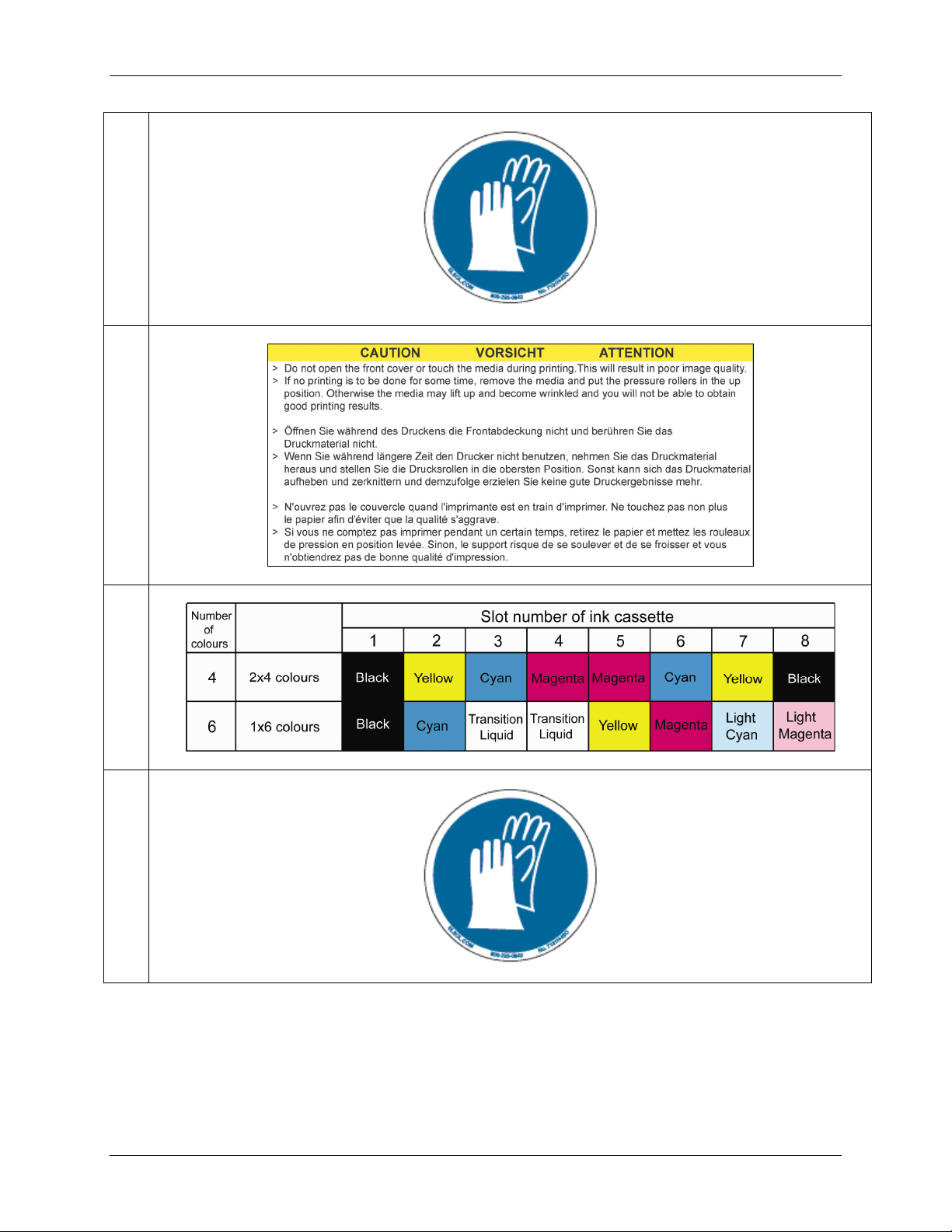
To reproduce sharp and vivid colour, either 4 or 6 ink colours are used for printing. Ink cassette come in
either 220ml or 440ml capacity with an IC chip that tracks the ink quantity in the cassette, significantly
improving productivity.
(4) Effective usage of media
A media feed feature is provided allowing the user to feed media forward or backward to set the printing
position. Because printing can be performed on media on which there has already been printed, excess
space can be used effectively.
8265/8290/8365/8390 User Guide 9
Page 16
2 Printer Overview
2.2 PART NAMES AND FUNCTIONS
Part names and functions are explained below.
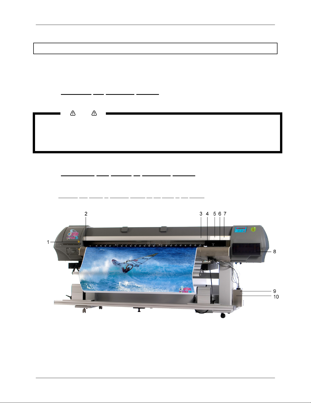
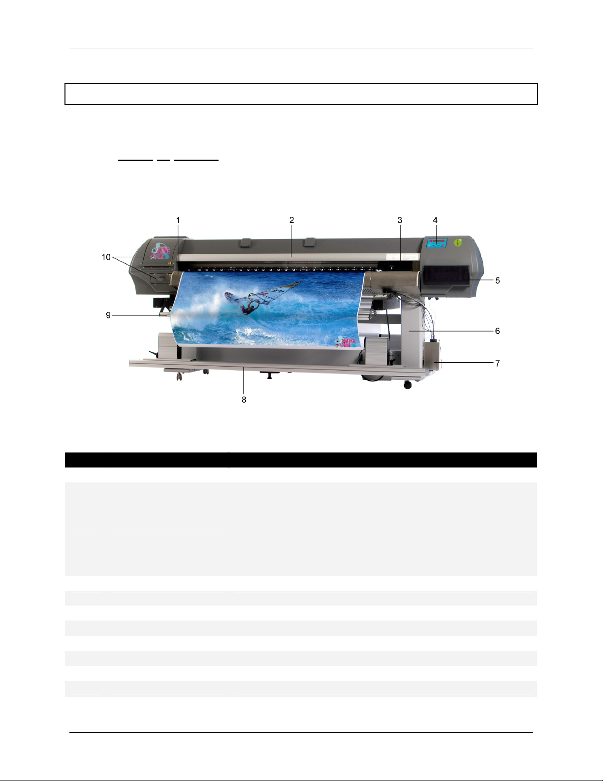
2.2.1 Front of Printer
No Name Function
Heater plate Supports and heats the media during printing.
1
Keeps the operator safe from the drive parts of the printer while it is
operating. Only open and/or close the cover to perform following
Front cover
2
Carriage Drives and holds the print heads.
3
Operation panel To control the printer.
4
Ink compartment cover Covers the ink compartment.
5
Stand Carries the main body.
6
Waste bottle assembly Collects the waste fluid.
7
Winder Rolls up the roll media.
8
Front tension system Keeps the media under tension.
9
10
Left maintenance covers. Covers the maintenance areas.
operations:
Media setting and replacement
Cutter blade replacement
Cleaning the cleaning wiper
10 8265/8290/8365/8390 User Guide
Page 17
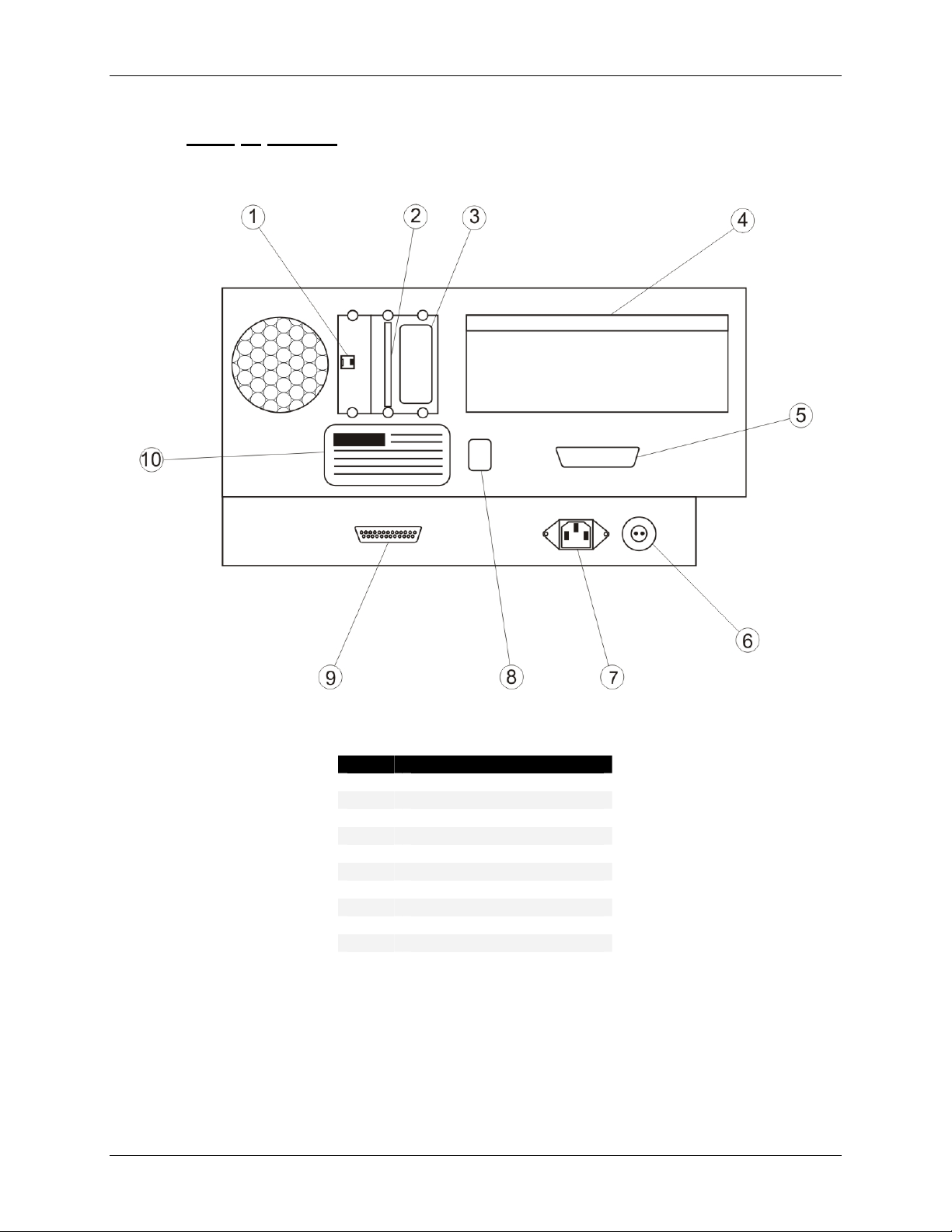
2.2.2 Rear of Printer
2 Printer Overview
No Connection
Ethernet connector
1
Card reader slot
2
SmartChip label
3
Bracket Cover
4
Centronics connector
5
Foot switch connector
6
Power inlet
7
Environmental label
8
DB-25 connector
9
10
ID label
8265/8290/8365/8390 User Guide 11
Page 18
2 Printer Overview
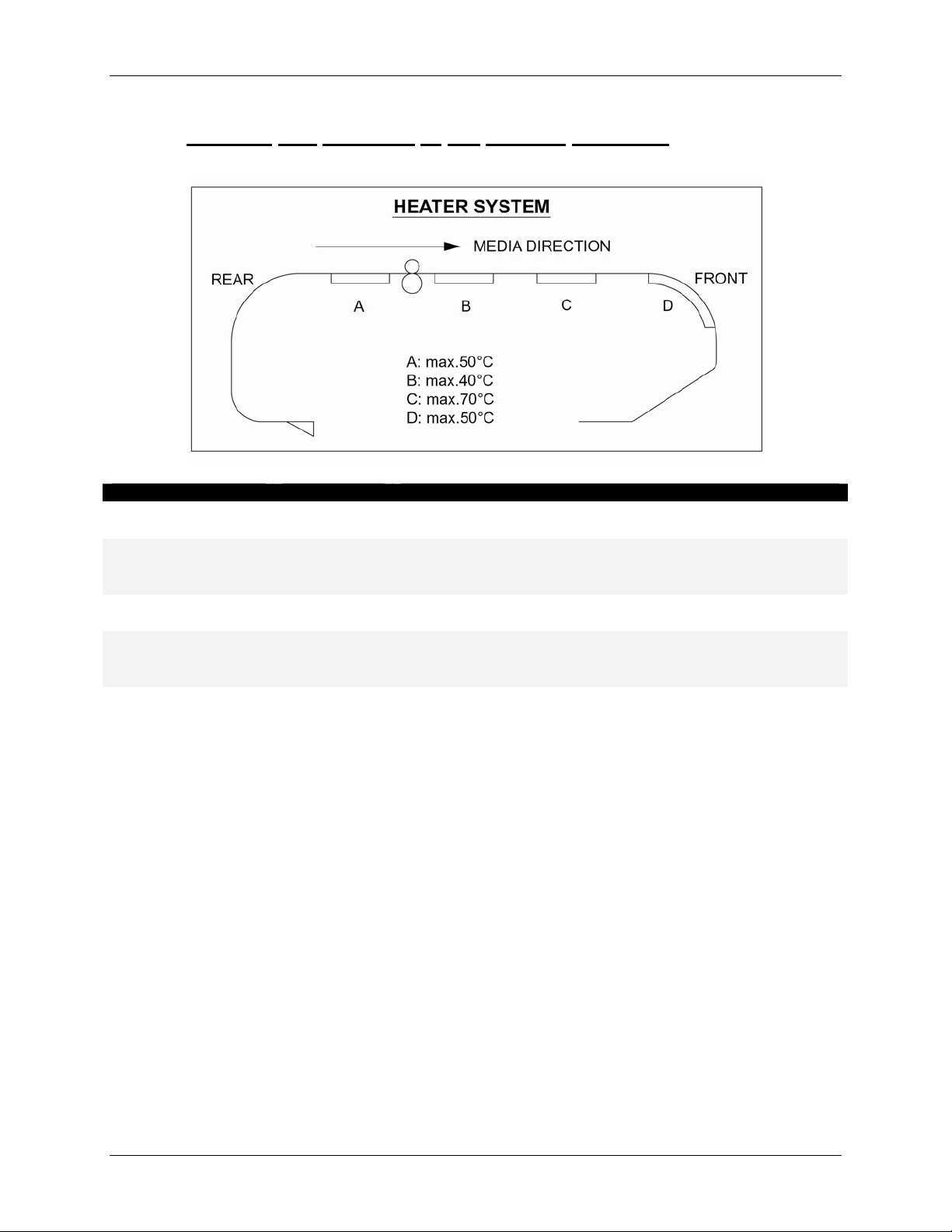
2.2.3 Position and Function of the Heating Elements
Heater element Temperature Function
Pre-heater (Heater A) 20 – 50°C
Open the pores to make the media more receptive for
8365/8390 Mild Solvent Ink.
To establish optimum fixation onto the media (coated and
Fixer (Heater B) 20 – 40°C
uncoated).
Optimizes the dot gain control.
Post-Fixer (Heater C) 20 – 70°C
The post-fixer finalizes the fixation process and helps to
make the prints touch-dry.
The dryer completes the drying for compatibility with the
Dryer (Heater D) 20 – 50°C
take-up in combination with higher output speeds.
Stickiness of printed banner materials is improved.
For user 1 and user 8 default settings are as follows:
{ Pre heater A: 50°C
{ Fixer B: 40°C
{ Post Fixer C: 50°C
{ Dryer D: 50°C
For users 2 Î 7, by default the heaters are still OFF.
12 8265/8290/8365/8390 User Guide
Page 19
2 Printer Overview
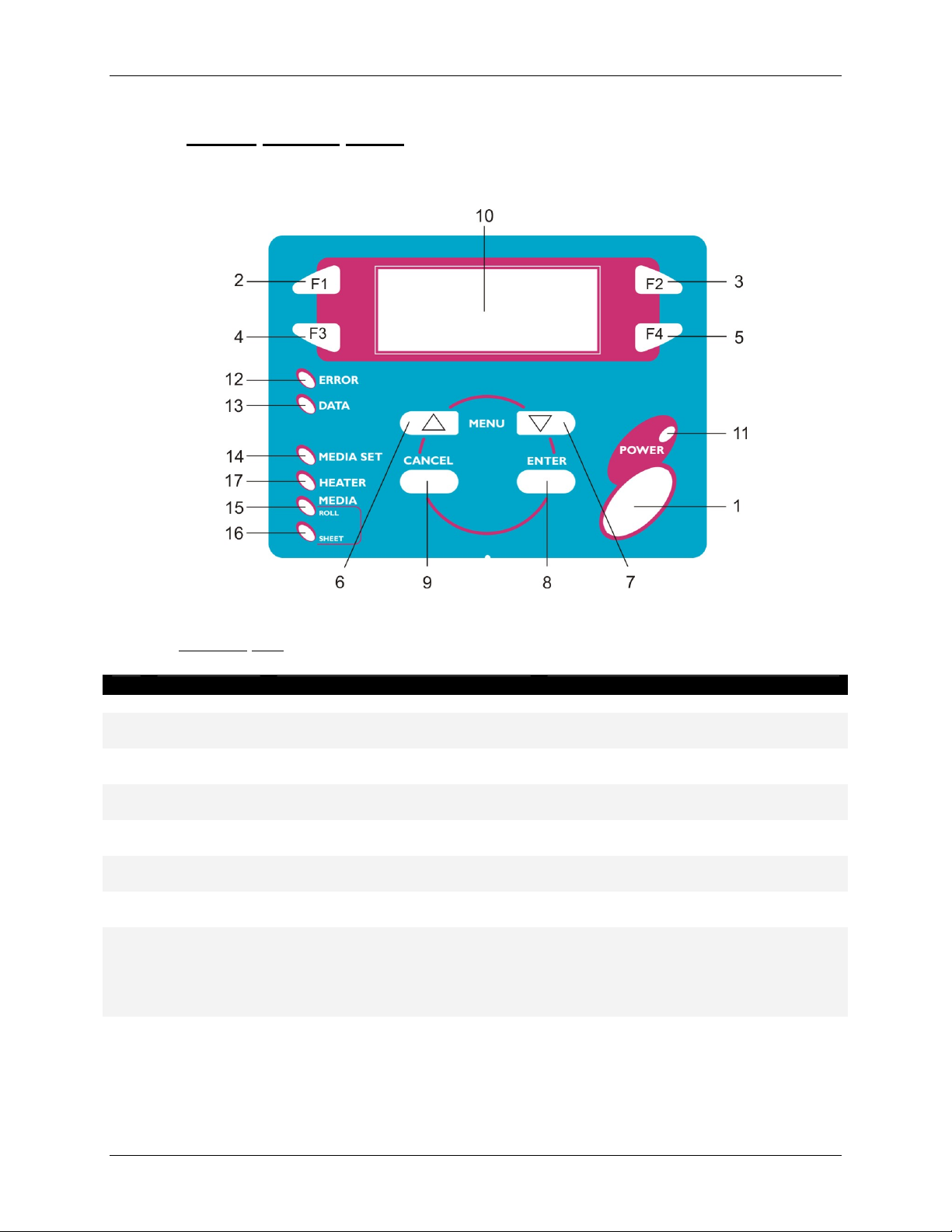
2.2.4 Printer Control Panel
The operation panel is used to set operational conditions, display the status of the printer, and set other
functions. The names and functions of the operation keys and status lamps are explained below.
2.2.4.1 Operation
No Name Normal Setup menu display
[POWER] key Turns the printer on and off. Turns the printer on and off.
1
[F1] key Executes the function assigned to
2
[F2] key Executes the function assigned to
3
[F3] key Executes the function assigned to
4
[F4] key Executes the function assigned to
5
6
[MENU ] key
7
[MENU ] key
[ENTER] key Displays the print mode currently
8
[CANCEL] key - Cancels the new parameter value and
9
keys
F1.
F2.
F3.
F4.
Changes the LCD monitor display to
the setup menu status.
Changes the LCD monitor display to
setup menu status.
set.
Executes the function assigned to F1.
Executes the function assigned to F2.
Executes the function assigned to F3.
Executes the function assigned to F4.
Changes the menu in reverse order.
Changes the menu in forward order.
Determines the new parameter value and
changes the LCD monitor display to the
next menu. Sets the parameter value and
changes the LCD monitor display to the
next menu.
changes the LCD monitor display to the
next menu. Clears the parameter value
and changes the LCD monitor display to
the next menu.
8265/8290/8365/8390 User Guide 13
Page 20

2 Printer Overview
2.2.4.2 LCD Monitor and Light Indicators
No Name Colour Status Function
LCD monitor - - The monitor displays the operation status and error
10
messages of the printer.
POWER lamp Green
11
ON The printer is on.
OFF The printer is off.
ERROR lamp Red
12
Flashing An error has occurred. The contents will be displayed on
the LCD monitor.
OFF Either there is no error or the power is off.
DATA lamp Orange
13
ON The printer is receiving print data.
Flashing The printer is analyzing received data.
OFF The printer is waiting to receive print data.
14
MEDIA SET
lamp
Orange
ON The pressure roller is in the release position.
Media has not been loaded.
OFF The pressure roller is in the secured position.
The media has not been loaded.
ROLL lamp Orange
15
ON The media type is set to roll media.
OFF The media type is set to sheet media.
SHEET lamp Orange
16
ON The media type is set to sheet media.
OFF The media type is set to roll media.
HEATER lamp Orange
17
ON The temperature of the heating elements is the requested
temperature.
The real temperature is the same as the requested
temperature.
Flashing The heating elements are warming up.
The real temperature is different as the requested
temperature.
OFF The heating elements are powered OFF.
14 8265/8290/8365/8390 User Guide
Page 21
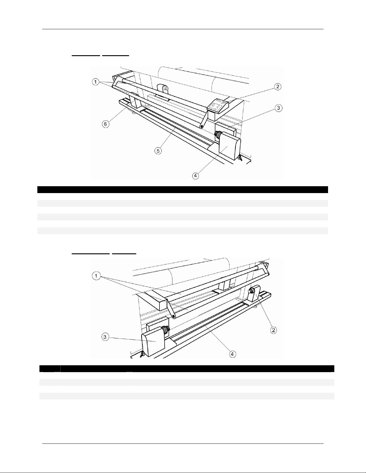
2.2.5 Winder (Front)
2 Printer Overview
No Name Function
Front tensioning system Adjust the tension between the print platform and the winding system.
1
Operation panel To control the unwinder winder 100 manually or automatically
2
PCB Box Contains the boards to control the UW/W 100.
3
Motorized roll unit Supports and winds up the roll media.
4
Roll unit bar Supports the roll units.
5
Roll unit Supports the roll media.
6
2.2.6 Unwinder (Rear)
No Name Function
Rear tensioning system Adjust the tension between the print platform and the unwinding system.
1
Roll unit Supports the roll media.
2
Motorized roll unit Supports and unwinds the roll media.
3
Roll unit bar Supports the roll units.
4
8265/8290/8365/8390 User Guide 15
Page 22
2 Printer Overview
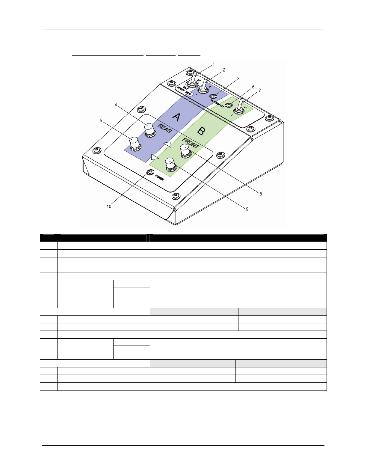
2.2.7 Winder/Un-winder Control Panel
No. Name Function
A / Part of the operation panel controlling the unwinder 100.
B / Part of the operation panel controlling the winder 100.
1 Print Side Selector
2 Unwinder 100 switch Toggle between Manual (“0”) and Automatic (“I”) mode.
Manual
Unwinder 100
3
LED
Outside printing Inside printing
4 Backwards button Roll-off unwinder Roll-up unwinder
5 Forwards button Roll-up unwinder Roll-off unwinder
6 Winder 100 switch Toggle between Manual (“0”) and Automatic (“I”) mode.
7 Winder 100 LED
Outside printing Inside printing
8 Backwards button Roll-off winder Roll-off winder
9 Forwards button Roll-up winder Roll-up winder
10 Power LED Lightens up if the system is powered ON.
Automatic
Manual
Automatic
In case you loaded media with printed side on the outside select
‘OUT’, otherwise select ‘IN’.
LED lights up when pushing one of the buttons
Motor turns: LED flashes.
Motor is off: LED is out.
Motor accelerates: LED burns continuously.
LED lights up when pushing one of the buttons
Motor turns: LED flashes
Motor is off: LED is out.
16 8265/8290/8365/8390 User Guide
Page 23
2 Printer Overview
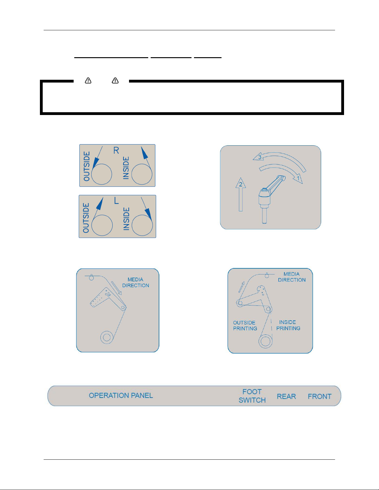
2.2.8 Winder/Un-winder Operation Labels
The operation labels mentioned below are attached to areas to which attention should be paid.
Make sure that all labels can be recognized. If text or illustrations are invisible, clean the label.
When cleaning labels, use a cloth with water or neutral detergent. Do not use a solvent or gasoline.
If an operation label has been damaged, lost or cannot be recognized, replace the label.
Notes
Foot switch label Roll unit handle label
Front tensioning label
Rear tensioning label
PCB box label
8265/8290/8365/8390 User Guide 17
Page 24

2 Printer Overview
This page has been intentionally left blank.
18 8265/8290/8365/8390 User Guide
Page 25
3 PRINTER SETUP
3.1 TURNING THE PRINTER POWER ON/OFF
The method to turn the power ON or OFF is described below.
Before powering ON the unit, make sure the waste bottle is installed.
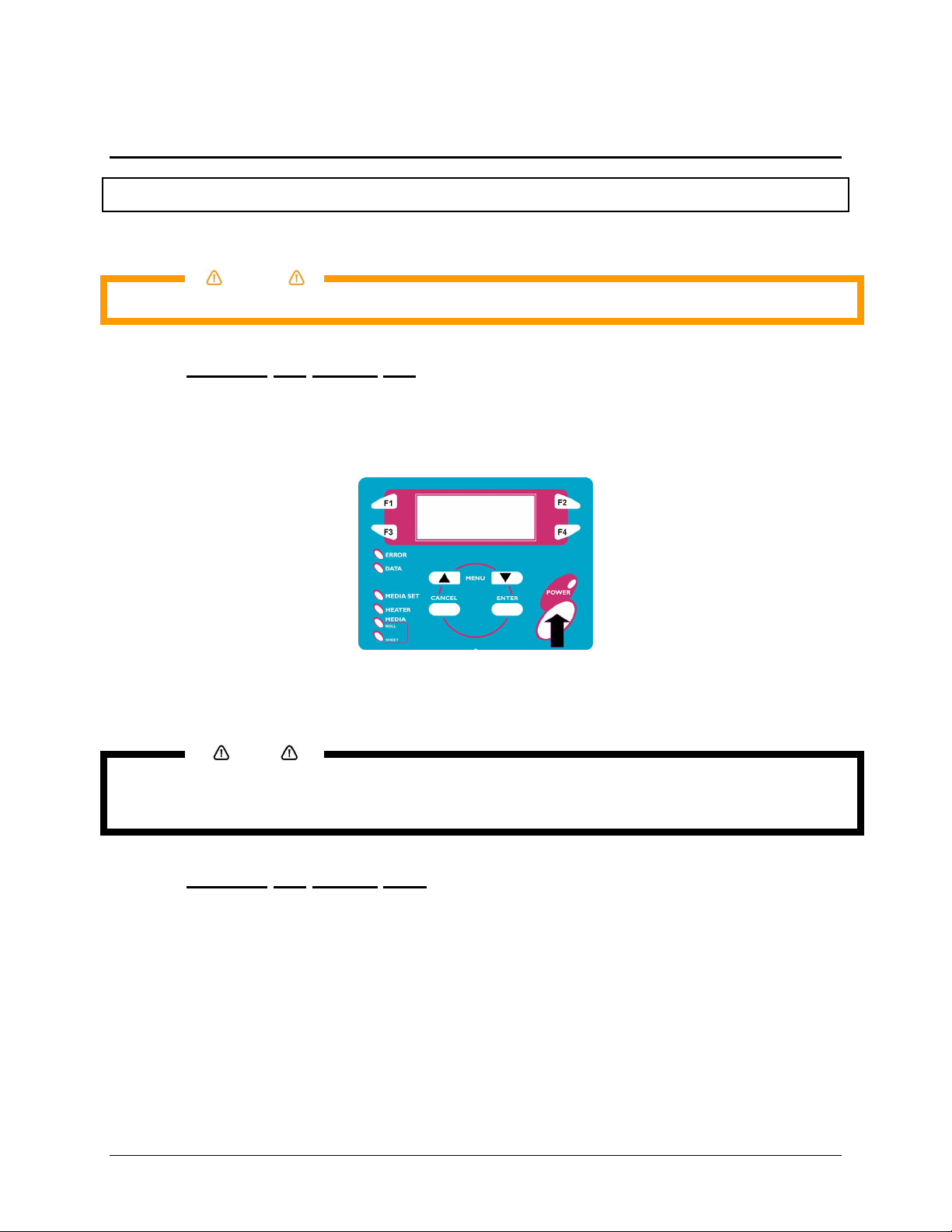
3.1.1 Turning the Power ON
Turn the power of the unit ON according to following procedure.
Step 1 : Press the [POWER] key of the operation panel, to turn the unit ON.
Caution
¾ The POWER lamp of the operation panel will light (green).
Step 2 : The unit will start initial start-up operations.
Step 3 : After finishing initial start-up operations, the unit will enter the normal operating condition.
Notes
If there are any problems during the initial start-up operation, the unit will display a message on the
operation panel, and the operation may stop. If the operation stops, refer to "Troubleshooting", and take
the appropriate actions.
3.1.2 Turning the Power OFF
Turn the power of the unit OFF according to the following procedure.
Step 1 : Verify the following regarding the operational condition of the unit.
¾ There is no printing operation being performed.
¾ The operation panel is in a normal status.
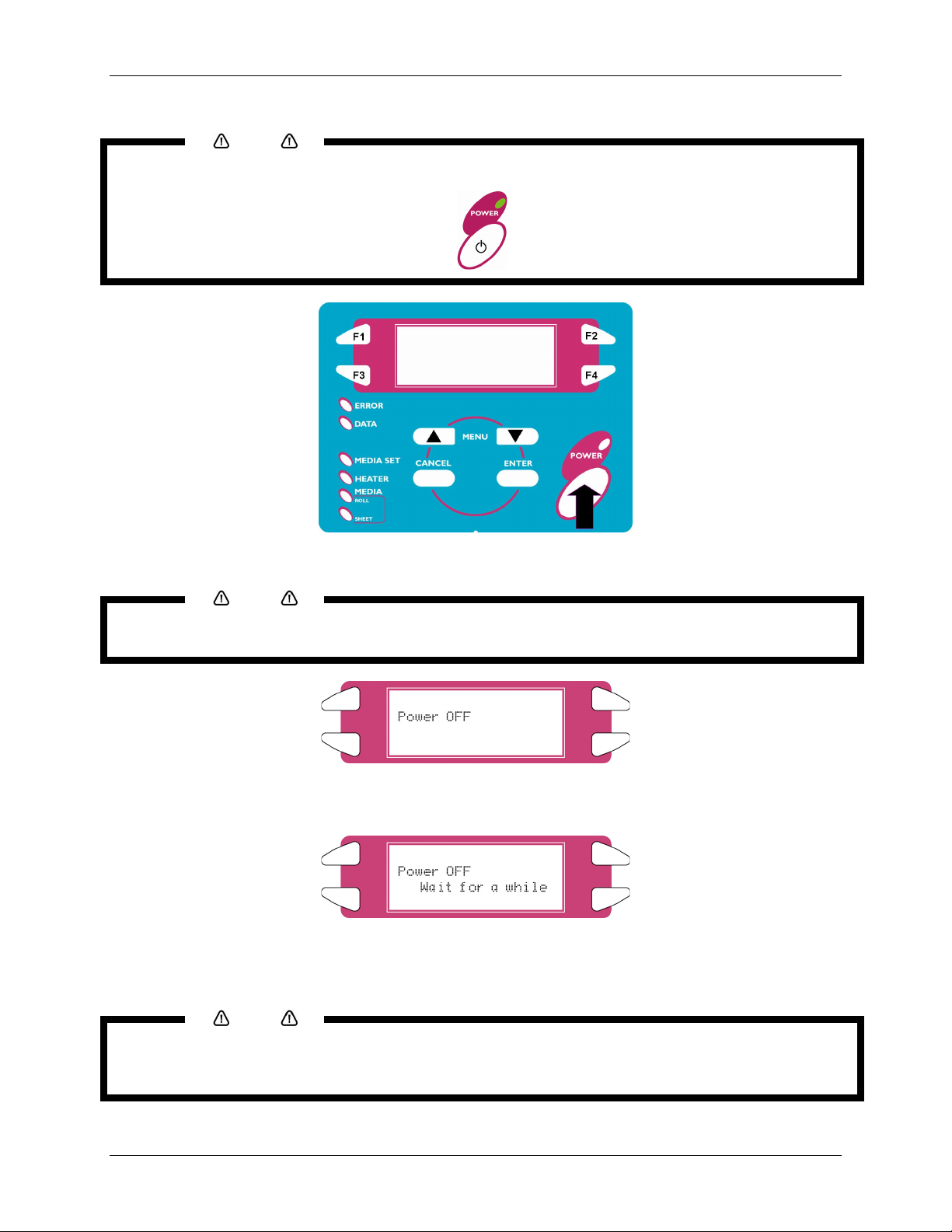
Step 2 : Press the [POWER] key of the operation panel to turn the unit OFF.
8265/8290/8365/8390 User Guide 19
Page 26
3 Printer Setup
Notes
When the printer is ON, the power LED is lid green. Push the power button again to turn off the machine.
Step 3 : Following message is displayed for 3 seconds on the operation panel.
If pressing the [POWER] key on the operation panel by mistake, press the [POWER] key again while the
following message is displayed.
Notes
Step 4 : The product will perform the power OFF operation.
¾ Following message is displayed on the operation panel.
¾ All lamps and the LCD of the operation panel will turn OFF.
¾ The product will automatically turn the power OFF after performing a tubing flush.
Notes
If there are problems during the power OFF operation, the unit will display a message on the operation
panel, and the operation may stop. If the operation stops, refer to “Troubleshooting” and take the
appropriate actions.
20 8265/8290/8365/8390 User Guide
Page 27
3 Printer Setup
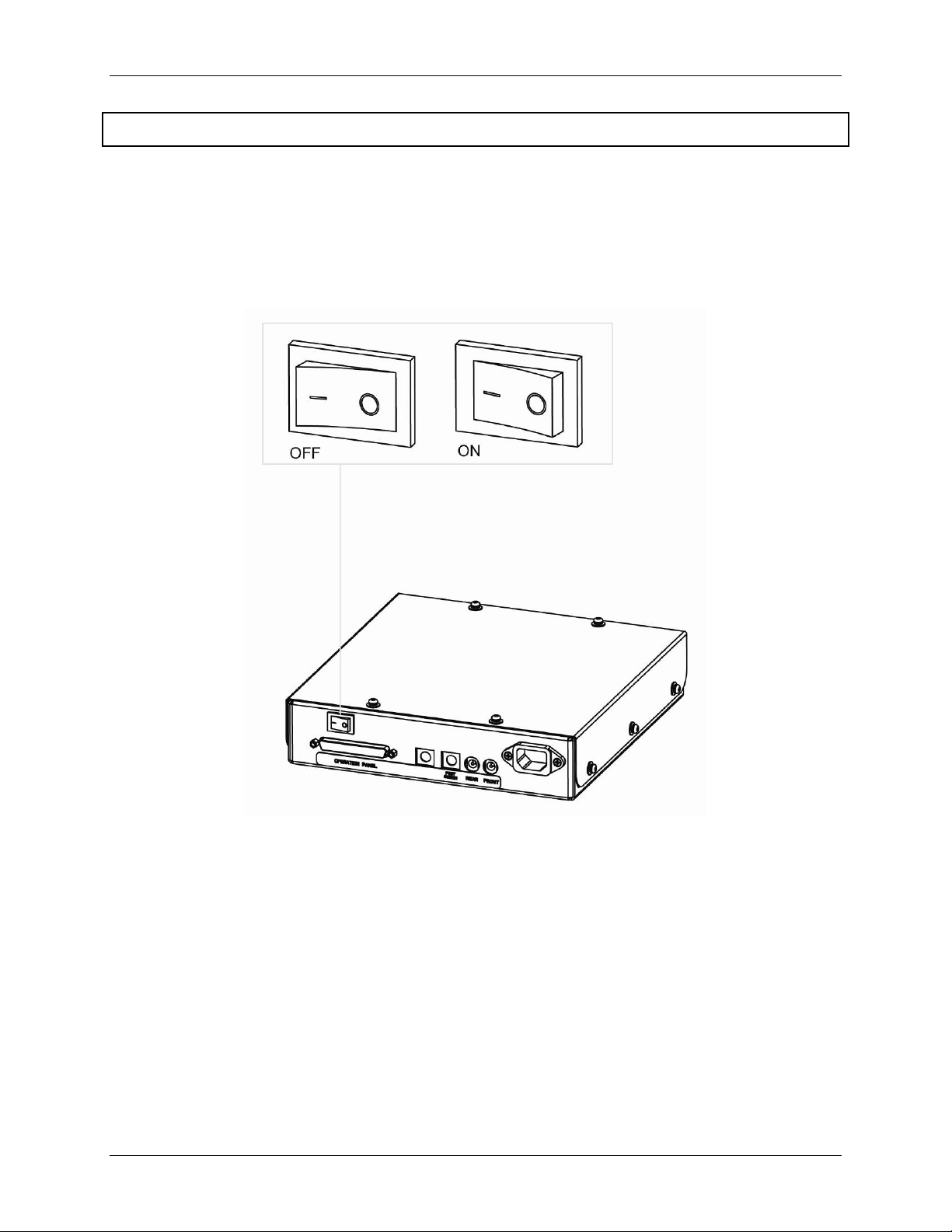
3.2 TURNING THE WINDER/UN-WINDER POWER ON / OFF
The switch in located on the power supply box.
Its status is marked with “O” and “I”.
“I” Switched ON Power LED on control panel of winding system will light up
“O” Switched OFF Power LED on control panel of winding system will not be lid.
8265/8290/8365/8390 User Guide 21
Page 28
3 Printer Setup
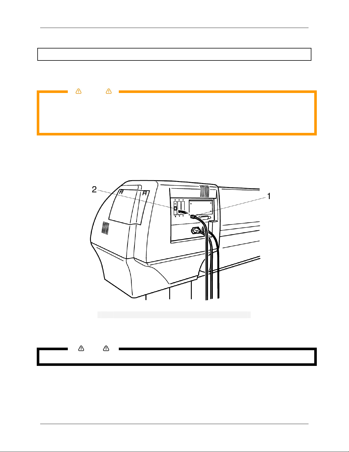
3.3 CONNECTING THE NETWORK INTERFACE
The procedure for connecting the network interface is explained below. To connect the printer to the
network environment, follow the steps below.
Follow the instructions below when connecting the network interface cable. Otherwise,
electrical shock or fire may occur.
o Do not touch the connector.
o Do not connect the network cable connector to the interface board having different
Step 1 : Turn off the printer.
Step 2 : Plug the connector of the Ethernet cable into the connector of the network interface board at
Caution
specifications.
the back of the printer.
1 Network interface connector
2 Interface cable
Step 3 : Connect the other end of the Ethernet cable to the network.
Refer to "Network interface board operation manual" to use the network interface board.
Notes
22 8265/8290/8365/8390 User Guide
Page 29
3.4 MEDIA HANDLING
Media handling, attaching media, and setting media type are explained below.
3.4.1 Loading Sheet Media
You can use the following sheet media with your printer.
Maximum Media Width
Printing Width Up To
To load sheet media, follow the steps below.
If roll media is attached to the printer, wind the media up and then load the sheet media.
Notes
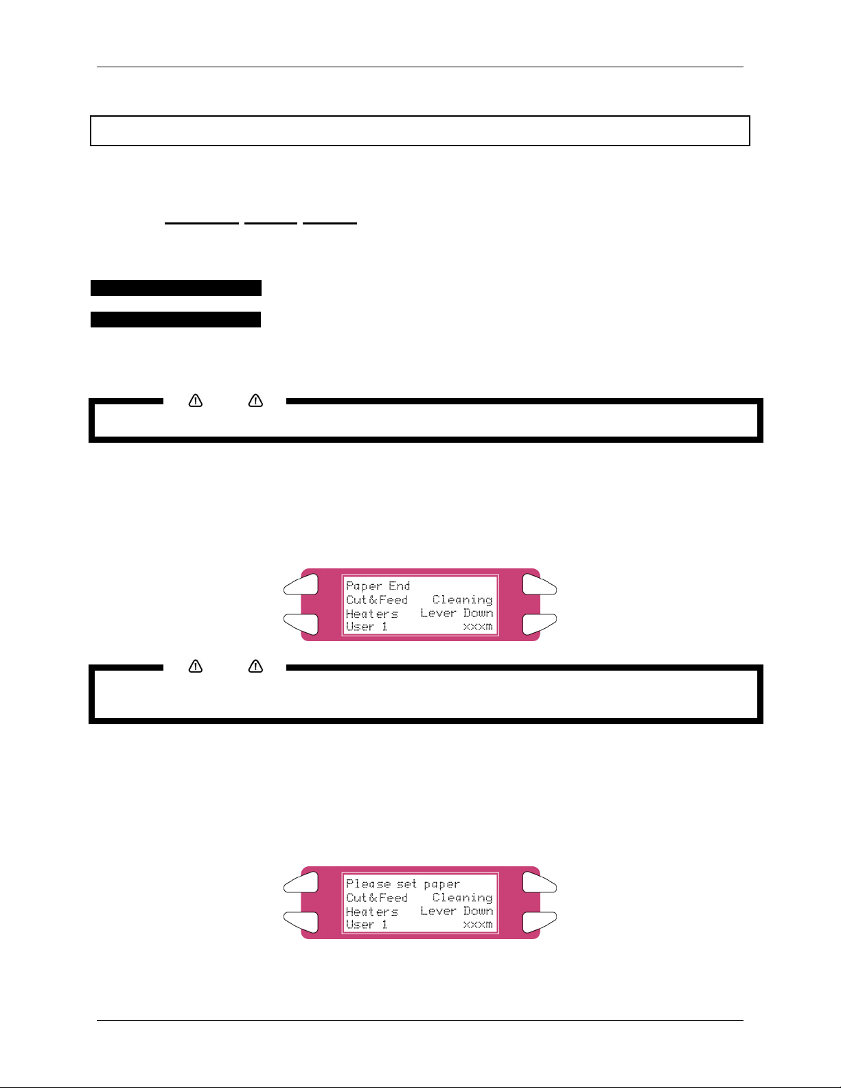
Step 1 : Turn the printer on.
Step 2 : The printer starts the initialize operation.
¾ The following message is displayed on the operation panel.
2280 mm
2250 mm
3 Printer Setup
Notes
If you do not want to use the media detection at the media initialization: Set to "OFF" in the media
detection setup item.
Step 3 : Verify if the sheet lamp on the operation panel is unlit.
Step 4 : Press the [F4] key on the operation panel to lower the pressure rollers.
¾ The MEDIA SET lamp will light (orange).
¾ The following message is displayed on the operation panel.
8265/8290/8365/8390 User Guide 23
Page 30
3 Printer Setup
When raising or lowering the pressurize rollers, you can use the foot switch instead of the operation panel.
Notes
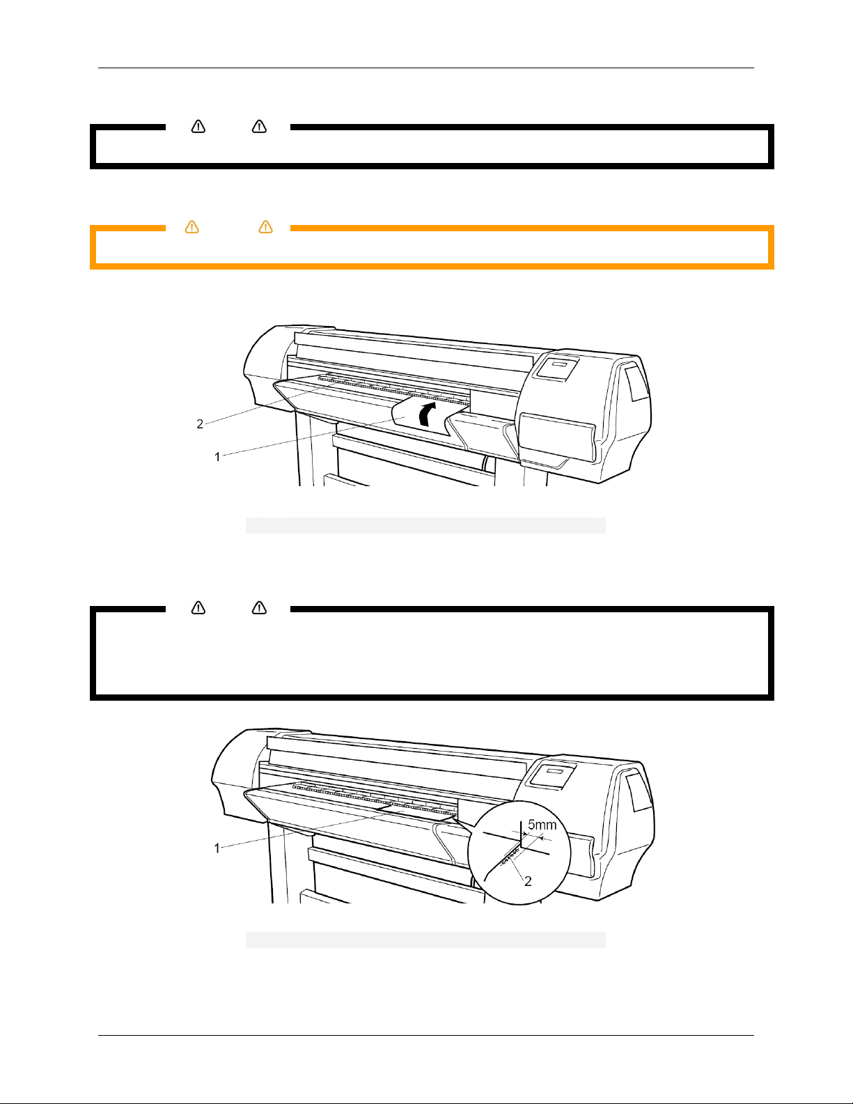
Step 5 : Open the front cover.
Be careful not to pinch your fingers when opening and closing the front cover.
Caution
Step 6 : Load the sheet media into the insertion slot at the front of the printer.
Sheet media
1
Insertion slot
2
Step 7 : Set the right edge of the media so that it is parallel with the media setting position.
Notes
The media set position is a guideline for setting up the media.
If the right edge of the sheet media is 5 mm or more from the media setting position, a media set error
may occur if the media is not detected. Make sure to set the right edge of the sheet media within 5
mm of the media setting position.
Sheet media
1
Media loading position
2
Step 8 : Press the [F4] key on the operation panel to lower the pressure rollers.
24 8265/8290/8365/8390 User Guide
Page 31

¾ The MEDIA SET lamp will turn off.
Step 9 : Close the front cover.
Step 10 : The media initial menu is displayed on the operation panel.
3 Printer Setup
3.4.2 Loading Roll Media
3.4.2.1 Installing the media roll
Step 1 : Determine the printable side of the media roll (inside or outside printing) and lay down the
media roll as shown in the images below.
Step 2 : Position the roll units of the unwinder in such a way that the media roll can be placed in
between.
1 = Roll unit handle
2 = Roll unit
3 = Media roll
Step 3 : Lock one roll unit to the roll unit bar
Step 4 : Place one side of the roll over the flange of the locked unit.
8265/8290/8365/8390 User Guide 25
Page 32

3 Printer Setup
Step 5 : Slide the flange of the other roll unit into the roll and lock the unit by using its handle.
Step 6 : You can now de-lock both sides to position the roll.
Step 7 : Set the right edge of the media on the Unwinder so that it is parallel with the media setting
position.
Roll media
1
Media setting position
2
We recommend wearing cotton gloves to avoid fingerprints on the inkjet media.
Notes
Step 8 : Lock both sides of the Unwinder.
3.4.2.2 Loading
the media into the printer
ART 1: INSTALLING AN EMPTY CORE AND LOADING THE MEDIA THROUGH THE REAR TENSIONING SYSTEM
P
Step 1 : Make sure the printer and UW/W 100 are ON.
Step 2 : Press the [F4] key to raise the pressure rollers.
Step 3 : Open the front cover.
Step 4 : Install an empty core between the motorized roll unit and roll unit of the winder unit on front of
the printer.
Make sure the core is longer than the media width.
Notes
Step 5 : Make sure both unwinder (REAR) and winder (FRONT) unit are set to MANUAL mode.
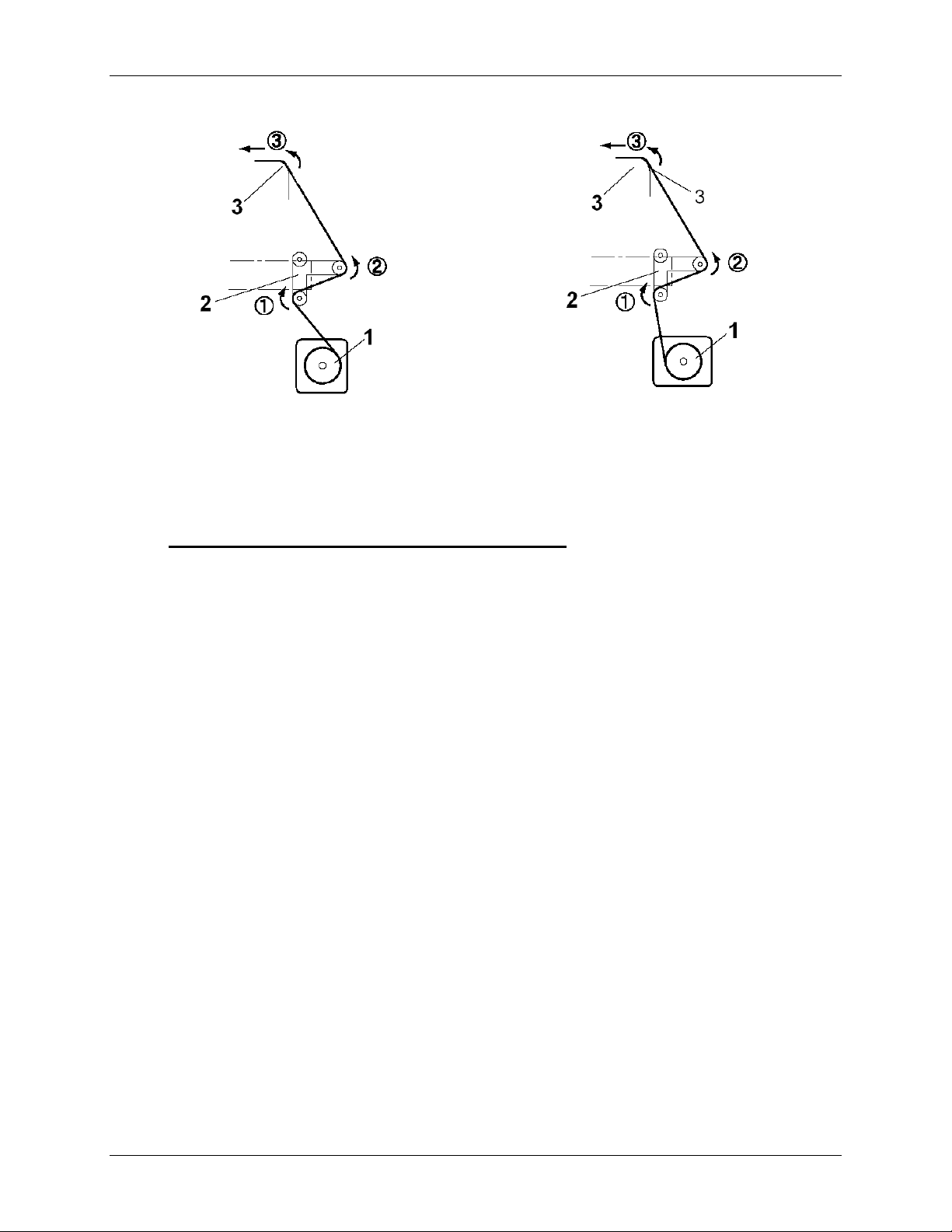
Step 6 : Use the foot-switch to release some media on the rear.
Step 7 : Load media through the rear tensioning system as shown below.
26 8265/8290/8365/8390 User Guide
Page 33
3 Printer Setup
Printable side on the outside of the roll Printable side on the inside of the roll
1 = Unwinder
2 = Rear tensioning system
3 = Media insertion slot of the printer
ART 2: LOADING THE MEDIA TROUGH THE FRONT TENSIONING SYSTEM
P
Step 1 : Load the media through the printer’s pressure rollers.
Step 2 : Standing in front of the printer, take the media and pull it until there is equal tension on the left
and right of the media.
Step 3 : Do not pull the media in the middle.
Step 4 : Lower the pressure rollers of the printer.
Step 5 : Set the unwinder (REAR) unit to AUTOMATIC.
Step 6 : The rear tensioning system will go to its initial position.
Step 7 : Close the front cover.
Step 8 : Start printing until the media reaches the front core of the winder OR feed the media without
printing.
Step 9 : Use tape to fix the media end to the empty core installed at the winder unit. Start taping the
middle of the media, then the both ends, applying equal tension on both ends.
Step 10 : Set the winder (FRONT) unit to ACTIVE. The front tensioning system will be activated.
Step 11 : Setup the printer to use the Winder. At the Printer Control Panel, go to the PaperDet. Menu
and press F3 TakeUpRoll.
8265/8290/8365/8390 User Guide 27
Page 34

3 Printer Setup
Notes
With a small intervention it is possible to reverse your winding direction. Mount the twist cable between the
control box and the front motorized unit cable.
You can use the roll-off foot switch during loading of roll media.
Notes
3.4.3 Setting Media Type
The procedure for setting media type is explained below.
Step 1 : Turn the printer on and load the media.
¾ Once the media has been set, the media initial menu will be displayed.
Step 2 : Press one of the following keys on the operation panel, and select the current media type.
¾ When alternating roll/sheet media selection: [F2]
¾ When changing from media loading: [F3]
¾ When changing media type: [F4]
Setup items Key Parameters Description
Roll media Media type F2
Sheet media
Alternates the roll media type.
• Roll media: Set when loading roll media.
• Sheet media: Set when loading sheet media.
Lever up Lever Down/Up F3
Lever down
Switches between up and down motion of the pressurizing
lever.
Use this when starting over from the media setup.
Media Type F4
User 1
User 2
User 3
User 4
Set media type for printing.
For setup values of printing operation, eight settings of "user
1-8" can be set.
Refer to ‘Menu Overview’
User 5
User 6
User 7
User 8
28 8265/8290/8365/8390 User Guide
Page 35

Step 3 : Press the [Enter] key on the operation panel.
¾ The media type has been set.
¾ "Media Initial" is displayed on the LCD, and the printer starts the media initial operation.
Notes
The printer starts the media initial operation if you :
o Press the [CANCEL] key on the operation panel
o Leave the printer for 10 seconds without doing anything
3 Printer Setup
Step 4 : When the media initial operation finishes, the printer moves to normal status.
¾ The setting media loading procedure has been completed.
3.5 TEST PRINTING
Follow the steps below to do a test print and confirm if your printer operates correctly.
Step 1 : Turn the power of the unit ON and load the media.
Step 2 : Make sure that your printer is in normal status.
Step 3 : Press either the [MENU ] key or [MENU ] key on the operation panel.
¾ The setup menu is displayed.
Step 4 : Press the [F3] key on the operation panel.
¾ "TestPrint: SetupPrint" is displayed on the LCD.
8265/8290/8365/8390 User Guide 29
Page 36

3 Printer Setup
Step 5 : Select an item and press the appropriate key.
Setup items Key name Parameters Descriptions
Test Print (1/2)
F1 Setup Perform Setup List.
Refer to ‘Setup List’
F2 Nozzle Check Perform Nozzle check.
Refer to ‘Nozzle Check’
F3 Adj. Uni-D Perform the Uni-Directional Alighment.
Refer to Adjustments
F4 Adj. Bi-D Perform the Bi-Directional Alignment.
Refer to Adjustments
Test Print (2/2)
F1 Palette Perform Colour Palette.
Refer to ‘Colour Palette’
F2 Maintenance Perform Maintenance record.
Refer to ‘Maintenance record’
Step 6 : Print the information on the selected item.
Step 7 : After printing, the printer returns to the normal status.
30 8265/8290/8365/8390 User Guide
Page 37

3.5.1 Setup List
Use this function to check the current status of the printer.
3 Printer Setup
8265/8290/8365/8390 User Guide 31
Page 38

3 Printer Setup
3.5.2 Nozzle Check
Use this function to check if there is any clogging of nozzles, missing dots or faint printing.
If printing quality declines, or if missing dots are evident after the NozzleCheck, the print heads need to be
cleaned. Refer to “Head cleaning" to perform head cleaning. After finishing the head cleaning, wait for 10
minutes and perform the NozzleCheck again.
Notes
32 8265/8290/8365/8390 User Guide
Page 39

3.5.3 Colour Palette
Use this function to compare the colour settings of the computer print colour of the printer.
This palette is printed in the mode you are currently working (PrintMode settings).
We recommend printing the palette in 360x360.
3 Printer Setup
8265/8290/8365/8390 User Guide 33
Page 40

3 Printer Setup
3.5.4 Maintenance Record
Use this function to check the life cycles of the printer parts.
A part's life cycle is shown by the amount of the * mark. When a part's life cycle comes to an end, the *
mark reduces.
Notes
34 8265/8290/8365/8390 User Guide
Page 41

4 PRINTER OPERATION
4.1 PRINTER STATUS
The status of the printer is explained below.
4.1.1 Normal
Indicates that the printer can receive print data when media is loaded. You can also change printer
settings using the operation panel. The content displayed on the LCD monitor of the operation panel is
as follows:
1
2 3
4 5
6
No Position Description
1st line Displays the current status of the printer. Depending on the status, the contents may
1
be displayed in 2 to 4 lines.
Left of 2nd line Displays the function assigned to [F1] key.
2
Right of 2nd line Displays the function assigned to [F2] key.
3
Left of 3rd line Displays the function assigned to [F3] key.
4
Right of 3rd line Displays the function assigned to [F4] key.
5
Left of 4th line Displays the currently set media type.
6
Right of 4th line Displays the approximate amount of remaining media that is currently set. (Units: m)
7
However, the amount is displayed only when either "Roll media 1", "Roll media 2", or
"Roll media 3" is selected in the Roll media setting menu.
7
4.1.2 Setting Menu Display
In the SetupMenu, changes can be made to the printer settings. The content displayed on the LCD
monitor of the operation panel is as follows:
1
2 3
4 5
No. Position Description
1 1st line Displays the setting menu name currently set.
2 Left of 2nd line Displays the function assigned to [F1] key.
3 Right of 2nd line Displays the function assigned to [F2] key.
4 Left of 3rd line Displays the function assigned to [F3] key.
5 Right of 3rd line Displays the function assigned to [F4] key.
6 4th line Displays the currently available functions of the [F1] key to the [F4] key.
Displays the page status if there are multiple pages for the currently displayed
setting menu.
8265/8290/8365/8390 User Guide 35
6
Page 42

4 Printer Operation
4.1.3 Changing the Printer Status
To change the printer status, follow the steps below.
4.1.3.1 Changing
Press either
The display of the operation panel changes to the Setting menu display.
Refer to "Setup menu" for details of the setting menu.
4.1.3.2 Changing
Take one of the following actions when the printer is in the setting menu display to change the operation
panel display to normal one.
Press the [CANCEL] key on the operation panel.
Leave the printer for 3 minutes when the status is in the setting menu display.
the status from normal to the setting menu display
or on the operation panel when the printer is in normal status.
Notes
the status from the setting menu display to normal
or leave the printer as it is for 3
minutes
or
▼
▼
▲
▲
Refer to ’Status messages" for details of displaying the printer status.
Notes
36 8265/8290/8365/8390 User Guide
Page 43

4 Printer Operation
4.2 USING MEDIA
This section describes details on available media for the printer.
4.2.1 Media Type
The type and quality of the media affect the results of drawing enormously. Refer to the description
below and use the appropriate media for your purpose. The following are the recommended media for
the printer. Select the appropriate media for your purpose.
For more information about the recommended media, contact your local Xerox Dealer.
Problems that occur due to use of media other than those recommended are not guaranteed.
When using recommended media, the setting values for the printing quality is set for each media type.
When printing on media other than those specified, information regarding proper settings for the media
type and settings for the product should be found on the instructions for the media. If not contact the
supplier of the media.
Notes
Notes
4.2.2 Cautions on Handling Media
When you handle media, please pay attention to the following.
Use recommended media in an appropriate environment. Following are the appropriate temperature
and humidity ranges for printing.
Recommended working environment 74°F(23°C) 40% to 70%
Rate of change Within 36°F (2°C) per hour Within 5% per hour
Do not use creased, damaged, torn, curled, or wrapped media.
The size of the recommended sheets can change at a fixed ratio according to the temperature changes
of the working environment. Before using sheet media, place the sheet in the working environment for
at least 30 minutes, to have it match to the temperature of the working area.
Printing before the media could accommodate to the printing environment may cause media jams due
to slippage or creases. This also adversely affects the quality of printing.
Media has a printable side and a non-printable side. If you print on a not printable side, blurring or
slight touching may occur.
Do not touch the printable side of media. Moisture or oil from hands affects the printing quality.
Do not leave the printer for a long time with media loaded. The media may curl resulting in
misalignment, media jams, or decreased printing quality. In particular, avoid this in winter, dry seasons,
or during final printing.
Do not lose the box or wrapping bag for storing media.
Notes
Temperature Humidity
8265/8290/8365/8390 User Guide 37
Page 44
4 Printer Operation
4.2.3 Precaution on Storing Media
When storing media, pay attention to the following.
Notes
Do not store media in high temperature, high humidity, or direct sunlight.
Store sheet media in the original bag after unpacking.
Unused roll media must be removed from the scroller, rewound tightly, and stored in the original
wrapping bag and the box.
Do not wet media.
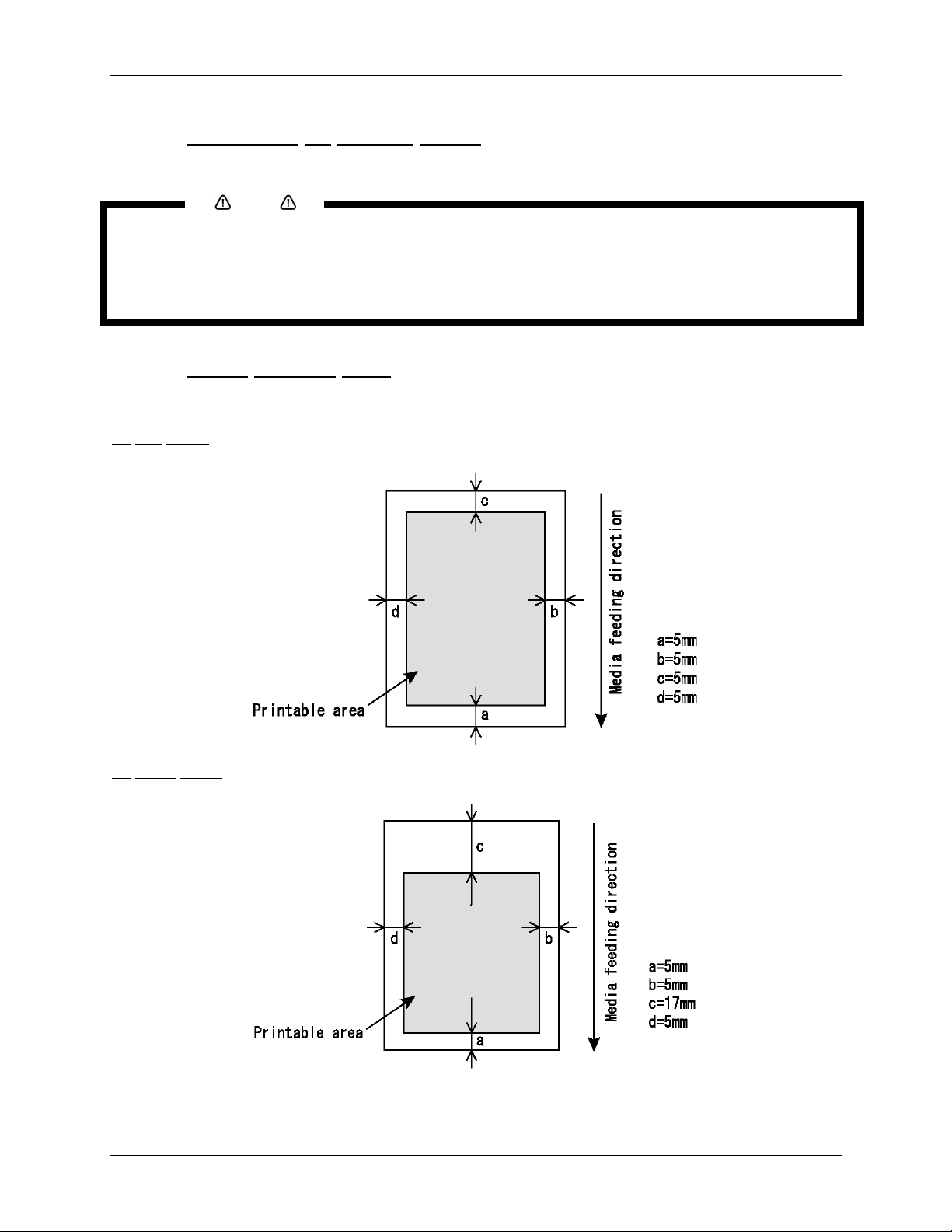
4.2.4 Media Printing Area
The printing area is shown below.
Roll media
(1)
(2)
Sheet media
38 8265/8290/8365/8390 User Guide
Page 45

4 Printer Operation
4.3 MENU OVERVIEW
This section describes how to set the Menu settings on the operation panel, and setup items.
Follow the steps below to set the Menu settings.
Step 1 : Make sure that the operation panel is normal.
Step 2 : Press the [MENU ▲] or [MENU ▼] key.
I) The screen shows following Menu.
8265/8290/8365/8390 User Guide 39
*SetupMenu*
VersionCheck Area
(7/7)
Page 46

4 Printer Operation
Notes
The Network Settings menu is displayed if the network interface board has been installed on the product.
The items on the File Management menu are displayed if a hard disk has been installed in the product.
Setup items Parameters Description
Displays the information (ink status) for each ink cassette
installed in the ink cassette slot.
SetupMenu (1/7)
InkStatus
OriginSet Sets the printing start position (origin) for printing data.
TestPrint Performs test printing.
MediaSet Makes various media settings.
Print mode setting Makes various print mode settings.
Command setting Makes various printer command settings.
SetupMenu (2/7)
Layout setting Makes various layout function settings.
Function setting Makes various processing printing data settings.
Roll setting Makes various roll media settings.
SetupMenu (3/7)
Centronics setting Sets Centronics Interface communication mode.
Network setting Makes the settings for the network interface.
Utility setting Makes various advanced function settings.
Makes various settings for the processing method of the
printing data sent from computer to the installed hard disk in
the printer.
SetupMenu (4/7)
File management
setting
Initialize setting Returns the parameters to factory default value.
Data dump For Authorized Xerox Service Technicians only
SetupMenu (5/7)
Ink Manager
Manages the ink configuration, smart chip management
system and other ink related settings.
Head Unlock The cutting blade is replaced.
Wiper clean Clean the wiper.
SetupMenu (6/7)
Tank change Tank is replaced.
Tubing Flush Makes various tubing flush settings
SetupMenu (7/7) Version Check Ability to view the installed firmware version.
SetupMenu (1/7-7/7) -
Notes
[CANCEL] key: Cancel the setup menu, and shift to the
normal condition.
By using the software server RIP (option), some setups for printing can be set by the RIP. For details, refer
to the operation manual of the products.
40 8265/8290/8365/8390 User Guide
Page 47

4.3.1 Setup Menu 1/7
4 Printer Operation
4.3.1.1 InkStatus
Menu
Depending on the mode the printer is in (cassette or printer mode), this menu will be displayed as
InkStatus. The InkStatus
menu gives all information regarding the 8 ink cassettes in the slots.
*InkStatus*
K: Y: C:
M: M: C:
Y: K: UltraE
*InkStatus*
K: C: W:
W: Y: M:
C: M: MS
8265/8290 8365/8390
Setup items Parameters Description
InkStatus
Ink status for the ink
cassette slots 1 – 8.
• Display
¾ Line 2: ink cassette slots 1 – 3
¾ Line 3: ink cassette slots 4 – 6
¾ Line 4: ink cassette slots 7 – 8
• Symbols : (Parameter 1 : Parameter 2 Parameter 3)
Param. 1 Ink Colour :
Values
:
K : Black, C : Cyan, M : Magenta, Y : Yellow, c :
Light Cyan, m : Light Magenta, W = Cleaning
Liquid
Param. 2 Ink Remaining :
Values :
= 25%
• Mode : Indicated on the lower right corner
Values
:
UltraE = Eco-Solvent / 8265/8290
MS = Mild Solvent / 8365/8390
- [CANCEL] key: shifts to the previous menu.
Notes
Refer to Setup menu
To display the Ink Status menu, be sure to use the recommended ink cassettes. If any other ink cassette is
used, the ink status will not be correctly displayed.
8265/8290/8365/8390 User Guide 41
Page 48

4 Printer Operation
4.3.1.2 OriginSet Menu
Set the printing start position (origin) for printing data. Set this when you want to re-print to blank area of
the printed media by changing the layout of the printing data.
Setup items Parameters Description
OriginSet
• L: Media feed value
• W: Print head movement
value
(Unit: mm)
Changes the print head position and media feed
amount by operating the following keys.
• [F1] key: Feeds media forward.
• [F2] key: Moves the print head to the left.
• [F3] key: Feeds media backward.
• [F4] key: Moves the print head to the right.
• [ENTER] key: Determines the setup values then
returns to the previous hierarchical menu.
- [CANCEL] key: shifts to the previous hierarchy menu.
Refer to ‘Setup menu’
Notes
When printing data from the hard disk, the printing will start from the same start position as when the
printing data was written, regardless of the home position setting value.
42 8265/8290/8365/8390 User Guide
Page 49

4 Printer Operation
4.3.1.3 TestPrint menu
*TestPrint*
*TestPrint*
Setup NozzleCheck
Setup NozzleCheck
Adj.Uni-D Adj.Bi-D
Adj.Uni-D Adj.Bi-D
(1/2)
(1/2)
*TestPrint*
Palette Maintenance
Dist.Check
(2/2)
Setup items Parameters Description
TestPrint (1/2)
Setup Performs setup printing.
NozzleCheck Performs nozzle check printing.
Adj. Uni-D Performs accuracy adjustment printing in one direction.
Adj. Bi-D Performs accuracy adjustment printing in two directions.
TestPrint (2/2)
Palette Performs palette printing.
Maintenance Maintenance status printing is performed.
Dist.Check Adjusts the Step or Feed distance of the inkjet printer (refer to
Adjustment 8.1).
TestPrint (1/2-2/2) [CANCEL] key: shift to the previous hierarchy menu.
4.3.1.4 MediaSet
Menu
*MediaSet*
Media SheetSize
Topfeed Mediacut
(1/1)
Setup items Parameters Description
MediaSet
Media Sets the media type used for test printing.
SheetSize To set the method for detecting the size of the media when sheet
media has been loaded.
Topfeed Sets the amount of media to be fed when printing begins. Make this
setting when using roll media.
Mediacut The method of cutting the media after printing is set here.
[CANCEL] key: to shift to the previous hierarchy menu.
8265/8290/8365/8390 User Guide 43
Page 50

4 Printer Operation
4.3.1.5 Media Menu
Set media type for printing.
Setup items Parameters Description
Media (1/2)
User media 1
User media 2
User media 3
To set the type of media used for printing. For setup values of
printing operation, eight settings of "user media 1-8" can be set.
User media 4
Media (2/2)
User media 5
User media 6
User media 7
User media 8
Media (1/2-2/2) - [CANCEL] key: to shift to the previous hierarchy menu.
44 8265/8290/8365/8390 User Guide
Page 51

4 Printer Operation
4.3.1.6 User Menu
Make various settings on user defined media. In the User media menu, for each setup value of following
printing operation, eight settings of "user media 1-8" can be set.
Notes
When media other than the recommended media are used (user media), the following problems may occur:
Media detection error
Oblique, torn, and creased media
Media jams
Decrease in print quality due to blurring, missing, or smudging of ink
End detection error of roll media
Problems caused by using media other than the recommended will void the warranty.
For more information, contact your local XEROX dealer.
*User1*
Heater Fixer
PostFixer Drier
(2/3)
Setup items Parameters Description
User 1-8 (1/3)
InkDryTime In order to let the ink for the printing dry, the time between the end
of the print and the beginning of the next print is set.
H.Height Sets the distance (head height) between the print head and the
media.
Stiffness Makes the setting on the stiffness of the media to be used.
Thickness Makes the setting on the thickness of the media to be used.
User 1-8 (2/3)
Heater Sets the temperature of the Heater.
Fixer Sets the temperature of the Fixer.
PostFixer Sets the temperature of the PostFixer.
Drier Sets the temperature of the Drier.
HStatus Checks the temperature of heating elements. User 1-8 (3/3)
Dist.Adj Performs various settings for media feed compensation.
User 1-8 (1/3-3/3) - [CANCEL] key: to shift to the previous hierarchy menu.
8265/8290/8365/8390 User Guide 45
Page 52

4 Printer Operation
4.3.1.7 InkDryTime Menu
Set the waiting period between the end of operation and the start of next printing in order to let the printed
media dry.
Setup items Parameters Description
InkDryTime 0 to <30 sec. > to 270 sec. to 60 min. To change the InkDryTime by operating the
following keys.
• [F2] key: to increase the setup value.
• [F4] key: to decrease the setup value.
• [ENTER] key: to confirm the setup value
• [CANCEL] key: to cancel the setup value
4.3.1.8 H.
Height Menu
Set the distance (head height) between the print head and the media. Head height can be changed to
three levels according to media thickness.
Setup items Parameters Description
HeadHeight
low When using media with a thickness of 80µm to 300µm
middle When using media with a thickness of 300µm to 700µm
Hhgh When using media with a thickness of 700µm to 1000µm
- (1 µm = 0,001 mm)
Notes
Set the height of the head in relation to the thickness of the media.
If the setting is set to "High" and the print is created on thin media, good quality print results will not be
achieved.
If the setting is set to "Low" and thick media is used, the media and print head will come into contact
and may result in damage to the product.
46 8265/8290/8365/8390 User Guide
Page 53

4.3.1.9 Stiffness Menu
Set the media sticking force (media stiffness) to the media guide.
4 Printer Operation
Setup items Parameters Description
Stiffness
Soft Setting for soft media where media feeding errors
and media jams occur.
Normal Setting for normal media.
- After setting, shift to the previous hierarchy menu.
4.3.1.10 Thickness
Menu
Set the media thickness.
Setup items Parameters Description
Thickness 50µm-<100µm>1500µm Change media thickness by operating the following keys.
• [F2] key: to increase the setup value.
• [F4] key: to decrease the setup value.
• [ENTER] key: to confirm the setup value
• [CANCEL] key: to cancel the setup value
Bidirectional quality can only be obtained when media thickness is set correctly
Notes
4.3.1.11 Heater
(A) Menu
Set the temperature of the Heater.
Setup items Parameters Description
Heater (A) OFF – 50°C Change heater temperature by operating the following
keys.
• [F2] key: to increase the setup value.
• [F4] key: to decrease the setup value.
• [ENTER] key: to confirm the setup value
• [CANCEL] key: to cancel the setup value
8265/8290/8365/8390 User Guide 47
Page 54

4 Printer Operation
Notes
The default setting for the heater is set to ‘50°C’.
The function of the heater (A): Warming the transfer paper before entering the pressure rollers. The
pre-expansion helps to minimize media cockling.
4.3.1.12 Fixer
(B) Menu
Set the temperature of the Fixer.
Setup items Parameters Description
Fixer (B) OFF – 40°C Change fixer temperature by operating the following keys.
• [F2] key: to increase the setup value.
• [F4] key: to decrease the setup value.
• [ENTER] key: to confirm the setup value
• [CANCEL] key: to cancel the setup value
4.3.1.13 Post
Fixer (C) Menu
Set the temperature of the Post Fixer.
*Post Fixer (C)*
OFF - 70ºC +
50ºC -
F2, F4 > ENTER
Setup items Parameters Description
Post Fixer (C) OFF – 50°C Change post fixer temperature by operating the following keys.
• [F2] key: to increase the setup value.
• [F4] key: to decrease the setup value.
• [ENTER] key: to confirm the setup value
• [CANCEL] key: to cancel the setup value
48 8265/8290/8365/8390 User Guide
Page 55

4.3.1.14 Drier (D) Menu
Set the temperature of the Drier.
4 Printer Operation
Setup items Parameters Description
Drier OFF – 50°C Change drier temperature by operating the following keys.
• [F2] key: to increase the setup value.
• [F4] key: to decrease the setup value.
• [ENTER] key: to confirm the setup value
• [CANCEL] key: to cancel the setup value
Notes
The default setting for the drier is set to ‘50°C’.
The function of the drier (D): Heating the printed transfer paper evaporates the water fast enough so
that the print is touch-dry when wound.
4.3.1.15 HStatus
Menu
Check the temperature of the heating elements.
Notes
A stands for the Heater.
B stands for the Fixer.
C stands for the Post Fixer.
D stands for the Dryer.
Press the [CANCEL] key to go to the previous menu.
8265/8290/8365/8390 User Guide 49
Page 56

4 Printer Operation
4.3.1.16 Dist. Adj Menu
To perform various settings for media feed compensation
For details of the distance adjustment, refer to "Distance adjustment".
Notes
Setup items Parameters Description
Dist.Adj
Print1 Performs printing by media feed compensation. A correction pattern with
a width of ± 0.20% (in steps of 0.10 %) is printed around the centre of the
correction value currently set.
Change Changes the media feed compensation value.
The menu changes to the Change Media Feed Correction Value menu.
Print2 Performs printing by media feed compensation (for fine adjustment). A
correction pattern with a width of ± 0.02% (in steps of 0.01%) is printed
around the centre of the correction value currently set.
- [CANCEL] key: Shifts to the previous hierarchy menu.
4.3.1.17 Change menu
Change the distance adjustment value.
Setup items Parameters Description
Change 90.00%-<100.00%>-110.00% Changes the media feed compensation value by
operating the following keys.
• [F2] key: to increase the setup value.
• [F4] key: to decrease the setup value.
• [ENTER] key: to confirm the setup value
• [CANCEL] key: to cancel the setup value
50 8265/8290/8365/8390 User Guide
Page 57

4.3.1.18 Dist.Adj Menu
Indicates that the Distance Adjustment test print is printing.
4 Printer Operation
Setup items Parameters Description
Dist.Adj
Data printing Now printing by media feed compensation. Wait for
a while until printing has been finished.
- • [CANCEL] key: to perform following operations :
• Media feed correction printing has been finished.
• To eject media.
• To shift to the previous hierarchy menu.
4.3.1.19 SheetSize
Menu
When loading a sheet of media, set the method for detecting the size of the media.
*SheetSize*
Auto Length
Width
-Length- (1/1)
Setup items Parameters Description
SheetSize
<Auto> The length and width of the sheet media is automatically detected.
Length When placing normal size sheet media vertically on the tray.
Width When placing normal size sheet media horizontally on the tray.
- After setting, shift to the previous hierarchy menu.
Notes
When using sheet media other than recommended media, set to "blank form vertical" or "blank form
horizontal".
The following size of sheet media can be set.
o ISO series (A0, A1, A2, A3, A4)
o JIS series (B1, B2, B3, B4)
o ARCH series (A, B, C, D)
8265/8290/8365/8390 User Guide 51
Page 58

4 Printer Operation
4.3.1.20 TopFeed Menu
Set the amount of media to be fed when printing begins. Make this setting when using roll media.
Setup items Parameters Description
TopFeed <0mm>-400mm To feed media at the start of printing. Set when
printing on roll media.
• [F2] key: to increase the setup value.
• [F4] key: to decrease the setup value.
• [ENTER] key: to confirm the setup value
• [CANCEL] key: to cancel the setup value
4.3.1.21 MediaCut
Menu
Set media cut method after printing.
Setup items Parameters Description
Media cutting
Auto After printing has been completed, the media is sent to the media cut
position and is automatically cut.
Manual Feed media to the media cut position after printing.
Use regular cutting blades available from hardware stores.
Off No media feed after printing.
- When "Auto" is selected, proceed to the Shortest Cut Length menu.
• If "Manual" or "Off" has been selected, the screen changes to the menu
of the previous hierarchy.
Notes
For the situations shown below, the media cut settings are always changed to "Off" regardless the
previous settings.
o When "Take-up system" or “Roll-up/roll off system” is set for the media detection settings (Media
detection menu)
When using the media shown below, set the media cut setting to "Manual". If set to "Auto", the
following errors may occur :
o Cloth material: The cloth fibre is not completely cut.
o Media with glue: Glue will adhere to the cutting blade and decrease cutting performance.
52 8265/8290/8365/8390 User Guide
Page 59

4.3.2 Setup Menu 2/7
4 Printer Operation
4.3.2.1 PrintMode
To perform various settings for Printing mode.
Setup items Parameters Description
PrintMode
4.3.2.2 PrnMode
Perform various settings for Print mode. For each setup value of Print mode, four settings of "Printing
mode 1" - "Printing mode 4" can be set.
Menu
Print mode 1
Print mode 2
Print mode 3
Print mode 4
- [CANCEL] key: to shift to the previous hierarchy menu.
Menu
For each setup value of Printing mode, four settings of "Printing
mode 1" - "Printing mode 4" can be set.
Setup items Parameters Description
PrnMode 1-4 (1/2)
PrnMode 1-4 - [CANCEL] key: To shift to the previous hierarchy menu.
8265/8290/8365/8390 User Guide 53
Printing condition To set printing quality.
Printing direction To set print head moving direction for printing.
Repeat printing To make settings for the repeat print.
Head speed To set the head speed
Weaving To set which weaving pattern should be used for printing PrnMode 1-4 (2/2)
ScanWidth To specify the carriage movement
Page 60

4 Printer Operation
4.3.2.3 Condition Menu
Select the required printing quality.
*Condition*
540x720 720x720
1080x1080 1440x720
-360x360- (2/5)
*Condition*
720x1440 Diag1440
1440x1440 2160x1080
-360x360- (3/5)
*Condition*
1080x2160 Diag2160
2880x1440 1440x2880
-360x360- (4/5)
*Condition*
Diag2880
-360x360- (5/5)
Setup items Parameters Description
Condition (1/5)
360 × 360dpi
720 × 360dpi
The display changes to interlace setup items after the print
quality items settings have been finished.
360 × 720dpi
Diag720dpi
Condition (2/5)
540x720dpi
720x720dpi
1080x1080dpi
1440x720dpi
Condition (3/5)
720x1440dpi
Diag1440 dpi
1440x1440dpi
2160x1080dpi
Condition (4/5)
1080x2160dpi
Diag2160dpi
2880x1440dpi
1440x2880dpi
Condition (5/5) Diag2880dpi
Condition (1/5 – 5/5) - [CANCEL] key: To shift to the previous hierarchy menu.
54 8265/8290/8365/8390 User Guide
Page 61

4.3.2.4 Direction Menu
Set print head moving direction for printing.
4 Printer Operation
Setup items Parameters Description
Direction
UniDir. Prints in one direction.
BiDir. Prints bi-directionally.
- [CANCEL] key: To shift to the previous hierarchy menu.
4.3.2.5 RepeatPrn Menu
Make settings for the repeat print.
Setup items Parameters Description
RepeatPrn
Count To set the number of repeats per line of printing.
IntervalTime To set interval time for the repeat print.
- [CANCEL] key: To shift to the previous hierarchy menu.
4.3.2.6 Count Menu
Set the number of repeats per line of printing.
Setup items Parameters Description
Count <Once> to 99 times To change repeat times by operating the following keys:
• [F2] key: to increase the setup value.
• [F4] key: to decrease the setup value.
• [ENTER] key: to confirm the setup value
• [CANCEL] key: to cancel the setup value
8265/8290/8365/8390 User Guide 55
Page 62

4 Printer Operation
4.3.2.7 IntervalTime Menu
Set interval time for the repeat print.
Setup items Parameters Description
IntervalTime <0.0 sec.> to 0.1 to 5.0 sec. To change interval time by operating the following keys.
• [F2] key: to increase the setup value.
• [F4] key: to decrease the setup value.
• [ENTER] key: to confirm the setup value
• [CANCEL] key: to cancel the setup value
4.3.2.8 HeadSpeed Menu
Only applicable when printing in 360dpi.
Setup items Parameters Description
HeadSpeed
Normal Print at normal speed of 360 dpi
Fine Print at the speed of 720 dpi (slower – more drying time)
- [CANCEL] key: To shift to the previous hierarchy menu.
56 8265/8290/8365/8390 User Guide
Page 63

4.3.2.9 Weaving Menu
4 Printer Operation
Without weaving ON, an image is completed (formed) by printing a series of
complementary rectangular shaped stripes (bands, swaths, passes). Inherent to
classic inkjet printing is that ink drying effects, stepping mismatch, miss firing
nozzles show up in the printed image via ink bleeding and various types of
banding. By switching ON one of the weave patterns you will give the traditional
rectangular print swaths a wave-shaped look that will save you time and boost
your output quality. Difficult images will print smoother, banding will be
suppressed (neutralized) and you will have to spend less time fine-tuning your
printer to create great looking output.
Moreover, when using wave-tuned profiles, you will be able to boost your printer’s
colour gamut as the i² (intelligent interweaving) technology allows depositing
more ink, helping you to achieve higher colour densities.
Setup items Parameters Description
Sign / Quality Weaving (1/2)
Weaving (2/2)
Picture / Speed
Stitch
Classic
Please refer to the table below to know what the different weaving
forms are and which one to use.
Off
Weaving (1/2 – 2/2) - [CANCEL] key: To shift to the previous hierarchy menu.
8265/8290/8365/8390 User Guide 57
Page 64

4 Printer Operation
Weaving
method
Sign / Quality
Picture / Speed
Stitch
Classic
Off
User Tip Print Modes
Supported
Preferred setting
for signage/poster
applications
containing big
areas with solid
colours or critical
gradients and for
photo quality
output on coated
media.
(small loss of
speed in 2 pass
modes)
Preferred setting
for non-sign
images, pictures,
continuous tone
data.
(no speed loss)
Creates a fine print
swath overlap.
Mildly improves
print quality versus
“Off” setting.
(lowest level of
interweaving)
Use classic to
maintain classic
printer behaviour in
all print modes.
(prior to firmware
version 3.01)
Switches off any
kind of
overlap/weaving.
Useful when trying
to inspect
individual nozzle
behaviour or
checking the step-
adjust.
720x720
540x720
Default selection after
firmware installation
720x720
540x720
(*) 4-pass is a quality
mode and will always
use a tuned sign weave
pattern, even if picture is
selected from the panel /
720x720
540x720
(*) 4 pass data will be
printed as classic
All print modes
All print modes
RIP.
2 pass
4 pass
2 pass
4 pass
2 pass
4 pass
2 pass
4 pass
2 pass
4 pass
2 pass
4 pass
2 pass 4 pass
58 8265/8290/8365/8390 User Guide
Page 65

4 Printer Operation
4.3.2.10 ScanWidth Menu
It is possible to specify the carriage movement along the media – printed area. This will have a direct
effect on the drying time!! Please find more details below.
Setup items Parameters Description Drying time
ScanWidth
DataWidth Carriage moves only over the printing area Short
MediaWidth Carriage moves over the media Depending on MediaWidth
FullWidth Carriage moves over the full width Long
4.3.2.11 Command
Menu
Perform various settings for printer commands.
Setup items Parameters Description
Command (1/2)
Step To set the units for amount of movement for printing.
Resolu. Makes settings for image resolution while printing with image data.
OnlineTimer Makes settings for the time between the end of receiving printing
data from a computer and recognizing the end of printing data.
- [CANCEL] key: to shift to the previous hierarchy menu.
8265/8290/8365/8390 User Guide 59
Page 66

4 Printer Operation
4.3.2.12 Step Menu
Set the units for amount of movement for printing.
Setup items Parameters Description
Step
<0.010mm> To set the printing units to 0.010mm.
<0.025mm> To set the printing units to 0.025mm.
- To shift to the previous hierarchy menu.
Notes
Please note that some software packages use the “step per mm” terminology, in which case a program step
of 0.025 mm corresponds with 40 steps per mm and a program step of 0.010 mm with 100 steps per mm.
4.3.2.13 Resolu.
Mmenu
Set resolution for image data for printing.
Setup items Parameters Description
Resolu. (1/2)
360dpi
Makes settings for image resolution while printing with image data.
600dpi
720dpi
1080dpi
Resolu. (2/2)
1200dpi
1440dpi
2160dpi
2880dpi
Resolu. (1/2-2/2) - To shift to the previous hierarchy menu.
60 8265/8290/8365/8390 User Guide
Page 67

4 Printer Operation
4.3.2.14 OnlineTimer Menu
Set time from the moment of receiving termination of printing data sent by computer to the recognition of
end of printing data.
Setup items Parameters Description
OnlineTimer OFF/2sec. - <30sec.> -
800sec.
To change the Online time out time by operating
the following keys.
• [F2] key: to increase the setup value.
• [F4] key: to decrease the setup value.
• [ENTER] key: to confirm the setup value
• [CANCEL] key: to cancel the setup value
4.3.2.15 Layout
Menu
Make various settings on layout function.
Notes
The layout function automatically determines the size of printing data sent from the computer, and then
determines the amount of roll media required without wasting media.
If sheet media has been loaded, the layout function is disabled.
Setup items Parameters Description
Layout
Joint Makes settings for stitching print.
CtPos To set the media cutting position after printing has been completed.
- [CANCEL] key: To shift to the previous hierarchy menu.
4.3.2.16 Joint
Menu
Set joint printing.
Setup items Parameters Description
Joint
<Off> Does not perform stitching print.
On Performs stitching print
- - Shifts to the previous hierarchy menu.
8265/8290/8365/8390 User Guide 61
Page 68

4 Printer Operation
4.3.2.17 CutPos. Menu
Set the media cutting position after printing has been finished.
Setup items Parameters Description
CutPos.
Standard To cut the media to fit the media width, so that it meets the regulated size.
<Data> To cut the media according to the size of the printing data.
- - Shifts to the previous hierarchy menu.
4.3.2.18 Function
Menu
Perform various settings for processing of printing data.
*Function*
CNY->K
(1/1)
Setup items Parameters Description
Function
CMYÆK Makes settings for printing method to present black.
Scale Sets the enlargement and reduction ratios for printing data.
Mirror To draw reversed printing data.
- • [CANCEL] key: Shifts to the previous hierarchy menu.
4.3.2.19 CMY
Æ K Menu
Replace CMY values with K (black)
Setup items Parameters Description
CMYÆK
<No> • If MH-GL, GL2 are set on the Command Settings menu, be sure to use
CMY (mixed colours) ink.
• If RTL-PASS is set, use both CMY (mixed colours) ink and K (black)
ink.
Yes Always use K (black) ink.
- To shift to the previous hierarchy menu.
62 8265/8290/8365/8390 User Guide
Page 69

4.3.3 Setup Menu 3/7
4 Printer Operation
4.3.3.1 RollSetup
Perform various settings for roll media.
Setup items Parameters Description
RollSetup
Menu
Disable Set this when roll media setup is not used.
Roll1
Roll2
Roll3
- • [CANCEL] key: To shift to the previous hierarchy menu.
For each setup value of roll media, 3 settings of "Roll media 1" - "Roll
media 3" can be set.
8265/8290/8365/8390 User Guide 63
Page 70

4 Printer Operation
4.3.3.2 Roll Menu
Set media roll length.
Setup items Parameters Description
Roll 1-4 1 m to <30 m>to 99 m To change roll media length by operating the
following keys.
• [F2] key: to increase the setup value.
• [F4] key: to decrease the setup value.
• [ENTER] key: to confirm the setup value
• [CANCEL] key: to cancel the setup value
4.3.3.3 Centro.
Menu
Set communication mode to Centronics interface.
Setup items Parameters Description
Centro.
Centro. To set communication mode to Centronics mode.
.Bi Centro. To set communication mode to Bi-Centronics mode.
- To shift to the previous hierarchy menu.
64 8265/8290/8365/8390 User Guide
Page 71

4 Printer Operation
4.3.3.4 Network Menu
Make the settings for the network interface.
Notes
The Network Settings menu is displayed if the network interface board has been installed.
Be sure to consult the network administrator before making the settings in the Network Settings menu.
Setup items Parameters Description
Network (1/1)
IPaddress To set the IP address of the product.
SubnetMask To set the subnet mask of the product.
Gateway To set the IP address of the connected gateway.
Network - • [CANCEL] key: To shift to the previous hierarchy menu.
4.3.3.5 IPaddress
Menu
Set the IP address of the product.
Setup items Parameters Description
IPaddress <000.000.000.000>-
223.255.255.254
Use the following keys to change the IP address.
• [F1] key: Moves one digit to the left on the setting value to be changed.
• [F2] key: Increases the setting value.
• [F3] key: Moves to the right on the setting value.
• [F4] key: Reduces the setting value.
• [ENTER] key: to confirm the setup value
• [CANCEL] key: to cancel the setup value
8265/8290/8365/8390 User Guide 65
Page 72

4 Printer Operation
4.3.3.6 SubnetMask Menu
Set the subnet mask of the product.
Setup items Parameters Description
SubnetMask 000.000.000.000
<255.255.255.000>
255.255.255.255
Use the following keys to change the Subnet Mask.
• [F1] key: Moves one digit to the left on the setting value to be changed.
• [F2] key: Increases the setting value.
• [F3] key: Moves to the right on the setting value.
• [F4] key: Reduces the setting value.
• [ENTER] key: Sets the setting value, and moves the screen to the
menu of the previous hierarchy.
• [CANCEL] key: Cancels the setting value, and moves the screen to the
menu of the previous hierarchy.
Refer to ‘Network setting menu’
4.3.3.7 Gateway
Menu
The product sets the IP address of the connected gateway.
Setup items Parameters Description
Gateway <000.000.000.000> -
223.255.255.254
Use the following keys to change the IP address.
• [F1] key: Moves one digit to the left on the setting value to be changed.
• [F2] key: Increases the setting value.
• [F3] key: Moves to the right on the setting value.
• [F4] key: Reduces the setting value.
• [ENTER] key: to confirm the setup value
• [CANCEL] key: to cancel the setup value
66 8265/8290/8365/8390 User Guide
Page 73

4.3.4 Setup Menu 4/7
4 Printer Operation
4.3.4.1 Utility
menu
Perform various settings for application functions of products.
*Utility*
ErrorDisp. MediaDet.
OnCleaning MediaWidth
(1/3
)
*Utility*
SlantCh. RemPanel
(3/3)
Setup items Parameters Description
Utility (1/3)
ErrorDisplay To set display method to the operation panel when minor error
occurred.
MediaDet. When media has been initialized, to perform detection of width
and front edge of the media.
OnCleaning Cleaning should be performed automatically when the power is
turned on.
MediaWidth If media detection is not performed for initial media, to set the
width of the media in the tray.
Utility (2/3)
Prn+Wipe To wipe while printing, to take care of possible condensation
on the print head nozzle plate.
SmartTop The ideal temperature of the media is near to the preheater.
This area of paper is fed before a print starts to obtain perfect
quality.
AutoClean Performs cleaning cycle while printer is idle at the set
temperature.
CapCycle To perform auto tubing flush when printer is idle.
SlantCh. Whether to perform a SlantCheck or not. Utility (3/3)
RemPanel Enables Remote Panel software access.
Utility (1/3 – 3/3) - • [CANCEL] key: To shift to the previous hierarchy menu.
8265/8290/8365/8390 User Guide 67
Page 74

4 Printer Operation
4.3.4.2 ErrorDisp. Menu
To set display method to the operation panel when minor error occurred.
Setup items Parameters Description
ErrorDisp.
Off No ErrorDisplay.
On To perform ErrorDisplay.
- To shift to the previous hierarchy menu.
4.3.4.3 PaperDet. Menu
To perform detection of width and edge of the media, when media has been initialized
Setup items Parameters Description
PaperDet.
Normal To perform media detection automatically.
OFF No media detection.
TakeUpRoll Should be selected when using the winding system and media is
most right loaded.
RollFeed Should be selected when using the winding system and media is
centre loaded
- • [CANCEL] key: to shift to the previous hierarchy menu.
Notes
The default setting is ‘RollFeed’ as a result of the standard unwinder / winder 100 with your unit.
When setting "Take-up Mechanism" on the Media Detection menu, the following limits are applied to
the operation of the product.
o For initial media, only the media width is detected.
o Under normal conditions, media cannot be sent backward.
o The media cannot be moved forward or backward from the Origin Setting menu.
o The settings in the Media Cut menu are disabled, and the settings are changed to "Off". (Refer to
‘Media cut menu’)
68 8265/8290/8365/8390 User Guide
Page 75

4.3.4.4 OnCleaning Menu
Set when cleaning should be performed automatically when the power is turned on.
4 Printer Operation
Setup items Parameters Description
OnCleaning
<Off> Power on cleaning is not performed.
Little
Normal
Power on cleaning is performed.
Powerful
- To shift to the previous hierarchy menu.
4.3.4.5 MediaWidth
Menu
If media detection has not been performed during initialization, the width of the media is set here.
It can be set in the following ranges: 90” model: 210mm-2240mm
Notes
On the media width menu,
If a value larger than the width of the media has been set, media or the product may be contaminated
by the ink during printing.
If a value smaller than the width of the set media has been set, media may not be cut correctly.
*MediaWidth*
210mm-2290mm +
841mm F2, F4 > ENTER
Setup items Parameters Description
MediaWidth 210mm - <841mm> -
2240mm
To change media width by operating the following keys.
• [F2] key: to increase the setup value.
• [F4] key: to decrease the setup value.
• [ENTER] key: to confirm the setup value
• [CANCEL] key: to cancel the setup value
8265/8290/8365/8390 User Guide 69
Page 76

4 Printer Operation
4.3.4.6 Prn+Wipe Menu
To take care of possible condensation on the head nozzle plate, it is possible to wipe while printing.
Setup items Parameters Description
Prn+Wipe
OFF No wiping during printing
High After printing 10 passes, wiping cycle will be performed.
Middle After printing 16 passes, wiping cycle will be performed.
Low After printing 22 passes, wiping cycle will be performed.
- • [CANCEL] key: To shift to the previous hierarchy menu.
4.3.4.7 SmartTop
Menu
This feature will take care of a feed of 5 centimetres before every print. To start printing on media which is
pre heated. This function will only be visible when the B heater is activated.
Setup items Parameters Description
Off No media feed of 5 centimetres SmartTop
ON A media feed of 5 centimetres
- • [CANCEL] key: to shift to the previous hierarchy menu.
4.3.4.8 AutoClean
Menu
Printer performs an automatic cleaning before or during printing. Or during an idle period of 1 hour of
more.
Setup items Parameters Description
AutoClean
Waiting To perform a little, normal, powerful cleaning while printer is
idle for 1, 2, 3, 4, 5, 6, 9, 12, 18, 24 hours.
Printing To perform a little, normal, powerful cleaning after 5, 10, 15,
20, 30, 45, 60, 90, 120, 150,180 minutes of printing.
Before Printing To perform a little, normal, powerful a cleaning before every
job
- • [CANCEL] key: to shift to the previous hierarchy menu.
70 8265/8290/8365/8390 User Guide
Page 77

4 Printer Operation
4.3.4.9 CapCycle Menu
Perform a TubingFlush every 1 to 24 hours.
A TubingFlush is automatically performed after 10 minutes of idle and before shut down of the printer.
Notes
Setup items Parameters Description
OFF No tubing flush will be performed CapCycle
1 – 6 - 24 hours Every 1 – 24 hours (adjustable) a TubingFlush is performed.
- • [CANCEL] key: To shift to the previous hierarchy menu.
4.3.4.10 SlantCh.
Menu
To enable or disable whether the printer performs a slant check after every print of at least 1 meter.
Setup items Parameters Description
Off No SlantCheck SlantCh.
On Perform SlantCheck
- • [CANCEL] key: To shift to the previous hierarchy menu.
4.3.4.11 RemPanel
Menu
Enables or disables using Remote Panel software.
*RemPanel*
Off On
-On- (1/1)
Setup items Parameters Description
Off Remote panel usage is disabled. RemPanel.
On Remote panel usage is enabled.
- • [CANCEL] key: To shift to the previous hierarchy menu.
8265/8290/8365/8390 User Guide 71
Page 78

4 Printer Operation
4.3.4.12 Initial. Menu
Return parameters to the factory settings.
*Initial*
Network Utility
(3/3)
Setup items Parameters Description
Initial. (1/3)
All Returns all parameters to the factory setting.
MediaSet Returns parameters in the media setup menu to the factory setting.
PrintMode Returns parameters in the print mode menu to the factory setting.
Command Returns parameters in the command setup menu to the factory setting.
Initial. (2/3)
Layout Returns parameters in the layout setup menu to the factory setting.
Function Returns parameters in the function setup menu to the factory setting.
RollSetup Returns parameters in the roll media setup menu to the factory setting.
Centro Returns parameters in the Centronics setup menu to the factory setting.
Network Returns parameters in the network setup menu to the factory setting. Initial. (3/3)
Utility Returns parameters in the utility setup menu to the factory setting.
Initial. (1/3-3/3) - • [CANCEL] key: Shifts to the previous hierarchy menu.
4.3.4.13 All
Menu
All setup values are set to the factory default settings.
Setup items Parameters Description
All
NO No initialization.
OK To perform initialization.
- After setting, to shift to the previous hierarchy
menu.
72 8265/8290/8365/8390 User Guide
Page 79

4.3.4.14 MediaSet Menu
Setup values of Media setup menu are set to the factory default settings.
4 Printer Operation
Setup items Parameters Description
MediaSet
<NO> No initialization.
OK To perform initialization.
- After setting, to shift to the previous hierarchy menu.
4.3.4.15 PrintMode
Menu
Setup values of Printing mode menu are set to the factory default settings.
Setup items Parameters Description
PrintMode
<NO> No initialization.
OK To perform initialization.
- After setting, to shift to the previous hierarchy
menu.
4.3.4.16 Command
Menu
Setup values of Command Setup menu are set to the factory default settings.
Setup items Parameters Description
Command
<NO> No initialization.
OK To perform initialization.
- After setting, to shift to the previous hierarchy
menu.
8265/8290/8365/8390 User Guide 73
Page 80
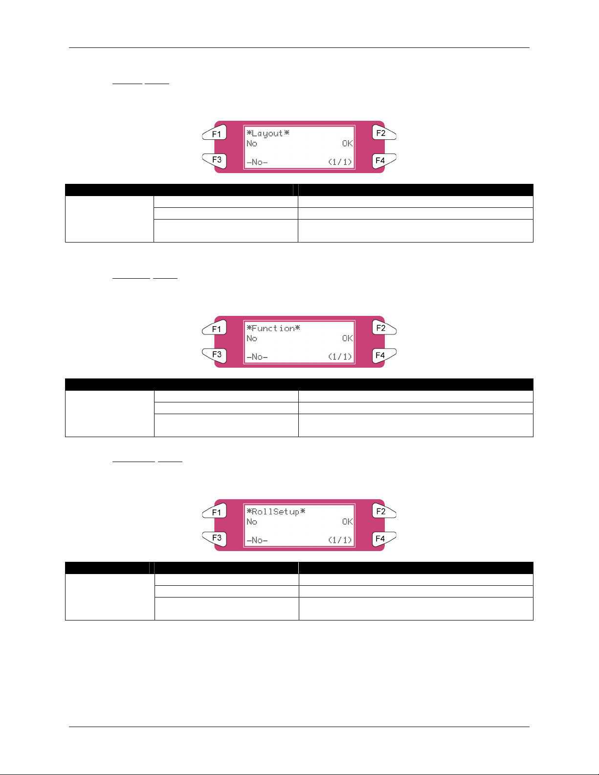
4 Printer Operation
4.3.4.17 Layout Menu
Setup values of Layout Setup menu are set to the factory default settings.
Setup items Parameters Description
Layout
<NO> No initialization.
OK To perform initialization.
- After setting, to shift to the previous hierarchy
menu.
4.3.4.18 Function
Menu
Setup values of Function setup menu are set to the factory default settings.
Setup items Parameters Description
Function
<NO> No initialization.
OK To perform initialization.
- After setting, to shift to the previous hierarchy
menu.
4.3.4.19 RollSetup
Menu
Setup values of Roll Media setup menu are set to the factory default settings.
Setup items Parameters Description
RollSetup
<NO> No initialization.
OK To perform initialization.
- After setting, to shift to the previous hierarchy
menu.
74 8265/8290/8365/8390 User Guide
Page 81

4.3.4.20 Centro. Menu
Setup values of Centronics menu are set to the factory default settings.
4 Printer Operation
Setup items Parameters Description
Centro.
<NO> No initialization.
OK To perform initialization.
- After setting, to shift to the previous hierarchy
menu.
4.3.4.21 Network
Menu
Setup values of Network menu are set to the factory default settings.
Setup items Parameters Description
Network
<NO> No initialization.
OK To perform initialization.
- After setting, to shift to the previous hierarchy
menu.
4.3.4.22 Utility
Menu
Setup values of Utility menu are set to the factory default settings.
Setup items Parameters Description
Utility
<NO> No initialization.
OK To perform initialization.
- After setting, to shift to the previous hierarchy
menu.
8265/8290/8365/8390 User Guide 75
Page 82

4 Printer Operation
4.3.5 Setup Menu 5/7
4.3.5.1 DataDump
Menu
To perform dump printing for online function check.
Parameters Description
DataDump
Start/End
Dump printing is used by service persons to check the functions of the
printer. Do not use this function for normal printing.
All
- • [CANCEL] key:
• To exit Dump Mode.
• To shift to the previous hierarchy menu.
4.3.5.2 InkManager
Menu
Notes
Setup items Parameters Description
InkManager
(1/2)
InkManager
(2/2)
Head Wash To perform a head cleaning.
Ink Load To load ink.
Ink Change
To change ink configuration (2x4 1x6)
LongStore To store your printer for a long time. (8365/8390 Only)
InkSupply To switch between the Bulk Ink System for 8365/8390 and
ink cassettes.
ChipMgr To switch between cassette and printer mode
- • [CANCEL] key: shift to the previous hierarchy menu.
76 8265/8290/8365/8390 User Guide
Page 83

4.3.5.3 HeadWash Menu
To perform a head wash to remove all ink of the ink supplying system.
4 Printer Operation
Setup items Parameters Description
HeadWash
No Do not wash the ink supplying system.
Yes To wash the ink supplying system.
- • [CANCEL] key: shift to the previous hierarchy
menu.
Only after two head wash cycles it is possible to change ink types. Use the ‘Ink Load‘ to load ink
Notes
The process consists of several cleaning loadings, several air loadings and one ink loading. On the
display of the operation panel a time indication is mentioned on the fourth line.
Message Time
1. Please remove cart.
2. Ink Discharge 7
3. Please insert Cleaning cart
4. During washing wait for a while 29
5. Remove cassettes
6. During washing wait for a while 7
7. The end
8. Ink Load 13
4.3.5.4 InkLoad
Menu
Start and stop an ink load.
Setup items Parameters Description
InkLoad
Pump 1 Load ink into head 1 and 2
Pump 2 Load ink into head 3 and 4
ALL Load ink for complete system
- • [CANCEL] key: shift to the previous hierarchy
menu.
8265/8290/8365/8390 User Guide 77
Page 84

4 Printer Operation
4.3.5.5 InkChange Menu
Change the ink configuration (from 2x4 to 1x6 or opposite).
Setup items Parameters Description
InkChange
No Do not perform an ink change.
Yes To start the ink change cycle.
- • [CANCEL] key: shift to the previous hierarchy
menu.
Notes
To reduce the consumption of ink and cleaning liquid it is recommended to change ink types by using the
‘Ink Change’ cycle.
The process consists of several cleaning loadings, several air loadings and one ink loading. On the
display of the operation panel a time indication is mentioned on the fourth line.
Message Time
1. Please remove cart. (*)
2. Ink Discharge (*) 1
3. Please insert Cleaning cart (*)
4. During washing wait for a while (*) 5
5. Remove cassettes
6. During washing wait for a while 7
7. Please insert ink cart.
8. Ink refill 13
9. The end
(*) = This will be asked 5 times.
78 8265/8290/8365/8390 User Guide
Page 85

4 Printer Operation
4.3.5.6 Longstore Menu (8365/8390 Only)
When storing the printer for longer than 5 days, ink cassettes with 8365/8390 Cleaning liquid should be
installed. For more details, please refer to maintenance cycle.
Setup items Parameters Description
Longstore
No Do not perform a long store
Yes Perform the long store procedure.
- • [CANCEL] key: shift to the previous hierarchy
menu.
The process consists of several cleaning loadings, several air loadings and one ink loading. On the
display of the operation panel a time indication is mentioned on the fourth line.
Message Time
1. Please remove cart.
2. Ink Discharge
3. Please insert Cleaning cart.
4. During washing wait for a while
29
5. Ink not filled [ALL]
6. Power OFF
Notes
When a cleaning cassettes is empty during LongStore procedure, remove the empty one and replace it by a
new one. Only the last cycle will be repeated. Although, the full time (29 minutes) is mentioned again on the
panel.
After powering OFF the machine, the tubings in the waste bottle should be mounted on the nipple plate at
the bottom of the machine. This to prevent air is coming in the ink system which will dry out the heads.
1 Nipple plate
How to load ink after a long store procedure?
8265/8290/8365/8390 User Guide 79
Page 86

4 Printer Operation
Message Time
1. Power ON without Ink Cassettes installed.
2. Insert Cartridges
13
3. Auto InkFill
Notes
When powering ON and INK cassettes are already installed, the message “Not Original Ink” will be
displayed. Remove 1 and reinsert it, then the procedure will continue.
4.3.5.7 InkSupply
menu
This setting should be enabled (ON) when using the Bulk Ink System.
Please refer to the user’s Guide of the Bulk Ink System to know how to install and use it.
Important
Setup items Parameters Description
InkSupply
Off Using ink cassettes
On Using the Bulk Ink System
- • [CANCEL] key: shifts to the previous menu.
4.3.5.8 ChipMgr
menu
Setup items Parameters Description
ChipMgr
Cassette Use the smart chips on the ink cassettes
Printer Use the smart chip manager system on the top (or
back) of the machine. Recommended when
working with a Bulk Ink System.
- • [CANCEL] key: shifts to the previous menu.
80 8265/8290/8365/8390 User Guide
Page 87

4.3.6 Setup Menu 6/7
4 Printer Operation
4.3.6.1 H.Unlock
Menu
*H.Unlock*
No Yes
(1/1)
*H.Unlock*
To lock heads press
-> ENTER
Setup items Parameters Description
H.Unlock
No Cancels unlocking the carriage.
Yes Unlocks the carriage.
- • [CANCEL] key: shifts to the previous hierarchy menu.
4.3.6.2 WiperClean
Menu
Clean the wipers.
Refer to "Cleaning the cleaning wiper" for details regarding the procedure for cleaning the cleaning wiper.
Notes
*WiperClean*
No Yes
(1/1)
*WiperClean*
Wipers Clean?
-> ENTER
Setup items Parameters Description
WiperClean
No Do not clean the cleaning wiper.
Yes To clean the cleaning wiper.
- • [CANCEL] key: shifts to the previous hierarchy menu.
8265/8290/8365/8390 User Guide 81
Page 88

4 Printer Operation
4.3.6.3 TankCng. Menu
Change the waste fluid tank. Set when changing the waste fluid tank.
Notes
Refer to "Replacing the waste liquid tank" for details regarding the procedure for changing the waste fluid
tank.
Setup items Parameters Description
TankCng.
Cancel Do not change the tank.
Enter When tank has been changed.
- • [CANCEL] key: shifts to the previous hierarchy menu.
4.3.6.4 TubingFlush
Menu
Removes rest fluids out of the capping station and waste tubes to prevent clogging.
Notes
The tubing flush sequence will not remove fluids out of the head nor out of the ink supply tubes.
Please refer to the Periodical Services for the daily and weekly maintenance of the 8265/8290/8365/8390.
The tubing flush feature includes following sequence:
1. The head is moved away from the capping position.
2. Pump sequence is started.
3. Pumps are stopped and head is re-capped.
The tubing flush can be started via the “TubingFlush” menu.
A tubing flush will also be performed before powering OFF the printer.
Notes
On the display following text appears:
*TubingFlush*
Flushing Pump 1-2
<ENTER> : END
The pumps turn for a certain time. Press ENTER as they stop. To stop the pump motors earlier, press
ENTER during the pump cycle.
82 8265/8290/8365/8390 User Guide
Page 89

4.3.7 Setup Menu 7/7
4.3.7.1 VersionCheck
Menu
Check the installed firmware and heater system version.
*SetupMenu*
VersionCheck Area
(7/7)
4 Printer Operation
Setup items Parameters Description
Version Check - • [CANCEL] key: shift to the previous hierarchy
menu.
4.3.7.2 Area
Menu
View the total area of media printed on the machine.
*Area*
Total
46.16m
2
Setup items Parameters Description
Area Total Total area of media.
- • [CANCEL] key: shift to the previous hierarchy
menu.
8265/8290/8365/8390 User Guide 83
Page 90

4 Printer Operation
4.4 OPERATING FROM THE CONTROL PANEL
This section describes functions operated on the operational panel when the printer is in the normal
status.
For information of the name and function of each key, refer to "Operation panel".
4.4.1 Feeding Media
When you want to feed media forward or backward, follow the steps below:
Step 1 : Verify the following regarding the condition of the printer.
Notes
I) It is not currently printing
Step 2 : Press the [F1] key of the operation panel.
I) To shift to the feed & reel menu.
*Cut&Feed*
Cut Dist.Adj
Forward Backward
Step 3 : Press the [F2] key of the operation panel.
I) To shift to the Dist.Adj menu.
*Change Dist.Adj*
90.00%-110.00% +
100.25% F2,F4 -> ENTER
Setup items Parameters Description
Change Dist.Adj 90.00%-110.00% Change the distance adjustment value by operating the
following keys.
• [F2] key: to increase the setup value.
• [F4] key: to decrease the setup value.
• [ENTER] key: to confirm the setup value
• [CANCEL] key: to cancel the setup value
84 8265/8290/8365/8390 User Guide
Page 91

4 Printer Operation
Step 4 : Press the [F3] key or the [F4] key on the operation panel.
I) The product will perform following operations:
Setup items Key name Parameters Description
F3 Forward Feeds media forward. Cut & Feed
F4 Backward Feeds media backward.
Notes
If "Take-Up Roll" is set in the media detection setup menu, the product will not operate even if the [F4] key
has been pressed.
4.4.2 Controlling the Heater Elements
If you want to change or check the heater elements, follow the steps below.
Step 1 : Verify the following regarding the condition of the printer.
I) It is not currently printing
Step 2 : Press the [F3] key of the operation panel.
I) To shift to the heater menu.
The ‘heater message’ can be one of the following:
o Heater standby
o Heater warming up
o Heater ready
‘A’ stands for the heater.
‘B’ stands for the fixer.
‘C’ stands for the post fixer.
‘D’ stands for the dryer.
‘S’ stands for the Set-temperature (requested
temperature).
‘R’ stands for the Real-temperature (actual temperature).
4.4.2.1 Change
the heater temperature
To change the temperature of the heater, press the [F1] key on the operation panel. The display will
mention the following:
Press the [F2] key to decrease the temperature.
Press the [F4] key to increase the temperature.
Press the [ENTER] key to confirm the requested temperature change.
Press the [CANCEL] key to leave the menu without changing the heater settings.
8265/8290/8365/8390 User Guide 85
Page 92

4 Printer Operation
4.4.2.2 Change the fixer temperature
To change the temperature of the fixer, press the [F2] key on the operation panel. The display will
mention the following:
Press the [F2] key to decrease the temperature.
Press the [F4] key to increase the temperature.
Press the [ENTER] key to confirm the requested temperature change.
Press the [CANCEL] key to leave the menu without changing the heater settings.
4.4.2.3 Change
the post fixer temperature
To change the temperature of the post fixer, press the [F3] key on the operation panel. The display will
mention the following:
Press the [F2] key to decrease the temperature.
Press the [F4] key to increase the temperature.
Press the [ENTER] key to confirm the requested temperature change.
Press the [CANCEL] key to leave the menu without changing the heater settings.
4.4.2.4 Change
the dryer temperature
To change the temperature of the dryers, press the [F4] key on the operation panel. The display will
mention the following:
Press the [F2] key to decrease the temperature.
Press the [F4] key to increase the temperature.
Press the [ENTER] key to confirm the requested temperature change.
Press the [CANCEL] key to leave the menu without changing the rear heater settings.
4.4.2.5 Activate/
deactivate heaters.
In the second menu, press the [F1] key to activate or deactivate all heating elements.
In case the heating elements are activated, the display will mention “SET OFF”. By pressing the [F4] key
you can deactivate the heating elements. The display will mention “SET ON”.
In case the heating elements are deactivated, the display will mention “SET ON”. By pressing the [F4]
key you can activate the heating elements. The display will mention “SET OFF”.
86 8265/8290/8365/8390 User Guide
Page 93

4 Printer Operation
Please note that after finishing a printing job (and no other print job is sent to the printer the heating
elements will keep their temperature for approximately 6 minutes. After 6 minutes the heating elements
are powered OFF.
4.4.3 Operating the Pressure Rollers
When you want to switch the up and down movement of the pressure rollers follow the steps below.
Step 1 : Press the [F4] key on the operation panel.
I) The printer works as follows.
Status of the printer Operation after the [F4] key has been pressed
The pressure rollers have been lowered
The MEDIA SET lamp turns off.
The pressure rollers have been raised.
The MEDIA SET lamp turns on (orange).
Notes
The pressure rollers are lifted
The MEDIA SET lamp will turn on (orange).
The pressure rollers are lowered.
The MEDIA SET lamp will turn off.
You can also switch the up and down movement of the pressure rollers using the foot switch instead of the
operation panel.
4.4.4 Print Mode Check
Use the following procedure to check the print mode currently set.
Step 1 : Press the [ENTER] key on the operation panel.
I) The following information is displayed on the operation panel for three seconds.
Line 2
Line 3
Line 4
No. Position Description Reference
1 Line 2 The printing quality is displayed. Refer to ‘Printing quality menu’
2 Line 3 The interlace method is displayed. Refer to ‘InterLace Setup menu’
3 Line 4 The printing direction is displayed. Refer to ‘Printing direction menu’
Step 2 : When the printing mode display closes, the product changes to its normal status.
8265/8290/8365/8390 User Guide 87
Page 94

4 Printer Operation
4.5 CONTROL PANEL DURING PRINTING
When sending a file to your printer, following messages can be displayed.
4.5.1 Heaters are not Ready during Printing
When the heaters are not reached their target temperature, the following screen will be displayed.
Still, it is possible to start the print. However, the heater will continue to warm up in order to reach the
requested temperature.
Step 1 : Press the F3 key to ENTER the HeaterStatus menu.
Wait Heating
Dist.Adj. Cleaning
A: HB: HC: HD:H
Heater Warming up
Step 2 : Go to submenu 2/2 and press the F2 key to start the print.
Wait Heating
Dist.Adj. Cleaning
A: HB: HC: HD:H
Heater Warming up
4.5.2 Heaters are Ready during Printing
When heaters are ready, the printer will start printing.
While printing, some actions can be taken.
1) On the fly step adjustments.
In case of overlapped printing images or white lines on printing image, the step should be adjusted.
(+) Increase in case of overlap
(-) Decrease in case of white lines between swats
88 8265/8290/8365/8390 User Guide
Page 95

4 Printer Operation
For more details about step adjustment, please refer to “Media Feed Compensation”
Notes
2)
Cleaning
While printing, it could be possible that some nozzles drop out, in that case, perform a little, normal or
powerful cleaning.
Please follow the steps below to perform a cleaning.
When there are some missing nozzles, a cleaning should be done. Depending on the quantity of missing
nozzles and which head, a little, normal or powerful cleaning on head 1-2, head 3-4 or ALL could be done.
Step 1 : Press the [F2] key of the operation panel.
I) To shift to the cleaning menu.
Step 2 : Press the [F1] key or the [F2] key on the operation panel.
I) The product will perform following operations:
Setup items Key name Parameters Description
F1 ALL, Head 1 – Head 2 Clean ALL heads or head couple one or two Cut & Feed
F2 Little, normal, powerful Set the intensity of a cleaning
Step 3 : Press the [ENTER] key to start the requested cleaning.
Adjust heaters
3)
While printing, the heater values can be changed. For example: when noticing cockling.
Please follow the steps below to adjust the heater temperatures.
Step 1 : Press the [F3] key
Step 2 : Following screen will be displayed
*Heaters* 1/2
A: S50-T B: S40-T
C: S40-T D: S50-T
Wait Heater Warming up
8265/8290/8365/8390 User Guide 89
Page 96

4 Printer Operation
Step 3 : Change the value of one or more heaters or turn them all off.
Notes
For more details about heater adjustment, please refer to “Controlling the heater elements on the
8265/8290/8365/8390 printer”
4.6 OPERATIONS AFTER PRINTING
4.6.1 Cutting Media
The media cutting procedure is described below. Roll media is automatically cut after printing when
"Auto" is set on the cut media menu and roll media has been set. When the operation panel is in the
normal status, and the product is in the following conditions, the media can be cut on the desired position:
When roll media has been set:
If "OFF" is set on the cut media menu
If "Take Up Roll" has been set in the media detection setup menu
When sheet media has been set
Step 1 : Make sure that the MEDIA SET lamp on the operation panel is off.
Step 2 : Press the [F1] key on the operation panel.
Step 3 : Press the [F3] key on the operation panel to feed media to the desired position according to
the procedure in "Feeding media".
*Cut&Feed*
Cut Dist.Adj
Forward Backward
Step 4 : Press the [F1] key on the operation panel.
I) The media is cut at its position when the [ENTER] key has been pressed.
Notes
If the front edge of the roll media is not straight when you load new roll media, you should cut its edge.
Cutting blades are consumable. Replace them at regular intervals following "Replacing the cutting blade".
90 8265/8290/8365/8390 User Guide
Page 97

5 TROUBLESHOOTING
5.1 INTRODUCTION
This chapter explains troubles that may occur when using the printer and how to solve them. If you
encounter an error not described in this chapter, refer to "Error messages" and contact your local Xerox
Customer Service Representative.
5.2 FAILURES AND MALFUNCTIONS OF THE PRINTER
This section describes the failures and malfunctions of the printer not displayed as errors, causes and
solutions.
(1) The printer does not work after the power has been turned on.
No. Possible cause Solutions Reference
1 You did not plug the power cable
in.
2 The front cover is open. Close the front cover. Refer to ‘Media handling’
(2) The printer does not work after media has been loaded.
No. Possible cause Solutions References
1 The front cover is open. Close the front cover Refer to ‘Media handling’
2 The pressure rollers have been
raised.
3 You did not load the media
straight into the printer.
4 You did not use recommended
media.
5 You used the printer in direct
sunlight or other locations not
appropriate for the specified
environment.
Plug in the power cable.
Lower the pressure
rollers lever.
Load the media straight
into the printer.
Use recommended
media.
Use the printer in the
specified environment.
Refer to ‘Media handling’
Refer to ‘Media handling’
Refer to ‘Media type’
Refer to ‘Product Specifications’
8265/8290/8365/8390 User Guide 91
Page 98

5 Troubleshooting
(3) The printer does not work after data has been sent from a computer.
No. Possible cause Solutions Reference
1 Ink cassette is empty. Replace the ink cassette. Refer to ‘Replacing ink cassettes’
(4) The printer does not print and an error is generated after data has been sent from a computer.
No. Possible cause Solutions References
1 The model setting of the
computer is not correct.
2 The interface setting or command
Make sure that the model
settings on computer and
printer are the same.
Refer to the RIP User Guide.
mode on computer and printer do
not match.
(5) Printouts are partially blurred or missing.
You may not obtain reasonable quality with media other than recommended media.
Notes
No. Possible cause Solutions References
1 The media is damped.
2 You used folded, creased or
Replace with new media. Refer to ‘Replacing media’
curled media.
3 Check the media for curling or lift
off.
Use the recommended
media.
Refer to ‘Media type’
Refer to ‘Menu Overview’
When using media other
than recommended
media, set the following
items in the media setting
menu.
Media
HeadHeight
Stiff
(6) Printing position is not correct (some positions are not printed.)
No. Possible cause Solutions References
1 The loading position of the media
Load the media correctly. Refer to ‘Loading media’
is not correct.
2 You used the scale or mirror
setting.
Turn off the scale or
mirror setting, or make
Refer to ‘Menu Overview’
the setting again.
3 You set the origin or starting
position.
Turn off the origin or
starting position setting,
Refer to ‘Menu Overview’
or make the setting
again.
92 8265/8290/8365/8390 User Guide
Page 99

(7) Media jams occur frequently.
We cannot ensure correct media feeding with media other than recommended media.
Notes
No. Possible cause Solutions References
1 You did not use recommended
media.
2 You used the printer in an
environment other than the
Use recommended
media.
Use the printer in the
specified environment.
Refer to ‘Media type’
Refer to ‘Cautions on handling
media’
specified environment.
3 You used old media.
Replace with new media. Refer to ‘Replacing media’
4 You used folded, creased, or
curled media.
5 Check the media for curling or lift-
off.
Use the recommended
media.
Refer to ‘Media type’
Refer to ‘Menu Overview’
When using media other
than recommended
media, set the following
items in the media setting
menu.
• Media
• HeadHeight
• Stiff
(8) Roll media cannot be cut correctly.
No. Possible cause Solutions References
1 The edge of the cutting blade is
not sharp.
2 The roll media has static
electricity.
Replace the cutting
blade.
Remove the static
electricity on the roll
Refer to ‘Replacing the cutting
blade’
-
media.
3 Media is too heavy to cut
Cut the media manually.
automatically.
(9) You cannot perform initial ink charging.
No. Possible cause Solutions References
1 The front cover is open or the
hold lever is up.
2 Some of the 8 ink cassettes are
not loaded properly.
Close the front cover and
lower the hold lever.
Load all of the 8
cassettes properly.
Refer to ‘Media handling’
Refer to ‘Replacing ink cassettes’
5 Troubleshooting
8265/8290/8365/8390 User Guide 93
Page 100

5 Troubleshooting
(10) The media is off or damaged when loading it.
Remove the jammed or damaged media, referring to "When media jams occur".
Notes
No. Possible cause Solutions References
1 You did not use recommended
media.
2 The loading position of the media
Use recommended
Refer to ‘Media type’
media.
Load the media correctly. Refer to ‘Loading media’
is not correct.
3 Foreign material, such a piece of
media, is attached to the pressure
Clean the pressure
rollers.
Refer to ‘Cleaning the inside of
the printer’
rollers.
4 You used the printer in direct
sunlight or other locations not
Use the printer in the
specified environment.
Refer to ‘Product Specifications’
appropriate for the specified
environment.
5 You loaded sheet media into the
printer.
6 You used folded, creased, or
curled media.
7 Check the media for curling or lift-
off.
Set the CutSize setting to
Refer to ‘Menu Overview’
Length or Width.
Replace with new media. Refer to ‘Cautions on handling
media’
Use the recommended
media.
Refer to ‘Media type’
Refer to ‘Menu Overview’
When using media other
than recommended
media, set the following
items in the media setting
menu.
• Media
• HeadHeight
• Stiff
94 8265/8290/8365/8390 User Guide
 Loading...