

Page 1
Phaser
Color Printer
Service
Manual
With Phaser® 8200 Color Printer Addendum
®
840/850/860
Page 2

Page 3

PHASER® 840/850/860
NETWORK COLOR
PRINTER
Service Manual
with the Phaser 8200
Color Printer Addendum
Warning
The following servicing instructions are for
use by qualified service personnel only. To
avoid personal injury, do not perform any
servicing other than that contained in the
operating instructions unless you are qualified
to do so.
This printing: April 2002
071-0723-00
Page 4

Copyright © 2002, Xerox Corporation. All Rights Reserved. Unpublished rights reserved under the
copyright laws of the United States. Contents of this publication may not be reproduced in any form
without permission of Xerox Corporation.
Copyright protection claimed includes all forms of matters of copyrightable materials and information
now allowed by statutory or judicial law or hereinafter granted, including without limitation, material
generated from the software programs which are displayed on the screen such as styles, templates, icons,
screen displays, looks, etc.
®
XEROX
Each Other
, The Document Company®, the stylized X®, CentreWare®, ColorStix®, DocuPrint®, Made For
®
, Phaser®, PhaserShare®, and the TekColor® icon are registered trademarks of Xerox
Corporation. infoSMART™, PhaserLink™, PhaserPort™, PhaserPrint™, PhaserSMART™,
PhaserSym™, PhaserTools™, and the TekColor™ name are trademarks of Xerox Corporation. Total
Satisfaction Services
SM
(formerly TekColor CareSM and RealSuppportSM) is a service mark of Xerox
Corporation.
®
, Acrobat® Reader®, and PostScript® are registered trademarks of Adobe Systems Incorporated.
Adobe
®
Apple
, LaserWriter®, LocalTalk®, Macintosh®, Mac® OS, and AppleTalk®are registered trademarks of
Apple Computer Incorporated.
®
and HP-GL® are registered trademarks of Hewlett-Packard Corporation.
PCL
MS-DOS
Novell
Sun
®
and Windows® are registered trademarks of Microsoft Corporation.
®
and NetWare® are registered trademarks of Novell, Incorporated.
®
and Sun Microsystems® are registered trademarks of Sun Microsystems, Incorporated. SPARC® is
a registered trademark of SPARC International, Incorporated. SPARCstation™ is a trademark of SPARC
International, Incorporated, licensed exclusively to Sun Microsystems, Incorporated.
®
UNIX
is a registered trademark in the US and other countries, licensed exclusively through X/Open
Company Limited.
This product includes an implementation of LZW licensed under U.S. Patent 4,558,302.
Other marks are trademarks or registered trademarks of the companies with which they are associated.
®
PANTONE
Colors generated by the Phaser 840 / 850 / 860 / 8200 Color Printers are four- and/or
three-color process simulations and may not match PANTONE-identified solid color standards. Use
current PANTONE Color Reference Manuals for accurate colors.
PANTONE Color simulations are only obtainable on this product when driven by qualified
Pantone-licensed software packages. Contact Pantone, Inc. for a current list of qualified licensees.
TE/MP
ck/mp
Page 5

User safety summary
Terms in manual
CAUTION Conditions that can result in damage to the product.
WARNING Conditions that can result in personal injury or loss of life.
Power source: For 110 VAC printers, do not apply more than 130 volts RMS between
the supply conductors or between either supply conductor and ground. Use only the
specified power cord and connector. For 220 VAC printers, do not apply more than 250
volts RMS between the supply conductors or between either supply conductor and ground.
Use only the specified power cord and connector. Refer to a qualified service technician
for changes to the cord or connector.
Operation of product: Avoid electric shock by contacting a qualified service
technician to replace fuses inside the product. Do not operate without the covers and
panels properly installed. Do not operate in an atmosphere of explosive gases.
WARNING Turning the power off using the On/Off switch does not de-energize
the printer. You must remove the power cord to disconnect the
printer from the mains. Keep the power cord accessible for removal
in case of an emergency.
Safety instructions: Read all installation instructions carefully before you plug the
product into a power source.
Terms on product
CAUTION A personal injury hazard exists that may not be apparent. For
example, a panel may cover the hazardous area. Also applies to a
hazard to property including the product itself.
DANGER A personal injury hazard exists in the area where you see the sign.
Care of product: Disconnect the power plug by pulling the plug, not the cord.
Disconnect the power plug if the power cord or plug is frayed or otherwise damaged, if
you spill anything into the case, if product is exposed to any excess moisture, if product is
dropped or damaged, if you suspect that the product needs servicing or repair, and
whenever you clean the product.
Ground the product: Plug the three-wire power cord (with grounding prong) into
grounded AC outlets only. If necessary, contact a licensed electrician to install a properly
grounded outlet.
Symbols as marked on product:
Page 6

DANGER high voltage:
Protective ground (earth) terminal:
Use caution. Refer to the manual(s) for information:
WAR NIN G : If the product loses the ground connection, usage of knobs and controls
(and other conductive parts) can cause an electrical shock. Electrical product may be
hazardous if misused.
Service safety summary
For qualified service personnel only: Refer also to the preceding Users Safety
Summary.
Do not service alone: Do not perform internal service or adjustment of this product
unless another person capable of rendering first aid or resuscitation is present.
Use care when servicing with power on: Dangerous voltages may exist at
several points in this product. To avoid personal injury, do not touch exposed
connections and components while power is on.
Disconnect power before removing the power supply shield, soldering, or replacing
components.
Do not wear jewelry: Remove jewelry prior to servicing. Rings, necklaces, and
other metallic objects could come into contact with dangerous voltages and currents.
Power source: This product is intended to operate from a power source that will not
apply more than 250 volts rms between the supply conductors or between either supply
conductor and ground. A protective ground connection by way of the grounding
conductor in the power cord is essential for safe operation.
Page 7

Contents
User safety summary ......................................................................................... iii
Service safety summary..................................................................................... iv
List of Tables.................................................................................................... vii
List of Figures.................................................................................................... ix
General Information 1 - 1
Phaser 840 Printer Overview..........................................................................1 - 2
Phaser 850 Printer Overview..........................................................................1 - 4
Phaser 860 Printer Overview..........................................................................1 - 5
Solid inks ................................................................................................................1 - 6
Phaser 840/850 RAM and Printer Capabilities.......................................................1 - 7
Memory Considerations Phaser 840/850........................................................1 - 8
Phaser 860 RAM and Printer Capabilities....................................................1 - 10
Memory Considerations Phaser 860.............................................................1 - 11
Print Engine Assemblies 840/850/860..................................................................1 - 12
Circuit Boards...............................................................................................1 - 13
The printer’s I
Printhead Maintenance System.....................................................................1 - 16
Sensor Maps..................................................................................................1 - 17
Combination sensors and their meanings.....................................................1 - 20
Media tray type sensing ................................................................................1 - 20
The Main Board....................................................................................................1 - 21
Front Panel - Phaser 840/850 Printers ..................................................................1 - 23
Front Panel - Phaser 860.......................................................................................1 - 24
Rear Panel Connections........................................................................................1 - 25
Rear Panel Status LEDs................................................................................1 - 28
DIP Switches ................................................................................................1 - 28
Phaser 840, 850 and 860 Printer Differences .......................................................1 - 29
Specifications........................................................................................................1 - 31
Regulatory Specifications.............................................................................1 - 35
2
C bus ....................................................................................1 - 15
Error Codes and Messages 2 - 37
Phaser 840/850 Rear Panel PS and PE LED Codes .............................................2 - 37
Phaser 860 Power-Up Error Messages and LED Codes.......................................2 - 40
The BIST (Built-In Self Test).......................................................................2 - 40
POST (Power On Self Test) .........................................................................2 - 41
Fault Codes...........................................................................................................2 - 44
Contents i
Page 8

Troubleshooting 3 - 73
Network Event Logs............................................................................................ 3 - 75
Electronics Troubleshooting ................................................................................ 3 - 76
System power-up sequence.......................................................................... 3 - 76
Inoperative printer problems........................................................................ 3 - 80
Main Board CPU operation ......................................................................... 3 - 80
Verifying print engine operation by printing a built in page....................... 3 - 81
Verifying power supply operation ............................................................... 3 - 81
Measuring power supply voltages ............................................................... 3 - 81
Inspecting the power supply fuses............................................................... 3 - 82
Testing for shorted drivers........................................................................... 3 - 83
Testing for a shorted motor.......................................................................... 3 - 84
Testing motor and solenoid resistances ....................................................... 3 - 84
Paper Path and Media-based Problems................................................................ 3 - 85
Media-based problems................................................................................. 3 - 85
Paper-pick errors.......................................................................................... 3 - 85
Print transfer jams........................................................................................ 3 - 86
Checking the process motor and drive train ................................................ 3 - 86
Media skews passing through the paper path .............................................. 3 - 87
Print Image Quality Problems.............................................................................. 3 - 88
Not printing.................................................................................................. 3 - 88
Missing ink or light colored ink band running length of print..................... 3 - 89
Color is uneven............................................................................................ 3 - 90
Streaks or lines down the print .................................................................... 3 - 91
Scratches parallel to the long axis of printing, particularly with film ......... 3 - 92
Printing too light or too dark........................................................................ 3 - 93
White portion of print is colored.................................................................. 3 - 94
Fuzzy Text ................................................................................................... 3 - 95
Poor primary color fills................................................................................ 3 - 96
Ghosting....................................................................................................... 3 - 97
Poor small text resolution ............................................................................ 3 - 98
Vertical line appear wavy ............................................................................ 3 - 99
Oil streaks on print..................................................................................... 3 - 100
Incomplete image transfer to paper ........................................................... 3 - 101
Ink smears on first side of duplex print ..................................................... 3 - 102
Repeating print defects on print................................................................. 3 - 103
Wrinkling................................................................................................... 3 - 104
Image is offset or cut off............................................................................ 3 - 105
Oil streaks on top of print .......................................................................... 3 - 105
Poor ink adhesion, poor image durability.................................................. 3 - 105
Evaluating the printhead and cap/wipe/purge system........................................ 3 - 106
Troubleshooting following cap/wipe/purge installation............................ 3 - 112
Macintosh printing problems............................................................................. 3 - 115
Image never prints ..................................................................................... 3 - 115
Image is rotated 90 degrees ....................................................................... 3 - 115
Image prints in black-and-white ................................................................ 3 - 115
Printer isn’t in the Chooser........................................................................ 3 - 116
Windows printing problems............................................................................... 3 - 117
ii Phaser 840/850/860/8200 Color Printer - Service Manual
Page 9

Diagnostics, Adjustments and NVRAM 4 - 119
Front Panel Shortcuts..........................................................................................4 - 119
Hidden Service Menu.................................................................................4 - 121
Built-in Diagnostics (Phaser 860 Only)..............................................................4 - 122
Check Menu Value Keys and Descriptions (Phaser 860 only)...........................4 - 126
Check Value Menu Parameters ..................................................................4 - 135
Adjustments........................................................................................................4 - 136
Printing service test prints ..........................................................................4 - 136
Printing the Configuration Page .................................................................4 - 136
Selecting Duplex (2-sided) Oil Chase ........................................................4 - 137
Selecting Envelope Oil Chase ....................................................................4 - 137
Center Image...............................................................................................4 - 137
Locking the printhead .................................................................................4 - 138
Process belt tension adjustment..................................................................4 - 139
Exit roller drive belt tension adjustment.....................................................4 - 140
Y-axis belt tension adjustment (Phaser 840 printer)...................................4 - 142
Y-axis belts tension adjustment (Phaser 850/860 printer)..........................4 - 144
Printhead-to-drum spacing adjustment (Phaser 840 Printer Only).............4 - 146
X-axis scale adjustment ..............................................................................4 - 149
Cap/wipe/purge assembly belt adjustments................................................4 - 150
Drum position encoder gap.........................................................................4 - 152
Transfix roller pressure spring adjustment .................................................4 - 154
Vacuum check (Phaser 840/850 Only)...............................................................4 - 155
Resetting NVRAM .............................................................................................4 - 156
Test Prints 5 - 159
1: X-axis motion .........................................................................................5 - 160
2: Weak/missing jet ....................................................................................5 - 161
3: Color Bands, RGBK Dither....................................................................5 - 161
4: Reverse Text...........................................................................................5 - 162
5: Big Bands Hand-fed OHP ......................................................................5 - 162
6: 66% Gray, dot size uniformity ...............................................................5 - 163
7: Manuf. Dot position (scanner)................................................................5 - 164
8: YMCKRGB Solid Fills ..........................................................................5 - 164
9: Drum Seal..............................................................................................5 - 165
10: Manuf. paper path.................................................................................5 - 165
11: Head-to-Drum Gap...............................................................................5 - 166
12.: Manuf x-axis (scanner)........................................................................5 - 166
13: Black Solid Fill.....................................................................................5 - 167
14: Red Solid Fill........................................................................................5 - 167
15: Green Solid Fill ....................................................................................5 - 168
16: Blue Solid Fill.......................................................................................5 - 168
17: Cyan Solid Fill......................................................................................5 - 169
18: Magenta Solid Fill ................................................................................5 - 169
19: Yellow Solid Fill ..................................................................................5 - 170
20: OHP Color Bands.................................................................................5 - 170
21: Primary Solid Fills 10x.........................................................................5 - 171
Contents iii
Page 10

22: Manuf. Skew Margins ......................................................................... 5 - 171
23: Manuf. Banding................................................................................... 5 - 171
Cleaning and
Maintenance 6 - 173
Cleaning............................................................................................................. 6 - 174
Pick Roller Cleaning Method .................................................................... 6 - 175
Cleaning Page (Phaser 840 printer only)................................................... 6 - 175
Vacuum...................................................................................................... 6 - 175
Drum temperature sensor........................................................................... 6 - 175
Maintenance....................................................................................................... 6 - 176
Maintenance roller..................................................................................... 6 - 176
Waste tray .................................................................................................. 6 - 176
Lubrication......................................................................................................... 6 - 177
Inspection........................................................................................................... 6 - 178
Key FRU Removal and
Replacement 7 - 179
Main board and its components................................................................. 7 - 180
Power supply.............................................................................................. 7 - 183
Power control board.................................................................................. 7 - 184
Upper feed roller assembly ........................................................................ 7 - 185
Paper/drum heater...................................................................................... 7 - 187
Drum/transfix assembly............................................................................. 7 - 188
Drum position sensor assembly (Phaser 840 printer) ................................ 7 - 192
Drum position sensor assembly (Phaser 850/860)..................................... 7 - 194
Printhead .................................................................................................... 7 - 196
X-axis motor and drive assembly .............................................................. 7 - 199
Y-axis belt drive assembly (Phaser 840 printer)........................................ 7 - 200
Y-axis belt drive assembly (Phaser 850/860 printer)................................. 7 - 201
Cap/wipe/purge assembly (Phaser 840 printer) ......................................... 7 - 202
Cap/wipe/purge assembly (Phaser 850/860 printer).................................. 7 - 204
FRU Parts List 8 - 207
Cabinet FRU’s ........................................................................................... 8 - 208
Imaging FRU’s .......................................................................................... 8 - 210
Paper Path FRU’s....................................................................................... 8 - 212
Motor and Fan FRUs ................................................................................. 8 - 214
Circuit Board FRUs ................................................................................... 8 - 216
Solenoid and Clutch FRUs ........................................................................ 8 - 218
Gear and Belt FRUs................................................................................... 8 - 220
Sensor and Flag FRUs ............................................................................... 8 - 222
High-capacity Paper Tray Assembly ......................................................... 8 - 224
Service tools....................................................................................................... 8 - 226
Supplies and accessories.................................................................................... 8 - 227
iv Phaser 840/850/860/8200 Color Printer - Service Manual
Page 11

Wiring Diagrams 9 - 235
Phaser 8200 Color Printer Addendum PA - 241
Phaser 8200 Printer Configurations........................................................ PA - 241
Hardware Updates .................................................................................. PA - 241
Internal Pages and Menu Items............................................................... PA - 241
Inks ......................................................................................................... PA - 242
Memory................................................................................................... PA - 242
Appendix A - 243
On-site Printhead Troubleshooting Checklist
Phaser 340/350/360/380/840/850..............................................................A - 244
On-site Electronics Troubleshooting Checklist Phaser 840/850 ...............A - 250
Z840/z850 Electronics Troubleshooting Guide.........................................A - 253
On-site Printhead Troubleshooting Checklist
Phaser 860/8200.........................................................................................A - 261
On-site Electronics Troubleshooting Checklist Phaser 860 ......................A - 266
Contents v
Page 12

vi Phaser 840/850/860/8200 Color Printer - Service Manual
Page 13

List of Tables
Installed RAM and printer capabilities - - - - - - - - - - - - - - - - - - - - - - - - - 1-8
Acceptible SDRAM DIMMs - - - - - - - - - - - - - - - - - - - - - - - - - - - - - - 1-9
Acceptible SODIMMs - - - - - - - - - - - - - - - - - - - - - - - - - - - - - - - - 1-10
Installed RAM and printer capabilities - - - - - - - - - - - - - - - - - - - - - - - - 1-11
Tray switch sensor combinations - - - - - - - - - - - - - - - - - - - - - - - - - - - 1-20
Rear panel DIP switch settings - - - - - - - - - - - - - - - - - - - - - - - - - - - - 1-28
Summary of differences between Phaser 840/850/860 - - - - - - - - - - - - - - - - - 1-29
Physical dimensions - - - - - - - - - - - - - - - - - - - - - - - - - - - - - - - - - 1-31
Printer installation clearances - - - - - - - - - - - - - - - - - - - - - - - - - - - - 1-31
Functional specifications - - - - - - - - - - - - - - - - - - - - - - - - - - - - - - - 1-32
Electrical specifications - - - - - - - - - - - - - - - - - - - - - - - - - - - - - - - 1-33
Environmental specifications - - - - - - - - - - - - - - - - - - - - - - - - - - - - - 1-34
Main board power-up self-test error codes - - - - - - - - - - - - - - - - - - - - - - 2-37
BIST Rear Panel LED Codes - - - - - - - - - - - - - - - - - - - - - - - - - - - - 2-40
POST (Power On Self Test) Error Messages - - - - - - - - - - - - - - - - - - - - - 2-41
Front Panel & Fault History Log Error Codes and Messages - - - - - - - - - - - - - - 2-45
22,LSS.TC Error Codes: Media Jams - - - - - - - - - - - - - - - - - - - - - - - - - 2-59
22,000 Fault Codes and Actions - - - - - - - - - - - - - - - - - - - - - - - - - - - 2-60
Front Panel & Fault History Log Error Codes and Messages - - - - - - - - - - - - - - 2-71
Electrical Interface RAP Table - - - - - - - - - - - - - - - - - - - - - - - - - - - - 3-73
Media and Paper Path RAP Table - - - - - - - - - - - - - - - - - - - - - - - - - - 3-73
Print and Image Quality Problems RAP Table - - - - - - - - - - - - - - - - - - - - 3-74
Macintosh Printing Problems RAP Table - - - - - - - - - - - - - - - - - - - - - - - 3-74
Motor and solenoid resistances - - - - - - - - - - - - - - - - - - - - - - - - - - - - 3-84
Not Printing - - - - - - - - - - - - - - - - - - - - - - - - - - - - - - - - - - - - - 3-88
Missing or light colored ink band - - - - - - - - - - - - - - - - - - - - - - - - - - 3-89
Color is uneven - - - - - - - - - - - - - - - - - - - - - - - - - - - - - - - - - - - 3-90
Streaks or lines down the print - - - - - - - - - - - - - - - - - - - - - - - - - - - - 3-91
Scratches parallel to the long axis of printing - - - - - - - - - - - - - - - - - - - - - 3-92
Printing too light or too dark - - - - - - - - - - - - - - - - - - - - - - - - - - - - - 3-93
White portion of print is colored - - - - - - - - - - - - - - - - - - - - - - - - - - - 3-94
Fuzzy Text - - - - - - - - - - - - - - - - - - - - - - - - - - - - - - - - - - - - - 3-95
Poor primary color fills - - - - - - - - - - - - - - - - - - - - - - - - - - - - - - - 3-96
Ghosting - - - - - - - - - - - - - - - - - - - - - - - - - - - - - - - - - - - - - - 3-97
Poor small text resolution - - - - - - - - - - - - - - - - - - - - - - - - - - - - - - 3-98
Vertical line appears wavy - - - - - - - - - - - - - - - - - - - - - - - - - - - - - - 3-99
Oil streaks on print - - - - - - - - - - - - - - - - - - - - - - - - - - - - - - - - -3-100
Incomplete image transfer to paper - - - - - - - - - - - - - - - - - - - - - - - - - -3-101
Ink smears on first side of duplex printt - - - - - - - - - - - - - - - - - - - - - - - -3-102
Repeating print defects on the print - - - - - - - - - - - - - - - - - - - - - - - - - -3-103
Wrinkling - - - - - - - - - - - - - - - - - - - - - - - - - - - - - - - - - - - - - -3-104
Front Panel Shortcuts - - - - - - - - - - - - - - - - - - - - - - - - - - - - - - - - 4-119
List of Tables vii
Page 14

Hidden Service Menu - - - - - - - - - - - - - - - - - - - - - - - - - - - - - - - 4-121
Diagnostic Menu Map - - - - - - - - - - - - - - - - - - - - - - - - - - - - - - - 4-123
Check Menu Value Key - - - - - - - - - - - - - - - - - - - - - - - - - - - - - - 4-127
Test Print Menu - - - - - - - - - - - - - - - - - - - - - - - - - - - - - - - - - - 5-159
Maintenance Kit Life - - - - - - - - - - - - - - - - - - - - - - - - - - - - - - - 6-176
Cabinet FRUs - - - - - - - - - - - - - - - - - - - - - - - - - - - - - - - - - - - 8-209
Imaging FRUs - - - - - - - - - - - - - - - - - - - - - - - - - - - - - - - - - - - 8-210
Paper path FRUs - - - - - - - - - - - - - - - - - - - - - - - - - - - - - - - - - - 8-213
Motor and fan FRUs - - - - - - - - - - - - - - - - - - - - - - - - - - - - - - - - 8-215
Circuit board FRUs - - - - - - - - - - - - - - - - - - - - - - - - - - - - - - - - 8-216
Solenoid and clutch FRUs - - - - - - - - - - - - - - - - - - - - - - - - - - - - - 8-219
Gear and belt FRUs - - - - - - - - - - - - - - - - - - - - - - - - - - - - - - - - 8-221
Sensor and flag FRUs - - - - - - - - - - - - - - - - - - - - - - - - - - - - - - - 8-223
High-capacity Paper Tray FRUs - - - - - - - - - - - - - - - - - - - - - - - - - - 8-225
Service tools - - - - - - - - - - - - - - - - - - - - - - - - - - - - - - - - - - - - 8-226
Supplies and accessories - - - - - - - - - - - - - - - - - - - - - - - - - - - - - - 8-227
viii Phaser 840/850/860/8200 Color Printer - Service Manual
Page 15

List of Figures
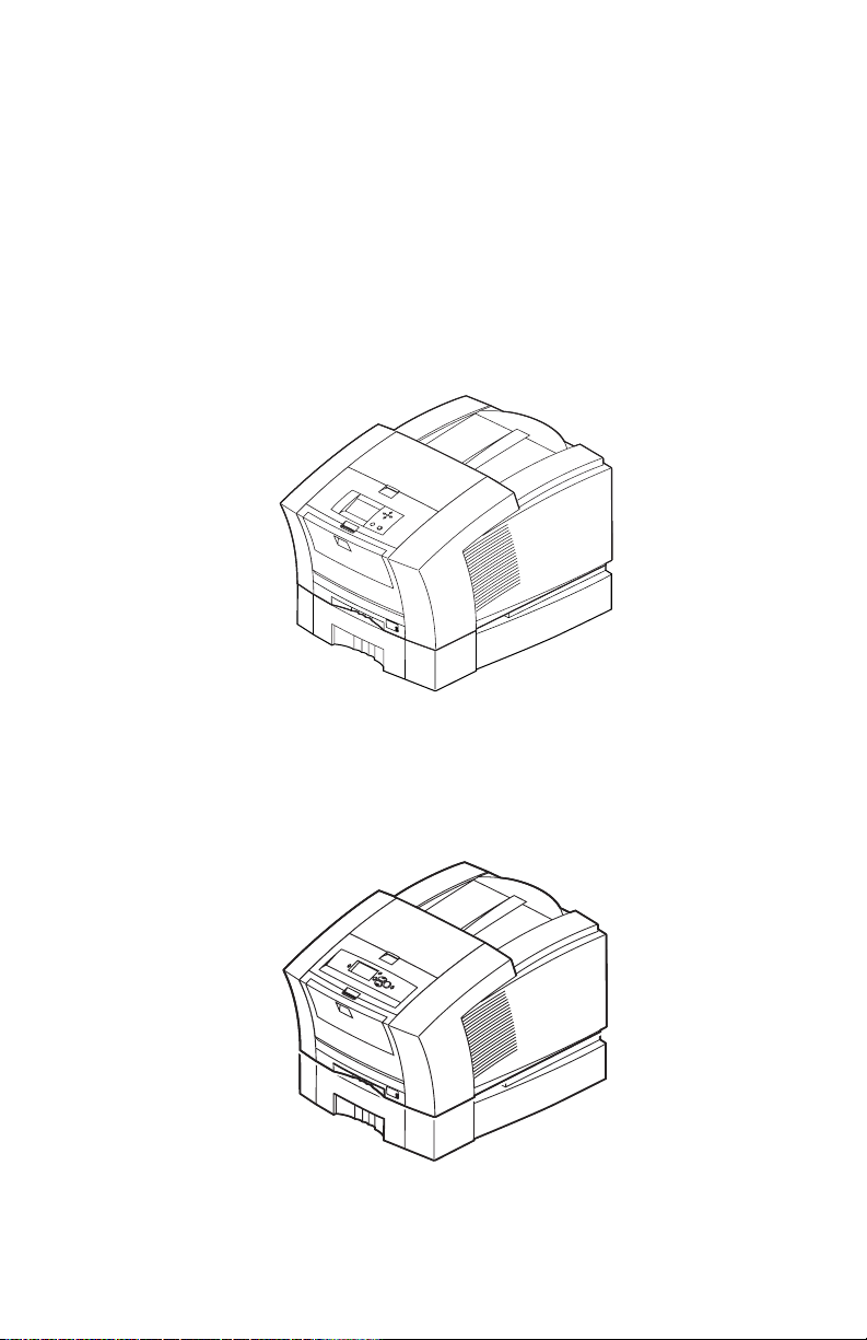
The Phaser 840/850 printer shown with optional High-Capacity Paper Tray Assembly. - - 1-1
The Phaser 860 printer shown with the optional High-Capacity Paper Tray Assembly.- - - 1-1
Internal features of the print engine - - - - - - - - - - - - - - - - - - - - - - - - - - 1-12
Circuit boards of the print engine (right front view of the Phaser 850)- - - - - - - - - - 1-13
Circuit boards of the print engine (left rear view Phaser 850) - - - - - - - - - - - - - - 1-14
Circuit Boards of the print engine (right rear view Phaser 860) - - - - - - - - - - - - - 1-14
The printer’s I
Printhead maintenance system of the print engine - - - - - - - - - - - - - - - - - - - 1-16
Sensors and switches on the right side of the print engine - - - - - - - - - - - - - - - 1-17
Switches and Sensors on the left side of the print engine - - - - - - - - - - - - - - - - 1-18
Solenoids and clutches on the print engine - - - - - - - - - - - - - - - - - - - - - - 1-19
Features of the Phaser 840 printer main board - - - - - - - - - - - - - - - - - - - - - 1-21
Features of the Phaser 860 Main Board - - - - - - - - - - - - - - - - - - - - - - - - 1-22
Features of the Phaser 850 printer main board - - - - - - - - - - - - - - - - - - - - - 1-22
Printer front panel - - - - - - - - - - - - - - - - - - - - - - - - - - - - - - - - - - 1-23
Front Panel - Phaser 860 - - - - - - - - - - - - - - - - - - - - - - - - - - - - - - - 1-24
Phaser 840 printer rear panel - - - - - - - - - - - - - - - - - - - - - - - - - - - - - 1-25
Phaser 850 printer rear panel - - - - - - - - - - - - - - - - - - - - - - - - - - - - - 1-26
Phaser 860 printer rear panel - - - - - - - - - - - - - - - - - - - - - - - - - - - - - 1-27
Attaching the service load connector to J250 - - - - - - - - - - - - - - - - - - - - - 3-83
Faceplate showing blade wipe with no drops, smudges or streaks - - - - - - - - - - - -3-107
Faceplate showing streaks and smudges from a poor wipe - - - - - - - - - - - - - - - 3-107
Connecting the vacuum gauge to the printer - - - - - - - - - - - - - - - - - - - - - -3-108
Maintenance tray showing good purge - - - - - - - - - - - - - - - - - - - - - - - -3-111
Damaged printhead data cable - - - - - - - - - - - - - - - - - - - - - - - - - - - -3-113
Inadvertently disconnected thermistor cable connector - - - - - - - - - - - - - - - - -3-114
Setting process belt tension - - - - - - - - - - - - - - - - - - - - - - - - - - - - - 4-139
Setting exit roller drive belt tension - - - - - - - - - - - - - - - - - - - - - - - - - -4-141
Pull the lever arm and press the tool firmly against the printer frame to set tension. - - - 4-143
Setting the Y-axis belt tension Phaser 850/860- - - - - - - - - - - - - - - - - - - - -4-145
Attaching clips. - - - - - - - - - - - - - - - - - - - - - - - - - - - - - - - - - - -4-146
Adjusting the tension spring - - - - - - - - - - - - - - - - - - - - - - - - - - - - -4-147
Drum adjustment - - - - - - - - - - - - - - - - - - - - - - - - - - - - - - - - - -4-148
Adjusting the x-axis scale adjustment - - - - - - - - - - - - - - - - - - - - - - - - -4-149
Aligning (timing) the cap/wipe/purge assembly drive belts - - - - - - - - - - - - - - - 4-151
Setting the drum position encoder gap- - - - - - - - - - - - - - - - - - - - - - - - - 4-153
Adjusting the transfix roller pressure springs - - - - - - - - - - - - - - - - - - - - -4-154
Connecting the vacuum gauge to the printer - - - - - - - - - - - - - - - - - - - - - -4-155
Resetting print engine NVRAM menu item - - - - - - - - - - - - - - - - - - - - - -4-157
Clearing PostScript NVRAM menu item - - - - - - - - - - - - - - - - - - - - - - -4-157
Lubricating the transfix cam - - - - - - - - - - - - - - - - - - - - - - - - - - - - -6-177
Removing the Phaser 840 printer main board - - - - - - - - - - - - - - - - - - - - -7-180
2
C bus - - - - - - - - - - - - - - - - - - - - - - - - - - - - - - - - - 1-15
List of Figures ix
Page 16

Removing the Phaser 850 printer main board - - - - - - - - - - - - - - - - - - - - 7-181
Removing the Main Board (Phaser 860) - - - - - - - - - - - - - - - - - - - - - - - 7-182
Removing the power supply- - - - - - - - - - - - - - - - - - - - - - - - - - - - - 7-183
Removing the power control board - - - - - - - - - - - - - - - - - - - - - - - - - 7-184
Remove the upper feed roller assembly (left side) - - - - - - - - - - - - - - - - - - 7-185
Removing the upper feed roller assembly (front) - - - - - - - - - - - - - - - - - - - 7-186
Removing the paper/drum heater - - - - - - - - - - - - - - - - - - - - - - - - - - 7-187
Removing the drum transfix assembly (left side) - - - - - - - - - - - - - - - - - - - 7-189
Removing the drum/transfix assembly (right side) - - - - - - - - - - - - - - - - - - 7-190
Marking the drum home flag sensor alignment - - - - - - - - - - - - - - - - - - - - 7-192
Removing the drum position sensor assembly (Phaser 840 printer) - - - - - - - - - - 7-193
Marking the shaft for drum home alignment - - - - - - - - - - - - - - - - - - - - - 7-194
Removing the drum position sensor assembly (Phaser 850 printer) - - - - - - - - - - 7-195
Plugging the reservoir holes- - - - - - - - - - - - - - - - - - - - - - - - - - - - - 7-196
Removing the printhead - - - - - - - - - - - - - - - - - - - - - - - - - - - - - - 7-197
Removing the x-axis motor and drive assembly - - - - - - - - - - - - - - - - - - - 7-199
Removing the Y-axis belt drive assembly (Phaser 840 printer) - - - - - - - - - - - - 7-200
Removing the Y-axis belt drive assembly (Phaser 850/860 printer) - - - - - - - - - - 7-201
Removing the cap/wipe/purge assembly (Phaser 840 printer) - - - - - - - - - - - - - 7-203
Removing the lower cap/wipe/purge retainer clip- - - - - - - - - - - - - - - - - - - 7-204
Removing the lower cap/wipe/purge retainer clip- - - - - - - - - - - - - - - - - - - 7-205
Removing the cap/wipe/purge assembly (Phaser 850/860 printer) - - - - - - - - - - - 7-206
Cabinet FRUs - - - - - - - - - - - - - - - - - - - - - - - - - - - - - - - - - - - 8-208
Imaging FRUs - - - - - - - - - - - - - - - - - - - - - - - - - - - - - - - - - - - 8-210
Paper path FRUs - - - - - - - - - - - - - - - - - - - - - - - - - - - - - - - - - - 8-212
Motor and fan FRUs - - - - - - - - - - - - - - - - - - - - - - - - - - - - - - - - 8-214
Circuit Board FRUs - - - - - - - - - - - - - - - - - - - - - - - - - - - - - - - - 8-216
Solenoid and Clutch FRUs - - - - - - - - - - - - - - - - - - - - - - - - - - - - - 8-218
Gear and belt FRUs- - - - - - - - - - - - - - - - - - - - - - - - - - - - - - - - - 8-220
Sensor and flag FRUs- - - - - - - - - - - - - - - - - - - - - - - - - - - - - - - - 8-222
High-capacity Paper Tray - - - - - - - - - - - - - - - - - - - - - - - - - - - - - - 8-224
New ink sticks - - - - - - - - - - - - - - - - - - - - - - - - - - - - - - - - - - PA-242
x Phaser 840/850/860/8200 Color Printer - Service Manual
Page 17
General Information
This service guide contains information used to verify operation, troubleshoot, repair,
adjust, and maintain the Xerox Phaser® 840, Phaser® 850 and Phaser® 860 Color
Printers. This guide includes a Field Replacement Unit Parts list. Topics such as printer
theory of operation, detailed removal/replacement procedures, configuration page details,
and verifying printer operation are located on the companion Color Printer Service &
Support Resources CD-ROM.
To ensure complete understanding of the product, we recommend participation in Phaser
840/850/860 printer service training.
0388-01
Fig 1-1 The Phaser 840/850 printer shown with optional
High-Capacity Paper Tray Assembly.
P860-001
Fig 1-2 The Phaser 860 printer shown with the optional
High-Capacity Paper Tray Assembly.
General Inormation 1 - 1
Page 18

Phaser 840 Printer Overview
The Phaser 840 Color Printer is an Adobe PostScript® Level 3 (Version 3010) color,
solid-ink printer. It also supports color PCL 5c at 600 x 600 dots-per-inch resolution. The
Phaser 840 printer prints at a number of resolutions: A 10 page-per-minute (ppm) Fast
Color Mode, a standard 5.7 ppm mode, an Enhanced mode of 491 x 982 dpi at 3.3 ppm
and a High-Resolution/Photo mode of 600 x 1200 dpi at 2.2 ppm. All printer models but
the standard version feature built-in automatic two-sided printing.
Standard Phaser 840N. The Standard Phaser 840 printer features 136 built-in fonts,
and is equipped with 32 Mbytes of RAM. It can be upgraded to as much as 128 Mbytes
of RAM using any combination of two 32-, and 64-Mbyte RAM DIMMs.
The Phaser 840DP. The Phaser 840 DP printer option upgrades the base printer to
64 Mbytes of RAM. It includes a SCSI port daughter card to support an external SCSI
disk for additional font storage as well as a scanner. Special circuitry on the SCSI port
daughter card enables additional features like duplex printing, job pipelining and First
page Preview mode. With job pipelining, the printer can print one image and process the
data for the next image at the same time. First Page Preview mode prints the first page of
a multiple page print job while holding the remainder of the job pending front panel
approval.
The Phaser 840DX. The extended features option has all the features of the Phaser
840 Plus printer but includes additional RAM to bring the printer to 128 Mbytes of RAM.
It also includes a High-capacity Paper Tray and an internal IDE hard drive.
The Phaser 840GP. This Designer Edition printer includes all the features of the
Phaser 840DP but includes 128 Mbytes of RAM, a 10/100BaseT network card, and
translucent blue cabinet panels.
The Phaser 840DPF. This freecolorprinters.com program printer is a Phaser 840DP
printer but it also includes a High-Capacity paper Tray and 3 years of onsite service.
All printers support four available paper trays: Two A and A4 trays are intended for paper
and low volumes of transparencies; two other A and A4 trays are meant for label stock and
high-volume transparencies. The optional 500-sheet High-capacity Paper Tray Assembly
gives the printer a two-tray capability. With the addition of a second High-capacity Paper
Tray, the printer has a three-tray capability. (The High-capacity Paper Tray Assembly is
sometimes referred to as a lower feeder; it only supports paper printing.) The printer can
also print six sizes of handfed envelopes.
1 - 2 Phaser 840/850/860/8200 Color Printer - Service Manual
Page 19

A 133-MHz PowerPC processor oversees print engine operations and PostScript image
processing. The printer features an integral bi-directional parallel port (IEEE 1284C with
ECP mode) and a 10BaseT Ethernet port (with support for EtherTalk, Novell
NetWare/NDS, TCP/IP, DHCP and Windows Peer-to-Peer). A USB high-speed serial port
is also provided. A rear panel slot allows customers to install one “smart card”
PhaserShare Series B Network Card. One card provides a LocalTalk port. A second,
alternative card offers a 10/100BaseT/10Base2 Ethernet board providing standard
protocol support for EtherTalk, Novell NetWare/NDS, TCP/IP and DHCP. When
installed, this card disables the standard 10baseT port. A third card provides a Token Ring
board providing protocol support for TokenTalk, Novell NetWare/NDS and TCP/IP.
When inserted, this card also disables the standard 10baseT port.
A second rear panel slot accommodates an internal IDE hard drive for print job collation,
job accounting, and font storage.
The printer features Job Accounting, which maintains from 50 to 5000 records of
processed print jobs, depending on memory options and hard drive options. The record
contains information such as time and duration of the print and the percentage of color
coverage on the print. The log of records can be retrieved using PhaserLink, PhaserShare
or CentreWare IS software.
General Information 1 - 3
Page 20

Phaser 850 Printer Overview
The Phaser 850 Color Printer is an Adobe PostScript Level 3 (Version 3010) color,
solid-ink printer. It also supports color PCL 5c at 600 x 600 dots-per-inch resolution. The
Phaser 850 printer prints at a number of resolutions: A 13.9 page-per-minute (ppm) Fast
Color Mode, a standard 7.9 ppm mode, an Enhanced mode of 450 x 818 dpi (with dot-size
switching) at 4 ppm and a High-Resolution/Photo mode of 600 x 1200 dpi at 2.2 ppm.
The printer also includes a 6.3 ppm Fast Transparency Mode and a 3.4 ppm Standard
Transparency Mode.
Standard Phaser 850N. The Standard Phaser 850 printer features 136 built-in fonts,
and is equipped with 32 Mbytes of RAM. It can be upgraded to configurations of 64, 128,
192, and 256 Mbytes of RAM using combinations of two 32-, and 64-, and 128-Mbyte
RAM DIMMs.
The Phaser 850DP. The Phaser 850DP printer option upgrades the printer to
64 Mbytes of RAM and includes additional features like 2-sided printing, job pipelining
and First Page Preview mode.
The Phaser 850DPF. This is a freecolorprinters.com program printer which includes a
High-Capacity paper tray and 3 years of on-site service.
The Phaser 850DX. The extended features DX option has all the features of the
Phaser 850DP printer, but includes additional RAM to bring the printer to 128 Mbytes of
RAM. It also includes a High-Capacity Paper Tray and an internal IDE hard drive.
Like the Phaser 840 printer, all printers support four available paper trays. They also
support the optional 500-sheet High-Capacity Paper Tray Assembly. The printer can also
print seven sizes of hand-fed envelopes.
A 200-MHz PowerPC processor oversees print engine operations and PostScript image
processing. The printer features a 10/100BaseT Ethernet port (with support for EtherTalk,
Novell NetWare/NDS, TCP/IP, DHCP and Windows Peer-to-Peer). A USB high-speed
serial port is also provided. A rear panel slot allows customers to install a Token Ring
card supporting TokenTalk, Novell NetWare/NDS and TCP/IP. When inserted, this card
also disables the standard 10/100BaseT port. LocalTalk and 10Base2 are not supported by
the Phaser 850 printer. A second rear panel slot accommodates an internal IDE hard drive
for print job collation, job accounting, font storage and PDF direct printing.
An integral bi-directional parallel port (IEEE 1284C with ECP mode) supports printing
and also allows connecting a parallel interface scanner for optical copying support.
Like the Phaser 840 printer, the Phaser 850 printer supports Job Accounting.
1 - 4 Phaser 840/850/860/8200 Color Printer - Service Manual
Page 21

Phaser 860 Printer Overview
The Phaser 860 Color Printer is an Adobe PostScript Level 3 (Version 3010) color,
solid-ink printer. It also supports color PCL 5c at 600 x 600 dots-per-inch resolution. The
printer can print at the following resolutions:
■ Fast Color mode, 16 page-per-minute (ppm)
■ Standard mode, 10 ppm mode at 355 x 464 dpi
■ Enhanced mode, 6 ppm at 464 x 928 dpi
■ High-Resolution/Photo mode, 3.5 ppm at of 600 x 1200 dpi.
The printer also includes a 7 ppm Fast Transparency mode and a 4 ppm Standard
Transparency Mode (double-pass). Both modes are at 355 x 464 dpi.
The Phaser 860B. The Phaser 860B printer features 136 built-in fonts, and is equipped
with 64 Mbytes of RAM. The Phaser 860B can be upgraded to configurations of 64, 128,
192 and 256 Mbytes of RAM using combinations of 64- and 128 Mbytes RAM
SODIMMs. The Phaser 860B does not support networking or High-resolution/Photo
mode.
The Phaser 860N. The Phaser 860N printer adds a 10/100 BaseT Ethernet port and
has all the same features as the Phaser 860B model.
The Phaser 860DP. The Phaser 860DP printer option upgrades the printer to
128 Mbytes of RAM and includes additional features like 2-sided printing, job pipelining
and High Resolution Photo mode.
The Phaser 860DPF. This is a freecolorprinters.com program printer. The Phaser
860DPF has all the features of the Phaser 860DP printer, but adds a High-capacity paper
tray and 3 years of on-site service.
The Phaser 860DX. The extended features DX option has all the features of the
Phaser 860DP printer, but includes a High-capacity Paper Tray and an internal IDE hard
drive.
All printers support five available paper trays: Two A and A4 trays are meant for paper
and low volumes of transparencies; two other A and A4 trays are meant for label stock and
high-volume transparencies; and a legal size paper tray which comes with an output bail.
There is an optional 500-sheet High-capacity Paper Tray Assembly gives the printer a
two-tray capability. With the addition of a second High-Capacity Paper Tray, the printer
has a three-tray capability. (The High-Capacity Paper Tray Assembly is sometimes
referred to as a lower feeder; it only supports paper printing.) The printer can also print
six sizes of hand-fed envelopes.
A 250-MHz PowerPC processor oversees print engine operations and PostScript image
processing. All configurations, except the Phaser 860B feature a 10/100BaseT Ethernet
port (with support for EtherTalk, Novell NetWare/NDS, TCP/IP, DHCP and Windows
Peer-to-Peer). A USB high-speed serial port is also provided. LocalTalk, Tolken Ring and
10Base2 are not supported by the Phaser 860 printer. An internal IDE hard drive can be
installed on the main board for font storage and job accounting, if the printer has DP
features the hard drive will support collation, proof print, saved print and secure print.
An integral bi-directional parallel port (IEEE 1284C with ECP mode) supports printing
and also allows connecting a parallel interface scanner for optical copying support.
General Information 1 - 5
Page 22

The printer supports Job Accounting which maintains from 50 to 5000 records of
processed print jobs, depending on memory and hard drive options. The record contains
information such as time duration of the print and the percentage of color coverage on the
print. The log of reconds can be retrieved using CentreWare software.
Proof Print Jobs. A proof job is a specific case of a multiple-copy job. With a proof
job, the customer assigns a password and copy account at the client workstation before
printing. The first set of prints are printed immediately. The original number of requested
sets are printed after the customer enters the matching password on the printer’s control
panel. The customer has the option of printing the original number of requested sets or
deleting the job. Using the same password will cause any previous job(s) to be deleted. A
proof job that has not been printed is retained on hard disk through power cycles. Proof
jobs sent to a printer without the hard disk option are not printed and are discarded.
Secure Print Jobs. Secure printing allows the customer to defer printing of a job until
a matching password is entered from the control panel. The customer assigns the
password at the client workstation before printing. The job is stored, and printing is
delayed until the password is entered on the printer’s control panel. Using the same
password will cause any previous jobs(s) to be deleted. A secure job that has not been
printed or released is retained on disk through power cycles. This function requires the
internal hard drive.
Saved Print Jobs.
Saved print allows the user to save print jobs to the internal hard drive of the printer. The
print job is not deleted after printing, it is stored on the hard drive for print on demand.
This function requires the internal hard drive.
Solid inks
Solid inks, sometimes called phase-change inks, are solid at room temperature and are
liquid at the higher temperature used during printing. The inks solidify almost instantly
after being jetted onto the printer’s drum. Because Xerox proprietary solid inks bleed
much less than ordinary liquid inks, they allow the printer to print brilliant colors on plain
paper.
Each Xerox solid-ink printer’s inks are especially formulated for that printer; the
inks are NOT interchangeable. Using the wrong ink in a printer may damage the
printhead or other subsystems. The Phaser 860 uses the ColorSticks® II ink formulation
which enables solid ink documents to be fed through auto-document feeders on copiers.
Note Turning the printer off and allowing it to cool causes it to perform
a printhead cleaning and purge cycle upon power-up. The
printer's purge cycle consumes a significant amount of ink.
During normal use and servicing, turn the printer off and allow it
to cool only when necessary.
1 - 6 Phaser 840/850/860/8200 Color Printer - Service Manual
Page 23

Phaser 840/850 RAM and Printer Capabilities
The Phaser 840 printer features two DIMM connectors which accept both 32- or
64-Mbytes RAM DIMMs (16-Mbyte RAM DIMMs work but are not offered). The
Phaser 850 printer features two DIMM connectors which will accept both 64- or
128-Mbytes RAM DIMMs. The printers can use SDRAM DIMMs meeting these
specifications:
■ 168-pin DIMM
■ Synchronous DRAM
■ 3.3 volts
■ 10 nsec speed
■ Valid on-board Serial Presence Detect ROM
■ Unbuffered
■ Latency of 2
■ 9 address columns (Phaser 850 printer allows 32-Mbytes DIMM to be in 8
columns)
■ Maximum of 2.8 cm (1.1 in.) in height (Phaser 840 printer only). SDRAM
DIMMs from other Phaser printers, such as the Phaser 740 and Phaser 780
color printers may be too tall to fit inside a Phaser 840 printer.
Upon power-up, the image processor interrogates the 256-byte Serial Presence Detect
EEPROM, which describes the DIMM in great detail, such as data width, clock delay,
number of address columns and row, refresh rate and more. If the DIMM does not meet
the required specifications, it will be ignored; no error message will be reported.
General Information 1 - 7
Page 24

Memory Considerations Phaser 840/850
With more memory, the printer dual-frame buffers for printing one image while
processing a second image (which gives greater printing throughput). The printer’s
capabilities can be increase as detailed in the following table.
For the Phaser 840 printer, adding RAM memory, and installing the SCSI daughter card
enables the Plus and Extended configurations features.
For the Phaser 850 printer, installing the DP Option code ROM module and adding RAM
enables these features.
Table 1-1 Installed RAM and printer capabilities
Feature (32 Mbytes)
Fast Color (draft)
printing
Standard Printing yes yes yes
Enhanced Printing yes yes yes
High-Resolution/
Photo Printing
2-sided printing no yes. The printer
Color PCL 5C yes yes yes
Pipelining no yes yes
Check Print no yes yes
Collation (requires
hard drive)
Job accounting 50 records 500 records. 5000
Frame buffer (lower
print resolutions can
provide additional
frame buffer space)
840N
850N
yes yes yes
no yes yes
no yes yes
1 Letter size image 1 Letter-size image 2 Letter-size images
(64 Mbytes)
840DP
850DP
supports fast,
standard and
enhanced 2-sided
prints
records with optional
hard drive
(128 Mbytes)
840DX
850DX
yes. The printer
supports 2-sided,
high-resolution,
1200 x 600 dpi print
5000 records with
included hard drive
1 - 8 Phaser 840/850/860/8200 Color Printer - Service Manual
Page 25

Print the Configuration Page and check the item “Installed RAM” to see what type of
RAM is installed.
For example:
Installed RAM: 64 Mbytes
Mem slot 1: SDRAM/parity/64 MB/KMM366S823BTL-G0
Mem slot 2: Empty
This is a list of SDRAM DIMMs that are branded for use by Xerox in this printer at the
time this guide was published:
Table 1-2 Acceptible SDRAM DIMMs
Size Maker Part Number Printer
32 Mbytes Samsung KMM366S403CTL-G0 840/850
32 Mbytes Micron MT16LSDT464AG-662XX 840/850
64 Mbytes Samsung KMM366S823BTL-G0 840/850
64 Mbytes Micron/Crucial CT8M64S4D10-MBTBGLP 840/850
32 Mbyte Samsung KMM366S424DTS-GL 850 (see note)
64 Mbyte Samsung KMM366S823DTS-GL 850
64 Mbyte Samsung KMM366S924BTS-GL 850
128 Mbytes Samsung KMM366S1623DT-GL 850
128 Mbytes Samsung KMM366S1724BT-GL 850
32 Mbytes Micron MT4LSDT464AG-662xx 850 (see note)
32 Mbytes Micron MT4LSDT464AG-10Exx 850 (see note)
64 Mbytes Micron MT8LSDT864AG-662xx 850
64 Mbytes Micron MT8LSDT864AG-10Exx 850
64 Mbytes Micron MT4LSDT864AG-662xx 850
64 Mbytes Micron MT4LSDT864AG-10Exx 850
128 Mbytes Micron MT16LSDT1664AG-662xx 850
128 Mbytes Micron MT16LSDT1664AG-10Exx 850
Note The 32-Mbyte DIMM marked for 850-only are not compatible
with the other RAM DIMMs because the 32-Mbyte RAM DIMM is
an 8-column type; the other DIMMs are 9-column types.
If one of each type is installed in the Phaser 850 printer, only the
9-column DIMM will be enabled.
General Information 1 - 9
Page 26

Phaser 860 RAM and Printer Capabilities
The Phaser 860 printer features two SODIMM connectors which accept off the shelf
64MB or 128 MB SODIMM SDRAM memory modules meeting these specifications:
■ 144-pin SODIMM
■ Synchronous DRAM
■ 3.3 volts
■ PC100 compliant
■ Valid on-board Serial Presence Detect ROM
■ Built using 64 or 128Mbit SDRAM parts
■ 100MHz operation at CAS Latency = 2
Upon power-up, the image processor interrogates the Serial Presence Detect EEPROM,
which describes the SODIMM in great detail, such as data width, clock delay, number of
address columns and row, refresh rate and more. If the SODIMM does not meet the
required specifications, it will be not be used. If there are no good SODIMMs you will
receive a RAM error. If one SODIMM is good you will receive a temporary error message
and the printer will continue with power up.
Print the Configuration Page and check the item “Installed RAM” to see what type of
RAM is installed.
This is a list of SODIMMs that are branded for use by Xerox in this printer at the time this
guide was published:
Table 1-3 Acceptible SODIMMs
Size Maker Part Number
64 Mbytes Samsung 156-4831-00
64 Mbytes Micron MT8LSDT864HG-10E
128 Mbytes Samsung 156-4832-00
128 Mbytes Micron MT8LSDT1664HG-10E
1 - 10 Phaser 840/850/860/8200 Color Printer - Service Manual
Page 27

Memory Considerations Phaser 860
With more memory, the printer dual-frame buffers for printing one image while
processing a second image (which gives greater printing throughput). The printer’s
capabilities can be increase as detailed in the following table.
For the Phaser 860 printer, installing the DP Option code ROM module and adding RAM
enables these features.
Table 1-4 Installed RAM and printer capabilities
Feature (64 Mbytes)
Fast Color (draft)
printing
Standard Printing yes yes
Enhanced Printing yes yes
High-Resolution/
Photo Printing
2-sided printing no yes. The printer
Color PCL 5c yes yes
Pipelining no yes
Collation (requires hard
drive)
Job accounting 500 records. 500 records. 5000
Frame buffer (lower print
resolutions can provide
additional frame buffer
space)
Proof Print
Secure Print
Saved Print
(Requires Hard Drive)
860B
860N
yes yes
no yes
no yes
1 Letter-size image 2 Letter-size images
no yes
(128 Mbytes)
860DP
860DPF
860DX
supports 2-sided,
high-resolution,
1200 x 600 dpi print
records with included
hard drive
General Information 1 - 11
Page 28
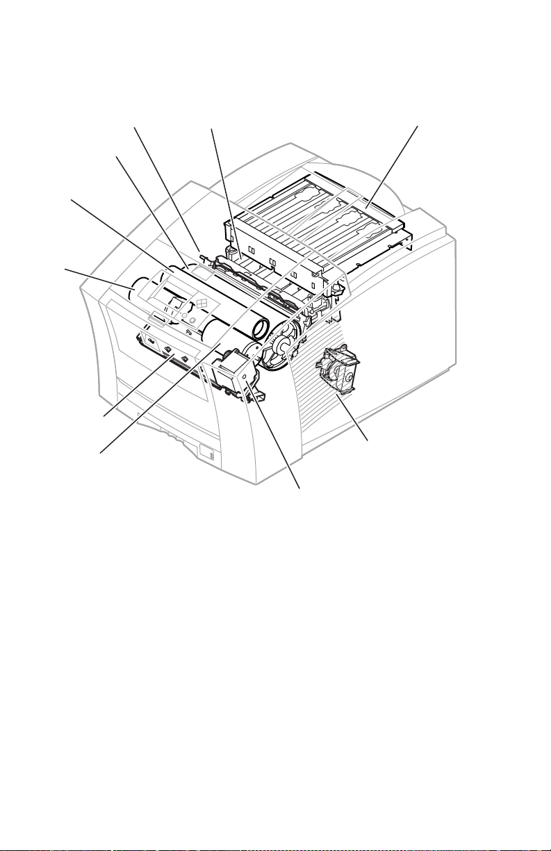
Print Engine Assemblies 840/850/860
0
Cap/wipe/purge
assembly
Drum
Transfix
roller
rocess
otor
Paper/
drum heater
Y-axis
motor
Printhead
Paper feed
motor
Ink load
assembly
X-axis drive
and motor
0388-
Fig 1-3 Internal features of the print engine
1 - 12 Phaser 840/850/860/8200 Color Printer - Service Manual
Page 29
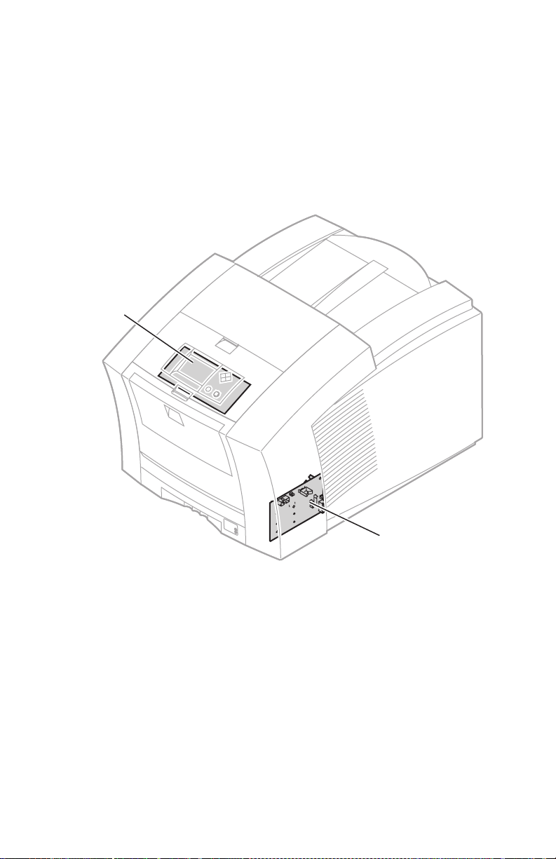
Circuit Boards
Seven circuit boards support the printer’s electronics. Two boards, called I/O boards (left
and right), support the front panel, solenoids and sensors. The main board contains the
printer’s CPU processor, RAM and ROM. The power control board distributes power
supply voltages to the other printer boards and many of the printer motors. The power
supply converts the AC line voltage into internal AC and DC voltages. The front panel
provides a user interface to the printer. The printhead drive board, a part of the printhead,
manages the signals and voltages of the printhead’s printing elements and sensors. The
optional network card (Phaser 840 and 850 only) and internal hard drive could be
considered eight and ninth circuit boards.
Front
panel
I/O board
right
0388-03
Fig 1-4 Circuit boards of the print engine (right front view of the
Phaser 850)
General Information 1 - 13
Page 30
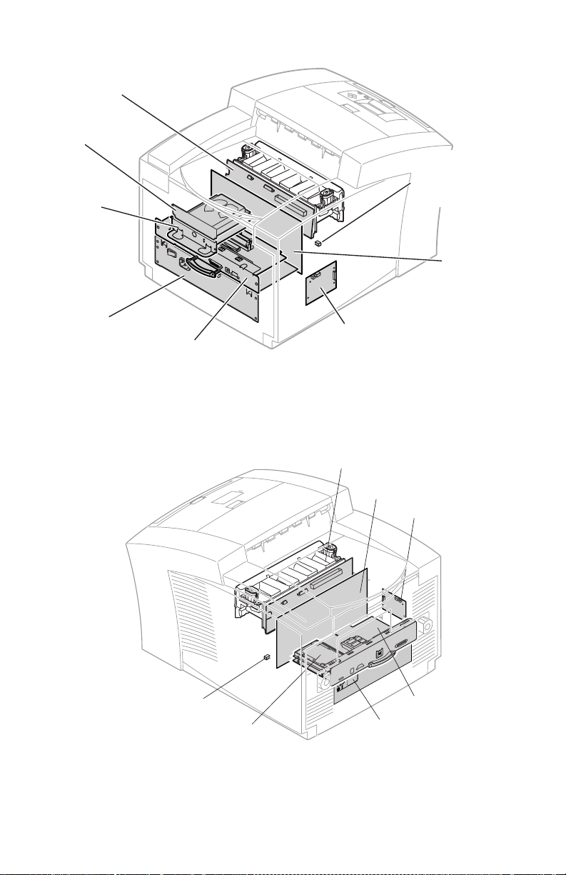
Printhead drive
board
Internal hard
drive
Drum
Maintenance
counter
Network
EEPROM
card
Power
supply
I/O board
Main board
left
Fig 1-5 Circuit boards of the print engine (left rear view Phaser 850)
Printhead
Drive Board
Power Control
Board
I/O Board left
Power
control
board
0388-04
Drum Maintenance
Counter EEPROM
Internal Hard Drive
Main Board
Power Supply
P860-004
Fig 1-6 Circuit Boards of the print engine (right rear view Phaser 860)
1 - 14 Phaser 840/850/860/8200 Color Printer - Service Manual
Page 31

The printer’s I2C bus
An internal data bus, called the I2C bus, connects all I/O boards to the main board.
Through this single bus, the main board can “poll” the I/O boards for the state of the
printer’s sensors as well as actuate the printer’s solenoids. This data bus greatly simplifies
the wiring that would otherwise be required for monitoring numerous sensors and
solenoids. The I
2
C bus also extends down to the High-Capacity Paper Trays.
High-capacity
Paper Tray
connection
Fig 1-7 The printer’s I2C bus
I2C bus
0388-05
General Information 1 - 15
Page 32

Printhead Maintenance System
The printer features a printhead maintenance system used to clean the printhead faceplate
and clear clogs from the printhead nozzles. The system consists of a vacuum pump
assembly, the cap/wipe/purge assembly and the cap/wipe/purge carriage drive.
Cap/wipe/purge
carriage drive
Cap/wipe/purge
assembly
Fig 1-8 Printhead maintenance system of the print engine
1 - 16 Phaser 840/850/860/8200 Color Printer - Service Manual
Vacuum
pump
assembly
0388-06
Page 33

Sensor Maps
Sensors in the printer provide information to the main board to determine the state of the
printer. The printer monitors the positions of some of the movable assemblies, such as the
drum, as well as the temperature of many other assemblies, such as the printhead, paper
preheater and the drum.
Note Unlike the Phaser 840 printer, the Phaser 850 /860 printer does
not have a separate drum-home position sensor.
Ink-load
cover sensor
Top cover
switch
Front cover
switch
Preheater
entry/left
edge sensor
Ink-sticklow sensor
Ink-stickout sensor
Exit / tray-full
sensor
A4-size media
sensor
A-size media
sensor
Cap/wipe/purge
home sensor
Maintenance
blade position
sensor
Hand-feed
sensor
Paper-pick
sensor
Tray type
sensors
Paper-empty
sensor
Fig 1-9 Sensors and switches on the right side of the print engine
General Information 1 - 17
0388-07
Page 34

Transfix exit
sensor
Drum
temperature
sensor
Duplex
paper sensor
Drum-homeposition sensor
(Phaser 840 only)
Drum encoder
sensor
Preheater
exit sensor
Process
gear position
sensor
Transfix
roller
Preheater
exit sensor
located on inside
Preheater
wall of drum/transfix
frame
Drum
Fig 1-10 Switches and Sensors on the left side of the print engine
1 - 18 Phaser 840/850/860/8200 Color Printer - Service Manual
0388-34
Page 35

Caution The actual position of some printer assemblies, such as the
8
printhead or the cap/wipe/purge assembly, cannot be ascertained
at all times. The printer records, in NVRAM, where it last
positioned such assemblies each time it moves them. If, after
power-down or a power interruption, the assemblies are manually
repositioned, the printer erroneously assumes that the assemblies
are in the position it last left them. This assumption can result in
damage to the printer when it tries to position the assemblies. For
example, the printhead could be tilted forward and crash into the
raised cap/wipe/purge assembly.
Before turning on the printer, ensure the printhead is tilted
forward, centered in front of the drum and the cap/wipe/purge
assembly is in the retracted, home position. The tilt cam gear
should be disengaged from the gear drive train.
Electric clutches and solenoids are used by the printer to engage rollers as needed to move
paper through the printer as well as start some print processes.
Upper feedroller clutch
Pick clutch
Drum maintenance
cam clutch
Cap/wipe/purge
clutch
Air valve
solenoid
Transfix
solenoid
Fig 1-11 Solenoids and clutches on the print engine
General Information 1 - 19
0388-0
Page 36

Combination sensors and their meanings
Combinations of sensors are used by the printer to determine the type of standard (or
upper) media tray installed in the printer.
Media tray type sensing
The combinations of the three tray sensors inform the print engine what type of media tray
is installed. (The print engine does not detect the type of media installed in the tray; it
only detects the particular tray being used by the presence of sensor flags on the side of the
tray.) The tray sensors are located on the right-side interior of the paper tray slot, mounted
on I/O board right. There are five tray types:
■ Letter (A-size). This tray is sized for 8.5 x 11-inch (U.S.) paper as well as
low-volumes of A-size transparency film.
■ Metric Letter (A4-size). This tray is used for 210 x 297 mm (Metric) paper as
well as low-volumes of A4-size transparency film.
■ High-volume Transparency/Label (A). This tray supports high volumes of
U.S.-size transparency film as well as laser quality, adhesive label stock.
■ High-volume Transparency/Label (A4). This tray supports high volumes of
Metric-size transparency film as well as laser quality, adhesive label stock.
■ Legal Tray (Phaser 860 only) This tray supports Legal-size, US 8.5 x 14 inch
paper.
Table 1-5 Tray switch sensor combinations
Tray type A Paper A4 Paper A
Top switch Closed Open Closed Open Closed
Middle switch Open Closed Open Closed Closed
Bottom
switch
Open Open Closed Closed Open
The slide switch actuators on the media trays will open a
switch in the forward position and close a switch in the rear
position.
Transparency
A4
Transparency
Legal Size
1 - 20 Phaser 840/850/860/8200 Color Printer - Service Manual
Page 37

The Main Board
The main board features the printer’s PowerPC 603e processor that controls the engine
and the PostScript processing. Prominent on the main board is the ROM code DIMM and
the RAM DIMM plug-in modules. The code ROM DIMM also contains the printer’s
on-board fonts. For the Phaser 840, alternate ROM code DIMMs contain language fonts
such as Kanji or Hangul. The Phaser 850 printer support two base Heisei Kanji fonts;
other Asian fonts are available on the internal IDE drive. For the Phaser 860, all Asian
fonts are available on the internal IDE drive.
Network connection is provided through a built-in 10BaseT port in the Phaser 840 printer
and a 10/100BaseT port for the Phaser 850/860 printer (not enabled in the Phaser 860B).
For the Phaser 840 printer, a plug-in SCSI interface adapter board provides a SCSI port for
an external hard drive or scanner.
The Phaser 840 printer stores unique printer status and PostScript values in its socketed
NVRAM and EEPROM modules. The printer’s Ethernet address, unique to each printer,
is stored in the EEPROM (printer ID chip), an 8-pin socketed IC.
For the Phaser 850/860 printer, all printer NVRAM parameters, such as the printer ID,
unique printer status and PostScript values, and Ethernet address, are all stored in the
socketed EEPROM.
All socketed components should be transferred to a replacement main board to maintain
customer-unique settings.
SCSI riser
board
EEPROM
Printer ID
RAM DIMMs
NV RAM/
Real Time Clock
Code ROM
DIMM
Fig 1-12 Features of the Phaser 840 printer main board
General Information 1 - 21
0388-09
Page 38

EEPROM
Printer ID
RAM DIMMs
Code ROM
module
Fig 1-13 Features of the Phaser 850 printer main board
0388-76
Factory Code ROM
EEPROM
Printer ID
RAM SODIMMs
Hard Drive
Fig 1-14 Features of the Phaser 860 Main Board
ROM Upgrade
Code DIMM
P860-002
1 - 22 Phaser 840/850/860/8200 Color Printer - Service Manual
Page 39

Front Panel - Phaser 840/850 Printers
These front panel features are found on the printer:
■ 128 x 64 pixel backlighted graphic display
■ Two push buttons and four arrow buttons
■ Two L ED s
LCD. The backlighted LCD serves two purposes: displaying current image processor
and print engine status information and displaying an interactive menu. Status
information includes image processor status such as Ready to print, Receiving
data and Printing. Print engine status includes messages such as Outofpaper,
Paper Jam, Add ink as well as error messages.
Customers can review and modify certain NVRAM, I/O ports and peripheral parameters.
Buttons. Four of the six buttons are arranged as a diamond-shaped keypad. The other
two buttons are used as Select and Help.
Refer to "Check Value Menu Parameters", on page 4-135 for details on using the front
panel controls to enter special printer modes.
The topic "Resetting NVRAM", on page 4-156 explains how to use the front panel buttons
to reset the NVRAM to its factory-default values.
Navigation
buttons
Power
Error
Fig 1-15 Printer front panel
READY TO PRINT
Help
button
Select
button
0388-10
General Information 1 - 23
Page 40

Front Panel - Phaser 860
OK
These front panel features are found on the printer:
■ 128 x 64 pixel backlighted graphic display
■ Four push buttons and two arrow buttons
■ One LED status indicator
LCD. The backlighted LCD serves two purposes: displaying the current image processor
and print engine status information and displaying an interactive menu. Status
information includes an image processor status such as Ready to print,
Receiving data and Printing. Print engine status includes messages such as
Outofpaper; Paper Jam; Add ink and error messages.
Customers can review and modify certain NVRAM, I/O ports and peripheral parameters.
Buttons.
1. Status Indicator light
2. LCD Display Screen
3. Cancel
4. Back or Exit
5. Scroll Up and Scroll Down
6. OK
7. ‘i’ will display additional or help infromation regarding the message or menu item
currently displayed on the screen.
Refer to "Front Panel Shortcuts", on page 4-119 for details on using the front panel
controls to enter special printer modes.
The topic "Resetting NVRAM", on page 4-156 explains how to use the front panel buttons
to reset the NVRAM to its factory-default values.
5
Phaser 860
OK
123467
0726-42
Fig 1-16 Front Panel - Phaser 860
1 - 24 Phaser 840/850/860/8200 Color Printer - Service Manual
Page 41

Rear Panel Connections
1
Phaser 840 printer connectors
The rear panel of the Phaser 840 printer features the host interface connectors to the
printer:
■ Standard parallel (high-density connector), IEEE 1284C.
■ Twisted Pair (10BaseT) Ethernet connector.
■ A Universal Serial Bus port.
■ Optional SCSI high-density connector (hard disk drive or Tektronix-approved
scanner).
■ A special 5-pin connector accommodates a service RS-232 cable from a PC or
Macintosh computer running PC-based diagnostics.
The rear panel also includes two option slots. With the addition of a PhaserShare network
card in one slot, the printer can feature either of these connector combinations:
■ LocalTalk connector
■ ThinNet (10Base2) and Twisted Pair (100BaseT) Ethernet or Token Ring
connectors.
Note When an Ethernet or Token Ring PhaserShare card is installed,
the printer’s built-in 10BaseT Ethernet port is disabled.
The second slot accommodates an internal IDE hard drive for print job collation, job
accounting, font storage and PDF direct printing.
TM
PhaserShare
Series B
Ethernet Card
SCSI
TX
RX
100
Mbs
TP
LINK
10/100Base-TX
Ethernet
10Base2
10BaseT
Service
RS-232
Fig 1-17 Phaser 840 printer rear panel
IDE hard drive
Network card
PostScript
health
light
Parallel
USB
DIP
switches
General Information 1 - 25
Engine
health
light
0388-
Page 42

Phaser 850 printer connectors
The rear panel of the Phaser 850 printer features the host interface connectors to the
printer:
■ Standard parallel (high-density connector), IEEE 1284C. For the Phaser 850
printer, it can also be used to connect a parallel-interface scanner
■ Twisted Pair (10/100BaseT) Ethernet connector.
■ A Universal Serial Bus port.
■ A special 5-pin connector accommodates a service RS-232 cable from a PC or
Macintosh computer running PC-based diagnostics.
The rear panel also includes two option slots. One slot accommodates a Token Ring Card.
When the Token Ring card is installed, the printer’s built-in 10/100BaseT Ethernet port is
disabled.
The second slot accommodates an internal IDE hard drive for print job collation, job
accounting and font storage.
IDE hard drive
Optional Token
Ring card
PostScript
health
light
Ethernet
10/100BaseT
Service
RS-232
Parallel
USB
DIP
switches
Fig 1-18 Phaser 850 printer rear panel
1 - 26 Phaser 840/850/860/8200 Color Printer - Service Manual
Engine
health
light
0388-77
Page 43

Phaser 860 printer connectors
The rear panel of the Phaser 860 printer features the host interface connectors to the
printer:
■ Standard parallel (high-density connector), IEEE 1284C. For the Phaser 860
printer, it can also be used to connect a parallel-interface scanner
■ Twisted Pair (10/100BaseT) Ethernet connector.
■ A Universal Serial Bus (USB) port.
■ An optional hard drive can be installed on the main board.
■ Optional Network cards are not supported for the Phaser 860.
Ethernet
TP
RCV
XMT
Service
Only
USB
RESET
4
1 2 3
PS PE
Fig 1-19 Phaser 860 printer rear panel
Parallel
P860-005
General Information 1 - 27
Page 44

Rear Panel Status LEDs
Two LEDs on the rear panel indicate the status of the printer’s CPU functions: PostScript
processing and print engine control or diagnostics.
1. PostScript health light (LED) normally blinks once per second.
2. Engine health light (PE LED) normally blinks twice every 2.5 seconds.
3. During the first minute of power-up the LEDs are used to indicate diagnostic progress
refer to "System power-up sequence", on page 3-76.
4. If the LEDs stop blinking for more than a minute refer to the topic "Error Codes and
Messages", on page 2-37.
5. If the LEDs are blinking in a repeating pattern, other than normal operating health
status as described, refer to the topic "Error Codes and Messages", on page 2-37.
DIP Switches
Four DIP switches allow you to reset the printer or place the printer in different operating
modes. You must set the switches before power is turned on to enter the selected mode.
Table 1-6 Rear panel DIP switch settings
Function Switch 1 Switch 2 Switch 3 Switch 4
Normal operating mode UP UP UP* UP
Service mode DOWN UP UP UP
Reset printer UP* UP* UP* DOWN
Manufacturing mode (Bypass
mode)
Development mode (engineering
use only)
Recovery mode (engineering use
only)
* Recommended DIP switch postion.
** If DIP switch 4 is left in the down position the printer will not turn off.
UP DOWN UP* UP
DOWN DOWN DOWN* UP
DOWN UP DOWN UP
then UP**
1 - 28 Phaser 840/850/860/8200 Color Printer - Service Manual
Page 45

Phaser 840, 850 and 860 Printer Differences
Note There are additional part differences not detailed in this table.
Please refer to "FRU Parts List", on page 8-207 for a complete
listing of parts and part numbers.
Table 1-7 Summary of differences between Phaser 840/850/860
Phaser 840 Part
Description
Main board The main board is based on a 603E
RAM DIMMs Phaser 850 printer is not as
Power control
board
Printhead The Phaser 850 printhead mount
Y-axis pulley
assembly
Cap/wipe/purge
assembly
Preheater entry
flags
840 to 850 Difference 850 to 860 Difference
processor at 200 MHz. It features a
new rear panel with built-in
10/100BaseT and no SCSI port or
riser card. The large Dallas NVRAM
chip is no longer used. Also the
RAM connectors are angled. A
battery on the main board will
support the real-time clock (10 year
life). The printer supports up to 256
Mbytes of RAM. Only a Token Ring
Card and an IDE Internal Hard Drive
are available.
restricted on the height of the RAM
DIMMs the main board will accept
since it uses angled RAM DIMM
connectors. PC66 compliant.
Improved fusing. Resettable fuses
(by disconnecting AC power) on +5v
and +40v High-Capacity Paper Tray
leads. No x-axis fuse.
has been factory calibrated so no
head-to-drum adjustment is required
when installing the printhead (as
long as the printhead’s four
mounting screws have not been
loosened nor the printhead tilt
setting altered on the left side of the
frame).
The Y-axis pulley assembly now
features a built-in spring tension. A
Y-axis belt tension tool is not
required.
This is a new assembly. It also uses
a new mounting system that does
not require the disassembling of the
timing belts in order to remove the
cap/wipe/purge assembly
New sensor flags, less prone to
snagging paper when jammed paper
is pulled from the printer, are
mounted on the upper feed roller
assembly.
The 8240 processor at 250 MHz.
Internal Hard drive now mounted
on the main board.
No network cards are supported.
Code ROM is usually soldered
down.
Easier insertion.
New integrated ASICs.
Uses the smaller 144-pin
SODIMMs.
PC100 compliant.
40V service load connector no
longer needed.
Internal changes to support new
ColorStix
New Y-Axis pulley assembly
made of aluminum to imporve
print quality and reduce noise.
® II ink.
General Information 1 - 29
Page 46

Table 1-7 Summary of differences between Phaser 840/850/860
Phaser 840 Part
Description
Left I/O board A new left I/O board.
Right I/O board New board to support the new
Y-axis drum
encoder assembly
Lower stripper
blade holder and
stripper blade
Rollers and
clutches
Preheater A new paper preheater designed to
Inks
Ink is NOT
interchangeable
between models.
Legal Tray w/Bail New feature for the Phaser 860
High-Capacity
Paper Tray
Assembly
Front Panel Display Improved design for ease of
840 to 850 Difference 850 to 860 Difference
front panel.
A new Y-axis drum encoder is used,
which does not use a separate drum
home sensor.
The lower stripper fingers of the
have been replaced with a
replaceable stripper blade, called a
rapid release guide, and a guide
holder which is backward compatible
to the Phaser 840.
Phaser 850 roller shafts are
re-tooled for clutches with C-clips
instead of the Phaser 840 printer’s
snap-fit feature. The parts are
reversed compatible only if the shaft,
clutch and e-ring combination
replace the Phaser 840 parts. The
bushings for the Phaser 850’s
duplex roller are installed with
C-clips from the inside of the
chassis.
A new Drum Maintenance clutch is
used in the Phaser 850 printer to
dramatically improve reliability.
accommodate the travel of the paper
preheater entry flags is used in the
Phaser 850 printer. The preheater
is reverse compatible into the
Phaser 840 printer.
The Phaser 850 printer uses new
inks using a different formulation.
Color change.
Round pick roller to improve
reliablility.
The pick roller now uses the
same clutch as the upper feed
roller and the cap/wip/purge
drive.
New Drum Maintenace Cam to
support new Drum Maintenance
alogrithms.
New ColorStix
specific to the Phaser 860.
only.
Reliability improvements. These
improvements are also being
made on the Phaser 840 and
850.
navigation.
Service diagnostics are
accessible through the Front
Panel, for more information refer
to "Front Panel Shortcuts", on
page 4-119.
Reduced ESD susceptibility.
® II formulation
1 - 30 Phaser 840/850/860/8200 Color Printer - Service Manual
Page 47

Specifications
Table 1-8 Physical dimensions
Dimensions Value
Height: 38.7 cm. (15.25 ins.)
Width: 40 cm (17.25 ins.)
Depth: 57.8 cm (22.75 ins.)
Weight: Approximately 36 kgs (79 lbs.) Print engine weight only;
Table 1-9 Printer installation clearances
Clearances Value
Top: 45.7 cm (18 ins.)
Left: 10.2 cm (4 ins.)
Right: 10.2 cm (4 ins.)
Front: Unrestricted to replace trays and clear paper jams
Rear: 10.2 cm (4 ins.)
Bottom: No obstruction under printer that could block its cooling vents.
Mounting surface
flatness:
51.4 cm (20.25 ins.) with one High-Capacity Paper Tray Assembly
64.1 cm (25.25 ins.) with two High-Capacity Paper Tray Assemblies
add 9 kgs (20 lbs.) for each optional High-Capacity Paper Tray
Assembly.
Within 3 degrees of horizontal with all four feet in contact with the
surface.
General Information 1 - 31
Page 48

Table 1-10 Functional specifications
Characteristic Specification
Printing process Solid-ink onto plain paper.
Color medium Cyan, magenta, yellow and black ink sticks, each shape-coded. The
Addressability Phaser 840 printer: Selectable 273 x 300, 409 x 409, 491 x 982 or
Engine printing speed
(single-sided)
Minimum printing
margins
Maximum print area A-size: 8.1 x 10.6 in.
Usable paper sizes Tray fed: A-size and A4-size, legal-size (860 only), auto-duplex
Usable paper weights Tray-fed:
printer uses the subtractive color system to produce the colors red,
green, and blue.
600 x 1200 dots-per-inch (horizontal and vertical).
Phaser 850 printer: Selectable 177 x 409, 355 x 464, 450 x 818 or
600 x 1200 dots-per-inch (horizontal and vertical).
Phaser 860 printer: Selectable 205 x 409, 355 x 464, 464 x 927 or
600 x 1200 dots-per-inch (horizontal and vertical).
Phaser 840 Phaser 850 Phaser 860
Fast Color 10.0 14.0 15.9 ppm
Standard 5.7 7.8 10.0 ppm
Enhanced 3.3 4.4 6.4 ppm
Photo 2.2 2.2 3.6 ppm
Fast Tranperancy 5.0 6.3 7.0 ppm
Standard Transperancy 2.7 3.5 3.5 ppm
Print times do not include image processing time, which varies due
to image complexity. 25 mm (1 in.) margins assumed with 35% ink
coverage.
All sides: 5 mm (0.2 in.)
Legal size: 1 inch (Top and Bottom) 5mm (right and left sides)
Envelope margins vary, see user guide for specifications.
A4-size: 200 x 283 mm
Legal size: 8.1 x 12 in. (Phaser 860 only)
Manual fed: A-size and A4-size, legal-size (860 only), auto-duplex
Phaser 850/860 only, single-sided printing only
Executive (7.25 x 10.5 in.)
A5 (148 x 210 mm)
16 - 32 lb. Bond (60 - 120 g/m
16 - 40 lb. Bond (60 - 150 g/m
up to 65 lb. (176 g/m
2
) Cover stock (main tray only)
2
) (Phaser 840)
2
) (Phaser 850/860)
single-sided*
20 - 28 lb. Bond Legal size (Phaser 860 only)
Manual-fed:
16 - 40 lb. Bond (60 - 150 g/m
up to 80 lb. Cover (135 - 220 g/m
up to 110 lb (216 g/m
2
20 - 28 lb. Bond Legal size (860 only)
*Note: media up to 150 g/m
2
)
2
) -single-sided*
) Index stock
2
can be auto-duplexed. Tektronix/Xerox
brand cover paper and glossy paper exceed this specification
but are supported.
1 - 32 Phaser 840/850/860/8200 Color Printer - Service Manual
Page 49

Table 1-10 Functional specifications
Characteristic Specification
Usable envelopes #10 (U.S.) DL (Metric)
Specialty Media Labels : A/A4 laser quality sheet stock only, Recommended Avery®
#6 3/4 (U.S.) Choukei 3 Gou
C5 (Metric) Choukei 4 Gou
US Monarch (Phaser 850/860 printer only)
Note: Do not use envelopes with endflaps (except Choukei 3 &
4 Gou), plastic windows or metal clasps; they can damage the
printer.
white laser labels:
Phaser 840/850/860 use: Tek-branded labels.
The Phaser 840 also supports: U.S.: 5160, 5960 and Metric: L7162.
The Phaser 840/850/860 also support:
Glossy, Photo, Cover stock and Transparencies
Table 1-11 Electrical specifications
Characteristic Specification
Primary line voltages 87 to 132 VAC (115 VAC nominal)
Primary voltage
frequency range
Power consumption 200 watts standby; 300 watts at idle; 600 watts during printing.
Current rating 115 VAC configuration – 8 amp max./1 amp min.
Fusing F1: DC switcher – 6.3 amp slo-blo
Secondary voltages +5V ± 2.5%
174 to 264 VAC (220 VAC nominal)
Input voltage range is auto-sensed.
47 to 63 Hz
Maximum power consumption 1000 watts during warm-up.
220 VAC configuration – 4 amp max./1 amp min.
F2: Drum heater 1, reservoir heater 1, ink melt chambers,
cap/wipe/purge unit – 10 amp slo-blo
F3: Jet stack left and right, paper pre-heaters, reservoir heaters 2,
3,and 4 – 10 amp slo blo
Fuses are not user-accessible.
+12 V ± 5%
-12 V ± 5%
+40 V -5%, +12%
-52 V ± 10%
+54 V ± 10%
General Information 1 - 33
Page 50

Table 1-11 Electrical specifications
Characteristic Specification
RF emissions Both 115 and 220 VAC-configured instruments pass these standards:
EC EN60950:1992 Safety of Information Technology Equipment
including Business Equipment
EC EN55022:1992 Limits and methods of measurement of radio
interference characteristic of Information Technology Equipment
EC EN50082-1:1997 The Generic Immunity Standard Residential,
Commercial, and Light Industry
EN61000-4-3:1995-02 RF Field Immunity
EN61000-4-2:1995-01 ESD (Electostatic Discharge)
EN61000-4-4:1995-01 Fast Burst Transient
EN61000-4-5:1995-02 Line Surge
EN61000-4-6:1996-03 RF conducted Immunity
EN61000-4-11:1994-06 Voltage Dips and Interruptions
EN61000-3-3:1994-12 Flicker
73/23/EEC Low Voltage Directive
89/336/EEC Electromagnetic Compatibility Directive
89/392/EEC Machinery Directive
Table 1-12 Environmental specifications
Characteristic Specification
Temperature
Operating
Storage and shipping
Humidity
Operating
Non-operating
Altitude
Operating
Non-operating
Vibration/shock
Non-Operating
(vibration)
Non-operating (shock)
°
10 to 32
-30 to 60
10 to 80% relative humidity, non-condensing
10 to 95% relative humidity, non-condensing
0 to 2400 m (8,000 ft.) at 25
0 to 15000 m (50,000 ft.)
Will withstand 0.15 G excitation, 5 to 200 Hz, 3 axes for up to
7 minutes with no impairment or subsequent damage.
0.5 g, 25 minute sweep, 5-200-5 Hz, 100-200 sec/sweep cycles.
C (50 to 90° F)
°
C (-22 to 140° F)
°
C
Operating (shock)
The printer may have any corner raised and dropped 1.5 cm (0.6 in.)
while printing is in progress, without impairment of operation that
cannot be recovered by a printhead purge cycle. The printer may
have any corner raised and dropped 6 cm (2.4 in.) while idle without
subsequent impairment of operation.
1 - 34 Phaser 840/850/860/8200 Color Printer - Service Manual
Page 51

Regulatory Specifications
The printers are in conformance with the following regulatory standards:
■ FCC Part 15 Class B (for 115 VAC equipment)
■ EN55022 (CISPR 22) Class B
■ VCCI (CISPR 22) Class B
■ EN61000-3-2 Flicker on AC Mains Susceptibility
■ The packaged product meets National Safe Transit Committee Test Procedures
Listed:
■ UL 1950 Information Technology Equipment
Certified to:
■ CSA C22.2 No. 950 Safety of Information Technology Equipment, Including
Electrical Business Equipment
GS licensed:
■ IEC 950 (1991) Second Edition; EN60950 Information Technology
Equipment.
General Information 1 - 35
Page 52

1 - 36 Phaser 840/850/860/8200 Color Printer - Service Manual
Page 53

Error Codes and Messages
Phaser 840/850 Rear Panel PS and PE LED Codes
The rear panel LEDs are located on each side of the rear panel DIP switches. The left LED
represents the operation of the PostScript firmware. The right LED represents operation
of the main board’s print engine firmware. During the POST tests, the two LEDs toggle
back and forth for each successful pass through each SDRAM test. A failure in the power
on self tests is indicated by the left LED (the PS LED) flashing in a specific pattern of long
and/or short flashes and repeated indefinitely. A long flash represents a 5, while a short
flash is a 1. For example, a long flash followed by 4 short flashes is 5 + 4 = 9. If the left
LED repeatedly flashes in the same sequence, then the PostScript processor has
encountered an error and is looping.
For the Phaser 850 printer, when a fatal error occurs, the front panel Error LED flashes
the same pattern as the PS LED. The possible LED-encoded error codes are listed in the
following table. Other failures are indicated by the failure being printed on the Startup
Page.
After successful power-up, the left LED flashes at a regular “heartbeat” rate. The front
panel Power light turns on, the Error light flashes, and the LCD is cleared.
When troubleshooting Rear Panel LED Codes try reseating the affected components first.
If the problem continues then replace the affected components.
Table 2-1 Main board power-up self-test error codes
PS LED
flashes
Long flash =5
Short flash=1
2L+1S=11
1 not used
2 SDRAM SIMM
3 SDRAM bank 0 This test verifies DRAM bank 0 in the DRAM DIMM
4 SDRAM bank 1 This test verifies DRAM bank 1 in the DRAM DIMM
5 SDRAM bank 2 This test verifies DRAM bank 0 in the DRAM DIMM
6 SDRAM bank 3 This test verifies DRAM bank 1 in the DRAM DIMM
7 not used
Meaning Details
Presence
This test verifies the presence of both SDRAM SIMMs. If
both SDRAM SIMMs are missing the resultant error
indication is 2 short flashes from the left LED.
located in Position 1 (closest to the rear panel).
located in Position 1 (closest to the rear panel).
located in Position 2 (farthest from the rear panel).
located in Position 2 (farthest from the rear panel).
Error Codes and Messages 2 - 37
Page 54

Table 2-1 Main board power-up self-test error codes (cont'd.)
PS LED
Meaning Details
flashes
Long flash =5
Short flash=1
2L+1S=11
8 not used
9NVRAM
(Phaser 840
This test does a walking 1s and a walking 0s test for that
last 4 bytes in the VxWorks section of the NVRAM.
only)
10 EEPROM This test reads in the first 24 bytes from the EEPROM then
verifies that the Tektronix Ethernet address 0x08, 0x00,
and 0x11 has been copied into three locations.
11 Mariner ASIC This test reads and verifies the version level of the Mariner
ASIC on the main board.
12 Medusa ASIC This tests reads and verifies the version level of the
Medusa ASIC on the main board.
13 Super Glue
ASIC
This tests reads and verifies the version level of the Super
Glue ASIC on the main board.
14 CL1284 IC This tests reads and verifies the version level of the
parallel port controller CL1284 chip on the main board.
17 Ethernet chip This test verifies the existence of the Ethernet chip on the
main board.
18 TEA error
(Phaser 850
only)
The error occurs during power-up self tests when one of
the main devices previously enabled fails to respond,
unexpectedly causing a TEA. (Normal TEAs cause the
corresponding specific error.) This could be caused by
either the Code ROM or Main Board.
none SCSI
(Phaser 840
only)
This test verifies the functionality of the SCSI I/O
processor. Any test failures with this component are
treated as non-fatal errors with the error information
written to the Startup Page. If a failure is detected, the
message “SCSI Option Card:” with one of the following
messages will be sent to the Startup Page.
■ Wrong values in script-set scratch registers.
■ Script operation timed-out.
■ Script operation returns wrong exit code.
■ DMA transfer spills outside buffer.
■ DMA transfer data mismatch.
none IDE hard drive This test verifies that the main board is able to
communicate with the IDE drive.
2 - 38 Phaser 840/850/860/8200 Color Printer - Service Manual
Page 55

Table 2-1 Main board power-up self-test error codes (cont'd.)
PS LED
Meaning Details
flashes
Long flash =5
Short flash=1
2L+1S=11
none 10baseT
(Phaser 840
only)
none Ethernet
10/100BaseT
Option Card
(Phaser 840
only)
none Token Ring
Option Card
(Phaser
840/850 Only)
Token Ring is
not supported
in the Phaser
860 printer.
none LocalTalk
Option Card
(Phaser 840
printer only.)
This test verifies the functionality of the Ethernet LAN
Controller chip. Any test failures with this component are
treated as non-fatal errors with the error information
written to the start page. If a failure is detected, the
message “Ethernet:” with one of the following messages
will be sent to the Startup Page.
■ General Failure.
■ MAC internal loopback failure.
■ MII internal loopback failure (currently disabled).
This test verifies the functionality of the Ethernet LAN
Controller chip. Any test failures with this component are
treated as non-fatal errors with the error information
written to the Startup Page. If a failure is detected, the
message “Ethernet Option Card: with one of the following
messages will be sent to the Startup Page.
■ General Failure.
■ MAC internal loopback failure.
■ MII internal loopback failure.
This test verifies the functionality of the processor chip.
Any test failures with this component are treated as
non-fatal errors with the error information written to the
Start Page. If a failure is detected, the message “Token
Ring Option Card:” with one of the following messages will
be sent to the Startup Page.
■ General error
■ Problem with EEPROM
■ Error trying to Bring Up Diags
■ Error initializing device
■ Command completion error
■ Interrupt error
■ Wrong vendor ID
■ Wrong microcode version
■ Wrong version ID
This test verifies the functionality of the LocalTalk option
card. Any test failures with this component are treated as
non-fatal errors with the error information written to the
Startup Page. If a failure is detected, the message
LocalTalk Option Card: General Error will be
sent to the Startup Page.
Error Codes and Messages 2 - 39
Page 56

Phaser 860 Power-Up Error Messages and LED Codes
The Phaser 860 has two sets of tests that are run when the printer is first powered on:
Built-In Self Tests (BIST) and Power-On Self Tests (POST). BIST verifies basic main
board CPU operation and reports failures with rear panel LED blink codes (refer back to
the 840/850 Rear Panel LED Codes for greater detail on blink codes). POST checks
communication paths from the main board CPU to other parts of the main board and other
systems of the printer.
POST testing initializes the front panel and if an error occurs a POST error message will
be displayed on the front panel LCD. POST errors are also displayed using rear panel LED
patterns in case the communication path to the front panel has failed.
Some POST errors are "soft" errors which do not prevent the printer from powering up
completely. These errors are displayed on the front panel for 5 seconds and then the printer
continues through the remainder of POST. Because soft errors do not stop the printer from
powering up, there are no rear panel LED codes associated with them in normal mode.
Most soft errors will also cause the printer to print a Startup Page with the error message
on it. BIST and POST errors are not stored in the fault history logs.
The BIST (Built-In Self Test)
These tests occur immediately at power-up, before the front panel is initialized.
Table 2-2 BIST Rear Panel LED Codes
PS LED PE LED Description
1 Blink
and then
off
On Solid On Solid The printer is held in reset mode. Make sure the DIP switches are
1 Rapid
2 Rapid
3 Rapid
1 Blink
and then
blinking
blinking
blinking
The power supply could not remain regulated when the DC power
was applied so it was shut down. Follow the troubleshooting
procedures for electrical shorts and check the power supply fuses.
off
all in the up position. This can be caused by a faulty or missing MIG
chip. (In early printers this chip is socketed rather than soldered
down. Make sure it wasn’t accidentally removed instead of the
Printer ID chip.) Try reseating the main board and all it’s
components and remove any unnecessary components (extra
RAM, Hard drive, ROM upgrade). Replace the main board if
required.
CPU Bridge and/or PCI bus is not communicating. reseat and then
replace the main board.
ROM not responding. Tr y reseating the main board and all of its
components, replace the Code ROM, if it is socketed and not
soldered down, and then replacing the main board.
System hangs during code initialization. Reseat the main board
and all of its components. Replace the main board.
2 - 40 Phaser 840/850/860/8200 Color Printer - Service Manual
Page 57

POST (Power On Self Test)
When these tests begin the front panel has been initialized. In most cases, if an error
occurs, a text message is displayed on the front panel along with an LED blink code
flashing on all three LEDs (front panel LED, PS LED and PE LED). The LED blink codes
are setup similarily to the 840 and 850: Short Blink = 1, Long Blink = 5. Both rear panel
LED’s and the front panel LED all blink together for the 860 POST messages.
Table 2-3 POST (Power On Self Test) Error Messages
PS, PE and
Front Panel
LEDs
Rear panel
LEDs cycle
back and
for th
2 2.01 Failure to read the chip ID’s. Reseat and then replace the main
2 2.02 Failure testing timer values. Reseat and then replace the main
4 4.01 Neither I/O Right or the front panel are detected. Verify the IIC
5 5.01 The front panel is not detected. Verify the IIC cable connections
6 6.01 The duplex sensor is detected but the front panel is not
7 7.01 Front panel is detected but the I/O Right is not responding. Replace
10 10.01 EEPROM read failure. Reseat then replace the Printer ID chip.
10 10.02 EEPROM write failure. Reseat then replace the Printe ID chip.
10 10.03 EEPROM re-read failure. Reseat then replace the Printer ID chip.
10 10.04 EEPROM write/read mismatch. Reseat then replace the main
11 11.01 Ethernet port chip failure. Reseat then replace the main board.
11 11.02 Ethernet port ID error. Reseat then replace the main board.
12 12.xx CPU Interrupt test failure or unexpected interrupt request. Reseat
13 13.01 USB test failure. Reseat then replace main board.
Front
Panel
Error
Code
RAM
ERROR
Description
Neither RAM socket has a supported RAM SODIMM installed.
Ensure that supported RAM is being used. Reseat and then
replace the RAM SODIMM.
board.
board.
cable connections then replace the I/O Right. NO FRONT PANEL
MESSAGE WILL BE DISPLAYED FOR THIS ERROR.
and the state of the front panel sensor. Replace the front panel. NO
FRONT PANEL MESSAGE WILL BE DISPLAYED FOR THIS
ERROR.
responding. Verify the IIC cable connections. Replace the front
panel. NO FRONT PANEL MESSAGE WILL BE DISPLAYED FOR
THIS ERROR.
I/O Right.
board.
then replace the main board.
Error Codes and Messages 2 - 41
Page 58

Table 2-3 POST (Power On Self Test) Error Messages (cont'd.)
PS, PE and
Front Panel
LEDs
Soft Error 14.xx Real Time Clock test failures. These are soft errors and will allow
Soft Error 15.01 RAM SODIMM in slot 1 failed. Ensure supported RAM is being
Soft Error 15.02 RAM SODIMM in slot 2 failed. Ensure supported RAM is being
Soft Error 15.03 RAM SODIMM in slot 1 incompatible. Ensure supported RAM is
Soft Error 15.04 RAM SODIMM in slot 2 incompatible. Ensure supported RAM is
Soft Error 16.01 Less than 64 MB of RAM is detected. This is the minimum RAM
17 17.xx An unrecognized option card is responding. This failure should
Soft Error 18.xx Optional Token Ring card failures. This failure should never occur,
20 20.01 I/O Left not detected. Verify the IIC cable connetion. Replace the
20 20.02 I/O Left partially responding. Verify the IIC cable connection.
21 21.01 Printhead not responding. Verify printhead cable is properly
21 21.02 Printhead NVRAM is not responding. Verify printhead cable is
Soft Error 21.03 Printhead ink level sensed below range. Ensure the ink level
Soft Error 21.04 One color is sensed out of range for the printhead ink level. Ensure
21 21.05 Printhead reservoir thermistor is above range. Ensure the
Front
Panel
Error
Code
Description
the printer to continue printing, though all time stamping activities
will be incorrect. Reseat then replace the main board.
used. Reseat then replace the RAM SODIMM.
used. Reseat then replace the RAM SODIMM.
being used. Reseat then replace the RAM SODIMM.
being used. Reseat then replace the RAM SODIMM.
required. Add more RAM, reseat the RAM SODIMM(s), then
replace the RAM SODIMM(s).
never occur, the Phaser 860 does not support optional cards. If this
error occurs check the main board to power control board
connector for damage. Replace the main board and then the power
control board.
the Phaser 860 does not support optional cards. If this error occurs
check the main board to power control board connector for
damage. Replace the main board and then the power control
board.
I/O Left.
Replace the I/O Left.
attaced. Reseat main board, then replace printhead.
properly attached. Reseat main board, then replace printhead..
connector on the printhead is plugged in. Reseat main board, then
replace the printhead.
the ink level connector on the printhead is plugged in. Reseat main
board, then replace the printhead.
thermistor cable is plugged in. Reseat main board, then replace the
printhead.
2 - 42 Phaser 840/850/860/8200 Color Printer - Service Manual
Page 59

Table 2-3 POST (Power On Self Test) Error Messages (cont'd.)
PS, PE and
Front Panel
LEDs
21 21.06 Left printhead jetstack thermistor is out of range. Replace the
21 21.07 Right printhead jetstack thermistor is out of range. Replace the
21 21.08 Printhead reservoir thermistor is out of range. Replace the
Soft Error 22.01 Maintenance Kit counter is not responding. Check for bent pins on
Soft Error 22.02 Intermittent response from the maintenance kit counter. Reseat the
Front
Panel
Error
Code
Description
printhead.
printhead.
printhead.
the counter. Reseat then replace the maintenance kit.
maintenance kit, cycle power then replace the maintenance kit.
Error Codes and Messages 2 - 43
Page 60

Fault Codes
Error codes indicate the following:
■ The failing system (XX,yyy.zz)
■ The failing subsystem (xx,YYY.zz)
■ The type of problem (xx,yyy.ZZ).
■ The print engine copy count (xx,yyy.zz:123) when the error occurred.
Program faults indicated by a 6 in the tenths place of the fault code
(xx,yyy.6z).
and most program faults will not mean anything unless you are intimately familiar with
the code base. Some of the more common program faults are documented in this
section.
In customer mode, program faults cause the printer to automatically reboot and no
message is displayed on the Front Panel. The fault codes are saved into non-volatile
memory and can be retrieved from the fault history.
CPU exceptions are indicated by a 7 in the tenths place of the fault
code (xx,yyy.7x).
the region of firmware that was executing when the exception occurred; Engine,
PostScript, Network, or Operating System.
The PowerPC 603e processor, used in the Phaser 850 and 860, can detect a number of
exceptions that occur as a result of external signals on the Print Engine Controller
Board, other errors or unusual conditions during the execution of instructions. A CPU
exception can either be caused by hardware or firmware error. Refer to infoSMART for
descriptions of the most common faults.
Unfortunately, there are too many program faults to enumerate them all
The error code indicates both the PowerPC exception number and
2 - 44 Phaser 840/850/860/8200 Color Printer - Service Manual
Page 61

Table 2-4 Front Panel & Fault History Log Error Codes and Messages
Error code Definition
2,000: SYSTEM FAULT I/O BOARD...
2,001.40:
SY_DEV_FAULT_IO_
RIGHT
2,002.40:
SY_DEV_FAULT_IO_
LEFT
2,002.61:
SY_PROG_FAULT(2)
2,003.62:
SY_PROG_FAULT(3)
4,000: PC (PROCESS CONTROL SUPERVISOR)....
04,001.40:
PC_DEV_FAULT_HEAD_
READ
04,002.41):
PC_DEV_FAULT_HEAD_Z
EROS
4,003.42:
PC_DEV_FAULT_HEAD_
ONES
4,004.43:
PC_DEV_FAULT_HEAD_
CHECKSUM
4,006.67:
PC_PROG_FAULT(0x06)
The engine cannot detect the presence of the right I/O board.
Ensure the connections are sound.
The engine cannot detect the presence of the left I/O board.
Ensure the connections are sound.
Queue Initialization failure during execution of sy_app_init()
(early initialization code), the engine firmware was unable to
initialize the queues used for inter-task communication. This
indicates a failure in the call to function sy_creat_queues().
Can’t start service diagnostic tasks, (while booting into diagnostic
mode) during execution of sy_app_init() (early initialization code),
the engine firmware was unable to start the service diagnostics
task.
Failure reading printhead NVRAM data: check the wiring to the
printhead, I
May also be related to ESD.
Printhead NVRAM data was all 0s: has this printhead been
through normalization? If so, check wiring to printhead.
May also be related to ESD.
Printhead NVRAM data was all 1s: has this printhead been
through normalization? If so, check the wiring to the printhead.
Printhead NVRAM checksum failure: the data within the
printhead NVRAM has been corrupted. Check the hardware and
wiring. The printhead may need to be renormalized (a
manufacturing function).
This indicates that an undefined message was found by the
processor. This may be caused by ESD. Check grounding and
media issues.
2
C bus and other hardware.
Error Codes and Messages 2 - 45
Page 62

Table 2-4 Front Panel & Fault History Log Error Codes and Messages
Error code Definition
4,013.43
PC_DEV_FAULT_GEAR_
GRIND
***see SB399***
4,013.43
Printhead
unable to tilt
The printhead is unable to move on its tilt axis. The head is
unable to move on its tilt axis, because it is colliding with
something (head restraint pin, cap, poorly installed ink loader,
screwdriver.) Prior to declaring this fault, the engine has
attempted to move the process motor through enough revolutions
to disengage the head tilt mechanism, but the motor stalled. The
X-axis was then displaced to the right 3.8 mm (0.15 in.) and the
disengage was repeated, but the motor stalled again. This fault
is then declared.
Tilt
arm motion
obstructed?
Ye s
Tilt
arm parked on its
locking pin?
Ye s
Measure the resistance
of the x-axis motor
Resistance
approximately
12.5 Ohms?
Ye s
Replace the power
control board
Visually inspect the
No
process motor drive
train (left side
Remove obstruction:
No
printhead heater cable,
C/W/P assembly, poorly
installed ink loader
No
Replace the x-axis
of printer)
motor
Replace damaged
gears or reset belt
tension
0388-82
2 - 46 Phaser 840/850/860/8200 Color Printer - Service Manual
Page 63

Table 2-4 Front Panel & Fault History Log Error Codes and Messages
Error code Definition
4,014.44
PC_DEV_FAULT_6x6DPI_
CAL
4,015.45
PC_DEV_FAULT_HEAD_A
DJUST_TIMEOUT
4,016.46
PC_DEV_FAULT_HEAD_
NV_FORMAT
4,016.68
PC_PROG_FAULT(0x10)
4,017.47
PC_DEV_FAULT_
AMBIENT_TOO_COLD
4,018.48
PC_DEV_FAULT_LATE_
CLEAN_REQUEST
4,019.40
PC_DEV_FAULT_
193DPI_CAL
4,020.41
PC_DEV_FAULT_FTTR_H
EADCAP
4,021.42
PC_DEV_FAULT_FTTR_D
IRTYDRUM
4,023.66
PC_PROG_FAULT(0x17):
4,029.63
PC_PROG_FAULT(0x1d)
Calibration Failure: Defined but not used.
The engine spent over 20 minutes in the printhead adjust-state.
The engine declares a device fault and shuts down, rather than
leave a hot heater against a cold drum for an indefinite period.
Remove the adjustment tools and cycle power.
The printhead format number, stored in printhead NVRAM, is not
understood by this version of engine firmware. Verify the correct
printhead is installed. Replace the printhead.
Bad Message in main pc_ready() loop. The main message loop
in pc_ready() received an unexpected message while the printer
was in ready state waiting for a command from PostScript.
Typically this message is an unexpected or out of order
RESULT_OK message that is the result of a previous command
to one of the server tasks to accomplish some action (like tilt the
head back). The odd behavior is that PC not waiting for the
operation to finish.
Ambient temperature has fallen to less than 10
may be wrong with a heater.
After the printer determined, at power-up, that the printhead was
warm enough not to need cleaning, and while the printer was
warming up, the printhead temperature dropped below the
head-clean-needed threshold. Something may be wrong with a
heater.
Calibration Failure: Target Volt-Sec Area of Fast Color mode
could not be achieved. Check the printhead cabling. Replace the
printhead.
Declared when the printer is booted and the head/cap contact
flag is set in NVRAM. The printer cannot run with the head and
cap/wipe/purge unit in contact because it would be unwise to
separate the two when the printhead is cold.
Declared when the printer is booted and the drum is dirty.
Cleaning the drum when very cold could increase the chance of
gluing media to the drum surface and creating a mess around the
stripper fingers.
Dangerous Process Motor Motion Detected. The PC task is
about to send a command to the process motor to print, chase,
move the eccentric cam or move the dm cam, while the PC task
detects that the printer is in a dangerous position from such a
move (damage could result).
Head Cal Task Spawn Failed. An attempt to spawn the head
calibrate task failed. This may be due to a low memory condition.
o
C. Something
Error Codes and Messages 2 - 47
Page 64

Table 2-4 Front Panel & Fault History Log Error Codes and Messages
Error code Definition
4,032.66
PC_PROG_FAULT(0x20)
4,035.60
PC_PROG_FAULT(0x23)
4,040.65
PC_PROG_FAULT(0x28)
4,046.62
PC_PROG_FAULT(0x2e)
4,051.67
PC_PROG_FAULT(0x33)
4,059.66
PC_PROG_FAULT(0x3b)
4,064.62
PC_PROG_FAULT(0x40)
4,128.63
PC_PROG_FAULT(0x80)
4,243.61 Some Phaser 850 printers were built with printheads that had
Undefined result in pc_process_result(). The PC task function
pc_process_result() received an undefined inter-task
communication (ITC) result message from one of the tasks it
communicates with. This is typically caused by out-of-order
messages due to fault condtions different than what the software
expects.
Bad Status Message in pc_process_status() The PC task
received a inter-task communication (ITC) status message that it
did not expect.
Re-entrant call to halt detected. This error is generated in
pc_syshalt_seq(), (the soft shutdown state sequencer) when a
request during the enter state is made, while the printer is already
in the halt state.
I/O Right has been known to cause this fault code.
Dangerous Process Motor Detected. The PC task is about to
send a command to the process motor task to move the print
head into standby, home the print head or turn the process motor
while the PC task detects that the printer is in a dangerous
position (damage could result) from such a move. typically this
happens when a soft shutdown request is issued when the x-axis
is in a position where the print head would bind against the left
side ot the frame, if the process motor were moved.
Bad Command Result during Drum warm-up processing of a
PostScript command message in pc_process_message()
returned SERVICE_NEEDED during the drum warm-up period.
This should never happen and is flagged by pc_warmup_seq() as
an error.
Bad Command Result during Big Drop Flush Processing of a
PostScript command message in pc_process_message()
returned SERVICE_NEEDED during the big drop flush. This
should never happen and is flagged by do_big_drop_flush() as
an error.
Bogus Thermal State. The thermal state value stored in
non-volatile memory was not valid. This error is detected in
show_thermal_state() and probably indicates a corrupt NVRAM
device.
Bad Command Result waiting for Fault to clear processing of a
PostScript command message returned SERVICE_NEEDED
while waiting go the fault state to clear. This should never happen
and is flagged by pend_waiting _for_fault_to_clear() as an error.
different set points for different print modes. If the printer sees
what it believes to be an invalid set point this fault occurs. Review
the print options that the user is selecting and try a different print
quality mode or avoid selecting different page sources within a
job. Changing the printer defaults may also help, turn off 2-sided
printing, turn on the Startup Page, etc.
If these work-arounds are unsuccessful, replace the printhead.
2 - 48 Phaser 840/850/860/8200 Color Printer - Service Manual
Page 65

Table 2-4 Front Panel & Fault History Log Error Codes and Messages
Error code Definition
5,000: Y-AXIS PROGRAM FAULT CODES, see also SB457, SB461, SF167
5,001.41: YA_HOME_FAIL Drum-home sensor failure. The drum has turned a full revolution
5,002.42:
YA_POS_FAIL
5,005.67
YA_BAD_MESSAGE_IN_
HOME
5,026.61
YA_NO_RENDEZVOUS_
IN_IMAGE
6,000: X AXIS TASK PROGRAM FAULT CODES
6,000.41:
XA_FAULT_MCURRENT
6,001.42 Indication that the motor coil(s) is open or shorted, or the X-axis
6,002.43 Indication that the motor coil(s) is open or shorted, or the X-axis
without seeing the drum-home sensor activate. Check the Y-axis
encoder and I/O Left board. Note: The Phaser 840 has a
separate drum-home sensor. The Phaser 850 printer’s home
sensor is part of the drum-position sensor.
Run the Y-axis Encoder Diagnostic Test. (Phaser 860 only)
Y-axis position failure. The drum is not where it should be.
Something is blocking the motion of the drum, the y-axis belts or
motor have failed, or there is a problem with the Y-axis encoder
signal.
Run the Y-axis Encoder and Y-axis Geometry Tests.
Bad ITC command in home state. The YA task received a
YA_CMD_INIT command or a unrecognized command while in
the home state.
Missed ITC message during rendezvous. The YA task failed to
receive the rendezvous message to sync the drum motion to
paper path motion during transfix at the end of a print. This is
probably caused by the printer unexpectedly entering a fault
condition and not sending a rendezvous message.
Indication that the motor coil(s) is open or shorted, or the X-axis
motor fuse has opened. Follow the procedure "Testing motor and
solenoid resistances", on page 84 of this manual. Try diagnostics
to verify X-axis movement. If there is not any movement, it is
propable that the fuse is defective. The fuse is located in the
power control board; the whole baord should be replaced.
Some Phaser 840 printers in the serial number range of
B9B1372 to B9B3218 may have a problem with the Power
Controller Board that will result in a fault code 6,000.41
***see SF146 for more details.
motor fuse has opened. Follow the procedure "Testing motor and
solenoid resistances", on page 84 of this manual. Try diagnostics
to verify X-axis movement. If there is not any movement, it is
propable that the fuse is defective. The fuse is located in the
power control board; the whole baord should be replaced.
***See SF146 for more details
Error Codes and Messages 2 - 49
Page 66

Table 2-4 Front Panel & Fault History Log Error Codes and Messages
Error code Definition
6,003.44 Indication that the motor coil(s) is open or shorted, or the X-axis
06,005.68 This error occurs when a printer is in Energy Star mode and a
6,033.66
XA_PROGFAULT_X6
7,000: PROCESS MOTOR TASK PROGRAM FAULT CODES
07,001.43 There is a problem with the lower tray assembly or it’s installation.
07,001.65 There have been instances where a bad I/O Right circuit board
07,002.44:
PM_FAULT_PROCESS_
MOTOR_STALL
07,003.45:
PM_FAULT_
COMPOUND_
GEAR_SENSOR_BAD
motor fuse has opened. Follow the procedure "Testing motor and
solenoid resistances", on page 84 of this manual. Try diagnostics
to verify X-axis movement. If there is not any movement, it is
propable that the fuse is defective. The fuse is located in the
power control board; the whole baord should be replaced.
See SF146 for more details.
door is opened. Instead of just waking the printer up, the firmware
reports a fault. Sending a file to the printer or pressing one of the
front panel buttons will wake the printer up normally.
There is no sevice action to correct this programming bug.
Cycle the power to restart the printer.
XA Unexpected Message. The XA task received an unexpected
ITC message while in the idle state.
INSURE THE INK HAS SOLIDIFIED PRIOR TO THE REMOVAL
OF THE PRINTER FROM THE LTA. Remove the printer and
inspect the LTA connection. If there is any damage to the
connector, replace the lower tray assembly or connector. If there
is not any damage, remove and inspect the connnection to the
printer. This connection is on the left side of the printer next to the
left rear foot. it is mounted with two e-rings and plugs into the
power control board.
can cause this fault code.
Verify process motor operation with the Process Motor diagnostic
test. Also exercise processes run with the process motor;
transfix, drum maintenance and head tilt. This can be caused by
the power control board. The process motor may have more than
one task initiated. Reset all solenoids and the pressure roller
prior to cycling power.
No transistions are observed for the compound gear sensor,
when the compound gear should be turning. Verify that
compound gear sensor is not physically broken and is plugged in
to the left I/O board. Run diagnostics to verify operation or
change the sensor.
2 - 50 Phaser 840/850/860/8200 Color Printer - Service Manual
Page 67

Table 2-4 Front Panel & Fault History Log Error Codes and Messages
Error code Definition
07,004.46:
PM_FAULT_DM_CAM_
State_Error
***see SF165 & SF167***
7,004.46
Maintenance blade position
sensor (right I/O board) failed
to detect transitions of the
drum-maintenance
home flag
Observe drum-
maintenance home
flag motion while
turning on the printer
The Drum Maintenance home sensor did not actuate or change
state as expected. Run diagnostics to verify clutch and sensor
operation. Also verify that the shaft is properly assembled.
Does flag
rotate during power
on sequence?
Ye s Ye s
Replace I/O
right board
07,005.47
PM_FAULT_DM_CAM_
POSITION_ERROR
07,006.48
PM_FAULT_DM_CAM
UNEXPECTED_MOTION
Check operation of the
No
compound gear, belt,
and drive train
Does process
gear train rotate
smoothly?
Remove maintenance
drawer and inspect
drum-maintenance cam,
bushings, and
cam lifters
All parts
installed
correctly?
Replace (in this order):
• drum-maintenance clutch
• I/O board
• Power control board
Ye s
No
No
Replace or reseat
gears; replace or
reseat the parts
The Drum Maintenance home sensor actuated, but not at the
expected time. Inspect the maintenance drawer lift pins for wear.
Run diagnostics to verify clutch and sensor operation. Also verify
that the drum maintenance shaft is properly assembled.
The Drum Maintenance home sensor actuated, when no motion
should have occurred. Run diagnostics to verify clutch and
sensor operation. Also verify that the shaft is properly assembled.
retension belt
Reinstall or
0388-83
Error Codes and Messages 2 - 51
Page 68

Table 2-4 Front Panel & Fault History Log Error Codes and Messages
Error code Definition
7,035.63:
PM_PROG_FAULT_
FUNCS(3)
7,036.64:
PM_PROG_FAULT_
FUNCS(4)
7,052.62:
PM_PROG_FAULT_
FUNCS(20)
Negative delay in pm_sleep_for(). A negative delay argument
was passed to pm_sleep_for().
Unexpected message in pm_sleep_for(). An unexpected ITC
message was received by pm_get_message() during processing
of pm_sleep_for().
Bad message ID in pm_update_dmc_status(). The ITC message
received and passed to pm_update_dmc status() did not match
any DMC status message that the Process Motor task was
expecting.
2 - 52 Phaser 840/850/860/8200 Color Printer - Service Manual
Page 69

Table 2-4 Front Panel & Fault History Log Error Codes and Messages
Error code Definition
8,000: CAP TASK PROGRAM FAULT CODES
08,001.44:
CAP_FAULT_HOME_
SENSOR
*** see SB464***
8,001.44
C/W/P can't
find home
Check alignment
of C/W/P assembly
belts
The cap-home sensor did not see the sensor’s flag when
expected. The home sensor may be faulty, or the paper- feed
motor may not be operating. The cap/wipe/purge clutch may be
failing, or the assembly may be jammed and unable to move.
Inspect check the paper-exit drive belt and the gear on the right
end of the duplex roller shaft next to the paper path motor.
Ensure that the paper path is free of media.
For the Phaser 860 only, run the Cap Axis Geometry and Cap
Axis Drive diagnostic tests.
C/W/P
belts aligned
OK?
Ye s
With C/W/P out of home
position, observe
exit roller while
turning on the printer
Does the
exit roller turn?
Ye s
With C/W/P out of home
position, observe C/W/P
assembly motion while
turning on the printer
Does C/W/P
assembly move
at all?
Ye s
Is C/W/P
home sensor flag
functional?
Ye s
Replace I/O right
board
No
No
motor drive train and
exit-roller drive belt,
gears and bushings
No
Replace C/W/P clutch
No
Align the C/W/P
assembly belts
Inspect paper-path
or reseat belt
Replace or
reseat flag
Does
error clear?
Ye s
Done
Drive train OK?
Ye s
Measure resistance
of paper-path motor
Resistance
approximately
2 Ohms?
Ye s
Replace power
control board
No
No
No
Replace or reseat
defective parts
Replace paper
path motor
0388-84
Error Codes and Messages 2 - 53
Page 70

Table 2-4 Front Panel & Fault History Log Error Codes and Messages
Error code Definition
8,002.67
CAP_PROG_FAULT(22)
08,003.46 The cap-home sensor was activated too soon. This can occur if
08,009.65 An unexpected message was received while homing the
8,022.60
CAP_PROG_FAULT(22)
9,000: INK LOADER: INK MELTERS AND PRINTHEAD INK-LEVEL SENSORS.
9,001.45:
IL_FAULT_C_
TWANGER
9,002.46:
IL_FAULT_M_
TWANGER
9,003.47:
IL_FAULT_Y_
TWANGER
9,004.48:
IL_FAULT_K_
TWANGER
9,005.40:
IL_FAULT_C_JAM
9,006.41 and
9,069.41:
IL_FAULT_M_JAM
9,007.42 and
9,037.42:
IL_FAULT_Y_JAM
Generic Cap Task Program Fault. This error indicates that the
main CAP state sequencer, cap_main(), has entered the program
fault state. There are multiple reasons that this can happen.
Genereally they involve unexpected conditions while performing
CAP movements; home, goto, etc.
the cap/wipe/purge assembly was obstructed while moving up
and therefore retruned to the home position too soon. Ensure that
the head tilt mechanism is working properly. Run diagnostics to
verify cap drive motion and alignment.
Cap/Wipe/Purge assembly, usually during system initialization.
This fault is due to a failure of the Y-Axis Encoder
Unexpected CAP Command in Idle State. An invalid CAP
command or unknown ITC message was received by the CAP
task, while it was in the idle state.
Malfunction of the ink-level sensor in the cyan reservoir. Replace
the printhead.
Malfunction of the ink-level sensor in the magenta reservoir.
Replace the printhead.
Malfunction of the ink-level sensor in the yellow reservoir.
Replace the printhead.
Malfunction of the ink-level sensor in the black reservoir. Replace
the printhead.
The cyan ink-melt heater is on, but ink does not seem to be
dripping. Check that the ink stick is able to advance in the chute.
An ink stick jam will be reported three times before an ink-melter
fault is declared. Replace the ink loader. If the problem persists,
replace the power supply. ***see SF157***
The magenta ink-melt heater is on, but ink does not seem to be
dripping. Check that the ink stick is able to advance in the chute.
An ink stick jam will be reported three times before an ink-melter
fault is declared. Replace the ink loader. If the problem persists,
replace the power supply. ***see SF157***
The yellow ink-melt heater is on, but ink does not seem to be
dripping. Check that the ink stick is able to advance in the chute.
An ink stick jam will be reported three times before an ink-melter
fault is declared. Replace the ink loader. If the problem persists,
replace the power supply. ***see SF157***
2 - 54 Phaser 840/850/860/8200 Color Printer - Service Manual
Page 71

Table 2-4 Front Panel & Fault History Log Error Codes and Messages
Error code Definition
9,008.43 and
9,101:43
IL_FAULT_K_JAM
09,009.44
IL_FAULT_INK_UNPLUG
11,000: Digita Motion Control (DMC) ASIC LIBRARY PROGRAM FAULT CODES
11,001.60
DMC_PROG_FAULT(1)
11,007.66
DMC_PROG_FAULT(7)
11,008.67
DMC_PROG_FAULT(8)
11,011.61 DMC event parameter block not found. The DMC library was
11,020.61 DMC event parameter block not found. The DMC library was
11,022.63
DMC_PROG_FAULT(22)
11,025.66
DMC_PROG_FAULT(25)
11,029.61
DMC_PROG_FAULT(29)
The black ink-melt heater is on, but ink does not seem to be
dripping. Check that the ink stick is able to advance in the chute.
An ink stick jam will be reported three times before an ink-melter
fault is declared. Replace the ink loader. If the problem persists,
replace the power supply. ***see SF157***
Ink well sense cable on the printhead appears to be unplugged.
Timer Event Missed. A health check routine is called every 400
milliseconds, the A/D update period, and checks that all the
currently pending timer events are for some time in the future. It
generates this error if it detects a timer event for some time in the
past. A missed DMC interrupt, due to interrupts disabled too long
by any region, is the probable cause.
Event parameter Block not Prepped. The parameter block
associated with a DMC event notification was not prepped with a
call to dmc_prep_event_parm_block() before the call to
dmc_request_event_notification().
Bad Message ID in Event Request. The parameter block for a
DMC event notification request contains an inconsistent state
field in the ITC status message.
attempting to locate an event parameter block in its linked list.
The block was not found.
attempting to locate a timer parameter block in its linked list. The
block was not found.
Invalid Get Device State Argument. The ITC message base
passed into dmc_get_device_stat() was not a valid DMC type,
DMC_STATUS_MSG_BASE or DMCB_STATUS_MSG_BASE.
Motion Segment Too Late. The DMC ASIC interrupt to program
the event control hardware for the next segment in a motion
control profile occurred too late. A motion profile consists of a list
of absolute times and motor register values. After the hardware
writes a DSP value, the software must program the event control
store hardware for the next segment in the profile. This error
occurs when any region, PostScript, Network or engine disables
interrrupts for a long period of time, preventing the DMC interrupt
service routine from running. This may be due to an unintentional
coding error or because a task took a CPU exception which is
processed with interrupts disabled, taking a long time to execute.
Motion Segment Too Short. Software attempted to program a
motion profile with a motion segment shorter than 750
microseconds. If this specifcation is violated the DMC interrupt
service routine may not have time to reload the control store
hardware event, when the system is busy.
Error Codes and Messages 2 - 55
Page 72

Table 2-4 Front Panel & Fault History Log Error Codes and Messages
Error code Definition
11,033.65
DMC_PROG_FAULT(33)
11,034.66
DMC_PROG_FAULT(34)
11,038.61
DMC_PROG_FAULT(38)
11,039.62
DMC_PROG_FAULT(39)
12,000. INTER-TASK COMMUNICATION PROGRAM FAULT CODES
12,002.62
ITC_PROG_FAULT(2)
13,000: PRINTHEAD THERMAL CONTROL TASK PROGRAM FAULT CODE.
Printhead thermal faults are determined by a thermistor in the printhead. Ensure that
there is adequate clearance for airflow (at least 4 inches (10 cms.) on all sides) and that
the room temperature is below 90
are changing.
13,001.40:
TCH_JS_LEFT_OPEN
13,002.41
TCH_JS_LEFT_SHORT
13,003.42:
TCH_JS_LEFT_HOT
13,004.43:
TCH_JS_LEFT_SLOW
Motion Control Event Missed. A missed control store event was
detected. A health check routine is called every 400 milliseconds,
the A/D update period, and checks that all the currently pending
hardware motion profile events are for some time in the future. If
one is pending for a time in the past, then it generates this error.
A missed DMC interrupt due to interrupts disabled too long, by
any region, is a probable cause.
Motion Control Done Timer Too Late. A motion control profile
done event could not be programmed. It was too late for the
software to program the done event for a motion profile handled
by control store event hardware. This error indicates that DMC
interrupts were disabled for a long period of time. Almost always,
this happens when a non-engine region generates a CPU
exception during printing. The operating system processes CPU
exceptions with interrupts off and the processing takes a long
length of time. The user should check the task name saved with
this fault to identify the culprit.
A/D Input Out of Range. This error is generated during MEDUSA
ASIC analog to digital calibration and indicates that one or more
of the A/D mixed inputs, 5 volt, 40 volt or 3.3 volts, are out of
tolerance.
Printhead NVRAM Read Failure. An attempt to read the
non-volatile memory on the printhead, via the I2C interface,
failed. This can happen if the wires are loose to the printhead or if
the NVRAM part does not ACK the read request.
This is a secondary failure. Something failed resulting in the
message stack overflowing. Unable to Send Message. The ITC
send message function, itc_send_msg(), was unable to place the
specified message in the destination message queue
(msgQSend() returned fail code). A full message queue is most
likely the cause.
o
F (35oC). Use diagnostics to verify that the thermals
The thermistor in the left jet stack appears to be open. Check the
printhead cabling. Replace the printhead.
The thermistor in the left jet stack appears to be shorted. Check
the printhead cabling. Replace the printhead.
The left jet stack heater is running away. Unplug the printer
NOW! Check the printhead cabling. Replace the printhead.
The left jet stack heater is not heating at all, or is heating too
slowly. Ensure the printer is not located next to an
air-conditioning duct. Check that the printhead-to-drum gap is
not too close (the drum can act as a heatsink). Inspect the
printer wiring. Replace the printhead.
2 - 56 Phaser 840/850/860/8200 Color Printer - Service Manual
Page 73

Table 2-4 Front Panel & Fault History Log Error Codes and Messages
Error code Definition
13,011.66
tc_bomb(this, 11)
13,017.47:
TCH_JS_RIGHT_OPEN
13,018.48:
TCH_JS_RIGHT_SHORT
13,019.40):
TCH_JS_RIGHT_HOT
13,020.41:
TCH_JS_RIGHT_SLOW
13,033.45:
TCH_RESERVOIR_OPEN
13,034.46:
TCH_RESERVOIR_SHORT
13,035.47:
TCH_RESERVOIR_HOT
13,036.48:
TCH_RESERVOIR_SLOW
13,037.61
TCH_RESERVOIR_ADC_
IS_BAD
15,000: DRUM THERMALS.
Drum thermal faults are determined by a thermistor in contact with the drum surface.
Ensure that there is adequate clearance for airflow (at least 4 inches (10 cms.) on all
sides) and that the room temperature is between 90
diagnostics to verify the thermals are changing.
15,000.40:
TCD_THERMISTOR_
FAULT
15,001.42:
TCD_THERMISTOR_
OPEN
15,002.43:
TCD_THERMISTOR_
SHORT
15,003.44:
TCD_THERMISTOR_
HOT
Bad TCH message in fault state. While in the divice fault state,
the reervoir thermal manager received an unexpected message,
not a turn off or a regulate command. The device fault state is
entered whenever the engine firmware detects a device fault
(x,xxx.4x).
The thermistor in the right jet stack appears to be open. Check
the printhead cabling. Replace the printhead.
The thermistor in the right jet stack appears to be shorted. Check
the printhead cabling. Replace the printhead.
The right jet stack heater is running away. Unplug the printer
NOW! Check the printhead cabling. Replace the printhead.
The right jet stack heater is not heating at all, or is not heating as
quickly as it should.
The thermistor in the reservoir appears to be open. Check the
printhead cabling. Replace the printhead.
The thermistor in the reservoir appears to be shorted. Check the
printhead cabling. Replace the printhead.
The reservoir heater is running away. Unplug the printer NOW!
Check the printhead cabling. Then replace the power supply. If
the problem continues replace the printhead.
The reservoir heater is not heating at all, or is not heating as
quickly as it should. Check the printhead cabling. Replace the
printhead.
The analog to digital converter appears to be bad. Try reseating
the printhead data cable. Then reseat the main board. If the
problem continues try replacing the main board and then the
printhead.
o
F (35oC) and 50oF (10oC). User
The drum temperature is incorrect as sensed by the drum
thermistor. Ensure that there is adequate clearance for airflow (at
least 4 inches (10 cms.) on all sides) and that the room
temperature is within specification.
The drum thermistor appears to be open. Replace the
drum-temperature sensor.
The drum thermistor appears to be shorted. Replace the
drum-temperature sensor.
The drum heater is running away. Unplug the printer NOW!
Verify that the vent on the right side of the printer is not blocked.
Ensure that the drum fan rotates and is installed correctly.
Error Codes and Messages 2 - 57
Page 74

Table 2-4 Front Panel & Fault History Log Error Codes and Messages
Error code Definition
15,004.45:
TCD_THERMISTOR_
SLOW
16,000: PREHEATER THERMALS. Preheater thermal faults are determined by a
thermistor in contact with the preheater. Ensure that there is adequate clearance for
airflow (at least 4 inches (10 cms.) on all sides) and that the room temperature is below
o
90
F (35oC).
16,000.40:
TCD_THERMISTOR_
FAU LT
16,001.43:
TCP_THERMISTOR_
OPEN
16,002.44:
TCP_THERMISTOR_
SHORT
16,003.45:
TCP_THERMISTOR_
HOT
16,004.46:
TCP_THERMISTOR_
SLOW
16,005.47
TCP_THERMISTOR_ADC
_BAD
19,000: PRINTHEAD CALIBRATION PROGRAM FAULT CODES
19,001.4X
HC_DEV_FAULT (0x01)
19,002.4X
HC_DEV_FAULT (0x02)
19,008.63
HC_PROG_FAULT(8)
Most likely cause is a failed drum heater. The head to drum gap
should only be checked or adjusted on the Phaser 840. The
Phaser 850 and 860 have a pre-adjusted head.
The preheater temperature is incorrect as sensed by the a
thermistor in the preheater. Ensure that there is adequate
clearance for airflow (at least 4 inches (10 cms.) on all sides) and
that the room temperature is correct.
The preheater thermistor appears to be open. Check the
preheater cables on the right side of the printer. Replace the
paper preheater. Replace the power supply.
The preheater thermistor appears to be shorted. Replace the
paper preheater.
The preheater heater is running away. Unplug the printer NOW!
Check the preheater cabling. Replace the preheater.
The preheater is not heating at all, or is not heating as quickly as
it should. Check for an open connection. Replace the paper
preheater. Replace the power supply.
An inalid reading is being reported by the preheater thermistor.
Verify the connections to the paper preheater, replace the paper
preheater, replace the main board, and then replace the power
control board.
Occurs during the scales and offset calibration. Any part in the
chain could be responsible for the incorrect reading including the
printhead electronics, the A/D electronics, the waveform
generation electronics, power supply, wave amplifier (on the
power control board), printhead interconnect cable.
Occurs when the printer is attempting to determine how many
data taps the printhead uses. Any part in the chain may be
responsible for the reading, including the printhead electronics,
the A/D electronics, the waveform generation electronics, power
supply, wave amplifier (on the power control board), and
printhead interconnect cable.
Incorrect Printhead Installed. The printhead installed on the
printer is not the correct type the software was compiled for.
22,024.01 The indicates that the printhead was not parked when powered off
In the 840/850 this error code may be reported in conjuction with other faults that cause the
printer to reset. This code is not related to media jams.
2 - 58 Phaser 840/850/860/8200 Color Printer - Service Manual
Page 75

Table 2-5 22,LSS.TC Error Codes: Media Jams
22,LSS.TC: Media jams
L indicates the location of
the jam
1. Bottom Hi-capacity
Paper Feeder
2. Middle Hi-capacity
Paper Feeder
3. Top standard tray
4. Handfeed
5. Front cover
6. Top cover
7. Y-axis jams
(see following error codes)
8. Door opened jams
(see following error codes)
T indicates whether a timeout or an event occurred
0 = event. An unexpected event occurred
1 = timeout. Time expired without the expected event occurring
C indicates checksum
Refer to the fault history when troubleshooting media jams, this offers the quickest and easiest
method of troubleshooting.
For the Phaser 840 printer:
1. Pull the paper tray out about 1 inch (2.5 cms.). This activates all three tray sensors.
2. Hold down the left arrow and press “?” (the help button). This displays the fault history menu
with the most recent code at the top.
For the Phaser 850 printer:
1. Hold down the left arrow and press “?” (the help button). This displays the fault history menu
with the most recent code at the top.
For the Phaser 860 printer:
1. Hold down the Scroll Up button and press OK.
SS indicates sensor location:
00 Usually because of an opened door
01 Bottom High-Capacity tray sensors
02 Bottom High-Capacity pick sensors
03 Middle High-Capacity tray sensors
04 Middle High-Capacity pick sensors
05 Standard-tray sensors
06 Standard-tray pick sensors
07 Handfeed sensors
08 Preheat-entry sensor
09 Stripper Sensor not activated
10 A and A4 width sensors
11 A and A4 width sensor
12 Preheat exit sensor
13 Stripper exit sensor
14 Duplex entry sensor
15 Media Exit Sensor
16 VE_DM CYCLE_DONE out of order
17 VE_TF_ROLLER_LIFTED out of order
18 Duplex length measured to be too long
19 Timing delay affected transfix staging
20 Media not visible in top cover (not used)
21 High-Capacity media length too long (not used)
22 Unknown reason
Error Codes and Messages 2 - 59
Page 76

Table 2-6 22,000 Fault Codes and Actions
Error code
Additional clues Probable cause Action
22,101.06 Unexpected Lower -tray-present sensor event in Lower Feeder 2 with media in
Lower Feeder 2
Tray pulled out during printing a. Tray not present
b. Static (rear-tray sensor)
22,102.07 . Sticky pick flag in Lower Feeder 2 with media picked from Lower Feeder 2
Use diagnostics to verify sensor operation.
1. Media flat in tray a. Excess friction in pick-flag
22,102.18 Time-out on pick flag of Lower Feeder 2 with media picked from Lower Feeder 2
Verify that the lower tray is properly loaded. Use diagnostics to verify pick roller motion.
1. Leading-edge jam (right
corner is folded)
2. The spring-loaded, media
bias block in the lower tray is
clamping the media in the tray
(usually there will be black
marks on the media)
Media is found above the pick
arm
motion
a. Media is low in tray
b. Media has natural curvature
c. Media is short-grained
d. Using light weight media
a. Media loaded poorly
b. Problem with bias block
c. Bad batch of media (too
wide)
a. A sheet of paper from the
bottom of the stack is lining
the ramp at the front of the
tray
b. Media has natural curvature
c. Media is short-grained
d. Using light weight media
a. Put tray back
b. Use anti-static spray
made for office
equipment, or replace
lower feeder
a. Replace the Lower
Feeder
a. Add more media
b. Flip over media or replace
media
c. Use long-grain media
d. Use heavier weight media
a. Remove bad sheets and
reload tray more carefully
b. Flip media over or replace
media
c. Use long grain media
d. Use heavier weight media
a. Remove jammed sheets
and reload tray more
carefully
b. Flip over media or replace
media
c. Use long-grained media
d. Use heavier weight media
22,103.08 Unexpected Lower tray present sensor event in Lower Feeder 2 with media in Lower
Feeder 2
*** Same as 22,101.06 ***
22,104.00 Sticky pick flag in Lower Feeder 1 with media picked from Lower Feeder 2 *** Same
as 22,102.07 ***
22,104.11 Time-out on pick flag of Lower Feeder 1 with media picked from Lower Feeder 2
Verify that the lower tray is properly loaded. Use diagnostics to verify pick roller motion.
1. The spring loaded, media
bias block in the lower tray is
clamping the media in the tray
(usually there will be black
marks on the media)
a. Media loaded poorly
b. Bad batch of media (too
wide)
a. Remove bad sheets and
reload tray
b. Get a different batch of
media
2 - 60 Phaser 840/850/860/8200 Color Printer - Service Manual
Page 77

Table 2-6 22,000 Fault Codes and Actions
Error code
Additional clues Probable cause Action
2. Leading edge jam (right
corner fold)
22,105.01 Unexpected standard tray sensor event with media in Lower Feeder 2
1. Pulled upper tray out during
printing
2. None a. Upper tray sensor
22,106.13 Time-out on pick flag of printer with media picked from Lower Feeder 2
*** Same as 22,104.11 ***
22,200.06 Command stop event with media in lower feeder 1.
1. Media perfect in media path a. A paper tray or door was
22,201.08 Unexpected Lower tray present sensor event in Lower Feeder 2 with media in Lower
Feeder 1 *** Same as 22,101.06 ***
22,203.00 Unexpected Lower tray present sensor event in Lower Feeder 1 with media in Lower
Feeder 1 *** Same as 22,101.06 ***
22,204.00 Sticky pick flag in Lower Feeder 1 with media picked from Lower Feeder 1 *** Same
as 22,102.07 ***
22,204.12 Time-out on pick flag of Lower Feeder 1 with media picked from Lower Feeder 1
*** Same as 22,102.18 ***
Verify that the lower tray is properly loaded. Use diagnostics to verify pick roller motion.
22,205.02 Unexpected standard tray sensor event with media in Lower Feeder 1 *** Same as
22,105.01 ***
22,206.14 Time-out on pick flag of main printer with media picked from Lower Feeder 1
*** Same as 22,104.11 ***
Verify that the lower tray is properly loaded. Use diagnostics to verify pick roller motion.
22,301.01 Unexpected Lower tray present sensor event in Lower Feeder 2 with media in the
main tray *** Same as 22,101.06 ***
22,303.03 Unexpected Lower tray present sensor event in Lower Feeder 1 with media in the
main tray *** Same as 22,101.06 ***
22,305.05 Unexpected standard tray sensor event with media in the main tray *** Same as
22,105.01 ***
a. Media is low in tray
b. Media has natural curvature
c. Media is short grained
d. Using lightweight media
e. Paper path is obstructed
a. Upper tray not present a. Put upper tray back
damaged, missing, or
mis-installed
open
b. Worn maintenance drawer
lift pins
c. PostScript Fault
d. Front Panel error
e. Power Supply problem
f. Poss ible ESD event affecting
Lower Feeder Sensors
a. Add more media
b. Flip over media or replace
media
c. Use long-grain media
d. Use heavier weight media
e. Check paper path for
obstructions and ensure
all trays are fully seated
a. Verify that upper tray type
plug is present; replace
sensors
a. Avoid opening trays or
doors during printing
b. Replace Maintenance
Drawer
c. Try again, cycle power or
NVRAM reset
d. Check front panel
sensors or replace front
panel
e. Replace power supply
f. Use anti-static spray for
office equipment
Error Codes and Messages 2 - 61
Page 78

Table 2-6 22,000 Fault Codes and Actions
Error code
Additional clues Probable cause Action
22,306.15 Time-out of pick flag on main tray with media picked from the main tray
1. Pick roller is slipping a. Media is too heavy and/or
2. Last sheet in tray a. Stuck on media grip a. Fill tray (more likely with
3. Media skewed with no
noticeable damage
4. Media skewed with
noticeable damage
5. Media wedged in tray a. Too much friction or lift plate
6. Media is folded, damaged,
or deformed
7. Media found flat in tray chronic problem
8. Media damage in center a. Pick pad a. Don't load media too
9. Media at lower roller, pick
flag area
22,322.13 Unknown standard tray event *** Same as 22,105.01 ***
22,411.01 Handfeed width A or A4 sensor event
1. None a. Media is not pushed far
has high sheet-to-sheet
friction
a. Media tray over filled a. Fill tray appropriately
a. Problem with pick-guide
assembly
cannot operate correctly
(bottom sheet may be
wedged between lift plate
and pick pad)
a. Media cannot get out of the
tray
a. Problem with pick clutch
b. Too much pick-shaft motion
a. Pick -lag problem
b. Sensor Problem
c. Lower roller problem
enough into the handfeed
slot
b. Media is not the expected
size
a. Try different media.
b. Clean the pick pad and
pick roller with packing
tape. See “Pick Roller
Cleaning Method” on
page 6-175. Verify roller
motion with diagnostics.
heavier media)
a. Reseat or replace if
damaged
a. Remove media, inspect
and reload
a. Use diagnostics to verify
pick roller motion and
clutch activation
a. Reinstall or replace the
pick clutch
b. Check bushings and
e-clips
close to fill line. Replace
pick pad if needed
a. Reseat flag
b. Verify I/O right is installed
correctly, reinstall or replace
if needed
c. Check bushings and
e-clips
a. Feed paper in until the
printer grabs
b. Use a ruler to verify exact
media dimensions
2 - 62 Phaser 840/850/860/8200 Color Printer - Service Manual
Page 79

Table 2-6 22,000 Fault Codes and Actions
Error code
Additional clues Probable cause Action
22,500.00 Command stop event with media in front door area
*** See SF144 & SB460***
a. Inspect the maintenance
drawer for worn lift pins,
replace if needed
1. Media perfect in media path
(front door area)
22,501.01 Unexpected Lower-tray-present sensor event in Lower Feeder 2 with media in the
front door area *** Same as 22,101.06 ***
22,503.03 Unexpected Lower-tray-present sensor event in Lower Feeder 1 with media in the
front door area *** Same as 22,101.06 ***
22,505.05 Unexpected standard-tray-sensor event with media in the front door area *** Same
as 22,105.01 ***
22,506.06 Unexpected standard tray pick flag event.
1. Paper found in the front door
and lower tray at the same
time, multipicks, or 22,721.05
in the fault history.
22,508.08 Unexpected preheat entry sensor (left side) event. Can be caused by media off the
sensor too soon.
1. Skew a. Last sheet in tray
2. Media deformed or
damaged in media tray
22,508.10 Time-out on preheat entry sensor (left side)
1. Media came from the lower
feeder with corner fold
a. Drum maintenance clutch
b. Worn maintenance drawer
lift pins
c. PostScript fault
d. Front panel error
e. Power supply problem
a. Standard tray pick roller
clutch slipping.
b. First sheet in tray
c. Failure of deskew system
a. Left trailing edge bent
b. Hole or tear in media
a. Low stack of media in tray
b. Sticky lower feeder pick flag
c. Missing support foil (clear
L-shaped plastic media
guide on front left side of
the lower tray)
a. Replace drum
maintenance clutch
b. Replace maintenance
drawer
c. Try again, cycle power, or
NVRAM reset
d. Check front panel
sensors or replace front
panel assembly
e. Replace power supply
a. Replace the pick roller
clutch. ““see Service
Bulletin 462**
a. Verify that the lower tray
is properly loaded
a. Refill tray(s)
b. Make sure tray(s) is
loaded properly and
media is square in tray
c. Check deskew fingers. If
chronic check preheat
entry assembly for
deformation
a. Remove and inspect
media and reload
b. Remove and inspect
media and reload. May
be caused by 3-hole
punch media
a. Verify that the lower tray
is properly loaded
a. Refill tray (can be
common with low media
stack)
b. Replace lower feeder
c. Replace lower tray
Error Codes and Messages 2 - 63
Page 80

Table 2-6 22,000 Fault Codes and Actions
Error code
Additional clues Probable cause Action
2. Media came from lower
feeder and missed preheat
entry flag
3. Media damaged in center a. Pick pad a. Don't load too close to fill
4. Media is folded, damaged,
or deformed in tray
5. Media is excessively
skewed
6. Media really skewed with
side edge damage
22,511.02 Unexpected A/A4 sensor event
1. Media stops just inside
preheat entry rollers
2. Media folded, damaged, or
deformed in tray
a. Lower feeder bias problem a. Make sure media is on
a. Media makes it out of tray,
but cannot trip preheat
entry flag
a. Tray overfilled
b. Media was hand fed and
was loaded skewed
c. Last sheet in tray
a. Problem with pick-guide
assembly
a. A4-width media in A-size
tray
a. Media gets out of the tray
but hits the sensors at the
wrong times
the left side of the tray
line. Replace pick pad if
needed
a. Remove and inspect
media and reload tray
a. Make sure tray isn't
overfilled and media is
square
b. Reload media more
carefully
c. Refill tray(s)
a. Make sure pick guide is
snapped into the printer's
frame
a. Check media and replace
with good media; verify
tray-type plug position
a. Remove media, inspect
and reload
22,512.14 Time-out on preheat exit sensor
1. Damage on the right corner
of A Size media
2. Tight wrinkles across media a. Short-grained media
3. Media found flat inside
preheater
4. Media found flat right at
deskew roller
22,514.05 Unexpected Exit Sensor event
1. Media in both duplex path
and simplex path
a. Probable preheater problem a. Replace preheater
b. Too much drag in preheater
a. Too much drag in drive train
stalling media path motor
a. Feed clutch problem a. Replace feed clutch
a. Media was pulled from exit
into duplex path while
printing
b. Shor t-grained media
c. Label stock curling
d. Extreme environment
a. Use long-grained or
heavier weight media
b. Replace preheater
a. Use diagnostics to verify
drive current
requirements, or feel for
unevenness in motor
rotation by manually
turning. Replace paper
path motor if needed.
a. Make sure exit tray is not
overfilled or messy;
empty tray
b. Use long grain media
c. Empty the exit tray often
d. Do not leave media out of
wrapper for extended
periods of time in
extreme environments
2 - 64 Phaser 840/850/860/8200 Color Printer - Service Manual
Page 81

Table 2-6 22,000 Fault Codes and Actions
Error code
Additional clues Probable cause Action
22,522.04 Media not exiting completely
1. None a. Media slipping on exit
22,538.13 Time-out on preheat exit sensor (duplex) with media in the front door area
1. Skew a. Last sheet in tray
2. More than one sheet in
duplex path
3. Media is from lower feeder
and has small left margin
4. Stiff media a. Can't turn corner form paper
22,541.05 Unexpected A/A4 sensor event *** Same as 22,511.02 ***
22,542.17 Time-out on preheat exit sensor (duplex). Unexpected duplex sensor event ***
Same as 22,512.14 ***
22,548.03 Duplex long declaration determined from duplex sensor
1. More than one sheet in
duplex path
22,600.01 Command stop event with media in exit cover area *** See SF144 ***
1. Media perfect in media path
(exit door area)
rollers
b. First sheet in tray
c. Failure of deskew system
a. Media was pulled from exit
into duplex while printing
b. Multiple pick
a. Lower feeder bias problem b. Make sure media is flush
tray to drum
a. Media was pulled from exit
into duplex while printing
b. Multiple pick
a. Drum maintenance clutch
b. PostScript fault
c. Front panel error
d. Power supply problem
a. Try different media, clean
the exit rollers or replace
the exit cover
b. Clean the exit rollers
c. Replace the exit cover
a. Verify that the lower tray
is properly loaded
a. Refill tray(s)
b. Make sure tray(s) is
loaded properly and
media is square in tray
c. Check deskew fingers. If
chronic check preheat
entry assembly for
deformation
a. Empty exit tray
b. Retr y
with the left side of the
tray
b. Run lighter media
(< 32#)
a. Empty exit bin
b. Retr y
a. Inspect maintenance
drawer for worn lift pins
and replace if needed
b. Replace the DM Clutch,
this is a solution for the
Phaser 840 only
c. Try again, cycle power, or
NVRAM reset
d. Replace front panel
assembly
e. Replace power supply
22,601.02 Unexpected Lower-tray-present-sensor event in Lower Feeder 2 with media in the
exit door area *** Same as 22,101.06 ***
22,603.04 Unexpected Lower-tray-present-sensor event in Lower Feeder 1 with media in the
exit door area *** Same as 22,101.06 ***
Error Codes and Messages 2 - 65
Page 82

Table 2-6 22,000 Fault Codes and Actions
Error code
Additional clues Probable cause Action
22,605.05 Unexpected standard-tray-sensor event with media in exit door area *** Same as
22,105.01 ***
22,613.05 Unexpected stripper exit sensor event
1. Paper started backing up
before a jam
2. Paper was still exiting a. Stripper exit sensor
22,613.16 ***same as 22,613.05***
22,614.06 Unexpected duplex-sensor event *** Same as 22,514.05 ***
22,638.14 Time-out on preheat-entry sensor (duplex) with media in exit cover
1. More than one sheet of
paper in path
2. Skew a. Last sheet in tray
3. Media perfectly straight a. Media path motor stall a. Use diagnostics to run
22,644.11 Time-out on duplex sensor
1. Printer is pulling the paper
from the customer
2. Media damage left lead
corner
3. More than one sheet in
duplex path
a. Paper didn’t fully exit in time a. Ensure media is the
bounced
a. Media was pulled from exit
into duplex while printing
a. Multiple pick
b. First sheet in tray
c. Failure of deskew system
a. Customer tried to remove
media after first side and
didn't let it enter the duplex
path
a. Hitting the left wall under
control panel
a. Media was pulled from exit
into duplex while printing
correct size, try a
different media, clean the
exit rollers or replace the
exit cover.
a. Try increasing the str ipper
sensor spring tension
slightly (too much tension
may cause jams on light
weight media).
a. Empty exit
b. Run again
a. Refill tray(s)
b. Make sure tray(s) is
loaded properly and
media is square in tray
c. Check deskew fingers. If
chronic, check preheat
entry assembly for
deformation.
“verify drive current
requirements”, or feel for
unevenness in motor
rotation by manually
turning. Replace paper
path motor if needed.
Check electronics if
needed.
a. Train the customer
a. Move front panel to left; If
necessary, replace front
panel assembly. Replace
printer if chassis warped
a. Empty exit tray
2 - 66 Phaser 840/850/860/8200 Color Printer - Service Manual
Page 83

Table 2-6 22,000 Fault Codes and Actions
Error code
Additional clues Probable cause Action
4. Excess skew a. Last sheet in tray
5. Media deformed or
damaged in media tray
6. Media perfectly straight a. Media path motor stall
7. Media goes back down
simplex path
22,700.02 Command-stop event while transfixing. Typically becuase of a positioning error at the
start of drum maintenance or imaging.
1. More than one sheet of
media in the path
2. Media perfect in media path
(exit door area)
b. First sheet in tray
c. Failure of deskew system
d. Exit roller is out of position
a. Left corner folded in tray
(simplex trailing edge)
b. Bad gear in drive train
c. Duplex sensor not snapped
into front panel assembly
d. Bad duplex sensor
a. Roller slip
b. Media impeded from exiting
by top cover
c. Media impeded from exiting
by a tall stack of paper
a. Multiple pick a. Try again
a. Check for drum rotation
b. Y-axis encoder defective, or
not seated properly
c. Drum maintenance clutch
d. PostScript fault
e. Front panel error
f. Power supply problem
a. Refill tray(s)
b. Make sure tray(s) is
loaded properly and
media is square in tray
c. Check deskew fingers. If
chronic check preheat
entry assembly for
deformation
d. Reseat exit roller
b. Remove media, inspect
and reload
a. Use diags to run “verify
drive current
requirements” from the
paper path group to
check for stall, or feel for
unevenness in motor
rotation by manually
turning. Replace paperpath motor if needed.
Check electronics if
needed
b. Replace stripped gears
c. Reassemble front panel
d. Replace front cover
display assembly
a. Replace exit roller, insure
exit idler rollers are
providing adequate force
b. Reassemble top cover
c. Remove media from
output tray
a. Verify that the lower tray
is properly loaded.
b. Try heavier media
c.
a. Check for Y-axis motion
blockage
b. Reseat or replace
encoder
c. Replace the drum
maintenance clutch
d. Try again, cycle power, or
NVRAM reset
e. Replace front panel
assembly
f. Replace power supply
Error Codes and Messages 2 - 67
Page 84

Table 2-6 22,000 Fault Codes and Actions
Error code
Additional clues Probable cause Action
22,703.05 Y-axis stall. Typically during transfix. May result from belt slippage.
a. Verify that the lower tray
is properly loaded.
b. Try heavier media
2. More than one sheet of
paper in duplex path
3. Media all wrinkled up a. Short-grained media a. Run stiffer long-grained
22,705.07 Y-axis time-out during transfix while moving media to the exit sensor.
1. Exit tray nearly full a. Media was pulled from exit
2. Media unable to get out of
exit
3. Media 1 inch out of exit, flat
and undamaged
4. Media not able to exit
cleanly
5. Printing transparencies a. Printer running at fast color
22,706.08 Y-axis declared page short. Uses the A4 sensor or preheat exit sensor for smaller
size media.
1. Skew a. Last sheet in tray
2. Media deformed or
damaged in media tray
3. Media perfectly straight a. Unknown (static?) a. Try again
a. Multiple pick a. Try again
media
into duplex while printing,
exit flag can't move properly
a. Top cover has exit flag
trapped
b. Exit flag bound up
a. Exit flag warped and not
functioning
b. Bad paper exit sensor
a. Problem with idler rollers on
exit cover
b. Top cover installed too high
c. Problem with exit roller
speed
b. First sheet in tray
c. Media was hand fed and
was loaded skewed
d. Failure of deskew system
a. Right trailing edge bent
b. Hole or tear in media
a. Empty exit tray
a. Remove and replace top
cover without capturing
exit flag
b. Replace exit cover
a. Exit flag warped and not
functioning
b. Bad paper exit sensor
a. Ensure all idler roller
springs are present and
not damaged
b. Reassemble top cover
c. Ensure that all bushings
and e-clips are properly
installed
a. Reboot printer and rerun
prints
a. Refill tray(s)
b. Make sure tray(s) is
loaded properly and
media is square in tray
c. Reload media more
carefully
d. Check deskew fingers on
inside of front door. If
chronic, check preheat
entry assembly for
deformation
a. Remove media, inspect
and reload
b. Remove media, inspect
and reload
2 - 68 Phaser 840/850/860/8200 Color Printer - Service Manual
Page 85

Table 2-6 22,000 Fault Codes and Actions
Error code
Additional clues Probable cause Action
22,707.00 Y-axis declared media is too long. Typically caused by a multipick or stuck A4 sensor
1. None a. Verify that the lower tray
2. More than one sheet found
in paper path
3. One sheet hangs out at exit a. A or A4 flag not seated
22,721.05 Y-axis print failure. Media did not arrive at the preheat exit sensor soon enough to
complete the print. May also be due to an unexpected high-capacity tray sensor event
1. None a. Lower tray assembly sensor
22,722.06 Y-axis timeout during transfix moving media to the stripper sensor
1. Media jammed on stripper
fingers or rapid release guide excessive skew
2. Media jammed on stripper
fingers or rapid release guide folded corner
3. Media jammed on stripper
fingers or rapid release guide bad media
4. Media jammed on stripper
fingers or rapid release guide margin good, stripper down on
eccentric cam location good
5. Media jammed on stripper
fingers or rapid release guide margin good, stripper down on
eccentric cam location;
repeatedly fails
6. Media jammed on stripper
fingers or rapid release guide margin good, stripper down on
eccentric cam location
a. Multiple pick a. Run again
properly
b. A4 flag is sticking to the
steel roller
bouncing
a. Last sheet in tray
b. First sheet in tray
c. Failure of deskew system
a. Missing support foil (clear
L-shaped plastic media
guide on the front left side
of the lower tray)
b. Folded in tray
a. Damaged or deformed
media
a. Excess plastic on end of
stripper fingers - part defect
b. Deformed stripper fingers
c. Damaged from jam earlier
a. Transfix eccentric shaft
key-way problem
a. Process motor problem a. Replace process motor
is properly loaded.
b. Try heavier media
a. Inspect and reinsert flag
b. Replace upper preheat
entry assembly
a. Try lighter or smoother
media (less friction)
b. Replace lower tray
a. Refill tray(s)
b. Make sure tray(s) is
loaded properly and
media is square in tray
c. Check deskew fingers on
inside of front door. If
chronic, check preheat
entry assembly for
deformation
a. Replace Lower tray
b. Remove media, inspect
and reload
a. Replace media
a. Replace stripper fingers
or rapid release guide
b. Replace stripper fingers
or rapid release guide
c. Replace stripper fingers
or rapid release guide
a. Replace drum transfix
assembly
Error Codes and Messages 2 - 69
Page 86

Table 2-6 22,000 Fault Codes and Actions
Error code
Additional clues Probable cause Action
7. Stripper fingers or rapid
release guide do not move
freely
8. Media jammed on or
completely under stripper
fingers or rapid release guide margin too large or too small
9. Media over stripper fingers
or rapid release guide - not
damaged and stopped at strip
sensor
10. Media under transfix roller
right at stripper fingers
11. Media doesn't make it to
the transfix roller
22,900.04 Unexpected front door event
1. Media perfect in media path
or tray
22,901.05 Unexpected exit cover event
1. Media perfect in media path
or tray
a. Bushing out of place
b. E-ring missing
c. Parts bound up
a. Preheat sensor not seated
properly
b. Preheat sensor not properly
assembled to bracket
c. Preheat sensor is bad
a. Problem with strip flag
b. Bad transfix exit sensor
a. Eccentric solenoid problem
b. Transfix cam problem
c. Cam spring problem
a. Too much drag in drive-train
or preheater
a. Short-grained media
a. Unknown (static?)
b. Someone opened a door
a. Unknown (static?)
b. Someone opened a door
a. Reassemble stripper
b. Reassemble stripper
c. Reassemble stripper
a. Confirm bracket is
b. Reseat sensor
c. Replace preheat exit
a. Replace pivoting blue
b. Replace sensor assembly
a. Replace eccentric
b. Replace cam
c. Replace drum transfix
a. Use PC-based
b. Use long-grained media
a. Run again
b. Close door
a. Run again
b. Close door
fingers or rapid release
guide
fingers or rapid release
guide
fingers or release guide
properly screwed down
onto load frame
sensor
lower exit guide
solenoid
assembly
diagnostics to run “verify
drive current
requirements” from the
paper path group, to
check for stall, or feel for
unevenness in motor
rotation by manually
turning. Replace paper
path motor if needed.
Check electronics if
needed
2 - 70 Phaser 840/850/860/8200 Color Printer - Service Manual
Page 87

Table 2-7 Front Panel & Fault History Log Error Codes and Messages
Error code Definition
23,000: NVRAM SYSTEM FAULTS
23,003.65
SYS_NVRAM_PROG_
FAULT(3)
23,089.61
SYS_NVRAM_PROG_
FAULT(0x59)
23,133.60
SYS_NVRAM_PROG_
FAULT(0x85)
31,000 MOTOR FAULTS
31,001.4x
MP_FAULT_AUX_MOTOR_
ERROR
31,002.4x
MP_FAULT_PROCESS_
MOTOR_STALL
31,003.4x
MP_FAULT_PREHEAT_
EXIT_SENSOR_BAD
31,003.42 Use diagnostics sensor tests to locate the blocked sensor.
31,044.60 Bad Message in mp_sleep_for() - While the media path task
31,049.65
31,058.65 Bad message during auxillary tray pick. This is a program fault
Head Tweak Read Failed. A read of the head tweak value from
non-volatile memory failed. The tweak value is saved twice in
NVRAM. If the two values are different then this error is
generated. The most likely cause of this error is a corrupt
NVRAM part.
***same as 23,003.65***
NVRAM Corruption Detected On powerup, the firmware checks
each NVRAM variable for validity. Usually when this fault is
reported the printer has already wiped out the NVRAM contents
to clear up the corruption. Any user configurations will need to
be reset.
Not used as a device fault condition.
Not used as a device fault condition.
Declared when the sensors around the preheater exit sensor
indicate the presence or absence of media contrary to that
indicated by the preheater exit sensor. This is usually caused
by a piece of media stuck in the preheater exit sensor.
was in the process of delaying for acertain period of time it
received an unexpected inter-task communication message.
This error can occur due to a bad sensor, like the preheat exit
flag.
from the media path task. It most likely indicates a problem with
a sensor while feeding paper from an auxillary tray.
While the media path task was in the process of picking paper
out of the auxillary tray, it received an unexpected inter-task
communication message. This error can occur due to a bad
sensor or sensor bouncing, for example the auxillary tray pick
flag.
Error Codes and Messages 2 - 71
Page 88

Blank Page
2 - 72 Phaser 840/850/860/8200 Color Printer - Service Manual
Page 89

Troubleshooting
The troubleshooting section discusses Repair Analysis Procedures (RAPs) for the Phaser
840/850/860 printers. This section is broken into the following groups:
■ Network Event Logs
■ Electrical Interface Problems
■ Media and Paper Path Problems
■ Printing and Print Image Quality Problems
■ Windows Printing problems
■ Macintosh Printing problems
■ Cap/Wipe/Purge Troubleshooting: Evaluating and troubleshooting the
printhead cap/wipe/purge system can be found on page 106.
Electrical Interface Problems (RAP) Table
Table 3-1 Electrical Interface RAP Table
Problem on Page
System Power-Up Sequence page 76
Inoperative Printer: No Lights, No Sound on power-up page 80
Verifying Main Board CPU Operation page 80
Verifying Print Engine operation by its startup page page 81
Verifying Power Supply and Measuring Voltages page 81
Inspecting the power supply fuses page 82
Testing for shorted drivers page 83
Testing for a shorted motor page 84
Testing motor and solenoid resistances page 84
Media and Paper Path Problems (RAP) Table
Table 3-2 Media and Paper Path RAP Table
Problem on Page
Media-Based Problems page 85
Paper Pick Errors page 85
Print Transfer Jams page 86
Checking the Process Motor and Drive Train page 86
Media skews passing through the Paper Path page 87
Troubleshooting 3 - 73
Page 90

Print Image Quality Problems (RAP) Table
Table 3-3 Print and Image Quality Problems RAP Table
Problem on Page
Not Printing page 88
Missing ink or light colored ink band running length of print page 89
Color is uneven page 90
Streaks or lines in the prints page 91
Scratches parallel to the long axis of printing, particularly with
film
Printing too light or too dark page 93
White portion of print is colored or marked page 94
Fuzzy text page 95
Poor primary color fills page 96
Ghosting page 97
Poor small text resolution page 98
Vertical line appears wavy page 99
Oil streaks on print (top or bottom) page 100
Incomplete image transfer to paper page 101
Ink smears on first side of duplex print page 102
Repeating print defects on print page 103
Wrinkling page 104
Image is offset or cut off page 105
Poor ink adhesion, poor image durability page 105
page 92
Macintosh Printing Problems
Table 3-4 Macintosh Printing Problems RAP Table
Problem on Page
Image Never Prints page 115
Image is rotated 90 degrees page 115
Image prints in black and white page 115
Printer isn’t the Chooser page 116
3 - 74 Phaser 840/850/860/8200 Color Printer - Service Manual
Page 91

Network Event Logs
Phaser 850
The Phaser 850 printer maintains three logs in memory detailing network functions. The
logs contain TCP/IP and Netware initialization landmarks and limited print-time
processes. The log also shows the state of the networking hardware.
The logs are useful for troubleshooting network setup problems and isolate network
problems from printer problems. The log indicates that network hardware is properly
functioning with messages like “NETWORK HARDWARE PROVEN GOOD USING
IPX”.
The logs can be accessed through the front panel menu.
1. Navigate to Menu/ Printer Configuration/ Network Setting/ Network Logs.
2. Scroll to Hardware Startup Log or TCP/IP Startup Log or NetWare Startup Log
and press Select.
The log can also be accessed remotely via PhaserLink 2.0.
The logs lists events chronologically. The log is limited in length; logging stops when the
log is full. The log is stored in RAM only so new data is stored each time the printer’s
power is cycled.
Phaser 860
The Phaser 860 printer maintains four logs in memory detailing network functions. The
logs contain; Netware, TCP/IP, AppleTalk and Hardware initialization landmarks and
limited print-time processes.
The logs can be accessed throught the front panel menu.
1. Navigate to Menu/ Support/ Network Questions?.
2. Scroll to the appropriate Network Runtime Log for you network and press OK.
The log can also be accessed remotely via CentreWare IS.
The logs lists events chronologically. The log is limited in length; logging stops when the
log is full. The log is stored in RAM only so new data is stored each time the printer’s
power is cycled.
Troubleshooting 3 - 75
Page 92

Electronics Troubleshooting
System power-up sequence
The following lists the chain of events that occur when you turn on a printer. You can
follow this list as one means of determining if the printer is operating correctly. The exact
chain of events depends upon the DIP switch settings, the last power down condition and
where the printer “believes” the printhead is positioned. The printer records in
non-volatile RAM the last known position of the printhead and the cap/wipe/purge
assembly. The Electronics Troubleshooting Checklist is the primary reference for
troubleshooting power-up problems, see "On-site Electronics Troubleshooting Checklist
Phaser 840/850" on page A-250 or "On-site Electronics Troubleshooting Checklist Phaser
860/8200" on page A-266.
Phaser 840/850 Customer Mode Power-Up Sequence
Power switch is turned on:
1. Power supply senses AC line voltage conditions (110 VAC or 220 VAC) and enables
DC voltages. If an overload occurs, the printer turns off the DC supplies, giving a
“blink” effect to the front panel LEDs.
2. Low-level, power-on self-test (POST) diagnostics are performed. The two status LEDs
at the rear panel should toggle and the front panel LEDs are turned on. The front panel
display is blank. This test takes from 4 to 15 seconds depending on installed RAM.
3. If POST diagnostics pass, the front panel Error LED is turned off and the front panel
displays the Tektronix logo while the mechanical initialization checks are performed.
If an error is detected, the Phaser 850 printer flashes the front panel Error LED with a
repeating error code pattern as well as the rear panel PS LED. On the Phaser 840
printer, the pattern is displayed only on the rear panel PS LED (left side of the DIP
switches).
4. The mechanical initialization is conditional on the initial position of the printhead and
cap/wipe/purge assembly. Two NVRAM parameters are checked for the last known
position.
If the printhead is in either the Locked or Print position:
a. The cap/wipe/purge motor is run to ensure that the cap/wipe/purge
assembly activates its home-position sensor.
If the printhead is in the cap/wipe/purge position:
a. The heaters in the printhead and cap/wipe/purge assembly are activated, as
a precaution, to melt the ink which may have cooled and solidified, thus
gluing the cap/wipe/purge and printhead together. 10 minutes pass while
the cap/wipe/purge assembly heats up.
b. The printhead is tilted back.
c. The ink is allowed to drain from the cap/wipe/purge assembly.
d. The cap/wipe/purge assembly is lowered to its home position.
3 - 76 Phaser 840/850/860/8200 Color Printer - Service Manual
Page 93

5. The process motor is activated to rotate the head tilt gear into its home position. (If the
printhead is in the locked position it will not tilt forward.) The process motor also
rotates all the rollers to their ready positions, disengage the transfix roller, and lower
the maintenance drawer blade and wiper.
6. The x-axis motor activates to move printhead off its locking post. The x-axis motor
activates for three short bursts to ensure the printhead is in its far-left travel (printhead
home position). Then the x-axis motor is reversed to move the printhead to the center
the of the x-axis travel.
7. The process motor is again activated to tilt the printhead forward into the print position.
The drum is rotated to sense it home position. (The Phaser 850 printer uses a slower
rotation to find its home position.)
8. A short cap/wipe/purge assembly motion is performed and the assembly is returned to
its home position.
9. After the print engine is in a known, valid state, the AC heaters are enabled and the
front panel display shows the warm-up progress. The Ready LED flashes; when
warm-up completes, the Ready LED lights solid.
10.The drum begins to rotate.
11.If the temperature of the printhead ink reservoirs or jetstack are below the purge
threshold, then the printer performs a head clean cycle.
a. When the ink in the printhead is molten and printhead temperatures are
correct, the cap/wipe/purge assembly is positioned to the purge position.
b. The printhead tilts forward against the cap/wipe/purge assembly and a
purge cycle begins.
c. The front panel indicates the printer is in a clean cycle.
d. If the printer senses ink or debris on the drum, a drum cleaning page is
printed (Phaser 840 printer only).
12.The temperature of the printhead, drum and paper preheater are allowed to stabilize at
their operating temperatures and ink is melted if needed.
13.If needed, a cleaning page is printed at this time.
14.A start page is printed (if enabled).
15.The front panel displays a message that the printer is initializing and then ready.
The print engine is initialized.
Troubleshooting 3 - 77
Page 94

Phaser 860 Customer Mode Power-Up Sequence
Power switch is turned on:
1. Power supply senses AC line voltage conditions (110 VAC or 220 VAC) and enables
DC voltages. If an overload occurs, the printer turns off the DC supplies, giving a
“blink” effect to the front panel LEDs.
2. BIST test flashes the PE LED very breifly at a fast rate (for only 1/3 of a second at a
rate of 8 Hz; a total of 3 flashes) until the end of the next test.
3. The Boot loader performs CPU initialization and RAM test (RAM test is less than 0.1
seconds, even with 256 Mbytes). It then sends the boot loader version to the serial port.
4. Power-on self-test (POST) initializes the front panel; front panel LED turns red, then
green, then orange and then off, the front panel LCD goes black and then clear. The
POST version is displayed on the LCD and waits two seconds. During this time the
operator can press the Back button to bypass the remaining POST test.
5. Low level power-on self-test (POST) diagnostics are performed. The front panel
displays status messages as each sub-test is performed. This test takes about 8 seconds.
All LEDs are off during the test.
If POST diagnostics pass, the front panel displays the Xerox logo.
If an error is detected, the error message is displayed on the LCD and the printer
flashes the LEDs with a repeating error code pattern.
6. The VxWorks operating system is initialized and engine code is started. This takes
about 15 seconds. The Xerox logo is displayed.
7. The mechanical initialization is conditional on the initial position of the printhead and
cap/wipe/purge assembly. Two NVRAM parameters are checked for the last known
position.
If the printhead is in either the Locked or Print position:
a. The cap/wipe/purge motor is run to ensure that the cap/wipe/purge
assembly activates its home-position sensor.
If the printhead is in the cap/wipe/purge position:
a. The heaters in the printhead and cap/wipe/purge assembly are activated, as
a precaution, to melt the ink which may have cooled and solidified, thus
gluing the cap/wipe/purge and printhead together. 10 minutes pass while
the cap/wipe/purge assembly heats up.
b. The printhead is tilted back.
c. The ink is allowed to drain from the cap/wipe/purge assembly.
d. The cap/wipe/purge assembly is lowered to its home position.
8. The process motor is activated to rotate the head tilt gear into its home position. (If the
printhead is in the locked position it will not tilt forward.) The process motor also
rotates all the rollers to their ready positions, disengage the transfix roller, and lower
the maintenance drawer blade and wiper.
3 - 78 Phaser 840/850/860/8200 Color Printer - Service Manual
Page 95

9. The x-axis motor activates to move printhead off its locking post. The x-axis motor
activates for three short bursts to ensure the printhead is in its far-left travel (printhead
home position). Then the x-axis motor is reversed to move the printhead to the center
the of the x-axis travel.
10.The process motor is again activated to tilt the printhead forward into the print
position. The drum is rotated to sense it home position (The Phaser 850 printer uses a
slower rotation to find its home position).
11.A short cap/wipe/purge assembly motion is performed and the assembly is returned to
its home position.
12.After the print engine is in a known, valid state, The AC heaters are enabled and the
front panel display shows the warm-up progress. The Ready LED flashes; when
warm-up completes, the Ready LED lights solid.
13.The drum begins to rotate.
14.If the temperature of the printhead ink reservoirs or jetstack are below the purge
threshold, then the printer performs a head clean cycle.
a. When the ink in the printhead is molten and printhead temperatures are
correct, the cap/wipe/purge assembly is positioned to the purge position.
b. The printhead tilts forward against the cap/wipe/purge assembly and a
purge cycle begins.
c. The front panel indicates the printer is in a clean cycle.
15.The temperature of the printhead, drum and paper preheater are allowed to stabilize at
their operating temperatures and ink is melted if needed.
16.If needed, a cleaning page is printed at this time.
17.A start page is printed (if enabled).
18.The front panel displays a message that the printer is initializing and then ready.
The print engine is initialized.
Troubleshooting 3 - 79
Page 96

Inoperative printer problems.
Refer to Appendix Electronics Troubleshooting Checklist.
The printer shuts down with the power switch on.
The printer may have experienced a spurious over-current event. If the printer powers-up
within 2 seconds, do nothing. If the printer powers-up after 6 seconds, the printer power
supply has auto-ranged to the 220 VAC setting
Remove the power cord, wait 30 seconds, then reinstall the power cord. The printer
should power-up at its 110 VAC setting within two seconds, refer to SF156, Phaser 840
only.
If the fans “twitch” and the LEDs flash,
There may be a short in the power supply system. Refer to the later procedure "Testing
for shorted drivers" on page 3-83.
If the fans do not move and the LEDs do not flash,
There is either no AC power to the printer or the power supply has failed. Check the AC
voltage. If replacing the power supply does not correct the problem, refer to the later
procedure "Testing for shorted drivers" on page 3-83.
There are no lights and no sound upon power up (Phaser 850).
A manufacturing process error resulted in some power control board brackets getting bent.
The serial number range for this potential problem is M0A7600 to M0D3800. These bent
brackets prevent the 40v loopback connector from fully seating, and in some cases can
result in it disconnecting due to shipping vibrations. When the power switch is turned on
with a disconnected 40v loopback connector, the front and rear panel LED's will blink
briefly and go out, and the printer will appear to have no power.
See ***SF169***
Main Board CPU operation
The main board has sophisticated self-test capabilities. The main board is usually not the
cause of the fault unless an error code specifically indicates a potential main board fault.
Refer to Appendix Electronics Troubleshooting Checklist. A few rare conditions were
specifically not included in the checklist:
■ The power switch is turned off and the printer remains on. Check the DIP
switches, then pull the plug and reseat the main board.
■ If LEDs blink and then hang (either both off/on/unknown combination) the
issue is unknown. Reseat everything, then replace the main board.
Also, refer to "Error Codes and Messages" on page 2-37 and "System power-up
sequence" on page 3-76.
3 - 80 Phaser 840/850/860/8200 Color Printer - Service Manual
Page 97

Verifying print engine operation by printing a built in page.
1. If not already on, turn on the printer. If the printer does not begin initializing, go to the
topic, “Measuring power supply voltages”.
2. Once the Power light is on (not blinking) and the front panel displays Ready to
Print it is now possible to print any built-in pages.
3. If the printer prints the Page, the print engine is working correctly. If the printer does
not print the Page, then a problem exists with the print engine.
Verifying power supply operation
Required tools
■ TORX T-20 screwdriver
■ Digital multi-meter (DMM)
The power supply is divided into two sections: the AC section used for heaters and the
DC section for control logic, printhead drivers and motors. Verifying the power supply
involves three steps:
■ Checking for proper AC voltage.
■ Inspecting the power supply fuses.
■ Testing for a shorted motor or solenoid driver, which shuts down the power
supply.
■ See SF 156 ( Phaser 840 only).
Measuring power supply voltages
Warning AC line voltages are present on the power supply and possibly in
1. Turn off the printer and unplug it from its power outlet.
2. AC Input: With a DMM set to measure AC voltages, measure the power being
supplied to the printer; it should measure between 87 to 128 VAC (115 VAC nominal)
or 174 to 250 VAC (220 VAC nominal).
3. Proceed to the step, “Inspecting the power supply fuses” below.
If a heater shorts, F2 or F3 opens. The power supply does NOT shut down;
however, a Service Required error code is displayed on the front panel.
the printer, via the heaters, while the printer is plugged into an AC
outlet, even if the power switch is off.
Troubleshooting 3 - 81
Page 98

Inspecting the power supply fuses
Three fuses (F1 - F3) are mounted on the power supply.
1. Turn off the printer and remove the power cord.
2. Remove side and rear covers.
3. Remove the screws securing the power supply.
4. Disconnect the wiring harnesses plugged into the right side of the power supply and
remove power supply.
5. With a DMM, determine that the fuses on the power supply are functional. Measure the
resistance of all fuses to LINE as indicated on the power supply’s shield.
If any fuse opens, the power supply does not function and should be replaced.
Caution Fuses F2 and F3 are used for the AC heaters within the printer;
they protect the power supply from, most often, a shorted triac. If
F2 or F3 blows, replace the power supply rather than the fuse.
Otherwise, with the fuse replaced, but the triac shorted, AC power
may be applied to the heater without the printer even being turned
on, resulting in a thermal runaway condition.
Fuse F1 is for the DC power supply, all DC outputs.
Fuse F2 is for the following heaters:
Fuse F3 is for the following heaters:
■ H3 Jet Stack Left
■ H4 Paper PreHeat
■ H10 Jet Stack Right
■ H11 Reservoir #2
■ H12 Drum #2
■ H14 Reservoir #4
■ H1 Drum #1
■ H2 Reservoir #1
■ H5 Black Ink Melt
■ H6 Magenta Ink Melt
■ H7 Cyan Ink Melt
■ H8 Yellow Ink Melt
■ H9 Cap Wipe Heat
■ H13 Reservoir #3
If the fuses are functional, but the printer's power supply does not output DC voltages,
proceed to the topic, "Testing for shorted drivers" on page 3-83. Also refer to SF157.
3 - 82 Phaser 840/850/860/8200 Color Printer - Service Manual
Page 99

Testing for shorted drivers
1. Turn off the printer.
2. Disconnect the +40 DC loopback connector (the 4-pin connector with the two
loopback wires) from J250 at the top of the power control board. (This isolates the
Y-axis motor, process motor, X-axis motor, paper feed motor, vacuum pump, solenoids
and clutches).
3. The 40 volt service load connector is not needed for the Phaser 860 printer, go to step
4. For the Phaser 840/850 attach the service load connector to J250 on the top of the
power control board (behind the printhead) to simulate a load on the power supply.
Attach the service load connector’s ground clip to the printer frame. Do not leave the
service load connector in place and powered-up for longer than 5 minutes; it gets hot
from the current load.
Warning: AC voltage
hazard. Never attempt
to plug service load
connector here.
J 250
Service load
connector
0388-66
Fig 3-1 Attaching the service load connector to J250
4. Turn on the printer. If the rear panel LEDs illuminate (indicating power), the power
control board or its loads are current-limiting the power supply. Go to Step 5. If no
power is evident (no lighted LEDs), replace the power supply.
5. Turn off the printer. Reconnect the +40 volt loopback connector to the power control
board; then disconnect all load connectors from the power control board. Turn on the
printer. If the rear panel LEDs still do not illuminate, the power control board has a
shorted driver and must be replaced. If the LEDs do illuminate, isolate which motor or
fan is overloading the power control board and power supply. Turn off the printer.
Sequentially plug each cable in one at a time, and turn on the printer until the power
supply is disabled. Replace the defective component. Also refer to the next topic,
"Testing motor and solenoid resistances" on page 3-84.
6. Turn off the printer. Disconnect the two I/O board ribbon cables from the power
control board. (This isolates the I/O boards and their solenoid drivers.) If the
rear-panel LEDs illuminate, isolate which I/O board is shorting or which I/O board
ribbon cable is defective.
7. If the power supply still does not work, replace the power supply.
Troubleshooting 3 - 83
Page 100

Testing for a shorted motor
1. Reinstall the power supply if removed in the previous procedure.
2. Disconnect the process motor, the Y-axis motor, X-axis motor and the cap/wipe/purge
assembly motor wiring harness.
3. Turn on the printer again to see if it does not overload now that the motors are
disconnected from the power supply.
If the power supply is functional, move to the following procedure, “Testing motor and
solenoid resistances”.
If the motors and solenoids are not shorted, but the power supply still does not function,
replace the power control board.
Testing motor and solenoid resistances
1. Turn off the printer and disconnect the power cord.
2. With a DMM set for measuring resistance, test each motor's windings for correct
resistance (disconnected from the printer). Rotate the motor's drive shaft slightly while
taking the measurement.
Table 3-5 Motor and solenoid resistances
Motor or solenoid Phaser 840 printer
Process motor 2.9 ohms +/-15% (Difficult to
Y-axis motor 1.4ohms +/- 15% (Difficult to
X-axis motor 12.5 ohms/phase (red-to-yellow
Paper-feed motor 1.5 +/- 20% ohms/phase 1.5 +/- 20% ohms/phase
Maintenance drawer
camshaft electric
clutch
Paper-pick electric
clutch
Cap/wipe/purge
clutch, feed clutch
and Phaser 860 pick
clutch.
Transfix cam solenoid 108 ohms +/- 10% 108 ohms +/- 10%
Resistance (approximately)
measure due to variability at the
brush/commutator interface.)
measure due to variability at the
brush/commutator interface.)
and blue-to-orange
186 ohms +/- 15% 132 ohms +/- 15%
186 ohms +/- 15% 186 ohms +/- 15%
125 ohms +/- 12% 124 ohms +/- 5%
Phaser 850/860 Printer
Resistance (approximately)
4.3 ohms +/-15% (Difficult to
measure due to variability at the
brush/commutator interface.)
1.4ohms +/- 15% (Difficult to
measure due to variability at the
brush/commutator interface.)
12.5 ohms/phase (red-to-yellow
and blue-to-orange
Phaser 850 only
3 - 84 Phaser 840/850/860/8200 Color Printer - Service Manual
 Loading...