

Page 1

Version 1.0
August 2009
DocuColor® 7002/8002
User Guide
Page 2

©2009 Xerox Corporation. All rights reserved. Xerox®, and the sphere of connectivity design,
and DocuColor are trademarks of Xerox Corporation in the United States and/or other
countries.
Document Binder 120D™ is a trademark of Bindomatic®. Horizon ColorWorks™, Horizon
ColorWorks PRO™ Document Finishers, and Horizon Perfect Binder BQ-280x™ are trademarks of
Horizon, Interntaional. Duplo SCC Nearline Booklet Maker System™, Duplo DC-645 Slitter/
Cutter/Creaser™, and Duplo Ultra 145A UV Offline Coater™ are trademarks of Duplo USA
Corporation. GBC
General Binding Corporation. Kern 515 EasyMailer
®
Fusion Punch II™ and GBC are trademarks and registered trademarks of
®
is a registered trademark of the Kern
Company.
Changes are periodically made to this document. Changes, technical inaccuracies, and
typographic errors will be corrected in subsequent editions.
Page 3

Table of Contents
User Guide . . . . . . . . . . . . . . . . . . . . . . . . . . . . . . . . . . . . . . . . . . . . . . . . . . . . . . . . . . . . 1-1
Machine Introduction . . . . . . . . . . . . . . . . . . . . . . . . . . . . . . . . . . . . . . . . 1-1
Machine Introduction . . . . . . . . . . . . . . . . . . . . . . . . . . . . . . . . . . . . . . . . . . . . . . . . . . 1-1
Major Components . . . . . . . . . . . . . . . . . . . . . . . . . . . . . . . . . . . . . . . . . . . . . . . . . . . . . 1-2
User Interface (UI) . . . . . . . . . . . . . . . . . . . . . . . . . . . . . . . . . . . . . . . . . . . . . . . . . . . . . 1-3
Touch Screen . . . . . . . . . . . . . . . . . . . . . . . . . . . . . . . . . . . . . . . . . . . . . . . . . . . . . . . . . 1-3
Control Panel . . . . . . . . . . . . . . . . . . . . . . . . . . . . . . . . . . . . . . . . . . . . . . . . . . . . . . . . . 1-4
Keypad. . . . . . . . . . . . . . . . . . . . . . . . . . . . . . . . . . . . . . . . . . . . . . . . . . . . . . . . . . . . 1-4
Internal Spectrophotometer . . . . . . . . . . . . . . . . . . . . . . . . . . . . . . . . . . . . . . . . . . . . 1-6
Job Management . . . . . . . . . . . . . . . . . . . . . . . . . . . . . . . . . . . . . . . . . . . . . . . . . . . . . . 1-7
Job Status . . . . . . . . . . . . . . . . . . . . . . . . . . . . . . . . . . . . . . . . . . . . . . . . . . . . . . . . . . . . 1-7
Optional accessories . . . . . . . . . . . . . . . . . . . . . . . . . . . . . . . . . . . . . . . . . . . . . . . . . . . 1-8
Optional feeding accessories . . . . . . . . . . . . . . . . . . . . . . . . . . . . . . . . . . . . . . . . . . 1-8
Optional finishing accessories . . . . . . . . . . . . . . . . . . . . . . . . . . . . . . . . . . . . . . . . . 1-8
Where to Find Help . . . . . . . . . . . . . . . . . . . . . . . . . . . . . . . . . . . . . . . . . . 2-1
1-800 Telephone numbers . . . . . . . . . . . . . . . . . . . . . . . . . . . . . . . . . . . . . . . . . . . . . . 2-1
How to find the machine serial number . . . . . . . . . . . . . . . . . . . . . . . . . . . . . . . . . . 2-2
How to read the Billing Meters . . . . . . . . . . . . . . . . . . . . . . . . . . . . . . . . . . . . . . . . . . 2-3
Reference Documents . . . . . . . . . . . . . . . . . . . . . . . . . . . . . . . . . . . . . . . . . . . . . . . . . . 2-4
Loading Paper . . . . . . . . . . . . . . . . . . . . . . . . . . . . . . . . . . . . . . . . . . . . . . . 3-1
Loading paper (Trays 1-4). . . . . . . . . . . . . . . . . . . . . . . . . . . . . . . . . . . . . . . . . . . . . . . . . . 3-1
Paper Tray Guidelines. . . . . . . . . . . . . . . . . . . . . . . . . . . . . . . . . . . . . . . . . . . . . . . . . . . . . .3-4
How to Clear Jams . . . . . . . . . . . . . . . . . . . . . . . . . . . . . . . . . . . . . . . . . . . 4-1
Printer jam clearance . . . . . . . . . . . . . . . . . . . . . . . . . . . . . . . . . . . . . . . . . . . . . . . . . . . . . .4-1
Paper tray jams . . . . . . . . . . . . . . . . . . . . . . . . . . . . . . . . . . . . . . . . . . . . . . . . . . . . . . . 4-1
Upper Transport Area . . . . . . . . . . . . . . . . . . . . . . . . . . . . . . . . . . . . . . . . . . . . . . . . . 4-2
Transport Module . . . . . . . . . . . . . . . . . . . . . . . . . . . . . . . . . . . . . . . . . . . . . . . . . . . . . 4-3
Exit Module . . . . . . . . . . . . . . . . . . . . . . . . . . . . . . . . . . . . . . . . . . . . . . . . . . . . . . . . . . . 4-4
Right/Left Door Paper Path . . . . . . . . . . . . . . . . . . . . . . . . . . . . . . . . . . . . . . . . . . . . 4-5
Jam Clearance with 2-Sided Printing . . . . . . . . . . . . . . . . . . . . . . . . . . . . . . . . . . . 4-7
High Capacity Stacker 80 (HCS80) . . . . . . . . . . . . . . . . . . . . . . . . . . . . . . . . . . . . . . . . . 4-8
Bypass Area . . . . . . . . . . . . . . . . . . . . . . . . . . . . . . . . . . . . . . . . . . . . . . . . . . . . . . . . . . . 4-8
High Capacity Stacker/Stapler (HCSS) and Commn Stacker/Stapler (CSS) . . . . 4-9
How to adjust Paper Curl . . . . . . . . . . . . . . . . . . . . . . . . . . . . . . . . . . . . . 5-1
Paper Curl . . . . . . . . . . . . . . . . . . . . . . . . . . . . . . . . . . . . . . . . . . . . . . . . . . . . . . . . . . . . . . . . . 5-1
Tool Mode . . . . . . . . . . . . . . . . . . . . . . . . . . . . . . . . . . . . . . . . . . . . . . . . . . . . . . . . . . . . . . . . 5-2
How to Run Tabs. . . . . . . . . . . . . . . . . . . . . . . . . . . . . . . . . . . . . . . . . . . . . 6-1
Tabs . . . . . . . . . . . . . . . . . . . . . . . . . . . . . . . . . . . . . . . . . . . . . . . . . . . . . . . . . . . . . . . . . . . . . . 6-1
Productivity Settings . . . . . . . . . . . . . . . . . . . . . . . . . . . . . . . . . . . . . . . . . 7-1
Overview . . . . . . . . . . . . . . . . . . . . . . . . . . . . . . . . . . . . . . . . . . . . . . . . . . . . . . . . . . . . . . . . . . 7-1
Changing the Productivity Setting . . . . . . . . . . . . . . . . . . . . . . . . . . . . . . . . . . . . . . . . . . 7-2
Optional Accessories . . . . . . . . . . . . . . . . . . . . . . . . . . . . . . . . . . . . . . . . . 8-1
Trays 3 and 4 (Second Feeder Module) . . . . . . . . . . . . . . . . . . . . . . . . . . . . . . . . . . . . . 8-1
High Capacity Stacker 80 (HCS80) . . . . . . . . . . . . . . . . . . . . . . . . . . . . . . . . . . . . . . . . . 8-2
User Guide i
Page 4

Table of Contents DocuColor 7002/8002
Top Tray . . . . . . . . . . . . . . . . . . . . . . . . . . . . . . . . . . . . . . . . . . . . . . . . . . . . . . . . . . . . . . 8-2
Stacker Tray/Cart . . . . . . . . . . . . . . . . . . . . . . . . . . . . . . . . . . . . . . . . . . . . . . . . . . . . . 8-2
Bypass . . . . . . . . . . . . . . . . . . . . . . . . . . . . . . . . . . . . . . . . . . . . . . . . . . . . . . . . . . . . . . . . 8-2
Identifying the parts . . . . . . . . . . . . . . . . . . . . . . . . . . . . . . . . . . . . . . . . . . . . . . . . . . 8-3
HCS80 Cooling fan . . . . . . . . . . . . . . . . . . . . . . . . . . . . . . . . . . . . . . . . . . . . . . . . . . . . 8-4
Unloading the HCS80 Stacker Tray . . . . . . . . . . . . . . . . . . . . . . . . . . . . . . . . . . . . 8-4
HCSS80/CSS . . . . . . . . . . . . . . . . . . . . . . . . . . . . . . . . . . . . . . . . . . . . . . . . . . . . . . . . . . . . . . 8-6
Identifying the components . . . . . . . . . . . . . . . . . . . . . . . . . . . . . . . . . . . . . . . . . . . 8-6
HCSS80/CSS Control Panel . . . . . . . . . . . . . . . . . . . . . . . . . . . . . . . . . . . . . . . . . . . . 8-7
HCSS80/CSS Paper Path . . . . . . . . . . . . . . . . . . . . . . . . . . . . . . . . . . . . . . . . . . . . . . . 8-7
HCS80/CSS Operation . . . . . . . . . . . . . . . . . . . . . . . . . . . . . . . . . . . . . . . . . . . . . . . . . 8-8
HCS80/CSS Stapling Hints . . . . . . . . . . . . . . . . . . . . . . . . . . . . . . . . . . . . . . . . . . . . . 8-8
Unloading the HCS80/CSS Finishers . . . . . . . . . . . . . . . . . . . . . . . . . . . . . . . . . . . 8-8
Loading Staples in the HCS80/CSS . . . . . . . . . . . . . . . . . . . . . . . . . . . . . . . . . . . . . 8-9
Undocking the Stacker Stapler . . . . . . . . . . . . . . . . . . . . . . . . . . . . . . . . . . . . . . . . 8-11
Maintenance . . . . . . . . . . . . . . . . . . . . . . . . . . . . . . . . . . . . . . . . . . . . . . . . .9-1
Cleaning the Digital Press . . . . . . . . . . . . . . . . . . . . . . . . . . . . . . . . . . . . . . . . . . . . . . 9-1
Cleaning the UI Touch Screen . . . . . . . . . . . . . . . . . . . . . . . . . . . . . . . . . . . . . . . . . 9-1
Cleaning the Corotrons . . . . . . . . . . . . . . . . . . . . . . . . . . . . . . . . . . . . . . . . . . . . . . . . 9-2
Cleaning the Paper Transport and Fusing Areas . . . . . . . . . . . . . . . . . . . . . . . . 9-5
Replacing Consumable Supplies . . . . . . . . . . . . . . . . . . . . . . . . . . . . . . . . . . . . . . . . . 9-6
Replacing A Dry Ink/Toner Cartridge . . . . . . . . . . . . . . . . . . . . . . . . . . . . . . . . . . . 9-6
Adding Fuser Oil . . . . . . . . . . . . . . . . . . . . . . . . . . . . . . . . . . . . . . . . . . . . . . . . . . . . . . 9-8
Changing the Waste Dry Ink Bottle . . . . . . . . . . . . . . . . . . . . . . . . . . . . . . . . . . . . 9-9
Replacing a Corotron . . . . . . . . . . . . . . . . . . . . . . . . . . . . . . . . . . . . . . . . . . . . . . . . . . 9-9
When to replace a charge corotron . . . . . . . . . . . . . . . . . . . . . . . . . . . . . . . . . 9-9
Which charge corotron to replace . . . . . . . . . . . . . . . . . . . . . . . . . . . . . . . . . 9-10
Banding samples . . . . . . . . . . . . . . . . . . . . . . . . . . . . . . . . . . . . . . . . . . . . . . . . . 9-10
Corotron Replacement . . . . . . . . . . . . . . . . . . . . . . . . . . . . . . . . . . . . . . . . . . . . . . . 9-11
Replacing the Fuser Web . . . . . . . . . . . . . . . . . . . . . . . . . . . . . . . . . . . . . . . . . . . . . 9-12
Consumable Supplies . . . . . . . . . . . . . . . . . . . . . . . . . . . . . . . . . . . . . . . . . . . . . . . . .9-14
Basic Troubleshooting. . . . . . . . . . . . . . . . . . . . . . . . . . . . . . . . . . . . . . . 10-1
Digital Press Troubleshooting . . . . . . . . . . . . . . . . . . . . . . . . . . . . . . . . . . . . . . . . . . . . . 10-1
Printer Fault Codes . . . . . . . . . . . . . . . . . . . . . . . . . . . . . . . . . . . . . . . . . . . . . . . . . . . 10-4
HCS80 Troubleshooting . . . . . . . . . . . . . . . . . . . . . . . . . . . . . . . . . . . . . . . . . . . . . . . . . .10-5
Loss of Power . . . . . . . . . . . . . . . . . . . . . . . . . . . . . . . . . . . . . . . . . . . . . . . . . . . . . . . . 10-6
HCSS and CSS Problem Solving . . . . . . . . . . . . . . . . . . . . . . . . . . . . . . . . . . . . . . . 10-6
Specifications . . . . . . . . . . . . . . . . . . . . . . . . . . . . . . . . . . . . . . . . . . . . . . 11-1
Printer Specifications . . . . . . . . . . . . . . . . . . . . . . . . . . . . . . . . . . . . . . . . . . . . . . . . . . . . .11-1
Paper specifications . . . . . . . . . . . . . . . . . . . . . . . . . . . . . . . . . . . . . . . . . . . . . . . . . . 11-1
Tray Capacity . . . . . . . . . . . . . . . . . . . . . . . . . . . . . . . . . . . . . . . . . . . . . . . . . . . . . . . . 11-1
Duplexing . . . . . . . . . . . . . . . . . . . . . . . . . . . . . . . . . . . . . . . . . . . . . . . . . . . . . . . . . . . 11-2
Transparency Guidelines . . . . . . . . . . . . . . . . . . . . . . . . . . . . . . . . . . . . . . . . . . . . . 11-2
Tabbed Inserts . . . . . . . . . . . . . . . . . . . . . . . . . . . . . . . . . . . . . . . . . . . . . . . . . . . . . . . 11-2
Drilled Paper . . . . . . . . . . . . . . . . . . . . . . . . . . . . . . . . . . . . . . . . . . . . . . . . . . . . . . . . . 11-2
Simplex Print Jobs . . . . . . . . . . . . . . . . . . . . . . . . . . . . . . . . . . . . . . . . . . . . . . . . . . . . 11-3
Duplex Print Jobs . . . . . . . . . . . . . . . . . . . . . . . . . . . . . . . . . . . . . . . . . . . . . . . . . . . . . 11-3
Letterhead . . . . . . . . . . . . . . . . . . . . . . . . . . . . . . . . . . . . . . . . . . . . . . . . . . . . . . . . . . . 11-3
Nonstandard size paper . . . . . . . . . . . . . . . . . . . . . . . . . . . . . . . . . . . . . . . . . . . . . . 11-3
Paper weight conversion tables . . . . . . . . . . . . . . . . . . . . . . . . . . . . . . . . . . . . . . . 11-4
ii User Guide
Page 5

DocuColor 7002/8002 Table of Contents
Weight conversion ranges . . . . . . . . . . . . . . . . . . . . . . . . . . . . . . . . . . . . . . . . . . . . 11-5
High Capacity Stacker 80 Specifications . . . . . . . . . . . . . . . . . . . . . . . . . . . . . . . . . . .11-5
HCS80 Paper Specifications . . . . . . . . . . . . . . . . . . . . . . . . . . . . . . . . . . . . . . . . . . 11-5
HCS80 Paper Guidelines . . . . . . . . . . . . . . . . . . . . . . . . . . . . . . . . . . . . . . . . . . . . . . 11-6
HCS80 Recommended Baseline/Centerline . . . . . . . . . . . . . . . . . . . . . . . . . . . . 11-6
HCS80 Paper Destination Specifications . . . . . . . . . . . . . . . . . . . . . . . . . . . . . . 11-7
HCSS and CSS Specifications . . . . . . . . . . . . . . . . . . . . . . . . . . . . . . . . . . . . . . . . . 11-8
Electrical / Environmental Requirements . . . . . . . . . . . . . . . . . . . . . . . . . . 11-8
Western Hemisphere: . . . . . . . . . . . . . . . . . . . . . . . . . . . . . . . . . . . . . . . . 11-8
Paper Stock Specifications . . . . . . . . . . . . . . . . . . . . . . . . . . . . . . . . . . . . . . . . . . . . 11-9
Paper Specifications for Stapling . . . . . . . . . . . . . . . . . . . . . . . . . . . . . . . . 11-10
Staple Positions. . . . . . . . . . . . . . . . . . . . . . . . . . . . . . . . . . . . . . . . . . . . . . . . . 11-12
Stapling capacity for different paper types and weights . . . . . . . . . . . . . . 11-13
Appendix . . . . . . . . . . . . . . . . . . . . . . . . . . . . . . . . . . . . . . . . . . . . . . . . . . . 12-1
Machine Details . . . . . . . . . . . . . . . . . . . . . . . . . . . . . . . . . . . . . . . . . . . . . . . . . . . . . . .12-1
Maintenance tab . . . . . . . . . . . . . . . . . . . . . . . . . . . . . . . . . . . . . . . . . . . . . . . . . . . . . .12-2
Help . . . . . . . . . . . . . . . . . . . . . . . . . . . . . . . . . . . . . . . . . . . . . . . . . . . . . . . . . . . . . . . . . .12-4
Audio Tones . . . . . . . . . . . . . . . . . . . . . . . . . . . . . . . . . . . . . . . . . . . . . . . . . . . . . . . . . .12-4
Alert Screens . . . . . . . . . . . . . . . . . . . . . . . . . . . . . . . . . . . . . . . . . . . . . . . . . . . . . . . . . .12-5
Digital Press Technical Data . . . . . . . . . . . . . . . . . . . . . . . . . . . . . . . . . . . . . . . . . . .12-5
Electrical Power Specifications . . . . . . . . . . . . . . . . . . . . . . . . . . . . . . . . . . . . . . . . 12-5
Power Consumption . . . . . . . . . . . . . . . . . . . . . . . . . . . . . . . . . . . . . . . . . . . . . . . . . . 12-5
Warm-up Time . . . . . . . . . . . . . . . . . . . . . . . . . . . . . . . . . . . . . . . . . . . . . . . . . . . . . . . 12-5
First Print Out Time . . . . . . . . . . . . . . . . . . . . . . . . . . . . . . . . . . . . . . . . . . . . . . . . . . . 12-5
Environmental Requirements . . . . . . . . . . . . . . . . . . . . . . . . . . . . . . . . . . . . . . . . . 12-6
Ambient Temperature and Humidity . . . . . . . . . . . . . . . . . . . . . . . . . . . . . 12-6
Altitude . . . . . . . . . . . . . . . . . . . . . . . . . . . . . . . . . . . . . . . . . . . . . . . . . . . . . . . . . 12-6
Illumination . . . . . . . . . . . . . . . . . . . . . . . . . . . . . . . . . . . . . . . . . . . . . . . . . . . . . 12-6
Noise Levels . . . . . . . . . . . . . . . . . . . . . . . . . . . . . . . . . . . . . . . . . . . . . . . . . . . . . . . . . .12-6
Ozone Emissions . . . . . . . . . . . . . . . . . . . . . . . . . . . . . . . . . . . . . . . . . . . . . . . . . 12-6
Dust. . . . . . . . . . . . . . . . . . . . . . . . . . . . . . . . . . . . . . . . . . . . . . . . . . . . . . . . . . . . . 12-6
Capabilities . . . . . . . . . . . . . . . . . . . . . . . . . . . . . . . . . . . . . . . . . . . . . . . . . . . . . . . . . .12-6
Tray Capacity . . . . . . . . . . . . . . . . . . . . . . . . . . . . . . . . . . . . . . . . . . . . . . . . . . . 12-6
Throughput . . . . . . . . . . . . . . . . . . . . . . . . . . . . . . . . . . . . . . . . . . . . . . . . . . . . . . . . . . 12-7
Type:. . . . . . . . . . . . . . . . . . . . . . . . . . . . . . . . . . . . . . . . . . . . . . . . . . . . . . . . . . . . 12-7
Sizes: . . . . . . . . . . . . . . . . . . . . . . . . . . . . . . . . . . . . . . . . . . . . . . . . . . . . . . . . . . . . 12-7
Weights:. . . . . . . . . . . . . . . . . . . . . . . . . . . . . . . . . . . . . . . . . . . . . . . . . . . . . . . . . 12-7
Size/Loading Orientation: . . . . . . . . . . . . . . . . . . . . . . . . . . . . . . . . . . . . . . . . 12-7
Print Rates . . . . . . . . . . . . . . . . . . . . . . . . . . . . . . . . . . . . . . . . . . . . . . . . . . . . . . . . . . . 12-7
Physical Characteristics . . . . . . . . . . . . . . . . . . . . . . . . . . . . . . . . . . . . . . . . . . . . . . . 12-9
Digital Press Size. . . . . . . . . . . . . . . . . . . . . . . . . . . . . . . . . . . . . . . . . . . . . . . . . 12-9
Digital Press Weight . . . . . . . . . . . . . . . . . . . . . . . . . . . . . . . . . . . . . . . . . . . . . 12-9
Floor Space Requirements. . . . . . . . . . . . . . . . . . . . . . . . . . . . . . . . . . . . . . . . 12-9
User Guide iii
Page 6

Table of Contents DocuColor 7002/8002
iv User Guide
Page 7

Machine
1
Introduction
Machine Introduction
The DocuColor 7002/8002 is a full color/black and white digital press operating at a speed of
eighty prints per minute. This chapter provides the location, name, and function of the various
digital press components including:
• External components
• The User Interface (UI)
• The Control Panel
• Internal components
• Optional Accessories
User Guide 1-1
Page 8
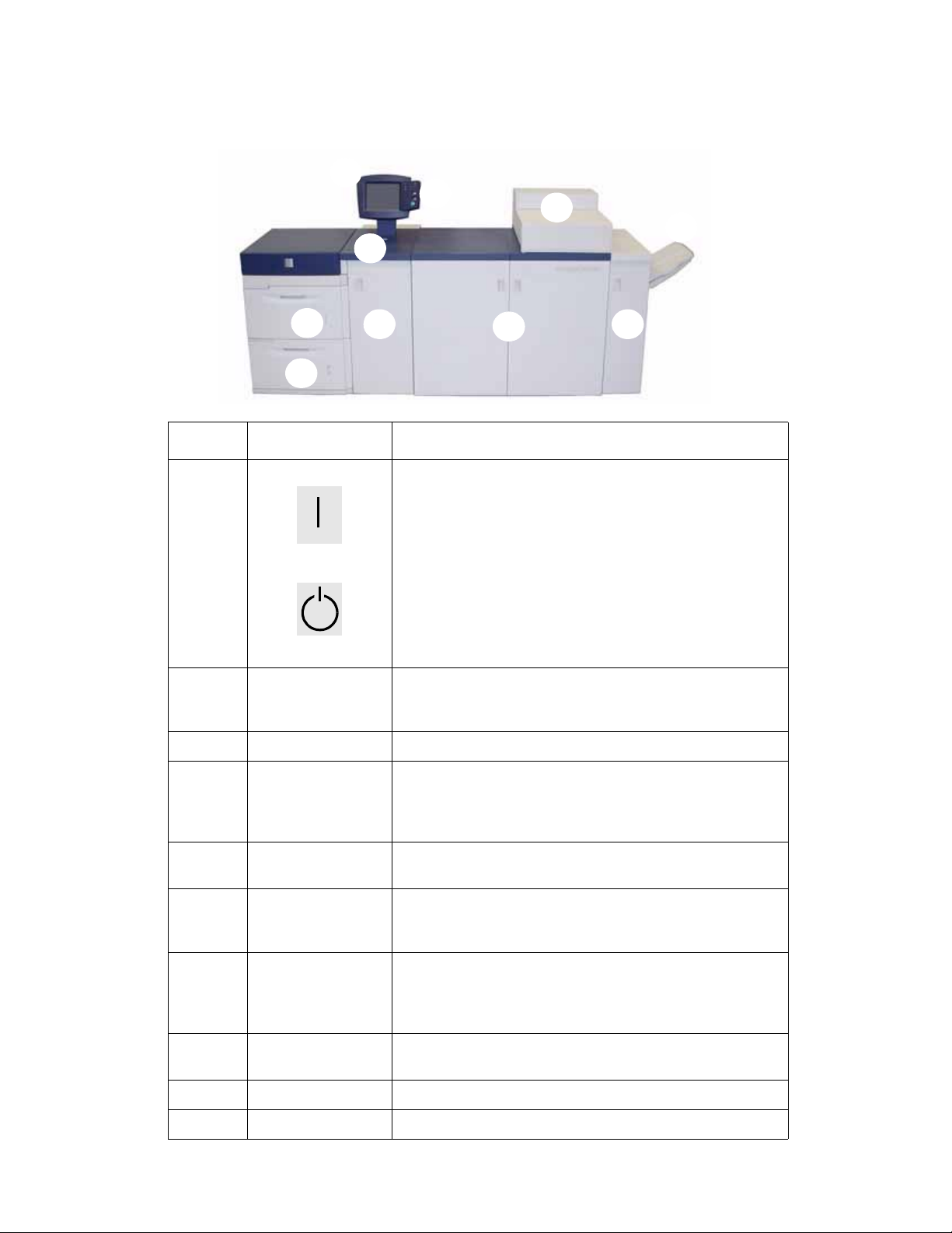
Major Components
2
3
1
DocuColor 7002/8002
4
5
10
8
7
6
9
Number Part Description
1On/Off
On
Off
2 User Interface The User Interface contains two components: the Control Panel
3 Control Panel Allows keypad selection of features.
Press the Power Switch to the On position to power on the digital
press.
A screen message advises of a short wait while the Fuser warms
up and the digital press runs a system check.
Press the Power Switch to the Off position to power off the digital
press.
Allow the digital press to remain off for a minimum of twenty
seconds before switching the power on again.
and the Touch Screen and is used for messaging and to select
settings.
4Dry Ink/Toner
Compartment
5 Offset Catch Tray
(OCT)
6 Exit Module Contains the decurler and the inverter. The decurler removes any
7 Right/Left Front
Doors
8 Transport Module The Transport Module carries the paper from the paper trays to
9 Paper Tray 2 Holds 2000 sheets of 24 lb. (90 g/m
10 Paper Tray 1 Holds 2000 sheets of 24 lb. (90 g/m
1-2 User Guide
Contains the Dry Ink/Toner cartridges. The cartridge colors from
left to right, are black, cyan, magenta, and yellow. Refer to the
Maintenance Chapter of this manual for instructions on
changing the cartridges.
Receives completed print job. Sets are offset for easy separation.
Maximum capacity is 500 sheets of 24 lb. (90 g/m
curl from the printed page. The inverter is used when duplexing
or face down output is selected.
Houses the image transfer system for simplex and duplex
printing. Open to clear jams in the paper path in the Printing
Module and at the Fuser. Follow the instructions precisely for
clearing a jam in the Fuser.
the upper paper path of the digital press.
2
) paper.
2
) paper.
2
) paper.
Page 9
DocuColor 7002/8002
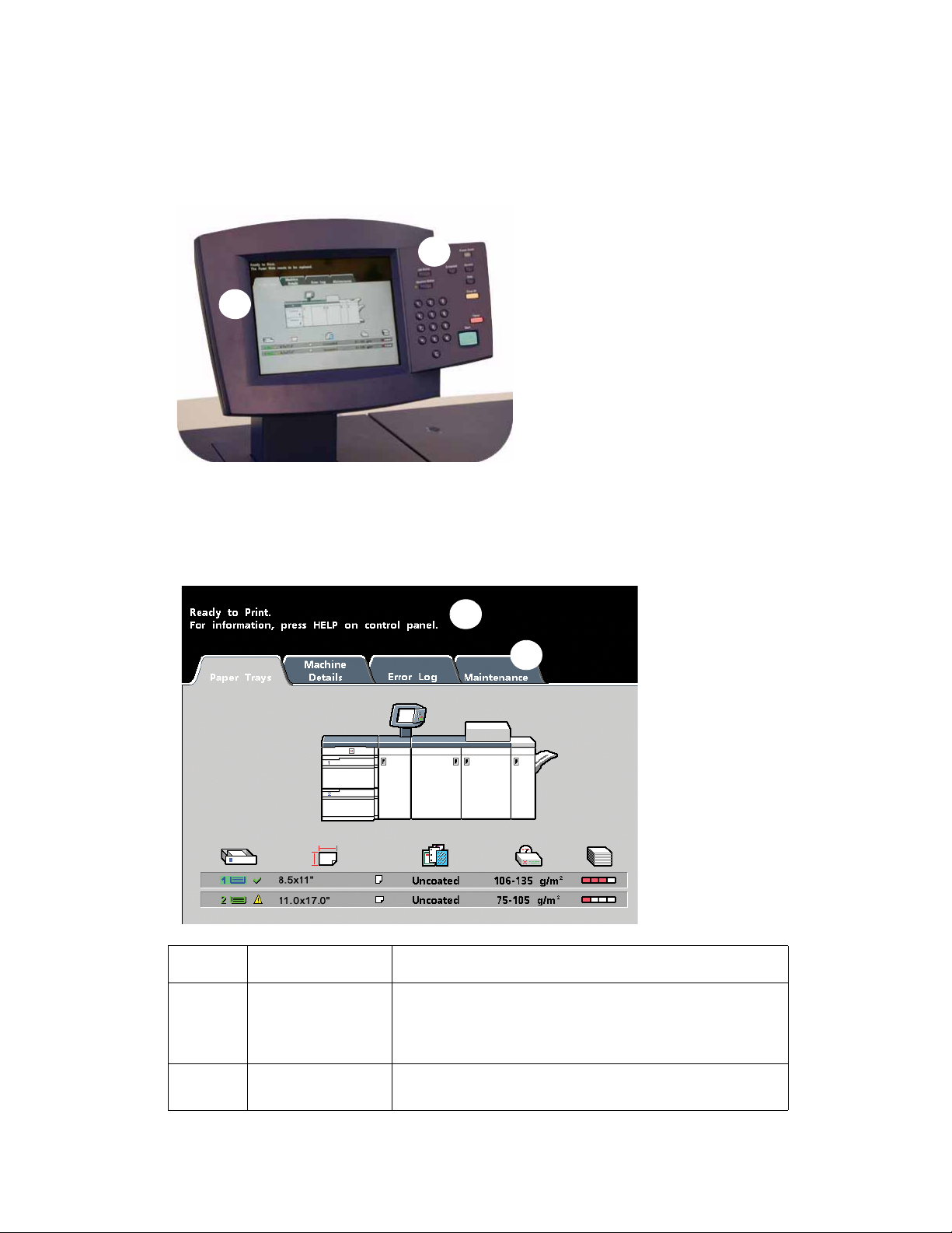
User Interface (UI)
The User Interface (UI) displays messages that indicate the status of the digital press during
idle, run, or fault conditions.
2
1
1. Touch Screen
2. Control Panel
Touch Screen
1
2
Number Part Description
1 Message Area The message area at the top of the UI displays messages
concerning the digital press status, programming conflicts,
or errors. Messages may also provide instructions for the
operator.
2Tabs and FunctionsSome UI screens display tabs containing various
selectable options.
User Guide 1-3
Page 10
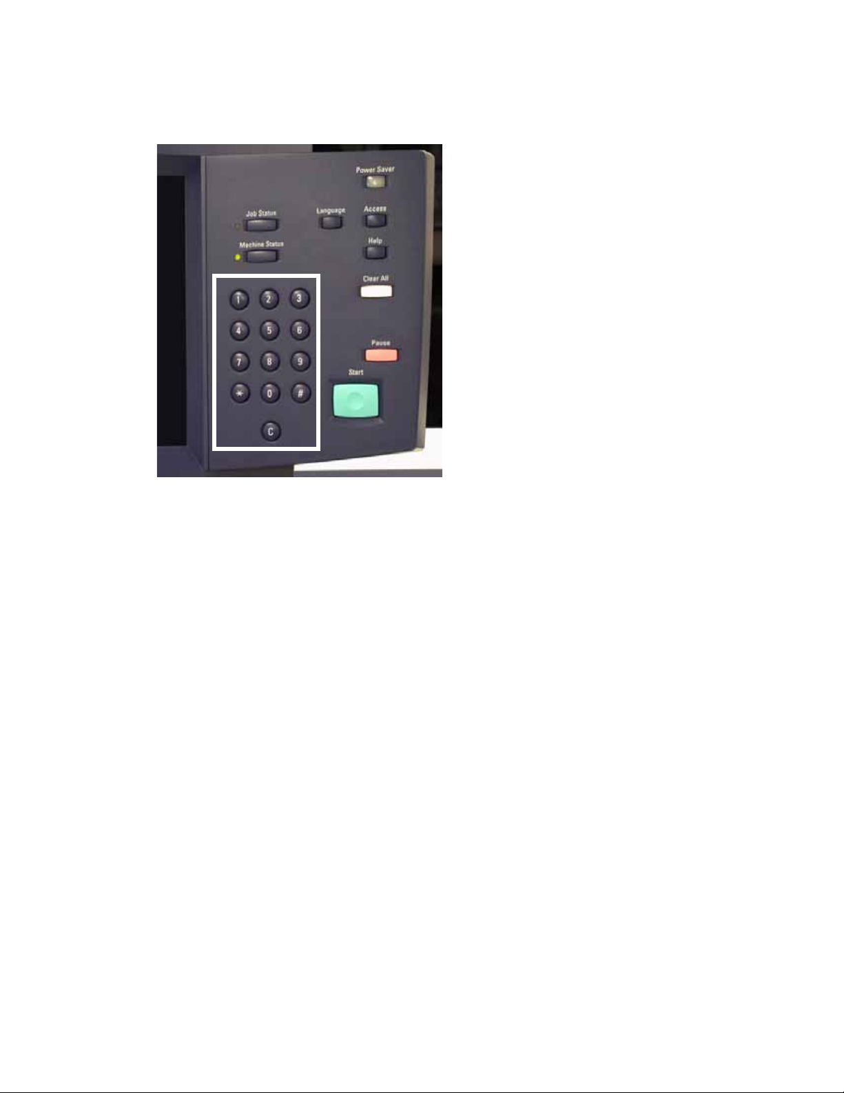
Control Panel
DocuColor 7002/8002
Keypad
Use the numeric keypad to enter your password for access to Tools Mode. Use the keypad for
certain Tools Mode features. The keypad is also used by the service representative in the
diagnostics mode.
1-4 User Guide
Page 11

DocuColor 7002/8002
Your digital press has one of two Control Panels: a Control Panel with words or one with
international symbols. See the following for button functions.
Power Saver
Lights up when the digital press is in Sleep Mode. Press to return to Standby Mode.
Job Status
Displays a list on the UI of the current jobs and their status. You can hold, release,
promote, delete, and see the options selected for each job.
Language
Allows you to select one of two languages.
Access
Allows access to the password-protected Tools Mode and the Auditron Mode.
Machine Status
Accesses the Paper Tray, Machine Details, Error Log, and Maintenance screens.
Machine Status is where you find the serial number for the digital press, the customer
support phone numbers, and the meters that show the count for color, black and white,
color large size, and total output.
Help
Displays additional information useful in completing a task.
Clear All
The Clear All button is used in the Tools Mode for clearing certain selections or
settings. Pause
Pause
Press the Pause button to pause printing in order to perform certain maintenance
procedures such as changing the dry ink/toner cartridge. You must press Pause again to
resume printing.
Start
The Start button is used in the Tools Mode for certain settings. It is also used by the
service representative in the diagnostics mode.
User Guide 1-5
Page 12
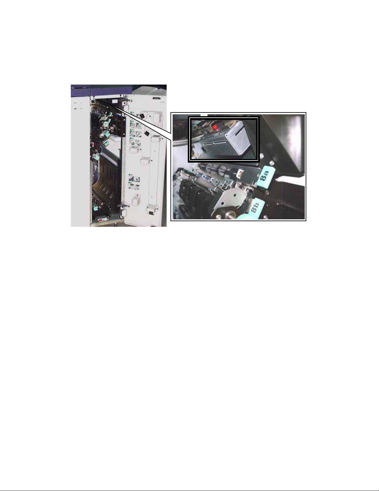
DocuColor 7002/8002
Internal Spectrophotometer
Your digital press includes an internal Spectrophotometer, which is located in area 8A of the Exit
Module.
The internal Spectrophotometer is sometimes referred to as the “Inline Sensor” (ILS). The
internal Spectrophotometer provides the customer with an internal calibration internal tool that
ensures the digital press is ready to print colors. This feature provides the customer with the
ability to calibrate the digital press from the Color Server without manually feeding calibration
charts (also known as “calibration targets”). The customer can use this either in the present, or
program it to calibrate at a designated time. It also allows the customer to maintain tighter
control over the output of thier system.
Note
Refer to your Color Server’s user documentation when performing the calibration workflow of
the Color Server in conjunction with the digital press.
1-6 User Guide
Page 13
DocuColor 7002/8002
Job Management
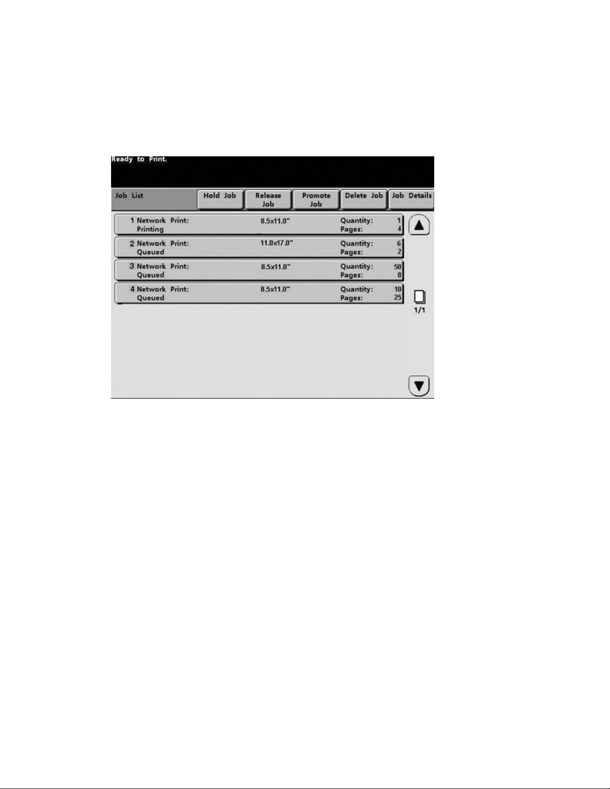
Job Status
When you press the Job Status button, the Job Status screen is displayed.
The Job Status screen includes Job Type, Current Status, Paper Size, Output Quantity (refers to
the output in sheets for a single page job and in sets or stacks for a multiple page job), and total
Number of Pages.
Jobs are numbered in the order they are received for processing.
Review the information that is provided for controlling the print workflow;
• Job List - Shows all jobs submitted to the digital press.
• Hold Job - Holds a job in the print queue until released.
• Release Job - Releases a Hold Job to be printed.
• Promote Job - Enables a job to be moved in front of other jobs in the queue.
• Delete Job - Deletes a selected job.
• Job Details - Shows the programmed options for a selected job.
• Up/Down Arrows - Enables scrolling through job list.
For more information about help, refer to Machine Details located in the Appendix.
User Guide 1-7
Page 14
Optional accessories
Optional feeding accessories
DocuColor 7002/8002
Feeding accessory Description
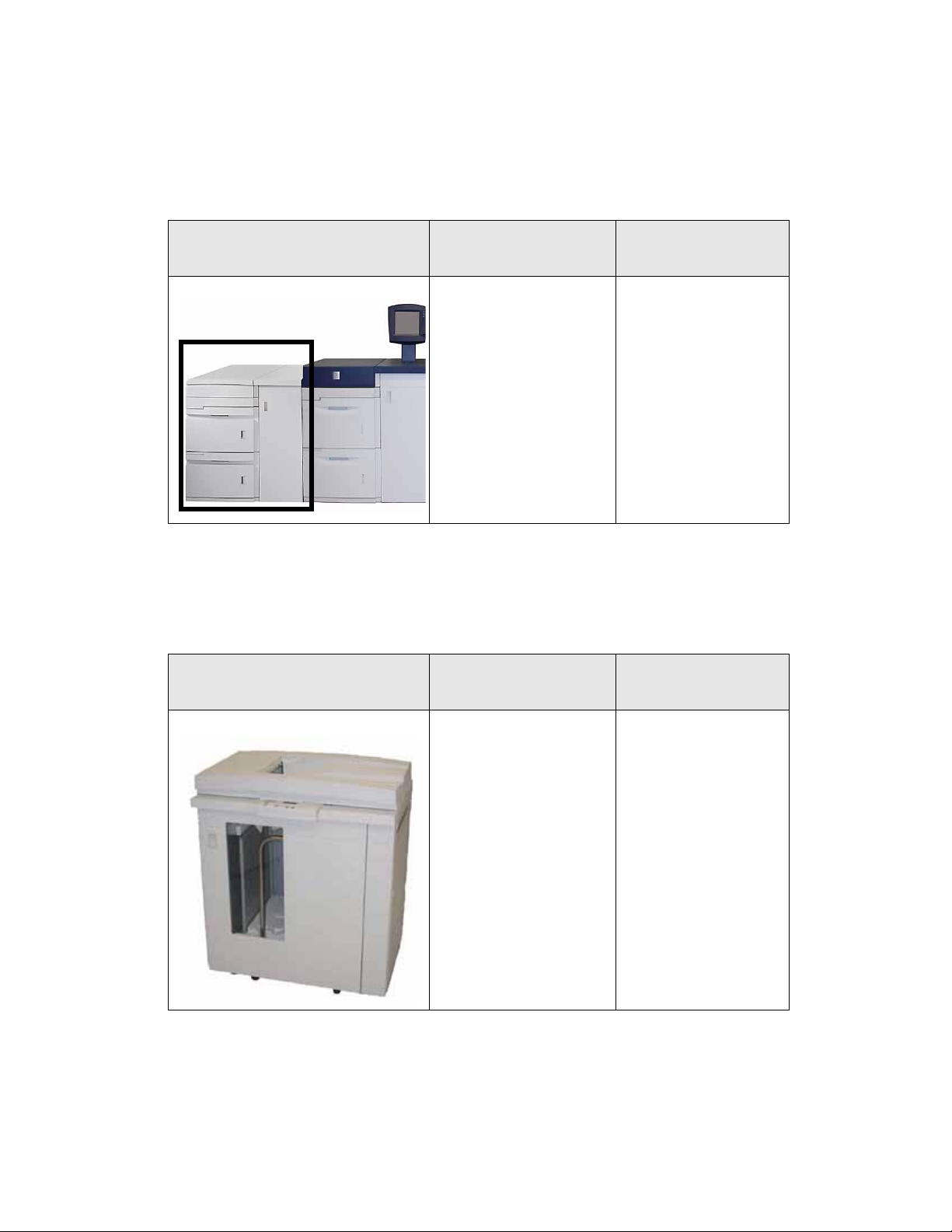
Trays 3 and 4 (Second Feeder Module)) The two-tray Second Feeder
Module (SFM), also referred
to as Trays 3 and 4, provides
an extra 4,000 sheet
capacity of either 8.5 x 11 in.
or A4 paper. Each drawer
holds 2,000 sheets (16 lb.
Bond to 80 lb. Cover/52 gsm
to 216 gsm).
Optional finishing accessories
Finishing accessory Description
Where to find
information
Information on Trays 2
and 4) can be found in this
user guide. Refer to the
following chapters for
more information:
• Loading Paper
• How to Clear Jams
• Optional Accessories
• Specifications
•Appendix
Where to find
information
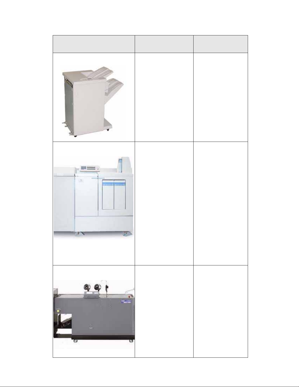
High Capacity Stacker (HCS) The HCS is an optional
finishing device that
provides stacking and
offsetting capabilities for
output to a Stacker Tray. The
HCS80 connects to the right
side of the digital press
replaces the Offset Catch
Tray (OCT).
Information on the High
Capacity Stacker (HCS) be
found in this user guide.
Refer to the following
chapters for more
information:
• How to Clear Jams
• Optional Accessories
•Basic
Troubleshooting
• Specifications
•Appendix
1-8 User Guide
Page 15
DocuColor 7002/8002
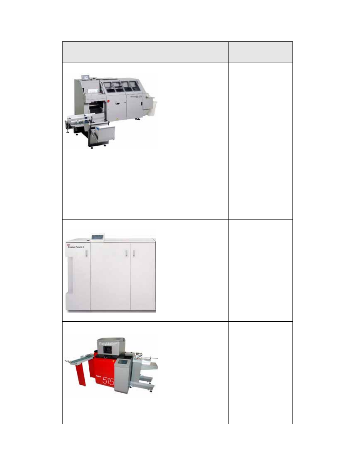
Finishing accessory Description
High Capacity Stacker/Stapler (HCSS) or
Common Stacker/Stapler (CSS)
Xerox Document Binder 120-D (DB120D)
™
The HCSS and CSS are
optional finishing devices
(referred to as finishers) that
provide stacking with offset
and single or dual stapling
output capabilities.
The Document Binder 120-D
is a third-party, Document
Finishing Architecture (DFA)
device that uses a unique
perfect binding technology
combined with pre-formed
covers to create a high
quality professionally bound
document.
The Document Binder120-D
provides:
• Inline thermal binder
• Binds 8.5 x 11" and A4
documents up to 120
pages in a variety of
eye-catching preformed or custom
covers
• Requires Xerox High
Capacity Stacker 80 to
connect inline finishing
devices
Where to find
information
Information on the HCSS
and CSS be found in this
user guide. Refer to the
following chapters for
more information:
• How to Clear Jams
• Optional Accessories
•Basic
Troubleshooting
• Specifications
•Appendix
Information on the
Document Binder 120-D
can be found in the
Finishing Solutions
Guide; contact your Xerox
sales representative for
more information.
Duplo SCC Nearline Booklet Maker
™
System
User Guide 1-9
The Duplo SCC Nearline
Booklet Maker is a thirdparty device that provides:
• Nearline booklet maker
with stitch, fold, and
fac e t rim featu re s
• Automatic set-up and
bar code reader options
Information on the Duplo
SCC Nearline Booklet
Maker can be found in the
Finishing Solutions
Guide; contact your Xerox
sales representative for
more information.
Page 16
DocuColor 7002/8002
Finishing accessory Description
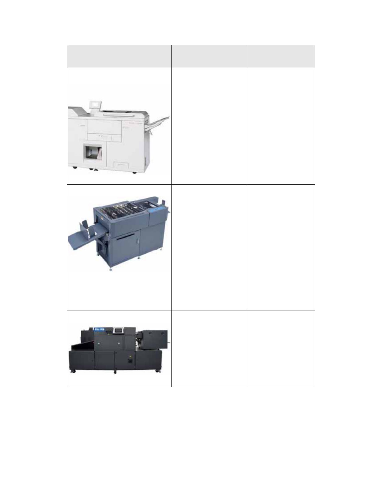
Horizon ColorWorks/ColorWorks Pro
Booklet Maker
Duplo DC-645 Slitter-Cutter-Creaser
™
The Horizon ColorWorks or
ColorWorks Pro Booklet
Maker is a third-party,
Document Finishing
Architecture (DFA) device
that provides inline booklet
maker with scoring, bleed
trim, face trim, stacking,
folding, and stapling
featur es.
The ColorWorks Pro version
provides additional scoring,
full-bleed trim, and covers
feed.
™ The Duplo DC-645 Slitter-
Cutter-Creaser is a thirdparty device that provides:
• Cutting and creasing
operations in a single
pass, plus it has the
unique Duplo feature of
being able to
automatically adjust
and compensate for
image drift.
• The ability to manage
heavier media and
larger sheet sizes at
higher finishing speeds.
Note
This is an offline device.
Where to find
information
Information on the
Horizon ColorWorks
Booklet Maker c can be
found in the Finishing
Solutions Guide; contact
your Xerox sales
representative for more
information.
Information on the Duplo
DC-645 Slitter-CutterCreaser can be found in
the Finishing Solutions
Guide; contact your Xerox
sales representative for
more information.
Duplo Ultra 145A UV Offline Coater
™ The Duplo Ultra 145A UV
Offline Coater is a thirdparty device that provides
high quality, cost-effective
ultraviolet coating on
documents.
Note
This is an offline device.
1-10 User Guide
Information on the Duplo
Ultra 145A UV Offline
Coater can be found in the
Finishing Solutions
Guide; contact your Xerox
sales representative for
more information.
Page 17
DocuColor 7002/8002
Finishing accessory Description
Horizon Perfect Binder BQ-270x
™ The Horizon Perfect Binder
BQ-270xis a third-party
device that provides:
• High-quality production
perfect binding with
fully automated
operation and pushbutton simplicity.
• Intelligent touch-screen
control console
• Newly-developed
adhesive application
and side-gluing system
• Automatic air-suction
cover feeding with inline scoring
• Job programming and
• Same-location loading
and unloading for
easier single-person
operation
Note
This is an offline device.
®
Fusion Punch II ™ The GBC Fusion Punch II is a
GBC
third-party, Document
Finishing Architecture (DFA)
device that provides in-line
printer punching that
combines printing and
punching into one step.
Single sheets are punched
and emerge ready to be
finished into lay flat
documents
Where to find
information
Information on the
Horizon Perfect Binder BQ270x can be found in the
Finishing Solutions
Guide; contact your Xerox
sales representative for
more information..
Information on the GBC
Fusion Punch II can be
found in the Finishing
Solutions Guide; contact
your Xerox sales
representative for more
information..
Kern 515 EasyMailer
User Guide 1-11
®
The Kern 515 EasyMailer is a
third-party device that
allows for 11” x 17” (A3) or
8.5” x 11” (A4) cut sheet
processing delivering a
personalized envelope
wrapped around an equally
personalized letter.
Information on the Kern
515 EasyMailer can be
found in the Finishing
Solutions Guide; contact
your Xerox sales
representative for more
information..
Page 18

DocuColor 7002/8002
1-12 User Guide
Page 19

Where to Find Help
1-800 Telephone numbers
For system support, user help, and service support, call the appropriate number:
US: 1-800-821-2797 (Includes TTY Support)
Canada: 1-800-939-3769
Xerox also provides web-based customer support. Go to:
www.xerox.com/eSupportCentre
2
User Guide 2-1
Page 20
Where to Find Help DocuColor 7002/8002
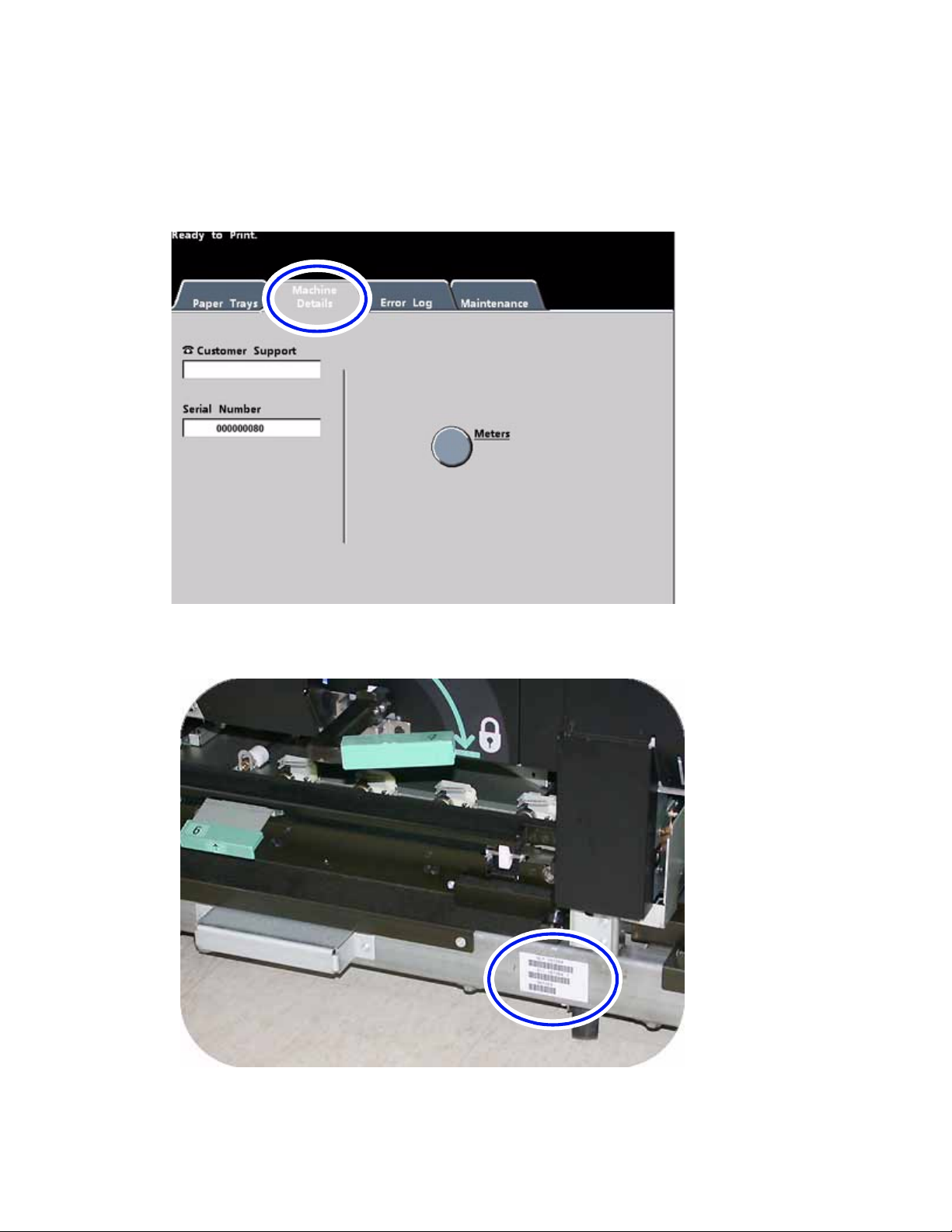
How to find the machine serial number
You can find the serial number two places:
1. Press the Machine Status button on the Control Panel and then press the Machine Details
tab, or
2. Open the front doors to locate the serial number plate on the frame.
2-2 User Guide
Page 21
DocuColor 7002/8002 Where to Find Help
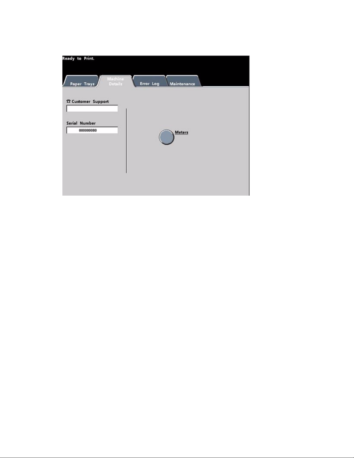
How to read the Billing Meters
1. Press the Machine Status button on the Control Panel.
2. Press the Machine Details Tab.
3. Press the Meters button.
User Guide 2-3
Page 22
Where to Find Help DocuColor 7002/8002
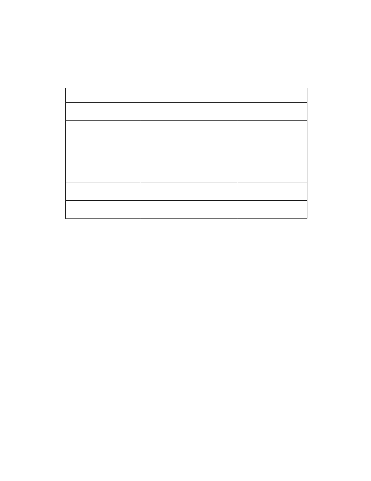
Reference Documents
There are additional reference documents available to you that provide more detailed
information. Refer to the list below for the title, description and the location of the document.
Document Description Location
System Administration Guide Provides detailed descriptions of System
Administrator functions
Decurler Adjustment An adjustment to help correct decurling
problems
Specialty Media Guide Provides specialty media
recommendations, hints and tips
regarding best printing practices.
Chapter 3 Loading Paper Quick reference to loading paper Found on the Customer
Corotron Test Test opattern used to help determine
image quality problem
Safety Guide All the safety inform ation associated
with this machine
Found on the Customer
Documentation CD
Found on the Customer
Documentation CD
Found on the Customer
Documentation CD
Documentation CD
Found on the Customer
Documentation CD
Found on the Customer
Documentation CD
2-4 User Guide
Page 23
Loading Paper
Loading paper (Trays 1-4)
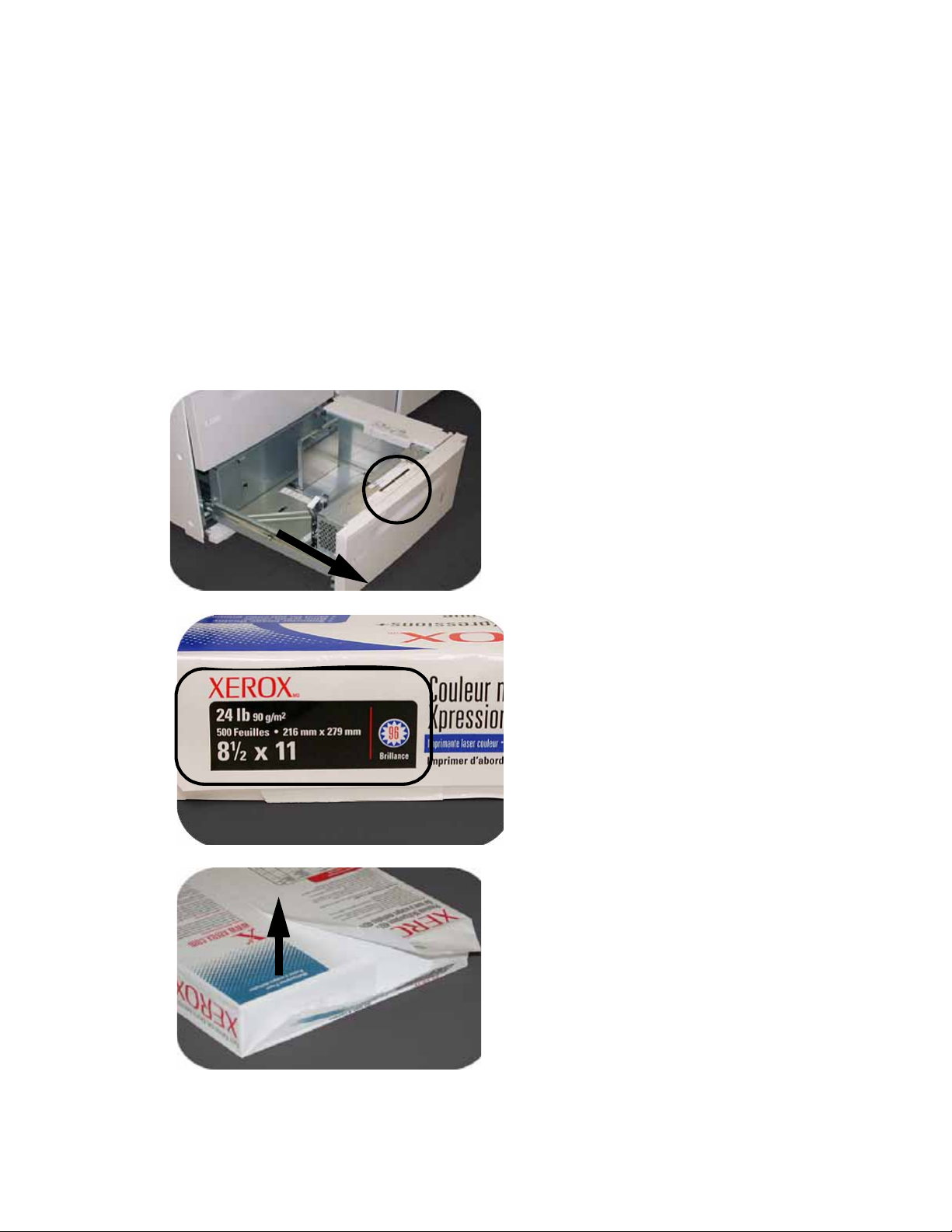
1. Lift the handle and pull out the paper tray.
2. Select the appropriate paper stock for your print job.
3
3. Open the ream of paper seam side up and place it in the tray.
User Guide 3-1
Page 24
Loading Paper DocuColor 7002/8002
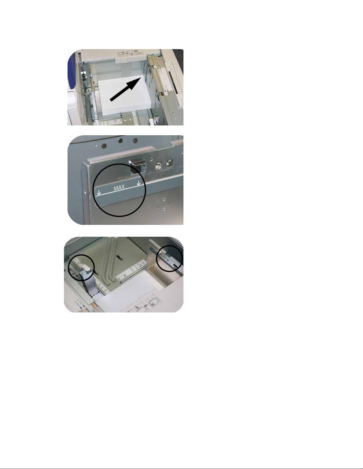
4. Place the paper in the front right corner of the tray.
5. Do Not exceed the “Max” fill line.
6. Squeeze the green levers, and slide the Paper Guides until they touch the side of the paper.
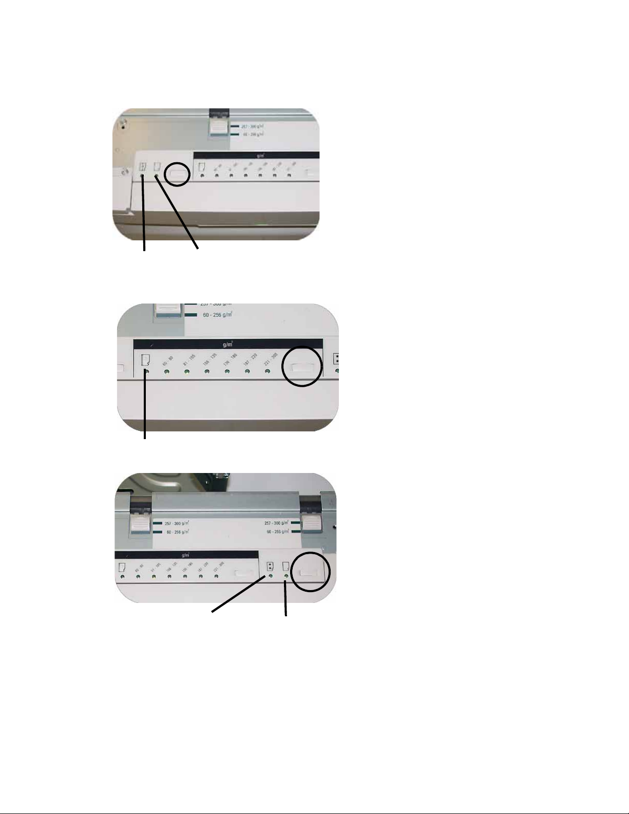
7. Press the button to select Non-Standard or Standard at the front of the tray. The green
light will indicate your selection.
3-2 User Guide
Page 25
DocuColor 7002/8002 Loading Paper
Non-standard size paper is any paper for which there is no paper guide setting within the
minimum and maximum sizes for the trays: 7.16 to 12.6 inch Long Edge Feed (LEF) or 7.16
to 19.2 inch SEF (182 - 320 mm LEF or 182 x 488 mm Short Edge Feed (SEF)
Non-Standard
Standard
8. Press the button to select Transparency or the appropriate paper weight. The green light
will indicate your selection.
Transparency
9. Press the button to select Coated or Uncoated. The green light will indicate your selection.
Coated
User Guide 3-3
Uncoated
Page 26
Loading Paper DocuColor 7002/8002
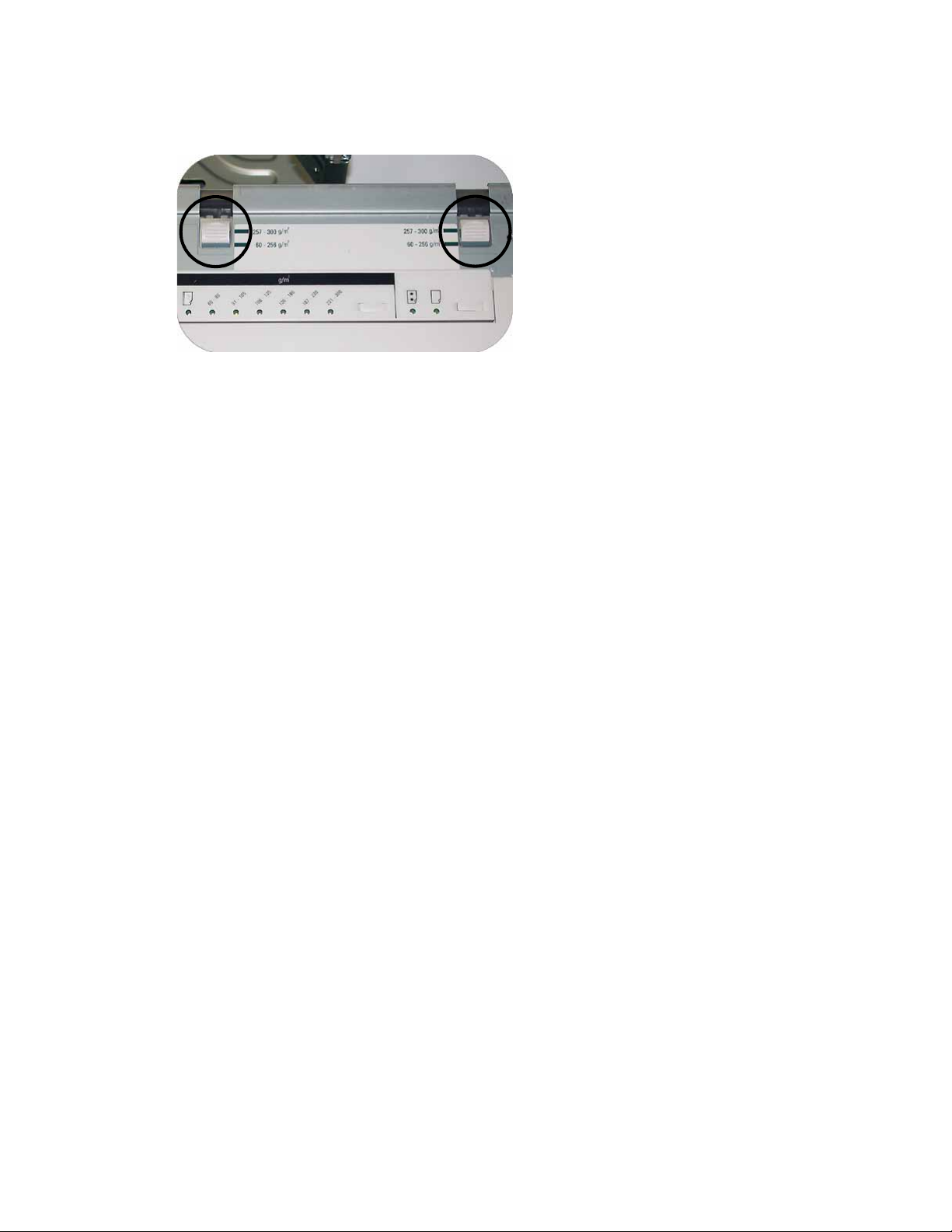
10. Select the position of the Paper Tray Blowers to match the weight of the paper stock in the
tray.
11. Slide the tray back into the machine until it locks into place.
Paper Tray Guidelines
For best results, remember the following:
• Do not store reams of paper in any of the trays.
• Do not use wrinkled, torn, curled, or folded paper.
• Do not mix sizes or weights of paper in a paper tray.
3-4 User Guide
Page 27

How to Clear Jams
4
Printer jam clearance
If a jam occurs, the digital press stops printing and a message is displayed on the User Interface
(UI). Follow all instructions displayed completely
additional information to resolve the problem.
If power is interrupted during the printing process, it is imperative that you clear areas behind
the Right and Left Front Doors last
Paper tray jams
CAUTION
Be careful of the Feed Heads and the Feed Rolls. They can be damaged with rough treatment.
. Clear all other jam areas first.
and in sequence. Refer to this chapter for
CAUTION
If you hear paper tearing, stop opening the tray. Open the door of the Transport Module or the
Second Feeder Module (SFM) Transport Area and clear the paper from the Transport Module
before attempting to open the tray again.
1. Open the tray with the jam.
2. Carefully remove all jammed paper.
3. Use the UI to determine if further jams exist and clear those areas.
User Guide 4-1
Page 28
How to Clear Jams DocuColor 7002/8002
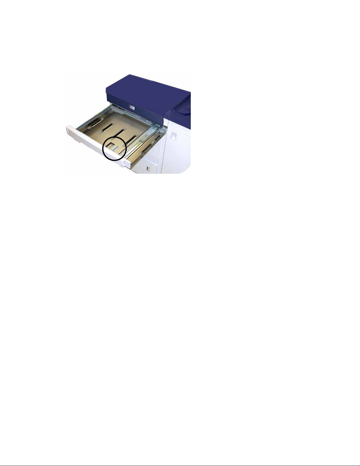
Upper Transport Area
Jams occur in this area only when the Second Feeder Module containing Trays 3 and 4 is
connected.
1. Pull out the Transport Area drawer above Tray 1.
2. Lift up the handle.
3. Remove all jammed paper.
4. Return the drawer to its original position.
5. Follow the instructions on the UI to clear other areas or to resume your print job.
4-2 User Guide
Page 29
DocuColor 7002/8002 How to Clear Jams
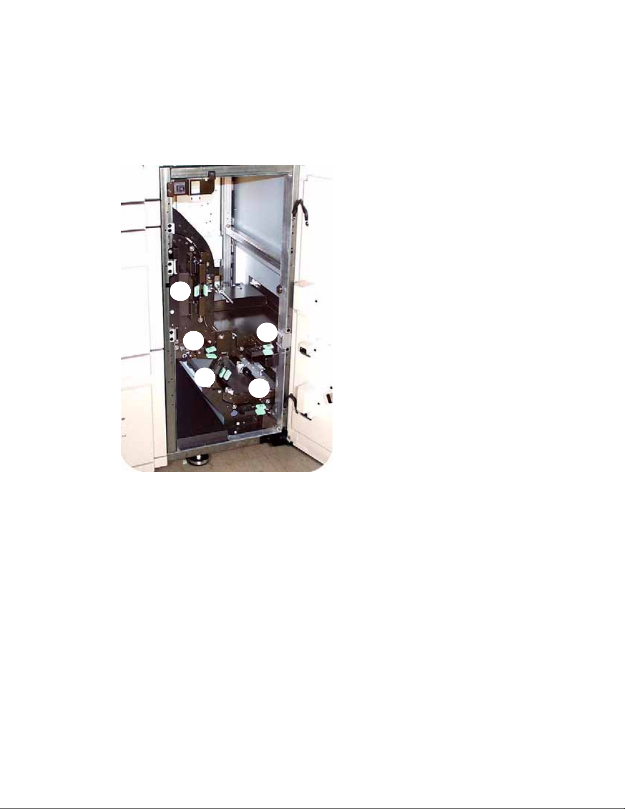
Transport Module
Note
Refer to the video located on the Customer Documentation CD as needed.
Open the areas in the Transport Module indicated on the UI. Carefully remove all jammed
paper.
3a
7c
3b
7b
7a
1. Open the Transport Module door.
2. Grasp the green handles 3a, squeeze and move it to the right.
3. Carefully remove all jammed paper.
4. Reposition handles 3a.
5. Lift up green handles 3b.
6. Carefully remove all jammed paper and return handles 3b to the original position.
7. Follow the UI messages and, if required, lift handles 7a and remove all jammed paper.
Return handles 7a to the original position.
8. Squeeze handles 7b and lower to the right. Remove all jammed paper. Return handles 7b
to the original position.
9. Squeeze handles 7c and lower to the left. Remove all jammed paper. Return handles 7c to
the original position.
10. Close the Transport Module door.
11. Follow the instructions on the UI to restart your print job.
User Guide 4-3
Page 30
How to Clear Jams DocuColor 7002/8002
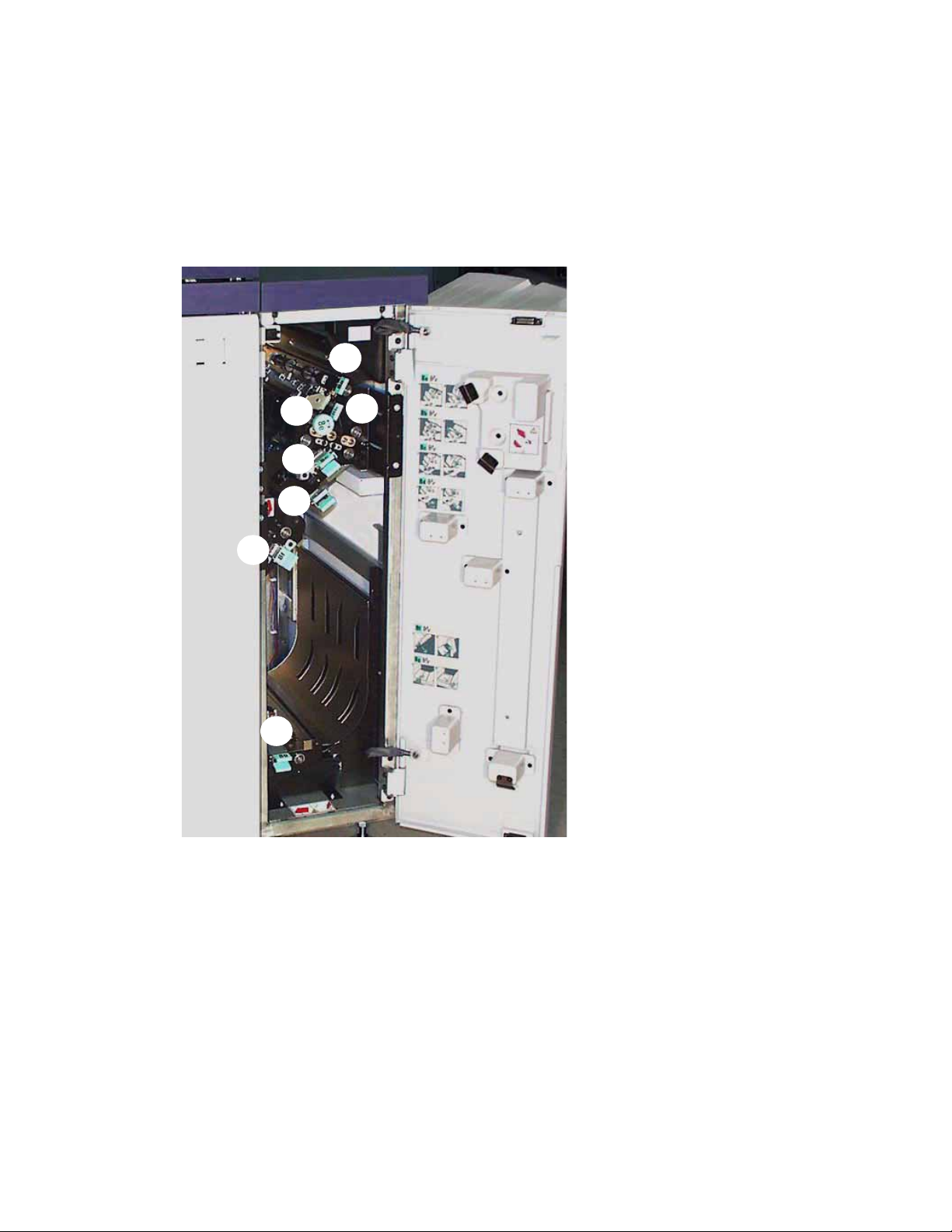
Exit Module
Note
Refer to the video located on the Customer Documentation CD as needed.
Follow the instructions on the UI to clear jams from all the areas indicated in the Exit Module.
Follow the instructions on the UI to restart your print job.
8a
8f
8g
8e
8c
8d
8b
4-4 User Guide
Page 31

DocuColor 7002/8002 How to Clear Jams
Right/Left Door Paper Path
WARNING
Be careful when clearing jams in the Fuser Area. The Fuser is extremely hot and will cause injury.
Note
Refer to the video located on the Customer Documentation CD as needed.
Tip
Always follow the instructions on the UI to locate and clear jams.
Note
It is imperative that you clear all other jam areas before you open and clear the Right and Left
Front Door areas.
1. Open the Right and Left Front Doors when directed to by a UI message.
2. Grasp handle 4 and move it in the direction of the arrow.
3. Slowly pull out the Paper Transport module until it stops.
4a
4b
4. Lift handle 4a and carefully remove all jammed paper, ensuring that all pieces are removed
if the paper is torn. Turn the green handle 4b to free any paper that is caught.
5. Reposition green handle 4a.
User Guide 4-5
Page 32

How to Clear Jams DocuColor 7002/8002
6. The Fuser area is on the right hand side of the Paper Transport module. Lift handle 4c on
the right hand side and pull to open.
4d
4e
4c
7. Lift up handle 4d until it stops and clear any jammed paper. Rotate knob 4e in the direction
of the arrow on the knob to clear any paper that is caught.
Occasionally a sheet of paper wraps around the heat roll. (The heat roll is visible when
handle 4d is up). DO NOT attempt to remove this sheet of paper because the stripper
fingers may be damaged if you attempt this procedure. Call your Xerox service
representative to remove this piece of paper.
8. Reposition green handle 4d and close area 4c. Ensure these are firmly in place.
9. Grasp handle 4 and slowly push in the Paper Transport until it stops. Turn the handle in the
direction of the arrow to lock the module in place.
10. Close the Right and Left Front Doors.
11. Follow the instructions on the UI to restart your print job.
4-6 User Guide
Page 33

DocuColor 7002/8002 How to Clear Jams
Jam Clearance with 2-Sided Printing
When printing 2-Sided output, the UI will direct you to clear the following areas if a jam occurs.
1. Open the Right and Left Front Doors when directed to by a UI message.
2. Lift handles 5 and 6 and clear any paper in the areas.
6
CAUTION
Paper can rip if not pushed back before removing it from under the lip of this area
3. Push the paper back until you see the front edge, then remove the paper.
4. Reposition handles 5 and 6 by closing firmly.
5. Close the Right and Left Front Doors.
6. Follow the instructions on the UI to restart your print job.
5
.
User Guide 4-7
Page 34

How to Clear Jams DocuColor 7002/8002
High Capacity Stacker 80 (HCS80)
A paper jam in the HCS80 will be indicated by a message on the digital press UI. Follow the
instructions displayed. The image on the HCS80 Control Panel will flash showing the area where
the jam is located.
Bypass Area
Perform the following steps to clear the HCS80 jam in the Bypass area and resume printing.
1. Remove any paper from the Top Tray.
2. Lift the HCS80 Top C over.
3. Lift the green handle, or handles, indicated on the UI and remove all paper in the Bypass
area. Remove paper only from the areas indicated.
4. Close each green handle.
5. Close the HCS80 Top C o v e r .
6. If the UI indicates there is a jam in the digital press, follow the instructions on the screen to
remove any paper in the area indicates. Refer to the Jam Clearance section in the Problem
Solving chapter in this manual.
7. Follow the instructions displayed on the digital press UI to resume printing.
4-8 User Guide
Page 35

DocuColor 7002/8002 How to Clear Jams
High Capacity Stacker/Stapler (HCSS) and Commn Stacker/Stapler (CSS)
A paper jam in the finishers is indicated by a message on the digital press Touch Screen. The
finisher Control Panel display illuminates the area where the jam has occurred.
Read the following steps for more information on how to clear a jam.
1
2
3
1. Open the finisher Front Door. There are three possible jam areas. Handle 1 moves down,
handle 2 moves to the right, and handle 3 moves up.
2. Remove all jammed paper only from the area indicated on the Touch Screen and the
finisher Control Panel Display. Do not remove paper from any other areas.
3. Reposition the handle.
4. Close the finisher Front Door.
5. Follow any instructions on the Touch Screen to restart your print job.
User Guide 4-9
Page 36

How to Clear Jams DocuColor 7002/8002
4-10 User Guide
Page 37

How to adjust Paper
5
Curl
Paper Curl
When paper is exposed to heat, the paper loses moisture and curls toward the heat source. High
coverage jobs tend to curl more due to the toner plastification effect on the paper surface. The
system tries to reduce this by using mechanical devices within the paper path called decurlers.
Your system has been designed with an automatic curl control system that uses information
such as: the amount of coverage on the page, paper weight, whether the paper is coated or
uncoated, and the current humidity and temperature to determine the amount of pressure
needed at the different decurlers to reduce output curl.
If the curl is unacceptable, you can change the setting.
To change the paper curl setting, you must enter the Tools mode.
User Guide 5-1
Page 38

How to adjust Paper Curl DocuColor 7002/8002
Tool Mode
1. To enter Tools Mode, press the Access button on the Control Panel. The Access Password
Screen appears.
2. Use the keypad to enter your password.
3. Press the Enter button.
4. Press the Too l s Pat h way button to enter the Tools Mode.
5. Press the Machine Default 2 Tab and then press the Decurler Setup button.
5-2 User Guide
Page 39

DocuColor 7002/8002 How to adjust Paper Curl
6. When the Decurler Setup screen appears, enter the paper tray number you are using,
coated or non-coated and the paper weight.
7. The default curl setting (Paper Type) for the selected paper will be displayed (A-D). Type A is
selected in the example screen.
8. Select a different setting (A-D) and run the job again. Some experimentation may be
needed to find the correct setting.
Note
If you are not able to find an acceptable setting that minimizes curl, refer to the document
entitled DocuColor 7002/8002 Decurler Adjustment
.
User Guide 5-3
Page 40

How to adjust Paper Curl DocuColor 7002/8002
5-4 User Guide
Page 41

How to Run Tabs
Ta b s
Tabbed Inserts can be loaded into the paper trays as Non-Standard paper.
6
1. Load 9 X 11 inch tab stock (228 x 279 mm) in the paper tray with the tabs with the short
edge of the tabs in the lead edge position.
Note
If a jam ocurrs, there is no recovery procedure. You will need to manually recover.
2. Press the button to select the appropriate tab weight. The green light will indicate your
selection.
User Guide 6-1
Page 42

How to Run Tabs DocuColor 7002/8002
3. Press the button to select Non Standard or Standard at the front of the tray. The green
light will indicate your selection.
Standard
Non-standard
4. Press the button to select Coated or Uncoated. The green light will indicate your selection.
Coated
Uncoated
5. Enter Tools Mode: Press the Access button on the Control Panel. The Access Password
Screen appears.
6-2 User Guide
Page 43

DocuColor 7002/8002 How to Run Tabs
6. Use the keypad to enter your password.
7. Press the Enter button.
8. Press the Too l s Pat h way button to enter the Tools Mode.
9. Press the Non-Standard Paper Size button.
User Guide 6-3
Page 44

How to Run Tabs DocuColor 7002/8002
10. Select the appropriate Paper Tray and enter 11 in the X Axis box and 9 in the Y Axis box by
using the up and down arrow buttons.
11. Run the tab job.
6-4 User Guide
Page 45

Productivity Settings
7
Overview
The productivity of the digital press relates to the continuous speed of the media output as
measured in prints per minute (ppm). The continuous speed is dependent on paper size, paper
weight, and fuser temperature. Use this productivity setting to optimize the throughput speed
for the type of paper you run most frequently.
Productivity Setting options are shown and explained in the illustration:
• Single Paper Weight:
This setting optimizes the throughput speed for light weight or heavy weight papers, according
to the weight range that is set in the paper tray.
•Mixed Paper Weight:
This setting optimizes the throughput speed of print jobs that contain mixed media weights
from different paper trays.
• All Weights Rated Speed:
This setting runs all jobs at the rated speed regardless of the paper weight. Gloss level may
appear lower on heavier weight media. If a higher level of gloss is required, run the job at the
Single Paper Weight setting.
User Guide 7-1
Page 46

Productivity Settings DocuColor 7002/8002
Changing the Productivity Setting
1. Enter Tools Mode: Press the Access button on the Control Panel. The Access Password
Screen appears.
2. Use the keypad to enter your password.
3. Press the Enter button.
4. Press the Too l s Pat h way button to enter the Tools Mode.
5. Press the Productivity Setting button.
7-2 User Guide
Page 47

DocuColor 7002/8002 Productivity Settings
6. Select the desired productivity setting.
7. Select Close.
All jobs will run at the selected productivity setting until changed in Tools Mode.
User Guide 7-3
Page 48

Productivity Settings DocuColor 7002/8002
7-4 User Guide
Page 49

Optional Accessories
The accessories included in this module are:
• Paper Trays 3 and 4
• High Capacity Stacker 80 (HCS80)
• High Capacity Stacker Stapler 80 (HCSS80)/Common Stacker Stapler (CSS)
8
Trays 3 and 4 (Second Feeder Module)
Tray 3
Tray 4
The Second Feeder Module (SFM) is an optional feeding device that contains Trays 3 and 4. This
module holds the same number and types of Media as Trays 1 and 2.
The specifications and operation are identical to the First Feeder Module. (Trays 1 and 2).
User Guide 8-1
Page 50

Optional Accessories DocuColor 7002/8002
High Capacity Stacker 80 (HCS80)
Control Panel
Stacker Tray/Cart
The HCS80 is an optional finishing device that provides stacking and offsetting capabilities for
output to a Stacker Tray. The HCS80 connects to the right side of the digital press replaces the
Offset Catch Tray (OCT).
Top Tray
Bypass
Top Tra y
Sheets are transported to the Top Tray:
• When sheets are purged after a paper jam.
• When the Sample Set button is selected.
• When selected as an Output Location.
• Labels must be sent to the Top Tray.
Stacker Tray/Cart
Collated sets are transported to the Stacker Tray located on a moveable Stacker Cart.
Bypass
The Bypass (only required when a second stacking device is installed) transports collated sets
through the HCS80 to a connected finishing device or to another HCS80.
If your system configuration has two stackers, the bypass on the second stacker is not used.
8-2 User Guide
Page 51

DocuColor 7002/8002 Optional Accessories
Identifying the parts
7
6
8
2
10
9
3
1
1 Ready light
The Ready light blinks during initialization and is constant when the HCS80 is in use or in
standby mode.
2 Sample set button
Press to have the HCS80 deliver the next collated set to the top tray.
3 Unload button
Press once to lower the Stacker Tray and unlock the front door.
4 Unload light
Illuminates when the Stacker Tray has reached the down position and the front door can be
opened.
5
4
5 Wait light
Blinks when the Stacker Tray is moving up or down.
6 Fault code display
Displays a code when a fault occurs in the HCS80. Refer to the HCS80 fault code table located
in the Problem Solving section of this chapter.
7 Top tray jam area
Blinks when there is a jam.
8 Bypass jam area
Blinks when there is a jam.
9 Stacker tray jam area
Blinks when there is a jam or the door is open.
10 Keypad
User Guide 8-3
Page 52

Optional Accessories DocuColor 7002/8002
HCS80 Cooling fan
The HCS80 is equipped with a cooling fan that you can switch on and off as required. The
cooling fan is located inside the front door:
Only switch on the cooling fan when running paper that weighs 120 g/m
Remember to switch off the fan after your job(s) finishes and when running paper that weigh
less than 120 g/m
2
(80 lb.).
2
(80 lb.) or greater.
Unloading the HCS80 Stacker Tray
Use the following procedure to unload the Stacker Tray when it is full, or to retrieve a completed
job.
1. Press the Unload button on the Stacker Control Panel. The Wait light blinks until the Stacker
Tray has reached the down position.
8-4 User Guide
Page 53

DocuColor 7002/8002 Optional Accessories
2. Open the front door when the Unload Light illuminates.
3. Position the securing bar on top of the stacked paper.
4. Pull the Stacker Cart straight out. Remove the securing bar.
5. Remove the paper from the Stacker Tray.
6. Push the empty Stacker Cart straight into the HCS80.
7. Position the securing bar on the fixed area inside the HCS80.
8. Close the door. The tray will rise to the operate position.
User Guide 8-5
Page 54

Optional Accessories DocuColor 7002/8002
HCSS80/CSS
The HCSS80 and CSS are optional finishing devices (referred to as finishers) that provide
stacking with offset and single or dual stapling output capabilities.
The finishers must be connected to the right end of the digital press, replacing the Offset Catch
Tray. The finishers also have an Offset mode that provides separation between the stacked sets
sent to the Stack Tray. The finishers can also send output (not stapled) to the Top Tray.
Identifying the components
Control
Panel
Top Tr ay
Offset Stacker/
Stapler Tray
8-6 User Guide
Page 55

DocuColor 7002/8002 Optional Accessories
HCSS80/CSS Control Panel
4
3
5
1
1 Ready Indicator
The Ready Indicator blinks when the digital press is being initialized. The Ready Indicator is
constant when in use or in standby.
2 Staple Indicator
The Staple Indicator blinks when the staple level in the stapler is low. The Staple Indicator is
constant when the stapler is empty.
3 Keypad
The keypad, including the C button, is used only by the Xerox service representative.
2
4 Message Display
Shows the fault codes.
5 Jam Indicator
Area illuminates to indicate the location of a jam in the HCSS80.
HCSS80/CSS Paper Path
As media enters the finisher, it is fed to the Top Tray or to the Offset Stacker Stapler Tray,
depending on your selections.
The Stapler Cartridge is a customer replaceable item.
Control Panel
Top Tray
Offset Stacker/ Stapler Tray
Stacker
Cartridge
User Guide 8-7
Page 56

Optional Accessories DocuColor 7002/8002
HCS80/CSS Operation
Some important tips to remember:
• The finishers cannot staple jobs with mixed sizes of paper.
• The stacking may be skewed on the output from mixed-size
• Only remove paper jams at the area indicated on the finisher Control Panel. Do not remove
paper from any other areas of the paper path.
paper jobs.
HCS80/CSS Stapling Hints
There are three stapling options:
• Single Staple Position 1: The finishers place a staple in the upper left corner of Short Edge
Feed (SEF) or Long Edge Feed (LEF) sets.
• Single Staple Position 2: The finishers place a staple in the bottom left corner of SEF sets
only.
• Dual Staple: The finishers place two staples closer to the top/bottom center of the sheets
than a single staple.
Unloading the HCS80/CSS Finishers
To ensure consistent quality, unload sets of less than four sheets and lighter weight paper after
50 sets are made, or when the curl of the sets inhibits the ability of the sets to exit the finishers.
When the Stack Tray is full, Fault Code 112-550 appears in the message display on the finishers.
The digital press Touch Screen displays a message, “Unload the Main Tray of the Finisher.”
The finishers continue to stack sheets into the Stack Tray after the message appears, but excess
sheets may have a degraded stacking quality. For best performance, unload the tray when
2,000 sheets have been stacked.
8-8 User Guide
Page 57

DocuColor 7002/8002 Optional Accessories
Loading Staples in the HCS80/CSS
1. Open the front door.
2. Push the yellow lever down with your left hand.
3. Grasp the grey handle on the cartridge unit and pull it towards you until it stops. Release
the yellow level and the unit will lock into place.
4. Grasp the yellow staple cartridge and pull it towards you.
The entire unit will move forward, then the staple cartridge only will pull free of the unit.
User Guide 8-9
Page 58

Optional Accessories DocuColor 7002/8002
5. Insert a new cartridge into the unit until you hear it click into place.
6. Push the Cartridge in to the Stapler Unit.
7. Push the yellow lever down and the cartridge unit automatically swings back into place.
8-10 User Guide
Page 59
DocuColor 7002/8002 Optional Accessories
Undocking the Stacker Stapler
1. Open the Front Door of the Stacker Stapler
2. Pull the lever toward you and hold it in position while moving the stacker/stapler a small
distance (25.4mm, 1in.) away from the press. Release the lever and continue to move the
stacker/stapler as far as required.
User Guide 8-11
Page 60

Optional Accessories DocuColor 7002/8002
8-12 User Guide
Page 61

Maintenance
9
Cleaning the Digital Press
Note
Refer to the video located on the Customer Documentation CD as needed.
CAUTION
• Do NOT use any other cleaners or solvents on the digital press as they may interact with the
paint on the covers, eventually causing the paint to peel.
• DO NOT pour or spray liquid directly into any of the paper trays. Always apply the liquid to
the cloth first.
If the exterior surfaces requires cleaning, dampen a paper towel or a soft, clean cloth with a
liquid, nonabrasive glass cleaner or water.
Cleaning the UI Touch Screen
1. Clean the UI Touch Screen during the digital press warm-up cycle at the start of each day.
2. Remove all dust and fingerprints by wiping the screen with a clean, lint-free dry cloth.
CAUTION
To avoid damage, do not use any cleaner, water, or commercial cleaner on the Touch Screen.
User Guide 9-1
Page 62

Maintenance DocuColor 7002/8002
Cleaning the Corotrons
Note
Refer to the video located on the Customer Documentation CD as needed.
The Corotrons should be cleaned every day and after 5,000 prints.
1. Open the Front Doors and slowly pull out the cleaning wand for each corotron fully and
then push the wand back into place.
If it is not seated properly, the User Interface will display the information on the screen. Reseat
the appropriate corotron.
CAUTION
If any problems occur while cleaning the pad or re-seating the wand, and/or if the above screen
is continually displayed, call your Xerox service representative for assistance.
2. After the corotrons are cleaned, follow the prompts on the UI to record the activity.
9-2 User Guide
Page 63

DocuColor 7002/8002 Maintenance
3. Once all the Corotron Cleaning Wands are properly seated in the corotron assembly, the
User Interface displays the Interlock Open screen. Close the Front Doors.
4. After all the corotrons are cleaned and the front doors are closed, the Maintenance Charge
Corotron screen is displayed. Select one or more corotrons by touching the corresponding
button (Cyan, Magenta, Yellow, Black).
User Guide 9-3
Page 64

Maintenance DocuColor 7002/8002
5. Select the Cleaning button.
6. Select Yes.
Note
After incrementing the counter for a specific Corotron(s), it is no longer selectable.
7. Select the Close button to finish the cleaning procedure.
9-4 User Guide
Page 65

DocuColor 7002/8002 Maintenance
Cleaning the Paper Transport and Fusing Areas
Note
Refer to the video located on the Customer Documentation CD as needed.
WARNING
If the digital press is switched on and the fuser is hot, switch off the digital press power and allow
the Fuser to cool for 15 minutes.
1. Open the Front Doors and pull out the Paper Transport Drawer using handle 4.
2. Clean the chute area with a lint-free cloth that was supplied with the digital press (Xerox
Part Number: 19K03610).
3. Clean the Horizontal Transport Belts and the surrounding area with a lint-free cloth that
was supplied with the digital press (Xerox Part Number: 19K03610).
User Guide 9-5
Page 66

Maintenance DocuColor 7002/8002
Note
Rotate the belts from left to right as you continue to wipe them. Use the cloth to rotate them as
using your hands could leave grease or dirt and create paper jams.
4. Clean the sensors with a lint-free cloth that was supplied with the digital press (Xerox Part
Number: 19K03610).
5. Close the Paper Transport Drawer.
Replacing Consumable Supplies
A message is displayed on the UI when a consumable item is nearing the replacement time.
Another message is displayed when you must replace consumable items. The digital press will
not run after this message is displayed until the item is replaced.
Note
Refer to the video located on the Customer Documentation CD as needed.
Replacing A Dry Ink/Toner Cartridge
Replace the Dry Ink Cartridge when the “Replace the Dry Ink Cartridge” message is displayed on
the UI.
1. Place a drop cloth on the floor below the Dry Ink compartment and open the Dry Ink
compartment door
2. Rotate the Dry Ink Cartridge to the “Unlock” label.
9-6 User Guide
Page 67

DocuColor 7002/8002 Maintenance
3. Remove and dispose of the empty cartridge.
Note
Before installing a new cartridge, vigorously shake the cartridge to ensure that the material is
not compacted.
4. To install the new cartridge, insert it into the compartment with the arrow at the top and
push in as far as it will go.
5. Rotate the cartridge to the “Lock” label.
User Guide 9-7
Page 68

Maintenance DocuColor 7002/8002
Adding Fuser Oil
Add Fuser Oil when the “Add Fuser Oil” message is displayed on the UI.
Note
Refer to the video located on the Customer Documentation CD as needed.
1. Open the Right Front Door and place a drop cloth on the floor.
2. Open the Reservoir Cap.
3. Position the Filler Spout Cap on the oil bottle to add oil the reservoir.
4. Do not fill above the MAX line.
5. Replace the reservoir cap and close the Right Front Door.
9-8 User Guide
Page 69

DocuColor 7002/8002 Maintenance
Changing the Waste Dry Ink Bottle
Change the Waste Bottle when the “Change Waste Bottle” message is displayed on the UI.
Note
Refer to the video located on the Customer Documentation CD as needed.
The waste bottle is located inside a lower rear compartment of the Exit Module.
1. Open the Waste Bottle Door and pull the out the bottle.
2. Install the cap (found on the side of the bottle) and dispose of the bottle in accordance to
local regulations.
3. Install the new bottle and close the door.
Replacing a Corotron
When to replace a charge corotron
Unlike other consumable products for the digital press, a “replace corotron” message does not
display on the UI. You should replace a corotron unit only when an image quality problem
called banding, or rainbow banding, appear on prints. The Maintenance tab screen displays a
yellow triangle or a red circle when a pre-determined number of prints using a corotron unit
have been made. You should ignore these symbols and continue to use the corotron until
banding is seen on prints.
User Guide 9-9
Page 70

Maintenance DocuColor 7002/8002
Which charge corotron to replace
If you notice streaks or bands of color across prints, a charge corotron unit may need to be
replaced. To determine which unit needs replacing, retrieve and print the file named Corotron
Te s t. p d f from the Customer Documentation CD. The output print will show banding in the color
bar of the corotron that needs to be replaced. Banding of multiple color bars means several
corotrons need to be replaced.
Banding samples
The following examples of the test print show banding in the color bar of the corotron that
needs to be replaced and in the 3-color bar. The 3-color bar (CMY) is there to help you identify
which color is showing banding.
Black Banding
Cyan Banding
Magenta Banding
9-10 User Guide
Yellow Banding
Page 71

DocuColor 7002/8002 Maintenance
Corotron Replacement
Note
Refer to the video located on the Customer Documentation CD as needed.
1. Open the front doors.
2. Squeeze the corotron handle and slowly pull the corotron completely out of the machine.
3. Dispose of the corotron according to local regulations.
4. Insert the plastic guide sleeve on the new corotron onto the guide pins on the frame.
5. Push the corotron into the machine until the handle clicks into place. Remove the plastic
sleeve and close the doors.
Note
DO NOT reset the counter on the UI.
User Guide 9-11
Page 72

Maintenance DocuColor 7002/8002
Replacing the Fuser Web
Note
Refer to the video located on the Customer Documentation CD as needed.
There are two messages for the Fuser Web:
• Web is near empty (can continue to use machine)
• Web is empty (must replace).
WARNING
The Fuser area may be Hot; be extremely careful when replacing the web.
1. Open the front doors and pull out the Paper Transport Drawer using handle 4.
2. Pull open the Fuser Handle 4c and lift handle 4d.
4d
4c
3. Rotate the yellow levers down.
9-12 User Guide
Page 73

DocuColor 7002/8002 Maintenance
4. Lower and pull out the Fuser Web. Dispose of the web according to local regulations.
5. Align the yellow tabs on the sides of the Fuser Web with the yellow marker on each rail and
slide the web all the way into the fuser.
6. Raise the web up until it clicks into place and rotate the yellow levers up to lock the web.
7. Lower handle 4d and close the Fuser Exit Module (handle 4c).
8. Close the Paper Transport Drawer and close the Front Doors.
User Guide 9-13
Page 74

Maintenance DocuColor 7002/8002
Consumable Supplies
The following items are consumables for the DocuColor 7002/8002. It is recommended that
you have a supply of these items available to eliminate downtime when they need to be
replaced.
Supply Unit
Shipped
with digital
press/
Reorder
Supply Item
Supply
Number
Eastern
Hemisphere
Supply
Number
Western
Hemisphere
Quantity
Dry Ink/Toner (Black) 6R1435 6R1431 1 30K
Dry Ink/Toner (Cyan) 6R1436 6R1432 1 50K
Dry Ink/Toner (Magenta) 6R1437 6R1433 1 50K
Dry Ink/Toner (Yellow) 6R1438 6R1434 1 50K
Developer (Black) 5R737 5R737 1 100K
Approximate
Print Yield/
Carton (Full
Color Prints*)
Developer (Cyan) 5R738 5R738 1 100K
Developer (Magenta) 5R739 5R739 1 100K
Developer (Yellow) 5R740 5R740 1 100K
Fuser Oil 8R13031 8R13031 1 200K
*Waste Dry Ink/Toner
Container
*Charge Corotron Unit 13R596 13R596
*Fuser Web Assembly 8R12966 8R12966
Paper Colotech+ Xerox Digital
8R12662 8R12662 1 50k
2 reams
Color
Xpressions+
9-14 User Guide
Page 75

Basic
10
Troubleshooting
When a problem occurs with your digital press or optional accessories, instructions appear on
the UI. Refer to the information in this chapter to help resolve the problem.
Digital Press Troubleshooting
If the digital press has a loss of power and you cannot access the Machine Details screen to get
the serial number, open the two main front doors. The serial number label is in the center of the
bottom frame of the digital press.
The charts on the following pages lists problems and suggested solutions that apply to your
digital press. If the problem persists after following all instructions, call your Xerox
representative.
Note
If your color server indicates that the digital press has a fault and the UI does not readily
display a message, press the Machine Status button on the Control Panel, then touch Error Log
on the UI to display the fault history.
User Guide 10-1
Page 76

Basic Troubleshooting DocuColor 7002/8002
Problem Suggested Solutions
The digital press does not
power on.
Prints are not on desired paper
size.
Paper is misfed or wrinkles
repeatedly.
Note
Perform one step at a time.
If the problem continues,
perform the next step in the
list.
• Ensure the power cord is plugged into the receptacle
correctly.
• Ensure the power switch inside the front left door is set to
the ON position.
• Check the Ground Fault Interrupter (GFI) circuit breakers,
located in the bottom left side of the Electrical module
next to the power cord.
• If the power in your location is working properly, you have
tried the suggested solutions, and the digital press does
not power on, call for assistance.
• Ensure that the proper paper is loaded in the paper trays.
• Select the paper size, tray and weight through the digital
press options on your PC.
• Ensure that the correct weight is selected on the paper
tray.
• Ensure that “Fit to Paper” or an equivalent selection is not
selected in your print driver.
• If a message appears on the UI, follow the instructions
displayed.
• Ensure the proper paper (refer to the Paper chapter of this
manual and The Recommended Materials List) is loaded
correctly and not filled above the MAX line.
• Turn the paper stack around and/or over in the selected
paper tray.
• Remove a few sheets from the top and the bottom of the
stack in the paper tray.
• Fan all four edges of the paper in the selected paper tray.
• Remove any partially fed paper from the trays.
• Ensure the paper you are using had been stored properly.
• Replace the paper in the selected paper tray with paper
from a new package.
The Touch Screen does not
respond to a touch command.
•Press Clear All on the Control Panel.
• Touch a selectable button on the UI. A slight pressure is
required to cause the digital press to react.
• If the problem persists, open the Front Door of the digital
press. Close the Front Door and make a selection on the
UI. If the UI does not respond to any touch commands,
switch off the power. Wait 15 seconds. Then switch on the
power.
Transparencies are too oily.
• Make 5 blank sheet copies with the Full Color option on
paper stock to purge excess oil from system. Reload the
transparencies and continue the copying job.
• Refer to the Recommended Materials List and the Color
Materials Usage Guide for more information about
transparencies.
10-2 User Guide
Page 77

DocuColor 7002/8002 Basic Troubleshooting
Problem Suggested Solutions
Multiple sheets feed from the
paper trays.
Paper jams when exiting the
Paper Trays
Output jams when exiting the
digital press to the Offset
Catch Tray
Excessive paper curl
• Do not fill the paper trays above the MAX fill line
indicator.
• Fan the paper, transparencies or drilled stock to separate
the joined sheets.
• Paper and transparencies may stick together if
environmental conditions are too dry and cause excessive
static. Increase the humidity level in the room to minimize
static.
• Ensure that the edge guides of the paper tray fit snugly
against the paper stack.
• Do not fill the paper trays above the MAX fill line
indicator.
• Close the tray slowly to avoid shifting the paper stack.
• When no other output device is present, the Offset Catch
2
Tray can hold up to 500 sheets of 24 pound (90 g/m
)
paper. Empty the catch tray when output approaches this
limit to ensure continuous production.
• Ensure the first sheet is not blocking the paper exit,
particularly for 11 x 17 inch (A3) output.
• Ensure that the correct paper weight and paper type are
selected.
• You can sometimes minimize curl problems by flipping the
paper over in the tray and making the copies again. If
excessive curl is still present, use a heavier paper.
• Empty the output device when output approaches this
limit to ensure continuous production.
It is difficult to perform
secondary operations on the
output prints, such as writing
on them or using adhesives.
Low gloss bands appearing on
printed output.
This problem is caused by the oil used in the fusing process. The
problem can be reduced or eliminated by setting the prints aside for
one or two hours before performing a secondary operation on them.
Rubbing the print surface with a soft, clean cloth or eraser may also
help.
Running all weights at rated speed may result in a Cross Process Low
Gloss Band.
On the heavy-weight stocks, this low gloss band defect starts
approximately five inches (127 mm) from the lead edge and is
approximately three inches (76 mm) wide.
On light-weight stocks, the defect starts approximately six inches
(152 mm) from the lead edge and is approximately two inches (50
mm) wide.
Note
If this defect occurs, return the Productivity Setting to the
Single Paper Weight setting. If the defect still occurs after
running another print, call your Xerox service representative
for further assistance.
User Guide 10-3
Page 78

Basic Troubleshooting DocuColor 7002/8002
Printer Fault Codes
When there is a problem with the digital press or an accessory, refer to the UI where the Fault
Code and a solution will be displayed. Follow all steps until the problem is corrected. If the
problem persists, call one of the following numbers for assistance.
Prior to your call, record the following information:
1. A complete description of the problem.
2. Fault Code(s) located at the top of the Control Panel.
The Machine Serial Number. Press the Machine Status button and then touch the
Machine Details tab to read the serial number. If the serial number is not displayed, open
the Right/Left Front Doors of the digital press. The serial number is also on a white label on
the bottom front frame.
3. If copy quality is the problem, have a sample available to help you describe the defect.
4. If possible, use a phone near the press when calling for assistance.
For system support, user help, and service support, call the appropriate number:
US: 1-800-821-2797 (Includes TTY Support)
Canada: 1-800-939-3769
Xerox also provides web-based customer support. Go to:
www.xerox.com/eSupportCentre
10-4 User Guide
Page 79

DocuColor 7002/8002 Basic Troubleshooting
HCS80 Troubleshooting
If, after following the recommended solutions, the problem persists, call for assistance. The
Fault Codes described below appear on the HCS80 display panel.
Fault Code Cause Solution
212 100
212 110
212 120
212 130
212 140
212 900
212 251
212 252
212 253
212 254
212 302 Top Cover open Close the Top Cover.
212 540 Stacker Tray full Empty the Stacker Tray.
212 541 Stacker Tray
212 542 No Stacker Cart • Open the front door.
PaperJam • A jam occurred during feeding.
• Remove sheets from jam clearance areas.
• Open and close the top cover and front door. A purge
sheet may eject to the top tray.
• If the jam occurs in the second HCS80, be sure to check
the Bypass area in the first HCS80.
Stacker Problem Power off, then power on.
• Press the Unload button. The Wait light blinks until the
position
Stacker Tray has reached the down position.
• When the Stacker Tray has reached the down position,
open the front door.
• Remove the Stacker Cart.
• Remove all stacked paper.
• Position the Stacker Cart securely into the HCS80.
• Close the front door.
• Remove the Stacker Cart from the HCS80.
• Position the Stacker Cart securely into the HCS80.
• Close the front door
212 544 Door open Close the door
User Guide 10-5
Page 80

Basic Troubleshooting DocuColor 7002/8002
Loss of Power
Problem Solution
If power is interrupted to
the finisher
• Ensure the power cord is plugged in to the proper wall receptacle
• Ensure that the digital press power is “On.”
• Ensure that the Ground Fault Indicator is in the On position
• If the power has not been restored by the above procedure, call for
service.
HCSS and CSS Problem Solving
If after reviewing the Problems list and following the recommended solutions the problem
persists, call for assistance.
Problem Cause Solution
Fault Code 112-100
Jam indicated in
finisher, but actually
is in the Exit Module.
Fault Code 112-100
Jam indicated in
finisher.
No visible jams in
finisher because
sheet is located over
the Exit Module
sensor.
Jammed Paper not
visible in finisher, and
fault code does not clear
after opening and
closing HCSS80 door.
Paper jammed between
Exit Module and finisher
sensors
• Open the finisher door.
• Jammed paper is not visible in the area
indicated. Close the finisher door.
• The Touch Screen indicates a jam in the
Exit Module. Open the Exit Module and
clear any visible sheets.
• Open and close the finisher door.
• Clear any other areas indicated on the
To u
ch Screen.
• Open the finisher door.
• Jammed paper is not visible in the area
indicated. Close the finisher door.
• If the fault code remains, open the Exit
Module. No jammed sheets are visible.
• Undock the finisher. Find the jammed sheet
between the Exit Module and the finisher.
Refer to the Note below this table for
information on how to undock the finisher.
• Clear any other areas indicated on the
Tou c h S
creen.
Fault Code 112-130
Jam indicated in
finisher, but is also in
Exit Module.
10-6 User Guide
Paper is jammed over
both the Exit Module
and finisher sensors.
• Open the finisher door.
• Clear any visible jams.
• If no jammed paper is visible in the finisher
area indicated, open the Exit Module door
and clear any jammed paper. Close the Exit
Module door.
• Open and close the finisher door.
Page 81

DocuColor 7002/8002 Basic Troubleshooting
Problem Cause Solution
Fault Code 112-130
Jam indicated in
finisher.
Fault Code 112-110 Paper jammed in the
Fault Code 052-310 Communication problem • Cancel or save the job.
Fault Code 052-321 Connection problem • Cancel or save the job.
Fault Code 052-320 Unexpected connection • Cancel or save the job.
Paper is jammed
between the
Exit Module and the
finisher sensors.
finisher and the Exit
Module during a purge
of sheets to the Top Tray.
• Open the finisher door.
• If no jammed paper is visible in the area
indicated, open the Exit Module door and
clear any jammed paper. Close the Exit
Module door.
• Open and close the finisher door.
• If the fault persists, undock the finisher and
clear the jammed paper between the Exit
Module and the finisher. Refer to the Note
below this table for information on how to
undock the finisher.
• Clear the jammed paper from the finisher.
• Clear the jammed paper from the Exit
Module.
• Open and close the finisher door.
•Resume job.
• Power off the digital press. Wait 15 seconds
and power on.
• Power off the digital press. Wait 15 seconds
and power on.
• Power off the digital press. Wait 15 seconds
and power on.
Fault Code 052-312 Communication problem • Cancel or save the job.
• Power off the digital press. Wait 15 seconds
and power on.
Ready Indicator does
not illuminate
Poor Stacking: Mixed sizes of paper • Run separate jobs and empty stacker.
Paper Jams: Use Top Tray • Deselect offset or restart job to the Top
No power • Check the power cord connected to the
power source.
• Check that the main switch is on.
High paper curl • Adjust digital press decurler.
• Flip paper in digital press paper tray(s).
• Rotate paper in the digital press paper
tray(s).
Mechanical obstruction • Check for obstruction in the stacker stapler
paper path.
• Ensure that all transports and baffles are
properly seated.
Tray.
High paper curl • Adjust digital press decurler.
• Flip paper in digital press paper tray(s).
• Rotate paper in the digital press paper
tray(s).
•Switch to heavier paper.
User Guide 10-7
Page 82

Basic Troubleshooting DocuColor 7002/8002
10-8 User Guide
Page 83

Specifications
This chapter provides specifications for the printer and optional accessories.
Printer Specifications
Paper specifications
Paper All Paper Trays
Minimum Paper Size 182mm x 182mm (7.16 x 7.16”)
Maximum Paper Size 320mm x 488mm(12.6 x 19.2”)
Standard Sizes • B5 LEF/SEF • A4 LEF/SEF • B4 SEF
• A3 SEF • 8 x 10” LEF • 8.5 x 11” LEF/SEF
• 8.5 x 13” SEF • 8.5 x 14” SEF • 11 x 17” SEF
• 12 x 18” SEF • Kai8 SEF • Kai16 LEF
• 12.6 x 17.7” SEF
++
• 12.6 x 19.2” SEF
++
11
Paper Weight Range
Transparencies* Yes (A4 LEF or 8.5 x 11” LEF)
Labels* Yes
Transfer Paper* No
Coated Paper
Tabbed Inserts
Drilled Yes: 2, 3, 4 hole
++ Refer to the Non-Standard Size Paper section in this chapter.
#
Refer to the Tabbed Inserts section in this chapter.
* Refer to the Recommended Materials List and the Speciality Media Guide for guidelines.
+
L80 g/m2 cannot duplex in high humidity. L85 g/m2 coated media is not allowed.
+
#
60 - 300 g/m
Ye s
Ye s
2
Tray Capacity
All paper trays have a capacity of 2000 sheets of 24 lb. (90 g/m2) paper.
User Guide 11-1
Page 84

Specifications DocuColor 7002/8002
Duplexing
The system does not duplex media larger than 12.6 x 18 inch (321.1 x 458.1 mm).
Transparency Guidelines
Use only the transparencies recommended.
Transparencies can be run from all the paper trays.
• Xerox Removable Paper Stripe: USA and Canada, 3R5765; Xerox Europe, 3R93179.
• Load transparencies into a tray with the paper stripe side facing DOWN and with the stripe
as the leading edge. (The leading edge is the edge that feeds into the digital press first.)
• Do not mix paper and transparencies in a tray. Jams may occur.
• Ensure that Transparency is selected in the Paper Weight section at the top/front of the
paper tray.
Tabbed Inserts
Tabbed Inserts can be loaded into the paper trays as Non-Standard paper.
• When loading, the non-tabbed, short edge of the tabbed insert should be the lead edge to
the digital press.
• If a jam occurs while running tabbed sets, there is no recovery procedure.
• You have to manually reassemble your originals and prints, determine where the job left
off, and resume printing or cancel the job and start again.
• The size of the tabbed insert should be 9 x 11 inch (229 x 279 mm) for letter size tabs
(223.5 x 296 mm for A4 equivalent tabs).
• The correct weight of the insert should be selected on the tray.
• Select Non-Standard size on the paper tray and on the UI, Tools Mode, input 11 inches or
296 mm for A4 as the X axis and 9 inches or 223.5 mm for A4 as the Y axis dimensions for
SEF.
Note
Refer to the System Administration Guide for the procedure to program non-standard size
paper.
Drilled Paper
Three-hole drilled paper can be run from all the trays either LEF or SEF with the holes facing any
direction.
Note
If you are stapling 3-hole drilled paper with the optional High Capacity Stacker Stapler 80
(HCSS80), refer to the Accessories chapter for paper loading instructions, based on the position
of the staple.
Drilled paper should be run in the Simplex (1-sided) and Duplex (2-sided) orientations shown
below to avoid paper jams caused by the holes not aligning correctly with the paper sensor in
the press.
11-2 User Guide
Page 85

DocuColor 7002/8002 Specifications
Simplex Print Jobs
Rear of paper tray
Paper tray
guides
Front of paper tray
Load the drilled paper into any tray in the Long Edge Feed (LEF) direction. Refer to the illustration on the left.
Right side
Duplex Print Jobs
Load drilled paper into any tray in either the Long Edge Feed (LEF) direction or Short Edge Feed
(SEF) direction:
Paper tray
guides
LEF direction
Rear of paper tray
Right side
Front of paper tray
SEF direction
Rear of paper tray
Paper tray
guides
Front of paper tray
Letterhead
Different inks and dry inks/toners are used to produce preprinted letterhead that may not pass
through the digital press intact.
Refer to the Specialty Media Guide: Hints and Tips for information on using preprinted letterhead paper.
Nonstandard size paper
Nonstandard size paper is identified as any paper for which there is no paper guide setting
within the minimum and maximum sizes for the trays: 7.16 to 12.6 inch LEF or 7.16 to 19.2 inch
SEF (182 - 320 mm LEF or 182 x 488 mm SEF)
Non-Standard size paper can be loaded into all the trays. The Non-Standard setting must be
selected on the top/front of the paper tray.
Refer to the System Administration Guide for the procedure to program a Non-Standard size
paper to be the default setting for a particular tray.
User Guide 11-3
Page 86

Specifications DocuColor 7002/8002
Paper weight conversion tables
Xerographic
Grammage
2
g/m
60 16 41 22 33 27
64 17 43 24 35 29
Bond,
Writing,
pounds
17 x 22” -
500 sheets
Offset, Text,
Book, pounds
25 x 38”- 500
sheets
Cover,
pounds
20 x 26” -500
sheets
Index, pounds
25.5 x 30.5” 500 sheets
Bristol and Tag,
pounds
22.5 x 28.5” 500 sheets
75
80 21 54 30 44 36
90
105 28 70 39 58 48
120
135 35
150 40 100 55 83 67
158 42 107 58 87 72
163 43 110
176 47 119 65 97 80
200 53 135 74
203 54 137 75 112 93
216 57 146
220 59 149 81 122 100
259 66 169
280 74 189
20 50 28 41 34
24 60 33 50 41
32 80 44 66 55
90 50 75 62
60 90 74
110 91
80 119 98
92 140 114
104 155 128
300 74 189
104 155 128
Yellow shading indicates grades widely used for this classification
11-4 User Guide
Page 87

DocuColor 7002/8002 Specifications
Weight conversion ranges
Xerographic
)
Bond, Writing,
pounds
17 x 22” - 500
sheets
Grammage
2
(g/m
60 - 80 17 - 21 43 - 54 24 - 30 35 - 44 29 - 36
81 - 105 22 - 28 55 - 70 31 - 39 45 - 58 37 - 48
106 - 135 29 - 36 71 - 90 40 - 44 59 - 75 49 - 62
136 - 150 37 - 40 91 - 100 45 - 55 76 - 83 63 - 67
151 - 220 41 - 59 101 - 149 56 - 81 84 - 122 68 - 100
221 - 300 60 - 74 150 - 189 82 - 110 123 - 166 101 - 128
Offset, Text,
Book, pounds
25 x 38” - 500
sheets
Cover, pounds
20 x 26: - 500
sheets
Index,
pounds
25.5 x 30.5” 500 sheets
Bristol and
Tag, pounds
22.5 x 28.5” 500 sheets
High Capacity Stacker 80 Specifications
HCS80 Paper Specifications
Paper All Paper Trays
Minimum Paper Size 182mm x 182mm
(7.16 x 7.16”)
Maximum Paper Size 320mm x 488mm
(12.6 x 19.2”)
Standard Sizes B5 LEF/SEFA4 LEF/SEF
B4 SEFA3 SEF
8 x 10” LEF8.5 x 11” LEF/SEF
8.5 x 13” SEF8.5 x 14” SEF
11 x 17” SEF12 x 18” SEF
Kai8 SEFKai16 LEF
12.6 x 17.7” SEF
3 4
2
2
5
60 - 300 g/m
Ye s
(A4 LEF or 8.5 x 11” LEF)
Ye s
No
Ye s
Ye s
Paper Weight Range
Transparencies
2
Labels
Transfer Paper
Coated Paper
Tabbed Inserts
Drilled Yes: 2, 3, 4 hole
1
12.6 x 19.2” SEF
2
1
User Guide 11-5
Page 88

Specifications DocuColor 7002/8002
• Refer to the Non-Standard Size Paper section in this chapter.
• Refer to the Recommended Materials List and the Speciality Media Guide for guidelines.
•L80 g/m
2
cannot duplex in high humidity. L85 g/m2 coated media is not allowed.
• Refer to the Tabbed Inserts section in this chapter.
HCS80 Paper Guidelines
• Stacker Tray will accept 64-280 g/m2 (either coated or uncoated stock) with the possibility
of degraded stock quality and increased jam rate
• Transparencies may be run to either the Top Tray or the Stack Tray. Stack height should be
limited to 100 transparencies.
• Coated paper lighter than 100 g/m
2
100 g/m
.
• Non-standard papers longer than 305 mm (12") in the feed direction require 210 mm (8.3")
minimum measurement across the feed direction.
• Non-standard papers shorter than 254 mm (10”) in the cross-feed direction require 330
mm (13”) minimum measurement in the feed direction.
2
may not run as reliably as coated paper heavier than
HCS80 Recommended Baseline/Centerline
The following papers are considered to be baseline/centerline and are recommended to ensure
you receive the best quality from your HCS80:
• Uncoated: Xerox Digital Color Xpressions+, 90 g/m
2
Colotech+ 90 g/m
.
• Coated: Xerox Digital Color Gloss Coated Text (120 g/m
2
Color Colotech + Gloss Coated 120 g/m
.
2
, 24 lbs. In Europe, Xerox Digital Color
2
/80 lbs.) In Europe, Xerox Digital
11-6 User Guide
Page 89

DocuColor 7002/8002 Specifications
HCS80 Paper Destination Specifications
Paper Size Output
Industry
Designation
B5 7.2 x 10.1 SEF Yes Yes Yes
B5 7.2 x 10.1 LEF Yes Yes Yes
A4 8.3 x 11.7 SEF Yes Yes Yes
Letter 8.5 x 11 SEF Yes Yes Yes
Legal 8.5 x 14 SEF Yes Yes Yes
B4 10.1 x 14.3 SEF Yes Yes Yes
Tabloid 11 x 17 SEF Yes Yes Yes
A3 11.7 x 16.5 SEF Yes Yes Yes
SRA3 12.6 x 17.7 SEF Yes Yes Yes
A4 8.3 x 11.7 LEF Yes Yes Yes
Inches Orientation Stacker Tray
60 - 300g/m
8.5 x 13 SEF Yes Yes Yes
11 x 14.9 SEF Yes Yes Yes
12 x 18 SEF Yes Yes Yes
8 x 10 LEF Yes Yes Yes
2
Bypass
60 - 300 g/m
2
Top Tr a y
60 - 300 g/m
2
Letter 8.5 x 11 LEF Yes Yes Yes
Kai8 10.5 x 15.3 SEF Yes Yes Yes
Kai16 10.5 x 7.6 LEF Yes Yes Yes
Tran s p aren c ies A4 & L ette r LE F Yes* Yes* Ye s *
Labels A4 & Letter LEF No Yes* Yes*
* Customer recommendation is to run stacks of less than 100, but there is no system limit on
customer selection.
User Guide 11-7
Page 90

Specifications DocuColor 7002/8002
HCSS and CSS Specifications
Electrical / Environmental Requirements
Western Hemisphere:
115 VAC, 15 amp, for 60 Hz. and 220 VAC, 10 amp for 50 Hz installations.
Europe:
200-240 Volt 10 amp 50 Hz service outlet.
The finisher requires a separate power source from the digital press.
Environmental requirements Minimum Maximum
Temperature: 10º C (50º F) 32º C (90º F)
Relative Humidity (% RH): 5% 85%
Altitude: Not applicable Anything greater than 2000
meters (6560 ft.) above sea level
may require field adjustments
Note
Best machine performance is achieved when conditions are maintained between 20-25º C (6877º F).
11-8 User Guide
Page 91
DocuColor 7002/8002 Specifications
Paper Stock Specifications
The Top Tray accepts all media types, sizes, and weights supported by the digital press. The
Stack Tray accepts all standard media sizes supported by the digital press with the exception of
sizes greater than A3/11 x 17 in.
Refer to the chart on the following page for information on accepted media types.
Paper Size Output
Stack Tray
50 sheet maximum for
Stapling*
Top Tray
Name Inches MM Orientation
JIS B5 7.2x10.1 182 x 257 SEF Yes Portrait Yes
A4 8.3x11.7 210 x 297 SEF/LEF Yes Portrait/
Letter 8.5x11 216 x 279 SEF/LEF Yes Portrait/
8.5x13 216 x 330 SEF Yes Portrait/
8.5x14 216 x 256 SEF Yes Portrait/
JIS B4 10.1x14.33 257 x 364 SEF Yes Portrait Yes
11x17 279 x 432 SEF Yes Portrait/Dual Yes
A3 11.7x16.5 297 x 420 SEF Yes Portrait/
12x18 305 x 457 SEF No Not applicable Yes
SRA3 12.6x17.7 320 x 450 SEF No Not applicable Yes
12.6x19.2 320 x 488 SEF No Not applicable No
17-59 lb. (60-220 g/m
Position
Landscape
Landscape
Landscape
Landscape
Dual
2
) Staple
17-75 lb.
(60-300
g/m
Ye s
Ye s
Ye s
Ye s
Ye s
2
)
B5 7.2x10.1 182 x 257 LEF Yes Portrait Yes
8x10 203 x 254 LEF Yes Portrait Yes
* Refer to the table on page 10 for information on the stapling capacity for various paper types
and weights.
Note:
Transparencies can be fed to both trays.
User Guide 11-9
Page 92

Specifications DocuColor 7002/8002
Paper Specifications for Stapling
The following chart shows the stapling details for paper size, orientation, destination, and staple
position. Numbers have been rounded up or down.
Staple Positions marked with an
"O" may be selected in the position indicated. Positions marked
with an "x" are not available for
stapling.
u
Front Corner = Single Staple Posi-
tion 1
v
Rear Corner = Single Staple Posi-
tion 2
Output
Destination
Staple Position
Output
Destination
Inches MM Sheet
Orientation
7.2 x
10.1
JIS B5
(182 x
SEF Yes O x x Yes
257)
8.3 x
11.7
8.5 x
11
8.5 x
13
8.5 x
14
10.1 x
14.3
A4 (210 x
297)
216 x
279
216 x
330
216 x
356
JIS B4
(257 x
SEF Yes O O x Yes
SEF Yes O O x Yes
SEF Yes O O x Yes
SEF Yes O O x Yes
SEF Yes O x x Yes
364)
11 x 17 279 x
SEF Yes O x O Yes
432
11.7 x
16.5
A3 (297 x
420)
SEF Yes O x O Yes
Stack Tray
64-220 g/m
(stapling)
2
Front
corner
Rear
X
corner
Y
Dual
64-300 g/m2
(no stapling)
Top Tray
12 x 18 305 x
SEF No -- -- -- Yes
457
12.6 x
17.7
7.2 x
10.1
8 x 10 203 x
320 x
450
B5 (182 x
257)
SEF No -- -- -- Yes
LEF Yes O x x Yes
LEF Yes O x x Yes
254
8.3 x
11.7
8.5 x
11
A4 (210 x
297)
216 x
279
LEF Yes O x O Yes
LEF Yes O x O Yes
11-10 User Guide
Page 93

DocuColor 7002/8002 Specifications
10.5 x
15.3
10.5 x
7.6
Kai 8
(267 x
388)
Asian
market
size
Kai 16
(267 x
194)
Asian
market
size
SEF Yes O x x Yes
LEF Yes O x x Yes
Note
Stapled sets of large paper (A3, 11 x 17in. and greater) may stack slightly skewed. The stapled
sets will be of high quality.
User Guide 11-11
Page 94

Specifications DocuColor 7002/8002
Staple Positions
Size:
Inches
(mm)
7.2x
10.1
JIS B5
(182x
257)
8x10
(203x
254)
8x5x11
(216x
279)
A4
8.5x13
(216x
330)
8.5x14
(216x
356)
Staple Position 1
(Front Corner)
SEF LEF SEF LEF SEF LEF
Staple Position 2
(Rear Corner)
Dual Staple
10.1x
14.3
JS B4
(257x
364)
10.5x
15.3
Kai 16
(267x
388:
Asian
market
size)
10.5x
7.6
Kai 16
(267x
194:
Asian
market
size)
11-12 User Guide
Page 95

DocuColor 7002/8002 Specifications
Size:
Inches
(mm)
11x17
(279x
432)
A3
12x18
(305x
457)
12.6x
17.7
(320x
450)
Staple Position 1
(Front Corner)
SEF LEF SEF LEF SEF LEF
Staple Position 2
(Rear Corner)
Dual Staple
Stapling capacity for different paper types and weights
Following is the staple capacity for various types and weights of paper.
Paper Weight Coated Uncoated Mix Sizes
64–80 g/m
81–105g/m
106–135 g/m
136–186 g/m2
187–220 g/m
221–300 g/m
Transparencies No No No
* 221 to 300 g/m
2
2
2
2
2
2
paper, either coated or uncoated, cannot be stapled. These weights will be
50 50 No
42 42 No
31 31 No
26 26 No
18 18 No
No *No *No
stacked in the Top Tray.
The Offset Stacker/Stapler Tray may be limited to a maximum of 50 staple sets. In order to
avoid system shutdown or jams, ensure that small staple set jobs do not exceed 50 sets. Before
you send a stapled-print job to the machine, enable the offset jobs feature; this will improve
tray capacity.
For information about technical data, refer to the Digital Press Technical Data located in the
Appendix.
User Guide 11-13
Page 96

Specifications DocuColor 7002/8002
11-14 User Guide
Page 97

Appendix
This appendix contains supplemental detailed information. Refer to this information as required
or when directed from previous chapters in the User Guide.
12
Machine Details
This screen provides the telephone number to call for support, the machine serial number and
access to the meter counts.
Meters keep track of print counts. To view the print count, touch the Meters button on the
Machine Details screen. The Billing Meters screen is displayed.
User Guide 12-1
Page 98

DocuColor 7002/8002
To reset the meters to zero, touch the Resettable Meters button. On the following screen touch
the Reset button.
Maintenance tab
Tou c h the Customer Replaceable Unit button on the Maintenance screen to display a list of
replaceable items and their status.
12-2 User Guide
Page 99

DocuColor 7002/8002
The Customer Replaceable Unit screen displays a gauge or a check mark indicating the level at
which the consumable is.
For example, the gauges for the dry ink/toner cartridges indicate the amount of toner in each
cartridge:
• The cartridge is full when all four bars are red.
• The cartridge is
• The cartridge is
• The cartridge
3
/4 full when three bars are red.
1
/2 full when two bars are red.
1
/4 full when one bar is red.
For the other consumables, such as the Waste Dry Ink Bottle, each Corotron, and the
Fuser Web, the following applies:
• A green check mark indicates that the level of the consumable is adequate
• A yellow triangle alerts you that the level is low, and
• A red circle indicates that the consumable is depleted
When a consumable item is depleted, the digital press automatically interrupts the
current job and does not restart until the consumable is replaced.
User Guide 12-3
Page 100

DocuColor 7002/8002
Your Xerox service representative uses the Service Engineer Replaceable Unit function to check
on the status items that are replaced only by the service engineer.
These items include the fuser oil and the second bias transfer belt.
Help
Press Help for an overview of the different options displayed in the various tabs on the UI.
Audio Tones
There are three audio tones:
• Attention:
The Attention Tone sounds six seconds after a scan job has been completed to remind you
to remove the document from the Scanner glass.
• Button Selection:
A single tone indicates that the button you pressed can be selected. A double tone
indicates that the button is not available.
• Fau lt:
The Fault Tone indicates that the digital press is in a fault condition and does not operate
until the fault is cleared.
The Audio Tones can be deactivated or made louder or softer through the Tools Mode. For more
information, refer to the System Administration Guide.
12-4 User Guide
 Loading...