

Xantrex Trace 512 UR-UPS, Trace 1024 UR-UPS, Trace 524 UR-UPS, Trace 1012 UR-UPS Owner's Manual
Page 1

Smart choice for power
Trace Unrestricted Run-time Uninterruptible Power System
Trace 512 UR-UPS
Trace 524 UR-UPS
Trace 1012 UR-UPS
Trace 1024 UR-UPS
www.xantrex.com
Owner’s Manual
Page 2

ii
©2002 Xantrex Technology Inc. All Rights Reserved.
P/N 975-0049-01-01 Rev A 10/2002
About Xantrex
Xantrex Technology Inc., is a world-leading supplier of
advanced power electronics and controls with products
from 50 watt mobile units to 1 MW utility-scale systems for
wind, solar, batteries, fuel cells, microturbines, and backup
power applications in both grid-connected and standalone systems. Xantrex products include inverters, battery
chargers, programmable power supplies, and variable
speed drives that convert, supply, control, clean, and
distribute electrical power.
Trademarks
Trace is a registered trademark of Xantrex Technology
Inc. Xantrex is a registered trademark of Xantrex
International.
Notice of Copyright
Trace Unrestricted Run-Time Uninterruptible Power
System (UR-UPS) Owner’s Manual © October 2002 Xantrex
Technology Inc. All rights reserved.
Disclaimer
Since the use of this guide and the conditions or methods
of installation, operation, use, and maintenance of the unit
are beyond the control of Xantrex Technology Inc., the
company does not assume responsibility and expressly
disclaims liability for loss, damage, or expense arising out
of or any way connected with such installation, operation,
use, or maintenance.
See Appendix C - Product Information and Warranty
for specific warranty coverage.
Date and Revision
October 2002, Revision A
Document Number
975-0049-01-01
Contact Information
Web: www.xantrex.com
Email: CustomerService@xantrex.com
Phone: 1.888.670.0707 (Toll Free)
1.604.422.2777 (Direct)
Fax: 1.604.420.2145
Page 3

iii
©2002 Xantrex Technology Inc. All Rights Reserved.
P/N 975-0049-01-01 Rev A- 10/2002
Table of Contents
1.0 Introduction ......................................................................................................... 1
Basic Features and Functions............................................................................................ 1
Unpacking and Inspection ................................................................................................ 2
Model Identification and Numbering Conventions .......................................................... 2
2.0 Installation ............................................................................................................ 5
Materials Required ............................................................................................................ 5
Tools Required ................................................................................................................... 5
Mounting ........................................................................................................................... 6
To Mount the Trace UR-UPS to the Wall .......................................................................6
Configuration Options ...................................................................................................... 8
To Remove the Top Cover ...................................................................................................8
Replacing the Top Cover ....................................................................................................8
To Configure the Trace UR-UPS .......................................................................................... 9
Setting AC Transfer Sensitivity (JP1 - BROWNOUT) ...................................................... 11
To Select UPS MODE (Default) (105 - 130 Vac) .......................................................11
To Select GEN MODE (90 - 140 Vac) ....................................................................... 11
Setting Battery Type (JP2 - Gel/Liquid) ....................................................................... 12
To Select GEL Battery Charging (Default) ...............................................................12
To Select LIQUID Battery Charging .........................................................................12
Setting Depth-of-Discharge (JP3 - LVD) ...................................................................... 13
To Select Deep Depth-of-Discharge (Default) ......................................................... 13
To Select Shallow Depth-of-Discharge .................................................................... 13
Setting Option B (JP4 - OPTION B) (Not used) ............................................................. 14
DC Grounding .................................................................................................................. 15
DC Wiring ........................................................................................................................15
DC Disconnect and Over-current Protection .............................................................. 16
Connection to the Battery .......................................................................................... 17
AC Grounding .................................................................................................................. 19
AC Wiring ........................................................................................................................19
Prewired AC Input and Output ...................................................................................19
Hardwiring the AC Input and Output (if required) .....................................................20
Knockout Preparation ............................................................................................ 20
Input Wiring ............................................................................................................ 21
Output Wiring .........................................................................................................22
Page 4

iv
©2002 Xantrex Technology Inc. All Rights Reserved.
P/N 975-0049-01-01 Rev A 10/2002
3.0 Operation ............................................................................................................. 23
Basic Control Panel Features ........................................................................................... 23
Modes of Operation......................................................................................................... 24
INVERT Mode ............................................................................................................... 24
CHG Mode ................................................................................................................... 24
SEARCH Mode ............................................................................................................. 24
Battery Voltage Meter ............................................................................................. 25
LED Indicators ............................................................................................................. 25
Battery Charger Operation ............................................................................................. 26
BULK ............................................................................................................................ 26
ABSORPTION ................................................................................................................26
FLOAT...........................................................................................................................26
Inverter to Charger Transition ......................................................................................... 27
4.0 Troubleshooting .................................................................................................. 29
Basic Troubleshooting ..................................................................................................... 29
Potential Brownout Conditions ...................................................................................... 30
Potential Problem Loads for UPS Applications .............................................................. 30
General Issues .............................................................................................................. 30
Heavy Loads ............................................................................................................ 30
Cell Phones ..............................................................................................................31
Consumer Electronics ............................................................................................. 31
Waveform Issues.......................................................................................................... 31
Ceiling Fans .............................................................................................................31
Clocks ...................................................................................................................... 31
Dimmer Switches ....................................................................................................31
Microwave Ovens .................................................................................................... 32
Printers ....................................................................................................................32
Rechargeable Devices .............................................................................................32
Potential Problem Loads related to Search Sense Mode ................................................ 32
Confirming Search Mode Operation ...........................................................................32
Computers and Sensitive Electronics ...................................................................... 33
Incandescent Lights ................................................................................................ 33
Fluorescent Bulbs .................................................................................................... 33
Fluorescent Lights ................................................................................................... 33
Decreasing Loads .................................................................................................... 33
Undersized Loads .................................................................................................... 33
Other loads .............................................................................................................34
Table of Contents (continued)
Page 5

v
©2002 Xantrex Technology Inc. All Rights Reserved.
P/N 975-0049-01-01 Rev A- 10/2002
Appendix A - Specifications .................................................................................... A-1
Appendix B - Battery Information ..........................................................................B-1
Selection of a Battery Type ............................................................................................ B-1
Flooded Lead Acid (FLA) ............................................................................................ B-1
RV and Marine ...................................................................................................... B-1
Golf Cart ................................................................................................................ B-2
Industrial (electric forklift) .................................................................................... B-2
Sealed Batteries (GEL and AGM) ............................................................................... B-2
Gel Cell .................................................................................................................. B-2
Absorbed Glass Mat .............................................................................................. B-2
Battery-Bank Sizing ....................................................................................................... B-3
Estimating Battery Requirements ............................................................................. B-4
Typical Appliance Wattages ..................................................................................... B-9
Battery Configurations ................................................................................................ B-10
Series ....................................................................................................................... B-10
Parallel .................................................................................................................... B-11
Series-Parallel .......................................................................................................... B-11
Battery Care and Maintenance ................................................................................... B-12
Replenish Water Levels ............................................................................................ B-12
Clean Battery Cables and Posts .............................................................................. B-12
Check Battery’s State-of-Charge ............................................................................. B-13
Appendix C - Product Warranty and Service Information ..................................C-1
Limited Warranty .......................................................................................................... C-1
What does this warranty cover and how long does it last? .................................... C-1
What will Xantrex do? .............................................................................................. C-1
How do you get service? ........................................................................................... C-2
What does this warranty not cover? ........................................................................ C-3
DISCLAIMER ............................................................................................................... C-4
Product ................................................................................................................. C-4
Exclusions.............................................................................................................. C-5
Information ........................................................................................................... C-5
WARNING: LIMITATIONS ON USE........................................................................... C-6
Return Material Authorization Policy .......................................................................... C-6
Shipping Instructions ................................................................................................ C-7
If you are returning a product from outside of the USA or Canada .................... C-7
If you are returning a product to a Xantrex Authorized Service Center (ASC) .... C-7
Service Information ....................................................................................................... C-8
Appendix D - Index ................................................................................................. D-1
Table of Contents (continued)
Page 6

vi
©2002 Xantrex Technology Inc. All Rights Reserved
P/N 975-0049-01-01 Rev A 10/2002
List of Tables
Table 2-1 Jumper Settings ...................................................................................... 10
Table 2-2 Recommended Battery Cable Sizes......................................................... 15
Table 3-1 Status Indicator LEDs ............................................................................. 25
Table B-1 Sample - Estimating Battery Requirements ......................................... B-6
Table B-2 Estimating Battery Requirements - Worksheet .................................... B-8
Table B-3 Typical Appliance Wattage .................................................................. B-9
Table B-4 Battery State-of-Charge ..................................................................... B-14
List of Figures
Figure 1-1 Trace UR-UPS (Unrestricted Runtime - Uninterruptible Power System) ... 1
Figure 1-2 Product Identification .............................................................................. 3
Figure 1-3 Model/Serial Number Sticker .................................................................... 3
Figure 2-1 Wall-mounting the Trace UR-UPS ............................................................ 7
Figure 2-2 Removing and Replacing the Top Cover ................................................... 8
Figure 2-3 Jumper Enlargement ................................................................................ 9
Figure 2-4 Jumper Placement .................................................................................... 9
Figure 2-5 Jumper Location ..................................................................................... 10
Figure 2-6 Setting AC Transfer Sensitivity (JP1) ........................................................11
Figure 2-7 Battery Type Selection (JP2) ....................................................................12
Figure 2-8 Setting Depth of Discharge (JP3) ............................................................13
Figure 2-9 Setting Option B (JP4) (Not Applicable at this time) .............................14
Figure 2-10 DC Connections ....................................................................................... 15
Figure 2-11 Battery Cable Connections ..................................................................... 18
Figure 2-12 Battery Cable Caps ................................................................................. 18
Figure 2-13 AC Input Plug and Output Receptacles .................................................. 19
Figure 2-14 Knockout locations for AC IN and AC OUT Wiring ................................. 20
Figure 2-15 Wiring AC Input to Terminal Block .........................................................21
Figure 2-16 Wiring AC Output to Terminal Block ...................................................... 22
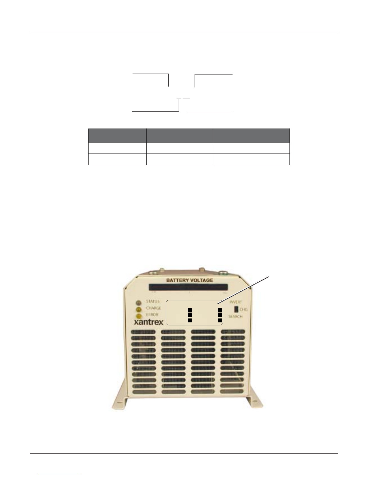
Figure 3-1 Trace UR-UPS Control Panel ...................................................................23
Figure 3-2 3-Stage Battery Charger Graph ............................................................. 27
Figure B-1 Series Configuration for Battery Connections .................................... B-10
Figure B-2 Parallel Configuration for Battery Connections ................................. B-11
Figure B-3 Series-parallel Configuration for Battery Connections ...................... B-11
Page 7
©2002 Xantrex Technology Inc. All Rights Reserved
P/N 975-0049-01-01 Rev A 10/2002
vii
Important Safety Instructions
This manual contains important safety instructions that
should be followed during the installation and
maintenance of this product.
To reduce the risk of electrical shock, and to ensure the safe
installation and operation of this product, these safety
symbols have been placed throughout this manual to
indicate dangerous conditions and important safety
instructions.
• All electrical work must be done in accordance with local,
national, and/or international electrical codes.
• Before installing or using this device, read all instructions
and cautionary markings located in this manual, on the
unit itself, and/or on the generator.
• Do not expose this unit to rain, snow, or liquids of any
type. This product is designed only for indoor usage.
• To reduce the chance of short circuits, always use
insulated tools when installing or working with electrical
appliances of any kind.
•Remove all jewelry while installing this system. This will
greatly reduce the chance of accidental exposure to live
circuits.
• The unit contains more than one live circuit (e.g., grid
and/or generator, or batteries. Power may be present at
more than one source.
• This product contains no user-serviceable parts. Do not
attempt to repair this unit.
• To reduce risk of electric shock, disconnect all wiring
before attempting any maintenance or cleaning. Tur ni ng
off the device may not reduce this risk. As long as AC
input power is present, AC power may pass through the
unit regardless of the ON/OFF switch position.
CAUTION: This
procedure is
critical to the safe
installation or
operation of the
unit. Follow these
instructions
closely.
ATTENTION: Cette
procédure est
essentielle à
linstallation ou
lutilisation de
lunité en toute
sécurité. Suivre
ces instructions de
près.
NOTE: This statement is
important. Follow
instructions
closely.
NOTE: Cette déclaration
est importante.
Suivre les
instructions de
près.
WARNING: A
DANGEROUS
VOLTAGE OR
CONDITION EXISTS
IN THIS AREA.
USE EXTREME
CAUTION WHEN
PERFORMING
THESE TASKS.
AVERTISSEMENT:
UNE TENSION OU
CONDITION
DANGEREUSE
EXISTE DANS
CETTE ZONE. FAIRE
PREUVE
DEXTRÊME
PRUDENCE LORS
DE LA
RÉALISATION DE
CES TÂCHES.
Page 8

viii
©2002 Xantrex Technology Inc. All Rights Reserved.
P/N 975-0049-01-01 Rev A 10/2002
Battery Safety Information
• Always wear eye protection, such as safety glasses, when
working with batteries.
• Remove all loose jewelry before working with batteries.
• Never work alone. Have someone assist you with the
installation or be close enough to come to your aid when
working with batteries.
• Always use proper lifting techniques when handling
batteries.
• Always use identical types of batteries.
• Never install old or untested batteries. Check each
battery’s date code or label to ensure age and type.
• Batteries are temperature sensitive. For optimum
performance, they should be installed in a stable
temperature environment.
• Batteries should be installed in a well vented area to
prevent the possible buildup of explosive gasses. If the
batteries are installed inside an enclosure, vent its highest
point to the outdoors.
• When installing batteries, allow at least 1 inch of air space
between batteries to promote cooling and ventilation.
• NEVER smoke in the vicinity of a battery or generator.
• Use insulated tools when working with batteries.
• When connecting batteries, always verify proper
voltage and polarity.
• Do not short-circuit battery cables. Fire or explosion
can occur.
• In the event of exposure to battery electrolyte, wash the
area with soap and water. If acid enters the eyes, flood
them with running cold water for at least 15 minutes and
get immediate medical attention.
• Always recycle old batteries. Contact your local recycling
center for proper disposal information.
Page 9

1
©2002 Xantrex Technology Inc. All Rights Reserved.
P/N 975-0049-01-01 Rev A 10/2002
1.0 Introduction
Thank you for purchasing the Trace Unrestricted RunTime - Uninterruptible Power System (UR-UPS) from
Xantrex Technology Inc. The Trace UR-UPS takes DC
energy stored in a battery, or battery-bank, and converts
it to usable AC power to provide backup support in the
event of a power failure. When AC power is restored, the
UR-UPS recharges the batteries and keeps them ready
for future use.
Internal circuity protects the batteries from overdischarge by shutting down the inverter when a userdefined, low-battery condition occurs. The control panel
features LEDs for reading system status.
The Trace UR-UPS is microprocessor-controlled and
produces a modified sine wave for use with a variety of
electrical appliances, including computers.
Basic Features and Functions
Basic features and functions include the following.
• 500 or 1000 watts output (depending on model) for
entry-level, backup power applications
• Models for 12-volt or 24-volt DC input
• Automatic transfer to inverter mode when the AC
supply is interrupted, with selectable transfer
sensitivity
• Duplex, 15-amp, grounded AC outlets
(120 Vac/60 Hz models only)
• 15 amp, AC pass-through circuit, with selectable
threshold for AC input
• Configurable battery type selection for liquid or gel type
batteries
• Three-stage battery charger
• Control-panel LEDs for status and error indication
• Battery voltage indicator
• Selectable low-battery cut-out to protect the batteries
from over-discharge
• Automatic cooling fan
Figure 1-1
TRACE UR-UPS (Unrestricted Run-time - Uninterruptible Power System)
Page 10

2
1.0 Introduction
©2002 Xantrex Technology Inc. All Rights Reserved.
P/N 975-0049-01-01 Rev A 10/2002
Unpacking and Inspection
• Carefully unpack the unit from its shipping carton.
• Verify all of the items listed below are present.
– One (1) Trace Unrestricted Run-Time Uninterruptible
Power System (UR-UPS)
– Two (2) Battery Cable Caps (one black and one red)
– One (1) Owner’s Manual
Please call Xantrex Customer Service at 1-800-670-0707
(toll free) or 1-604-422-2777 (direct) if any items are
missing.
• Save your proof-of-purchase. This is required if the unit
should require warranty service.
• Save the original shipping carton and packing materials!
If the unit ever needs to be returned for service, it should
be shipped in the original carton. This is also a good way
to protect the unit if it ever needs to be moved.
• Record the unit’s model, serial number and date of
purchase in the appropriate fields in section
Appendix B - Product Information and Warranty.
Model Identification and Numbering Conventions
The Trace UR-UPS is identified by the model number label
located below the voltage meter on the control panel. All
the necessary information is provided on the label such as
AC output voltage, power, and frequency.
See Figure 1-3, Model Number Sticker, on page 3.
The model number describes the type of technology, the
output specifications, the required battery voltage, the
output voltage, and frequency.
“DR” indicates the type of inverter/charger technology
- DR Series
“UR” Unrestricted Run-time
“UPS” Uninterruptable Power System
“5” the first one (or two) digits of the numerical
designator indicate the unit’s output power e.g., 500 Watts
“12” the last two digits indicate the required nominal
battery bank voltage - e.g., 12 Vdc
“E” designates output frequency. No letter indicates
60 hertz models.
Page 11
3
1.0 Introduction
©2002 Xantrex Technology Inc. All Rights Reserved.
P/N 975-0049-01-01 Rev A 10/2002
Figure 1-2
Product Identification
Letter Suffix Output Voltage Output Frequency
(no letter) 120 VAC 60 Hz
E* 230 VAC 50 Hz
*Not Available at this time
Figure 1-3
Model Number Sticker
Model Identification and Numbering Conventions (continued)
DR512 UR-UPS
DR524 UR-UPS
OEM1
DR1012 UR-UPS
DR1024 UR-UPS
OEM2
Model
Example: DR 512 E
Product Family
Output Power
Battery Voltage
Output Frequency*
Model
Number
Sticker
Page 12

4
1.0 Introduction
©2002 Xantrex Technology Inc. All Rights Reserved.
P/N 975-0049-01-01 Rev A 10/2002
Notes:
Page 13

5
©2002 Xantrex Technology Inc. All Rights Reserved.
P/N 975-0049-01-01 Rev A 10/2002
2.0 Installation
Materials Required
The following items are required for this installation.
• One (1) Trace Unrestricted Run-Time - Uninterruptible
Power System (UR-UPS)
• Two (2) Battery Cable Caps (one black and one red)
(provided) (optional to use)
• One (1) Owner’s Manual
• Two (2) pre-cut 2x4s for mounting the unit on the wall
(optional)
• Four (4) #10 wood screws of sufficient length to
penetrate the 2x4s and 1½" into the wall studs
(optional)
• For units requiring hardwiring of the AC input and
output, adequate wire of appropriate size and length to
comply with local electrical standards and regulations.
• Appropriately sized battery, or battery-bank, to support
the desired loads.
See Appendix B for information on batteries and
battery-banks.
• Appropriately sized battery cables.
See Table 2-2 for the recommended sizes for battery
cables based on the distance from the Trace UR-UPS.
• DC fuse or disconnect device.
See page 16 for additional information on DC fuses
and DC disconnect devices.
Tools Required
The following tools may be needed to complete this
installation.
• Wire strippers
• Phillips screw driver
• Drill
• Slotted screw driver ¼" (6 mm) blade
• Torque wrench
• Needle-nose pliers
• Measuring tape or yard stick
Page 14

6
2.0 Installation
©2002 Xantrex Technology Inc. All Rights Reserved.
P/N 975-0049-01-01 Rev A 10/2002
Mounting
The Trace UR-UPS is designed for indoor use only. It can
be mounted on a shelf or a table next to the batteries or
mounted to a wall. Make sure the location has very good
ventilation.
If wall mounting is used, extra support must be provided
as wallboard is not strong enough to support the weight
of the unit (approximately 30 lbs). The easiest method
for securing the unit to an existing wall is to place two
2x4s horizontally on the wall (spanning at least three (3)
studs) and securing the unit to the 2x4s.
To Mount the Trace UR-UPS to the Wall
1. Locate the studs and mark their location on the wall.
2. Measure the desired height from the floor for the unit
to be mounted.
3. Place a pre-cut 2x4 on the marked location and drill
pilot holes through the 2x4s and studs.
4. Secure the 2x4 with #10 wood screws of sufficient
length to penetrate 1½ inches into the studs.
5. Repeat steps 3 and 4 above for the second 2x4.
6. Secure the Trace UR-UPS to the 2x4s using the four
(4) keyhole slots and six (6) mounting holes as shown
in Figure 2-1.
NOTE: Before mounting
the Trace UR-UPS
to a wall, be sure
to configure the
internal jumpers
according to your
specific
installation
requirements.
See pages 9 through
14 for specific
instructions on
changing jumper
settings.
NOTE: Do not locate the
unit in the same
enclosure with
liquid batteries.
These batteries can
produce explosive
gases and must be
well ventilated.
It is recommended
to use a battery
enclosure that is
vented to the
outdoors for these
types of batteries.
Page 15

7
2.0 Installation
©2002 Xantrex Technology Inc. All Rights Reserved.
P/N 975-0049-01-01 Rev A 10/2002
Figure 2-1
Wall-mounting the Trace UR-UPS
Wallboard
Wall Stud s
16 inches on center
2x4
m
ounting
supports
5 15/16"
c-c
TRACE UR-UPS
7 1/8" 7 1/8"
14 ¼"
10 ½"
5 ¼"
Keyhole Slots
(X4)
Mounting Holes
(X6)
Mounting (continued)
To Mount the Trace UR-UPS to the Wall (continued)
Page 16
8
2.0 Installation
©2002 Xantrex Technology Inc. All Rights Reserved.
P/N 975-0049-01-01 Rev A 10/2002
Configuration Options
Before connecting the Trace UR-UPS to the AC or DC
power source, configure the unit for the following:
• AC Transfer Voltage Sensitivity (JP1)
• Battery Type (JP2)
• Battery Depth-of-Discharge Voltage (JP3)
• Option B (JP4) - Not used at this time.
See pages 9-14 for instructions on setting specific
configuration selections.
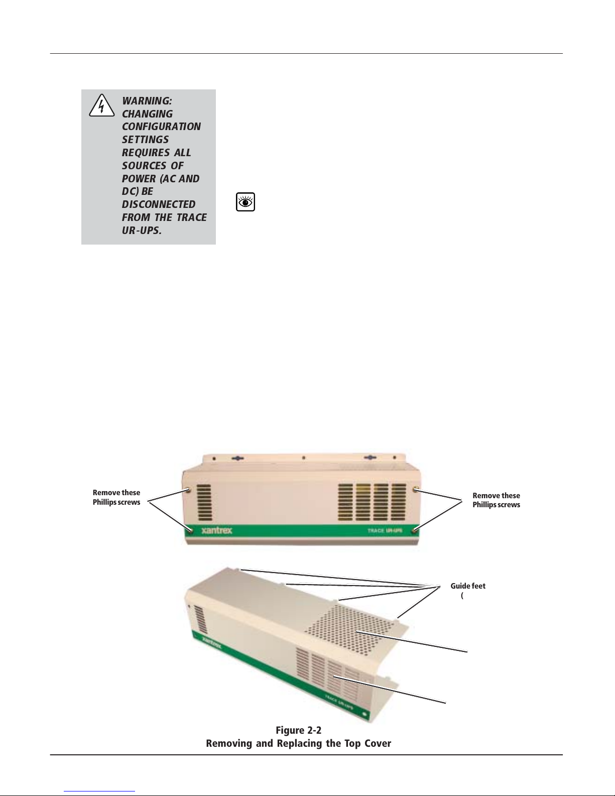
To Remove the Top Cover
1. Removing the four Phillips screws from the top of the
unit.
2. Lift the cover off the unit.
Replacing the Top Cover
1. Set the cover back on the unit ensuring the guide feet
insert properly into the base and the ventilation
holes are on the top. The four rows of ventilation slots
must be on the right hand side.
2. Replace the four Phillips screws from the front of the
unit.
WARNING:
CHANGING
CONFIGURATION
SETTINGS
REQUIRES ALL
SOURCES OF
POWER (AC AND
DC) BE
DISCONNECTED
FROM THE TRACE
UR-UPS.
Figure 2-2
Removing and Replacing the Top Cover
Remove these
Phillips screws
Remove these
Phillips screws
Guide feet
(X8)
Top of Cover
Ventilation Holes
Ventilation Slots
Page 17
9
2.0 Installation
©2002 Xantrex Technology Inc. All Rights Reserved.
P/N 975-0049-01-01 Rev A 10/2002
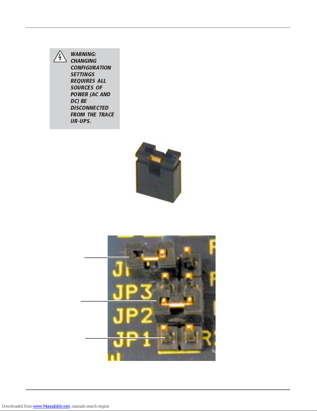
Figure 2-4
Jumper Placement
Figure 2-3
Jumper Enlargement
Jumper On
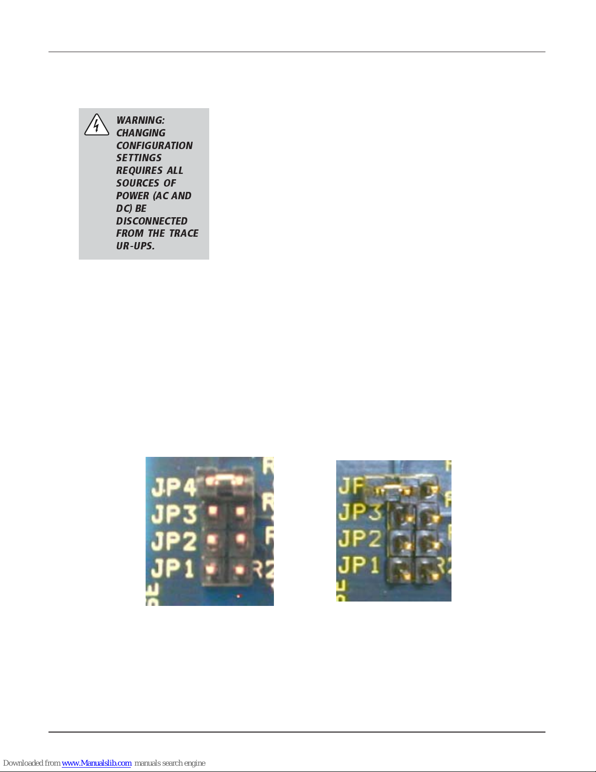
To Configure the Trace UR-UPS
The Trace UR-UPS has four jumpers to control its
operation. A jumper is a small, rectangular piece of plastic
with two square holes in it that fit over two pins. A jumper
contains an internal conductor that joins the two pins
completing a circuit. When the jumper is removed, the
circuit is interrupted.
When a jumper is not connecting the two pins, it can be
stored by slipping it over just one of the pins instead of
both. This will have no effect upon the configuration but
will keep the jumper available for future use.
Jumper Off
(Stored)
Empty Pins
WARNING:
CHANGING
CONFIGURATION
SETTINGS
REQUIRES ALL
SOURCES OF
POWER (AC AND
DC) BE
DISCONNECTED
FROM THE TRACE
UR-UPS.
Page 18
10
2.0 Installation
©2002 Xantrex Technology Inc. All Rights Reserved.
P/N 975-0049-01-01 Rev A 10/2002
To Configure the Trace UR-UPS (continued)
The jumpers in the Trace UR-UPS are located on the
main circuit board and are labeled JP1 for AC transfer
sensitivy, JP2 for battery type selection, JP3 for depth-ofdischarge, and JP4 for Option B (which is not used at this
time).
1. To access the jumpers, remove the top cover from the
unit following the instructions on page 8.
2. Locate the configuration jumpers on the main
printed circuit board.
3. Either install or remove (store) the jumpers
depending upon the desired configuration. Use
needle-nose pliers to carefully remove the jumpers.
Table 2-1
Jumper Settings
Figure 2-5
Jumper Location
CAUTION: Be
extremely careful
when removing
and/or installing
the jumpers. Do
NOT bend the pins
as permanent
damage to the
circuit board can
occur.
Jumper Location
repmuJ
DI
noitcnuF )tluafeD(NOrepmuJ FFOrepmuJ
1PJ
refsnarTCA
ytivitisneS
)tuonworB(
edoMSPU
caV031-501
smr
edoMNEG
caV041-09
smr
2PJ
epyTyrettaB
noitceleS
)MGA(/)leG(delaeS
cdV3.41=kluB
setunim06=emiTnoitprosbA
cdV4.31=stloVtaolF
)dicAdaeLdedoolF(diuqiL
cdV7.41=kluB
setunim06=emiTnoitprosbA
cdV2.31=stloVtaolF
3PJ
egrahcsiDfohtpeD
egatloVwoL(
))DVL(egrahcsiD
egrahcsiDpeeD
>
cdV6.01
egrahcsiDwollahS
<
cdV7.11
4PJ BnoitpO DESUTON DESUTON
Main Circuit Board
Page 19
11
2.0 Installation
©2002 Xantrex Technology Inc. All Rights Reserved.
P/N 975-0049-01-01 Rev A 10/2002
To Configure the Trace UR-UPS (continued)
Setting AC Transfer Sensitivity (JP1 - BROWNOUT)
The Transfer Sensitivity jumper sets the voltage limits
which the AC input voltage can fall or rise to before the
unit switches to the battery (or batteries) to power the
load.
Refer to Table 2-1, on page 10, for the AC transfer
voltage ranges of the Trace UR-UPS.
Two settings are available: GEN for generator supplied
power, and UPS (default) for utility supplied power.
Since some generators may have wide fluctuations in the
output voltage, selecting GEN MODE allows the range of
acceptable voltage to be from 90–140 Vac before the unit
switches to batteries. In the UPS MODE, the tolerance for
utility supplied power is from 105–130 Vac.
To Select UPS MODE (Default) (105 - 130 Vac)
• JUMPER ON: Place the jumper on both contact pins.
To Select GEN MODE (90 - 140 Vac)
• JUMPER OFF: Remove the jumper from the contact pins
and place it over only one of the pins. This will keep the
jumper available for future use.
Figure 2-6
Setting AC Transfer Sensitivity (JP1)
To select UPS MODE,
leave the jumper ON
(This is the default configuration.)
To select GEN Mode,
take the jumper OFF and place
it over only one pin.
WARNING:
CHANGING
CONFIGURATION
SETTINGS
REQUIRES ALL
SOURCES OF
POWER (AC AND
DC) BE
DISCONNECTED
FROM THE TRACE
UR-UPS.
NOTE: This unit requires
a well-regulated
generator for
optimal
performance.
NOTE: Transfer time from
utility to inverter is
approximately
8-10 milliseconds
with the loss of
grid power.
Page 20
12
2.0 Installation
©2002 Xantrex Technology Inc. All Rights Reserved.
P/N 975-0049-01-01 Rev A 10/2002
Setting Battery Type (JP2 - Gel/Liquid)
The Trace UR-UPS can charge GEL or LIQUID batteries.
The different types of batteries require specific charging
voltages.
Refer to Table 2-1, on page 10, for the bulk,
absorption, and float mode charging values of the
Trace UR-UPS.
Determine what type of battery will be used before
changing the battery-type jumper. The default setting is
for Gel batteries.
If your battery chemistry is something other than Gel or
Liquid, contact your battery manufacturer for information
on the best voltage level to use for charging. If they do not
support the voltage levels indicated on Table 2-1 on page 9,
use different batteries.
To Select GEL Battery Charging (Default)
• JUMPER ON: Place the jumper on both contact pins.
To Select LIQUID Battery Charging
• JUMPER OFF: Remove the jumper from both contact
pins and place it over only one of the pins. This will keep
the jumper available for future use.
To Configure the Trace UR-UPS (continued)
Figure 2-7
Battery Type Selection (JP2)
To select Liquid Batteries,
leave the jumper OFF
and placed over only one pin.
To select Gel Batteries,
place the jumper ON the two pins.
(This is the default configuration.)
WARNING:
CHANGING
CONFIGURATION
SETTINGS
REQUIRES ALL
SOURCES OF
POWER (AC AND
DC) BE
DISCONNECTED
FROM THE TRACE
UR-UPS.
NOTE: Using batteries
that require
different voltage
levels that those
indicated in
Table 2-1 can result
in shortened
battery life or even
damage the
batteries and can
adversely affect
performance by
the Trace UR-UPS.
Page 21
13
2.0 Installation
©2002 Xantrex Technology Inc. All Rights Reserved.
P/N 975-0049-01-01 Rev A 10/2002
To Configure the Trace UR-UPS (continued)
Setting Depth-of-Discharge (JP3 - LVD)
The DEPTH-OF-DISCHARGE jumper sets the battery
voltage for DEEP or SHALLOW discharge.
In DEEP discharge mode, the unit continues to supply AC
output power to the load until the batteries have
discharged to 10.6 Vdc for one minute. This allows the
batteries to discharge almost completely. The unit’s runtime will be longer in this mode and there will be fewer
charge/discharge cycles. DEEP discharge is the default
factory setting (jumper on).
In shallow discharge mode, the unit continues to supply AC
output power to the loads until the batteries have
discharged to 11.7 Vdc for a period of five minutes. This
causes less stress on the batteries resulting in longer
battery life. The unit’s run-time will be shorter in this
mode and the batteries will receive more charge/discharge
cycles.
To Select DEEP Depth-of-Discharge (Default)
• JUMPER ON: Leave the jumper on both contact pins.
To Select SHALLOW Depth-of-Discharge
• JUMPER OFF: Remove the jumper from both contact
pins and place it over only one of the pins. This will keep
the jumper available for future use.
Figure 2-8
Setting Depth-of-Discharge (JP3)
To select SHALLOW Depth-of-Discharge,
leave the jumper OFF and placed over only
one pin.
To select DEEP Depth-of-Discharge,
place the jumper ON the two pins.
(This is the default configuration.)
NOTE: DEEP discharge
will increase run
time but may
decrease battery
life.
WARNING:
CHANGING
CONFIGURATION
SETTINGS
REQUIRES ALL
SOURCES OF
POWER (AC AND
DC) BE
DISCONNECTED
FROM THE TRACE
UR-UPS.
Page 22
14
2.0 Installation
©2002 Xantrex Technology Inc. All Rights Reserved.
P/N 975-0049-01-01 Rev A 10/2002
To Configure the Trace UR-UPS (continued)
Setting Option B (JP4 - OPTION B) (Not used)
This jumper assignment is currently not used. Disregard
this jumper setting until further notice or unless told to
remove it by an authorized Xantrex Customer Service
Representative.
• JUMPER ON: Default position (N/A)
• JUMPER OFF: N/A
Figure 2-9
Setting Option B (JP4) (Not Used at this time)
Jumper OFF: Do not remove the jumper
unless instructed to do so by an authorized
Xantrex Customer Service Representative.
Jumper ON: This is the default configura-
tion.
WARNING:
CHANGING
CONFIGURATION
SETTINGS
REQUIRES ALL
SOURCES OF
POWER (AC AND
DC) BE
DISCONNECTED
FROM THE TRACE
UR-UPS.
Page 23

15
2.0 Installation
©2002 Xantrex Technology Inc. All Rights Reserved.
P/N 975-0049-01-01 Rev A 10/2002
DC Wiring
Figure 2-10
DC Connections
WARNING: READ
THE IMPORTANT
SAFETY
INSTRUCTIONS IN
THIS MANUAL
AND THE BATTERY
SUPPLIERS
PRECAUTIONS
BEFORE
INSTALLING THE
TRACE UR-UPS
AND BATTERIES.
POSITIVE (+)
DC Connection
NEGATIVE ()
DC Connection
Chassis
Ground Lug
DC Grounding
1. Connect one end of a (green) #8 AWG ground wire to
the Chassis Ground Lug.
2. Connect the other end of the ground wire to the
negative (–) terminal on the battery.
3. Run another #8 AWG ground wire from the battery’s
negative (–) terminal to the main utility panel’s
ground bar or grounding electrode.
WARNING: BE
VERY CAREFUL
WHEN WORKING
WITH BATTERIES.
BATTERIES CAN
PRODUCE
EXTREMELY HIGH
CURRENTS IF
SHORT-CIRCUITED.
Table 2-2
Recommended Battery Cable Sizes
#ledoM
ecnatsiD
teef5-0 teef01-5
SPU-RU215RDGWA4GWA2
SPU-RU2101RDGWA2GWA1
SPU-RU425RDGWA6GWA4
SPU-RU4201RDGWA4GWA2
NOTE: Cable sizes listed
in Table 2-2 are
recommendations
only. Consult your
local electrical
codes to ensure
compliance.
Page 24

16
2.0 Installation
©2002 Xantrex Technology Inc. All Rights Reserved.
P/N 975-0049-01-01 Rev A 10/2002
DC Wiring (continued)
DC Disconnect and Over-current Protection
For safety and compliance with national electrical codes
and regulations, battery over-current protection is
required. Fuses and disconnects must be sized to
protect the wiring in the system and are required to open
before the wire reaches its maximum current carrying
capability.
The National Electrical Code (NEC) requires both overcurrent protection and a disconnect switch for
residential and commercial electrical systems.
When sizing the DC disconnect, the expected
continuous load on the unit should be used to
determine the DC current. Efficiency loss through the
unit increase the DC current draw and must be
accounted for. Divide the maximum continuous current
draw by the unit’s efficiency. Add a 25% safety margin to
comply with code requirements.
The term “free air” is defined by the NEC as cabling that
is not enclosed in a conduit or a raceway. Cables
enclosed in conduit or raceways have substantially lower
continuous current carrying ability due to heating
factors.
Some installations may not require conduit or a
disconnect device, although over-current protection is
still required.
To protect the battery wiring in the event of a shortcircuit, the installation should include a class-T, DC fuse
with a disconnect switch in the positive line between the
unit and the batteries. Consult your local electrical
codes for the appropriate size of this DC disconnect
based on the size of the DC cables being used for this
installation. DC disconnect and over-current protection
(fuse) are not provided with the unit.
NOTE: Consult your local
electrical code for
exact DC
disconnect and
over-current
protection
requirements.
See your local
dealer for
obtaining the
correct hardware
for your
installation.
Page 25

17
2.0 Installation
©2002 Xantrex Technology Inc. All Rights Reserved.
P/N 975-0049-01-01 Rev A 10/2002
DC Wiring (continued)
Connection to the Battery
See Figure 2-10 on page 15 for the location of the DC
connectors.
See Figure 2-11 on page 18 for proper connection of
the battery cable.
See Figure 2-12 on page 18 for a photograph of the
battery cable caps.
1. If using copper compression lugs on the battery cables,
slide the red cable cap onto a positive (red) battery
cable with the cap side closest to the DC connectors on
the Trace UR-UPS. Slide the black cable cap onto a
negative (–) battery cable with the cap side closest to
the DC connectors on the Trace UR-UPS.
If using aluminum mechanical lugs on the battery
cables, the cable caps may not fit. If this is the case, do
not use the cable caps and proceed with the following
steps below.
2. Connect the red, positive (+) battery cable to the
positive (+) DC connector on the Trace UR-UPS.
3. Connect this red, positive (+) battery cable to a
DC fuse and DC disconnect switch (not supplied).
4. Connect another red, positive (+) battery cable to the
other end of the DC fuse and DC disconnect switch.
5. Connect the negative (–) battery cable to the
negative (–) DC connection on the Trace UR-UPS.
6. Connect the second, positive (+) battery cable
connected to the DC fuse and disconnect directly to
the positive (+) battery terminal. Ensure the cable’s
lug is flush against the battery’s terminal.
7. Connect the negative (–) battery cable directly to the
negative (–) battery terminal. Ensure the cable’s lug is
flush against the battery’s terminal.
8. Torque these connections according to the battery
manufacturer’s specifications.
9. After all the connections are made, coat the terminals
with an approved anti-corrosive compound available at
a battery or automotive supplier. Only coat the
terminals AFTER the connections are made and
torqued.
10. If using the cable caps, slide the red and black cable
caps over the red (+) and black (–) connectors
(respectively) on the Trace UR-UPS.
NOTE: When connecting
the cables to the
unit, there may be
a brief spark and
snapping sound as
the unit’s
capacitors charge.
This is normal.
NOTE: Ensure the battery
terminals are
clean, without any
type of coating,
prior to connecting
the wiring/cables.
CAUTION:
Observe battery
polarity before
connecting the
units wires to the
battery. Failure to
do so will damage
the Trace UR-UPS.
This type of
damage is not
covered under
warranty.
WARNING: DO
NOT ALLOW
TOOLS TO TOUCH
THE CONNECTORS
WHEN INSTALLING
THE CABLES. ALSO
DO NOT ALLOW
THE ENDS OF THE
CABLES TO TOUCH
EACH OTHER AFTER
BEING CONNECTED
TO THE BATTERY
AND BEFORE BEING
CONNECTED TO THE
UNIT.
Page 26

18
2.0 Installation
©2002 Xantrex Technology Inc. All Rights Reserved.
P/N 975-0049-01-01 Rev A 10/2002
Figure 2-11
Battery Cable Connections
&RSSHU& RPSUHVV LRQ/XJ $OXPLQXP0HF KD QLFD O/XJ
' RQRWSODFHDQ\WKLQJEHWZHHQED WW HU\FDEOH
OXJDQGWKHED WW HU\WHUPLQDOVXUIDFH
$VVHPEOHH[ D FW O\D VVKRZQ
%DWWHU\
7HU PL QDO
6XU I DFH
%DW W HU \
&DE O H
/XJ
%DW W HU \
&DE O H
/XJ
%DWWHU\
7HU PL QDO
6XU I DFH
Figure 2-12
Battery Cable Caps
Battery Cable Caps
Slide battery cable caps
over the DC connectors
DC Wiring (continued)
Connection to the Battery (continued)
Page 27

19
2.0 Installation
©2002 Xantrex Technology Inc. All Rights Reserved.
P/N 975-0049-01-01 Rev A 10/2002
AC Wiring
Prewired AC Input and Output
Insert the AC input plug into a properly grounded,
120 Vac outlet receptacle.
Insert the load’s power cord (from an AC appliance)
into the unit’s output receptacle.
CAUTION: To reduce
the risk of fire, use
only AC input
circuits protected
by a 20 ampere
branch circuit
breaker.
CAUTION: Do not
connect the AC
input plug into
the units output
receptables.
Figure 2-13
AC Input Plug and Output Receptacles
AC Input Plug
AC Grounding
AC input plug must be connected to a properly grounded
wall outlet.
Models with the prewired AC input cord and outlets have
the AC ground connected to the chassis.
The bonding of the AC ground wire to neutral must be
provided by the AC charging source used by the unit for
recharging the batteries.
WARNING: FAILURE
TO USE A PROPERLY
GROUNDED WALL
OUTLET MAY
CREATE A
POTENTIAL SHOCK
HAZARD.
120 Vac output
receptacles
Page 28

20
2.0 Installation
©2002 Xantrex Technology Inc. All Rights Reserved.
P/N 975-0049-01-01 Rev A 10/2002
AC Wiring (continued)
Hardwiring the AC Input and Output (if required)
Some models may require you to hardwire the AC input
and output. If your unit requires hardwiring the AC input
and output, follow the directions on pages 21 through 22.
Use a minimum 14 AWG, solid wire for all input and
output wiring. Check with your local electrical codes for
absolute compliance on this wire size.
Knockout Preparation
Remove the knockouts from the end panel as shown
below for AC IN and AC out wiring.
Figure 2-14
Knockout locations for AC IN and AC OUT Wiring
Two (2)
Knockouts for
½” conduit or
strain relief
½” conduit or
strain relief
Output receptacles may
or may not be present
on these models.
Page 29

21
2.0 Installation
©2002 Xantrex Technology Inc. All Rights Reserved.
P/N 975-0049-01-01 Rev A 10/2002
AC Wiring (continued)
Hardwiring the AC Input and Output (if required)
Input Wiring
1. Install a conduit or strain relief in the rear panel AC IN
knockout hole.
2. Feed the AC input cord (from the generator or main
utility panel) through the strain relief.
3. Strip all wires back approximately 3/8 inch (10 mm).
4. Connect the green/yellow (ground) wire to the lower
terminal on the main PC board.
5. Connect the blue or white (neutral) wire to the center
terminal on the main PC board.
6. Connect the brown or black (hot) wire to the upper
terminal on the main PC board.
7. Torque all screws to 16 inch-lb (1.8 Nm).
8. Tighten the screws on the strain relief (leave some slack
in the wire before tightening).
9. Proceed to output wiring.
CAUTION: TO
REDUCE THE RISK
OF FIRE, USE ONLY
AC INPUT CIRCUITS
PROTECTED BY AN
APPROPRIATELY
SIZED DC BRANCH
CIRCUIT BREAKER.
HOT
NEUTRAL
GROUND
Figure 2-15
Wiring AC Input to Terminal Block
Page 30

22
2.0 Installation
©2002 Xantrex Technology Inc. All Rights Reserved.
P/N 975-0049-01-01 Rev A 10/2002
AC Wiring (continued)
Hardwiring the AC Input and Output (if required)
Output Wiring
1. Install a conduit or strain relief in the rear panel AC
OUT knockout hole.
2. Feed the AC output cord through the strain relief to the
subpanel designated for the desired loads for the Trace
UR-UPS (not the main electrical utility box).
3. Strip all wires back approximately 3/8 inch (10 mm).
4. Connect the green/yellow (ground) wire to the lower
terminal on the main PC board.
5. Connect the blue or white (neutral) wire to the center
terminal on the main PC board.
6. Connect the brown or black (hot) wire to the upper
terminal on the main PC board.
7. Torque all screws to 16 inch-lb (1.8 Nm).
8. Tighten the screws on the strain relief (leave some slack
in the wire before tightening).
9. Reinstall the cover following the instructions on
page 8.
HOT
NEUTRAL
GROUND
Figure 2-16
Wiring AC Output to Terminal Block
Page 31

23
©2002 Xantrex Technology Inc. All Rights Reserved.
P/N 975-0049-01-01 Rev A 10/2002
3.0 Operation
Basic Control Panel Features
The Trace UR-UPS control panel includes the following
items.
• A slide switch for setting its mode of operation: INVERT,
CHG, or SEARCH
• Green STATUS LED - indicates whether or not the unit is
active
• Yellow CHARGER status LED - indicates that the unit is
in charger mode
• Red/Yellow ERROR status LED - indicates an error
condition
See Table 3-1 for a description of the various
meanings of the LED indicators.
• Battery Voltage Meter - indicates the voltage level of the
batteries
Figure 3-1
Trace UR-UPS Control Panel
Operational
Status LED
Charge
Status
LED
Error
Status
LED
Slide Switch
Battery
Voltage
Meter
Page 32

24
3.0 Operation
©2002 Xantrex Technology Inc. All Rights Reserved.
P/N 975-0049-01-01 Rev A 10/2002
Modes of Operation
Once the batteries have been connected, the unit
becomes operational and performs a quick self-test.
When AC power is present at the inputs, the unit
performs as a charger regardless of the position of the
slide switch on the control panel.
When no AC input power is present, the slide switch
provides a manual method of selecting operational
modes for the unit (e.g., INVERT, CHG, and SEARCH
modes).
INVERT Mode
When the unit is in INVERT mode and it detects no AC
power available at its input plug, it will take DC power
from the battery and inverts it to AC power. That AC
power is then routed to the AC output receptacles to
power the AC loads connected to it. The duration of time
the unit can invert power is directly related to the size of
the battery (or battery bank).
To run the unit in “INVERT” mode, move the slide switch
to INVERT on the control panel.
CHG Mode
When no AC power is present, this is the OFF position for
the unit and will not provide backup power to the
connected loads. When the unit is in CHG mode and it
detects AC power available at it’s input plug, it will route
power to the battery charger and charge the batteries
back up to the specified level.
To run the unit in “CHG” mode, move the slide switch to
CHG on the control panel.
SEARCH Mode
To conserve battery power when an input source of AC
voltage is not available (as during a grid failure), the
SRCH mode can be selected. In this mode, the unit
checks the AC output circuit to see if a load has been
turned ON. If it detects a load, the unit switches to full
output power to operate the load. When the load is
switched OFF, the unit resumes its sleep mode and
continues to monitor the output circuit.
To run the unit in SEARCH Mode, move the slide switch
on the control panel to the SEARCH position.
The unit is now set to switch OFF the AC output during a
grid failure until the minimum load requirements are
met.
NOTE: Selecting search
mode may result
in a slower
transfer for power
in the event of a
power outage.
Page 33

25
3.0 Operation
©2002 Xantrex Technology Inc. All Rights Reserved.
P/N 975-0049-01-01 Rev A 10/2002
LED Indicators
The side panel contains LEDs indicating the unit’s
status. These LEDs flash at predetermined rates to
indicate a specific mode of operation or error condition.
Table 3-1
Status Indicator LEDs
SROTACIDNIDEL
DEL
noitacidnInoitpircseD
SUTATS
)neerG(
FFO
.ffositinuehT
gnihsalF
.edomHCRAESnisitinuehT
diloS
.edomTREVNInisitinuehT
REGRAHC
)wolleY(
hsalFwolS )dnocesrepecno(
teytonsahretrevni,tneserpsiCAytilitU
yllausussecorpsihT.edomegrahCotderrefsnart
sirewopytilituretfasdnoces02tuobasekat
.retrevniehtotdeilppa
hsalFtsaF )dnocesrepnet(
ehtniseirettabehtgnigrahcsiregrahcehT
.edomnoitprosba/klub
wolleYdiloS
.edomtaolfehtnignigrahcsiregrahcehT
rorrE
)wolleY/deR(
wolleY diloS
NOITIDNOCYRETTAB-HGIHegatlovyrettabehT.
.stimilstinuehtsdeecxe
wolleY gnihsalF
NOITIDNOCYRETTAB-WOLsiegatlovyrettabehT.
.stimilstinuehtwoleb
deRhsalFwolS )dnocesrepecno(
foerutarepmetehT.PMETREVOREMROFSNART
.slevelefassdeecxeremrofsnarteht
deRhsalFtsaF )dnocesrepnet(
nosTEFehtfoerutarepmetehT.PMETREVOTEF
.slevelefassdeecxedraobtiucriceht
deRdiloS
.NOITIDNOCDAOLREVO
Battery Voltage Meter
The Battery Voltage Meter provides a visual indication of
the battery voltage level. If the voltage is below 10 Vdc
(20 Vdc for 24-volt units), then the left most LED will
blink. If the voltage is above 15 Vdc (30 Vdc for 24-volt
units), then the right most LED will blink. Between these
voltages, the display changes at ½-volt increments
(1-volt increments for 24-volt units).
Page 34

26
3.0 Operation
©2002 Xantrex Technology Inc. All Rights Reserved.
P/N 975-0049-01-01 Rev A 10/2002
Battery Charger Operation
The Trace UR-UPS is equipped with a three-stage
battery charger.
The batteries receive different charge voltages and
currents, depending on the charger mode. After a utility
grid failure, the charger automatically cycles through the
charging modes. When charging is complete, the
batteries receive a maintenance charge to keep them in
a fully charged, ready state.
BULK
Bulk is the initial stage of charging. In this mode, the
charger’s maximum constant current is supplied to the
batteries. The CHARGE LED flashes once per second to
indicate bulk charge mode. Over time, the battery
voltage rises until the bulk voltage setting is reached
(14.3 Vdc for gel batteries and 14.7 Vdc for liquid
batteries). The charger then switches to absorption
mode.
During this stage of charging, the automatic cooling fan
will be typically running.
ABSORPTION
The charger supplies a constant (bulk) voltage to the
batteries as the charge current is slowly reduced. The
CHARGE LED flashes rapidly (10/sec) during the
absorption stage, lasting approximately 1 hour.
During this stage of charging, the automatic cooling fan
will be typically running.
FLOAT
During the final stage of charging, the batteries are held
at the float voltage (13.6 Vdc for gel batteries and 13.4
Vdc for liquid batteries). This reduces battery gassing,
minimizes watering requirements (for liquid batteries)
and ensures complete battery charging.
The CHARGE LED is ON solid while float charging.
Note: Charging
efficiency is
directly related to
the quality of the
input AC
waveform.
Page 35

27
3.0 Operation
©2002 Xantrex Technology Inc. All Rights Reserved.
P/N 975-0049-01-01 Rev A 10/2002
Figure 3-2
3-Stage Battery Charger Graph
Inverter to Charger Transition
The Trace UR-UPS constantly charges the batteries as
long as power is being supplied to the unit (from either
the utility grid or a generator).
When a utility outage occurs, the unit switches to the
batteries to maintain power to the connected load. This
is accomplished by an automatic transfer relay, rated at
15 amps and protected by a 15 amp circuit breaker.
When the AC utility (or generator) power returns, there is
a built-in 20 second delay before the unit switches from
inverter to charger mode. This delay allows the utility
power to stabilize after an outage, or for the generator to
achieve a stable voltage, thus protecting the connected
load.
Absorption Stage
Bulk Stage
Float Voltage
Charging
Started
Max Charge
Amps
Constant Voltage
Constant Current
Reduced Current and Voltage
DC Voltage
DC Current
Bulk Voltage
80–90% Capacity
100% Capacity
One-Hour Absorption
Period
Float Stage
Battery Charger Operation (continued)
Page 36

28
3.0 Operation
©2002 Xantrex Technology Inc. All Rights Reserved.
P/N 975-0049-01-01 Rev A 10/2002
Notes:
Page 37

29
©2002 Xantrex Technology Inc. All Rights Reserved.
P/N 975-0049-01-01 Rev A 10/2002
4.0 Troubleshooting
Basic Troubleshooting
MOTPMYS MELBORP YDEMER
tuptuOCAoN
nideggulptontinU.drocrewopCAkcehC
GHCnisihctiwsedilstinU
noitisop
.edoMTREVNIothctiwS
deppirtrekaerbtiucricCA.lenapraernorekaerbteseR
selbacdab,seirettabdaeD.selbacdnaseirettabkcehC
wolsituptuoCA
foepytgnorwhtiwgnirusaeM
retemtlov
SMReurTaebtsumretemtloV
.retemgnidaer
seirettabwoL.seirettabegrahcerdnakcehC
wolootegatlovtupniCA
roftiawrodeepsrotarenegtsujdA
.ezilibatsotytilitu
daolsnrutretrevnI
NO/FFO/NO
yrettabdedorrocroesooL
noitcennoc
.snoitcennocnaelcdnakcehC
sidaoleht,edoMHCRAESnifI
hcraesehtgnideecxeton
.levelegattaw
TREVNIothctiwsrodaolehtesaercnI
.edoM
02retfaffostuhsretrevnI
sdnoces
drocrewopCAs'retrevnI
tuptuos'retrevniehtotnideggulp
elcatpecer
.drocenilCAgulpnU
egrahctonlliwserettaB
wolrohgihootegatlovtupniCA
roftiawrodeepsrotarenegtsujdA
.ezilibatsotytilitu
tesylreporpmirepmujlanretnI.gnittesrepmujkcehC
yrettabdedorrocroesooL
noitcennoc
.snoitcennocnaelcdnakcehC
selbacdab,seirettabdaeD
.seirettabecalpeR
egrahcTONlliwretrevniehT:ETON
.seirettabdaed
DELRORREwolleY
)gnihsalf(
wolootsiegatlovyrettaB.egrahcerdnakcehC
DELRORREwolleY
)dilos(
hgihootsiegatlovyrettaB
yltcerrocniebyamseirettaB
ebyamregrahclanretxerodetcennoc
.hgihootgnigrahc
DELRORREdeR
)hsalfwols(
pmetrevOremrofsnarT
ro,tinuehtdnuoranoitalitnevevorpmI
.daolecuderroevomer
DELRORREdeR
)hsalfhsaf(
pmetrevOTEF
ro,tinuehtdnuoranoitalitnevevorpmI
.daolecuderroevomer
DELRORREdeR
)dilosNO(
noitidnocdaolrevO.daolecudeR
Page 38

30
4.0 Troubleshooting
©2002 Xantrex Technology Inc. All Rights Reserved.
P/N 975-0049-01-01 Rev A 10/2002
Potential Brownout Conditions
While operating in INVERT mode, large loads may
temporarily overload the unit causing the output voltage
to sag or drop out. For example, if a computer is being
operated from the unit and someone turns on a TV, the
inrush current for the TV may cause a brownout
condition on the unit causing the computer to reboot.
To minimize this condition:
1. Keep the DC cables as short as possible.
2. Use the largest battery cable gauge possible.
3. Keep the positive and negative DC cables taped side
by side for as long as practical. This helps to reduce
the inductance of the cable.
If problems persist, keep in mind that the unit must take
in a large amount of DC current in order for it to make a
large amount of AC current for the load with a high
inrush current demand. A unit that has incorrectly sized
DC cables, poor connections, or failing batteries is like a
house with a substandard foundation.
Potential Problem Loads for UPS Applications
The unit can operate most AC loads. However, there are
special conditions that can cause a load to behave
differently than expected. The following describes some
of the common problems encountered when using
devices of this nature.
General Issues
Heavy Loads
If the battery-bank cannot deliver the necessary
amperage to operate a heavy load, the unit will shut
down. The battery voltage will then slowly rise back
above the low-voltage threshold causing the inverter to
resume operation. This cycling of the inverter will
continue until the heavy load is reduced or an additional
source of power is added.
CAUTION: Some of
these problem
loads can cause
irreparable
damage to the load
itself. Please
contact the
manufaturer of the
item for more
specific
information on UPS
compatibility
before using any of
these items with
the Trace UR-UPS.
Page 39

31
4.0 Troubleshooting
©2002 Xantrex Technology Inc. All Rights Reserved.
P/N 975-0049-01-01 Rev A 10/2002
Potential Problem Loads for UPS Applications (continued)
General Issues (continued)
Cell Phones
Some cellular telephones experience interference in the
form of a clicking sound.
Consumer Electronics
AM radios, citizen band, amature radio, and wireless
intercom systems tend to pick up inverter noise,
especially on the lower half of their band. Inexpensive
tape recorders are likely to experience noise as well.
Avoid starting large loads when using sensitive electronic
devices.
Waveform Issues
Ceiling Fans
Most large-diameter, slow turning fans run correctly, but
generate more noise than when connected to utility
power. High speed fans tend to operate normally.
Clocks
The unit’s crystal controlled oscillator keeps the
frequency accurate to within a few seconds a day;
however, external loads in the system may alter the unit’s
output waveform causing clocks to run at different
speeds. There may be periods where clocks keep time
correctly and then mysteriously do not. This is because
most clocks do not draw enough power to trigger the load
sensing circuit when in SEARCH mode. In order to
operate, especially with no other loads present, the unit’s
load sensing circuit will have to be defeated (i.e., turn off
the SEARCH Mode).
Dimmer Switches
Most dimmer switches lose their ability to dim the lights
and operate only in the fully ON or OFF position. Newer
dimmer switches controlled by microprocessors tend to
work better in these applications.
Page 40

32
4.0 Troubleshooting
©2002 Xantrex Technology Inc. All Rights Reserved.
P/N 975-0049-01-01 Rev A 10/2002
Potential Problem Loads for UPS Applications (continued)
Waveform Issues (continued)
Microwave Ovens
Microwave ovens are sensitive to peak output voltages.
The higher the voltage, the faster they cook. Since the
unit’s peak output voltage is dependent upon battery
voltage and load size, the microwave’s cook time may
need to be increased.
Printers
Most inkjet type printers work well in these applications.
Most laser printers, however, require a true sinewave
output, as opposed to a modified sinewave output.
Check with your printer manufacturer for UPS
compatibility before using laser printers with this unit.
Rechargeable Devices
When first using a rechargeable device, monitor its
temperature for 10 minutes to ensure it does not become
abnormally hot. Excessive heat will indicate that it is
incompatible with the unit.
Potential Problem Loads related to Search Sense Mode
Some loads can “fool” the Search Sense Mode, causing
the unit to cycle on and off, or not to turn on at all.
Confirming Search Mode Operation
A neon-type nightlight can be used as a test indicator to
show whether the inverter is searching for loads. Plug
the night light into the wall–if the inverter is in search
mode the light will blink, showing the search pulses sent
out by the inverter. If the inverter is running a load, the
light will be on continuously because continuous power
is being delivered to a load. A typical incandescent
nightlight may also work to show the pulses, but it will
use more power.
CAUTION: Check
with your laser
printer
manufacturer for
UPS compatibility
before using laser
printers with a
Trace UR-UPS.
Page 41

33
4.0 Troubleshooting
©2002 Xantrex Technology Inc. All Rights Reserved.
P/N 975-0049-01-01 Rev A 10/2002
Potential Problem Loads related to Search Sense Mode (continued)
Computers and Sensitive Electronics
Some computers and sophisticated electronics have
power supplies that do not present a load until correct
line voltage is available. When this occurs, each unit
waits for the other to begin. This can usually be solved
by plugging in an additional load (such as a lamp) to
bring the unit out of its search mode. Avoid starting
large loads when using a computer .
Incandescent Lights
Incandescent lights have a higher starting wattage when
the filament is cold than the continuous rating of the
bulb. For example: if the unit is set to sense a 40-watt
load, and a 30-watt bulb is turned on, the unit will
initially sense a load because the bulb’s cold-starting
wattage will exceed the 40-watt threshold . When the
bulb warms up, it will draw less than the threshold
wattage, the unit will revert to idle mode and the light
will go off. When the light cools, its load will again
exceed the threshold and the cycle will repeat.
Fluorescent Bulbs
These work the opposite of incandescent light bulbs. If
the unit is set to detect a 30-watt load and a 40-watt
fluorescent light is switched on, the inverter will not
detect it because fluorescent tubes draw less than
30 watts until the gas in the tube ionizes.
Fluorescent Lights
Some devices cannot be detected by the unit’s load
sensor and will not operate. Small fluorescent lights are
the most common example. This can usually be solved
by plugging in an additional load.
Decreasing Loads
If the amount of power a load draws decreases after it
has been switched on (such as with a small motor) and
its current draw becomes less than the load sensing
threshold, it will be turned alternately ON and OFF by
the unit. This can usually be solved by plugging in an
additional load (such as a lamp).
Undersized Loads
If the power consumed by a device is less than the unit’s
search mode circuitry threshold, it will not run. This can
usually be solved by plugging in an additional load such
as a 100-watt light bulb.
Page 42

34
4.0 Troubleshooting
©2002 Xantrex Technology Inc. All Rights Reserved.
P/N 975-0049-01-01 Rev A 10/2002
Potential Problem Loads related to Search Sense Mode (continued)
Other loads
Some appliances draw power even when turned off.
Examples of this are television sets equipped with
instant-on circuits, microwaves equipped with digital
clocks, VCRs, and other clocks. If the search sensitivity
threshold is set higher than the combined loads, an
auxiliary load must be used to bring the unit out of
search mode before the appliances will turn on.
If the sensitivity threshold is set lower than the
combination of the loads, the loads will remain on
continually, and excess battery drain will occur. Three
such 15-watt loads would consume an additional 90 amp
hours per 24 hours in a 12 Vdc system. Some alternatives
are:
• turn the item off at the wall,
• use an extension cord equipped with an on/off switch,
or
• place an on/off switch at the outlet.
Page 43

A-1
©2002 Xantrex Technology Inc. All Rights Reserved.
P/N 975-0049-01-01 Rev A 10/2002
Appendix A - Specifications
215RD 425RD 2101RD 4201RD
SNOITACIFICEPSLACIRTCELE
evaWeniSdeifidoM
egatloVtupnICAcaV021caV021caV021caV021
egnaRegatloVtupnICAcaV041-09caV041-09caV041-09caV041-09
tnerruCtupnICA detimilrekaerbtiucrictupni-mumixamCAspma51
)C°04@(rewoPsuounitnoCAV005AV005AV0001AV0001
)kaeP(ycneiciffE%09%09%09%09
)SMR(egatloVtuptuOcaV021caV021caV021caV021
noitalugeRegatloVtuptuO%5-2
lacipyT%2±
mumixaM%5±
ycneuqerF
dellortnoClatsyrC%40.0±
zH06zH06zH06zH06
tuptuOsuounitnoCCAspma2.4CAspma2.4CAspma3.8CAspma3.8
gnitaRsm001-ytilibapaCegruSspma02spma02spma52spma52
emiTrefsnarTsm01-8sm01-8sm01-8sm01-8
yaleRrefsnarTcitamotuAspma51spma51spma51spma51
)detaR(egatloVtupnICDcdV6.21cdV2.52cdV6.21cdV2.52
egnaRegatloVtupnICDcdV5.51-8.01cdV13-6.12cdV5.51-8.01cdV13-6.12
rewoPdetaRtnerruCCDCDspma44CDspma22CDspma88CDspma44
noitpmusnoCtnerruCeldICD
)egatloVlluFtalacipyT(
spma5.0<spma4.0<spma9.0<spma8.0<
noitpmusnoCedoMhcraeSttaw1<ttaw1<ttaw1<ttaw1<
)delbanE(noitcetorPyrettaBwoLcdV11cdV22cdV11cdV22
etaRegrahCmumixaMCDspma02CDspma01CDspma04CDspma02
Page 44

A-2
Appendix A - Specifications
©2002 Xantrex Technology Inc. All Rights Reserved.
P/N 975-0049-01-01 Rev A 10/2002
215RD 425RD 2101RD 4201RD
LATNEMNORIVNE
SNOITACIFICEPS
serutarepmeTgnitarepO C°04evobaserutarepmettaetareD)C°05otC°0(F°221otF°23
/gnitarepo-noN
serutarepmetegarots
)C°07otC°55-(F°761otF°76-
ytidimuHegarotS/gnitarepO
stimiL
)gnisnednoc-noN(HR%59-%02
SNOITACIFICEPSLACISYHP
)LxWxH(snoisnemiD"052.61x"5.6x"5.5"052.61x"5.6x"5.5"052.61x"5.6x"5.5"052.61x"5.6x"5.5
thgieWgnippihSsbl52-02sbl52-02sbl03sbl03
epyterusolcnE leetsdetaoc-redwoP
gnitnuoM .ylnosroodnitnuom-llaWrotnuom-flehS
Page 45

B-1
©2002 Xantrex Technology Inc. All Rights Reserved.
P/N 975-0049-01-01 Rev A 10/2002
Appendix B - Battery Information
Batteries are available in different sizes, amp-hour
ratings, voltage, liquid or gel, vented or non-vented,
chemistries, etc. They are also available for starting
applications (such as an automobile starting battery) and
deep discharge applications. Only the deep discharge
types are recommended for inverter applications.
Choose the batteries best suited for the inverter
installation and cost. Use only the same battery type for
all batteries in the bank. For best performance, all
batteries should be from the same lot and date. This
information is usually printed on a label located on the
battery.
Selection of a Battery Type
There are two principal types of batteries: starting and
deep-cycle (with several different types of chemistries).
Batteries can be either sealed or non-sealed (vented).
The battery types recommended for use with this unit
are: Flooded Lead Acid (FLA), Sealed Gel Cells (GEL), or
Sealed Absorbed Glass Mat (AGM). DO NOT use
automotive (starting) batteries–they are designed to
provide high starting current for short periods of time.
Flooded Lead Acid (FLA)
This type of battery is designed to be deep cycled before
being recharged, making it suitable for inverter
applications. Flooded batteries require periodic
maintenance consisting mainly of adding distilled water
to the cells, checking battery cable connectors for
tightness and keeping the terminals clean. Examples of
flooded batteries include:
RV and Marine
• Popular in small systems
• Often referred to as “Group 24” or “Group 27” batteries
• Designed for limited cycling
• Do not last as long as the other “true” deep cycle
batteries
• Typically rated at 12 volts (80 to 100 amp hours)
Page 46

B-2
Appendix B - Battery Information
©2002 Xantrex Technology Inc. All Rights Reserved.
P/N 975-0049-01-01 Rev A 10/2002
Golf Cart
• Popular for smaller off-grid home systems
• Many medium sized inverter systems use “L16”
batteries
• Rugged, long lasting
• Typically rated at 6 volts (220 to 350 amp hours)
Industrial (electric forklift)
• Popular in large inverter systems
• Extremely rugged - lasts up to 10 years or more in an
inverter system
• Typically 2 volt cells (1,000 amp hours or morEstimating
Battery Requirements (continued)
Selection of a Battery Type (continued)
Sealed Batteries (GEL and AGM)
Both gel cell and absorbed glass mat (AGM) batteries are
virtually maintenance free, making them ideal for
inverter applications. Since the batteries are completely
sealed, they can be mounted in almost any position. The
only disadvantages, compared to flooded batteries, are a
higher initial cost and greater susceptibility to damage
from changes in temperature during charging.
Gel Cell
• Gelled electrolyte instead of liquid
• Long life (up to 1500 cycles, typical)
• Low self-discharge
Absorbed Glass Mat
• Electrolyte is contained in glass-fiber mats between
battery plates
• Similar to gel cells in characteristics
• Good low temperature performance
CAUTION: If using
sealed batteries,
ensure the battery
charger is set to
the appropriate
settings or battery
damage will result.
Page 47

B-3
Appendix B - Battery Information
©2002 Xantrex Technology Inc. All Rights Reserved.
P/N 975-0049-01-01 Rev A 10/2002
Battery-Bank Sizing
The battery-bank’s size determines the length of time
the unit can continue to supply AC output power. The
larger the bank, the longer the unit can run. An
undersized battery bank results in reduced battery life
and shorter unit run times.
In general, the battery-bank should be designed so the
batteries do not discharge more than 50% of their
capacity on a regular basis. Discharging up to 80% is
acceptable on a limited basis, such as a prolonged utility
outage. Totally discharging a battery results in
permanent damage and reduced battery life.
For off-grid, stand-alone applications, design a batterybank that can power the loads for 3–5 days without
requiring recharging. To duplicate the conditions on
sunless days or windless periods, the power supplied
from other sources (i.e., solar, wind, hydro, etc.) is not
included in this calculation. This is often referred to as
the “number of days of autonomy.” If the system is a
hybrid, with daily generator run periods, the batterybank size can be smaller.
Page 48

B-4
Appendix B - Battery Information
©2002 Xantrex Technology Inc. All Rights Reserved.
P/N 975-0049-01-01 Rev A 10/2002
Estimating Battery Requirements
To determine the proper battery-bank size, it is
necessary to compute the number of amp hours that are
required between charging cycles. When the required
amp hours are known, size the batteries at twice this
amount to ensure the batteries are not regularly overdischarged.
To compute the amp-hour requirements, the amp-hour
ratings of each appliance powered by the unit must be
added together. Use the figures from the nameplate
label on the appliances, then use the formula WATTS =
VOLTS x AMPS. Then divide the calculated wattage of
the load by the system battery voltage to determine the
amperage the load will draw from the batteries.
(AC current) x (AC voltage)/(battery voltage) = DC amps
Watts
Example:
To determine DC amps when AC amps are specified on the label:
Nameplate label specifies 6 amps at 120 Vac.
The system battery voltage is 24 volts DC.
• First determine the wattage by using the formula:
WATTS = VOLTS x AMPS = 120 x 6 =720 watts.
• Then divide the wattage by the system battery voltage to determine the
DC amperage.
720/24 = 30 amps DC
To determine DC amps when watts are specified on the label:
Nameplate label specifies 720 watts.
The system battery voltage is 24 volts DC.
(watts)/(battery voltage) = DC amps
(720/24 = 30 DC amps)
Page 49

B-5
Appendix B - Battery Information
©2002 Xantrex Technology Inc. All Rights Reserved.
P/N 975-0049-01-01 Rev A 10/2002
Estimating Battery Requirements (continued)
Multiply the amperage by the number of hours the load
will operate to roughly calculate amp hours. Double this
figure to reach the 50% battery capacity level.
Refer to the example and work sheet on the following
pages as a guide to determine the battery-bank’s amphour requirements.
Complete the following steps to calculate the batterybank capacity requirements. Use the blank table on the
next page to enter the values for your system. A sample
table is shown below.
NOTE: Motors typically
require 3–6 times
their running
current when
starting. Check the
manufacturer’s
data sheets for
their starting
current
requirements. If
large motors will
be started from the
inverter, increase
the battery-bank
size to allow for
the higher start-up
current.
*NOTE: Refrigerators
and ice-makers
typically run
only about 1/3 of
the time,
therefore, the
running wattage
is 1/3 of the
total wattage of
the appliance.
Divide the total
wattage of the
appliance by 3
and enter it in
Step 2.
Page 50

B-6
Appendix B - Battery Information
©2002 Xantrex Technology Inc. All Rights Reserved.
P/N 975-0049-01-01 Rev A 10/2002
ecnailppACA
1petS 2petS 3petS 4petS
ecnailppA
sttaWgninnuR
desusruoH)x(
yadhcae
desusyaD)x(
keewhcae
egarevA)=7÷(
ruoH-ttaWyliaD
tnemeriuqeR
evaworciM0065.07 003
)4x(sthgiL0467 042
reyrDriaH05752.0318
noisiveleT00147004
rehsaW57312701
*rotaregirfeR061=3/084427 048,3
renaelCmuucaV002,111171
931,5714,51438,03100,73245,1
6petS 7petS 8petS 9petS 01petS
ttaWyliaDlatoT
deriuqeRsruoH
ymonotuA
eziSyrettaB
yrettaBhguoR
eziS
)sruoHttaW(
yrettaBefaS
ttaW(eziS
)sruoH
yrettaBefaS
pmA(eziS
)sruoH
931,5714,51438,03100,73245,1
Table B-1
Sample - Estimating Battery Requirements
Estimating Battery Requirements (continued)
Page 51

B-7
Appendix B - Battery Information
©2002 Xantrex Technology Inc. All Rights Reserved.
P/N 975-0049-01-01 Rev A 10/2002
Estimating Battery Requirements (continued)
Step 1
Determine the loads the inverter will power and list them in the Step 1
column.
Step 2
Enter the running wattage of each appliance in the Step 2 column.
Step 3
Determine the number of hours (or fraction of hours) the appliance is
used each day. Enter this figure in the Step 3 column.
Step 4
Determine the number of days the appliance will be used during the
week. Enter this figure in the Step 4 column.
Step 5
Divide the number (entered into each row of the Step 4 column) by 7
to obtain the AVERAGE DAILY WATT HOURS REQUIRED figure.
Enter these figures in the Step 5 column.
Step 6
Add all the figures entered into the AVERAGE DAILY WATT HOURS
REQUIRED (Step 5) column and enter this number into the TOTAL
DAILY WATT HOURS REQUIRED (Step 6) column in the second
table.
Step 7
Multiply the TOTAL DAILY WATT HOURS REQUIRED (Step 6) figure
by the number of days of autonomy (days between recharging
expected, usually between 1 to 5. The examples use 3). Enter this
figure into the AUTONOMY BATTERY SIZE (Step 7) column.
Step 8
Multiply the AUTONOMY BATTERY SIZE (Step 7) figure by 2 to
provide a 50% maximum battery discharge level. Enter this figure in
the ROUGH BATTERY SIZE (WATT HOURS) (Step 8) column.
Step 9
Multiply the ROUGH BATTERY SIZE (WATT HOURS) figure (Step 8)
by 1.2 and enter this figure in the SAFE BATTERY SIZE (WATT
HOURS) (Step 9) column. This figure allows for an efficiency of 80%.
Step 10
Divide the SAFE BATTERY SIZE (WATT HOURS) (Step 9) figure by
the DC system voltage (i.e., 12, 24 or 48 volts). Enter this number in
the SAFE BATTERY SIZE (AMP HOURS) (Step 10) column. Use this
figure to determine the number of batteries required to reach the amphour rating.
Page 52

B-8
Appendix B - Battery Information
©2002 Xantrex Technology Inc. All Rights Reserved.
P/N 975-0049-01-01 Rev A 10/2002
Table B-2
Estimating Battery Requirements - Worksheet
ecnailppACA
1petS 2petS 3petS 4petS
ecnailppA
sttaWgninnuR
desusruoH)x(
yadhcae
desusyaD)x(
keewhcae
egarevA)=7÷(
ruoH-ttaWyliaD
tnemeriuqeR
6petS 7petS 8petS 9petS 01petS
ttaWyliaDlatoT
deriuqeRsruoH
ymonotuA
eziSyrettaB
yrettaBhguoR
eziS
)sruoHttaW(
yrettaBefaS
ttaW(eziS
)sruoH
yrettaBefaS
pmA(eziS
)sruoH
Estimating Battery Requirements (continued)
Page 53

B-9
Appendix B - Battery Information
©2002 Xantrex Technology Inc. All Rights Reserved.
P/N 975-0049-01-01 Rev A 10/2002
Typical Appliance Wattages
The following chart lists some common appliances and
their estimated wattage. These are only rough estimates
and are not intended as a replacement for the actual
label ratings found on the appliances. Be sure to check
these labels for accurate wattage values.
egattaWecnailppAlacipyT
ecnailppA sttaW ecnailppA sttaW
thgilepyttnecseroulF01rednelB004
retupmoC003-002retsaoT0001
)tcapmoc(evaworciM008-006etalPtoH0081
)ezislluf(evaworciM0051reyrD/rehsaW0001-573
RCVrooeretS05llirD"8/3005
)"91(VTroloC051norIroreyrDriaH0001
)tfuc3(rotaregirfeR*081renaelCmuucaV0021
)tfuc21(rotaregirfeR*084rekaMeeffoC0021
egattawlatotehtfo3/1siegattawgninnureht,erofereht;emitehtfo3/1ylnonuryllacipytsrekamecidnasrotaregirfeR*
.ecnailppaehtfo
Table B-3
Typical Appliance Wattage
Estimating Battery Requirements (continued)
Page 54

B-10
Appendix B - Battery Information
©2002 Xantrex Technology Inc. All Rights Reserved.
P/N 975-0049-01-01 Rev A 10/2002
Battery Configurations
The battery-bank must be wired to match the unit’s DC
input voltage specifications (12 Vdc). In addition, the
batteries can be wired to provide additional run time.
The various wiring configurations are as follows:
Series
Wiring batteries in “series” increases the total bank
output voltage. This voltage MUST match the DC
requirements of the unit or damage may occur to both
the unit and/or the batteries.
12-volt Unit
+
–
+
–
+
–
6-volt
Battery
6-volt
Battery
Battery Wiring configured in Series
Figure B-1
Series Configuration for Battery Connections
Page 55

B-11
Appendix B - Battery Information
©2002 Xantrex Technology Inc. All Rights Reserved.
P/N 975-0049-01-01 Rev A 10/2002
Parallel
Wiring the batteries in “parallel” increases the total run
time the batteries can operate the AC loads. The more
batteries connected in parallel the longer the loads can
be powered from the unit.
Battery Configurations (continued)
Series-Parallel
“Series-parallel” configurations increase both the
battery voltage (to match the unit’s DC requirements)
and run-time for operating the AC loads.
12-volt Unit
+
–
+
–
+
–
12-volt
Battery
12-volt
Battery
Battery Wiring configured in Parallel
+
–
+
–
6-volt
Battery
6-volt
Battery
12-volt Unit
+
–
+
–
+
–
6-volt
Battery
6-volt
Battery
Battery Wiring configured in Series-Parallel
Figure B-2
Parallel Configuration for Battery Connections
Figure B-3
Series-Parallel Configuration for Battery Connections
Page 56

B-12
Appendix B - Battery Information
©2002 Xantrex Technology Inc. All Rights Reserved.
P/N 975-0049-01-01 Rev A 10/2002
Battery Care and Maintenance
Replenish Water Levels
Liquid lead-acid batteries require periodic water
refills in each battery cell. Only use distilled water in
a battery, as tap or mineral water may contain
contaminants which will upset the battery chemistry
and may damage the battery.
When filling the battery, clean the surface first to
prevent dirt from entering the cell. Fill the cell to just
above the plates or to the bottom of the internal collar
inside the battery. Never fill the cells to the top or
acid will leak out during charging.
Check the water level in the batteries frequently
when performing an equalize charge and add water if
necessary. Always follow the safety steps covered in
the front of the manual.
Clean Battery Cables and Posts
Battery posts must be clean to reduce the resistance
between the battery post and cable connection. A
buildup of dirt or oxidation may eventually lead to
the cable terminal overheating during periods of high
current draw.
Use a stiff wire brush and remove all dirt and
corrosion from the battery terminals and cables. Use
an alkaline solution of baking soda and water to clean
the terminals and neutralize any battery acid on the
terminals or cable lugs.
WARNING:
BEFORE
ATTEMPTING TO
CLEAN THE
BATTERY POSTS,
TURN OFF THE DC
CIRCUIT
BREAKER. USE
ONLY INSULATED
TOOLS AND
REMOVE ALL
JEWELRY.
CAUTION: Never
let a baking soda
solution get into
the battery as it
will neutralize the
acid resulting in
permanent
damage.
Page 57

B-13
Appendix B - Battery Information
©2002 Xantrex Technology Inc. All Rights Reserved.
P/N 975-0049-01-01 Rev A 10/2002
Battery Care and Maintenance (continued)
Check Battery’s State-of-Charge
The battery’s state-of-charge should be checked
monthly and only when the battery is not powering
heavy loads or being actively charged. If the batteries are
readily accessible, measure the voltage across the
individual battery terminals. There should be less than a
0.2 volt difference between each battery.
To determine the individual cell voltage, divide the
voltage by the number of cells in the battery
(i.e., 12.6 volts divided by 6 cells = 2.1 volts per cell). If a
greater difference is measured, the batteries may need
to be equalized (liquid lead-acid types only) or replaced.
All batteries in the bank should measure the same
voltage. The voltage should match the following table for
the entire battery bank output. These values indicate
the overall battery’s state-of-charge for the entire bank.
Individual cell voltages (if available) are also shown as a
percentage of charge.
The values given are for a temperature of 77 °F (25 °C).
Cooler temperatures produce lower voltage
measurements.
Page 58

B-14
Appendix B - Battery Information
©2002 Xantrex Technology Inc. All Rights Reserved.
P/N 975-0049-01-01 Rev A 10/2002
Table B-4
Battery State-of-Charge
Battery Care and Maintenance (continued)
Check Battery’s State-of-Charge (continued)
fotnecreP
egrahClluF
egatloVmetsyS
lleClaudividnI
egatloV
V21 V42
%0017.214.5221.2
%096.212.5201.2
%085.210.5280.2
%073.216.4250.2
%062.214.4230.2
%051.212.4220.2
%040.210.4200.2
%038.116.3279.1
%027.114.3259.1
%016.112.3239.1
%0<
6.11<2.32<39.1
Page 59

C-1
©2002 Xantrex Technology Inc. All Rights Reserved.
P/N 975-0049-01-01 Rev A 10/2002
Appendix C - Product Warranty and Service Information
Limited Warranty
What does this warranty cover and how long does it last?
This Limited Warranty is provided by Xantrex Technology,
Inc. (“Xantrex”) and covers defects in workmanship and
materials in your Trace UR-UPS. This warranty lasts for a
Warranty Period of two years from the date of purchase at
point of sale to you, the original end user customer.
What will Xantrex do?
Xantrex will, at its option, repair or replace the defective
product free of charge, provided that you notify Xantrex of
the product defect within the Warranty Period, and
provided that Xantrex through inspection establishes the
existence of such a defect and that it is covered by this
Limited Warranty.
Xantrex will, at its option, use new and/or reconditioned
parts in performing warranty repair and building
replacement products. Xantrex reserves the right to use
parts or products of original or improved design in the
repair or replacement. If Xantrex repairs or replaces a
product, its warranty continues for the remaining portion
of the original Warranty Period or 90 days from the date of
the return shipment to the customer, whichever is greater.
All replaced products and all parts removed from repaired
products become the property of Xantrex.
Xantrex covers both parts and labor necessary to repair the
product, and return shipment to the customer via a
Xantrex-selected non-expedited surface freight within the
contiguous United States and Canada. Alaska and Hawaii
are excluded. Contact Xantrex Customer Service for details
on freight policy for return shipments outside of the
contiguous United States and Canada.
Page 60

C-2
Appendix C - Product Warranty and Service Information
©2002 Xantrex Technology Inc. All Rights Reserved.
P/N 975-0049-01-01 Rev A 10/2002
How do you get service?
If your product requires troubleshooting or warranty
service, contact your merchant. If you are unable to
contact your merchant, or the merchant is unable to
provide service, contact Xantrex directly at:
Phone: 1-604-422-2777 (Direct)
1-800-670-0707 (Toll Free)
Fax: 1-604-420-2145
Email: Customerservice@xantrex.com
Website: www.xantrex.com
Direct returns may be performed according to the Xantrex
Return Material Authorization Policy described in your
product manual. For some products, Xantrex maintains a
network of regional Authorized Service Centers. Call
Xantrex or check our website to see if your product can be
repaired at one of these facilities.
In any warranty claim, dated proof of purchase must
accompany the product and the product must not have
been disassembled or modified without prior written
authorization by Xantrex.
Proof of purchase may be in any one of the following
forms:
• the dated purchase receipt from the original purchase of
the product at point of sale to the end user, or
• the dated dealer invoice or purchase receipt showing
original equipment manufacturer (OEM) status, or
• the dated invoice or purchase receipt showing the
product exchanged under warranty.
Limited Warranty (continued)
Page 61

C-3
Appendix C - Product Warranty and Service Information
©2002 Xantrex Technology Inc. All Rights Reserved.
P/N 975-0049-01-01 Rev A 10/2002
What does this warranty not cover?
This Limited Warranty does not cover normal wear and tear
of the product or costs related to the removal, installation,
or troubleshooting of the customer’s electrical systems.
This warranty does not apply to and Xantrex will not be
responsible for any defect in or damage to:
a) the product if it has been misused, neglected,
improperly installed, physically damaged or altered,
either internally or externally, or damaged from
improper use or use in an unsuitable environment;
b) the product if it has been subjected to fire, water,
generalized corrosion, biological infestations, or input
voltage that creates operating conditions beyond the
maximum or minimum limits listed in the Xantrex
product specifications including high input voltage
from generators and lightning strikes;
c) the product if repairs have been done to it other than
by Xantrex or its authorized service centers (hereafter
“ASCs”);
d) the product if it is used as a component part of a
product expressly warranted by another manufacturer;
e) the product if its original identification (trademark,
serial number) markings have been defaced, altered, or
removed.
Limited Warranty (continued)
Page 62

C-4
Appendix C - Product Warranty and Service Information
©2002 Xantrex Technology Inc. All Rights Reserved.
P/N 975-0049-01-01 Rev A 10/2002
DISCLAIMER
Product
THIS LIMITED WARRANTY IS THE SOLE AND EXCLUSIVE
WARRANTY PROVIDED BY XANTREX IN CONNECTION
WITH YOUR XANTREX PRODUCT AND IS, WHERE
PERMITTED BY LAW, IN LIEU OF ALL OTHER
WARRANTIES, CONDITIONS, GUARANTEES,
REPRESENTATIONS, OBLIGATIONS AND LIABILITIES,
EXPRESS OR IMPLIED, STATUTORY OR OTHERWISE IN
CONNECTION WITH THE PRODUCT, HOWEVER ARISING
(WHETHER BY CONTRACT, TORT, NEGLIGENCE,
PRINCIPLES OF MANUFACTURER’S LIABILITY,
OPERATION OF LAW, CONDUCT, STATEMENT OR
OTHERWISE), INCLUDING WITHOUT RESTRICTION ANY
IMPLIED WARRANTY OR CONDITION OF QUALITY,
MERCHANTABILITY OR FITNESS FOR A PARTICULAR
PURPOSE. ANY IMPLIED WARRANTY OF
MERCHANTABILITY OR FITNESS FOR A PARTICULAR
PURPOSE TO THE EXTENT REQUIRED UNDER
APPLICABLE LAW TO APPLY TO THE PRODUCT SHALL BE
LIMITED IN DURATION TO THE PERIOD STIPULATED
UNDER THIS LIMITED WARRANTY.
IN NO EVENT WILL XANTREX BE LIABLE FOR ANY
SPECIAL, DIRECT, INDIRECT, INCIDENTAL OR
CONSEQUENTIAL DAMAGES, LOSSES, COSTS OR
EXPENSES HOWEVER ARISING WHETHER IN CONTRACT
OR TORT INCLUDING WITHOUT RESTRICTION ANY
ECONOMIC LOSSES OF ANY KIND, ANY LOSS OR
DAMAGE TO PROPERTY, ANY PERSONAL INJURY, ANY
DAMAGE OR INJURY ARISING FROM OR AS A RESULT OF
MISUSE OR ABUSE, OR THE INCORRECT INSTALLATION,
INTEGRATION OR OPERATION OF THE PRODUCT.
Limited Warranty (continued)
Page 63

C-5
Appendix C - Product Warranty and Service Information
©2002 Xantrex Technology Inc. All Rights Reserved.
P/N 975-0049-01-01 Rev A 10/2002
Exclusions
If this product is a consumer product, federal law does not
allow an exclusion of implied warranties. To the extent you
are entitled to implied warranties under federal law, to the
extent permitted by applicable law they are limited to the
duration of this Limited Warranty. Some states and
provinces do not allow limitations or exclusions on implied
warranties or on the duration of an implied warranty or on
the limitation or exclusion of incidental or consequential
damages, so the above limitation(s) or exclusion(s) may
not apply to you. This Limited Warranty gives you specific
legal rights. You may have other rights which may vary
from state to state or province to province.
Information
WITHOUT LIMITING THE GENERALITY OF THE
FOREGOING, UNLESS SPECIFICALLY AGREED TO BY IT
IN WRITING, XANTREX
(a) MAKES NO WARRANTY AS TO THE ACCURACY,
SUFFICIENCY OR SUITABILITY OF ANY TECHNICAL OR
OTHER INFORMATION PROVIDED IN MANUALS OR
OTHER DOCUMENTATION PROVIDED BY IT IN
CONNECTION WITH THE PRODUCT; AND
(b) ASSUMES NO RESPONSIBILITY OR LIABILITY FOR
LOSSES, DAMAGES, COSTS OR EXPENSES, WHETHER
SPECIAL, DIRECT, INDIRECT, CONSEQUENTIAL OR
INCIDENTAL, WHICH MIGHT ARISE OUT OF THE USE OF
SUCH INFORMATION.
THE USE OF ANY SUCH INFORMATION WILL BE
ENTIRELY AT THE USER’S RISK.
Limited Warranty (continued)
Page 64

C-6
Appendix C - Product Warranty and Service Information
©2002 Xantrex Technology Inc. All Rights Reserved.
P/N 975-0049-01-01 Rev A 10/2002
WARNING: LIMITATIONS ON USE
The Trace UR-UPS is not intended for use in connection
with life support systems and Xantrex makes no warranty
or representation in connection with any use of the
product for such purposes.
Xantrex Technology, Inc.
8999 Nelson Way
Burnaby, British Columbia
Canada
V5A 4B5
Return Material Authorization Policy
Before returning a product directly to Xantrex you must
obtain a Return Material Authorization (RMA) number
and the correct factory “Ship To” address. Products must
also be shipped prepaid. Product shipments will be
refused and returned at your expense if they are
unauthorized, returned without an RMA number clearly
marked on the outside of the shipping box, if they are
shipped collect, or if they are shipped to the wrong
location.
When you contact Xantrex to obtain service, please have
your instruction manual ready for reference and be
prepared to supply:
• The serial number of your product
• Information about the installation and use of the unit
• Information about the failure and/or reason for the
return
• A copy of your dated proof of purchase
NOTE: DO NOT RETURN
PRODUCTS TO
THIS ADDRESS.
Please call your
Xantrex Customer
Service
Representative
for return mailing
instructions.
Limited Warranty (continued)
Page 65

C-7
Appendix C - Product Warranty and Service Information
©2002 Xantrex Technology Inc. All Rights Reserved.
P/N 975-0049-01-01 Rev A 10/2002
Shipping Instructions
1. Package the unit safely, preferably using the original
box and packing materials. Please ensure that your
product is shipped fully insured in the original
packaging or equivalent. This warranty will not apply
where the product is damaged due to improper
packaging.
2. Include the following:
• the RMA number supplied by Xantrex Technology
Inc clearly marked on the outside of the box,
• a return address where the unit can be shipped
(post office boxes are not acceptable),
• a contact telephone number where you can be
reached during work hours, and
• a brief description of the problem.
3. Ship the unit prepaid to the address provided by
your Xantrex customer service representative.
If you are returning a product from outside of the USA or Canada
In addition to the above, you MUST include return
freight funds and are fully responsible for all documents,
duties, tariffs, and deposits.
If you are returning a product to a Xantrex Authorized Service Center
(ASC)
A Xantrex return material authorization (RMA) number is
not required. However, you must contact the ASC prior to
returning the product or presenting the unit to verify any
return procedures that may apply to that particular facility.
Page 66

C-8
Appendix C - Product Warranty and Service Information
©2002 Xantrex Technology Inc. All Rights Reserved.
P/N 975-0049-01-01 Rev A 10/2002
Service Information
Model Number:
Serial Number:
Purchase Date:
Problem:
Include a telephone number where you can be reached
during business hours and a complete return shipping
address (P.O. Box numbers are not acceptable).
Name:
Address:
City:
State / Province:
Zip / Postal Code:
Country:
Phone:
FAX:
Email Address:
Page 67

D-1
©2002 Xantrex Technology Inc. All Rights Reserved.
P/N 975-0049-01-01 Rev A 10/2002
Appendix D - Index
A
AC Input 19, 20, 21, 22
AC input voltage 11
AC Transfer Voltage Sensitivity 8
B
Batteries
Battery Bank Sizing B-3
Estimating Battery Requirements B-3
Battery Care and Maintenance
Cleaning Cables and Posts B-12
State-of-charge B-14
Water Levels B-12
Battery Types
Absorbed Glass Mat B-2
Flooded Lead Acid (FLA) B-1
Gel Cell B-2
Golf Cart B-2
Industrial (electric forklift) B-2
Battery Depth-of-Discharge 8
Battery Type Selection 10, 12
Battery Voltage Meter 23
C
circuit board 10
Configuration Options 8
Connection to the Battery 17, 18
control panel 23
D
DC Wiring 15, 16, 17, 18
Depth-of-Discharge 8, 10, 13
deep 13
shallow 13
F
Features 1
Functions 1
G
GEN MODE 11
generators 11
I
Input 19, 20, 21, 22
J
jumpers 9, 10
Jumper Enlargement 9
Jumper Identification 10
Jumper Placement 9
Jumper Settings 10
M
mode of operation 23
Mounting 6, 7
P
Problem Loads
Ceiling Fans 31
Cell Phones 31
Clocks 31
Computers and Sensitive Electronics 33
Consumer Electronics 31
Decreasing Loads 33
Dimmer Switches 31
Fluorescent Bulbs 33
Fluorescent Lights 33
Heavy Loads 30
Incandescent Lights 33
Microwave Ovens 32
Printers 32
Rechargeable Devices 32
Undersized Loads 33
Page 68

D-2
Appendix D - Index
©2002 Xantrex Technology Inc. All Rights Reserved.
P/N 975-0049-01-01 Rev A 10/2002
S
Search Sense Mode 32, 33, 34
Confirming Search Mode Operation 32
Potential Problem Loads related to
Search Sense Mo 32, 33, 34
Other loads 34
Setting AC Transfer Sensitivity 11
Setting Battery Type 12
Setting Depth of Discharge 13, 14
T
tools 5
trademarks ii
Transfer Sensitivity 11
Transfer time 11
Typical Appliance Wattages B-9
U
UPS MODE 11
Page 69

Page 70

Page 71

Page 72

Xantrex Technology Inc.
1 800 670 0707 Toll Free
1 604 422 2777 Direct
1 604 420 2145 Fax
www.xantrex.com
Printed in the USA
975-0049-01-01 Rev A 10/2002
 Loading...