

Page 1
Freedom X Inverter
Owner’s Guide
FreedomX1000120VAC12VDC817-1000
FreedomX2000120VAC12VDC817-2000
FreedomX3000120VAC12VDC817-3000
FreedomX2000120VAC24VDC817-2000-21
Page 2

Copyright © 2019 Xantrex LLC. All Rights Reserved.
All trademarks are owned by Xantrex LLC and its affiliates.
Exclusion for Documentation
UNLESS SPECIFICALLY AGREED TO IN WRITING, SELLER
(A) MAKES NO WARRANTY AS TO THE ACCURACY, SUFFICIENCY OR SUITABILITY OF ANY TECHNICAL OR OTHER INFORMATION PROVIDED IN ITS
MANUALS OR OTHER DOCUMENTATION;
(B) ASSUMES NO RESPONSIBILITY OR LIABILITY FOR LOSSES, DAMAGES, COSTS OR EXPENSES, WHETHER SPECIAL, DIRECT, INDIRECT,
CONSEQUENTIAL OR INCIDENTAL, WHICH MIGHT ARISE OUT OF THE USE OF SUCH INFORMATION. THE USE OF ANY SUCH INF ORMATION WILL BE
ENTIRELY AT THE USER’S RISK; AND
(C) REMINDS YOU THAT IF T HIS MANUAL IS IN ANY LANGUAGE OTHER THAN ENGLISH, ALTHOUGH STEPS HAVE BEEN TAKEN TO MAINTAIN THE
ACCURACY OF THE TRANSLATION, THE ACCURACY CANNOT BE GUARANT EED. APPROVED CONTENT IS CONTAINED WITH THE ENGLISH
LANGUAGE VERSION WHICH IS POSTED AT http://www.xantrex.com/.
Document Number:975-0787-01-01 Rev F Date: June 2019
Product Names and Part Numbers for the 12VDC Models
Freedom X 1000 120VAC 12VDC (817-1000)
Product Name and Part Number for the 24VDC Model
Freedom X 2000 120VAC 24VDC (817-2000-21)
Freedom X 2000 120VAC 12VDC (817-2000)
Freedom X 3000 120VAC 12VDC (817-3000)
Contact Information
Telephone: (Toll Free USA/Canada) +1 800 670 0707 / (Outside USA/Canada) +1 408 987 6030
Email: customerservice@xantrex.com,
http://www.xantrex.com/power-products-support/
Web: http://www.xantrex.com/
ii Freedom X Owner's Guide
Page 3

Information About Your System
As soon as you open your product, record the following information and be sure to keep your proof of purchase.
Serial Number
Product Number
Purchased From
Purchase Date
____________________________
____________________________
____________________________
____________________________
To view, download, or print the latest revision, visit the website shown under Contact Information.
975-0787-01-01 iii
Page 4
Purpose
The purpose of this Owner’s Guide is to provide explanations and
procedures for installing, operating, configuring, maintaining, and
troubleshooting a Freedom X Inverter for Recreational,
Commercial and Fleet Vehicle, or Marine installations.
Scope
The guide provides safety and operating guidelines as well as
information on installing and configuring the inverter. It also
provides information about troubleshooting the unit. It does not
provide details about particular brands of batteries. You need to
consult individual battery manufacturers for this information.
Audience
The guide is intended for users and operators of the Freedom X
Inverter.The Installation section starting on page 15 is intended for
qualified personnel.
Qualified personnel have training, knowledge, and experience in:
l Installing electrical equipment.
l Applying all applicable installation codes.
l Analyzing and reducing the hazards involved in performing
electrical work.
l Selecting and using Personal Protective Equipment (PPE).
Abbreviations and Acronyms
A Amps
AC Alternating Current
ACC Accessory in vehicle ignition system
AGM Absorbed Glass Mat (a battery type)
DC Direct Current
in-lb inch-pound force (a unit of torque)
kW Kilowatts (1000 watts)
LBCO Low Battery Cutout (or Cutoff)
LCD Liquid Crystal Display
LED Light Emitting Diode
LFP LiFePO4(lithium iron phosphate – a battery type)
N-m Newton-meters (a unit of torque)
PN Product Number
PPE Personal Protective Equipment
PV Photovoltaic (Solar)
V Volts
VAC Volts AC
VDC Volts DC
W Watts
Related Information
You can find more information about Xantrex products and
services at http://www.xantrex.com/.
iv Freedom X Owner's Guide
Page 5
IMPORTANT SAFETY INSTRUCTIONS
READ AND SAVE THIS OWNER’S GUIDE FOR FUTURE
REFERENCE.
This guide contains important safety instructions for the Freedom
X that must be followed during installation, operation,
maintenance, and troubleshooting.
Read these instructions carefully and look at the equipment to
become familiar with the device before installing, operating,
configuring, maintaining, and troubleshooting it. The following
special messages may appear throughout this documentation or
on the equipment to warn of potential hazards or to call attention
to information that clarifies or simplifies a procedure.
The addition of either symbol to a “Danger” or
“Warning” safety label indicatesthat an electrical
hazard existswhich willresult in personal injury if the
instructionsare not followed.
This is the safety alert symbol. It is used to alert you to
potential personal injury hazards. Obey all safety
messages that follow this symbol to avoid possible
injury or death.
975-0787-01-01 v
DANGER indicates a hazardous situation which, if not avoided, will result in
death or serious injury.
WARNING indicates a hazardous situation which, if not avoided, could result
in death or serious injury.
CAUTION indicates a hazardous situation which, if not avoided, cou ld resu lt
in minor or moder ate injury.
NOTICE is used to address practices not related to physicalinjury.
DANGER
WARNING
CAUTION
NOTICE
Page 6

Product Safety Information
Product Safety Information
1. Before using the inverter, read all instructions and cautionary
markings on the unit, the batteries, and all appropriate
sections of this guide.
2. Use of accessories not recommended or sold by the
manufacturer may result in a risk of fire, electric shock, or
injury to persons.
3. The inverter is designed to be connected to both DC and AC
electrical systems. The manufacturer recommends that all
wiring be done by a certified technician or electrician to
ensure adherence to the local and national electrical codes
applicable in your jurisdiction.
4. To avoid a risk of fire and electric shock, make sure that
existing wiring is in good condition and that wire is not
undersized. Do not operate the inverter with damaged or
substandard wiring.
5. Do not operate the inverter if it has been damaged in any
way.
6. This unit does not have any user-serviceable parts. Do not
disassemble the inverter except where noted for connecting
wiring and cabling. See your warranty for instructions on
obtaining service. Attempting to service the unit yourself
may result in a risk of electrical shock or fire. Internal
capacitors remain charged after all power is disconnected.
7. To reduce the risk of electrical shock, disconnect both AC
and DC power from the inverter before attempting any
maintenance or cleaning or working on any components
connected to the inverter. Do not disconnect under load.
Turning the inverter to Standby mode using the Power button
on the front panel will not reduce an electrical shock hazard.
8. The inverter must be provided with an equipment-grounding
conductor connected to the AC input ground.
9. Do not expose this unit to rain, snow, or liquids of any type.
This product is designed for dry-locations-use only. Damp
environments will significantly shorten the life of this product
and corrosion caused by dampness will not be covered by
the product warranty.
10. To reduce the chance of short-circuits, always use insulated
tools when installing or working with this equipment.
11. Remove personal metal items such as rings, bracelets,
necklaces, and watches when working with electrical
equipment.
12. This unit is an inverter only and is not intended for charging
batteries.
13. For marine applications, this unit must be installed with a
drip shield. Refer to Marine Installation on page 41 for
details.
vi Freedom X Owner's Guide
Page 7
Product Safety Information
DANGER
ELECTRICAL SHOCK AND FIRE HAZARD
Installation must be done by qualified personnel to ensure
compliance with all applicable installation and electrical codes and
regulations. Instructions for installing the Freedom X Inverter are
provided here for use by qualified personnel only.
Failure to follow these instructions will result in death or serious
injury.
DANGER
HAZARD OF ELECTRIC SHOCK, EXPLOSION, BURN, OR
ARC FLASH
l
Apply appropriate personal protective equipment (PPE) and
follow safe electrical work practices. See NFPA 70E or CSA
Z462.
l
This equipment must only be installed and serviced by
qualified electrical personnel.
l
Never operate energized with the wiring compartment cover
removed.
l
Energized from multiple sources. Before removing the wiring
compartment cover - identify all sources, de-energize, and
wait 2 minutes for circuits to discharge.
l
Always use a properly rated voltage sensing device to
confirm all circuits are de-energized.
l
Replace all devices, doors, and covers before turning on
power to this equipment.
Failure to follow these instructions will result in death or serious
injury.
975-0787-01-01 vii
Page 8
Product Safety Information
WARNING
ELECTRICAL SHOCK HAZARD
l
Replace the wiring compartment cover before turning on
power to this equipment.
l
Use a torque screwdriver to tighten the captive nut panel
screw to 5 in-lb torque to ensure a proper ground connection
and a required tool access to the wiring compartment.
Failure to follow these instructions can result in death, serious
injury, or equipment damage.
WARNING
FIRE AND EXPLOSION HAZARD
l
Unit’s components may produce arcs or sparks.
l
Do not install near batteries, in machinery space, or in an
area in which ignition-protected equipment is required.
Failure to follow these instructions can result in death, serious
injury, or equipment damage.
Areas include any space containing gasoline-powered machinery,
fuel tanks, as well as joints, fittings, or other connections between
components of the fuel system.
CAUTION
ELECTRICAL SHOCK AND FIRE HAZARD
l
Do not open. No serviceable parts inside. Provided with
integral protection against overloads. Bonding between
conduit connections is not automatic and must be provided
as part of the installation.
l
Read guide before installing or using.
l
Do not cover or obstruct ventilation openings.
l
Do not mount in zero-clearance compartment – overheating
may result.
l
Do not expose to rain or spray. This inverter is designed for
marine applications only when additional drip protection is
installed in certain orientations. See “Approved Mounting
Orientations” on the Installation Guide for more information.
l
Install GFCIs only as specified in this guide. Other types may
fail to operate.
l
Do not connect AC OUT to any other source of power.
Damage to unit may occur.
l
For AC IN and AC OUT, use wires suitable for at least 75°C.
Failure to follow these instructions can result in injury or
equipment damage.
viii Freedom X Owner's Guide
Page 9
NOTES:
l Follow these instructions and those published by the battery
manufacturer and the manufacturer of any equipment you
intend to use in the vicinity of the battery. Review cautionary
markings on these products and on the engine.
l Freedom X Inverter products are designed for deep cycle
lead-acid batteries. See warning below when connecting to
lithium ion batteries.
l Do not use transformerless battery chargers in conjunction
with the inverter due to overheating.
CAUTION
LITHIUM ION BATTERY TYPE HAZARD
Make sure to use a lithium ion battery pack that includes a certified
Battery Management System (BMS) with built-in safety protocols.
Follow the instructions published by the battery manufacturer.
Failure to follow these instructions can result in serious injury or
equipment damage.
Product Safety Information
CAUTION
PHYSICAL INJURY HAZARD
This Freedom X Inverter is not intended for use by persons
(including children) with reduced physical, sensory, or mental
capabilities or lack of experience and knowledge, unless they have
been given supervision or instruction concerning use of the
appliance by a person responsible for their safety. Children should
be supervised to ensure that they do not play with the appliance.
Failure to follow these instructions can result in injury or
equipment damage.
975-0787-01-01 ix
Page 10
Precautions When Working With Batteries
Precautions When Working With
Batteries
IMPORTANT: Battery work and maintenance must be done by
qualified personnel knowledgeable about batteries to ensure
compliance with battery handling and maintenance safety
precautions.
WARNING
BURN FROM HIGH SHORT-CIRCUIT CURRENT, FIRE
AND EXPLOSION FROM VENTED GASES HAZARDS
l
Always wear proper, non-absorbent gloves, complete eye
protection, and clothing protection. Avoid touching your eyes
and wiping your forehead while working near batteries. See
note #4.
l
Remove all personal metal items, like rings, bracelets, and
watches when working with batteries. See notes #5 and #6
below.
l
Never smoke or allow a spark or flame near the engine or
batteries.
l
Never charge a frozen battery.
Failure to follow these instructions can result in death, serious
injury, or equipment damage.
NOTES:
1. Mount and place the Freedom X Inverter unit away from
batteries in a well ventilated compartment.
2. Always have someone within range of your voice or close
enough to come to your aid when you work near a lead-acid
battery.
3. Always have plenty of fresh water and soap nearby in case
battery acid contacts skin, clothing, or eyes.
4. Keep battery terminals clean from corrosion. If battery acid
or corrosion deposit contacts skin or clothing, wash
immediately with soap and water. If battery acid or corrosion
deposit enters your eye, immediately flood it with running
cold water for at least twenty minutes and have someone
within range of your voice or close enough to get medical
attention immediately.
5. Use extra caution to reduce the risk of dropping a metal tool
on the battery. It could spark or short circuit the battery or
other electrical parts and could cause an explosion. Use
tools with insulated handles only.
6. Batteries can produce a short circuit current high enough to
weld a ring or metal bracelet or the like to the battery
terminal, causing a severe burn.
7. When removing a battery, always remove the negative
terminal from the battery first for systems with grounded
negative. If it is grounded positive, remove the positive
terminal first. Make sure all loads connected to the battery
and all accessories are off so you don’t cause an arc.
x Freedom X Owner's Guide
Page 11
Precautions When Placing the inverter
Precautions When Placing the
Inverter
WARNING
FIRE HAZARD
l Do not install the inverter or any part of its supplied wiring in
engine compartments.
l For marine installation, always locate the inverter away from
the battery and mounted separately in a well-ventilated
compartment with adequate space.
Failure to follow these instructions can result in death, serious
injury, or equipment damage.
CAUTION
BURN HAZARD
Avoid touching the external surfaces - heatsink may be hot.
Failure to follow these instructions can result in injury or
equipment damage.
NOTICE
RISK OF INVERTER DAMAGE
l
Never allow battery acid to drip on the inverter when reading
gravity, or filling battery.
l
Never place the Freedom X unit directly above batteries;
gases from a battery will corrode and damage the inverter.
l
Do not place a battery on top of the inverter.
Failure to follow these instructions can result in equipment
damage.
Regulatory
The Freedom X inverter is certified to appropriate US and
Canadian standards. For more information see Regulatory
approvals on page 83.
The Freedom X inverter is intended to be used for mobile or
commercial applications. This inverter is designed for marine
applications only when additional drip protection is installed in
certain orientations. See the section on Specifications for
information.
975-0787-01-01 xi
Page 12
FCC Information to the User
FCC Information to the User
This equipment has been tested and found to comply with the
limits for a Class B digital device, pursuant to part 15 of the FCC
Rules. These limits are designed to provide reasonable protection
against harmful interference in a residential installation. This
equipment generates, uses, and can radiate radio frequency
energy and, if not installed and used in accordance with the
instructions, may cause harmful interference to radio
communications.
However, there is no guarantee that interference will not occur in a
particular installation. If this equipment does cause harmful
interference to radio or television reception, which can be
determined by turning the equipment off and on, the user is
encouraged to try to correct the interference by one or more of the
following measures:
n Reorient or relocate the receiving antenna.
n Increase the separation between the equipment and
receiver.
n Connect the equipment into an outlet on a circuit different
from that to which the receiver is connected.
n Consult the dealer or an experienced radio/TV technician for
help.
CAUTION
Unauthorized changes or modifications to the equipment could
void the user’s authority to operate the equipment.
End of Life Disposal
The Freedom X Inverter is designed with environmental
awareness and sustainability in mind. At the end of its useful life,
the Freedom X can be decommissioned and disassembled.
Components which can be recycled must be recycled and those
that cannot be recycled must be disposed of according to local,
regional, or national environmental regulations.
Many of the electrical components used in the Freedom X Inverter
are made of recyclable material like steel, copper, aluminum, and
other alloys. These materials can be auctioned off to traditional
scrap metal recycling companies who resell reusable scraps.
Electronic equipment such as the circuit boards, connectors, and
fuses can be broken down and recycled by specialized recycling
companies whose goal is to avoid having these components end
up in the landfill.
For more information on disposal, contact Xantrex.
xii Freedom X Owner's Guide
Page 13

CONTENTS
Important Safety Instructions v
Product Safety Information vi
Precautions When Working With Batteries x
Precautions When Placing the inverter xi
Regulatory xi
FCC Information to the User xii
End of Life Disposal xii
Contents xiii
Introduction 1
Materials List 2
Key Features 2
Power for Most Appliances 2
Back-up Capability 2
Configurable AC Transfer Speed 3
Overload Alarm and Shutdown 3
Over temperature Alarm and Shutdown 3
Ignition Control 3
Configurable AC Output Frequency and Voltage 4
975-0787-01-01 xiii
Features 5
Default Settings 6
AC/DC and GFCI Panel 8
Display Panel 10
Side Panel 11
Installation 13
Before You Begin the Installation 14
Installation Codes 15
Installation Tools and Materials 15
Basic Installation Procedures 16
Step 1: Designing the Installation 17
Step 2: Choosing a Location for the Unit 23
Step 3: Mounting the Unit 24
Step 4: Connecting the AC Input Wires 26
Step 5: Connecting AC Output to an Existing AC Circuit 31
Step 6: Connecting the DC Cables 33
Step 7: Connecting to Port(s) on the Freedom X 39
Step 8: Testing Your Installation 39
Page 14

Marine Installation 41
Drip Shield Installation 42
Operation 43
Freedom XDisplay Panel 44
Status LED Indicators 44
Function Buttons 45
LCD Screen 45
LCD Screen Icons 46
Viewing Information During Battery Mode 47
Viewing Information During Grid Mode 49
Adjusting Feature Settings in Configuration Mode 51
Settings 52
Operating in Battery Mode 56
Turning Inverter Operation ON and OFF 56
Power Save Timer 57
Power Save Mode 57
Checking Battery Status 58
Checking Output Power 58
Operating Several Loads at Once 58
Turning the Audible Alarm ON or OFF 58
Operating During Transition Between Grid Mode and Battery
Mode 59
Transitioning from Grid Mode to Battery Mode 59
Transitioning from Battery Mode to Grid Mode 60
Operating Limits 61
Power Output 61
Input Voltage 62
Overload Conditions 63
High Surge Loads 63
Over-temperature Conditions 64
Routine Maintenance 65
Freedom X Unit 66
Troubleshooting 67
Pre-service Checklist 68
Warning Messages 69
Troubleshooting Reference 72
Inverter Applications 76
Resistive Loads 76
Motor Loads 76
Specifications 77
Physical Specifications 78
Environmental Specifications 79
System Specifications 80
Regulatory Approvals 83
xiv Freedom X Owner's Guide
Page 15

1 INTRODUCTION
The Freedom X Inverter is designed with integrated inverting
functions and power management features suitable for marine,
recreational, and commercial/fleet vehicle installations.
Please read this section to familiarize yourself with the main
performance and protection features of the Freedom X.
This section includes:
Materials List 2
Key Features 2
Power for Most Appliances 2
Back-up Capability 2
Configurable AC Transfer Speed 3
Overload Alarm and Shutdown 3
Over temperature Alarm and Shutdown 3
Ignition Control 3
Configurable AC Output Frequency and Voltage 4
975-0787-01-01 1
Page 16
Materials List
Materials List
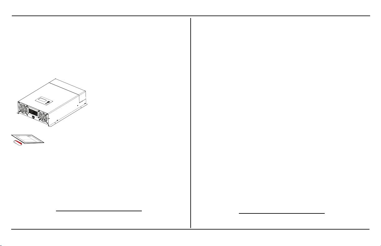
The Freedom X base package includes the following items:
n one Freedom X unit
n one Owner’s Guide and extra safety labels
n one pre-installed DC ground enclosure lug (not shown)
n one set of plastic bushings for large DC cables
n two AC knockout hole plugs
b
(not shown)
Figure 1 What’s In The Box
NOTE: If any of the items are missing, contact Xantrex or any
authorized Xantrex dealer for replacement. See Contact
Information on page ii.
a
(not shown)
Key Features
Power for Most Appliances
The Freedom X inverter provides up to 1000 watts (Freedom X
1000 120VAC 12VDC) or 2000watts (Freedom X 2000 120VAC
12VDC or 24VDC) or 3000watts (Freedom X 3000 120VAC
12VDC) of continuous utility grade, sine wave power derived from
a battery bank. It is designed to handle loads such as microwave
ovens, TVs, DVD/Blu-ray players, and power tools. In addition,
the Freedom X’s high-surge capability lets you handle many hardto-start loads, including full size residential refrigerators.
The built-in transfer switch automatically transfers between
inverter power and shore power from recreational facilities such as
boat docks or campsites to ensure power is always available.
Back-up Capability
If incoming shore power is interrupted by external events like
brownouts, the Freedom X automatically becomes an
independent power source3that supplies utility grade AC power to
your loads.
a
Available only to the Freedom X 2000 120VAC 12VDC only.
b
Available only to the Freedom X 3000 120VAC 12VDC only.
2 Freedom X Owner's Guide
3
Assumingthe i nverter is connected to a battery source with an adequate charge at the tim e of the power
interruption.
Page 17

Materials List
Comprehensive Protection
The Freedom X’s built-in protection features safeguard your
batteries (from unnecessary drain) such as the low battery voltage
alarm and shutdown and protect equipment such as a configurable
AC transfer speed.
n Selectable Low Battery Shutdown: The low battery
shutdown for the inverter can be manually selected by the
user from 10.1 to 12.8VDC (12VDC models) and from 20 to
25.6VDC (24VDC model).
n Low Voltage Shutdown Delay Timer: Configurable from 1
to 300seconds to reduce an unnecessary shutdown of
inverter operation such as during cranking or other brief but
heavy discharge of battery.
n Inverter Power Save: The Freedom X can be programmed
to automatically turn off after 1 to 25 hours of continued
operation of loads that are under 50watts. It is designed,
with LBCO (low battery cut off), to prevent the battery from
deep discharge.
Configurable AC Transfer Speed
The Freedom X allows two speed settings for the AC transfer from
Grid Mode to Battery Mode and vice versa which avoids nuisance
resetting of appliances. The normal transfer rate is for common
appliances and the faster transfer rate is designed for more
sensitive digital equipment like a desktop computer.
Overload Alarm and Shutdown
During Battery Mode (also called Inverter Mode), the Freedom X
automatically alerts you if the loads that are connected and
drawing power from the unit are close to approaching the
maximum operating limit. If so, the Freedom X automatically
shuts down when the maximum operating limit is exceeded. See
Troubleshooting Reference on page 72 for precautions.
Over temperature Alarm and Shutdown
During Battery Mode, the Freedom X automatically alerts you if it
is overheating and approaching the over-temperature shutdown
limit. The Freedom X automatically shuts down when the limit is
exceeded. See Troubleshooting Reference on page 72 for
precautions.
Ignition Control
The Freedom X provides two user-selectable options for ignition
control:
n Ignition Auto-on: The Freedom X can automatically turn
the inverter on and off in tandem with the vehicle's ignition
circuit or a manually operated remote switch.
n Ignition Lockout: The Freedom X features the ability to
inhibit the inverter from operating in the absence of a voltage
signal from a vehicle's ignition circuit. This is particularly
useful if the inverter is required to operate only when a
vehicle's engine is running.
975-0787-01-01 3
Page 18

Materials List
Configurable AC Output Frequency and Voltage
The Freedom X is factory set to 60Hz AC output frequency and
120V AC output voltage. It can be configured to 50Hz for use in
regions outside the USA and Canada. The AC voltage setting can
also be configured to either of three settings: 108, 110, or
120volts.
4 Freedom X Owner's Guide
Page 19

2 FEATURES
This section identifies the default settings and the hardware
features of the Freedom X Inverter.
This section includes:
Default Settings 6
AC/DC and GFCI Panel 8
Display Panel 10
Side Panel 11
975-0787-01-01 5
Page 20
Default Settings
Default Settings
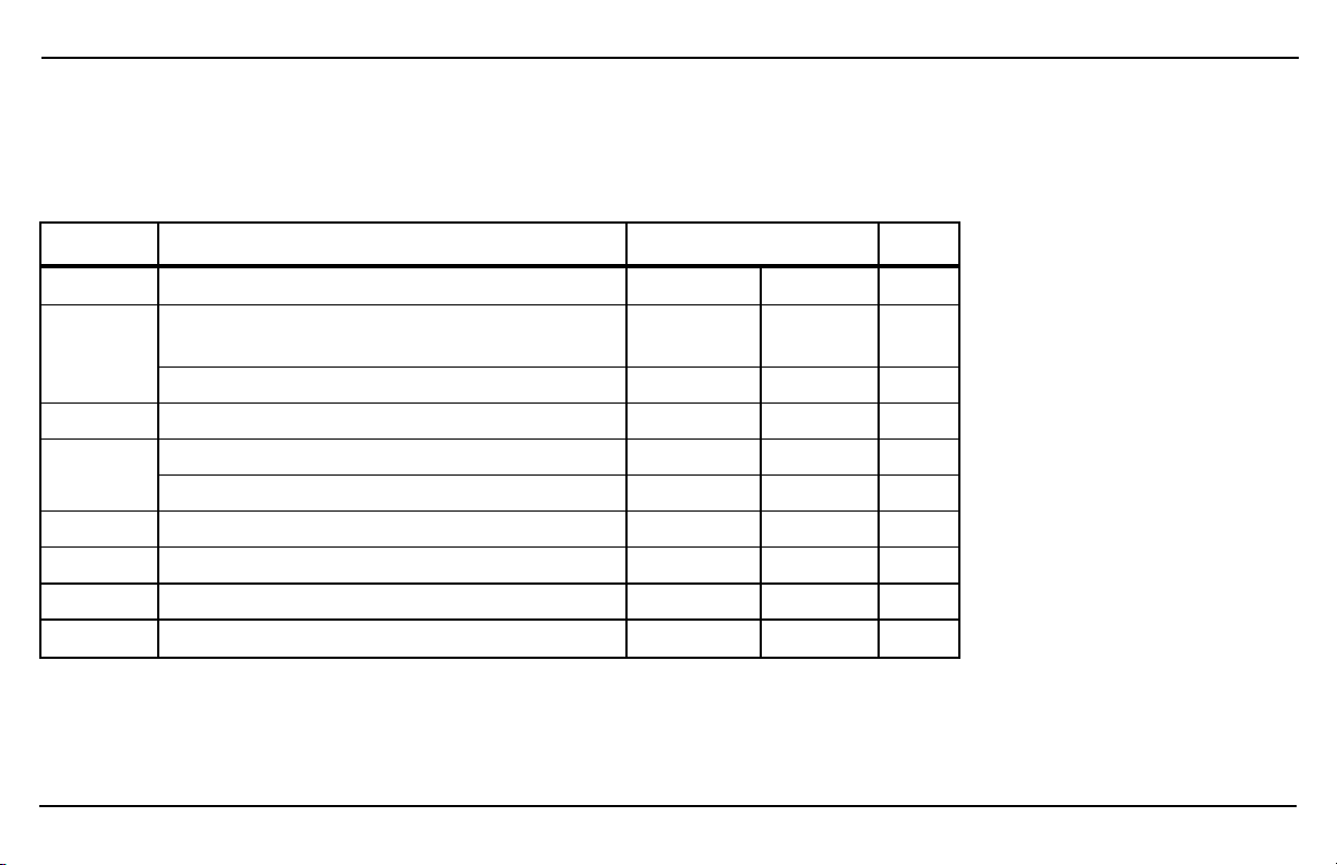
Table 1 lists the default settings for the Freedom X system.
You may record your settings in the right-hand column after you have configured the Freedom X.
Table 1Freedom X Default Values
Program Item Default Setting
01
02
03
04
05
06
07
08
6 Freedom X Owner's Guide
Inverter ignition control
Low battery cutoff (LBCO) voltage (12VDC
models)
Low battery cutoff (LBCO) voltage (24VDC model) 21.0 volts DC
LBCO shutdown delay timer 300seconds
LBCO recovery voltage (12VDC models) 13.1 volts DC
LBCO recovery voltage (24VDC model) 26.2 volts DC
Power save time 25 hours
Load sensing Disabled
Inverter output frequency 60Hz
Inverter output voltage 120 volts AC
Off
10.5voltsDC
Off
10.5
21.0
300
13.1
26.2
25
dis
60
120
Setting
Page 21
Default Settings
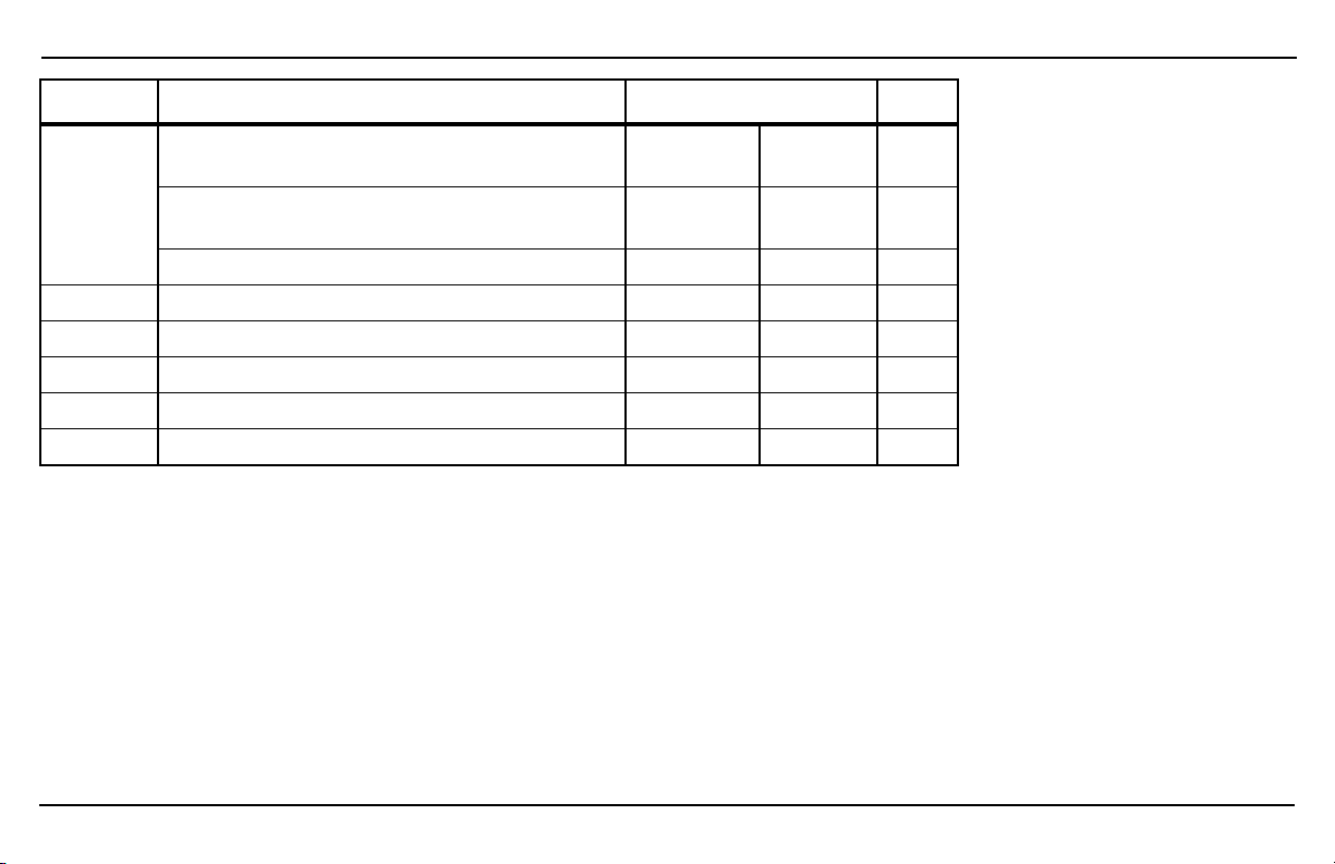
Program Item Default Setting
09
10
11
12
13
14
Inverter power limit
Freedom X 1000 120VAC 12VDC 1 kW
Freedom X 2000 120VAC 12VDC/24VDC
Freedom X 3000 120VAC 12VDC 3 kW
Inverter power limit timer 300seconds
Transfer mode Appliance
Utility AC under-voltage level 90 volts AC
Inverter fault recovery Manual
Audible alarm On
2 kW
1
2
3
300
APL
90
man
On
Setting
975-0787-01-01 7
Page 22
AC/DC and GFCI Panel
6
321
7
14 13
12
13
8
11
910
4
5
5
12
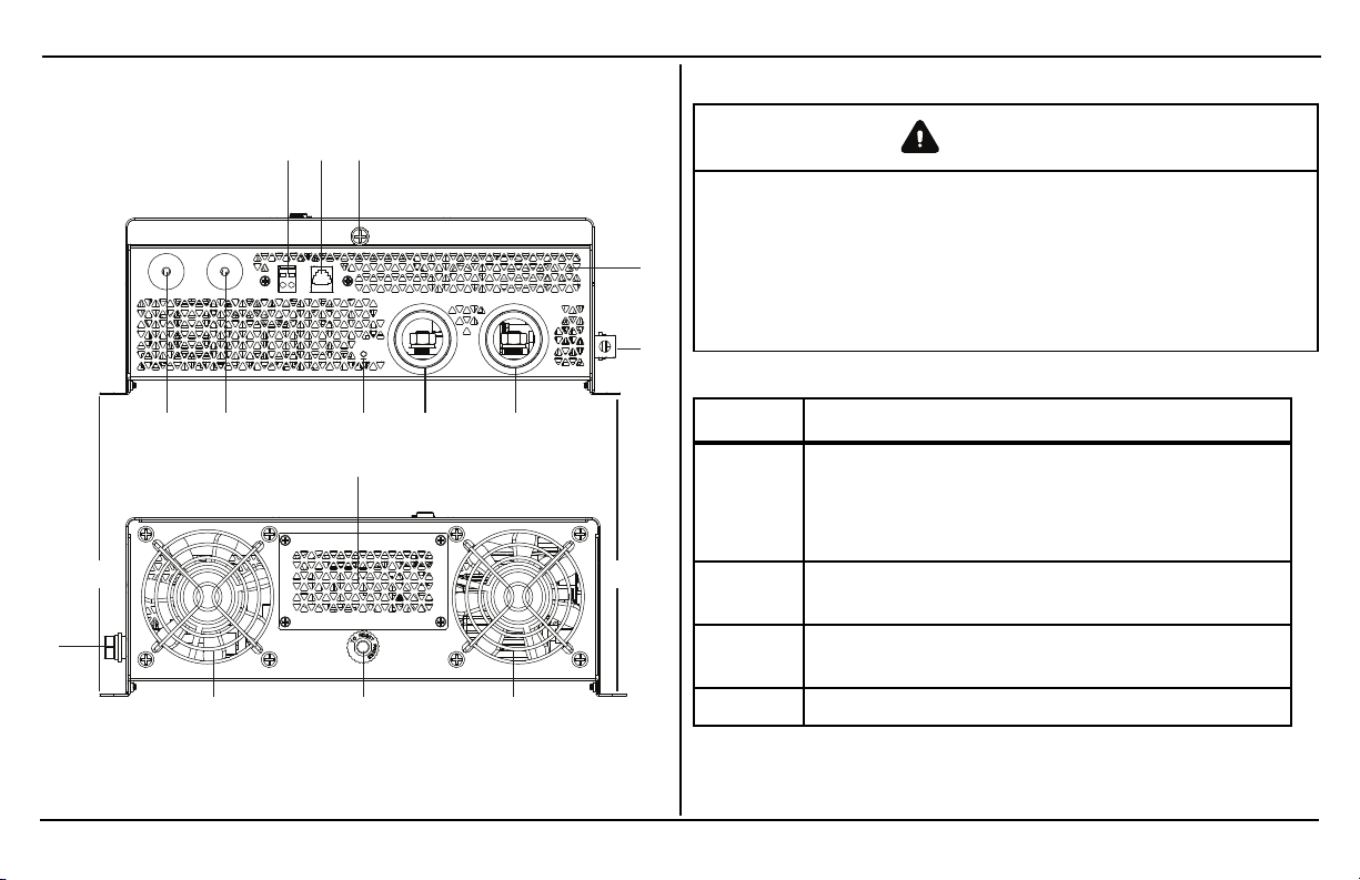
AC/DC and GFCI Panel
WARNING
ELECTRICAL SHOCK HAZARD
Use a torque screwdriver to tighten the captive nut panel screw to
5in-lb torque of force to ensure a proper ground connection and a
required tool access to the wiring compartment.
Failure to follow these instructions can result in death, serious
injury, or equipment damage.
Table 2AC/DC and GFCI Panel Features
Feature Description
ACC input terminal for connecting ignition control
1
2
3
4 Ventilation grille (openings) must not be obstructed.
wiring. Ignition Control Switch (ACC) for connecting
[ON (|)] and disconnecting [OFF (O)] the ignition
signal.
Remote port allows you to connect an accessory
remote control device.
Captive nut panel screw holds the wiring
compartment cover in place. See WARNING above.
Figure 2 AC/DC and GFCI Panel
8 Freedom X Owner's Guide
Page 23
AC/DC and GFCI Panel
Feature Description
Grounding lug provides a ground path for the
5
6
7
8 LED indicator for reverse DC polarity.
9
10
11
12
Freedom X chassis to the DC system ground. See
WARNING.
DC terminal opening for routing (–) negative DC
cable.
DC terminal opening for routing (+) positive DC
cable.
AC output terminal opening for routing AC output
wiring.
AC input terminal opening for routing AC input
wiring.
GFCI cover is removed when installing a qualified
GFCI device such as the optional GFCI kit (sold
separately; order PN: 808-9817).
Mounting flanges on both sides allow you to mount
the inverter permanently on deck or on a wall.
Feature Description
Ventilation grille (openings) must not be obstructed
for the proper operation of the cooling fan and
13
14
inverter. When the inverter is mounted, the
ventilation grille must not point up or down.
Cooling fans turn on when the internal temperature
reaches a set point temperature.
20 A supplementary protector with reset button
provides overload protection for the Freedom X
GFCI Kit (PN: 808-9817) (sold separately) option.
Press to recover from an overload condition. In a
hard wired installation, the supplementary protector
does not protect output wiring.
WARNING
ELECTRICAL SHOCK HAZARD
l
Use a torque screwdriver to tighten the bolt on the DC ground
lug to a torque of 23 in-lb (2.6 N-m) of force.
l
Apply an anti-corrosion compound to the copper wire prior to
connecting to the DC ground lug.
Failure to follow these instructions can result in death, serious
injury, or equipment damage.
975-0787-01-01 9
Page 24
Display Panel
1
OUTPUTBATTLOAD
kW
100%
25%
Hz
VA
%
kW
Hz
VA
%
C
INPUTBATTTEMP
AC
BYPASS
ERROR
OVERLOAD
CHARGING
888 888
88
2 3 4
5
Display Panel
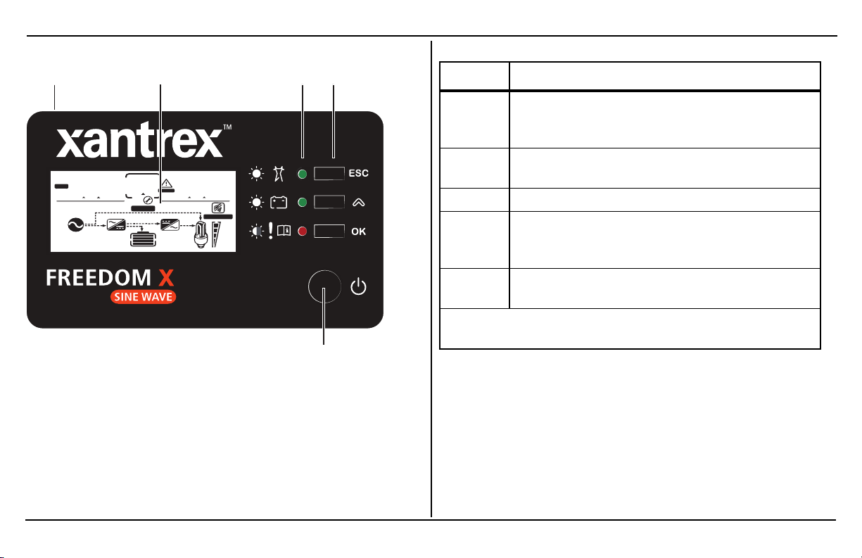
Figure 3 Display Panel
Table 3Display Panel Features
Feature Description
Display panel displays status information on the
1
2
3 Status LEDs indicate the mode of operation.
4
5
IMPORTANT: See Freedom XDisplay Panel on page 44 for
detailed information on the panel’s buttons.
screen. It is comprised of a display screen, LEDs,
select and power buttons.
Multi-function LCD screen shows status information
and error codes.
Three function buttons change status information
displayed on the screen. Also, changes inverter
settings.
Power button is pressed for turning on the unit. The
inverter turns on for the loads automatically.
10 Freedom X Owner's Guide
Page 25
Side Panel
1 2
4 3
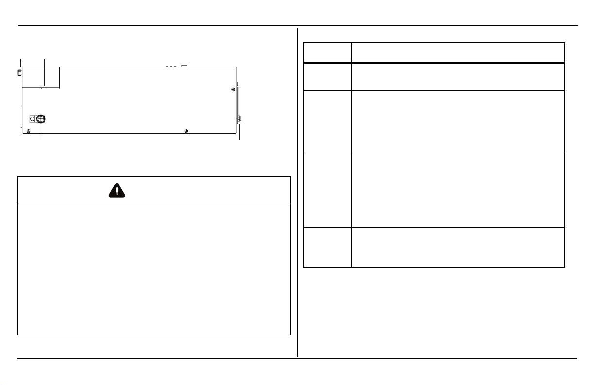
Side Panel
Figure 4 Side Panel
WARNING
ELECTRICAL SHOCK HAZARD
l
Use a torque screwdriver to tighten the captive nut panel
screw to 5in-lb torque to ensure a proper ground connection
and a required tool access to the wiring compartment.
l
Use a torque screwdriver to tighten the bolt on the DC ground
lug to a torque of 23 in-lb (2.6 N-m) of force.
l
Apply an anti-corrosion compound to the copper wire prior to
connecting to the DC ground lug.
Failure to follow these instructions can result in death, serious
injury, or equipment damage.
Table 4Side Panel Features
Feature Description
1
2
3
4
Captive nut panel screw holds the wiring
compartment cover in place. See WARNING above.
Wiring compartment cover protects the wiring
compartment from debris and keeps the cables
secure. Using the captive nut panel screw, the cover
can be opened and lifted out during wiring. See
WARNING on the left.
20 A supplementary protector with reset button
provides overload protection for the Freedom X
GFCI Kit (PN: 808-9817) (sold separately) option.
Press to recover from an overload condition. In a
hard wired installation, the supplementary protector
does not protect output wiring.
Grounding lug provides a ground path for the
Freedom X chassis to the DC system ground. See
WARNING.
975-0787-01-01 11
Page 26

This page is intentionally left blank.
Page 27

3 INSTALLATION
Please read this section for safety information and installation
instructions regarding your Freedom X.
This section includes:
Before You Begin the Installation 14
Installation Codes 15
Installation Tools and Materials 15
Basic Installation Procedures 16
Step 1: Designing the Installation 17
Step 2: Choosing a Location for the Unit 23
Step 3: Mounting the Unit 24
Step 4: Connecting the AC Input Wires 26
Step 5: Connecting AC Output to an Existing AC Circuit 31
Step 6: Connecting the DC Cables 33
Step 7: Connecting to Port(s) on the Freedom X 39
Step 8: Testing Your Installation 39
Marine Installation 41
Drip Shield Installation 42
975-0787-01-01 13
Page 28
Before You Begin the Installation
Before You Begin the
Installation
Before beginning your installation:
n Read this entire Installation section so you can plan the
installation from beginning to end.
n Assemble all the tools and materials you require for the
installation.
n Review the Important Safety Instructions on page v
n Be aware of all safety and electrical codes which must be
met.
WARNING
ELECTRICAL SHOCK AND FIRE HAZARD
l
All wiring should be done by qualified personnel to ensure
compliance with all applicable installation codes and
regulations.
l
Do not connect to AC and DC power sources during
installation. Disconnect from all power sources when
servicing.
l
Disable and secure all AC and DC disconnect devices and
automatic generator starting devices.
l
To prevent risk of fire, do not cover or obstruct ventilation
openings. Do not mount in a zero-clearance compartment.
Overheating may result.
Failure to follow these instructions can result in death, serious
injury, or equipment damage
14 Freedom X Owner's Guide
Page 29

Installation Codes
Installation Codes
Governing installation codes vary depending on the specific
location and application of the installation. Some examples
include the following:
n The U.S. National Electrical Code (NEC)
n The Canadian Electrical Code (CEC)
n The U.S. Code of Federal Regulations (CFRs)
n Canadian Standards Association/CSA Group (CSA) and the
RV Industry Association (RVIA) standards and codes for
installations in RVs
n The American Boat and Yacht Council (ABYC) standards
and US Coast Guard Regulations (33CFR183, Sub Part I)
for Marine installations in the U.S.
It is the installer’s responsibility to ensure that all applicable
installation requirements are met.
Installation Tools and Materials
You will need the following to install the Freedom X:
n Wire stripper
n Mounting (#2) screws or bolts
n #2 Phillips torque screwdriver
n 3mm slot long neck screwdriver for spring clamp AC
terminals
n Torque wrench for DC terminals (½" or 13mm socket
wrench)
n AC cable (that is, two-conductor-plus-ground cable), sized
appropriately for load and application
n ½" (or ¾") trade-size strain relief clamps (for the AC cable
clamp holesa)
n Wire nuts or crimp connectors for AC wire and appropriate
tools
n DC cable, sized appropriately for load and application
n Lugs for DC cables to fit5/
appropriate tools (like a crimping tool)
n AC and DC disconnects and over-current protective devices
" DC stud terminals as well as
16
a
Only the Freedom X 3000 120VAC 12VDC has the 3/4" trade-size knockout hole.
975-0787-01-01 15
Page 30
Basic Installation Procedures
Basic Installation Procedures
This section provides sample installation information as a guide
for your installation. For your convenience, the overall procedure
is divided into these main steps:
Step 1: Designing the Installation 17
Step 2: Choosing a Location for the Unit 23
Step 3: Mounting the Unit 24
Step 4: Connecting the AC Input Wires 26
Step 5: Connecting AC Output to an Existing AC Circuit 31
Step 6: Connecting the DC Cables 33
Step 7: Connecting to Port(s) on the Freedom X 39
Step 8: Testing Your Installation 39
NOTE: For marine applications, see additional installation
instructions on page 41.
16 Freedom X Owner's Guide
Page 31

Step 1: Designing the Installation
1
11
14
12
13
3
5
4
9
10
8
15
7
6
2
Most Freedom X installations share common components, and
some of these are briefly described in Step 1: Designing the
Installation.
Figure 5 shows some components and their relationship to each
other in a typical recreational vehicle or fleet vehicle installation.
Also, see "Marine Installation" on page41.
1 20-pin harness accessory Not applicable for t his product.
2 Equipment ground
3 Freedom X
4 DC fuse/disconnect/DC cir cuit breaker
5 12V/24V (as applicable) deep cycle battery
6 Battery isolator
7 Alternator
8 To engine
9 Equipment ground
10 Startingbattery
11 AC load panel
12 AC source panel
13 Selector switch
14 Shore power
15 Generator
Basic Installation Procedures
Figure 5 Typical Recreational Vehicle and Fleet Vehicle
Installation
975-0787-01-01 17
Page 32

Basic Installation Procedures
AC Shore Power
A source of 120 volts AC 60Hz sine wave alternating current
provides energy to pass power through to AC loads. This source
is usually the utility grid (power company) or an AC generator. An
automatic or manual AC source selector switch can be used to
switch between the multiple sources of shore power to the
Freedom X system.
The AC source feeding the Freedom X must have the neutral
conductor bonded to ground. When the inverter passes shore
power through, it will lift its internal bonding relay on the output and
will rely on the input being bonded in order to ensure that the power
delivered to a sub panel is properly bonded. See AC Shore Power
on page 18 for more information on bonding relay operation.
NOTE: Throughout this guide, the term “shore power” refers to AC
input power from a utility grid, generator, or other AC source.
AC Disconnect and Over-Current
Protection Device
Most safety requirements and electrical codes require the
Freedom X’s AC and DC inputs and outputs to be provided with
over-current protection (such as circuit breakers or fuses) and
disconnect devices.
AC Input
AC Output
The circuit breaker or fuse (connected through
hard wiring) that is used to supply the Freedom X
must be rated at no more than 30A and must be
approved for use on 120 volts AC branch circuits.
The wire used between the breaker and the
Freedom X input must be sized adequately to
carry current up to the rating of the input breaker
and in accordance with the electrical codes or
regulations applicable to your installation.
The circuit breaker or fuse must be rated at no
more than the rating of the input breaker in the
installation and must be approved for use on
120 volts AC branch circuits. The wire used
between the Freedom X and the AC output
breaker must be of adequate size to match the
AC input circuit breaker’s rating. The wiring
from each AC output breaker to each of the
loads must be adequately sized to carry the
current rating of the individual AC output
breaker.
18 Freedom X Owner's Guide
Page 33

Basic Installation Procedures
Disconnect
Devices
Each system requires a method of
disconnecting the AC circuits. If the overcurrent protection devices are circuit breakers,
they will also serve as the disconnects. If fuses
are used, separate AC disconnect switches will
be needed ahead of the fuses. These will have
to be a branch circuit rated for 120 volts AC and
have an appropriate current rating.
AC Distribution Panels
Most systems incorporate distribution centers both ahead of the
Freedom X (the AC source panel) and between the Freedom X
and the loads (the AC load panel). An AC source panel includes a
main circuit breaker, which serves as over-current protection and
as a disconnect for the AC shore power supply line. Additional
circuit breakers serve individual circuits, one of which serves the
Freedom X. The AC load panel can incorporate an AC output
circuit breaker and breakers for individual load circuits.
NOTICE
RISK OF INVERTER DAMAGE
Do not connect the Freedom X to a 120/240V, 3-pole, 4-wire circuit.
Failure to follow these instructions can result in equipment
damage.
AC Cabling
AC cabling includes all the wires and connectors between the AC
source and the Freedom X, as well as all cabling between the
Freedom X and the AC output panels, circuit breakers, and loads.
The type and size of the wiring varies with the installation and
load. For example, in high vibration environments, such as marine
or RV applications, wire nuts may not be acceptable, so crimp
splices would be required. In other applications, flexible multiplestrand wire may be required. Installation codes usually specify
975-0787-01-01 19
Page 34

Basic Installation Procedures
solid or stranded, overall size of the conductors, and type and
temperature rating of the insulation around the wire.
AC breakers and fuses must be sized to adequately protect the
wiring that is installed on the input and output AC circuits of the
Freedom X. All breakers and wiring must be sized and connected
in accordance with the electrical codes or regulations applicable to
your installation. Table 5gives some examples of wiring sizes
based on the U.S. National Electrical Code and the Canadian
Electrical Code. These examples are based on using a twoconductor-plus-ground cable rated at 75 °C, and assuming an
ambient temperature of up to 30 °C. Ensure that your breakers and
fuses have suitable temperature ratings for your wiring. Other
codes and regulations may also be applicable to your installation.
Table 5Required AC Wire Size vs Breaker Rating
Breaker Size
(amps)
Minimum Wire
Size
10A 15A 20A 30A
14AWG 14AWG 12AWG 10AWG
AC Output Neutral Bonding
The neutral conductor of the Freedom X’s AC output circuit (that
is, AC Output Neutral) is automatically connected to the safety
ground during inverter operation. When AC utility power is present
this connection is not present, so that the utility neutral (that is,
AC Input Neutral) is only connected to utility ground at your
source. This conforms to the National Electrical Code (NEC),
which requires that separately derived AC sources (such as
inverters and generators) have their neutral conductors tied to
ground in the same way that the neutral conductor from the utility
is tied to ground in only one place. Check the regulations for your
specific application to ensure that the installation will comply with
the necessary requirements. In other words, the AC Input Neutral
ground bonding and Output Neutral ground bonding must be
isolated from each other.
AC Grounding
As per UL458 SA29.5, for all permanently connected marine
inverters: The Freedom X should be connected to a grounded,
metal, permanent wiring system. Also, make sure that an AC
ground wire is connected to the AC ground terminal on the unit. Do
not just connect the line and neutral wires.
All connections to the unit should comply with all local codes and
ordinances.
20 Freedom X Owner's Guide
Page 35

Basic Installation Procedures
DC Cabling
This includes all the cables and connectors between the batteries,
the DC disconnect and over-current protection device, and the
Freedom X. Most mobile installations require multi-strand
insulated cables for flexibility and durability in high vibration
environments and require disconnects and over-current devices.
Electrical wiring sizes in North America are indicated by AWG
notation. In other parts of the world, the metric system is used.
Under the AWG standard, a larger gauge number indicates a
smaller wire diameter. Wire size is usually marked on the larger
sized cables. Table 6specifies the minimum recommended DC
cable size and maximum fuse size for the Freedom X. The DC
cables must be copper and must be rated 75 °C minimum.
The cables should be terminated with lugs that fit the DC stud
terminals snugly (
5
/
" hole size).
16
Table 6Required Cable Sizes
Cable Length:
Inverter
Battery to Inverter
(one way)
Freedom X
1000 120VAC
12VDC
Freedom X
2000 120VAC
12VDC
Freedom X
3000 120VAC
12VDC
Freedom X
2000 120VAC
24VDC
NOTE:It is not recommended using a cable longer than 5 feet
(1.5 meters) in each direction. North American cable sizes above
are based on the US National Electrical Code Table 310.17 75°C cables, assuming an ambient temperature of 30 °C cables.
Less than 5 feet
(1.5 meters)
Less than 5 feet
(1.5 meters)
Minimum
Cable
Size
No. 2 AWG 150 ADC
No. 2/0
AWG
No. 4/0
AWG
No. 2 AWG 150 ADC
Maximum
battery
Fuse Size
250 ADC
350 ADC
IMPORTANT: Using the correct cable size is critical to achieving
the rated performance of the Freedom X unit. When starting a
heavy load the Freedom X can draw current surges from the
battery of up to 400A (in 12VDC models). If the DC wiring is too
975-0787-01-01 21
Page 36

Basic Installation Procedures
small the voltage drop from this surge will result in a voltage at the
Freedom X terminals that is too low for the Freedom X to operate
correctly. The Freedom X may appear to operate correctly with
smaller cables until a heavy load such as a microwave or
refrigerator attempts to start - then the unit may work correctly
sometimes and not work correctly other times.
DC Disconnects and Over-Current Devices
The DC circuit from the battery to the Freedom X must be
equipped with a disconnect and over-current device. This usually
consists of a circuit breaker, a “fused-disconnect”, or a separate
fuse and DC disconnect. Do not confuse AC circuit breakers
with DC circuit breakers. They are not interchangeable. The
rating of the fuse or breaker must be matched to the size of cables
used in accordance with the applicable installation codes. The
breaker or disconnect and fuse should be located as close as
possible to the battery, in the positive cable. Applicable codes
may limit how far the protection can be from the battery.
Batteries
The Freedom X uses 12-volt battery banks typically, or 24-volt
battery banks for the 24VDC model. Every Freedom X system is
recommended to have a deep-cycle battery or group of batteries
with a total capacity of 100Ah or more which provides the DC
current that the Freedom X converts to AC.
Ground Fault Circuit Interrupters (GFCIs)
A GFCI is a device that de-energizes a circuit when a current to
ground exceeds a specified value that is less than that required to
blow the circuit breaker. GFCIs are intended to protect people
from electric shocks and are usually required in wet or damp
locations.
Installations in marine and recreational vehicles require GFCI
protection of branch circuits connected to the AC output of the
Freedom X.
The Freedom X GFCI Kit (PN: 808-9817) (sold separately) option
is available to use with the Freedom X inverter unit.
22 Freedom X Owner's Guide
Page 37

Step 2: Choosing a Location for the Unit
WARNING
FIRE AND EXPLOSION HAZARDS
l Do not install the Freedom X in compartments containing
batteries or flammable materials, or in locations that require
ignition-protected equipment. This includes any space
containing gasoline-powered machinery, fuel tanks, or joints,
fittings, or other connections between components of the fuel
system. This equipment contains components that tend to
produce arcs or sparks.
l Do not install on or over combustible surfaces.
l Do not cover or obstruct the ventilation openings.
l Do not install the Freedom X in a zero-clearance
compartment. Overheating may result.
Failure to follow these instructions can result in death, serious
injury, or equipment damage.
The Freedom X should only be installed in locations that meet the
following requirements:
n Dry. Do not allow water or other fluids to drip or splash on
the Freedom X. Do not mount the Freedom X in an area
subject to splashing water or bilge water.
n Cool. Normal air temperature should be between -4°F and
104°F (-20°C and 40°C)—the cooler the better.
Basic Installation Procedures
n Ventilated. Allow at least 5 inches of clearance at the fan
end of the Freedom X for air flow, 1 inch on each side, and 2
inches at the wiring access (AC and DC) end. The more
clearance for ventilation around the unit, the better the
performance. Do not allow the ventilation openings on the
ends of the unit to become obstructed.
n Safe. Do not install the Freedom X in the same
compartment as batteries or in any compartment capable of
storing flammable liquids like gasoline.
n Close to the battery compartment and the AC source
and load panels. Avoid excessive cable lengths (which
reduce input and output power due to wire resistance). Use
the recommended cable lengths and sizes, especially
between the battery banks and the Freedom X.
n Protected from battery acid and gases. Never allow
battery acid to drip on the Freedom X or its wiring when
reading specific gravity or filling the battery. Also do not
mount the unit where it will be exposed to gases produced
by the batteries. These gases are very corrosive, and
prolonged exposure will damage the Freedom X.
975-0787-01-01 23
Page 38

Basic Installation Procedures
A
B
C
Step 3: Mounting the Unit
To mount the Freedom X:
1. Remove the Freedom X from its shipping container, verify
that all components are present, and record relevant product
information on “Information About Your System” in the
Owner’s Guide.
2. Select an appropriate mounting location and orientation (see
Figure 6 ). To meet regulatory requirements, for use in onland applications, the Freedom X must be mounted in one of
the following orientations:
a. Under a horizontal surface (see A)
b. In a horizontal position on a vertical surface (see B)
NOTE: For marine installations, only this orientation is
allowed, due to the probability of moisture finding
access into the enclosure.
c. On a horizontal surface (see C)
Figure 6 Approved Mounting Orientations
3. Mark the desired number of mounting holes on the wall by
placing the unit on the wall.
4. Pilot-drill the mounting holes.
5. Fasten the Freedom X to the mounting surface. If you are
mounting the unit on a wall or bulkhead, use #12 or #14 panhead wood or sheet metal screws to secure it to the framing
behind the wall or bulkhead. Alternatively, use nut inserts
and ¼"-20 machine screws.
24 Freedom X Owner's Guide
Page 39

Basic Installation Procedures
1
Connecting the Equipment Ground
WARNING
ELECTRIC SHOCK HAZARD
Never operate the Freedom X without properly connecting the
equipment ground. A shock and energy hazard could result from
improper grounding.
Failure to follow these instructions can result in death, serious
injury, or equipment damage.
The Freedom X has a ground lug on the side of the unit as shown
in Connecting the Equipment Ground. Follow the guidelines in
Connecting the Equipment Ground to connect the inverter’s
chassis to the ground.
Figure 7 DC Panel Connections
Grounding Locations
You must connect the equipment ground lug to a grounding
point—usually the vehicle’s chassis or DC negative bus ground—
using recommended copper wire (if insulated then green insulation
with or without one or more yellow stripes) or larger.
Make sure to tighten the bolt on the DC ground lug to a torque of
23 in-lb (2.6N-m) of force. Apply an anti-corrosion compound to
the copper wire prior to connecting to the DC ground lug.
1 DC grounding lug
975-0787-01-01 25
Page 40

Basic Installation Procedures
For recommended equipment ground cable size, see below.
Table 7Equipment DC ground cable size
Step 4: Connecting the AC Input Wires
Minimum equipment ground cable
Application
size (Stranded copper cable is
required)
Recreational
Vehicle
Marine
NOTE: There are no restrictions on length for the equipment
ground cable but try to make it as short as practical to a secure
chassis connection. In general, the equipment ground cable size
must not be smaller than one AWG size than the supply cable.
b
c
b
Based on US National Electrical C ode NF PA70, Article 551, par. 551-20c and ANSI/RVIA LV, § 2-5.1.
c
Based on ABYC E-11 § 11.16 and A-31 § 31.6.5.
No. 8 AWG
No. 3 AWG (Freedom X 1000 120VAC
12VDC)
No. 1/0 AWG (Freedom X 2000 120VAC
12VDC)
No. 2/0 AWG (Freedom X 3000 120VAC
12VDC)
No. 3 AWG (Freedom X 2000 120VAC
24VDC)
WARNING
ELECTRIC SHOCK AND FIRE HAZARDS
Make sure wiring is disconnected from all electrical sources before
handling. All wiring must be done in accordance with local and
national electrical wiring codes. Do not connect the output
terminals of the Freedom X to any incoming AC source.
Failure to follow these instructions can result in death, serious
injury, or equipment damage.
General AC Wiring Considerations
AC Wiring Connectors
Where applicable, connect AC wires with crimp-on splice
connectors. The amount of insulation you strip off individual wires
will be specified by the connector manufacturer and is different for
different types of connectors.
AC and DC Wiring Separation
Do not mix AC and DC wiring in the same conduit or panel. Where
DC and AC wires must cross, make sure they do so at 90°to one
another. Consult applicable codes for details about DC and AC
wiring in close proximity to each other.
26 Freedom X Owner's Guide
Page 41

AC Wiring and GFCIs
You can plug loads of up to 20amps directly into the GFCI
receptacle on the front panel of the Freedom X. If installed, you
can also connect the inverter to an existing AC installation and
then plug loads into GFCI receptacles connected to that circuit.
If you plan to use the Freedom X GFCI kit on the unit, proceed to
General AC Wiring Considerations on page 26.
AC wiring includes all the wires and connectors between the AC
source and the Freedom X and all wiring between the inverter, the
AC panels, GFCI, and circuit breakers. The type and size of the
wiring varies with the installation and load. For some RV
applications, flexible multiple-strand copper wire is required.
AC wiring must be sized appropriately using conductors with
insulation rated at least 75°C to carry full load current on the input
and output AC circuits in accordance with the electrical codes or
regulations applicable to your installation. Table 8is based on the
U.S. National Electrical Code and the Canadian Electrical Code,
assuming two-conductor-plus-ground cable, using 75°C wiring, at
an ambient temperature of 30°C. Other codes and regulations
may be applicable to your installation.
Basic Installation Procedures
Table 8Required AC wire size vs. required breaker rating
Freedom X
Required Breaker
Size (amps)
30 A maximum
20A maximum through
a GFCI
Required Wire
Size
10 AWG
The AC input terminal is located inside the unit through the front
panel’s ½" trade-size hole (or ¾" trade-size knockoutd) and is
labeled properly as AC IN or AC INPUT. The unit comes with
spring clamp-type terminals where individual wires can be
attached securely.
NOTICE
EQUIPMENT DAMAGE
Make sure the wires are connected properly. The AC wiring
terminal blocks are split into input and output sections.
Failure to follow these instructions can result in equipment
damage.
When making the AC input and AC output connections, observe the
correct color code for the appropriate AC wire, as described inTable
9 below.
d
Available only to Freedom X 3000 120VAC 12VDC.
975-0787-01-01 27
Page 42

Basic Installation Procedures
Table 9Color codes for typical AC wiring
Color AC Wire
Black/Red/Brown Line
White/light blue Neutral
Green, green/yellow, or bare
copper
Ground (Earth)
NOTICE
REVERSE POLARITY DAMAGE
Make sure the wires are connected properly. Improper connections
(connecting a line conductor to a neutral conductor, for example)
will cause the Freedom X to malfunction and may permanently
damage the inverter. Damage caused by a reverse polarity
connection is not covered by your warranty.
Failure to follow these instructions can result in equipment
damage.
Wiring Knockouts
When installing wires to the AC terminals, the AC input and output
holes are provided to accommodate ½" trade-size strain relief
clamps. If larger cables and strain relief clamps are needed,
remove the ¾" trade-size knockout ringse.
e
Available only to Freedom X 3000 120VAC 12VDC.
Make sure to seal the open ½" trade-size holes with the supplied
knockout plugs by placing the plugs and firmly pressing them into
the holes.
NOTICE
EQUIPMENT DAMAGE
Install the supplied AC knockout plugs over the knockout holes
when not used for wiring to prevent objects and other material from
entering the unit.
Failure to follow these instructions can result in equipment
damage.
AC Input Connections
To make a permanent connection to existing AC wiring:
1. Ensure AC and DC power sources are turned off.
2. Install the required circuit breaker in the AC distribution
panel supplying AC power to the unit.
3. Remove the wiring compartment cover by loosening the
captive nut panel screw [1] and lifting the cover up and out.
WARNING
ELECTRIC SHOCK HAZARD
Use a screwdriver to loosen the captive nut panel screw.
Failure to follow these instructions can result in death, serious
injury, or equipment damage.
28 Freedom X Owner's Guide
Page 43

Figure 8 Loosening the captive nut panel screw
1
N
L
G
N LG N LG
2
1
3
4
5
1 Captivenut panel screw
4. Strip a single AC input wire, as appropriate. Strip 10 mm off
the ends of each of the three the wires (tin the exposed
copper wire with lead-free solder using a soldering iron).
5. Remove the knockout and install a ½" (or ¾"f) strain relief
clamp.
6. Route the wires through the strain relief clamp (not shown in
the figure).
Basic Installation Procedures
Figure 9 Routing the wires
1 step8a
2 step8b
3 step8c
4 10mm
5 to circuit breaker
NOTE: AC input hole - install a strain relief clamp (not shown).
7. Locate the Neutral, Ground and Line terminals on the AC
input terminal labeled as N, G, and L respectively.
f
Available only to Freedom X 3000 120VAC 12VDC.
975-0787-01-01 29
Page 44

Basic Installation Procedures
N
L
G
8. Connect each AC wire into its corresponding terminal on the
no-tool cage clamp terminal block.
a. Lift the terminal lever (as shown in the previous figure).
b. Insert the wire fully into the open slot.
c. Lower the terminal lever to secure the wire in the slot.
9.
Make sure that each AC wire is matched and connected to
the Neutral (N), Ground(G), and Line (L) connections.
10. Tighten the strain relief clamp to secure the wires.
11. Replace the wiring compartment cover onto the unit (using a
#2 Phillips torque screwdriver - see WARNING), if you are
not connecting other wires such as for the AC Output.
Otherwise, keep the AC compartment open and proceed to
the next step.
WARNING
ELECTRICAL SHOCK HAZARD
Use a torque screwdriver to tighten the captive nut panel screw to
5in-lb torque of force to ensure a proper ground connection and a
required tool access to the wiring compartment.
Failure to follow these instructions can result in death, serious
injury, or equipment damage.
12. Connect the other end of the wires to the circuit breaker in
the AC distribution panel supplying AC power to the unit.
30 Freedom X Owner's Guide
Page 45

Basic Installation Procedures
Step 5: Connecting AC Output to an Existing AC Circuit
WARNING
ELECTRIC SHOCK AND FIRE HAZARDS
Make sure wiring is disconnected from all electrical sources before
handling. All wiring must be done in accordance with local and
national electrical wiring codes.
Failure to follow these instructions can result in death, serious
injury, or equipment damage.
NOTICE
EQUIPMENT DAMAGE
l Do not connect any AC source (such as a generator or
utility power) to the AC output wiring of the Freedom X.
l The Freedom X will not operate if its output is connected to
AC voltage from another source, and potentially hazardous
or damaging conditions may occur. These conditions can
occur even if the inverter is off.
Failure to follow these instructions can result in equipment
damage.
Do not connect the Freedom X to an AC branch circuit that has
high-power consumption loads.
The Freedom X will not operate electric heaters, air conditioners,
stoves, and other electrical appliances that consume more than
its rated watts.
A manufacturer-tested and approved GFCI must be connected to
the Freedom X AC output, and GFCI protection must be provided
on every receptacle connected to the AC hard wired installation.
Other types may fail to operate properly when connected to the
Freedom X. See Ground Fault Circuit Interrupters (GFCIs) on
page 22.
975-0787-01-01 31
Page 46

Basic Installation Procedures
N
L
G
N LG N LG
2
1
3
4
5
AC Output Connections
Figure 10 Routing the wires
2. Install the required circuit breaker in the inverter distribution
panel receiving AC power from the inverter.
3. Remove the wiring compartment cover, if not already done
from AC Output Connections on page 32.
WARNING
ELECTRIC SHOCK HAZARD
Use a screwdriver to loosen the captive nut panel screw.
Failure to follow these instructions can result in death, serious
injury, or equipment damage.
4. Strip a single AC output wire, as appropriate. Strip 10 mm off
the ends of each of the three the wires (tin the exposed
copper wire with lead-free solder using a soldering iron).
5. Remove the knockout and install a ½" (or ¾"g) strain relief
clamp.
1 step7a
2 step7b
3 step7c
4 10mm
5 to circuit breaker
NOTE: AC output hole - install a strain relief cl amp (not shown).
To make a permanent connection to existing AC wiring:
1. Ensure AC and DC power sources are turned off, if not
already done from AC Output Connections on page 32.
32 Freedom X Owner's Guide
6. Route the wires through the strain relief clamp (not shown in
the figure).
7.
Connect each AC wire into its corresponding terminal on the
no-tool cage clamp terminal block.
a. Lift the terminal lever (as shown on the figure).
b. Insert the wire fully into the open slot.
c. Lower the terminal lever to secure the wire in the slot.
8.
Make sure that each AC wire is matched and connected to
g
Available only to Freedom X 3000 120VAC 12VDC.
Page 47

the Neutral (N), Ground(G), and Line (L) connections.
N
L
G
9.
Tighten the strain relief clamp to secure the wires.
10.
Replace the wiring compartment cover (using a #2 Phillips
torque screwdriver - see WARNING), if you are finished with
connecting all the AC wires in the unit (and installing the
GFCI).
WARNING
Basic Installation Procedures
Step 6: Connecting the DC Cables
NOTICE
REVERSE POLARITY
l
Check cable polarity at both the battery and the Freedom X
before making the final DC connection. Positive must be
connected to positive; negative must be connected to
negative. Check to see if the reverse polarity LED (see Step
6: Connecting the DC Cables) is not illuminated.
l
Reversing the positive and negative battery cables will blow
a fuse in the Freedom X and void your warranty.
Failure to follow these instructions can result in equipment
damage.
ELECTRICAL SHOCK HAZARD
Use a torque screwdriver to tighten the captive nut panel screw to
5in-lb torque of force to ensure a proper ground connection and a
required tool access to the wiring compartment.
Failure to follow these instructions can result in death, serious
injury, or equipment damage.
11. Connect the other end of the wires to a circuit breaker in the
FIRE HAZARD
Use only copper wire rated 75 °C minimum. Make sure all DC
connections are tight to a torque of 71–80 in-lb (8–9Nm) of force.
Loose connections will overheat.
Failure to follow these instructions can result in death, serious
injury, or equipment damage.
WARNING
inverter distribution panel.
Follow the procedure given below to connect the battery leads to
the terminals on the DC end. The cables should be as short as
975-0787-01-01 33
Page 48

Basic Installation Procedures
1 2 3
possible and large enough to handle the required current, in
accordance with the electrical codes or regulations applicable to
your installation. Table 6specifies the minimum DC cable size
and maximum fuse size for the Freedom X.
If at all possible, minimize routing your DC cables through an
electrical distribution panel, battery isolator, or other device that
will cause additional voltage drops which can degrade the
inverter’s ability to operate the loads.
Figure 11 shows the DC end for your reference. The reverse
polarity LED will light up when the DC cables were reversed
during installation. Reversing the connections may void the
warranty.
Figure 11 DC End
1 reverse polarity LED
2 positive (+)
3 negative ( –)
To make the DC connections:
1. Make sure the inverter is off and no AC or DC is connected
to the unit.
2. Remove the wiring compartment cover by loosening the
captive nut panel screw.
WARNING
ELECTRIC SHOCK HAZARD
Use a screwdriver to loosen the captive nut panel screw.
Failure to follow these instructions can result in death, serious
injury, or equipment damage.
3. Loosen the DC terminal nuts from the terminal bolts and set
them aside for later.
4. Strip ½" (13 mm) to ¾" (19 mm) insulation from one end of
each cable. The amount stripped off will depend on the
terminals chosen.
5. Attach the connectors that will secure the cables to the
battery, to the disconnect/battery selector switch, and the
fuse block. The connectors you use must create a
permanent, low-resistance connection. It is recommended
to use approved and certified cable ring lugs. Use the tool
recommended by the terminal manufacturer. Make sure no
stray wires protrude from the lug or terminal.
NOTE: You may find it more convenient to have the cable
lugs attached by the company that sells you the cable and/or
connectors.
34 Freedom X Owner's Guide
Page 49

6. Strip ½" (13 mm) to ¾" (19 mm) of insulation from each
cable end that will be connected to the inverter cable. The
amount stripped off will depend on the terminals chosen.
7. Attach the cable ring lug that will join the cable to the inverter
DC terminal. Cover the lug stem with heat shrink insulation
(see Step 6: Connecting the DC Cables) to ensure that the
lug does not touch the enclosure.
8. Install a fuse and fuse holder in the cable that will be used for
the positive side of the DC circuit. The fuse must:
a. be as close to the battery positive terminal as possible
b. be rated for DC circuits
c. have an Ampere Interrupting Capacity (AIC) that
exceeds the short-circuit current available from the
battery (that is, Class T fuse)
9. To prevent sparking when making the connection, ensure
the disconnect/battery selector switch is off.
10. Route the positive cable through the left side strain relief
clamp and attach the cable lug on the positive cable to the
positive DC terminal on the inverter.
11. Fasten the DC terminal nut (set aside earlier) to the terminal
bolt. Tighten the nut to a torque of 71–80 in-lb (8–9 N-m) of
force. Do not overtighten. Make the connection snug enough
so the cable lug does not move around on the DC terminal.
Center it through the DC knockout hole and do not let it
touch the edge. See Step 6: Connecting the DC Cables on
page 33.
Basic Installation Procedures
WARNING
ELECTRICAL SHOCK HAZARD
l
Tighten the nuts on the DC terminals properly. Loose
connections cause excessive voltage drop and may cause
overheated wires and melted insulation.
l
Do not over-tighten the nut on the DC input terminals
because damage to the DC input terminals may result. Use a
torque screwdriver to tighten the nut to a maximum torque of
80 in-lb (9 N-m) of force.
Failure to follow these instructions can result in death, serious
injury, or equipment damage.
NOTICE
REVERSE POLARITY
l
Check cable polarity at both the battery and the Freedom X
before making the final DC connection. Positive must be
connected to positive; negative must be connected to
negative. Check to see if the reverse polarity LED (see Step
6: Connecting the DC Cables) is not illuminated.
l
Reversing the positive and negative battery cables will blow
a fuse in the Freedom X and void your warranty.
Failure to follow these instructions can result in equipment
damage.
975-0787-01-01 35
Page 50

Basic Installation Procedures
1
2
3
4
5
6
7
Figure 12 DC Cable Connections
1 enclosure outline( DC compartment side view),
2 DC terminal nut
3 DC nut lock washer
4 cable ring lug
5 DC terminal
6 DC knockout hole
7 DC cable with heat shrink insulation covering the lug stem
NOTE: The D C cable lug stem must be fully insulatedwith the heat shrink.
WARNING
FIRE HAZARD
Do not complete the next step if flammable fumes are present.
Explosion or fire may result if the disconnect/battery selector switch
is not in the off position. Thoroughly ventilate the battery
compartment before making this connection.
Failure to follow these instructions can result in death, serious
injury, or equipment damage.
13. Route the negative cable through the right side strain relief
clamp and connect the cable from the negative post of the
battery to the negative DC terminal of the inverter.
14. Fasten the DC terminal nut (set aside earlier) to the terminal
bolt. Tighten the nut to a torque of 71–80 in-lb (8–9 N-m) of
force. Do not overtighten. Make the connection snug enough
so the cable lug does not move around on the DC terminal.
Center it through the DC knockout hole and do not let it
touch the edge.
15. Replace the wiring compartment cover by tightening the
captive nut panel screw. See the following electrical shock
hazard warning.
12. Before proceeding, double check that the cable you have
just installed connects the positive DC terminal of the
inverter to the disconnect/battery selector switch, fuse
holder, and that the other end of the fuse holder is connected
to the positive terminal of the battery.
36 Freedom X Owner's Guide
Page 51

WARNING
ELECTRICAL SHOCK HAZARD
Use a torque screwdriver to tighten the captive nut panel screw to
5in-lb torque of force to ensure a proper ground connection and a
required tool access to the wiring compartment.
Failure to follow these instructions can result in death, serious
injury, or equipment damage.
DC Grounding
To connect the DC ground:
1. The equipment grounding lug (DC ground lug) on the DC end
of the Freedom X is used to connect the chassis of the
Freedom X to your system’s DC negative connection or
grounding bus point as required by electrical regulations.
2. Use copper wire that is either bare or provided with green
insulation. Do not use the DC ground lug for your AC
grounding. See the AC wiring instructions in this section.
3. Follow the guidelines below that correspond to the specific
type of installation. These guidelines assume you are using
the DC supply cable and fuse sizes recommended in this
guide. If you are using different sizes, refer to the applicable
installation code for DC grounding details.
4. See Figure 7 for the location of the DC ground lug. Make
sure to tighten the bolt on the DC ground lug to a torque of
23in-lb (2.6N-m) of force. Apply an anti-corrosion
compound to the copper wire prior to connecting to the DC
ground lug.
Basic Installation Procedures
Recreational Vehicle
Use 8AWG minimum-sized, stranded copper wire and connect it
between the Chassis Ground lug and the vehicle’s DC grounding
point (usually the vehicle chassis or a dedicated DC ground bus).
See regulatory references below.
Marine
Use copper wire that is bare or has insulation rated minimum
105°C, and connect it between the Chassis Ground lug and the
boat’s DC grounding bus or engine negative bus. For the Freedom
X 1000 120VAC 12VDC and Freedom X 2000 120VAC 24VDC,
use a wire of gauge 3AWG minimum. For the Freedom X 2000
120VAC 12VDC, use a wire of gauge 1/0AWG minimum. For the
Freedom X 3000 120VAC 12VDC, use a wire of gauge 1/0AWG
minimum. See regulatory references below.
Regulatory
references
For DC voltagesystems under 50VDC in an RV installation, an 8AWG copper
bonding conductor would be acceptable for the inverter enclosure ground bonding
only per U L458 §63.6; §30.10standard [≤ 150m V @30A connection, per §63.9;
§63.10] and per ANSI/RVIA LV code§2-5.1 BondingVoltageConverter
Enclosures. The "house" battery system must, however, be groundbonded per
ANSI/RVIA LV code §2-4 Auxiliary Battery Gr ounding; and
For DC voltagesystems under 50VDC in a m arine installation, [UL458 §SA7.2]
a DC Groundingconductor shall not be smaller thanone size under that r equired
for current carr ying conductors supplying the device per ABYC E-11 §11.16.2 but
not less than 8AWG [USGC 46 CFR §111.05-31].
975-0787-01-01 37
Page 52

Basic Installation Procedures
Connecting to ACC Signal
To enable ig nit ion control:
1. Ensure that AC and DC power are both OFF.
2. Ensure the vehicle’s ignition is turned to OFF position. It is
highly recommended to remove battery power by
disconnecting the vehicle's battery cables. Refer to the
vehicle’s user manual for proper instructions on how to
disconnect the battery cables.
3. Locate the vehicle's ignition control wire from the vehicle’s
ignition circuit. This wire must be fused appropriately at no
more than 5amps. Refer to the vehicle’s user manual for
guidance.
4. Locate the ACC input (ignition signal input) terminal on the
right side of the connector. The left terminal is not used at
this time. See Figure 13
Figure 13 Ignition signal (ACC) input terminal
5. Using a 3mm slot long neck screwdriver, push into the
rectangular slot to release the spring clamp.
6. Insert the ignition control wire into the round ACC input
terminal slot.
7. Pull the screwdriver out to engage the spring clamp and
secure the wire to the terminal.
Description of Ignition Control Features
For information about the features and instructions on changing
the ignition control features, see Operation on page 43.
Table 10Ignition Control Features
This setting allows the inverter to operate
(Battery mode) automatically when an
Ignition Auto-
on (ATO)
ignition control wire is connected to the
ACC input and a valid ignition signal is
constantly detected. The inverter works in
tandem with the vehicle’s ignition circuit.
This setting allows the inverter to
operate (Battery mode) when an ignition
control wire is connected to the ACC
Ignition Lock-
out (LOt)
input terminal and a valid ignition signal
is constantly detected.
When enabled, you have to manually
press the Power button on the display
panel to operate the inverter.
To completely disable the ignition control
Off (OFF)
features do the following:
Set Ignition Control to Off (OFF) using the
Select buttons on the Display panel.
38 Freedom X Owner's Guide
Page 53

Basic Installation Procedures
Step 7: Connecting to Port(s) on the Freedom X
Connecting to the Remote Port
The Freedom X can accommodate the Freedom X Remote Panel
with cable (PN: 808-0817-01) (sold separately; comes with 25ftcable) or the Freedom X Remote Panel unit (PN: 808-0817) (sold
separately; unit only without cable).
To connect the remote panel to the remote port:
n Plug the remote panel unit's cable connector to the RJ12
Remote port on the unit.
NOTE: When the remote panel is connected, turn the inverter’s
power button to the Standby mode (up position). This allows the
remote panel to control the inverter’s power status.
Step 8: Testing Your Installation
WARNING
ELECTRIC SHOCK HAZARD
Pressing the Power button to turn the Freedom X inverter to
Standby mode on the display panel does not disconnect DC or AC
input power to the Freedom X. If shore power is present at AC input
terminals, it will pass through to the AC output.
Failure to follow these instructions can result in death, serious
injury, or equipment damage.
There are two tests to be performed. The first test verifies that the
Freedom X is inverting DC battery power and delivering AC power
to its output.
The second test is intended for installations where AC input and
output is hard wired to the Freedom X. This test verifies that the
Freedom X transfers from inverter power to shore power when
shore power is present.
NOTE: Shore power (pass-through) refers to the AC input power
from a utility grid, generator or external AC source.
When you are ready to test your installation and operate the
Freedom X, close the DC fuse and Disconnect or the DC circuit
breaker to supply DC power to the Freedom X.
975-0787-01-01 39
Page 54

Basic Installation Procedures
Testing in Battery Mode
To test the Freedom X:
1. For hard wired installations, ensure shore power is not
present.
2. Press the Power button to turn the inverter on.
The green status indicator LED for Battery mode (Inverter
mode) is illuminated. See Status LED Indicators on page 44.
3. Plug a test load, such as a lamp within the power rating of
the inverter into the Freedom X GFCI or an AC outlet hard
wired to the Freedom X.
4. Turn the lamp on to verify that it operates.
If the lamp operates, your installation is successful. If your
installation has AC input and output hard wired to the Freedom X,
proceed to Testing in Grid Mode.
If the status LED on the display panel glows red, see the
Troubleshooting chapter.
Testing in Grid Mode
To test the Freedom X:
n With the test load from the previous test still connected and
operating, connect the shore power source.
n The Freedom X transfers the test load to shore power. The
green LED indicating grid mode turns on and the LCD screen
displays the AC MODE icon.
n If the test load operates, your installation is successful.
NOTE: If the Power button on the Freedom X is turned ON, the
Freedom X will automatically supply the appliances with inverter
power if the shore power source fails or becomes disconnected.
If the Power button on the Freedom X is turned ON and shore
power voltage is too low (less than 90 volts AC), the unit will
transfer to inverter power to continue running your appliances.
NOTE: Whether or not the Power button is turned ON, shore
power will pass through the Freedom X to the output when shore
power is within normal operating range.
NOTE: In the event of low or no battery voltage, shore power will
pass through the Freedom X to the output even when shore power
is outside the normal operating range.
40 Freedom X Owner's Guide
Page 55

Marine Installation
1
11
13
12
3
5
4
10
8
9
7
6
2
Figure 14 illustrates a typical marine installation with the following
components:
1 20-pin harness accessory Not applicable for t his product.
2 Equipment ground– Engine negative bus / DC ground bus
3 Freedom X
4 DC fuse/disconnect/DC circuit breaker
12V/24V (as applicable) deep cycle battery bank andprotected by a DC
5
fusei n the positive cable
6 Battery isolator
7 DC alternator
8 To engine
9 Equipment ground– Engine negative bus / DC ground bus
10 Starting battery
AC l oadpanel with branchcircuit breakers that supply only loads that run
11
off the Freedom X
AC source panel that includes a max 30A (or a 15A if using a GFCI) cir cuit
12
breaker that supplies the Freedom X
13 Shore power – AC power suppliedfrom a shore power connector
Not
Drip shield (see next page)
shown
Marine Installation
Figure 14 Typical Marine Installation
975-0787-01-01 41
Page 56

Marine Installation
Drip Shield Installation
The drip shields help to protect the unit from dripping or splashing
liquids, which will cause a shock hazard when moisture comes in
contact with electrical circuits in the unit. The drip shields are
especially useful in marine installations where water from
condensation, rain, or sea may come into contact with the
Freedom X.
WARNING
ELECTRICAL SHOCK HAZARD
Place this unit in normally dry areas only. Operating the unit under
wet conditions may expose you to a shock hazard. Installing drip
shields may not entirely protect you from this hazard. Do not
operate the unit when it is wet.
Failure to follow these instructions can result in death, serious
injury, or equipment damage.
You may purchase the drip shield set by contacting customer
support. When ordering, mention part number 808-1050.
Figure 15 Drip shields
To install the d rip shields:
1. Gather the four screws needed
to fasten a single drip shield to a
wall.
2. Locate an appropriate setting for
the drip shields above the
Freedom X making sure you
cover the entire width of the unit.
You can overlay the shields as
shown in Figure 16 .
3. Fasten the screws through the
holes in the drip shield into the
wall. See Figure 15 .
Figure 16 Typical Drip Shield Placement on a Freedom X
42 Freedom X Owner's Guide
Page 57

4 OPERATION
This section includes descriptions of the different modes and
settings of the Freedom X Inverter.
This section includes:
Freedom XDisplay Panel 44
Status LED Indicators 44
Function Buttons 45
LCD Screen 45
LCD Screen Icons 46
Viewing Information During Battery Mode 47
Viewing Information During Grid Mode 49
Adjusting Feature Settings in Configuration Mode 51
Settings 52
Operating in Battery Mode 56
Turning Inverter Operation ON and OFF 56
Power Save Timer 57
Power Save Mode 57
Checking Battery Status 58
Checking Output Power 58
975-0787-01-01 43
Operating Several Loads at Once 58
Turning the Audible Alarm ON or OFF 58
Operating During Transition Between Grid Mode and
Battery Mode 59
Transitioning from Grid Mode to Battery Mode 59
Transitioning from Battery Mode to Grid Mode 60
Operating Limits 61
Power Output 61
Input Voltage 62
Overload Conditions 63
High Surge Loads 63
Over-temperature Conditions 64
Page 58

Freedom XDisplay Panel
OUTPUTBATTLOAD
kW
100%
25%
Hz
VA
%
kW
Hz
VA
%
C
INPUTBATTTEMP
AC
BYPASS
ERROR
OVERLOAD
CHARGING
1
2
3
4
6
5
Freedom XDisplay Panel
Figure 17 Display Panel
1 LCD screen
2 Status LED i ndicators
3
4
5
6
NOTE: Briefly pressing any function button activates backlight
illumination. After 60 seconds of inactivity, backlight illumination
turns off.
see "Function Buttons" on the facing page
see "Function Buttons" on the facing page
see "Function Buttons" on the facing page
see "Function Buttons" on the facing page
Status LED Indicators
Indicator Definition
Solid green. Indicates grid mode in which
shore power is available and passing
through to the loads.
Solid green. Indicates Battery mode
(Inverter mode) in which the inverter is
running and supplying power to the loads
from the battery.
Solid red. Indicates error or fault mode
and is accompanied by an error code
displayed on the LCD screen. For a list of
error codes, see Motor Loads on page 76.
Flashing red. Indicates a Warning
condition and is accompanied by an error
code and a sounding alarm. For a list of
error codes, see Motor Loads on page 76.
44 Freedom X Owner's Guide
Page 59

Freedom XDisplay Panel
OUTPUTBATTLOAD
kW
100%
25%
Hz
VA
%
kW
Hz
VA
%
C
INPUTBATTTEMP
AC
BYPASS
ERROR
OVERLOAD
CHARGING
1
5
2 3 4
6789
Function Buttons
Button Definition
Return to default screen or exit setting mode
Next screen or next selection
Press and hold for three seconds to go back one
step
To enter the setting mode or to confirm the setting
Turns on inverter operation or to Standby mode
LCD Screen
The LCD Screen changes depending on the operating mode of the
inverter.
Figure 18 Parts of the LCD Screen
1 AC IN or AC OUT indicator 6 load power level indicator
2 left LCD display 7 load indicator
3 middleLCD display 8 battery level indicator
4 right LCD display 9 mode indicator
5 alarm off indicator
975-0787-01-01 45
Page 60

Freedom XDisplay Panel
LCD Screen Icons
Icon Definition
AC input and output indicator.
The wrench icon underneath a number is
displayed during configuration mode.
An error event with its corresponding
number is displayed here.
A warning event with its corresponding
number is displayed here.
The battery icon indicates remaining
battery power. One bar = 1-25%, two bars
= 25-50%, three bars = 50-75%, and four
bars = 75-100%.
Shows an overload condition.
Icon Definition
The load icon is displayed if there is
voltage available at the AC output.
The bar represents load consumption
levels. 100% is an indication of full
capacity and 25% indicates low
consumption. All the bars disappear at
<20watts, and AC load indicates zero
watt power.
Shows up in grid mode when AC shore
power is present. If the power is being
qualified, then this icon will flash.
Shows that the unit is in grid mode and is
bypassing shore power directly to the
loads.
This icon shows when there is power
conversion from DC to AC - inverting.
The alarm buzzer is muted.
46 Freedom X Owner's Guide
Page 61

Viewing Information During Battery Mode
Viewing Information During
Battery Mode
The LCD screen displays information related to battery mode
operation.
l
Press the Scroll button to move from screen to screen.
Press and hold for three seconds to go back one step.
NOTE: The example screens below show information for 12VDC
models only.
Info and Setting LCD Screen
Screen 1 of 4 Battery
Voltage/Load
Wattage
This is the home
screen.
battery voltage = 12.5V, AC load =
1.2kW
Info and Setting LCD Screen
Screen 2 of 4 AC Output
Voltage/Frequency
output voltage = 120V, output frequency=
60Hz
Screen 3 of 4 AC Input
Voltage/Frequency
Screen shows up
when utility AC is
connected.
input voltage = 120V, input frequency =
60Hz
975-0787-01-01 47
Page 62

Viewing Information During Battery Mode
Info and Setting LCD Screen
Screen 4 of 4 Firmware version
Firmware version = U1 1.01
48 Freedom X Owner's Guide
Page 63

Viewing Information During Grid Mode
Viewing Information During Grid
Mode
1. The LCD screen displays information related to AC bypass
operation.
2.
Press the Scroll button to move from screen to screen.
Press and hold for three seconds to go back one step.
3.
Press to return to the home screen.
NOTE: After one minute of inactivity in the other screens, the
LCD will go back to the home screen.
Info and
Setting
Screen 1 of 4 Battery Voltage
This is the
home screen.
battery voltage = 12.5V
LCD Screen
Info and
Setting
Screen 2 of 4 AC input
current/AC load
current
Screen 3 of 4 AC input
voltage/AC
input frequency
LCD Screen
input current = 15.6A, load current = 6.8A
input voltage = 120V, input frequency = 60Hz
975-0787-01-01 49
Page 64

Viewing Information During Grid Mode
Info and
Setting
Screen 4 of 4 Firmware
version
LCD Screen
Firmware version = U1 1.01
50 Freedom X Owner's Guide
Page 65

Adjusting Feature Settings in
OUTPUTBATTLOAD
kW
100%
25%
Hz
VA
%
kW
Hz
VA
%
C
INPUTBATTTEMP
AC
BYPASS
ERROR
OVERLOAD
CHARGING
1 2
Configuration Mode
The , Scroll , and buttons can be used to cycle
through the various feature settings:
1.
Press and hold the button for three seconds to enter the
feature settings mode.
2.
Press the Scroll button to move through the different
feature settings. Press and hold for three seconds to go
back one step.
Adjusting Feature Settings in Configuration Mode
To change the default value to a different value:
1.
Press and hold the button for three seconds to enter the
feature settings mode.
2.
Press the Scroll button to move through the different
feature settings. Press and hold for three seconds to go
back one step.
3.
Press the button to select a setting number and change
its value.
4.
Press the Scroll button to change the value until you
reach the desired value.
5.
Press the button to confirm the change.
6. Repeat the previous steps to set other feature settings.
7.
Press the button to exit the feature settings mode.
1 setting number is displayed here
2 setting value is displayedhere
975-0787-01-01 51
Page 66

Adjusting Feature Settings in Configuration Mode
Settings
Setting Name
Inverter Ignition Control
LBCO Voltage (12VDC
models)
LBCO Voltage (24VDC
model)
LBCO Shutdown Delay
Timer
Setting
Number
01 OFF
02
03 300 1 to 3 00
Default
Value
10.5 10.0 to 1 2.8
21.0 20.0 to 2 5.6
Range of
Values
OFF
LOT
ATO
Description
See Description of Ignition Control Features on page 38.
The voltage setting value can be adjusted by 0.1 increments. The
inverter is able to recover automatically at LBCO voltage +
0.2volts.
When the range is from 1 to 20, the timer setting value can be
adjusted by 1-second increments. When the range is from 20 to
300, the timer setting value can be adjusted by 10-second
increments.
52 Freedom X Owner's Guide
Page 67

Adjusting Feature Settings in Configuration Mode
Setting Name
LBCO Recovery Voltage
(12VDC models)
LBCO Recovery Voltage
(24VDC model)
Power Save Time
Power Save (Load
Sensing) Mode
Output Frequency
Output Voltage
Setting
Number
04
05 25 OFF, 1 to 25
06 dIs
07 60
08 120
Default
Value
13.1
26.2
Range of
Values
10.2 to 1 6.0
and OFF
20.2 to 3 2.00
and OFF
ENA (enable),
DIS (disable)
60
50
120
110
108
Description
The range is from LBCO voltage + 0.2 to 16, adjusted by 0.1
increments. Selecting OFF or a higher value than the battery’s
actual fully-charged voltage level will disable the auto-recovery
feature. You may manually reset the inverter when the low battery
cut off event occurs.
The range is from LBCO voltage + 0.2 to 32, adjusted by 0.1
increments. Selecting OFF or a higher value than the battery’s
actual fully-charged voltage level will disable the auto-recovery
feature. You may manually reset the inverter when the low battery
cut off event occurs.
The range is from 1 to 25, adjusted by 1-hour increments. The next
setting after 25 is OFF.
When enabled, the inverter’s “no load” loss can be reduced further
when total load is less than 25watts.
After changing the output frequency setting, turn the unit off and
then on again, in order for the change to take effect.
975-0787-01-01 53
Page 68

Adjusting Feature Settings in Configuration Mode
Setting Name
Inverter Output Power
Limit (Freedom X 1000
120VAC 12VDC)
Inverter Output Power
Limit (Freedom X 2000
120VAC
12VDC/24VDC)
Inverter Output Power
Limit (Freedom X 3000
120VAC 12VDC)
Inverter Output Power
Limit Timer
Setting
Number
09 1.0 0.1 to 1 .0
09 2.0 0.1 t o 2 .0
09 3.0 0.1 t o 3 .0
10 300 1 to 3 00
Default
Value
Range of
Values
Description
The wattage setting value can be adjusted by 100-watt
increments. Use with Inverter Output Power Limit Timer especially
when pairing with a lithium ion battery. 0.1 is equivalent to 100
watts.
When the range is from 1 to 20, the timer setting value can be
adjusted by 1-second increments. When the range is from 20 to
300, the timer setting value can be adjusted by 10-second
increments.
Use with Inverter Output Power especially when pairing with a
lithium ion battery. The timer is automatically disabled if the
maximum Inverter Output Power limit is selected.
54 Freedom X Owner's Guide
Page 69

Adjusting Feature Settings in Configuration Mode
Setting Name
Transfer Mode
Utility AC Under Voltage
Level
Inverter Shutdown
Recovery
Audible Alarm
Reset all settings to their
default values
Setting
Number
11 APL
12 90 85 to 110
13 MAT
14 bON
99 ndf
Default
Value
Range of
Values
APL (appliance)
UPS (UPS)
At0 (auto-
restart)
MAT (manual
restart)
bON Audible
BOF (Mute)
NDF (as is)
DEF (default)
Description
Selecting APL- appliance sets the transfer time from line to battery
to 20ms. Selecting UPS (uninterruptible power supply) sets the
transfer time from line to battery to 10ms. NOTE: Do not connect
motor loads when in UPS transfer mode. See Troubleshooting on
page 67.
The inverter shuts down when there is an over temperature,
overload, and short circuit condition. Selecting ATO (auto-restart)
will allow the inverter to recover automatically from a shutdown up
to three times maximum. Selecting MAT (manual restart) allows the
user to restart the inverter by performing a manual reset, that is, by
acknowledging the restart via the display panel.
The alarm beeps once every five seconds.
ndF refers to current settings.
Choose def to restore all settings to their default values.
975-0787-01-01 55
Page 70

Operating in Battery Mode
Operating in Battery Mode
The Freedom X is in Battery Mode (also called Inverter Mode)
when all the following conditions exist:
n
inverter power button is ON (down position) or
ignition auto-on is activated
n
shore power is not presently available
n battery has sufficient power
Inverter operation means that DC battery power is presently being
converted to utility grade AC power, powering equipment and
appliances connected to the AC output terminal of the unit. The
green status LED lights up to indicate the Freedom X is using the
battery to power the equipment and appliances.
BATT.MODE
Turning Inverter Operation ON and OFF
There are two ways to operate the Freedom X’s inverter.
1. Press the Power button to a down position (it is in Standby
mode in the up position).
2. When the inverter’s Ignition Control feature is set to Auto-on
(ATO)a, a +12VDC signal is present on the ACC inputb.
WARNING
ELECTRICAL SHOCK HAZARD
Turning the Power button to Standby mode does not disconnect DC
battery power from the Freedom X. You must disconnect from all
power sources before working on any circuits connected to the unit.
Failure to follow these instructions can result in death, serious
injury, or equipment damage.
To prevent unnecessary battery discharge, press the Power
button to Standby mode when you are not using the Freedom X.
a
SeeAdjustingF eature Settings in ConfigurationM odeon page 51.
b
When the vehicle’s ignition switch i s On or the vehicle’s engine is r unning.
56 Freedom X Owner's Guide
Page 71

Operating in Battery Mode
Power Save Timer
The Power Save Timer is an adjustable countdown timer from 1 to
25 hours (25hours is the default) that automatically shuts down
inverter operation to reduce battery discharge and preserve
battery life. During continuous inverter operation, the countdown
is initiated when power from the AC load drops to less than
approximately 50 watts and remains below this level. After
reaching the end of the countdown timer the inverter automatically
shuts down.
To change the countdown timer, see Settings on page 52.
Power Save Mode
By enabling the power save mode, the inverter can automatically
go to load sense mode by sending short pulses to further reduce
the battery discharge. Power save mode ends when a load greater
than 25W is connected.
975-0787-01-01 57
Page 72

Operating in Battery Mode
Checking Battery Status
During inverter operation (in battery mode), you can check the
battery status by observing the battery capacity indicator on the
LCD screen. The battery voltage appears in the left side of LCD
screen.
The normal operating battery voltage range is between 11 and
15volts.
Checking Output Power
When the inverter is in operation (in battery mode), you can check
how much power (displayed in kW) the Freedom X is supplying to
the connected loads by observing the load capacity indicator on
the LCD screen. The battery discharge amperage appears in the
right side of the LCD screen.
Operating Several Loads at Once
If you are going to operate several loads from the Freedom X, turn
them on one at a time after you have turned the inverter on.
Turning loads on separately helps to ensure that the inverter does
not have to deliver the starting current for all the loads at once, and
will help prevent an overload shutdown.
Turning the Audible Alarm ON or OFF
The Freedom X’s audible alarm can be muted. See Adjusting
Feature Settings in Configuration Mode on page 51.
Any warnings such as error or fault conditions or imminent
shutdown are both displayed on the LCD screen and sounded on
the alarm speakers. See To manually reset the alarm: on page 58.
Audible alarm for warning: The unit beeps once when a warning
condition is detected.
Audible alarm for error: The unit beeps once every five seconds for
one minute.
To mute the alarm:
n Press any one of the three function buttons.
The alarm is automatically muted after one minute. But the error
code continues to be displayed until the error is cleared.
To manually reset the alarm:
1. Press the Power button to turn it Off (from a down position to
up) and press again to turn it On to reset an active alarm and
clear the error.
2. If the Inverter Ignition Control is set to auto-on, toggle the
ignition signal to clear the alarm and error.
3. Toggle the AC input power to force the transition between
grid mode and battery mode. This action clears the alarm
and error.
58 Freedom X Owner's Guide
Page 73

Operating During Transition Between Grid Mode and Battery Mode
Operating During Transition
Between Grid Mode and Battery
Mode
The Freedom X’s advanced power management is capable of
transitioning power from an AC source to DC source within a
fraction of a second and vice-versa.
The Freedom X automatically detects when shore power is
present and when it becomes unavailable or drops to less than
90volts AC.
The transfer time can be set to two settings. For details see
Adjusting Feature Settings in Configuration Mode on page 51.
NOTICE
EQUIPMENT DAMAGE
l
When the transfer mode is set to UPS, connect only
sensitive digital equipment that requires fast AC transfer
times.
l
Appliances with motors, compressors, and heating
elements do not require a transfer mode of UPS. Set APL for
these devices to avoid damaging the transfer relay.
Failure to follow these instructions can result in equipment
damage.
Transitioning from Grid Mode to Battery Mode
When the unit is operating in grid mode and shore power is lost,
the Freedom X has less than 20 milliseconds (default) to switch to
operating in battery mode (if the Power button is pressed in the On
position) and starts drawing power from the battery.
The operating mode indicator will change to Battery Mode and the
green Status LED for Battery Mode will light up.
However, if the Power button is in Standby mode, this transition
does not happen and the display panel turns off.
975-0787-01-01 59
Page 74

Operating During Transition Between Grid Mode and Battery Mode
Transitioning from Battery Mode to Grid Mode
When the unit is operating in Battery Mode and shore power
becomes available, the Freedom X begins a 20-second
countdown to verify the stability of the shore power. If shore
power remains stable for a 20-second countdown, at the end of
the countdown, the Freedom X will switch to shore power mode
within 20milliseconds and start drawing power from the AC
source.
The operating mode indicator will change to grid mode and the
green Status LED for grid mode will light up.
60 Freedom X Owner's Guide
Page 75

Operating Limits
Operating Limits
These are the operating limits of the Freedom X:
l Power Output l Input Voltage l Overload Conditions l High Surge Loads l Over-temperature Conditions
Power Output
The Freedom X can deliver up to:
l 1000 watts (Freedom X 1000 120VAC 12VDC) or
l 2000watts (Freedom X 2000 120VAC 12VDC or 24VDC as
applicable) or
l 3000watts (Freedom X 3000 120VAC 12VDC)
of continuous utility grade sine wave AC power. The wattage
rating applies to resistive loads such as incandescent lights.
975-0787-01-01 61
Page 76

Operating Limits
Input Voltage
The allowable Freedom X input battery voltage ranges are shown
in the following table:
Table 11Input battery voltage range
Operating
Condition
Full
Operating
Range
Low
Voltage
Recovery
Battery
Voltage
LBCO –
18.0 volts
(12VDC
models)
LBCO –
32.0 volts
(24VDC
model)
<LBCO+0.2
volts
Comment
Assuming the battery is full, the
inverter will operate until battery
voltage goes past below LBCO
c
and LBCO Shutdown delay timerd.
Inverter is able to recover and
continue to operate.
Operating
Condition
Low
Voltage
Shutdown
Instant Low
Voltage
Shutdown
Battery
Voltage
<LBCO
<9.0 volts
Comment
The buzzer sounds a single onesecond low battery alarm beep
and the LCD screen shows error
code E01. After LBCO Shutdown
delay timer runs out, the unit shuts
down inverter output. The buzzer
stops beeping and the LCD screen
shows error code E01.
After two seconds below the limit,
the unit shuts down inverter output
completely. LCD screen turns off
completely.
c
To set LBCO, see Adjusting Feature Settings i n Configuration Mode on page 51.
d
To set LBCO Shutdown D elay Tim er, see Input Voltage on page 62.
62 Freedom X Owner's Guide
Page 77

Operating Limits
Operating
Condition
High
Voltage
Shutdown
Battery
Voltage
18.0 volts
(12VDC
models)
32.0 volts
(24VDC
model)
Comment
The display shows error code E02
alternating with the battery
voltage. The red status LED turns
on.
NOTE: Although the Freedom X
incorporates over-voltage
protection, it can still be damaged
if input voltage exceeds 18.0(or
32.0) volts.
Overload Conditions
There are two kinds of overload conditions–an overload warning
and an overload shutdown.
Overload
Warning
Overload
Shutdown
When the Freedom X’s AC load is approximately 100W
below the overload shutdown limit of rated watts, the
audible alarm beeps once and the LCD screen shows a
error code E06.
When the Freedom X’s AC load increases to near
~1100W (Freedom X 1000 120VAC 12VDC) ~2100W
(Freedom X 2000 120VAC 12VDC or 24VDC as
applicable) and ~3100W (Freedom X 3000 120VAC
12VDC), the audible alarm beeps every five seconds for
one minute and the LCD screen shows a error code E03.
The Status LED turns solid RED.
High Surge Loads
Some induction motors used in freezers, pumps, and other motoroperated equipment require high surge currents to start. The
Freedom X may not be able to start some of these motors even
though their rated steady state current draw is within the inverter’s
limits. The unit will shut down and indicate an overload shutdown.
975-0787-01-01 63
Page 78

Operating Limits
Over-temperature Conditions
During inverter operation, when the Freedom X’s internal
temperature starts to approach its preset shutdown limit, the
display will show error code E07. If the over-temperature condition
persists, the display will show error code E04. The Status LED
turns solid RED and the inverter will shut down to prevent damage
to the inverter and protect the battery from being over-discharged.
64 Freedom X Owner's Guide
Page 79

5 ROUTINE MAINTENANCE
Regular maintenance is required to keep your Freedom X
operating properly.
This section includes:
Freedom X Unit 66
975-0787-01-01 65
Page 80

Freedom X Unit
Freedom X Unit
WARNING
ELECTRICAL SHOCK HAZARD
Turning the Power button to Standby mode does not disconnect DC
battery power from the Freedom X. You must disconnect from all
power sources before working on any circuits connected to the unit.
Failure to follow these instructions can result in death, serious
injury, or equipment damage.
Periodically you should:
n With all sources of power off, clean the exterior of the unit
with a damp cloth to prevent the accumulation of dust and
dirt.
n Ensure that the DC cables are secure and fasteners are
tight.
n Make sure the ventilation openings are not clogged.
66 Freedom X Owner's Guide
Page 81

6 TROUBLESHOOTING
This section will help you narrow down the source of any problem
you encounter. Before contacting customer service, please work
through the steps listed in Pre-service Checklist on page 68.
This section includes:
Pre-service Checklist 68
Warning Messages 69
Troubleshooting Reference 72
975-0787-01-01 67
Page 82

Pre-service Checklist
Pre-service Checklist
WARNING
ELECTRICAL SHOCK HAZARD
Do not disassemble the Freedom X. It does not contain any userserviceable parts. Attempting to service the unit yourself could
result in an electrical shock or burn.
Failure to follow these instructions can result in death, serious
injury, or equipment damage.
NOTE: To obtain service go to Contact Information on page ii.
Prior to obtaining service, see below:
1. Check for any error codes displayed on the LCD screen. If a
message is displayed, record it before doing anything
further.
2. As soon as possible, record the conditions at the time the
problem occurred so you can provide details when you
contact customer service for help. Include the following
information:
n What loads the Freedom X was running or attempting
to run
n What the battery condition was at the time (voltage,
etc.) if known
n Recent sequence of events
n Any known unusual AC shore power factors such as
low voltage, unstable generator output, etc.
n Whether any extreme ambient conditions existed at
the time (temperature, vibrations, moisture, etc.)
3. If your Freedom X is not displaying an error code, check the
following to make sure the present state of the installation
allows proper operation:
n Is the inverter located in a clean, dry, adequately
ventilated place?
n Are the battery cables adequately sized as
recommended in the Installation guide?
n Is the battery in good condition?
n Are all DC connections tight?
n Are the AC input and output connections and wiring in
good condition?
n Are the configuration settings correct for your particular
installation?
n Are all disconnects and AC breakers closed and
operable?
n Have any of the fuses blown in the installation?
4. Contact customer support for further assistance. Please be
prepared to describe details of your system installation and
to provide the model and serial number of the unit.
68 Freedom X Owner's Guide
Page 83

Warning Messages
Warning messages in the form of audible alarms and error codes
that appear on the LCD screen to alert you to an impending
system change. Warnings do not affect operation.
With the exception of the error codes displayed on the screen,
only the audible alarm can be turned ON or OFF. Follow the steps
in Turning the Audible Alarm ON or OFF on page 58 to change the
alarm settings.
The error codes are listed in Table 12. The text in the Error Code
column appears on the LCD screen of the display panel.
Warning Messages
975-0787-01-01 69
Page 84

Warning Messages
Table 12Error codes displayed on the LCD screen
Error Code Condition Mode Action
E01
E02
E03
E04
E06
Low battery voltage
shutdown is imminent
depending on the setting,
see Freedom X Unit on
page 66.
High battery voltage
shutdown
> 18.0 volts DC (12VDC
models) and > 32.0 volts
DC (24VDC model)
AC output overload
shutdown
Over-temperature shutdown
AC output overload warning
Battery mode
(inverting)
Battery mode
(inverting)
Battery mode
(inverting)
Battery mode
(inverting)
Battery mode
(inverting)
Check battery status and recharge if necessary.
Check for proper DC cable sizing.
Check for loose connections and tighten if necessary.
Check for external charging sources, such as a PV charger and
an over voltage alternator. Disconnect, if necessary.
Reduce the loads connected to the AC outlet of the unit.
Check appliances that have high-surge ratings and disconnect
if necessary.
Reduce the loads connected to the AC outlet of the unit.
Check that the ventilation grille is not blocked.
Check for ambient temperature and move the unit to a cooler
location whenever possible.
Reduce the loads connected to the AC outlet of the unit.
70 Freedom X Owner's Guide
Page 85

Error Code Condition Mode Action
Reduce the loads connected to the AC outlet of the unit.
Check that the ventilation grille is not blocked.
Check for ambient temperature and move the unit to a cooler
location whenever possible.
Check the fan for any obstruction and remove it.
If there is no issue with the fan, disconnect the unit from its DC
and AC power sources, then reconnect, and then restart the
unit. Perform Drip Shield Installation on page 42.
If error detection persists, contact customer service.
If error detection persists, contact customer service.
E07
E08
E10 to E19
Over-temperature alarm
and fan lock alarm
Fan lock error Grid mode (bypass)
Internal hardware error
Battery mode
(inverting)
Battery and grid
modes
For error code E01, after the LBCO shutdown delay, the unit will immediately stop inverting.
For error codes E02 to E04, the unit will stop inverting.
Warning Messages
975-0787-01-01 71
Page 86

Troubleshooting Reference
Troubleshooting Reference
WARNING
ELECTRICAL SHOCK HAZARD
Do not disassemble the Freedom X. It does not contain any userserviceable parts. Attempting to service the unit yourself could
result in an electrical shock or burn.
Failure to follow these instructions can result in death, serious
injury, or equipment damage.
NOTICE
INVERTER DAMAGE
Avoid continually overloading the inverter and subjecting it to
overtemperature conditions. Although provided with integral
protection against overloads continual overloading can damage
the circuitry.
Failure to follow these instructions can result in damage to the
inverter.
72 Freedom X Owner's Guide
Page 87

Table 13Troubleshooting reference
Problem Possible Cause Solution
Troubleshooting Reference
Alarm does not sound when an error is
encountered.
No output voltage. The status LED is
red.
Alarm is turned OFF. See Freedom X Unit on page 66 and follow instructions
to turn the alarm buzzer on again.
AC shore power is not available or out of operating range and the inverter has shut down
with the LCD screen showing one of the following error codes:
High input voltage (error code E02)
Unit overload or AC output short
circuit (error code E03)
Thermal shutdown (error code E04)
Verify the unit is connected to a 12V (or 24V as
applicable) battery.
Check the voltage regulation of the external charging
system (if any).
Reduce the load. Make sure the load does not exceed
the output rating.
Allow the unit to cool off.
Reduce the load if continuous operation is required.
Improve ventilation. Make sure the inverter’s ventilation
openings are not blocked.
975-0787-01-01 73
Page 88

Troubleshooting Reference
Problem Possible Cause Solution
No output voltage is shown in the LCD
screen but the green status LED for
Battery mode is illuminated.
No output voltage is shown in the LCD
screen and neither of the green status
LEDs (for Grid mode and Battery mode)
is illuminated.
No output voltage. The status LED is
not lighting up.
GFCI (when installed) has tripped
or supplementary breaker has
tripped.
Circuit breaker on the AC load
panel or AC output disconnect has
tripped.
Battery voltage is too low
(depending on setting, see
Freedom X Unit on page 66) to
start inverting. LCD screen may
show DC voltage as 000.
AC shore power is not available or
out of operating range and the
inverter is OFF.
AC shore power is not available
and the inverter is OFF due to a
shutdown for more than 30
seconds.
Ignition lock (ACC) signal is not
present.
Check load and reset the GFCI or supplementary
breaker.
Reset the circuit breaker or check the AC output
disconnect circuits.
Check DC connections and cable.
Recharge battery.
Check AC shore power.
Turn the inverter ON.
Check AC shore power and battery voltage.
Turn the inverter ON and look at the LCD screen for any
error code.
See "Problem" on the previous page.
If the ignition control feature is in use, ensure the
vehicle’s ignition is On and the ignition control switch on
the front of the Freedom X unit is On (|).
74 Freedom X Owner's Guide
Page 89

Problem Possible Cause Solution
Troubleshooting Reference
The fan turns on and off during AC
shore power mode.
The fan turns on and off during inverter
mode.
The battery is discharged.
AC pass-through current is high.
The inverter is running
continuously at high power.
Do not be alarmed, the unit is performing normally.
Do not be alarmed, the unit is performing normally. The
fan is activated automatically.
975-0787-01-01 75
Page 90

Inverter Applications
Inverter Applications
The Freedom X performs differently depending on the AC loads
connected to it. If you are having problems with any of your loads,
read this section.
Resistive Loads
These are the loads that the inverter finds the simplest and most
efficient to drive. Voltage and current are in phase (that is, in step
with one another). Resistive loads usually generate heat in order
to accomplish their tasks. Toasters, coffee pots, and
incandescent lights are typical resistive loads. It is usually
impractical to run larger resistive loads—such as electric stoves
and water heaters—from an inverter due to their high current
requirements. Even though the inverter can most likely
accommodate the load, the size of battery bank required would be
impractical if the load is to be run for long periods.
Motor Loads
Induction motors (that is, motors without brushes) require two to
six times their running current on start up. The most demanding
are those that start under load, for example, compressors and
pumps. Of the capacitor start motors (typical in drill presses, band
saws, etc.), the largest you can expect to run is ½ hp (the transfer
relays are rated at 2 hp). Universal motors are generally easier to
start. Since motor characteristics vary, only testing will determine
whether a specific load can be started and how long it can be run.
If a motor fails to start within a few seconds or loses power after
running for a time, it should be turned off. When the inverter
attempts to start a load that is greater than it can handle, it will turn
itself off after a few seconds.
Long Transfer Times
The Freedom X may take a long time (~ 0.1–0.2 seconds) to
transfer to Battery Mode when shore power is cut off while
powering a motor load. Motor loads typically “freewheel” when
power is removed (for example, a grinder) and causes a longer
transfer time. The longer transition from shore power to inverter
power may cause connected computers or other sensitive
equipment to operate incorrectly. To avoid this effect, do not
connect motor loads together with sensitive equipment to the
inverter for power.
76 Freedom X Owner's Guide
Page 91

7 SPECIFICATIONS
This section summarizes the hardware and electrical
specifications of the Freedom X Inverter.
This section includes:
Physical Specifications 78
Environmental Specifications 79
System Specifications 80
Regulatory Approvals 83
NOTE: Specifications are subject to change without prior notice.
975-0787-01-01 77
Page 92

Physical Specifications
95
232
4-Ø7
245 262
220 60
340
100
275
4-Ø6.5
288 305
250 60
370
102
275
4-Ø6.5
288 305
250 60
390
Physical Specifications
Table 14Physical specifications
Freedom X 1000 120VAC
12VDC
Freedom X 2000 (Both 12 &
24VDC models)
Freedom X 3000 120VAC
12VDC
L × W × H
Net Weight
13.4” × 9.1” × 3.7”
(340mm × 232mm × 95mm)
NOTE: Width does not include
flanges.
11.2 lbs (5.1 kg) 15.9 lbs (7.2 kg) 16.5 lbs (7.5 kg)
14.6” × 10.8” × 3.9”
(370mm × 275mm × 100mm)
NOTE: Width does not include
flanges.
15.4” × 10.8” × 4.0”
(390mm × 275mm × 102mm)
NOTE: Width does not include
flanges.
Table 15Product dimensions
78 Freedom X Owner's Guide
Page 93

Environmental Specifications
Table 16Environmental specifications
Freedom X 1000 120VAC
12VDC
Ambient Temperature:
Operating Temperature Rangea-4 –140 ºF (-20 –60 ºC), with output derated above 104 ºF (40 °C)
Storage Temperature Range -40 –158 ºF (-40 –70 ºC)
Humidity: Operation/Storage 5–95% RH, non-condensing
Freedom X 2000 (Both 12 &
24VDC models)
Environmental Specifications
Freedom X 3000 120VAC
12VDC
a
Operation may be l imited basedon thebattery chemistry. For example, Lithium Iron Phosphate batteries have a limited chargingtemperature r ange. Follow specific battery manufacturer recommendations for the applicable
chemistry.
975-0787-01-01 79
Page 94

System Specifications
System Specifications
Table 17System specifications
Freedom X 1000 120VAC 12VDC
Transfer relay rating (Aa) 30A 30A 30A
Transfer time (millisecondsb)
Shore to inverter:
Inverter to shore:
<20milliseconds
<20milliseconds with a 20second delay
Transfer voltage (V)
Shore to inverter:
Inverter to shore:
<85V and >140V
<135V and >90V
Fan, activated by any of the
following:
Cooling
High internal temperature
High AC output power
Freedom X 2000 (Both 12 &
24VDC models)
<20milliseconds
<20milliseconds with a 20second delay
<85V and >140V
<135V and >90V
Fan, activated by any of the
following:
High internal temperature
High AC output power
Freedom X 3000 120VAC 12VDC
<20milliseconds
<20milliseconds with a 20second delay
<85V and >140V
<135V and >90V
Fan, activated by any of the
following:
High internal temperature
High AC output power
a
Circuit breakers shall notcarry more than 80% of their UL rating continuously.
b
To change the AC Transfer time (m ode), see Freedom X U nit on page66.
80 Freedom X Owner's Guide
Page 95

System Specifications
Table 18 DC input for inverting
Freedom X 1000 120VAC
12VDC
Operating voltage range LBCO voltagea–18.0 VDC LBCO voltageb–18.0 VDC LBCO voltagec–18.0 VDC
Maximum non-operating voltage 24 VDC
Nominal voltage 12.0 VDC
Nominal current at full load 100 ADC
Freedom X 2000 (Both 12 &
24VDC models)
25.2 VDC (12VDC models)
50.4 VDC (24VDC models)
12.0 VDC (12VDC models)
24.0 VDC (24VDC model)
192 ADC (12VDC models)
96 ADC (24VDC model)
Freedom X 3000 120VAC
12VDC
25.2 VDC
12.0 VDC
288 ADC
a
To set LBCO, see Adjusting Feature Settings i n Configuration Mode on page 51.
b
To set LBCO, see Adjusting Feature Settings i n Configuration Mode on page 51.
c
To set LBCO, see Adjusting Feature Settings i n Configuration Mode on page 51.
975-0787-01-01 81
Page 96

System Specifications
Table 19 AC output for inverting
Freedom X 1000 120VAC
12VDC
Output voltage options 120, 110, 108 VAC 120, 110, 108 VAC 120, 110, 108 VAC
Continuous power (Wd) 1000W @ 40 °C 2000W @ 40 °C 3000W @ 40 °C
Continuous current 8.4A 16.7A 25A
Surge power (5 sec) 2000W 4000W 6000W
Frequency
e
60 (or 50) Hz 60 (or 50) Hz 60 (or 50) Hz
Wave shape True Sine Wave True Sine Wave True Sine Wave
Peak efficiency 91%
Full load efficiency
≥87%
Freedom X 2000 (Both 12 &
24VDC models)
91% (12 VDC models)
92.4% (24 VDC model)
≥87.5% (12 VDC models)
≥90.9% (24 VDC model)
Freedom X 3000 120VAC
12VDC
91%
≥85%
d
Power derates to 85% when output voltage is set to 110/108VAC.
e
To set theAC Fr equency, see Freedom X U nit on page66.
82 Freedom X Owner's Guide
Page 97

Regulatory Approvals
Table 20Regulatory approvals
Freedom X 1000 120VAC 12VDC
Freedom X 2000 (Both 12 &
24VDC models)
Regulatory Approvals
Freedom X 3000 120VAC 12VDC
ETL-listed complies to CSA 107.1
UL458 and UL458 Marine
Safety
EMC
975-0787-01-01 83
Supplement (drip shield with
product number 808-1050
required)
ABYC E-11, A-31, A-32
47CFRSubpartB, Part15,
ClassB
CAN ICES-3(B)/NMB-3(B)
ETL-listed complies to CSA 107.1
UL458 and UL458 Marine
Supplement (drip shield with
product number 808-1050
required)
ABYC E-11, A-31, A-32
47CFRSubpartB, Part15,
ClassB
CAN ICES-3(B)/NMB-3(B)
ETL-listed complies to CSA 107.1
UL458 and UL458 Marine
Supplement (drip shield with
product number 808-1050
required)
ABYC E-11, A-31, A-32
47CFRSubpartB, Part15,
ClassB
CAN ICES-3(B)/NMB-3(B)
Page 98

http://www.xantrex.com/
(Toll Free USA/Canada) +1 800 670 0707
(Outside USA/Canada) +1 408 987 6030
975-0787-01-01 Rev F
Printed in:
 Loading...