

Xantrex Freedom SW 230V, 815-3524-02, 815-2524-02 Installation Manual
TM
FREEDOM SW
TM
FREEDOM SW 3524
3524
FAULT
AC IN
WARNING
INVERTER
ENABLED
CHARGING
INVERTER
3524
GEN
ENABLE
SUPPORT
RESET
CLEAR FAULT
SW
FREEDOM
CLEAR FAULT
RESET
INVERTER
ENABLE
INVERTER
ENABLED
AC IN
GEN
SUPPORT
FAULT
CHARGINGWARNING
FREEDOM
SW
3524
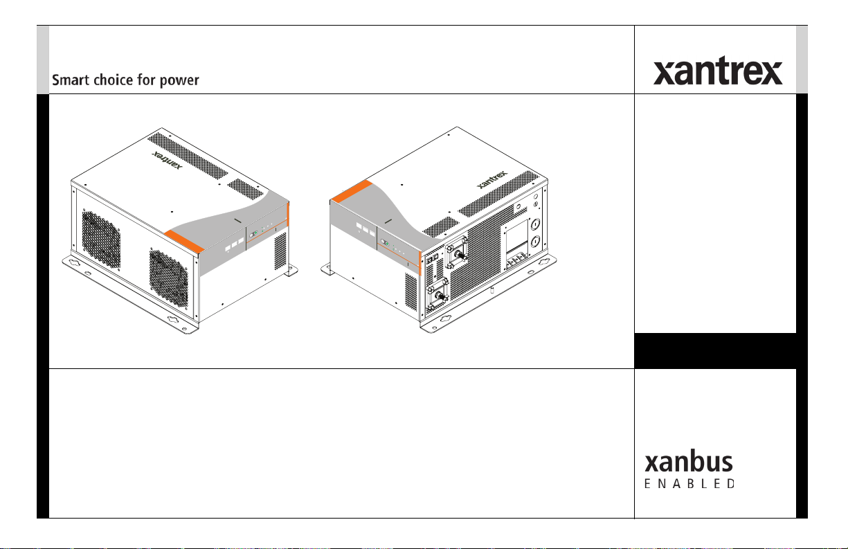
Freedom SW 3524-230 shown.
Freedom SW 230V
Sine Wave Inverter/Chargers
Installation Guide
Model Numbers
815-3524-02
815-2524-02
™
This guide for use by qualified installers only.


Copyright © 2013-2018 Schneider Electric. All Rights Reserved. All trademarks are
owned by Schneider Electric Industries SAS or its affiliated companies.
Exclusion for Documentation
UNLESS SPECIFICALLY AGREED TO IN WRITING, SELLER
(A) MAKES NO WARRANTY AS TO THE ACCURACY, SUFFICIENCY OR SUITABILITY OF ANY
TECHNICAL OR OTHER INFORMATION PROVIDED IN ITS MANUALS OR OTHER DOCUMENTATION;
B) ASSUMES NO RESPONSIBILITY OR LIABILITY FOR LOSSES, DAMAGES, COSTS OR EXPENSES,
(
WHETHER SPECIAL, DIRECT, INDIRECT, CONSEQUENTIAL OR INCIDENTAL, WHICH MIGHT ARISE
OUT OF THE USE OF SUCH INFORMATION. THE USE OF ANY SUCH INFORMATION WILL BE ENTIRELY
AT THE USER’S RISK; AND
(C) REMINDS YOU THAT IF THIS MANUAL IS IN ANY LANGUAGE OTHER THAN ENGLISH,
ALTHOUGH STEPS HAVE BEEN TAKEN TO MAINTAIN THE ACCURACY OF THE TRANSLATION, THE
ACCURACY CANNOT BE GUARANTEED. APPROVED CONTENT IS CONTAINED WITH THE ENGLISH
LANGUAGE VERSION WHICH IS POSTED AT WWW.XANTREX.COM.
Information About Your System
As soon as you open your product, record the following information and be sure to
keep your proof of purchase.
Serial Number
Product Number
Purchased From
Purchase Date
_________________________________
_________________________________
_________________________________
_________________________________
Document Part Number
975-0697-01-01
To view, download, or print the latest revision, visit the website shown under Contact
Information.
Date and Revision
Aug 2018 Rev D
Product Numbers
815-3524-02 (Freedom SW 3524-230)
815-2524-02 (Freedom SW 2524-230)
Contact Information
Telephone: +1 800 670 0707
Web: www.xantrex.com
+1 408 987 6030
975-0697-01-01 i
This guide for use by qualified installers only.

About This Guide
Purpose
The purpose of this Installation Guide is to provide explanations and
procedures for installing the Freedom SW 230V Inverter/Charger.
Scope
The Guide provides safety and installation guidelines as well as information
on tools and wiring. It does not provide details about particular brands of
batteries. You need to consult individual battery manufacturers for this
information.
Audience
The guide is intended for qualified installers and technicians of the
Freedom SW 230V Inverter/Charger.
Related Information
You can find more information about Xantrex-branded products and
services at www.xantrex.com.
ii Freedom SW 230V Installation Guide
Important Safety Instructions
IMPORTANT: READ AND SAVE THIS INSTALLATION
GUIDE FOR FUTURE REFERENCE.
This chapter contains important safety and installation instructions for the
Freedom SW 230V Inverter/Charger (Freedom SW 230V). Each time,
before using the Freedom SW 230V, READ ALL instructions and
cautionary markings on or provided with the inverter/charger, the batteries,
and all appropriate sections of this guide.
NOTE: The Freedom SW 230V contains no user-serviceable parts.
The following special messages may appear throughout this bulletin or on
the equipment to warn of potential hazards or to call attention to
information that clarifies or simplifies a procedure.
DANGER indicates an imminently hazardous situation, which, if not
avoided, will result in death or serious injury.
WARNING indicates a potentially hazardous situation, which, if not
avoided, can result in death or serious injury.
CAUTION indicates a potentially hazardous situation, which, if not
avoided, can result in moderate or minor injury.
The addition of either symbol to a “Danger” or “Warning” safety
label indicates that an electrical hazard exists which will result in
personal injury if the instructions are not followed.
This is the safety alert symbol. It is used to alert you to potential
personal injury hazards. Obey all safety messages that follow this
symbol to avoid possible injury or death.
NOTICE indicates a potentially hazardous situation, which, if not avoided,
can result in equipment damage.
IMPORTANT:
to know, however, they are not as serious as a caution or warning.
These notes describe things which are important for you
975-0697-01-01 iii
Safety Information
ELECTRICAL SHOCK HAZARD
• Do not expose the Freedom SW 230V to rain, snow, spray, or bilge
water. This inverter/charger is designed for marine applications only
when additional drip protection is installed in certain orientations.
See the installation guide for information.
• Do not operate the inverter/charger if it has received a sharp blow,
been dropped, has cracks or openings in the enclosure including if
the AC terminal cover has been lost, damaged, or will not close, or
otherwise damaged in any other way.
• Do not disassemble the inverter/charger. Internal capacitors remain
charged after all power is disconnected.
• Disconnect both AC and DC power from the inverter/charger before
attempting any maintenance or cleaning or working on any circuits
connected to the inverter/charger. The INVERTER ENABLE button
on the front panel does not function like a power switch that
energizes or de-energizes the unit arbitrarily. When AC and DC power
sources are connected and present, the unit is always energized.
• Do not operate the inverter/charger with damaged or substandard
wiring. Make sure that all wiring is in good condition and is not
undersized.
Failure to follow these instructions will result in death or serious injury.
FIRE AND BURN HAZARD
• Do not cover or obstruct the air intake vent openings and/or install in
a zero-clearance compartment.
• Do not use transformerless battery chargers in conjunction with the
inverter/charger due to overheating.
Failure to follow these instructions will result in death or serious injury.
EXPLOSION HAZARD
• Charge only properly rated (such as two 12 V in series for a 24 V
battery bank) lead-acid (GEL, AGM, Flooded, or lead-calcium)
rechargeable batteries because other battery types may explode.
• Do not work in the vicinity of lead-acid batteries. Batteries generate
explosive gases during normal operation. See note #1.
• Do not install and/or operate in compartments containing flammable
materials or in locations that require ignition-protected equipment.
See notes #2 and #3.
• When using Lithium-Ion batteries, ensure that the battery pack being
used includes a certified Battery Management System (BMS) with
safety controls.
Failure to follow these instructions will result in death or serious injury.
iv Freedom SW 230V Installation Guide
NOTES:
1. Follow these instructions and those published by the battery
manufacturer and the manufacturer of any equipment you intend to use
in the vicinity of the battery. Review cautionary markings on these
products and on the engine.
2. This inverter/charger contains components which tend to produce arcs
or sparks.
3. Locations include any space containing gasoline-powered machinery,
fuel tanks, as well as joints, fittings, or other connections between
components of the fuel system.
PHYSICAL INJURY HAZARD
This Freedom SW 230V is not intended for use by persons (including
children) with reduced physical, sensory, or mental capabilities or lack of
experience and knowledge, unless they have been given supervision or
instruction concerning use of the appliance by a person responsible for
their safety. Children should be supervised to ensure that they do not play
with the appliance.
Failure to follow these instructions can result in minor or moderate injury.
Precautions When Working With Batteries
BURN FROM HIGH SHORT-CIRCUIT CURRENT, FIRE AND
EXPLOSION FROM VENTED GASES HAZARDS
• Always wear proper, non-absorbent gloves, complete eye protection,
and clothing protection. Avoid touching your eyes and wiping your
forehead while working near batteries. See note #4.
• Remove all personal metal items, like rings, bracelets, and watches
when working with batteries. See notes #5 and #6 below.
• Never smoke or allow a spark or flame near the engine or batteries.
• Never charge a frozen battery.
• Always remove the negative terminal from the battery first for
systems with grounded negative when replacing a battery. If it is
grounded positive, remove the positive terminal first. Make sure all
loads connected to the battery and all accessories are off to avoid
causing an arc.
Failure to follow these instructions can result in death or serious injury.
NOTES:
1. Mount and place the Freedom SW 230V Inverter/Charger unit away
from batteries in a well ventilated compartment.
2. Always have someone within range of your voice or close enough to
come to your aid when you work near a lead-acid battery.
3. Always have plenty of fresh water and soap nearby in case battery acid
contacts skin, clothing, or eyes.
This guide for use by qualified installers only.
975-0697-01-01 v
4. If battery acid contacts skin or clothing, wash immediately with soap
• For flooded non-sealed batteries, add distilled water in each cell until
and water. If acid enters your eye, immediately flood it with running
cold water for at least twenty minutes and get medical attention
immediately.
5. Use extra caution to reduce the risk or dropping a metal tool on the
battery. It could spark or short circuit the battery or other electrical
parts and could cause an explosion.
Precautions When Placing the Inverter/Charger
6. Batteries can produce a short circuit current high enough to weld a ring
or metal bracelet or the like to the battery terminal, causing a severe
burn.
Precautions When Preparing to Charge
EXPOSURE TO CHEMICALS AND GASES HAZARD
• Make sure the area around the battery is well ventilated.
• Make sure the voltage of the batteries matches the output voltage of
the inverter/charger.
• Be careful to keep corrosion from coming into contact with your eyes
and skin when cleaning battery terminals.
Failure to follow these instructions can result in death or serious injury.
NOTES:
• Study and follow all of the battery manufacturer's specific precautions, such
as removing or not removing cell caps while charging, whether equalization
is acceptable for your battery, and recommended rates of charge.
battery acid reaches the level specified by the battery manufacturer.
This helps to purge excessive gas from cells. Do not overfill. For a
battery without removable cell caps, carefully follow manufacturer's
instructions.
RISK OF DAMAGE TO THE INVERTER/CHARGER
• Never allow battery acid to drip on the inverter/charger when reading
gravity, or filling battery.
• Never place the Freedom SW 230V Inverter/Charger unit directly
above batteries; gases from a battery will corrode and damage the
inverter/charger.
• Do not place a battery on top of the inverter/charger.
Failure to follow these instructions can damage the unit and/or damage
other equipment.
vi Freedom SW 230V Installation Guide

Regulatory
The Freedom SW 230V Inverter/Charger is certified to appropriate
European (CE) and Australian (RCM) standards. For more information see
“Regulatory Approvals” on page 67.
The Freedom SW 230V Inverter/Charger is intended to be used for mobile
or commercial applications. This inverter/charger is designed for marine
applications only when additional drip protection is installed in certain
orientations. Refer to this guide for installation instructions.
It is not intended for other applications as it may not comply with the
additional safety code requirements needed for those other applications. See
“Limitations On Use” below.
LIMITATIONS ON USE
Do not use in connection with life support systems or other medical
equipment or devices.
Failure to follow these instructions can result in death or serious injury.
End of Life Disposal
The Freedom SW 230V is designed with environmental awareness and
sustainability in mind. At the end of its useful life, the Freedom SW 230V
can be decommissioned and disassembled. Components which can be
recycled must be recycled and those that cannot be recycled must be
disposed of according to local, regional, or national environmental
regulations.
Many of the electrical components used in the Freedom SW 230V are made
of recyclable material like steel, copper, aluminum, and other alloys. These
materials can be auctioned off to traditional scrap metal recycling
companies who resell reusable scraps.
Electronic equipment such as the circuit boards, connectors, and fuses can
be broken down and recycled by specialized recycling companies whose
goal is to avoid having these components end up in the landfill.
For more information on disposal, contact Xantrex.
This guide for use by qualified installers only.
975-0697-01-01 vii


Contents
Important Safety Instructions
Introduction . . . . . . . . . . . . . . . . . . . . . . . . . . . . . . . . . . . . . . . . . . . . . . . . . . . . . . . . . . . . . . . . . . . . . . . . . . . . . . . . . . . . . . . . . . . . . . . . . . . .1
Materials List . . . . . . . . . . . . . . . . . . . . . . . . . . . . . . . . . . . . . . . . . . . . . . . . . . . . . . . . . . . . . . . . . . . . . . . . . . . . . . . . . . . . . . . . . . .2
Installation Information. . . . . . . . . . . . . . . . . . . . . . . . . . . . . . . . . . . . . . . . . . . . . . . . . . . . . . . . . . . . . . . . . . . . . . . . . . . . . . . . . . . . . . . . . . .3
Before You Begin the Installation . . . . . . . . . . . . . . . . . . . . . . . . . . . . . . . . . . . . . . . . . . . . . . . . . . . . . . . . . . . . . . . . . . . . . . . . . . .3
Installation Codes . . . . . . . . . . . . . . . . . . . . . . . . . . . . . . . . . . . . . . . . . . . . . . . . . . . . . . . . . . . . . . . . . . . . . . . . . . . . . . . . . . . . . . . .3
About the Xanbus System . . . . . . . . . . . . . . . . . . . . . . . . . . . . . . . . . . . . . . . . . . . . . . . . . . . . . . . . . . . . . . . . . . . . . . . . . . . . . . . . . . . . . . . . .4
Xanbus System . . . . . . . . . . . . . . . . . . . . . . . . . . . . . . . . . . . . . . . . . . . . . . . . . . . . . . . . . . . . . . . . . . . . . . . . . . . . . . . . . . . . . .4
Xanbus-enabled Products and Accessories . . . . . . . . . . . . . . . . . . . . . . . . . . . . . . . . . . . . . . . . . . . . . . . . . . . . . . . . . . . . . . . . . . . . 5
Planning the Installation . . . . . . . . . . . . . . . . . . . . . . . . . . . . . . . . . . . . . . . . . . . . . . . . . . . . . . . . . . . . . . . . . . . . . . . . . . . . . . . . . . . . . . . . . .6
Two Key Performance Factors . . . . . . . . . . . . . . . . . . . . . . . . . . . . . . . . . . . . . . . . . . . . . . . . . . . . . . . . . . . . . . . . . . . . . . . . . . . . .6
Size and Length of DC Cables . . . . . . . . . . . . . . . . . . . . . . . . . . . . . . . . . . . . . . . . . . . . . . . . . . . . . . . . . . . . . . . . . . . . . . . . . .6
Mounting Location of the Freedom SW 230V . . . . . . . . . . . . . . . . . . . . . . . . . . . . . . . . . . . . . . . . . . . . . . . . . . . . . . . . . . . . . . 6
Planning Preparations . . . . . . . . . . . . . . . . . . . . . . . . . . . . . . . . . . . . . . . . . . . . . . . . . . . . . . . . . . . . . . . . . . . . . . . . . . . . . . . . . . . . . . . . . . . . 7
AC, DC, and Network Components . . . . . . . . . . . . . . . . . . . . . . . . . . . . . . . . . . . . . . . . . . . . . . . . . . . . . . . . . . . . . . . . . . . . . . . . .7
AC Components . . . . . . . . . . . . . . . . . . . . . . . . . . . . . . . . . . . . . . . . . . . . . . . . . . . . . . . . . . . . . . . . . . . . . . . . . . . . . . . . . . . . . . . .10
AC Input . . . . . . . . . . . . . . . . . . . . . . . . . . . . . . . . . . . . . . . . . . . . . . . . . . . . . . . . . . . . . . . . . . . . . . . . . . . . . . . . . . . . . . . . . .10
AC Output . . . . . . . . . . . . . . . . . . . . . . . . . . . . . . . . . . . . . . . . . . . . . . . . . . . . . . . . . . . . . . . . . . . . . . . . . . . . . . . . . . . . . . . . .10
AC Loads . . . . . . . . . . . . . . . . . . . . . . . . . . . . . . . . . . . . . . . . . . . . . . . . . . . . . . . . . . . . . . . . . . . . . . . . . . . . . . . . . . . . . . . . . 10
AC Disconnect and Over-Current Protection Device . . . . . . . . . . . . . . . . . . . . . . . . . . . . . . . . . . . . . . . . . . . . . . . . . . . . . . . . 10
Distribution Panels . . . . . . . . . . . . . . . . . . . . . . . . . . . . . . . . . . . . . . . . . . . . . . . . . . . . . . . . . . . . . . . . . . . . . . . . . . . . . . . . . .12
AC Wiring . . . . . . . . . . . . . . . . . . . . . . . . . . . . . . . . . . . . . . . . . . . . . . . . . . . . . . . . . . . . . . . . . . . . . . . . . . . . . . . . . . . . . . . .12
DC Components . . . . . . . . . . . . . . . . . . . . . . . . . . . . . . . . . . . . . . . . . . . . . . . . . . . . . . . . . . . . . . . . . . . . . . . . . . . . . . . . . . . . . . . .13
. . . . . . . . . . . . . . . . . . . . . . . . . . . . . . . . . . . . . . . . . . . . . . . . . . . . . . . . . . . . . . . . . . . . . . . . . . . . . . . . . . . . iii
This guide for use by qualified installers only.

Batteries . . . . . . . . . . . . . . . . . . . . . . . . . . . . . . . . . . . . . . . . . . . . . . . . . . . . . . . . . . . . . . . . . . . . . . . . . . . . . . . . . . . . . . . . . .13
DC Cabling . . . . . . . . . . . . . . . . . . . . . . . . . . . . . . . . . . . . . . . . . . . . . . . . . . . . . . . . . . . . . . . . . . . . . . . . . . . . . . . . . . . . . . . .14
DC Disconnects and Over-Current Devices . . . . . . . . . . . . . . . . . . . . . . . . . . . . . . . . . . . . . . . . . . . . . . . . . . . . . . . . . . . . . . . 14
DC Grounding . . . . . . . . . . . . . . . . . . . . . . . . . . . . . . . . . . . . . . . . . . . . . . . . . . . . . . . . . . . . . . . . . . . . . . . . . . . . . . . . . . . . .15
Unpacking and Inspecting the Freedom SW 230V Inverter/Charger . . . . . . . . . . . . . . . . . . . . . . . . . . . . . . . . . . . . . . . . . . . . . . .16
Installation Tools and Materials . . . . . . . . . . . . . . . . . . . . . . . . . . . . . . . . . . . . . . . . . . . . . . . . . . . . . . . . . . . . . . . . . . . . . . . . . . . .17
Tools . . . . . . . . . . . . . . . . . . . . . . . . . . . . . . . . . . . . . . . . . . . . . . . . . . . . . . . . . . . . . . . . . . . . . . . . . . . . . . . . . . . . . . . . . . . . .17
Materials . . . . . . . . . . . . . . . . . . . . . . . . . . . . . . . . . . . . . . . . . . . . . . . . . . . . . . . . . . . . . . . . . . . . . . . . . . . . . . . . . . . . . . . . . .17
Installing the Inverter/Charger . . . . . . . . . . . . . . . . . . . . . . . . . . . . . . . . . . . . . . . . . . . . . . . . . . . . . . . . . . . . . . . . . . . . . . . . . . . . . . . . . . . .18
Overview . . . . . . . . . . . . . . . . . . . . . . . . . . . . . . . . . . . . . . . . . . . . . . . . . . . . . . . . . . . . . . . . . . . . . . . . . . . . . . . . . . . . . . . . . . . . .18
Step 1: Choosing a Location for the Inverter/Charger . . . . . . . . . . . . . . . . . . . . . . . . . . . . . . . . . . . . . . . . . . . . . . . . . . . . . . . . . . .19
Step 2: Mounting the Inverter/Charger . . . . . . . . . . . . . . . . . . . . . . . . . . . . . . . . . . . . . . . . . . . . . . . . . . . . . . . . . . . . . . . . . . . . . . 21
Considerations . . . . . . . . . . . . . . . . . . . . . . . . . . . . . . . . . . . . . . . . . . . . . . . . . . . . . . . . . . . . . . . . . . . . . . . . . . . . . . . . . . . . .21
Step 3: Connecting the AC Input and AC Output Wires . . . . . . . . . . . . . . . . . . . . . . . . . . . . . . . . . . . . . . . . . . . . . . . . . . . . . . . . . 25
General AC Wiring Considerations . . . . . . . . . . . . . . . . . . . . . . . . . . . . . . . . . . . . . . . . . . . . . . . . . . . . . . . . . . . . . . . . . . . . .25
Connecting AC Input Wires . . . . . . . . . . . . . . . . . . . . . . . . . . . . . . . . . . . . . . . . . . . . . . . . . . . . . . . . . . . . . . . . . . . . . . . . . . .26
Connecting the AC Output Wires . . . . . . . . . . . . . . . . . . . . . . . . . . . . . . . . . . . . . . . . . . . . . . . . . . . . . . . . . . . . . . . . . . . . . . .27
Step 4: Connecting the DC Cables . . . . . . . . . . . . . . . . . . . . . . . . . . . . . . . . . . . . . . . . . . . . . . . . . . . . . . . . . . . . . . . . . . . . . . . . . .29
DC Connection Precautions . . . . . . . . . . . . . . . . . . . . . . . . . . . . . . . . . . . . . . . . . . . . . . . . . . . . . . . . . . . . . . . . . . . . . . . . . . .29
Recommended Cable Sizes and Lengths and Fuse Size . . . . . . . . . . . . . . . . . . . . . . . . . . . . . . . . . . . . . . . . . . . . . . . . . . . . . .29
Preparing the Cables . . . . . . . . . . . . . . . . . . . . . . . . . . . . . . . . . . . . . . . . . . . . . . . . . . . . . . . . . . . . . . . . . . . . . . . . . . . . . . . . . 29
Guidelines for Routing the DC Cables . . . . . . . . . . . . . . . . . . . . . . . . . . . . . . . . . . . . . . . . . . . . . . . . . . . . . . . . . . . . . . . . . . .30
Connecting the DC Cables to the Inverter/Charger . . . . . . . . . . . . . . . . . . . . . . . . . . . . . . . . . . . . . . . . . . . . . . . . . . . . . . . . .31
DC Grounding . . . . . . . . . . . . . . . . . . . . . . . . . . . . . . . . . . . . . . . . . . . . . . . . . . . . . . . . . . . . . . . . . . . . . . . . . . . . . . . . . . . . .33
Step 5: Connecting the Battery Temperature Sensor (BTS) . . . . . . . . . . . . . . . . . . . . . . . . . . . . . . . . . . . . . . . . . . . . . . . . . . . . . .35
Mounting Options . . . . . . . . . . . . . . . . . . . . . . . . . . . . . . . . . . . . . . . . . . . . . . . . . . . . . . . . . . . . . . . . . . . . . . . . . . . . . . . . . . .35
Mounting to the Negative Battery Terminal . . . . . . . . . . . . . . . . . . . . . . . . . . . . . . . . . . . . . . . . . . . . . . . . . . . . . . . . . . . . . . .36

Mounting to the Side of the Battery Case . . . . . . . . . . . . . . . . . . . . . . . . . . . . . . . . . . . . . . . . . . . . . . . . . . . . . . . . . . . . . . . . .38
Step 6: Connecting to the Network . . . . . . . . . . . . . . . . . . . . . . . . . . . . . . . . . . . . . . . . . . . . . . . . . . . . . . . . . . . . . . . . . . . . . . . . .39
Step 7: Performing Checks Prior to Initial Start-Up . . . . . . . . . . . . . . . . . . . . . . . . . . . . . . . . . . . . . . . . . . . . . . . . . . . . . . . . . . . .40
Step 8: Testing Your Installation . . . . . . . . . . . . . . . . . . . . . . . . . . . . . . . . . . . . . . . . . . . . . . . . . . . . . . . . . . . . . . . . . . . . . . . . . . .41
Testing in Invert Mode . . . . . . . . . . . . . . . . . . . . . . . . . . . . . . . . . . . . . . . . . . . . . . . . . . . . . . . . . . . . . . . . . . . . . . . . . . . . . . .41
Testing in Charge Mode and AC Bypass Mode . . . . . . . . . . . . . . . . . . . . . . . . . . . . . . . . . . . . . . . . . . . . . . . . . . . . . . . . . . . .42
Installation Complete . . . . . . . . . . . . . . . . . . . . . . . . . . . . . . . . . . . . . . . . . . . . . . . . . . . . . . . . . . . . . . . . . . . . . . . . . . . . . . . .43
Stacking Features . . . . . . . . . . . . . . . . . . . . . . . . . . . . . . . . . . . . . . . . . . . . . . . . . . . . . . . . . . . . . . . . . . . . . . . . . . . . . . . . . . . . . . . . . . . . . .44
Parallel Stacking . . . . . . . . . . . . . . . . . . . . . . . . . . . . . . . . . . . . . . . . . . . . . . . . . . . . . . . . . . . . . . . . . . . . . . . . . . . . . . . . . . . . . . .45
DC Connections for Stacked Inverters . . . . . . . . . . . . . . . . . . . . . . . . . . . . . . . . . . . . . . . . . . . . . . . . . . . . . . . . . . . . . . . . . . . . . .46
Neutral Wiring for Stacked Inverters . . . . . . . . . . . . . . . . . . . . . . . . . . . . . . . . . . . . . . . . . . . . . . . . . . . . . . . . . . . . . . . . . . . . . . . . 47
Configuring System for Stacked Operation . . . . . . . . . . . . . . . . . . . . . . . . . . . . . . . . . . . . . . . . . . . . . . . . . . . . . . . . . . . . . . . . . . .48
Search Mode Operation in Parallel Stacking . . . . . . . . . . . . . . . . . . . . . . . . . . . . . . . . . . . . . . . . . . . . . . . . . . . . . . . . . . . . . . . . . .49
Disabling Search Mode on the Master Unit . . . . . . . . . . . . . . . . . . . . . . . . . . . . . . . . . . . . . . . . . . . . . . . . . . . . . . . . . . . . . . .49
Setting Search Mode on the Slave Unit . . . . . . . . . . . . . . . . . . . . . . . . . . . . . . . . . . . . . . . . . . . . . . . . . . . . . . . . . . . . . . . . . .49
Wiring Schematic . . . . . . . . . . . . . . . . . . . . . . . . . . . . . . . . . . . . . . . . . . . . . . . . . . . . . . . . . . . . . . . . . . . . . . . . . . . . . . . . . . . . . . .50
Charger Settings in a Dual Freedom SW Configuration . . . . . . . . . . . . . . . . . . . . . . . . . . . . . . . . . . . . . . . . . . . . . . . . . . . . . . . .51
Calculations . . . . . . . . . . . . . . . . . . . . . . . . . . . . . . . . . . . . . . . . . . . . . . . . . . . . . . . . . . . . . . . . . . . . . . . . . . . . . . . . . . . . . . .51
Examples . . . . . . . . . . . . . . . . . . . . . . . . . . . . . . . . . . . . . . . . . . . . . . . . . . . . . . . . . . . . . . . . . . . . . . . . . . . . . . . . . . . . . . . . . .53
Inverter/Charger Physical Specifications . . . . . . . . . . . . . . . . . . . . . . . . . . . . . . . . . . . . . . . . . . . . . . . . . . . . . . . . . . . . . . . . . . . . . . . . . . . .56
Battery Information . . . . . . . . . . . . . . . . . . . . . . . . . . . . . . . . . . . . . . . . . . . . . . . . . . . . . . . . . . . . . . . . . . . . . . . . . . . . . . . . . . . . . . . . . . . . .57
Battery Bank Sizing . . . . . . . . . . . . . . . . . . . . . . . . . . . . . . . . . . . . . . . . . . . . . . . . . . . . . . . . . . . . . . . . . . . . . . . . . . . . . . . . . . . . .57
Estimating Battery Requirements . . . . . . . . . . . . . . . . . . . . . . . . . . . . . . . . . . . . . . . . . . . . . . . . . . . . . . . . . . . . . . . . . . . . . . . . . .58
Calculating Battery Size . . . . . . . . . . . . . . . . . . . . . . . . . . . . . . . . . . . . . . . . . . . . . . . . . . . . . . . . . . . . . . . . . . . . . . . . . . . . . .58
Battery Banks . . . . . . . . . . . . . . . . . . . . . . . . . . . . . . . . . . . . . . . . . . . . . . . . . . . . . . . . . . . . . . . . . . . . . . . . . . . . . . . . . . . . . .60
Battery Bank Sizing Worksheet . . . . . . . . . . . . . . . . . . . . . . . . . . . . . . . . . . . . . . . . . . . . . . . . . . . . . . . . . . . . . . . . . . . . . . . .60
Restrictions on Motor Size . . . . . . . . . . . . . . . . . . . . . . . . . . . . . . . . . . . . . . . . . . . . . . . . . . . . . . . . . . . . . . . . . . . . . . . . . . . . . . . .60
This guide for use by qualified installers only.

Battery Cabling and Hook-up Configurations. . . . . . . . . . . . . . . . . . . . . . . . . . . . . . . . . . . . . . . . . . . . . . . . . . . . . . . . . . . . . . . . . . . . . . . . .62
Battery Series Connection . . . . . . . . . . . . . . . . . . . . . . . . . . . . . . . . . . . . . . . . . . . . . . . . . . . . . . . . . . . . . . . . . . . . . . . . . . . .62
Battery Series-Parallel Connections . . . . . . . . . . . . . . . . . . . . . . . . . . . . . . . . . . . . . . . . . . . . . . . . . . . . . . . . . . . . . . . . . . . . .63
Specifications . . . . . . . . . . . . . . . . . . . . . . . . . . . . . . . . . . . . . . . . . . . . . . . . . . . . . . . . . . . . . . . . . . . . . . . . . . . . . . . . . . . . . . . . . . . . . . . . .64
Inverter Drip Shield Installation . . . . . . . . . . . . . . . . . . . . . . . . . . . . . . . . . . . . . . . . . . . . . . . . . . . . . . . . . . . . . . . . . . . . . . . . . . . . . . . . . . .68

Introduction
The Installation Guide provides detailed information for
installing the Freedom SW 230V Inverter/Charger and the
battery temperature sensor, wiring the inverter/charger to the
AC and DC circuits, and connecting the inverter/charger to
the Xanbus system.
The Freedom SW 230V is a Xanbus-enabled device that
typically powers the Xanbus system.
This Installation Guide provides:
• safety instructions that must be observed during
installation.
• a typical Xanbus system diagram (if applicable).
• information on additional required AC and DC
components.
• a list of installation tools and materials.
• detailed procedures for a typical installation.
This guide for use by qualified installers only.
975-0697-01-01 1
Introduction
Materials List
The Freedom SW 230V ships with the following items:
• one Freedom SW 230V unit
• owner’s and installation guides
• Battery Temperature Sensor (BTS)
• DC terminal covers (one red, one black) with
two sets of #6-32 screws
• two Xanbus network terminators
• two sets of 5/16”-18 nuts and washers for the DC
terminals
3524
INVERTER
ENABLE
RESET
CLEAR FAULT
FREEDOM SW
FREEDOM
Freedom SW 3524-230
INVERTER
ENABLED
GEN
SUPPORT
AC IN FAULT
INGWARNING
CHARG
SW
3524
shown
Installation and
Owner’s Guides
NOTE: If any of the items are missing, contact customer
service or any authorized Xantrex dealer for replacement. See
Xanbus network
terminators
BTS
“Contact Information” on page i.
IMPORTANT: Keep the carton and packing material in case you need to
return the Freedom SW 230V for servicing.
2 Freedom SW 230V Installation Guide
nuts and washers
Figure 1 Materials List
DC terminal covers
with screws

Installation Information
Before You Begin the Installation
Before beginning your installation:
• Read the entire Installation Guide so you can plan the
installation from beginning to end.
• Assemble all the tools and materials you require for the
installation.
• Review the Important Safety Instructions on page iii.
• Be aware of all safety and electrical codes which must be
met.
ELECTRICAL SHOCK AND FIRE HAZARDS
• All wiring should be done by qualified personnel to ensure
compliance with all applicable installation codes and regulations.
• Disconnect all AC and DC power sources.
• Disable and secure all AC and DC disconnect devices and automatic
generator starting devices.
Failure to follow these instructions will result in death or serious injury.
Installation Codes
Applicable installation codes vary depending on the specific
location and application of the installation.
This guide for use by qualified installers only.
975-0697-01-01 3
About the Xanbus System
Xanbus System
The Xanbus system includes the Freedom SW 230V and
other Xanbus-enabled devices. The Freedom SW 230V is the
device in a Xanbus system that typically provides network
power—500 mA at 12 volts DC. All of the Xanbus-enabled
devices, such as the Freedom SW 230V, the SCP, and the
AGS are able to communicate their settings and activity to
each other.
The Xanbus-enabled designation (see below) means that this
product works on a Xanbus network. Xanbus-enabled
products are:
• Simple to operate and routine tasks are automated.
• Controlled by software that eliminates analog signalling
errors.
• Less susceptible to interference and line loss.
• Upgradable through new software releases.
Shore
Power
System Control Panel
Xanbus System Control Panel
network terminator network terminator
Automatic Generator Start
Xanbus Automatic Generator Start
Generator
Figure 2 Typical Xanbus System Diagram
4 Freedom SW 230V Installation Guide
AC Panel
AC Loads
Freedom SW Inverter/Charger
BATTERY
3524
Fault
C/
ge
r
er A
t
ha
r
C
e
nv
I
On
er
t
SW
r
e
v
n
I
3524
set Enable
e
R
SW
FREEDOM
FREEDOM
For detailed instructions and a complete list of Xanbus-
Inverter
Load Panel
enabled devices, visit www.xantrex.com
Xanbus-enabled Products and Accessories
About the Xanbus System
SCP
AGS
Xanbus-enabled Products (Shown above)
25-ft cable 75-ft cable3-ft cable
Inverter drip shield
Product Number/s
Xanbus System Control Panel (SCP) 809-0921
Xanbus Automatic Generator Start (AGS) 809-0915
3-ft network cable (0.9 m) 809-0935
25-ft network cable (7.6 m) 809-0940
75-ft network cable (22.9 m) 809-0942
Accessories (Shown above)
Product Number/s
Freedom SW On/Off Switch (Not shown) 808-9002
Inverter drip shield 808-9004
975-0697-01-01 5
This guide for use by qualified installers only.

Planning the Installation
This section provides information to help you plan for a basic
installation of the Freedom SW 230V.
As your system configuration is determined, record the details
in “Information About Your System” in the Freedom SW
230V Sine Wave Inverter/Charger Owner’s Guide.
Two Key Performance Factors
Two key factors in particular will have a major impact on
system performance.
Size and Length of DC Cables
To select the appropriate size and length of DC cables, see
“DC Cabling” on page 14.
The DC cables should be as short as possible and large
enough to handle the required current, in accordance with the
electrical codes or regulations applicable to your installation.
If there are long battery cables which are in excess of 3 meters
each and not of sufficient size, the voltage drop across the
cables will have a negative impact on overall system
performance.
Mounting Location of the Freedom SW 230V
To choose an appropriate location for mounting the inverter/
charger, see “Step 1: Choosing a Location for the Inverter/
Charger” on page 19.
6 Freedom SW 230V Installation Guide

Planning Preparations
AC, DC, and Network Components
For a successful installation, you need to plan for AC, DC,
and network components of the power system. The AC and
DC components are described in this section and illustrated in
Figure 3 on page 8.
AC components include:
• AC Input
• AC Loads
• AC Disconnect and Over-Current Protection Device
• Distribution Panels
• AC Wiring
DC components include:
• 24-volt Batteries
• DC Cabling
• DC Cabling
• DC Grounding
975-0697-01-01 7
Network considerations for Freedom SW only include:
• Cables, connectors, network connectors, and terminators
for the SCP and Automatic Generator Start, if installing.
Detailed information on planning and installing your
network is available in the Xanbus System Installation
Guide. Refer to the system guide to determine the type of
network layout to install, as well as guidelines for
installing the network. This guide is available for
download at www.xantrex.com
This guide for use by qualified installers only.
Planning Preparations
Sine Wave
Inverter/Charger
FREEDOM SW
3524
R
eset Enable
I
n
v
e
r
t
er
System Control Panel (SCP) Automatic Generator Start (AGS)
DC –
DC +
House
Battery
BTS
Inverter
AC Panel
I
n
ve
r
On
t
er
AC/
C
ha
r
ge
Fault
FREEDOM
SW
3524
Generator
AC Out
AC Main
Panel
Transfer Switch
AC In
Isolator
Non-Inverter Lo ads
Utility Power
Alternator
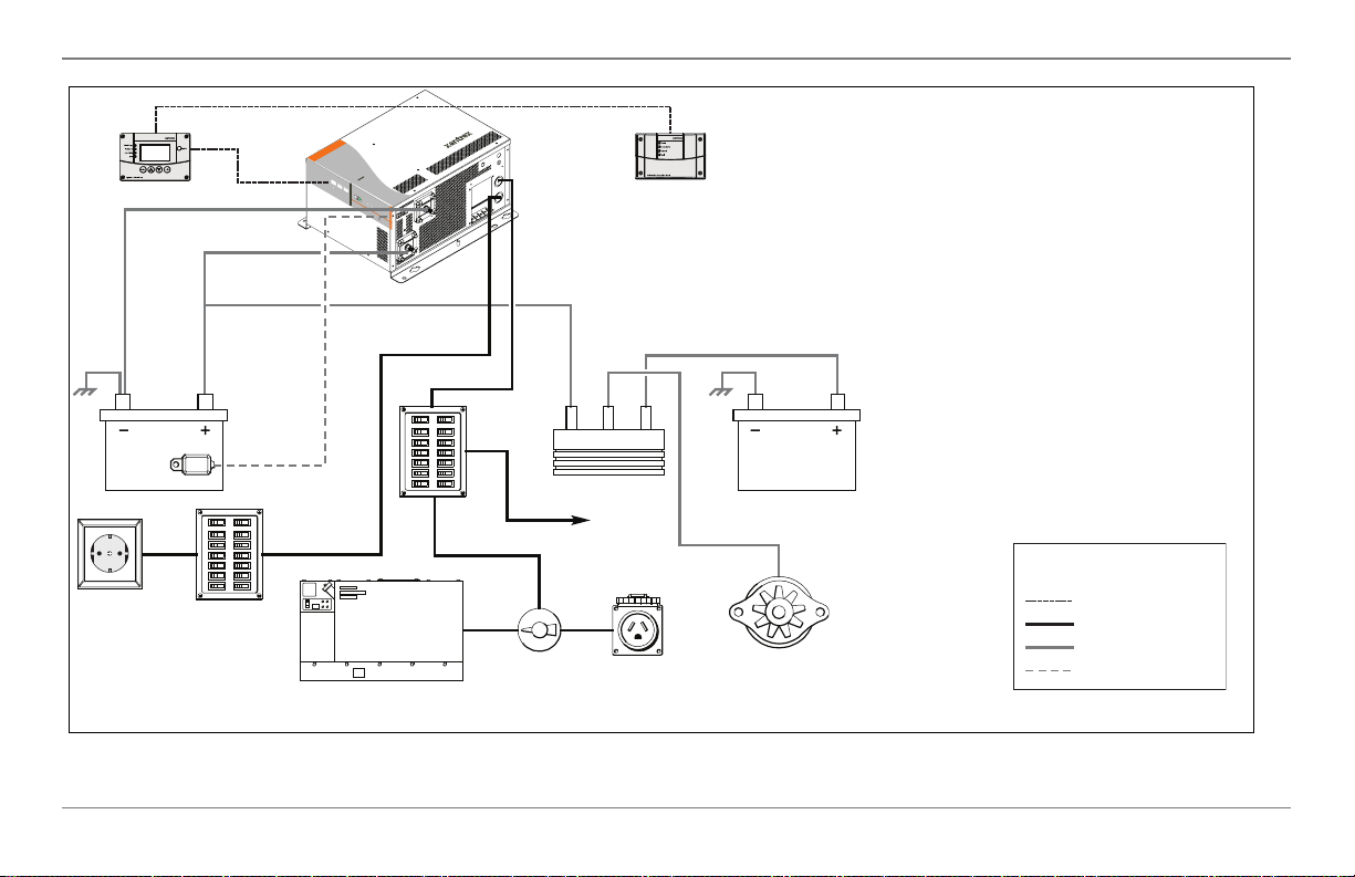
IMPORTANT: Figure 3 does not show all
required grounding or overcurrent
protection. See the next two pages as well
as on page 14 for required DC grounding or
overcurrent protection.
Always hire a qualified installer or you must
be the one to ensure that all electrical safety
requirements are met before, during, and
after installation.
Engine Battery
Legend:
Xanbus Network
AC
DC
Low Voltage DC
Figure 3 Typical Recreational Vehicle Electrical System
8 Freedom SW 230V Installation Guide
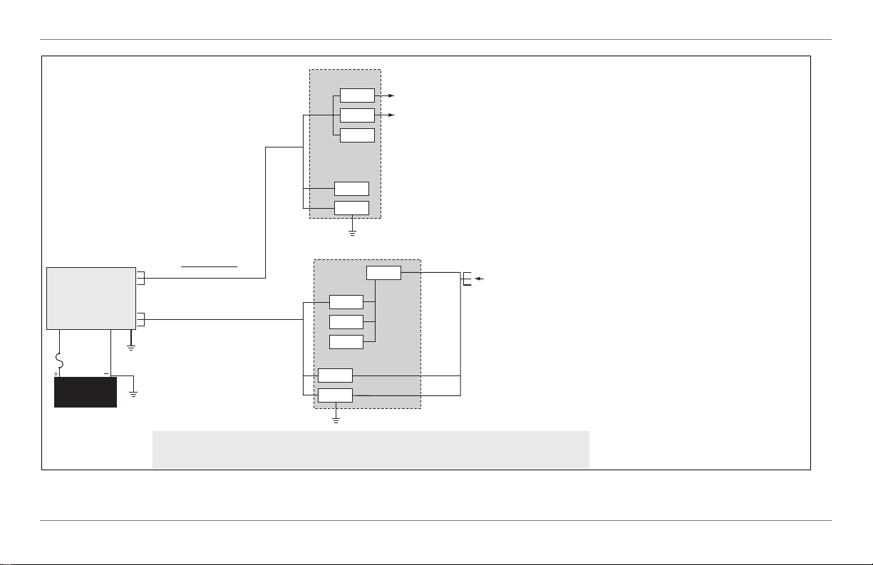
Planning Preparations
See “DC Cabling” on
page 14 and “DC
Disconnects and OverCurrent Devices” on
page 14 for cable sizes
and fuse ratings.
230 V AC OUT
2524 and 3524
Inverter/Charger
230 V AC IN
Battery (Bank)
24 V
NOTE: The DC grounding conductor may be one size smaller than the minimum size conductor required for the DC current carrying conductors providing the overcurrent protection device in the DC
positive conductor is rated no greater than 135% of the ampacity of the DC grounding conductor and the conductor is no smaller than 2mm2.
HARDWIRE CONNECTIONS
30 A MAX in pass-through
HOT = BROWN, BLACK, OR GREY
NEUTRAL = BLUE
GND = GREEN WITH YELLOW STRIPE
INVERTER AC SUB PANEL (TYPICAL)
15 A
20 A
Neutral
GND
MAIN ELECTRICAL PANEL
MAIN
30 A
Neutral
GND
HOT BUS
TO AC APPLIANCE
LOADS
IMPORTANT: Read Owner’s and Installation
Guides prior to installation. Always refer to local and
national electrical codes for proper wire and breaker
sizes prior to installation.
FROM SHORE OR
GENERATOR POWER
This guide for use by qualified installers only.
Figure 4 Wiring and Breakers Block Diagram for Freedom SW 230V 2524 / 3524
975-0697-01-01 9

Planning Preparations
AC Components
NOTE: Unless otherwise referenced specifically by product
name, the components refer to all models of Freedom SW
inverter/chargers.
AC Input
AC input can be supplied from a single-phase 230-volt 50-Hz
AC source such as the utility grid (power company), a
generator, or the output of a transfer switch.
AC Output
The output voltage on Freedom SW inverter/chargers is
230 volts AC. The Freedom SW 2524-230 and Freedom SW
3524-230 models have a Single Input and Single Output line
(SI-SO) configuration.
AC Loads
The Freedom SW 230V is intended to power loads consisting
of 230 volts/50 Hz AC appliances.
In Invert mode, the Freedom SW 230V provides 230 volts/
50 Hz AC to loads connected to Line out. In AC Bypass
mode, the source connected to the AC input is passed through
to the load. Only 230 volts/50 Hz AC appliances can be
connected to the Freedom SW 230V output.
AC Disconnect and Over-Current Protection
Device
To meet mobile electrical code requirements, and to protect
system wiring, the AC inputs and outputs of the inverter/
charger must be provided with overcurrent protection on both
the AC input and output. This protection may be a circuit
breaker or a fuse with a disconnect device (for simplicity the
following refers to breakers). Refer to your applicable
installation codes and the following requirements:
10 Freedom SW 230V Installation Guide

AC Input Protection
Planning Preparations
GFCI Requirements
The breaker protecting the AC input of the Freedom SW
230V must be approved for use on 230 volts AC branch
circuit. The breaker must be rated no more than 30 amps
maximum.
AC Output Protection
The breaker between the Freedom SW 230V AC output and
the AC loads must be rated to protect the AC output wire size
used. If the AC output wiring is based on the full 30-amp
pass-through rating, then a 30-amp output breaker is
acceptable. If the AC output wiring is smaller, then the
breaker size will have to be smaller as well, in accordance
with applicable electrical installation codes.
A GFCI (ground fault circuit interrupter) is a device that deenergizes a circuit when a current to ground exceeds a
specified value that is less than that required to open the
circuit breaker. GFCIs are intended to protect people from
electric shocks and are usually required in wet or damp
locations.
Installation in recreational vehicles may require GFCI
protection of certain branch circuits. Consult all applicable
codes.
Disconnect Devices
Each system requires a method of disconnecting the AC
circuits. If the overcurrent protection device is a circuit
breaker, it will also serve as the disconnect. If fuses are used,
separate AC disconnect switches will be needed between the
source and the fuses.
This guide for use by qualified installers only.
975-0697-01-01 11

Planning Preparations
Distribution Panels
Some systems incorporate distribution panels both ahead of
the inverter/charger (the AC source panel) and between the
inverter/charger and the loads (the AC load panel). The AC
source panel includes a main circuit breaker, which serves as
overcurrent protection for the panel. Additional circuit
breakers serve individual circuits, one of which serves the
inverter/charger.
AC Wiring
Definition AC wiring includes input wiring (all the wires
and connectors between the AC source and the inverter/
charger input) and output wiring (all the wires between the
inverter/charger and the AC load panels, circuit breakers, and
loads).
Type The type of wiring required varies according to the
electrical codes or regulations applicable to your installation.
For RV applications, this may be solid wire in multiconductor cables, but stranded wire is required if single
conductors are used. All wiring must be rated 75 °C or higher.
Size of AC Input Wiring Wire size must be coordinated
with the overcurrent protection provided ahead of the wire
involved, in accordance with the electrical codes or
regulations applicable to your installation. Therefore, the
wiring used between the AC input circuit breaker and the
inverter/charger input must be sized to match the input
breaker rating.
12 Freedom SW 230V Installation Guide
 Loading...