

Page 1
Xantrex CR Series
e
Backup System
Inverter ⁄ Charger
CR 1012E CR1012
CR 1024E CR1024
CR 1512E CR1512
CR 1524E CR1524
CR 2412E CR2412
CR 2424E CR2424
User Guide
Manu al Typ
Page 2

Page 3

Contents
Important Safety In str uctions
1
Introduction
CR Series Function and Operation - - - - - - - - - - - - - - - - - - - - - 7
Features - - - - - - - - - - - - - - - - - - - - - - - - - - - - - - - - - - - - - - - 9
AC End- - - - - - - - - - - - - - - - - - - - - - - - - - - - - - - - - - - - 10
DC End- - - - - - - - - - - - - - - - - - - - - - - - - - - - - - - - - - - - 10
2
Installation
CR Series Mounting - - - - - - - - - - - - - - - - - - - - - - - - - - - - - - 11
Mounting on Wallboard- - - - - - - - - - - - - - - - - - - - - - - - - 11
Mounting on Other Types of Walls - - - - - - - - - - - - - - - - - 14
Battery Cable Connection - - - - - - - - - - - - - - - - - - - - - - - - - - 14
DC Disconnect and Over-Current Protection - - - - - - - - - - - - - 17
AC Connections- - - - - - - - - - - - - - - - - - - - - - - - - - - - - - - - - 18
3
Operation
Front Panel Controls and LED Indicators - - - - - - - - - - - - - - - - 21
Power On/Off - - - - - - - - - - - - - - - - - - - - - - - - - - - - - - - 21
AC Mode LED- - - - - - - - - - - - - - - - - - - - - - - - - - - - - - - 21
Battery Mode LED - - - - - - - - - - - - - - - - - - - - - - - - - - - - 22
Charger LED - - - - - - - - - - - - - - - - - - - - - - - - - - - - - - - - 22
Failed (Fault) LED - - - - - - - - - - - - - - - - - - - - - - - - - - - - 22
Battery Bank Capacity- - - - - - - - - - - - - - - - - - - - - - - - - - 22
Audible Alarm (internal) - - - - - - - - - - - - - - - - - - - - - - - - 22
Circuit Breakers - - - - - - - - - - - - - - - - - - - - - - - - - - - - - - 23
RS232 Communications - - - - - - - - - - - - - - - - - - - - - - - - 23
- - - - - - - - - - - - - - - - - - - -iii
A
Specifications
- - - - - - - - - - - - - - - - - - - - - - - - - - - - - - 25
Warran ty I nfo rma tion
- - - - - - - - - - - - - - - - - - - - - - - - - - 29
i
Page 4

About Xantrex
Xantrex Technology Inc. is a world-leading supplier of advanced power electronics
and controls with products from 50 watt mobile units to one MW utility-scale
systems for wind, solar, batte r ies, fuel cells, microturbines, and backup power
applications in both grid-connected and stand-alone systems. Xantrex products
include inverters, battery chargers, programmable power s upplies, and variable
speed drives that convert, supply, control, clean, and dist ribute electric al power.
T rademarks
Xantrex CR Series Bac kup S ystem Inverter ⁄ Charger is a trademark of Xantrex
Intern ational. Xantrex is a registered trademark of Xantrex International.
Other trademar ks, r egistere d trad emark s, and pro duc t names ar e t he prope rty of t heir
respective owners and are used herein for identification purposes only.
Notice of Copyright
Xantrex CR Se ries Backup Syste m Inve rter ⁄ Charger User Guide © September 2005
Xantrex International. All rights reserve d.
Disclaimer
UNLESS SPECIFICALLY AGREED TO IN WRITING, XANTREX TECHNOLOGY INC.
(“XANTREX”)
(a) MAKES NO WARRANTY AS TO THE ACCURACY, SUFFICIENCY OR SUITABILITY OF
ANY TECHNICAL OR OTHER INFORMATION PROVIDED IN ITS MANUALS OR OTHER
DOCUMENTATION.
(b) ASSUMES NO RESPONSIBILITY OR LIABILITY FOR LOSS OR DAMAGE, WHETHER
DIRECT, INDIRECT, CONSEQUENTIAL OR INCIDENTAL, WHICH MIGHT ARISE OUT OF THE
USE OF SUCH INFORMATION. THE USE OF ANY SUCH INFORMATION WILL BE ENTIRELY
AT THE USER’S RISK.
Date and Revision
September 2005 Revision B
Part Number
975-0252-01-01
Contact Inform a tion
Telephone: +34 93 470 5330 (Europe)
1 360 925 5097 (Direct North America and rest of world)
Fax: +34 93 473 6093 (Europe)
1 360 925 5143 (Direct North America and rest of world)
Email: support.eur ope@xantrex.com (Europe)
customerservice@xantrex.com (North America and rest of world)
Web: www.xantrex.com
ii 975-0252-01-01
Page 5
Important Safety Instructions
WARNING
This chapter conta ins important safety and operating instructions.
Read and keep this User Guide for future referenc e.
READ AND SAVE THESE INSTRUCTIONS
Before using the Xantrex CR Series Backup System
Inverter ⁄ Charger (CR Series), read and obey all instructio ns
and cautionary markings on the CR Series, the batteries, and
in all sections of this inst ruction manual.
WARNING
The following warnings identify conditions or practices that could
lead to injury or loss of life
1. To reduce risk of fire and electric shock, Xantrex
recommends that all wiring be done by a qualified
electricia n to ensu re adh er en ce t o the local and national
electrical code s applicable in your application.
2. To reduce risk of injury and damage, charge only deepcycle lead acid type rechargeable batteries. Other types of
batteries may burst, causing personal injury and damage.
3. To reduce risk of shock or fire, do not disassemble the
CR Series. It contains no user-serviceable parts and
internal capacitors remain charged after all power is
disconnected. Take it to a qualified service center when
service or repair is required. Incorrect re-assembly may
result in risk of shock or fire.
4. To reduce risk of electric shock, disconnect all AC and
DC sources before attempting any maintenance or
cleaning. Turning off the CR Series will not reduce this
risk.
iii
Page 6

Safety
5. To reduce risk of fire and electric shock, make sure that
existing wiring is in good condition and that wire is not
undersized. Do not operate the CR Series with damaged
or substandard wiring.
6. EXPLOSION HAZARD WORKING IN VICINITY OF
A LEAD ACID BATTER Y IS DANGEROUS.
BATTERIES GENERATE EXPLOSIVE GASES
DURING NORMAL OPERATION. Provide ventilation
to outdoors from the battery compartment. The battery
enclosure should be desig ned to prev ent accumulation
and concentratio n of hydrogen gas in "poc kets" at the top
of the compartment. Vent the battery compartment from
the highest point. A sloped lid can also be used to direct
the flow to the vent opening location. Follow the
instructions in this manual and those of the battery
manufacturer regarding charging and ventilation.
7. EXPLOSION HAZARD: This equipment contains
components which tend to produce arcs or can spark. To
prevent fire or explosi on, do not install the CR Series in
compartments containing batteries or flammable
materials or in locations that require ignition-protected
equipment. This includes any space containing gasolinepowered machiner y, fuel tanks, or joints , fi tting s, or other
connectio ns bet ween compone nts of the fuel sys tem.
8. Do not operate the inverter/charger if it has received a
sharp blow, been dropped, or otherwise damaged in any
way . If the unit is damage d, see the Warranty information
elsewhere in this manual.
9. To reduce risk of shock hazard and damage, do not
expose the CR Series to r ain, snow or li quids of a ny type.
The CR Series is designed for indoor mounting only.
Protect the CR Series from splashing if used in vehicle
applications.
10. The inverter/charger must be properly grounded and
provided with AC and DC disconnects and overcurr ent
protection as speci fied in this manual and in accordance
with appli cable electrical codes.
iv
Page 7

Safety
11. Be extra cautious when working with metal tools on, or
around batteries . The pot ential exists to drop a tool and
short-circuit the batteries or other electrical parts
resulting in sparks that could cause an explosion.
WARNING
Obey the following pe rsonal precautions while working with and
charging batteries. These warnings concern condit ions or practices
that could lead to injury or loss of life.
1. Someone should be within range of your voice to come to
your aid when you work near batteries.
2. Have plenty of fresh water and soap nearby in case
battery acid contacts skin, clothing, or e yes.
3. Wear complete eye protection and clothing protection.
Avoid touching eyes while working near batteries. Wash
your hands when done.
4. If battery acid contacts skin or clothing, wash
immediat ely with so ap and wat er. If acid enters ey es,
immediately flood eyes wit h running cool water for at
least 15 minutes and get medical attention immediately.
Baking soda neutralize s lead acid ba ttery electrolyte.
Keep a supply on hand in the area of the batteries
5. NEVER smoke or allow a spark or flame in vicinity of a
battery or generator.
6. Be extra cautious when working with metal tools on, and
around batteries . Pot ential exists to short-circuit the
batteries or other electrical parts which may result in a
spark which could cause an explosion.
7. Remove personal metal items such as rings, bracelets,
necklaces, and wa tches when working with a battery. A
battery can pr oduce a s hort-ci rcuit c urrent high enough t o
weld a ring, or the like, to metal causi ng severe burns.
v
Page 8

Safety
CAUTION
The following cautions identify cond itions or practice s that could
result in damage to the inverter/charger or other equipment
1. To reduce the risk of overheating, keep the ventilation
openings clear and do not install the CR Series in a
com partment with limited a i r flow. Maintain adequ ate
clearance around the sides of the unit. Refer to the
installation instructions in this manual.
2. Never charge a frozen battery.
vi
Page 9

Introduction
1
CR Serie s Function and Operation
The following sections describe important aspects of the
Xantrex CR Series Backup System Inverter ⁄ Charger (CR
Series) operati on. Rea d this to understand how the CR Series
functions.
Inverter to Charger Transition
The internal battery charger and automatic transfer relay allow
the unit to operate as either a battery charger or inverter (but
not both at the same time). The CR Series automatic ally
becomes a battery charger whenever AC power is supplied to
its AC input, while also passing the incoming AC power
through to the loads on the CR Series' AC output (load)
terminals.
Charger Terminology
Constant current stage During this stage of the charge
cycle, the batteries are charged at a constant current, ensuring
rapid replacement of most of the bat tery's charge.
Constant voltage stage During this stage of the ch arge
cycle, the batteries are held at a constant voltage and accept
whatever current is required to maintain this voltage. This
stage ensures replacement of the remaining charge not replaced
during the constant curre nt sta ge, while preventing the
batteries from being over-charged.
7
Page 10
Introduction
Transfer Switching Speed
While the CR Series is not designed speci ficall y to operate as
an uninterruptib le power supply system (UPS), its transfer
time is normally fast enough to maint ain the power for
computers. The relay transf er time is a maximum of 20
milliseconds.
2 Stage Operation
The CR Series is a simple 2 stage charger which holds the
voltage steady (flo at) afte r charging. Both the charging and
float voltage are 13.5 VDC (for 12 V models) and 27 VDC
(for 24 V model s).
CAUTION
To avoid damage to your batteries, ensure that your batteries are
rated to withs tand the constant float voltage.
8
Page 11
Features
The following sections illustr ate the features of the CR
Series. Figure 1-1 shows the features of the front side of the
CR Series and identifies the AC end from the DC end.
Features
DC End
Battery Connec tions
Figure 1-1
Front Panel Features
Front Panel LED
Indicators
AC End
9
Page 12

Introduction
AC End
The AC end of the CR Series has one breaker for pass-thru
AC Input, and one breaker for charger AC input.
Breaker for
Charger AC Input
Break e r fo r P a ss thru AC Inp ut
Ventilation hol es do not obstruct
AC har d w ire co ver
removed to show
terminal block
Figure 1-2
AC Side of the CR Series
DC End
The DC end of the CR Series has the equipment ground lug,
the positive (+) battery terminal, and the negative (–) battery
terminal.
Negative (-) batt ery
terminal
Figure 1-3
DC Side of the CR Series
Positive (+) battery
terminal
Ground lug
10
Page 13

Installation
2
CR Series Mounting
Follow these instructions to mount the CR Series.
WARNING: Heavy equipment
The CR Series can weigh up to 27.5 kg (61 lbs) depending upon
configuration (see Table A-3 on page 27). Always use proper lifting
techniques during installation to prevent personal injury . Have extra
people on hand to assist in lifting the CR Series into position while it
is being secured.
Mounting on Wallboard
W al lboar d is not s tr ong enough to sup port the we ight of the C R
Series so addit ional s uppor t must be add ed. The ea siest method
for securing the CR Series to an existing wall is to place two
2 in. x 4 in. boards horizontally on the wall (spanning at least
three studs) and securing the CR Series to those boards.
WARNING
Do not mount the CR Series using only the keyhole slots for
mounting hardware. Use mounti ng bol ts in a t least t wo of the round
holes in addition.
To mount the CR Series:
1. Locate the studs and mark their location on the wall.
2. Measure the desired height from the floor for the CR
Series to be mounted.
11
Page 14

Installation
3. Using a level, run a horizontal line. The length of the line
must span at least 3 studs.
4. Place a pre-cut 2 in. x 4 in. board on the marked location
and drill pilot holes thr ough the board and studs.
5. Secure the 2 in. x 4 in. board to the 3 studs with #10
wood screws long enough to penetrate 1½ in. into the
studs.
6. Repeat the above procedure for the second 2 in. x 4 in.
board.
7. Drill pilot holes for the mounting bolts into the 2 in. x
4 in. boards, referr ing to Figure 2-1 for locations.
8. With assistance, lift the CR Series into position, and
secure it to the 2 in. x 4 in. boards using ¼ x 1½ in. lag
bolts and washers in at least 6 locations.
Alternativel y, a half or quarter sheet of ¾ in. plywood can
also be used as a backing, with the CR Series mounted
directly to the plywood usin g ¼ in. diameter lag bolts and
washers. The plywood must span and be secured to three
studs for adequate support.
12
Page 15

CR Series Mounting
Figure 2-1
Dimensional Drawings for Screw Hole Placement
13
Page 16

Installation
Mounting on Other Types of Walls
As the mounting walls may be made of materials other tha n
wood, Figure 2-1 and the met hods d escribed i n “ Mounting on
Wallboard” are val id, providing local mounting codes are
met. You will need to refer to your local building codes in
order to determine what type of mounting equipm ent is
needed to secur el y m ount the CR Seri es.
Battery Cabl e Connec tion
WARNING: Risk of overhe ating and fire
Risk of overheating and fire. Under-sized cables, loose
connections, or improper connections will overheat. Use the
recommended cable sizes below. Do not place anything between
the flat part of the CR Series terminal and the battery cable ring
terminal. Do not apply any type of anti-oxid ant paste to terminals
until after the battery cable wiring is torqued. Tighten the nuts on
the DC terminals to 10 to 15 foot-pounds of torque.
14
CAUTION
Reverse polarity connection of the battery will da ma ge the inverter/
charger and is not covered by your warranty. Ensure correct
polarity (positive to positive, negative to negative) before
completing the connections from the battery to the CR Series.
Important:
close to each other as pos sible, using cable ties or clamps to hold
them together. This reduces the effect of inductance, produces a
better w aveform, and incre ases efficiency.
Figure 2-2 illustrates the proper method to connect the
battery cables to the CR Series terminals.
Run the positive and negative batter y cabl es as
Page 17

Battery Cable Connection
CAUTION
Do not place any thing between the battery cable ring te rmi nals and
the terminal surfaces on the inverter. The terminal stud is not
designed to carry current. Apply a nti-oxidant past e to the terminals
only after thei r terminals have been torqued.
Verify that cable l ugs are flush against the batt ery terminal
surfaces.
Tighten battery terminal to 10-15 foot-p ounds torque.
Figure 2-2
Battery Cable Connection to CR Series
Table 2-1 provide s recommended minimum cable sizes for
various cable length s and inverter amperages.
15
Page 18

Installation
Table 2-1
Inverter
Model
CR1012
CR1012E
CR1024
CR1024E
CR1512
CR1512E
CR1524
CR1524E
CR2412
CR2412E
CR2424
CR2424E
Minimum Recommended Battery Cable Size Versus Length
Minimum
Typical Full
Load DC
Input Current
100 A
50 A
150 A
75 A
240 A
120 A
Important:
Recomme nded Cable
Size for Lengths up to
5 ft each way
#2/0 AWG (67.4 mm
#1/0 AWG (53.4 mm
#4/0 AWG (107 mm
#2/0 AWG (67.4 mm
#4/0 AWG (107 mm
#4/0 AWG (107 mm
Increasing the size of the cables and keeping them
as short as possible will greatly improve inverter surge
performance and will reduce the likelihood of nuisance outages
(due to unde rvoltage shutdown, DC breaker tripping, or open
fuses).
Minimum
Recomme nded Cable
Size for Lengths up to
10 ft each way
2
) #4/0 AWG (107 mm2)
2
) #2/0 AWG (67.4 mm2)
2
) #4/0 AWG (107 mm2)
2
) #2/0 AWG (67.4 mm2)
2
Not recommended
)
2
) #4/0 AWG (107 mm2)
16
Page 19

DC Disconnect and Over-Current Protection
DC Disconnect and Over-Current Protection
For safety and to comply with regulations, battery overcurrent prote ction and disconnect devices are required. Fuses
and disconnects must be sized to prote ct the DC cable size
used, and must be rated for DC operation. Do not use devices
rated only for AC service - they will not function properly.
Note that some installat ion requirements may not require a
disconnect device , al though over-current protection is still
required. Refer to the table below for the proper size overcurrent protection (fuse or breaker) for specific cable sizes
listed in Table 2-1.
Table 2-2
Cable Size Required
No. 1/0 A W G 230 A 250 Adc
No. 2/0 A W G 265 A 300 Adc
No. 3/0 A W G 310 A 350 Adc
No. 4/0 A W G 288 A 400 Adc
a.Based on the US National Electrical Code, NFPA 70, Table 310-17, for
75 C single-insulated cables at 80% loading
Battery Cable to Maximum Breaker/Fuse Size
Max. Continuous
Current Rating
a
Max. Fuse or
Breaker Size
17
Page 20

Installation
AC Connections
WARNING: Shock and fire hazard
Ensure al l A C and D C sou r ce s ar e di sconnect ed at th e sou r ce
before beginning wiring. Turning off the CR Series will not reduce
this hazard. Xantrex recommends that all wiring be done by a
qualified el ectrician to ensure adherence to the local and national
electric al codes applicable in your application.
On the right (AC) e nd of t he chassi s is the AC har dwire co ver
or conduit b ox (depen dent on the powe r le vel). A si x-positi on
terminal block is provi ded to make the AC input, AC out put,
and ground connections. Consult the applicable electri cal
codes to determine any AC input and output overcurrent
protection a nd disconnect switches that may be required. The
AC breakers in a sub-panel may meet this requirement.
To make AC connections:
1. Disconnect the CR Series from the battery either by
turning off the battery switch or removing the battery
cables from the battery. Disconnect the AC source by
opening the appropriat e circuit breaker in the AC panel
supplying the circuit.
2. Feed the wires through appropriate conduit and the AC
cover. In certain installations, conduit fittings may be
replaced with strain reliefs, consult local and national
codes. See Figure 2- 3.
18
3. Following the wiring guide located in the AC wiring
compartment (see Figure 2-3), connect the safety ground
(bare, green or green and yellow), line (black or brown),
and neutral (white or blue) wir es fr om the AC input
(utility, generator, etc.) to the terminal block and tighten
to 10-15 inch pounds torque.
Page 21

AC Connections
Figure 2-3
AC Connect ions
4. Following the wiring guide located in the AC wiring
compartment (see Figure 4), connect the safety ground
(bare, green or green and yellow), line (black or brown),
and neutral (white or blue) wir es from the AC output
(loads) to the terminal block and tighten to 10-15 inch
pounds torque.
5. Use the two M3 scre w s to secure the AC wiring
compartme n t cov er back in pla ce o ver the terminals.
6. If using cable clamps, tight en the clamps on the AC cable
jackets (not the individual wires) to provide strain relief
for the connections.
19
Page 22

20
Page 23

Operation
3
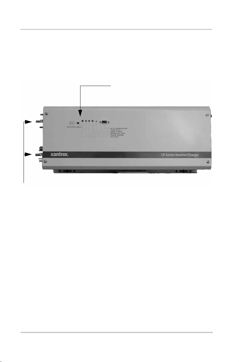
Front Panel Co ntrols and LED Indicato rs
Shown below are the c ontrols and i ndic ator li ghts on t he f ront
of the CR Serie s seri es. The y control a nd p rovide inf ormati on
in either inverter or battery charging mode of operation. All
models of the CR Series series operate identically.
Figure 3-1
Power On/Off
AC Mode LED
Control Panel
Once the CR Series has been properly installed and the
batteries are connected, press and hold the POWER ON/OFF
button (approximate ly 2-5 seconds) to turn the unit on or off.
This green LED lights up when the AC Input power is
qualified and passing through to the output (during charging).
21
Page 24

Operation
Battery Mode LED
This orange LED lights up when the unit is in battery mode
(using power from batteries).
Charger LED
Yellow This indicates that the charger is in the first stage
(constant current stage).
Blinking Yellow This indicates that the charger is in the
second stage (constant voltage stage). The LED blinks
approximately every 8-10 seconds.
F a iled (Fault) LED
Red light This indicat es that the inverter has shut down
from one of the following possible failures: overload, batt ery
voltage too high and fan failure. To restart the inverter, first
correct your fault and press a nd hold the ON/OFF POWER
button (approxim ately 2 – 5 seconds) to turn the unit back on.
Battery Bank Capacity
The BATTERY BANK CAPACITY control is used to inform
the microprocessor about the size of the battery bank being
used. Battery bank size is adjustable from 50 to > 500 amphours. Set this adjustment to the setting closest to the size of
your battery bank (in amp-hour s). The charge current will be
set at 0.1 times the battery bank setting up to the charging
maximum (see Table A-1).
22
Page 25

Audible Alarm (internal)
An alarm is located inside the unit as an audible alert for
warning and fault conditi ons. The Low Battery warning
causes the alar m to beep o nce ev ery 4.5 sec o nds an d the
110% Overlo ad condition warning causes the alarm to beep
continually. Faults, such as Battery Voltage Too High, Fan
Locked, Short Circuit and 150% Overload condition cause
the alarm to sound continuously. The Battery Undervoltage
fault causes the alarm to sound continuously until the unit
shuts down.
Circuit Breakers
The CR Series contains two circuit breakers located on the
right-hand side of the chas sis, directly above the AC input
terminal block. The I NVER TER OUTPUT PROTECT circuit
breaker protects the internal AC pass-through wiring and
transfer relay. The CHARGER INPUT PROTECT circuit
breaker protect s the charger circuit.
Front Pa nel Controls and LED Indicators
RS232 Communications
Used for factory testing. No customer interface is available.
23
Page 26

24
Page 27

A
Specifications
T ab le A- 1
MODEL
Nominal AC Input
Volt age
AC Input Disconnect
Volt age
Acceptable Voltage
Connect Range
Nominal AC Input
Frequency
AC Input Frequency
Range
Max Total AC Input
Current (Charge +
Bypass)
Rated AC Bypa ss
Current
Charging Voltage 12V model: 13.5Vdc
Charge and Bypass Mode Specifications
CR-1000
<85VAC or >132VAC, <184VAC or >253VACa ± 4%
95VAC — 127VAC / 194VAC — 243VAC
47Hz — 53Hza or 57Hz — 63Hz ± 0.3Hz
14 Arms at 120Vac
7.4 A r m s at 230Vac
8.3 Arms at 120Vac
4.4 A r m s at 230Vac
CR-1500 CR-2400
120VAC / 230VAC
60Hz or 50Hz
18.1 Arms at 120Vac
a
9.4 Arms at 230Vac
12.5 Arms at 120Vac
a
6.5 Arms at 230Vac
24V model: 27.0Vdc
a
a
a
a
a
27 Arms at 120Vac
14.1 Arms at 230Vac
20 Arms at 120Vac
10.4 Arms at 230Vac
a
a
Charging Current
(Depending on battery
capacity)
Relay Transfer Time 20 ms (typic al)
a. 230V, 50Hz m odels
12V model: 0 — 40A
24V model: 0 — 20A
12V model: 0 — 50A
24V model: 0 — 25A
25
Page 28

T ab le A- 2
Invert Mode Specifications
MODEL
AC Output Power
Nominal AC Output
CR-1000
1000VA / 1000W 1500VA / 1500W 2400VA / 2400W
CR-1500 CR-2400
120VAC / 230VAC
a
Volt age
AC Output Frequency 60Hz or 50Hza ± 0.3Hz
AC Output Waveform Modified Sinewave
Peak Efficiency (DC – AC) 86%
b
Nominal DC Input
12V or 24V
Volt age
DC Operating Range 12V models: 10.5V — 14.5V
24V models: 21V — 29V
Maximum DC Input
(to prevent damage)
DC Input Current at Full
Load
101 A at 12V
50 A at 24V
12V models: 15V
24V models: 30V
152 A at 12V
b
74 A at 24V
b
122 A at 24V
247 A at 12V
Surge Capability <1.5 times output power for 1 minute
Overload Shutdo wn >1.5 times outp ut power immediate shutdown
b
Low Battery Warning
(Audible Alarm)
12V model: 11V ± 0.5V
24V model: 22V ± 0.5V
Low Battery Shutdown 12V model: 10.5V ± 0.5V
24V model: 21V ± 0.5V
a. 230V, 50Hz m odels
b. 24Vdc models
26
Page 29

T ab le A- 3
Environmental and Physical Specifications
MODEL
Temperature 0 — 40°C Maximum (32 — 104°F)
Dimensions DxWxH 579 x 227 x 179mm (22.8in. x 8.9in. x 7in.)
Net W eight 18kg (40 lbs.) 20kg (44 lbs.) 27.5kg (61 lbs.)
T ab le A- 4
MODEL
RS-232 Port
Interface Specifications
CR-1000
CR-1000
Used for factory testing. No customer interface available.
CR-1500 CR-2400
CR-1500 CR-2400
27
Page 30

28
Page 31

Warranty Information
Limited Warranty for:
Xantrex CR Series Backup System Inverter ⁄ Charger
What does this warranty cover and how lo ng does it last? This Limited Warranty is
provided by X antrex Technol ogy Inc. ("Xantrex") and covers defects in workmanship and
materials in your Xantrex CR Series Series product. This warranty lasts for a Warranty Period
of 1 year from the date of purch ase at point of sale to you, the original end user customer.
What will Xantrex do? Xantrex will, at its opt ion, repair or replac e the defective product free
of charge, provided t hat you notify Xantrex of the pro duct defect wit hin the Warrant y Period,
and prov ided that X antrex through in spection e stablishes the exis tence of s uch a defect and t hat
it is covered by this Limited Warranty.
Xantrex wil l, at its option, use new and/or reconditioned parts in performin g wa rranty repa ir
and building replacement products. Xantrex reserves the right to use parts or products of
original or improved design in the repair or repla cement. If Xantrex repairs or replaces a
product, its warrant y continues for the remaining portion of the original Warranty Period or 90
days from the date of the return shipment to the customer, whichever is greater. All replaced
products and all parts rem oved from repaired products become the property of Xant rex.
How do you get ser vice?
If your pro duct require s troublesho oting or warranty servi ce, contact yo ur dealer. If you are
unable to co nta ct your d eal er , or th e deal er is unab le to provi de s er vice, con tact Xant re x dir ect ly
at:
Telephone: +34 93 470 5330 (Europe)
Fax: +34 93 473 6093 (Europe)
Email: support.europe@xantrex.com (Europe)
Web: www.xantrex.com
In any warra nty claim, dat ed proof of purchase must acco m pany the product and the produ ct
must not have been disassembled or modified without prior written authorization by Xantrex.
Proof of purchase may be in any one of the follow ing forms:
• The dated purchase receipt from the original purchase of the product at point of sale to the
end user, or
• The dated invoi ce or purchase receipt showin g the product exchanged under w arranty
What does th is warranty not cover? This Limited Warranty does not cover normal wear and
tear of the product or costs related to the removal, installation, or troubleshooting of the
customer 's electrical systems. Thi s warranty doe s not apply to and Xant rex will not be
responsible for any defect in or damage to:
a) the product if it has been misused, neg lected, improperly inst alled, physically
b) the product if it has been subjected to fire, water, excessive corrosion, biological
c) the product if repairs have been done to it other than by X antrex or its authorized
d) the product if it is u sed as a component part of a product expressly warranted by
1 360 925 5097 (Dir ect North America and rest of wo rld)
1 360 925 5143 (Dir ect North America and rest of wo rld)
customerservice@xantrex.com (North America and rest of world)
damaged or altered, either internally or externally, or damaged from improper use or
use in an unsuitable en vironment;
infestations, or input voltage that creates operating conditions beyond the maximum
or minimum limits listed i n the Xantrex pro duct specifications inc luding high inp ut
voltage from generator s and lightni ng strikes;
service centers (hereafter "ASCs");
another manufacturer;
29
Page 32

Warranty Information
e) the product if its original identification (trade-mark, serial number) markings have
been defac ed, altered, or removed.
DISCLAIMER OF WARRANTY
THIS LIMITED W ARRANTY IS THE SOLE AND EXCLUSIVE WARRANTY PROVIDED BY
XANTREX IN CONNECTION WITH YOUR XANTREX PRODUCT AND IS, WHERE PERMITTED
BY LAW, IN LIEU OF ALL OTHER WARRANTIES, CONDITIONS, GUARANTEES,
REPRESENTATIONS, OBLIGATIONS AND LIABILITIES, EXPRESS OR IMPLIED, STATUTOR Y
OR OTHERWISE IN CONNECTION WITH THE PRODUCT, HOWEVER ARISING (WHETHER BY
CONTRACT, TORT, NEGLIGENCE, PRINCIPLES OF MANUF AC TURER'S LIABILITY,
OPERA T ION OF LAW, CONDUCT, STATEMENT OR OTHERWISE), INCLUDING WITHOUT
RESTRICTION ANY IMPLIED WARRANTY OR CONDITION OF QUALITY, MERCHANT ABILITY
OR FITNESS FOR A PART ICULAR PURPOSE. ANY IMPLIED WARRANTY OF
MERCHANTABILITY OR FITNESS FOR A PARTICULAR PURPOSE TO THE EXTENT REQUIRED
UNDER APPLICABLE LAW TO APPLY TO THE PRODUCT SHALL BE LIMITED IN DURATION
TO THE PERIOD STIPULATED UNDER THIS LIMITED W AR RANTY.
IN NO EVENT WILL XANTREX BE LIABLE FOR ANY SPECIAL, INDIRECT, INCIDENTAL OR
CONSEQUENTIAL DAMAGES, LOSSES, COSTS OR EXPENSES HOWEVER ARISING WHETHER
IN CONTRACT OR TORT INCLUDING WITHOUT RESTRICTION ANY ECONOMIC LOSSES OF
ANY KIND, ANY LOSS OR DAMAGE TO PROPERTY, ANY PERSONAL INJURY, ANY DAMAGE
OR INJURY ARISING FROM OR AS A RESULT OF MISUSE OR ABUSE, OR THE INCORRECT
INST ALLATION, INTEGRATION OR OPERATION OF THE PRODUCT.
Exclusions This Limited Warranty gi ves you specific legal rights. You may have other rights
which may vary depending on the applicable law. Consumers have statutory rights under
applicab le national laws relating to the sale of consumer products. This wa rranty does not
affect statutory rights that you m ay have or your rights against the entity fro m which you
purchase d the product, and it does not curtail or limit those rights that cannot be excluded or
limited. Xa nt rex grant s a ll war ran ties pr escri bed by y our nat io nal st at utor y la w, provided that if
the Buyer is entitled to claim damages pursuant to the national law , Xantrex’s liability is
limited to the ful le st ex te nt as set out in thi s w ar ra n ty an d al lo w e d by law.
WITHOUT LIMITING THE GENERALITY OF THE FOREGOING, UNLESS SPECIFICALLY
AGREED TO BY IT IN WRITING, XANTREX
(a) MAKES NO WARRANTY AS TO THE ACCURACY, SUFFICIENCY OR SUITABILITY
OF ANY TECHNICAL OR OTHER INFORMATION PROVIDED IN MANUALS OR
OTHER DOCUMENTATION PROVIDED BY IT IN CONNECTION WITH THE
PRODUCT; AND
(b) ASSUMES NO RESPONSIBILITY OR LIABILITY FOR L OSSES, DAMAGES, COS TS OR
EXPENSES, WHETHER SPECIAL, DIRECT, INDIRECT, CONSEQUENTIAL OR
THE USE OF ANY SUCH INFORMATION WILL BE ENTIRELY A T THE USER'S RISK.
INCIDENTAL, WHICH MIGHT ARISE OUT OF THE USE OF SUCH INFORMATION.
WARNING: LIMITATIONS ON USE
Please refer to your product user manual for limitations on uses of the product. Specifica lly,
please no te that the CR Series Seri es is not intended for use in connection with life support
systems and Xantrex makes no warranty or represe ntation in con nection with any use of the
product for such purposes.
Xantrex Technology, Inc.
8999 Nelson Way
Burnaby , British Columbia
Canada V5A 4B5
30
Page 33

s
Page 34

Xantrex Technology Inc.
Telephone: +34 93 470 5330 (Europe)
1 360 925 5097
(North America and rest of world)
Fax: +34 93 473 6093 (Europe)
1 360 925 5143
(North America and rest of world)
Email: support.europe@xantrex.com
(Europe)
customerservice@xantrex.com
(North America and rest of world)
Web: www.xantrex.com
Printed in China
 Loading...