

Page 1
Communications
Gateway
Installation Guide
Communications Gateway
Inverter
Modbus /RS485
Page 2

Page 3

Communications Gateway
Installation Guide
Page 4

About Xantrex
Xantrex Technology Inc. is a world-leading supplier of advanced power electronics and controls with
products ranging from small mobile units to utility-scale systems for wind, solar, batteries, fuel cells,
microturbines, and backup power applications in both grid-connected and stand-alone systems. Xantrex
products include inverters, battery chargers, programmable power supplies, and variable speed drives
that convert, supply, control, clean, and distribute electrical power.
Trademarks
Xantrex is a registered trademark of Xantrex International.
Other trademarks, registered trademarks, and product names are the property of their respective owners
and are used herein for identification purposes only.
Notice of Copyright
Communications Gateway Installation Guide © January 2008 Xantrex International. All rights
reserved.
Exclusion for Documentation
UNLESS SPECIFICALLY AGREED TO IN WRITING, XANTREX TECHNOLOGY INC. (“XANTREX”)
(
A) MAKES NO WARRANTY AS TO THE ACCURACY, SUFFICIENCY OR SUITABILITY OF ANY TECHNICAL OR
OTHER INFORMATION PROVIDED IN ITS MANUALS OR OTHER DOCUMENTATION.
(
B) ASSUMES NO RESPONSIBILITY OR LIABILITY FOR LOSSES, DAMAGES, COSTS OR EXPENSES, WHETHER
SPECIAL, DIRECT, INDIRECT, CONSEQUENTIAL OR INCIDENTAL, WHICH MIGHT ARISE OUT OF THE USE OF
SUCH INFORMATION. THE USE OF ANY SUCH INFORMATION WILL BE ENTIRELY AT THE USER’S RISK; AND
(C) REMINDS YOU THAT IF THIS MANUAL IS IN ANY LANGUAGE OTHER THAN ENGLISH, ALTHOUGH
STEPS HAVE BEEN TAKEN TO MAINTAIN THE ACCURACY OF THE TRANSLATION, THE ACCURACY CANNOT
BE GUARANTEED. APPROVED XANTREX CONTENT IS CONTAINED WITH THE ENGLISH LANGUAGE
VERSION WHICH IS POSTED AT WWW.XANTREX.COM.
Date and Revision
January 2008 Revision B
Part Number
975-0330-01-01
Product Number
865-1055 (North America), 865-1056 (Europe)
Contact Information
Telephone: 1 800 670 0707 (toll free North America)
1 408 987 6030 (direct)
Fax: 1 800 994 7828 (toll free North America)
1 360 925 5143 (direct)
Email: customerservice@xantrex.com
Web: www.xantrex.com
Page 5

iii
About This Guide
Purpose
This Installation Guide provides explanations and procedures for
installing and configuring the Communications Gateway.
Scope
The Guide provides safety guidelines and procedures for installing and
configuring the Gateway. It does not provide detailed information about
the underlying Xanbus or Modbus protocol.
Audience
The Guide is intended for anyone who needs to install and configure the
Communications Gateway. Installers should be qualified electricians or
service technicians. Once installed, the Gateway can be configured by a
service technician or an end user.
Organization
This Guide is organized into three chapte rs an d one app e ndi x.
Chapter 1, “Introduction” contains information about the features and
functions of the Communications Gateway.
Chapter 2, “Installation” contains information and procedures to install
the Communications Gateway.
Chapter 3, “Configuration” contains information and procedures to
configure the Communications Gateway.
Chapter 4, “Troubleshooting” contains reference information you can
consult if you have problems using the Communications Gateway. This
chapter also lists routers that have been tested with the Gateway.
Note: This manual documents features and operation of the Xantrex base
model Gateway. Gateways installed by second-party service providers (OEMs)
may incorporate modified features and functions that are not described in this
manual.
Page 6
About This Guide
iv 975-0330-01-01
Appendix A, “Specifications” contains electrical, mechanical and
regulatory specifications for the Communications Gateway.
Conventions Used
The following conventions are used in this guide.
Related Information
You can find more information about Xantrex Technology Inc. as well as
its products and services at www.xantrex.com.
WARNING
Warnings identify conditions or practices that could result in personal injury or
loss of life
CAUTION
Cautions identify conditions or practices that could result in damage to the unit or
other equipment.
Important:
These notes describe things which are important for you to know,
but not as serious as a caution or warning.
Page 7

v
Important Safety Instructions
General Precautions
1. Before installing and using this device, read all appropriate sections
of this guide and any cautionary markings on the Gateway and the
devices to which it connects.
2. Do not dismantle the Gateway; it contains no user serviceable parts.
3. Protect the Gateway from rain, snow, spray, and water. A
recommended outdoor enclosure is available from Xantrex.
4. Use only accessories recommended or sold by the manufacturer.
Doing otherwise may result in a risk of fire, electric shock, or injury
to persons.
WARNING: Read and save these instructions
This Installation Guide contains important safety and operating instructions.
Before using your Communications Gateway, be sure to read, understand, and
save these safety instructions.
WARNING: Shock and energy hazards
Connecting the Gateway to other equipment may require access to wiring
compartments containing circuits that are shock and/or energy hazards. Refer to
this manual and the manual provided with the other equipment, and to any
warning or caution labels on the equipment. Be sure to disconnect all sources of
power to the equipment before working near its wiring terminals.
Note that in some cases hazardous voltage may still be present at the input to the
equipment, ahead of the disconnecting means. Any guards or barriers provided to
prevent inadvertent contact with live parts must be left in place.
Protection Class III: All circuits in this product are non-hazardous Safety Extra
Low Voltage when connected only to Xanbus or Ethernet networks. Connect
only to the circuit recommended in this manual.
Page 8

vi 975-0330-01-01
FCC Information to the User
This equipment has been tested and found to comply with the limits for a
Class B digital device, pursuant to part 15 of the FCC Rules. These limits are
designed to provide reasonable protection against harmful interference when
the equipment is operated in a residential environment. This equipment
generates, uses and can radiate radio frequency energy and, if not installed
and used in accordance with the instruction guide, may cause harmful
interference to radio communications. However, there is no guarantee that
interference will not occur in a particular installation. If this equipment does
cause harmful interference to radio or television reception, which can be
determined by turning the equipment off and on, the user is encouraged to try
to correct the interference by one or more of the following measures:
• Reorient or relocate the antenna.
• Increase the separation between the equipment and the receiver.
• Connect the equipment to a circuit different from that to which the
receiver is connected.
• Consult the dealer or an experienced radio/TV technician for help.
This equipment contains a radio transmitter with the following ID number s:
• FCC: R68WIPORT
• Industry Canada: 2867A-WIPORT
Wireless Networking Security
This device can be configured to connect to the Internet using wireless
technology. As with all such devices, if you do not properly set up a
wireless security system others can get unauthorized access to your
Internet connection and possibly to personal information contained on
your computer network.
Product Recycling
Do not dispose of this product with general household waste!
Electrical appliances marked with the symbol shown must be professionally
treated to recover, reuse, and recycle materials, in order to reduce negative
environmental impact. When the product is no longer usable, European
consumers are legally obligated to ensure that it is collected separately under
the local electronics recycling and treatment scheme.
Page 9

975-0330-01-01 vii
Important Safety Instructions
- - - - - - - - - - - - - - - - - - - - - - - - - - - - - - - - - - -v
1
Introduction
Gateway Overview - - - - - - - - - - - - - - - - - - - - - - - - - - - - - - - - - - - - - - - - - - - - -1–2
External Features - - - - - - - - - - - - - - - - - - - - - - - - - - - - - - - - - - - - - - - - - - - - - - 1–3
Types of Gateway Networks- - - - - - - - - - - - - - - - - - - - - - - - - - - - - - - - - - - - - - - 1–5
Local Area Network - - - - - - - - - - - - - - - - - - - - - - - - - - - - - - - - - - - - - - - - - 1–5
Gateway with Remote Access - - - - - - - - - - - - - - - - - - - - - - - - - - - - - - - - - -1–7
2
Installation
Installing the Gateway- - - - - - - - - - - - - - - - - - - - - - - - - - - - - - - - - - - - - - - - - - -2–2
Choosing a Location - - - - - - - - - - - - - - - - - - - - - - - - - - - - - - - - - - - - - - - - -2–3
Materials and Tools Required - - - - - - - - - - - - - - - - - - - - - - - - - - - - - - - - - - - 2–4
Supplied Materials - - - - - - - - - - - - - - - - - - - - - - - - - - - - - - - - - - - - - - - 2–4
Other Materials and Tools - - - - - - - - - - - - - - - - - - - - - - - - - - - - - - - - - -2–5
Mounting the Gateway - - - - - - - - - - - - - - - - - - - - - - - - - - - - - - - - - - - - - - - 2–5
Connecting the Gateway to a Router or Computer - - - - - - - - - - - - - - - - - - - - - 2–6
Connecting the Gateway to the Xanbus Network - - - - - - - - - - - - - - - - - - - - - - 2–6
Network Layout - - - - - - - - - - - - - - - - - - - - - - - - - - - - - - - - - - - - - - - - - 2–8
Guidelines for Routing the Network Cables - - - - - - - - - - - - - - - - - - - - - - 2–8
Connecting the Gateway to a GT Inverter - - - - - - - - - - - - - - - - - - - - - - - -2–9
Connecting the Gateway to a XW Hybrid Inverter/Charger - - - - - - - - - - - 2–10
Applying Power to the Gateway - - - - - - - - - - - - - - - - - - - - - - - - - - - - - - - - 2–11
Adding Devices to the Network - - - - - - - - - - - - - - - - - - - - - - - - - - - - - - - - - - - 2–11
Installing Yahoo! Widgets - - - - - - - - - - - - - - - - - - - - - - - - - - - - - - - - - - - - - - - 2–12
3
Configuration
Configuring the Gateway - - - - - - - - - - - - - - - - - - - - - - - - - - - - - - - - - - - - - - - - -3–2
Viewing the Configuration Web Page - - - - - - - - - - - - - - - - - - - - - - - - - - - - - - - - 3–2
Using the Solar Monitor Widget - - - - - - - - - - - - - - - - - - - - - - - - - - - - - - - - -3–3
Finding the Gateway IP Address Manually - - - - - - - - - - - - - - - - - - - - - - - - - - 3–5
Finding the Gateway IP Address with No Router in the System - - - - - - - - - - - - 3–7
Contents
Page 10

Contents
viii 975-0330-01-01
Using the Configuration Web Page - - - - - - - - - - - - - - - - - - - - - - - - - - - - - - - - - - 3–8
Entering Your Basic Information - - - - - - - - - - - - - - - - - - - - - - - - - - - - - - - - 3–9
Renaming Devices - - - - - - - - - - - - - - - - - - - - - - - - - - - - - - - - - - - - - - - - - - 3–9
Configuring the Gateway for Your Network - - - - - - - - - - - - - - - - - - - - - - - - 3–10
Configuring Wireless Mode - - - - - - - - - - - - - - - - - - - - - - - - - - - - - - - - - - - 3–12
Configuring Network Time - - - - - - - - - - - - - - - - - - - - - - - - - - - - - - - - - - - 3–14
Configuring Email - - - - - - - - - - - - - - - - - - - - - - - - - - - - - - - - - - - - - - - - - 3–16
Upgrading Device Firmware - - - - - - - - - - - - - - - - - - - - - - - - - - - - - - - - - - 3–17
Resetting the Gateway to Factory Defaults - - - - - - - - - - - - - - - - - - - - - - - - - - - - 3–19
Power System Monitoring on the Internet- - - - - - - - - - - - - - - - - - - - - - - - - - - - - 3–20
4
Troubleshooting
Device Discovery- - - - - - - - - - - - - - - - - - - - - - - - - - - - - - - - - - - - - - - - - - - - - - 4–2
Loss of Communication - - - - - - - - - - - - - - - - - - - - - - - - - - - - - - - - - - - - - - - - - 4–3
Email Messages - - - - - - - - - - - - - - - - - - - - - - - - - - - - - - - - - - - - - - - - - - - - - - - 4–4
Miscellaneous Issues- - - - - - - - - - - - - - - - - - - - - - - - - - - - - - - - - - - - - - - - - - - - 4–5
Router Compatibility - - - - - - - - - - - - - - - - - - - - - - - - - - - - - - - - - - - - - - - - - - - 4–6
A
Specifications
Electrical Specifications - - - - - - - - - - - - - - - - - - - - - - - - - - - - - - - - - - - - - - - - -A–2
Communication Specifications - - - - - - - - - - - - - - - - - - - - - - - - - - - - - - - - - - - - -A–2
History Data Storage- - - - - - - - - - - - - - - - - - - - - - - - - - - - - - - - - - - - - - - - - - - -A–2
Mechanical Specifications - - - - - - - - - - - - - - - - - - - - - - - - - - - - - - - - - - - - - - - -A–3
Environmental Specifications- - - - - - - - - - - - - - - - - - - - - - - - - - - - - - - - - - - - - -A–4
Regulatory Compliance- - - - - - - - - - - - - - - - - - - - - - - - - - - - - - - - - - - - - - - - - -A–4
Warranty and Return Information
- - - - - - - - - - - - - - - - - - - - - - - - - - - WA–1
Index
- - - - - - - - - - - - - - - - - - - - - - - - - - - - - - - - - - - - - - - - - - - - - - - - - - - - - - - IX–1
Page 11

1
Introduction
Chapter 1, “Introduction” contains information about
the features and functions of the Communications
Gateway.
This chapter covers the following topics:
• “Gateway Overview”
• “External Features”
• “Types of Gateway Networks”
Page 12

Introduction
1–2 975-0330-01-01
Gateway Overview
The Communications Gateway is the central component for a residential
power monitoring system. The Gateway communicates with Xantrex GT
Solar Inverters and XW Hybrid Inverter/Chargers and transmits a unified
view of system performance to a computer-based power monitoring
application.
On one side, the Gateway directly communicates with a Xantrex inverter
using Xanbus™, a CAN-based network communication protocol
developed by Xantrex. The Gateway converts Xanbus messages to
Modbus messages, and transmits the converted inverter performance data
for monitoring. On the other side, the Gateway’s WiFi/Ethernet module
provides an interface to monitor system performance on a personal
computer. Computer-based monitoring can be performed on your Local
Area Network or using the Internet from any location.
The Gateway features include a standard plug-in WiFi/Ethernet module
with 10/100 Base-T or 802.11b/g, and:
• Embedded web services to support Yahoo! W idgets. Xantrex provides
a Solar Monitor Widget to display data transmitted by the Gateway.
• Embedded web page for configuring the Gateway and upgrading
device firmware.
The Gateway logs and transmits performance data such as:
• Power system energy production
• Individual inverter energy production
• Energy production history—daily, weekly, monthly
• Inverter faults.
To view this production data, you must install the Xantrex Solar Monitor
Widget and configure the Gateway to communicate with your computer
or computer network. Other means of viewing Gateway-transmitted data
will be available from Xantrex in the future. For more information about
Gateway data storage, see “History Data Storage” on page A–2.
Note: The Gateway provides performance data only from the time it is
connected to your power system. The Gateway cannot be calibrated to match
existing power production totals for a power system that has been operating
without a Gateway. When connected to an existing power system, the Gateway
power production totals will differ from the totals displayed by older inverters
or devices in the system.
Page 13
External Features
975-0330-01-01 1–3
External Features
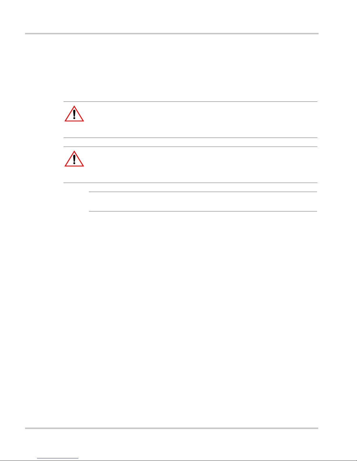
Figure 1-1
Gateway Front
Item Description
1 Inverter LED indicates overall status of the network between the
Gateway and the inverters. The LED blinks in three colors:
• Green: the network is working properly
• Yellow: the Gateway has detected errors on the network
• Red: the Gateway has stopped communicating in the network.
2 Modbus/RS485 LED indicates message transmission between the
Gateway and an Internet protocol-connected computer. The LED
blinks during regular operation. The LED is on steadily when the
Gateway is upgrading device software or the Gateway is in bootloader
mode and requires its own software to be loaded. See “Upgrading
Device Firmware” on page 3–17.
3 Antenna for the wireless Internet protocol connection.
Communications Gateway
Inverter
Modbus /RS485
1
2
3
Page 14

Introduction
1–4 975-0330-01-01
Figure 1-2
Gateway Bottom
Item Description
1 Inverter (Xanbus RJ-45) ports for connecting the inverter and other
Xanbus devices to the Gateway.
Caution: see “Equipment damage” below.
2 Ethernet port for connecting the Gateway to a router or computer.
Caution: see “Equipment damage” below.
3 WiFi Antenna.
4 Reset button. The Reset button returns the Gateway to its default
settings. See “Resetting the Gateway to Factory Defaults” on page 3–
19.
5 RS-485 port for connecting Modbus-equipped devices (do not use—
not supported at this time).
6 Zigbee (RJ-11 ) port (do not use—not supported at this time).
CAUTION: Equipment damage
Although the cables and connectors that connect the Gateway to the Xanbus
network are identical to Ethernet cables and connectors, the communication
interface is not Ethernet. It is based on CAN bus and also supplies the Xanbus
network devices with DC power. The DC power in the Xanbus network is not
compatible with Ethernet. Personal computers or routers may be dam a g e d if
connected directly to powered Gateway Inverter ports. The Gateway can be
damaged if a powered Xanbus cable is connected to the Ethernet port.
Inverter
WARNING!
Not for computer
RS485
Ethernet
Zigbee
12 4563
Page 15
Types of Gateway Networks
975-0330-01-01 1–5
Types of Gateway Networks
The Gateway can interface with different devices with wired or wireless
connections to provide several options for monitoring your power system
performance.
Local Area Network
The Gateway provides performance data for display on a home computer.
Data is displayed using the Solar Monitor Widget, available free from
Xantrex.
Connections between the Gateway, router and computer can be wired or
wireless, but not both at the same time. An Ethernet connection between
the Gateway and router or computer is required for initial installation and
configuration, after which the Gateway can be set to wireless mode and
the cable removed.
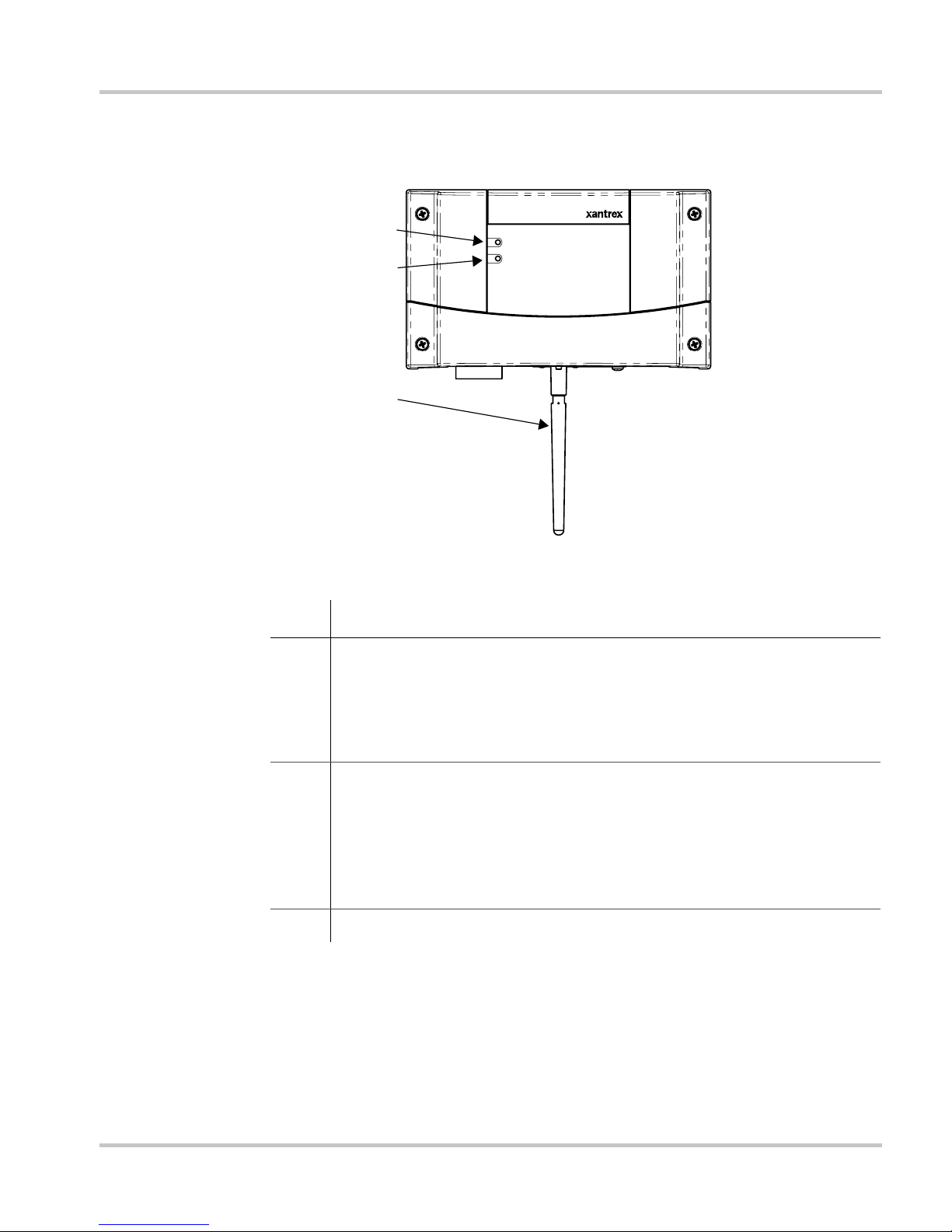
Figure 1-3
Default Wired Network
Xanbus cable
Inverter
Gateway
Router
Home computer
with Widget
Ethernet connection
Page 16
Introduction
1–6 975-0330-01-01
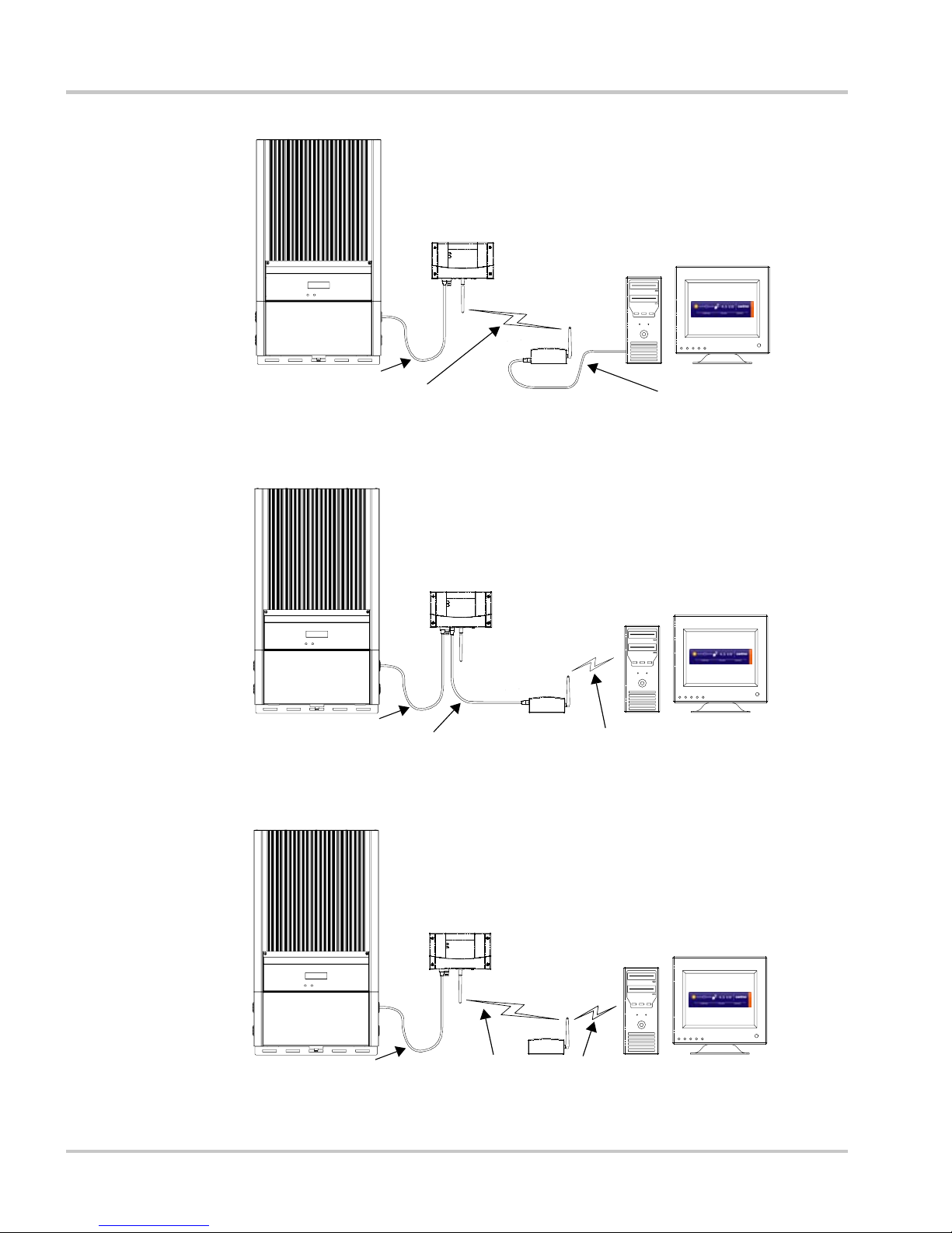
Figure 1-4
Mixed Wired/Wireless Network 1
Figure 1-5
Mixed Wired/Wireless Network 2
Figure 1-6
Wireless Network With Router
Xanbus cable
Inverter
Gateway
Router
Home computer
with Widget
Ethernet Connection
Wireless Internet Protocol connection
Xanbus cable
Inverter
Gateway
Router
Home computer
with Widget
Ethernet connection
Wireless Internet Protocol connection
Xanbus cable
Inverter
Gateway
Router
Home computer
with Widget
Wireless Internet Protocol connection
Page 17
Types of Gateway Networks
975-0330-01-01 1–7
Gateway with Remote Access
To view power system pe rformance data on a remote computer using the
Internet from any location, you must connect the Gateway to a router and
change your router firewall settings to allow “port forwarding.” Port
forwarding enables a computer from an external IP address (elsewhere on
the Internet) to view Gateway data. Port forwarding allows you to specify
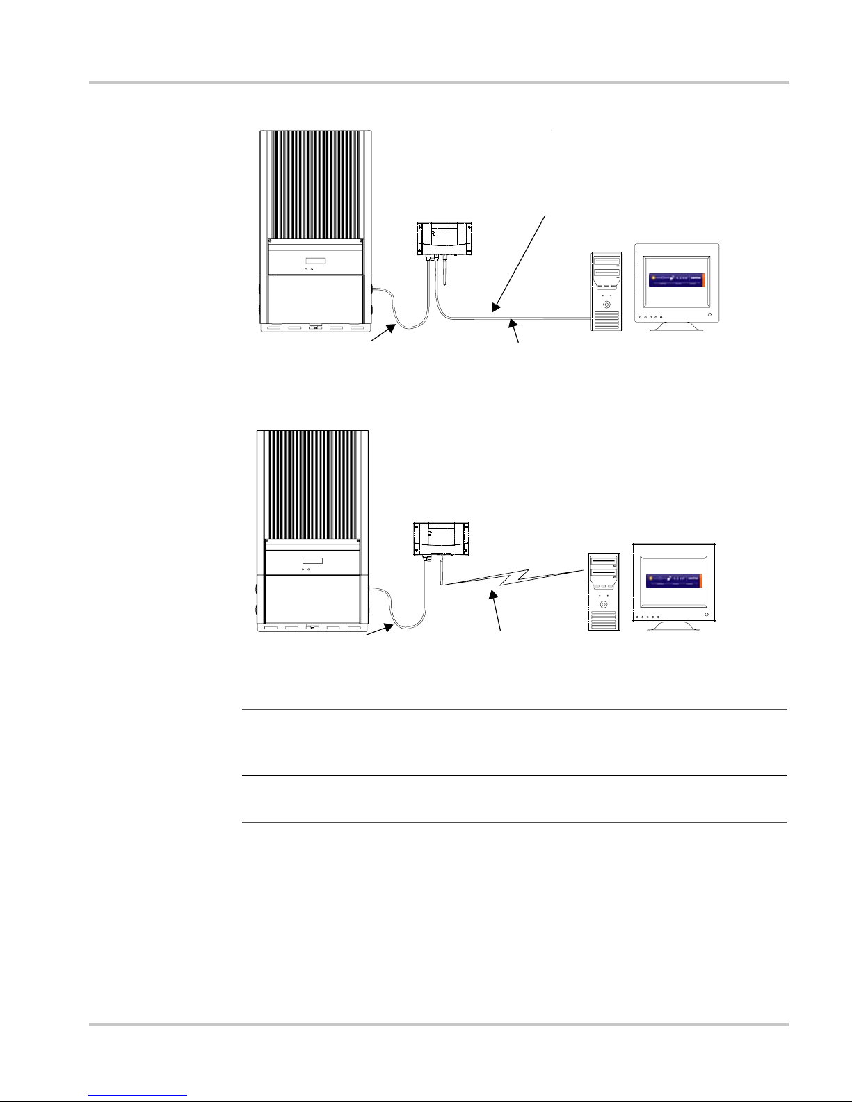
Figure 1-7
Wired Network Without Router
Figure 1-8
Wireless Network Without Router
Important:
Figure 1-7 and Figure 1-8 are “Ad-Hoc” networks that do not
allow access to the Internet. For more information, see “Configuring Wireless
Mode” on page 3–12.
Important:
The wired connections shown in Figure 1-3, Figure 1-5 and
Figure 1-7 are required for initial system configuration.
Xanbus cable
Inverter
Gateway
Home computer
with Widget
Ethernet connection
Crossover cable is
required for the
Gateway-to-computer
connection.
Xanbus cable
Inverter
Gateway
Home computer
with Widget
Wireless Internet Protocol connection
Page 18
Introduction
1–8 975-0330-01-01
how and where Gateway data is directed through your router so that you
can view that data from an Internet-connected computer anywhere in the
world.
For more information, see the Gateway configuration web page
(“Viewing the Configuration Web Page” on page 3–2) and “Power
System Monitoring on the Internet” on page 3–20.
If you simply want to monitor your power system on your home network,
you do not need to change your firewall settings.
CAUTION: Computer Security Risk
Changing your router’s firewall settings to allow port forwarding can potentially
leave your home network open to attacks from external computers. Do not
change your firewall settings unless you are absolutely sure of how to do it
correctly. The PORT Forward web site (www.portforward.com) has collected
information on how to configure most popular routers. Xantrex does not provide
any guarantees as to the security of your network if you follow the advice
provided at the PORT Forward web site. Use at your own risk.
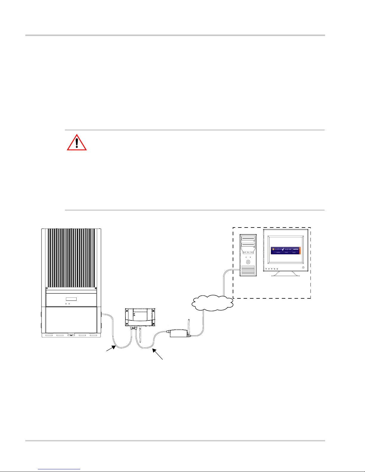
Figure 1-9
Gateway with Widget and Remote Access
Inverter
Gateway
Router
Remote computer
with Widget
Xanbus to Gateway
Ethernet or Wireless Internet
Protocol connection
Internet
Page 19

2
Installation
Chapter 2, “Installation” contains information and
procedures to install the Communications Gateway.
Gateway installation includes mounting the Gateway,
then connecting it to a computer network and to the
Xanbus network.
Page 20

Installation
2–2 975-0330-01-01
Installing the Gateway
This chapter assumes that one or more inverters are already installed, and
that multiple inverters are already connected with network cables. For
more information about installing a multiple-inverter network, see:
• For GT Inverters: “Communications Wiring for Multiple Inverters” in
the Solar Inverter Owner’s Manual
• For XW Hybrid Inverter/Chargers: The XW Power System
Installation Guide.
Installing the Gateway consists of the following steps:
1. Choosing a Location.
2. Mounting the Gateway.
3. Connecting the Gateway to a router (your local area network) or
computer.
4. Connecting the Gateway to the Xanbus network.
Connecting the Gateway to the Xanbus network also applies power to
the Gateway.
5. Installing Yahoo! Widgets (also known as Konfabulator or Yahoo!
Widget Engine) and Solar Monitor Widget on your computer.
The Solar Monitor Widget displays power system performance data
transmitted from the Gateway.
WARNING: Shock and energy hazards
Connections to other equipment may require accessing wiring compartments
containing circuits that are shock or energy hazards. In such cases, ensure that
sources of power are disconnected. Installation should be done only by a
qualified installer or electrician.
Important:
Apply power to the Gateway only after connecting it to the local
area network in the previous step. This ensures that the Gateway can acquire an
IP address quickly, and does not first acquire a default address that it must reject
after a time-out period.
Page 21

Installing the Gateway
975-0330-01-01 2–3
Choosing a Location
Choose a clean, dry, easily accessible location. Indoor installations are
recommended. For outdoor installations, mount the Gateway inside a
weatherproof enclosure. A recommended outdoor mounting enclosure is
available from Xantrex (part number 864-0500).
Minimum
clearance
To comply with FCC and Industry Canada regulations, the Gateway must
be installed in a location where the antenna is at least 8 inches (200 mm)
away from people and any other antenna.
Maximum
distance
between
devices
Distance and orientation are important factors to consider when installing
a wireless network. In testing, the Gateway has delivered acceptable
performance under optimal conditions up to 300 feet (90 meters) away
from another wireless device. Many factors can affect network
performance, including house construction, antenna orientation, and
distance between devices.
For best performance, a wired Ethernet connection between the Gateway
and the Internet router is recommended.
Important:
During Gateway configuration, you must connect the Gateway to
the router or computer with an Ethernet cable. After the Gateway has established
network connections, you can configure the Gateway for wireless mode, after
which you can remove the cable between the Gateway and the router.
Table 2-1
Distances Between Gateway and Other Devices
Connection Type
Maximum Distance (Approximate)
Wired Wireless
Inverter to Gateway 130 ft (40 m) n/a
Gateway to Router 200 ft (60 m) 300 ft (90 m)
Page 22

Installation
2–4 975-0330-01-01
Materials and Tools Required
The following materials and tools are required to install the Gateway.
Supplied Materials
p Gateway
p 10 ft (3 m) Xanbus network cable (standard straig ht-through Ethernet
cable—CAT 5e)
p Four #6 screws
p Network terminators (supplied with the Gateway and the inverter).
Figure 2-1
Maximum Distances Between Devices
130 ft
(40 m)
300 ft
(90 m)
(Wireless)
Varies
with
router
Router
Personal Computer
Gateway
Inverter
CAUTION: Equipment damage
Do not use crossover cable for the Xanbus network cable. On crossover cable, the
order of color-coded wires at each end of the cable is different.
Page 23

Installing the Gateway
975-0330-01-01 2–5
Other Materials and Tools
p Additional Ethernet cable (for connecting the Gateway to a router) or
crossover cable (when connecting the Gateway directly to a
computer)
p Xanbus power supply (required when connecting the Gateway to a
single GT Inverter manufactured before spring 2008)
For a network power supply, contact Xantrex at 1 800 670-0707 or
customerservice@xantrex.com.
p Weatherproof enclosure (required for outdoor installations, part
number 864-0500)
p Phillips screwdriver
p Power drill
p Cable clamps or hardware fasteners.
Mounting the Gateway
Indoors Mount the Gateway on a wall with the connectors facing downwards. For
Gateway dimensions, see Figure A-1 on page A–3.
To mount the Gateway:
1. Hold the unit flush and square against the wall, panel, or horizontal
surface.
• If the mounting surface requires pre-drilled holes for the screws,
use the supplied mounting template to mark, then drill, four
holes.
2. With a Phillips screwdriver and the supplied #6 screws, secure each
corner of the Gateway to the mounting surface.
Outdoors Outdoor Gateway installations require the Gateway to be mounted inside
a weatherproof enclosure. A Gateway weatherproof enclosure (part
number 864-0500) is available from Xantrex.
Page 24

Installation
2–6 975-0330-01-01
Connecting the Gateway to a Router or Computer
To connect the Gateway to a router:
u Connect a standard Ethernet cable from the Gateway Ethernet port to
an open network port on your router.
Do not connect the Gateway to the router port labeled “Internet” or
“WAN.”
To connect the Gateway directly to a computer:
u Connect a crossover cable from the Gateway Ethernet port to an open
network port on your computer.
Connecting the Gateway to the Xanbus Network
A Xanbus network consists of the following components:
• Xanbus-enabled devices—these include the Gateway, the GT
Inverter, the XW Series Inverter/Charger, XW Automatic Generator
Start (AGS), System Control Panel (SCP), and XW Charge
Controller. The maximum number of devices on the network depends
on the type of device. For example, the Gateway can monitor a
network consisting of up to 20 G T Inverters (up to five GT Inverters if
a GT Solar Inverter Monitor is installed) or an XW Power System
with up to three XW Inverter/Chargers, two Charge Controllers, an
AGS, SCP, and Gateway. (This is the current maximum size of an
XW Power System. Future XW releases will allow more than three
XW Series Inverter/Chargers to operate in a Xanbus network.)
In systems that combine GT and XW inverters, treat an XW Series
Inverter/Charger as the equivalent of four GT Inverters. XW inverters
transmit up to four times as much network data as a GT Inverter.
• Xanbus power supply—the inverter or inverter/charger provides
network power.
Important:
During setup, a wired connection between the Gateway and the
router is required. During configuration, the Gateway can be switched to wireless
mode and the network cable can be removed. See “Configuring Wireless Mode”
on page 3–12.
Important:
Connecting the Gateway to the Xanbus network also applies
power to the Gateway. Before making the final connection to the Gateway, see
“Applying Power to the Gateway” on page 2–11.
Page 25

Installing the Gateway
975-0330-01-01 2–7
• Xanbus cables—each Xanbus-enabled device is connected by a
standard Ethernet (CAT 5e) cable. A 10 foot (3 meter) network cable
is included with the Gateway. If more cables or a different length are
required, these standard cables can be purchased from Xantrex or any
computer supply store.
• Network terminators (Figure 2-2)—the Xanbus network must be
properly terminated at each end with network terminators. If the
network is not properly terminated, signal quality is degraded and
performance on the network is reduced. Permanent configuration
without terminators is not supported by Xantrex. One terminator is
included with the Gateway. Depending on your network layout, this
terminator may need to be inserted into another device elsewhere in
the network.
Important:
If the Gateway is connected to a single GT Inverter manufactured
before spring 2008, then an external Xanbus power supply must be added to the
system. XW Hybrid Inverter/Chargers or any multiple GT Inverter installation
can provide sufficient network power.
CAUTION: Equipment damage
Do not use crossover cable. On crossover cable, the order of color-coded wires at
each end of the cable is different.
Figure 2-2
Network Terminator
Page 26

Installation
2–8 975-0330-01-01
Network Layout
Xanbus-enabled devices are linked with separate lengths of Xanbus cable,
as shown in Figure 2-3.
T o ensure communication signal quality, each end of the network must be
terminated. The Xanbus-enabled devices at each end of the network must
have a male terminator inserted into their open network ports.
If the Gateway is the last device on the network, the open Inverter port on
the Gateway must be terminated. See Figure 2-3.
Guidelines for Routing the Network Cables
To ensure maximum performance of your network, follow these
guidelines when routing the network cables.
• Route the cables away from sharp edges that might damage the
insulation.
Figure 2-3
Network Layout Diagram
:
WARNING: Shock hazard
Do not route the network cables in the same conduit as the AC and DC power
cabling. When connecting and routing the network cable in the inverter wiring
box, make sure the network cable is physically separated from the AC and DC
power cables and any bare live parts by a barrier or by wire routing and securing
means.
Terminator
Terminator
GT Inverters shown with
wiring box covers removed.
Xanbus cable
Ethernet cable
Page 27

Installing the Gateway
975-0330-01-01 2–9
• Allow for some slack in the cable tension.
• Do not staple the cable outside the inverter with metal cable staples.
Use the appropriate hardware fasteners to avoid damage to the cable.
Connecting the Gateway to a GT Inverter
The GT Inverter is equipped with two Xanbus (RJ-45) network ports
inside the wiring box. See Figure 2-4. Follow the guidelines for
connecting devices and terminating the network as described in “Network
Layout” on page 2–8, and in “Communications Wiring for Multiple
Inverters” in the GT Inverter Owner’s Manual.
CAUTION: Unpredictable device behavior
Do not connect one end of the network to the other to make a ring or loop.
CAUTION: Equipment damage
Although the cables and connectors that connect the Gateway to the Xanbus
network are identical to Ethernet cables and connectors, the communication
interface is not Ethernet. It is based on CAN bus and also supplies the Xanbus
network devices with DC power. The DC power in the Xanbus network is not
compatible with Ethernet. Personal computers or routers will be damaged if
connected directly to powered Gateway Inverter ports. The Gateway can be
damaged if a powered Xanbus cable is connected to the Ethernet port.
Figure 2-4
GT Inverter Xanbus (RJ-45) Ports
Xanbus (RJ-45) ports
Terminator
Page 28

Installation
2–10 975-0330-01-01
Connecting the Gateway to a XW Hybrid Inverter/Charger
The XW Hybrid Inverter/Charger is equipped with two Xanbus netwo rk
ports (see Figure 2-5). These ports may not be immediately accessible if a
conduit box is installed on the bottom of the inverter/charger. Follow the
guidelines for connecting devices and terminating the network as
described in “Network Layout” on page 2–8, and in “ Xanbus Network
Installation” in the XW Power System Installation Guide.
Figure 2-5
XW Inverter/Charger Xanbus Ports
CHASSIS
GROUND
AC SYNC
XANBUS
BTS
AUX
POS
NEG
REFER TO MANUAL
270-1407-01-01
TIGHTENING TORQUE
#6 - #4: 45 in-lbs
#2 - 1/0: 50 in-lbs
TIGHTEN TO
15-16 ft-lbs
270-1408-01-01
Xanbus ports
Page 29

Adding Devices to the Network
975-0330-01-01 2–11
Applying Power to the Gateway
The Gateway gets its power from the Xanbus network through the
network cable. When applying power to the Gateway by connecting the
network cable, ensure that the Xanbus network itself has power. The
inverter or inverter/charger supplying power to the Xanbus network must
be operating.
If connecting the Gateway to a GT Inverter, ensure that the GT Inverter
DC/AC disconnect switch is in the ON position. The GT Inverter LCD
should be on.
If connecting the Gateway to an XW Hybrid Inverter/Charger , ensure that
the inverter/charger is operating. The Inverter Information Panel should
be illuminated.
To apply power to the Gateway:
u Plug the Xanbus network cable from th e network into an Inverter port
on the Gateway.
After connecting the Gateway to the Xanbus network, the Gateway
performs a power-up test. The Inverter LED lights up green for 1 second,
the Modbus LED lights up yellow for 1 second, then the Inverter LED
lights up red 1 second. During normal operation the Inverter LED blinks
green and the Modbus LED blinks occasionally.
The Inverter LED blinks green if the Xanbus network is working
properly. It blinks yellow or red if there is a problem with the network.
The Modbus LED flashes when an external device requests data from the
Gateway.
Adding Devices to the Network
The Xanbus network is expandable. Before installing additional inverters
or other network devices, follow these guidelines.
• Close the Solar Monitor Widget if it is running. If the Widget detects
a device dropping off the network due to a disconnected networ k
cable, it issues an error message.
• Remove network power from the Gateway by unplugging the Xanbus
network cable from the Gateway.
• Do not apply power to the Gateway until the new network devices are
completely connected.
Page 30

Installation
2–12 975-0330-01-01
Installing Yahoo! Widgets
The files and procedures described in this section are also available from
the Quickstart Guide on the CD supplied with the Gateway.
To run the Solar Monitor Widget, you must first install Yahoo! Widgets
(also known as Konfabulator or Yahoo! Widget Engine). Open your web
browser and go to http://widgets.yahoo.com/. Follow the instructions for
downloading Yahoo! Widgets.
Operating Systems Supported (as of the first release of the Gateway):
• Windows XP SP2, 2000 SP4
•Windows Vista
• Mac OS X 10.3.9 and up.
Yahoo! recommends:
• Connection to the Internet
• 512 megabytes of RAM.
After installing Yahoo! Widgets, install the Xantrex Solar Monitor
Widget.
To install the Solar Monitor Widget:
1. Select and copy the xtSolarMonitor-xx.xx.widget file on the supplied
CD. The Widget file is in the _Widget folder.
You can also go to www.xantrex.com/gateway and download the
latest version of the Widget.
2. Paste the .widget file to the My Widgets folder. This folder is in My
Documents (Windows XP) or Documents (Vista).
Page 31

3
Configuration
Chapter 3, “Configuration” contains information and
procedures to configure the Communications
Gateway.
This chapter includes the following topics:
• “Configuring the Gateway”
• “Upgrading Device Firmware”
• “Resetting the Gateway to Factory Defaults”
• “Power System Monitoring on the Internet”
Page 32

Configuration
3–2 975-0330-01-01
Configuring the Gateway
You can configure the Gateway using a web page embedded in the
Gateway firmware. This web page allow you to configure parameters for:
• basic networking
• wireless networking
• network time protocol
• email messages for energy harvest and system performance.
You can also use the configuration web page to upgrade firmware for
network devices, including the Gateway.
The configuration web page itself has extensive embedded help. This
chapter contains additional information and advice.
Viewing the Configuration Web Page
To view the configuration web pa ge, you must find the device IP address
of your Gateway. The easiest way to find the Gateway on your network is
to run the Solar Monitor Widget after applying power to the Gateway.
The Widget has an automatic device discovery feature that functions on
most computers and small home-based computer networks. After the
device discovery process finds the Gateway, you can use the Widget to
view the Gateway configuration web page. See “Using the Solar Monitor
Widget” on page 3–3.
If you have multiple Gateways installed on the same network, the device
discovery process attempts to locate them all. You can use the Widget to
check which Gateways have been located (see the Solar Monitor Widget
User Guide). If the device discovery process does not work for one or
more Gateways, you must find and assign the Gateway IP addresses
manually. See “Finding the Gateway IP Address Manually” on page 3–5.
Computers operating on a company domain (not a home workgroup)
often have the device discovery disabled for security reasons. If this is the
case, you will have to manually determine the Gateway’s IP address in
order to view the configuration web page.
Software firewalls, such as ZoneAlarm or Windows Firewall, may also
prevent device discovery from running. If possible, add the device
discovery process to the firewall’s exception list so that it is allowed to
function. If you can’t add device discovery to the exception list, you will
Page 33

Viewing the Configuration Web Page
975-0330-01-01 3–3
have to manually determine the Gateway’s IP address in order to view the
configuration web page. See “Finding the Gateway IP Address Manually”
on page 3–5.
Using the Solar Monitor Widget
After installing the Yahoo! Widgets and copying the Solar Monitor
Widget from the CD, you should have a Yahoo! W idgets icon on the right
side of your Windows taskbar. This icon provides several options for
running and viewing Yahoo! Widgets.
To start the Widget for the first time:
1. Right click the Yahoo! Widgets icon.
2. Click Preferences..., select the Consolidate Widgets check box, then
click Save.
3. Double click the Solar Monitor Widget file (xtSolarMonitor-
xx.xx.widget, where xx.xx is the version number).
The Widget file moves to the default location, which makes it easier
to find and keep track of Widget files on your computer.
The Widget opens and requests a password.
4. In the password box, type a lower-case “x” and press Enter.
The Widget displays the message “Authenticating...,” then the Main
Status Window appears. If a device in the system has a fault, the
Widg et display s Co mp on en t Detai ls. The device with the fault is
listed in Component Details.
Figure 3-1
Widget Password Screen
Page 34

Configuration
3–4 975-0330-01-01
If the Widget does not discover the Gateway after five attempts and
displays “Lost Communication,” automatic device discovery did not
work. See “Finding the Gateway IP Address Manually” on page 3–5.
To view the configuration web page using the Solar Monitor Widget:
1. With the Gateway powered and connected with an Ethernet cable to
your home network, start the Solar Monitor Widget.
2. Wait for the Widget to contact the Gateway and enter the password
“x”.
The main status screen appears.
3. On the Widget, click Details.
The Details drawer extends.
4. Under Component Details, click Gateway. (The Gateway IP address
is listed to the right of the Gateway name.)
Your web browser opens.
5. If a password prompt appears, enter the password (the default
password is “x”) and click Sign in.
The configuration web page opens.
6. Follow the guidelines on the configuration web page for configuring
the Gateway.
Figure 3-2
Widget Main Status Screen
Figure 3-3
Widget Details Drawer
Page 35

Viewing the Configuration Web Page
975-0330-01-01 3–5
Finding the Gateway IP Address Manually
To view the configuration web page on a protected domain:
1. Open your web browser and enter your router’s IP address into the
Address bar. Check your router documentation if necessary. Usually
this address is 192.168.0.1 or 192.168.1.1, unless it was changed
when the router was installed.
The router log-in page appears.
2. Enter your user name (usually “admin”) and password. Check your
router documentation if necessary.
3. Navigate to the router page that lists all devices connected to your
router. For example, on the Linksys WRT300N router this can be
accessed under “Status—Local Network” then by clicking on “DHCP
Client Table.” Other routers may list devices under “Hostname.”
Some routers do not show this information at all. If that is the case,
follow the directions in “Finding the Gateway IP Address with No
Router in the System” on page 3–7.
4. The router page should list your computer name and
“POWERSYSTEM” (the default Gateway name) along with an IP
address for each. In Figure 3-4, the Gateway IP address is
192.168.7.101. Note that this address can change for several reasons,
including turning your router on and off, or disconnecting and
reconnecting devices to your router.
Figure 3-4
Finding the Gateway IP Address
Page 36

Configuration
3–6 975-0330-01-01
5. Write down or select and copy the Gateway IP address.
6. Start the Widget and right-click it to view the Widget preferences.
7. Under Comm in Widget Preferences, clear the Auto-detect Device
check box.
8. In the Device IP address box, enter the Gateway IP address.
9. Click Save.
10. On the Widget, click Details.
The Details drawer extends.
11. Under Component Details, click Gateway.
Figure 3-5
Widget Comm Preferences
Figure 3-6
Widget Details Drawer
Page 37

Viewing the Configuration Web Page
975-0330-01-01 3–7
Your web browser opens.
12. If a password prompt appears, enter the default Gateway password
“x” and click Sign in.
The configuration web page opens.
Finding the Gateway IP Address with No Router in the System
If the Gateway is connected directly to your computer, or if your router
cannot display the IP addresses of devices connected to it, you can use the
application DeviceInstaller™ supplied by Lantronix™ at
www.lantronix.com.
Enter the name “DeviceInstaller” into the search box on the Lantronix
home page, and follow the links to download the application. You may
need to install Microsoft.NET Framework, which is avail able a t the sa me
site.
When running DeviceInstaller, a search button in the toolbar can usually
find devices with embedded Lantronix products (such as the Gateway)
when nothing else will work.
Figure 3-7
Gateway Configuration Web Page
Page 38

Configuration
3–8 975-0330-01-01
Using the Configuration Web Page
The configuration web page is divided into the following sections:
• W elcome—an introduction to the Gateway and the configuration web
page
• Home—entering your basic information and changing the password.
Se “Entering Your Basic Information” below. In the Home section
you can also rename inverters and other devices on the network.
• Network Configuration—configuring network parameters. See
“Configuring the Gateway for Your Network” on page 3–10.
• Wireless Configuration—configuring the Gateway to operate in
wireless mode. See “Configuring Wireless Mode” on page 3–12.
• Time Configuration—configuring ne two rk time p r otoc ol parameters.
See “Configuring Network Time” on page 3–14.
• Mail Configuration—selecting and configuring email sent by the
Gateway. See “Configuring Email” on page 3–16.
• Upgrade Device—upgrade the firmware of any Xantrex network enabled device in the system. “Upgrading Device Firmware” on
page 3–17.
CAUTION: Equipment damage
Use DeviceInstaller only to search for the Gateway IP address. Other functions
provided by the program can damage your Gateway.
Important:
Set Network and Wireless Configuration first. If the Gateway
loses connection with your computer or LAN due to a mis-configuration of
network or wireless settings, you must reset the Gateway to re-establish an
Ethernet connection. See “Resetting the Gateway to Factory Defaults” on
page 3–19. Because resetting the Gateway erases your configuration in progress,
you should first attempt to configure network and wireless parameters before
entering any other information. Once network and wireless parameters are
configured properly, configuring other fields will not cause any loss of
connection with your computer or LAN.
Page 39

Using the Configuration Web Page
975-0330-01-01 3–9
Entering Your Basic Information
Click Home and enter your name, phone number and email address. The
Gateway includes this information in the “From:” line in any email the
system automatically generates. In this way, customer care and installers
will be better able to contact you if a service-related issue arises.
Gateway Test T o verify Gateway functionality, click Submit. If the test
is successful, the message “Ping Good, Test Good” appears.
Changing the
password
To change the password from the default “x”:
1. In Old Password, enter the current password.
2. In New Password, enter the new password you would like to have.
Select a secure password by including at least one number and one
non-numeric character.
3. Enter the new password again to confirm it.
4. Click Change Password.
Renaming Devices
To rename an inverter or another device:
1. In the Select Device list, click the device you want to rename.
2. In New Device Name, type a new name for the device.
Device names are limited to 15 characters. The Gateway also adds a
three-digit extension to all device names.
3. Click Change Device Name.
Important:
If you do not enter this basic information, the Gateway sends
email with “unknown sender” in the “From:” line.
Figure 3-8
Changing a Device Name
Page 40

Configuration
3–10 975-0330-01-01
Configuring the Gateway for Your Network
Click Network Configuration to configure the Gateway with basic
networking parameters. If you already have a network, you should be able
to copy some of these values from some of your existing equipment.
You will need to configure Gateway networking parameters to enable
power monitoring from any location via the Internet. For more
information, see “Power System Monitoring on the Internet” on page 3–
20.
MAC Address Shows the Media Access Controller (MAC) address of
the Ethernet or WiFi port on the Gateway. The MAC address cannot be
changed.
Get Address Dynamically Select the Get Address Dynamically check
box to configure the Gateway to request an address for use on the
network. Most home routers can supply an address automatically to
devices on the network. If your router is configured this way, select the
Get Address Dynamically check box.
Note that if you wish to use the Widget to access the Gateway from a
location outside your local area network, such as your workplace or an
Internet cafe, you will find it easier to manage if a static address is set.
The easiest way to do this is to first configure the Gateway for a dynamic
address so that all the addresses get filled in, then clear the Get Address
Dynamically check box and configure only the new static Gateway IP
address outside the range of addresses supplied by your router.
Xantrex Gateway Address The Xantrex Gateway Address is the IP
address that routers or computers use to connect to the Gateway. If
necessary, enter a static IP address that network devices can use to
connect to the Gateway.
If your home router does not automatically supply addresses to devices on
the network, or if you want the Gateway to have a specific address, clear
the Get Address Dynamically check box and enter a static IP address.
Internet Gateway Address This is the IP addre ss of the router,
computer, or modem to which the Gate way is connected. Enter an address
used by devices on the local network to get out to the Internet.
If your home router cannot supply addresses to devices on the network, or
if you want the Gateway to have a specific address, clear the Get Address
Dynamically check box and enter a static IP address here.
Name Server Address Enter an address used by devices on the local
network which translates names to IP addresses.
Page 41

Using the Configuration Web Page
975-0330-01-01 3–11
If your home router cannot supply addresses to devices on the network, or
if you want the Gateway to have a specific address, clear the Get Address
Dynamically check box and enter a static IP address here.
Subnet Mask Enter the bits in the IP address which are used to refer to
devices on the local network.
If your home router cannot supply addresses to devices on the network, or
if you want the Gateway to have a specific address, clear the Get Address
Dynamically check box and enter a mask here.
Domain Name Enter a name for the Gateway and the networked power
system.
This is the name your power system uses on the network to identify itself
to other computers. It is included in all email sent from the Gateway. The
default domain name is POWERSYSTEM. This name also appears in the
list of auto-detected IP addresses on the Solar Monitor Widget.
After clicking Save and Apply, the Xantrex Gateway reboots with new
settings and does not reply for about a minute. This configuration page
will attempt to reload with the IP address you set. If the configuration
page does not reload, re-enter the IP address of the Gateway in your web
browser’s address bar.
Page 42

Configuration
3–12 975-0330-01-01
Configuring Wireless Mode
When configuring wireless network parameters, you must enter as m uch
identical information from your existing network as possible. Before
configuring wireless mode, view and record the network wireless settings
you are using with your router or computer.
If the Gateway loses connection while configuring wireless mode, the
Gateway may have to be reset. Follow the procedure described in
“Resetting the Gateway to Factory Defaults” on page 3–19. Before
resetting the Gateway, ensure that the Gateway and your computer are
connected with an Ethernet cable.
Network Interface. Configures the Gateway to use either a wireless or
a hard-wired Ethernet connection for the communications network. Select
“Wireless” or “Wired.”
Network Type. Configures the type of wireless connection between the
Gateway and your computer. When a wireless router is the connection
point between the computer and the Gateway, select “Infrastructure.”
Most installations will use “Infrastructure” mode. For a direct connection
between the Gateway and a wireless-equipped computer with no
connection to the Internet (see Figure 1-8 on page 1–7), select “Ad-Hoc.”
“Ad-Hoc” networks also require a radio channel to be set.
Network Name (SSID). Sets the name of the wireless network, or
Service Set Identifier (SSID). The SSID is case sensitive and is only used
in wireless mode. Set this value to be the same as your existing home
network SSID.
An SSID is a unique identifier attached to all packets sent over a wireless
network in order separate one network from another. All devices
connecting to the same wireless network must use exactly the same SSID.
Radio Channel. Sets the radio channel that your wireless network uses
to send messages between devices. Select a radio channel when Network
Type is set to Ad-Hoc.
If possible, select a channel unused in your neighborhood. You can use
the NetStumbler application (www.netstumbler.com) to help find an
unused channel. If all channels are already in use, select the channel
which has the lowest radio signal power level. NetStumbler displays
signal power levels for every channel it detects.
Page 43

Using the Configuration Web Page
975-0330-01-01 3–13
Note that only channels 1, 6, and 1 1 are clear channels. All other channels
overlap with 1, 6, 11, and each other. If you see channels 1, 2, 3, 4, 5, and
6 in use in a neighborhood, then choose channel 11 to get a clear channel
because channels 7 through 10 will overlap with channel 6, reducing your
data transmission speed.
Security. Selects the security type in use on your wireless network. Set
this value to be the same as your existing home network.
Wired Equivalent Privacy (WEP) is an early scheme to secure wireless
networks. It provides a level of security which may prevent casual
snooping.
WiFi Protected Access (WPA) is a class of systems to secure wireless
networks. It can provide good security as long as a good pass-phrase is
chosen for the encryption key.
Authentication. Configures whether the network uses authentication or
not. Set this value to be the same as your existing home network.
For WEP security, “Open/None” means that the wireless network does
not perform any authentication. “Shared” means that the wireless network
uses a key entered on both the Gateway and the router to authenticate
each network packet.
For WPA security, only “Pre-Shared Key (PSK)” can be selected, which
ensures that each network packet is authenticated.
Encryption Mode. Configures the level of encryption used on the
wireless network. Set this value to be the same as your existing home
network.
For WEP security, you can select the encryption strength of either “64
bits” or “128 bits,” where “128 bits” provides a stronger encryption.
For WPA security, only “TKIP” can be selected, which ensures that the
encryption dynamically changes keys to provide stronger encryption.
Key Type. Configures the type of the key for either a user readable
passphrase or a set of hex numbers. Set this value to be the same as your
existing home network.
Important:
Do not configure the radio channel if your Network Type is
“Infrastructure.” If you change the radio channel on your router while in
Infrastructure mode, the Gateway loses connection. To enable the Gateway to
find the router again, remove and reconnect Gateway power by unplugging and
reconnecting the Xanbus network cable.
Page 44

Configuration
3–14 975-0330-01-01
Encryption Key. Configures the encryption key used in the wireless
network. Set this value to be the same as your existing home network.
Enter the key as hexadecimal numbers if the hex Key Type was selected
above. Enter the key as a string of characters if the passphrase Key Type
was selected above. A passphrase of more than 20 characters is
recommended. Spaces and punctuation characters are permitted.
Configuring Network Time
You can configure the Gateway to use a network time protocol (NTP)
server on the Internet. Network time read from the Internet is very
accurate.
Universal Coordinated Time (UTC, sometimes referred to as Greenwich
Mean Time or GMT) is the default time provided by NTP servers. When
using an NTP server, you must enter a Time Zone Offset to shift UTC to
your local time.
You can also configure the Gateway to read time from a computer on your
local network if the computer has been configured as a NTP server. It is
best to use a computer on your local network (if available) so that the
Gateway and all computers on the network are synchronized.
If you are unable to contact an NTP server, or are not connected to the
Internet, you can set the date and time manually using Local Date and
Local Time. Local Date and Local T ime use the Gateway internal clock as
a reference, which is not as accurate as time from an NTP server.
Time Zone Offset Sets the local time zone offset from UTC/GMT.
Enter the number of hours your local time is offset from UTC/GMT. For
locations west of Greenwich, England, the offset should be negative. For
locations east of Greenwich, the offset should be positive. Adjust for
daylight savings time if it applies in your area.
When updating the Time Zone Offset and no other Network Time
settings, select Update Offset Only before changing the Time Zone
Offset.
Use Local Settings When selected, Local Date and Local Time settings
become available. When cleared, you can configure the Gatewa y to u se a
network time server.
Important:
Setting an incorrect Network Name (SSID), security mode, or
encryption key causes the Gateway to lose its connection with the network. If the
Gateway has lost its connection in this manner, it must be reset to factory default
settings.
Page 45

Using the Configuration Web Page
975-0330-01-01 3–15
Local Date Sets the date when the Gateway is not connected to an NTP
server.
Local Time Sets the time when the Gateway is not connected to an
NTP server.
Time Ser ver Sets the name or IP address of a network time server. Set
Time Server to any single NTP time source. It can be set to a randomly
selected server such as pool.ntp.org, to a server provided by your Internet
service provider, or to a computer on your local network if it has been
configured as an NTP server.
Server Type Selects the type of time server. Select Domain if you use
the name of the server, such as pool.ntp.org. Select IP if you know the
numerical IP address of the server.
Update Time Click Save and Update to save the Gateway time
configuration. If you have entered a server name or IP address, clicking
Save and Update also causes the Gateway to update the time using the
selected NTP server.
Important:
The Gateway may send a Daily Harvest email when the Local
Date is manually set.
Page 46

Configuration
3–16 975-0330-01-01
Configuring Email
You can configure the Gateway to send Energy Harvest and System
Alarm email to several different email addresses.
Types of
messages
The Gateway can send four types of messages:
•Alarm
• Daily Harvest
• Weekly Harvest
• Monthly Harvest
Mail Server Sets the name of the network mail server. Enter the server
name that was supplied by your Internet service provider. This should be
the same mail server used for the email program already on your
computer; for example, smtp.isp.net.
Server Type Selects the type of email server. Select Domain if you use
the name of the server, such as smtp.isp.net. Select IP if you know the
numerical IP address of the server.
To configure each type of message:
1. Enable the message type. You can configure the Gateway to send one
or more message types.
2. Add an address list. For each enabled message type, enter one or
more email addresses (separated by commas) to receive email from
the Gateway.
3. Add a custom message for each enabled message type (optional). You
can add text (up to 200 characters) to be included in each email from
the Gateway. This text might include system information such as
inverter model and solar array specifications, or additional contact
information.
4. Click Send Email to send a test message to each address in the
address list. This helps ensure that the address list, message, and mail
server configuration are correct.
Note: The basic information you entered under “Home” is also included
in any email messages the Gateway sends.
Page 47

Using the Configuration Web Page
975-0330-01-01 3–17
Alarm
messages
The Gateway sends an alarm message to alert you whenever a fault occurs
in the power system. If a fault occurs while the Gateway is reset or has
power removed, the Gateway sends an alarm message when the Gateway
is operating again. The Gateway cannot determine if the fault occurred
before or while it was powered off, so it will always send an alarm
message at startup when there is either an active or logged alarm in the
system.
Under some conditions, the Gateway sends a series of alarm messages
that may be caused by an intermittent fault, or by the Gateway being
repeatedly reset. If the messages become a nuisance and the fault does not
clear itself, disable automatic alarm messages and contact your system
installer or dealer.
Harvest
messages
Energy Harvest email messages contain detailed power production data
and can be sent every day, once a week, or once a month.
The Gateway sends harvest email at the same time each day. In a
multiple-Gateway system, each unit sends harvest email at a different
time. This randomized outgoing email time prevents many Gateways
from sending email at the same time. This could cause a distributed denial
of service (DDOS) if every Gateway sent email to the same address.
Upgrading Device Firmware
To upgrade the firmware for devices in the system, click Upgrade
Device. You can then select the device you want to upgrade and browse
for the latest firmware load. Firmware loads are available from from the
Xantrex Web site at www.xantrex.com/gateway or your dealer.
Figure 3-9
Configuring Email
Important:
The Gateway only makes one attempt to send email. If there is a
problem sending the email, the Gateway does not retry at a different time.
Page 48

Configuration
3–18 975-0330-01-01
The time it takes to upgrade firmware for a device can vary depending on
the device. The Gateway configuration web page displays a progress
indicator during the firmware upgrade process. The Modbus/RS485 LED
is on steadily during a firmware upgrade.
The Upgrade Device section of the configuration web page displays the
current firmware revision of the:
• Gateway Firmware
• Gateway Bootloader. You cannot upgrade the Gateway bootloader.
• Network Firmware—the internal Lantronix wireless networking
module
• Web Page Version—the configuration web page.
Upgrading the
Gateway
Two types of upgrade files are available for the Gateway.
1. WEB-xx.xx-YY.wie (YY is a two-letter language abbreviation. For
example, WEB-01.01-ES.wie is the Spanish file). This file updates
the Gateway configuration web page language. Separate files for each
language are available on the Gateway Quickstart CD. This file
enables you to configure the language on the web page without
performing a full Gateway upgrade, which can take several minutes.
For future configuration web page upgrades, download the WEBxx.xx-YY.wie or corresponding GW-xx.xx-YY.wie file (see point 2)
from the Xantrex web site.
2. GW-xx.xx-YY.wie (YY is a two-letter language abbreviation. For
example, GW -01.01-ES.wie is the Spanish file). This file updates the
Gateway firmware, the network firmware, and the configuration web
page. Separate files for each language are available on the Gateway
Quickstart CD and (for future updates) at www.xantrex.com/
gateway.
Important:
Do not interrupt network power during the upgrade process. Loss
of power or communication during an upgrade may cause an unrecoverable error
in the wireless networking module.
Important:
Close the Solar Monitor Widget before upgrading Gateway
firmware or performing any action on the Upgrade Device page. Do not start the
Widget until the firmware upgrade is complete.
Page 49

Resetting the Gateway to Factory Defaults
975-0330-01-01 3–19
Resetting the Gateway to Factory Defaults
Resetting the Gateway to factory defaults resets all configuration settings
and the password. For example, if the Gateway was configured for
wireless operation, the reset procedure will return it to wired operation.
After a reset, the Gateway does not clear any of its power harvest history.
The Gateway may have to be reset when configured improperly. If the
Gateway has spontaneously lost its network connection without any
configuration changes taking place, the connection can usually be reestablished by removing and reconnecting Gateway power (unplugging
and reconnecting the Xanbus network cable). If removing and
reconnecting Gateway power doesn’t work, then reset the Gateway to its
factory defaults as described below.
To return the Gateway to its factory default settings:
1. Close the configuration web page if it is open.
2. Remove power from the Gateway by unplugging the Xanbus network
cable from the Gateway Inverter port.
3. If the Gateway was previously configured for wireless operation,
connect an Ethernet cable between the Gateway Ethernet port and
your router or computer.
4. Use a pen or small screwdriver to press and hold the Reset button.
5. While holding the Reset button, reconnect the Xanbus network cable
to the Gateway Inverter port.
6. Hold the Reset button for an additional three seconds.
7. Release the Reset button.
8. View the Gateway configuration web page and reconfigure the
Gateway.
Page 50

Configuration
3–20 975-0330-01-01
Power System Monitoring on the Internet
In order to view power system performance data from any location via the
Internet, you must change your router firewall settings to allow “port
forwarding.” The PORT Forward web site (www.portforward.com) has
collected information on how to configure port forwarding for most
popular routers.
If you want to monitor your power system on your home network only,
you do not need to change your firewall settings.
To configure the Gateway, router and Widget for power system
monitoring on the Internet:
1. View the Gateway configuration web page.
2. On the Gateway configuration web page, click Network
Configuration.
3. Clear the Get Address Dynamically check box.
4. Change the last field in the IP address to a number that is outside the
DHCP server IP Address Range. You can find this address range on
your router’s configuration page. Do not use 0, 255, or the same
number your router uses (usually 1).
CAUTION: Network security risk
Changing your firewall settings to allow port forwarding can potentially leave
your home network open to attacks from external computers. Do not change your
firewall settings unless you are absolutely sure of how to do it correctly. The
PORT Forward web site (www.portforward.com) has collected information on
how to configure most popular routers.
Xantrex does not guarantee the security of your network if you follow the advice
provided at the PORT Forward web site. Use at your own risk.
Change number
in this field
Page 51

Power System Monitoring on the Internet
975-0330-01-01 3–21
5. On the Gateway configuration web page, click Save and Apply.
6. In the address bar of the web browser displaying the configuration
web page, overwrite the last part of the IP address with the number
you entered in step 4.
7. Press Enter.
8. Log in to the Gateway configuration web page again to verify the new
settings.
9. Find your network’s IP address (external IP address).
You can usually find your external IP address on your router’s
configuration page. If you cannot find your external IP address, the
PORT Forward web site automatically detects and displays it.
10. Visit the PORT Forward web site (www.portforward.com) and
configure your router to forward to the Gateway IP address.
a) Select your router.
b) From the list of programs, select Apache.
c) Follow the instructions to configure Single Port Forwarding for
Note: After restarting the Widget on your local network, you may need to
manually set the Device IP Address in W i dget Preferences to match the
chosen address if the Widget cannot automatically detect the new address.
Enter the new number
from the IP Address in
the address bar.
Page 52

Configuration
3–22 975-0330-01-01
the router. Yo u only need to configure forwarding for Port 80.
11. From a remote computer outside of your Local Area Network,
start the Solar Monitor Widget. Ensure you are connected to the
Internet.
a) Right-click the Wi dget and select Widget Preferences.
b) In Widget Preferences, select Comm.
c) Clear the Auto-detect Device check box.
d) In Device IP address, fill in the external IP address of your home
network.
e) Ensure Device Port is set to the same port number you selected in
step 10 c).
f) Click Save.
IP Address
Issues
The external IP address that your Internet service provider (ISP) assigns
your home router may change from time to time. This change in external
IP address prevents the Widget from locating your home network from a
remote location.
If your ISP assigns a temporary IP address for your router, you could try a
dynamic domain name system (DDNS) service to assign a domain name
to your router. This service can automatically handle the changes to your
ISP-supplied address. Many routers support DDNS through services like
www.dyndns.com. You can configure these routers to automatically
update the service when your ISP changes your address.
Note: If you are familiar with this procedure and are already running an
Internet-accessible web server on your home network, you may want to
choose a port other than 80 in order to not conflict with the existing service.
Page 53

4
Troubleshooting
Chapter 4, “Troubleshooting” contains reference
information you can consult if you have problems
using the Communications Gateway. This chapter also
lists routers that have been tested with the Gateway.
Page 54

Troubleshooting
4–2 975-0330-01-01
Device Discovery
Consult this table if the Solar Monitor Widget is unable to contact the
Gateway at startup.
Problem Symptom Cause Solution
Widget cannot
find the Gateway
on the network.
Neither LED is on. Gateway is not
powered.
Verify that the Xanbus ports are
connected to at least one XW or two
GT Inverters.
Powering the Gateway from only one
GT Inverter requires a separate power
supply . Contact Xantrex for more
information.
Widget does not
discover the
Gateway after
startup.
Widget shows
“Discovering
Device – attempt x
of 5.”
Improper
connection or
Gateway is not
powered.
Wait at least a minute after the
Gateway is powered on.
Check connections. When the
Gateway is powered, the Gateway
Inverter light should blink.
Solar Monitor
Widget
configuration or
installation
incompatibility.
Search your Widget program folder for
the xantrex_gateway_discovery_PC or
_MAC file. The Gateway CD also has
these files. If this discovery program
finds the Widget then completely
uninstall and reinstall Yahoo! Widgets.
The Gateway
acquired a Link
Local address
before the router
responded with a
DHCP address.
Remove and replace Gateway power
or wait five minutes after powering the
Gateway for the Gateway to respond to
the DHCP address from the router.
Widget
discovered the
Gateway but has
no
communication.
Modbus/RS485
LED is on steadily.
The Gateway is in
bootloader mode.
Upgrade the Gateway software. See
“Upgrading Device Firmware” on
page 3–17.
Page 55

Loss of Communication
975-0330-01-01 4–3
Loss of Communication
Consult this table if the Gateway consistently loses contact with your
computer or computer network.
Problem Symptom Cause Solution
Gateway is not
responding or
behaving
unexpectedly
after startup or
configuration
change.
Widget shows
“Lost
Communication.”
Gateway did not
finish internal
initialization.
W ait for the Gateway to fully initialize.
This may take several minutes if there
are many devices on the Xanbus
network and/or if there is a long
history log.
On the configuration
web page you have
entered an IP
address already used
by another computer
on the LAN.
Reset the Gateway and reconfigure.
Running
Gateway
configured for
wireless
connection loses
communication
with Widget
every night.
Widget shows
“Lost
Communication,”
and resetting the
Gateway fixes the
problem.
Gateway has a static
IP address in the
router’s DHCP
range.
When using static IP addresses,
specify an address that will not conflict
with the DHCP range. Otherwise the
router may try to reassign the address
and knock the Gateway off the
network. See “Power System
Monitoring on the Internet” on page 3–
20.
Wireless
communication
is lost after
setting wireless
configuration
parameters.
The browser or
Widget cannot
communicate
with the Gateway.
Configuration
conflict between the
Gateway and your
network.
Reset the Gateway and reconfigure.
Ensure the following settings are
identical to those set in your router:
• Security
•SSID
• Authentication
• Encryption mode
•Key type
• Encryption key
The router’s wireless
operation is not
compatible with the
Gateway.
See “Router Compatibility” on
page 4–6 for a list of routers that are
known to be incompatible with the
Gateway. Try a different router.
Page 56

Troubleshooting
4–4 975-0330-01-01
Email Messages
Consult this section if you have problems receiving email from the
Gateway.
Problem Cause Solution
None or only some of the
expected email is
received from the
Gateway.
Email is not configured
correctly.
View the configuration web page and ensure
that you have enabled the desired message
types and entered the correct email server.
Your internet service provider can supply
your email server details, or you may find
your server information in your email
program’s account settings.
Gateway email arrives
from “Unknown sender.”
You have not entered your
basic information on the
configuration web page.
On the configuration web page, click Home
and enter your name and email address.
Different Logged Fault
times are displayed in
the Solar Monitor
Widget and in Alarm
email messages.
The Widget’s local
computer time is different
than the time configured
for the Gateway.
Normal operation. The Fault or Alarm times
are different when your computer is set to a
different time zone than the Gateway. If you
are viewing the Widget on a remote
computer, the Fault or Alarm times in email
and displayed on the Widget may differ .
Page 57

Miscellaneous Issues
975-0330-01-01 4–5
Miscellaneous Issues
Problem Symptom Cause Solution
After configuring
Local Time, the
time resets itself to
GMT/UTC.
Gateway clock
changes
unexpectedly.
The Gateway has
been configured to
read time from an
NTP server. The
NTP server is
overriding the
Local Time setting.
Normal operation. If the Gateway
has been configured to read time
from an NTP server, do not change
the Local Date and Local Time
settings. To see correct local time
on the Gateway when configured
to an NTP server, ensure the Time
Zone Offset is set correctly.
Unexpected
firmware revision
displayed after an
upgrade.
After a successful
upgrade, the
revision is still the
same as before.
Web browser has
cached previous
information.
• Clear the browser’s cache.
• Shut down and restart the
browser.
Graphs in Wi dg et
are not displayed.
Widget shows “No
data available to
graph.”
The Gateway and
inverter have not
been operating
long enough.
Wait for a period boun dary
crossing before a graph can be
displayed. For example, wait until
at least a full hour has elapsed
before the hourly graph displays
any data; until midnight for daily
graph, and the first of the month
for the monthly graph.
Your changed
settings do not
appear on the web
page.
The Upgrade
Device section of
the web page shows:
Gateway Firmware:
Loading...
Gateway Bootload:
Loading...
Network Firmware:
Loading...
Web Page Version:
Loading...
Corrupted Gateway
configuration
parameters.
Reset the Gateway to factory
defaults. See “Resetting the
Gateway to Factory Defaults” on
page 3–19.
Internet Explorer 6
is not updating
page correctly.
Use another browser, such as
Firefox, or quit and restart Internet
Explorer 6.
Lifetime Energy
Produced displayed
on Widget differs
from data displayed
on the inverter’s
local display.
n/a Normal operation. The Gateway has been connected
to an existing power system. The
Gateway cannot be calibrated to
match power production totals for
an existing power system.
Page 58

Troubleshooting
4–6 975-0330-01-01
Router Compatibility
Xantrex has tested the following routers and found them fully compatible
with the Gateway:
• D-Link Wireless N, model DIR655, H/W 02, firmware version 1.02.
• Linksys WRT300N v0.93.9
• Linksys WRT54G v 1.00.9
• Linksys WR T54GL, hardware version 1.1, firmware versions Linksys
4.30.9, Linksys 4.30.11, Tomato version 1.09
• D-Link WBR-1310, hardware version D1, firmware version: 4.00
Xantrex encountered some problems when testing the Gateway with the
following routers:
• GigaFast WLAN 11g Router, model WF719-CAPR firmware v1.2.5
(also sold under other generic names). This router works in wired
mode only.
• Linksys BEFW11S4 Wireless-B, hardware version 4, firmware
version 1.52.02. This router no longer has active support from
Linksys. The most recent version of firmware (1.52.02 4/07/2005)
does not work with the Gateway in wireless mode.
• Netgear WGR614 v6, firmware versions V1.0.6_1.0.5,
V2.0.19_1.0.19NA. This router performs inconsistently in wireless
mode.
Page 59

A
Specifications
Appendix A, “Specifications” contains electrical,
mechanical and regulatory specifications for the
Communications Gateway.
Page 60

Specifications
A–2 975-0330-01-01
Electrical Specifications
Communication Specifications
Ethernet and wireless communications on the Gateway cannot operate
simultaneously.
History Data Storage
The Gateway stores four types of history in 12 MB of non-volatile
internal Flash memory. Data blocks referred to elsewhere (such as
“Month” or “Hour” on the Solar Monitor Widget) that are not described
below are derived from these data blocks. Each block contains both the
energy and the peak power for the period.
1. 48 hours worth of 5 minute blocks for each power port of each device
in the network, plus the system total.
2. 2 years worth of 1 day blocks for each power port of each devi ce in
the network, plus the system total.
3. 5 years worth of 15 minute blocks for the system total.
4. 1 block for the system total over the lifetime of the Gateway.
Nominal input network voltage 15 Vdc, from Xanbus network
Minimum operating network voltage 9 Vdc
Maximum operating network voltage 16 Vdc
Maximum operating current 300 mA @ nominal input network voltage
Communication physical layer 2, CAN
Communication protocol Xanbus
Maximum Xanbus cable length 130 ft (40 m)
Maximum Ethernet cable length 195 ft (60 m)
Connectors 3 RJ-45—8 pins (2 Xanbus, 1 Ethernet)
Ethernet IEEE Std 802.3™-2005
Wireless 802.11.4b and 802.11.4g
Channels 1–11 (US/Canada), 1–9 (Europe)
Radiated power 100 mW e.i.r.p. max
Page 61

Mechanical Specifications
975-0330-01-01 A–3
Mechanical Specifications
Dimensions (W × H × D)
6 × 4 × 1 " (190 × 112 × 45 mm)
Height including antenna: 9 " (249 mm)
Weight 0.46 lb (207 g)
Figure A-1
Gateway Dimensions
11
16
----
3
8
-- -
3
4
-- -
3
4
-- -
4 3/8 (112)
3 3/16 (81)
Ø3/16 (4)
9/16 (15)
6 11/16 (170)
7 1/2 (190)
1 3/4 (45)
Dimensions in inches (millimeters)
Page 62

Specifications
A–4 975-0330-01-01
Environmental Specifications
Regulatory Compliance
Operating temperature -4 to 122 °F (-20 to 50 °C)
Storage temperature -40 to 185 °F (-40 to 85 °C)
Operating humidity 5% to 95%, non-condensing
Storage humidity 5% to 95%
North America
EMC FCC part 15B class B
Industry Canada ICES-003 class B
Europe
Safety
EMC
Telecom
Low Voltage Directive 2006/95/EC
EN60950-1:2001, protective class III
EMC Directive 2004/108/EC
EN55022 A2:2003
EN55024 A2:2003
R&TTE Directive 1999/5/EC
ETSI EN 301 489-1 ver. 1.6.1
ETSI EN 301 489-17 ver. 1.2.1
Page 63

975-0330-01-01 WA–1
Warranty and Return Information
Warranty
What does this warranty cover? This Limited Warran ty is provided by Xantrex Technology Inc.
("Xantrex") and covers defects in workmanship and materials in your Communications Gateway. This
warranty period lasts for 5 years from the date of purchase at the point of sale to you, the original end
user customer. You will be required to demonstrate proof of purchase to make warranty claims.
This Limited Warranty is transferable to subsequent owners but only for the unexpired portion of the
Warranty Period. Subsequent ow ners also require original proof of purchase as described “What proof
of purchase is required?”
What will Xantrex do? Xantrex will, at its option, repair or replace the defective product free of
charge, provided that you notify Xantrex of the product defect within the W arranty Period, and provided
that Xantrex through inspection establishes the existence of such a defect and that it is covered by this
Limited Warranty.
Xantrex will, at its option, use new and/or reconditioned parts in performing warranty repair and
building replacement products. Xantrex reserves the right to use parts or products of original or
improved design in the repair or replacement. If Xantrex repairs or replaces a product, its warranty
continues for the remaining portion of the original Warranty Period or 90 days from the date of the
return shipment to the customer, whichever is greater. All replaced products and all parts removed from
repaired products become the property of Xantrex.
Xantrex covers both parts and labor necessary to repair the product, and return shipment to the customer
via a Xantrex-selected non-expedited surface freight within the contiguous United States and Canada.
Alaska and Hawaii are excluded. Contact Xantrex Customer Service for details on freight policy for
return shipments outside of the contiguous United States and Canada.
How do you get service? If your product requires troubleshooting or warranty service, contact your
merchant. If you are unable to contact your merchant, or the merchant is unable to provide service,
contact Xantrex directly at:
Direct returns may be performed according to the Xantrex Return Material Authorization Policy
described in your product manual. For some products, Xantrex maintains a network of regional
Authorized Service Centers. Call Xantrex or check our website to see if your product can be repaired at
one of these facilities.
Telephone: 1 800 670 0707 (toll free North America)
1 408 987 6030 (direct)
Fax: 1 800 994 7828 (toll free North America)
1 360 925 5143 (direct)
Email: customerservice@xantrex.com
Page 64

Warranty and Return
WA–2 975-0330-01-01
What proof of purchase is required? In any warranty claim, dated proof of purchase must
accompany the product and the product must not have been disassembled or modified without prior
written authorization by Xantrex.
Proof of purchase may be in any one of the following forms:
• The dated purchase receipt from the original purchase of the product at point of sale to the end user,
or
• The dated dealer invoice or purchase receipt showing original equipment manufacturer (OEM)
status, or
• The dated invoice or purchase recei pt showing the product exchanged under warranty
What does this warranty not cover? This Limited Warranty does not cover normal wear and tear of
the product or costs related to the removal, installation, or troubleshooting of the customer's electrical
systems. This warranty does not apply to and Xantrex will not be responsible for any defect in or
damage to:
a) the product if it has been misused, neglected, improperly installed, physically damaged or altered,
either internally or externally, or damaged from improper use or use in an unsuitable environment;
b) the product if it has been subjected to fire, water, generalized corrosion, biological infestations, or
input voltage that creates operating conditions beyond the maximum or mini mu m limits listed in
the Xantrex product specifications including high input voltage from generators and lightning
strikes;
c) the product if repa irs have been done to it other than by Xant rex or its autho rized service centers
(hereafter "ASCs");
d) the product if it is used as a component part of a product expressly warranted by another manufac-
turer;
e) the product if its original identification (trade-mark, serial number) markings have been defaced,
altered, or removed.
Disclaimer
Product
THIS LIMITED WARRANTY IS THE SOLE AND EXCLUSIVE WARRANTY PROVIDED BY XANTREX IN
CONNECTION WITH YOUR XANTREX PRODUCT AND IS, WHERE PERMITTED BY LAW, IN LIEU OF ALL OTHER
WARRANTIES, CONDITIONS, GUARANTEES, REPRESENTATIONS, OBLIGA TIONS AND LIABILITIES, EXPRESS OR
IMPLIED, STATUTORY OR OTHERWISE IN CONNECTION WITH THE PRODUCT, HOWEVER ARISING (WHETHER
BY CONTRACT, TORT, NEGLIGENCE, PRINCIPLES OF MANUFACTURER'S LIABILITY, OPERATION OF LAW,
CONDUCT, STATE ME NT OR OTHERWISE), INCLUDING WITHOUT RESTRICTION ANY IMPLIED WARRANTY OR
CONDITION OF QUALITY, MERCHANTABILITY OR FITNESS FOR A PARTICULAR PURPOSE. ANY IMPLIED
WARRANTY OF MERCHANTABILITY OR FITNESS FOR A PARTICULAR PURPOSE TO THE EXTENT REQUIRED
UNDER APPLICABLE LAW T O APPLY TO THE PRODUCT SHALL BE LIMITED IN DURATION TO THE PERIOD
STIPULATED UNDER THIS LIMITED W ARRANTY.
IN NO EVENT WILL XANTREX BE LIABLE FOR ANY SPECIAL, INDIRECT, INCIDENTAL OR CONSEQUENTIAL
DAMAGES, LOSSES, COSTS OR EXPENSES HOWEVER ARISING WHETHER IN CONTRACT OR TORT INCLUDING
WITHOUT RESTRICTION ANY ECONOMIC LOSSES OF ANY KIND, ANY LOSS OR DAMAGE TO PROPERTY, ANY
PERSONAL INJURY, ANY DAMAGE OR INJURY ARISING FROM OR AS A RESULT OF MISUSE OR ABUSE, OR THE
INCORRECT INSTALLATION, INTEGRATION OR OPERATION OF THE PRODUCT.
Page 65

Warranty and Return
975-0330-01-01 WA–3
Exclusions
If this product is a consumer product, federal law does not allow an exclusion of implied warranties. To
the extent you are entitled to implied warranties under federal law , to the extent permitted by applicable
law they are limited to the duration of this Limited Warranty. Some states and provinces do not allow
limitations or exclusions on implied warranties or on the duration of an implied warranty or on th e
limitation or exclusion of incidental or consequential damages, so the above limitation(s) or
exclusion(s) may not apply to you. This Limited W arranty gives you specific legal rights. You may have
other rights which may vary from state to state or province to province.
Return Material Authorization Policy
Before returning a product directly to Xantrex you must obtain a Return Material Authorization (RMA)
number and the correct factory "Ship To" address. Products must also be shipped prepaid. Product
shipments will be refused and returned at your expense if they are unauthorized, returned without an
RMA number clearly marked on the outside of the shipping box, if they are shipped collect, or if they
are shipped to the wrong location.
When you contact Xantrex to obtain service, please have your instruction manual ready for referen ce
and be prepared to supply:
• The serial number of your product
• Information about the installation and use of the unit
• Information about the failure and/or reason for the return
• A copy of your dated proof of purchase
Record these details in “Information About Your System” on page WA –4.
Return Procedure
1. Package the unit safely, preferably using the original box and packing materials. Please ensure that
your product is shipped fully insured in the original packaging or equivalent. This warranty will not
apply where the product is damaged due to improper packaging.
2. Include the following:
• The RMA number supplied by Xantrex Technology Inc. clearly marked on the outside of the
box.
• A return address where the unit can be shipped. Post office boxes are not acceptable.
• A contact telephone number where you can be reached during work hours.
• A brief description of the problem.
3. Ship the unit prepaid to the address provided by your Xantrex customer service representative.
If you are returning a product from outside of the USA or Canada In addition to the above, you
MUST include return freight funds and are fully responsible for all documents, duties, tariffs, and
deposits.
If you are returning a product to a Xantrex Authorized Service Center (ASC) A Xantrex return
material authorization (RMA) number is not required. However, you must contact the ASC prior to
returning the product or presenting the unit to verify any return procedures that may apply to that
particular facility and that the ASC repairs this particular Xantrex product.
Page 66

Warranty and Return
WA–4 975-0330-01-01
Out of Warranty Service
If the warranty period for your Communications Gateway has expired, if the unit was damaged by
misuse or incorrect installation, if other conditions of the warranty have not been met, or if no dated
proof of purchase is available, your unit may be serviced or replaced for a flat fee.
To return your Communications Gateway for out of warranty service, contact Xantrex Customer
Service for a Return Material Authorization (RMA) number and follow the other steps outlined in
“Return Procedure” on page WA–3.
Payment options such as credit card or money order will be explained by the Customer Service
Representative. In cases where the minimum flat fee does not apply, as with incom plete units or units
with excessive damage, an additional fee will be charged. If applicable, you will be contacted by
Customer Service once your unit has been received.
Information About Your System
As soon as you open your Communications Gateway package, record the following information and be
sure to keep your proof of purchase.
p Serial Number
___________________________________________________
p Product Number
865-1055 (North America), 865-1056 (Europe)
p Purchased From
___________________________________________________
p Purchase Date
___________________________________________________
Page 67

975-0330-01-01 IX-1
C
communication loss 4–3
configuration
email
3–16
monitoring on the Internet 3–20
network time 3–14, 4–5
wireless mode 3–12
D
device discovery 3–2, 4–2
E
email
configuring
3–16
troubleshooting 4–4
environmental specifications A–4
external features 1–3, 1–4
G
Gateway
firmware revision
3–18
IP address 3–2, 3–5, 3–7
GT Inverter network ports 2–9
I
Information about Your System form WA–4
installation
distance between devices
2–3
location 2–3
materials and tools 2–4
mounting 2–5
routing cables 2–8
K
Konfabulator 2–12
M
mechanical specifications A–3
mounting the Gateway 2–5
N
network components 2–6
network layout 1–5, 2–8
network time 3–14, 4–5
P
password, changing 3–9
port forwarding 1–7, 3–20
powering the Gateway 2–11
proof of purchase WA–4
purchase date WA–4
R
remote monitoring 3–20
reset button 1–4
resetting the Gateway 3–19
routers 4–6
S
serial number WA–4
Solar Monitor Widget 2–12, 3–6, 4–5
T
time, configuring 3–14, 4–5
troubleshooting
device discovery
4–2
email 4–4
lost communication 4–3
network time 4–5
U
upgrading devices 3–17
Index
Page 68

Index
IX–2 975-0330-01-01
W
warranty
out of warranty service
WA–4
terms and conditions WA–1
Widget
graphs
4–5
preferences 3–6
system requirements 2–12
wireless mode, configuring 3–12
X
Xantrex
web site
iv
XW Hybrid Inverter/Charger network ports 2–10
Y
Yahoo! Widgets 2–12
Page 69

Page 70

Xantrex Technology Inc.
1 800 670 0707 Tel toll free NA
1 408 987 6030 Tel direct
1 800 994 7828 Fax toll free NA
1 360 925 5143 Fax direct
customerservice@xantrex.com
www.xantrex.com
975-0330-01-01
 Loading...