

Page 1
Smart choice for power
e
C-Series
Multifunction
DC Controller
C35
C40
C60
Owner’s Manual
Manual Typ
www.xantrex.com
Page 2

Page 3

C-Series Multifunction
DC Controller
Owner’s Guide
Page 4

About Xantrex
Xantrex Technology Inc. is a world-leading supplier of advanced power
electronics and controls with products from 50 watt mobile units to one MW
utility-scale systems for wind, solar, batteries, fue l cells, microturbines, and
backup power applications in both grid-c onnected and stand-alone s ys tems.
Xantrex products include inverters , battery chargers, programmable power
supplies, and variable speed drive s that convert, supply, control, clean, and
distr ib u t e el ec tr i cal powe r.
Trademarks
C-Series Multifunction DC Controller is a trademark of Xantrex International.
Xantrex is a regis tered trademark of Xantrex Intern ational.
Other trademarks , registered trademark s, and product names are the property of
their respe ctive owners and are used herein for ide ntification purposes only.
Notice of Copyright
C-Series Multif unct io n DC Contr oll er Owner’ s Gui de © November 200 3 Xantrex
Internationa l. All rights reserved.
Disclaimer
UNLESS SPECIFICALLY AGREED TO IN WRITING, XANTREX TECHNOLOGY INC.
(“XANTREX”)
(a) MAKES NO WARRANTY AS TO THE ACCURACY , SUFFICIENCY OR SUITABILITY OF
ANY TECHNICAL OR OTHER INFORMATION PROVIDED IN ITS MANUALS OR OTHER
DOCUMENTATION.
(b) AS SUMES NO RESPONSIBILITY OR LIABILITY FOR LOSS OR DAMAGE, WHETHER
DIRECT, INDIRECT, CONSEQUENTIAL OR INCIDENTAL, WHICH MIGHT ARISE OUT OF
THE USE OF SUCH INFORMATION. THE USE OF ANY SUCH INFORMATION WILL BE
ENTIRELY AT THE USER’S RISK.
Date and Revision
November 2003 Revision D
Part Number
975-0004-01-02 Rev D
Contact Information
Telephone: 1 800 670 0707 (toll free North Ame rica)
1 360 925 5097 (direct )
Fax: 1 800 994 7828 (toll free North Amer ica)
1 360 925 5143 (direct )
Email: customerservice@xantrex.com
Web: www.xantrex.com
Page 5

About This Guide
Purpose
The purpose of this Guide is to provide explanations and
procedures for installing, operating, maint aining, and
troubleshooting the C-Series Multifunction DC Controller.
Scope
This Guide provides safety guidelines, detailed planning and
setup information, procedures for installing the inverter, as
well as information ab out operating and troubleshooting the
unit. It does not provide details about particular brands of
batteries. You need to consult individua l battery
manufacturers for this information.
Audience
This Guide is intended for anyone who needs to install and
operate the C-Series Multifunction DC Controller. Installers
should be certifi ed technicians or electrici ans.
Organization
This Guide is orga nized into four chapters and three
appendices.
Chapter 1 describes fea tures and functions of the C-Series
Multifunction DC Controller.
iii
Page 6
About This Guide
Chapter 2 contains inf ormation and procedures to install
C-Series Multifunction DC Controller.
Chapter 3 contains inf ormation about the operation of a
C-Series Multifunction DC Controller.
Chapter 4, “T r oubleshooting” contains information about
identifying and resolving possible problems with systems
using a C-Series Multif unction DC Controller.
Appendix A, “Specifications” provide the specifications for
the C-Series Multif unction DC Controller.
Appendix B, “Batteries” describes types of batteries.
Appendix C, “Diversi on Loads” provides additional
information about Diversion Loads.
Conventions Used
The following conventions are used in this guide.
WARNING
Warnings identify conditions that could result in personal injury or
loss of life.
CAUTION
Cautions identify condit ions or practices that could result in
damage to the unit or to other equipment.
Important:
an item that you must pay attention to.
These notes desc ribe an important action item or
iv 975-0004-01-02 Rev D
Page 7

Abbreviations and Acronyms
ASC Authorized Service Center
BTS Battery Temperat ure Sensor
CM C-Seri es Meter
CM/R C-Series Meter - Remote
DC Direct Current
LCD Liquid Crystal Display
LED Light Emitting Diode
LVD Low Voltage Disconnect
LVR Low Voltage Reconn ect
RE Renewable Energy
About This Guide
Related Information
You can find more information about Xantrex Technology
Inc. as well as its products and services at
www.xantrex.com.
975-0004-01-02 Rev D v
Page 8

vi
Page 9
Important Safety Instructions
WARNING
This manual contains important safety instructions that should be
followed duri ng the installa tion and maint enance of this produ ct. Be
sure to read, understand, and sav e the se safety instructions.
General Safety Instructions
• All electrica l wo rk mus t be done in accordanc e wit h
local, nati ona l, a nd/or international electr ical codes.
• Before insta lling or using t his device, read a ll instruct ions
and cautionar y markings locat ed in (or on) this guide, the
controller, the batteries, PV array, and any other
equipment used.
• This product is designed for indoor mounting only. Do
not expose this unit to rain, snow or liquids of any type.
In outdoor installations, the C-Series controller must be
installed i n a rainpr oof enc losu re to e limina te exposu re t o
rain or water-spray.
• To reduce t he chance of shor t-cir cuits, use insul ated t ools
when installing or working with the inverter , the
controller, the batteries, or any DC source (e.g., PV,
hydro, or wind).
• Remove all jewelr y. This will greatly reduce the chance
of accidental exp osure to live circuits.
• The controlle r contains more than one live circuit
(batteries and PV array , wind, or hydro). Power may be
present at more than one source.
• This product contains no user serviceable parts. Do not
attempt to repair this unit unless fully qualified.
975-0004-01-02 Rev D vii
Page 10

Safety
Battery Safety Information
• Always wear eye protection, such as safety glasses, when
working with batteries.
• Remove all jewelr y before working with batteries.
• Never work alone. Have someone assist you with the
installation or be close enough to come to your aid when
working with batteries.
• Always use proper lif ting techniques when handling
batteries.
• Always use ident i cal typ es o f ba tter ie s.
• Never instal l old or untested batteries. Check each
battery’s date code or label to ensure age and type.
• Batteries should be installed in a well-vented area to
prevent the possible buildup of explosive gasses. If the
batteries a re insta lled ins ide an enc losu re, vent its h ighe st
point to the outdoors.
• When installing batteries, allow at least 1 inch of air
space between batter ies to promote cooling and
ventilation.
• NEVER smoke in the vicinity of a battery or generator.
• Always connect the batteries first, then connect the
cables to the inverter or controller. This will greatly
reduce the chance of spark in the vicinity of the batteries.
• Use insulated tools when working with batteries.
• When connecting batteries, always verify proper voltage
and polarity.
• Do not short-cir cuit battery cables. Fire or explosion can
occur.
• In the event of exposure to battery electrolyte, wash the
area with soap and water. If acid enters the eyes, flood
them with running cold water for at least 15 minutes and
get immediate medical at tention.
• Always recycle old batteries. Contact your local
recycling cen ter fo r pro p er disp o sal information.
viii 975-0004-01-02 Rev D
Page 11

Battery Safety Information
CAUTION:
A battery can produce the following hazards to personal safety:
• electrical shock,
• burn from high-short -circuit current, and/o r
• fire or explosion from vented gasses.
Observe proper precautions when working with or aroun d batteries.
975-0004-01-02 Rev D ix
Page 12

x
Page 13

Contents
Important Safety Instructions
1
Introduction
Features - - - - - - - - - - - - - - - - - - - - - - - - - - - - - - - - - - - - - - - 2
Operating Modes - - - - - - - - - - - - - - - - - - - - - - - - - - - - - - - - - 3
Charge Control Mode - - - - - - - - - - - - - - - - - - - - - - - - - - - 4
Three-Stage Batt ery Ch ar g ing- - - - - - - - - - - - - - - - - - - 4
Battery Temperature Compensation - - - - - - - - - - - - - - - 6
Manual or Auto Equalization Charge - - - - - - - - - - - - - - 6
Load Control Mode- - - - - - - - - - - - - - - - - - - - - - - - - - - - - 6
Controller Functions - - - - - - - - - - - - - - - - - - - - - - - - - - - - - - - 7
Photovoltaic Charge Controller - - - - - - - - - - - - - - - - - - - - - 7
Automatic PV Array Night Disconnect- - - - - - - - - - - - - 8
Diversion Controller - - - - - - - - - - - - - - - - - - - - - - - - - - - - 8
Diversion Loads - - - - - - - - - - - - - - - - - - - - - - - - - - - - 9
Load Controller - - - - - - - - - - - - - - - - - - - - - - - - - - - - - - 10
- - - - - - - - - - - - - - - - - -vii
Low Voltage Disconnect - - - - - - - - - - - - - - - - - - - - - 11
Low Voltage Reconnect- - - - - - - - - - - - - - - - - - - - - - 11
Optional Accessories - - - - - - - - - - - - - - - - - - - - - - - - - - - - - 12
2
Installation
Pre-Installation - - - - - - - - - - - - - - - - - - - - - - - - - - - - - - - - - 14
Removing the Top Cover- - - - - - - - - - - - - - - - - - - - - - - - 14
Removing Knockouts - - - - - - - - - - - - - - - - - - - - - - - - - - 14
Mounting the Controller - - - - - - - - - - - - - - - - - - - - - - - - 16
Configuring the C-Series Controller - - - - - - - - - - - - - - - - - - - 18
Jumper Settings - - - - - - - - - - - - - - - - - - - - - - - - - - - - - - 18
Operating Mode Jumper- - - - - - - - - - - - - - - - - - - - - - 20
Voltage Jumper- - - - - - - - - - - - - - - - - - - - - - - - - - - - 20
xi
Page 14

Contents
Automatic/Manual Battery Equalization (EQ) and Low
Voltage Reconnect (LVR) Jumper- - - - - - - - - - - - - - 21
Adjusting the C-Serie s Voltage Settings- - - - - - - - - - - - - - - - - 22
Setting Voltage Parameters for Charge Control Mode- - - - - 22
Setting Voltage Parameters for Load Control Mode - - - - - - 24
Setting Voltage Parameters Diversion Control Mode - - - - - 26
Setting Voltage Parameters for Alkaline Batteries - - - - - - - 26
Using a Digital Voltmeter to Adjust Voltage Settings- - - - - 28
Equalization Charging- - - - - - - - - - - - - - - - - - - - - - - - - - - - - 30
Manual Equalization - - - - - - - - - - - - - - - - - - - - - - - - - - - 31
Automatic Equalization - - - - - - - - - - - - - - - - - - - - - - - - - 32
Termin at ing the E qu al izat i on Process - - - - - - - - - - - - - - - 3 3
Temperature Compensation - - - - - - - - - - - - - - - - - - - - - - - - - 33
Temperature Compensa tion Based on Battery Type - - - - - - 34
Automatic Battery Temperature Compensation - - - - - - - - - 34
Manual Battery Temperature Compensation - - - - - - - - - - - 36
Grounding- - - - - - - - - - - - - - - - - - - - - - - - - - - - - - - - - - - - - 37
Wiring - - - - - - - - - - - - - - - - - - - - - - - - - - - - - - - - - - - - - - - 38
DC Terminal Connector Locations - - - - - - - - - - - - - - - - - 38
Terminal Torque Requirements- - - - - - - - - - - - - - - - - 39
Wire Size and Over-curre nt Protection Requirements- - - - - 39
Current Rating - - - - - - - - - - - - - - - - - - - - - - - - - - - - 39
Minimum Recommended Wire Gauge - - - - - - - - - - - - 40
Surge Protection - - - - - - - - - - - - - - - - - - - - - - - - - - - 40
Over-current Protection - - - - - - - - - - - - - - - - - - - - - - 41
Long-distance wire runs- - - - - - - - - - - - - - - - - - - - - - 42
Maximum One-w ay D i stance and Wire Size - - - - - - - - 42
PV Charge Control Mode Wiring - - - - - - - - - - - - - - - - - - 44
Diversion Control Mode Wiring - - - - - - - - - - - - - - - - - - - 46
DC Load Co ntr ol Mo de W i rin g- - - - - - - - - - - - - - - - - - - - 48
Installing Optional Accessories- - - - - - - - - - - - - - - - - - - - - - - 50
Installing a Digital Display- - - - - - - - - - - - - - - - - - - - - - - 50
Installing the Battery Temperature Sensor - - - - - - - - - - - - 51
Reinstalling the Faceplate - - - - - - - - - - - - - - - - - - - - - - - - - - 52
xii 975-0004-01-02 Rev D
Page 15

3
Operation
Basic Operation - - - - - - - - - - - - - - - - - - - - - - - - - - - - - - - - - 54
LED Status Indicator - - - - - - - - - - - - - - - - - - - - - - - - - - - - - 55
Charge Control or Diversion Control Indications (Green) - - 56
Blinking Green- - - - - - - - - - - - - - - - - - - - - - - - - - - - 57
Solid Green - - - - - - - - - - - - - - - - - - - - - - - - - - - - - - 57
Equalization Mode Indication (Red/green) - - - - - - - - - 58
Load Control Indications (Red)- - - - - - - - - - - - - - - - - - - - 58
Blinking Red - - - - - - - - - - - - - - - - - - - - - - - - - - - - - 58
Solid Red- - - - - - - - - - - - - - - - - - - - - - - - - - - - - - - - 58
Error Mode Indication (Orange) - - - - - - - - - - - - - - - - - - - 59
Over-temperatur e Condition - - - - - - - - - - - - - - - - - - - 59
Over-Current Condition- - - - - - - - - - - - - - - - - - - - - - 59
Low-voltage Disconnect Con dition - - - - - - - - - - - - - - 60
Reconnecting to Loads - - - - - - - - - - - - - - - - - - - - - - - - - - - - 60
Contents
Reset Switch - - - - - - - - - - - - - - - - - - - - - - - - - - - - - - - - - - - 61
4
Troubleshooting
PV Charge Control Troubleshooting - - - - - - - - - - - - - - - - - - - 64
Diversion Control Troubleshooting - - - - - - - - - - - - - - - - - - - - 66
Load Control Troubleshooting - - - - - - - - - - - - - - - - - - - - - - - 68
A
Specifications
Electrical Specifications - - - - - - - - - - - - - - - - - - - - - - - - - - - 70
Features and Options Specifications - - - - - - - - - - - - - - - - - - - 71
Environmental Specifications- - - - - - - - - - - - - - - - - - - - - - - - 72
B
Batteries
Battery Types - - - - - - - - - - - - - - - - - - - - - - - - - - - - - - - - - - 74
Automotive Batteries- - - - - - - - - - - - - - - - - - - - - - - - - - - 74
Maintenance-Free Batteries - - - - - - - - - - - - - - - - - - - - - - 74
Deep-Cycle Batteries- - - - - - - - - - - - - - - - - - - - - - - - - - - 74
Sealed Batteries - - - - - - - - - - - - - - - - - - - - - - - - - - - - - - 75
NiCad and NiFe Batteries - - - - - - - - - - - - - - - - - - - - - - - 76
975-0004-01-02 Rev D xiii
Page 16

Contents
Battery Sizing - - - - - - - - - - - - - - - - - - - - - - - - - - - - - - - - - - 76
Equalization Charging- - - - - - - - - - - - - - - - - - - - - - - - - - - - - 77
Equalization Setpoints (Non-Sealed Batteries Only)- - - - - - 79
C
Diversion Loads
Diversion Load Types- - - - - - - - - - - - - - - - - - - - - - - - - - - - - 82
Warranty and Product Information
Warranty - - - - - - - - - - - - - - - - - - - - - - - - - - - - - - - - - - - - - 85
Disclaimer - - - - - - - - - - - - - - - - - - - - - - - - - - - - - - - - - - - - 86
Return Material Authorization Policy - - - - - - - - - - - - - - - - - - 87
Return Procedure - - - - - - - - - - - - - - - - - - - - - - - - - - - - - - - - 88
Out of Warranty Service - - - - - - - - - - - - - - - - - - - - - - - - - - - 88
Information About Your System - - - - - - - - - - - - - - - - - - - - - 89
Index
- - - - - - - - - - - - - - - - - - - - - - - - - - - - - - - - - - - - - - - - - - 91
xiv 975-0004-01-02 Rev D
Page 17

Figures
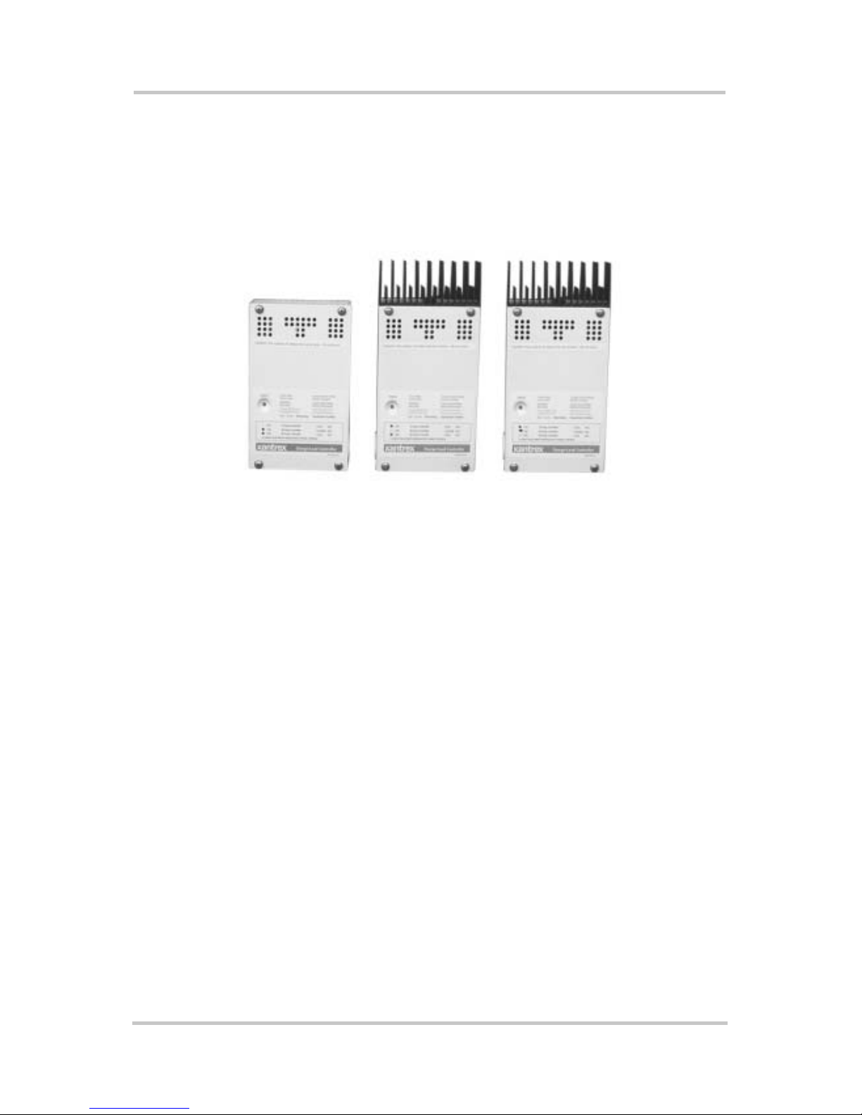
Figure 1-1 C-Series Multifunction DC Charge Controllers - - - - - - 2
Figure 1-2 3-stage Battery Charging Process - - - - - - - - - - - - - - - 5
Figure 1-3 PV Charge Controller - - - - - - - - - - - - - - - - - - - - - - - 7
Figure 1-4 Diversion Controller - - - - - - - - - - - - - - - - - - - - - - - - 9
Figure 1-5 Load Controller - - - - - - - - - - - - - - - - - - - - - - - - - - 11
Figure 1-6 Decal Displaying Load Control Voltage Settings - - - - 12
Figure 1-7 Optional Accessories - CM/R, CM, and BTS- - - - - - - 12
Figure 2-1 Removing the Front Cover - - - - - - - - - - - - - - - - - - - 14
Figure 2-2 C-Series Dimensions and Knockout Locations
(Not to Scale)- - - - - - - - - - - - - - - - - - - - - - - - - - - - 15
Figure 2-3 Mounting the C-Series Multifunction DC Controller - 17
Figure 2-4 Jumper Positions- - - - - - - - - - - - - - - - - - - - - - - - - - 18
Figure 2-5 Circuit Board Co m p one n ts - - - - - - - - - - - - - - - - - - - 1 9
Figure 2-6 Mode of Operation Jumper- - - - - - - - - - - - - - - - - - - 20
Figure 2-7 Voltage Selection Jumper- - - - - - - - - - - - - - - - - - - - 20
Figure 2-8 EQ/LVR Jumper and Reset Switch - - - - - - - - - - - - - 21
Figure 2-9 B ulk and Float Charge Potentiometers (pots)- - - - - - - 22
Figure 2-10 Bulk and Float Charge Settings for Charge/Diversion
Control Mode- - - - - - - - - - - - - - - - - - - - - - - - - - - - 23
Figure 2-11 Potentiometers with Decal for LVR and LVD Settings 24
Figure 2-12 LVR and LVD Settings for Load Control Mode- - - - - 25
Figure 2-13 R46 Resistor Location - - - - - - - - - - - - - - - - - - - - - - 26
Figure 2-14 Voltage Settings with R46 Resistor Clipped - - - - - - - 27
Figure 2-15 Test Points for Adjusting Voltage Using a DVM - - - - 29
Figure 2-16 Manual Equalization Settings - - - - - - - - - - - - - - - - - 30
Figure 2-17 Front Panel LED and Reset Switch Location- - - - - - - 31
Figure 2-18 Auto Equalization Settings - - - - - - - - - - - - - - - - - - - 32
Figure 2-1 9 Terminating the Eq u aliz at ion Ch a rg e - - - - - - - - - - - - 33
Figure 2-20 Grounding the C-Series Chassis - - - - - - - - - - - - - - - 37
Figure 2-21 DC Connection Terminals - - - - - - - - - - - - - - - - - - - 39
xv
Page 18

Figures
Figure 2-22 AWG Wire Gauge Reference Chart - - - - - - - - - - - - - 40
Figure 2-23 PV Charge Control Mode Wiring - - - - - - - - - - - - - - 45
Figure 2-24 Diversion Control Mode Wiring - - - - - - - - - - - - - - - 47
Figure 2-2 5 Load Control Mo de W i rin g - - - - - - - - - - - - - - - - - - 49
Figure 2-2 6 Installing a Dig ital D isp lay- - - - - - - - - - - - - - - - - - - 50
Figure 2-27 Installing the BTS- - - - - - - - - - - - - - - - - - - - - - - - - 51
Figure 2-28 Re-installing the CM Faceplate - - - - - - - - - - - - - - - - 52
Figure 3-1 C -Series Status LED and Reset Button Location - - - - 54
Figure 3-2 C- Ser ie s Fr ont Pan e l Lab el- - - - - - - - - - - - - - - - - - - 55
Figure 3-3 Reset Switch - - - - - - - - - - - - - - - - - - - - - - - - - - - - 61
xvi 975-0004-01-02 Rev D
Page 19

Tables
Table 2-1 Factory Def aul t Se ttin gs for C-Series Con tro l lers- - - - 19
Table 2-2 Variances in Charging Volta ge based on
Battery Temperature - - - - - - - - - - - - - - - - - - - - - - - 35
Table 2-3 Minimum Wire Size - - - - - - - - - - - - - - - - - - - - - - - 41
Table 2-4 One-Way Wire Distance and Wire Size - - - - - - - - - - 43
Table 3-1 Battery Voltage LED Indicators - - - - - - - - - - - - - - - 56
Table 4-1 PV Charge Control Problems - - - - - - - - - - - - - - - - - 64
Table 4-2 Diversion Control Problems - - - - - - - - - - - - - - - - - - 66
Table 4-3 Load Control Problems - - - - - - - - - - - - - - - - - - - - - 68
Table A-1 Electrical Specifications- - - - - - - - - - - - - - - - - - - - - 70
Table A-2 Features and Options Specifications- - - - - - - - - - - - - 71
Table A-3 Environmental Specifications - - - - - - - - - - - - - - - - - 72
Table B-1 Typical Bulk and Float Setpoints for Batteries- - - - - - 79
Table C-1 Power Dissipation- - - - - - - - - - - - - - - - - - - - - - - - - 82
xvii
Page 20

xviii
Page 21

1
Chapter 1 describes features and functions of the
C-Series Multifunction DC Controller.
For information on: See:
“Features” page 2
“Operating Modes” page 3
“Controller Functions” page 7
“Optional Accessories” page 12
Introduction
Page 22
Introduction
Features
The C35/C40/C60 (C-Series) controllers can be used with
12-volt, 24-volt, or 48-volt DC systems (depending upon
model) as Charge Controller or a Load Controller.
C35
Figure 1-1
C40
C-Series Multifunction DC Charge Controllers
C60
Numerous features are provided standard to maximize the
performance of t he system:
• Solid-state Pulse Width Modulated (PWM) charging
process w ith three-stage co ntr o l, temp era ture
compensation, and manual or automatic equalization to
maximize system performance and increase battery life.
• Multi color LED with easy to read mode/status label.
• Electronic overload and short-circuit protection with
automatic and manual rese t capability increases the
reliability of unattended systems by eliminating blown
fuses and tripped cir cuit breakers.
• Adjustment of charge setpoints is provided by rotary
controls (potentiometers) with removable knobs.
Calibrated scales and test points allow precise
adjustments of settings.
• Over-temperature protection for the electronic circuitry
when used in hot environments (over 113 °F/45 °C).
2 975-0004-01-02 Rev D
Page 23

• Indoor-type, powder-coated enclosure, for wall
mounting.
• Conformal-coated circuit boards, plated terminals,
powder-coated metal components, and stainl ess steel
fasteners improves tolerance to hostile environments.
• Meets National Ele ctrical Code (NEC) and other
internat ional co ntr o ller specifi ca tio n s.
• The C35, C40 and C60 models are UL listed to the
U.S. UL Standard 1741 (1st edition), and Canada
(CSA-C22.2 No. 107.1- 95).
• 2-year limite d warranty.
Operating Modes
The DC controller is a criti cal component in any solar, wind
Operating Modes
or hydro power generation system and protects the batteries
from over-discharge and over -charge conditions. The
C-Series has two operating modes (Char ge Contr ol mode and
Load Control mode determined by the Operating mode
jumper (See Figure 2-5). These two different operating
modes allow t he C-Serie s to be inst alled and funct ion as three
different DC controllers.
• Charge Co ntro l Mode
• PV Charge Contro ller - controls charging in PV
installations.
• Diversion Controller – used in PV, wind, or hydro
installations to divert any excess energy to a diversion
load and in the case of a wind or hydro generator, helps
to prevent over-spin damage.
• Load Control Mode
• Load Controller - prevents damage to the battery from
over-discharge during periods of poor charging or
excessiv e loa ds.
975-0004-01-02 Rev D 3
Page 24

Introduction
Important:
than one func tion at the same time. If several functions are
r equir e d in a sys tem, a dedicat ed controller must be used for each
function.
The C-Series controller cannot ope rate in more
Charge Control Mode
In the Charge Control mode, the C-Series controls how the
batteries are charged by the DC source (solar, wind, or
hydro). I t uses a 3-sta ge ch arging pr otocol t o maint ain batte ry
voltage at bulk and/or float levels.
When charging, the C-Series controller monitors the batt eries
and depending on how it is wired will r egulate t he PV current
(as a PV Charge Controller) or divert excess ener gy from PV,
hydro, or wind to a DC load (as a Diversion Controller) and
allows the battery to charge according to user-defined
settings based on the amount of DC power available .
When the C-Series operates in the Charge Control mode, it
provides:
• three-stage charging of batte ry vol tage,
• automatic temperature compensation (if the BTS is used),
and
• automatic or manual equalization charging.
Three-Stage Battery Charging
The three-stage charging process results in faster charging
compared to on-off relay type or constant voltage solid-state
regulators. Faster recharging increases the performance of the
system by storing more of the PV array’s limited output. The
final float volta ge setting reduces battery gassing, minimizes
watering requirements and ensures complete battery
recharging. The C-Series will use this protocol in either PV
Charge Control mode or in Diversion Control mode. It does
not charge the batteries when in Load Control mode. Battery
voltage and curren t vary during the three-stage char ging
process as follows.
4 975-0004-01-02 Rev D
Page 25
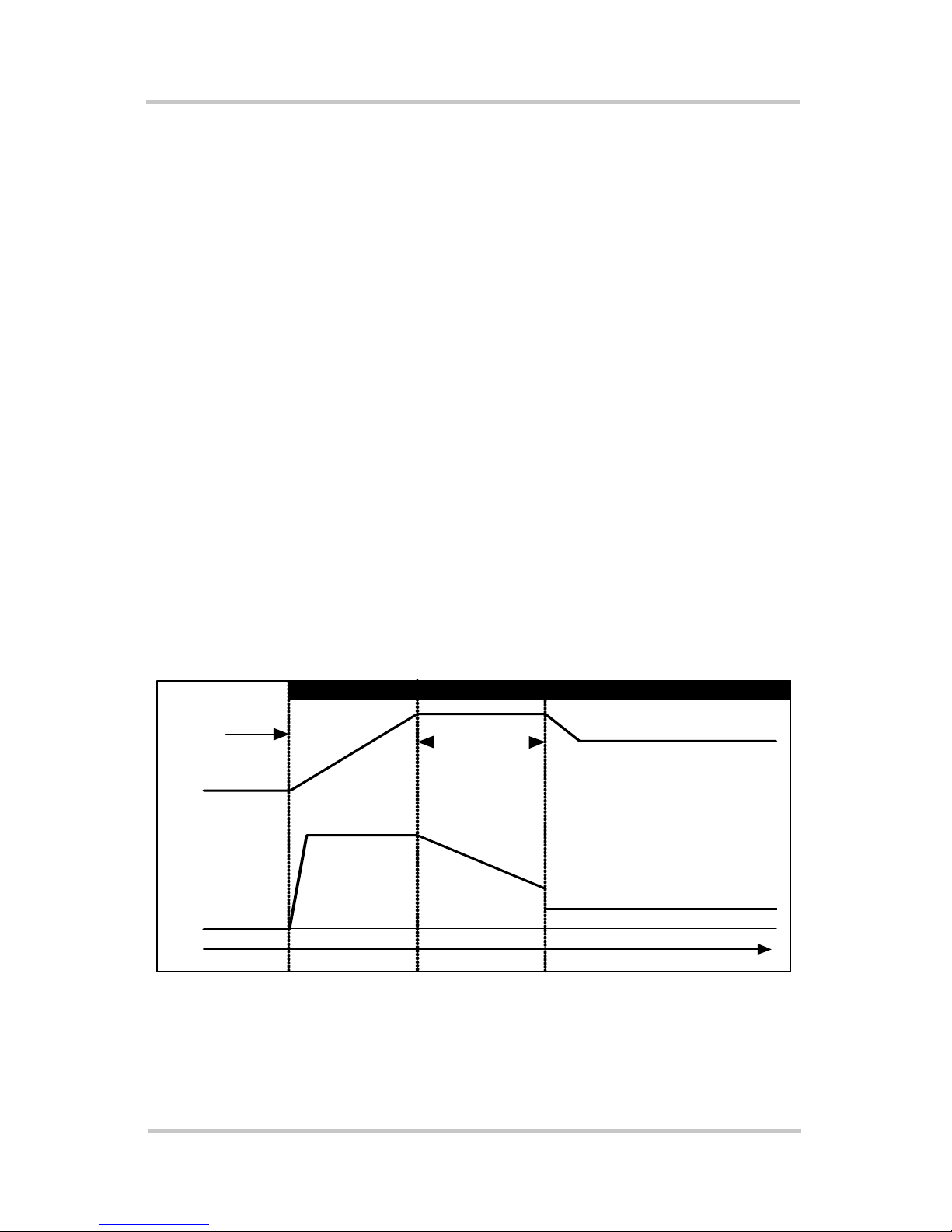
Bulk Stage
During this stage, the batteries are charged at the bulk voltage
setting and maximum current output of the DC source. When
the battery voltage reaches the bulk voltage setting, the
controller activates the next stage (absorption).
Absorption Stage
During this st age, the vo ltage of the ba tter y is held at the bulk
voltage setting until an internal timer has accumulated one
hour. Current gradually declines as the battery capacity is
reached.
Float Stage
During this s tage, the vol tage of t he battery i s he ld at the f loat
voltage setting. Full current can be provided to the loads
connected to the battery during the float stage from the PV
array. When battery voltage drops below the float setting f or
a cumulative perio d of one hour, a new bulk cycle will be
Operating Modes
Charging
Started
DC Voltage
0 volts
DC Current
0 amps
Time
Figure 1-2
triggered.
Bulk Stage
Increasing V oltage Constant Voltage Reduced Voltage
Max Amps
Constant Current Reducing Current Reduced Current
Absorption Stage
Bulk Volts Setting
Absorption Time
3-stage Battery Charging Process
Float Stage
Float Volts Setting
975-0004-01-02 Rev D 5
Page 26

Introduction
Battery Temperature Compensation
The optional Battery Temperature Sensor (BTS)
automatically adjusts the charging process of the C-Series
controller. With t he BT S inst a l l e d , th e C-Series will increase
or decrease the batt ery charging voltage dependi ng on the
temperature of the battery to optimize the charge to the
battery and maintain optimal performance of the battery.
If not using the BTS, the voltage settings for charging will
need to be adjusted based on the tempera ture of the
environment around the batteries and on the type of batteries
being used.
See “Temperature Compensation” on pa ge 33 for information
on how to set the voltage.
Manual or Auto Equalization Charge
The C-Series controller can be used to manually or
automatically provide the battery bank with an equalize
charge. Factory default setting is for MANUAL Equal ization
charging. Be sure to be familiar with all the cautions and
warnings concerning equalization charging batteries or
damage to batteries can occur.
Load Control Mode
In the Load Control mode, the C-Series controls when to
remove a load or loads fro m the system when an
over-discharge or over-load situation occurs. The C-Series
controller uses the user-adjustable setpoints to determine
when to connect or reconnect loa ds depending on battery
voltage. A load controller prevents damage to the battery
from over-discharge during periods of poor weather or
excessiv e loa ds. The u nit doe s no t charg e the bat teri es whe n
in this function.
6 975-0004-01-02 Rev D
Page 27
Controller Functions
The C-Series can be configured to function as three different
controllers:
• PV Charge Controller (Charge Control mode)
• Diversion Controller (Charge Control mode)
• Load Controller (Load Control mode)
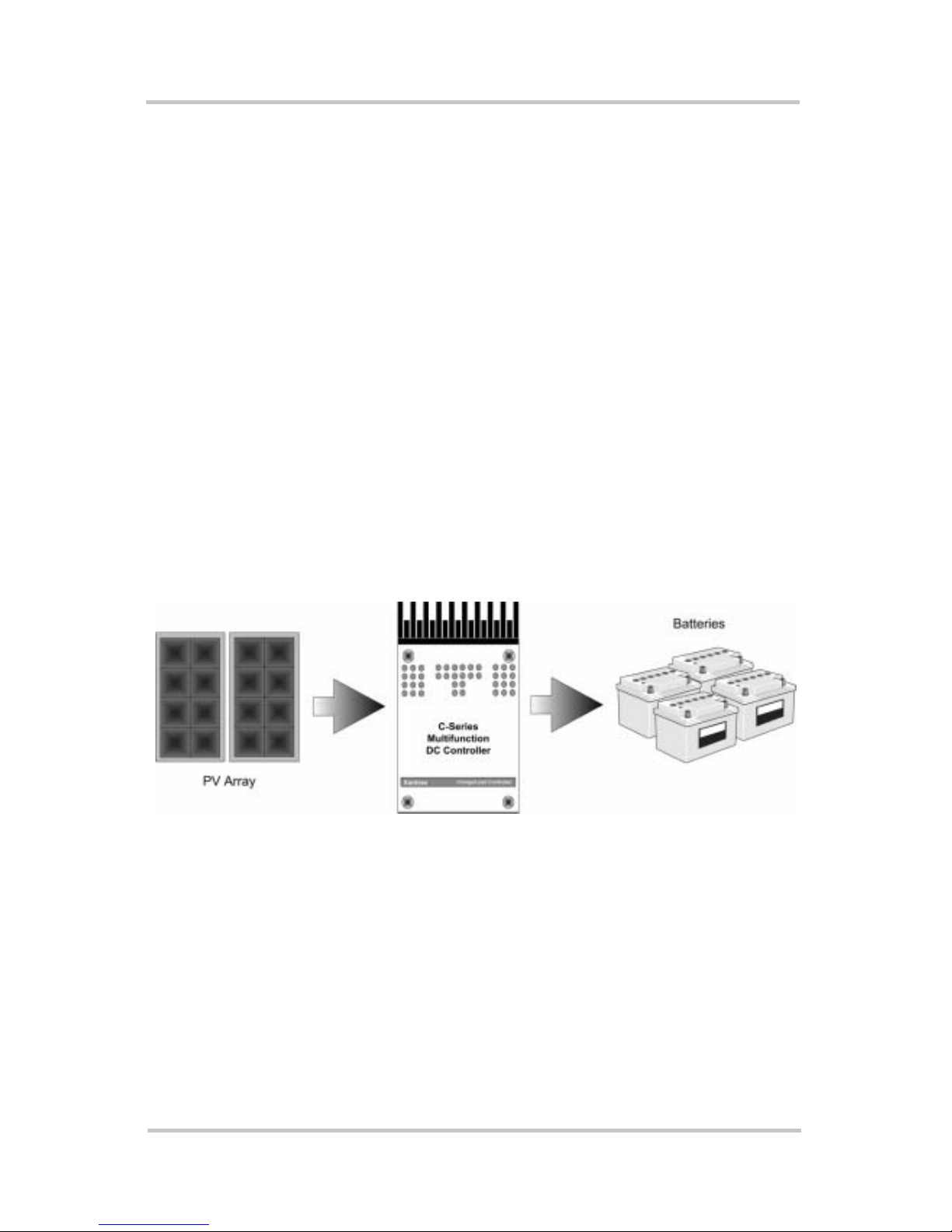
Photovoltaic Charge Controller
The C-Series controller can operate as a Photovoltaic Charge
Controller, also called a “series re gulator”. Depending on the
model, the controller can regulate up to 60 amps of
continuous photovoltaic (PV) array current at 12 or 24 volts
(C60 or C35 m odels) , or 12-, 24- or 48-volts DC (C40 model)
Controller Functions
Figure 1-3
for charging batteries. This rating includes the NEC required
derating.
PV Charge Controller
If the PV array’s output increases above the rated amp level
due to reflection or “edge of cloud effect,” the controller will
continue to operate until the heatsink reaches a maximum
safe operating te mperature. This will take several minutes to
occur, depending upon the ambient temperature involved.
When the heat si n k reach es the max imu m saf e temp era ture,
the controller will reduce the current, cooling the transistors
and the heatsink.
975-0004-01-02 Rev D 7
Page 28

Introduction
If the current from the PV array reaches 85 amps, the
controller will turn off to protect the circuitry. In the event of
a shutdown, the controller automatically resets itself after
10 m inutes (if overcurrent condition is no longer present).
See “Operati ng Mode Jumper ” on page 20 for information on
configuring this function.
Automatic PV Array Night Disconnect
When using PV Charge Control mode, the PV array is
automatically disconnected from the battery at night to
prevent reverse leakage of power . This eliminates the need
for a blocking diode between the battery and the PV array. If
thin-film or amorph ous solar modules are being used, diodes
may still be required to prevent damage from partial shading
conditions.
Check the documentation pr ovided with the PV modules.
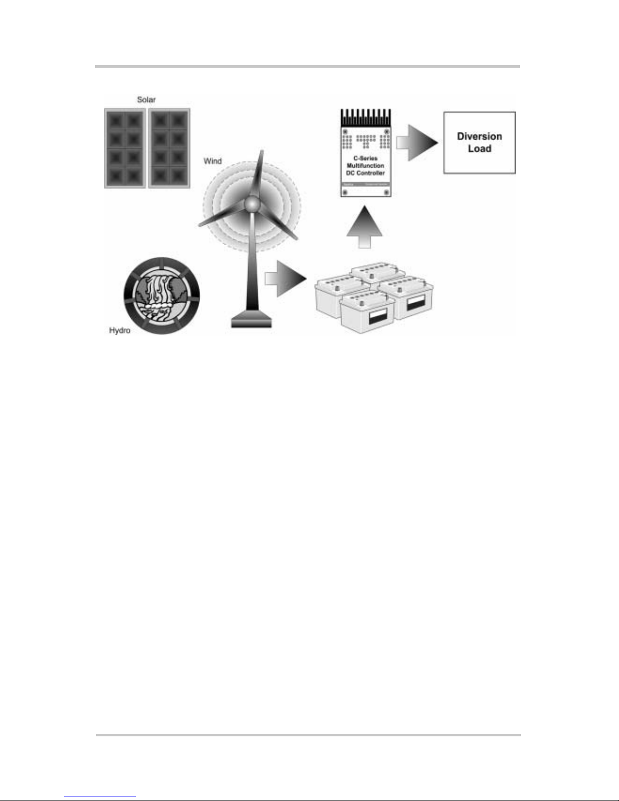
Diversion Controller
The C-Series controller can operat e as a Diversion Controll er,
also called a shunt reg ulator , to manage battery char ging from
alternative energy sources such as PV, wind or hydroelectric
generators. A diversion controller monitors battery voltage
and, when the voltage exceeds the settings for your charge
stage (whether bulk or float), the power is diverted from the
source (solar, wind, or hydro generator) to a “dump” load
which will dissipate the excess power into heat.
When used for this purpose, the C-Series controller varies an
amount of battery voltage to a “dump load” in order to
redirect the exce ss power generated from over-cha rging the
batteries. This allows the charging source to remain under
constant loa d to prev ent an over -speed c ondit ion which could
occur if the charging source is suddenly disconnected from
the battery–a s series regulators do.
Consult your dealer for recommendations on diversion load
type and regulator siz e.
8 975-0004-01-02 Rev D
Page 29
Controller Functions
Figure 1-4
Diversion Controller
Diversion Loads
Diversion con trol requ ires a se parate “ dump” load t o regul ate
the battery. This load must be able to abso rb more po wer than
the charging source is able to produce at its peak output, or
the DC voltage will become unregula ted. The dump load
must be available for the diversion of power at all times.
Resistive-type heating elements are the best diversion loads.
Special direct-current w at er heat in g elem en t s are av ai lab le .
Light bulbs and motors are not rec ommended as diversion
loads because they are unreliable. A diversio n load that draws
about 25% more current than the char ging source’ s maximum
output capability is usually suitabl e for use with the C-Series
controller.
See Appendix C, “Diversion Loads” for additional
information on types of diversion loads.
See “Operating Mode Jumper” on page 20 for instructions on
enabling this mode.
975-0004-01-02 Rev D 9
Page 30
Introduction
Important:
may be necessary to install diodes to prevent night-time
back-feed. If in doubt, contact or consult with your local
renewable energy expert.
Important:
to pre v en t back fe ed .
If PV arrays are used with diversion control, it
If using multiple RE sources, use diodes/isolatio n
CAUTION: Damage to Batteries
Current dra w of the di ver sion l oad is very import ant. Pr oble ms may
arise from operating with a load that is too s mall or too large. A
diversion load that is too sma ll will not be able to absorb all the
excess power fr o m the current source once the batteri es are full
allowing ba tteries to overcharge.
Diversion loads in excess of the controller ’s rating are capable of
absorbing more power than the C-Series control ler is designed to
handle, re sult ing in an ove r -curr ent shut down. Dur ing thi s ti me, the
unit will not regulate electrical flow in the system and battery
damage may result.
Load Controller
The C-Series controller can opera te as a Low Vol ta ge
Disconnect (LVD) for DC loads to prevent over-discharge to
batteries during periods of poor charging or exces sive loads.
The C-Series contro ller uses the user-adjusta ble setpoints to
determine when to discon nect or reconnect loads depending
on battery voltage .
When used as a DC load controller, the settings of the LVR
and LVD are controlled by two rotary potentiometers (also
called pots) on the circuit board.
The scale on the adjustment potentiometers differ from the
scale used for other fun ctions. A decal with the appropriate
adjustment scale is included with the C-Series. To apply the
decal, gently pull off the knobs of the potentiometers and
place this decal on the cir cuit board. After the decal is in
place, repl ace the knobs. The EQ jumper determines manual
10 975-0004-01-02 Rev D
Page 31

or automatic reconne ct when the C-Series i s used as a load
controller. Do not use this decal if using the C-Series
controller as a PV Charge Controller or Diversion Control ler.
Low Voltage Disconnect
When configured as a l oad controller, the C-Series controller
will disc onnect the load fr om the batter ies whe n it reaches the
LVD setting. There will be a 6-minute delay after the voltage
drops below the Low Voltage Disconnect (LVD) setting
before the contro ller actually disconnects the load.
Low Voltage Reconnect
It can also provi de automatic reconnection of the loads at the
LVR (Low Voltage Reconnect) setting. Reconnection of the
load is allowed once the batt ery voltage has exceeded the
Low Voltage Reconnect (LVR) setting.
Controller Functions
Figure 1-5
Loads are either automatically or manually reconnected when
battery voltage exceeds the Low Voltage Reconnect (LVR)
setting for 6 minutes.
See “Operating Mode Jumper” on page 20 for instructions on
enabling this mode.
Load Controller
Important:
• Do not temperature-compensate these settings.
• Do not insta ll the optional ba ttery temperatur e
compensation sensor.
When using the DC Load Control mode:
975-0004-01-02 Rev D 11
Page 32

Introduction
A
p
L
S
Potentiometer knobs
ttach decal over
otentiometers for
oad Control
ettings
Figure 1-6
Decal Displaying Load Control Voltage Settings
Optional Accessories
The follow accessories can be purchased for use with the
C-Series Multifunction DC Controller:
• Display M et ers : The CM faceplate or CM/R remote
display provide a digital display for monitoring the
C-Series controller’s operation. The CM faceplate
attaches directly to the front of the C-Series controller.
The CM/R is intended for remote appli cations. These
meters provide a digit al display of current, voltage,
amperage, and amp hours.
• Battery Temperature Sensor (BTS): The BTS is
installed on the side of the battery and attaches to the
circuit board inside the C-Series controller. It provi d es
accurate sensi ng of the battery temperature and uses this
reading to control charging. Using this accessory can
extend battery life and improve overall charging.
Figure 1-7
12 975-0004-01-02 Rev D
BTS
CM/R
CM
Optional Accessories - CM/R, CM, and BTS
Page 33

2
Chapter 2 contains information and procedures to install
C-Series Multifunction DC Controller.
For information on: See:
“Pre-Installation” page 14
“Mounting the Controller” page 16
“Configuring the C-Series Control ler” page 18
“Adjusting the C-Series Voltage Settings” page 22
“Grounding” page 37
Installation
“Wiring” page 38
“Installing Optional Accessories” page 50
“Inst alling the Battery Temperature Sensor” page 51
Page 34

Installation
Pre-Installation
The instru ction s that fo llow are ap pl ic abl e to the typic al
installation. For special applications, consult a qualified
electrician or your Xantrex Certified Dealer. Installation
procedures will vary according to your s peci fi c app lic at ion.
Important:
standards . Installations of this equipment should only be
performed by skilled personnel such as qualified electricians and
Certi fi e d Renewabl e En er gy (RE) Syst em Instal lers. Fo r a li st of
Xantrex Certified RE dealers, please visit our website at
www.XantrexREdealers.com.
Installations should meet all local codes and
Removing the Top Cover
Access the inside of the contr oller by removing the four
phillips screws (#10-32 x 3/8" SMS screws) on the front
cover of the unit.
Remove these
phillips screws (x4)
from the front cover
to access the inside
of the controller.
Figure 2-1
Removing Knockouts
Six dual-knockouts are provided to accommodate the
necessary wiring of the C-Series controller. Be sure to
remove any metal shavings created by removing the
14 975-0004-01-02 Rev D
Removing the Front Cover
Page 35

Pre-Installation
)
knockouts before making any wiring connections. It is also
recommended to use bushings or conduits to protect the
wiring from damage from rough edges in the knockout holes.
Heatsink not
included on C35
8"
(203 mm)
Keyhole Slots for
mounting
2"
(51 mm)
1
8"
(203 mm
Additional Mounting
Holes (x4)
6 7/8"
(174 mm)
Figure 2-2
2
2 ¼”
(64 mm)
This distance varies per model:
1
Side View
Dual-Knockouts
Rear View
3 5/8”
(93 mm)
5”
(127 mm)
C35 = 3/8"
C40, C60 = 5/8"
½ and ¾"
¾ and 1"
2
Dual-Knockouts (x4)
(1 on each side and 2 on the bott om of chassis)
C-Series Dimensions and Knockout Locations (Not to Scale)
975-0004-01-02 Rev D 15
Page 36

Installation
Mounting the Controller
The C-Series controller is designed for indoor mounting.
Care should be taken in selecting a location and when
mounting the enclosure. Avoid mounting it in direct sunlight
to prevent heating of the enclosure. The enclosure should be
mounted vertically on a wall.
In outdoor installations, the C-Series controller must be
installed in a rai nproof enclosure to eliminate exposu re to
rain, mist or water-spray.
CAUTION: Damage to C-Series Controller
Install the C-Series control le r in a dry, protecte d location away
from sources of high te m perature, moisture , and vibration.
Exposure to s altwater is particularly destructive. Corrosion is not
covered by the warranty.
To mount the C-Series controller:
1. Remove the facepla te on the controller.
2. Place the controller on the desired mounting sur fac e and
mark the location of the keyho le slots on the wall.
3. Move the controller out of the way, and secure two
mounting screws in the locations marked. Leave the
screw heads backed out approximately ¼ inch (6 mm)
or less.
4. Place the controller onto the screws and pul l it down into
the keyhole slots.
5. Then insert the two more screws in two of the four
additional mounting holes provided to secure the
enclosu re onto the w all .
6. Provide either strain-reli ef cl amps or conduit to prevent
damage to the circuit board and terminal block from
pulling on the wires.
16 975-0004-01-02 Rev D
Page 37

WARNING: Explosion/Corrosion Hazard
Do no t lo c at e th e C-Series controller in a se aled compartm ent with
the batteries. Batteri es can vent hydrogen-sulfide gas, which is
corrosive to elect roni c equipme nt. Batte ries also genera te hydro gen
and oxygen gas tha t ca n explode when exposed to a spark.
If using “sealed” batteries, the controller can be mounted in
the same enclosure as long as it is adequa tely ventilated.
Place keyhol e slot s on the ba ck of the
controller over the mounting screws.
Approximately
¼inch
Pre-Installation
Mounting Surface
Figure 2-3
Mounting
Screws
Secure i n place with
2 more screws.
Mounting the C-Series Multifunction DC Controller
975-0004-01-02 Rev D 17
Page 38

Installation
Configuring the C-Series Controller
Before making any wiring conne ctions to the C-Series
controller, it must be configured for the desired mode of
operation. The following sections describe the how to
configure the unit for the desired application and function.
Jumper Settings
Three sets of jump ers are lo cat ed on t he righ t side of th e
controller’s circuit board. These jumpers control
equalization, low voltage reconnect, battery voltage, and
operating modes. They must be installed correctly for the unit
to operate to its maximum potential.
To enable a selection, carefully slide the jumper over the top
of both pins. This is call ed ins talling the jumper.
To disa ble a selecti on, carefully slide the jumper over only
one of the pins. This is called removing the jumper.
Jumper Removed
(Jumper is only on one pin)
Jumper
Jumper Installed
(Jumper is on both pins)
Figure 2-4
Jumper Positions
The factory default settings are shown in Table 2-1, “Factory
Default Settings for C-Series Controllers ” on page 19.
Important:
jumpers so as not to bend the pins.
18 975-0004-01-02 Rev D
Use extreme caution whe n installing an d removing
Page 39

Configuring the C-Series Controller
r
Table 2-1
Factory Default Settings for C-Series Controllers
Setting C35, C40 and C60
Battery Voltage 12 volts DC
Equalize /LVR Manual Equ alization
Operating Mode Charge Control
NiCad Setting
Selection R46
Resistor
Load Control
Decal
EQ/LVR
Jumper
Operating
Mode Jumper
Rese t Swit ch
Potentiometers
Voltage Jumpe
Battery
Temperature
Sensor Port
DC Terminal Connectors
CM or CM/R Port
Note: This photograph shows the Load Control Voltage decal installed on th e
circuit board over the potentiometers.
Figure 2-5
Circuit Board Components
975-0004-01-02 Rev D 19
Page 40

Installation
Operating Mode Jumper
This jumper determines the operating mode. Place the jumper
over the pins that correspond to the desired mode.
• Charge Control (PV Charge Controller or Diversi on
Controller)
• Load Control (Load Controller)
Factory defaul t setting is Charge Control mode.
Charge/Load
Control
Jumper
Charge Control Mode
Load Control Mode
Figure 2-6
Voltage Jumper
The voltage jumper determines the voltage of the syste m that
the controller will be used with. To set the voltage, place the
jumper over the two pins adjacent to the legend for the
voltage of your system: 12, 24, 48. Factory se tting is 12 volts
for the C35, C40, and C60.
C40 Models
C35 and C60
Models
Mode of Operation Jumper
12 Volt Positio n
24 Volt Positio n
48 Volt Positio n
12 Volt Positio n
24 Volt Positio n
Figure 2-7
20 975-0004-01-02 Rev D
Voltage Selection Jumper
Page 41

Configuring the C-Series Controller
Automatic/Manual Battery Equalization (EQ) and Low Voltage
Reconnect (LVR) Jumper
Depending on the mode of operation chosen, this jumper
enables:
• automatic or manual battery equalization
(Charge Control mode), or
• automatic or manual reconnect in the event of low
voltage event (Load Control mode).
When A
UTO is enabled in the Charge Control mode, the unit
will perform an equaliz ation charge every 30 days. This can
be done manually by using Reset Switch on the side of the
controller chassis .
When AUTO is enabled in Load Control mode, the unit will
reconnect automatically when voltage at the BATTERY
POSITIVE terminal exceeds the L VR setting. This can also be
done manually by using Reset Switc h on the side of the
controller chassis .
The factory default se tting is M
ANUAL EQUALIZATION
(Charge Control mode).
Place the jumper over the pins for the desired selection.
EQ/LVR Jumper
Figure 2-8
See “Error Mode Indica tion (Orange)” on page 59 for
instructions on how to use the Reset Switch in relation to this
function.
975-0004-01-02 Rev D 21
MANUAL
AUTO
EQ/LVR Jumper and Reset Switch
Page 42

Installation
Adjusting the C-Series Voltage Settings
The charging voltage setpoints and voltage reconnect/
disconnect setting of the controller are adjustable using two
rotary potentiom eter controls. The knobs are removable to
reduce the likelihood of accidental mis-adjustment if
bumped.
Calibrated scales, shown as scale marks, are provided to
allow setting of the control without requiring the use of a
digital voltmeter .
For more information regarding bulk and float charging
voltages, se e “Three -Stage Battery Charging” on page 4.
Setting indicator
Potentiometers
Figure 2-9
Scale Marks
Bulk and Float Charge Potentiometers (pots)
Setting Voltage Parameters for Charge Control Mode
To set the controller to a specific voltage, point the setting
indicator at the scale mark representing the desired voltage.
The potentiomete r scale for BULK charge voltage is
calibrated as follows:
• 12-volt system: 13.0 to 15.0 volts
in increments of 0.2 volts,
• 24-volt system: 26.0 to 30.0 volts
in increments of 0.4 volts,
• 48-volt system: 52.0 to 60.0 volts
in increments of 0.8 volts.
22 975-0004-01-02 Rev D
Page 43

Adjusting the C-Series Voltage Settings
1
)
)
1
2
)
)
2
5
)
)
5
For FLOAT charge voltage, the potentiometer scale is
calibrated follows:
• 12-volt system: 12.5 to 14.5 volts
in increments of 0.2 volts,
• 24-volt system: 25.0 to 29.0 volts
in increments of 0.4 volts, and
• 48-volt system: 50.0 to 58.0 volts
in increments of 0.8 volts.
14.8
13.2
14.3
12.7
15.0
BULK (C HG
13.0
14.5
FLOAT (CHG
12.5
28.8
28.4
8.0
27.6
27.2
27.8
27.4
7.0
26.6
26.2
14.6
14.4
14.2
4.0
13.8
13.6
13.4
14.1
13.9
13.7
3.5
13.3
13.1
12.9
12-Volt System Sett ings
59.2
52.8
57.2
50.8
60.0
BULK (CHG
52.0
58.0
FLOAT (CHG
50.0
58.4
57.6
56.8
6.0
55.2
54.4
53.6
56.4
55.6
54.8
4.0
53.2
52.4
51.6
29.6
29.2
30.0
BULK (CHG
26.8
28.2
26.4
28.6
26.0
29.0
FLOAT (CHG
25.8
25.4
25.0
24-Volt System Sett ings
48-Volt System Sett ings (C40 only)
Figure 2-10
Bulk and Float Charge Settings for Charge/Diversion
Control Mode
975-0004-01-02 Rev D 23
Page 44

Installation
Setting Voltage Parameters for Load Control Mode
To change the Low Voltage Disconnect (LVD) and Low
Voltage Reconne ct (LVR) settings, use the same BULK and
FLOAT potentiometers. However, when the C-Series
controller is use d for DC Load Control, the potentiometer’s
scale calibration is altered from what is printed on the circuit
board.
Figure 2-11
BULK Setting
Potentiometer
FLOAT Setting
Potentiometer
LVR Setting
LVD Setting
Potentiometers with Decal for LVR and LVD Settings
A decal is provided with the C-Series with the proper scale
calibrations for the Load Control mode. The BULK
potentio me te r beco m es the Low Vol ta ge Reconnect (LVR),
and the FLOAT potentiometer becomes the Low Voltage
Disconnect (LVD).
Place the sticke r provided over the potent iometers. The knobs
may have to be removed for sticker place ment, then
reinstalled. The sticker is packed inside the C-Series
controller ( bottom of unit). If the decal is lost or unavailable,
you can recalculate the appropriate voltage settings as
follows:
The scale for the Low Voltage Reconnect setting is calibrated
as follows:
• 12-volt system: 12.0 to 14.0 volts
in increments of 0.2 volts,
• 24-volt system: 24.0 to 28.0 volts
in increments of 0.4 volts,
• 48-volt system: 48.0 to 56.0 volts
in increments of 0.8 volts.
24 975-0004-01-02 Rev D
Page 45

Adjusting the C-Series Voltage Settings
1
1
)
E
2
2
)
E
5
4
)
E
The scale for the Low Voltage Disconnect setting is
calibrated as follows:
• 12-volt system: 10.5 to 12.5 volts
in increments of 0.2 volts,
• 24-volt system: 21.0 to 25.0 volts
in increments of 0.4 volts, and
• 48-volt system: 42.0 to 50.0 volts
in increments of 0.8 volts.
27.6
24.4
24.6
21.4
28.0
L
24.0
25.0
21.0
13.2
3.0
12.8
11.7
1.5
11.3
13.4
12.6
11.9
11.1
13.6
12.4
12.1
10.9
13.8
12.2
12.3
10.7
14.0
12.0
12.5
10.5
.V.R (LOAD)
L
L
OW VOLTAGE
R
ECONNECT
L.V.D
(LOAD
L
OW VOLTAG
D
ISCONNECT
27.2
26.8
26.4
6.0
25.6
25.2
24.8
24.2
23.8
23.4
3.0
22.6
22.2
21.8
12-Volt System Sett ings 24-Volt System Sett ings
L.V.R
(LOAD)
OW VOLTAGE
R
ECONNECT
L.V.D
(LOAD
L
OW VOLTAG
D
ISCONNECT
55.2
48.8
49.2
42.8
56.0
48.0
50.0
42.0
L.V.R
(LOAD)
L
OW VOLTAGE
R
ECONNECT
L.V.D
(LOAD
L
OW VOLTAG
D
ISCONNECT
54.4
53.6
52.8
2.0
51.2
50.4
49.6
48.4
47.6
46.8
6.0
45.2
44.4
43.6
48-Volt System Settings (C40 only)
Figure 2-12
975-0004-01-02 Rev D 25
LVR and LVD Settings for Load Control Mode
Page 46

Installation
Setting Voltage Parameters Diversion Control Mode
When the C-Series controller is configured for Diversion
Control mode, you can set the voltage at which the unit
begins diverting current to a diversion load (high voltage
diversion). Use the Charge Control scale for setting this
value.
See Figure 2-10 on page 23 for Charge Control scale settings.
The unit will continue diverting excess current to the
diversion load until the source voltage falls to or below the
BULK setting. After one hour at the BULK setting, the unit
will reduce the battery charging voltage to the FLOAT
voltage setting. This will usually result in mor e current being
diverted to the diversion load.
Setting Voltage Parameters for Alkaline Batteries
If using NiCad or NiFe batteries, the required charging
voltages may be higher than the designed settings of the
C-Series controller. Charging voltages can be augmented a
little, if req uired. This can be accomplished by clipping the
wire connecting the R46 Resistor to the circuit board. This
augmentation will raise the designed charg e paramete rs by
2 volts for 12-volt systems, 4 volts for 24-volt systems and
8 volts for 48-volt systems.
See Figure 2-14 for the augmented voltage settings.
If using NiCad batt eries,
clip this wire here. Do NOT
remove the R46 Resistor.
Figure 2-13
26 975-0004-01-02 Rev D
R46 Resistor Location
R46 Resistor
Circuit Board
Page 47

1
)
16.2
)
1
3
)
)
3
6
)
)
6
6.0
15.8
15.7
5.5
15.3
16.4
15.6
15.9
15.1
16.6
15.4
16.1
14.9
16.8
15.2
16.3
14.7
17.0
BULK (CHG
15.0
16.5
FLOAT (CHG
14.5
Adjusting the C-Series Voltage Settings
33.6
30.4
32.6
29.4
34.0
BULK (CHG
30.0
33.0
FLOA T (CHG
29.0
32.4
2.0
31.6
31.4
1.0
30.6
32.8
31.2
31.8
30.2
33.2
30.8
32.2
29.8
12-Volt System Settings
Figure 2-14
24-Volt System Sett ings
67.2
60.8
65.2
58.8
68.0
BULK (CHG
60.0
66.0
FLOAT (CHG
58.0
64.8
4.0
63.2
62.8
2.0
61.2
65.6
62.4
63.6
60.4
66.4
61.6
64.4
59.6
48-Volt System Settings (C40 onl y)
Voltage Settings with R46 Resistor Clipped
CAUTION: Damage to Batteries
It is not re co mmended to al lo w an eq ualiz e charge to o ccur if th e
975-0004-01-02 Rev D 27
R46 Resistor is clipped. Higher charging voltages may damage the
batteri es . Make sure the EQ/LVR jumper is on the MANUAL
Setting.
Page 48

Installation
Using a Digital Voltmeter to Adjust Voltage Settings
A digital DC vol tmete r (DVM) can be used t o provide a more
accurate setting of voltage parameters. Test points are
provided at the mid-range on the scales for this purpose.
The potentiometers are equipped with removable knobs to
prevent accidental mis-adjustments. If the knobs are missing,
a 5/64" hex-head drive r can be used to adjust the settings.
To test and adjust the voltage setting using a DVM:
1. Point the potentiometers to the mid-range position.
2. Connect a digital voltmeter from one of the common
negative termina ls on the circuit board and the small test
point located to the le ft of each potentiometer at the
nine o’clock position. See Figure 2-15.
The test point provides a reading from 0 to 2 volts.
(Multiply this value by “2” for 24-volt system and by
“4” for 48-volt system.)
3. Add the value obtained in step 2 above to the lower val ue
of the adjustment range/voltage scale being used.
For exampl e for a 12-vo lt system :
To set the BULK voltage to 14.4 volts:
1. Point the BULK potentiometer to the mid-range position.
2. Adjust the potentiometer until the DVM displays
1.4 volts (13.0 V + 1.4 V = 14.4 V).
For exampl e for a 24-vo lt system :
To set BULK voltage to 28.2 volts:
1. Point the BULK potentiometer to the mid-range position.
2. Adjust the potentiometer until the DVM displays
1.1 volts (1.1 x 2 [24 volt] = 2.2 + 26.0 = 28.2).
28 975-0004-01-02 Rev D
Page 49

For exampl e for a 48-vo lt system :
To set BULK voltage to 56.4 volts:
1. Point the BULK potentiometer to the mid-range position.
2. Adjust the potentiometer until the DVM displays
1.1 volts (1.1 x 4 [48 volt] = 4.4 + 52.0 = 56.4).
TEST POINTS for DVM
(center legs of
potentiometer)
Adjusting the C-Series Voltage Settings
Battery Common Negat ive
Terminals
Figure 2-15
Test Points for Adjusting Voltage Using a DVM
975-0004-01-02 Rev D 29
Page 50

Installation
Equalization Charging
CAUTION: Damage to Batteries
:
Equalization should be done for standard electrolyte, vented
batteries only. Sealed, GEL cell, or NiCad batteries should not be
equalize-charged . Cons ult your battery supplier for details on
equalize-charging for the battery type in your system.
The C-Series offers either manual or automatic triggering of
the equalization charging process . Equa lization charging is
the deliberate process of charging a battery (or battery bank)
at a high voltage for a set period of ti me to remix the
electrolyte and destratify the internal plates. Equalize
chargi ng helps to remove sulfate bui ldup on the batte ry plate s
and balances the char ge of individual cells.
Equalization charging holds the voltage above the BULK
setting for 2 hours by 1 volt for 12-vo lt systems, 2 volts for
24-volt systems, and 4 volts for 48-volt systems.
The default setti ng for this feature is M
ANUAL. Automatic
equalization is enabled by moving the jumper located on the
right side of the circuit board above the reset switch to the
appropriate A
Figure 2-16
UTO pin set. See Figure 2-18
Manual Equalize
(Default Setting)
Auto Equalize
Manual Equalization Settings
When autom at i c has bee n select ed, an equ al izat i on charge
will occur every 30 days.
During the equalization process, the status LED indicate s
equalization by alternately blinking green and red.
Important:
power is removed from the controller.
30 975-0004-01-02 Rev D
The auto equali zation period is rese t when DC
Page 51

Manual Equalization
F
(
d
Manual equaliza tion of the battery can be enabled by pressing
the Reset Switch on the right side of the C-Series until the
status LED indicator begins to alternate between red and
green. This could ta ke about 10 seconds.
ront Panel LED
flashes red/green
uring equalization)
Equalization Charging
Reset
Switch
Access
Figure 2-17
Front Panel LED and Reset Switch Location
The equalizat ion process will conti nue until th e batteries have
been held at or above the bulk setti ng for two hours of
accumulated time. Once the battery voltage has been at or
above the bulk setting for a cumulative period of two hours,
the C-Series will return to the float stage of the charging
process.
During the equalization process, the status LED will alternate
between red and green and will not provide any other
mode/status indi cation. Lar ge batte ry b anks may need s evera l
equalization cycles to fully stir the electrolyte and charge the
cells. These cycl es should follow one another until the battery
voltage reaches the upper limit for the full two hours.
975-0004-01-02 Rev D 31
Page 52

Installation
Automatic Equalization
The C-Series controller can automatically tr igger an
equalization charge every 30 days. The status LED will
indicate that the equalization process is occurring.
The equalizati on process will continue until the volta ge has
been held above the bulk setting for a cumulative period of
two hours. This might take several days on larger systems
with big batteries a nd small PV arrays. The battery voltage
only needs to exceed the bulk setting for the timer to start
counting–the voltage may not reach the equalization voltage
setting.
To enable aut o ma tic eq ual i zati on , the jum p er located on t he
right side of the circ uit board must be moved to the A
setting. The default se tting of the C-Series con tro ller is for
manual equalization. To disable the automatic equalization
system, move the equalize jumper to MANUAL.
UTO
Manual Equalize
Auto Equalize
Figure 2-18
Auto Equalization Settings
Once a manual equalization ha s been triggered, the 30-day
period to the next a utomatic equa liza tion will be restar ted. To
prevent automatic equalization, move the equalize jumper to
the manual position.
Important:
It is not recommended to use the Equalization
feature if the R46 Resistor is clipped.
32 975-0004-01-02 Rev D
Page 53

Temperature Compensation
Terminating the Equalization Process
T o stop the equaliz ation process, press the reset switch on the
right side of the unit until the status LED stops alternating
between red and green.
If the equalizat ion process was shorter than one hour, the
controller will continue with a bulk charge cycl e and then
hold the battery at the bulk se tting for one hour (the
absorption stage) before returning to the float setting.
Front Panel LED
(flashes red/green
during equalization)
Figure 2-19
Terminating the Equalization Charge
Temperature Compensation
Important:
• Do NOT compensate the settings.
• Do not instal l the Battery Temperat ure Sensor .
For optimal battery charging, the Bulk and Float char ge rates
should be adjusted according to the temperature of the
battery. When battery charging voltages are compensated
based on tempera ture, th e char ge vol tage wi ll var y depending
If using the C-Series as a DC Load Contr o ller:
Press Reset
Switch until LED
stops alternating
between red and
green
on the temperature around the batteries.
975-0004-01-02 Rev D 33
Page 54

Installation
Temperature Compensation Based on Battery Type
The C-Series controller uses the battery type to determine the
temperature compensated voltage settings. The temperature
compensated charging voltage is normally based on a Lead –
Acid types of battery.
If using Alkaline-type batteries, the R46 resistor on the
circuit board inside the controller will have been clipp ed as
shown in “ Sett ing Voltage Parameters for Alka line Batter ies”
on page 26. If the R46 resistor is cut, the temperature
compensation charging voltage will be based on
Alkaline-type batteries.
See the battery type below to determine the temperature
compensation v alue change per temp erature or refer to the
temperat u re com p en sat ion calcu l ati o ns for a Le ad-A ci d typ e
battery as show in Table 2-2.
• Lead-Acid T ype Batteries:
5 mV per cell per degree Celsius
• Alkalin e -Type Batteries (Ni C ad o r N iFe ):
2 mV per cell per degree Celsius
Table 2-2 describes approximately how much the voltage
may vary depending on the temperatur e of the batteries.
Automatic Battery Temperature Compensation
Temperat u re compensat ion can b e accomplished
automatically by using a Battery Temperature Sensor (BTS).
The sensor atta ches directly to the side of one of the ba tteries
in the bank and provides precise battery temperature
information.
See “Instal ling the Battery Temperature Sensor” on page 51
for detailed instructions on how and where to install the BTS.
If a BTS is installed, the charge controlling process will be
automatically adjusted for the battery temperature. When
using a BTS, set the Bulk and Float voltage for a battery at
normal room temperature for 77 °F (25 °C).
34 975-0004-01-02 Rev D
Page 55

Temperature Compensation
Table 2-2
Variances in Charging Voltage based on Battery Temperature
Temperature
(around the BTS) 12-volt units 24-volt units 48-volt units
Celsius Fahrenheit
Lead
Acid
(6 cells)
NiCad
(10 cells)
Lead
Acid
(12 cells)
NiCad
(20 cells)
Lead
Acid
(24 cells)
NiCad
(40 cells)
60 140 -1.05 -0.70 -2.10 -1.40 -4.20 -2.80
55 131 -0.90 -0.60 -1.80 -1.20 -3.60 -2.40
50 122 -0.75 -0.50 -1.50 -1.00 -3.00 -2.00
45 113 -0.60 -0.40 -1.20 -0.80 -2.40 -1.60
40 104 -0.45 -0.30 -0.90 -0.60 -1.80 -1.20
35 95 -0.30 -0.20 -0.60 -0.40 -1.20 -0.80
30 86 -0.15 -0.10 -0.30 -0.20 -0.60 -0.40
25 77 0.00 0.00 0.00 0.00 0.00 0.00
20 68 0.15 0.10 0.30 0.20 0.60 0.40
15 59 0.30 0.20 0.60 0.40 1.20 0.80
10 50 0.45 0.30 0.90 0.60 1.80 1.20
5 41 0.60 0.40 1.20 0.80 2.40 1.60
0 32 0.75 0.50 1.50 1.00 3.00 2.00
-5 23 0.90 0.60 1.80 1.20 3.60 2.40
-10 14 1.05 1.20 2.10 1.40 4.20 2.80
-15 5 1.20 0.80 2.40 1.60 4.80 3.20
-20 -4 1.35 1.40 2.70 1.80 5.40 3.60
-25 -13 1.50 1.00 3.00 2.00 6.00 4.00
-30 -22 1.65 1.10 3.30 2.20 6.60 4.40
-35 -31 1.80 1.20 3.60 2.40 7.20 4.80
-40 -40 1.95 1.30 3.90 2.60 7.80 5.20
975-0004-01-02 Rev D 35
Page 56

Installation
If using a BTS, when the battery temperature drops below
77°F (25 °C), the regulation voltage setting automatically
increases. When the t emperatur e r ises above 77°F (25 °C) the
regulation battery voltage setting automatically decreases.
Manual Battery Temperature Compensation
If no Battery Temperature Sensor (BTS) is installed and the
batteries will be operatin g in very hot or very cold conditions,
adjust the bulk and float settings to allow for the battery
temperature.
The recommended adjust ments can be made following Table
2-2. The setting should be lowered for ambient temperatures
above 86 °F (30 °C) and raised for ambient temper a ture
below 68 °F (20 °C).
If significant seasonal variations are common, you will ha ve
to change the setting s several times a year to prevent battery
damage and ensure proper oper ation.
Important:
wires are shorted or cut, the system will return to the
non-temp erature compensated settings.
If the wiring to the sensor is damaged and the
36 975-0004-01-02 Rev D
Page 57

Grounding
The C-Series controller is designed to work with both
negative ground and ungrounded electrical systems. The
metal chassis of this c harge /load c ontroller must be grounded
for either system by connecting it with a copper wire to a
grounding electrode such as a ground rod driven into the
earth.
If a negative ground system is desired, connect the negative
current carrying conductor to the grounding system at one
point in the system. Consult local and national electrical
codes for more informat ion and any additional requirements.
Telecom appli cations often require a posi tive ground system.
The C-Series controller switches the PV+/L
with the BATTERY POSITIVE (+) terminal. Th es e terminals
must be kept separate. You can ONLY ground the battery
positive lead in this case, if your local jurisdict ion allows it.
Grounding
OAD+ terminal
This symbol r epresent s a
Safety (Earth) Ground.
Chassis Ground Lug
Figure 2-20
Grounding the C-Series Chassis
WARNING: Shock Hazard
Do not disconnec t the chassis ground if loads are engaged.
975-0004-01-02 Rev D 37
Page 58

Installation
Wiring
Important:
standards . Installations of this equipment should only be
performed by skilled personnel such as qualified electricians and
Certi fi e d Renewabl e En er gy (RE) Syst em Instal lers. Fo r a li st of
Xantrex Certified RE dealers, please visit our website at
www.XantrexREdealers.com.
Installations should meet all local codes and
WARNING: Shock Hazard
Disconnect battery and PV sources before wiring.
CAUTION: Damage to Batteries
Ensure the voltage selection jumper is set properly before
energizing the system. Incorrect settings may res ult in damage to
the system as charging regulat ion will not occur.
DC Terminal Connector Locations
Terminal connec tors for DC wiring are located on the lower
edge of the circuit boar d. See Figure 2-21.
Important:
conducto r from a PV array OR a DC load may be connected to
the terminal marked “PV+/LOAD+”.
The common negatives can be reverse d or wired with an
appropriate ly sized single conductor to a more convenient
location s uch as a DC load cent er negat i ve bus , if necess ary.
The shunt used to measure the current flow in the C-Series
controller is loc ated in the positive conductor of the cir cuit
allowing greate r flexibility in system grounding. The
negative termina ls are all common to one another .
Regardless of the configuration, onl y the positive
38 975-0004-01-02 Rev D
Page 59

Terminal Torque Requirements
Once the wire s hav e b een ins t alle d, torq ue the terminal s as
follows. Be careful not to overtighten.
• 20 inch-pounds for #14-10 AWG wire
• 25 inch-pounds for #8 AWG wire
• 35 inch-pounds for #6 AWG wire
Wiring
Positive (+)
Figure 2-21
Battery
DC Connection Terminals
PV+/Load+ Negatives Negatives
Common to each other
Wire Size and Over-current Protection Requirements
The wiring, over -c urrent prote ction de vices (fuse s and circuit
breakers), and installation methods used must conform to all
national and local electrical code requirements.
Wiring should be protected from physica l damage with
conduit or a strain relief clamp. You should pull the
temperature sensor cable through the conduit first as the
connector may not fit if othe r wires have been pulled first.
Current Rating
Each model of the C-Series controller is rated for a maximum
continuous current of 35, 40 or 60 amps. Since PV outputs
can vary due to the array size or sunlig ht striking it, the safe
minimum wire size should be based on the maximum current
ratings.
975-0004-01-02 Rev D 39
Page 60

Installation
D
Minimum Recommended Wire Gauge
The minimum recommended wire gauge is:
• C35 and C40 Models:
#8 AWG with a 75 °C (167 °F) insulation rating
• C60 Models:
#6 AWG, with a 90 °C (194 °F) insulation rating
The terminals on the C-Series will accept up to #2 AWG
2
(33.6 mm
specifications only allow the use of up to #6 AWG
(13.3 mm2) maximu m.
No crimp-on terminals or lugs are required.
) copper or aluminum wire. However, UL
Size
iameter
Size
Diameter
Figure 2-22
.073
.335
AWG Wire Gauge Reference Chart
Important:
14
1
12
.07210.115
1/0
.380
Figure 2-22 is for ref ere nce only. Sizes shown are
8
.146
2/0
.420
6
.184
.235
3/0
.475
4
3
.281
.530
2
.295
4/0
for the conductor. Do not include any insula tion when
determining your wire size. Due to printing anomalies, these
dimensions may not be to scale.
Surge Protection
Since PV arr ay s are of ten mo unted o n an elev at ed stru c ture
and thus are more susceptible to lightning strikes, protection
from lightning-induced power surges and other transient
power disturbances between the PV array and the C-Series
40 975-0004-01-02 Rev D
Page 61

controller are strongly recommended. Put a surge protection
device on the input line of the C-Series controller between
the PV array and the controlle r.
If the batte ry, is over 15 feet away from the controller, or if it
is routed next to other wiring or sources of power , additional
surge protection devices are recommended. Put the surge
protection device for this scenario on the battery input line
between the battery and the controller.
Over-current Protection
The NEC requires conductor s and over-current device s be
operated at no more than 80% of their rating. Refer to Table
2-3 for a listin g of the minimum wire size and over-current
device ratings to be used for each model.
As a minimum, a 60-amp DC-rated curre n t- lim itin g fuse or
circuit breake r should be installed near the batter y for
protection from short circuits. To meet NEC requirements,
use a 60 amp c ircuit b rea ker liste d for 100% duty for t he C60.
To meet UL requirements, use #6 AWG copper wires rated
Wiring
for 90 °C (194 °F) for the C60. Over-current protection for
the battery circ uit is to be provided by others. Refer to
Table 2-3 for the correct ratings of the fuse and circuit
breaker.
Table 2-3
Controller Minimum Wire Size Over-Current Device Rating
C35 #8 A W G 45 amps
C40 #8 A W G 50 amps
a
C60
C60
a.To meet UL requir ements, use #6 AWG, (90 °C/194 °F) wire and a 60 amp Listed 100%
duty over-current device for the C60 controller.
b.Not approved by UL for dire ct connection into the cont roller. Us e a splicer block and #6
AWG (90 °C/1 94 °F) wire to connect to the controller terminals.
Minimum Wire Size
#6 AWG (90 °C/194 °F wire) 60 amps (listed 100% duty)
#4 AWG
b
(75 °C/167 °F wire)
60 amps (list ed 100% du ty)
975-0004-01-02 Rev D 41
Page 62

Installation
Long-distance wire runs
If there is a significant distance between the PV array and the
controller an d/or the controller and the battery, larger wires
can be used to reduce the voltage drop and improve
performance. Refer to Table 2-4.
To use a larger siz e wire, use a splicer block (termina l block)
intended for this purpose. This allows the larger cable size
from the batteries to be “spliced” to the smaller wire size
connected to the controller. Split-bolt kerneys can also be
used for wire s plices.
Follow manufactur es recommendations for torque and
mounting (if required). Splicer blocks and split-bolt kerneys
are available from renewable energy suppliers.
Maximum One-way Distance and Wire Size
Important:
be consulted for wire sizing and any addit ional installation
requirements.
• For a C60 use a 60 amp, 100% Contin uous Duty breaker and
#6 AWG, 90 °C wire.
• Larger wire siz es may be used to improve performance, but
are NOT approve d by UL to be installed in t he controller. Use
a splicer block as previously described.
NEC Article 690 and local electrical codes should
Refer to Table 2-4 and find your maximum current in the left
column, and the one-way distance from your power source
(feet/meters) to the C-S eri es co ntr o ller (or the distance from
the C-Series controller to your load) on the same line, then
read the wire size required at the top of the column.
42 975-0004-01-02 Rev D
Page 63

Wiring
Table 2-4
One-Way Wire Distance and Wire Size
Maximum One-way Wire Distance for a < 3% Voltage drop
For 24 Vdc Systems, Multiply distance by 2
For 48 Vdc Systems, Multiply distance by 4
Distance in Feet (meters)
Amps
10
12
14
16
18
12
AWG
8.8 ft.
(2.68 m)
7.3 ft.
(2.23 m)
6.3 ft.
(1.92 m)
5.5 ft.
(1.68 m)
4.9 ft.
(1.49 m)
10
AWG8 AWG6 AWG
14 ft.
(4.27 m)
11.6 ft.
(3.54 m)
10 ft.
(3.05 m)
8.7 ft.
(2.65 m)
8.8 ft.
(2.38 m)
12 Vdc Application Shown
4
AWG3 AWG2 AWG1 AWG
22.2 ft.
(6.77 m)
18.5 ft.
(5.64 m)
15.9 ft.
(4.85 m)
13.9 ft.
(4.24 m)
12.4 ft.
(3.78 m)
35.3 ft.
(10.76 m)
29.4 ft.
(8.96 m)
25.2 ft.
(7.68 m)
22.1 ft.
(6.74 m)
19.6 ft.
(5.97 m)
56.1 ft.
(17.10 m)
46.7 ft.
(14.23 m)
40.1 ft.
(12.22 m)
35.0 ft.
(10.67 m)
31.2 ft.
(9.51 m)
Distance in Feet (Meters)
1/0
AWG
70.9 ft.
(21. 61 m)
59.1 ft.
(18. 01 m)
50.6 ft.
(15. 42 m)
44.3 ft.
(13. 50 m)
39.4 ft.
(12. 01 m)
89.6 ft.
(27.31 m)
74.6 ft.
(22.74 m)
64.0 ft.
(19.51 m)
56.0 ft.
(17.07 m)
49.8 ft.
(15.18 m)
112.5 ft.
(34.29 m)
93.7 ft.
(28.56 m)
80.4 ft.
(24.51 m)
70.3 ft.
(21.43 m)
62.5 ft.
(19.05 m)
141.7 ft.
(43.19 m)
118.1 ft.
(36.00 m)
101.2 ft.
(30.85 m)
88.6 ft.
(27.01 m)
78.7 ft.
(23.99 m)
a
2/0
AWG
225.8 ft.
(68.82 m)
188.2 ft.
(57.36 m)
161.3 ft.
(49.16 m)
141.2 ft.
(43.04 m)
125.5 ft.
(38.25 m)
20
25
30
35
40
45
50
60
4.4 ft.
(1.34 m)
7 ft.
(2.13 m)
5.6 ft.
(1.71 m)
4.7 ft.
(1.43 m)
11.1 ft.
(3.38 m)
8.9 ft.
(2.71 m)
7.4 ft.
(2.26 m)
6.4 ft.
(1.95 m)
5.6 ft.
(1.71 m)
17.6 ft.
(5.36 m)
14.1 ft.
(4.30 m)
11.8 ft.
(3.60 m)
10.1 ft.
(3.08 m)
8.8 ft.
(2.68 m)
7.8 ft.
(2.38 m)
7.1 ft.
(2.16 m)
6.3 ft.
(1.92 m)
28.0 ft.
(8.53 m)
22.4 ft.
(6.83 m)
18.7 ft.
(5.70 m)
16.0 ft.
(4.88 m)
14.0 ft.
(4.27 m)
12.5 ft.
(3.81 m)
11.2 ft.
(3.41 m)
9.3 ft.
(2.83 m)
35.4 ft.
(10. 79 m)
28.3 ft.
(8.63 m)
23.6 ft.
(7.19 m)
20.2 ft.
(6.16 m)
17.7 ft.
(5.39 m)
15.7 ft.
(4.79 m)
14.2 ft.
(4.33 m)
11.8 ft.
(3.60 m)
44.8 ft.
(13.66 m)
35.8 ft.
(10.91 m)
29.9 ft.
(9.11 m)
25.6 ft.
(7.80 m)
22.4 ft.
(6.83 m)
19.9 ft.
(6.07 m)
17.9 ft.
(5.46 m)
14.9 ft.
(4.54 m)
56.2 ft.
(17.13 m)
45.0 ft.
(13.72 m)
37.5 ft.
(11.43 m)
32.1 ft.
9.78 m)
28.1 ft.
(8.56 m)
25.0 ft.
(7.62 m)
22.5 ft.
(6.86 m)
18.7 ft.
(5.7 m)
70.9 ft.
(21.61m)
56.7 ft.
(17.28 m)
47.2 ft.
(14.39 m)
40.5 ft.
(12.34 m)
35.4 ft.
(10.79 m)
31.5 ft.
(9.60 m)
28.3 ft.
(8.63 m)
23.6 ft.
(7.19 m)
a.These wire siz es are n ot app roved by UL to be inst all ed in the con t roller, bu t may b e use d
externally of the controller (using a splicer block) to reduce voltage drop and improve
performance.
112.9 ft.
(34.41 m)
90.3 ft.
(27.52 m)
75.3 ft.
(22.95 m)
64.5 ft.
(19.66 m)
56.5 ft.
(17.22 m)
50.2 ft.
(15.30 m)
45.2 ft.
(13.78 m)
37.6 ft.
(11.5 m)
975-0004-01-02 Rev D 43
Page 64

Installation
PV Charge Control Mode Wiring
The procedure below is ill ustrated in Figure 2-23.
WARNING: Shock Hazard
PV arrays generate voltage whenever light strikes the surface of t he
array. Before connecting the C-Seri es cont roller, cover or
disconnect the array to prevent any current from being generated.
To connect the C-Series controller as a charge controller:
1. Connect the PV array’s positive (+) output to the PV
array disconnec t.
2. Route another (+) cable from the other end of the RE
disconnect to the PV GFP.
3. Route another (+ ) cable from the same switch in the PV
GFP to the terminal marked
PV POS/LOAD in the C-Series
controller.
4. Connect the PV array’s ne gative (–) output to the
terminal ma r k e d C
OMMON NEGATIVES.
5. Connect another negative (-) cable from the other
COMMON NEGATIVES to the Nega ti ve bu s in th e DC
disconnect.
6. Route a negative (–) wire from the PV GFP to the
Negative bus in the DC disconnect.
7. Connect a positive (+) cable from terminal marked BAT
POS to the battery disconnec t in the DC disconnect.
8. Connect a second positive (+) cable to the other side of
the battery disconnect in the DC disconnect and connect
to the positive (+) bat tery terminal.
9. Connect the negative (–) battery cable to the neg ative bus
in the DC disconnect and tighte n the lugs.
10. Tighten per torque requirements outlined on page 39.
Allow a litt le sl ack on the cables wit hin the contr oller an d
secure the wiring with str ain reliefs.
44 975-0004-01-02 Rev D
Page 65

Battery
Positi ve (+)
PV+ Arra y
Positive (+)
Battery
Negative (–)
PV Array
Negative (–)
Wiring
Common
Negatives
3
7
1
2
8
9
6
A
4
5
Figure 2-23
PV Charge Control Mode Wiring
975-0004-01-02 Rev D 45
Ensure the proper grou nding is in
A
place for the entire system.
Page 66

Installation
Diversion Control Mode Wiring
The procedure below is ill ustrated in Figure 2-24.
When usin g the C-Series unit as a Diversion or DC Load
Controller, the DC load needs to be connected to the
controller terminals marked as
NEGATIVE.
To connect the C-Series as a diversion load controller:
1. Connect your DC current sour ce (PV, wind, hydro, etc.)
directly to the RE disconne ct.
2. Connect another cable from the other side of the RE
disconnect to the bat tery positive terminal.
3. Run a negative wire from the DC curren t source (PV,
wind, hydro, etc.) to the battery negative terminal.
PV +/LOAD+ and COMMON
4. Connect a cable from contr oller terminal marked BAT
POS to the battery disconnec t.
5. Connect a cable from the bat tery disconnect to the
positive terminal of the battery.
6. Connect a cable from the negative batt ery ter minal to one
of th e term in als m arke d C
OMMON NEGATIVES on the
controller’s circuit board.
7. Connect a cable from the controller ’s other terminal
marked C
OMMON NEGATIVES to the negative terminal of
your DC diversion load.
8. Connect a cable from the cont roller’s terminal mar ked
PV+/LOAD+ to the positive terminal of your DC
diversion load.
9. Tighten per torque requi rements outlined on page 39.
Allow a litt le sl ack on the cables wit hin the contr oller an d
secure the wiring with str ain reliefs.
Important:
only resist ive loads such as air- or water-cool ed he ating elements
46 975-0004-01-02 Rev D
Do not use light bulbs for diversion loads. Use
Page 67

Wiring
Common
Negatives
Battery
Positive (+)
Diversion L oad
Positive (+)
1
Battery
Negative (–)
Diversion Load
Negative (–)
4
68
7
Figure 2-24
Diversion Control Mode Wiring
975-0004-01-02 Rev D 47
2
3
5
A
A
Ensure the prope r grounding is in
place for the enti re system.
Page 68

Installation
DC Load Control Mode Wiring
The procedure below is ill ustrated in Figure 2-25.
To connect the C-Series controller as a DC load
controller:
1. Connect a cable from the
BAT POSITIVE terminal on the
controller to a batte ry disconnect.
2. Connect the positive battery cable to the battery
disconnect.
3. Connect the negative battery cable to the one of the
terminals m arke d
4. Connect a cable between the
COMMON NEGATIVES.
PV POS/LOAD terminal on
the controller and the positive terminal on the DC load.
5. Connect a cable between the controller ’s other
NEGATIVES terminal and to the negative terminal of the
COMMON
load.
6. Tighten per torque requi rements outlined on page 39.
Allow a litt le sl ack on the cables wit hin the contr oller an d
secure the wiring with str ain reliefs.
48 975-0004-01-02 Rev D
Page 69

Battery
Positi ve (+)
DC Load
Positive (+)
Battery
Negative (–)
Wiring
Common
Negatives
DC Load
Negative (–)
3
5
4
Figure 2-25
1
2
Load Control Mode Wiring
975-0004-01-02 Rev D 49
Page 70

Installation
Installing Optional Accessories
The following sections describe how to install the optional
accesso ri es ava ilabl e fo r the C-Series Multifunction DC
Controller.
Installing a Digital Display
Follow the instructions in the C-Series Meter Displays
Installation Guide for preparing the CM or CM/R for
installation.
The display will c onnect to t he cont rolle r at th e RJ-15 port on
the lower left corner of the circuit board.
Important:
or CM/R match the system voltage as configured inside the
contro ller unit. See the C-Series Meter Displays I nstallation
Guide for additional information.
C-Series Circuit Board
Ensure the voltage jumpers on the back of the CM
Digital Meter Display Port
RJ-15 Port
Serial Communication Cable
Figure 2-26
50 975-0004-01-02 Rev D
Installing a Digital Display
Page 71

Installing Optional Accessories
Installing the Battery Temperature Sensor
To install the BTS:
1. Install the BTS on the side of the battery below the
electrolyte level. It is best to place the sensor between
batteries and place the batteries in an insulated box to
reduce the influe nce of the ambient temperature outside
the battery enclosur e.
2. Insert the RJ-11 plug on the other end of the BTS int o the
BTS Port on the lower right corner of the circ uit board
inside the C-Series controller.
Important:
to prevent hydrogen accumulation.
C-Series Circuit Board
Ventilate the battery box at the highest point
Battery Temperature Sensor Port
RJ-11 Port
Figure 2-27
975-0004-01-02 Rev D 51
Installing the BTS
Page 72

Installation
Reinstalling the Faceplate
To reinstall the faceplace on the C -S eri es co nt rolle r:
1. Align faceplate with front of chassis so that screw holes
in the corners line up.
2. Insert the phillips screws into the screw holes and
tighten.
Figure 2-28
Align these screw hol es.
Replace the phill ips screws
to secure the faceplate.
Re-installing the CM Faceplate
52 975-0004-01-02 Rev D
Page 73

3
Chapter 3 contains information about the operation of a
C-Series Multifunction DC Controller.
For Information on: See:
“Basic Operation” page 54
“LED Status Indicator” page 55
Operation
“Charge Control or Diversion Control
Indications (Green)”
“Load Control Indications (Red)” page 58
“Error Mode Indication (Ora nge)” page 59
“Reconnecti ng to Loads” page 60
page 56
Page 74

Operation
Basic Operation
The C-Series controller (all models) has one multicolor LED
status indicator and one reset button.
Multicolo r LED
indicator
Reset Switch
(on side of unit)
Figure 3-1
54 975-0004-01-02 Rev D
C-Series Status LED and Reset Button Location
Reset Switch
Page 75

LED Status Indicator
The multicolor LED on the base unit, or the optional CM
faceplate or CM/R remote, indicates the operating stat us of
the controll er. A color- coded la bel is inc luded on the cover of
the controller explaining the status LED’s indication s.
• When in Charge Control mode, the LED will be green.
• When in Load Control mode, the LED will be red.
• When an Error Condition exists or the load has
disconnected, the LED will be orange.
• When battery equal ization is in process, the LED
alternates between red and green.
LED Status Indicator
Important:
the particular operating mode and the battery voltage level. It
does not ind icate whether the charging source is functioning
properly
Multicolor LED indicator
STATUS
C35
C40
C60
The green and red color of the LED only indicates
Green Blink Charge Control Mode
Green Solid Battery Charged
Red Blink Load Control Mode
Red Solid Battery Discharged
Orange Blink Slow Load Disconnected
Orange Blink Fast
/
Red
Green
35 Amp Controller
40 Amp Controller
60 Amp Controller
Alternating - Equalization Enabled
Overload/Overtemp
12/24 VDC
12/24/48 VDC
12/24 VDC
5916-195th STREET NE ARLINGTON WASHINGTON 98223 TELEPHONE(360)435-8826 FAX(360)435-2229
Figure 3-2
C-Series Front Panel Label
975-0004-01-02 Rev D 55
Charge / Load Controller
Page 76

Operation
Table 3-1
(Charge/Diversion Mode)
Battery at FLOAT Setting
Battery at BULK Setting
Battery Voltage LED Indicators
Green LED
LED
Status
Always
ON
5 blinks
> 0.15
above
LVD
Red LED
(Load Control Mode)
Battery at LVD Setting
(for 6 minutes = LVD)
>0.03
above
LVD
>0.45
above
LVD
BULK Setting Minus (–) LVD Setting Plus (+)
0.25 Vdc 0.50 Vdc 1.00 Vdc 4 blinks 0.15 Vdc 0.30 Vdc 0.45 Vdc
0.50 Vdc 1.00 Vdc 2.00 Vdc 3 blinks 0.30 Vdc 0.60 Vdc 0.90 Vdc
0.75 Vdc 1.50 Vdc 3.00 Vdc 2 blinks 0.45 Vdc 0.90 Vdc 1.35 Vdc
> 0.75
below Bulk
12 volts 24 volts 48 volts DC
> 1.50
below Bulk
> 3.00
below Bulk
1 blink > 0.45
below Bulk
12 volts 24 volts 48 volts
> 0.90
below Bulk
> 1.375
below Bulk
Voltage
Charge Control or Diversion Control Indications
(Green)
The flashing rate of the LED indicates the controller’s stage
of operation and appro ximate battery voltage.
• One to four flashes indicates the controller is in the Bulk
stage. As the flashing rate increases, the batteries are
progressively closer to the Bulk voltage. Table 3-1
indicates the app roximate level the battery is below the
Bulk setting.
• Five flashes indicates the controller has reached Bulk
voltage and is in the Absorption stage.
• Solid green means the controller is in the Float stage and
is regulated at the Float voltage.
56 975-0004-01-02 Rev D
Page 77

LED Status Indicator
For example, if the system battery voltage is 24 volts and the
internal Bulk voltage setting is set for 28 volts, you can
estimate how much below the Bulk setting the batteries are
by subtracting the number in Table 3-1 (the internal Bulk
setting).
With the LED indicating three blinks, the bat tery voltage is
approximately 27 volts (28 volts Bulk setting minus
1.00 volts in the table).
With the LED indicating one blink, the battery voltage is
somewhere below 26.5 volts (28 volts Bulk setting minus
>1.50 volts in the table).
Important:
Control mode (unless it is reinstalled backwards).
Blinking Green
The controller is in the Charge Control or Diversion Control
mode and the battery is not fully ch arged. As the battery
voltage approaches the BULK setting, the status LED will
blink green severa l times (up to five) and then pause,
indicating the battery voltage is approaching the bulk setting
and provides an indication of the battery condition. Refe r to
Table 3-1 to determine the battery voltage.
Important:
below the bulk voltage setting. It does NOT indicate the batteries
are charging or the ir state-of-ch arge.
Solid Green
LED will light green o nly i n Divers ion and Char ge
A single green flash indicates the battery is well
The battery is being charged in the FLOAT stage. The status
LED remains ON solid unless the batteries drop below the
float voltage se tting for an accumulative period of one hour.
This allows the user to co nfi rm that the syst em reach e d the
float stage during the charging process when checked at the
end of the day. Reaching the float stage frequently is a good
indication of proper system operation and will maximize
battery life and performance.
975-0004-01-02 Rev D 57
Page 78

Operation
Equalization Mode Indication (Red/green)
Be sure to read all cautions and warning rega rding
equalization c harging batteries BEFORE allowing an
equalization charge to occur. Damage to batteries can occur.
Alternating Red and Green
The controller is in the EQUALIZE mode.
It will automatically stop the equalization process after
accumulating two hours of operation at a voltage above the
BULK setting.
The user can manually stop the equa lization process at any
time by pressing the reset switch until the status LED stops
alternating r ed and green.
Load Control Indications (Red)
The flashing rate of the LED indicates the controller’s stage
of operation and appro ximate battery voltage.
Blinking Red
As battery voltage approaches the LVD setting, the LED will
blink red several tim es (up to five) and then pause providing
an indication of batt ery voltage. Refer to Table 3-1 to
determine the batt ery voltage.
Solid Red
The controller is in the Load Control mode and the battery
voltage has reached the Low Volt age Disconnect (LVD)
setting. After a 6-minute delay, DC loads will be
disconnected unle ss the user reduces the loads to a point that
the battery voltage exceeds the LVD setting.
58 975-0004-01-02 Rev D
Page 79

Error Mode Indication (Orange)
The C-Series Multifu nction DC Controller error modes
include the following.
• Over-temperature Condition - fast flash
• Over-current Condition - fast flash
• Low-Voltage Disconnect Condition (Load Control
Mode) - slow flash
Over-temperature Condition
The temperature of the cont roller’s tr ansistors is conti nuously
monitored. This protects the charge controller from damage
in high temperature environments. If excessive temperatures
are detected whil e operating in Charge or Diversion Contr ol
mode, the control ler’s transistors are rapidly turned off and
LED Status Indicator
on to reduce the charge rate. This will reduce the transisto r
temperature.
In Load Control mode, the load is disconnected before the
transistors reach an excessive temperature. Once the
temperature has dropped, the loads are reconnected.
Over-Current Condition
During operation, the C-Series controller continuously
monitors the curre nt flowing through it. If the current exceeds
85 amps, the transistor switches are opened, stopping the
flow of electricity. The detection circuitry is faster than
breakers or fuses, and they will not trip or blow when a fault
occurs.
The C-Series controller automatically resets the over-current
protection system every 6 minutes. If an overload or short
circuit is still present, the controller will shut off and wait
another 6 minutes. This will oc cur continuously until the
problem i s corre ct ed.
975-0004-01-02 Rev D 59
Page 80

Operation
Fast Blinking Orange
When the over - current or over -t emperature prote ction sy stem
has caused the controller to shutdown, the status LED will be
orange and will blink fast ( about once a second).
Low-voltage Disconnect Condition
If voltage remains bel ow the LVD setting, the unit will
disconnect after a 6-minute “delay” (or “grace”) period. To
reset and reconnect for another “grace” period
(approximately 6 minutes ), pres s and rele ase the reset swi tch.
The user can pre ss the res et switc h for a maxi mum 10-minut e
“grace” period, or can wait until the voltage rises above the
Low Voltage Reconnect (LVR) setting to allow an automatic
reset to occur if the EQ/LVR (Auto) jumper is set to
“AUTO”.
Slow Blinking Orange
When the disconnect/reconnect system has been activated,
the LED will slowly blink ora nge. The con troller is in the DC
Load Control mode and has disconnected the loads due to
reaching the LVD setting.
Reconnecting to Loads
T o reconne ct the loa ds, press the reset but ton on t he right sid e
of the unit. I f the volta ge is below the LVR level, the DC lo ad
can be reconnected for approximately 6 minutes.
A delay up to five seconds may occur before the controller
attempts to restar t after pressing the reset switc h.
Multiple reconn ects are allowed, but the “on” time duration
will vary with battery voltage. The EQUALIZE jumper
allows the controller to be set for AUTO reconnect of the DC
load when the voltage exceed s the LVR setting.
60 975-0004-01-02 Rev D
Page 81

Reset Switch
Important:
mode; never in Charge or Diversion mode (unless it is reversed
upon reinstallation).
Reset Switch
Use the Reset Switch on the side of the chass is for the
following conditions.
• To manually initiate battery equalization in Charge
Control mode, press and hold the Reset Switch until the
red and green LED start to flash.
• To manually suspend battery equalization in Ch a rge
Control mode, press and hold the Reset Switch until the
red and green LED stop flashing.
•To reset following an error condition, press and release
the Reset Switch.
•To reset following a low-voltage disconnect, press and
release the Reset Switch.
The LED will light red only in Load Control
See “ Reconnecting to Loads” for additional information
about reconnecting to loads.
Reset Switch
Figure 3-3
Reset Switch
975-0004-01-02 Rev D 61
Page 82

62
Page 83

4
Chapter 4, “Troubleshooting” contains information
about identifying and resolving possible problems with
systems using a C-Series Multifunction DC Controller.
For Information on: See:
“PV Charge Control Troubles hooting” page 64
“Diversion Control Troubleshooting” page 66
“Load Control T roubleshooting” page 68
Troubleshooting
Page 84

Troubleshooting
PV Charge Control Troubleshooting
The following table lists possible problems that may arise
when using the C-Series Multifunct ion DC Cont ro ller as a
PV Charge Controller.
Table 4-1
Problem Possible Cause Solution
Controller is
overcharging battery
(verified by measured
current through the
controller).
Controll er is locking up. PV positive and
Status LED Blinks
Orange after switching
on array breaker.
Status LED Blinks
Orange at ti m e s du ring
the solar day.
PV Charge Control Problems
PV positive and
Battery positive wires
have been swapped.
Battery positive wires
have been swapped.
PV wires are
connected in reverse
polarity.
A. Controller is
overheating.
B. Array is supplying
more current than the
controll er is rated for.
(Press reset button and
measure current).
Verify the voltage on PV
terminal and Battery
termin al are fro m the
corre ct sources.
Verify the voltage on PV
terminal and Battery
termin al are fro m the
corre ct sources.
Verify PV polarity relative
to battery neg ative.
A. Check ambient air
temperature around
controller.
B. Divide array with
another controller or use
larger contro ller.
64 975-0004-01-02 Rev D
Page 85

PV Charge Control Troubleshooting
Table 4-1
PV Charge Control Problems
Problem Possible Cause Solution
Current uneven between
mu lt ip l e co n tr o l lers.
A. Solar arrays are
supplying differen t
amounts of current to
each charge controller.
B. Charging set points
are no t all s et the sam e.
C. Exces s volt age dro p
A. Check array output.
B. Set cont r ollers to the
same settings.
C. Check wiring.
D. Try a different
controller if m eteri n g is
unacceptable.
in wiring causing
contr ollers to measure
the battery voltage
dif ferentl y and regulat e
accordingly.
D. Accuracy of the
controllers may vary
between controllers,
due to to lerances in
meter design.
Status LED blinks red
while mode jumper is in
“charge control” but sti ll
regulates normally .
Battery voltage is
exce ed ing Bul k and
Float sett ings in cold
weather and not
reaching settings in hot
weather.
LED may have been
reinstalled backwards.
BTS is compensating
charging voltages
based on batte ry
temperature.
Remove LED and install
correctly. “Flat side” of
LED should be on left
side.
Nothing - Intended
operation. See
“Temperature
Compensation” on
page 33.
975-0004-01-02 Rev D 65
Page 86

Troubleshooting
Diversion Control Troubleshooting
The following table lists possible problems that may arise
when using the C-Series Multifunct ion DC Cont ro ller as a
Diversion Controller.
Table 4-2
Problem Possible Cause Solution
Status LED Blinks
Orange after switching
on diversion load
breaker or when
diversion begins (Bulk
or Float settings
reached).
Battery voltage is
exceeding Bulk or F loat
settings.
Diversion Control Problems
Diversion load draws
too much current
(above controller
rating).
A. BTS is
compensati ng charging
voltages based on
battery temperature.
B. Diversion load is
too small for out put of
charg ing source(s).
Measure th e cu r r en t the
diversion loa d draws when
battery voltage is applied
acros s it.
Note: A diversion load
wit h an ac ceptabl e “h o t ”
current may have an
excessively high inrush
cur r en t th a t can caus e th e
controller to overcurrent.
Caution: Do no t test
without a c ircuit breake r in
circuit.
A. Nothing - Intende d
operation. See
“Temperature
Compensation” on
page 33.
B. Measur e th e cur ren t t he
diversion loa d draws when
battery voltage is applied
across it. Caution: Do not
test without a circuit
break er in circuit.
A larger dive rsion load or
additiona l controller each
with their own diversion
loads may be necessa r y.
66 975-0004-01-02 Rev D
Page 87

Diversion Control Troubleshooting
Table 4-2
Diversion Control Problems
Problem Possible Cause Solution
Diversion load operates
while a generator (fuel
powered) is running.
Bulk Volt age setting on
diversion controller is
set too clos e to other
char ger settings.
A. Bulk voltage on
controller needs to be set
higher than o ther charging
sources or use a
switch/relay to disable the
diversion load while using
a generator.
Diversion load operates
immediately at full
pow e r wh en lo ad
Mode jumpe r is set for
“Load Contro l” instead
of “Charge Control”.
Change ju mper setting.
breaker is turned on.
975-0004-01-02 Rev D 67
Page 88

Troubleshooting
Load Control Troubleshooting
The following table lists possible problems that may arise
when using the C-Series Multifunct ion DC Cont ro ller as a
Load Controller.
Table 4-3
Problem Possible Cause Solution
Load disconne cts at
different point than set
for.
Status LED Blinks
Orange after switching
on the load breaker.
Load Control Problems
A. Load Control decal
is not in place.
B. BTS has been
installed.
Startup or Inrush
curr ent exceeds
controller ratin g.
A. Install the decal or
follow procedure in
manual. See “Setting
Voltage Parameters for
Load Control Mode” on
page 24.
B. Battery T emperatu re
Sensors shou ld not be us ed
in load control
applications.
Use larger co n tro ller or
“buffer” the co ntroller by
using a relay/c ontactor
whe r e th e co n t roller
operates only the coil of
the relay/conta ctor and not
directly to the DC load.
68 975-0004-01-02 Rev D
Page 89

A
Appendix A, “Specifications” provide the specifications
for the C-Series Multifunction DC Controller.
For information on: See:
“Electrical Specifications ” page 70
“Features and Options S pecifications” page 71
“Environmental Specifications” page 72
Specifications
Page 90

Specifications
Electrical Specifications
The follow in g list s the el ectri ca l spe ci ficat io n s for the
C-Series controllers Models C35, C40, and C60.
Table A-1
Electrical Specifications
Model C35 C40 C60
Voltage
Configuration
Maximum PV
Array Open
Circuit Voltage
Charging Load
Current
Recommended
Breaker Size with
recommended
Wire Size in
Conduit
Maximum Short
Circuit Current
Maximum Voltage
Drop
12 Vdc 24 Vdc 12 Vdc 24 Vdc 48 Vdc 12 Vdc 24 Vdc
55 Vdc 55 Vdc 125 Vdc 125 Vdc 125 Vdc 55 Vdc 55 Vdc
35 amps DC
continuous
60 amps DC
#6 AWG
85 amps
intermittently
0.30 volts - charge control mode
40 amps DC c ontinuous 60 amps DC
continuous
60 amps DC
#6 AWG
85 amps intermittently 85 amps
60 amps DC
(100% continuous
duty cycle),
#6 A WG
(90 ° C rated)
intermittently
Total Current
Consumption
Charger Regulation
Method
Charging Control Set tings:
Lead Acid Battery 12 Volt System:
NiC a d ba ttery 12 Volt Syste m :
While operating - 15 mA (typical), at idle - 3 mA (tare)
Solid state, 3-stage (bulk, absorption and float) Pulse Width Modulation
(PWM)
Float 12.5 - 14.5 Vdc
Bulk 13.0 - 15.0 Vdc
EQ = +1 above Bul k
Float 14.5 - 16.5 Vdc
Bulk 15.0 - 17.0 Vdc
EQ = not
recommended
70 975-0004-01-02 Rev D
24 Volt System:
Float 25.0 - 29.0 Vdc
Bulk 26.0 - 30.0 Vdc
EQ = +2 above Bulk
24 Volt System:
Float 29.0 - 33.0 Vdc
Bulk 30.0 - 34.0 Vdc
EQ = not recommended
48 V olt System:
Float 50.0 - 58.0 Vdc
Bulk 52 .0 - 60.0 Vd c
EQ = +4 above Bulk
48 V olt System:
Float 58.0 - 66.0 Vdc
Bulk 60 .0 - 68.0 Vd c
EQ = not
recommended
Page 91

Features and Options Specifications
Table A-1
Electrical Specifications
Model C35 C40 C60
Load Contr ol Settings:
System Voltage:
Low Voltage
Reconnect
Low Voltage
Disconnect
12 Volt System:
LVR 12.0 to 14.0 Vdc
LVD 10.5 to 12.5 Vdc
24 Volt System:
LVR 24.0 to 28.0 Vdc
LVD 21.0 to 25.0 Vdc
48 V olt System:
LVR 48.0 to 56.0 Vdc
L VD 42.0 to 50.0 Vdc
Features and Options Specifications
The following lists the features and options specifications for
the C-Series controllers Models C35, C40, and C60.
Table A-2
Features and Options Specifications
Model C35 C40 C60
Standard Features
Status In dicator Multi c ol or LED indicates t he operating/bat tery voltage stat us.
Low Voltage Disconnect
Load Contr ol Mode
Equalizat ion Charge
Charge Control M ode
Short Circuit Protection Fully electronically pr otected with auto-reset.
Adjustable Control
Setpoints (test points
provided for high
accuracy
Options
LCD Me ter Panel
(CM, CM/R-50,
CM/R-100)
External Ba tte ry
Tempe ratur e Se nsor
(BT S /15, BTS/35)
User select able manual or automatic reconnection - includes warning
flash before disconnect and 6 minutes “grace” period.
User select able manual or automatic equaliza tion (every 30 days).
Two user-adjustable, voltage setpoints for cont rol of loads or charging
sources ( s ettings retained if battery is disconnected .)
Back-lit, 32-character, alpha-numeric liquid crystal display panel for
remote (CM/R) or front mounting (CM) on the C-Series controller.
Provides aut omatic adjust ment of the charge control set point t o the
battery temperature (may be extended)
975-0004-01-02 Rev D 71
Page 92

Specifications
Environmental Specifications
The following lists the environmental specifications for the
C-Series controllers Models C35, C40, and C60.
Table A-3
Environmental Specifications
Model C35 C40 C60
Enclosure Type Indoor, ventilated, powder-coated steel with 3/4" and 1" knockouts.
Operating
Tempe ratur e R a ng e
Non-operating
Temperature
Altitude Limit
(operating)
Altitude Limit
(non-operating)
Dimensions
(H x W x D)
Mounting Vertical Wall Mount
Weight (Controller
only)
32 to 104 °F (0 to +40 °C)
Specifications at 25°C
-67 to 284 °F (-55 to +75 °C)
Specifications at 25°C
15,000 feet (5,000 meter s )
50,000 feet (16,000meters)
8" x 5" x 2.5"
(20.3 cm x 12 .7 cm x 6.35 cm)
2.5 lbs (1 .2 kg) 3.0 lbs ( 1.4 kg) 3.0 lbs (1.4 kg)
10" x 5" x 2.5"
(25. 4 cm x 1.7 cm x 6.35 cm)
Weight (Sh ipping) 3.0 lbs (1.4 kg) 3.5 lbs ( 1.6 g) 3.5 lbs (1.6 kg)
*Specifi cations at 25°C
Specifications subject to change without notice
72 975-0004-01-02 Rev D
Page 93

B
Appendix B, “Batteries” describes types of batteries.
For information on: See:
“Battery Types” page 74
“Battery Sizing” page 76
“Equalization Charging” page 77
Batteries
Page 94

Batteries
Battery Types
Batteries come in different sizes, types, amp-hour capacity,
voltages and chemistr ies. Here are a few guidelines that will
help in battery selection, and ensure that the batteries are
properly maintained. The best source of the most appropriat e
settings for the C-Series will be from the manufacturer or
supplier of the batteries.
WARNING: Explosion/Corrosion Hazard
Batteries can vent hydrogen-sulfide gas, which is corrosive to
electronic equipment. Batteries a ls o generate hydrogen and oxygen
gas that can explode when exposed to a spark. Be sure to read the
safety precautions on page viii regarding batte ries.
Automotive Batteries
Automotive and truck batteries are designed for high
cranking power – not deep-cycling. Do not use them unless
no other battery type is available. They simply will not last
long in a cycling application.
Maintenance-Free Batteries
This type of battery is often sold as a RV or marine battery,
but is rarely appropriate for use with a PV system. They
typically have an additional reserve of electrolyte, but are
vented. Th is is not the sam e as a sealed bat te ry.
Deep-Cycle Batteries
Best suited for use with PV systems , this type of battery is
designed to be more deeply disc harged before being
recharged. Deep-cycle batteries are available in many sizes
and types. The most common is the vented liquid electrolyte
battery.
74 975-0004-01-02 Rev D
Page 95

Battery Types
Vented batteries usually have battery caps. The caps may
appear to be sealed, but are not. The caps should be removed
periodically to check the level of electrolyte. When a cell is
low, distilled water should be added after the batter y is fully
charged. If the level is extremely low, add only enough
distilled water to cover the plates before recharging. The
electrolyte volume increases during the charging process and
the battery will ove rflow if it is fille d all of the way up before
rechar ging. Use only distilled water because impurities will
reduce batter y performance.
A popular and inexpensiv e deep-cycle battery is the “golf
cart” batter y. It is a 6-volt design, typically r ated at
220 amp hours. RV and marine deep-cycle batterie s are also
popular for small systems. They are usually referred to as
Group 24 or Group 27 batteries and are rat ed at 80 to 100
amp-hours at 12 volts. Many larger systems use L16
batteries, which are usually rated at 350 amp-hours at 6-volts
each. They are 17 inches high and weigh about 130 pounds.
8D batteries are available with either cranking or deep-cycle
constructi on. Purchase only t he deep-cycle versi on. The 8D is
typically rated at 220 amp hours at 12 volts.
Sealed Batteries
Another type of batter y construction is the sealed gel cell.
They do not use batt ery caps. The electrolyt e is in the form of
a gel rather than a liquid, which allows the batteries to be
mounted in any position. The advantages are no maintenance,
long life (800 cycles claimed) and low self-discharge.
Absorbed glass mat (AGM) electrolyte batteries are also
acceptable. Their electrolyte is contained in mats between the
battery plate s.
Sealed batteries reduce the maintenance requirements for the
system and are good for remote appl ications. They are much
more sensitive to the charging process and can be ruined in as
little as a day of overcharging.
975-0004-01-02 Rev D 75
Page 96

Batteries
NiCad and NiFe Batteries
The Xantrex C-Series is compa tible with NiCad
(nickel-c admium) NiFe (nickel-iron) and alkali ne-type
batteries, which must be charged to a higher voltage level to
achieve a full charge.
To use t he C-Series with NiCad batteries, clip the wire on the
resistor labe led “R46” in the middle of the C-Series circuit
board by cutting it. See “Setting Voltage Parameters for
Alkaline Batte rie s” on page 26 for instruc tions on how t o cl ip
this wire.
Avoid damage to neighboring components.
Important:
should be adjus ted to a level below the maxim um ope rating
voltage of the DC loads. This may be as low as 15 volts for some
types of electronic loads. Undercha rging may occur in this
instance, but DC equipment will be protected. Check with the
manufacturers of the DC equipment being powe r ed for its
maximum DC input voltage tolerance. If equalization is e xpected
to occur, then the DC equipment being us ed must tolerate the
voltages which will occur during the equalization proce ss.
Battery Sizing
Batteries are the fuel tank of the system. The larger the
batteries, the longe r the system can opera te before rechar ging
is necessary. An undersized battery bank results in short
battery life and disappointing system performance.
To determine the proper battery bank size, compute the
number of amp-hours that will be used between charging
cycles. Once the required amp hours are known, size the
batteries at approximately twice this amount. Doubling the
expected amp-hour usage ensures that the batteries will not
In all application s the BULK voltage setting
be overly discharged and will extend battery life.
76 975-0004-01-02 Rev D
Page 97

Equalization Charging
Approximately every month, some batteries may need to be
“equalized.” Since the individual cells of the battery are not
identical, some cells may not be fully charged when the
charging process is completed. If the batteries have been left
in a discharged condition for long periods of time, the plates
will have sul fates o n them fro m the el ectro l yt e. If the sulfat e
remains on the plates for an extended period of time, it will
harden and seal of f a percentage of the plate area, reducing
the capacity of the batte ry . By equa lizing the batteries before
the sulfate h arden s , th e sulfat e is rem o ved fro m the plates .
Batteries with liquid electrolyte may become stratified.
Stratification concentrates the sulfuric acid into the bottom of
the cell while the top becomes diluted. This corrodes the
lower portion of the plate s, reducing battery life. Mixing of
the electrol yte by the formation of gas bubbles during the
equalization pr ocess reduces stratifi cation.
Equalization Charging
Two methods can be used to determine if a battery needs to
be equalized. If possible, measure the voltage of each
individual cell while the battery is at rest (not being charged
or discharged). A variation of 0.05 volts between cells
indicates an imbala nce exists. If the battery construction
prevents measurement of the individual cell voltages, use a
hydrometer. A variation of 0.020 in the specific gravity
between cells is conside red significant. Both conditions can
be corrected by an equaliz ation charge.
A proper equal ization c har ge will not da mage a v ent ed, liquid
electroly te typ e b atte ry. It may, however, cause sign ifi can t
electrolyte usage and require that the battery be refilled with
distilled water to the correct level. This may be a problem
with unattended systems in remote areas which do not receive
regular mainte nance. Consult the battery manufacturer for
their recommendations.
975-0004-01-02 Rev D 77
Page 98

Batteries
CAUTION: Damage to Batteries
Equalization should be done only on vented (not sealed or
maintenance-free) lead-acid, liquid-electrolyte batteries. The
battery manufacturer should be consulted before attempt ing to
equalize any other battery type . Add cl ean, distilled water to the
battery following the equali zation process.
CAUTION: Damage to Loads
DC loads may need to be di sc onnected by turning off circuit
breakers or removing fuses before equalizat ion to prevent damage
by the required higher voltages used in the equalization proc es s.
CAUTION
If the batteries are equipped with hydro ca ps ( catalytic gas
recombiner caps), they should be removed during the equalization
process. If hydro ca ps are used, you should disa ble automatic
equalization to prevent possible damage.
78 975-0004-01-02 Rev D
Page 99

Equalization Charging
Equalization Setpoints (Non-Sealed Batteries Only)
Table B-1
Typical Bulk and Float Setpoints for Batteries
Battery Type Bulk Volts Float Volts
Default Settings (knobs
14.0 Vdc 13.5 Vdc Disabled
at nine o’clock position)
Sealed Gel Lead Acid
14.1 Vdc 13.6 Vdc Non
Battery
AGM Lead Acid
14.4 Vdc 13.4 Vdc Charge to
Battery
Maintenance-Free
14.4 Vdc 13.4 Vdc Limite d
RV/Marine
Equalizing
Charge
(manual
jumper)
recommended.
Consult Ba ttery
manufacturer.
15.5 Vdc or per
manufacturer.
appropriateness
- if water level
can be checked .
Deep-Cycle, Liquid
Electrolyte Lead
Antimony Battery
14.6 Vdc 13.4 Vdc Charge to
15.5 Vdc or per
battery
manufacturer.
NiCad or NiFe Alkaline
Battery
a
16.0 Vdc 14.5 Vdc Not
recommended.
Consult battery
manufacturer.
Values shown are for 12-volt systems. For 24-volt Systems, mul tiply this
setting shown by 2. For 48-volt systems, multiply the setting s shown by 4.
Important: The fol lowing settings (Table B-1) ar e guidelines only. Refer to
your battery vendor for specific s ettings and batter y maintenance guidelines.
a.For Ni Cad a nd Ni F e ba tteri es, yo u mu st clip the R46 r esis tor a nd add 2 v olts to t he va lues
for BULK AND FLOAT shown on the circuit board. For example, set the BULK for
16.0 V adjust t he B U LK knob to 14.0 V after cl ipping R46. Va lues above are f or batteries
at room temperature. For applications with significant temperature variations or systems
with sealed batteries, install a batter y t e mper ature sensor.
975-0004-01-02 Rev D 79
Page 100

80
 Loading...