

Page 1
Owner’s Manual
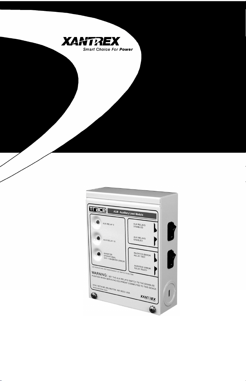
Auxiliary Load Module
Page 2

About Xantrex
Xantrex Technology Inc., is a world-leading supplier of advanced power
electronics and controls with products from 50 watt mobile units to 1 MW utilityscale systems for wind, solar, batteries, fuel cells, microturbines, and backup power
applications in both grid-connected and stand-alone systems. Xantrex products
include inverters, battery chargers, programmable power supplies, and variable
speed drives that convert, supply, control, clean, and distribute electrical power.
Trademarks
Trace and Xantrex are registered trademarks of Xantrex International.
Notice of Copyright
Auxiliary Load Module (ALM) Owner’s Manual © September 2001 Xantrex
Technology Inc. All rights reserved.
Disclaimer
While every precaution has been taken to ensure the accuracy of the contents
of this guide, Xantrex International assumes no responsibility for errors or
omissions. Note as well that specifications and product functionality may change
without notice.
Since the use of this manual and the conditions or methods of installation,
operation, use and maintenance of the unit are beyond the control of Xantrex
Technology Inc., the company does not assume responsibility and expressly
disclaims liability for loss, damage, or expense arising out of or any way connected
with such installation, operation, use, or maintenance.
Due to continual improvement through product updates, photographs and/or
illustrations used in this manual may not
Technology Inc., reserves the right to update this product without notice or releasing
an updated manual when
fit, form or function
exactly
match your unit. Xantrex
are not affected.
Date and Revision
September 2001, Revision A
Part Number
975-0027-01-01
Contact Information
Web: www.xantrex.com
Email: tracewarranty@traceengineering.com
Phone: 360/435.8826
Fax: 360/435.2229
©2001 Xantrex Technology Inc.
P/N 975-0027-01-01 Rev A 09/01
Page 3

TT
able of Cable of C
T
able of C
TT
able of Cable of C
ontentsontents
ontents
ontentsontents
1.0 INTRODUCTION1.0 INTRODUCTION
1.0 INTRODUCTION
1.0 INTRODUCTION1.0 INTRODUCTION
Unpacking and Inspection ...................................................................................1
Controls and Indicators ........................................................................................2
Indicator LEDs ..................................................................................................2
AUX RELAY 9 LED........................................................................................2
AUX RELAY 10 LED......................................................................................2
INVERTER OPERATIONAL LED..................................................................2
Switches ............................................................................................................3
AUX RELAY Switch .......................................................................................3
INVERTER ERROR Switch ........................................................................... 3
Internal Components ............................................................................................4
Relays ....................................................................................................................4
Relay Connections.................................................................................................4
Relay Terminal Block ....................................................................................4
Ground Stud.................................................................................................5
Fuses ..................................................................................................................... 5
2.0 INST2.0 INST
2.0 INST
2.0 INST2.0 INST
3.0 OPERA3.0 OPERA
3.0 OPERA
3.0 OPERA3.0 OPERA
ALLAALLA
TIONTION
ALLA
TION
ALLAALLA
TIONTION
Tools Required ......................................................................................................7
Pre-Installation ......................................................................................................7
Mounting ...............................................................................................................8
Wiring .................................................................................................................. 10
Terminal Block Wiring .................................................................................... 10
RY 11 Error Indicator Wiring .............................................................................. 11
Communication Cable ........................................................................................ 12
Internal Sticker ....................................................................................................13
TIONTION
TION
TIONTION
Test Procedures ...................................................................................................15
Operation ............................................................................................................ 16
Active-High Type Relay ................................................................................... 16
Active-Low Type Relay .................................................................................... 16
ALM Applications ...............................................................................................16
Active-High Configurations ................................................................................ 17
High-Voltage Alarm ........................................................................................17
Battery Exhaust Fan Controller ...................................................................... 17
Exhaust Fan Electrical Wiring.........................................................................18
Simple Charge Controllers .............................................................................18
Photovoltaic Charge Controller ................................................................. 18
Over-Voltage Protection Using a Grid-Tie Inverter ...................................19
Active-Low Configurations..................................................................................20
DC Load Controller .........................................................................................20
Load Diversion Controller ..............................................................................20
Low-Voltage Alarm ......................................................................................... 21
..............................................................................................................................................
.......................................................................
..............................................................................................................................................
....................................................................................................................................................
..........................................................................
....................................................................................................................................................
........................................................................................................................................................
............................................................................
........................................................................................................................................................
1515
15
1515
11
1
11
77
7
77
©2001 Xantrex Technology Inc.
P/N 975-0027-01-01 Rev A 09/01
i
Page 4

TT
able of Cable of C
T
able of C
TT
able of Cable of C
(continued)(continued)
(continued)
(continued)(continued)
ontentsontents
ontents
ontentsontents
4.0 TROUBLESHOOTING4.0 TROUBLESHOOTING
4.0 TROUBLESHOOTING
4.0 TROUBLESHOOTING4.0 TROUBLESHOOTING
5.0 SERVICE INFORMA5.0 SERVICE INFORMA
5.0 SERVICE INFORMA
5.0 SERVICE INFORMA5.0 SERVICE INFORMA
6.0 WARRANTY6.0 WARRANTY
6.0 WARRANTY
6.0 WARRANTY6.0 WARRANTY
7.0 SPECIFICA7.0 SPECIFICA
7.0 SPECIFICA
7.0 SPECIFICA7.0 SPECIFICA
Electrical .............................................................................................................. 29
Mechanical ..........................................................................................................29
............................................................................................................................................................
..............................................................................
............................................................................................................................................................
TIONSTIONS
TIONS
TIONSTIONS
........................................................................................................................
............................................................
........................................................................................................................
TIONTION
............................................................................................................
TION
......................................................
TIONTION
............................................................................................................
........................................................................................................................................
....................................................................
........................................................................................................................................
2323
23
2323
2525
25
2525
2727
27
2727
2929
29
2929
ii
©2001 Xantrex Technology Inc.
P/N 975-0027-01-01 Rev A 09/01
Page 5
1.0 INTRODUCTION
The Auxiliary Load Module (ALM) is an accessory for selected Trace™/Xantrex
inverter/charger models allowing battery voltage related tasks such as controlling
charging sources, loads, etc., and inverter error indication. The unit contains three
relays providing normally open (N.O.), normally closed (N.C.) and common (COM)
contacts. Relays RY9 and RY10 are independently adjustable DC auxiliary signal
relays. Relay RY11 is used to indicate an error condition (via an external indicator)
whenever the inverter’s output is shutdown. This could be a bell, buzzer, light, etc.
The unit interfaces with the inverter through a phone-type cable. Commands
from the inverter control the relays when defined parameters (programmed via the
inverter’s control device, e.g., display panel or remote control) are met. Refer to the
inverter operator’s manual for setting the various parameters for operation.
Front panel LEDs provide a visual display of relay activity whenever a relay
contact receives an engage command from the inverter. A highly visible blue LED
indicates the connected inverter is operational.
Unpacking and Inspection
Carefully inspect the contents of the shipping carton for damages. Report any
damages to the carrier immediately.
The following items are packed with the ALM:
• Auxiliary Load Module unit (ALM)
• 25-foot cable
• Operator’s manual
• Warranty Card
Report any missing items to your dealer immediately.
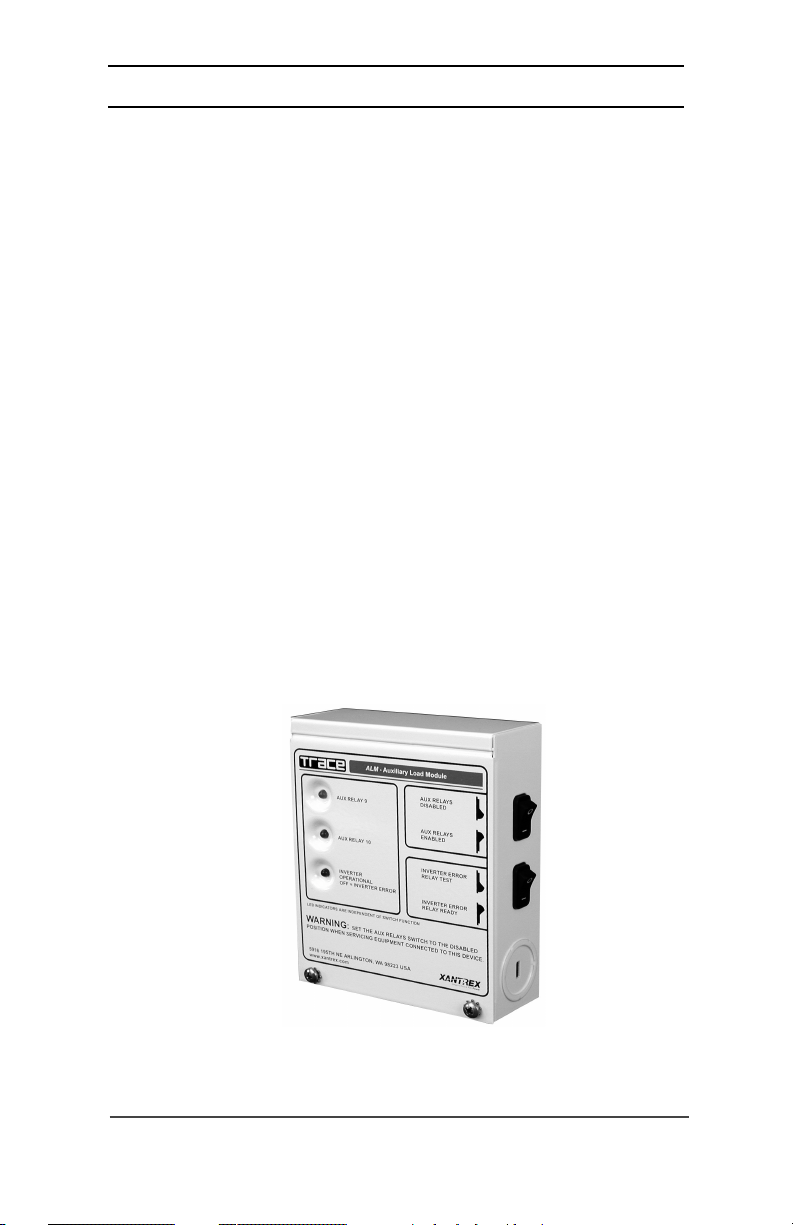
Auxiliary Load Module (ALM)
©2001 Xantrex Technology Inc.
P/N 975-0027-01-01 Rev A 09/01
Figure 1-1
1
Page 6
1.0 INTRODUCTION
Controls and Indicators
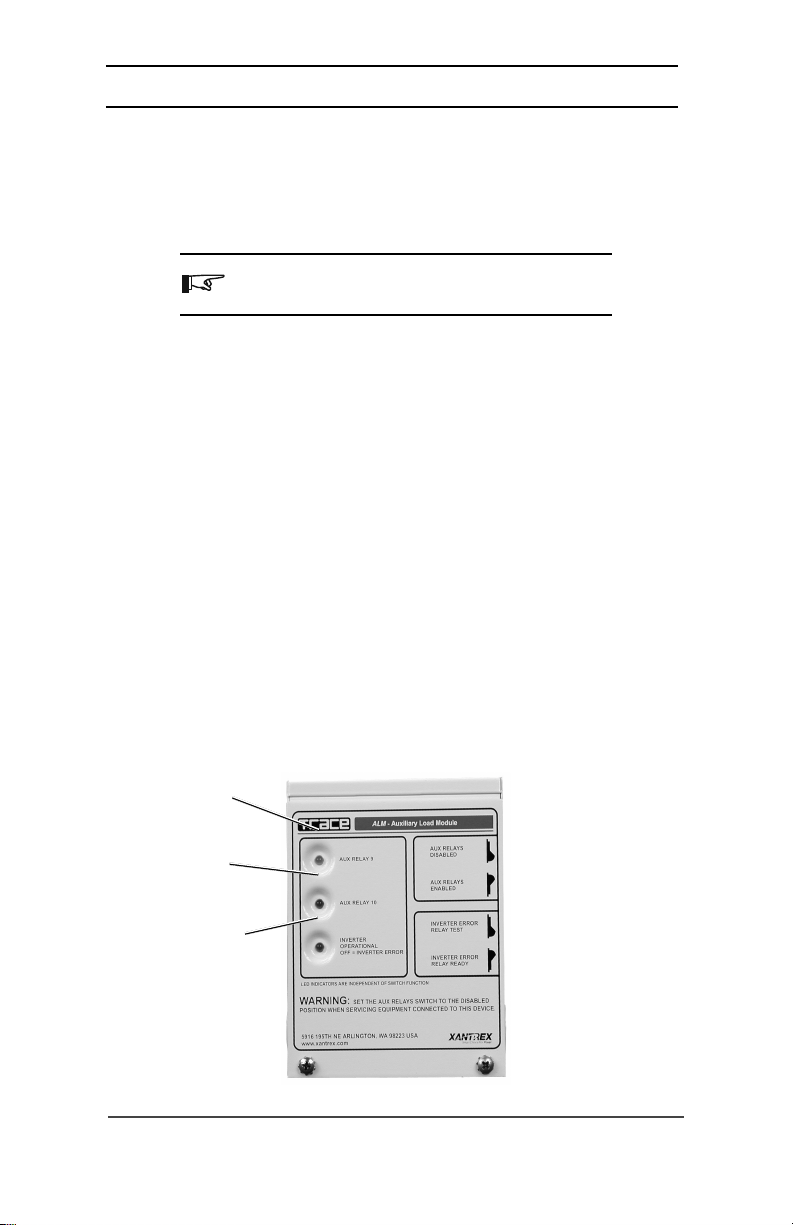
Indicator LEDs
Three LEDs located on the front panel of the ALM indicate the relay control
signal status from the inverter.
NOTE: The LEDs are unaffected by the ALM’s switch
positions or fuse condition.
AUX RELAY 9 LED
The yellow LED indicates whether relay RY9 has engaged or not. If this LED is
illuminated, the N.O. to COM contacts are connected. If this LED is not illuminated,
the N.C. to COM contacts are connected.
AUX RELAY 10 LED
The green LED indicates whether relay RY10 has engaged or not. If this LED is
illuminated, the N.O. to COM contacts are connected. If this LED is not illuminated,
the N.C. to COM contacts are connected.
INVERTER OPERATIONAL LED
The blue LED indicates the inverter’s operational status. If the inverter is
powered and ready for operation, the blue SYSTEM OPERATIONAL LED turns ON as
soon as the phone-type cable is plugged into the inverter. If the blue LED does not
turn ON, the inverter is either not powered, is set to the CHG-only mode without any
utility pass-through, or has no AC output which may be caused by an error
condition.
Yellow LED
AUX RELAY 9
Green LED
AUX RELAY 10
Blue LED
INVERTER OPERATIONAL
OFF = INVERTER ERROR
2
Figure 1-2
Indicator LEDs
©2001 Xantrex Technology Inc.
P/N 975-0027-01-01 Rev A 09/01
Page 7
1.0 INTRODUCTION
Controls and Indicators (continued)
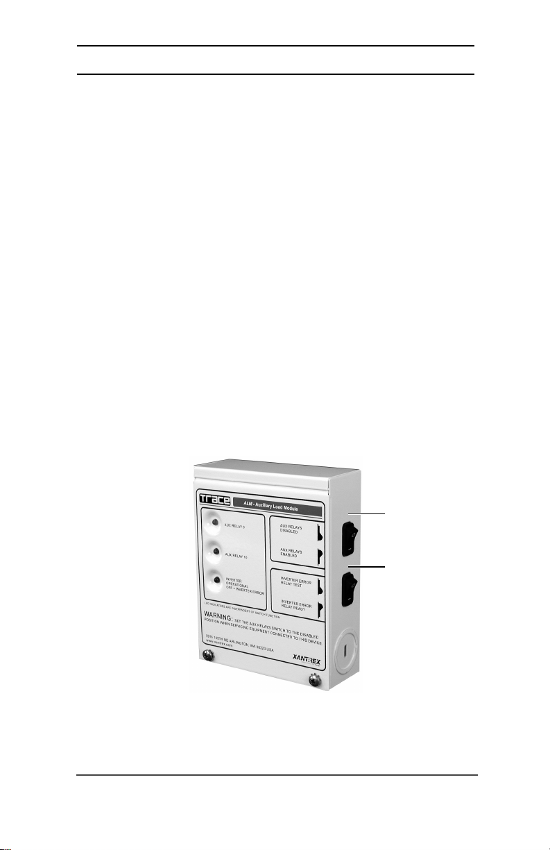
Switches
Two switches are provided on the right side of the ALM to effectively
disconnect the relay coils from the inverter’s supply voltage (11 VDC), thus
preventing the relays from engaging if a control signal is sent out from the inverter.
This safety feature allows you to work with the auxiliary relays without having to
power-down the connected inverter.
AUX RELAY Switch
The AUX RELAY switch enables the relays by providing the operating voltage to
the relay coils RY9 and RY10. When the relays are enabled, they will respond to the
control signals provided by the inverter. When the switch is in the RELAYS
DISABLED position, the inverter control signals have no effect on relay operation
(i.e., the COM and N.C. contacts engage). This switch does not affect the operation
of the LEDs which continue to light whenever the inverter sends a CLOSE CONTACT
command to the relays.
INVERTER ERROR Switch
The INVERTER ERROR switch provides a simple way to test an externally
connected alarm. Once the alarm is tested, this switch should be set to the RELAY
READY position.
©2001 Xantrex Technology Inc.
P/N 975-0027-01-01 Rev A 09/01
Figure 1-3
Switches
AUX RELAY Switch
(RY9 and RY10)
INVERTER ERROR
Switch (RY 11)
3
Page 8
1.0 INTRODUCTION
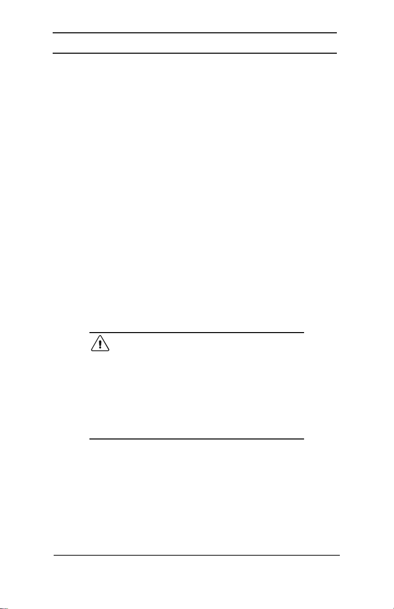
Internal Components
The Auxiliary Load Module (ALM) is designed for multiple applications and
allows for simple installation. Components provided are listed below.
Relays
There are three single-pole, double-throw relays, rated at 10 amps/250 VAC
(8 amps/30 VDC–for resistive loads), with gold contacts providing “dry contact”
closures to increase the low-end signal range.
• Relay RY9 and RY10 are used for battery voltage related functions.
• Relay RY11 can be connected to an external indicator device to display or
sound an alarm whenever the inverter AC output is lost.
• The common, normally open , and normally closed contacts are available on
each relay.
Relay Connections
• Common (COM) - The COM contact switches between the N.C. and N.O.
terminals depending on whether the relay is energized or not (de-energized).
• Normally Closed (N.C.) - The N.C. contact is connected to the COM terminal
of the relay when the relay is de-energized.
• Normally Open (N.O.) - The N.O. contact is connected to the COM terminal
of the relay when the relay is energized.
CAUTION: These relays are not intended to directly
control a load or charging source. Rather they are used
to send a signal or operate the coil of another, higher
amperage device which does the actual switching of
power. A 6.3-amp fuse is included to help protect each
of the relays. Connection to a high amperage device
will open the fuse in the common line and possibly
damage the relay. Damage to these relays from
overloading is not covered by warranty and requires the
ALM to be returned to a repair center.
Relay Terminal Block
Connections to the ALM are accomplished by the nine position, spring-clamp,
terminal block with quick connect levers. All relay contacts (N.O., COM, and N.C.)
are available at this connector, which accepts wire sizes from #28 AWG to #14 AWG.
No tools are required to secure the wires as the spring clamp holds the wires
securely in place.
4
©2001 Xantrex Technology Inc.
P/N 975-0027-01-01 Rev A 09/01
Page 9
1.0 INTRODUCTION
Internal Components (continued)
Ground Stud
A ground screw is provided in the ALM to provide a safety ground path when
hazardous voltages are connected to the relays. Connect this screw to a grounded
conductor whenever high voltages (i.e., above 60 volts) are connected to the relays.
NOTE: No hazardous voltages are supplied from the
inverter to power or control the relays; however, 120 VAC
could be used to power an external error indicator.
Fuses
Each relay’s common (COM) contact is protected with a 6.3 amp
(5 mm x 20 mm) 250 VAC fuse which will open if excess current is drawn
through the relay contacts. Always replace this fuse with the same type and
rating. Type GDC (Bussman) or 218 (Littlefuse) is recommended.
NOTE: These fuses can be replaced with
fuses to also protect the connected circuitry, if desired. In
no no
no case, should this fuse be replaced with one of a
no no
amperage.
F1 protects
RY 9
Communication jack
J1
GROUNDING screw
F2 protects
RY 10
Figure 1-4
Internal Components
lower lower
lower amperage
lower lower
higherhigher
higher
higherhigher
F3 protects
Terminal Block
RY 11
©2001 Xantrex Technology Inc.
P/N 975-0027-01-01 Rev A 09/01
5
Page 10

1.0 INTRODUCTION
Notes:
6
©2001 Xantrex Technology Inc.
P/N 975-0027-01-01 Rev A 09/01
Page 11
2.0 INSTALLATION
The ALM is required to be installed in a clean, dry, protected environment and
should be mounted close to the load in a location where it is easily accessible. Dual
knockouts, in the sizes of ½, ¾ and 1 inch, are provided for cable routing and
conduit connections. Mount the ALM to a flat, vertical surface, such as a wall.
Tools Required
screwdrivers (Phillips and flat blade) wood screws (#10)
drill and assorted bits anchors (if required)
wire strippers
WARNING: BEFORE MAKING ANY CONNECTIONS
TO THE LOAD OR INVERTER, ENSURE THAT ALL AC
AND DC POWER IS DISCONNECTED FROM THE
INVERTER AND THE ALM.
Pre-Installation
Before installing the ALM, read all instructions and cautionary markings
located in this manual.
Determine the wire route (or conduit runs) to the ALM and loads.
NOTE: Check for existing electrical, plumbing, or other
potential areas of accidental damage prior to making cuts
in structural surfaces.
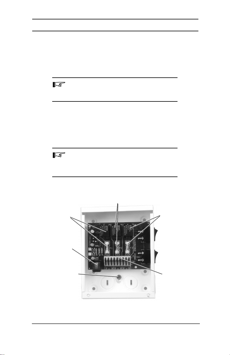
6-9/64
4-27/32
1-13/64
19/32
Dimensional Drawing (Not to Scale)
©2001 Xantrex Technology Inc.
P/N 975-0027-01-01 Rev A 09/01
19/32
SW1
SW2
J1
3-11/16
4-7/8
Figure 2-1
7
Page 12

2.0 INSTALLATION
Mounting
• Remove the two Phillips screws from the unit’s front panel and remove the
cover. Figure 2-2.
• Open the inverter’s access panel and locate the AUX connector if necessary.
Refer to the inverter operator’s manual for the location of the connector.
• Hold the ALM against the surface to be mounted and use the unit as a
template to mark the four hole locations. See Figure 2-3.
NOTE: Six holes are provided in the back panel of the
ALM. Use the two top and two bottom screw holes. Do
not use the middle two holes.
• Drill holes for mounting and insert appropriate anchors if necessary.
• Use four #10 wood screws to mount the unit to the wall or other vertical
surface.
• Install conduit runs or strain reliefs for the RY9 and RY10 control wires, error
indicator (if used), and communication cable (between the inverter and ALM).
Remove the 2
Phillips screws
Figure 2-2
Removing the Front Cover
8
©2001 Xantrex Technology Inc.
P/N 975-0027-01-01 Rev A 09/01
Page 13

Mounting (continued)
2.0 INSTALLATION
Mounting
Hole
Do NOT use
this hole
for mounting.
Mounting
Hole
1/2" - 3/4"
Dual
Knockouts
Figure 2-3
Mounting Holes
Mounting
Hole
Do NOT use
this hole
for mounting.
3/4" - 1"
Dual
Knockouts
3/4" - 1"
Dual
Knockouts
©2001 Xantrex Technology Inc.
P/N 975-0027-01-01 Rev A 09/01
Figure 2-3a
Dual Knockout Locations
1/2" - 3/4"
Dual
Knockouts
3/4" - 1" Dual
Knockouts
9
Page 14
2.0 INSTALLATION
Wiring
NOTE: All wiring described in this manual must be
performed by a qualified, licensed electrician and meet
local and national codes, such as NEC.
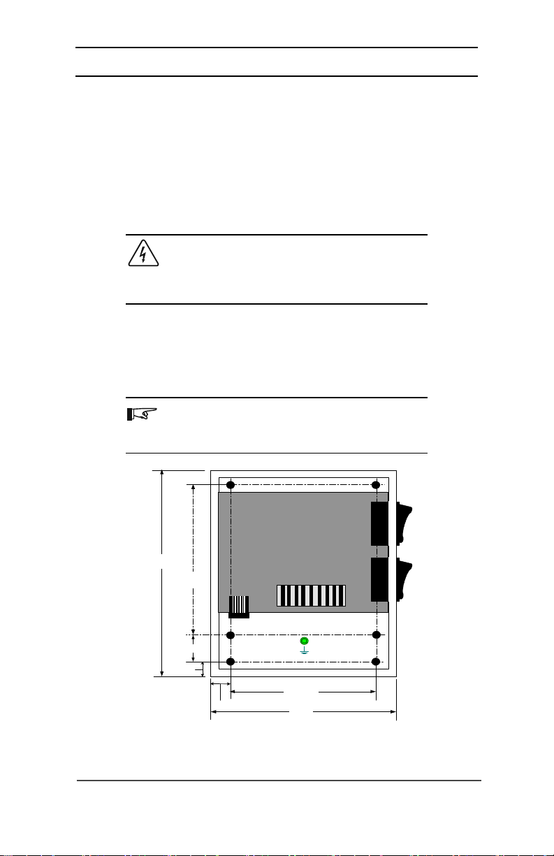
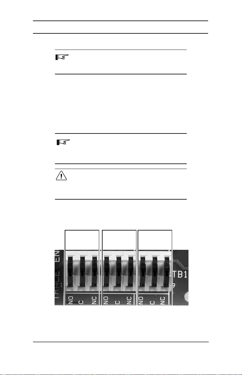
Terminal Block Wiring
• Lift the appropriate lever for the relay contact.
• Insert the wire (stripped back 1/4 inch) into the terminal block.
• Snap the lever down to secure the wire.
Please refer to the auxiliary relay section of the inverter’s operation manual for
additional information.
NOTE: Due to the various ways the ALM can be wired,
detailed wiring instructions can not be given in this
manual. Please refer to the operation section of this
manual for wiring suggestions.
CAUTION: Do not wire the relays directly to a highamperage device. Connection to a high-current device
will open the fuse in the common line and possibly
damage the relay.
10
RELAY 9
Connections
RELAY 10
Connections
Connections
Figure 2-4
Terminal Block Connections
RELAY 11
©2001 Xantrex Technology Inc.
P/N 975-0027-01-01 Rev A 09/01
Page 15

2.0 INSTALLATION
RY 11 Error Indicator Wiring
If an error indicator is used (light, buzzer, bell, etc.), connect the wires to the
RY11 relay contacts. Depending on the error indicator used, either the N.O. or N.C.
contacts can be used. Typically, the N.C. and COM contacts are used to complete a
circuit, turning on a light, buzzer, etc. The N.C. contacts are held “open” until an
error condition is detected (or the AC output is OFF); at which time the N.C. contact
will “close” completing the circuit and activating the external device.
CONTROL SIGNAL
FROM INVERTER
(relay engaged)
ALM
COM
N.C.
N.O.
EXTERNAL
INDICATOR
POWER SOURCE
External Error
Indicator
External Alarm
OFF Switch
NO SIGNAL FROM
INVERTER
(relay disengaged)
ALM
COM
N.O.
EXTERNAL
INDICATOR
POWER SOURCE
External Error
N.C.
Figure 2-5
External Error Indicator Connections
For convenience, add an external OFF switch in line with the alarm device. This
allows turning off the alarm until the inverter’s output is restored.
NOTE: The diagrams shown here are intended as an
example of how the relays operate an external alarm
device. Actual alarm types may operate differently from
these diagrams. Refer to the external indicator’s owner’s
manual for specific alarm wiring. Do not exceed the
voltage or amperage ratings of the relay and fuse.
NO SIGNAL FROM
INVERTER
(relay disengaged)
External Error
Indicator
Indicator
External Alar m
OFF Switch
ALM
COM
©2001 Xantrex Technology Inc.
P/N 975-0027-01-01 Rev A 09/01
N.C.
N.O.
EXTERNAL
INDICATOR
POWER SOURCE
External Alarm
OFF Switch
Figure 2-6
External Alarm OFF Switch
11
Page 16
2.0 INSTALLATION
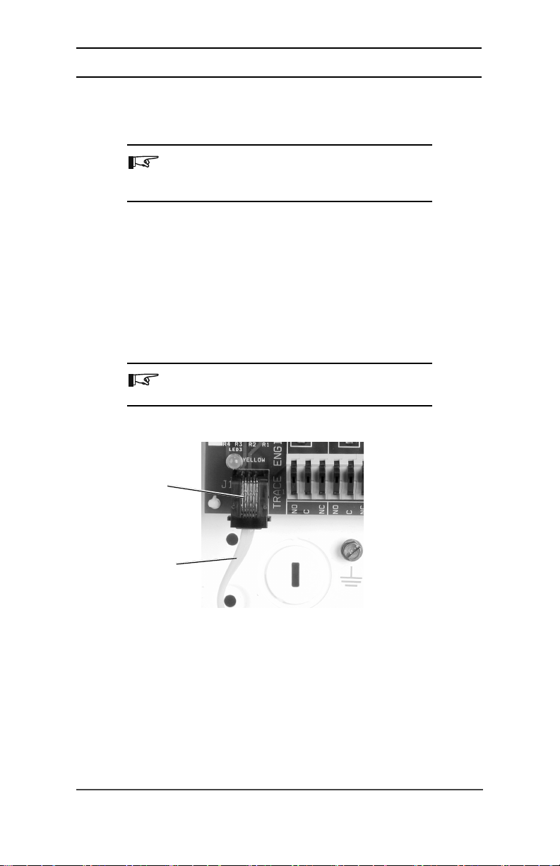
Communication Cable
The ALM is supplied with a 25-foot, telephone-type, cable with RJ11 connectors
on each end.
NOTE: Longer cable lengths are available for purchase
from your Xantrex Dealer: part numbers TC/50 for 50 feet
(15.24 m) and TC/100 for 100 feet (30.48 m).
• Route the telephone-type cable through one of the knockouts fitted with a
strain relief (or conduit).
• Connect one end of the cable to the jack labeled J1 on the ALM circuit board.
• Connect the other end of the cable to the jack labeled AUX inside the inverter
(refer to the inverter’s operator’s manual for location).
• Reinstall the cover on the ALM using the two Phillips screws.
• Reinstall the inverter’s cover.
NOTE: Recheck all wiring before proceeding to the
Operation section of this manual.
12
J1 Connector
Communication
cable to inverter
J1 Control Signal Connection
Figure 2-7
©2001 Xantrex Technology Inc.
P/N 975-0027-01-01 Rev A 09/01
Page 17

2.0 INSTALLATION
Internal Sticker
Please refer to the component layout sticker located inside the front cover.
This label can be used as a quick reference for component location and fuse sizing
information.
™
ALM - AUXILI ARY LOAD MODUL E
SUPPLIED FUSE RATING: 6.3 AMP 250VAC
FUSE TYPE: 5mm X 20mm
MAXIMUM RELAY CONTACT RATINGS: (RESISTIVE LOAD)
10 AMPS @ 250VAC
8 AMPS @ 30VDC
FUSE SHOULD BE SELECTED FOR PROPER
PROTECTION OF CONNECTED DEVICES.
(DO NOT EXCEED RELAY CONTACT RATING)
PN 110-0035 - -
R4
RELAY
LED1
RY9
SW1
LED2
D1
LED3
F1
R1R2R3
J1
NOCNC
Interconnect cable (J1):
WARNING:
Internal Component Identification Sticker
©2001 Xantrex Technology Inc.
P/N 975-0027-01-01 Rev A 09/01
RELAY
RY10
SW1
RELAY
RY11
SW2
SW1
F3F2
SW2
TB1
91
NCCCNONO
NC
Terminal Bl ock wire size: 14-28 AWG
Wire strip length: .25" (6mm)
Connect to Gen Port of
Trace Inve rter
DO NOT O PERATE WITH CO VER REMOVED.
HAZARDOUS VOLTAGES MAY BE PRESENT.
Figure 2-8
13
Page 18

2.0 INSTALLATION
Notes:
14
©2001 Xantrex Technology Inc.
P/N 975-0027-01-01 Rev A 09/01
Page 19

3.0 OPERATION
Test Procedures
NOTE: Refer to the inverter’s operator’s manual for
setting the RY11 relay for testing.
Immediately after installation, the ALM should be tested for proper operation.
• Ensure the AUX RELAY switch on the ALM is in the ON (ENABLED) position
and the INVERTER ERROR relay is in the RELAY READY position.
• Reconnect all power to the inverter.
• Using the inverter’s control device (i.e., display, SWRC remote), press the
INV MENU button to access the inverter menu. Select ON from the display.
The blue INVERTER OPERATIONAL LED should immediately turn ON.
NOTE: The LEDs will turn ON differently, depending
upon the function selected from your inverter.
• If an external alarm is connected to the ALM, turn the INVERTER ERROR
switch to the RELAY TEST position. The external device should activate.
• Place the INVERTER ERROR switch in the RELAY READY position.
NOTE: If the tests did not pass, recheck the wiring and
the ALM for proper relay contact selection (N.O. or N.C.).
©2001 Xantrex Technology Inc.
P/N 975-0027-01-01 Rev A 09/01
15
Page 20

3.0 OPERATION
Operation
The inverter that is connected to the ALM monitors its battery voltage to
determine when to signal relays RY9 and RY10. These relays are individually
controlled and each responds to user-programmable, voltage setpoints via the
inverter’s control panel. These two auxiliary relays operate independently of the
inverter’s status - whether the inverter is ON or OFF.
The software revision of your inverter determines whether RY9 and RY10
operate as active-high or active-low type relays. This depends on whether the
inverter has:
1) the programming to allow for a “user-defined delay” when the relay energizes
or de-energizes,
2) a hysteresis voltage setting (the difference between the relay activation and
deactivation), or
3) a temperature compensation setting.
For specifics on the operation, programming, and adjustment values for the
ALM, refer to your inverter’s manual (Auxiliary Relay section).
Active-High Type Relay
This relay type energizes when the voltage is above the high-voltage setpoint
and de-energizes when the voltage goes below the low-voltage setpoint.
Active-Low Type Relay
This relay type energizes when the voltage is below the low-voltage setpoint
and de-energizes when the voltage goes above the high-voltage setpoint.
ALM Applications
There are a number of applications for the ALM. These applications are based
on the configuration of the relays – whether configured active-high or active-low.
16
©2001 Xantrex Technology Inc.
P/N 975-0027-01-01 Rev A 09/01
Page 21

3.0 OPERATION
Active-High Configurations
High-Voltage Alarm
The ALM can be configured to monitor the inverter’s battery voltage and to
engage an external alarm when the battery voltage increases above a safe level.
BATTERY VOLTAGE IS WITHIN ACCEPTABLE LIMITS
External
Inverter
AUX
ALM
Communications
J1
COM
INDICATOR POWER
Cable
N.C.
N.O.
EXTERNAL
SOURCE
Error
Indicator
External
Alarm OFF
Switch
BATTERY VOLTAGE EXCEEDS ACCEPTABLE LIMITS
External
Indicator
External
Alarm OFF
Switch
Inverter
AUX
ALM
COM
Communications
Cable
J1
N.C.
N.O.
EXTERNAL
INDICATOR POWER
SOURCE
Error
Figure 3-1
High-Voltage Alarm Configuration
Battery Exhaust Fan Controller
Use the ALM to ventilate enclosed battery compartments to remove explosive
gasses, acid fumes, excess heat, and humidity. The ALM can be connected to
automatically turn on exhaust fans when the battery reaches its gassing voltage and
turn off the fan once the battery voltage returns to a lower level.
Exhaust
Fan
Outdoors
Screened
facing down
Outlet
Indoors
• Use PVC DWV pipe and fittings.
• Use curved elbows as opposed to sharp 90° turns.
• Limit elbow turns to a maximum of four.
• Install exhaust fan vertically with la bel right side up.
Do NOT glue these joints.
Exhaust
Fan
Screened Intake Vent
• Must have a 2-inch diameter (minimum).
• Locate near b ottom of battery box, opposit e from outlet.
Exhaust Fan Installation Diagram
©2001 Xantrex Technology Inc.
P/N 975-0027-01-01 Rev A 09/01
Battery Box
Figure 3-2
Outlet to Exhaust Fan
• Locate near top of battery box, opposit e from intake vent.
• Must have a 2- inch diameter (minimum).
17
Page 22

3.0 OPERATION
Exhaust Fan Electrical Wiring
Outdoors
+
Exhaust
Fan
-
Exhaust Fan OFF
AUX
Inverter
ALM
COM
Indoors
Communications
Cable
J1
N.C.
N.O.
+
BATTERY BANK
Outdoors
Indoors
Exhaust Fan ON
Communications
AUX
COM
Cable
J1
N.C.
N.O.
+
BATTERY B ANK
-
Inverter
+
Exhaust
Fan
-
ALM
-
Figure 3-3
Exhaust Fan Electrical Wiring
Simple Charge Controllers
These configurations for the ALM provide over-voltage protection for your
batteries.
Photovoltaic Charge Controller
The ALM can be used to control the charging of batteries from a solar array.
The relays can be adjusted to open if the PV array’s output increases above the
maximum charge voltage and to automatically reconnect when the voltage falls to a
“resume” recharge voltage level.
18
PV ARRAY IS CHARGING THE
BATTERIES
External Power Relay
N.C.
120 VAC
Coil
Communic ations
Inverter
ALM
Cable
AUX
J1
N.C.
COM
N.O.
N.O.
COM
+
PV Array
-
+
BATTERY BANK
Using the ALM as a Photovoltaic Charge Controller
-
Figure 3-4
PV ARRAY IS NOT CHARGING THE
BATTERIES
External Power Relay
N.C.
120 VAC
Coil
Communic ations
Inverter
ALM
Cable
AUX
J1
N.C.
COM
N.O.
COM
N.O.
+
PV Array
-
+
BATTERY BANK
©2001 Xantrex Technology Inc.
P/N 975-0027-01-01 Rev A 09/01
-
Page 23

3.0 OPERATION
Over-Voltage Protection Using a Grid-Tie Inverter
Normally, the grid-tie inverter will regulate the charging process of the battery
by selling excess power into the utility grid. If the utility grid is not available (due to
an outage or tripped AC input circuit breaker, etc.) or if the inverter shuts off, the
inverter is not able to sell the excess power and the battery voltage will not be
regulated, resulting in possible overcharging of the battery.
Therefore, the ALM can be configured to provide over-voltage protection for the
battery when a utility outage has occurred. These relays can be configured to control
an externally connected, power relay that disconnects the solar array and stops the
charging process. The external relay can be either a standard mechanical type or a
mercury displacement type, depending on the voltage and current required. The
mercury displacement type relay is usually required when the system voltage is
48 VDC or if the current of the solar array exceeds about 20 amps. Multiple relays
can be used if the solar array is divided into several source circuits (do not parallel
relays for higher current).
A typical wiring configuration for this over-voltage protection is shown in
Figure 3-5.
This circuit does draw a small amount of power all of the time to power the coil
of the relay. This circuit provides protection against overcharging the batteries.
Photovoltaic
Array
AC Output - Neutral
AC Output - Hot
Inverter
AUX
Communications Cab le
J1
ALM
COM
©2001 Xantrex Technology Inc.
P/N 975-0027-01-01 Rev A 09/01
N.C.
N.O.
Over-Voltage Protection using a Grid-Tie Inverter
-
+
Figure 3-5
External Power Relay
120 VAC
Coil
N.O.
+
N.C.
COM
+
BATTERY BANK
-
-
19
Page 24

3.0 OPERATION
Active-Low Configurations
DC Load Controller
The ALM can also be configured to operate as a load controller to manage the
discharging of the inverter’s battery. (See Figure 3-6.) A load controller prevents
damage to the battery from over-discharge during periods of poor charging or
excessive loads. The ALM also can provide automatic reconnection of the loads at
the reconnect setting. Reconnection of the load is allowed once the battery voltage
has exceeded your reconnect setting. When used as a DC load controller, the user
adjustments, enabled by your inverter’s control device, control the reconnect and
disconnect settings.
BATTERY VOLTAGE IS WITHIN
ACCE PTABLE LIMI TS
External Power Relay
N.C.
120 VAC
COM
Coil
Communications
Inverter
ALM
Cable
AUX
J1
N.C.
COM
N.O.
N.O.
+
DC Load
-
+
BATTERY BANK
-
BATTERY VOLTAGE IS BELOW
ACCEPTABLE LIMITS
External Power Relay
N.C.
120 VAC
Coil
COM
Communications
Inverter
Cable
AUX
J1
N.C.
ALM
COM
N.O.
N.O.
+
-
+
BATTERY BANK
DC Load
-
Figure 3-6
Using the ALM as a DC Load Controller
Diversion Load Controller
Diversion load controllers (also known as wind or Hydro-Dump controllers)
operate by diverting excess charge current from the battery that is being charged to
another load, for example, power resistors, water heater, etc. (See Figure 3-7.) This
prevents damage to the charging source from an over-speed condition that could
occur if the charging source is suddenly disconnected from all loads. Even with a
solar-based system, it may be desirable to use this configuration to divert excess PV
power to operate DC loads.
When the ALM is configured this way, its setpoint would energize the relay to
energize a contactor (one that could handle the excess current). This would allow
the excess charge current to divert to the “dump load” thereby preventing
overcharged batteries.
20
CAUTION: If you are using AC loads as your diversion
load through the inverter, be aware that you may
overcharge your battery if the inverter fails or is
turned OFF.
©2001 Xantrex Technology Inc.
P/N 975-0027-01-01 Rev A 09/01
Page 25

3.0 OPERATION
When using this type of configuration, the separate diversion or “dump” load
must be able to absorb more power than the charging source is able to produce at
its peak output; otherwise, the DC voltage becomes unregulated. The current draw
of the diversion load is very important. Problems can arise from operating with a
load that is too small or too large. A diversion load that is too small will not be able
to absorb all the excess power from the current source once the batteries are full; a
load that is too big may cause a large in-rush of current above the design rating of
the relay, causing premature failure. A good design practice is to use a diversion
load that draws about 25% more current than the charging source’s maximum
output capability. The diversion load must be available for the diversion of power at
all times. Resistive-type heating elements are the best diversion loads. Special
direct current water heating elements are available. Light bulbs and motors are not
recommended.
BATTERY VOLTAGE IS WITHIN
ACCEPTABLE LIMITS
BATTERY VOLTAGE EXCEEDS
ACCEPTABLE LIMITS
External Power Relay
N.C.
120 VAC
Coil
Communications
Inverter
ALM
COM
Cable
AUX
J1
N.C.
N.O.
COM
N.O.
DIVERSION
LOAD
+
BATTERY BANK
-
External Power Relay
N.C.
120 VAC
Coil
Communications
Inverter
ALM
Cable
AUX
J1
N.C.
COM
N.O.
N.O.
COM
+
BATTERY BANK
Figure 3-7
Using the ALM as a Diversion Load Controller
Low-Voltage Alarm
The ALM can be configured to monitor the inverter’s battery voltage and to
engage an external alarm when the battery voltage decreases to a low level.
INVERTER'S BATTERY VOLTAGE IS WITHIN
ACCEPTABLE LIMITS
External
Error
Indicator
External
Alarm OFF
Inverter
AUX
ALM
COM
Communications
Cable
J1
N.C.
N.O.
EXTERNAL
INDICATOR POWER
SOURCE
Switch
INVERTER'S BATTERY VOLTAGE IS BELO W
ACCEPTABLE LIMITS
Communications
Inverter
AUX
ALM
COM
Cable
J1
N.C.
N.O.
EXTERNAL
INDICATOR POWER
SOURCE
DIVERSION
LOAD
External Error
Indicator
External
Alarm OFF
Switch
-
Low-Voltage Alarm Configuration
©2001 Xantrex Technology Inc.
P/N 975-0027-01-01 Rev A 09/01
Figure 3-8
21
Page 26

3.0 OPERATION
Notes:
22
©2001 Xantrex Technology Inc.
P/N 975-0027-01-01 Rev A 09/01
Page 27

4.0 TROUBLESHOOTING
The ALM contains no serviceable parts other than the three fuses in the
common contact circuit of the relays. If the module requires servicing, return it to
an authorized Xantrex Technology Inc., service center or contact a Xantrex
representative for assistance.
motpmyS esuaCelbissoP ydemeR
.thgiltonseodDELeulB.NOdenruttonretrevnI
tonelbacnoitacinummoC
.kcajgnorweht
.edom)ylno
neerg,sthgilDELeulB
.thgil
.krowton
.etanimulliton
tonodsDELwolleydna
sDELwolleydnaneerG
seodtiucricehttubthgil
ehttubetautcasyaleR
seodDELgnidnopserroc
.launams'rotarepos'retrevni
.noitisopFFO
.nepo)s(esuF
.DELdaB.decivrestinuehtevaH
nisiroretrevniotdetcennoc
.detcetedrorreretrevnI
.ediug
egrahc(RHCnisiretrevnI
.yltcerrocputestonsiretrevnIehtfoputesehtkcehC
ehtnisihctiwSyaleRxuA
.yltcerrocnideriwtiucriC
.retrevniNOnruT
reporpehtotdetcennocsi
.retrevniehtnikcaj
ehttoohselbuorT.noitarepo
lortnoc,.e.i(ecivedlortnoc
asa)lortnocetomer,lenap
ylpparoedomehtegnahC
)rotarenegro(ytilituCA
lortnocruoygnisuretrevni
,lenaplortnoc,.e.i(ecived
otrefeR.)lortnocetomer
.launams'rotareporetrevni
.noitisopNOeht
toohselbuort,esufecalpeR
.tnerrucrevofoesuac
ehtninoitcesgnitoohselbuortehtehtotrefer,noitamrofnilanoitiddaroF:ETON
tierusnE.noitcennockcehC
reporprofretrevniehtkcehC
ruoygnisurorreehtfoesuac
.tupnis'retrevniehtotrewop
nisihctiwsreppuehterusnE
.tcerrocdnagniriwkcehceR
Troubleshooting Guide for the Auxiliary Relay Module
©2001 Xantrex Technology Inc.
P/N 975-0027-01-01 Rev A 09/01
Table 4-1
23
Page 28

4.0 TROUBLESHOOTING
Notes:
24
©2001 Xantrex Technology Inc.
P/N 975-0027-01-01 Rev A 09/01
Page 29

5.0 SERVICE INFORMATION
Xantrex Technology Inc., takes great pride in its products and makes every
effort to ensure your unit fully meets your independent powering needs.
If your product needs repair, contact our Customer Service department at:
(360) 435-8826 to obtain an RMA# and shipping information; or, fax this page with
the following information to: (360) 474-0616. You can also contact us by email at
tracewarranty@traceengineering.com.
Please provide:
Model Number: _____________________________________
Serial Number: _____________________________________
Purchase Date: _____________________________________
Problem:___________________________________________
Include a telephone number where you can be reached during business hours
and a complete return shipping address (P.O. Box numbers are not acceptable).
Name: _______________________________________________
Address: _____________________________________________
City: ________________________________________________
State / Province: _______________________________________
Zip / Postal Code: _____________________________________
Country: _____________________________________________
Phone: (__________)___________________________________
FAX: (__________)_____________________________________
E-mail Address: _______________________________________
©2001 Xantrex Technology Inc.
P/N 975-0027-01-01 Rev A 09/01
25
Page 30

5.0 SERVICE INFORMATION
Notes:
26
©2001 Xantrex Technology Inc.
P/N 975-0027-01-01 Rev A 09/01
Page 31

6.0 WARRANTY
Limited Warranty
Xantrex Technology Inc., warrants its power products against defects in
materials and workmanship for a period of two (2) years from the date of purchase,
established by proof of purchase or formal warranty registration, and extends this
warranty to all purchasers or owners of the product during the warranty period.
Xantrex Technology Inc., does not warrant its products from any and all defects:
• arising out of material or workmanship not provided by Xantrex or its
Authorized Service Centers;
• when the product is installed or exposed to an unsuitable environment as
evidenced by generalized corrosion or biological infestation;
• resulting from abnormal use of the product, alteration, or use in violation of
the instructions;
• in components, parts, or products expressly warranted by another
manufacturer.
Xantrex Technology Inc., agrees to supply all parts and labor to repair or
replace defective products covered by this warranty with parts or products of original
or improved design, at the company's option. Xantrex Technology Inc., also reserves
the right to improve the design of its products without obligation to modify or
upgrade those previously manufactured. Defective products must be returned to
Xantrex Technology Inc., or its Authorized Service Center in the original packaging or
equivalent. The cost of transportation and insurance on items returned for service is
the responsibility of the customer. Return transportation (UPS Ground or
equivalent) as well as insurance on all repaired items is paid by Xantrex Technology
Inc.
All remedies and the measure of damages are limited to the above. Xantrex
Technology Inc., shall in no event be liable for consequential, incidental, contingent,
or special damages, even if Xantrex Technology Inc., has been advised of the
possibility of such damages. Any and all other warranties, expressed or implied,
arising by law, course of dealing, course of performance, usage of trade or otherwise,
including, but not limited to, implied warranties of merchantability and fitness for a
particular purpose, are limited in duration for a period of two (2) years from the
original date of purchase.
Some states or counties do not allow limitations on the term of an implied
warranty, or the exclusion or limitation of incidental or consequential damage, which
means the limitations and exclusions of this warranty may not apply to you. Even
though this warranty gives you specific legal rights, you may also have other rights
which vary from state to state.
©2001 Xantrex Technology Inc.
P/N 975-0027-01-01 Rev A 09/01
27
Page 32

6.0 WARRANTY
Notes:
28
©2001 Xantrex Technology Inc.
P/N 975-0027-01-01 Rev A 09/01
Page 33

Specifications
Electrical
7.0 SPECIFICATIONS
Operating VOperating V
Operating V
Operating VOperating V
Operating CurrentOperating Current
Operating Current < 10 mA
Operating CurrentOperating Current
Relay CRelay C
Relay C
Relay CRelay C
Wire Size AcceptedWire Size Accepted
Wire Size Accepted 28 AWG to 14 AWG
Wire Size AcceptedWire Size Accepted
SwitchesSwitches
Switches 2 DPDT switches
SwitchesSwitches
ProtectionProtection
Protection 3–Fuses, 6.3 amps max. (5 mm x 20 mm),
ProtectionProtection
Indicator LEDsIndicator LEDs
Indicator LEDs 3–LEDs, green, yellow, and blue
Indicator LEDsIndicator LEDs
Interface CInterface C
Interface C
Interface CInterface C
Interface CInterface C
Interface C
Interface CInterface C
TT
erminal Blockerminal Block
T
erminal Block Snap-lock type connection
TT
erminal Blockerminal Block
oltageoltage
oltage 11 VDC (provided by inverter)
oltageoltage
ontact Ratingontact Rating
ontact Rating 250 VAC, 10 amps max. (resistive load only)
ontact Ratingontact Rating
able 25 ft.able 25 ft.
able 25 ft. Telephone-type cable with RJ11 plugs
able 25 ft.able 25 ft.
onnectiononnection
onnection Telephone-type RJ11 jack
onnectiononnection
30 VDC, 8 amps max. (resistive load only)
time delay
Bussman–GDC, Littlefuse–218 series
Mechanical
MaterialMaterial
Material Indoor-type, powder coated, steel enclosure for wall
MaterialMaterial
mounting
DimensionsDimensions
Dimensions 6.8" H x 4.8" W x 2.0" D
DimensionsDimensions
©2001 Xantrex Technology Inc.
P/N 975-0027-01-01 Rev A 09/01
(15.6 cm H x 12.4 cm W x 5.0 cm D)
29
Page 34

7.0 SPECIFICATIONS
Notes:
30
©2001 Xantrex Technology Inc.
P/N 975-0027-01-01 Rev A 09/01
Page 35

Page 36

t 1 360 435 8826
f 1 360 435 2229
drc@xantrex.com
www.xantrex.com
© 2001 Xantrex Technology Inc.
P/N 975-0027-01-01 Rev. A 09/01
 Loading...