

Page 1
Automatic
Generator Start
Owner’s Guide
Page 2

Page 3

Automatic Generator Start
Owner’s Guide
Page 4

About Xantrex
Xantrex Technology Inc. is a world-leading supplier of advanced power electronics and controls with
products from 50 watt mobile units to one MW utility-scale systems for wind, solar, batteries, fuel cells,
microturbines, and backup power applications in both grid-connected and stand-alone systems. Xantrex
products include inverters, battery chargers, programmable power supplies, and variable speed drives
that convert, supply, control, clean, and distribute electrical power.
Trademarks
Automatic Generator Start is a trademark of Xantrex International. Xantrex and Xanbus are registered
trademarks of Xantrex International.
Other trademarks, registered trademarks, and product names are the property of their respective owners
and are used herein for identification purposes only.
Notice of Copyright
Automatic Generator Start Owner’s Guide © November 2004 Xantrex International. All rights reserved.
Disclaimer
UNLESS SPECIFICALLY AGREED TO IN WRITING, XANTREX TECHNOLOGY INC.
(“XANTREX”)
(a) MAKES NO WARRANTY AS TO THE ACCURACY, SUFFICIENCY OR SUITABILITY OF
ANY TECHNICAL OR OTHER INFORMATION PROVIDED IN ITS MANUALS OR OTHER
DOCUMENTATION.
(b) ASSUMES NO RESPONSIBILITY OR LIABILITY FOR LOSS OR DAMAGE, WHETHER
DIRECT, INDIRECT, CONSEQUENTIAL OR INCIDENTAL, WHICH MIGHT ARISE OUT OF
THE USE OF SUCH INFORMATION. THE USE OF ANY SUCH INFORMATION WILL BE
ENTIRELY AT THE USER’S RISK.
Date and Revision
November 2004 Revision C
Pa rt Number
975-0082-01-01
Contact Information
Telephone: 1 800 670 0707 (toll free North America)
1 360 925 5097 (direct)
Fax: 1 800 994 7828 (toll free North America)
1 360 925 5143 (direct)
Email: customerservice@xantrex.com
Web: www.xantrex.com
Page 5

iii
About This Guide
Purpose
The purpose of this Owner’s Guide is to provide explanations and
procedures for installing, operating, maintaining, and troubleshooting the
Automatic Generator Start.
Scope
The Guide provides safety guidelines, detailed planning and setup
information, procedures for installing the Automatic Generator Start, as
well as information about configuring, operating and troubleshooting the
unit. This guide does not provide information about choosing a generator
or operating a generator.
Firmware Revision
The information in this manual applies to firmware revision 1.03.00.
Some Auto Gen Start features and functions described in this manual may
be incompatible with earlier firmware revisions. To view the firmware
revision number of your product, see page 4–8.
Audience
The Guide is intended for anyone who needs to install and/or operate the
Automatic Generator Start. Installers should be certified technicians or
electricians.
Page 6

About This Guide
iv 975-0082-01-01
Organization
This Guide is organized into five chapters and three appendixes.
Chapter 1, “Introduction”, introduces and describes features of the
Automatic Generator Start.
Chapter 2, “Installation”, contains planning information and procedures
to install the Automatic Generator Start.
Chapter 3, “Configuration”, provides information and procedures for
configuring the Automatic Generator Start.
Chapter 4, “Operation”, describes common tasks you may need to
perform with the Automatic Generator Start.
Chapter 5, “Troubleshootin g”, contains informati on an d procedu res to
troubleshoot the Automatic Generator Start.
Appendix A, “Specifications”, contains the electrical, mechanical, and
environmental specifications for the Automatic Generator Start.
Appendix B, “Generator Auto Start Requirements and Types”, provides
general information about generators that will work with the Automatic
Generator Start.
Appendix C, “Relay Timing”,
contains information about relay
configuration and timing for each basic type of Auto Gen Start
starting mode.
“Warranty and Return Information” contains the warranty for your
Automatic Generator Start as well as instructions for returning the
product for servicing.
Page 7

About This Guide
975-0082-01-01 v
Conventions Used
The following conventions are used in this guide.
Abbreviations and Acronyms
Related Information
For more information about related products, refer to:
Xanbus System Installation Guide (975-0136-01-01)
Inverter/Charger Installation Guide (975-0126-01-01)
Inverter/Charger Operation Guide (975-0125-01-01)
System Control Panel Owner’s Guide (975-0083-01-01)
These guides are available at www.xantrex.com, where you can find
more information about Xantrex Technology Inc. and its products and
services.
WARNING
Warnings identify conditio ns or practices that could result in personal injury or
loss of life
CAUTION
Cautions identify conditions or practices that could result in damage to the unit or
other equipment.
Important:
These notes contain information that is important for you to know,
but is not as critical as a caution or warning.
Auto Gen Start, AGS
Abbreviations for the Automatic Generator Start
used in this manual and on the Control Panel.
DC V
DC voltage—usually refers to battery voltage
SOC
State of charge—refers to a percentage of a
battery’s remaining capacity.
Page 8

vi
Page 9
vii
Important Safety Instructions
General Precautions
1. Before installing and using the Auto Gen Start, read all appropriate
sections of this guide.
2. If the Auto Gen Start is inoperative, see “Warranty and Product
Information” on page WA–1.
3. Do not dismantle the Auto Gen Start; it contains no user serviceable
parts. See “Information About Your System” on page WA–5 for
instructions on obtaining service.
4. Protect the Auto Gen Start from rain, snow, spray, and water.
5. Disable the generator’s starting circuit by disconnecting the starter
battery, spark plug, et cetera, before wiring this device.
6. To reduce the risk of electrical shock, put the Xantrex Xanbus system
into Safe mode before working on any circuits connected to it. See
“Safe mode” on page 4–7.
7. Disable the automatic starting circuit and/or disconnect the generator
from its starting battery to prevent accidental starting while
performing maintenance.
WARNING: Save these instructions
This Owner’s Guide contains important safety and operating instructions.
Before using your Automatic Generator Start, be sure to read, understand, and
save these safety instructions.
WARNING: Restrictions on use
The Automatic Generator Start shall not be used in connection with life support
systems or other medical equipment or devices.
WARNING: Safety hazard
Disable the Automatic Generator Start if the gener a tor or vehicle equipped with
the generator is in an enclosed building or area where the generator exhaust is not
vented to the outside.
Page 10

Safety
viii 975-0082-01-01
Explosive Gas Precautions
FCC Information to the User
This equipment has been tested and found to comply with the limits for a
Class B digital device, pursuant to part 15 of the FCC Rules. These limits
are designed to provide reasonable protection against harmful
interference when the equipment is operated in a residential environment.
This equipment generates, uses and can radiate radio frequency energy
and, if not installed and used in accordance with the instruction guide,
may cause harmful interference to radio communications. However , there
is no guarantee that interference will not occur in a particular installation.
If this equipment does cause harmful interference to radio or television
reception, which can be determined by turning the equipment off and on,
the user is encouraged to try to correct the inte rfe re nc e by one or more of
the following measures:
• Reorient or relocate the receiving antenna.
• Increase the separation between the equipment and the receiver.
• Connect the equipment into an outlet on a circuit different from that
to which the receiver is connected.
• Consult the dealer or an experienced radio/TV technician for help.
WARNING: Explosion hazard
This equipment is not ignition protected. To prevent fire or explosion, do not
install the Auto Gen Start in compartments containing flammable materials or in
locations that require ignition-protected equipment. This includes any space
containing gasoline-powered machinery, fuel tanks, as well as joints, fittings, or
other connections between components of the fuel system.
Be sure you follow all relevant instructions exactly before installing or using
your Auto Gen Start.
Page 11

975-0082-01-01 ix
Important Safety Instructions
- - - - - - - - - - - - - - - - - - - - - - - - - - - - - - - - - -vii
1
Introduction
About the Automatic Generator Start- - - - - - - - - - - - - - - - - - - - - - - - - - - - - - - - -1–2
Features - - - - - - - - - - - - - - - - - - - - - - - - - - - - - - - - - - - - - - - - - - - - - - - - - - - - 1–3
System Requirements - - - - - - - - - - - - - - - - - - - - - - - - - - - - - - - - - - - - - - - - - - - 1–4
Front and Bottom Panel- - - - - - - - - - - - - - - - - - - - - - - - - - - - - - - - - - - - - - - - - - 1–5
Front panel - - - - - - - - - - - - - - - - - - - - - - - - - - - - - - - - - - - - - - - - - - - - - - -1–5
Bottom panel - - - - - - - - - - - - - - - - - - - - - - - - - - - - - - - - - - - - - - - - - - - - - -1–6
Xanbus System Components - - - - - - - - - - - - - - - - - - - - - - - - - - - - - - - - - - - - - - 1–7
2
Installation
Preparing an Installation - - - - - - - - - - - - - - - - - - - - - - - - - - - - - - - - - - - - - - - - -2–2
Tools and materials required - - - - - - - - - - - - - - - - - - - - - - - - - - - - - - - - - - - 2–2
Choosing a location - - - - - - - - - - - - - - - - - - - - - - - - - - - - - - - - - - - - - - - - - 2–3
Routing the connections - - - - - - - - - - - - - - - - - - - - - - - - - - - - - - - - - - - - - -2–3
Installing the Auto Gen Start - - - - - - - - - - - - - - - - - - - - - - - - - - - - - - - - - - - - - -2–4
Mounting the unit - - - - - - - - - - - - - - - - - - - - - - - - - - - - - - - - - - - - - - - - - - -2–5
Wiring to the 20-contact connector - - - - - - - - - - - - - - - - - - - - - - - - - - - - - - - 2–6
Connecting the generator - - - - - - - - - - - - - - - - - - - - - - - - - - - - - - - - - - - - - - 2–9
Type 1 - - - - - - - - - - - - - - - - - - - - - - - - - - - - - - - - - - - - - - - - - - - - - - 2–10
Type 2 - - - - - - - - - - - - - - - - - - - - - - - - - - - - - - - - - - - - - - - - - - - - - - 2–11
Type 3 - - - - - - - - - - - - - - - - - - - - - - - - - - - - - - - - - - - - - - - - - - - - - - 2–12
Type 4 - - - - - - - - - - - - - - - - - - - - - - - - - - - - - - - - - - - - - - - - - - - - - - 2–13
Type 5 - - - - - - - - - - - - - - - - - - - - - - - - - - - - - - - - - - - - - - - - - - - - - - 2–14
Type 6 - - - - - - - - - - - - - - - - - - - - - - - - - - - - - - - - - - - - - - - - - - - - - - 2–15
Type 7 - - - - - - - - - - - - - - - - - - - - - - - - - - - - - - - - - - - - - - - - - - - - - - 2–15
Type 8 - - - - - - - - - - - - - - - - - - - - - - - - - - - - - - - - - - - - - - - - - - - - - - 2–17
Type 9 - - - - - - - - - - - - - - - - - - - - - - - - - - - - - - - - - - - - - - - - - - - - - - 2–18
Type 10 - - - - - - - - - - - - - - - - - - - - - - - - - - - - - - - - - - - - - - - - - - - - - - 2–19
Type 11 - - - - - - - - - - - - - - - - - - - - - - - - - - - - - - - - - - - - - - - - - - - - - - 2–20
Type 12 - - - - - - - - - - - - - - - - - - - - - - - - - - - - - - - - - - - - - - - - - - - - - - 2–21
Type 13 - - - - - - - - - - - - - - - - - - - - - - - - - - - - - - - - - - - - - - - - - - - - - - 2–22
Contents
Page 12

Contents
x 975-0082-01-01
Connecting the thermostats (optional) - - - - - - - - - - - - - - - - - - - - - - - - - - - - 2–23
Connecting an external shutdown (optional) - - - - - - - - - - - - - - - - - - - - - - - - 2–23
Connecting an external manual on/off switch (optional) - - - - - - - - - - - - - - - - 2–23
Connecting an external on/off LED - - - - - - - - - - - - - - - - - - - - - - - - - - - 2–24
Connecting the wiring harness to the Auto Gen Start - - - - - - - - - - - - - - - - - - 2–25
Connecting the control panel and other network-enabled devices - - - - - - - - - - 2–26
Verifying power is available - - - - - - - - - - - - - - - - - - - - - - - - - - - - - - - - - - 2–26
3
Configuration
Configuring the Auto Gen Start - - - - - - - - - - - - - - - - - - - - - - - - - - - - - - - - - - - - 3–2
Using the System Control Panel - - - - - - - - - - - - - - - - - - - - - - - - - - - - - - - - - 3–2
Changing Auto Gen Start settings using the System Control Panel - - - - - - - - - - 3–3
Viewing the Select Device menu - - - - - - - - - - - - - - - - - - - - - - - - - - - - - 3–3
Viewing the Auto Gen Start menu - - - - - - - - - - - - - - - - - - - - - - - - - - - - - 3–4
Selecting and adjusting the changeable setting - - - - - - - - - - - - - - - - - - - - 3–4
The Auto Gen Start Menu - - - - - - - - - - - - - - - - - - - - - - - - - - - - - - - - - - - - - - - - 3–5
The Auto Gen Start basic menu - - - - - - - - - - - - - - - - - - - - - - - - - - - - - - - - - 3–7
Gen Status - - - - - - - - - - - - - - - - - - - - - - - - - - - - - - - - - - - - - - - - - - - - - 3–8
Gen Trigger - - - - - - - - - - - - - - - - - - - - - - - - - - - - - - - - - - - - - - - - - - - - 3–8
AGS Mode - - - - - - - - - - - - - - - - - - - - - - - - - - - - - - - - - - - - - - - - - - - - 3–9
QT Enable - - - - - - - - - - - - - - - - - - - - - - - - - - - - - - - - - - - - - - - - - - - - 3–11
QT Begin - - - - - - - - - - - - - - - - - - - - - - - - - - - - - - - - - - - - - - - - - - - - 3–11
QT End - - - - - - - - - - - - - - - - - - - - - - - - - - - - - - - - - - - - - - - - - - - - - - 3–13
Start SOC - - - - - - - - - - - - - - - - - - - - - - - - - - - - - - - - - - - - - - - - - - - - 3–13
Start DCV - - - - - - - - - - - - - - - - - - - - - - - - - - - - - - - - - - - - - - - - - - - - 3–14
Enable Temp1 - - - - - - - - - - - - - - - - - - - - - - - - - - - - - - - - - - - - - - - - - 3–15
Enable Temp2 - - - - - - - - - - - - - - - - - - - - - - - - - - - - - - - - - - - - - - - - - 3–16
Gen Type - - - - - - - - - - - - - - - - - - - - - - - - - - - - - - - - - - - - - - - - - - - - 3–16
Clear Faults - - - - - - - - - - - - - - - - - - - - - - - - - - - - - - - - - - - - - - - - - - - 3–17
Auto Gen Start advanced menu - - - - - - - - - - - - - - - - - - - - - - - - - - - - - - - - 3–18
Configure Triggers - - - - - - - - - - - - - - - - - - - - - - - - - - - - - - - - - - - - - - 3–18
Configure Gen - - - - - - - - - - - - - - - - - - - - - - - - - - - - - - - - - - - - - - - - - 3–18
View Device Info - - - - - - - - - - - - - - - - - - - - - - - - - - - - - - - - - - - - - - - 3–18
Basic Menu - - - - - - - - - - - - - - - - - - - - - - - - - - - - - - - - - - - - - - - - - - - 3–18
AGS Triggers menu - - - - - - - - - - - - - - - - - - - - - - - - - - - - - - - - - - - - - - - - 3–19
Start SOC - - - - - - - - - - - - - - - - - - - - - - - - - - - - - - - - - - - - - - - - - - - - 3–19
Stop SOC - - - - - - - - - - - - - - - - - - - - - - - - - - - - - - - - - - - - - - - - - - - - 3–19
StartV:30sec - - - - - - - - - - - - - - - - - - - - - - - - - - - - - - - - - - - - - - - - - - 3–20
StartV:15min - - - - - - - - - - - - - - - - - - - - - - - - - - - - - - - - - - - - - - - - - - 3–20
Page 13

Contents
975-0082-01-01 xi
StartV:2hr - - - - - - - - - - - - - - - - - - - - - - - - - - - - - - - - - - - - - - - - - - - - 3–21
StartV:24hr - - - - - - - - - - - - - - - - - - - - - - - - - - - - - - - - - - - - - - - - - - - 3–22
StopBattV - - - - - - - - - - - - - - - - - - - - - - - - - - - - - - - - - - - - - - - - - - - - 3–22
Enable Temp1 - - - - - - - - - - - - - - - - - - - - - - - - - - - - - - - - - - - - - - - - - 3–23
Enable Temp2 - - - - - - - - - - - - - - - - - - - - - - - - - - - - - - - - - - - - - - - - - 3–23
Enable Load - - - - - - - - - - - - - - - - - - - - - - - - - - - - - - - - - - - - - - - - - - 3–23
Start Load - - - - - - - - - - - - - - - - - - - - - - - - - - - - - - - - - - - - - - - - - - - - 3–24
Stop Load - - - - - - - - - - - - - - - - - - - - - - - - - - - - - - - - - - - - - - - - - - - - 3–25
Stop Absorb - - - - - - - - - - - - - - - - - - - - - - - - - - - - - - - - - - - - - - - - - - - 3–25
Stop Float - - - - - - - - - - - - - - - - - - - - - - - - - - - - - - - - - - - - - - - - - - - - 3–26
Generator Configuration menu - - - - - - - - - - - - - - - - - - - - - - - - - - - - - - - - - 3–28
Starter Cool Down - - - - - - - - - - - - - - - - - - - - - - - - - - - - - - - - - - - - - - 3–28
Max Run Time - - - - - - - - - - - - - - - - - - - - - - - - - - - - - - - - - - - - - - - - - 3–29
Exercise Per - - - - - - - - - - - - - - - - - - - - - - - - - - - - - - - - - - - - - - - - - - - 3–29
Exercise Dur - - - - - - - - - - - - - - - - - - - - - - - - - - - - - - - - - - - - - - - - - - 3–30
Exercise Time - - - - - - - - - - - - - - - - - - - - - - - - - - - - - - - - - - - - - - - - - 3–31
Relay3 - - - - - - - - - - - - - - - - - - - - - - - - - - - - - - - - - - - - - - - - - - - - - - 3–31
Run Hold Time - - - - - - - - - - - - - - - - - - - - - - - - - - - - - - - - - - - - - - - - 3–32
Crank Time - - - - - - - - - - - - - - - - - - - - - - - - - - - - - - - - - - - - - - - - - - - 3–32
Crank Retry Time - - - - - - - - - - - - - - - - - - - - - - - - - - - - - - - - - - - - - - - 3–33
Preheat Time - - - - - - - - - - - - - - - - - - - - - - - - - - - - - - - - - - - - - - - - - - 3–33
Start Tries - - - - - - - - - - - - - - - - - - - - - - - - - - - - - - - - - - - - - - - - - - - - 3–34
AGS: Device Info menu - - - - - - - - - - - - - - - - - - - - - - - - - - - - - - - - - - - - - 3–35
View Fault Log - - - - - - - - - - - - - - - - - - - - - - - - - - - - - - - - - - - - - - - - 3–35
View Warning Log - - - - - - - - - - - - - - - - - - - - - - - - - - - - - - - - - - - - - - 3–35
View Event Log - - - - - - - - - - - - - - - - - - - - - - - - - - - - - - - - - - - - - - - - 3–35
Restore Defaults - - - - - - - - - - - - - - - - - - - - - - - - - - - - - - - - - - - - - - - - 3–35
User Settings - - - - - - - - - - - - - - - - - - - - - - - - - - - - - - - - - - - - - - - - - - - - - - - - 3–36
4
Operation
Starting and Stopping the Generator - - - - - - - - - - - - - - - - - - - - - - - - - - - - - - - - -4–2
Setting Quiet Time - - - - - - - - - - - - - - - - - - - - - - - - - - - - - - - - - - - - - - - - - - - - - 4–3
Enabling Quiet Time - - - - - - - - - - - - - - - - - - - - - - - - - - - - - - - - - - - - - - - - -4–3
Setting the beginning of Quiet Time - - - - - - - - - - - - - - - - - - - - - - - - - - - - - - 4–3
Setting the end of Quiet Time - - - - - - - - - - - - - - - - - - - - - - - - - - - - - - - - - - - 4–4
Viewing the Advanced Menu - - - - - - - - - - - - - - - - - - - - - - - - - - - - - - - - - - - - - - 4–5
Changing System Modes - - - - - - - - - - - - - - - - - - - - - - - - - - - - - - - - - - - - - - - - - 4–6
Operating mode - - - - - - - - - - - - - - - - - - - - - - - - - - - - - - - - - - - - - - - - - - - - 4–7
Power Save mode - - - - - - - - - - - - - - - - - - - - - - - - - - - - - - - - - - - - - - - - - - -4–7
Page 14

Contents
xii 975-0082-01-01
Safe mode - - - - - - - - - - - - - - - - - - - - - - - - - - - - - - - - - - - - - - - - - - - - - - - - 4–7
Hibernate mode - - - - - - - - - - - - - - - - - - - - - - - - - - - - - - - - - - - - - - - - - - - - 4–8
Viewing the Firmware Revision Number - - - - - - - - - - - - - - - - - - - - - - - - - - - - - - 4–8
5
Troubleshooting
Faults and Warnings - - - - - - - - - - - - - - - - - - - - - - - - - - - - - - - - - - - - - - - - - - - - 5–2
Warning Messages - - - - - - - - - - - - - - - - - - - - - - - - - - - - - - - - - - - - - - - - - - - - - 5–3
Fault Messages - - - - - - - - - - - - - - - - - - - - - - - - - - - - - - - - - - - - - - - - - - - - - - - 5–5
A
Specifications
Electrical Specifications - - - - - - - - - - - - - - - - - - - - - - - - - - - - - - - - - - - - - - - - -A–2
Mechanical Specifications - - - - - - - - - - - - - - - - - - - - - - - - - - - - - - - - - - - - - - - -A–2
Environmental Specifications- - - - - - - - - - - - - - - - - - - - - - - - - - - - - - - - - - - - - -A–3
Regulatory Compliance- - - - - - - - - - - - - - - - - - - - - - - - - - - - - - - - - - - - - - - - - -A–3
B
Generator Auto Start Requirements and Types
Recommended Features- - - - - - - - - - - - - - - - - - - - - - - - - - - - - - - - - - - - - - - - - -B–2
Generator Starting Types- - - - - - - - - - - - - - - - - - - - - - - - - - - - - - - - - - - - - - - - -B–2
Two wire - - - - - - - - - - - - - - - - - - - - - - - - - - - - - - - - - - - - - - - - - - - - - - - -B–3
Identification - - - - - - - - - - - - - - - - - - - - - - - - - - - - - - - - - - - - - - - - - - -B–3
Connection - - - - - - - - - - - - - - - - - - - - - - - - - - - - - - - - - - - - - - - - - - - -B–3
Three-Wire Onan - - - - - - - - - - - - - - - - - - - - - - - - - - - - - - - - - - - - - - - - - - - B–3
Identification - - - - - - - - - - - - - - - - - - - - - - - - - - - - - - - - - - - - - - - - - - -B–3
Connection - - - - - - - - - - - - - - - - - - - - - - - - - - - - - - - - - - - - - - - - - - - -B–4
Three-Wire Automotive - - - - - - - - - - - - - - - - - - - - - - - - - - - - - - - - - - - - - -B–4
Identification - - - - - - - - - - - - - - - - - - - - - - - - - - - - - - - - - - - - - - - - - - -B–4
Connection - - - - - - - - - - - - - - - - - - - - - - - - - - - - - - - - - - - - - - - - - - - -B–4
C
Relay Timing
RunMode - - - - - - - - - - - - - - - - - - - - - - - - - - - - - - - - - - - - - - - - - - - - - - - - - - -C–2
MomentaryRun Mode- - - - - - - - - - - - - - - - - - - - - - - - - - - - - - - - - - - - - - - - - - -C–3
GlowStop Mode- - - - - - - - - - - - - - - - - - - - - - - - - - - - - - - - - - - - - - - - - - - - - - - C–4
StartStop Mode - - - - - - - - - - - - - - - - - - - - - - - - - - - - - - - - - - - - - - - - - - - - - - -C–4
PulseStop Mode- - - - - - - - - - - - - - - - - - - - - - - - - - - - - - - - - - - - - - - - - - - - - - -C–5
Warranty and Return Information
- - - - - - - - - - - - - - - - - - - - - - - - - - - WA–1
Index
- - - - - - - - - - - - - - - - - - - - - - - - - - - - - - - - - - - - - - - - - - - - - - - - - - - - - - - IX–1
Page 15

1
Introduction
Chapter 1 describes the main features of the Automatic
Generator Start. It also describes the Xanbus System
of which the Auto Gen Start is a component.
Page 16

Introduction
1–2 975-0082-01-01
About the Automatic Generator Start
Function and
benefits
The Xantrex Automatic Generator Start (Auto Gen Start) automatically
starts and stops your generator using dry contact relays to op erate the
auto-start function of your generator. (Dry contacts operate only as
switches. The Auto Gen Start does not provide any voltage or current to
the connections.)
The Auto Gen Start continuously monitors your power system and starts
the generator if the battery voltage or state of charge reaches preset limits,
or the air conditioner or heater needs to be run. The Auto Gen Start also
starts the generator to assist the inverter/charger when power demands are
high. When properly configured, the Auto Gen Start ensures that your
power requirements are met and that your batteries stay charged.
Applications The Auto Gen Start is ideal for users who desire the convenience of
automatic generator starting when dry camping or when shore power is
otherwise unavailable.
System
component
The Auto Gen Start uses Xanbus™, a network communications protocol
developed by Xantrex, to communicate its settings and activity to other
Xanbus-enabled devices. You can configure and monitor the Auto Gen
Start and every Xanbus-enabled device in the system using a single
System Control Panel.
Xanbus-enabled products are:
• Easy to use. The Xanbus system simplifies operation and automates
routine tasks.
• Reliable. Software control eliminates errors due to analog signalling.
• Accurate. Digital information is less susceptible to interference and
line loss.
• Upgradable. Firmware upgrades mean your purchase will remain up
to date.
For detailed instructions and a complete list of Xanbus-enabled devices,
visit our website at www.xantrex.com.
Page 17

Features
975-0082-01-01 1–3
Features
Generator
starting
The Auto Gen Start can automatically start a generator in response to:
• low battery voltage
• low battery capacity (“state of charge”)
• high inverter load
• a thermostat signal
• a pre-programmed exercise period
You can also use the Auto Gen Start to manually start and stop the
generator at any time.
Generator
compatibility
The Auto Gen Start supp or ts two and three-wire generator starters. It
starts generators made by Onan (Quiet Diesel, gasoline, and LP), Power
Tech, Generac, Martin, Kohle r, Honda, Yamaha, and others.
Programmable
features
Quiet Time The Auto Gen Start also features a quiet time setting,
which prevents the generator starting at night or during other
inconvenient periods.
Exercise Period During times of prolonged generator inactivity, the
Auto Gen Start can be programmed to run (or “exercise”) the generator
for a pre-defined period. This ensures the generator remains operational
and that the starting battery stays charged.
Status reporting The Auto Gen Start reports its operating mode, its settings, generator
activity , and the reason for generator starts to the Xanbus system. You can
view this information on the System Control Panel.
Installation
options
The Auto Gen Start can be installed with an external shutdown input, a
manual generator on/off switch, and an external on/off indicator light.
Page 18

Introduction
1–4 975-0082-01-01
System Requirements
The Auto Gen Start is not designed for stand-alone operation. It does not
function in a simple system containing only an Auto Gen Start and a
generator. The Auto Gen Start requires several other components for
configuration and operation.
Generator The generator should have automatic starting capability.
Some manufacturers of generators without this capability may sell an
optional automatic engine control module that will simplify operation
with the Auto Gen Start.
The generator should also supply a Generator Run signal, which the Auto
Gen Start uses to detect whether the generator is running. Some generator
manufacturers refer to this signal as the hour meter signal or
Switched B+.
Control panel A separate control panel is required to configure the
Auto Gen Start and monitor generator starting and stopping activity. The
control panel also provides real-time clock information for the Auto Gen
Start Quiet Time and Exercise Time features.
Network power supply The Auto Gen Start requires a Xanbus power
supply to operate. Network power is carried by the network cables, and
can be supplied by a Xanbus-enabled product (such as an inverter/
charger) or an external Xanbus power supply.
As a device that draws network power, the Auto Gen Start consumes a
maximum of 3 watts.
Start and stop triggers The Auto Gen Start requires a source of start
and stop triggers for automatic operation. These triggers can come from:
• thermostat 12/24 V input.
• battery voltage, state of charge, and inverter load status. This
information must be transmitted over the network by another Xanbusenabled device, such as an inverter/charger or DC Monitor.
When network-broadcast battery voltage, state of charge, and inverter
load information are not available, the Auto Gen Start could operate in a
reduced system with a control panel and network power supply. In this
system, the Auto Gen Start would be limited to automatically starting and
stopping the generator from thermostat 12/24 V input. In such a system,
you could also start and stop the generator manually using the control
panel, and Quiet Time, Exercise Time, and maximum run time settings
would function.
Page 19
Front and Bottom Panel
975-0082-01-01 1–5
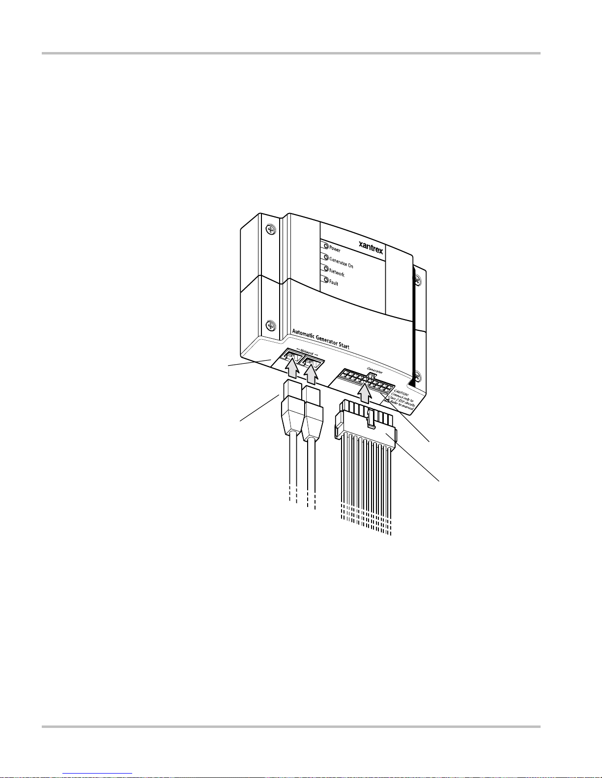
Front and Bottom Panel
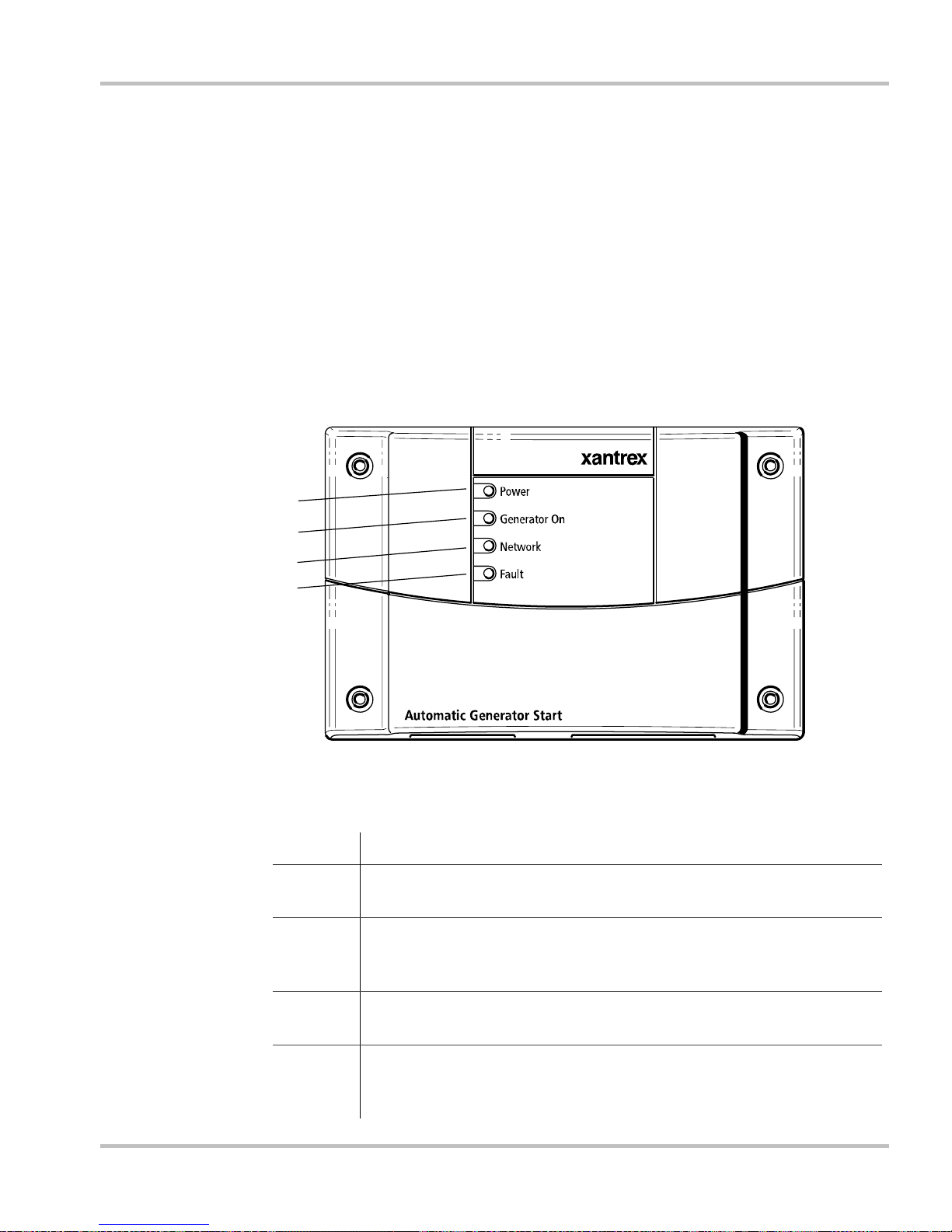
Indicator lights Four lights on the front panel indicate the operating status and network
status of the Auto Gen Start.
Connectors Two network ports on the bottom panel connect the Auto Gen Start to the
Xanbus system. A 20-contact pluggable connector (also on the bottom
panel) allows the Auto Gen Start to connect to the generator’s starting
circuitry, thermostats and external switches. See “B ottom panel” on
page 1–6.
Front panel
Figure 1-1
Auto Gen Start front panel
Table 1-1
Front panel features
Feature Description
1
Power light (green) indicates the Auto Gen Start
is receiving
network power.
2 Generator On light (green) indicates the generator is running.
This light turns on when the generator run signal is active. See
“Important” on page 2–24.
3
Network light (green) indicates the Auto Gen Start
is
communicating with other Xanbus-enabled devices.
4 Fault light (red) indicates an Auto Gen Start fault has occurred.
See “Troubleshooting” on page 5–1 for information about Auto
Gen Start faults.
1
2
3
4
Page 20
Introduction
1–6 975-0082-01-01
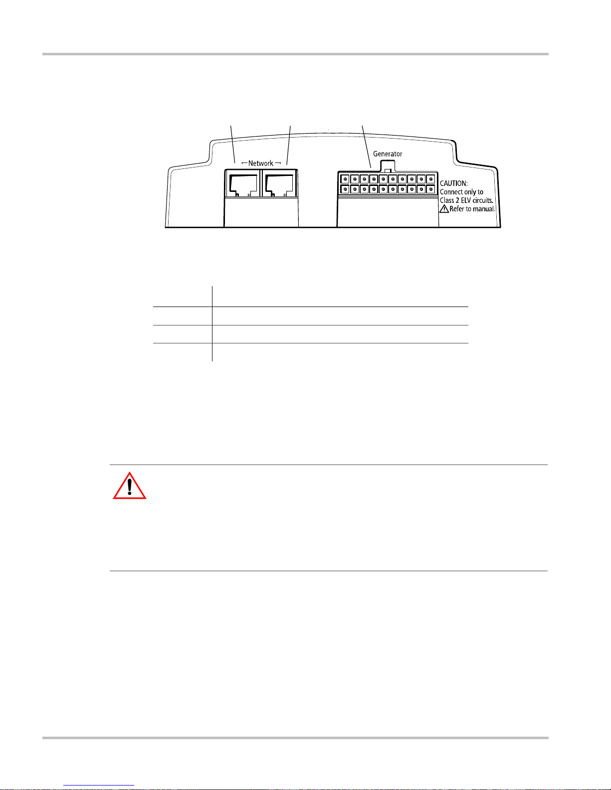
Bottom panel
Network
connectors
Each network port can accept an eight-pin RJ45 plug attached to a CAT 5
cable. Depending on your installation, you may need to use one or both
the network connectors. For more information, see the Xanbus System
Installation Guide.
20-contact
connector
The 20-contact connector allows you to plug in a wiring harness that
connects the Auto Gen Start to a generator and thermostats. The wiring
harness also provides lines for connecting external generator shutd own
sensors or switches and external generator on/off controls.
Figure 1-2
Auto Gen Start bottom panel
Table 1-2
Auto Gen Start connection points
Feature Description
1 Network port (eight-pin RJ45)
2 Network port (eight-pin RJ45)
3 20-contact generator connector
1
23
CAUTION: Equipment Damage
Connect the Auto Gen Start only to other Xanbus compatible devices.
Although the cabling and connectors used in this network system are the same as
Ethernet connectors, this network is not an Ethernet system. Equipment
damage may result from attempting to connect these two different systems.
Page 21
Xanbus System Components
975-0082-01-01 1–7
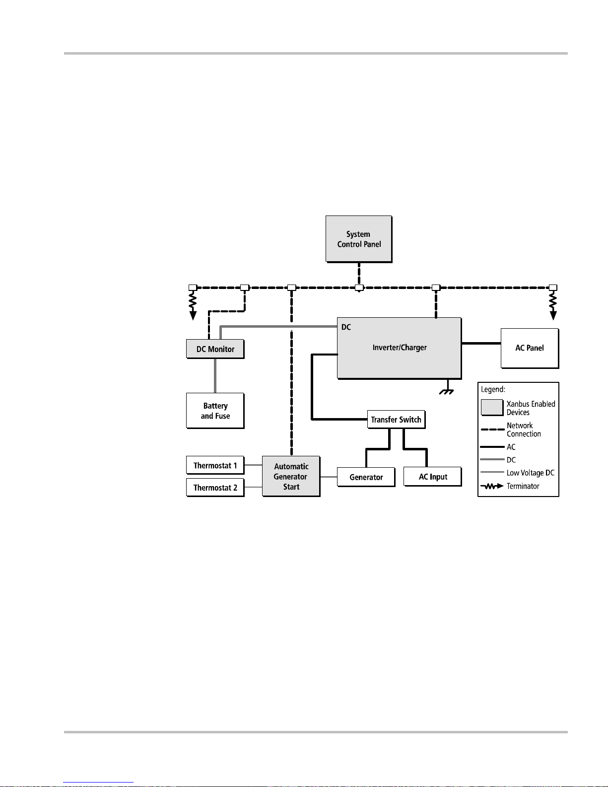
Xanbus System Components
System
description
The Xantrex Xanbus system includes the Auto Gen Start and other
Xanbus-enabled devices. Each device interacts and communicates with
the other devices, creating a power system that can be precisely
configured to your needs.
Network
diagram
Figure 1-3 shows the Auto Gen Start as part of a Xanbus system.
Figure 1-3
Xanbus system diagram
AC In
AC Out
Page 22

1–8
Page 23

2
Installation
Chapter 2 contains information and procedures to
install the Auto Gen Start.
This chapter will help you prepare to install the Auto
Gen Start by providing:
• a summary of the tasks involved
• a list of materials and tools required
• recommendations for choosing an installation
location
This chapter then provides procedures for mounting
the Auto Gen Start, as well as guidelines for
connecting it to:
• a generator
• thermostats
• the System Control Panel and other Xanbusenabled devices
Page 24

Installation
2–2 975-0082-01-01
Preparing an Installation
Before you install the Auto Gen Start, you must consider how and where
the unit will be mounted, and plan the connection routes between the
Auto Gen Start, the generator, thermostats and the control panel.
Tools and materials required
Before beginning an installation, you will need the following tools and
materials:
❐ Mounting template (supplied)
❐ Wiring harness (Xantrex part number 809-0917, supplied)
❐ Four #6 screws, 1 1/4 inch (sup plied)
❐ #16 or #18 AWG wire (see “Wire size and length” on page 2–7)
❐ Xantrex network cables or equivalent
❐ Network terminators (if required)
❐ Phillips screwdriver
❐ Wire cutters
❐ Wire strippers
Page 25
Preparing an Installation
975-0082-01-01 2–3
Choosing a location
The Auto Gen Start should be installed in a location that meets the
following requirements:
Routing the connections
Dry
The unit is intended for use in a dry location. The Auto Gen
Start
complies with UL458 Marine Supplement drip-test
requirements, but the location should be as dry as possible.
Cool
The Auto Gen Start
operates between -4 and 122 °F (-20 and
50 °C).
Safe
The Auto Gen Start
is not ignition protected. Do not install it in
areas requiring ignition-protected equipment, such as
compartments housing gasoline engines.
Close to
generator
Avoid excessive wire lengths and use the recommended wire
lengths and sizes (see “Wire size and length” on page 2–7). It is
more important for the Auto Gen Start
to be close to the
generator than close to the inverter, although for safety reasons,
the Auto Gen Start should not be installed in the same
compartment as a gasoline-powered generator.
WARNING: Explosion hazard
This equipment is not ignition protected. To prevent fire or explosion, do not
install the Auto Gen Start in compartments containing flammable materials or in
locations that require ignition-protected equipment. This includes any space
containing gasoline-powered machinery, fuel tanks, as well as joints, fittings, or
other connections between components of the fuel system.
Follow all relevant instructions exactly before installi ng or using your Auto Gen
Start.
WARNING: Shock and energy hazards
Before making any connections to the generator, ensure that the generator’s
starter is disabled and the generator ’s start battery is disconnected.
Page 26
Installation
2–4 975-0082-01-01
Because the Auto Gen Start will be part of a Xanbus system, you must
consider how to route two types of connections:
• connections to the generator, thermostats, and other external devices
and switches, using the 20-contact connector and wiring harness.
• connections to other Xanbus-enabled devices, using network cables.
For information on designing and installing the network, see the Xanbus
System Installation Guide.
Installing the Auto Gen Start
After selecting your tools and choosing the best location and connection
routes for your installation, you are now ready to mount the Auto Gen
Start and connect it to the generator, thermostats and System Control
Panel.
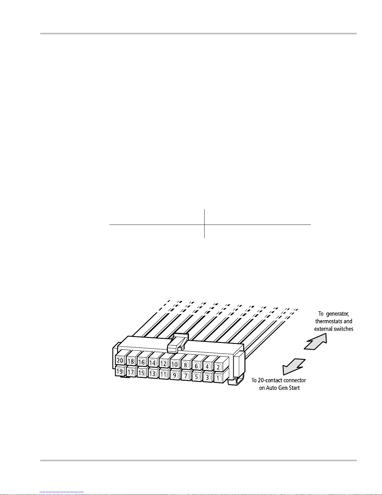
Figure 2-1
Auto Gen Start external connections
Wiring harness (connection
to generator, thermostats,
and external switches)
Network cables to other
Xanbus-enabled devices
20-contact
connector
Network ports
Page 27

Installing the Auto Gen Start
975-0082-01-01 2–5
Installation
overview
Installing the Auto Gen Start involves the following steps:
1. Mounting the unit.
2. Connecting the wiring harness to:
• the generator (page 2–9)
• thermostats (optional) (page 2–23)
• external shutdown switch (optional) (page 2–23)
• external on/off switch and LED (optional) (page 2–23)
3. Connecting the wiring harness to the 20-contact connector on the
Auto Gen Start.
4. Connecting the Auto Gen Start to the System Control Panel and other
network-enabled devices (page 2–26).
Mounting the unit
The Auto Gen Start is to be mounted vertically on a wall with the
connectors facing downwards.
To mount the Auto Gen Start:
1. Hold the unit flush and square against the wall, panel or horizontal
surface.
• If your mounting surface requires you to pre-drill holes for the
screws, use the supplied mounting template to mark, then drill,
four holes.
2. With a Phillips screwdriver and the supplied #6 screws, secure each
corner of the Auto Gen Start to the mounting surface.
Note: Because each installation varies according to the location, the type of
generator, and the overall complexity of the Xanbus system, these instructions
can offer only general guidelines for the many installation options available.
WARNING: Shock hazard
Before installing the Auto Gen Start as part of a pre-existing Xanbus system, put
the system in Safe mode in order to disable the electrical operation of networked
devices. See “Changing System Modes” on page 4–6.
Page 28
Installation
2–6 975-0082-01-01
Wiring to the 20-contact connector
ELV circuits ELV (Extra-Low Voltage) circuits have an open-circuit voltage of not
more than 30 V
rms
or 42.2 VDC or peak, and are therefore not a shock
hazard.
Class 2 circuits As per the US National Electrical Code (NEC) and the Canadian
Electrical Code (CEC), available power in Class 2 circuits is limited to
100 VA, usually by current limiting by means of overcurrent protection or
series resistance. The current is limited to 5 A for circuits with opencircuit voltage of 20 V, and to I=100/V
oc
for circuits with open circuit
voltage between 20 V and 30 V.
The advantage of using Class 2 circuits for installing the Auto Gen Start is
that Class 2 circuits don’t have to follow the Class 1 wiring rules
(requiring the use of conduit and wiring boxes, et cetera) that apply
elsewhere in the applicable codes.
Circuit
limitations
The relay contacts in the Auto Gen Start are rated at 5 A maximum and all
circuits on the 20-contact connector are rated at 30 V maximum.
Ensure that all circuits connected to the 20-contact connector obey the
following limits:
WARNING: Shock hazard
All installation wiring should be performed by a qualified installer or electrician.
WARNING: Fire, shock, and energy hazards
The 20-contact connector is intended for connection to Class 2 ELV (Extra Low
Voltage) circuits on ly. Do not exceed the circuit limitations specified in the
following section.
Open circuit voltage (Voc)
30 V maximum
Overcurrent protection
(fuse size for open circuit voltage up to 20 V)
5 A maximum
Overcurrent protection
(fuse size for open circuit voltage from 20 V to
30 V)
5 A to 3.33 A
(100/V
oc
amps maximum)
Page 29
Installing the Auto Gen Start
975-0082-01-01 2–7
Wiring harness Connections to the generator, thermostats, and external on/off switches
are made using a wiring harness that plugs into the 20-contact connector
(see Figure 2-1). The wires on the wiring harness can be extended to meet
installation requirements. When extending the wire harness, ensure that
the extension wires are the same color as the wires on the harness.
To install the Auto Gen Start using the wiring harness:
1. Connect each wire on the harness to its intended wire or contact on
the generator, thermostats, or external switches.
2. Plug the harness into the connector on the bottom panel of the Auto
Gen Start.
Wire
identification
Each wire on the harness is identified by a number and a color. The wire
numbers are shown in Figure 2-2 and their colors and functions are
described in Table 2-1.
Wire size and
length
Required wire sizes for the external connections to the wiring harness are:
When planning the routing for external connections, ensure that wire
lengths are sufficient to plug the wiring harness into the Auto Gen Start
once all the external connections are complete.
0–30 ft. (9 m) Over 30 ft. (9 m)
18 AWG 16 AWG
Figure 2-2
Auto Gen Start wiring harness
Page 30

Installation
2–8 975-0082-01-01
Table 2-1
Contact numbers and functions
Wire
number Function
Wiring harness
wire color
1 Thermostat 1 input Yellow
2 Thermostat 1 return Gray
3 Thermostat 2 input Orange
4 Thermostat 2 return Gray
5 External shutdown input White/Black
6 External shutdown return Gray
7 External manual on input White/Green
8 External manual off input White/Red
9 External On/Off LED Indicator output White/Blue
10 Constant 12/24 V B+ (battery positive) for
External On/Off/LED Indicator
Red
11 External On/Off/LED Indicator return (connected
internally to wire number 13)
Black
12 Gen e rator run signal (switched B+) sense input Violet
13 Gen erator run signal (switched B+) sense return
(generator battery negative)
Black
14 Relay 1 (Generator run/stop ) Normal ly open
contact
Blue
15 Relay 1 (Generator run/stop) Normally closed
contact
White/Violet
16 Relay 1 (Generator run/stop) Common contact Gray
17 Relay 2 (Generator start) Normally open contact White
18 Relay 2 (Generator start) Common contact Gray
19 Relay 3 (Preheat/cooldown) Normally open
contact
Brown
20 Relay 3 (Preheat/cooldown) Common contact Gray
Page 31

Installing the Auto Gen Start
975-0082-01-01 2–9
Connecting the generator
To connect the Auto Gen Start to a generator, you must identify the start
wiring configuration of the generator you want to use. Generators must be
auto-start capable, and generators equipped with remote operation
connections are ideal.
If the generator is equipped for remote operation, you must examine the
wiring of the remote cable and connector (or read your generator’s
documentation, if available) and identify the following wires:
•Ground
•Start
•Stop
• Generator run signal, also known as the Hour Meter or Switched B+
(battery positive)
Wiring
requirements
To wire the Auto Gen Start to the generator, you need #16 or #18 AWG
wire connected between contacts 12 to 20 on the wiring harness. How
many of these wires you connect and in which combinatio n depends on
your generator type.
Generator types The Auto Gen Start has 13 preset generator configurations, or “Gen
T ypes” (see “Gen Type” on page 3–16). T o ensure that the Auto Gen S tart
is compatible with your generator’s starting circuitry, you must select
your type of generator from the Auto Gen Start menu on the System
Control Panel after completing the installation.
This section describes the generator configurations and provides diagrams
for connecting the wiring harness to the generator’s start wiring.
Important:
You can only change “Gen Type” after you have put the system
into Safe mode. See “Changing System Modes” on page 4–6.
Note: For an explanation of the terminology used in the following section,
refer to Appendix B, “Generator Auto Start Requirements and Types”. For
more information about Auto Gen Start internal relay activity and timing, see
Appendix C, “Relay Timing”.
Page 32

Installation
2–10 975-0082-01-01
Type 1
Type 1 is a three-wire GlowStop configuration recommended for “threewire” generators with glow plugs that need to be operated before a start is
attempted.
Figure 2-3
Type 1 connection diagram
Table 2-2
Type 1 relay and timing preset configurations
Relay 1 mode
GlowStop
Relay 3 mode
No function
Gen Run signal hold time
0.5 s
Preheat time
20 s
Preheat to crank delay
1 s
Crank time
15 s
Crank retry time
30 s
Shutdown bypass time
0 s
Start tries
3
18
17
START
16
14
13
12
GEN RUN SIGNAL
GROUND
STOP/PREHEAT
Relay 1
Relay 2
5A fuse
5A fuse
AGS wiring harness Generator wires
Complete overcurrent protection
not shown. Refer to page 2–6.
Page 33

Installing the Auto Gen Start
975-0082-01-01 2–11
Type 2
Type 2 is a three-wire GlowStop configuration recommended for “threewire” generators that don’t require a dedicated preheat signal, such as
Onan generators. In this configuration, the start signal is applied for
longer because the generator does its own preheat and cranking while the
start signal is applied.
Figure 2-4
Type 2 and Type 12 connection diagram
Table 2-3
Type 2 relay and timing preset configurations
Relay 1 mode
GlowStop
Relay 3 mode
No function
Gen Run signal hold time
0.5 s
Preheat time
0 s
Preheat to crank delay
0 s
Crank time
30 s
Crank retry time
40 s
Shutdown bypass time
0 s
Start tries
3
18
17
START
16
14
13
12
GEN RUN SIGNAL
GROUND
STOP
Relay 1
Relay 2
5A fuse
5A fuse
AGS wiring harness
Generator wires
Complete overcurrent protection
not shown. Refer to page 2–6.
Page 34

Installation
2–12 975-0082-01-01
Type 3
Type 3 is a three-wire GlowStop with shutdown bypass configuration.
The configuration shown in Figure 2-5 uses a shutdown by pass output to
temporarily disable the generator’s low oil pressure shutdown
functionality during cranking. (Generators with this functionality often
have a manual means of disabling it during cranking.)
Figure 2-5
Type 3 connection diagram
Table 2-4
Type 3 relay and timing preset configurations
Relay 1 mode
GlowStop/Shutdown bypass
Relay 3 mode
Preheat/Shutdown bypass
Gen Run signal hold time
0.5 s
Preheat time
20 s
Preheat to crank delay
0 s
Crank time
15 s
Crank retry time
30 s
Shutdown bypass time
10 s
Start tries
3
PREHEAT
BYPASS SHUTDOWN
STOP
14
13
12
GEN RUN SIGNAL
GROUND
18
17
START
16
Relay 1
Relay 2
5A fuse
5A fuse
Generator wireAGS wiring harness wire
Complete overcurrent protection
not shown. Refer to page 2–6.
Page 35

Installing the Auto Gen Start
975-0082-01-01 2–13
Type 4
Type 4 is a three-wire StartStop configuration that uses relay 3 to provide
the preheat signal for Generac’s Guardian Gas generators.
Figure 2-6
Type 4, Type 5 and Type 13 connection diagram
Table 2-5
Type 4 relay and timing preset configurations
Relay 1 mode
StartStop
Relay 3 mode
Preheat
Gen Run signal hold time
10 s
Preheat time
60 s
Preheat to crank delay
5 s
Crank time
15 s
Crank retry time
15 s
Shutdown bypass time
0 s
Start tries
3
18
17
START
16
14
13
12
GEN RUN SIGNAL
GROUND
STOP/PREHEAT
20
19
FUEL PRIME (PREHEAT)
12V GENERATOR BATTERY +
Relay 1
Relay 3
Relay 2
5A fuse
5A fuse
5A fuse
Generator wiresAGS wiring harness
Complete overcurrent protection
not shown. Refer to page 2–6.
Page 36

Installation
2–14 975-0082-01-01
Type 5
Type 5 is a three-wire StartStop configuration that uses relay 3 to provide
the preheat signal for Generac’s Gua rdian Diesel generators.
The wiring diagram for a Type 5 configuration is the same as a Type 4
(see Figure 2-6).
Table 2-6
Type 5 relay and timing preset configurations
Relay 1 mode
StartStop
Relay 3 mode
Preheat
Gen Run signal hold time
2 s
Preheat time
15 s
Preheat to crank delay
2 s
Crank time
15 s
Crank retry time
15 s
Shutdown bypass time
0 s
Start tries
3
Page 37

Installing the Auto Gen Start
975-0082-01-01 2–15
Type 6
Type 6 is a three-wire GlowStop configuration that has a normally closed
Run/Stop contact. This generator type is intended for Yamaha generators.
Type 7
Type 7 will work with both two-wire and three-wire run mode
configurations that require a preheat signal before cranking, such as
Generac Backup/Renewable generators. This Gen Type setting is suitable
for generators with an automatic engine cranking control system (twowire) and generators that require that the Auto Gen Start control their
starter separately (three-wire).
Figure 2-7
Type 6 connection diagram
Table 2-7
Type 6 relay and timing preset configurations
Relay 1 mode
GlowStop
Relay 3 mode
No function
Gen Run signal hold time
0.5 s
Preheat time
10 s
Preheat to crank delay
1 s
Crank time
15 s
Crank retry time
30 s
Shutdown bypass time
0 s
Start tries
3
18
17
START
16
15
13
12
GEN RUN SIGNAL
GROUND
PREHEAT14
STOP
Relay 2
Relay 1
5A fuse
5A fuse
5A fuse
Generator wiresAGS wiring harness
Complete overcurrent protection
not shown. Refer to page 2–6.
Page 38

Installation
2–16 975-0082-01-01
Figure 2-8
Type 7, Type 8, and Type 11 connection diagram (two-wire)
Figure 2-9
Type 7 and Type 8 connection diagram (three-wire)
Table 2-8
Type 7 relay and timing preset configurations
Relay 1 mode
Run
Relay 3 mode
No function
Gen Run signal hold time
0.5 s
Preheat time
20 s
Preheat to crank delay
1 s
Crank time
15 s
Crank retry time
30 s
Shutdown bypass time
0 s
Start tries
3
16
14
13
12
GEN RUN SIGNAL
GROUND
RUN
Relay 1
5A fuse
AGS wiring harness Generator wires
Complete overcurrent protection
not shown. Refer to page 2–6.
18
17
START
16
14
13
12
GEN RUN SIGNAL
GROUND
RUN
Relay 1
Relay 2
5A fuse
5A fuse
AGS wiring harness Generator wire s
Complete overcurrent protection
not shown. Refer to page 2–6.
Page 39

Installing the Auto Gen Start
975-0082-01-01 2–17
Type 8
Type 8 will work with both two-wire and three-wire run mode
configurations and is intended for Northern Lights and Fisher Pa nda
generators. T ype 8 is identical to Type 7 except that it provides no preheat
signal before cranking. See Figure 2-8 and Figure 2-9 for wiring
diagrams.
Table 2-9
Type 8 relay and timing preset configurations
Relay 1 mode
Run
Relay 3 mode
No function
Gen Run signal hold time
0.5 s
Preheat time
0 s
Preheat to crank delay
0 s
Crank time
15 s
Crank retry time
30 s
Shutdown bypass time
0 s
Start tries
3
Page 40

Installation
2–18 975-0082-01-01
Type 9
Type 9 is a StartStop mode configuration with shutdown bypass
functionality on relay 3. This configuration is intended for Westerbeke
generators.
Figure 2-10
Type 9 connection diagram
Table 2-10
Type 9 relay and timing preset configurations
Relay 1 mode
StartStop
Relay 3 mode
Shutdown Bypass
Gen Run signal hold time
0.5 s
Preheat time
0 s
Preheat to crank delay
0 s
Crank time
15 s
Crank retry time
30 s
Shutdown bypass time
5 s
Start tries
3
18
17
START
16
14
13
12
GEN RUN SIGNAL
GROUND
STOP
20
19
PREHEAT & SHUTDOWN BYPASS
12V GENERATOR BATTERY +
Relay 1
Relay 3
Relay 2
5A fuse
5A fuse
5A fuse
AGS wiring harness Generator wires
Complete overcurrent protection
not shown. Refer to page 2–6.
Page 41

Installing the Auto Gen Start
975-0082-01-01 2–19
Type 10
Type 10 is a StartStop mode configuration with no preheat signal or
shutdown bypass functionality.
Figure 2-11
Type 10 connection diagram
Table 2-11
Type 10 relay and timing preset configurations
Relay 1 mode
StartStop
Relay 3 mode
No function
Gen Run signal hold time
0.5 s
Preheat time
0 s
Preheat to crank delay
0 s
Crank time
15 s
Crank retry time
30 s
Shutdown bypass time
0 s
Start tries
3
18
17
START
16
14
13
12
GEN RUN SIGNAL
GROUND
STOP
Relay 1
Relay 2
5A fuse
5A fuse
AGS wiring harness Generator wires
Complete overcurrent protection
not shown. Refer to page 2–6.
Page 42

Installation
2–20 975-0082-01-01
Type 11
Type 11 is a two-wire run mode configuration intended for Kohler
generators. It requires only two wires and one relay to control the
generator. Relay 1 closes momentarily once to start the generator, and
closes momentarily again to stop the generator.
The wiring diagram for a Type 11 configuration is the same as a two-wire
Type 7 configuration. See Figure 2-8.
Table 2-12
Type 11 relay and timing preset configurations
Relay 1 mode
MomentaryRun
Relay 3 mode
No function
Gen Run signal hold time
0.5 s
Preheat time
0 s
Preheat to crank delay
0 s
Crank time
10 s
Crank retry time
15 s
Shutdown bypass time
0 s
Start tries
3
Page 43

Installing the Auto Gen Start
975-0082-01-01 2–21
Type 12
Type 12 is a three-wire GlowStop configuration recommended for “threewire” generators that don’t require a dedicated preheat signal, such as
Onan propane generators. In this configuration, the start signal is applied
for longer because the generator does its own preheat and cranking while
the start signal is applied.
The wiring diagram for a Type 12 configuration is the same as a threewire Type 2 configuration. See Figure 2-4.
Table 2-13
Type 12 relay and timing preset configurations
Relay 1 mode
GlowStop
Relay 3 mode
No function
Gen Run signal hold time
4 s
Preheat time
0 s
Preheat to crank delay
0 s
Crank time
30 s
Crank retry time
40 s
Shutdown bypass time
0 s
Start tries
3
Page 44

Installation
2–22 975-0082-01-01
Type 13
Type 13 is a three-wire PulseStop configuration that uses relay 3 to
provide the preheat signal for PowerTech’s Diesel generators. With this
generator type, there will be a delay between the generator turning off and
the Auto Gen Start recognizing that the generator is off.
The wiring diagram for a Type 13 configuration is the same as a Type 4
(see Figure 2-6).
Table 2-14
Type 13 relay and timing preset configurations
Relay 1 mode
PulseStop
Relay 3 mode
Preheat
Gen Run signal hold time
5 s
Preheat time
15 s
Preheat to crank delay
2 s
Crank time
15 s
Crank retry time
15 s
Shutdown bypass time
0 s
Start tries
3
Page 45

Installing the Auto Gen Start
975-0082-01-01 2–23
Connecting the thermostats (optional)
Wires 1, 2, 3, and 4 on the wiring harness can be connected to two
thermostats. Wires 1 (yellow) and 2 (gray) are intended for thermostat 1
and wires 3 (orange) and 4 (gray) are intended for thermostat 2.
These wires connect to 12/24 V output signals from the thermostats. You
can enable the Auto Gen Start to start the generator in response to these
signals. You cannot program your thermostats with the Auto Gen Start.
For specific information about thermostat wiring and where Auto Gen
Start connections should be made, please consult your thermostat
documentation or contact the thermostat manufacturer.
Connecting an external shutdown (optional)
The external shutdown input is a 12/24V input used to assure that the
Auto Gen Start keeps the generator off under conditions that may be
potentially hazardous. Wire 5 (white/black) and 6 (gray) on the wiring
harness are intended for an external switch or sensor (such as a moisture
detector, carbon monoxide detector or coach running signal) that
produces an active high 12V or 24V output.
Connecting an external manual on/off switch (optional)
The external manual on/off inputs (wires 7 and 8 on the wiring harness)
are intended for wiring to one or more remote on/off switches for starting
and stopping the generator manually. The other contact of the switch
should be connected to ground. In order for the Auto Gen Start to be able
to detect these switches, you must wire the positive of the generator
battery to the constant 12V/24V generator battery positive (wire 10 on the
Auto Gen Start wiring harness). See Figure 2-12.
Wire number Function Wiring harness wire color
1 Thermostat 1 input (12/24 V) Yellow
2 Thermostat 1 return (ground) Gray
3 Thermostat 2 input (12/24 V) Orange
4 Thermostat 2 return (ground) Gray
Wire number Function Wiring harness wire color
5 External shutdown input (12/24 V) White/Black
6 External shutdown return (ground) Gray
Page 46

Installation
2–24 975-0082-01-01
If your generator battery does not have the required voltage, any 12V or
24V power source will suit this purpose. If an alternate power source is
used, the negative of the power source must be connect to the other
contact of the switch.
Multiple control panels or simple contact closures can be wired to the
external manual on/off inputs. The Auto Gen Start detects if any of the
contacts close and will change its operating mode to External Manual On
or External Manual Off (for more information, see “AGS Mode” on
page 3–9). The Auto Gen Start turns the generator on or off according to
these inputs and the resulting operating mode change.
Unlike the Manual On or Manual Off operating modes you can enter by
using the System Control Panel, the External Manual On and External
Manual Off states are not affected by maximum generator run time (see
“Max Run Time” on page 3–29).
Connecting an external on/off LED
Wires 9 (White/Blue) and 11 (Black) on the wiring harness can be
connected to an LED or other light to accompany a remote external on/off
switch. This light turns on when the generator run signal is active to
visually indicate that the generator is running.
Wire number Function Wiring harness wire color
7 External manual on input White/Green
8 External manual off input White/Red
9 External On/Off LED Indicator
output
White/Blue
10 Constant 12/24 V B+ for
External On/Off/LED Indicator
Red
11 External On/Off/LED Indicator
return
Black
Important::
With some generators, the generator run signal becomes active
during the preheat stage, before the generator is actually running. In this case, the
external on/off LED (and the Generator On light on the Auto Gen Start) will turn
on during the preheat stage and remain on when the generator is running.
For some generators, these lights will also remain on for a period of time after the
generator has stopped.
Page 47

Installing the Auto Gen Start
975-0082-01-01 2–25
Connecting the wiring harness to the Auto Gen Start
After all the external connections have been wired to the wiring harness,
the connector on the wiring harness must be plugged into the 20-contact
connector on the Auto Gen Start.
To connect the wiring harness to the Auto Gen Start:
◆ With the click-tab on the wiring harness connector on top (facing
you), insert the wiring harness connector into the 20-contact
connector on the Auto Gen Start until the tab clicks into place.
Figure 2-12
External on/off switch and LED wiring diagram
START PUSH BUTTON
STOP PUSH BUTTON
12V OR 24V
EXTERNAL LED
EXTERNAL LED
GROUND
7
8
9
10
11
13
2K
2K
5K11
Page 48

Installation
2–26 975-0082-01-01
Connecting the control panel and other network-enabled devices
To connect the Auto Gen Start to a System Control Panel or another
network-enabled device, plug a Xantrex network cable or equivalent from
another device into one of the network connectors on th e bo ttom p ane l of
the Auto Gen Start. See Figure 2-1 on page 2–4.
If the Auto Gen Start is being installed on an existing Xanbus system, the
system must first be put into Safe mode. See “Changing System Modes”
on page 4–6.
Depending on the layout of the Xanbus system, you have the following
options for the other network connector on the Auto Gen Start:
• A second network cable (in a “daisy-chain” network layout)
• A network terminator (in a “daisy chain” network layout where the
Auto Gen Start is the last device at one end of the network)
• Nothing (in a multi-drop backbone layout)
Verifying power is available
When the Auto Gen Start has been installed properly, the Power and
Network indicator lights turn on.
If one or both lights are out, check the network connections and ensure
the network power supply is on.
CAUTION:
Equipment damage
Connect only to other Xanbus-enabled devices.
Although the cabling and connectors used in this network system are the same as
Ethernet connectors, this network is not an Ethernet system. Equipment
damage may result from attempting to connect these two different systems.
Page 49

3
Configuration
Chapter 3 contains information and procedures for
configuring the Automatic Generator Start. It describes
how you can view the Auto Gen Start menu on the
System Control Panel, and how you can change Auto
Gen Start settings using the System Control Panel.
Chapter 3 also discusses each Auto Gen Start setting by:
• Defining each setting.
• Listing the available values for each setting.
• Recommending when to use each setting.
• Describing the effect of changing each setting.
Page 50

Configuration
3–2 975-0082-01-01
Configuring the Auto Gen Start
The Auto Gen Start has a number of settings that you must configure to
ensure that the generator automatically starts and stops under the right
conditions and at the right time.
If your Auto Gen Start was pre-installed in your Xanbus system, it may
already be configured to work with your generator and network-enabled
power system. If this is the case, you may not have to configure any
settings other than the Generator mode (see page 3–9) and Quiet Time
(see page 3–11).
Using the System Control Panel
The Auto Gen Start is configured using the System Control Panel. You
can view all the available Auto Gen Start settings on the System Control
Panel screen.
The System Control Panel has four navigation buttons that you use to
move between screens and menus, highlight settings you want to change,
and select values for the Auto Gen Start to use.
See Figure 3-1 and Table 3-1 for the location and function of the
navigation buttons on the System Control Panel.
Figure 3-1
System Control P a nel
2134
Page 51

Configuring the Auto Gen Start
975-0082-01-01 3–3
Changing Auto Gen Start settings using the System Control Panel
If you need to change an Auto Gen Start setting, use the buttons on the
System Control Panel to perform three basic steps:
1. View the Select Device menu.
2. Select the Auto Gen Start from the Select Device menu.
3. Select and adjust a changeable setting on the Auto Gen Start menu.
Each of these three steps is described in detail in the following sections.
Viewing the Select Device menu
The Select Device menu is where you select a Xanbus-enabled device to
monitor or configure. The number of items on the Select Device menu
depends on how many devices are installed in your Xanbus system.
To view the Select Device menu:
◆ On the System screen (see Figure 3-2), press Enter.
Table 3-1
System Control Pa nel navigation buttons
Number Button Function
1 Enter • Confirms selection of a menu item
• Moves to the next screen
2 Up arrow • Scrolls up one line of text
• Increases a selected value
3 Down arrow • Scrolls down one line of text
• Decreases a selected value
4 Exit • Cancels selection of a menu item
• Returns you to the previous screen
Figure 3-2
System screen (example)
menu
Page 52

Configuration
3–4 975-0082-01-01
Viewing the Auto Gen Start menu
On the Select Device menu, select the Auto Gen Start to view and change
its settings.
To select the Auto Gen Start from the Select Device menu:
1. On the Select Device menu, use the down arrow button to highlight
Auto Gen Start.
2. Press Enter.
The Auto Gen Start menu appears.
Selecting and adjusting the changeable setting
On the Auto Gen Start menu, you can view and change Auto Gen Start
settings, and monitor generator starting activity.
Changeable settings are identified by the square brackets [ ] around the
values along the right side of the screen.
Important:
You can always identify the System screen by the menu arrow in
the bottom left corner of the screen. The menu arrow indicates the Enter button
on the System Control Panel, which you press to view the Select Device menu.
Figure 3-3
Selecting the Auto Gen Start
Figure 3-4
Auto Gen Start menu (basic menu shown)
Off
NotOn
[ManualOff]
[On]
Page 53

The Auto Gen Start Menu
975-0082-01-01 3–5
To select and adjust a changeable setting:
1. On the Auto Gen Start menu, use the up arrow or down arrow button
to highlight the setting you want to change.
2. Press Enter to highlight the current value of that changeable setting.
Some values appear with an asterisk (*) to identify them as the value
that was last set.
3. Use the up arrow or down arrow button to change the value. Hold a
button down to scroll through values quickly.
4. Press Enter to select the value.
5. If you have another setting to change, return to step 1.
Or
If you have no more settings to change, press Exit twice to return to
the System screen.
The Auto Gen Start Menu
The Auto Gen Start menu contains status information and settings. You
can display the Auto Gen Start menu in two formats: basic and advanced.
Basic menu The basic menu contains settings you may have to adjust routinely. The
System Control Panel shows the basic menu by default.
Advanced menu The advanced menu contains several sub-menus that include all items on
the basic menu, as well as additional configurable settings. These submenus are:
• AGS Triggers menu (see page 3–19).
• Generator Configuration menu (see page 3–28)
• Device Info screens (see page 3–35)
On the advanced menu you can also return to the ba sic menu format.
To view the advanced menu, see page 4–5.
Page 54

Configuration
3–6 975-0082-01-01
Figure 3-5
Auto Gen Start menu contents
Page 55

The Auto Gen Start Menu
975-0082-01-01 3–7
The Auto Gen Start basic menu
The Auto Gen Start basic menu lists settings you may have to adjust
routinely. The System Control Panel displays the Auto Gen Start basic
menu by default.
If you would like additional control over automatic generator starting,
you can find more settings on the Auto Gen Start advanced menu and
AGS Triggers menu (see “Auto Gen Start advanced menu” on page 3–18
and “AGS Triggers menu” on page 3–19). However, you may not have to
adjust these settings as part of regular operation.
The Auto Gen Start basic menu consists of the following items:
• “Gen Status” (status item)
• “Gen Trigger” (status item)
•“AGS Mode”
•“QT Enable”
• “QT Begin”
•“QT End”
•“Start SOC”
• “Start DCV”
•“Enable Temp1”
•“Enable Temp2”
• “Gen Type”
You can record any settings you change in the “User Settings” table on
page 3–36.
Page 56

Configuration
3–8 975-0082-01-01
Gen Status
Full name Generator Operating Status
Purpose “Gen Status” reports the current operating state of the generator. You
cannot adjust any “Gen Status” values.
Gen Trigger
Purpose “Gen Trigger” reports the source of the active generator start trigger. S tart
triggers can include battery voltage, inverter load, batte ry s ta te of charge,
thermostat triggers, or exercise period. You cannot adjust any “Gen
Trigger” values.
Value Description
On The generator is running.
Off The generator is not running.
Fault A fault condition exists. The Auto Gen Start is not controlling the
generator, or the Auto Gen Start has an internal fault. If the generator
is still running in a fault state, it may be stopped at the generator or by
one of the generator’s control panels. See “AGS Mode” and
“Troubleshooting” on page 5–1.
Value Description
NotOn Generator is not running
LowBattV Preset minimum battery voltage with associated time delay
CntctClosed Activated thermostat 1 or 2
BattSOCLow Preset minimum battery state of charge
ACIHigh Preset maximum inverter load current
Exercise Preset exercise period, exercise time, and exercise duration
ManualOn Started manually using System Control Panel
ExtOnviaAGS Started by external switch connected to Auto Gen Start
ExtOnviaGen Started by switch connected to generator
UnableToStop Aut o Gen Start has lost control of the running generator
Page 57

The Auto Gen Start Menu
975-0082-01-01 3–9
AGS Mode
Purpose “AGS Mode” is a changeable setting that controls the current operating
mode of the Auto Gen Start.
When to use You should change “AGS Mode” when you want to switch between
automatic generator control and manual generator control.
When the Xanbus system powers up all network-enabled devices, the
Auto Gen Start is in Manual Off mode. To enable automatic generator
starts, you must put the Auto Gen Start in Automatic mode.
Automatic If you would like the Auto Gen Start to start and stop the
generator automatically, select Automatic. The generator can start and
stop automatically in response to low battery voltage, low battery state of
charge (requires a DC Monitor in the Xanbus System), AC loads on the
inverter, thermostat triggers, or exercise time. Automatic mode also has a
Quiet Time feature, which prevents the generator from starting during
evening hours or other inconvenient times (see “QT Begin” on page 3–1 1,
“QT End” on page 3–13, and “Setting Quiet T ime” on page 4–3).
Automatic
mode overrides
When the Auto Gen Start is in Automatic mode, several settings and
conditions override automatic start and stop triggers. These overrides
include, in order of priority:
• Faults—The Auto Gen Start stops the generator when a fault occurs.
Value Description
Automatic Automatic mode
ManualOn Manual on mode
ManualOff Manual off mode (default mode)
WARNING: Fire and health hazard
Running a generator in an enclosed space produces potentially lethal exhaust
gases.
Before putting your RV or boat in storage, disable the Auto Gen Start by putting
the Xanbus system in Hibernate mode. Do not leave a generator connected to an
Auto Gen Start otherwise unattended.
Page 58

Configuration
3–10 975-0082-01-01
• External Shutdown—When the Auto Gen Start is connected to a
sensor or meter (a moisture detector, for example) wired to contacts 5
and 6 of the 20-contact connector, it stops the generator when the
device is activated. See “Connecting an external shutdown
(optional)” on page 2–23.
• External On/Off—The generator is manually started or stopped with a
switch wired to contacts 7 and 8 of the 20-contact connector. See
“Connecting an external manual on/off switch (optional)” on page 2–
23. When started with an external manual on/off switch, the generator
will not stop when it reaches Max Run Time. You must stop the
generator using the external manual on/off switch.
• Max Run Time—When the generator has exceeded its maximum run
time, a warning message will appear on the System Control Panel.
The Auto Gen Start will stop operating until you acknowledge the
warning by pressing Enter on the System Control Panel. See “Max
Run Time” on page 3–29.
• Manual On—The generator is started by selecting Manual On mode.
• Manual Off—The generator is stopped by selecting Manual Off
mode.
Manual On When you need to manually start the generator, select
Manual On. Selecting Manual On mode overrides the automatic start
settings and manually starts the generator. The generator will run until it
is manually stopped or until it reaches its Auto Gen Start-defined
Maximum Run Time (see “Max Run Time” on page 3–29).
Manual Off When you need to manually stop the generator, select
Manual off. Selecting Manual Off mode overrides the automatic stop
settings and manually stops the generator. You must select Manual Off to
stop the generator when the generator has been started manu ally. The
Auto Gen Start will not automatically start the generator again until you
select Automatic.
Important:
The Auto Gen Start mode must be set to Manual Off before you
change any start trigger parameters.
Page 59

The Auto Gen Start Menu
975-0082-01-01 3–11
QT Enable
Full name Quiet Time Enable
Purpose “QT Enable” enables or disables the Quiet Time functionality of the Auto
Gen Start.
“QT Enable” applies only when the Auto Gen Start is in Automatic mode.
When to use When you need to use the Auto Gen Start Quiet Time feature, set “QT
Enable” to On, then check or reset the times you have set for “QT Begin”
and “QT End”.
When you have no preferences or restrictions for when the generator
should run, set “QT Enable” to Off.
Outcomes Selecting On enables the Quiet Time feature. If the Auto Gen Start is in
Automatic mode, the Auto Gen Start stops and starts the generator
according to the times you have set for “QT Begin” and “QT End”.
Selecting Off disables the Quiet Time feature. The Auto Gen Start will
ignore the times you have set for “QT Begin” and “QT End”. If the Auto
Gen Start is in Automatic mode, the Auto Gen St art starts and stops the
generator at any time of the day or night in response to battery voltage,
battery state of charge, inverter load, thermostat triggers, and exercise
time.
QT Begin
Full name Quiet Time Begin
Purpose “QT Begin” is a changeable setting that defines the start of quiet time.
This setting also requires you to set “QT End”.
When to use “QT Begin” functions only if the Auto Gen Start is in Automatic mode.
Value Description
On, Off Enable or disable the Quiet Time functionality.
Value Description
12:00AM to 11:59PM
(12-hour clock)
00:00 to 23:59
(24-hour clock)
At the time you set for “QT Begin” the generator will
stop (if it is running) and not be able to start again
until the time you set for “QT End”. It ignores all
automatic start triggers during the time period
between “QT Begin” and “QT End”.
Page 60

Configuration
3–12 975-0082-01-01
Use the Quiet Time feature to ensure that the generator will not run during
the night, or to comply with “Quiet Time” guidelines at RV parks and
campgrounds.
To use the Auto Gen Start Quiet Time feature, first set “QT Enable” to
On, then set two times of the day or night (a Quiet Time Begin time and a
Quiet Time End time) to define a time int erval during which the generator
will not run.
To disable the Quiet Time feature, set “QT Enable” to Off.
Time zone When travelling between time zones, ensure that you set the clock on the
System Control Panel to your correct local time. Otherwise, your quiet
time settings will come into effect too early or too late.
Battery drain Quiet Time prevents the automatic starting of the generator regardless of
battery condition.
If you need to set a quiet time that lasts overnight, be aware that overnight
battery drain can be significant. Because you may need to use an inverter
and batteries to supply AC power during quiet time, be careful to
conserve battery power. Minimize the use of interior lights and set
thermostat temperature lower to prevent the furnace from coming on at
night during cool weather. Set thermostats higher to prevent air
conditioning coming on at night during warm weather.
Outcomes Sometimes automatic start or automatic stop triggers may overlap with
the beginning and end of quiet time. Three different quiet time scenarios
affect when the generator stops and starts.
1. If quiet time begins after the Auto Gen Start has started the generator,
the generator will stop. If the condition that started the generator is
still present when quiet time ends, the generator will restart.
2. If a condition that requires starting the generator occurs during quiet
time, the Auto Gen Start will ignore it until quiet time ends. If the
condition still exists at the end of quiet time (after the time you set for
“QT End”), the Auto Gen Start will start the generator.
3. If the running generator stops when quiet time begins and a condition
that requires stopping the generator occurs during quiet time, the
generator will not restart when quiet time ends.
Page 61

The Auto Gen Start Menu
975-0082-01-01 3–13
QT End
Full name Quiet Time End
Purpose “QT End” is a changeable setting that defines the end of quiet time.
This setting also requires you to set “QT Begin”.
When to use “QT End” functions only if the Auto Gen Start is in Automatic mode.
For more information about when to use “QT End” and the Auto Gen
Start Quiet Time feature, see “QT Begin” on page 3–11.
Start SOC
Full name Start Battery Charge
Purpose “Start SOC” is a changeable setting that allows the Auto Gen Start to start
the generator when the battery bank capacity falls to a certain percentage.
This setting requires you to set “Stop SOC” also (see page 3–19).
When to use Discharging deep cycle RV or marine batteries below 50% capacity
shortens their useful life. Correctly configuring the Auto Gen Start’s
“Start SOC” setting can help protect your batteries from repeated overdischarge.
In Automatic mode, the Auto Gen Start will start the generator to rechar ge
your batteries if the batteries’ state of charge is less than or equal to the
“Start SOC” setting.
Value Description
12:00AM to 11:59PM
(12-hour clock)
00:00 to 23:59
(24-hour clock)
At the time you set for
“QT End” the Auto Gen
Start will be able to automatically start the
generator again. If a start trigger has occurred
during quiet time and is still active, the generator
will start immediately after quiet time ends.
Values Default
Off, 40% to 90% (increments of 5%) Off (disabled)
Important:
To use the “Start SOC” setting, the Auto Gen Start requires
accurate battery monitoring and state of charge information from the Xantrex DC
Monitor. This menu item will not appear if a DC Monitor is not installed.
Page 62

Configuration
3–14 975-0082-01-01
State of charge
information
When a DC Monitor is installed, you can monitor the batteries’ state of
charge on the System screen or inverter/charger menu.
Outcomes If you set “Start SOC” too high, the generator will start more frequently
than is convenient.
If you set “Start SOC” too low, your batteries may be damaged by
repeated cycles of excessive discharge. The generator running time
necessary to charge the batteries may exceed the Generator Run Max
Time, and use too much fuel in the process.
Start DCV
Full name Starting Battery Voltage—30 seconds
Purpose “Start DCV” is a changeable setting that enables the Auto Gen Start to
start the generator whenever the battery voltage reaches a pre-set voltage
for longer than 30 seconds. You can also select the desired battery voltage
with this setting.
The Auto Gen Start will stop the generator when the battery voltage has
risen to the Stopping Battery voltage (see “StopBattV” on page 3–22), or
when the batteries have been recharged to the Absorption or Float stage.
This setting requires you to set either “StopBattV”, or a Stop at Charge
Stage setting (see “Stop Float” on page 3–26 and “Stop Absorb” on
page 3–25).
When to use If the Auto Gen Start is set to Automatic mode, then the Auto Gen Start
will start the generator when the system battery voltage (as measured by
the inverter/charger or DC Monitor) falls below the “Start DCV” setting
for the selected delay period.
You can use the “Start DCV” setting when there is no accurate, reliable
battery state of charge monitoring available, such as from the Xantrex DC
Monitor.
Battery voltage
information
During normal operation, battery voltage can be monitored from the
System screen or on the inverter/charger menu.
Values Default
Off, 4.0V to 60.0V (increments of 0.1V) 11.3V
Page 63

The Auto Gen Start Menu
975-0082-01-01 3–15
Whenever the generator starts automatically in response to “Start DCV”,
it will stop when the battery voltage reaches the Stop Battery Voltage
(“StopBattV”) setting. If you have enabled “Stop Float” or “Stop
Absorb”, the generator will stop when the Absorption or Float stages of
the battery charging have begun.
Outcomes If you set “Start DCV” too high, the generator will start more frequently
than is convenient.
If you set “Start DCV” too low, your batteries may be damaged by
repeated cycles of excessive discharge. The generator running time
necessary to charge the batteries may exceed “Max Run Time”, and use
too much fuel in the process.
Enable Temp1
Full name Enable Thermostat 1.
Purpose “Enable Temp1” is a changeable setting for starting the generator in
response to a signal from a thermostat. With “Enable Temp1” set to On,
the Auto Gen Start will start the generator to help power the furnace or the
air conditioner.
When to use Enable this setting if you have thermostats that control an air conditioning
system with high power requirements.
Outcomes If you enable this setting, the generator will start in response to a signal
from the thermostat. Everything related to setting the temperature at
which the air conditioning system comes on must be done on the
thermostat. There are no thermostat temperature settings on the Auto Gen
Start or the System Control Panel.
If you disable this setting, your air conditioning system will operate
without automatic generator assistance. To operate your air conditioner,
you will need to start the generator manually, or connect to another AC
input source.
Values Default
On, Off Off (disabled)
Page 64

Configuration
3–16 975-0082-01-01
Enable Temp2
Full name Enable Thermostat 2.
Purpose “Enable Temp2” is intended to be used when the Auto Gen Start is
connected to a second thermostat. All information and procedures for
“Enable Temp1” also apply for “Enable Temp2”.
Gen Type
Full name Generator type
Purpose “Gen T ype” is a changeable setting for selecting the starting requirements
of your generator . The st arting requirements determine how the Auto Gen
Start must be wired to the generator’s starting system. For more
information, see “Connecting the generator” on page 2–9 or Appendix B.
Values Default
On, Off Off (disabled)
Important:
You can only change “Gen Type” after you have put the system
into Safe mode. See “Changing System Modes” on page 4–6.
Option
Description
Configuration Mode
Type 1 General GlowStop
Type 2 Onan Diesel (Default) GlowStop with no preheat
Type 3 General GlowStop with shutdown bypass
Type 4 Guardian/Generac Gas StartStop with Relay 3 prime
Type 5 Guardian/Generac Diesel StartStop with Relay 3 preheat
Type 6 Yamaha GlowStop with normally closed
RunStop contact
Type 7 Generac Backup/
Renewable
Run with preheat
Type 8 Northern Lights and Fisher
Panda
Run with no preheat
Type 9 Westerbeke StartStop with Relay 3 preheat and
shutdown bypass
Page 65

The Auto Gen Start Menu
975-0082-01-01 3–17
When to use Use this setting after installing the Auto Gen Start. Selecting a suitable
“Gen T ype” automatically configures the Auto Gen S tart to work with the
ignition system and starting requirements of your generator . If you are not
sure of your generator’s requirements, please consult your generator
manual or contact your generator’s manufacturer.
Outcomes Selecting a “Gen Type” from the list automatically configures the
following settings:
• Preheat time
• Preheat end to crank delay time
• Crank time
• Crank retry time
• Starter cooldown time
• Generator Run Signal hold time
• Start tries.
If your type of generator is not listed under “Gen Type”, you may need to
manually configure some of the settings listed above (available on the
Auto Gen Start advanced menu) using information from your gen erator
manufacturer.
Clear Faults
Purpose “Clear Faults” clears all active Auto Gen Start faults. To clear the active
faults, highlight Clear Faults and press Enter. For more information about
how the Auto Gen Start treats faults and fault messages, see “Faults and
Warnings” on page 5–2.
Type 10 General StartStop
Type 11 Kohler Mo mentaryRun
Type 12 Onan Propane GlowStop with no preheat
Type 13 PowerTech Diesel PulseStop with Relay 3 preheat
Option
Description
Configuration Mode
Page 66

Configuration
3–18 975-0082-01-01
Auto Gen Start advanced menu
The Auto Gen Start advanced menu contains settings that can give you
even more control over automatic generator starts and stops. To view the
Auto Gen Start advanced menu on the Sys tem Cont rol Pa nel , see pa ge 4–5.
In addition to several items from the basic menu, the Auto Gen Start
advanced menu contains the following sub-menus and commands:
• “Configure Triggers”
• “Configure Gen”
• “View Device Info”
• “Basic Menu”
Configure Triggers
Purpose Selecting “Configure Triggers” takes you to the AGS Triggers menu for
further configuration of Auto Gen Start settings for starting and stopping
the generator.
The Auto Gen Start mode must be set to Manual Off before you change
the trigger parameters.
For more information, see “AGS Triggers menu” on page 3–19.
Configure Gen
Full name Configure Generator
Purpose Selecting “Configure Gen” takes you to the AGS Gen Cfg menu, where
you can adjust settings related to your generator’s operating requirements.
For more information, see “Generator Configuration menu” on page 3–
28.
View Device Info
Purpose Selecting “View Device Info” take s you to the Device Info menu, where
you can view Fault, Warning, and Event logs, and restore Auto Gen Start
default settings.
For more information, see “AGS: Device Info menu” on page 3–35.
Basic Menu
Purpose Selecting “Basic Menu” returns the Auto Gen Start advanced menu to its
basic format.
Page 67

The Auto Gen Start Menu
975-0082-01-01 3–19
AGS Triggers menu
The AGS Triggers menu contains additional settings for automatically
starting and stopping the generator. This menu allows you to adjust the
default settings for state of charge (when a DC Monitor is installed),
battery voltage, thermostat on/off signals, inverter load and battery
charging stage.
Adjusting these settings beyond their default settings is advised for
experienced users or users who have consulted service personnel.
The AGS Triggers menu contains the following items:
•“Start SOC”
•“Stop SOC”
• “StartV:30sec”
• “StartV:15min”
• “StartV:2hr”
• “StartV:24hr”
• “StopBattV”
•“Enable Temp1”
•“Enable Temp2”
• “Enable Load”
• “Start Load”
•“Stop Load”
•“Stop Float”
•“Stop Absorb”
Start SOC
See page 3–13.
Stop SOC
Full name Stop on State of Charge.
Important:
The Auto Gen Start mode must be set to Manual Off before you
change any start trigger parameters.
Page 68

Configuration
3–20 975-0082-01-01
Purpose “Stop SOC” is a changeable setting that allows you to set the Auto Gen
Start to stop the generator when the batteries reach a pre-set state of
charge.
When to use In Automatic mode, the Auto Gen Start will stop the generator when the
batteries’ state of charge equals the “Stop SOC” setting.
Stopping
conditions
After the Auto Gen Start starts the generator in response to the batteries’
state of charge, the generator can also stop when the batteries reach either
the Float stage or the Absorption stage during recharging. Fo r this
scenario to work, you must enable “Stop Float” or “Stop Absorb”.
Outcomes If you set too high a value for “Stop SOC”, the generator may run for too
long. For the purposes of the Auto Gen Start, 90% SOC is considered
fully charged. If you find that your batteries are not fully charged using
the “Stop SOC” setting, try using “Stop Float” or “Stop Absorb” instead.
If you set too low a value for “Stop SOC”, the Auto Gen Start may stop
the generator before the batteries are fully charged.
StartV:30sec
“StartV:30sec” is identical to the “Start DCV” setting. See page 3–14.
StartV:15min
Full name Starting Battery Voltage—15 minutes
Purpose “StartV:15min” enables the Auto Gen Start to start the generator
whenever the battery voltage reaches a pre-set voltage for longer than 15
minutes.
This setting requires you to set either a Stopping Battery Voltage
(“StopBattV”), or a Stop at Char ge S tage (“S top Float” or “S top Absorb”)
setting.
Values Default
Off, 50% to 95% (increments of 5%) Off
Important:
To use the “Stop SOC” setting, the Auto Gen Start requires
accurate battery monitoring and state of charge information from the Xantrex DC
Monitor. This menu item will not appear if a DC Monitor is not installed.
Page 69

The Auto Gen Start Menu
975-0082-01-01 3–21
When to use In Automatic mode, the Auto Gen Start will start the generator when the
system battery voltage (as measured by the inverter/charger) falls below
the “StartV:15min” setting for 15 minutes.
You can use one of the Starting Battery Voltage settings (“StartV:30sec”,
“StartV:15min”, “StartV:2hr”, and “StartV:24hr”) when there is no
accurate, reliable battery state of charge monitoring available, such as
from the Xantrex DC Monitor.
Battery voltage
information
Battery voltage can be monitored from the System screen or the inverter/
charger menu.
Whenever the generator starts automatically based on the Starting Battery
Voltage, it will stop when the battery voltage reaches the “StopBattV”
setting. If you have enabled “Stop Float” or “S top Absorb”, the generator
will stop when the Absorption or Float stages of the battery charging
begin.
Outcomes If you set the Starting Battery Voltage too high, the generator will start
more frequently than is convenient.
If you set the Starting Battery Voltage value too low, your batteries may
be damaged by repeated cycles of excessive discharge. The generator
running time necessary to charge the batteries may exceed “Max Run
Time”, and use too much fuel in the process.
StartV:2hr
Full name Starting Battery Voltage—2 hours
Purpose “StartV:2hr” is a changeable setting that enables the Auto Gen Start to
start the generator whenever the battery voltage reaches a pre-set voltage
for longer than 2 hours.
This setting requires you to set either a Stopping Battery Voltage, or a
Stop at Charge Stage setting.
Values Default
Off, 4.0V to 60.0V Off (disabled)
Values Default
Off, 4.0V to 60.0V Off (disabled)
Page 70

Configuration
3–22 975-0082-01-01
If the Auto Gen Start is set to Automatic mode, then the Auto Gen Start
will start the generator when the system battery voltage (as measured by
the inverter/charger) falls below the “StartV:2hr” setting for 2 hours.
See “StartV:15min” for more information.
StartV:24hr
Full name Starting Battery Voltage—24 hours
Purpose “StartV:24hr” is a changeable setting that enables the Auto Gen Start to
start the generator whenever the battery voltage reaches a pre-set voltage
for longer than 24 hours.
This setting requires you to set either “StopBattV”, or a Stop at Charge
Stage setting (“Stop Float” or “Stop Absorb”).
If the Auto Gen Start is set to Automatic mode, then the Auto Gen Start
will start the generator when the system battery voltage (as measured by
the inverter/charger) falls below the “StartV:24hr” setting for 24 hours.
See “StartV:15min” for more information.
StopBattV
Full name Stopping Battery Voltage
Purpose “StopBattV” is a changeable setting that allows the Auto Gen Start to stop
the generator whenever the ba ttery voltage reaches a pre-set DC voltage.
This setting requires you to set a Starting Battery Voltage also. See
“StartV:30sec”, “StartV:15min”, “StartV: 2hr”, and “StartV:24hr”.
When to use Use the “StopBattV” setting when you have enabled and set a Starting
Battery Voltage setting.
The “StopBattV” setting is most useful when you want the inverter/
charger to give the batteries a quick, basic charge. To give the batteries a
more complete, consistent charge, use the “Stop Float” setting.
Values Default
Off, 4.0V to 60.0V Off (disabled)
Values Default
Off, 14.0V to 60.0V
(increments of 0.1V)
Off (disabled)
Page 71

The Auto Gen Start Menu
975-0082-01-01 3–23
Stopping
conditions
Whenever the generator starts automatically based on the Starting Battery
Voltage, it will shut off once the Stopping Battery Voltage has been
reached.
If “Stop Float” or “Stop Absorb” have been enabled, the Auto Gen Start
will stop the generator if the Float or Absorption stages of the battery
charging have begun.
Actual battery voltage can be monitored from the System screen on the
System Control Panel.
Outcomes If you set “StopBattV” too high, the generator may run for too long.
If you set “StopBattV” too low, the Auto Gen Start will stop the generator
before the inverter/charger has charged the batteries.
Enable Temp1
See page 3–15.
Enable Temp2
See page 3–16.
Enable Load
Full name Enable Inverter Load Start and Stop Triggers
Purpose “Enable Load” is a changeable setting that enables or disables the Start on
Inverter Load Current and Stop on Inverter Load Current functionality of
the Auto Gen Start. See “Start Load” and “Stop Load” on page 3–25.
“Enable Load” applies only when the Auto Gen Start is in Automatic
mode.
When to use When you need to use the Auto Gen Start “Start Load” (Start on Inverter
Load Current) feature, set “Enable Load” to On, then check or reset the
values you have set for “Start Load” and “Stop Load”.
Value Description
On, Off Enable or disable the Start on Inverter Load Current
and Stop on Inverter Load Current functionality.
Page 72

Configuration
3–24 975-0082-01-01
Outcomes Selecting On enables the Start on Inverter Load Current (“Start Load”)
and Stop on Inverter Load Current (“Stop Load”) functionality. If the
Auto Gen Start is in Automatic mode and “Enable Load” is set to On, the
Auto Gen Start stops and starts the generator according to the values you
have set for “Start Load” and “Stop Load”.
Selecting Off disables the Start on Inverter Load Current and Stop on
Inverter Load Current functionality. When “Enable Load” is set to Off,
the Auto Gen Start ignores the values you have set for “Start Load” and
“Stop Load”.
Start Load
Full name Start on Inverter Load Current
Purpose “Start Load” is a changeable setting for enabling the generator to start at a
specified AC load on the inverter. The generator will assist the inverter
with powering the AC load.
This setting requires you to set a value for “Stop Load” also.
When to use You should change this setting if you have certain “peak” times of power
usage, or have power demands that consistently exceed the output o f your
inverter.
If “Enable Load” is set to On, the generator will start in response to the
“Start Load” setting unless the Auto Gen Start is in a Quiet Time period.
Whenever the generator starts automatically in response to inverter load
current, the Auto Gen Start will stop the generator once the load on the
inverter reaches the Stop on Inverter Load Current value.
You can monitor the inverter load current on the System screen.
Outcomes If you set “Start Load” too high, the Auto Gen Start may not start the
generator in time to recharge the batteries before the batteries are drained
by the AC load. In addition, if “Start Load” is set too high, the inverter
may shut down due to an overload condition.
If you set “Start Load” too low , the Aut o Gen Start may start the generator
too frequently, wasting fuel in the process.
Values Default
10.0A to 33.0A (increments of 1A) 10.0A
Page 73

The Auto Gen Start Menu
975-0082-01-01 3–25
Stop Load
Full name Stop on Inverter Load Current
Purpose “Stop Load” sets the Auto Gen Start to stop the generator at a specified
AC load on the inverter. The “Stop Load” setting applies to situations
when the Auto Gen Start has started the generator to assist the inverter
with powering the AC load.
When to use Use this setting when you have set a value for “Start Load”.
Stop Absorb
Full name Stop at Absorption Charge Stage
Purpose The “Stop Absorb” setting allows you to set the Auto Gen Start to stop the
generator when the inverter/charger has recharged the batteries to the
Absorption stage.
When to use Set “Stop Absorb” if you want to deliver a partial charge to your batteries.
The Auto Gen Start will start and run the generator until the inverter/
charger charges the batteries through the Bulk charge stage (restoring the
batteries to about 75% of their full charge). The Auto Gen Sta rt stops the
generator when the inverter/charger determines the batteries have reached
the Absorption charge stage.
Set “Stop Absorb” if your inverter/charger is using two-stage battery
charging. If your inverter/charger is set to use three-stage charging, set
“Stop Float” or “Stop Absorb” to stop the generator.
Set “Stop Absorb” if battery charging is your main priority for your
generator (rather than using your generator for powering high AC loads).
You might also use the “Stop Absorb” setting if your batteries are not
being charged enough before the Auto Gen Start stops the generator
because of battery voltage or state of charge.
Values Default
7.0A to 28.0A (increments of 1 A) 7.0A
Values Default
Off, On On
Page 74

Configuration
3–26 975-0082-01-01
In power systems with long cables between the batteries and the inverter/
charger (over 10 feet [3 m]), the measured battery voltage can be a poor
indicator of battery condition. In such cases, the batteries are more
assured of a full charge if the generator runs until the charger reaches the
Absorb stage, rather than waiting until the charger charges the batteries to
the voltage you may have set for “StopBattV” (see page 3–22).
For more information on battery charging, see your inverter/charger
operation guide.
Outcomes If you enable the Auto Gen Start to stop the generator at the Absorption
stage, it will stop the generator if it has been started automatically by the
Battery Voltage (“StartV:30sec”, “StartV:15min”, “StartV:2hr”, and
“StartV:24hr”) or State of Charge settings.
If you do not set “Stop Absorb” to On, the Auto Gen Start will not stop
the generator in response to the battery charging stage. The generator will
stop in response to battery voltage (“StopBattV”) instead. In this case,
ensure that the “StopBattV” is enabled and set at the correct voltage.
Stop Float
Full name Stop at Float Charge Stage
Purpose The “Stop Float” setting allows you to set the Auto Gen Start to stop the
generator when the inverter/charger has recharged the batteries to the
Float stage.
When to use Set “Stop Float” if your inverter/charger is using three-stage battery
charging.
Set “Stop Float” to On if battery charging is your main priority for your
generator (rather than using your generator for powering high AC loads).
You might also use the “Stop Float” setting if your batteries are not being
charged enough before the Auto Gen Start stops the generator because of
battery voltage or state of charge.
In power systems with long cables between the batteries and the inverter/
charger (over 10 feet [3 m]), the measured battery voltage can be a poor
indicator of battery condition. In such cases, the batteries are more
Values Default
Off, On Off
Page 75

The Auto Gen Start Menu
975-0082-01-01 3–27
assured of a full charge if the generator runs until the charger reaches the
Float stage, rather than waiting until the charger charges the batteries to
the voltage you may have set for “StopBattV” (see page 3–22).
For more information on battery charging, see your inverter/charger
guide.
Outcomes If you enable the Auto Gen Start to stop the generator when the batteries
have been charged to the Float stage, it will stop the generator if it has
been started automatically by the Battery Voltage (“StartV:30sec”,
“StartV:15min”, “StartV:2hr”, and “StartV:24hr”) or State of Charge
settings.
If you do not set “Stop Float” to On, the Auto Gen Start will not stop the
generator in response to the battery charging stage. The generator will
stop in response to battery voltage (“StopBattV”) instead. In this case,
ensure that the “StopBattV” is enabled and set at the correct voltage.
Page 76

Configuration
3–28 975-0082-01-01
Generator Configuration menu
The Generator Configuration (AGS Gen Config) menu contains additional
options for configuring the Auto Gen Start for your make and model of
generator. The items on this menu include the settings you automatically
select when you select a Gen Type (see “Gen Type” on page 3–16). This
menu also allows you to set the generator exercise period.
The Generator Configuration menu contains the following items:
• “Starter Cool Down”
• “Max Run Time”
• “Exercise Per”
• “Exercise Dur”
• “Exercise Time”
•“Relay3”
•“Run Hold Time”
•“Crank Time”
•“Crank Retry Time”
• “Preheat Time”
• “Start Tries”
Starter Cool Down
Purpose The Starter Cool Down setting allows you to set an interval between start
attempts if the generator fails to start on the first attempt. This time period
allows the start motor to cool sufficiently before the Auto Gen Start
signals it to begin cranking again.
When to use This setting is automatically configured when you select a “Gen Type” for
your generator . You should manually set “Starter Cool Down” if you need
to customize your “Gen Type” on the advice of your generator
manufacturer or authorized service personnel.
Values Default
1s to 250s (increments of 1s) 60s
Page 77

The Auto Gen Start Menu
975-0082-01-01 3–29
Max Run Time
Full name Maximum Generator Run Time
Purpose The Max Run Time setting allows you to set a limit on how long the
generator will run. This setting overrides any automatic start triggers. For
example, if the generator starts in response to low battery voltage, and
your batteries are not fully charged before “Max Run Time” is reached,
the generator will stop. In addition, when the generator is started
manually from the System Control Panel, the generator will stop when
“Max Run Time” is reached.
When started with an external manual on/off switch, the generator will
not stop when it reaches “Max Run Time”. You must stop the generator
with the external manual on/off switch, or by using the System Control
Panel to change the “AGS Mode” to ManualOff.
If the Auto Gen Start reaches “Max Run Time”, a warning message will
appear on the System Control Panel. The Auto Gen Start will stop
operating until you acknowledge the warning by pressing Enter on the
System Control Panel.
When to use You should adjust “Max Run Time” if you find that the maximum
generator run time:
• exceeds the fuel capacity of your generator.
• is not long enough to fully recharge your batteries under optimum
conditions.
Exercise Per
Full name Set Exercise Period (in days).
Purpose “Exercise Per” allows you to set the minimum time interval in between
each exercising of the generator.
The time interval defined by the Exercise Period setting begins with the
last time the generator was run for any reason, not with the last time the
Auto Gen Start exercised the generator.
For example, setting an exercise period of 30 days would start the
generator if it had not been run at all for 30 days.
Values Default
2hours to 8hours (increments of 1hour) 3hours
Page 78

Configuration
3–30 975-0082-01-01
This setting also requires you to set an Exercise Duration (see “Exercise
Dur” on page 3–30) and an Exercise Time (see “Exercise Time” on
page 3–31).
When to use Generators need to run regularly in order to maintain mechanical health
and performance. If you have no need to use your generator (for example,
if you are spending long periods of time connected to external AC input,
or shore power), or if you use your generator for only one season a yea r,
setting an exercise period is recommended.
If you run your generator frequently throughout the year, you may no t
need to set an exercise period. Set “Exercise Per” to 0.
Exercise Dur
Full name Exercise Duration (in minutes)
Purpose “Exercise Dur” allows you to set how long the generator will run when it
is exercised.
This setting requires you to set an Exercise Period and an Exercise Time.
When to use You must set the Exercise Duration when you have set the Exercise
Period to anything other than 0 (Off).
WARNING: Fire and health hazard
Running a generator in an enclosed space produces potentially lethal exhaust
gases.
Before putting your RV or boat in storage, disable the Auto Gen Start by putting
the Xanbus system in Hibernate mode. Do not leave a generator with equipped
with an Auto Gen Start otherwise unattended.
Values Default
0 (Off), 1day to 250days (increments of 1day) 21days
Important:
Consult your generator manual or a service representative from
your generator’s manufacturer for the recommended exercise period.
Values Default
1min to 250min 30min
Page 79

The Auto Gen Start Menu
975-0082-01-01 3–31
Exercise Time
Purpose “Exercise Time” allows you to set the time of day that the Auto Gen Start
exercises the generator.
This setting also requires you to set an Exercise Period and an Exercise
Duration.
When to use You must set the Exercise Time when you have set the Exercise Period
and the Exercise Duration.
Outcomes If you have set the Exercise T ime, the generator will start at that time after
being inactive for the Exercise Period.
If the Exercise Time yo u have set occurs during Quiet T ime, the generator
will start when Quiet Time is over and run for the full amount of time you
have set for “Exercise Dur”.
Relay3
Purpose “Relay3” sets the function of Relay 3 of the Auto Gen Start. The function
of Relay 3 affects contacts 19 and 20 of the 20-contact connector and
external wiring harness.
When to use Selecting a value for “Gen Type” automatically configures “Relay3”.
You may have to manually set “Relay3” according to your make and type
of generator.
Important:
Ensure that you do not set Exercise Duration for longer than “Max
Run Time”. Attempting to do so will generate a warning on the System Control
Panel.
Important:
Consult your generator manual or a service representative from
your generator’s manufacturer for the recommended exercise duration.
Values Default
12:00AM to 11:50PM (12-hour clock)
00:00 to 23:50 (24-hour clock)
(increments of 10 minutes)
9:00AM
Values Default
NotUsed, Preheat, PreheatSDByp NotUsed
Page 80

Configuration
3–32 975-0082-01-01
Some diesel generators require preheating of their glow plugs before start
cranking. Setting “Relay3” to Preheat enables Relay 3 to perform this
function in addition to Relay 1.
Some generators require Relay 3 to switch 12 volts to the glow plugs,
while some generators require ground to be switched to the glow plugs.
Run Hold Time
Full name Generator Run Signal Hold Time
Purpose “Run Hold Time” specifies the length of time the generator run signal (or
B+ or hour meter signal) must be active before the Auto Gen Start
considers the generator to be running and cranking ca n be stopped.
Some generators assert their run signal when they are being cranked, but
before they have started. They also have varying delays from when
cranking begins or ends to when the run signal is asserted or unasserted.
The Run Hold Time is designed to accommodate these generators.
When to use This setting is automatically configured when you select a “Gen Type” for
your generator. You should manually set “Run Hold Time” if you need to
customize your Gen T ype on the advice of your generator manufacturer or
authorized service personnel.
Crank Time
Purpose “Crank Time” specifies the length of time the Start relay is engaged (and
cranking the starter motor) for the first attempt to start the generator.
When to use This setting is automatically configured when you select a “Gen Type” for
your generator. You should manually set “Crank Time” if you need to
customize your Gen T ype on the advice of your generator manufacturer or
authorized service personnel.
Values Default
0.0s to 20.0s (increments of 0.5s) 0.5s
Values Default
0s to 250s (increments of 1s) 30s
Page 81

The Auto Gen Start Menu
975-0082-01-01 3–33
Crank Retry Time
Purpose “Crank Retry Time” specifies the length of time the Start relay is engaged
(and cranking the starter motor) for the second and subsequent attempts to
start the generator, in cases when the generator fails to start on the first
attempt.
When to use This setting is automatically configured when you select a “Gen T ype” for
your generator. You should manually set “Crank Retry Time” if you need
to customize your Gen T ype on the advice of your generator manufacturer
or authorized service personnel.
Preheat Time
Purpose “Preheat Time” specifies how long the Preheat relay is engaged during the
start sequence. The preheat signal may be required for diesel generators
with glow plugs or fuel priming for gas generators.
The Preheat relay may be Relay 1 or Relay 3, depending o n the “Relay3 ”
setting or the Gen Type selected.
When to use This setting is automatically configured when you select a “Gen T ype” for
your generator. You should manually set “Preheat Time” if you need to
customize your Gen T ype on the advice of your generator manufacturer or
authorized service personnel.
Values Default
0s to 250s (increments of 1s) 40s
Values Default
0s to 250s (increments of 1s) 0s
Page 82

Configuration
3–34 975-0082-01-01
Start Tries
“Start T ries” specifies how many times the Auto Gen Start will attempt to
start the generator . On the first start try, the Auto Gen Start cranks the
starter motor for the Crank Time. If the generator does not start, on
subsequent start tries, the Auto Gen Start cranks the start motor for the
Crank Retry Time.
When to use This setting is automatically configured when you select a “Gen Type” for
your generator. You should manually set “Start Tries” if you need to
customize your Gen T ype on the advice of your generator manufacturer or
authorized service personnel.
Values Default
1 to 10 3
Page 83

The Auto Gen Start Menu
975-0082-01-01 3–35
AGS: Device Info menu
The Device Info menu allows you to view the Fault, Warning and Event
logs. On the Device Info menu you can also restore the default settings for
the Auto Gen Start.
View Fault Log
Purpose The Fault Log displays the last 20 Auto Gen Start faults for your
reference.
When to use You may need to consult the Fault Log when troubleshooting, or before
seeking technical assistance.
View Warning Log
Purpose The Warning Log displays the last 20 Auto Gen Start warnings for your
reference.
When to use You may need to consult the Warning Log when troubleshooting, or
before seeking technical assistance.
View Event Log
Purpose The Event Log displays the last 20 Auto Gen Start events for your
reference. Events can include:
• Starting and stopping the generator.
• Trigger ev en ts .
• Changing the system mode.
• Changing the system clock.
• Commands to restore the default settings.
Restore Defaults
Purpose The Restore Defaults command restores the default settings for all
configurable items on the Auto Gen Start menu.
When to use Use the Restore Defaults command after installing a new generator, or if
an authorized service person advises you to.
Page 84

Configuration
3–36 975-0082-01-01
User Settings
Use this table to record any customized Auto Gen Start settings for future
reference.
Setting Values Default User Setting
“QT Begin” 12:00AM–11:59PM (12-hour clock)
00:00–23:59 (24-hour clock)
9:00PM (12-hour clock)
21:00 (24-hour clock)
“QT End” 12:00AM–11:59PM (12-hour clock)
00:00–23:59 (24-hour clock)
8:00AM (12-hour clock)
8:00 (24-hour clock)
“Gen Type” Type 1 to Type 13 Type 2
“StartV:30sec” Off, 4.0V–60.0V 11.3V
“StartV:15min” Off, 4.0V–60.0V Off
“StartV:2hr” Off, 4.0V–60.0V Off
“StartV:24hr” Off, 4.0V–60.0V Off
“StopBattV” Off, 4.0V–60.0V Off
“Enable Temp 1” On, Off Off
“Enable Temp 2” On, Off Off
“Enable Load” On, Off Off
“Start Load” 10 .0 A–33.0A 10.0A
“Stop Load” 7 .0A–28.0A 7.0A
“Stop Absorb” On, Off On
“Stop Float” On, Off Off
“Max Run Time”
2hours–8hours 3hours
“Exercise Per” 0d ays (Off)–250days 21days
“Exercise Dur” 1min–250min 30min
“Exercise Time” 12:00AM–11:59PM (12-hour clock)
00:00–23:59 (24-hour clock)
9:00AM (12-hour clock)
9:00 (24-hour clock)
Page 85

4
Operation
Chapter 4 describes the operation of the Auto Gen
Start and how to get the most from its features. This
includes information about:
• using the Auto Gen Start for both manual and
automatic generator control.
• setting Quiet Time.
• displaying the advanced Auto Gen Start menu.
• changing system modes.
• viewing the firmware revision number.
Page 86

Operation
4–2 975-0082-01-01
Starting and Stopping the Generator
You can use the Auto Gen Start to start the generator manually (on
demand, using the System Control Panel) and automatically (in response
to an electrical system condition).
In general, to avoid Auto Gen Start faults, try not to combine automatic
and external manual starts and stops. When the generator has been started
automatically, let it stop automatically unless you encounter a situation
when the generator must be stopped urgently. Likewise, if you have
started the generator manually, ensure that you stop it manually (only the
“Max Run Time” setting can automatically stop the generator after it has
been started manually).
To set the Auto Gen Start to start and stop the generator
automatically:
1. On the Auto Gen Start menu, highlight AGS Mode and press Enter.
2. Use the up arrow or down arrow button to select Automatic.
3. Press Enter.
The Auto Gen Start will start and stop the generator in response to the
configurable settings you have set for battery voltage, state of charge,
inverter load, quiet time or exercise time. Depending on conditions i n
the power system, the generator may start immediately after it is put
in Automatic mode.
To start the generator manually:
1. On the Auto Gen Start menu, highlight AGS Mode and press Enter.
2. Use the up arrow or down arrow button to select ManualOn.
3. Press Enter.
To stop the generator manually:
1. On the Auto Gen Start menu, highlight AGS Mode and press Enter.
2. Use the up arrow or down arrow button to select ManualOff.
3. Press Enter.
Page 87

Setting Quiet Time
975-0082-01-01 4–3
Setting Quiet Time
Use the Quiet Time feature to ensure that the Auto Gen Start will not start
the generator during the night, or during times that might clash with
“Quiet Time” guidelines at RV parks and campgrounds.
Setting Quiet Time for the first time involves three steps:
1. Setting “QT Enable” to On.
2. Setting the “QT Begin” setting.
3. Setting the “QT End” setting.
The default setting for “QT Begin” is 10:00 PM (22:00 if you are using a
24-hour clock) and the default setting for “QT End” is 7:00 AM (7:00 on
the 24-hour clock). If the default settings meet your needs, you only need
to enable or disable Quiet Time when you want to use this feature.
For more information about Quiet Time settings, see “QT Enable” on
page 3–11, “QT Begin” on page 3–11, and “QT End” on page 3–13.
Enabling Quiet Time
Before setting times for the beginning and end of Quiet Time, you must
first enable the Quiet Time feature, if it has not already been enabled.
To enable Quiet Time:
1. On the Auto Gen Start menu, use the up or down arrow buttons to
highlight “QT Enable”.
2. Press Enter.
3. Use the up or down arrow button to select On.
4. Press Enter.
Setting the beginning of Quiet Time
Setting a time for “QT Begin” will define the start of Quiet Time. At the
time you set for “QT Begin”, the Auto Gen Start will turn the generator
off if it is running, and prevent the generator from starting automatically
until the end of Quiet Time.
To set the beginning of Quiet Time:
1. On the Auto Gen Start menu, use the up or down arrow buttons to
highlight “QT Begin”, then press Enter.
2. Use the up or down arrow button to select the hour, then press Enter.
Page 88

Operation
4–4 975-0082-01-01
3. Use the up or down arrow button to select the minute, then press
Enter.
If you are using the 24-hour clock, go to step 5.
4. Use the up or down arrow button to select AM or PM, then press
Enter.
5. Press Exit twice to return to the System screen.
Setting the end of Quiet Time
Setting a time for “QT End” defines the end of Quiet Time. At the time
you set for “QT End”, the Auto Gen Start will be able to start the
generator when an automatic start trigger (such as low battery voltage or a
high inverter load) occurs in the Xanbus system. If there is an automatic
start trigger already active in the system when Quiet Time ends, the
generator will start immediately.
To set the end of Quiet Time:
1. On the Auto Gen Start menu, use the up or down arrow buttons to
highlight “QT End”, then press Enter.
2. Use the up or down arrow button to select the hour, then press Enter.
3. Use the up or down arrow button to select the minute, then press
Enter.
If you are using the 24-hour clock, go to step 5.
4. Use the up or down arrow button to select AM or PM, then press
Enter.
5. Press Exit twice to return to the System screen.
Page 89

Viewing the Advanced Menu
975-0082-01-01 4–5
Viewing the Advanced Menu
The System Control Panel can display the Auto Gen Start menu in two
formats: basic and advanced.
The Auto Gen Start basic menu is displayed by default. It lists status
information and settings you may have to adjust routinely. See “The Auto
Gen Start basic menu” on page 3–7 for a list of basic menu items and
configuration information.
The Auto Gen Start advanced menu lists additional settings and submenus. See “Auto Gen Start advanced menu” on page 3–18 for a list of
advanced menu items and configuration information.
To view the Auto Gen Start advanced menu, you must go to the System
Settings menu.
To view the Auto Gen Start advanced menu:
1. On the Select Device menu, use the down arrow button to highlight
System (see Figure 4-1).
2. Press Enter.
The System Settings menu appears.
3. On the System Settings menu, use the down arrow button to highlight
Global Menus and press Enter.
4. Use the up or down arrow button to select Advanced.
5. Press Enter.
This procedure causes advanced menus to be displayed for all devices on
the Xanbus system. You can return to displaying the basic menu for the
Auto Gen Start by selecting Basic Menu on the Auto Gen Start menu.
Figure 4-1
Selecting the System menu
Page 90

Operation
4–6 975-0082-01-01
Changing System Modes
The system modes described in this section affect the behavior of the
Auto Gen Start and every Xanbus-enabled device in the system. You will
have to change the system mode when setting a Generator Type ,
travelling, putting your vehicle in storage, or when installing a new
Xanbus-enabled device.
The system modes you can select are:
• Operating
• Power Save
•Safe
• Hibernate
You can change system modes using the System Settings menu on the
System Control Panel. The System Settings menu appears as the last item
on the Select Device menu.
To view the System Settings menu:
1. On the Select Device menu, use the down arrow button to highlight
System (see Figure 4-1).
2. Press Enter.
The System Settings menu appears.
To change the System mode:
1. On the System Settings menu, with Desired Mode highlighted, press
Enter.
2. Use the up or down arrow button to selected the desired system mode.
3. Press Enter.
Figure 4-2
Changing the system mode
Page 91

Changing System Modes
975-0082-01-01 4–7
Operating mode
Characteristics Operating mode is the default mode of the Auto Gen Start. In Operating
mode, the Auto Gen Start communicates on the network, responds to
signal input, and can start and stop the generator automatically . Operating
mode includes all the AGS Modes described on page 3–9 of the
Configuration chapter.
Whenever the Auto Gen Start is powered on, it is in Operating mode (with
the AGS Mode in “ManualOff”).
Power Save mode
Characteristics Power Save mode minimizes power draw by the Auto Gen Start and other
devices on the Xanbus system. Power Save mode stops all
communication on the network, putting the system to “sleep” until it
receives a command to “wake up” again. In Power Save mode, the
generator stops, and the Auto Gen Start cannot start it manually or
automatically.
For more information about Power Save mode, see the System Control
Panel Owner’s Guide.
Safe mode
Characteristics Selecting Safe mode stops the generator (if it is running) and puts the
Auto Gen Start (and every Xanbus-enabled device in power system) into
Safe mode. While in Safe mode, the Auto Gen Start “listens” to and
reports its status to the network. However, it will not start the generator
manually or automatically while in Safe mode.
When to use Before changing the “Gen Type” setting (see page 3–16), you must put
the system into Safe mode.
Use Safe mode when adding or removing devices from the n etwork.
Authorized service personnel must also put the system into Safe mode
before performing diagnostics and software upgrades.
If the Auto Gen Start is powered of f while in Safe mode, it wi ll be in Safe
mode when it is powered on again.
Important:
If Auto Gen Start Fault 201 (“Unable to stop gen.”) is active, you
cannot put the Auto Gen Start into Safe mode. Before you can enter Safe mode,
you must stop the generator via its external switch and clear the fault.
Page 92

Operation
4–8 975-0082-01-01
Hibernate mode
Characteristics Hibernate mode removes power from the Auto Gen Start and all Xanbus-
enabled devices on the Xanbus system. The Auto Gen Start suspends all
operations (including starting and stopping the generator) until power is
restored to the network.
If there are active faults in the system, you cannot put the system into
Hibernate mode. Clear any active faults, correct the condition that caused
the fault, then put the system into Hibernate mode.
Restoring
power
Once the system is in Hibernate mode, you must restore power to the
network manually.
If an inverter/charger supplies power to the network, you can bring the
system out of Hibernate mode either by pressing the reset button on the
inverter/charger front panel or by applying AC input to the inverter/
charger with utility power or generator power.
Viewing the Firmware Revision Number
You may need to view the firmware revision number when
troubleshooting the Auto Gen Start with authorized service personnel.
To view the firmware revision number:
1. On the Select Device menu, use the down arrow button to highlight
System.
2. Press Enter.
The System Settings menu appears.
3. Press the down arrow button to highlight View Device Info.
4. Press Enter.
The Device Info screen appears.
5. If Auto Gen Start screen is not already displayed, press the down
arrow button until it appears.
The number opposite “F/W Rev.” is the firmware revision number.
6. Press Exit to return to the System Settings menu.
Important:
Put the system into Hibernate mode before putting your RV or
boat in storage. This will prevent the Auto Gen Start from starting the gene rator
while unattended.
Page 93

5
Troubleshooting
Chapter 5 contains information and procedures to
troubleshoot the Auto Gen Start, including tables of
warnings and faults for your reference.
Page 94

Troubleshooting
5–2 975-0082-01-01
Faults and Warnings
Under certain conditions, the Auto Gen Start generates a fault or warning
message. These messages appear on the System Control Panel. This
section describes how to respond to fault and warning messages when
they appear.
Acknowledging
messages
When a fault or warning message appears, you can acknowledge the
message by pressing Enter on the System Control Panel. This action
removes the message from the screen. After acknowleding the message,
you can proceed configuring or operating the Auto Gen Start.This action
does not clear the condition that caused the fault or warning, however.
Consult T able 5-1 and Table 5-2 for suggested actions to take after you
have acknowledged the message.
You can acknowledge warnings that are in the form of a Yes/No question
by pressing Enter for Yes and Exit for No.
Self-clearing
warnings
If unacknowledged, some warnings may clear themselves if the condition
that generated the message goes away . For example, if the Auto Gen S tart
fails to start the generator, warning message W202 appears. However, if
the generator starts on the next start try, the message goes awa y.
Clearing faults To clear active Auto Gen Start faults, highlight Clear Faults on the Auto
Gen Start menu and press Enter.
Multiple faults
and warnings
If several fault or warning messages occur before you can acknowledge or
clear them, they are displayed together on a fault list or a warning list.
These lists contain messages from every Xanbus-enabled device, not just
the Auto Gen Start. You can select a message and view its details from the
fault list or warning list.
To view a message from a fault list or warning list:
1. On the list, use the up arrow or down arrow button to highlight the
message you want to view.
2. Press Enter.
The complete message appears.
After viewing the message, you can return to the fault list or warning list
by pressing Exit or continue to the menu for the device that caused the
fault or warning by pressing Enter. Each time you return to the list after
viewing a complete message, the viewed message is removed from the
list.
If you have left the fault list or warning list, you can view them at any
time from the System Settings menu.
Page 95

Warning Messages
975-0082-01-01 5–3
To view a fault list or warning list:
1. On the Select Device menu, highlight System and press Enter.
2. On the System Settings menu, highlight View Fault List or View
Warning List.
3. Press Enter.
Warning Messages
Table 5-1 provides details and suggests action for Auto Gen Start
warnings.
Table 5-1
Auto Gen Start warning messages
Warning
Number Message
Selfclearing? Cause Action
W200 Generator was
stopped manually.
No Generator was stopped by
an external Manual Off
switch.
Acknowledge the warning.
To resume automati c starts
and stops, change the Auto
Gen Start mode to Auto.
W201 Generator was
started manually.
No Generator was started by
an external Manual On
switch
Acknowledge the warning.
To resume automati c starts
and stops, change the Auto
Gen Start mode to Auto.
W202 Unable to start
generator. AGS will
try again.
Yes The Auto Gen Start tried,
but could not start the
generator.
No action required. The
Auto Gen Start will try to
start the generator again
until it reaches the
maximum number of start
tries.
W203 Manual Off: Max
generator run time
reached. Reset AGS
Mode.
No The generator has run for
its maximum allowable
time. The Auto Gen Start
has stopped the generator
and changed the AGS
Mode to ManualOff.
Acknowledge the warning.
Return the Auto Gen Start
to the desired AGS Mode
(Automatic or ManualOn).
Ensure generator is fueled
and is supplying required
power for battery charging
and loads.
Page 96

Troubleshooting
5–4 975-0082-01-01
W204 Manual Off: Max
generator cycles
reached. Reset AGS
Mode.
No The generator has reached
its maximum number of
start-and-stop cycles. To
help prevent an unattended
generator from starting, the
Auto Gen Start changed the
AGS Mode to ManualOff.
Acknowledge the warning.
Return the Auto Gen Start
to the desired AGS Mode
(Automatic or ManualOn).
Ensure generator is fueled
and is supplying required
power for battery charging
and loads.
W205 Generator started
by its switch. Use
its switch to stop.
Yes The generator was started,
but not by the Auto Gen
Start.
Check your generator. S top
it using the switch or
control panel on the
generator.
W206 Mismatched
triggers. Enable
stop trigger or
disable start trigger.
No Y ou have set a start trigger ,
but not a corresponding
stop trigger.
Acknowledge warning and
set a stop trigger.
W207 Mismatched
triggers. Enable
start trigger or
disable stop trigger.
No Y ou h ave set a stop tr igger,
but not a corresponding
start trigger.
Acknowledge warning and
set a start trigger.
W208 Auto triggers not
enabled. Config
auto triggers
No Y ou are attempting to enter
Automatic Mode without
setting Auto triggers.
Acknowledge warning and
set a start and stop trigger.
W209 Gen external stop.
Start gen via its
control panel.
Yes The generato r has stopped ,
but not by the Auto Gen
Start. The generator may
have run out of gas, or may
have been shut off by a
switch on the generator.
Check the generator’s fuel
level and mechanical
condition, then start the
generator manually (using
the switch or control panel
on the generator) to clear
the warning.
Table 5-1
Auto Gen Start warning messages
Warning
Number Message
Selfclearing? Cause Action
Page 97

Fault Messages
975-0082-01-01 5–5
Fault Messages
When the Auto Gen Start detects a fault condition, it stops the generator.
The red Fault light also comes on, and the System Control Panel displays
a fault message.
The Auto Gen Start remembers the AGS Mode that it was in at the time it
detected the fault. After you have cleared the fault, the Auto Gen Start
returns to its last known AGS Mode.
W250 The selected value
failed to change.
Try again.
No You have tried to change
the Gen Type witho ut
putting the system into
Safe mode first.
Press “continue.” Put the
system into Safe mode,
change the Gen Type, then
return the system to
Operating mode.
You have tried to set the
“Exercise Dur” for longer
than “Max Run Time,” or
“Max Run Time” for less
than “Exercise Dur.”
Press “continue.” Ensure
that “Max Run Time” is set
for longer than “Exercise
Dur.”
W500 Network
connection lost.
Check connections.
Y es The Auto Gen Start has lost
communications with the
network because of a faulty
connection or electronic
signal disruption.
Check connection between
the Auto Gen Start and the
network.
W501 AGS has fixed
memory problem
and restored default
settings.
No The Auto Gen Start
encountered an internal
memory problem upon
startup. To remain
operational, the Auto Gen
Start restored its default
settings.
Acknowledge the warning
and reset configurable
settings if necessary.
Table 5-1
Auto Gen Start warning messages
Warning
Number Message
Selfclearing? Cause Action
Page 98

Troubleshooting
5–6 975-0082-01-01
Table 5-2
Auto Gen Start fault messages
Fault
Number Message
Selfclearing? Cause Action
F200 Exceeded max
number of start
tries. Check gen,
clear fault.
No The Auto Gen Start has tried
and failed to start the
generator. To prevent draining
the start battery, the Auto Gen
Start will suspend further start
attempts.
Check the generator’s fuel
level and start battery
condition. Consult
generator manual.
Clear fault on System
Control Panel screen to
allow retry.
F201 Unable to stop
gen. Stop gen via
its control panel.
No The Auto Gen Start has lost
contact with the generator or
the generator did not stop after
the Auto Gen Start sent it a
stop signal.
Change the Auto Gen
Start mode to Manual Off.
If this fails to work, stop
the generator with the
external stop switch.
Check generator.
Return Auto Gen Start to
automatic mode to resume
automatic starts and stops.
F203 Manual Off: Gen
stopped by ext
sensor. Reset
AGS mode.
No An external sensor connected
to the Auto Gen Start has
stopped the generator and put
the Auto Gen Start into
Manual Off mode.
After the sensor
connected to the external
shutdown has deactivated,
clear the fault and reset
the Auto Gen Start to the
desired mode.
F500 Serial Number
Failure, Service
Required.
No The silicon serial ID number
has failed and the Auto Gen
Start has gone into Safe mode.
Call your dealer or
Xantrex.
F501 Memory Failure.
Service
Required.
No The Auto Gen Start has
suffered a non-volatile
memory failure.
Call your dealer or
Xantrex.
F505 Internal Failure.
Service
Required.
No A controller fault has occurred
and the Auto Gen Start has
gone into Safe mode.
Clear the fault. If the fault
persists, call your dealer
or Xantrex.
Page 99

A
Specifications
Appendix A contains the electrical, mechanical, and
environmental specifications for the Auto Gen Start.
All specifications are subject to change without notice.
Page 100

Specifications
A–2 975-0082-01-01
Electrical Specifications
*Limited to Class 2 levels (100 VA) as in Chapter 2, page 2–6.
Mechanical Specifications
Nominal input network voltage 15 VDC
Minimum operating network voltage 14.25 VDC
Maximum operating network voltage 15.75 VDC
Maximum operating current 200 mA @ nominal
input network voltage
Relay contact voltage rating 12 VDC, 30 VDC max.
Maximum relay current 5 A DC*
Nominal 12 V/24 V thermostat input voltage 12 VDC/24 VDC = On
Minimum 12 V/24 V thermostat input voltage 9.5 VDC
Maximum 12 V/24 V thermostat input voltage 30 VDC
Typical 12 V/24 V thermostat input current 14.6 mA @ 12 V
Nominal 12 V/24 V generator running B+ voltage 12 VDC/24 VDC= On
Minimum 12 V/24 V generator running B+ voltage 9.5 VDC
Maximum 12 V/24 V generator running B+ voltage 30 VDC
Typical 12 V/24 V generator running B+ current 14.6 mA @ 12 V
Communication physical layer 2, CAN
Communication protocol Xanbus
Maximum cable length 130 ft. (40 m)
Dimensions
5 × 3 × 1 "
(146 × 95.5 × 37 mm)
Weight 0.5 lb. (225 g)
Mounting 4 #6 screws
Connectors 2 × Xanbus: RJ45—8 pins
20-contact pluggable connector
(Tyco Mate ’n’ Lok 2 connector)
3
4
-- -
3
4
-- -
1
2
-- -
 Loading...