

Xantrex 815-3024, 815-2012, 815-3012, 815-2024 Owner's Manual
TM
FREEDOM SW
TM
FREEDOM SW
3012
FAULT
AC IN
WARNING
INVERTER
ENABLED
CHARGING
INVERTER
3012
GEN
ENABLE
SUPPORT
RESET
CLEAR FAULT
SW
FREEDOM
3012
CLEAR FAULT
RESET
INVERTER
ENABLE
INVERTER
ENABLED AC IN
GEN
SUPPORT
FAULT
CHARGING
WARNING
FREEDOM
SW
3012
Freedom SW 3012 shown.
Freedom SW
Sine Wave Inverter/Chargers
Owner’s Guide
Model Numbers
815-3012, 815-3024
815-2012, 815-2024
™


Copyright © 2014-2018 Schneider Electric. All Rights Reserved. All trademarks are
owned by Schneider Electric Industries SAS or its affiliated companies.
Exclusion for Documentation
UNLESS SPECIFICALLY AGREED TO IN WRITING, SELLER
(A) MAKES NO WARRANTY AS TO THE ACCURACY, SUFFICIENCY OR SUITABILITY OF ANY
TECHNICAL OR OTHER INFORMATION PROVIDED IN ITS MANUALS OR OTHER DOCUMENTATION;
B) ASSUMES NO RESPONSIBILITY OR LIABILITY FOR LOSSES, DAMAGES, COSTS OR EXPENSES,
(
WHETHER SPECIAL, DIRECT, INDIRECT, CONSEQUENTIAL OR INCIDENTAL, WHICH MIGHT ARISE
OUT OF THE USE OF SUCH INFORMATION. THE USE OF ANY SUCH INFORMATION WILL BE ENTIRELY
AT THE USER’S RISK; AND
(C) REMINDS YOU THAT IF THIS MANUAL IS IN ANY LANGUAGE OTHER THAN ENGLISH,
ALTHOUGH STEPS HAVE BEEN TAKEN TO MAINTAIN THE ACCURACY OF THE TRANSLATION, THE
ACCURACY CANNOT BE GUARANTEED. APPROVED CONTENT IS CONTAINED WITH THE ENGLISH
LANGUAGE VERSION WHICH IS POSTED AT WWW.XANTREX.COM.
Information About Your System
As soon as you open your product, record the following information and be sure to
keep your proof of purchase.
Serial Number
Product Number
Purchased From
Purchase Date
_________________________________
_________________________________
_________________________________
_________________________________
Document Part Number
97-0019-01-01
To view, download, or print the latest revision, visit the website shown under Contact
Information.
Date and Revision
Aug 2018 Rev G
Product Numbers
815-2012 (Freedom SW 2012), 815-2024 (Freedom SW 2024)
815-3012 (Freedom SW 3012), 815-3024 (Freedom SW 3024)
Contact Information
Telephone: 1 800 670 0707 (toll free North America)
Web: www.xantrex.com
1 408 987 6030 (direct)
97-0019-01-01 i

About This Guide
Purpose
The purpose of this Owner’s Guide is to provide explanations and
procedures for operating, troubleshooting, and maintaining the Freedom
SW Inverter/Charger.
Scope
The Guide provides safety and operating guidelines as well as information
on configuring the inverter/charger. It also provides information about
troubleshooting the unit. It does not provide details about particular brands
of batteries. You need to consult individual battery manufacturers for this
information.
Audience
The Guide is intended for users and operators of the Freedom SW Inverter/
Charger.
Related Information
You can find more information about Xantrex-branded products and
services at www.xantrex.com.
For information on product installation, please refer to the Freedom SW
Installation Guide (Document Part Number: 97-0020-01-01).
NOTE: The Installation Guide is primarily intended for qualified personnel
who need to install and configure the Freedom SW Inverter/Charger.
Qualified personnel have training, knowledge, and experience in:
• Installing electrical equipment and PV power systems (up to 1000
volts).
• Applying all applicable installation codes.
• Analyzing and reducing the hazards involved in performing electrical
work.
• Selecting and using Personal Protective Equipment (PPE).
ii Freedom SW Owner’s Guide
Important Safety Instructions
IMPORTANT: READ AND SAVE THIS OWNER’S GUIDE
FOR FUTURE REFERENCE.
This chapter contains important safety and installation instructions for the
Freedom SW Inverter/Charger (Freedom SW). Each time, before using the
Freedom SW, READ ALL instructions and cautionary markings on or
provided with the inverter/charger, the batteries, and all appropriate sections
of this guide.
NOTE: The Freedom SW contains no user-serviceable parts.
The following special messages may appear throughout this bulletin or on
the equipment to warn of potential hazards or to call attention to
information that clarifies or simplifies a procedure.
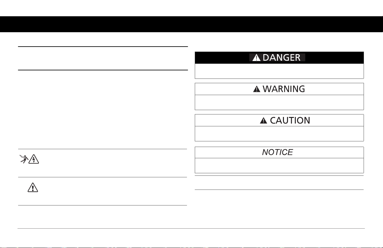
DANGER indicates an imminently hazardous situation, which, if not
avoided, will result in death or serious injury.
WARNING indicates a potentially hazardous situation, which, if not
avoided, can result in death or serious injury.
CAUTION indicates a potentially hazardous situation, which, if not
avoided, can result in moderate or minor injury.
The addition of either symbol to a “Danger” or “Warning” safety
label indicates that an electrical hazard exists which will result in
personal injury if the instructions are not followed.
This is the safety alert symbol. It is used to alert you to potential
personal injury hazards. Obey all safety messages that follow this
symbol to avoid possible injury or death.
NOTICE indicates a potentially hazardous situation, which, if not avoided,
can result in equipment damage.
IMPORTANT: These notes describe things which are important for you to
know, however, they are not as serious as a caution or warning.
97-0019-01-01 iii
Safety Information
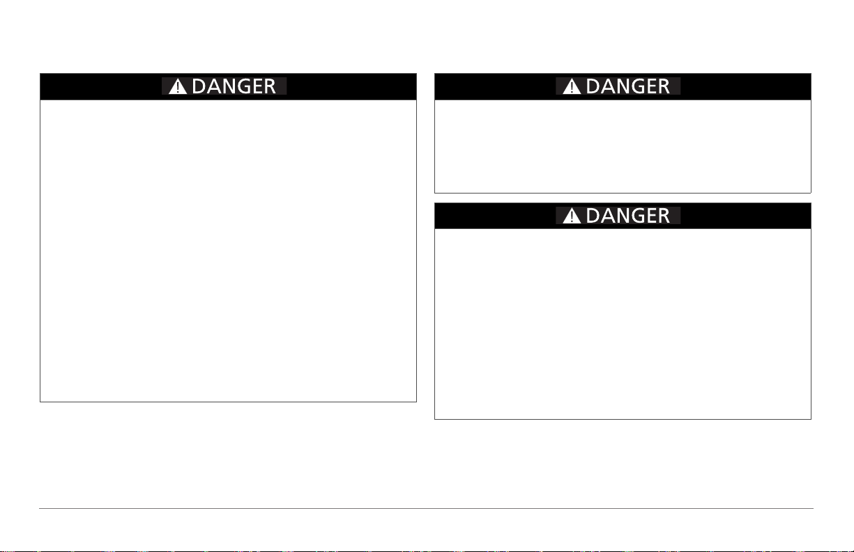
ELECTRICAL SHOCK HAZARD
• Do not expose the Freedom SW to rain, snow, spray, or bilge water.
This inverter/charger is designed for marine applications only when
additional drip protection is installed in certain orientations. See the
installation guide for information.
• Do not operate the inverter/charger if it has received a sharp blow,
been dropped, has cracks or openings in the enclosure including if
the AC terminal cover has been lost, damaged, or will not close, or
otherwise damaged in any other way.
• Do not disassemble the inverter/charger. Internal capacitors remain
charged after all power is disconnected.
• Disconnect both AC and DC power from the inverter/charger before
attempting any maintenance or cleaning or working on any circuits
connected to the inverter/charger. The INVERTER ENABLE button
on the front panel does not function like a power switch that
energizes or de-energizes the unit arbitrarily. When AC and DC power
sources are connected and present, the unit is always energized.
• Do not operate the inverter/charger with damaged or substandard
wiring. Make sure that all wiring is in good condition and is not
undersized.
Failure to follow these instructions will result in death or serious injury.
FIRE AND BURN HAZARD
• Do not cover or obstruct the air intake vent openings and/or install in
a zero-clearance compartment.
• Do not use transformerless battery chargers in conjunction with the
inverter/charger due to overheating.
Failure to follow these instructions will result in death or serious injury.
EXPLOSION HAZARD
• Charge only properly rated (such as 12 V) lead-acid (GEL, AGM,
Flooded, or lead-calcium) rechargeable batteries because other
battery types may explode.
• Do not work in the vicinity of lead-acid batteries. Batteries generate
explosive gases during normal operation. See note #1.
• Do not install and/or operate in compartments containing flammable
materials or in locations that require ignition-protected equipment.
See notes #2 and #3.
• When using Lithium-Ion batteries, ensure that the battery pack being
used includes a certified Battery Management System (BMS) with
safety controls.
Failure to follow these instructions will result in death or serious injury.
iv Freedom SW Owner’s Guide
NOTES:
1. Follow these instructions and those published by the battery
manufacturer and the manufacturer of any equipment you intend to use
in the vicinity of the battery. Review cautionary markings on these
products and on the engine.
2. This inverter/charger contains components which tend to produce arcs
or sparks.
3. Locations include any space containing gasoline-powered machinery,
fuel tanks, as well as joints, fittings, or other connections between
components of the fuel system.
Precautions When Working With Batteries
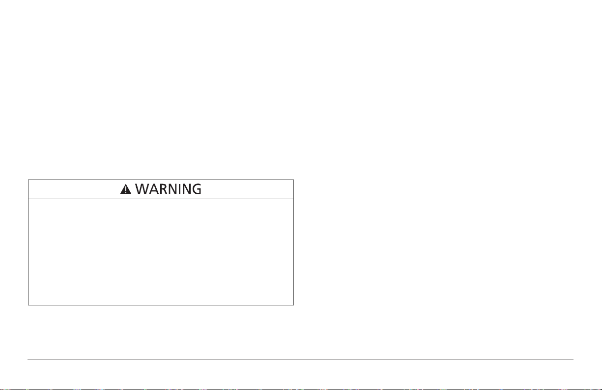
BURN FROM HIGH SHORT-CIRCUIT CURRENT, FIRE AND
EXPLOSION FROM VENTED GASES HAZARDS
• Always wear proper, non-absorbent gloves, complete eye protection,
and clothing protection. Avoid touching your eyes and wiping your
forehead while working near batteries. See note #4.
• Remove all personal metal items, like rings, bracelets, and watches
when working with batteries. See notes #5 and #6 below.
• Never smoke or allow a spark or flame near the engine or batteries.
• Never charge a frozen battery.
Failure to follow these instructions can result in death or serious injury.
2. Always have someone within range of your voice or close enough to
come to your aid when you work near a lead-acid battery.
3. Always have plenty of fresh water and soap nearby in case battery acid
contacts skin, clothing, or eyes.
4. If battery acid contacts skin or clothing, wash immediately with soap
and water. If acid enters your eye, immediately flood it with running
cold water for at least twenty minutes and get medical attention
immediately.
5. Use extra caution to reduce the risk or dropping a metal tool on the
battery. It could spark or short circuit the battery or other electrical
parts and could cause an explosion.
6. Batteries can produce a short circuit current high enough to weld a ring
or metal bracelet or the like to the battery terminal, causing a severe
burn.
7. When removing a battery, always remove the negative terminal from
the battery first for systems with grounded negative. If it is grounded
positive, remove the positive terminal first. Make sure all loads
connected to the battery and all accessories are off so you don’t cause
an arc.
NOTES:
1. Mount and place the Freedom SW Inverter/Charger unit away from
batteries in a well ventilated compartment.
97-0019-01-01 v
Precautions When Preparing to Charge
Precautions When Placing the Inverter/Charger
EXPOSURE TO CHEMICALS AND GASES HAZARD
• Make sure the area around the battery is well ventilated.
• Make sure the voltage of the batteries matches the output voltage of
the inverter/charger.
• Be careful to keep corrosion from coming into contact with your eyes
and skin when cleaning battery terminals.
Failure to follow these instructions can result in death or serious injury.
NOTES:
• Study and follow all of the battery manufacturer's specific precautions,
such as removing or not removing cell caps while charging, whether
equalization is acceptable for your battery, and recommended rates of
charge.
• For flooded non-sealed batteries, add distilled water in each cell until
battery acid reaches the level specified by the battery manufacturer.
This helps to purge excessive gas from cells. Do not overfill. For a
battery without removable cell caps, carefully follow manufacturer's
instructions.
RISK OF DAMAGE TO THE INVERTER/CHARGER
• Never allow battery acid to drip on the inverter/charger when reading
gravity, or filling battery.
• Never place the Freedom SW Inverter/Charger unit directly above
batteries; gases from a battery will corrode and damage the inverter/
charger.
• Do not place a battery on top of the inverter/charger.
Failure to follow these instructions can damage the unit and/or damage
other equipment.
vi Freedom SW Owner’s Guide
Regulatory
The Freedom SW Inverter/Charger is certified to appropriate US and
Canadian standards. For more information see “Regulatory Approvals” on
the Specifications section in the Owner’s Guide.
The Freedom SW Inverter/Charger is intended to be used for mobile or
commercial applications. This inverter/charger is designed for marine
applications only when additional drip protection is installed in certain
orientations.
It is not intended for other applications as it may not comply with the
additional safety code requirements needed for those other applications. See
“Limitations On Use” below.
LIMITATIONS ON USE
Do not use in connection with life support systems or other medical
equipment or devices.
Failure to follow these instructions can result in death or serious injury.
FCC Information to the User
This equipment has been tested and found to comply with the limits for a
Class B digital device, pursuant to part 15 of the FCC Rules. These limits
are designed to provide reasonable protection against harmful interference
in a residential installation. This equipment generates, uses, and can radiate
radio frequency energy and, if not installed and used in accordance with the
instructions, may cause harmful interference to radio communications.
However, there is no guarantee that interference will not occur in a
particular installation. If this equipment does cause harmful interference to
radio or television reception, which can be determined by turning the
equipment off and on, the user is encouraged to try to correct the
interference by one or more of the following measures:
• Reorient or relocate the receiving antenna.
• Increase the separation between the equipment and receiver.
• Connect the equipment into an outlet on a circuit different from that to
which the receiver is connected.
• Consult the dealer or an experienced radio/TV technician for help.
Unauthorized changes or modifications to the equipment could void the
user’s authority to operate the equipment.
97-0019-01-01 vii

End of Life Disposal
The Freedom SW is designed with environmental awareness and
sustainability in mind. At the end of its useful life, the Freedom SW can be
decommissioned and disassembled. Components which can be recycled
must be recycled and those that cannot be recycled must be disposed of
according to local, regional, or national environmental regulations.
Many of the electrical components used in the Freedom SW are made of
recyclable material like steel, copper, aluminum, and other alloys. These
materials can be auctioned off to traditional scrap metal recycling
companies who resell reusable scraps.
Electronic equipment such as the circuit boards, connectors, and fuses can
be broken down and recycled by specialized recycling companies whose
goal is to avoid having these components end up in the landfill.
For more information on disposal, contact Xantrex.
viii Freedom SW Owner’s Guide

Contents
Important Safety Instructions
Introduction . . . . . . . . . . . . . . . . . . . . . . . . . . . . . . . . . . . . . . . . . . . . . . . . . . . . . . . . . . . . . . . . . . . . . . . . . . . . . . . . . . . . . . . . . . . . . . . . . . . . 1
Materials List . . . . . . . . . . . . . . . . . . . . . . . . . . . . . . . . . . . . . . . . . . . . . . . . . . . . . . . . . . . . . . . . . . . . . . . . . . . . . . . . . . . . . . . . . . .2
Key Features . . . . . . . . . . . . . . . . . . . . . . . . . . . . . . . . . . . . . . . . . . . . . . . . . . . . . . . . . . . . . . . . . . . . . . . . . . . . . . . . . . . . . . . . . . .3
Key Features Explained . . . . . . . . . . . . . . . . . . . . . . . . . . . . . . . . . . . . . . . . . . . . . . . . . . . . . . . . . . . . . . . . . . . . . . . . . . . . . . .4
Stacking . . . . . . . . . . . . . . . . . . . . . . . . . . . . . . . . . . . . . . . . . . . . . . . . . . . . . . . . . . . . . . . . . . . . . . . . . . . . . . . . . . . . . . . . . . .5
Stack Charging . . . . . . . . . . . . . . . . . . . . . . . . . . . . . . . . . . . . . . . . . . . . . . . . . . . . . . . . . . . . . . . . . . . . . . . . . . . . . . . . . . . . . .5
Generator Assist . . . . . . . . . . . . . . . . . . . . . . . . . . . . . . . . . . . . . . . . . . . . . . . . . . . . . . . . . . . . . . . . . . . . . . . . . . . . . . . . . . . . .6
Basic Protection Features . . . . . . . . . . . . . . . . . . . . . . . . . . . . . . . . . . . . . . . . . . . . . . . . . . . . . . . . . . . . . . . . . . . . . . . . . . . . . . . . . . 6
System Components . . . . . . . . . . . . . . . . . . . . . . . . . . . . . . . . . . . . . . . . . . . . . . . . . . . . . . . . . . . . . . . . . . . . . . . . . . . . . . . . . . . . . . . . . . . . .7
Xanbus System . . . . . . . . . . . . . . . . . . . . . . . . . . . . . . . . . . . . . . . . . . . . . . . . . . . . . . . . . . . . . . . . . . . . . . . . . . . . . . . . . . . . . . . . . .7
Xanbus-enabled Products and Accessories . . . . . . . . . . . . . . . . . . . . . . . . . . . . . . . . . . . . . . . . . . . . . . . . . . . . . . . . . . . . . . . . . . . . 9
Freedom SW Inverter/Charger Mechanical Features . . . . . . . . . . . . . . . . . . . . . . . . . . . . . . . . . . . . . . . . . . . . . . . . . . . . . . . . . . . . . . . . . . .10
Freedom SW Front and Side Panels . . . . . . . . . . . . . . . . . . . . . . . . . . . . . . . . . . . . . . . . . . . . . . . . . . . . . . . . . . . . . . . . . . . . . . . .11
Freedom SW AC and DC Side Panels . . . . . . . . . . . . . . . . . . . . . . . . . . . . . . . . . . . . . . . . . . . . . . . . . . . . . . . . . . . . . . . . . . . . . . .14
Freedom SW Supplied Accessories . . . . . . . . . . . . . . . . . . . . . . . . . . . . . . . . . . . . . . . . . . . . . . . . . . . . . . . . . . . . . . . . . . . . . . . . .15
Freedom Inverter/Charger Operation . . . . . . . . . . . . . . . . . . . . . . . . . . . . . . . . . . . . . . . . . . . . . . . . . . . . . . . . . . . . . . . . . . . . . . . . . . . . . . .17
Start Up Behavior . . . . . . . . . . . . . . . . . . . . . . . . . . . . . . . . . . . . . . . . . . . . . . . . . . . . . . . . . . . . . . . . . . . . . . . . . . . . . . . . . . . . . .17
Inverter Operation Using the Front Panel . . . . . . . . . . . . . . . . . . . . . . . . . . . . . . . . . . . . . . . . . . . . . . . . . . . . . . . . . . . . . . . . . . . .18
Operating Limits for Inverter Operation . . . . . . . . . . . . . . . . . . . . . . . . . . . . . . . . . . . . . . . . . . . . . . . . . . . . . . . . . . . . . . . . . .20
Operating Limits for Charger Operation . . . . . . . . . . . . . . . . . . . . . . . . . . . . . . . . . . . . . . . . . . . . . . . . . . . . . . . . . . . . . . . . .21
. . . . . . . . . . . . . . . . . . . . . . . . . . . . . . . . . . . . . . . . . . . . . . . . . . . . . . . . . . . . . . . . . . . . . . . . . . . . . . . . . . . . iii

Operating the Freedom SW with the SCP. . . . . . . . . . . . . . . . . . . . . . . . . . . . . . . . . . . . . . . . . . . . . . . . . . . . . . . . . . . . . . . . . . . . . . . . . . . . 23
Using the Xanbus SCP . . . . . . . . . . . . . . . . . . . . . . . . . . . . . . . . . . . . . . . . . . . . . . . . . . . . . . . . . . . . . . . . . . . . . . . . . . . . . . . . . . .24
System Control Panel . . . . . . . . . . . . . . . . . . . . . . . . . . . . . . . . . . . . . . . . . . . . . . . . . . . . . . . . . . . . . . . . . . . . . . . . . . . . . . . .24
SCP Navigation . . . . . . . . . . . . . . . . . . . . . . . . . . . . . . . . . . . . . . . . . . . . . . . . . . . . . . . . . . . . . . . . . . . . . . . . . . . . . . . . . . . . . . . . 27
Startup Screen . . . . . . . . . . . . . . . . . . . . . . . . . . . . . . . . . . . . . . . . . . . . . . . . . . . . . . . . . . . . . . . . . . . . . . . . . . . . . . . . . . . . . .27
Viewing the SCP Home Screens . . . . . . . . . . . . . . . . . . . . . . . . . . . . . . . . . . . . . . . . . . . . . . . . . . . . . . . . . . . . . . . . . . . . . . .27
Soft Key Navigation . . . . . . . . . . . . . . . . . . . . . . . . . . . . . . . . . . . . . . . . . . . . . . . . . . . . . . . . . . . . . . . . . . . . . . . . . . . . . . . . . 29
Viewing the Firmware Revision Number . . . . . . . . . . . . . . . . . . . . . . . . . . . . . . . . . . . . . . . . . . . . . . . . . . . . . . . . . . . . . . . . . . . .31
Setting the Time and Date . . . . . . . . . . . . . . . . . . . . . . . . . . . . . . . . . . . . . . . . . . . . . . . . . . . . . . . . . . . . . . . . . . . . . . . . . . . . . . . .32
Using the STBY/ON Fault Clear Button . . . . . . . . . . . . . . . . . . . . . . . . . . . . . . . . . . . . . . . . . . . . . . . . . . . . . . . . . . . . . . . . . . . . .32
Reading the System Status Screen . . . . . . . . . . . . . . . . . . . . . . . . . . . . . . . . . . . . . . . . . . . . . . . . . . . . . . . . . . . . . . . . . . . . . . . . . .33
Reading the Freedom SW Device Setup Screen . . . . . . . . . . . . . . . . . . . . . . . . . . . . . . . . . . . . . . . . . . . . . . . . . . . . . . . . . . . . . . .35
Configuring the Freedom SW using the SCP . . . . . . . . . . . . . . . . . . . . . . . . . . . . . . . . . . . . . . . . . . . . . . . . . . . . . . . . . . . . . . . . . . . . . . . . .39
System Menu Map . . . . . . . . . . . . . . . . . . . . . . . . . . . . . . . . . . . . . . . . . . . . . . . . . . . . . . . . . . . . . . . . . . . . . . . . . . . . . . . . . . . . . . 39
Viewing the System Status Screen . . . . . . . . . . . . . . . . . . . . . . . . . . . . . . . . . . . . . . . . . . . . . . . . . . . . . . . . . . . . . . . . . . . . . . 40
Viewing the Select Device Menu . . . . . . . . . . . . . . . . . . . . . . . . . . . . . . . . . . . . . . . . . . . . . . . . . . . . . . . . . . . . . . . . . . . . . . .40
Selecting the Freedom SW from the Select Device Menu . . . . . . . . . . . . . . . . . . . . . . . . . . . . . . . . . . . . . . . . . . . . . . . . . . . .41
Changing Configurable Settings From The Device Setup Menu Screen . . . . . . . . . . . . . . . . . . . . . . . . . . . . . . . . . . . . . . . . . . . .42
Using Search Mode . . . . . . . . . . . . . . . . . . . . . . . . . . . . . . . . . . . . . . . . . . . . . . . . . . . . . . . . . . . . . . . . . . . . . . . . . . . . . . . . . .45
Equalization Procedure . . . . . . . . . . . . . . . . . . . . . . . . . . . . . . . . . . . . . . . . . . . . . . . . . . . . . . . . . . . . . . . . . . . . . . . . . . . . . . .47
Changing Freedom SW Basic Settings . . . . . . . . . . . . . . . . . . . . . . . . . . . . . . . . . . . . . . . . . . . . . . . . . . . . . . . . . . . . . . . . . . . . . .48
Changing Freedom SW Advanced Settings . . . . . . . . . . . . . . . . . . . . . . . . . . . . . . . . . . . . . . . . . . . . . . . . . . . . . . . . . . . . . . . . . . . 52
Inverter Settings Menu . . . . . . . . . . . . . . . . . . . . . . . . . . . . . . . . . . . . . . . . . . . . . . . . . . . . . . . . . . . . . . . . . . . . . . . . . . . . . . . . . . . 56
Using the Low Battery Cut Out and LBCO Delay Settings . . . . . . . . . . . . . . . . . . . . . . . . . . . . . . . . . . . . . . . . . . . . . . . . . . .57
Charger Settings Menu . . . . . . . . . . . . . . . . . . . . . . . . . . . . . . . . . . . . . . . . . . . . . . . . . . . . . . . . . . . . . . . . . . . . . . . . . . . . . . . . . .59
Battery Charger Functions . . . . . . . . . . . . . . . . . . . . . . . . . . . . . . . . . . . . . . . . . . . . . . . . . . . . . . . . . . . . . . . . . . . . . . . . . . . .61
Custom Battery Settings Menu . . . . . . . . . . . . . . . . . . . . . . . . . . . . . . . . . . . . . . . . . . . . . . . . . . . . . . . . . . . . . . . . . . . . . . . . .62

ACIn Settings . . . . . . . . . . . . . . . . . . . . . . . . . . . . . . . . . . . . . . . . . . . . . . . . . . . . . . . . . . . . . . . . . . . . . . . . . . . . . . . . . . . . . . . . . .64
Gen Support . . . . . . . . . . . . . . . . . . . . . . . . . . . . . . . . . . . . . . . . . . . . . . . . . . . . . . . . . . . . . . . . . . . . . . . . . . . . . . . . . . . . . . . . . . .66
Stacking Configuration Menu . . . . . . . . . . . . . . . . . . . . . . . . . . . . . . . . . . . . . . . . . . . . . . . . . . . . . . . . . . . . . . . . . . . . . . . . . . . . .68
Setting the Device Name . . . . . . . . . . . . . . . . . . . . . . . . . . . . . . . . . . . . . . . . . . . . . . . . . . . . . . . . . . . . . . . . . . . . . . . . . . . . .70
Setting the Device Number . . . . . . . . . . . . . . . . . . . . . . . . . . . . . . . . . . . . . . . . . . . . . . . . . . . . . . . . . . . . . . . . . . . . . . . . . . . .71
Cascading . . . . . . . . . . . . . . . . . . . . . . . . . . . . . . . . . . . . . . . . . . . . . . . . . . . . . . . . . . . . . . . . . . . . . . . . . . . . . . . . . . . . . . . . . . . . .72
Resetting the Freedom SW to Default Settings . . . . . . . . . . . . . . . . . . . . . . . . . . . . . . . . . . . . . . . . . . . . . . . . . . . . . . . . . . . . . . . .73
Using the Advanced Features . . . . . . . . . . . . . . . . . . . . . . . . . . . . . . . . . . . . . . . . . . . . . . . . . . . . . . . . . . . . . . . . . . . . . . . . . . . . .74
Battery Charging Reference . . . . . . . . . . . . . . . . . . . . . . . . . . . . . . . . . . . . . . . . . . . . . . . . . . . . . . . . . . . . . . . . . . . . . . . . . . . . . . . . . . . . . .76
Battery Types . . . . . . . . . . . . . . . . . . . . . . . . . . . . . . . . . . . . . . . . . . . . . . . . . . . . . . . . . . . . . . . . . . . . . . . . . . . . . . . . . . . . . . . . . .76
Charge Algorithm Stages . . . . . . . . . . . . . . . . . . . . . . . . . . . . . . . . . . . . . . . . . . . . . . . . . . . . . . . . . . . . . . . . . . . . . . . . . . . . . . . . .77
Three-Stage charging . . . . . . . . . . . . . . . . . . . . . . . . . . . . . . . . . . . . . . . . . . . . . . . . . . . . . . . . . . . . . . . . . . . . . . . . . . . . . . . .77
Two-Stage Charging Process . . . . . . . . . . . . . . . . . . . . . . . . . . . . . . . . . . . . . . . . . . . . . . . . . . . . . . . . . . . . . . . . . . . . . . . . . .81
Equalize Charging . . . . . . . . . . . . . . . . . . . . . . . . . . . . . . . . . . . . . . . . . . . . . . . . . . . . . . . . . . . . . . . . . . . . . . . . . . . . . . . . . . . . . . 83
Troubleshooting. . . . . . . . . . . . . . . . . . . . . . . . . . . . . . . . . . . . . . . . . . . . . . . . . . . . . . . . . . . . . . . . . . . . . . . . . . . . . . . . . . . . . . . . . . . . . . . .85
General Troubleshooting Guidelines . . . . . . . . . . . . . . . . . . . . . . . . . . . . . . . . . . . . . . . . . . . . . . . . . . . . . . . . . . . . . . . . . . . . . . . . 85
Inverter Applications . . . . . . . . . . . . . . . . . . . . . . . . . . . . . . . . . . . . . . . . . . . . . . . . . . . . . . . . . . . . . . . . . . . . . . . . . . . . . . . . . . . .86
Resistive Loads . . . . . . . . . . . . . . . . . . . . . . . . . . . . . . . . . . . . . . . . . . . . . . . . . . . . . . . . . . . . . . . . . . . . . . . . . . . . . . . . . . . . .86
Motor Loads . . . . . . . . . . . . . . . . . . . . . . . . . . . . . . . . . . . . . . . . . . . . . . . . . . . . . . . . . . . . . . . . . . . . . . . . . . . . . . . . . . . . . . .86
Problem Loads . . . . . . . . . . . . . . . . . . . . . . . . . . . . . . . . . . . . . . . . . . . . . . . . . . . . . . . . . . . . . . . . . . . . . . . . . . . . . . . . . . . . .86
Troubleshooting the Freedom SW via the SCP . . . . . . . . . . . . . . . . . . . . . . . . . . . . . . . . . . . . . . . . . . . . . . . . . . . . . . . . . . . . . . . . 88
Detected Fault Types . . . . . . . . . . . . . . . . . . . . . . . . . . . . . . . . . . . . . . . . . . . . . . . . . . . . . . . . . . . . . . . . . . . . . . . . . . . . . . . .88
Detected Warning Types . . . . . . . . . . . . . . . . . . . . . . . . . . . . . . . . . . . . . . . . . . . . . . . . . . . . . . . . . . . . . . . . . . . . . . . . . . . . .90
Specifications . . . . . . . . . . . . . . . . . . . . . . . . . . . . . . . . . . . . . . . . . . . . . . . . . . . . . . . . . . . . . . . . . . . . . . . . . . . . . . . . . . . . . . . . . . . . . . . .103


Introduction
Congratulations on your purchase of the Freedom SW
Inverter/Charger (Freedom SW). The Freedom SW has been
designed to give you premium power, ease of use, and
outstanding reliability.
Please read this chapter to familiarize yourself with the main
performance and protection features of the Freedom SW.
97-0019-01-01 1
Introduction
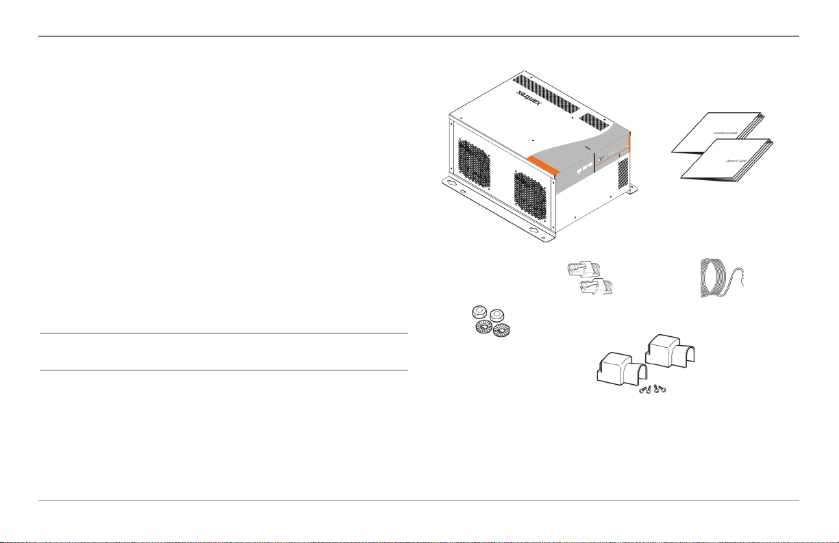
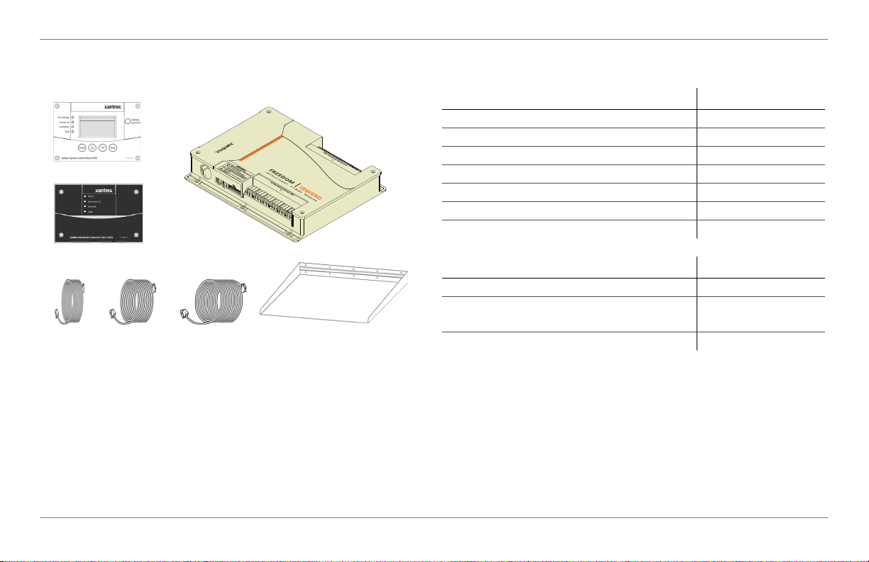
Materials List
The Freedom SW ships with the following items:
• One Freedom SW unit
• Owner’s and Installation Guides
• Battery Temperature Sensor (BTS)
• DC terminal covers (one red, one black) with
two sets of #6-32 screws
• Two Xanbus network terminators
• Two sets of 5/16”-18 nuts and washers for the DC
terminals
NOTE: If any of the items are missing, contact customer
service or any authorized Xantrex dealer for replacement. See
“About This Guide” on page ii.
3012
FAULT
AC IN
WARNING
INVERTER
ENABLED
CHARGING
INVERTER
3012
GEN
ENABLE
SUPPORT
RESET
CLEAR FAULT
SW
FREEDOM SW
FREEDOM
Freedom SW 3012 shown
Xanbus network
terminators
Installation and
Owner’s Guides
BTS
IMPORTANT:
to return the Freedom SW for servicing.
Keep the carton and packing material in case you need
nuts and washers
DC terminal covers
with screws
Figure 1 Materials List
2 Freedom SW Owner’s Guide

Key Features
The Freedom SW Inverter/Charger is a true sine wave
inverter/charger that can be used for mobile, marine and
commercial applications. The Freedom SW Inverter/Chargers
are designed to operate with a wide variety of generators and
are capable of operating in parallel with a generator for short
durations to assist with starting large loads. The Freedom SW
is a convenient combination of an inverter, multistage battery
charger, and transfer switch in one electronic device.
• As an inverter, the Freedom SW provides true sine wave power
for your microwave, entertainment system, computer, and other
loads. This power is identical to the AC source provided from the
utility grid (power company).
• Some of the benefits of true sine wave power include
consistent cooking in your microwave, handling of
sensitive loads such as your TV set, dimmer switches, and
appliances with speed controls.
• Highly versatile platform capable of series stacking for
120/240V line configurations and parallel stacking to
increase power levels.
• High efficiency true sine wave output to power sensitive
electrical and electronic equipment.
• Surge capacity to start difficult loads like refrigerators or
• Power factor-corrected (PFC) input minimizes AC input current
• As a charger, it has high output, multistage charging
• Capable of operating from 50 Hz and 60 Hz power source
• Temperature-controlled, variable-speed internal cooling
• Designed with serviceability in mind via Authorized
• The Freedom SW Inverter/Charger is also Xanbus-enabled
Introduction
A/C compressors.
required for charging, increasing AC pass-through capacity.
capability minimizing charging time.
by extending AC qualification frequency range. See
“ACIn Settings” on page 64.
IMPORTANT: Dual Line models require only the Line 1
Input to be energized in order to qualify AC. Line 2 Input
does not have to be powered in a single phase system.
fans. The fans turn on when the internal temperature
reaches 45 °C (113 °F) and reaches maximum speed at 70
°C (158 °F). The fan turns off when the internal
temperature falls to 40 °C (104 °F).
Service Centers (ASC).
which allows network compatibility and communication
with other Xanbus-enabled devices. See more information
under “System Components” on page 7.
97-0019-01-01 3

Introduction
Key Features Explained
Built-in Charge Formulas For the unit to perform at the
highest level, the batteries must be charged correctly. The
Freedom SW has optimized algorithms for flooded, gel, and
AGM batteries.
Battery Temperature Sensor Since battery temperature is
a key factor in correct charging, the charging formula must be
adjusted (automatically and in real time) according to the
actual battery temperature to ensure that batteries are fully
charged, but not overcharged. For this reason, a battery
temperature sensor is included with your Freedom SW and
has temperature compensated the charge formula.
Manual Equalization Over a period of time, the cells in a
flooded battery can develop uneven chemical states. This can
result in a weak (undercharged) cell which, in turn, can reduce
the overall capacity of the battery. To improve the life and
performance of a non-sealed, flooded battery, the Freedom
SW’s multistage charging cycle includes a manual equalize
mode that can be used, if recommended by the battery
manufacturer.
Dead Battery Charging Another feature that the Freedom
SW includes is dead battery charging. The Freedom SW—
unlike many chargers—has the ability to recharge batteries
even if the battery voltage is very low (5 volts for Freedom
SW 2012 / 3012 units and 12 volts for Freedom SW 2024 /
3024 units).
Load Management The Freedom SW has a built-in
transfer relay that connects your inverter output or AC input
from the utility grid or generator to your loads. Because the
usual AC power sources such as campground outlets or small
generators often have limited current availability, having the
capability to manage your AC loads is extremely valuable.
The Freedom SW provides a number of features to facilitate
this:
• The charger is power factor corrected to use AC current
as efficiently as possible. Minimizing the AC current used
by the charger means more current is available for your
AC loads.
• Freedom SW has a power share feature which prioritizes
your AC loads by reducing the charge current in an
attempt to limit the total input current to less than the
breaker setting.
Occasionally, AC input sources have low voltage. To avoid
loading these weak sources any further, the charger
automatically reduces its AC current draw as the AC voltage
approaches the minimum acceptable level.
4 Freedom SW Owner’s Guide

Stacking
Introduction
Stack Charging
Supports stacking of two inverter/chargers to increase
capacity. This also requires the installer to select a Master and
Slave in order for the inverters to stack. Two configurations
of stacking are supported: Parallel stacking and Series
stacking.
Parallel Stacking Parallel stacking allows two inverter/
chargers to operate in parallel thereby doubling the capacity
in inverter mode. The two inverters communicate over the
network and intelligently share the load and to balance the
load between the two units. The Master Freedom SW
broadcasts pulses on the Xanbus network to synchronize
operation between the other paralleled unit. When AC loads
are present, both units produce power, effectively sharing the
load. When Search mode is enabled, only the Master unit
produces the AC output.
Series Stacking Two units can be configured to generate
120/240 Split-phase power for load configurations that
require both 120 and 240 volts. In this configuration, the AC
source must be split-phase as well.
Two Freedom SWs synchronize charging stages to ensure
efficient charging of the battery bank. When a single unit
transitions from bulk to absorption so do all other units. In
absorption, all units must complete the absorption stage
before transitioning to the next stage. Note that units do not
load share when charging except during the bulk stage. The
Freedom SWs stop sharing charge current just before
completing the bulk stage. The units do not share charge
current during the absorption and float stages.
Each unit charges batteries based on the Max Charge Rate
setting and active internal (temperature-based) deratings.
If equalization is enabled on one or more devices capable of
equalization charging, only those devices perform an equalize
cycle after absorption. Other devices transition to float (if
three-stage charging is selected) or transition to AC passthrough (if two-stage charging is selected).
97-0019-01-01 5

Introduction
Generator Assist
The Freedom SW Series of inverter/chargers can operate in
tandem with a generator (or shore power) to temporarily
assist power loads with large start-up demands such as air
conditioners, water pumps etc. A Xanbus AGS is not required
for this feature to work when shore power is present to assist
the Freedom SW but the AGS is needed if a generator were to
be used in assisting the Freedom SW.
When the Gen Support mode is enabled and the generator’s
or shore power’s current capacity defined (in amps), the
inverter will come on-line and assist the generator or shore
power with starting and operating the load (drawing power
from the battery). The battery bank must be well charged in
order for the inverter to engage this mode. For more details,
see “Gen Support” on page 66.
Basic Protection Features
The Freedom SW has the following protection features:
• Over temperature shutdown for critical components such
as the transformer and the power board
• Battery temperature sensor (BTS) failure/battery
temperature out-of-range fault protection
• DC output over voltage protection during charge mode
• AC transfer relay failure detection
• AC output overload and short circuit protection during
invert mode
• AC backfeed
• Short circuit protection for the BTS and communication
connector ports including protection from incorrectly
inserting the remote panel communication cable plug into
the BTS port and vice versa
The Battery Temperature Sensor (BTS) provides these
protection features:
• Battery over temperature charging protection preventing
battery charging at 60 °C (140 °F) or higher
• Charging voltage compensation based on the temperature
of the battery where the BTS is connected
1
protection
1.An AC backfeed error occurs when the AC output of the inverter/charger is connected or routed back to the inverter/charger’s AC input terminal or if the internal
transfer relay fails.
6 Freedom SW Owner’s Guide
System Components
The Freedom SW uses Xanbus, a network communications
protocol developed to communicate the Freedom SW’s
settings and activity to other Xanbus-enabled devices.
You can configure and monitor the Freedom SW and every
Xanbus-enabled device in the system using an optional
Xanbus System Control Panel (SCP).
Another component is the optional Xanbus Automatic
Generator Start (AGS) which allows operation with a wide
range of generators, supported through a dedicated generator
input. Simply, the AGS automatically starts and stops your
generator.
The Freedom Sequence Intelligent Power Manager is a fully
integrated power management system that provides automatic
power and load management for use in recreational vehicles
(RV) while receiving power from a generator or shore power.
This device works in the background to prevent monitored
AC loads from exceeding shore and generator breaker
capacity.
See “Xanbus-enabled Products and Accessories” on page 9
for part numbers.
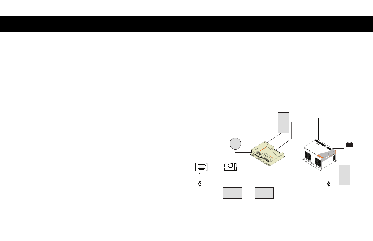
Xanbus System
The Xanbus system includes the Freedom SW and other
Xanbus-enabled devices. The Freedom SW is the device in a
Xanbus system that typically provides network power—500
mA at 12 volts DC. All of the Xanbus-enabled devices, such
as the Freedom SW, the SCP, and the AGS are able to
communicate their settings and activity to each other. See
Figure 2.
AC Panel
Shore
Power
System Control Panel
Xanbus System Control Panel
network terminator network terminator
Automatic Generator Start
Xanbus Automatic Generator Start
Generator
Figure 2 Typical Xanbus System Diagram
Freedom Sequence
AC Loads
Freedom SW Inverter/Charger
FREEDOMSW
BATTERY
3012
Fault
C/
ge
r
r A
e
t
ha
r
C
e
v
n
I
n
O
r
e
t
r
e
v
n
I
Enable
3012
set
e
R
SW
FREEDOM
Inverter
Load Panel
97-0019-01-01 7

System Components
The Xanbus-enabled designation (see below) means that this
product works on a Xanbus network. Xanbus-enabled
products are:
• Simple to operate and routine tasks are automated.
• Controlled by software that eliminates analog signalling
errors.
• Less susceptible to interference and line loss.
• Upgradable through new software releases.
For detailed instructions and a complete list of Xanbusenabled devices, visit www.xantrex.com.
8 Freedom SW Owner’s Guide
Xanbus-enabled Products and Accessories
System Components
SCP
AGS
Freedom
Sequence
Product/Accessory (Shown above) Product Number/s
Freedom Sequence Intelligent Power Manager 809-0912 / 809-0913
Xanbus System Control Panel (SCP) 809-0921
Xanbus Automatic Generator Start (AGS) 809-0915
3-ft network cable (0.9 m) 809-0935
25-ft network cable (7.6 m) 809-0940
75-ft network cable (22.9 m) 809-0942
Inverter drip shield 808-9004
Product/Accessory (Not Shown) Product Number/s
Freedom SW On/Off Switch 808-9002
GFCI receptacles
808-9003
(available on 12 VDC models only)
25-ft cable 75-ft cable3-ft cable
Inverter drip shield
Stacking cable 808-9005
97-0019-01-01 9
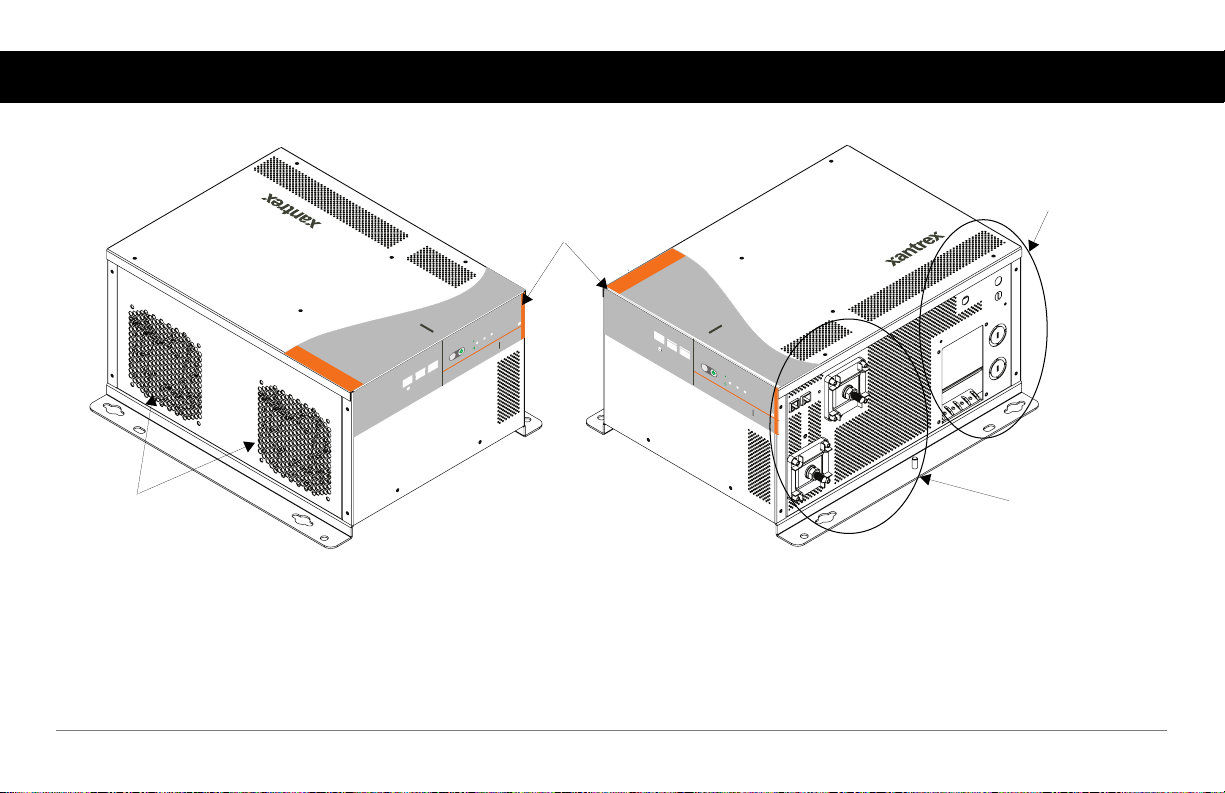
Freedom SW Inverter/Charger Mechanical Features
Front Panel
Controls and
Status LEDs
Compartment
AC
Side
FREEDOM SW
3012
Cooling Fans
FREEDOM SW
FAULT
AC IN
WARNING
INVERTER
ENABLED
CHARGING
INVERTER
3012
GEN
ENABLE
SUPPORT
RESET
CLEAR FAULT
SW
FREEDOM
3012
CLEAR FAULT
RESET
INVERTER
ENABLE
INVERTER
ENABLED AC IN
GEN
SUPPORT
FAULT
CHARGING
WARNING
FREEDOM
SW
3012
DC Terminal Side and
Ground Terminal Stud
Figure 3 Freedom SW Front and Side Panels (Freedom SW 3012 shown)
10 Freedom SW Owner’s Guide
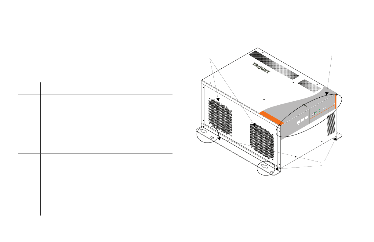
Freedom SW Front and Side Panels
Before you begin to operate the Freedom SW, review the
front panel features shown in Figure 4 and described in the
next table. A detailed view of the LEDs and buttons on the
front panel is shown in Figure 5 and described in the table
next to it.
Item Description
Freedom SW Inverter/Charger Mechanical Features
3
1
1 Front Panel contains the Xanbus interface ports for
connecting Xanbus-enabled devices, the
INVERTER ENABLE and CLEAR FAULT
RESET buttons, as well as various status LEDs.
FREEDOM SW
3012
FAULT
AC IN
WARNING
INVERTER
ENABLED
CHARGING
INVERTER
3012
GEN
ENABLE
SUPPORT
RESET
CLEAR FAULT
SW
FREEDOM
See Figure 5.
2 Mounting holes are used for mounting the unit. A
total of eight holes are provided on the unit.
3 Two variable-speed cooling fans are used to cool
the unit. Fan speed control is based on internal
2
temperature of critical components. The two
cooling fans draw airflow into the inverter around
the transformer and power compartments of the unit
Figure 4 Isometric View of the Front Panel and Fans
then exhaust through the other vents. Ensure at least
3 inches (76 mm) of clearance for proper
ventilation.
97-0019-01-01 11

Freedom SW Inverter/Charger Mechanical Features
FREEDOM SW
3012
CLEAR FAULT
RESET
INVERTER
ENABLE
INVERTER
ENABLED
AC IN
GEN
SUPPORT
FAULT
CHARGINGWARNING
FREEDOM
SW
3012
XANBUS INTERFACE STACKING
79 8
CLEAR FAULT
INVERTER
RESET
ENABLE
FREEDOM SW INVERTER/CHARGER
INVERTER
ENABLED
SUPPORT
GEN
314256
AC IN FAULT
CHARGING WARNING
Item Description
1 DC terminals.
2 AC wiring compartment access panel with
compartment cover on.
3 FAULT LED turns on solid if a fault condition occurs
and flashes intermittently when a WARNING condition
is active.
4 When AC is present and qualified, the AC IN LED will
turn on solid indicating also that AC is passing through.
CHARGING LED flashes intermittently when the
Freedom SW is in charge mode and is producing DC
output to charge your batteries.
5 INVERTER ENABLED indicates the invert mode is
enabled. This is different from the inverter being “on”.
When enabled the inverter can be on or off. When
disabled, the inverter is always off. If AC is present and
invert mode is enabled, this LED remains illuminated
even though AC power is being passed through.
GEN SUPPORT LED flashes intermittently when the
inverter is in generator support mode and is assisting the
generator.
6 INVERTER ENABLE button is used to enable or
disable the inverter.
Figure 5 Isometric View of the Front Panel and AC/DC Side Panel
12 Freedom SW Owner’s Guide

Item Description
7 CLEAR FAULT RESET button is used to clear any
active faults if pressed momentarily. If held down for
more than three seconds, the unit will reset (reboot)
itself.
8 STACKING port is used to connect two inverter/
chargers together for stacked operation. This is required
only for stacking in series.
9 XANBUS INTERFACE ports are used to connect
Xanbus-enabled devices including the optional SCP and
AGS.
Freedom SW Inverter/Charger Mechanical Features
97-0019-01-01 13
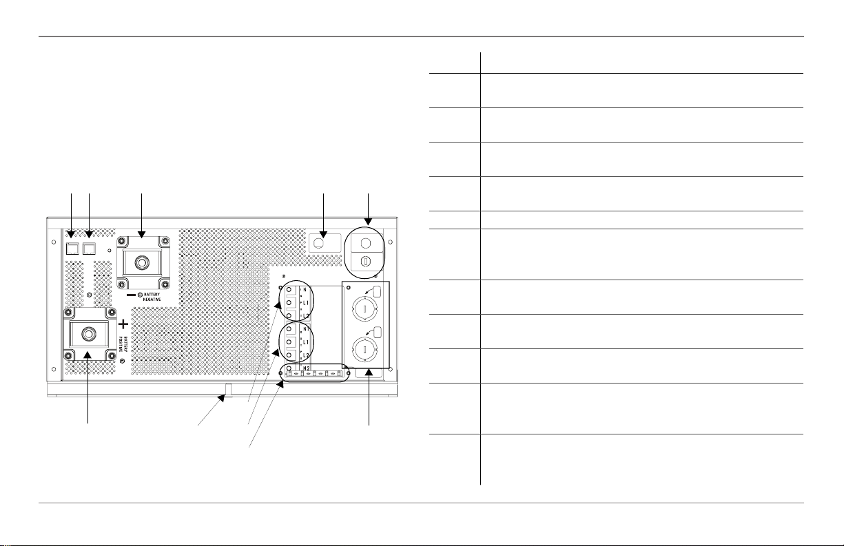
Freedom SW Inverter/Charger Mechanical Features
Freedom SW AC and DC Side Panels
The DC side of the Freedom SW has the equipment ground
lug, the positive (+) battery terminal, and the negative (-)
battery terminal plus the remote network com port and battery
temperature sensor com port.
1 23 5
INCORRECT BATTERY
POL
ARI
T
Y
W
I
L
L
CAU
SE
DA
M
AGE
T
O
UN
I
T.
WIRING BOX COVER MUST BE IN PLACE DURING
OPERATION TO REDUCE RISK OF INJURY TO PERSONS.
CAUTION:
BTS
REM
8
11
9
10
Figure 6 AC and DC Side Panel
6
AC OUTPUT
INVERTER
AC INPUT 1
CHARGER
AC GROUNDS
(BEHIND COVER)
30A
AC INPUT 2
PASS THRU
30A
AC
IN
AC
OUT
30A
74
Item Description
1 Remote (REM) jack provides connection for the
Freedom Sine Wave remote panel.
2 Battery temperature sensor (BTS) jack provides
connection for the battery temperature sensor (supplied).
3 Negative (–) DC terminal (black). Use a qualified
personnel for connecting cables.
4 Positive (+) DC terminal (red). Use a qualified
personnel for connecting cables.
5 AC Output circuit breaker reset button
6 AC Input circuit breakers reset buttons. See “Shore
(Shr) setting” on page 29 and “AC In Breaker” on
page 51.
7 AC knockouts provide access for AC cables (both input
and output wiring).
8 AC Input screw-type terminal block. Use a qualified
personnel for connecting wires.
9 AC Output screw-type terminal block. Use a qualified
personnel for connecting wires.
10 Ground terminals along the tab at the bottom of the
opening to the AC wiring compartment access panel.
Use a qualified personnel for connecting wires.
11 Chassis ground lug connects the chassis of the
Freedom SW to your system’s chassis grounding point.
Use a qualified personnel for connecting wires.
14 Freedom SW Owner’s Guide
Freedom SW Inverter/Charger Mechanical Features
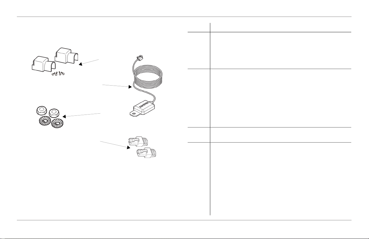
Freedom SW Supplied Accessories
1
2
3
4
Figure 7 Supplied Accessories
NOTE: If any of the supplied accessories are missing, contact
customer service or any authorized dealer for replacement.
Item Description
1 Two DC terminal covers are supplied to prevent
accidental
contact with the DC cable connectors after installation.
The red cover is for the positive cabling terminal, and
the black cover is for the negative cabling terminal.
2 BTS, the Battery Temperature Sensor consists of:
Connector plugs into the BTS jack on the Freedom SW.
Sensor cable is 25 feet (7.6 meters).
Sensor can be mounted on the side of the battery case or
on the negative battery terminal.
NOTE: The BTS continuously measures the
temperature of the battery and adjusts the charger output
for a more accurate, temperature-compensated charge.
3 Two sets of nuts and washers are used to secure DC
cable ends to the DC terminals.
4 Two Xanbus network terminators are used to properly
terminate each of the two ends of the daisy-chained
Xanbus network. For example, if the Xanbus SCP is
connected to the inverter/charger, one terminator will be
plugged to the SCP, one network cable will connect both
devices, and one terminator will be plugged to the
inverter/charger.
IMPORTANT: The Xanbus SCP may perform
erratically if the Xanbus network is not properly
terminated.
97-0019-01-01 15

 Loading...