

Xantrex 807-1055-02, 807-2055-01, 807-2055, 807-2055-02 Owner's Manual
TM
TM
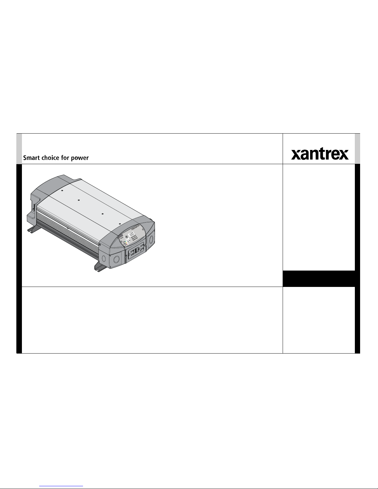
Freedom HFS Inverter/Chargers
Owner’s Guide
Product image shown may vary from actual product. See features for comparisons.
Model Product Numbers
807-1055
807-1055-02
807-2055
807-2055-01
807-2055-02


975-0727-01-01 i
Copyright © 2015 Schneider Electric. All Rights Reserved. All trademarks are
owned by Schneider Electric Industries SAS or its affiliated companies.
Exclusion for Documentation
UNLESS SPECIFICALLY AGREED TO IN WRITING, SELLER
(A) MAKES NO WARRANTY AS TO THE ACCURACY, SUFFICIENCY OR SUITABILITY OF ANY
TECHNICAL OR OTHER INFORMATION PROVIDED IN ITS MANUALS OR OTHER DOCUMENTATION;
(
B) ASSUMES NO RESPONSIBILITY OR LIABILITY FOR LOSSES, DAMAGES, COSTS OR EXPENSES,
WHETHER SPECIAL, DIRECT, INDIRECT, CONSEQUENTIAL OR INCIDENTAL, WHICH MIGHT ARISE
OUT OF THE USE OF SUCH INFORMATION. THE USE OF ANY SUCH INFORMATION WILL BE ENTIRELY
AT THE USER’S RISK; AND
(C) REMINDS YOU THAT IF THIS MANUAL IS IN ANY LANGUAGE OTHER THAN ENGLISH,
ALTHOUGH STEPS HAVE BEEN TAKEN TO MAINTAIN THE ACCURACY OF THE TRANSLATION, THE
ACCURACY CANNOT BE GUARANTEED. APPROVED CONTENT IS CONTAINED WITH THE ENGLISH
LANGUAGE VERSION WHICH IS POSTED AT WWW.XANTREX.COM.
Document Part Number
975-0727-01-01
Date and Revision
April 2015 Rev A
Product Numbers
Freedom HFS 1055 (1000-watt) Models:
807-1055 (Freedom HFS 1055 120VAC Standard Model)
807-1055-02 (Freedom HFS 1055 120VAC EMS Model)
Freedom HFS 2055 (2000-watt) Models:
807-2055 (Freedom HFS 2055 120VAC Standard Model)
807-2055-01 (Freedom HFS 2055 120VAC Truck Model)
807-2055-02 (Freedom HFS 2055 120VAC EMS Model)
Contact Information
Information About Your System
As soon as you open your product, record the following information and be sure to
keep your proof of purchase.
To view, download, or print the latest revision, visit the website shown under Contact
Information.
Telephone: +1 800 670 0707
+1 408 987 6030
Web: www.xantrex.com
Serial Number
_________________________________
Product Number
_________________________________
Purchased From
_________________________________
Purchase Date
_________________________________

ii Freedom HFS Owner’s Guide
About This Guide
Purpose
The purpose of this Owner’s Guide is to provide explanations and
procedures for operating, maintaining, and troubleshooting a Freedom HFS
Sine Wave Inverter/Charger for Recreational, Fleet Vehicle, or Marine
installations.
For complete information to help in installing a Freedom HFS Sine Wave
Inverter/Charger see the Freedom HFS Sine Wave Inverter/Charger
Installation Guide (Doc. Part Number: 975-0726-01-01).
Scope
The Guide provides safety and operating guidelines as well as information
on configuring the inverter/charger. It also provides information about
troubleshooting the unit. It does not provide details about particular brands
of batteries. You need to consult individual battery manufacturers for this
information.
Audience
The Guide is intended for users and operators of the Freedom HFS Sine
Wave Inverter/Charger.
Related Information
You can find more information about Xantrex products and services at
www.xantrex.com.
NOTE: The Installation Guide (Document Part Number: Freedom HFS
Sine Wave Inverter/Charger Installation Guide (Doc. Part Number: 9750726-01-01)) is intended for qualified personnel. Qualified personnel have
training, knowledge, and experience in:
• Installing electrical equipment (up to 1000 volts).
• Applying all applicable installation codes.
• Analyzing and reducing the hazards involved in performing electrical
work.
• Selecting and using Personal Protective Equipment (PPE).
975-0727-01-01 iii
Important Safety Instructions
IMPORTANT: READ AND SAVE THIS OWNER’S GUIDE
FOR FUTURE REFERENCE.
This guide contains important safety instructions for the Freedom HFS Sine
Wave Inverter/Charger that must be followed during operation and
troubleshooting. Read and keep this Owner’s Guide for future
reference.
Read these instructions carefully and look at
the equipment to become
familiar with the device before trying to install, operate, service or maintain
it. The following special messages may appear throughout this bulletin or
on the equipment to warn of potential hazards or to call attention to
information that clarifies or simplifies a procedure.
The addition of either symbol to a “Danger” or “Warning”
safety label indicates that an electrical hazard exists which
will result in personal injury if the instructions are not
followed.
This is the safety alert symbol. It is used to alert you to
potential personal injury hazards. Obey all safety
messages that follow this symbol to avoid possible injury
or death.
DANGER indicates an imminently hazardous situation, which, if not
avoided, will result in death or serious injury.
WARNING indicates a potentially hazardous situation, which, if not
avoided, can result in death or serious injury.
CAUTION indicates a potentially hazardous situation, which, if not
avoided, can result in moderate or minor injury.
NOTICE indicates a potentially
hazardous situation, which, if not
avoided, can result in equipment damage.
These notes describe things which
are important for you
to know, however, they are not as serious as a caution or warning.
IMPORTANT:

iv Freedom HFS Owner’s Guide
Safety Information
1. Before using the inverter/charger, read all instructions and
cautionary markings on the unit, the batteries, and all appropriate
sections of this manual.
2. Use of accessories not recommended or
sold by the manufacturer may
result in a risk of fire, electric shock, or injury to persons.
3. The inverter is designed to be connected to y
our AC and DC electrical
systems. The manufacturer recommends that all wiring be done by a
certified technician or electrician to ensure adherence to the local and
national electrical codes applicable in your jurisdiction.
4. To avoid a risk of fire and electric
shock, make sure that existing
wiring is in good condition and that wire is not undersized. Do not
operate the inverter with damaged or substandard wiring.
5. Do not operate the inverter if it has been damaged
in any way.
6. This unit does not have any user-service
able parts. Do not disassemble
the inverter except where noted for connecting wiring and cabling. See
your warranty for instructions on obtaining service. Attempting to
service the unit yourself may result in a risk of electrical shock or fire.
Internal capacitors remain charged after all power is disconnected.
7. To reduce the risk of electrical shock,
disconnect both AC and DC
power from the inverter before attempting any maintenance or
cleaning or working on any components connected to the inverter.
Turning off the inverter/charger using the Inverter Power button on the
front panel will not reduce an electrical shock hazard.
8. The inverter must be provided with an equipment-grounding
conductor conn
ected to the AC input ground.
9. Do not expose this unit to rain, snow
, or liquids of any type. This
product is designed for indoor use only. Damp environments will
significantly shorten the life of this product and corrosion caused by
dampness will not be covered by the product warranty.
10. To reduce the chance of short-circuits, always use insulated tools when
installing or working with
this equipment.
11. Remove personal metal items such as rings,
bracelets, necklaces, and
watches when working with electrical equipment.
Installation must be done by qualified perso
nnel to ensure compliance
with all applicable installation and electrical codes and regulations.
Instructions for installing the Freedom HFS Sine Wave Inverter/Charger
are provided here for use by qualified personnel only.
ELECTRICAL SHOCK AND FIRE HAZARD
Failure to follow these instructions will result in death or serious
injury.
• Apply appropriate personal protective equipment (PPE) and follow
safe electrical work practices. See NFPA 70E or CSA Z462.
• This equipment must only be installed and serviced by qualified
electrical personnel.
• Never operate energized with covers
removed.
• Energized from multiple sources. Before removing covers identify all
sources, de-energize, lock-out, and tag-out and wait a few minutes for
circuits to discharge.
• Always use a properly rated voltage sensing
device to confirm all
circuits are de-energized.
• Do not cover or obstruct the air intake vent openings and/or install in
a zero-clearance compartment.
• Do not use transformerless battery chargers in conjunction with the
inver
ter/charger due to overheating.
• Charge only properly rated (such as 12 volts) lead-acid (GEL, AGM,
Floo
ded, or lead-calcium) rechargeable batteries because other
battery types may explode.
• Do not work in the vicinity of lead-acid batter
ies. Batteries generate
explosive gases during normal operation. See note #1.
• Do not install and/or operate in compartments containing flammable
materials or in locations that require ignition-protected equipment.
See notes #2 and #3.
975-0727-01-01 v
NOTES:
1. Follow these instructions and those published by the battery
manufacturer and the manufacturer of any equipment you intend to use
in the vicinity of the battery. Review cautionary markings on these
products and on the engine.
2. This inverter/charger contains components which tend
to produce arcs
or sparks.
3. Locations include any space containing gasoline-po
wered machinery,
fuel tanks, as well as joints, fittings, or other connections between
components of the fuel system.
HAZARD OF ELECTRIC SHOCK, EXPLOSION, OR ARC
FLASH
Failure to follow these instructions will result in death or serious
injury.
FIRE AND BURN HAZARD
Failure to follow these instructions will result in death or serious
injury.
EXPLOSION HAZARD
Failure to follow these instructions will result in death or serious
injury.
PHYSICAL INJURY HAZARD
This Freedom HFS Sine Wave Inverter/Charger is not intended for use by
persons (including children) with reduced physical, sensory, or mental
capabilities or lack of experience and knowledge, unless they have been
given supervision or instruction concerning use of the appliance by a
person responsible for their safety. Children should be supervised to
ensure that they do not play with the appliance.
vi Freedom HFS Owner’s Guide
Precautions When Working With Batteries
Battery work and maintenance must be done by qualified
personnel knowledgeable about batteries to ensure compliance with battery
handling and maintenance safety precautions.
• Always wear proper, non-absorbent gloves, complete
eye protection,
and clothing protection. Avoid touching your eyes and wiping your
forehead while working near batteries. See note #4.
• Remove all personal metal items, like
rings, bracelets, and watches
when working with batteries. See notes #5 and #6 below.
• Never smoke or allow a spark or flame near the engine or batteries.
• Never charge a frozen battery.
NOTES:
1. Mount and place the Freedom HFS Sine Wave Inverter/Charger unit
away from batteries in a well ventilated compartment.
2. Always have someone within range
of your voice or close enough to
come to your aid when you work near a lead-acid battery.
3. Always have plenty of fresh water and so
ap nearby in case battery acid
contacts skin, clothing, or eyes.
Failure to follow these instructions can result in minor or moderate
injury.
IMPORTANT:
BURN FROM HIGH SHORT-CIRCUIT CURRENT, FIRE
AND EXPLOSION FROM VENTED GASES HAZARDS
Failure to follow these instructions can result in death or serious
injury.

975-0727-01-01 vii
4. If battery acid contacts skin or clothing, wash immediately with soap
and water. If acid enters your eye, immediately flood it with running
cold water for at least twenty minutes and get medical attention
immediately.
5. Use extra caution to reduce the risk
of dropping a metal tool on the
battery. It could spark or short circuit the battery or other electrical
parts and could cause an explosion.
6. Batteries can produce a short circuit current
high enough to weld a ring
or metal bracelet or the like to the battery terminal, causing a severe
burn.
7. When removing a battery, always remove
the negative terminal from
the battery first for systems with grounded negative. If it is grounded
positive, remove the positive terminal first. Make sure all loads
connected to the battery and all accessories are off so you don’t cause
an arc.
Precautions When Preparing to Charge
• Make sure the area around the battery is well ventilated.
• Make sure the voltage of the batteries matches
the output voltage of
the inverter/charger.
• Be careful to keep corrosion from coming into contact with your eyes
and skin when cleaning battery terminals.
NOTES:
• Study and follow all of the battery manufactu
rer's specific precautions,
such as removing or not removing cell caps while charging, whether
equalization is acceptable for your battery, and recommended rates of
charge.
• For flooded non-sealed batteries, add distilled water in each cell until
battery acid reaches the level specified by the battery manufacturer.
This helps to purge excessive gas from cells. Do not overfill. For a
battery without removable cell caps, carefully follow manufacturer's
instructions.
EXPOSURE TO CHEMICALS AND GASES HAZARD
Failure to follow these instructions can result in death or serious
injury.
viii Freedom HFS Owner’s Guide
Precautions When Placing the Inverter/Charger
Do not install the inverter/charger or any part of its supplied wiring in
engine compartments.
BURN HAZARD
Avoid touching the external surfaces - heatsink may be hot.
• Never allow battery acid to drip on t
he inverter/charger when reading
gravity, or filling battery.
• Never place the Freedom HFS Sine W
ave Inverter/Charger unit
directly above batteries; gases from a battery will corrode and
damage the inverter/charger.
• Do not place a battery on top o
f the inverter/charger.
Regulatory
The Freedom HFS Sine Wave Inverter/Charger is certified to appropriate
US and Canadian standards. For more information see “Regulatory
Approvals” on page 41.
The Freedom HFS Sine Wave Inverter/Char
ger is intended to be used for
mobile or commercial applications. This inverter/charger is designed for
marine applications only when additional drip protection is installed in
certain orientations. See the section on Specifications for information.
KKK Information to the User
The Freedom HFS 1055 120VAC EMS and 2055 120VAC EMS models are
marked “KKK-A-1822D Ready”. These models are marketed for use in
ambulances and emergency vehicle applications. For information of
compliance of the ambulance as a whole, please refer to specifications as
laid out in Federal Specification for the Star-of-Life Ambulance also known
as KKK-A-1822.
FIRE AND BURN HAZARDS
Failure to follow these instructions can result in death or serious
injury.
Failure to follow these instructions can result in minor or moderate
injury.
RISK OF DAMAGE TO THE INVERTER/CHARGER
Failure to follow these instructions can damage the unit and/or
damage other equipment.

975-0727-01-01 ix
FCC Information to the User
This equipment has been tested and found to comply with the limits for a
Class B digital device, pursuant to part 15 of the FCC Rules. These limits
are designed to provide reasonable protection against harmful interference
in a residential installation. This equipment generates, uses, and can radiate
radio frequency energy and, if not installed and used in accordance with the
instructions, may cause harmful interference to radio communications.
However, there is no guarantee that int
erference will not occur in a
particular installation. If this equipment does cause harmful interference to
radio or television reception, which can be determined by turning the
equipment off and on, the user is encouraged to try to correct the
interference by one or more of the following measures:
• Reorient or relocate the receiving antenna.
• Increase the separatio
n between the equipment and receiver.
• Connect the equipment into an outlet on a
circuit different from that to
which the receiver is connected.
• Consult the dealer or an experienced radio/TV technician for help.
Unauthorized changes or modifications to the
equipment could void the
user’s authority to operate the equipment.


Important Safety Instructions
. . . . . . . . . . . . . . . . . . . . . . . . . . . . . . . . . . . . . . . . . . . . . . . . . . . . . . . . . . . . . . . . . . . . . . . . . . . . . . . . . . . . iii
Introduction . . . . . . . . . . . . . . . . . . . . . . . . . . . . . . . . . . . . . . . . . . . . . . . . . . . . . . . . . . . . . . . . . . . . . . . . . . . . . . . . . . . . . . . . . . . . . . . . . . . .1
Features . . . . . . . . . . . . . . . . . . . . . . . . . . . . . . . . . . . . . . . . . . . . . . . . . . . . . . . . . . . . . . . . . . . . . . . . . . . . . . . . . . . . . . . . . . . . . . . . . . . . . . .4
Freedom Inverter/Charger Configuration . . . . . . . . . . . . . . . . . . . . . . . . . . . . . . . . . . . . . . . . . . . . . . . . . . . . . . . . . . . . . . . . . . . . . . . . . . . . .9
Freedom Inverter/Charger Operation . . . . . . . . . . . . . . . . . . . . . . . . . . . . . . . . . . . . . . . . . . . . . . . . . . . . . . . . . . . . . . . . . . . . . . . . . . . . . . .16
Operating in Shore Power Mode. . . . . . . . . . . . . . . . . . . . . . . . . . . . . . . . . . . . . . . . . . . . . . . . . . . . . . . . . . . . . . . . . . . . . . . . . . . . . . . . . . .18
Operating in Inverter Mode. . . . . . . . . . . . . . . . . . . . . . . . . . . . . . . . . . . . . . . . . . . . . . . . . . . . . . . . . . . . . . . . . . . . . . . . . . . . . . . . . . . . . . .19
Operating During Transition Between Shore Power and Inverter Mode . . . . . . . . . . . . . . . . . . . . . . . . . . . . . . . . . . . . . . . . . . . . . . . . . . . .22
Battery Charging . . . . . . . . . . . . . . . . . . . . . . . . . . . . . . . . . . . . . . . . . . . . . . . . . . . . . . . . . . . . . . . . . . . . . . . . . . . . . . . . . . . . . . . . . . . . . . .25
Invert Power Derating vs. Ambient Temperature . . . . . . . . . . . . . . . . . . . . . . . . . . . . . . . . . . . . . . . . . . . . . . . . . . . . . . . . . . . . . . . . . . . . . .28
Troubleshooting. . . . . . . . . . . . . . . . . . . . . . . . . . . . . . . . . . . . . . . . . . . . . . . . . . . . . . . . . . . . . . . . . . . . . . . . . . . . . . . . . . . . . . . . . . . . . . . .29
Warning Messages . . . . . . . . . . . . . . . . . . . . . . . . . . . . . . . . . . . . . . . . . . . . . . . . . . . . . . . . . . . . . . . . . . . . . . . . . . . . . . . . . . . . . . . . . . . . .30
Troubleshooting Reference . . . . . . . . . . . . . . . . . . . . . . . . . . . . . . . . . . . . . . . . . . . . . . . . . . . . . . . . . . . . . . . . . . . . . . . . . . . . . . . . . . . . . . .33
Inverter Applications. . . . . . . . . . . . . . . . . . . . . . . . . . . . . . . . . . . . . . . . . . . . . . . . . . . . . . . . . . . . . . . . . . . . . . . . . . . . . . . . . . . . . . . . . . . .37
Specifications . . . . . . . . . . . . . . . . . . . . . . . . . . . . . . . . . . . . . . . . . . . . . . . . . . . . . . . . . . . . . . . . . . . . . . . . . . . . . . . . . . . . . . . . . . . . . . . . .39
Contents


975-0727-01-01 1
Introduction
The Freedom HFS Sine Wave Inverter/Charger (Freedom HFS) is
designed with integrated inverting–charging functions and power
management features suitable for marine, recreational, and
commercial vehicle installations.
Please read this chapter to familiarize yourself with the main
performan
ce and protection features of the Freedom HFS.
Materials List
The Freedom HFS base package includes the minimum following items:
• one Freedom HFS unit
• one set of owner’s and installation guides
• one display panel with 7-inch (0.17 m) cable
• one 25-foot (7.5 m) communications cable
• two DC terminal covers
• two strain-relief bushings
• one GFCI cover plate
• one pair AC compartment cover plates
• one display panel blanking plate (not
shown)
• one display panel mounting bezel (not shown)
• one set of lock washers and nuts (not shown)
NOTE: If any of the items are missing, contact Xantrex or any
authorized Xantrex dealer for replacement. See “Contact
Information” on page i.
Other Freedom HFS OEM models may incl
ude other DC and/or AC
connectors.
Figure 1 What’s In The Box
Display panel is
attached to the unit.
Freedom HFS unit
communications
cable
DC terminal
covers
GFCI cover
plate
strain-relief
bushings
O
w
n
e
r
’
s
G
u
i
d
e
I
n
s
t
a
l
l
a
t
i
o
n
G
u
i
d
e
Product image shown may vary from actual
product. See “Features” for comparisons.
Freedom HFS 1055
120VAC shown.
Owner’s and Installation
Guides
AC compartment
cover plates

2 Freedom HFS Owner’s Guide
Introduction
Key Features
Power for Most Appliances The Freedom HFS inverter/charger
provides up to 1000 watts
a
or up to 2000 wattsb of continuous utility
grade, sine wave power derived from a battery bank. It is designed
to handle loads such as microwave ovens, TVs, DVD/Blu-ray
players, and power tools. In addition, the Freedom HFS’s highsurge capability lets you handle many hard-to-start loads, including
large TVs and small refrigerators.
The built-in transfer switch automatically transfers between inverter
power and shore power from recreational facilities such as boat
docks or campsites to ensure power is always available.
The built-in charger also automatically charges the battery bank
when the Freedom HFS is connected to shore power.
Comprehensive Protection The Freedom HFS’s built-in
protection features safeguard your batteries and equipment, such as:
• the low battery voltage alarm and shutdown prevents your
batteries from becoming completely discharged
• the three-stage charging capability ensures that batteries
receive efficient charge
• when shore power is available, inverter power switches
automatically to shore power in milliseconds allowing
continuous operation of connected equipment
Back-up Capability If incoming shore power is interrupted by
external events like brownouts, the Freedom HFS automatically
becomes an independent power source
c
that supplies utility grade
AC power to your loads.
Overload Alarm and Shutdown During inverter mode, the
Freedom HFS automatically alerts you if the loads that are
connected and drawing power from the unit are close to
approaching the maximum operating limit. If so, the Freedom HFS
automatically shuts down when the maximum operating limit is
exceeded.
a.Freedom HFS 1055 120VAC (PN: 807-1055) and Freedom HFS 1055
120VAC EMS (PN: 807-1055-02).
b.,Freedom HFS 2055 120VAC (PN: 807-2055), Freedom HFS 2055 120VAC
Truck (PN: 807-2055-01), and Freedom HFS 2055 120VAC EMS (PN: 8072055-02).
c.Assuming the inverter/charger is connected to a battery source with an adequate
charge at the time of the power interruption.

975-0727-01-01 3
Introduction
Over temperature Alarm and Shutdown During inverter mode,
the Freedom HFS automatically alerts you if it is overheating and
approaching the over-temperature shutdown limit.
The Freedom HFS automatically shuts down when the limit is
exceeded.
Low Power Consumption When the Freedom HFS is inverting
without a load, it draws less than 0.6 amp of current from the battery
(or battery bank).
This feature allows the unit to operate without draining too much
stored energy.
Battery-friendly Charging For the inverter to perform
effectively, the batteries must be charged correctly. The Freedom
HFS has a built-in three-stage charging system that extends the life
and optimizes the performance of the batteries.
In addition to the numerous features which let you maximize your
battery’s life and performance, the Freedom HFS—unlike many
chargers—also has the ability to recharge a near-zero
a
voltage
battery and an ignition-switched 20-amp auxiliary 12-volt power
source
b
.
Selectable Low Battery Shutdown The low battery shutdown
for the inverter can be manually selected by the user by choosing a
low (10.5 V), middle (11.8 V), or high (12.1 V) setting.
Ignition Control The Freedom HFS provide two user-selectable
ignition control method:
• Ignition Lockout: The Freedom HFS features the ability
to inhibit the inverter from operating in the absence of a
voltage signal from a vehicle's ignition circuit. This is
particularly useful if the inverter is required to operate only
when a vehicle's engine is running.
• Ignition Auto-on: The Freedom HFS can automatically
turn the inverter on and off with the vehicle's ignition
circuit.
Inverter Power Save The Freedom HFS has the ability to
automatically turn off after 25 hours of continued operation of loads
that are under 50 watts. It is designed to, in conjunction with LBCO,
to prevent the battery from deep discharge.
a.Near-zero or dead batteries can be recharged. However, some batteries which have
been left uncharged for days can become severely damaged thus, recharging is futile.
b.Available on the Freedom HFS 1055 120VAC EMS model (PN: 807-1055-02) and
Freedom HFS 2055 120VAC EMS model (PN: 807-2055-02). The inverter/charger
features a 20-amp fused and switched output voltage supplied from the inverter/char
ger's positive terminal. When connected to a vehicle's ignition signal, a switched positive voltage is available to power auxiliary circuits that are required to operate only
when the vehicle is operational.
4 Freedom HFS Owner’s Guide
Features
Table 1 lists the default settings for the Freedom HFS system.
You may record your settings in the right-hand column after you
have configured the Freedom HFS.
Table 1 Freedom HFS Default Values
Item Default Setting Your Setting
Alarm*
ON (
D/
)
Low Voltage
Shutdown*
VG/
Invert Mode*
,1
Battery Type** Flooded (14.4/13.5)
Charger Current* 55 A
Inverter Ignition
Control
OFF
* adjustable from the display panel
** adjustable from the main unit behind the display panel assembly
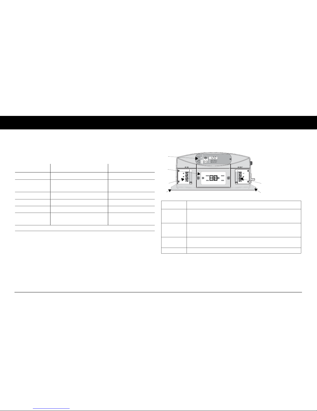
Front Panel (Standard Models)
2
1
3a 3b
Freedom HFS 1055 120VAC
4 4
Feature Description
1 Display panel displays inverter status and battery status information on the
screen. The panel can be detached to extend and mount the panel on a wall or
other location.
2 GFCI receptacles duri
ng inverter mode provide 1000 watts (Freedom HFS
1055 models) or 2000 watts (Freedom HFS 2055 models) of power to operate
AC devices.
3
WA GO
a
a. WAGO manufactures connection devices such as terminal blocks and related accessories.
Freedom HFS models indicated above use WAGO terminal blocks as AC input and output
connections.
AC terminals (with terminal inspection covers) for c
onnecting
AC input (3a
) and AC output (3b) wiring.
4 Mounting flange allo
ws you to mount the inverter permanently.
 Loading...