

Page 1
INSTALLATION INSTRUCTIONS
WPK1, 4, 6 and 8
THE WATERPAD™
WATERPROOF PROGRAMMABLE KEYPAD SYSTEM
OFF
DISC
+
DISC
---
TNR
TNR
VOL
VOL
CD
TUNER
TAPE
VCR1
SAT
CATV
DVD
VCR2
INTRODUCTION
THE WATERPAD™, an adaptation of the original Smart Pad
™ keypad system, is the world's first wall
2
mounted, fully programmable and configurable waterproof keypad. Now, outdoor, pool side, bathroom,
sauna and other high moisture installations can be handled with confidence. With the ease of the Dragon
Drop-IR™ software system, the Waterpad is fully programmable into four basic keypad configurations. In
addition, a large selection of button icon labels permits configurations to match the IR source and function
commands of virtually any A/V system.
Controllers
FEATURES
• Operates in high moisture environments in humidities up to 100% over a temperate range of 0° F (-18°C)
to 140° F (60° C).
• Unit is submersible in pure water in depths up to 6 inches or so. (The pressure of additional depths may
close the keys, preventing proper operation). See CAUTION note below.
• To maximize flexibility, the Waterpad is available in one, four, six and eight bank versions.
• A selection of 128 icon labels are included for affixing to source and function button locations.
• The membrane pad has 20 embossed buttons to which the icons are affixed, by the installer, with no
noticeable seam. Icons are peeled off a paper backing exposing an attaching adhesive.
• Icon color is black on white. Volume and Mute are also available in blue, if it is desired to highlight these
basic functions.
• The 4, 6 and 8 memory bank versions have LED indicators on each source button.
1
Page 2
• Two tiers of memory per button. Applies to both source select and control function buttons.
• Sequence commands, including 1 to 30 second delays, can be programmed under any button (including
the 2nd tier) without using up button spaces anywhere else on the keypad.
• Status input permits source buttons to light with +12V representing a system power ON condition as well
as the selected source.
• Intelligent Power Management. The first command in a sequence, normally a power command, will not
be sent if the status input is high (+12V). This prevents the sending of an unintended power command
when the system or zone is already on, thus preventing unintended shutdown when switching sources.
• All Waterpad programming is done using Xantech's exclusive Dragon Drop-IR™ software system
®
(available separately as Model DD4). It is a Windows
Xantech Smart Pad
derivative keypad systems. It allows the use of Xantech and/or installer prepared
2 or 3
based program that permits rapid configuring of
command libraries. It also permits the installer to keep computer files of all the client's keypad
configurations.
NOTE: IR commands
cannot
• Memorized contents are stored in an advanced E
be "learned" directly from hand held remotes into the Waterpad.
2
PROM within the Waterpad learning module. No
backup batteries are used or needed!
• Memory size is 64k Bits (8k Bytes)
• Xantech IR Receivers and other keypads can be used on the same IR bus with the Waterpad.
• The Waterpad mounts into standard 2-gang wall "J" boxes, for either new or retrofit applications.
CAUTION: While the WATERPAD™ is submersible, it was primarily designed to withstand high humidity
or wet areas where water may be splashed on it frequently. If you have an application where you wish
to place it under water, be sure the water is free of any corrosive agents such as chlorine. Also, do not
submerse it deeper than 6 inches.
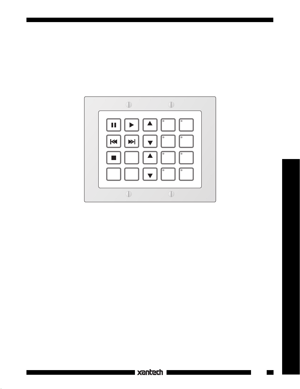
WATERPAD™ VERSIONS
To maximize the number of possible system applications, the Waterpad is supplied in four basic versions.
Each are defined and illustrated below with typical button icons applied. You may choose the icons and
place them in any arrangement you wish, to best fit taste and application. The only exception to this are
the source buttons. These are always in the right two columns and are identified by the small LED (source)
indicators in the upper left corner of each button. Each version includes an internal learning module, an 8terminal block, hardware, and an assortment of 128 button icons.
1 2 3
4 5 6
7 8 9
DISC
0
VOL
VOL
ONOFF
WPK-1
This version has 20 function buttons (no source
buttons). Use this when you have only one source
to control, such as a high capacity CD changer.
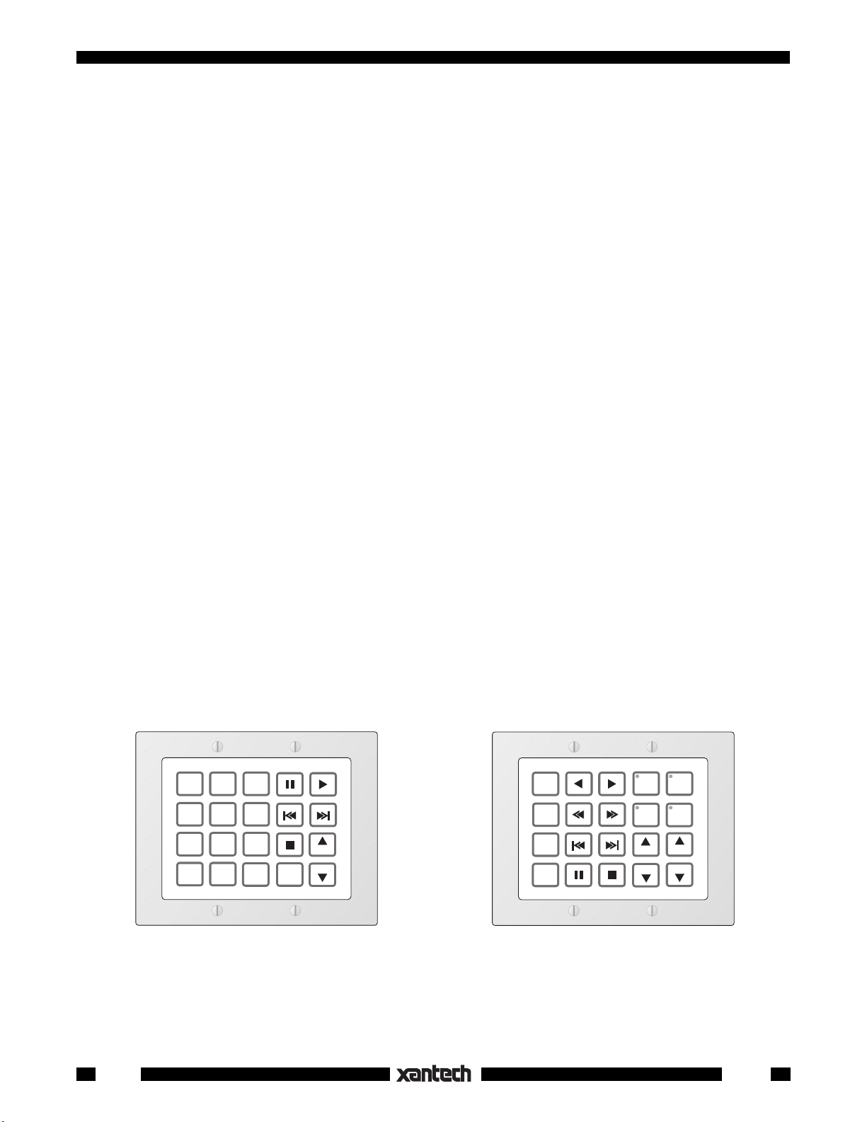
This version has 16 function buttons and 4 source
buttons. Use this when you wish to control two,
three or four source components.
DISC
+
DISC
---
MUTE
OFF
WPK-4
DVD
TNR
TNR
CD
TUNER
SAT
VOL
VOL
2
WPK1
Page 3
GUIDE MENU
CD
TUNER
CATVSAT
CD
CH
CH
TUNER
CATV
SAT
DISC
CH
This version has 14 function buttons and 6 source
buttons. Use this when you wish to control five or
six source components.
MUTE
OFF
CH
WPK-6
TAPE
VOL
DVD
VOL
DISC
MUTE
OFF
LD
TAPE
DVD
VCR
VOL
VOL
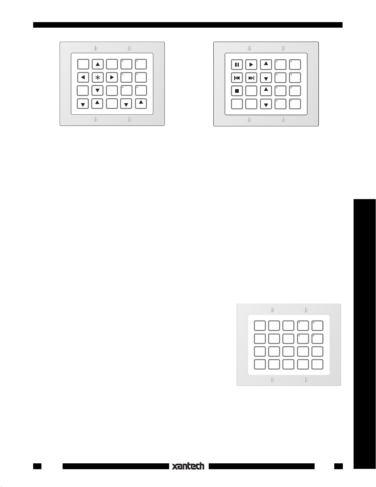
WPK-8
This version has 12 function buttons and 8 source
buttons. Use this when you wish to control seven
or eight source components.
INSTALLATION
When installing the Waterpad, we suggest that you proceed with the following order of events:
1. Determine the client's system components and needs in detail.
2. Determine the number of source components and function commands needed.
3. Pick the Waterpad version that best suits these needs, e.g. WPK-1, WPK-4, WPK-6 or WPK-8.
4. Using Dragon Drop IR™, place the button Icons in the desired locations on the virtual Waterpad and
program all buttons.
5. Transfer the program to the actual Waterpad and test all button commands for proper operation
before
affixing the real button Icons.
6. Affix the icons to all buttons.
7. Attach the inter-room cable to the terminal strip and test all button commands again for proper
operation.
8. Mount the keypad to the wall surface.
A Typical 4-Source Configuration
The following example will serve to illustrate this process. Suppose
a client wants to control an AM/FM stereo system with a Waterpad,
as in Fig. 3, from an outdoor location and that he has the following
equipment and system requirements:
1. An AM/FM receiver and 4 sources: TUNER (AM/FM), two CD
changers and a cassette TAPE deck.
2. When a source button is pressed, it turns on the AM/FM
receiver and the associated source.
3. The Waterpad must have the following function commands
for each source:
Fig. 1 4-Source Waterpad - Model WPK-4
TUNER: Tuner Up/Down (scroll of preset stations), AM/FM
(select).
CD 1 and CD 2: Play, Track Forward/Reverse, Pause, Stop, Disk+, Disk– (select).
TAPE: Play Forward, Play Reverse, Fast Forward/Rewind, Pause, Stop.
This is the basic client specification for this application of the Waterpad™.
Controllers
WPK1
3
Page 4

The next step is to determine which Waterpad version and
keypad button icons are required to perform this job, as follows:
CD 1
CD 2
MUTE
TUNER
TAPE
VOL
1. Since there are 4 sources, 4 banks will be required. We will
need the WPK-4 Waterpad version as shown in Fig. 1.
PLEASE NOTE:
All four versions of the Waterpad appear the
same before the button Icons are applied. That is, all the
TNR
TNR
AM
FM
buttons in the right 2 columns have a small dark circle in their
upper left corner where LEDs are located for bank (source)
DISC
DISC
---
A/B
+
OFF
VOL
indicators. These LEDs are programmed at the factory to
operate depending on the Waterpad version you ordered.
That is, on the WPK-1 none operate, on the WPK-4, the upper
4 operate, on the WPK-6 the upper 6 operate and on the
Fig. 2 Typical 4-Source Button Assignment
WPK-8, all 8 operate. On the versions where the LEDs do not
operate, the buttons work as normal function keys. When you apply function icons to them, the
unused LEDs are covered up as in Fig. 2.
2. The next step is to determine exactly what button icons are required to identify the source and control
functions needed.
3. We begin this process by assigning the source buttons first; CD1, TUNER, CD2 and TAPE. See Fig.
2. We do this by using Dragon Drop IR™. You may also pencil out your button designations on the
blank Waterpad illustrations at the end of this manual prior to using Dragon Drop if you wish.
4. Next, we assign the function control buttons based on the list of functions given in the client
specification, in the same manner.
5. Now that all the buttons have been assigned (as shown in Fig. 2), it is necessary to memorize the IR
commands and do the programming. Refer to the Dragon Drop IR™ Installation and Programming
Instructions for this process.
NOTE: In this example, the button assignments are placed in what is considered an ergonomically
pleasing arrangement. You may, however, assign the buttons in any arrangement you wish, to best
fit taste and application. The only exception to this is the 4 source buttons. These are permanently
assigned to the upper positions in the two right columns.
TM
PROGRAMMING THE WATERPAD
entirely using the Dragon Drop IRTM system with software DD3 ver. 3.0 and higher.
programmed directly!
Refer to the Dragon Drop IRTM DD4 Installation and Programming
- The Waterpad series was designed to be programmed
It cannot be
Instructions for details.
789-44
EMITTERS
MAIN ROOM
AM/FM Receiver
283M
Mouse Emitter
CD Changer 1
283M
Blink-IR™
CD Changer 2
283M
Cassette DecK
283M
Blink-IR™
Blink-IR™
Blink-IR™
Switched AC Outlet
on AM/FM Receiver
Power Supply
AC
Power
Strip
Plug into
Up to this point, the Waterpad exists only as a virtual
keypad in Dragon Drop-IR™.
For the final steps, we would
proceed as follows:
6. All commands are
tested, while still in
Dragon Drop-IR™, to
see that they actually operate all system functions.
7. The programmed data
is then transferred to the
THE WATERPAD™
(side view)
Cable Bushing
REMOTE LOCATION
(place in a dry location)
Six foot, 7-Conductor Cable
(End of cable is not
waterproof-see text).
Waterproof
8-Terminal Block
STATUS
(green)
COMMON
(orange)
+12V
(red)
GND
(black)
IR OUT
(white)
RX
(blue)
TX
(brown)
COM PORT Adapter PCB
(included in Dragon Drop IR
for program transfers)
4-Conductor
Inter-room Cable
(Unshielded OK)
TX RX COM
781RG
Power Supply
To 120 V AC
(unswitched)
789-44
Connecting Block
12VDC
+12 VDC
GND
STATUS
IR IN
+
RCVR
–
IR
White Striped Side ("+")
(Power ON/OFF Status
Voltage)
Power Cord for
AM/FM Receiver.
Plug into an
Unswitched
AC Outlet
CONNECTING BLOCK
®
"real" Waterpad, using
Dragon Drop-IR™.
786-00
(12V)
Fig. 3 Typical 4-Source Waterpad Controlled System
4
WPK1
Page 5

8. The Waterpad is now wired into the final system (refer to Figs. 3 & 5) and all commands tested again
--
before
applying the button icons.
9. If the system functions correctly, the button icons can then be applied, as shown in Fig. 4. Finally, the
Waterpad is mounted to the wall as shown in Fig. 6, 7, 8 & 9.
NOTE: The needed button icons are included with the Waterpad.
Applying Icons To The Waterpad Buttons
Each version of the Waterpad is supplied with 128 button icons on two mylar sheets. An assortment of both
source and function icons are provided and were chosen to cover practically any conceivable installation.
You will note that an extra set of Volume and Mute icons are provided in blue. Also, an extra set of function
symbol icons (play, stop, pause, etc.) are provided in grey. Use these icons to enhance visibility under low
light conditions or for color coding of functions or taste considerations. For indoor applications, you would
normally use the more sedate white icons.
CAUTION: Before applying the icons, be sure to do the following first:
a) Complete all configuring and programming using the Dragon Drop IR software system.
b) Transfer the programmed data to the "real" Waterpad.
c) Print out a copy of the virtual programmed Waterpad from Dragon Drop and keep it nearby for
reference.
d) Test each button on the "real" Waterpad (without the icons attached) and be sure it executes all
desired commands.
e) Be sure the membrane surfaces of the Waterpad, your hands and the icon sheets, are completely
dry and free of any grease or dirt.
Controllers
1. Carefully peel off a desired icon from the sheets. Try not to touch too much of the adhesive surface.
2. Align it very carefully within the rectangular embossed button area on the membrane of the Waterpad
and press it into place. See Fig. 4.
Be sure you have the correct button location. Use the printed virtual Waterpad as your guide.
CAUTION: You must be very certain that you have the correct location and that the icon is aligned
correctly. The adhesive
is a waterproof type and
is very aggressive. If you
have to pull it up to reposition it, it may not bond
ICONS on Paper
Backed Sheet
(2 sheets included)
AM
FM
ICON (has adhesive backing)
ICON fits within
embossed button
area on membrane
well enough to hold properly the second time. You
AUX
SAT
AM
INPUT
SHFL
SHUT
SPKR
TIME
TRACK
TV
UP
VIDEO
5
6
7
8
9
0
VCR
SCRN
SCRN
TNR
TNR
VOL
VOL
VOL
VOL
MUTE
TV
TV
Membrane
WATERPAD™
(without decorator style cover plate)
would have to purchase
a spare set of icons in
order to replace the damaged one(s).
3. Affix the remainder of the
icons in the same manner.
CAUTION:
If you damage the membrane (e.g.
by trying to dig out an
AUX l
SAT 1
CAM
SAT 2
CATV
TAPE
Custom labels for WPK
#1
CD
TAPE 1
CD 1
TAPE 2
CD 2
TUNER
DAT
TV
AMP
ANT
CLEAR
DISC
DISC
DISC
LINE
MENU
MUTE
MUTE
ON
MUTE
OFF
OFF
+
ON
---
icon with a knife, etc.)
so that it loses its watertight seal, it will void
Fig. 4 Icon Application
the warranty!
WPK1
5
Page 6

Fig. 5 illustrates the terminal block,
COM PORT adapter & the lead termination legend for the Waterpad.
The 8-terminal block is included with
each Waterpad. The COM PORT
adapter is included with each DD4
Dragon Drop-IR software package.
• Four of the seven leads are for the
standard Xantech IR bus, consisting of +12V, IR OUT (IR -signal),
STATUS and GND.
• The remaining three leads are for
THE WATERPAD™
(side view)
Six foot 7-Conductor Cable
(End of cable is not
waterproof-see text).
8-Terminal Block
Spare terminal
(for future use)
+12V
(red)
GND
(black)
STATUS
(green)
IR OUT
(white)
COMMON
(orange)
RX
(blue)
TX
(brown)
STATUS JUMPER
(use
only
if STATUS is
not
used. See "Power
Management" below).
4-Conductor
Inter-room cable
(to controlled
equipment).
TX RX COM
the COM PORT. The COM PORT
Adapter PCB allows direct plug-in
connection of the interface cable
Waterproof
Cable Bushing
COM PORT Adapter PCB
(included in Dragon Drop IR
for program transfers)
that connects the PCIR-1 to the
Waterpad for program transfers
Fig. 5 Cable Terminations
from Dragon Drop IR™. Refer to
the Waterpad portion of the Dragon Drop IR™ instructions for details.
CAUTION: The end of the cable, where the leads emerge from the sheath, is not water tight. To prevent
seepage of water up the interior of the cable to the inside of the Waterpad,
placed under water or in a wet location
. The 6-foot cable allows sufficient length to pull the cable end
do not allow the end to be
to a compartment or room area where it can be connected to the 8-terminal block in a dry environment.
Power Management
Like the Smart Pad
, the Waterpad™ has the ability, via the STATUS terminal, to prevent unintended
2 or 3
power turnoffs when power commands are sequenced with source commands.
• The Waterpad stops the first command in a sequence (the power command) when the STATUS terminal
is high (+12V DC = ON).
• Conversely, when the system is OFF, the first command (power) will be sent since the STATUS terminal
is low (0V).
• This assumes that +12V and 0V, representing a system ON and OFF condition, is applied to the STATUS
terminal (see Fig. 5)
• See Fig. 3 for STATUS connections in a typical system.
NOTE: If power management is not used (i.e. 3-wire hookups), a short jumper must be connected between
the STATUS and +12V terminals (see Fig. 5).
This powers the source button LEDs so they will come on with the selected bank. In this case, you must
put the system power command under an ON/OFF button (not under the source buttons). Also, source
commands must be placed twice under each source button in a 2-command sequence.
need to make two initial button presses to start the system, one for ON and one to select the source
The user will then
.
Also, when programming the Waterpoad for control of the ZPR68, you will need to place the source
select commands twice under each source button so that the sources can be selected after zone
turn-on.
MOUNTING
The Waterpad is designed to mount into most standard 2-gang "J" boxes in basically the same way as other
wall mounted decorator style components. The "J" boxes may be either of the new construction or retrofit
varieties. Consider the following when planning the mounting of the Waterpad:
• The Waterpad requires considerable room in the J-box.
6
WPK1
Page 7

• For retrofit (existing construction) applications, use high volume boxes, such
as the 2-gang Slater Retrofit 32 cu. inch
#6-32 x 1/2 Slot White
1
Oval Hd Screw (4)
#6-32 x 3/4 PH Flat Hd
3
Screw (4)
"J"-Box
(Retro-Fit type)
4
box.
Adapter Plate
• Most high volume new construction Jboxes will work. A "P" ring could also be
used.
• NOTE: Be sure to check fit
before
9
Decorator Style
Cover Plate
2
Water tight
WATERPAD™
Unit
(side view)
5
CAUTION:
6
Pressure Relief Hole. See step 7 below.
#4-40 x 1/4 PH Pan Hd Screw (1)
7
and O-ring (1). Install into Relief Hole
at installation site only. See text.
buying large quantities of J-boxes for
the job.
• Since the Waterpad is fully enclosed, it
may be possible, with some types of
sturdy wall materials, to mount it directly to the wall surface. See Fig. 9.
Mounting Procedure - Retrofit J-Box
#6-32 x 5/16 PH Flat Hd
8
Screw (4)
Wall Material
Fig. 6 Mounting the Waterpad into a Retrofit type J-box.
1/8" diameter x 1/4" deep
clearance holes (4) for
Cover Plate mounting
screws (see step 2 below).
To mount the Waterpad using a retrofit J-box, refer to Fig. 6 and proceed as follows:
1. Temporarily mount or hold the J-box to the wall opening.
2. Using the Adapter Plate
(supplied) as a template,
mark, then drill four 1/8" x 1/4"
holes in the wall material to
allow clearance for the ends
of the #6-32 x 1/2" cover plate
screws . This allows the
cover plate to be pulled down
flush to the wall in step 9. See
Figs. 6 & 8.
#6-32 x 1/2 Slot White
1
Oval Hd Screw (4)
9
Decorator Style
Cover Plate
2
Water tight
WATERPAD™
Unit
(side view)
4
"J"-Box
(Retro-Fit type)
8-Terminal Block
+12V
(red)
GND
(black)
STATUS
(green)
IR OUT
(white)
COMMON
(orange)
RX
(blue)
TX
(brown)
4-Conductor
Inter-room cable
(to controlled
equipment).
3. Thread the 6-foot cable from
the Waterpad through the
Adapter Plate and through
a knockout hole in the back of
the J-box .
4. Run the 6-foot cable from the
back of the J-box to a dry
Wall Material
Fig. 7 Installed Waterpad - Using a Retrofit type J-box.
Cable End and Terminal Block
(located in a dry area or compartment)
6-foot, 7-Conductor Cable
location in an adjacent compartment or room and make connections to the 8-terminal block and the 4-conductor inter-room cable.
Refer to Figs. 3 & 7.
5. Attach the J-box to the wall.
6. Attach the Adapter Plate to the J-box using the four #6-32 x 3/4" Flat Hd screws (supplied).
7. Install the #4-40 x 1/4" Pan Hd screw and O-ring (supplied) into the Pressure Relief Hole . Tighten
until you see some compression of the O-ring.
CAUTION: A Pressure Relief Hole is provided to prevent the buildup of internal pressure that could
damage the membrane during"storage and shipping conditions. When the Waterpad is installed at
the final site, however,
the screw and O-ring must be installed prior to exposure to moisture!
Failure to do so will void the warranty!
8. Using the four #6-32 x 5/16" PH Flat Hd screws (supplied), attach the Waterpad to the Adapter
Plate . See Figs. 6 & 7.
Controllers
WPK1
7
Page 8

9. The final step is to attach the Decorator Cover Plate (supplied) to the front of the Waterpad assembly
using the four #6-32 x 1/2" Slot White
Oval Hd screws (supplied).
Mounting into a New Construction
#6-32 x 1/2 Slot White
1
Oval Hd Screw (4)
#6-32 x 3/4 PH Flat Hd
3
Screw (4)
"J"-Box
(New Construction
4
Type)
J-Box
The procedure to mount the Waterpad
into a new construction type J-box is
essentially the same as that for a retrofit
J-box.
1. The main difference is that you will
need to have access to the rear of
9
Decorator Style
Cover Plate
2
Water tight
WATERPAD™
Unit
(side view)
Adapter Plate
5
CAUTION:
6
Pressure Relief Hole. See step 7, page 8.
#4-40 x 1/4 PH Pan Hd Screw (1)
7
and O-ring (1). Install into Relief Hole
at installation site only. See text.
the new construction J-box so that
the 6-foot, 7-conductor cable can be
pulled through the knockout hole
and run to a dry location in an adjacent compartment or room.
2. You would then make connections
#6-32 x 5/16 PH Flat Hd
8
Screw (4)
Wall Material
Fig. 8 Mounting the Waterpad into a New Construction type J-box.
1/8" x 1/4" clearance holes (4)
for Cover Plate mounting
screws (see text).
to the 8-terminal block and the 4conductor inter-room cable and carry out all the remaining steps as described for retrofit J-box
mounting. Refer to steps 1 through 9 previous and Fig. 8.
Mounting Directly to a Wall Surface
If the wall material is sufficiently strong so that it will hold the threads of sheet metal or wood screws, you
may be able to mount the Waterpad directly to the wall surface. Refer to Fig. 9 and proceed as follows:
1. Use the Adapter Plate as a template to mark a cutout opening for the Waterpad on the wall and to
locate pilot holes for the four Adapter Plate mounting screws . Also, mark spots for clearance holes
for the ends of the #6-32 x 1/2" cover plate screws .
2. Cut the opening for the Waterpad.
3. Using a #32 bit, drill four counter-
sunk pilot holes 3/4" deep for the
Oval Hd Screw (4)
#6 x 3/4" PH Flat Hd
3
Sm Screw (4)
0.116" (#32 drill bit) x 3/4"
countersunk pilot holes (4)
for Adapter Plate & mounting
screws. (See step 3 above).
#6-32 x 1/2 Slot White
1
Adapter Plate and the mounting
screws .
Adapter Plate
4. Drill four 1/8" x 1/4" holes in the wall
material to allow clearance for the
ends of the #6-32 x 1/2" Cover Plate
screws .
9
Decorator Style
Cover Plate
2
Water tight
WATERPAD™
Unit
(side view)
5
CAUTION:
6
Pressure Relief Hole. See step 7, page 8.
#4-40 x 1/4 PH Pan Hd Screw (1)
7
and O-ring (1). Install into Relief Hole
at installation site only. See text.
5. Using the four #6 x 3/4" Flat Hd
Sheet Metal screws (supplied),
attach the Adapter Plate to the
wall.
6. Run the 6-foot 7-conductor cable
#6-32 x 5/16 PH Flat Hd
8
Screw (4)
Wall Material
1/8" x 1/4" clearance holes (4)
for Cover Plate mounting
screws (see text).
from the Waterpad through the wall
opening to a dry location in an adja-
Fig. 9 Mounting the Waterpad directly onto a wall without a J-box.
cent compartment or room. Make connections to the 8-terminal block and the 4-conductor inter-room
cable. Refer to Figs. 3 & 7.
7. Finish by following steps 7 through 9 under "Mounting Procedure - Retrofit J-Box".
8
WPK1
Page 9

TROUBLESHOOTING
If you encounter problems, review each of the following items and take corrective action as described. If
problems persist, contact Xantech Technical Support.
1. The Waterpad does not have RESTORE or CLEAR MEMORY buttons as does the
SmartPad
. How do I perform these functions on the Waterpad, if needed?
2 or 3
a) To perform the RESTORE function, simply remove the 12 VDC power from the unit for 10-15
seconds, then reapply. Programmed contents in the memory will not be disturbed.
b) To CLEAR MEMORY, remove power as above, but hold down any button on the keypad
continuously while reapplying power. Bear in mind that this process will erase all keypad
contents.
TM
2. The Waterpad has problems with the transfer of data from Dragon Drop IR
or execution of IR
commands after data transfer.
A corrupted or incorrectly learned IR code has been transferred to the Waterpad or a corrupted code
preexists in the Waterpad learning module.
a) Perform the RESTORE or CLEAR MEMORY function on the Waterpad, then repeat the transfer
TM
procedure from the Dragon Drop IR
.
b) If the problem persists, test all IR commands per item 1 in the TROUBLESHOOTING section of
TM
Dragon Drop IR
, replacing any defective commands. Then repeat step a) above.
For additional details on troubleshooting IR programming problems, refer to the TROUBLESHOOT-
TM
ING section of Dragon Drop IR
"Installation and Programming Instructions"
3. The screws that attach the decorator style cover plate over the Waterpad do not screw in fully,
preventing the cover plate from being tightened down.
The wall surface is interfering with the ends of the screws, preventing full tightening.
Clearance holes must be drilled in the wall surface to allow full travel of these screws. Follow the
procedure in step 2, under Mounting Procedure - Retrofit J-Box.
Controllers
SPECIFICATIONS
2
Memory: 8 kbytes E
PROM
IR Carrier Frequency: 31.25 kHz to 71.5 kHz
Power Requirements: 12V DC - 70 mA without Status - 85 mA with Status
(Requires Xantech 781RG or 782 Power Supplies)
Conductors: Normal 3-wire Xantech IR receiver system compatible (4th wire for status indication)
Connections: 6-foot, 7-conductor cable terminated in an 8-screw terminal block: 4-conductors for +12V,
STATUS, IR OUT& GND plus 3-conductors for COM PORT leads (RS232 signal compatible).
Cable Requirements: Four-conductor/24 gauge up to 150', 22 gauge up to 400', 20 gauge up to 1500' and
18 gauge up to 4000' (unshielded OK)
NOTE: The Waterpad will not operate in the 2-wire Phantom Power Mode.
STATUS Terminal Power Management Turn-on Voltage: 5 to 20 volts DC (5mA @ 12V DC)
Maximum current output: 100 mA
Depth behind mounting plate: 2-3/8"
Max. Submersible Depth in Pure Water: 6 inches
Max. Temperature Operating Range: 0° F (-18°C) to 140° F (60° C)
*Fits two-gang wall boxes for both new & existing construction •Decorator-style wall cover plate included
PATENT PENDING
®
Windows
WPK1
and Microsoft® are registered trademarks of Microsoft Corporation
9
Page 10

Use these blank Waterpad panels when planning button layouts.
1-29-01
Rev.D
10
WPK1
 Loading...