


INSTALLATION INSTRUCTIONS
PA640
SIX CHANNEL POWER AMPLIFIER
& Amplifiers
Preamplifiers
1

GENERAL INFORMATION
To enhance the ease of installation and obtain optimum performance from the PA640, we recommend that you first become familiar with all its features and special capabilities by studying the descriptions and
POWER |
REMOTE |
|
ON/OFF |
®
PA640
SIX CHANNEL POWER AMPLIFIER
SYLMAR, CA |
MADE IN U.S.A. |
LEVEL |
|
BRIDGED |
LEVEL |
|
BRIDGED |
LEVEL |
|
BRIDGED |
1V |
C H 1 |
C H 2 |
1V |
C H 3 |
C H 4 |
1V |
C H 5 |
C H 6 |
|
STEREO |
|
STEREO |
|
STEREO |
3V |
.2V |
3V |
.2V |
3V |
.2V |
LINE INPUTS |
|
|
|
LINE INPUTS |
|
|
|
LINE INPUTS |
INPUT PANEL
Fig. 1 The Model PA640
instructions in this manual.
The PA640 was designed to meet the audio power amplifier needs of custom installed multi-zoned systems with high sonic quality. It's 6-5-4-3 multichannel capability permits a wide variety of other uses as well, such as surround sound home theater applications. Specific features and technology are as follows:
•Cost/Size Efficiency. The PA640 features six 40-watt power amplifiers. This permits each PA640 to drive 3-zones in a multi-zone system -- each with a 40-watt stereo amplifier per zone. The low profile design, plus multiple amplifiers in a single package, delivers high quality at a reasonable price.
•Input Level Flexibility. The input levels are individually adjustable (per stereo pair) from a low of 0.2 volts up to 3.3 volts. This gives the installer the ability to adjust the overall gain of the system or zone. For instance, there may be a need to adjust the amplifier to deliver a controlled, maximum sound level into a zone when the volume control on the preamp is set to maximum. This would act as a volume limiter for any particular zone (i.e. to prevent the kids from over-driving wall speakers, etc.).
•6-5-4-3 Output Flexibility. Each pair of amplifiers can be bridged to allow several channel and power output capabilities. It can be configured into four power packages as follows:
-Six 40-watt amplifiers.
-One 140 and four 40-watt amplifiers.
-Two 140 and two 40-watt amplifiers.
-Three 140-watt amplifiers.
This gives the PA640 added use in many other applications, such as driving surround sound speaker systems.
•Low Impedance Capability. Each amplifier is 2-Ohm safe under music conditions in stereo mode and 4-Ohm safe when bridged. This means, for instance, that you can drive two pairs of 8-Ohm speakers in stereo mode in each zone with ease.
•Discrete Output Devices. All output and driver transistors are separate devices connected in a fullcomplimentary Darlington configuration. This provides highest reliability in concert with highly linear dynamic performance free of T.I.M. and slew induced distortions.
•Auto Protection Circuit. Protects the PA640 if a short or very low impedance is detected at the speaker terminals. Each amplifier pair is protected separately, with an LED indicator showing which pair is in protection. Normal operation is restored automatically within 3 to 4 seconds after the short is removed.
•Remote ON/OFF Jack. This jack allows the PA640 to be powered on and off by a positive DC voltage ranging between 4 and 30 volts (11 mA @ 12 V). Specifically, it permits the 12 volt CO (Control Output) from the Xantech ZPR68 to power one or more PA640's on and off automatically with zone ON/OFF commands.
|
|
|
|
|
|
|
|
2 |
|
|
|
|
|
|
|
|
|
PA640 |
||
|
|
|
|
|
|
|
|
|
|
|
|
|
|
PA640 PANEL DESCRIPTIONS
1 2
POWER |
REMOTE |
|
ON/OFF |
||
|
®
|
LEVEL |
|
BRIDGED |
LEVEL |
|
BRIDGED |
LEVEL |
|
BRIDGED |
PA640 |
1V |
C H 1 |
C H 2 |
1V |
C H 3 |
C H 4 |
1V |
C H 5 |
C H 6 |
SIX CHANNEL POWER AMPLIFIER |
|
|
|
|
|
|
|
|
|
|
STEREO |
|
STEREO |
|
STEREO |
3V |
.2V |
3V |
.2V |
3V |
.2V |
SYLMAR, CA |
MADE IN U.S.A. |
|
|
|
LINE INPUTS |
LINE INPUTS |
LINE INPUTS |
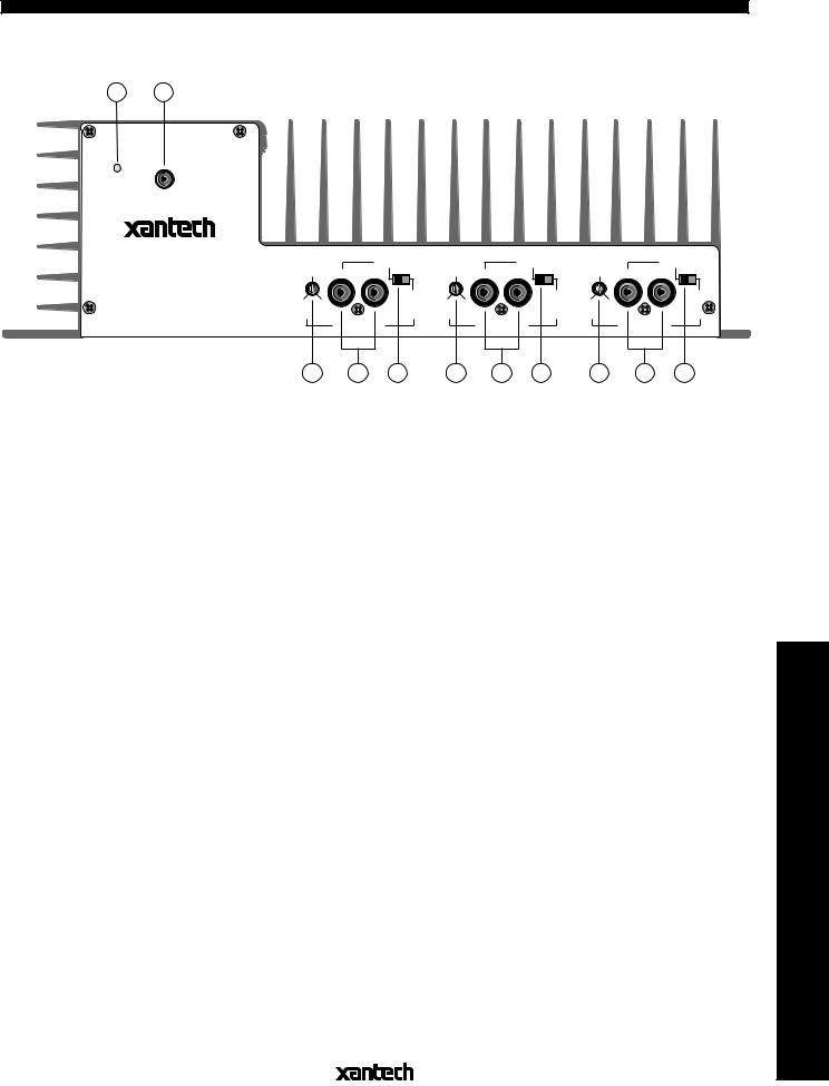
Fig. 2 PA640 Input Panel – |
3 |
4 |
5 |
3 |
4 |
5 |
3 |
4 |
5 |
|
|
Features and Functions |
|
||||||||||
|
|
|
|
|
|
|
|
|
|
||
1. POWER Indicator LED. This green LED lights when power is turned on by the POWER switch (item |
|
||||||||||
# 8) or by a DC voltage applied to the REMOTE ON/OFF jack (item #2). |
|
|
|
|
|||||||
2. REMOTE ON/OFF Jack. This 3.5mm mono mini jack allows the PA640 to be powered on and off by |
|
||||||||||
a positive DC voltage ranging between 4 and 30 volts (11 mA @ 12 V). For instance, it permits the |
|
||||||||||
12 Volt CO (Control Output) from a Xantech ZPR68 IR controlled preamp to power the PA640 ON and |
|
||||||||||
OFF automatically with zone ON/OFF commands. The DC Voltage must be applied continuously to |
|
||||||||||
hold the ON condition and go to less than 0.5 Volt for the OFF condition. |
|
|
|
|
|||||||
NOTE: The POWER switch (item #8) must be left in the MANUAL OFF (REMOTE ON/OFF) |
|
||||||||||
position to permit the REMOTE ON/OFF jack to operate. |
|
|
|
|
|
|
|||||
3. Input LEVEL Control. This screwdriver adjustable control (for each stereo or bridged pair) allows the |
|
||||||||||
input level for full rated power output to be adjusted over a range of 0.2 volts to 3.3 volts (24.3 dB). |
|
||||||||||
Amplifiers |
|||||||||||
Normally you would adjust the driving preamp to max. volume, then set this control to the maximum |
|||||||||||
|
|||||||||||
volume that the client desires for a given zone or room. This prevents the system from being driven |
|
||||||||||
to potentially destructive power levels. |
|
|
|
|
|
|
|
|
|
||
4. LINE INPUTS. These RCA type jacks are the audio inputs for the amplifier. Connect them to the |
|
||||||||||
OUTPUT jacks of the driving preamp with good quality RCA type patch cables. Note that the inputs |
|
||||||||||
are marked CH1, CH2, CH3, etc., signifying the individual channels. They correspond to the like |
& |
||||||||||
marked speaker terminals on the OUTPUT & AC panel (item # 7). When the switches (item #5) are |
|||||||||||
Preamplifiers |
|||||||||||
set to the BRIDGED mode, CH1, CH3 and CH5 become the active inputs and CH2, CH4 and CH6 |
|||||||||||
|
|||||||||||
are disabled. |
|
|
|
|
|
|
|
|
|
|
|
5. BRIDGED/STEREO Switches. These switches allow each of the three pair of amplifiers to be placed |
|
||||||||||
in either the BRIDGED 140 Watt (single channel) mode, or in the STEREO 40 Watts/channel (two |
|
||||||||||
channel) mode. |
|
|
|
|
|
|
|
|
|
|
|
CAUTION: Be sure to have the POWER turned OFF when changing the position of this switch and |
|
||||||||||
when making the corresponding speaker connection changes. |
|
|
|
|
|
|
|||||
|
|
|
|
|
|
|
|
|
|
|
3 |
|
|
|
PA640 |
|
|
|
|
|
|
|
|
|
|
|
|
|
|
|
|
|
|
|
PA640 PANEL DESCRIPTIONS
|
|
|
|
|
|
|
P OW E R |
|
|
|
|
|
|
|
|
|
M A N U A L O N |
|
|
|
|
|
|
|
|
M A N U A L O F F |
|
|
|
|
|
|
|
|
( R E M O T E O N / O F F ) |
CH6 |
CH5 |
CH4 |
CH3 |
CH2 |
CH1 |
|
1 2 0 VAC |
F U S E |
+ – |
– + |
+ – |
– + |
+ – |
– + |
|
||
PROTECTION |
|
PROTECTION |
|
PROTECTION |
|
SPEAKER IMPEDANCE |
6 0 H Z |
5 A |
|
|
|
|
|
|
|
|
|
|
|
|
|
|
|
STEREO MODE: 8 Ohms Min. |
|
|
|
|
|
|
|
|
BRIDGED MODE: 16 Ohms Min. |
|
|
+ B R I D G E D – |
+ B R I D G E D – |
+ B R I D G E D – |
|
|
|
|||
S P E A K E R S |
S P E A K E R S |
S P E A K E R S |
|
|
|
|||
6 7 6 7 6 7 8 9 10
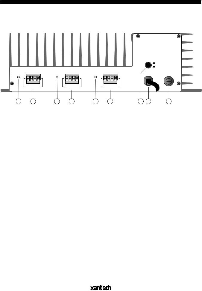
Fig. 3 PA640 Output & AC Panel – Features and Functions
6.PROTECTION Indicator LED's. These red LED's, one for each pair of channels, light for 3 to 4 seconds when the amplifier senses a short circuit or a very low load impedance (under 2-Ohms) at the speaker terminals. This protects the amplifier from potentially harmful conditions. If the short condition or the input signal is not removed, the amplifier will continue to cycle on and off at the 3 to 4 second interval.
CAUTION: Do not allow this to continue for a lengthy period of time. Reduce the volume, remove the short or low impedance condition and try again.
NOTE: The PROTECTION LED's will also light for 5 to 8 seconds when the amplifier is first turned on. This is a normal muting function that quiets the amplifier during start-up.
7.SPEAKER Terminals. These plug-in 4-terminal screw connectors permit speaker wire sizes up to 12 gauge. When making connections for the STEREO mode, be sure to observe the "+" and "–" polarity markings, just under the CH1, CH2, etc., markings, for each wire pair going to the speakers.
CAUTION: When making connections for the BRIDGED mode, remember only one speaker is being attached per amplifier pair. Be sure to observe the outer "+" and "–" polarity markings on the 4-terminal connector, as shown on the panel, for the one wire pair connecting to the speaker.
8.POWER Switch. When pressed to the IN position, power is applied to the PA640. This is the MANUAL ON position. When pressed again, it releases to the OUT position (MANUAL OFF), turning the unit OFF.
In addition, this switch must be left in the MANUAL OFF (REMOTE ON/OFF) position to permit external DC Voltage control of power ON/OFF for the PA640.
NOTE: The PA640 may also be powered ON/OFF with an external AC line switch (such as the switched AC outlet of a preamp, timer, etc.). For this type of operation, leave the POWER switch depressed to the MANUAL ON position.
9.AC LINE Cord. Depending on the application, plug into a switched or un-switched 120V 60 Hz AC outlet.
10.FUSE. When required, replace only with a fuse of the same type and rating (5 A 220V AC). Replacement with a fuse of higher rating will not protect the amplifier and will void the warranty.
|
|
|
|
|
|
|
|
4 |
|
|
|
|
|
|
|
|
|
PA640 |
||
|
|
|
|
|
|
|
|
|
|
|
|
|
|
 Loading...