

Page 1

INSTALLATION INSTRUCTIONS
WL85
Wall Link™
Plasma\LCD\LED\CFL Friendly
IR Receiver
WL85
IR RECEIVER
IR
Receiver
Status LED
Talkback LED
®
+12VD
C
STATUS
GND
IR OUT
DESCRIPTION
The WL85 is designed to reject interference from Plasma, LCD, LED
Displays and Compact Fluorescent Lamps (CFL) from entering the IR signal
line. This IR Receiver mounts easily into a single gang, electrical J-Box, is
supplied with mounting screws, and comes with a Decorator-style insert,
allowing the installer to use a Decorator-style wall cover plate. This provides
an integrated look for control of A/V equipment behind closed doors or any
IR Repeater System that is in close proximity to light sources described
above.
FEATURES
• J-Box Mounting with Decorator-style insert (available in white (included),
ivory, almond, & black)
• 4-screw terminal block for interface to Xantech Connecting Blocks
• Works in normal 3-wire mode
• Improved Compact Fluorescent Light rejection
• May be used in Direct Sunlight
• RF Grid included for EMI reduction
• Talk Back LED for IR reception and full system operation indication
• Status LED for system On/Off indication (requires 12VDC Source
@10mA)
• 7 units may be powered by one 781ERGPS power supply (regulated
12VDC 200mA supply)
Note: The WL85 will not operate in 2-wire Phantom Power mode
SPECIFICATIONS
• Infrared modulation frequency bandwidth: 30 - 60 kHz
• Reception range: up to 80 feet (18M), depending on remote control
output strength and ambient conditions.
• Reception angle: 55 degrees off axis at 50% range reduction
• Cable requirements: 3-conductor. Use 24-gauge up to 200' (61M), 22
gauges up to 600' (180M), 20-gauge up to 2000' (600M), 18-gauge up to
5000' (1.5KM) -- unshielded OK.
• Maximum transmission length: One mile using 18-gauge wire (1.6KM)
• Maximum current output: 100 mA (pulse)
• Dimensions: 1-3/4” W x 4-1/8” H x 1-1/8” D
• Power requirements: 12 volts DC @ 20mA
2
Page 2
45°
45°
PLASMA DISPLAY
780-95 Top View
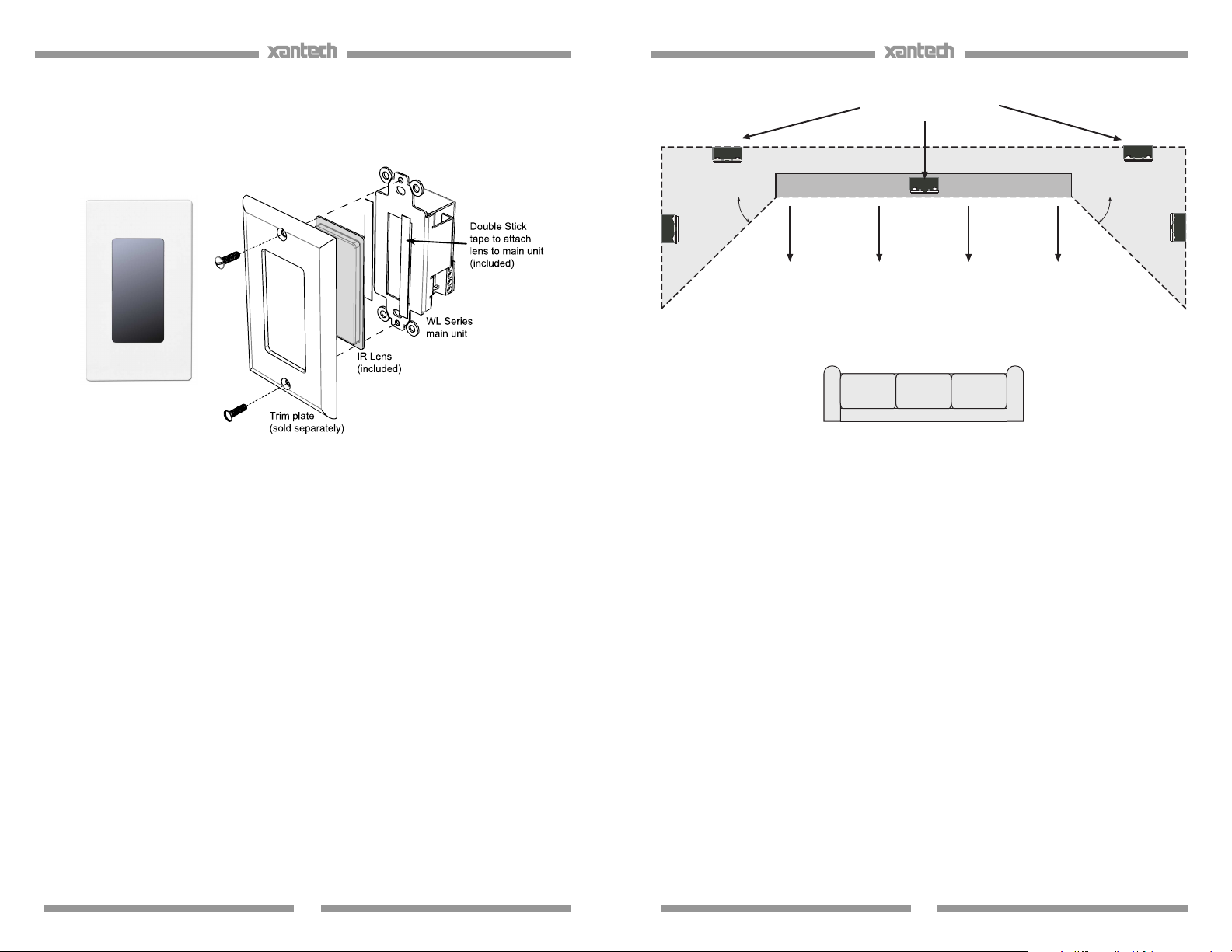
INSTALLATION
This unit is meant to be installed into a standard J-Box mounting box and
interfaced to Xantech Connecting Blocks, such as the CB12, 789-44, 79144, etc.
Figure 1 – WL series Assembly
CAUTION: THE J-BOX MUST NOT BE SHARED WITH 120/240VAC
CIRCUITS.
PLACEMENT
Placement of the IR Receiver does matter when used in the presence of a
Plasma Display. Ideally it should be placed somewhere around the Display
with the front of the receiver flush with the front of (or set back from) the
Display. If the WL85 needs to be placed in front of the display (such as on
an adjacent side wall perpendicular to the display), make sure it is placed at
a location at least 45 degrees off axis from the corners of the unit – see
Figure 2. The presence of Direct Sunlight and Fluorescent Lighting should
not affect the reception of this unit.
WL85 TOP VIEW
Figure 2 – WL series Placement
NOTE: Plasma interference can be reflected off of any item within approx. 3
feet from the front of the display. Keeping this in mind, make sure that the
WL85 is free of any obstruction that might reflect back into the receiving eye.
Note: While this unit shows strong rejection to standard 50/60Hz ‘ballasted’
fluorescent lighting, it is still prone to interference from CFL style Fluorescent
lighting.
MOUNTING
1. Pre-wire a 3-conductor cable (refer to Specifications section for
proper Wire Gauge) from the connecting block location to J-box
mounting location.
Note: If using the STATUS LED feature, use 4-conductor cable in
the appropriate gauge (see Figure 2)
2. Connect proper wires to the +12VDC, GND, STATUS (if applicable),
and IR OUT terminals on the rear of the WL85 as shown in Figure
2.
3. Secure the WL85 into the J-Box using the supplied screws.
3
4
Page 3

APPLICATION WIRING
A typical system, with a WL85, 781ERGPS Power Supply and 283M
Emitters plugged into a 789-44 Connecting Block, is shown in Figure 3:
1. Wire the appropriate leads of the 3 or 4-conductor cable from the
WL85 to the +12VDC, GND, STATUS (if applicable), and IR IN
terminals on the 789-44 Connecting Block
2. Plug in the 3.5mm mono mini plug from any of the 282, 284, 283
and 286 series Emitters into the jacks labeled EMITTERS on the
789-44 Connecting Block and affix the opposite end to the IR
Sensor Window of the controlled equipment.
3. Plug in the 2.1mm Coaxial power plug of the 781ERGPS Power
Supply (not included) into the jack labeled 12VDC on the 789-44
Connecting Block.
4. Plug the AC end of the 781ERGPS power Supply into an ‘unswitched’ 120VAC outlet.
WL Series
J-Box
IR Receiver
(rear view)
+12V
STATUS
GND
IR OUT
Add resistor in series
with STATS line to
adjust brightness, if desired.
(see text, next page)
REMOTE ROOM
WL
IR RECEIVER
XANTECH CORP.
+12VDC
STATUS
GND
IROUT
.
HandHeld
Remote
4- conductor
inter-room cable
(unshielded OK)
781ERGPS
To120VAC
(unswitched)
Connecting Block
12VDC
+12VDC
GND
STATUS
IR IN
+
–
RCVR
IR
White Striped Side ("+")
789-44
®
Satellite Receiver
E
mitter
Plug into
DVD
Switched AC Outlet
on A/V Receier
Emitter
Emitter
(see text)
786-00
Power supply
(12V at 10mA)
CONNECTING BLOCK
789-44
EMITTERS
A/V Receiver
MAIN ROOM
Figure 3 - Typical System Layout using WL series, 789-44, 781ERGPS,
and 283D Emitters
ADVANCED WIRING CONFIGURATION
WL85 may also be used in conjunction with other Xantech IR Receivers by
simply wiring in parallel on a Connecting Block such as the 791-44 Amplified
Block as shown in Figure 4 below.
1. Connect all IR Receivers in parallel at the terminals of the
connecting block as shown in Figure 4 below.
2. Plug in the 2.1mm Coaxial power plug of the 781ERGPS (or 782)
Power Supply (not included) into the jack labeled PWR on the 78944CB.
NOTE: Up to 7 IR Receivers may be connected in parallel with a
single 781ERGPS power supply. If more IR Receivers or any
Keypads are required, check total current requirements and increase
power supply current rating accordingly; i.e. 782-00 - 1.2A power
Supply)
3. Plug in the Emitters 3.5mm mono mini plug (282, 284, 283 or 286
series) into the Emitter Outputs on the 791-44.
REMOTE ROOM1
®
+12V
GND
IR
OUT
REMOTE ROOM3 REMOTE ROOM4
ML Series
Micro Link™
IR Receivers
3-Wire
Cable
+12V
GND
+12V
STATUS
GND
IR OUT
WL95
IR RECEIVER
Red
Stripe
OUT
IR
REMOTE ROOM2
WL SeriesWL Series
J-Box IR ReceiverJ-Box IR Receiver
®
+12V
GND
IR
OUT
DL Series
Dinky Link™
IR Receiver
3-Wire
Cable
+12V
GND
WL85
IR RECEIVER
+12V
STATUS
GND
IR OUT
Red
(orwhite)
Stripe
IR
OUT
ML Series
Micro Link™
IR Receivers
7 Foot 3-Conductor
Cable with Quick
Connect Stereo
Mini Plug
3-Conductor
Room-toRoom Cables
(Home Runs)
Amplified Connecting Block
OUT
IR
RCVR
IR
12 VDC
781RG
Power Supply
To 120V AC
(unswitched)
MAIN ROOM, EQUIPMENT AREA, ETC.
791-44
HIGH
+1 2 VD C
GN D
STA TUS
IR IN
®
EM IT TE RS
791-44
AMPLIFIED
CONNECTING BLOCK
Satellite Receiver
283D
VCR
283D
AV Receiver
283D
CD Changer
283M
Cassette DecK
283D
Blink-IR™
Mouse Emitter
Emitter
Emitter
Emitter
Emitter
Figure 4 - Advanced Wiring Configuration using WL series, ML and DL
series, 781ERGPS Power Supply and multiple 283D’s
CAUTION: With any of these systems, be sure the 781ERGPS (or 782-00)
Power Supply is plugged into an un-switched AC outlet. This maintains the
780 system in "stand-by" operation so that power-on commands can be sent
to the controlled equipment.
USING THE STATUS LED INDICATOR
The WL85 Plasma Friendly IR Receiver includes a Status LED located just
below the Talkback LED (See cover page). This permits the system to have
a visible power ON/OFF indicator in the remote room.
When used with any of Xantech’s Whole-house Audio Video Entertainment
systems such as the MRC-88, or the ZPR68-10 Pre-Amp as part of the
normal 4-wire hookup, connect the terminal marked STATUS on the WL85
Plasma Friendly IR Receiver to the appropriate Zones STATUS (or CO)
connection on the MRC or ZPR system controller. See Figure 5 below. This
will give visual ON/OFF status of the associated zone on the AV System
Controller.
5
6
Page 4
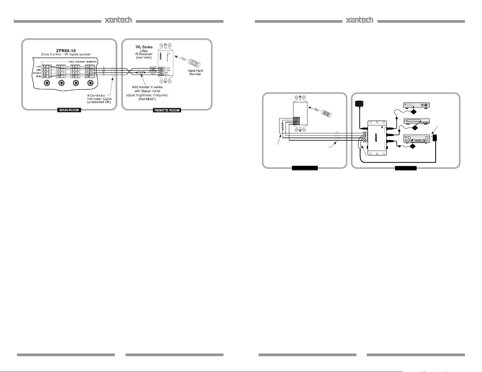
Figure 5 – Interfacing STATUS connection of WL85 with Zone STATUS
line on ZPR68-10
In Single Zone systems, the Status LED could show the ON/OFF status of
an AV Receiver. To achieve this, simply plug a 12vDC adapter, such as the
Xantech 781ERGPS Power Supply, into the switched AC Outlet of the AV
Receiver. The 12v ‘+’ and ‘-’ leads are then connected between the
STATUS (‘+’ lead) and GND (‘-’ lead) terminals of the WL85. The
Connecting Block makes a convenient tie-line for extending leads of the
Power Supply to the actual terminals of the WL85 as shown in Figure 6.
WL Series
J-Box
IR Receiver
(rear view)
+12V
STATUS
GND
IR OUT
Add resistor in series
with STATS line to
adjust brightness, if desired.
(see text, next page)
REMOTE ROOM
WL
IR RECEIVER
XANTECH CORP.
+12VDC
STATUS
GND
IROUT
.
HandHeld
Remote
4- conductor
inter-room cable
(unshielded OK)
781ERGPS
To120VAC
(unswitched)
ConnectingBlock
12VDC
+12VDC
GND
STATUS
IR IN
+
–
RCVR
IR
White Striped Side ("+")
789-44
®
Satellite Receiver
Emitter
Emitter
Emitter
Plug into
Switched AC Outlet
on A/V Receier
(see text)
786-00
Power supply
(12V at 10mA)
DVD
CONNECTING BLOCK
789-44
EMITTERS
A/V Receiver
MAIN ROOM
Figure 6 – Interfacing STATUS connection of WL85 to Switched Outlet
of AV Receiver
7
8
Page 5

TROUBLE SHOOTING:
1. Perhaps the most common problem you may encounter is stray IR
(infrared) or RF (radio frequency) interference preventing proper
operation of the controlled equipment.
• Fluorescent, Compact Fluorescent, Neon or Halogen lights,
Neon Art, and light dimmers.
• Direct of reflected sunlight.
• Infrared security sensors (active types).
• RF radiation from TV sets that may be close to the Micro
Link IR Receiver.
2. You can confirm the source of the interference by temporarily
turning off TV sets, isolating the Micro Link IR Receiver from all
sunlight and turning off all lights, light dimmers and Infrared security
systems. Then check to see if the Micro Link IR Receiver operates
the component.
• Sometimes interference will cause the red Talk-Back LED
on the front of the Micro Link IR Receiver to blink dimly,
intermittently, or continuously.
• The Talk-Back Led should only blink when you are sending
infrared commands to the Micro Link IR receiver from a
remote control.
• It may be necessary to move either the interfering source of
the Micro Link IR Receiver to achieve proper operation.
3. If the Talk-Back LED or the 286D Emitters do not blink when you are
sending IR commands to the Micro Link IR Receiver from a remote
control, check the following:
• Make sure the power supply is plugged securely into a live
AC electrical outlet.
• Be sure the stereo mini plug of the Micro Link IR Receiver is
plugged into the “IR RCVR” jack on the CB12 Connecting
Block, not into the “OUT” jack.
• Check to see that all the mini plugs are properly seated into
the mini jacks on the CB12 Connecting Block.
4. If the 283D Emitters blink, but the component does not respond,
reposition the 283D Emitter(s). They may not be located directly
over the component’s infrared receiving “window”. Consul the
owner’s manual of the unit or the manufacturer for the exact location
of the infrared “window”.
9
Limited Warranty
Xantech® warrants its products to be free of defects in materials or workmanship. This is a
Limited Lifetime warranty from the date of purchase by the original consumer. Any products
returned to Xantech and found to be defective by Xantech within the warranty period will be
repaired or replaced, at Xantech’s option, at no charge. Xantech will not be responsible for the
actual cost of installation or removal of the product, nor for any incidental or consequential
damages. Some states do not allow the exclusion or limitation of incidental or consequential
damages, so the above limitation may not apply to you. This warranty gives you specific legal
rights. You may have additional legal rights that vary from state to state.
Xantech Corporation
13100 Telfair Ave. 2F, Sylmar CA 91342 | Xantech.com
Installation Instructions, WL85 © 2009 Xantech Corporation
Document # 08905265B
This document is copyright protected. No part of this manual may be copied or reproduced in
any form without prior written consent from Xantech Corporation. Xantech Corporation shall not
be liable for operational, technical, or editorial errors/omissions made in this document.
10
 Loading...